Photoelectric Effect Photoelectric Effect (How Einstein really became famous!)
1
CSM_E3ZM_DS_E_5_2
Compact Photoelectric Sensor with Stainless Steel Housing
E3ZM
Features
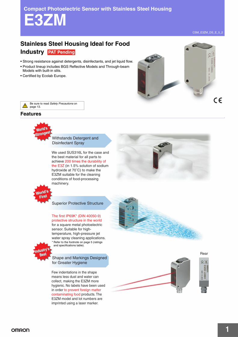
Withstands Detergent and Disinfectant Spray
Superior Protective Structure
Shape and Markings Designedfor Greater Hygiene
We used SUS316L for the case and the best material for all parts to achieve 200 times the durability of the E3Z (in 1.5% solution of sodium hydroxide at 70˚C) to make the E3ZM suitable for the cleaning conditions of food-processing machinery.
The first IP69K* (DIN 40050-9) protective structure in the worldfor a square metal photoelectric sensor. Suitable for high- temperature, high-pressure jet water spray cleaning applications.
World's
StrongestWorld's
Strongest
World's
FirstWorld's
First
Industry's
BestIndustry's
Best
Few indentations in the shape means less dust and water can collect, making the E3ZM more hygienic. No labels have been used in order to prevent foreign matter contaminating food products. The E3ZM model and lot numbers are imprinted using a laser marker.
Rear
* Refer to the footnote on page 5 (ratings and specifications table).
Stainless Steel Housing Ideal for Food Industry • Strong resistance against detergents, disinfectants, and jet liquid flow.
• Product lineup includes BGS Reflective Models and Through-beam Models with built-in slits.
• Certified by Ecolab Europe.
PAT Pending
Be sure to read Safety Precautions on page 13.

E3ZM
2
Structural Design That Provides Excellent Environment-resistance*
Unique Members of the E3ZM FamilyBGS Reflective Models
E3ZM-LS6@H/-LS8@HThree models with different fixed sensitivity (rated sensing distances) have been created. These models cover the sensing ranges of the E3Z-LS61.
Through-beam Inner Aperture Models
E3ZM-T63Fine beam without attaching an external aperture. This eliminates malfunctions from residual water drops, even immediately after washing.
A Better Fit for the ApplicationThe E3ZM can be used in those harsh cleaning environments in which the E3Z was difficult to use.E3ZM passed the material resistance tests and is certified by Ecolab.
Waterproofing ring: Fluorine rubber
Excellent resistance to detergents anddisinfectants.
Optical plate: Polymethylmethacrylate (PMMA)
Excellent resistance to detergentsand disinfectants. Hightransparency and other qualitiesgive PMMA excellent opticalcharacteristics.
Seal
The seal provides the durability to high-temperature and high-pressure water that complies with IP69K.
*Do not use the E3ZM in an oily environment.
Indicator cover: Polyethersulfone (PES)
Excellent resistance to detergents and disinfectants.
Excellent resistance to detergents and disinfectants. Also has excellent abrasion resistance.
Sensitivity adjustment and mode selector switch:Polyetheretherketone (PEEK)
Excellent corrosion resistance to many chemical reagents.
Case: SUS316L
Excellent resistance to detergents and disinfectants.
Cable: Polyvinylchloride
100mm
150mm
200mm
Same minimum detection object (0.7-mm dia.) as the E3Z-T61+E39-S65C (2-mm-dia. aperture).
0.8 m
This certificate is based on:
documented test procedures (test no.: F&E/P3-E Nr. 40-1) according to material resistance
defined product descriptions standardized cleaning procedure
Test procedure Ecolab-test F&E Nr. 40-1
Dipping test: • Complete immersion in solutions/liquid
Test period:• 14 days
Temperature: • room temperature (constant)
Analysis: Visual judgement like swelling, brittleness,
discoloring compared to zero-reference factor
(demineralized water) Photometric documentation
Product specifications:
P3-topax 56:Acid foam cleaning substance for food industry
P3-topax 66: Alkaline cleaning detergent with active chlorine for machine cleaning in food and beverage industry
P3-topax 91: Neutral disinfection agent based on quaternary ammonium compounds (QAV) for food industry
P3-topactive DES: Acid disinfectant based on Peracetic Acid and Hydrogen Peroxide for the food and beverage industry
Cleaning plan for food and beverage industry*
Rinsing with water 40 – 50°C Rinsing with low pressure. Rinsing from top to bottom in the
direction of the drains. Cleaning of the drains.
Foaming from bottom to topalkaline: P3-topax 66 2 – 5 % daily acid: P3-topax 56 2 % on demand temperature: cold up to 40°C contact time: 15 min. recommended
Rinsing with water 40 – 50°C Rinsing from top to bottom with low pressure
Spray disinfection P3-topax 91 1-2 %, 30 -60 minutes
Foam disinfection P3-topactive DES 1-2 %, 10-30 minutes *short description
Ecolab GmbH & Co. OHG P.O. Box 13 04 06
D-40551 Düsseldorf
certifies that for
OMRON Manufacturing of Germany GmbH Carl-Benz-Strasse 4
71154 Nufringen
material resistance tests
were performed with cleaning substances P3-topax 56, P3-topax 66, P3-topax 91, P3 Topactiv DES and demineralized water as a zero reference factor.
The material resistance of the tested series
Photoelectric Sensor E3ZM
to the P3 products used in the test can be considered to be positive according to the cleaning procedure mentioned overleaf.
Düsseldorf, 14th February 2006
Ecolab GmbH & Co. OHG
i.V. i. V.
Thomas Tyborski Reimund Laaff
Processing and wrapping ofmeat or raw food products

E3ZM
3
Ordering InformationSensors (Refer to Dimensions on page 15.)
*1. The Reflector is sold separately. Select the Reflector model most suited to the application.*2. Values in parentheses indicate the minimum required distance between the Sensor and Reflector.*3. Pre-wired Models with a 5-m cable are also available for these products. When ordering, specify the cable length by adding "5M" to the end of the model number
(e.g., E3ZM-LT61 5M).*4. Through-beam Models are also available with a light emission stop function. When ordering, add "-G0" to the end of the model number (e.g., E3ZM-T61-G0).*5. The model number of the Emitter is expressed by adding an "L" to the set model number in the table. Example: E3ZM-T61-L 2M
The model number of the receiver is expressed by adding a "D" to the set model number in the table. Example: E3ZM-T61-D 2MOrders for individual Emitters and Receivers are accepted. (Modifications are required for some models.)
Accessories (Order Separately)Reflectors (A Reflector is required for Retro-reflective Sensors: A Reflector is not provided with the Sensor. Be sure to order a Reflector.) (Refer to Dimensions on E39-L/F39-L/E39-S/E39-R.)
Note: When using a Reflector without a rated value, use 0.7 times typical value as a guideline for the sensing distance. * Values in parentheses indicate the minimum required distance between the Sensor and Reflector.
Sensing method
Appear-ance Connection method Sensing distance
ModelNPN output PNP output
Through-beam *4(Emitter + Receiver) *5
Pre-wired (2 m) *3 E3ZM-T61 2M E3ZM-T81 2M
Connector (M8, 4 pins) E3ZM-T66 E3ZM-T86
Pre-wired (2 m) *3 E3ZM-T63 2M E3ZM-T83 2M
Connector (M8, 4 pins) E3ZM-T68 E3ZM-T88
Retro-reflective with MSR function
Pre-wired (2 m) *3 E3ZM-R61 2M E3ZM-R81 2M
Connector (M8, 4 pins) E3ZM-R66 E3ZM-R86
Diffuse-reflective
Pre-wired (2 m) *3 E3ZM-D62 2M E3ZM-D82 2M
Connector (M8, 4 pins) E3ZM-D67 E3ZM-D87
BGS reflective(fixed distance)
Pre-wired (2 m) *3 E3ZM-LS61H 2M E3ZM-LS81H 2M
Connector (M8, 4 pins) E3ZM-LS66H E3ZM-LS86H
Pre-wired (2 m) *3 E3ZM-LS62H 2M E3ZM-LS82H 2M
Connector (M8, 4 pins) E3ZM-LS67H E3ZM-LS87H
Pre-wired (2 m) *3 E3ZM-LS64H 2M E3ZM-LS84H 2M
Connector (M8, 4 pins) E3ZM-LS69H E3ZM-LS89H
Name E3ZM-RSensing distance (typical) * Model Quantity Remarks
Reflector
3 m (100 mm) (rated value) E39-R1 1
• Reflectors are not provided with Retro-re-flective models.
• The MSR function is enabled.
4 m (100 mm) (rated value) E39-R1S 15 m (100 mm) E39-R2 1
2.5 m (100 mm) E39-R9 13.5 m (100 mm) E39-R10 1
Fog Preventive Coating 3 m (100 mm) E39-R1K 1Small Reflector 1.5 m (50 mm) E39-R3 1
Tape Reflector700 mm (150 mm) E39-RS1 11.1 m (150 mm) E39-RS2 11.4 m (150 mm) E39-RS3 1
Red light Infrared light
15 m
0.8 m(apertures built in)
*1
4 m (100 mm)
(Using E39-R1S)
*2
1 m
10 to 100 mm
10 to 150 mm
10 to 200 mm
E3ZM
4
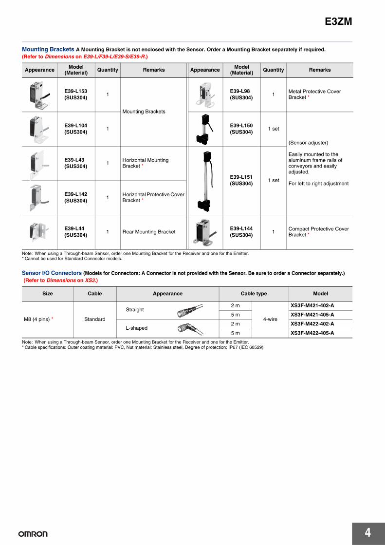
Mounting Brackets A Mounting Bracket is not enclosed with the Sensor. Order a Mounting Bracket separately if required. (Refer to Dimensions on E39-L/F39-L/E39-S/E39-R.)
Note: When using a Through-beam Sensor, order one Mounting Bracket for the Receiver and one for the Emitter.* Cannot be used for Standard Connector models.
Sensor I/O Connectors (Models for Connectors: A Connector is not provided with the Sensor. Be sure to order a Connector separately.) (Refer to Dimensions on XS3.)
Note: When using a Through-beam Sensor, order one Mounting Bracket for the Receiver and one for the Emitter.* Cable specifications: Outer coating material: PVC, Nut material: Stainless steel, Degree of protection: IP67 (IEC 60529)
Appearance Model(Material) Quantity Remarks Appearance Model
(Material) Quantity Remarks
E39-L153(SUS304)
1
Mounting Brackets
E39-L98(SUS304)
1 Metal Protective Cover Bracket *
E39-L104(SUS304)
1E39-L150(SUS304)
1 set
(Sensor adjuster)
Easily mounted to the aluminum frame rails of conveyors and easily adjusted.
For left to right adjustment
E39-L43(SUS304)
1 Horizontal Mounting Bracket *
E39-L151(SUS304)
1 set
E39-L142(SUS304)
1 Horizontal Protective Cover Bracket *
E39-L44(SUS304)
1 Rear Mounting BracketE39-L144(SUS304)
1 Compact Protective Cover Bracket *
Size Cable Appearance Cable type Model
M8 (4 pins) * Standard
2 m
4-wire
XS3F-M421-402-A
5 m XS3F-M421-405-A
2 m XS3F-M422-402-A
5 m XS3F-M422-405-A
Straight
L-shaped
E3ZM
5
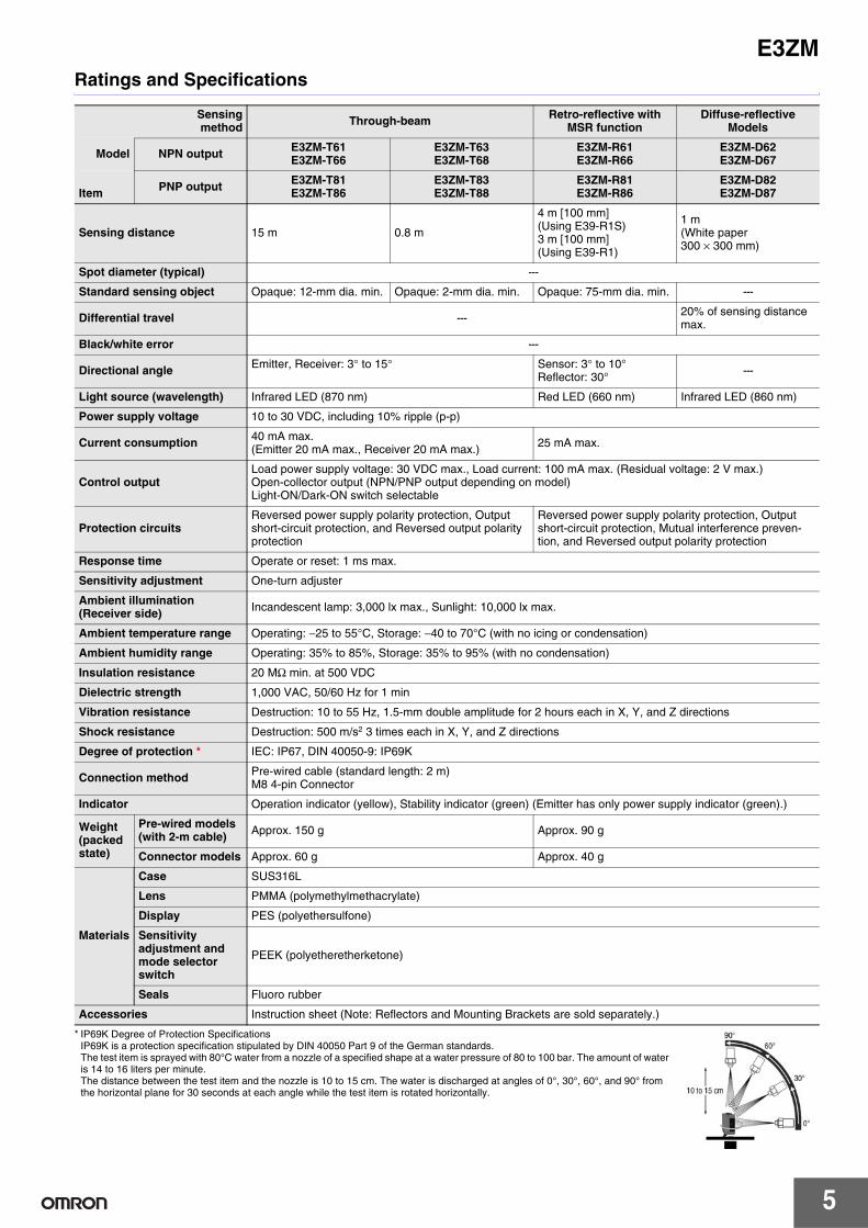
Ratings and Specifications
* IP69K Degree of Protection SpecificationsIP69K is a protection specification stipulated by DIN 40050 Part 9 of the German standards. The test item is sprayed with 80°C water from a nozzle of a specified shape at a water pressure of 80 to 100 bar. The amount of water is 14 to 16 liters per minute. The distance between the test item and the nozzle is 10 to 15 cm. The water is discharged at angles of 0°, 30°, 60°, and 90° from the horizontal plane for 30 seconds at each angle while the test item is rotated horizontally.
Sensingmethod Through-beam Retro-reflective with
MSR functionDiffuse-reflective
Models
Model NPN output E3ZM-T61E3ZM-T66
E3ZM-T63E3ZM-T68
E3ZM-R61E3ZM-R66
E3ZM-D62E3ZM-D67
Item PNP output E3ZM-T81E3ZM-T86
E3ZM-T83E3ZM-T88
E3ZM-R81E3ZM-R86
E3ZM-D82E3ZM-D87
Sensing distance 15 m 0.8 m
4 m [100 mm](Using E39-R1S)3 m [100 mm](Using E39-R1)
1 m(White paper 300 × 300 mm)
Spot diameter (typical) ---
Standard sensing object Opaque: 12-mm dia. min. Opaque: 2-mm dia. min. Opaque: 75-mm dia. min. ---
Differential travel --- 20% of sensing distance max.
Black/white error ---
Directional angle Emitter, Receiver: 3° to 15° Sensor: 3° to 10°Reflector: 30° ---
Light source (wavelength) Infrared LED (870 nm) Red LED (660 nm) Infrared LED (860 nm)
Power supply voltage 10 to 30 VDC, including 10% ripple (p-p)
Current consumption 40 mA max. (Emitter 20 mA max., Receiver 20 mA max.) 25 mA max.
Control outputLoad power supply voltage: 30 VDC max., Load current: 100 mA max. (Residual voltage: 2 V max.)Open-collector output (NPN/PNP output depending on model)Light-ON/Dark-ON switch selectable
Protection circuitsReversed power supply polarity protection, Output short-circuit protection, and Reversed output polarity protection
Reversed power supply polarity protection, Output short-circuit protection, Mutual interference preven-tion, and Reversed output polarity protection
Response time Operate or reset: 1 ms max.
Sensitivity adjustment One-turn adjuster
Ambient illumination (Receiver side) Incandescent lamp: 3,000 lx max., Sunlight: 10,000 lx max.
Ambient temperature range Operating: −25 to 55°C, Storage: −40 to 70°C (with no icing or condensation)
Ambient humidity range Operating: 35% to 85%, Storage: 35% to 95% (with no condensation)
Insulation resistance 20 MΩ min. at 500 VDC
Dielectric strength 1,000 VAC, 50/60 Hz for 1 min
Vibration resistance Destruction: 10 to 55 Hz, 1.5-mm double amplitude for 2 hours each in X, Y, and Z directions
Shock resistance Destruction: 500 m/s2 3 times each in X, Y, and Z directions
Degree of protection * IEC: IP67, DIN 40050-9: IP69K
Connection method Pre-wired cable (standard length: 2 m)M8 4-pin Connector
Indicator Operation indicator (yellow), Stability indicator (green) (Emitter has only power supply indicator (green).)
Weight (packed state)
Pre-wired models (with 2-m cable) Approx. 150 g Approx. 90 g
Connector models Approx. 60 g Approx. 40 g
Materials
Case SUS316L
Lens PMMA (polymethylmethacrylate)
Display PES (polyethersulfone)
Sensitivity adjustment and mode selector switch
PEEK (polyetheretherketone)
Seals Fluoro rubber
Accessories Instruction sheet (Note: Reflectors and Mounting Brackets are sold separately.)
E3ZM
6
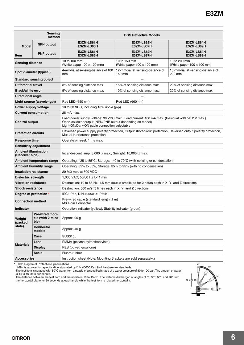
* IP69K Degree of Protection SpecificationsIP69K is a protection specification stipulated by DIN 40050 Part 9 of the German standards. The test item is sprayed with 80°C water from a nozzle of a specified shape at a water pressure of 80 to 100 bar. The amount of water is 14 to 16 liters per minute. The distance between the test item and the nozzle is 10 to 15 cm. The water is discharged at angles of 0°, 30°, 60°, and 90° from the horizontal plane for 30 seconds at each angle while the test item is rotated horizontally.
Sensingmethod BGS Reflective Models
Model NPN output E3ZM-LS61HE3ZM-LS66H
E3ZM-LS62HE3ZM-LS67H
E3ZM-LS64HE3ZM-LS69H
Item PNP output E3ZM-LS81HE3ZM-LS86H
E3ZM-LS82HE3ZM-LS87H
E3ZM-LS84HE3ZM-LS89H
Sensing distance 10 to 100 mm(White paper 100 × 100 mm)
10 to 150 mm(White paper 100 × 100 mm)
10 to 200 mm(White paper 100 × 100 mm)
Spot diameter (typical) 4-mm dia. at sensing distance of 100 mm
12-mm dia. at sensing distance of 150 mm
18-mm dia. at sensing distance of 200 mm
Standard sensing object ---
Differential travel 3% of sensing distance max. 15% of sensing distance max. 20% of sensing distance max.
Black/white error 5% of sensing distance max. 10% of sensing distance max. 20% of sensing distance max.
Directional angle ---
Light source (wavelength) Red LED (650 nm) Red LED (660 nm)
Power supply voltage 10 to 30 VDC, including 10% ripple (p-p)
Current consumption 25 mA max.
Control outputLoad power supply voltage: 30 VDC max., Load current: 100 mA max. (Residual voltage: 2 V max.)Open-collector output (NPN/PNP output depending on model)Light-ON/Dark-ON cable connection selectable
Protection circuits Reversed power supply polarity protection, Output short-circuit protection, Reversed output polarity protection, Mutual interference protection
Response time Operate or reset: 1 ms max.
Sensitivity adjustment ---
Ambient illumination (Receiver side) Incandescent lamp: 3,000 lx max., Sunlight: 10,000 lx max.
Ambient temperature range Operating: −25 to 55°C, Storage: −40 to 70°C (with no icing or condensation)
Ambient humidity range Operating: 35% to 85%, Storage: 35% to 95% (with no condensation)
Insulation resistance 20 MΩ min. at 500 VDC
Dielectric strength 1,000 VAC, 50/60 Hz for 1 min
Vibration resistance Destruction: 10 to 55 Hz, 1.5-mm double amplitude for 2 hours each in X, Y, and Z directions
Shock resistance Destruction: 500 m/s2 3 times each in X, Y, and Z directions
Degree of protection * IEC: IP67, DIN 40050-9: IP69K
Connection method Pre-wired cable (standard length: 2 m)M8 4-pin Connector
Indicator Operation indicator (yellow), Stability indicator (green)
Weight (packed state)
Pre-wired mod-els (with 2-m ca-ble)
Approx. 90 g
Connectormodels Approx. 40 g
Materials
Case SUS316L
Lens PMMA (polymethylmethacrylate)
Display PES (polyethersulfone)
Seals Fluoro rubber
Accessories Instruction sheet (Note: Mounting Brackets are sold separately.)

E3ZM
7
Engineering Data (Typical)Parallel Operating RangeThrough-beam Models Retro-reflective ModelsE3ZM-T@1(T@6) E3ZM-T@3(T@8) E3ZM-R@1(R@6)
Operating RangeDiffuse-reflective Models BGS Reflective ModelsE3ZM-D@2(D@7) E3ZM-LS@1H(LS@6H), Top to Bottom E3ZM-LS@1H(LS@6H), Left to Right
E3ZM-LS@2H(LS@7H), Top to Bottom E3ZM-LS@2H(LS@7H), Left to Right E3ZM-LS@4H(LS@9H), Top to Bottom
E3ZM-LS@4H(LS@9H), Left to Right
Dis
tanc
e Y
(m
m)
Distance X (m)
1500
−1500405 10 15 20 25 30 350
1000
500
0
−500
−1000
Y
X
0 500 1000 1500 2000
Dis
tanc
e Y
(m
m)
Distance X (mm)
-100
-80
-60
-40
-20
0
20
40
60
80
100
Y
X
150
−1501 2 3 4 5 60
100
50
0
−50
−100
E39-R1S
E39-R1
Y
X
Dis
tanc
e Y
(m
m)
Distance X (m)
120
100
80
60
40
20
0
−20
−40
−60
−80
−100
−120
140
−1401.80.2 0.4 0.6 0.8 1 1.2 1.4 1.60
Y
X
Sensing object: 300 × 300 white paper
Dis
tanc
e Y
(m
m)
Distance X (m)
4
2
0
−2
−4
−6
6
10020 40 60 800
Dis
tanc
e Y
(m
m)
Distance X (mm)
Y
X
Sensing object: 100 × 100 white paper
3
2
1
0
−1
−2
−3
4
−410020 40 60 800
Y
X
Dis
tanc
e Y
(m
m)
Sensing object: 100 × 100 white paper
Distance X (mm)
20
15
10
5
0
−5
−10
25
−15
−20
−25100 120 140 16020 40 60 800
Y
X
Sensing object: 100 × 100 white paper
Dis
tanc
e Y
(m
m)
Distance X (mm)
6
4
2
0
−2
−4
−6100 120 140 16020 40 60 800
Distance X (mm)
Sensing object: 100 × 100 white paper
Dis
tanc
e Y
(m
m)
Y
X
30
25
20
15
10
5
0
35
−5
−10
−15
−20
−25
−30
−35100 150 200 250500
Sensing object: 100 × 100 white paper
Dis
tanc
e Y
(m
m)
Distance X (mm)
Y
X
Sensing object: 100 × 100 white paper8
6
4
2
0
−2
−4
−6
−8100 150 200 250500
Distance X (mm)
Dis
tanc
e Y
(m
m)
Y
X

E3ZM
8
Excess Gain vs. DistanceThrough-beam Models Retro-reflective ModelsE3ZM-T@1(T@6) E3ZM-T@3(T@8) E3ZM-R@1(R@6)
Diffuse-reflective ModelsE3ZM-D@2(D@7)
Sensing Object Size vs. Distance Spot Diameter vs. DistanceDiffuse-reflective Models BGS Reflective ModelsE3ZM-D@2(D@7) E3ZM-LS@1H(LS@6H) E3ZM-LS@2H/LS@4H(LS@7H/LS@9H)
100
50
30
10
5
3
1
0.5
0.3
0.150454035302520151050
Distance (m)
Oper-ating level
Exc
ess
gain
rat
io (
mul
tiple
)
0.1
1
10
100
0 500 1000 1500 2000 2500Distance (mm)
Exc
ess
gain
rat
io (
mul
tiple
)
Oper-ating level
100
50
30
10
5
3
1
0.5
0.3
0.161 2 3 4 50
E39-R1S
E39-R1
Distance (m)
Oper-ating level
Exc
ess
gain
rat
io (
mul
tiple
)
100
50
30
10
5
3
1
0.5
0.3
0.12.50.5 1 1.5 20
Sensing object: 300 × 300 white paper
Distance (m)
Oper-ating level
Exc
ess
gain
rat
io (
mul
tiple
)
Sensing object: White paper
1.6
1.4
1.2
1.0
0.8
0.6
0.4
0.2
1.8
0.0600100 200 300 400 5000
Length d of sensing object (mm)
Dis
tanc
e (m
)
d
d
10
8
6
4
2
12
020 40 60 80 1000
Distance (mm)
Spo
t dia
met
er (
mm
)
18
16
14
12
10
8
6
4
2
20
050 100 150 200 2500
Distance (mm)
Spo
t dia
met
er (
mm
)

E3ZM
9
Sensing Distance vs. Sensing Object MaterialBGS Reflective ModelsE3ZM-LS@1H(LS@6H) E3ZM-LS@2H(LS@7H) E3ZM-LS@4H(LS@9H)
Inclination Characteristics (Vertical)BGS Reflective ModelsE3ZM-LS@1H(LS@6H) E3ZM-LS@2H(LS@7H) E3ZM-LS@4H(LS@9H)
Inclination Characteristics (Horizontal)BGS Reflective ModelsE3ZM-LS@1H(LS@6H) E3ZM-LS@2H(LS@7H) E3ZM-LS@4H(LS@9H)
120
100
80
60
40
20
0Whitepaper
Veneer Card-board
Blackpaper
Blackrubber
SUS Mirrorsurface
Material
Sen
sing
dis
tanc
e (m
m) 180
160
140
120
100
80
60
40
20
0Whitepaper
Veneer Card-board
Blackpaper
Blackrubber
SUS Mirrorsurface
Material
Sen
sing
dis
tanc
e (m
m) 250
200
150
100
50
0Whitepaper
Veneer Card-board
Blackpaper
Blackrubber
SUS Mirrorsurface
Material
Sen
sing
dis
tanc
e (m
m)
40
30
20
10
0
−10
−20
−30
−40
50
−50804020 600−40 −20−60−80
Inclination angle θ (°)
Sen
sing
dis
tanc
e va
riatio
n (%
)
Upwards and Downwards
Inclinationangle
+θ−θ
Centerline
Sensing object
40
30
20
10
0
−10
−20
−30
−40
50
−50804020 600−40 −20−60−80
Inclination angle θ (°)
+θ−θ
Sen
sing
dis
tanc
e va
riatio
n (%
)
(Upwards and Downwards)
Inclination angle
Sensingobject Center
line
40
30
20
10
0
−10
−20
−30
−40
50
−50804020 600−40 −20−60−80
40
30
20
10
0
−10
−20
−30
−40
50
−50804020 600−40 −20−60−80
Inclination angle θ (°)
+θ+θ
Sen
sing
dis
tanc
e va
riatio
n (%
)
Centerline
Sensingobject
(Upwards and Downwards)
Inclination angle
40
30
20
10
0
−10
−20
−30
−40
50
−50804020 600−40 −20−60−80
40
30
20
10
0
−10
−20
−30
−40
50
−50804020 600−40 −20−60−80
Inclination angle θ (°)
+θ−θSensing
object Centerline
(Left and Right)
Inclinationangle
Sen
sing
dis
tanc
e va
riatio
n (%
)
40
30
20
10
0
−10
−20
−30
−40
50
−50804020 600−40 −20−60−80
40
30
20
10
0
−10
−20
−30
−40
50
−50804020 600−40 −20−60−80
Sen
sing
dis
tanc
e va
riatio
n (%
)
Inclination angle θ (°)
+θ−θSensing
object Centerline
(Left and Right)
Inclinationangle
40
30
20
10
0
−10
−20
−30
−40
50
−50804020 600−40 −20−60−80
+θ−θ
Inclinationangle
(Left and Right)
Centerline
Sensingobject
Inclination angle θ (°)
40
30
20
10
0
−10
−20
−30
−40
50
−50
Sen
sing
dis
tanc
e va
riatio
n (%
)
804020 600−40 −20−60−80
E3ZM
10
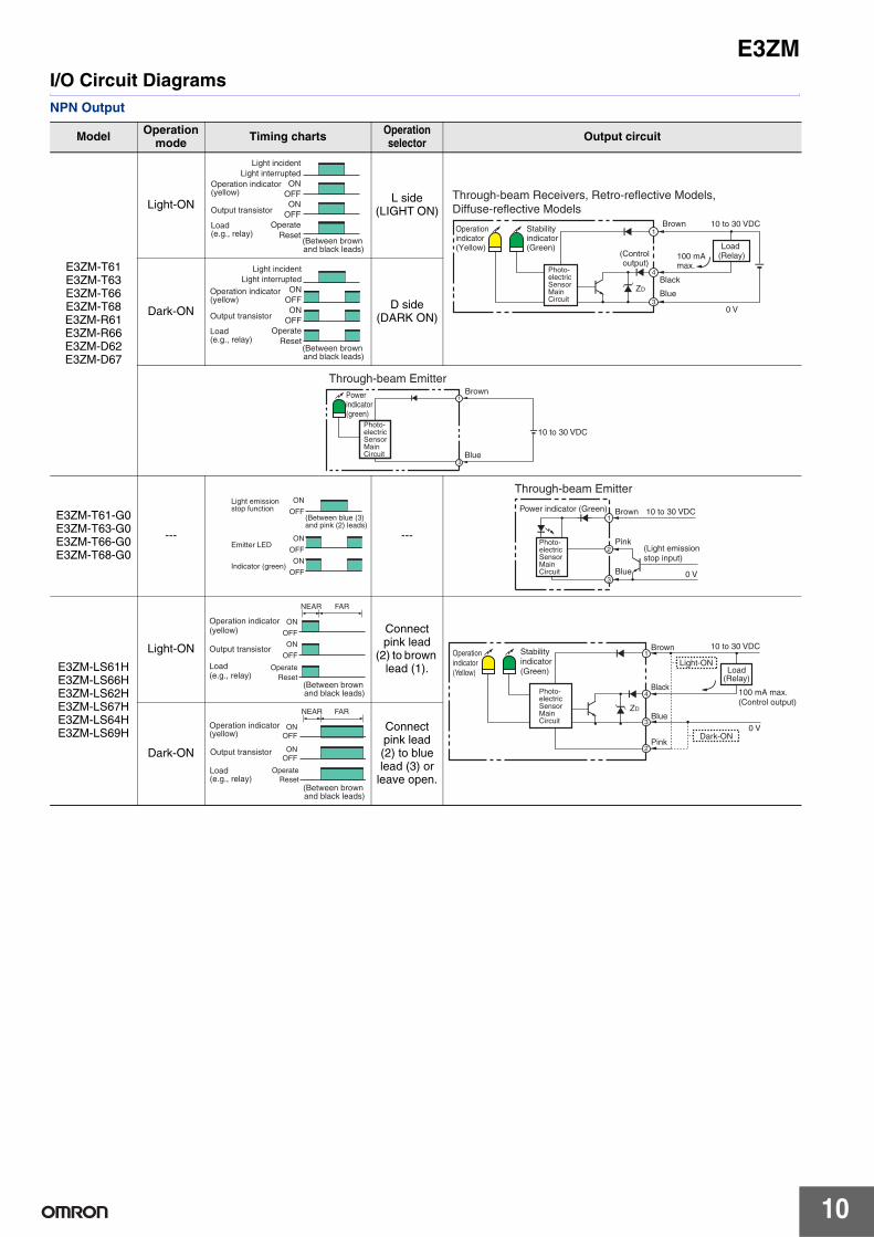
I/O Circuit DiagramsNPN Output
Model Operation mode Timing charts Operation
selector Output circuit
E3ZM-T61E3ZM-T63E3ZM-T66E3ZM-T68E3ZM-R61E3ZM-R66E3ZM-D62E3ZM-D67
Light-ON L side(LIGHT ON)
Dark-ON D side(DARK ON)
E3ZM-T61-G0E3ZM-T63-G0E3ZM-T66-G0E3ZM-T68-G0
--- ---
E3ZM-LS61HE3ZM-LS66HE3ZM-LS62HE3ZM-LS67HE3ZM-LS64HE3ZM-LS69H
Light-ON
Connect pink lead
(2) to brown lead (1).
Dark-ON
Connect pink lead (2) to blue lead (3) or
leave open.
Light incidentLight interrupted
ONOFFON
OFFOperate
Reset
Operation indicator (yellow)
(Between brown and black leads)
Output transistor
Load (e.g., relay)
4
3
1
0 V
ZD
Through-beam Receivers, Retro-reflective Models, Diffuse-reflective Models
10 to 30 VDCBrownOperation indicator(Yellow)
Stability indicator(Green)
Photo-electric Sensor Main Circuit
(Control output)
100 mAmax.
Black
Blue
Load (Relay)
Light incidentLight interrupted
ONOFFON
OFFOperate
Reset
Operation indicator (yellow)
(Between brown and black leads)
Output transistor
Load (e.g., relay)
3
1
Through-beam EmitterPower indicator (green)
Photo-electric Sensor Main Circuit
Brown
Blue
10 to 30 VDC
ON
OFF
ON
OFF
ON
OFF
Emitter LED
(Between blue (3) and pink (2) leads)
Indicator (green)
Light emissionstop function
1
2
3
Power indicator (Green) Brown
Pink
Blue
10 to 30 VDC
0 V
(Light emission stop input)
Photo-electric Sensor Main Circuit
Through-beam Emitter
NEAR FAR
ON
OFF
ON
OFF
OperateReset
Operation indicator (yellow)
Output transistor
Load (e.g., relay)
(Between brown and black leads) 4
3
2
110 to 30 VDCBrown
Black
Blue
Pink
100 mA max.(Control output)
Light-ON
Dark-ON
Operationindicator(Yellow)
Stabilityindicator(Green)
0 V
ZD
Load(Relay)
Photo-electric Sensor Main Circuit
NEAR FAR
ONOFF
ONOFF
OperateReset
Operation indicator (yellow)
Output transistor
Load(e.g., relay)
(Between brown and black leads)
E3ZM
11
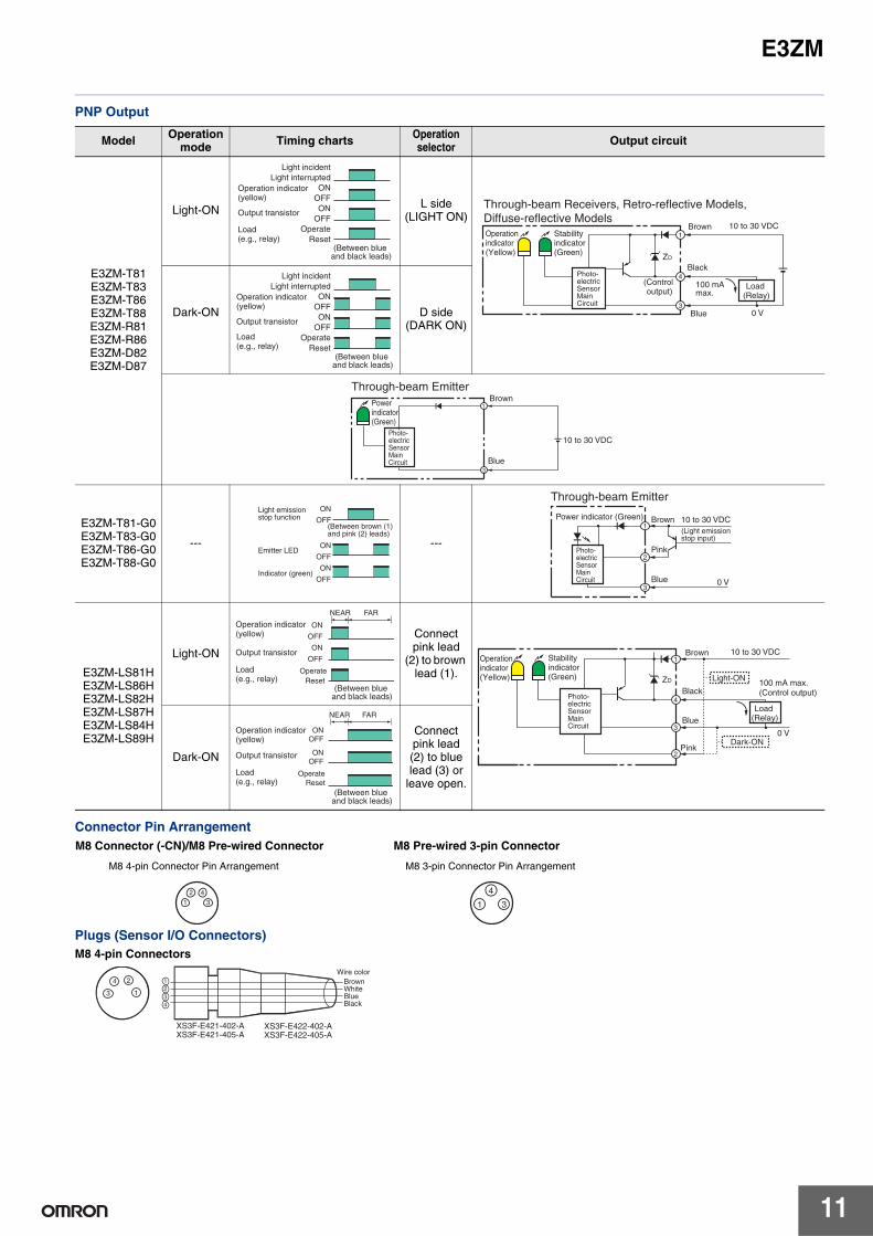
PNP Output
Connector Pin Arrangement
Plugs (Sensor I/O Connectors)
Model Operation mode Timing charts Operation
selector Output circuit
E3ZM-T81E3ZM-T83E3ZM-T86E3ZM-T88E3ZM-R81E3ZM-R86E3ZM-D82E3ZM-D87
Light-ON L side(LIGHT ON)
Dark-ON D side(DARK ON)
E3ZM-T81-G0E3ZM-T83-G0E3ZM-T86-G0E3ZM-T88-G0
--- ---
E3ZM-LS81HE3ZM-LS86HE3ZM-LS82HE3ZM-LS87HE3ZM-LS84HE3ZM-LS89H
Light-ON
Connect pink lead
(2) to brown lead (1).
Dark-ON
Connect pink lead (2) to blue lead (3) or
leave open.
Light incidentLight interrupted
ONOFFON
OFFOperate
Reset
Operation indicator (yellow)
(Between blue and black leads)
Output transistor
Load (e.g., relay)
4
1
30 V
ZD
Through-beam Receivers, Retro-reflective Models,Diffuse-reflective ModelsOperation indicator(Yellow)
Stability indicator(Green)
Photo-electric Sensor Main Circuit
(Control output)
10 to 30 VDCBrown
Black
Blue
100 mAmax.
Load (Relay)
Light incidentLight interrupted
ONOFFON
OFFOperate
Reset
Operation indicator (yellow)
(Between blue and black leads)
Output transistor
Load (e.g., relay)
3
1
Through-beam EmitterPower indicator (Green)
Photo-electric Sensor Main Circuit
Brown
Blue
10 to 30 VDC
ON
OFF
ON
OFF
ON
OFF
Emitter LED
Indicator (green)
Light emissionstop function
(Between brown (1) and pink (2) leads)
1
2
3
Power indicator (Green) Brown
Pink
Blue
10 to 30 VDC
0 V
(Light emissionstop input)
Through-beam Emitter
Photo-electric Sensor Main Circuit
NEAR FAR
ON
OFF
ON
OFF
OperateReset
Operation indicator (yellow)
Output transistor
Load (e.g., relay)
(Between blue and black leads) 4
3
2
1
Pink
100 mA max.(Control output)
Light-ON
Dark-ON0 V
ZD
Operation indicator(Yellow)
Stability indicator(Green)
Photo-electric Sensor Main Circuit
10 to 30 VDCBrown
Black
BlueLoad
(Relay)NEAR FAR
ONOFF
ONOFF
OperateReset
Operation indicator (yellow)
Output transistor
Load (e.g., relay)
(Between blue and black leads)
1
4
3
M8 Connector (-CN)/M8 Pre-wired Connector M8 Pre-wired 3-pin Connector
M8 4-pin Connector Pin Arrangement M8 3-pin Connector Pin Arrangement
1
2 43
M8 4-pin Connectors
24
13
1234
XS3F-E421-402-AXS3F-E421-405-A
XS3F-E422-402-AXS3F-E422-405-A
Brown White Blue Black
Wire color

E3ZM
12
NomenclatureSensors with Sensitivity Adjustment and Mode Selector SwitchThrough-beam ModelsE3ZM-T@@-D (Receiver)
Retro-reflective ModelsE3ZM-R@@
Diffuse-reflective ModelsE3ZM-D@@
Infinite Adjustment EmitterBGS Reflective ModelsE3ZM-LS@@H
Through-beam ModelsE3ZM-T@@-L (Emitter)
Stability indicator(Green)
Stability indicator (Green)
or Emitterpower supply indicator
(Green)
Operation selector
Operation indicator(Yellow)
Operation indicator(Yellow)Note: Emitter: No indicator
Sensitivity adjuster

E3ZM
13
Safety PrecautionsRefer to Warranty and Limitations of Liability.
This product is not designed or rated for ensuring safety of persons. Do not use it for such a purpose.
Do not use the product with voltage in excess of the rated voltage. Excess voltage may result in malfunction or fire.
Never use the product with an AC power supply. Otherwise, explosion may result.
When cleaning the product, do not apply a concentrated spray of water to one part of the product. Otherwise, parts may become damaged and the degree of protection may be degraded.
High-temperature environments may result in burn injury.
The following precautions must be observed to ensure safe operation of the Sensor.Operating EnvironmentDo not use the Sensor in an environment where explosive or flammable gas is present.
Connecting ConnectorsBe sure to hold the connector cover when inserting or removing the connector. If the XS3F is used, always tighten the connector cover by hand. Do not use pliers. If the tightening is insufficient, the degree of protection will not be maintained and the Sensor may become loose due to vibration. The appropriate tightening torque is 0.3 to 0.4 N·m.If other commercially available connectors are used, follow the recommended connector application conditions and recommended tightening torque specifications.
LoadDo not use a load that exceeds the rated load.
Low-temperature EnvironmentsDo not touch the metal surface with your bare hands when the temperature is low. Touching the surface may result in a cold burn.
Rotation Torque for Sensitivity Adjustment and Selector
SwitchAdjust with a torque of 0.06 N·m or less.
Oily EnvironmentsDo not use the Sensor in oily environments.
ModificationsDo not attempt to disassemble, repair, or modify the Sensor.
Outdoor UseDo not use the Sensor in locations subject to direct sunlight.
CleaningDo not use thinner, alcohol, or other organic solvents. Otherwise, the optical properties and degree of protection may be degraded.
WashingDo not use highly concentrated detergents. They may cause malfunction. Do not use high-pressure water spray in excess of the specifications.
Surface TemperatureBurn injury may occur. The Sensor surface temperature rises depending on application conditions, such as the surrounding temperature and the power supply voltage. Use caution when operating or washing the Sensor.
WARNING
CAUTION
Precautions for Safe Use

E3ZM
14
Do not install the Sensor in the following locations.(1)Locations subject to direct sunlight(2)Locations subject to condensation due to high humidity(3)Locations subject to corrosive gas(4)Locations where the Sensor may receive direct vibration or shock
Connecting and Mounting(1)The maximum power supply voltage is 30 VDC. Before turning the
power ON, make sure that the power supply voltage does not exceed the maximum voltage.
(2)Laying Sensor wiring in the same conduit or duct as high-voltage wires or power lines may result in malfunction or damage due to induction. As a general rule, wire the Sensor in a separate conduit or use shielded cable.
(3)Use an extension cable with a minimum thickness of 0.3 mm2 and less than 100 m long.
(4)Do not pull on the cable with excessive force.(5)Pounding the Photoelectric Sensor with a hammer or other tool
during mounting will impair water resistance. Also, use M3 screws.
(6)Mount the Sensor either using the bracket (sold separately) or on a flat surface.
(7)Be sure to turn OFF the power supply before inserting or removing the connector.
CleaningNever use thinner or other solvents. Otherwise, the Sensor surface may be dissolved.
Power SupplyIf a commercial switching regulator is used, ground the FG (frame ground) terminal.
Power Supply Reset TimeThe Sensor will be able to detect objects 100 ms after the power supply is tuned ON. Start using the Sensor 100 ms or more after turning ON the power supply. If the load and the Sensor are connected to separate power supplies, be sure to turn ON the Sensor first.
Turning OFF the Power SupplyOutput pulses may be generated even when the power supply is OFF. Therefore, it is recommended to first turn OFF the power supply for the load or the load line.
Load Short-circuit ProtectionThis Sensor is equipped with load short-circuit protection, but be sure to not short circuit the load. Be sure to not use an output current flow that exceeds the rated current. If a load short circuit occurs, the output will turn OFF, so check the wiring before turning ON the power supply again. The short-circuit protection circuit will be reset. The load short-circuit protection will operate when the current flow reaches 1.8 times the rated load current. When using a C load, use an inrush current of 1.8 times the rated load current or higher.
Water ResistanceDo not use the Sensor in water, rainfall, or outdoors.
When disposing of the Sensor, treat it as industrial waste.
Mounting Diagram
Resistance to Detergents, Disinfectants, and Chemicals• Performance is assured for typical detergents and disinfectants, but
performance may not be maintained for some detergents and disinfectants. Refer to the following table when using these agents.
• The E3ZM passed testing for resistance to detergents and disinfectants performed using the items in the following table. Refer to this table when considering use of detergents and disinfectants.
Note: The Sensor was immersed in the chemicals, detergents, and disinfectants listed above at the temperatures in the table for 240 hours and then passed an insulation resistance of 100 MΩ min.
Precautions for Correct Use
Category Product name Concen-tration
Temper-ature Time
Chemical
Sodium hydroxide (NaOH) 1.5% 70°C 240h
Potassium hydroxide (KOH) 1.5% 70°C 240h
Phosphoric acid (H3PO4) 2.5% 70°C 240h
Sodium hypochlorite (NaCIO) 0.3% 25°C 240h
Hydrogen peroxide (H2O2) 6.5% 25°C 240h
Alkaline foam detergent
P3-topax-66s (Manufactured by Ecolab) 3.0% 70°C 240h
Acidic foam detergent
P3-topax-56(Manufactured by Ecolab) 5.0% 70°C 240h
Disinfectant
P3-oxonia active 90 (Manufactured by Ecolab) 1.0% 25°C 240h
TEK121(Manufactured by ABC Com-pounding)
1.1% 25°C 240h
Mounting Bracket (sold separately)E39-L104
Use a mounting torque of 0.5 N·m max.
E3ZM
15
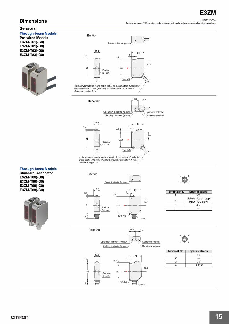
DimensionsSensors
(Unit: mm)Tolerance class IT16 applies to dimensions in this datasheet unless otherwise specified.
Through-beam ModelsPre-wired ModelsE3ZM-T61(-G0)E3ZM-T81(-G0)E3ZM-T63(-G0)E3ZM-T83(-G0)
Through-beam ModelsStandard ConnectorE3ZM-T66(-G0)E3ZM-T86(-G0)E3ZM-T68(-G0)E3ZM-T88(-G0)
Emitter
10.810.82121
32.8
12.7
3131
1.2
25.4
4 dia. vinyl-insulated round cable with 2 or 3 conductors (Conductor cross section: 0.2 mm2 (AWG24), Insulator diameter: 1.1 mm), Standard lengths: 2 m
Power indicator (green)
Emitter 6.4 dia.
Two, M3
25.4
4 dia. vinyl-insulated round cable with 3 conductors (Conductor cross section:0.2 mm2 (AWG24), Insulator diameter:1.1 mm), Standard length: 2 m
11.6 4.5
Stability indicator (green)
Operation Indicator (yellow)
Sensitivity adjuster
Operation selector
Two, M3
Receiver
21213
2.8
12.7
10.810.8
3131
1.2
Receiver 6.4 dia.
Two, M3
Power indicator (green)
M8×1
Emitter 6.4 dia.
3131
1.2
7
Emitter
10.810.82121
32.8
12.7
25.4
2 4
1 3
Terminal No. Specifications1 +V
2Light emission stop
input (-G0 only)3 0 V4 ---
Receiver 6.4 dia.
3131
1.2
7
10.810.8
Stability indicator (green)
Operation Indicator (yellow)
Sensitivity adjuster
Operation selector
11.6 4.5
21213
2.8
12.7
25.4
M8×1Two, M3
Receiver
2 4
1 3
Terminal No. Specifications1 +V2 ---3 0 V4 Output

E3ZM
16
11.6 4.5
Stability indicator (green)
Operation Indicator (yellow)
Sensitivity adjuster*
Operation selector*
*No sensitivity adjuster and operation selector with BGS reflective model
4 dia. vinyl-insulated round cable with 3 conductors (Conductor cross section:0.2 mm2 (AWG24), Insulator diameter:1.1 mm), Standard length: 2 m
25.4
21213
2.8
16.2
10.810.8
3131 7
1.2 Receiver 6.4 dia.
Emitter 6.4 dia.
Two, M3
Retro-reflective ModelsPre-wired ModelsE3ZM-R61E3ZM-R81
Diffuse-reflective ModelsStandard ConnectorE3ZM-D62E3ZM-D82
BGS Reflective ModelsPre-wired ModelsE3ZM-LS61HE3ZM-LS62HE3ZM-LS64HE3ZM-LS81HE3ZM-LS82HE3ZM-LS84H
Receiver 6.4 dia.
Emitter 6.4 dia.
3131 7
7
1.2
*No sensitivity adjuster and operation selector with BGS reflective model
Stability indicator (green)
Operation Indicator (yellow)
Sensitivity adjuster*
Operation selector*
M8×1Two, M3
11.6 4.5
10.8 10.8
25.4
21213
2.8
16.2
Retro-reflective ModelsStandard ConnectorE3ZM-R66E3ZM-R86
Diffuse-reflective ModelsStandard ConnectorE3ZM-D67E3ZM-D87
BGS Reflective ModelsStandard ConnectorE3ZM-LS66HE3ZM-LS67HE3ZM-LS69HE3ZM-LS86HE3ZM-LS87HE3ZM-LS89H
Receiver 6.4 dia.
Emitter 6.4 dia.
3131 7
7
1.2
*No sensitivity adjuster and operation selector with BGS reflective model
Stability indicator (green)
Operation Indicator (yellow)
Sensitivity adjuster*
Operation selector*
M8×1Two, M3
11.6 4.5
10.8 10.8
25.4
21213
2.8
16.2
Receiver 6.4 dia.
Emitter 6.4 dia.
3131 7
7
1.2
*No sensitivity adjuster and operation selector with BGS reflective model
Stability indicator (green)
Operation Indicator (yellow)
Sensitivity adjuster*
Operation selector*
M8×1Two, M3
11.6 4.5
10.8 10.8
25.4
21213
2.8
16.2
2 4
1 3
Terminal No. Specifications1 +V2 ---3 0 V4 Output
Terms and Conditions of Sale1. Offer; Acceptance. These terms and conditions (these "Terms") are deemed
part of all quotes, agreements, purchase orders, acknowledgments, price lists,catalogs, manuals, brochures and other documents, whether electronic or inwriting, relating to the sale of products or services (collectively, the "Products")by Omron Electronics LLC and its subsidiary companies (“Omron”). Omronobjects to any terms or conditions proposed in Buyer’s purchase order or otherdocuments which are inconsistent with, or in addition to, these Terms.
2. Prices; Payment Terms. All prices stated are current, subject to change with-out notice by Omron. Omron reserves the right to increase or decrease priceson any unshipped portions of outstanding orders. Payments for Products aredue net 30 days unless otherwise stated in the invoice.
3. Discounts. Cash discounts, if any, will apply only on the net amount of invoicessent to Buyer after deducting transportation charges, taxes and duties, and willbe allowed only if (i) the invoice is paid according to Omron’s payment termsand (ii) Buyer has no past due amounts.
4. Interest. Omron, at its option, may charge Buyer 1-1/2% interest per month orthe maximum legal rate, whichever is less, on any balance not paid within thestated terms.
5. Orders. Omron will accept no order less than $200 net billing. 6. Governmental Approvals. Buyer shall be responsible for, and shall bear all
costs involved in, obtaining any government approvals required for the impor-tation or sale of the Products.
7. Taxes. All taxes, duties and other governmental charges (other than generalreal property and income taxes), including any interest or penalties thereon,imposed directly or indirectly on Omron or required to be collected directly orindirectly by Omron for the manufacture, production, sale, delivery, importa-tion, consumption or use of the Products sold hereunder (including customsduties and sales, excise, use, turnover and license taxes) shall be charged toand remitted by Buyer to Omron.
8. Financial. If the financial position of Buyer at any time becomes unsatisfactoryto Omron, Omron reserves the right to stop shipments or require satisfactorysecurity or payment in advance. If Buyer fails to make payment or otherwisecomply with these Terms or any related agreement, Omron may (without liabil-ity and in addition to other remedies) cancel any unshipped portion of Prod-ucts sold hereunder and stop any Products in transit until Buyer pays allamounts, including amounts payable hereunder, whether or not then due,which are owing to it by Buyer. Buyer shall in any event remain liable for allunpaid accounts.
9. Cancellation; Etc. Orders are not subject to rescheduling or cancellationunless Buyer indemnifies Omron against all related costs or expenses.
10. Force Majeure. Omron shall not be liable for any delay or failure in deliveryresulting from causes beyond its control, including earthquakes, fires, floods,strikes or other labor disputes, shortage of labor or materials, accidents tomachinery, acts of sabotage, riots, delay in or lack of transportation or therequirements of any government authority.
11. Shipping; Delivery. Unless otherwise expressly agreed in writing by Omron:a. Shipments shall be by a carrier selected by Omron; Omron will not drop ship
except in “break down” situations.b. Such carrier shall act as the agent of Buyer and delivery to such carrier shall
constitute delivery to Buyer;c. All sales and shipments of Products shall be FOB shipping point (unless oth-
erwise stated in writing by Omron), at which point title and risk of loss shallpass from Omron to Buyer; provided that Omron shall retain a security inter-est in the Products until the full purchase price is paid;
d. Delivery and shipping dates are estimates only; ande. Omron will package Products as it deems proper for protection against nor-
mal handling and extra charges apply to special conditions.12. Claims. Any claim by Buyer against Omron for shortage or damage to the
Products occurring before delivery to the carrier must be presented in writingto Omron within 30 days of receipt of shipment and include the original trans-portation bill signed by the carrier noting that the carrier received the Productsfrom Omron in the condition claimed.
13. Warranties. (a) Exclusive Warranty. Omron’s exclusive warranty is that theProducts will be free from defects in materials and workmanship for a period oftwelve months from the date of sale by Omron (or such other period expressedin writing by Omron). Omron disclaims all other warranties, express or implied.(b) Limitations. OMRON MAKES NO WARRANTY OR REPRESENTATION,EXPRESS OR IMPLIED, ABOUT NON-INFRINGEMENT, MERCHANTABIL-
ITY OR FITNESS FOR A PARTICULAR PURPOSE OF THE PRODUCTS.BUYER ACKNOWLEDGES THAT IT ALONE HAS DETERMINED THAT THEPRODUCTS WILL SUITABLY MEET THE REQUIREMENTS OF THEIRINTENDED USE. Omron further disclaims all warranties and responsibility ofany type for claims or expenses based on infringement by the Products or oth-erwise of any intellectual property right. (c) Buyer Remedy. Omron’s sole obli-gation hereunder shall be, at Omron’s election, to (i) replace (in the formoriginally shipped with Buyer responsible for labor charges for removal orreplacement thereof) the non-complying Product, (ii) repair the non-complyingProduct, or (iii) repay or credit Buyer an amount equal to the purchase price ofthe non-complying Product; provided that in no event shall Omron be responsi-ble for warranty, repair, indemnity or any other claims or expenses regardingthe Products unless Omron’s analysis confirms that the Products were prop-erly handled, stored, installed and maintained and not subject to contamina-tion, abuse, misuse or inappropriate modification. Return of any Products byBuyer must be approved in writing by Omron before shipment. Omron Compa-nies shall not be liable for the suitability or unsuitability or the results from theuse of Products in combination with any electrical or electronic components,circuits, system assemblies or any other materials or substances or environ-ments. Any advice, recommendations or information given orally or in writing,are not to be construed as an amendment or addition to the above warranty.See http://www.omron247.com or contact your Omron representative for pub-lished information.
14. Limitation on Liability; Etc. OMRON COMPANIES SHALL NOT BE LIABLEFOR SPECIAL, INDIRECT, INCIDENTAL, OR CONSEQUENTIAL DAMAGES,LOSS OF PROFITS OR PRODUCTION OR COMMERCIAL LOSS IN ANYWAY CONNECTED WITH THE PRODUCTS, WHETHER SUCH CLAIM ISBASED IN CONTRACT, WARRANTY, NEGLIGENCE OR STRICT LIABILITY.Further, in no event shall liability of Omron Companies exceed the individualprice of the Product on which liability is asserted.
15. Indemnities. Buyer shall indemnify and hold harmless Omron Companies andtheir employees from and against all liabilities, losses, claims, costs andexpenses (including attorney's fees and expenses) related to any claim, inves-tigation, litigation or proceeding (whether or not Omron is a party) which arisesor is alleged to arise from Buyer's acts or omissions under these Terms or inany way with respect to the Products. Without limiting the foregoing, Buyer (atits own expense) shall indemnify and hold harmless Omron and defend or set-tle any action brought against such Companies to the extent based on a claimthat any Product made to Buyer specifications infringed intellectual propertyrights of another party.
16. Property; Confidentiality. Any intellectual property in the Products is the exclu-sive property of Omron Companies and Buyer shall not attempt to duplicate itin any way without the written permission of Omron. Notwithstanding anycharges to Buyer for engineering or tooling, all engineering and tooling shallremain the exclusive property of Omron. All information and materials suppliedby Omron to Buyer relating to the Products are confidential and proprietary,and Buyer shall limit distribution thereof to its trusted employees and strictlyprevent disclosure to any third party.
17. Export Controls. Buyer shall comply with all applicable laws, regulations andlicenses regarding (i) export of products or information; (iii) sale of products to“forbidden” or other proscribed persons; and (ii) disclosure to non-citizens ofregulated technology or information.
18. Miscellaneous. (a) Waiver. No failure or delay by Omron in exercising any rightand no course of dealing between Buyer and Omron shall operate as a waiverof rights by Omron. (b) Assignment. Buyer may not assign its rights hereunderwithout Omron's written consent. (c) Law. These Terms are governed by thelaw of the jurisdiction of the home office of the Omron company from whichBuyer is purchasing the Products (without regard to conflict of law princi-ples). (d) Amendment. These Terms constitute the entire agreement betweenBuyer and Omron relating to the Products, and no provision may be changedor waived unless in writing signed by the parties. (e) Severability. If any provi-sion hereof is rendered ineffective or invalid, such provision shall not invalidateany other provision. (f) Setoff. Buyer shall have no right to set off any amountsagainst the amount owing in respect of this invoice. (g) Definitions. As usedherein, “including” means “including without limitation”; and “Omron Compa-nies” (or similar words) mean Omron Corporation and any direct or indirectsubsidiary or affiliate thereof.
Certain Precautions on Specifications and Use1. Suitability of Use. Omron Companies shall not be responsible for conformity
with any standards, codes or regulations which apply to the combination of theProduct in the Buyer’s application or use of the Product. At Buyer’s request,Omron will provide applicable third party certification documents identifyingratings and limitations of use which apply to the Product. This information byitself is not sufficient for a complete determination of the suitability of the Prod-uct in combination with the end product, machine, system, or other applicationor use. Buyer shall be solely responsible for determining appropriateness ofthe particular Product with respect to Buyer’s application, product or system.Buyer shall take application responsibility in all cases but the following is anon-exhaustive list of applications for which particular attention must be given:(i) Outdoor use, uses involving potential chemical contamination or electricalinterference, or conditions or uses not described in this document.(ii) Use in consumer products or any use in significant quantities. (iii) Energy control systems, combustion systems, railroad systems, aviationsystems, medical equipment, amusement machines, vehicles, safety equip-ment, and installations subject to separate industry or government regulations. (iv) Systems, machines and equipment that could present a risk to life or prop-erty. Please know and observe all prohibitions of use applicable to this Prod-uct. NEVER USE THE PRODUCT FOR AN APPLICATION INVOLVING SERIOUSRISK TO LIFE OR PROPERTY OR IN LARGE QUANTITIES WITHOUTENSURING THAT THE SYSTEM AS A WHOLE HAS BEEN DESIGNED TO
ADDRESS THE RISKS, AND THAT THE OMRON’S PRODUCT IS PROP-ERLY RATED AND INSTALLED FOR THE INTENDED USE WITHIN THEOVERALL EQUIPMENT OR SYSTEM.
2. Programmable Products. Omron Companies shall not be responsible for theuser’s programming of a programmable Product, or any consequence thereof.
3. Performance Data. Data presented in Omron Company websites, catalogsand other materials is provided as a guide for the user in determining suitabil-ity and does not constitute a warranty. It may represent the result of Omron’stest conditions, and the user must correlate it to actual application require-ments. Actual performance is subject to the Omron’s Warranty and Limitationsof Liability.
4. Change in Specifications. Product specifications and accessories may bechanged at any time based on improvements and other reasons. It is our prac-tice to change part numbers when published ratings or features are changed,or when significant construction changes are made. However, some specifica-tions of the Product may be changed without any notice. When in doubt, spe-cial part numbers may be assigned to fix or establish key specifications foryour application. Please consult with your Omron’s representative at any timeto confirm actual specifications of purchased Product.
5. Errors and Omissions. Information presented by Omron Companies has beenchecked and is believed to be accurate; however, no responsibility is assumedfor clerical, typographical or proofreading errors or omissions.

CSM_E3ZM_DS_E_5_2 07/10 Note: Specifications are subject to change. © 2010 Omron Electronics LLC
OMRON CANADA, INC. • HEAD OFFICEToronto, ON, Canada • 416.286.6465 • 866.986.6766www.omron247.com
OMRON ELETRÔNICA DO BRASIL LTDA • HEAD OFFICESão Paulo, SP, Brasil • 55.11.2101.6300 • www.omron.com.br
OMRON ELECTRONICS MEXICO SA DE CV • HEAD OFFICEApodaca, N.L. • 52.811.156.99.10 • 001.800.556.6766 • [email protected]
OMRON ARGENTINA • SALES OFFICECono Sur • 54.11.4783.5300
OMRON CHILE • SALES OFFICESantiago • 56.9.9917.3920
OTHER OMRON LATIN AMERICA SALES54.11.4783.5300
OMRON ELECTRONICS LLC • THE AMERICAS HEADQUARTERS • Schaumburg, IL USA • 847.843.7900 • 800.556.6766 • www.omron247.com
OMRON EUROpE B.V. Wegalaan 67-69, NL-2132 JD, Hoofddorp, The Netherlands. Tel: +31 (0) 23 568 13 00 Fax: +31 (0) 23 568 13 88 www.industrial.omron.eu