Compact magnetic drive pumps for OEM, aquarium, and …panworldamericas.com/pdf/pan world...
20
Transcript of Compact magnetic drive pumps for OEM, aquarium, and …panworldamericas.com/pdf/pan world...


• Compact magnetic drive pumps for OEM, aquarium, and process
applications.
• Offering ceramic or Sic bearing and spindles for wearing
components.
5
2
60Hz
Tota
l hea
d (f
t)
Discharge flow (GPM)
10
20
15
25
30
35
40
45
0 4 6 8 10 12 14 16 18 20
3PX/10PX
5PX-Z
30PX
40PX
50PX
50PX-Z
100PX-Z
100PX-ZZ
100PX
100PX-X
50PX-X
PX Series ( PPG, PVDF, or ETFE )
Specification table
NH-3PX/3PX-NNH-5PX-Z/5PX-Z-NNH-10PX/10PX-NNH-30PX/30PX-N/30PX-FNH-40PX/40PX-N/40PX-FNH-50PX-Z/50PX-Z-N/50PX-Z-FNH-50PX/50PX-N/50PX-FNH-50PX-X/50PX-X-N/50PX-X-FNH-100PX-Z/100PX-Z-N/100PX-Z-FNH-100PX/100PX-N/100PX-FNH-100PX-X/100PX-X-N/100PX-X-FNH-100PX-ZZ/100PX-ZZ-N/100PX-ZZ-F
Fitting size(") Performance ft-GPM, 60HzModel Hose
InxOutlet9/16x9/16
9/16x9/16
9/16x9/16
9/16x9/16
11/16x11/16
11/16x11/16
13/16x13/16
1x1
11/16x11/16
13/16x13/16
1x1
13/16x13/16
NPT threadInxOutlet1/2x1/2
1/2x1/2
1/2x1/2
3/4x3/4
3/4x3/4
3/4x3/4
3/4x3/4
1x1
3/4x3/4
3/4x3/4
1x1
3/4x3/4
Max total head-max discharge
6.6-3.0
9.2-1.9
6.6-3.0
10.2-4.8
13.5-7.9
22.0-2.9
16.4-9.8
13.0-13.2
36.1-4.8
20.7-13.2
13.1-21.1
44.3-6.3
Specified head-specified discharge
3.3-2.0
4.9-1.1
3.3-2.0
4.9-3.4
6.6-5.8
13.1-2.1
8.2-6.3
6.6-10.6
19.7-3.4
13.1-8.2
6.6-15.9
19.7-5.3
MotorOutput xInput(W)5x20
5x21
5x20
10x30
20x45
20x55
45x90
45x90
45x95
65x120
65x165
65x200
100~120
100~120
100~120
100~120
100~120
100~120
100~120
100~120
100~120
100~120
100~120
100~120
(V)Voltage
2.2
2.2
2.2
3.7
4.4
4.8
6.6
6.6
6.6
7.7
7.7
7.7
Net
(lb)weight
Pump performance curve

L4.0
5.7
H3.6
3.6
W2.8
2.9
c2.8
2.9
b1.2
1.2
e1.8
1.8
d2.4
2.4
f1.1
1.2
g0.7
0.7
ModelNH-3PXNH-5PX-ZNH-10PX
Model
NH-40PXNH-30PX
NH-50PX-Z
W
3.73.7
3.7
H4.54.54.9
L7.88.38.9
a1.21.21.2
b
2.02.0
2.0
c4.65.25.3
d
3.33.3
3.3
e
2.22.2
2.2
f1.51.51.6
g
1.10.8
1.5
f1.9
1.91.62.0
2.01.5
Model
NH-100PX-Z
NH-50PX
NH-100PX
NH-50PX-X
NH-100PX-XNH-100PX-ZZ
L9.7
10.39.3
10.0
10.69.6
H5.1
5.15.1
5.3
5.35.1
c6.7
6.76.06.9
6.96.3
g
1.2
1.2
1.51.0
1.01.8
W4.74.7
4.74.7
4.74.7
d3.93.93.93.93.93.9
e2.42.42.42.42.42.4
a1.61.61.61.61.61.6
b2.52.52.52.52.52.5
ab
c
L
f
Wd
g
eH
dc
H
W
e
f g
L
a
b
a
b
L
f
H
e
d
W
g
( inch )
( inch )( inch )
NH-3PX, 5PX-Z, 10PX NH-3PX-N, 5PX-Z-N, 10PX-N
NH-50PX, 50PX-X, 100PX-Z, 100PX, 100PX-X, 100PX-ZZ, NH-50PX-F, 50PX-X-F, 100PX-Z-F, 100PX-F, 100PX-X-F, 100PX-ZZ-FNH-50PX-N, 50PX-X-N, 100PX-Z-N, 100PX-N, 100PX-X-N, 100PX-ZZ-N
NH-30PX, 40PX, 50PX-ZNH-30PX-F, 40PX-F, 50PX-Z-FNH-30PX-N, 40PX-N, 50PX-Z-N
Hose, NPT thread Hose, NPT thread
Hose, NPT thread
Installation dimensions
Model identification
N H - 3 0 P X - N - H - 1(5) (4) (3) (2) (1)
Model
Series
Supply voltage : 1 100-110V 2 220-240V
Pipe connection : H Hose : T NPT thread
Material : Without PPG N PVDF F ETFE

Tota
l hea
d (f
t)
Discharge flow (GPM)
2
0 1
5PX-Z-D5PX-D
10PX-D 30PX-D
40PX-D
50PX-Z-D
2 3 4 5 6 7
4
8
6
12
10
14
16
18
8
• Available in 12 and 24 VDC.
• Wetted end materials in PP, PVDF or ETFE to meet customer requirements.
• Outputs for variable speed control and speed monitoring.
• Motor efficiency is double that of conventional AC models.
• Rugged metal construction.
PX-D SeriesMagnetic drive pump with brushless DC motor
Specification table
Pump performance curve
Fitting size ( " )
Polypropylene/PVDF/ETFE
NH-5PX-D / 5PX-D-N
NH-10PX-D / 10PX-D-N
NH-5PX-Z-D / 5PX-Z-D-N
NH-30PX-D / 30PX-D-N / 30PX-D-F
NH-40PX-D / 40PX-D-N / 40PX-D-F
NH-50PX-Z-D / 50PX-Z-D-N / 50PX-Z-D-F
Model
Wetted end Hose
InxOutlet
9/16x9/16
9/16x9/16
9/16x9/16
9/16x9/16
11/16x11/16
11/16x11/16
NPT thread
InxOutlet
1/2x1/2
1/2x1/2
1/2x1/2
3/4x3/4
3/4x3/4
3/4x3/4
6.2-3.0/4,000
7.9-3.4/3,700
11.5-3.0/3,700
11.8-5.8/3,500
12.8-7.9/3,500
16.4-3.6/3,000
Maximum Performance
Head -Discharge flow / Speed
( ft - GPM / rpm )
Net
(lb)
weight
1.3
1.3
1.3
2.6
2.7
3.2
12,24
12,24
12,24
24
24
24
Voltage(V)
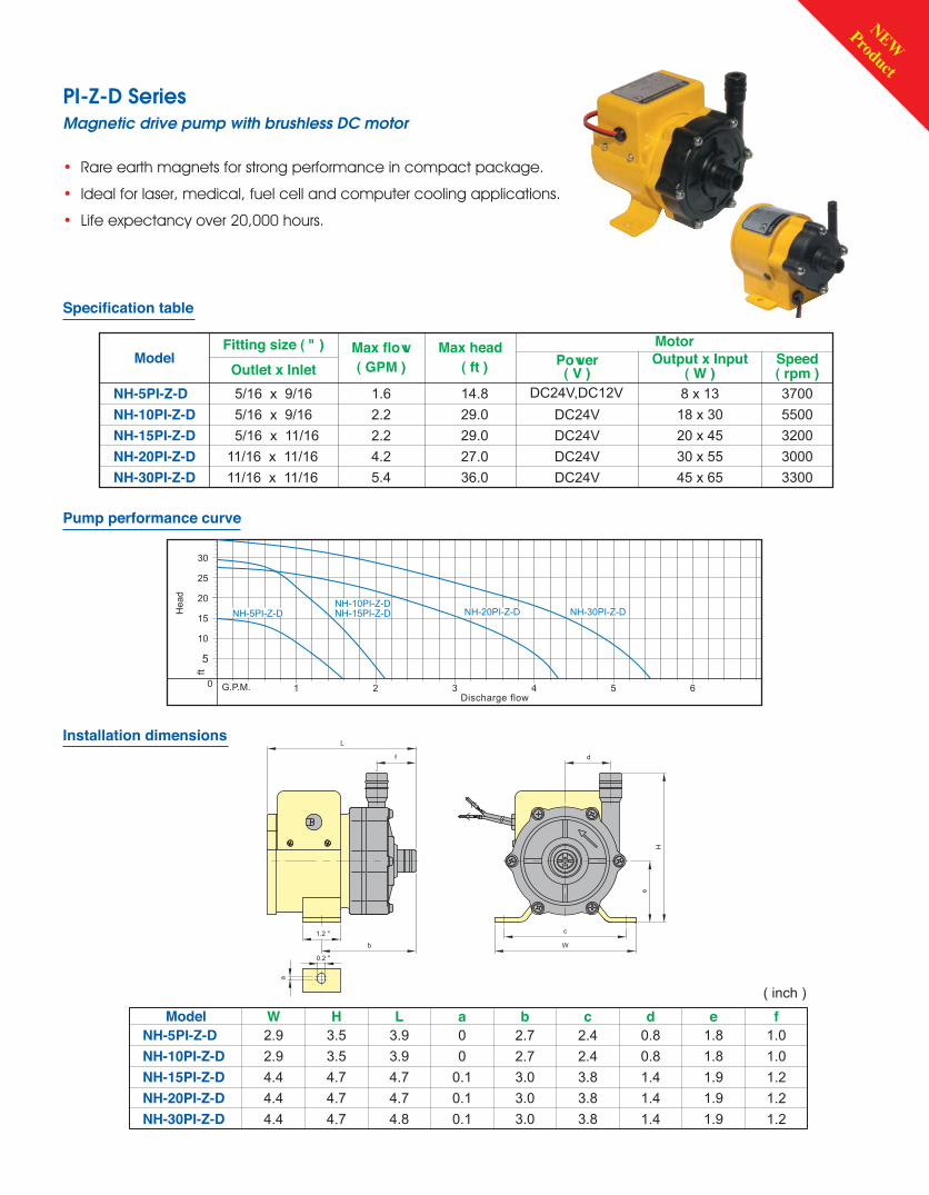
• Rare earth magnets for strong performance in compact package.
• Ideal for laser, medical, fuel cell and computer cooling applications.
• Life expectancy over 20,000 hours.
PI-Z-D SeriesMagnetic drive pump with brushless DC motor
Model( inch )
MotorMax head( ft )Model
NH-15PI-Z-D
NH-30PI-Z-DNH-20PI-Z-D
NH-5PI-Z-DNH-10PI-Z-D
NH-30PI-Z-DNH-20PI-Z-DNH-15PI-Z-D
NH-5PI-Z-DNH-10PI-Z-D
Outlet x InletFitting size ( " )
5/16 x 11/16
11/16 x 11/1611/16 x 11/16
5/16 x 9/165/16 x 9/16
( rpm )Speed
3200
33003000
37005500
Output x Input( W )
20 x 45
45 x 6530 x 55
8 x 1318 x 30
( GPM )Max flow
2.2
1.6
5.44.2
2.229.0
36.027.0
14.829.0
Power( V )
DC24V,DC12V
DC24VDC24V
DC24VDC24V
L3.9
4.74.74.8
3.9
H
4.74.7
3.5
4.73.5
d
1.41.41.4
0.80.8
b
3.03.03.0
2.72.7
a
0.10.10.1
00
c
3.83.83.8
2.42.4
f
1.21.2
1.0
1.21.0
e
1.91.9
1.8
1.91.8
W2.9
4.42.9
4.44.4
b
L
f
0.2 "
c
W
d
H
e
a
1.2 "
30
25
15
20
10
ft
Hea
d
5
Discharge flow1G.P.M.0 2 3 4 5 6
NH-5PI-Z-D NH-15PI-Z-DNH-10PI-Z-D
NH-20PI-Z-D NH-30PI-Z-D
Specification table
Pump performance curve
Installation dimensions
NEWProduct

2
Nominal speed : 3,200 r.p.m
60Hz
0
5
Tota
l hea
d (f
t)
Discharge flow (GPM)4 86 1210 1614 2018 22 24 26 3028
10
15
20
25
35
30
40
55
45
50
70
60
65
80
75
85
150PS
200PS-Z
200PS
250PS
300PS
• PP wetted end materials for OEM, aquarium and
general process applications.
• ETFE wetted end materials for hazardous chemical transfer.
• Heavy duty motor construction for long life.
PS Series
Specification table
Pump performance curve
Performance ft-GPM, 60HZFitting size (") Model
MotorOutput xInput(W)90-170
150-290
150-290
250-390
330-460
13
18
18
20
26
Net
(lb)weight
NH-150PS/150PS-FNH-200PS-Z/200PS-Z-FNH-200PS/200PS-FNH-250PS/250PS-FNH-300PS/300PS-F
Nominal speed 2,700/3,200 r.p.m
HoseInxOutlet
1x1
1x1
1x1
1x1
1x13/16
1x1
1x1
1x1
1x1
1x3/4
NPT threadInxOutlet
Max total head-max discharge
27.0-18.5
52.5-9.5
39.0-29.0
46.0-31.5
82.0-13.0
Specified head-specified discharge
13.0-11.9
26.0-7.9
24.5-18.5
29.5-21.0
68.9-13.0
100~120
100~120
100~120
100~120
100~120
Voltage(V)
Note:Performance curves are for water. Consult PWA for higher Specific gravity chemicals.

Model identification
N H - 2 0 0 P S - F - H - 1(5) (4) (3) (2) (1)
Model
Series
Supply voltage : 1 100-110V 2 220-240V
Pipe connection : H Hose : T NPT thread
Material : Without PPG N PVDF F ETFE
Installation dimensions
b
a
L
c
f
e
W
H
g
d
NH-300PSNH-250PSNH-200PS-Z
ModelNH-150PS
( inch )
NH-200PS
L11.8
14.014.414.4
14.0
H
6.56.5
6.5
6.56.5
d
4.34.34.3
3.94.3
b
3.93.93.9
2.53.9
a
2.82.82.8
2.52.8
c
8.18.18.5
7.88.5
f
2.82.8
2.8
2.82.8
e
2.62.6
2.6
2.62.6
W4.7
6.16.1
6.16.1
g
43.543.5
43.5
43.543.5
NH-150PS, 200PS, 250PS, 300PSNH-150PS-F, 200PS-F, 250PS-F, 300PS-F
Hose, NPT thread

• PPG wetted end material.
• 9 models with flow rates up to 370 GPM and discharge head of 121 ft.
• Able to handle many types of chemical and temperature of up to 70 ˚C.
PW Series (PPG)General purpose magnetic drive pumps
Specification table
60HzModel
NH-400PW
NH-401PW
NH-402PW
NH-403PW
NH-405PW
* NH-655PW
* NH-657PW
* NH-6510PW
* NH-6515PW
1 1/2
1 1/2
1 1/2
1 1/2
1 1/2
2 1/2
2 1/2
2 1/2
2 1/2
Fitting size(")Outlet
1 1/2
1 1/2
2
2
2
3
3
3
3
Inlet1.11.31.51.11.31.51.11.31.51.11.31.51.11.31.51.11.31.51.11.31.51.11.31.51.11.31.5
Pump performance at specified point (ft GPM)
Specific Gravity22.0-42.025.5-37.019.5-34.037.5-66.030.0-52.524.5-52.546.0-79.045.5-70.047.5-58.062.0-74.055.5-74.048.0-89.5
78.5-111.078.5-103.065.5-103.051.0-158.5
------
59.0-198.054.0-166.043.5-200.576.5-211.064.0-203.559.5-177.096.5-272.0
103.0-171.580.5-224.5
NEMA-C motor
Output(HP)-Frame size
46
66
99
117
141
242
264
286
308
Netweight
(lb)
56C
56C
143TC
145TC2 -
143TC
145TC3 -
182TC
184TC5 -
182TC
184TC5 -
213TC
215TC7.5 -
213TC
215TC10 -
254TC
256TC15 -
1 -
1/2 -
Model identification
N H - 4 0 0 P W - C V - L(5) (4) (3) (2) (1)
Model
Series
Impeller size : S S.G=1.0 L S.G=1.1 M S.G=1.3 H S.G=1.5
V FKM N NBR E EPDM
C : Carbon bearingR : Rulon bearingA : Oxide Almina ceramic bearing
O ring
Note: * These models are with flanges only.

Nominal speed : 3,440 r.p.m
60Hz
0
Tota
l hea
d (f
t)
Discharge flow (GPM)
400PW
100
10
401PW
402PW
50 150 200 250 300 350
20
4030
6050
8070
90100110120130140
403PW
405PW
655PW657PW
6510PW
6515PW
402PW(S)
403PW(S)
Parts List
PW series performance curve
Part namePW Series
2
6
5
4
3
1
7
8
1. Casing
2. Holder
3. Bearing
4. Thrust pad
5. Spindle
6. O ring
7. O ring
8. Bracket
RVCV AV CN AN
PPG
ETFE
Ceramic
Ceramic
Grey cast iron
H.D.Carbon Rulon Ceramic H.D.
Carbon Ceramic
FKM
FKM
NBR
NBRImpeller size : S S.G=1.0 L S.G=1.1 M S.G=1.3 H S.G=1.5
V FKM N NBR E EPDM
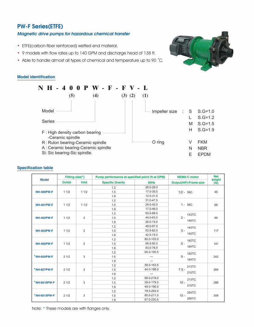
• ETFE(carbon-fiber reinforced) wetted end material.
• 9 models with flow rates up to 140 GPM and discharge head of 138 ft.
• Able to handle almost all types of chemical and temperature up to 90 ˚C.
Model identification
N H - 4 0 0 P W - F - F V - L(5) (4) (3) (2) (1)
Model
Series
Impeller size : S S.G=1.0 L S.G=1.2 M S.G=1.5 H S.G=1.9
V FKM N NBR E EPDM
F : High density carbon bearing -Ceramic spindleR : Rulon bearing-Ceramic spindleA : Ceramic bearing-Ceramic spindleSi : Sic bearing-Sic spindle.
O ring
Specification table
60HzModel
1 1/2
1 1/2
1 1/2
1 1/2
1 1/2
2 1/2
2 1/2
2 1/2
2 1/2
Fitting size(")Outlet
1 1/2
1 1/2
2
2
2
3
3
3
3
InletPump performance at specified point (ft at GPM)
Specific Gravity
NEMA-C motor
Output(HP)-Frame size
46
66
99
117
141
242
264
286
308
Netweight
(lb)
NH-400PW-F
NH-401PW-F
NH-402PW-F
NH-403PW-F
NH-405PW-F
* NH-655PW-F
* NH-657PW-F
* NH-6510PW-F
* NH-6515PW-F
1.21.51.91.21.51.91.21.51.91.21.51.91.21.51.91.21.51.91.21.51.91.21.51.91.21.51.9
26.0-29.017.0-35.512.5-31.531.0-47.529.0-42.017.0-46.050.5-68.544.0-63.526.0-74.049.0-87.053.5-82.042.5-74.0
80.0-103.066.5-92.563.0-76.5
65.0-105.5------
59.0-163.544.0-198.0
---68.0-219.059.0-179.549.0-190.078.5-293.085.0-211.067.0-220.5
56C
56C
143TC
145TC2 -
143TC
145TC3 -
182TC
184TC5 -
182TC
184TC5 -
213TC
215TC7.5 -
213TC
215TC10 -
254TC
256TC15 -
1 -
1/2 -
PW-F Series(ETFE)Magnetic drive pumps for hazardous chemical transfer
Note: * These models are with flanges only.
Nominal speed : 3,440 r.p.m
0
Tota
l hea
d (f
t)
Discharge flow (GPM)
60Hz
100
10
50 150 200 250 300 350
20
4030
6050
8070
90100110120130140
6515PW-F
400PW-F
402PW-F
403PW-F
405PW-F
657PW-F
6510PW-F655PW-F
402PW-F(S)
403PW-F(S)
401PW-F
401PW-F(S)
400PW-F(S)
Parts List
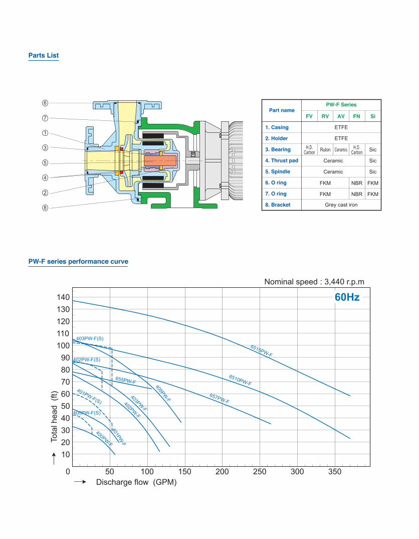
PW-F series performance curve
Part namePW-F Series
2
6
5
4
3
1
7
8
1. Casing
2. Holder
3. Bearing
4. Thrust pad
5. Spindle
6. O ring
7. O ring
8. Bracket
RVFV AV FN Si
ETFE
ETFE
Grey cast iron
H.D.Carbon Rulon Ceramic H.D.
Carbon Sic
Sic
Sic
FKM
FKM
FKM
FKM
NBR
NBR
Ceramic
Ceramic

• ETFE-lined pumps in cast iron exterior and Hastelloy C rear casing
cover as reinforcement.
• Robust construction.
• 11 models with flow rates up to 396 GPM and discharge head of 138 ft.
• Can handle practically most chemicals and temperature up to 90 ˚C.
Model identification
N H - 4 0 0 P W - C - F V - L(5) (4) (3) (2) (1)
Model
Series
Impeller size : S S.G=1.0 L S.G=1.2 M S.G=1.5 H S.G=1.9
V FKM N NBR E EPDM
F : High density carbon bearing -Ceramic spindleR : Rulon bearing-Ceramic spindleA : Ceramic bearing-Ceramic spindleSi : Sic bearing-Sic spindle.
O ring
PW-C Series (ETFE-Lined Metal Profile)Heavy duty magnetic drive pumps for the chemical industry
60HzModel
Fitting size(")Outlet Inlet
Pump performance at specified point (ft at GPM)
Specific Gravity
NEMA-C motor
Output(HP)-Frame size
Netweight
(lb)
NH-250PW-C
NH-401PW-C
NH-402PW-C
NH-403PW-C
NH-405PW-C
NH-505PW-C
NH-507PW-C
NH-657PW-C
NH-6510PW-C
NH-6515PW-C
NH-6520PW-C
1
1 1/2
1 1/2
1 1/2
1 1/2
2
2
2
2
2
2
1
1 1/2
2
2
2
2 1/2
2 1/2
3
3
3
3
1.21.51.91.21.51.91.21.51.91.21.51.91.21.51.91.21.51.91.21.51.91.21.51.91.21.51.91.21.51.91.21.51.9
19.5-38.018.0-35.512.5-30.531.0-47.528.5-42.020.0-37.043.0-68.543.0-68.535.5-58.057.0-84.545.0-84.547.5-68.5
75.5-105.566.5-92.5
50.0-105.553.0-148.042.5-103.038.5-95.0
88.5-132.049.5-132.045.0-105.567.0-211.048.0-185.035.5-158.582.0-251.064.0-190.051.5-187.594.5-237.582.0-237.567.0-211.0
128.0-277.578.5-290.578.5-251.0
66
88
110
128
158
176
246
273
328
407
40720 -254TC
256TC
56C
2 -143TC
145TC
3 -143TC
145TC
5 -182TC
184TC
5 -182TC
184TC
7.5 -213TC
215TC
7.5 -213TC
215TC
10 -213TC
215TC
15 -254TC
256TC
1/2 -
1 - 56C
Specification table

Nominal speed : 3,440 r.p.m
0
Tota
l hea
d (f
t)
Discharge flow (GPM)
250PW-C
401PW-C
402PW-C
405PW-C
655PW-F 657PW-C
6510PW-C
6515PW-C
250PW-C(S)
401PW-C(S)
402PW-C(S)
403PW-C(S)
60Hz
100
10
50 150 200 250 300 350
20
4030
6050
8070
90100110120130140
505PW-C
507PW-C
403PW-C
Model identification
N H - 4 0 0 P W - C - F V - L(5) (4) (3) (2) (1)
Model
Series
Impeller size : S S.G=1.0 L S.G=1.2 M S.G=1.5 H S.G=1.9
V FKM N NBR E EPDM
F : High density carbon bearing -Ceramic spindleR : Rulon bearing-Ceramic spindleA : Ceramic bearing-Ceramic spindleSi : Sic bearing-Sic spindle.
O ring
Parts List
PW-C series performance curve
2
Part namePW-C Series
5
3
4
1
7
8
1. Casing
2. Holder
3. Bearing
4. Thrust pad
5. Spindle
6. Mouth ring
7. O ring
8. Cover
RVFV AV Si
ETFE
ETFE
PTFE based resin
FKM
Grey cast iron
H.D.Carbon Rulon Ceramic
SicCeramicHigh purity Ceramic
6

b
a
L
c
h
i
f g
e
d
W
H
d
W
gh
H
e
f
c
L
a
b
i
PAN WORLD
g ih*c d feL* bHW a( inch )
NH-400PW/-FNH-401PW/-FNH-402PW/-FNH-403PW/-FNH-405PW/-FNH-655PW/-FNH-657PW/-FNH-6510PW/-FNH-6515PW/-F
Model5.56.3
10.210.210.210.210.210.210.2
8.510.010.010.010.614.214.214.215.2
19.521.523.423.427.327.931.731.739.1
4.35.18.28.28.28.38.38.38.3
2.02.32.62.62.63.43.43.43.4
3.95.17.97.97.9
10.610.610.610.6
3.74.54.54.55.16.96.96.97.9
4.85.55.55.55.57.37.37.37.3
3.44.03.53.53.54.74.74.74.7
6.17.26.26.26.29.59.59.59.5
5.75.76.76.75.85.86.86.86.3
0.50.50.60.60.60.60.60.60.6
g ic d f*eL* bHW a( inch )
Model6.17.77.97.97.9
10.210.211.011.011.011.0
9.310.811.611.611.612.812.814.214.214.214.2
19.620.222.422.426.327.431.331.631.637.937.9
4.35.15.55.55.58.38.38.78.78.78.7
2.02.32.62.62.62.42.40.00.00.00.0
3.54.13.43.43.44.34.34.74.74.74.7
4.55.36.16.16.16.96.96.96.96.96.9
4.85.55.55.55.55.95.97.37.37.37.3
5.75.76.76.75.85.86.86.86.86.36.3
3.74.44.24.24.25.15.17.67.67.67.6
5.89.8
10.810.810.812.012.012.612.612.612.6
NH-250PW-CNH-401PW-CNH-402PW-CNH-403PW-CNH-405PW-CNH-505PW-CNH-507PW-CNH-657PW-CNH-6510PW-CNH-6515PW-CNH-6520PW-C
Remarks:1.Over all size & construction may be changed without notice.
2.* Depending on type of motor used.
Remarks:1.JIS. ISO. NEMA or explosion motor is available.
2.Over all size & part construction will be changed without notice.
3.NH-657,6510,6515,6520 are top cen-tre discharge.
4.* Depending on type of motor used.
Installation dimension (for PW/PW-F Series)
Installation dimensions (for PW-C Series)

0
Tota
l hea
d (f
t)
Discharge flow (GPM)
60Hz
20
5 10 15 20 25 30 35 40
40
60
100
80
120
140
250PM-V-3
250PM-V-4
250PM-V-5
250PM-V-6
• The world first multistage magnetic drive pump in PPS & ETFE material.
• Precision injection part, glass fiber-reinforced PPS and ETFE.
• Pumps available from 3 to 6 stages.
• Flow rates up to 26.5 GPM, and discharge head to 128 ft.
• Applicable motors, NEMA-C 1/2HP to 2HP.
PM-V-F Series (ETFE)Multistage magnetic drive pumps (Vertical Inline)
Specification table
PM-V Series (PPS)
Expected performance curve
Note: Power requirement / motor is determined by S.G. viscosity and number of impellers.
Fitting size (")Outlet x Inlet
Model
NH-250PM-3
NH-250PM-4
NH-250PM-5
NH-250PM-6
65.5-26.5
82.0-26.5
105.0-26.5
128.0-26.5
NPT thread
1 X 1
NEMA-C motorOutput(HP)-Frame size
Netweight
(lb)
1/2-56C
1/2-56C
1-56C
143TC
145TC2 -
21
23
29
30
Max total head-max discharge (ft-GPM)
0
Tota
l hea
d (f
t)
Discharge flow (GPM)
60Hz
5
1 2 43 65 7 8 9 10 11 12 13 14 15
10
15
20
25
30
35
40PX-SP50PX-Z-SP
50PX-SP
100PX-Z-SP
100PX-SP
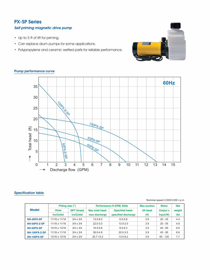
• Up to 5 ft of lift for priming.
• Can replace drum pumps for some applications.
• Polypropylene and ceramic wetted parts for reliable performance.
PX-SP SeriesSelf priming magnetic drive pump
Specification table
Pump performance curve
Fitting size (") Performance ft-GPM, 60HzModel
Nominal speed 2,500/3,000 r.p.m
NH-40PX-SPNH-50PX-Z-SPNH-50PX-SPNH-100PX-Z-SPNH-100PX-SP
HoseInxOutlet
11/16 x 11/16
11/16 x 11/16
13/16 x 13/16
11/16 x 11/16
13/16 x 13/16
NPT threadInxOutlet3/4 x 3/4
3/4 x 3/4
3/4 x 3/4
3/4 x 3/4
3/4 x 3/4
Max total head-max discharge
13.5-8.0
22.0-3.0
16.5-9.8
36.0-4.8
20.7-13.2
Specified head-specified discharge
6.5-5.8
13.0-2.0
8.0-6.3
20.0-3.5
13.0-8.2
MotorOutput xInput(W)20 - 45
20 - 55
45 - 90
45 - 95
65 - 120
3.9
3.9
3.9
3.9
3.9
(ft)
Max suctionlift head
Net
(lb)weight
4.4
4.8
6.6
6.6
7.7

0
Tota
l hea
d (f
t)
Discharge flow (GPM)
60Hz
20
1
40 8060 120100 140 160 180 220200 240 260 280 300
2
3
4
8
5
7
6
9
10
150PS-SP
200PS-Z-SP
200PS-SP
250PS-SP
• Up to 7 ft of lift for priming.
• Polypropylene and ceramic wetted parts for reliable performance.
• Can replace drum pumps for some applications.
PS-SP SeriesSelf priming magnetic drive pump
Pump performance curve
Specification table
Fitting size(") Performance ft-GPM, 60HzModel
Nominal speed 2,500/3,000 r.p.m
NH-150PS-SPNH-200PS-Z-SPNH-200PS-SPNH-250PS-SP
HoseInxOutlet
1x1
1x1
1x1
1x1
NPT threadInxOutlet
1x1
1x1
1x1
1x1
Max total head-max discharge
27.0-18.5
52.5-10.0
39.0-29.0
46.0-31.7
Specified head-specified discharge
13.0-12.0
26.0-8.0
24.5-18.5
29.5-21.0
(ft)
Max suctionlift head
7.2
7.2
7.2
7.2
MotorOutput xInput(W)90-170
150-290
150-290
250-390
Net
(lb)weight
13
18
18
18

0
Tota
l hea
d (f
t)
Discharge flow (GPM)
60Hz
10
40-120PG40-100PG
40-140PG
40-160PG
20 30 40 50 60 70 80 13090 100 110 120 150140
20
40
80
60
140
120
100
160
180
220
200
32-100PG
32-120PG
32-140PG
32-160PG
32-180PG
• Applications include pharmaceutical, petrochemical, and
solvent processing.
• Standard NEMA motors and ANSI flanges.
• Wetted end uses SUS-316 and Sic materials.
PG SeriesRugged stainless steel and Sic construction
Specification table Allowable S.G. and required motor output
NH-32-100PGNH-32-120PGNH-32-140PGNH-32-160PGNH-32-180PGNH-40-100PGNH-40-120PGNH-40-140PGNH-40-160PG
75.HP
7.5HP
10HP
15HP
15HP
7.5HP
10HP
15HP
15HP
S.G:1.0 S.G:1.2
7.5HP
10HP
15HP
15HP
*20HP
10HP
15HP
15HP
15HP
10HP
15HP
15HP
15HP
*20HP
10HP
15HP
15HP
*20HP
S.G:1.5 S.G:1.9
15HP
15HP
15HP
*20HP
---
15HP
15HP
*20HP
---
Model
NH-32-100PGNH-32-120PGNH-32-140PGNH-32-160PGNH-32-180PGNH-40-100PGNH-40-120PGNH-40-140PGNH-40-160PG
Fitting size (")Outlet x Inlet
1 1/4 x 2
1 1/4 x 2
1 1/4 x 2
1 1/4 x 2
1 1/4 x 2
1 1/4 x 2
1/21
1/4 x 2 1/2
1 1/4 x 2
1/21
1/4 x 2 1/2
Duty pointft at GPM
49.2 at 56.8
65.6 at 56.8
88.6 at 56.8
141.0 at 56.8
164.0 at 56.8
49.2 at 113.6
62.3 at 113.6
88.6 at 113.6
137.8 at 113.6
Max pointft-GPM
62.3-79.3
85.3-79.3
115.0-79.3
151.0-79.3
190.0-79.3
59.0-145.3
82.0-145.3
115.0-145.3
154.2-145.3
Power requirement at duty point (HP)
5.6
7.5
9.7
12.5
15
6.3
8.7
11.3
13.5
Net weight
(lb)187
198
209
209
211
220
231
231
231
60Hz
Model
60Hz
Pump performance curve
Note:Pump mode with * mark requires trimming impeller diameter according to specific gravity, viscosity and applicable motor. --- means that operation is not available.

4013
4012~4026PH
0 10
3012~3026PH2
3012
3013
5012~5024PHNPSHr
4012
Discharge flow (GPM)
5013
5012
3024
3026
Tota
l hea
d (ft
)
Nominal speed : 3440 r.p.m
4026
4024
H-Q
5024
4
6
8
10
12
14
16
18
20
20 4030 7050 60 80 16011090 100 120 130 140 150 180170 200190 210
6
0
3
12
45
3024
30123013
3026
9
78
10
5012
4012
4013
50244026
4024
Pr
5013
Pow
er re
quire
men
t (H
P)
Discharge flow (GPM)10 4020 30 50 60 1601109070 80 100 140120 130 150 210190170 180 200
Nominal speed : 3440 r.p.m
Note:Pump mode with * mark requires trimming impeller diameter according to specific gravity, viscosity and applicable motor. --- means that operation is not available.
• Use glass fiber reinforced PPS (Ryton) for strength.
• One and two stage constructions.
• Pressure capability over 200 feet.
• Temperatures up to 190 F.
PH SeriesHigh pressure magnetic drive pump
Pump performance curve
Model identification
N H - 3 0 1 2 P H - C V - G(4) (3) (2) (1)
ModelSeries
Pipe connection : G BS thread N NPT threadCombination of abrasion partsCV : Carbon bearing *Ceramic spindle *FKM O ringSi : Sic bearing *Ceramic spindle *FKM O-ring
Specification table
Model
NH-3012PHNH-3013PHNH-3024PHNH-3026PHNH-4012PHNH-4013PHNH-4024PHNH-4026PHNH-5012PHNH-5013PHNH-5024PH
1 x 1 1/2
Fitting size (") Pump performanceSpecific point ft at GPM
65.5 at 26.598.5 at 26.5
131.0 at 26.5196.5 at 26.565.5 at 58.098.5 at 58.0
131.0 at 58.0196.5 at 58.065.5 at 119.098.5 at 119.0
131.0 at 119.0
Max point ft-GPM S.G 1.0 S.G 1.3 S.G 1.5
85.0-47.5118.0-47.5167.0-47.5230.0-47.582.0-95.0
111.5-95.0161.0-95.0223.0-95.079.0-142.5
108.0-142.5157.5-142.5
Motor HPat GPM
discharge flow
At 26.5GPM
Application motor HP
235535
7.5105
7.510
235
7.55
7.510157.51015
35
7.57.57.5101515101515
Outlet x Inlet60Hz 60Hz
1 1/2 x 2
2 x 2 1/2
At 58.0GPM
At 119.0GPM
NEWProduct