Compact Controller for Stand-by and Parallel Operating Gen … guide.pdf · InteliGenNT,...
26
Copyright © 2005 ComAp s.r.o. ComAp, spol. s r.o. Světova 7, 180 00 Praha 8, Czech Republic Tel: +420 266 790 611, Fax: +420 266 316 647 E-mail: [email protected] , www.comap.cz OPERATOR GUIDE Compact Controller for Stand-by and Parallel Operating Gen-sets InteliGen NT , InteliSys NT Modular Gen-set Controller Operator guide for SPI, SPtM, MINT, COX IG-NT, IG-NTC, IG-EE, IG-EEC, IS-NT Software version IGS-NT-2.0, September 2006
Transcript of Compact Controller for Stand-by and Parallel Operating Gen … guide.pdf · InteliGenNT,...

Copyright © 2005 ComAp s.r.o.
ComAp, spol. s r.o. Světova 7, 180 00 Praha 8, Czech Republic
Tel: +420 266 790 611, Fax: +420 266 316 647E-mail: [email protected], www.comap.cz
OPERATOR GUIDE
Compact Controller for Stand-by and Parallel Operating Gen-sets
InteliGenNT, InteliSysNT
Modular Gen-set Controller
Operator guide for SPI, SPtM, MINT, COX
IG-NT, IG-NTC, IG-EE, IG-EEC, IS-NT
Software version IGS-NT-2.0, September 2006

InteliGenNT, InteliSysNT – Operator guide, SW version 2.0, ©ComAp – September 2006 2 IGS-NT-2.0-Operator guide.pdf
Table of Contents Table of Contents .................................................................................................................................... 2 General guidelines................................................................................................................................... 3
Description of the controller system.................................................................................................... 3 Available documentation ......................................................................................................................... 4
Inteli NT general manuals ................................................................................................................... 4 Inteli NT application manuals .............................................................................................................. 4 Inteli NT PC tools manuals.................................................................................................................. 5 Inteli common manuals ....................................................................................................................... 5 Conformity declaration ........................................................................................................................ 6 !! Warnings !! ....................................................................................................................................... 6
Operator interface.................................................................................................................................... 7 InteliGenNT pushbuttons and LEDs ..................................................................................................... 7 InteliSysNT pushbuttons and LEDs...................................................................................................... 9 Description of InteliGenNT MEASUREMENT screens....................................................................... 14 Description of InteliSysNT MEASUREMENT screens........................................................................ 16 Users and Passwords ....................................................................................................................... 22
Mode and function description .............................................................................................................. 23 OFF mode ......................................................................................................................................... 23 MAN mode ........................................................................................................................................ 23 AUT mode ......................................................................................................................................... 23 TEST mode (SPtM only) ................................................................................................................... 24 SEM mode......................................................................................................................................... 24
List of abbreviations............................................................................................................................... 25

InteliGenNT, InteliSysNT – Operator guide, SW version 2.0, ©ComAp – September 2006 3 IGS-NT-2.0-Operator guide.pdf
General guidelines This manual provides general information on how to operate the IG/IS-NT controller. This manual is intended for everybody who is concerned with operation and maintenance of the gen-set.
Description of the controller system NT family controllers are comprehensive AMF-controllers for single and multiple generating sets operating in stand-by or parallel modes. Synchronizer, isochronous load sharer, Mains and Generator protections allow for a total integrated solution for gen-sets in stand-by and parallel modes with multiple engine support. NT family controllers are equipped with a powerful graphic display showing icons, symbols and bar-graphs for intuitive operation, which sets, together with high functionality, new standards in gen-set controls. The controller automatically starts the gen-set, closes the gen-set C.B. when all conditions are met, then stops the engine on external signal or by pressing push buttons. Parallel to Mains operation can be achieved without additional HW. Forward and reverse synchronizing, Mains protection including vector shift, load and power factor control, earth fault protection are the major functions provided. Interfacing to foreign synchronizers and load sharers is supported. The key feature of NT family controllers is their easy-to-use installation and operation. Predefined configurations for typical applications are available as well as user-defined configurations for special applications.
Default applications There are four default applications: SPI, SPtM, MINT, COX. SPI Single Parallel Island application - for single gen-sets in parallel with mains or in island
operation; suitable for CHP application; no MCB control SPtM Single Parallel to Mains application - for single gen-sets in parallel with mains or in island
operation, with AMF support; both MCB and GCB controlled MINT Multiple application with INTernal control loops - for multiple gen-sets in island parallel or
mains parallel operation; Load Sharing and VAr Sharing controlled internally; PMS available
COX A special application intended for COoperation with an eXternal supervisory control system, e.g. PLC. Most internal control sequencies are removed or reduced, all major actions (synchronizing, load control type) are initiated via binary inputs to the NT controller.
Hint: Text with cyan background is valid for InteliSysNT only!

InteliGenNT, InteliSysNT – Operator guide, SW version 2.0, ©ComAp – September 2006 4 IGS-NT-2.0-Operator guide.pdf
Available documentation
Inteli NT general manuals
IGS-NT-2.0-Application guide.pdf Dedicated to gen-set control panel builders and project designers. Covers above all following items:
• IG/IS-NT hardware options • Comparison of number of I/O and communication ports in different HW modifications • Order codes overview • Applications overview – purpose, connection recommendations, function description • PLC functions description • Virtual peripherals – principle and usage
IGS-NT-2.0-Installation guide.pdf Dedicated to gen-set control panel builders and everybody concerned with installation of the gen-set. Includes information about following topics:
• Terminals and dimensions of all controllers and peripheral modules • Recommended wirings • Controllers’ interface options • Default sensors • Speed governor interfaces • AVR interfaces • Technical data
IGS-NT-2.0-Operator guide.pdf Dedicated to everybody concerned with operation and maintenance of the gen-set. It describes
• Operator interface • Measurement screens of the NT family controllers • Modes and function of the controller. • IG/IS-NT Available documentation list
IGS-NT-2.0-Troubleshooting guide.pdf Includes description of possible troubles during configuration, adjustment and operation of the controller. Consists of two parts:
• List of troubles and their solution • How to … section with recommended procedures in some typical situations
Inteli NT application manuals For each application an appropriate manual is available:
IGS-NT-SPTM-2.0.pdf
IGS-NT-SPI-2.0.pdf
IGS-NT-MINT-2.0.pdf
IGS-NT-COX-2.0.pdf
InteliGenNT, InteliSysNT – Operator guide, SW version 2.0, ©ComAp – September 2006 5 IGS-NT-2.0-Operator guide.pdf
They include these sections: • Modes description (OFF, MAN, AUT, …) • Functions description (e.g. Load shedding, Power management, Start/Stop sequences) • Protections and alarm management • Gen-set operation states • Inputs and outputs • Setpoints • List of abbreviations
Inteli NT PC tools manuals
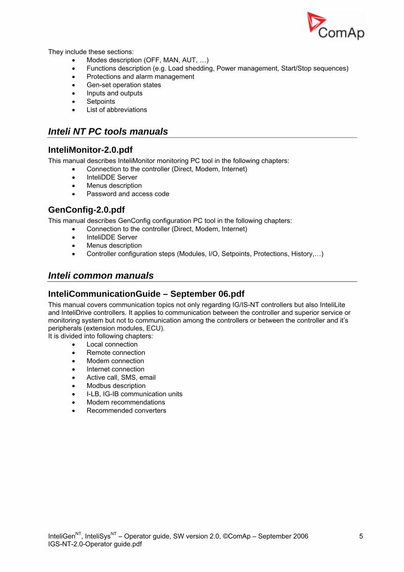
InteliMonitor-2.0.pdf This manual describes InteliMonitor monitoring PC tool in the following chapters:
• Connection to the controller (Direct, Modem, Internet) • InteliDDE Server • Menus description • Password and access code
GenConfig-2.0.pdf This manual describes GenConfig configuration PC tool in the following chapters:
• Connection to the controller (Direct, Modem, Internet) • InteliDDE Server • Menus description • Controller configuration steps (Modules, I/O, Setpoints, Protections, History,…)
Inteli common manuals
InteliCommunicationGuide – September 06.pdf This manual covers communication topics not only regarding IG/IS-NT controllers but also InteliLite and InteliDrive controllers. It applies to communication between the controller and superior service or monitoring system but not to communication among the controllers or between the controller and it’s peripherals (extension modules, ECU). It is divided into following chapters:
• Local connection • Remote connection • Modem connection • Internet connection • Active call, SMS, email • Modbus description • I-LB, IG-IB communication units • Modem recommendations • Recommended converters

InteliGenNT, InteliSysNT – Operator gIGS-NT-2.0-Operator guide.pdf
Conformity declaration
Following described machine complies with the appropriate basic safety and health requirement of the EC Low Voltage Directive No: 73/23 / EEC and EC Electromagnetic Compatibility Directive 89/336 / EEC based on its design and type, as brought into circulation by us.
!! Warnings !!
Be aware that the binary outputs can change state during and after software reprogramming (before the controller is used again ensure that the proper
configuration and setpoint settings are set in the controller)!!!
Be aware that gen-set can automatically or remotely start when following controller terminals are disconnected !!!
• Mains voltage measuring and / or • Binary outputs for MCB control and / or • MCB feedback
Switch InteliGenNT to OFF mode and disconnect the Binary outputs Starter and Fuel to
avoid unexpected automatic start of gen-set and GCB closing.
Note: ComAp believes that all informationupdate at any time. ComAp does nundertaken.
Dangerous voltage In no case touch the terminals for Always properly connect groundin Take care when disconnecting In/IFor safety connect parallel to cont In any case do not disconnect gen
Adjust set points All setpoints are preadjusted to thesettings group !!must!! be adjuste
!!! WRONGC
The followi
To avoid personal injury d
!!! CAUTION !!!
voltage and current measurement! g terminals!
m3 terminals when the gen-set is stopped. roller In/Im3 terminals two anti parallel diodes 10A/100V.
erator CT terminals when the gen-set is loaded.
ir typical values. But the setpoints in the “Basic settings” d before the first startup of the gen-set. ADJUSTMENT OF BASIC PARAMETERS AN DESTROY THE GEN-SET !!!
ng instructions are for qualified personnel only. o not perform any action not specified in this User guide !!!
uide, SW version 2.0, ©ComAp – September 2006 6
provided herein is correct and reliable and reserves the right to ot assume any responsibility for its use unless otherwise expressly

InteliGenNT, InteliSysNT – Operator guide, SW version 2.0, ©ComAp – September 2006 7 IGS-NT-2.0-Operator guide.pdf
Operator interface
InteliGenNT pushbuttons and LEDs
Pushbuttons: 1. MODE→ Cycle forward through gen-set operation modes OFF MAN AUT TEST. 2. ←MODE Cycle backward through gen-set operation modes OFF MAN AUT TEST. 3. HORN RESET Deactivates the HORN (AUDIBLE ALARM). 4. FAULT RESET Acknowledges faults and alarms. 5. START Starts the gen-set in MAN mode. 6. STOP Stops the gen-set in MAN mode. 7. MCB ON/OFF Opens and closes (synchronizes) the Mains circuit breaker in MAN
mode. 8. GCB ON/OFF Opens and closes (synchronizes) the Generator circuit breaker in
MAN mode. 9. ESC
Where Function Measurement screens, Alarm list
Go to Menu screen
Setpoints screen Go to Menu screen; within setpoint group, go to group list
Setpoint edit Leave setpoint edit without changes History screen Go to Menu screen FastEdit screen Fast edit exit (to previous measurement screen)
without changes Language screen Language screen exit (to menu) without save
10
11
9
13
12 16 7 15 20
8
14
17
3
6
5
21
19
18
2 1 4

InteliGenNT, InteliSysNT – Operator guide, SW version 2.0, ©ComAp – September 2006 8 IGS-NT-2.0-Operator guide.pdf
10. ↑ Select the setpoint, select the screen, select history record or increase setpoint value.
11. ↓ Select the setpoint, select the screen, select history record or decrease setpoint value.
12. → Moves history record displayed columns to the right, 5% increase of edited setpoint’s value (step given by the setpoint range), go back from Alarm list.
13. ← Moves history record displayed columns to the left, 5% decrease of edited setpoint’s value (step given by the setpoint range), view Alarm list from measurement screens.
14. ENTER
Pushbuttons’ combinations Following table determines controller functions when ↑, ↓, ←, →, ENTER and PAGE buttons’ combination is pressed: Where Pushbutton combination Function Measurement screens, Alarm list
ENTER + ↑ ENTER + ↓ ENTER + ESC
Contrast increase Contrast decrease Info screen
Info screen ENTER + ↑ ENTER + ↓
Backlight increase Backlight decrease
LEDs
15. MAINS VOLTAGE PRESENT: GREEN LED is on, if voltage on the mains terminals is present (in SPI and SPtM). LED is not active in MINT, COX.
16. MAINS FAILURE: RED LED starts flashing when the mains failure occurs and gen-set does not run, goes to steady light when the gen-set starts and goes off when the mains restores. 17. GEN VOLTAGE PRESENT: GREEN LED is on, if gen. voltage is present and within limits. 18. GEN-SET FAILURE: RED LED starts flashing when any failure occurs. After FAULT RESET button is pressed, goes to steady light (if an alarm is still active) or is off (if no alarm is active). 19. GCB ON: GREEN LED is on, if GCB feedback is active. Flashes during synchronizing. 20. MCB ON: GREEN LED is on, if MCB feedback is active. Flashes during reverse synchronizing (synchronizing of the loaded gen-set back to the restored mains). 21. Bus – GREEN LED is on if bus voltage is present and within limits.
Where Function Menu screen Go to selected display group (Measurement CU,
Measurement IO, …) Measurement screens, Alarm list
Go to FastEdit screen (hold ENTER for 4 sec.) – then it is possible to adjust selected setpoint (typically Base load for standard SPtM)
Setpoints screen Go to selected setpoint group Setpoint edit Start setpoint edit / save changes History screen Go to the first column of the first history record FastEdit screen FastEdit exit (to previous measurement screen)
with setpoint change Language screen Language screen exit (to menu) and save
selection

InteliGenNT, InteliSysNT – Operator guide, SW version 2.0, ©ComAp – September 2006 9 IGS-NT-2.0-Operator guide.pdf
InteliSysNT pushbuttons and LEDs
Pushbuttons: 1. Numeric keypad
Where Function Setpoints screen Change setpoint value Menu screen Go to selected display group directly Measurement screens Go to another screen directly Language screen Select language directly History screen If pressed ± button a symbol appears on the
display (bottom right corner) and it is possible to move by one page of records using arrow buttons
2. Clear Clears character on the left side of the cursor, exits from menu 3. Enter
Where Function Menu screen Go to selected display group (Measurement CU,
Measurement IO, …) Measurement screens, Alarm list
Go to FastEdit screen (hold ENTER for 4 sec.) – then it is possible to adjust selected setpoint (typically Base load for standard SPtM)
Setpoints screen Go to selected setpoint group Setpoint edit Start setpoint edit / save changes History screen Go to the first column of the first history record FastEdit screen FastEdit exit (to previous measurement screen)
with setpoint change Language screen Language screen exit (to menu) and save
selection
1 2 3
4
5
6
7
8
9
24
23 10 22 11 21 20 15 14 16 19 18
12
13
17

InteliGenNT, InteliSysNT – Operator guide, SW version 2.0, ©ComAp – September 2006 10 IGS-NT-2.0-Operator guide.pdf
4. Mode→ Cycle forward through gen-set operation modes OFF MAN SEM AUT TEST. 5. ←Mode Cycle backward through gen-set operation modes OFF MAN SEM AUT TEST. 6. START Starts the gen-set in MAN or SEM mode. 7. STOP Stops the gen-set in MAN or SEM mode. 8. FAULT RESET Acknowledges faults and alarms. 9. HORN RESET Deactivates the horn (audible alarm). 10. MCB ON/OFF Opens and closes (synchronizes) the Mains circuit breaker in MAN mode
(SPtM application only). 11. GCB ON/OFF Opens and closes (synchronizes) the Generator circuit breaker in MAN mode. 12. ESC
Where Function Measurement screens, Alarm list
Go to Menu screen
Setpoints screen Go to Menu screen; within setpoint group, go to group list
Setpoint edit Leave setpoint edit without changes History screen Go to Menu screen FastEdit screen Fast edit exit (to previous measurement screen)
without changes Language screen Language screen exit (to menu) without save Table of characters Jump among table of characters, menu and text
line
13. ↑ Select the setpoint, setpoint group, select the screen, select history record, increase setpoint value, edit stringlist value, select language
14. ↓ Select the setpoint, setpoint group, select the screen, select history record, decrease setpoint value, edit stringlist value, select language
15. → In AlarmList screen, shift the Alarm list page down (if more than 7 items), moves history record displayed columns to the right
16. ← In AlarmList screen, shift the Alarm list page up (if more than 7 items), moves history record displayed columns to the left, go to Info screen
17. Enter Same as 3. 18. Alarm list Shortcut to Alarm list screen from any other screen 19. History Shortcut to History screen from any other screen
Pushbuttons’ combinations Following table determines controller functions when ↑, ↓, ←, →, ENTER and PAGE buttons’ combination is pressed: Where Pushbutton combination Function Measurement screens, Alarm list
ENTER + ↑ ENTER + ↓ ENTER + ESC
Contrast increase Contrast decrease Info screen
Info screen ENTER + ↑ ENTER + ↓
Backlight increase Backlight decrease
History screen number + ENTER Go to record with this number
LEDs: 20. Mains status LED 21. MCB status LED 22. Load status LED 23. GCB status LED 24. Gen-set status LED

InteliGenNT, InteliSysNT – Operator guide, SW version 2.0, ©ComAp – September 2006 11 IGS-NT-2.0-Operator guide.pdf
How to select gen-set mode? Use MODE→ or ←MODE to select requested gen-set operation mode OFF – MAN – SEM – AUT – TEST. It is not possible to go directly from OFF to AUT or TEST.
Display menus There are several display menus (functions) available: ALARMLIST, MEASUREMENT CU, MEASUREMENT IO, SETPOINTS, HISTORY, PASSWORD and LANGUAGE. Each menu consists of several screens. Pressing the ESC (repeatedly when necessary) button the menu screen will be displayed. Hint: IS-NT – When pressing ESC on the screen with characters, focus jumps from menu to bottom line and table of characters. See picture on the right.
How to view Alarm list? 1. Select the ALARMLIST menu item and press ENTER or press ← in measurements’ screens
to go directly to the Alarm list.
How to view measured data? 1. Select the MEASUREMENT CU menu item and press ENTER. 2. Use ↑ and ↓ to select the screen with requested data.
How to view IO values? 1. Select the MEASUREMENT IO menu item and press ENTER. 2. Use ↑ and ↓ to select the screen with requested data.
How to view and edit setpoints? 1. Select SETPOINTS menu item and press ENTER. 2. Use ↑ or ↓ to select requested set points group. 3. Press ENTER to confirm. 4. Use ↑ or ↓ to select requested set point. 5. Set points marked are password protected. 6. Press ENTER to edit. 7. Use ↑ or ↓ to modify the set point. When ↑ or ↓ is pressed for 2 sec, auto repeat function
and speedup is activated. Use ← or → to change the setpoint value by 5% of it’s range. 8. Press ENTER to confirm or ESC to leave without change. 9. Press ESC to leave selected set points group.
How to view the HISTORY menu? 1. Select HISTORY menu item and press ENTER 2. Use ↑ or ↓ to select a requested record. 3. Use → or ← to cycle forward/backward through columns of the record. 4. Press ± to cycle through the whole screens of columns/rows.
How to change password? 1. Select USERS/PASSWORD menu item and press ENTER. 2. Use ↑ or ↓ to select User. 3. Press ENTER to confirm.

InteliGenNT, InteliSysNT – Operator guide, SW version 2.0, ©ComAp – September 2006 12 IGS-NT-2.0-Operator guide.pdf
4. Select ChangePassword and press ENTER 5. Use ↑ or ↓ or ← or → to set new password 6. Press ENTER to confirm password
How to set Language? 1. Select LANGUAGE menu item (if not already selected) and press ENTER 2. Use ↑ or ↓ to select a requested Language. 3. Press ENTER to confirm.
Hint: If binary inputs Lang sel int A,B,C (for IG-NT/EE internal display and IS-Display with address 1) or Lang sel #2 A,B,C (for IG-Display and IS-Display with address 2) or Lang sel #3 A,B,C (for IS-Display with address 3) are used, it is not possible to change languages from Language screen.
Language 0 1 2 3 4 5 6 7 Lang sel xxx A 0 1 0 1 0 1 0 1 Lang sel xxx B 0 0 1 1 0 0 1 1 Lang sel xxx C 0 0 0 0 1 1 1 1
How to change the display contrast? Press and hold ENTER and use ↑ or ↓ to adjust the best display contrast. Hint: Available from the MEASUREMENT screens only.
How to check the serial number and software revision? Hold down the ENTER and then press ESC. On the display you can see controller INFO screen for 10 seconds.
InteliGenNT InteliSysNT Controller INFO screen contains:
1. Controller name (see Basic settings group)
2. Controller serial number (8 character number), SW version, ID string and release date
3. Application: SPtM, SPI, COX… Using → you can view the INFO2 screen which contains:
1. Display SW version 2. ID chip and Dongle content 3. Password decoding string
Controller INFO screen contains: 1. Controller name (see Basic settings group) 2. Firmware and release date 3. Controller serial number (8 character
number) 4. Application: SPtM, SPI, COX… 5. Password decode number 6. IS-Display version and release date 7. Encoding: available character sets
Using → you can view the INFO2 screen which contains: 1. IDch: ID string 2. Dngl: connected dongle 3. Supported code pages
Using → again you can view the INFO3 screen which contains: 1. IS-Display IDchip: ID string
Hint: Available from the MEASUREMENT screens only.
How to view Connection screen on IG-Display? Press ↑ button when in Info screen to see information about IG-Display hardware version and properties and actual state of communication with the master controller.
How to change the display backlight intensity? Hold down the ENTER and then press ESC. On the display you can see Controller INFO screen for 10 seconds. Press and hold ENTER when in INFO screen and use ↑ or ↓ to adjust the best display backlight.

InteliGenNT, InteliSysNT – Operator guide, SW version 2.0, ©ComAp – September 2006 13 IGS-NT-2.0-Operator guide.pdf
Backlight intensity is set for one of the two modes, depending on the activity of configurable binary input Alt brightness (IG-NT/EE and modifications). For IG-Display and IS-Display modules, this binary input is located in the Power connector and it’s function is fixed (not configurable). IS-Display with address 1 reads analog input LCD brightness on IS-NT-BB and changes accordingly display backlight intensity in the range 0-100%. Hint: Backlight intensity change available from the MEASUREMENT screens only.
How to find active alarms? Select Alarmlist menu item and press ENTER or press ← in MEASUREMENT IO or MEASUREMENT CU menu. Inverted alarms are still active. Non-inverted alarms are not active, but not yet confirmed. Press FAULT RESET to accept all alarms (an asterix mark disappears when an alarm is accepted by FAULT RESET). Non-active alarms immediately disappear from the list. Active alarm list appears on the screen automatically when a new alarm comes up and Main MEASUREMENT screen was selected. Hint: Alarm list does not activate automatically if the display is switched to any other screen than the first one of MEASUREMENT (typically the screen that shows menu selector on the upper). The automatic jump to the alarm list screen will not occur if you are listing through the measured values, set points or history! If setpoint Engine protect:ResetActAlarms is set to DISABLED, only inactive alarms can be reset. If an active alarm is present in the alarm list, controller display blinks every 30 seconds.
When to use GCB ON/OFF button? The button is disabled in AUT mode. In MAN and TEST modes it is enabled, but before closing of the circuit beaker, generator voltage and frequency must be within limits. The controller has internal protection to avoid the breaker closure without synchronizing. The controller recognizes automatically:
• if there is mains / bus voltage and the gen-set shall be synchronized before closing the GCB • or if there is no voltage on the bus and the GCB can be closed without synchronizing.
When to use MCB ON/OFF button? The button is disabled in AUT mode. Use this button in MAN or TEST mode to close or open the MCB. Be careful while doing this, because you can disconnect the load from the mains!!!

InteliGenNT, InteliSysNT – Operator guide, SW version 2.0, ©ComAp – September 2006 14 IGS-NT-2.0-Operator guide.pdf
Description of InteliGenNT MEASUREMENT screens
Main measure screen
1 2
6
3
4
7
5
8
OFF MAN AUT TEST
ReadyMains OperPF 0.00RPM 0Timer 0
R
9
1. Operation mode of the gen-set 2. Indication of active alarm 3. Status of the gen-set 4. Actual electric condition 5. RPM of the gen-set 6. Active power 7. Power factor 8. Timer – event’s counting time (e.g. prestart, cooling, …) 9. Signalizes, when any remote connection to controller is active
Following table contains an example of MINT and SPtM MEASUREMENT screens. Other applications can be slightly different.
Measurement CU

InteliGenNT, InteliSysNT – Operator guide, SW version 2.0, ©ComAp – September 2006 15 IGS-NT-2.0-Operator guide.pdf
MINT SPtM Total power screen
30kW0.90C
-20kW1.00R
PWR I/E -20 10kW
0.90L
Left up corner: Actual power control mode None or Base or Imp/Exp and required power values. Load: Actual value of active power. Actual value of PF Mains: Actual value of active power. Actual value of PF Gen-set: Actual value of active power. Actual value of PF
Generator (frequency, voltage) Gen freq Gen V1, V2, V3 ph-N (triple bargraph) Gen V12, V23, V31 ph-ph (triple bargraph)
Generator (frequency, voltage) Gen freq Gen V1, V2, V3 ph-N (triple bargraph) Gen V12, V23, V31 ph-ph(triple bargraph)
Generator (current) Gen I1, I2, I3 (triple bargraph)
Generator (current) Gen I1, I2, I3 (triple bargraph)
Bus (frequency, voltage) Bus freq Bus V1, V2, V3 ph-N (triple bargraph) Bus V12, V23, V31 ph-ph (triple bargraph)
Mains (frequency, voltage) Mains freq Mains V1, V2, V3 ph-N (triple bargraph) Mains V12, V23, V31 ph-ph (triple bargraph)
Bus (current) Im3/EarthFC (single bargraph)
Mains (current, power, PF) Im3/EarthFC (single bargraph) P mains Q mains Mains PF MaxVectorS
Gen-set power Active power (total and per phase) Power factor (total and per phase) Reactive power kVAr (total and per phase) Apparent power (total and per phase)
Gen-set power Active power (total and per phase) Power factor (total and per phase) Reactive power kVAr (total and per phase) Apparent power (total and per phase)
IG-CU Analog inputs Battery voltage (single barograph) CPU temp (single barograph) Dplus (single barograph)
IG-CU Analog inputs Battery voltage (single barograph) CPU temp (single barograph) Dplus (single barograph)
Synchroscope Slip frequency Synchroscope V1g Generator first phase voltage V1b Bus first phase voltage SRO Speed regulator output indication in the range 0 to ±10,00V VRO Voltage regulator output indication in the range 0 to 100%.
Synchroscope Slip frequency Synchroscope V1g Generator first phase voltage V1m Mains first phase voltage SRO Speed regulator output indication in the range 0 to ±10,00V VRO Voltage regulator output indication in the range 0 to 100%.

InteliGenNT, InteliSysNT – Operator guide, SW version 2.0, ©ComAp – September 2006 16 IGS-NT-2.0-Operator guide.pdf
Measurement IO
IG-CU analog inputs AI1 to AI3
IG-CU analog inputs AI1 to AI3
+ inputs/outputs of connected ECU and/or modules, depending on actual configuration.
Description of InteliSysNT MEASUREMENT screens
Main menu screen
1. Selection of alarm list, measurement, history, setpoints, languages or user screen. 2. Cursor shows actual selection. 3. Controller mode indication. Black background indicates active mode (MAN mode in the
above example). 4. Timer – events counting time (e.g. prestart, cooling). 5. Engine machine state indication. 6. Electric machine state indication. 7. Actual gen-set power (requested gen-set power).
Statistic Run hours Number of starts Number of unsuccessful starts Service time 1 Service time 2 Service time 3 Service time 4
Statistic Run hours Number of starts Number of unsuccessful starts Service time 1 Service time 2 Service time 3 Service time 4
Statistic kWhours kVArhours Time Date
Statistic kWhours kVArhours Time Date
Power management Engine priority Total running actual power Actual reserve (single barograph) CAN16 CAN32
2
1
3
4
5 6 7 8
9
10
InteliGenNT, InteliSysNT – Operator guide, SW version 2.0, ©ComAp – September 2006 17 IGS-NT-2.0-Operator guide.pdf
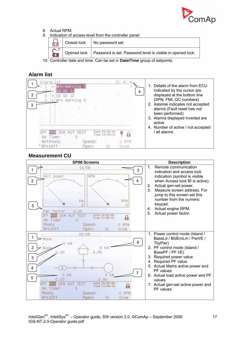
8. Actual RPM. 9. Indication of access level from the controller panel:
Closed lock No password set
Opened lock Password is set. Password level is visible in opened lock.
10. Controller date and time. Can be set in Date/Time group of setpoints.
Alarm list
1. Details of the alarm from ECU
indicated by the cursor are displayed at the bottom line (SPN, FMI, OC numbers)
2. Asterisk indicates not accepted alarms (Fault reset has not been performed)
3. Alarms displayed inverted are active
4. Number of active / not accepted / all alarms
Measurement CU SPtM Screens Description
1. Remote communication indication and access lock indication (symbol is visible when Access lock BI is active).
2. Actual gen-set power. 3. Measure screen address. For
jump to this screen set this number from the numeric keypad.
4. Actual engine RPM. 5. Actual power factor.
1. Power control mode (Island / BaseLd / BldEmLm / PwrI/E / TbyPwr)
2. PF control mode (Island / BasePF / PF I/E)
3. Required power value 4. Required PF value 5. Actual Mains active power and
PF values 6. Actual load active power and PF
values 7. Actual gen-set active power and
PF values
1
2
3
4
5
1
2
3
4
6
5 7
1
2 4
3
InteliGenNT, InteliSysNT – Operator guide, SW version 2.0, ©ComAp – September 2006 18 IGS-NT-2.0-Operator guide.pdf
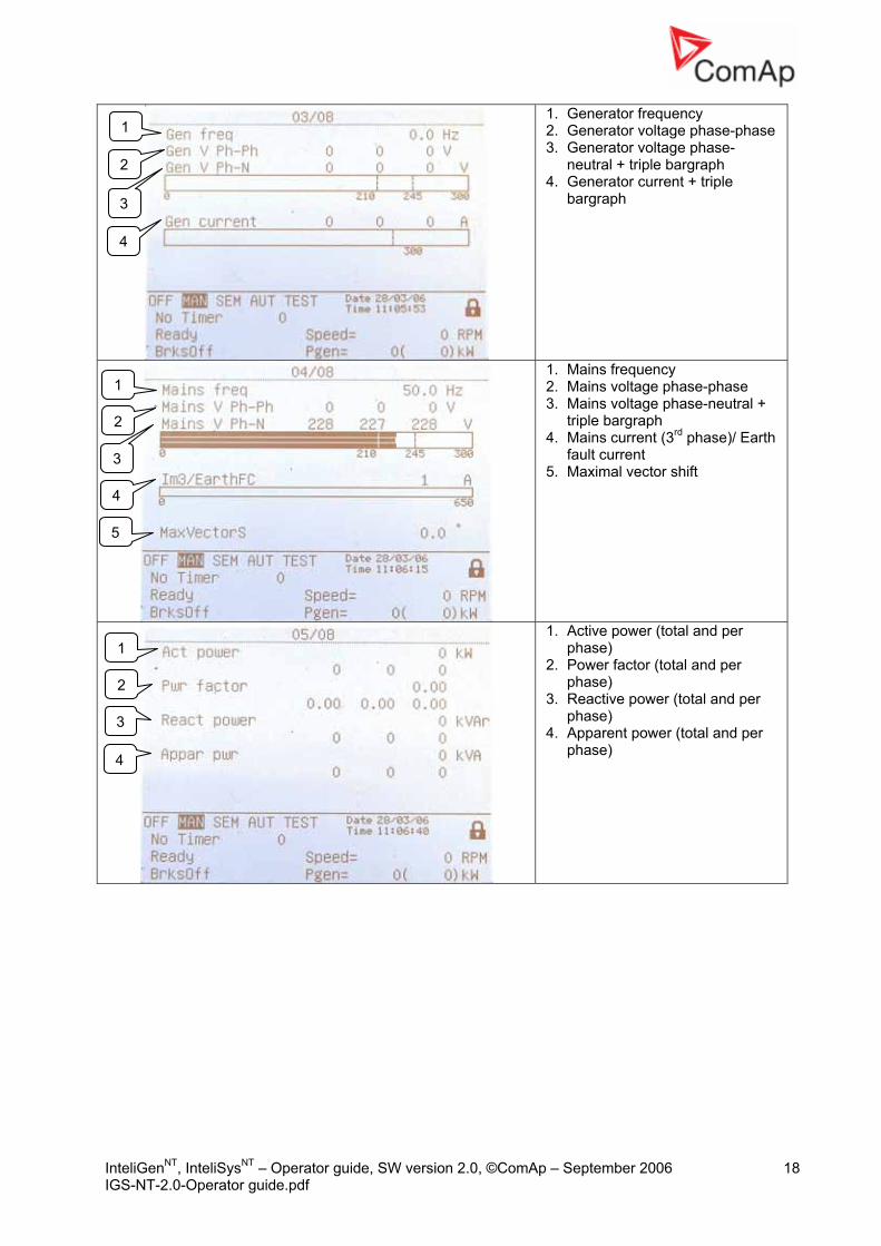
1. Generator frequency 2. Generator voltage phase-phase 3. Generator voltage phase-
neutral + triple bargraph 4. Generator current + triple
bargraph
1. Mains frequency 2. Mains voltage phase-phase 3. Mains voltage phase-neutral +
triple bargraph 4. Mains current (3rd phase)/ Earth
fault current 5. Maximal vector shift
1. Active power (total and per phase)
2. Power factor (total and per phase)
3. Reactive power (total and per phase)
4. Apparent power (total and per phase)
1
2
3
4
1
2
3
4
5
1
2
3
4

InteliGenNT, InteliSysNT – Operator guide, SW version 2.0, ©ComAp – September 2006 19 IGS-NT-2.0-Operator guide.pdf
1. Battery voltage 2. CPU temperature 3. D+ voltage
1. Synchroscope 2. Slip frequency 3. Actual angle between generator
and mains voltage 4. Generator first phase voltage 5. Mains first phase voltage 6. Voltage match of all three
phases (0 – doesn’t match; 1 – OK)
7. SRO – Speed Regulator Output indication in the range SpeedGovLowLim – SpeedGovHiLim
8. VRO – Voltage Regulator Output indication in the range 0 – 100%
Statistics 1. Total engine running hours 2. Total number of starts 3. Total number of unsuccessful
starts 4. Service times (set in Engine
protect group of setpoints) 5. Total gen-set kW hours 6. Total gen-set kVAr hours Note: Statistics can be set in InteliMonitor → Set statistics… after password of User 0 is entered.
1
2
3
1 2
3
4
5
6
7
8
1
2
3
4
5
6

InteliGenNT, InteliSysNT – Operator guide, SW version 2.0, ©ComAp – September 2006 20 IGS-NT-2.0-Operator guide.pdf
Measurement IO SPtM Screens Description
IS-NT analog inputs 1. Analog input 1 (e.g. Oil
pressure) 2. Analog input 2 (e.g. Primary
water temperature) 3. Analog input 3 (e.g. Fuel level) 4. analog input 4 (e.g. Secondary
water temperature)
IS-NT binary inputs indication
IS-NT binary outputs indication
1
2
4
3

InteliGenNT, InteliSysNT – Operator guide, SW version 2.0, ©ComAp – September 2006 21 IGS-NT-2.0-Operator guide.pdf
If the temperatures of cylinders are configured/measured it is possible to see bargraphs of these temperatures on the separate screen.
Another screen shows the differences of cylinder temperatures from the average temperature.
Further screens are automatically added if I/O extension modules or ECU are connected to the controller.
History
1. Bottom lines show record number, reason, date and time even if other columns are actually displayed
1

InteliGenNT, InteliSysNT – Operator guide, SW version 2.0, ©ComAp – September 2006 22 IGS-NT-2.0-Operator guide.pdf
Users/Password
This screen shows list of users. To enter or change password of selected user press Enter.
Users and Passwords Up to 8 users can be defined in the system. Every user has it’s own defined level of access rights. There are seven levels of password protection. User O – Administrator has always level 7. Hint: The lock mark appears before a set point name (on controller screen) if the setpoint is password protected. The lock mark is removed only when the password is set from controller’s front panel. The lock mark is still visible on controller screen even if the password is set from different terminal. Even though one level may have been set from the front panel, the affected set points are not accessible from InteliMonitor (direct or Modem) until this level is set in InteliMonitor (direct or Modem). Set point screen opened from front panel is automatically closed 15 minutes after the last key has been pressed. It is possible to protect remote Start, Stop, GCB and MCB commands from InteliMonitor. This seven level command protection can be configured in GenConfig.
EnterPassword Password is a five-digit number (0 - 65535). Only setpoints associated with the entered password level can be modified. Use ↑ or ↓ to select the desired password and then press ENTER. Use ← or → to move the value by 5% of the range.

InteliGenNT, InteliSysNT – Operator guideIGS-NT-2.0-Operator guide.pdf
Mode and function description There are four gen-set operation modes: OFF - MAN – AUT – TEST in SPtM application. There are three gen-set operation modes: OFF - MAN – AUT in SPI, COX and MINT application. To select the mode use MODE→ or ←MODE.
OFF mode • No start of the gen-set is possible. Outputs STARTER, GCB CLOSE/OPEN and FUEL
SOLENOID are not energized. • No reaction if buttons START,STOP,GCB ON/OFF are pressed. • MCB behavior depends on AMF settings: MCB opens on setpoint:
MAINSFAIL: When power-cut comes, MCB opens. After Mains returns, MCB closes with MCB close del. GEN RUNNING:When power-cut comes, MCB stays closed until the gen-set starts and produces voltage within limits.
MAN mode 1) To start the gen-set press START. 2) When the generator voltage is within limits (adjusted in the setpoints group Generator protections) GCB green LED on the front panel lights. 3) Press GCB ON/OFF to close the GCB. If the generator voltage is out of the limits, controller does not respond to the GCB ON/OFF .
a) If controller detects dead bus, immediately closes GCB OPEN/CLOSE output. b) If controller detects voltage on the bus, starts synchronizing.
4) To stop the engine press STOP a) controller unloads the gen-set, opens GCB CLOSE/OPEN. Unloading is active only when binary input MCB feedback is closed or other gen-set is connected to bus. In other case GCB CLOSE/OPEN opens immediately. b) Gen-set is cooled down and stopped.
Hint: Controller does not respond to external signals and/or conditions. The gen-set is fully in manual control; there is no automatic way to stop it (except protections). The gen-set stays running until STOP button is pressed. Controller does not take place in Power management in MINT application
AUT mode Gen-set is controlled based on external signals (Rem start/stop, Sys start/stop) or conditions (AMF, Peak shaving, Power management system, …). Hint: Engine does not stop, if other condition for automatic starts is active. Example: If peak stop condition occurs, but REMOTE START/STOP is active, engine stays running. Controller does not respond to GCB ON/OFF , MCB ON/OFF, STOP, START buttons and corresponding remote InteliMonitor or Modbus commands. Set Basic setting: FltRes GoToMAN = ENABLED to avoid automatic engine start when pressing FAULT RESET after Shut down or Slow stop alarm.
Engine can start automatically without w
!!!!! VERY IMPORTANT !!!!!!
, SW version 2.0, ©ComAp – September 2006 23
arning when pressing FAULT RESET after shut down alarm.

InteliGenNT, InteliSysNT – Operator guide, SW version 2.0, ©ComAp – September 2006 24 IGS-NT-2.0-Operator guide.pdf
TEST mode (SPtM only) Use TEST mode for Gen-set start test if the Mains is OK or to transfer the load to the gen-set when Mains fail is announced in advance. Hint: The controller does not respond to GCB ON/OFF , STOP, START in Ret from test = AUTO. Engine automatically starts, when TEST mode is selected. Engine can start automatically without warning when pressing FAULT RESET after shut down alarm.
SEM mode START – starts the gen-set.
• The controller closes GCB to dead bus. • If the Mains is within limits and MCB is closed, the controller starts synchronizing and closes
GCB when synchronizing conditions are met. Gen-set remains running in parallel. • If Mains failure is recognized during parallel operation the controller opens MCB. • After Mains recovers the controller synchronizes MCB and returns to parallel operation
STOP – unloads the gen-set, opens GCB, cools down the engine and stops. AMF function – If the Mains fails while the gen-set is not running, the controller automatically starts and closes GCB. Other automatic starts/stops (e.g. due to peak shaving, BI Rem start/stop activation) are not performed in SEM mode.
Baseload Process control: Load ctrl PtM = BASELOAD Gen-set power is kept at value given by Process control:Base load setpoint.
Internal Import export ProcessControl: Load ctrl PtM = IMP/EXP Process control: IE measurement = IM3 CT INPUT Gen-set power is controlled to keep the import load at the level given by setpoint Process control: Import load value. Controller measures Import/Export value via current transformers connected to In/Im3 terminal. The value of L3 is then multiplied by 3 to give an estimation of the actual Imp/Exp.

InteliGenNT, InteliSysNT – Operator guide, SW version 2.0, ©ComAp – September 2006 25 IGS-NT-2.0-Operator guide.pdf
List of abbreviations AMF Auto Mains Failure (controller starts automatically on mains failure) AI Analog Input AO Analog Output ATS Automatic Transfer Switch (switches the load to actually supplied bus (by mains or generators)) AVR Automatic Voltage Regulator BI Binary Input BO Binary Output BOC Breaker Open & Cool-down - protection type (see application manual for details) BTB Bus-Tie Breaker CAN1 CAN bus for extension modules connection (e.g. IGS-PTM, IS-BIN8/16, IS-AIN8, I-AOUT8, I-
CB, IGL-RA15) CAN2 CAN bus for intercontroller communication (in multiple applications) and monitoring (connection
of I-LB, IG-IB) COX Application for Complex Systems where actions are taken by a PLC and the controller only
follows the orders => needs an external driver (cox) ESF Engine Specific File FMI Failure Mode Identifier GC Graphical Characters - option for additional support of one "graphical" language GCB Generator Circuit Breaker CHP Combined Heat & Power - cogeneration application, usually with gas engine I-AOUT8 Extension module with 8 AO I-CB Communication Bridge - interfaces IS, IG/IS-NT, ID controllers and non-standard engine ECU IG-AVRi IG Automatic Voltage Regulator interface IG-EE InteliGen for Electronic Engines (HW optimized for connection to an engine equipped with
ECU) IG-EEC InteliGen EE controller with extended communication possibilities + switchable sensing ranges
of AC voltages and currents IG-IB IG Internet Bridge - for internet/ethernet communication IGL-RA15 Indication panel with LEDs signalizing state of 15 BO IG-NT InteliGen New Technology gen-set controller IG-NTC InteliGen NT controller with extended communication possibilities + switchable sensing ranges
of AC voltages and currents IGS-NT-LSM+PMS Dongle for IG-XX and IS-NT to enable Load Sharing control loops and PMS IGS-PTM Extension module with 8 BI/BO, 4 AI and 1 AO I-LB Local Bridge – for direct and modem monitoring and control of multiple gen-sets IM-NT InteliMains New Technology - Mains supervision controller; the same controller in a different
SW configuration can work as a bus-tie synchronizer I-RB Relay Board IS-AIN8 Extension module with 8 AI. IS-BIN8/16 Extension module with 8 BO and 16 BI. IS-NT InteliSys New technology gen-set controller IS-NT-BB InteliSys New Technology Basic Box (without display) KWP2000 Key Word Protocol of Scania S6 unit (for engine diagnostics) LS Load Sharing - analog load sharing line to interconnect the gen-sets on the site (for isolated
parallel or mains parallel of multiple gen-sets); IG/IS-NT controllers use digital Load Sharing via

InteliGenNT, InteliSysNT – Operator guide, SW version 2.0, ©ComAp – September 2006 26 IGS-NT-2.0-Operator guide.pdf
CAN2 bus LSM Load Sharing Module LT Option for Low Temperature modification (display equipped with heating foil) MCB Mains Circuit Breaker MGCB Master Generator Circuit Breaker (sometimes used with multiple gen-sets in island parallel or
mains parallel operation) MINT Multiple application with INTernal control loops - for multiple gen-sets in island parallel or mains
parallel operation; Load Sharing and VAr Sharing controlled internally; PMS available MP Mains protection NPU Mains protection relay (voltage, frequency, vector shift protections) OC Occurrence Count (number of fault occurrances transmitted in diagnostic frame from ECU) OfL Off load - protection type (see application manual for details) PGN Parameter Group Number (refer to SAE J1939-71) PMS Power Management System - ensures optimization of running gen-sets on the site with multiple
gen-sets; based on kW/kVA spinning reserve or on relative (%) load; no-master system ensures high reliability
SHAIN Shared (virtual) Analog INput module SHAOUT Shared (virtual) Analog OUTput module SHBIN SHared (virtual) Binary INput module SHBOUT SHared (virtual) Binary OUTput module SPI Single Parallel Island application - for single gen-sets in parallel with mains or in island
operation; suitable for CHP application; no MCB control SPM Single Prime Mover application - for single gen-sets without mains SPN Suspect Parameter Number (refer to SAE J1939-71) SPtM Single Parallel to Mains application - for single gen-sets in parallel with mains or in island
operation, with AMF support; both MCB and GCB controlled SSB Single Stand-By application - for single gen-sets with mains and break transfer gen-set to
mains VPIO Virtual periphery I/O module – internal “SW wires” linking binary outputs to inputs VS VAr Sharing - ensures VAr sharing between the gen-sets on the site via CAN bus (for isolated
parallel or mains parallel of multiple gen-sets)