
Communications Test Equipment Ethernet in Telecommunications Transmission Networks
24
XPI Solutions for Optical/Transmission Communications Test Equipment White Paper Ethernet in Telecommunications Transmission Networks David Roberts Product Marketing Engineer Transmission and Transport Test Agilent Technologies
Transcript of Communications Test Equipment Ethernet in Telecommunications Transmission Networks

XPI Solutions for Optical/Transmission
Communications Test EquipmentWhite Paper
Ethernet in TelecommunicationsTransmission NetworksDavid RobertsProduct Marketing EngineerTransmission and Transport TestAgilent Technologies

2
Contents Introduction 3Object and Intended Audience 3Prerequisites 3The Need to Use Ethernet in Transmission 3Introduction to Ethernet 4
Auto Negotiation and Flow Control 5Transmission Schemes 6
Introduction to the OSI Seven Layer Model 6Transmission Methods 7
Layer 1 - Ethernet-on-Light Solutions 7Layer 1/2- Ethernet-in-SONET/SDH (Unswitched) 8Layer 2 - Ethernet-in-SONET/SDH (Switched) 8Layer 3 - IP Switch/Router 9Encapsulation 9
Testing Ethernet Services 10Service Quality 10Parameters to be Measured 11
Throughput 1110Mb/s System 11100Mb/s System 111000Mb/s System 12Frame Loss 12Latency 13Other Measures 14
Test Methods 14End-to-End Method 15Loopback 15Loopthrough 17Test Method Summary 18
An Example 19Frames Sent 19Frames Received 19Frames Lost 19Round Trip Delay (ms) 20
Summary 21

3
Introduction Object and Intended AudienceThe object of this paper is to discuss the use and testing of Ethernet services in telecommunicationstransmission networks, with the emphasis on the installation through to maintenance phases ofnetwork deployment and use. These phases are generally taken to be:
• Installation• Commissioning• Acceptance testing• Service turn-up/hand-over • Network maintenance/troubleshooting
This paper will introduce Ethernet in its various forms and discuss its increasing use as a transportprotocol in telecommunications networks. It will then discuss what testing should be done, and howthat testing can be carried out, in order to ensure quality of service for the end user of an Ethernetservice.
This paper is intended for telecommunications engineers and technicians involved in the deploymentand use of Ethernet services. It will be of particular interest to those who are familiar withSONET/SDH services and who now find themselves deploying the “new” Ethernet services.
PrerequisitesIt is assumed the reader has a good working knowledge of SONET/SDH transmission systems.
The Need to Use Ethernet in TransmissionThe need to transmit data on telecommunications networks is not new. In fact the very firsttelecommunications systems could only transmit “data”, in the form of Morse code. The networksthat have since been built around the world however were designed to carry only one type of traffic- voice. The telephony network is the biggest machine in the world, with many millions ofinterconnections. Until recently this network served its purpose well and it is only with the hugeincrease in the need for data transport, driven mostly by the Internet, that there has been any realneed for change.
Until recently data traffic was carried on the telecommunication network by making it “look” likevoice traffic, either by using a modem or, for higher bandwidth connections, packaging the data insuch a way that it would fit into the standard 56/64 kb/s channel structure of the telecoms network.However as the amount of data traffic in the network continues to grow, other means have to befound of carrying the new traffic that are more bandwidth efficient, less complex and less costly.
There are several options for dealing with this increase in data traffic and the various approaches allhave advantages and disadvantages. For example, one option is to build an entirely new data-onlynetwork. The biggest disadvantage of this approach, and most of the other options, is the largeamount of capital investment required. For this reason most network operators are integrating dataservices into their existing networks and they are doing this by utilising the “next generation” ofSONET/SDH network elements.
These new network elements carry all of the traditional T-carrier/PDH and SONET/SDH services butalso allow the transport of data services in their native format, Ethernet. This reduces the complexityof the network for both the customer and the operator leading to a lower overall cost and moreefficient use of bandwidth.
It is the use of these “next generation” elements that this paper addresses.

4
Introduction to EthernetEthernet is an asynchronous, frame-based protocol originally intended to provide a meansof communication between more than two data devices, using shared media. Ethernet, fullydefined by the IEEE 802.3(2000) standard, has changed and evolved over time, increasingin speed and allowing the use of full-duplex transmission, rather than shared media.
The current version of the standard allows for many variations of speed and media type andthese are described by the following notation:
<data rate in Mb/s> <medium type> <Maximum segment length(x100m)>
For example, the standard contains a specification for a 10Mb/s, baseband system with amaximum segment length of 500m. The notation for this would be 10BASE5. A media typeidentifier often replaces the segment length, for example the ‘T’ identifier is used forsystems running on unshielded twisted pair cabling.
All of the variations of Ethernet share the same basic frame structure, access/controlmethod (MAC - Media Access Control) and, for systems using shared media, the samecollision detection scheme (CSMA/CD - Carrier Sense Multiple Access / Collision Detect).The most common Ethernet physical interfaces in current use are:
• 10BASE-T - 10Mb/s, baseband system, using category 3,4 or 5 twisted pair cabling• 100BASE-TX - 100Mb/s, baseband system, using category 5 twisted pair cabling• 1000BASE-SX - 1000Mb/s, baseband system, using 850nm, multi-mode optical fibre• 1000BASE-LX - 1000Mb/s, baseband system, using 1300nm, single-mode or multi-mode
fibre
Discussions in this paper refer to these physical interfaces, unless otherwise stated.
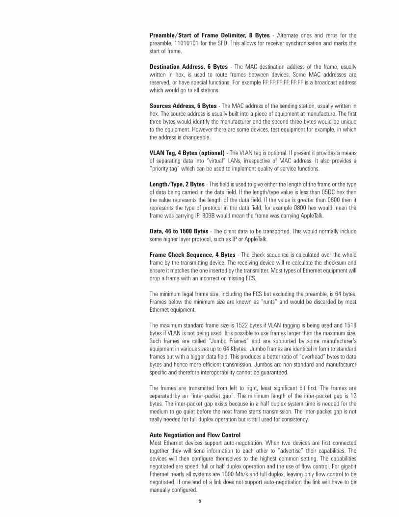
The structure of an Ethernet frame is:
The function of the various parts is as follows:
5
Preamble/Start of Frame Delimiter, 8 Bytes - Alternate ones and zeros for thepreamble, 11010101 for the SFD. This allows for receiver synchronisation and marks thestart of frame.
Destination Address, 6 Bytes - The MAC destination address of the frame, usuallywritten in hex, is used to route frames between devices. Some MAC addresses arereserved, or have special functions. For example FF:FF:FF:FF:FF:FF is a broadcast addresswhich would go to all stations.
Sources Address, 6 Bytes - The MAC address of the sending station, usually written inhex. The source address is usually built into a piece of equipment at manufacture. The firstthree bytes would identify the manufacturer and the second three bytes would be uniqueto the equipment. However there are some devices, test equipment for example, in whichthe address is changeable.
VLAN Tag, 4 Bytes (optional) - The VLAN tag is optional. If present it provides a meansof separating data into “virtual” LANs, irrespective of MAC address. It also provides a“priority tag” which can be used to implement quality of service functions.
Length/Type, 2 Bytes - This field is used to give either the length of the frame or the typeof data being carried in the data field. If the length/type value is less than 05DC hex thenthe value represents the length of the data field. If the value is greater than 0600 then itrepresents the type of protocol in the data field, for example 0800 hex would mean theframe was carrying IP. 809B would mean the frame was carrying AppleTalk.
Data, 46 to 1500 Bytes - The client data to be transported. This would normally includesome higher layer protocol, such as IP or AppleTalk.
Frame Check Sequence, 4 Bytes - The check sequence is calculated over the wholeframe by the transmitting device. The receiving device will re-calculate the checksum andensure it matches the one inserted by the transmitter. Most types of Ethernet equipment willdrop a frame with an incorrect or missing FCS.
The minimum legal frame size, including the FCS but excluding the preamble, is 64 bytes.Frames below the minimum size are known as “runts” and would be discarded by mostEthernet equipment.
The maximum standard frame size is 1522 bytes if VLAN tagging is being used and 1518bytes if VLAN is not being used. It is possible to use frames larger than the maximum size.Such frames are called “Jumbo Frames” and are supported by some manufacturer’sequipment in various sizes up to 64 Kbytes. Jumbo frames are identical in form to standardframes but with a bigger data field. This produces a better ratio of “overhead” bytes to databytes and hence more efficient transmission. Jumbos are non-standard and manufacturerspecific and therefore interoperability cannot be guaranteed.
The frames are transmitted from left to right, least significant bit first. The frames areseparated by an “inter-packet gap”. The minimum length of the inter-packet gap is 12bytes. The inter-packet gap exists because in a half duplex system time is needed for themedium to go quiet before the next frame starts transmission. The inter-packet gap is notreally needed for full duplex operation but is still used for consistency.
Auto Negotiation and Flow ControlMost Ethernet devices support auto-negotiation. When two devices are first connectedtogether they will send information to each other to “advertise” their capabilities. Thedevices will then configure themselves to the highest common setting. The capabilitiesnegotiated are speed, full or half duplex operation and the use of flow control. For gigabitEthernet nearly all systems are 1000 Mb/s and full duplex, leaving only flow control to benegotiated. If one end of a link does not support auto-negotiation the link will have to bemanually configured.
6
Flow control is only used in full-duplex mode and is achieved by sending PAUSE requeststo the station at the other end of an Ethernet link when a receiver is being overloaded withdata. Flow control can be either non-symmetrical, when only one station can issue pauserequests or symmetrical, where both stations can issue PAUSE requests. The PAUSE requestcontains a field that tells the far end station how long to stop transmitting for in order to givethe receiver an opportunity to catch up. If flow control is not being used data will be lostunder overload conditions.
Transmission SchemesVarious line-coding schemes are used to transmit Ethernet frames at the physical layer. For 100 BASE-X (TX or FX) a 4b/5b encoding scheme is used, giving a physical line rate of125 Mb/s. Other coding schemes are used to suit various media types.
For gigabit Ethernet the most common transmission scheme is the 8b/10b encodingscheme used for 1000BASE-X (CX, SX, LX), giving a line rate of 1250 Mb/s. As well ascoding data for transmission the 8B/10B scheme has special code groups, including a “lineidle” and a “start of frame”. This means that at the physical layer a gigabit Ethernettransmitter is always “on” and the receiver is always synchronised, even during the inter-packet gap. This, combined with full duplex operation, makes both the inter-packet gap andthe preamble redundant for gigabit Ethernet. However both are still used to provideconsistency of operation to the upper layers.
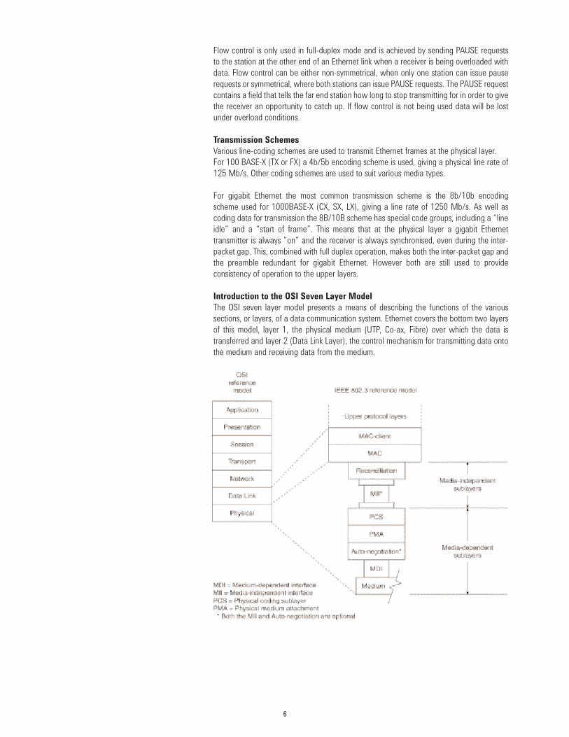
Introduction to the OSI Seven Layer ModelThe OSI seven layer model presents a means of describing the functions of the varioussections, or layers, of a data communication system. Ethernet covers the bottom two layersof this model, layer 1, the physical medium (UTP, Co-ax, Fibre) over which the data istransferred and layer 2 (Data Link Layer), the control mechanism for transmitting data ontothe medium and receiving data from the medium.
Layer 3 is the network Layer and this function is most commonly carried out by IP, butcould also be AppleTalk, IPX or other such protocols.
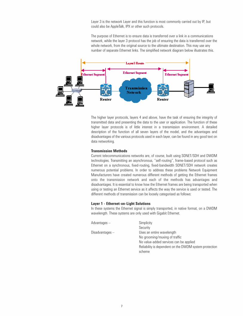
The purpose of Ethernet is to ensure data is transferred over a link in a communicationsnetwork, while the layer 3 protocol has the job of ensuring the data is transferred over thewhole network, from the original source to the ultimate destination. This may use anynumber of separate Ethernet links. The simplified network diagram below illustrates this.
The higher layer protocols, layers 4 and above, have the task of ensuring the integrity oftransmitted data and presenting the data to the user or application. The function of thesehigher layer protocols is of little interest in a transmission environment. A detaileddescription of the function of all seven layers of the model, and the advantages anddisadvantages of the various protocols used in each layer, can be found in any good text ondata networking.
Transmission MethodsCurrent telecommunications networks are, of course, built using SONET/SDH and DWDMtechnologies. Transmitting an asynchronous, “self-routing”, frame-based protocol such asEthernet on a synchronous, fixed-routing, fixed-bandwidth SONET/SDH network createsnumerous potential problems. In order to address these problems Network EquipmentManufacturers have created numerous different methods of getting the Ethernet framesonto the transmission network and each of the methods has advantages anddisadvantages. It is essential to know how the Ethernet frames are being transported whenusing or testing an Ethernet service as it affects the way the service is used or tested. Thedifferent methods of transmission can be loosely categorised as follows:
Layer 1 - Ethernet-on-Light SolutionsIn these systems the Ethernet signal is simply transported, in native format, on a DWDMwavelength. These systems are only used with Gigabit Ethernet.
Advantages – SimplicitySecurity
Disadvantages – Uses an entire wavelength No grooming/muxing of trafficNo value-added services can be appliedReliability is dependent on the DWDM system protectionscheme
7

8
Since no Layer2 switching is involved these systems can be expected to operate in adifferent manner to a “normal” Ethernet device. For example a layer1 system shouldpropagate errored frames rather than rejecting them.
Layer 1/2- Ethernet-in-SONET/SDH (Unswitched)In these systems the Ethernet frames are received by the equipment, encapsulated in someway and then transported as a SONET payload. The encapsulation can be done in a numberof ways; the most common methods are PPP over HDLC, GFP, LAPS or a proprietarymethod. See below for more details on encapsulation schemes.
These systems may incorporate some layer 2 “intelligence”, switching the Ethernet framesinto the correct SONET channel by using VLAN tags for example. Most of the currentsystems however simply send all received frames to SONET line-side and vice-versa.
The advantages and disadvantages of the unswitched method are:
Advantages – Does not use an entire DWDM wavelengthUses the SONET protection scheme
Disadvantages – Grooming/muxing/switching of traffic is not possibleSharing of line-side bandwidth is not possibleInefficient use of line-side bandwidth
Layer 2 - Ethernet-in-SONET/SDH (Switched)In these systems a layer 2 Ethernet (MAC) switch is built into the network element tributarycard. The SONET/SDH channel(s) that the Ethernet traffic are to be carried over are treatedby the switch as an “extra” Ethernet port, or ports, with the Ethernet frames beingencapsulated into SONET/SDH by using the same methods as the un-switched solution. AnEthernet switch will learn the MAC addresses of all the devices connected to it and thenroute frames to the correct port based upon the destination MAC address.
GbEIn/Out
DWDM LineOEO or WavelengthTranslator
Ethernet input
Ethernet input
Ethernet input
Ethernet input
SONET/SDHLine-Side
Mapper
Mapper

9
This method therefore allows for the switching/grooming and statistical multiplexing of theEthernet traffic. This gives far greater flexibility in allocating bandwidth on the line side ofthe device. A single line-side channel can now be used to serve several customers. Thisgreatly enhances the bandwidth efficiency when carrying a “bursty” Ethernet service thatat times may have no traffic on it. The downside to sharing of line-side bandwidth is thatwhen all of the customers are trying to access the service at the same time bandwidthcontention, with a consequent loss of traffic, will occur.
Advantages – Does not use a wavelengthUses SONET protection schemeAllows for efficient use of line-side bandwidthTraffic grooming and prioritisation is possible using VLAN or priority tags (If NE supports this)
Disadvantages – Shared bandwidth may lead to contentionShared bandwidth may have security concerns
Layer 3 - IP Switch/RouterA few systems have a layer3 switch incorporated into a SONET network element. Thesesystems are an extension of the switched layer2 solutions with the customer traffic beingsent to the correct port or SONET line-side channel based upon IP address instead of MACaddress. These systems have the same advantages as the layer 2 solutions. They also havethe additional benefit of negating the need for all the customers to have a router in a multi-tenant building environment. On the downside such devices can be difficult to provision andmanage.
EncapsulationThere are various methods of encapsulating Ethernet frames into a SONET/SDH bearer.Encapsulation is needed in order to ensure that the Ethernet frames are packaged in thecorrect format for transport. Encapsulation is used to mark the beginning and end of theframes and to deal with the interpacket gap between frames. The most commonencapsulation schemes are:
PPP over HDLC – Point-to-Point Protocol over High Level Data Link Control. This is theencapsulation method used to carry IP datagrams in Packet over SONET (PoS) systems. ForEthernet over SONET/SDH systems PPP/HDLC is simply used to carry Ethernet framesinstead of IP datagrams.
LAPS (ITU-T, X86.) – Link Access Protocol, SDH. This method of mapping has beenspecifically designed to carry Ethernet frames over SDH or SONET links. It is being adoptedby the ITU-T as a standard, number X86. It is very similar to HDLC in operation.
Ethernet input
Ethernet input
Ethernet input
Ethernet input
SONET/SDHLine-SideMapperEthernet
Switch

10
GFP – Generic Framing Protocol. As the name implies this method of encapsulation can beused to carry most types of data service, not just Ethernet.
Proprietary – Many manufacturers use their own encapsulation schemes. However mostof these schemes are simply variations on one of the methods described above.
Generally the manufacturer sets the type of encapsulation scheme and little needs to beknown about it during the installation and maintenance phases of network deployment.However the type of encapsulation scheme and how it is used can have an effect on thedata throughput rate and so it should not be ignored. For example GFP can have two modesof operation: framed or transparent. In transparent mode all the data from an incomingsignal, including the interpacket gap and the preamble, will be transported. This means thatline-side bandwidth is being used to transport “overhead” data. Conversely if GFP isoperated in framed mode it will only transport the actual frame and not the preamble or IPG.This can obviously lead to bandwidth efficiencies.
Most of the equipment currently available uses a proprietary encapsulation scheme,preventing interoperability between vendors. However many vendors are moving towardsLAPS or GFP. This should mean that future network equipment is inter-operable.
Testing Ethernet Services Service QualityThere is a perceived difference in the quality allowed for an Ethernet service compared toa SONET/SDH or T-Carrier/PDH service. In general for SONET/SDH or T-carrier/PDH anyerrors are considered significant and in some circumstances even a single bit error canaffect the quality of the end service.
Conversely, Ethernet has its origins in a shared medium environment where collisions, andsubsequent loss of data, are normal. In addition the discarding of packets by routers under“overload” conditions is a normal control mechanism. For this reason one of the primaryfunctions of the upper layer protocols is to ensure the completeness and correctness of thedata. Small amounts of data loss are therefore inconsequential and the data is simply re-transmitted, the re-transmit being initiated by the Ethernet layer if due to collisions or theupper layer protocol if due to frame loss. This leads to the belief that a lower quality ofservice can be acceptable for an Ethernet service when compared to a SONET/SDH service.While this is generally true it is still very important to set limits for the amount of errors ordata loss allowed and to be able to measure these limits.
The reason that quality of service is important for Ethernet is because as more data is lostthe number of re-transmits increases. This leads to more collisions/overloads and more dataloss, which in turn leads to more re-transmits and so on. This situation will very quickly makea network unusable. It is therefore necessary to keep the number of re-transmits to aminimum. In a shared-medium environment this is done by keeping the network utilisationlow and thus preventing collisions. In a full duplex environment this is done by minimisingthe number of errored or lost frames and thus preventing the upper layer protocolrequesting re-sending of data.
As with any other telecommunications service Ethernet services need to be tested. Testingthe service will ensure quality of service for the end user and optimum network utilisationfor the operator. The parameters to be tested and how they are measured are discussedbelow.

11
Parameters to be MeasuredThere are three fundamental measures of performance for data/Ethernet networks. Theseare:
• Data Throughput• Frame Loss• Latency
ThroughputData throughput is simply the maximum amount of data, usually measured in Mb/s, that canbe transported from source to destination. However the definition and measuring ofthroughput is complicated by the need to define an acceptable level of quality. For example,if 10% errored or lost frames were deemed to be acceptable then the throughput would bemeasured at 10% error rate. This document shall use the generally accepted definition thatthroughput should be measured with zero errors or lost frames.
In any given Ethernet system the absolute maximum throughput will be equal to the datarate, e.g.10Mb/s 100Mb/s or 1000Mb/s. In practice these figures cannot be achievedbecause of the effect of frame size. The smaller size frames have a lower effectivethroughput than the larger sizes because of the addition of the pre-amble and the inter-packet gap bytes, which do not count as data. The maximum achievable throughput forvarious frame sizes is given in the following tables
10Mb/s SystemData Preamble Frames
Frame Size Throughput and IPG Rate(bytes) (Mb/s) (Mb/s) (Frames/s)
64 7.62 2.38 14880
128 8.65 1.35 8445
256 9.27 0.72 4528
512 9.62 0.38 2349
1024 9.81 0.19 1197
1280 9.84 0.15 961
1518 9.87 0.13 812
1522 (includes VLAN) 9.87 0.13 810
100Mb/s SystemData Preamble Frames Frame Size Throughput and IPG Rate(bytes) (Mb/s) (Mb/s) (Frames/s)
64 76.19 23.81 148809
128 86.49 13.51 84459
256 92.75 7.25 45289
512 96.24 3.76 23496
1024 98.08 1.92 11973
1280 98.46 1.54 9615
1518 98.69 1.30 8127
1522 (includes VLAN) 98.70 1.30 8106

12
1000Mb/s SystemData Preamble Frames Frame Size Throughput and IPG Rate(bytes) (Mb/s) (Mb/s) (Frames/s)
64 761.90 238.10 1488095
128 864.86 135.14 844594
256 927.54 72.46 452898
512 962.40 37.59 234962
1024 980.84 19.16 119731
1280 984.61 15.38 96153
1518 986.99 13.00 81274
1522 (includes VLAN) 987.02 12.97 81063
On any system incorporating a layer2 switch throughput (and Frame Loss, see below) willbe affected by the way in which the service is used, or tested. This is because of over-subscription. For example, it is common to map a number, let’s say eight, of 10/100Mb/sEthernet services into a 622Mb/s SONET or SDH bearer. If we test, or use, only six portswe would expect to see full bandwidth available on all six ports. If we now re-test with alleight ports fully loaded there will only be approx 622/8 = 77Mb/s available on each portand this is what our throughput test would reveal. In addition if PAUSE flow control is notbeing used between the network element and the customer equipment/test set then the“extra” 23Mb of data will be lost.
Frame LossFrame loss is simply the number of frames that were transmitted successfully from thesource but were never received at the destination. It is usually referred to as frame loss rateand is expressed as a percentage of the total frames transmitted. For example if 1000frames were transmitted but only 900 were received the frame loss rate would be:
(1000-900) / 1000 x 100% = 10%
Frames can be lost, or dropped, for a number of reasons including errors, over-subscriptionand excessive delay.
Errors - most layer2 devices will drop a frame with an incorrect FCS. This means that asingle bit error in transmission will result in the entire frame being dropped. For this reasonBER, the most fundamental measure of a SONET/SDH service, has no meaning in Ethernetsince the ratio of good to errored bits cannot be ascertained.
Oversubscription - the most common reason for frame loss is oversubscription of the availablebandwidth. For example, if two 1000Mb/s Ethernet services are mapped into a single 622Mb/sSONET/SDH pipe (a common scenario) then the bandwidth limit is quickly reached as the twogigabit Ethernet services are loaded. When the limit is reached, frames may be dropped.
Under these circumstances it might be necessary to know not only how many frames arebeing dropped but which frames. For example, some network elements claim to be able toprioritise traffic based upon VLAN ID or priority tag. If this function is being used then as thebandwidth limit is reached it should be the low priority packets which get dropped. Thisfunctionality needs to be tested.
Excessive Delay - The nature of Ethernet networks means that it is possible for frames tobe delayed for considerable periods of time. This is important when testing as the tester is“waiting” for all of the transmitted frames to be received and counted. At some point thetester has to decide that a transmitted frame will not be received and count the frame aslost. The most common time period used to make this decision is the RFC specification oftwo seconds. Thus any frame received more then two seconds after it is transmitted wouldbe counted as lost.

13
LatencyLatency is the total time taken for a frame to travel from source to destination. This totaltime is the sum of both the processing delays in the network elements and the propagationdelay along the transmission medium.
In order to measure latency a test frame containing a time stamp is transmitted through thenetwork. The time stamp is then checked when the frame is received. In order for this tohappen the test frame needs to return to the original test set by means of a loopback(round-trip delay) or the test frame needs to be read by a similar set at the other end of thenetwork path.
If a single test set on loopback is to be used then the “out” and “return” paths need to besymmetrical in order for the measurement to be accurate. Whether this is the case dependsup on the capabilities of the network under test. If separate test sets are used then somemeans of synchronising the two sets to a single time source will be required. The onlypractical means of doing this is to synchronise the two test sets using GPS receivers but thiscan be difficult to achieve in practice due to the need for the GPS antenna to have a clearview of the satellites. Which of the two techniques needs to be used to measure latency willdepend upon the capabilities and setup of the device/network under test.
In a pure-data network operating at Layer3 it will probably be necessary to measure latencyend-to-end in order to achieve an accurate figure. There are several reasons for this. Firstly,the processing delays in the network elements, routers, can be considerable and will varydepending upon a number of factors including load and the size of the routing tables.Secondly, if more than one route is available to the router there is no guarantee that packetswill be sent by the same physical route “out” and “return”. Finally, if traffic management isbeing used then the router will delay “ordinary” traffic, possibly including the test frame, toallow high priority traffic such as voice-over-IP through. These factors mean that the “out”and “return” routes will almost certainly not have a symmetrical delay and the end-to-endmethod must be used.
However, the networks being examined in this paper are not pure-data networks butEthernet over SONET/SDH transmission networks. In addition, with a few exceptions, thesenetworks will operate at Layer2 or below. This means the loopback method for testinglatency can usually be used.
In a transmission network operating at Layer2 the processing delays inside the networkelements should be relatively small, when compared to the propagation delays. Forexample the time taken for a bit to propagate down one kilometre of fibre is approximately3.33µs (this, rather crudely, ignores the refractive index of the fibre). For 1000Mb/sEthernet the bit time is 1ns. This gives the network element 3300 bit times to carry outprocessing and switching before the processing delays become greater than thepropagation delays, even on very short fibre runs
Layer2 switching is relatively simple compared to Layer3 and it should not be affected byfactors such as loading. Therefore the time taken to process frames should be roughlysymmetrical in both the “out” and “return” directions. In addition for an Ethernet overSONET/SDH link the physical paths will be the same in the “out” and “return” directions.
Since the propagation delays should be very large compared to the processing delays, thusswamping any small variation that does occur in the processing times, and the physicalpaths are identical it is safe to assume that the “out” and “return” delays will besymmetrical for an Ethernet over SONET/SDH system. This means that the complications ofend-to-end latency measurements can be avoided and hence the simpler loopback methodcan be used.

14
Other MeasuresAs well as these fundamental measures there are many other parameters that may need tobe tested. These include:
• Counts of errored frames• Counts of out of sequence frames, • Counts of runt frames• Counts of jumbo frames• Counts of broadcast frames• Counts of multicast frames
As with the fundamental parameters the methods used to measure these parameters, andthe results obtained, will depend upon the capabilities and setup of the network under test.
Errored frames - These are Ethernet frames with an incorrect or missing FCS. Devicesoperating at layer2 will simply reject errored frames and testing such a device would showa dropped frame rather than counting an errored frame. On some layer1 solutions howeverit is possible to transmit and receive errored frames.
Out of Sequence frames - At layer3 it is possible for some frames to be delayed to allow theprioritisation of other traffic and out of sequence frames are possible. At layer2 or below outof sequence frames should not normally be encountered. However a frame that arrives afterthe test set has made the decision that the frame is lost (see “Frame Loss” section, above)will count as an out of sequence frame, provided the test set is capable of dealing with suchevents.
Runts - These are frames below the minimum frame size of 64 bytes. As with erroredframes, most devices will reject runts and a lost frame will be counted instead. Somedevices will however allow the transmission of runts so they may need to be counted.
Jumbo Frames - These are frames above the maximum size of 1518/1522 bytes. They mayor may not be allowed in the network depending upon configuration. If the switches do notallow them then they would be dropped and a lost frame would result when testing.
Broadcast/Multicast Frames - Broadcast and Multicast frames can use up a lot of networkbandwidth and for this reason some operators will restrict their use. For example broadcastscould be restricted to 5% of overall bandwidth. If this is being done then it will be requiredto count broadcast frames.
The tests highlighted above are the most common but not all possible requirements arecovered. For example, it may also be necessary to be able to test the response of the deviceor network under test to different MAC addresses, or its ability to handle VLAN tagging. Theneed for these “other” tests will depend upon many factors including the functionality ofthe device/network under test, the nature of the service being tested, the expectations ofthe end-user and the availability of test equipment. These factors should be borne in mindwhen designing test scenarios.
Test Methods When testing any telecommunications service it is necessary to transmit test traffic into thenetwork and then receive the test traffic either back on the original test set or on a similardevice at the “other end” of the service being tested. In this way the test set can measurewhat effect travelling through the network has had on the test traffic.
In a SONET/SDH network the most usual method of achieving this is to apply a transmitterto receiver loopback at the far end and test the service around this loop. For multi-portservices, tributaries can be “daisy-chained” to speed testing as long as jitter build up istaken into account.
15
With most types of network element this test methodology will not work for Ethernetservices and other methods must be used. Which test methods will work and which will notdepends upon the method being used to transport the Ethernet frames across theSONET/SDH network and the set-up of the network element(s).
Ethernet frames are routed based upon their MAC address. Ethernet switches, such asthose built into some network elements, need to “learn” what MAC address is connectedto a port before they will send any traffic to that port. If the transmitter is looped to thereceiver the switch will never see a frame being received to learn the MAC address and sowill not transmit any frames to the port. This also applies to a port-to-port loopback althoughit is sometimes possible to overcome this problem by correct use of VLAN tags. This meansthat Ethernet tributary cards, unlike their SONET/SDH equivalents, cannot be “daisy-chained” to reduce test time. A multi-port test set is therefore required if test time is to bekept to a minimum.
The methods outlined below are general examples but their use will depend on thecircumstances.
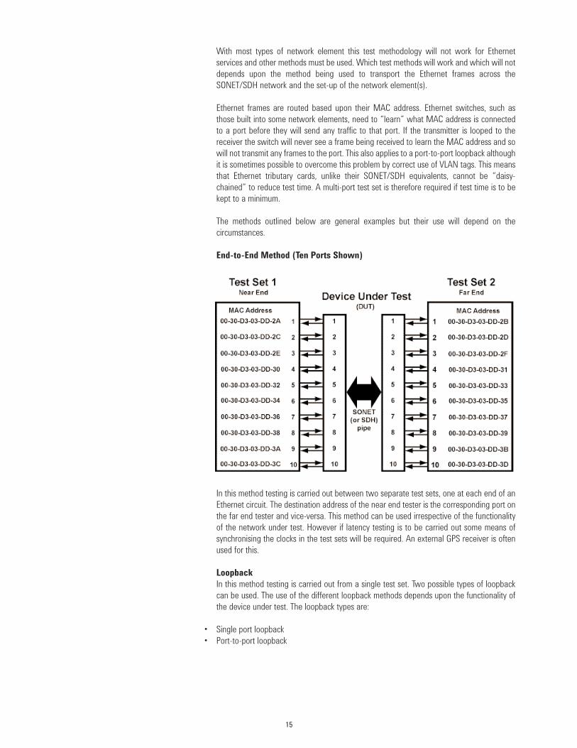
End-to-End Method (Ten Ports Shown)
In this method testing is carried out between two separate test sets, one at each end of anEthernet circuit. The destination address of the near end tester is the corresponding port onthe far end tester and vice-versa. This method can be used irrespective of the functionalityof the network under test. However if latency testing is to be carried out some means ofsynchronising the clocks in the test sets will be required. An external GPS receiver is oftenused for this.
LoopbackIn this method testing is carried out from a single test set. Two possible types of loopbackcan be used. The use of the different loopback methods depends upon the functionality ofthe device under test. The loopback types are:
• Single port loopback• Port-to-port loopback

16
In a single port loopback the tester is connected to the near end port(s) of the device undertest and a Tx-Rx loop is applied to the far end. This method only works with networkequipment that operates at Layer1, such as some Ethernet-on-light solutions. It will notnormally work with a Layer2 Ethernet device, as the port at the far end will be unable toroute the test frames. This method requires the source and destination MAC addresses tobe the same and so will not be supported by all types of test set.
Single Port Loopback
Port-to-Port Loopback
In a port-to-port loopback the tester is connected to two (or more) near end ports and theloopback is applied from port to port at the far end. This method only works on networkequipment that operates at layer1. If a port-to-port loopback is applied to a networkelement that contains an Ethernet switch then the test frames will not be sent back to thetester because the switches will not be able to resolve the MAC addresses correctly.

A port-to-port loopback can be made to work on some networks by using VLAN tags. Thisis achieved by provisioning the network elements such that port1 on the near end has apath to port1 on the far end and port2 on the near end has a path to port2 on the far end.Both Port1s are then placed in VLAN 1 and both port2s are placed in VLAN 2. This isillustrated below.
Test frames are then sent into the network element, port1 with a destination MAC addressof the second port on the tester. The switch will tag the frames as VLAN 1 when they arereceived on port 1. The switch will not simply send the frames to port 2, even though theMAC address matches, because the switch has been told that port 2 is in VLAN 2 and theframes are now tagged as VLAN 1. The frames will therefore be sent to the far end. At thefar end the switch will not recognise the destination MAC address so will broadcast theframes to all VLAN 1 ports, in this case port 1. Port 1 is cabled to port 2 so the frames willbe received on port 2, where they will be re-tagged as VLAN 2. The switch once again willnot be able to associate the MAC address with VLAN 2 so will send the frames line-side.The frames will now be received back at the near end, tagged as VLAN 2. The near-endswitch will now associate the MAC address with VLAN2, port 2 and will send the frames toport 2 where they will be received by the tester, just as required. Frames that are sent fromport 2 on the tester to port 1 would be treated in a similar manner.
As can be seen this method, if it can be made to work, requires a lot of provisioning. Thisincludes the provisioning of some paths which may already be in use for customer traffic, inwhich case this method cannot be used.
LoopthroughLoopthrough is a phrase coined by Agilent Technologies to describe the functionalityavailable on some of its Ethernet test equipment. This functionality will not be available onall test sets. The method works as follows:
This method uses two testers, one at each end of the Ethernet circuit. However the far endtester does not actively test the circuit. The far end instrument simply acts as a“loopthrough”. It will receive the test frames and strip the source and destination MACaddresses. It then re-inserts the source address as the destination address and vice-versabefore re-transmitting the frames.
17
Test Set
Port 1
Port 2
Port 3
Port 4
Port 1
Port 2
Port 3
Port 4SONET/SDH Line
VLAN2
VLAN1

18
Using this method it is possible for all tests to be carried out, including latency, on a singlecircuit, without the provisioning of extra paths through the network or the use of VLAN tags.
Loopthrough
Test Method SummaryThe advantages and disadvantages of the different test methods are summarised in thetable below.
Method Advantages Disadvantages
End-to-End Can be used on a single circuit. Requires two unitsCan be used to isolate Requires two operatorsunidirectional faults Latency measurement is
not possible
Loopback Can be used on a single circuit Only works on some types of(Single Port) Only requires one instrument network equipment
and one operator
Loopback Only requires one instrument Requires the provisioning of(Dual Port) and one operator a second circuit and/or the
use of VLAN tagsOnly works on some typesof network equipment
Loopthrough Can be used on a single circuit Requires the use of twoAll measurements available instrumentsOnly requires one operator once set-up.Works on all types of network equipment

19
An ExampleThe results below were obtained while testing an Ethernet service on a multi-serviceplatform. The platform in question is of the layer2 variety with multiple Ethernet “input”ports, a layer2 switch and a line-side “output” port. The line-side ports are connectedtogether across the network by the provisioning of an SDH pipe of various sizes. The pipesize used in the results below was a C-12 (2.176Mb/s). The tests were run on a single portusing the end-to-end test method.
Frames SentRate (Mb/s) Frame Size
64 128 256 512 1024 1500
1.024 120000 60000 30000 15000 7500 5100
1.4 164040 82020 40980 20460 10200 6960
1.536 180000 90000 45000 22500 11220 7680
1.7 199200 99600 49800 24900 12420 8460
2 234360 117180 58560 29280 14640 9960
2.048 240000 120000 60000 30000 15000 10200
2.5 292920 146460 73200 36600 18300 12480
5 585900 292920 146460 73200 36600 24960
10 1171860 585900 292920 146460 73200 49980
Frames ReceivedRate (Mb/s) Frame Size
64 128 256 512 1024 1500
1.024 120000 60000 30000 15000 7500 5100
1.4 164040 82020 40980 20460 10200 6960
1.536 169919 90000 45000 22500 11220 7680
1.7 169990 99600 49800 24900 12420 8460
2 170083 102092 56718 29280 14640 9960
2.048 170095 102098 56761 30000 15000 10200
2.5 169410 101934 56718 30092 15549 10749
5 169443 101676 56679 30074 15549 11189
10 169435 101698 56537 30050 15541 10748
Frames LostRate (Mb/s) Frame Size
64 128 256 512 1024 1500
1.024 0.00% 0.00% 0.00% 0.00% 0.00% 0.00%
1.4 0.00% 0.00% 0.00% 0.00% 0.00% 0.00%
1.536 5.60% 0.00% 0.00% 0.00% 0.00% 0.00%
1.7 14.66% 0.00% 0.00% 0.00% 0.00% 0.00%
2 27.43% 12.88% 3.15% 0.00% 0.00% 0.00%
2.048 29.13% 14.92% 5.40% 0.00% 0.00% 0.00%
2.5 42.17% 30.40% 22.52% 17.78% 15.03% 13.87%
5 71.08% 65.29% 61.30% 58.92% 57.52% 55.17%
10 85.54% 82.64% 80.70% 79.48% 78.77% 78.50%

20
Round Trip Delay (ms)Rate (Mb/s) Frame Size
64 128 256 512 1024 1500
1.024 20 10 10 11 20 20
1.4 40 20 21 20 40 21
1.536 60 20 20 30 21 20
1.7 51 31 21 20 30 21
2 60 80 121 30 31 21
2.048 60 80 121 40 40 21
2.5 60 80 130 230 401 561
5 60 80 131 220 401 571
10 61 90 131 220 401 571
These results are very interesting. At the larger frame sizes no frame loss is encountereduntil we reach the bandwidth limit of the SDH bearer. At the smaller frame sizes we seesubstantial frame loss before we reach the bandwidth limit. This is most likely due to theframe processing software in the network element being unable to keep up with the largenumber of frames present at small sizes.
The latency/round trip delay results are also very interesting. These show a distinct step,particularly at larger frame sizes, when the bandwidth limit is reached. It is not possible tospeculate on the reason for this without more information on how the network element isoperating.

21
Summary Ethernet has become a transport protocol in telecommunication networks. The use of nativeEthernet interfaces on telecommunications transmission equipment can bring cost savingsto the end customer and revenue to the network operator. It can also offer simplicity andease-of-use.
In order to deploy the technology and realise these benefits an understanding of how thetechnology works and how to test it is required. Ethernet differs from the “traditional”SONET/SDH and DSn/PDH services and these differences have to be taken intoconsideration. If this is done then the “next generation” of data-ready network elementscan help network operators meet their customers needs and maximise revenue from theirnetworks.

22
Notes

23
Notes

www.agilent.com
Together with Agilent, gain the Extreme ProductivityImprovements that your business demands!
www.agilent.com/comms/XPI
Online assistance: www.agilent.com/find/assistBy internet, phone or fax, get assistance withall your test and measurement needs.
Argentina +54 11 5811 7115Australia 1 800 629 485Austria +43 (01) 25 125 7006Belgium +32 (0) 2 404 9340Brazil +55 11 4197 3600Canada-English 877 894 4414Canada-French 877 894 4414China 800 810 0189Denmark +45 70 13 15 15Finland +358 (0) 10 855 2100France +33 (0) 825 010 700Germany +49 (0) 18 05 24 63 33Hong Kong 800 930 871India 1600 112 929Ireland +353 1890 924 204Israel +972 3 6892 500Italy +39 02 92 60 8484Japan 0120 421 345Luxemborg +32 (0) 2 404 9340Malaysia 1800 888 848Mexico +52 01800 506 4800Netherlands +31 (0) 20 5472111Norway +47 23 25 3720Philippines 1800 1651 0170Poland +48 22 723 0066Russia +7 095 797 3963Singapore 1800 375 8100South Korea 080 769 0800Spain +34 91 631 3300Sweden 0200 88 22 55Switzerland-German +41 (0) 1 735 9300Switzerland-Italy +39 (0) 2 92 60 8484Switzerland-French +33 (0) 825 010 700Taiwan 0800 047 866Thailand 1800 226 008United Kingdom +44 (0) 7004 666666USA 800 452 4844
Product specifications and descriptions in thisdocument are subject to change without notice.
© Agilent Technologies, Inc. 2000-2002Printed in U.S.A. October 12, 2002
*5988-7800EN*5988-7800EN


