Communication System - NASA
60
- ..a Communication System The communication system equipment and configuration are identical to those of the basic Apollo. It is augmented by a speaker box and configuration changes to facilitate cluster operation. The unique Skylab requirement is again in the extended operating time for a portion of the communications system. This includes the audio center, unified S-band equipment, premodulation processor, and up-data link. These units all use solid-state devices, having 100 percent derating, and preusage burnin screening as well as equipment burnin of 100 hours. Based on this justified extrapolation of pre- viously demonstrated operating life to meet Skylab requirements was possible. Ordnance Systems Of the numerous devices used on the CSM, the Panel’s interest centered on the CM-SM separation system. This system is located external to the CM and between the aft heat shield of the CM and forward bulkhead of the SM. CM separation from the SM takes place during all abort phases and after orbital flight before CM reentry. The Apollo RDX type tension tie cutter did not pass the Skylab thermal vacuum verification test. Detonation energy available for cutting was low. The RDX was replaced with a HNS silver sheathed shaped charge. At the time of Panel review the replacement was undergoing test certification. Failure of the tension tie cutter to separate the CM and SM is critical, and a qualified tension tie cutter must be ,available. The closure of this item will be enclosed in the next report. Based on the material presented to the Panel, management controls are still in effect to assure hardware of high quality. ORBITAL WORKSHOP Background Description The orbital workshop is a two-floor structure providing accommodations for the crew and a primary experiment area. The first floor is divided into four sections: the sleep compartment, the waste management compartment, the wardroom, and the experi- ment work area. The biomedical experiments are performed in the experiment work area. The second floor is devoted primarily to experiments which require relatively large volumes or which use either of two scientific airlocks for external viewing or ex- posure. The remainder of the space is occupied by subsystem and storage compart- ments. These arrangements are shown in figures 18 and 19. 51
Transcript of Communication System - NASA

- ..a
Communication System
The communication system equipment and configuration are identical to those of the
basic Apollo. It is augmented by a speaker box and configuration changes to facilitate
cluster operation. The unique Skylab requirement is again in the extended operating
time for a portion of the communications system. This includes the audio center,
unified S-band equipment, premodulation processor, and up-data link. These units all
use solid-state devices, having 100 percent derating, and preusage burnin screening as
well as equipment burnin of 100 hours. Based on this justified extrapolation of pre-
viously demonstrated operating life to meet Skylab requirements was possible.
Ordnance Systems
Of the numerous devices used on the CSM, the Panel’s interest centered on the
CM-SM separation system. This system is located external to the CM and between the
aft heat shield of the CM and forward bulkhead of the SM. CM separation from the SM
takes place during all abort phases and after orbital flight before CM reentry. The
Apollo RDX type tension tie cutter did not pass the Skylab thermal vacuum verification
test. Detonation energy available for cutting was low. The RDX was replaced with a
HNS silver sheathed shaped charge. At the time of Panel review the replacement was
undergoing test certification. Failure of the tension tie cutter to separate the CM and
SM is critical, and a qualified tension tie cutter must be ,available. The closure of this
item will be enclosed in the next report.
Based on the material presented to the Panel, management controls are still in
effect to assure hardware of high quality.
ORBITAL WORKSHOP
Background Description
The orbital workshop is a two-floor structure providing accommodations for the
crew and a primary experiment area. The first floor is divided into four sections: the
sleep compartment, the waste management compartment, the wardroom, and the experi-
ment work area. The biomedical experiments are performed in the experiment work
area. The second floor is devoted primarily to experiments which require relatively
large volumes or which use either of two scientific airlocks for external viewing or ex-
posure. The remainder of the space is occupied by subsystem and storage compart-
ments. These arrangements are shown in figures 18 and 19.
51

Access \
Food Freezer Storage
waste Management
Compartment Fan
Solar Array System Beam Fairing
Sleep
Compartment
Waste
Management Compartment -
Wardroom
Food Management - /-y-XL
Waste
FIGURE 18 - ORBITAL WORKSHOP
52

CabIn Atmosphere Distribution Ducts
Water Tanks
Storage Lockers
Film
Compartment Divider Grid
structure
Bio-Medical
Experiment Work Area
L Thruster Gas SUPPlY
.
FIGURE 19 - ORBITAL WORKSHOP
53

The workshop also is the storage area for crew supplies, such as food, water, and
clothing, as well as providing for personal hygiene and waste and trash disposal.
The OWS is an S-IVB stage of the Saturn V launch vehicle that is ground outfitted
to be suitable for manned habitation.
The OWS structure provides for
1. Habitable environment with crew provisions and consumables
2. Capability for experiment installation
3. Support for conducting experiments
4. Propulsive capability for attitude control
5. Solar array power source, mounting provisions for the array, and routing of
6.
7.
8.
9.
10.
power to the airlock module
Storage for cluster waste material
Capability for orbital storage and reuse
Two scientific airlock installations, one on the cluster -Z axis (Sun side) and one
on the cluster +Z axis (dark side)
Capability for television transmission via MDA video selector and CSM transmit!
No scheduled or planned activity requiring access into the habitable volume of
OWS after closeout in the Vehicle Assembly Building
For launch, the OWS consists of an S-IBV/S-V forward skirt, S-IVB propellant
tanks with preinstalled crew and experiment accommodations, and an S-IVB-S-V aft
skirt and interstage. The forward skirt interfaces with the IU, the forward tank dome
interfaces with the AM, and the aft interstage interfaces with the S-II stage. The in-
orbit configuration is essentially the same. The only changes are that the interstage
separates with the S-II stage, and the solar array and meteoroid shield are deployed.
Significant changes to the S-IVB structure have been caused by Skylab require-
ments. Provisions have been made for an OWS vacuum outlet, scientific airlock (SAL)
and attachments for crew quarters, experiments, and equipment stowage. A waste dun;
airlock has been provided in the common bulkhead area for disposing of wet and dry
waste through the common bulkhead from the LH2 tank to the LOX tank.
A meteoroid shield is designed as a structurally integrated part of the OWS and
protects the cylindrical portion of the tank. After deployment, the shield extends abou
6 inches radially from the outer surface of the LH2 tank. Deployment is accomplished
during orbit by a signal from the IU.
The S-IVB is divided into a two-level crew quarters by a structure serving as a
floor/ceiling installed in the LH2 tank, perpendicular to the longitudinal axis of the
S-IVB stage. The section aft of the floor/ceiling provides the crew with accommoda-
tions for sleeping, food and waste management, hygiene activity, off-duty activity, da
management, and the implementation of corollar experiments.
Astronaut mobility/stability aids have been installed to assist the astronauts in
performing tasks associated with activation, crew habitation, experimentation, and dc
54
.- --- ._ ..-

activation. These aids are of two basic types - fixed and portable. Fixed astronaut
aids include handrails, tether attach devices, and the central handrail. They are per-
manently installed in locations throughout the LH2 tank where it is expected that heavy
traffic or task loading will occur. Portable astronaut aids include handholds, tether
attach brackets, and foot restraints. OWS interior lighting allows for crew equipment installations, normal and emer-
gency crew activities, and experiment operations. The interior lighting system con-
sists of initial-entry lights, general-illumination lights, emergency lights, and special-
purpose lights. Orientation (running) lights are provided for determining the gross
attitude of the passive vehicle and movement relative to a line of sight through the win-
dow of the docking vehicle. In addition, white floodlights will be used to illuminate the
exterior of the cluster and the exterior of the AM within the thermal curtains. A port-
able floodlight is used by the astronaut during EVA.
The subsystems comprising the total OWS include the following for our purpose:
Panel examined in detail Panel made cursory examination
Structures subsystem
Environmental and thermal control sub-
system
Electrical power subsystem - (EMC and
corona)
Thruster attitude control subsystem
Solar array subsystem
Ordnance subsystem
Ground support equipment subsystem
Communications and data acquisition system
Caution and warning subsystem
Habitability support subsystem
Crew equipment subsystem
Three systems were reviewed on the following occasions: (1) MDAC-West, October
1971, (2) Marshall, April 1972, (3) PDTR, April 1972, and (4) DCR, October 1972. The
Panel in its factfinding was interested in the evident effectiveness of the technical man-
agement systems, the maturity of the design, and the quality of the hardware. The
following discussion is based on these factfinding reviews.
Note should be made that experiments and other modules are discussed here only as
they present interface requirements. They are discussed in detail elsewhere.
Orbital Workshop Hardware
The OWS flight hardware checkout began November 6, 1971 with the start of
continuity/compatibility testing. It continued through completion of the all systems test,
electro/magnetic compatibility test, and residual subsystem retests August 16, 1972.
55

During this period, all subsystems, crew compartment fit and function (C”F’), and the
combined all systems test and electro/magnetic compatibility (AST and EMC) test were
performed.
The crew compartment fit and function was conducted in two increments. The first increment ran May 22 through 28, and the second increment August 12, 1972. Some
C2F2 checkout remains to be accomplished at KSC primarily because of lack of hard-
ware, notably in the stowage area.
The combined AST and EMC test was performed July 17 through August 7, 1972.
This test functioned each OWS system on a simulated prelaunch, launch, and orbital
time line to verify systems compatibility throughout the mission profile.
Further checkout activities included a mercury certification of the habitation area
and calibration of the meteoroid shield strain gages. Major manufacturing activity
focused on modification of the meteoroid shield and cleanup activities associated with
final inspection. The spacecraft was moved to Seal Beach for thruster attitude control
system proof testing on August 31, 1972. Final preparations for shipment followed at
Huntington Beach.
Problems encountered during this checkout were documented on test problem re-
ports. A summary of the closeout status of these reports is shown in table VI. Some
test problems could not be closed at Huntington Beach because of unavailable hardware
and unfurnished rework and testing. These are transferred to a recap test problem
report which identifies the problem being transferred to KSC, the reason the problem
was not resolved at Huntington Beach, and the applicable documentation (i. e. , failure
report, discrepancy report, inspection item sheet, original test problem report).
The retest outline is the document that identifies, at the time of shipment, open re-
test and/or test requirements of incompleted assemblies, discrepancy reports, failure
reports, and removals and requires quality assurance verification for final buy-off. It contains three categories:
(1) Retest required as a result of assemblies, failure reports, discrepancy reports
and removals that were worked after factory testing
(2) A listing of unworked assembly outlines, engineering orders, etc.
(3) A line item to identify the recap test problem report and associated test or rete
requirements that must be transferred to KSC
All items associated with open work are listed in the data package contained as a part of the certificate of flight worthiness and DD250 form.
There were 27 OWS design certification review (DCR) review item discrepancies
(RID’s). Essentially all are closed at this time.
All test objectives have been satisfied except those noted in table VII.
56
--I . -. , .-_.

Orbital Workshop Structures Subsystem
. .
The OWS structures subsystem consists of the following major components:
1. Forward skirt which serves as structural continuation between OWS habitation
area tank and the IU. It provides space for mounting electrical and electronic equip-
ment as well as providing support for the solar array system wing assemblies. There
appeared to be no unique fabrication techniques or new technology applied here. The
major items requiring assurance were the SAS attachment provisions which support
these most important electrical power generating components. At the time of the formal
DCR there were no open items, waiver, or deviations associated with the forward skirt,
and it complied with the MSFC hardware safety checklist. McDonnell Douglas-West
expects little or no work to be done at the KSC on this item.
2. Thermal shield. The thermal shield, attached to the aft 34 inches of the forward
skirt, functions as a radiator barrier to aid in stabilizing the habitation area tempera-
ture. There appear to be no constraints to mission or crew safety attached to this item.
3. Aft skirt and thermal shield. The aft skirt is a modified Saturn V/IVB aft skirt.
Structural capabilities apparently were not changed by OWS modifications. The attach-
ment of the aft thermal shield is similar to that for the forward thermal shield. This
skirt also has attachments to support the SAS installation. The OWS flight loads are
indicated as lower than those for the S-IVB aft skirt and there was no indication of any
problems. During development of this structure, the thruster attitude control subsystem
nozzles which are hard mounted to this structure had to be modified to a shock-mount
to preclude damage to nozzle valves. Analysis and test results show no waivers or
specification deviations required.
4. Aft interstage. This is a frustum-shaped assembly which transmits loads be-
tween OWS aft skirt and S-II stage and provides the OWS radiator assembly protection
during launch. It remains with the discarded S-II stage. There appear to be no con-
straints caused by this item.
5. Thrust structure. This is a multipurpose structure using the basic S-IBV stage
with modifications to support the thruster attitude control subsystem’s nitrogen gas
storage spheres and associated piping, the subsystem’s meteoroid protection shield,
and the refrigeration system radiator with its impingement shield and structural sup-
port. Some items of note are the single failure points associated with the thruster
attitude control system.
(a) Rupture or bursting of the thruster attitude control subsystem’s storage and
manifold could jeopardize the safety of the crew.
(b) Radiator shield actuator assembly release mechanism failure could preclude
jettison of radiator shield adversely affecting OWS thermal control system opera-
tion .
57
A
- -. .

These single failure points appear acceptable based on the added manufacturing and
quality controls imposed, tests and analysis conducted, and similarity to prior use on
Saturn launch vehicles.
6. Meteoroid shield. This shield for the habitation area is composed of cylindrical
sections. When deployed they act as the outer barrier with the OWS main tank wall as
the inner barrier. The standoff distance of this meteoroid shield is approximately
5 inches. It is deployed on-orbit by severing tension straps with expandable ordnance
tubes and moved outward by 16 links powered by independent torsion bars.
Meteoroid shield deployment was successfully demonstrated at NASA/MSFC, How-
ever, during pressure testing one of the shield hinges failed structurally. The hinge
subsequently was redesigned and the strength capability verified by tests. These de-
sign changes have been incorporated into the OWS. The static test article (STA) is to
be reworked and retested at NASA/MSFC during the October to November time frame
and these test results should be verified.
Verification of the structures subsystem was demonstrated by the satisfactory com-
pletion of all subsystem testing.
A further deployment production acceptance test is expected to be conducted at
KSC.
7. Habitation tank. This “habitation or crew area” consists of a forward dome,
main cylindrical section with window and door openings, and an aft common bulkhead
forming the “lower floor. ” The interior-is insulated with polyurethane foam covered
with an aluminum foil-fiberglass-teflon type liner. In addition, the external surface of
the forward dome is covered with insulation consisting of some 95 layers of aluminized
mylar with interspersed layers of separator sheets, while the cylindrical portion is
coated with a reflective coating. The Panel’s interest here was the structure’s ability to support onboard equipment
particularly through the SL-1 launch period and to maintain onboard pressure within the
allowable atmospheric gas leakage (OWC decompression). The allowable leakage rate
has been set at no more than 5 pounds mass per day in orbit. Table VIII indicates the
expected leakage allowances for hatches and penetrations. In line with this approach the
Panel identified the following areas which are discussed here:
1. Scientific airlock. It is used with experiments S-063 and S-190B. The scientific
airlock provides vacuum source and allows deployment of experiments outside the
habitation area. There are two ports, one on the solar side and one on the anti-solar
side.
2. Forward dome entry hatch. It is located at the apex of the dome and provides
for workshop entry in orbit. It functions as a structural part carrying pressure loads
during boost.
3. Side access panel. It provides ground access into the OWS module for installa-
tion and work on such items as experiments, water containers, food containers, etc.
58

4. Wardroom viewing window. It is of a double pane construction approximately
18 inches in diameter to allow simultaneous viewing by two crewmen. The design in-
cludes thermal and meteoroid protection when not in use.
5. Trash disposal airlock. It is a passthrough chamber built into the waste tank
common bulkhead. A failure poses both a potential pressure loss and microbial con-
tamination problem.
6. Water bottles and stowage container support structure. It provides for large
mass loads subject to static and launch acceleration loads. This is a good representa-
tion of all such structural loads.
The scientific airlock has a window which is the refurbished Apollo window and its
failure, as with the scientific airlock doors, would jeopardize the safety of the crew.
The inboard face of the scientific airlock has an opening which can be sealed by an ex-
periment or a window cover. Because of this the Panel feels that procedures for both
flight and ground operations must be explicit in the use of the scientific airlock. For
example, flight procedures should specify that the crew must be certain that the experi-
ments are indeed tightly situated against the scientific airlock to preclude leakage as the
experiment becomes a part of the airlock pressure vessel.
Since the inner and outer surfaces of the assembly have highly effective antireflec-
tive coatings, special care is required during ground operations.
The low temperatures on the anti-solar side made a desiccated repressurization
necessary to preclude humidity problems. Recent authorization for this resulted in a
new design which is still undergoing qualification tests. These are scheduled for com-
pletion in November and to date indicate no problems are expected.
Precise alinement of the individual scientific airlock is apparently difficult because
of deflections due to thermal, gravity, and pressure environments. Alinement must be
done at KSC.
KSC is aware of the measurement work which they have to accomplish. In reviewing
the scientific airlock structure it appears that it is capable of meeting its design re-
quirements.
However, an item to be noted is that some scientific airlock components were made
from material which had relatively low stress corrosion threshold levels. Stress cor-
rosion analysis indicate susceptibility of the scientific airlock’s aluminum 2014-T652 housing and aluminum. The 2024-T4 supports will possibly experience stress corrosion
cracking, but since the housing and struts will be under a compressive load, the cracks
should have little impact on the scientific airlockqs operations. It was indicated that if
cracks develop to the point where leakage occurs the scientific airlock integrity could
be maintained with the outer door closed. There is also a possibility of closing any such
leaks by using aluminum pressure sensitive tape or polybutane sealant putty indicated
as part of OWS in-flight kit.
59

Subsequent to the completion of the forward dome entry hatch a rodent bearing
failure during vibration was discovered. The failure apparently did not affect operation
of the hatch. Failure analysis is still ccntinuing; indications point to the cause being an
improperly adjusted link (human error). Inspection of the spacecraft links is scheduled
during subsystem checkout at KSC. A further check will result from integrated checkout
requirements which specify a functional test with 25-pound maximum handle loads. If
the hatch does not operate properly, tools are available in the tool kit. Procedures and
tools have been verified on the test hatch. Leakage through the hatch seal has been ana-
lyzed, Prior proven application materials and special controls indicate that it is an
acceptable single failure point.
Based on the analyses and test results presented to us, the side access panel as
well as the opening into which it fits are structurally adequate. Tests indicate that no
excessive leakage problems.
Two leakage problems were encountered. They were the wardroom window cover
and the SAS wing cavity. Both are currently being redesigned and are identified as open
work at KSC.
The protective cover leakage exceeded the allowable rate. Window redesign incor-
porates an O-ring seal in the cover plate (discussed subsequently) as well as on the sup-
port ring and window frame. When complete this will be installed and tested at KSC.
With regard to the viewing window installation, the only major problem encountered in-
volved the type of vent system used to vent the cavity between glazings to relieve the
pressure. When the vehicle is launched, the cavity is sealed with an internal pressure
of 14.7 psia. When the vehicle reaches orbit the differential pressure across the ex-
ternal glazing would be essentially 14.7 psi. There would be a pressure of about 10 psi
across the inner glazing. Optical requirements dictate a pressure of no more than 6 psi.
The original automatic one-way check valve provided a 5 psi pressure differential from
the cavity to the cabin. Furthermore, analyses conducted by both the contractor and the
NASA Center showed that should the valve “chatter” or freeze open a 26 psi differential
could exist across the outer glazing. Eventually this would result in glass failure. To
preclude this the window vent area was redesigned with a positive seal on the glass-to-
glass cavity along with a manually operated valve. A removable metal cover plate was
installed over the inside of the inner or cabin side glass window to carry the 26 psi OWS
atmosphere during launch. This cavity between the new metal protective plate and the
inner glass also required a similar manual vent valve. It is this cover plate that must
be sealed to prevent leakage. This is an example of the extent of effort necessary to
(1) meet the design requirements for both safety and mission utilization and (2) maintain
the structural integrity of the basic OWS shell and reduce or eliminate hazards.
During factory checkout of the SAS wing cavity or support structure on the basic
OWS, it was noted that there was excessive leakage of pure gas. If this occurred during
KSC operations and launch it could lead to contamination within the cavity. It also means
60
.- , -..

f
a chance of moisture. It was indicated that redesign was underway that would seal most ,I leak paths. A leak test is then to be performed at KSC prior to SAS mating. This is not
0 {
assumed to be a significant problem. One of the questions for the phase III review is i:
whether moisture can or has seeped in and could when frozen impact the deployment ,i mechanism. The closure of this question will be identified in the phase TX or final re- . ‘1
port.
The trash disposal airlock is perhaps one of the most‘important items of operational
hardware in the orbital workshop. It is in daily use and failure would most likely com-
promise primary mission objectives. Development and qualification tests were com-
pleted satisfactorily. They verified the structural integrity of the item (e.g. , proof and
burst pressures, leakage, vibration, etc. ). Problems and corrective action are noted
in table IX. One item noted by the Panel was that the hatch lid lock handle forces ap-
peared high. It was understood that while the specification called for forces up to
25 pounds it requires as much as 45 pounds on the inboard hatch. The handle operating
load for the outboard hatch is some 35 pounds.
The water container support structure (WCSS) provides support for ten 600-pound
capacity stainless-steel containers within a circular ring structure. Stowage container
support structure provides support for some 25 containers in a circular ring structure
attached to the WCSS forward frame. The test results from the OWS dynamic test article
and static test article, as well as analytic results, indicate adequate factors of safety
and structural integrity. ./
Environmental and Thermal Control
The environmental control system (ECS) consists of the ground thermal conditioning
subsystem (GTCS), the ventilation control subsystem (VCS), and the thermal control
subsystem (TCS). The GTCS maintains the proper environmenta. conditions within the
OWS while Skylab is on the launch pad. The TCS maintains the proper environmental
conditions during all orbital operations. The VCS provides the proper ventilation during
manned orbital operations. Figures 20, 21, and 22 indicate the general arrangement of
the hardware involved.
In general, quality testing on the ECS/TCS has been successfully completed. Com- ponents still under test are in the refrigeration subsystem and condensate dump line to
the waste tank.
61

-
VENT SEALING DEVICES
PNEUMATIC CONTROL
SYSTEM
ows PRESSURIZATION AND PRESSURE
CONTROL SYSTEM
-QUAD REDUNDANT SOLENOID VENT
HABITATION AREA NONPROPULSIVE
VALVES
VENT SYSTEM
J#-C&D PANEL OWS PRESSURE 0 - 8 PSIA
GROUND PURGE & PRESSURIZATION UMBILICAL
\-WASTE TANK VENTS
FIGURE 20
62

ows REFRIGERATION SYSTEM
FOOD STORAGE
FOOD 1 - -- CHILLER
WARDROOM% ki
THERMAL CAPACITOR
PUMPING UNIT
URINE
URINE
TO GSE
FREEZER
CHILLER
GROUND HEAT EXCHANGER
- RADIATOR
FIGURE 21
63

b) ows I&
ATMOSPHERE CONTROL SYSTEM
WINDOW HEATER
RADIANT HEATER
GROUND CONDITIONING
BLOWER AND HEAT
EXCHANGER
AIRLOCK DUCT -
MIXING CHAMBER
WASTE MANAGEMENT COMPARTMENT VENTILATION UNIT
FAN CLUSTER
FIGURE 22
DUCT HEATER
CONTROL AND DISPLAY PANEL

Panel interest in those subsystems directly related to crew operations has been
emphasized throughout this review. Consequently, all aspects of the ECS were exam- / ined. As a result this section covers the following:
1. Habitation area atmosphere control
2. Waste tank as affects pressure control system
3. Thermal control ventilation and odor removal 11 ii
” f 4. Thermal control system i i
5. Refrigeration system i 6. Ground conditioning and purge ) i: / 1 The qualification test program for the remainder of the ECS equipment appears to ‘, :
I have been successfully completed. There were numerous qualification tests, develop-
ment tests, all systems’ tests, etc., whose results were used to substantiate the qualifi-
cation of the components.
Habitability area atmosphere control. - This portion of the ECS comprises the
(1) vent system to provide overpressure protection during ground and flight operations,
(2) pressurization provisions includes plumbing and pneumatic supplies for prelaunch
pressurization from a GSE source and for in-flight pressurization from the AM supply,
and (3) leakage control which herein is an extension of the material presented under
OWS structures section.
The minimum allowable habitation area pressure during launch is 22 psia, based on
structural requirements with a one-engine-out malfunction. Maximum pressure for the
habitation area is 26 psia. Higher pressure will produce excessive discontinuity stresses
in areas of the tank where reinforcement is required for floor, ceiling, and other equip-
ment attachments. Prior to liftoff, the habitation area is to be pressurized with nitrogen
from a ground source to between 23 and 26 psia.
The habitation area when in orbit is pressurized to 5 psia with oxygen by the AM
pressurization system. The OWS part of the system consists only of the connecting lines
from the AM/OWS interface to the gas inlet port located in the electrical feedthrough
collar. Initial pressurization occurs through a system separate from that used to supply
oxygen and nitrogen during habitation. This procedure permits flow of oxygen only and
assures accurate knowledge of the oxygen and nitrogen concentrations for initial occupa-
tion. Pressurization will be initiated by ground command at about 1.6 hours after lift-
off and will require about 9 hours to reach 5 psia. A pressure integrity check will be
conducted prior to Skylab-2 launch.
During the 28-day Skylab-2 mission the AM pressurization system will control the
habitation area pressure at 5.0&O. 2 psia with an oxygen partial pressure of 3.6+0.3 psia.
At termination of the Skylab-2 mission, the solenoid vent port sealing device will be
removed by the crew. The ground will then command the solenoid vent valves open to
vent the orbital assembly from 5 to 2 psia to prevent condensation of water vapor during
storage. Leakage will tend to reduce the pressure. Prior to reaching the minimum
65

allowable of 0. 5 psia, the ground will command the pressurization system on until the
pressure is 1 psia. This sequence will be repeated as required. Prior to Skylab-3
launch the habitation area will be pressurized to 5 psia. Procedures for deactivation
after Skylab-3 and activation prior to Skylab-4 will be identical.
The habitation area configuration during periods of leakage control is the normal
manned orbital configuration (i. e., OWS/AM hatch open, and pneumatic and solenoid
vent port plugs installed). There was a proposal to leave the solenoid vent port unplugged
A change to the specification permitting habitation area pressures below 22 psia during
launch and a common bulkhead AP larger than 7.5 psia were being considered. The
closure of this problem will be identified in the phase III or final report.
All habitation area penetrations use current state-of-the-art techniques to prevent
leakage. Induction brazed fluid and gas lines are used wherever possible. Conoseals
are used on large static components and in many cases are backed up by use of a sealant.
Standard O-rings and B-nuts are used in other areas. There appear to be no new mate-
rials nor state-of -the-art advancements in this system.
The pneumatic system provides the means for opening and closing the habitation area
vent valves, opening the waste tank vents, and jettisoning the refrigeration system radi-
ator protective shield. The system consists of a 4. 5 cubic foot pneumatic supply sphere
from the S-IV-B. It is pressurized to 450*60 psia with nitrogen.
There are four S-IV-B actuation control modules for redundancy. One actuation
control module supplies pneumatics to open the vent valve. Another actuation control
module also supplies pneumatics to open the vent valve and serves as a pneumatic system
vent. The third actuation control module is used for the waste tank vent duct cap release.
The fourth actuation control module is used for the refrigeration system radiator pro-
tective shield jettison. The pneumatic sphere is pressurized prior to launch. Following completion of all
pneumatic functions but prior to the end of ITJ lifetime, the pneumatic sphere will be
vented or dumped to safe the system. Failure to safe, however, is not considered
critical since the 45Ok60 psia operating pressure is well below the sphere safety limits.
The method of calculating the orbital leakage rates based on ground tests conducted
near ambient pressure and using a variety of gases (nitrogen, helium, and so on) may
prove to be a difficult correlation. The Panel feels this area, being basic to consumable
flow, should be thoroughly understood.
There appear to be no time/life critical components in this system, and most poten-
tial leak paths are of a static nature.
Waste tank as affects pressure control system. - The waste tank receives liquids
and gases dumped through probes and penetrations through the common bulkhead. The
waste tank is first pressured to 22 psia, then to 26 psia during launch, and finally vented
to space once in orbit.
66
.- ---

A problem that is apparently still open deals with the AM condensate dump line which
transfers excess water collected in the AM from the OWS atmosphere. The dump system
is shown in figure 23. Freezing during dumping of the airlock condensate has occurred
during tests. Tests were then conducted to understand cause and solution. The cause
is lack of driving pressure during two-phase flow - approximately 50 percent gas -
50 percent H20 by volume. The current solution is to provide a pressure of at least
3 psia at the dump valve. Many approaches are being evaluated in order to select the
best system for minimum impact on hardware, qualification testing, and crew timelines.
Thermal control ventilation and odor removal. - The ventilation control system
(VCS) consists of the air supply duct, air circulation ducts, fan clusters (one per duct,
four fans per cluster), a mixing chamber, distribution plenum, floor diffusers, and
portable fans. The VCS transports revitalized air which has been purified and dehumid-
ified from the airlock module (AM). It mixes the air with the OWS atmosphere and cir-
culates the mixture throughout the habitable area. Revitalized air is brought from the
AM to the dome of the OWS via the AM/OWS interchange duct. This duct is attached to
the mixing chamber (plenum) located in the forward compartment near the OWS dome.
Three OWS ventilation ducts are routed from the mixing chamber to the plenum chamber,
which is between the crew quarters and the waste tank. The air flow is produced by fan clusters mounted in each duct. The crew quarters floor is equipped with adjustable diffusers which allow the air to circulate through the crew quarters and back to the for-
ward compartment. A portion of that air then goes to the AM for revitalization.
Each ventilation duct contains four Apollo postlanding ventilation (PLV) fans. They
are mounted in a baffled cluster assembly. Portable fans are included in the OWS. They consist of three of the postlanding ventilation fans mounted in central fixtures which can
be located anywhere on the OWS grid, on handrails or the fireman’s pole, and can be
connected to utility outlets for electrical power.
Odor removal in the OWS is provided by the waste management compartment (WMC)
ventilation unit. This unit is mounted on the forward compartment floor. The assembly
is composed of a fan, charcoal bed, filters, and sound suppressor assembly. The fan
is an Apollo postlanding ventilation fan. It is replaceable. The charcoal cannister,
which contains activated charcoal, is also replaceable.
Removal of particulate matter, hair, and lint from the OWS atmosphere is provided
by the combination of a fine and coarse filter at the inlet to the assembly. The fine inlet
screen is upstream of the coarse inlet screen. The upstream restraining screen for the
activated charcoal is 60 mesh. The downstream restraining screen is a lo-micron fil-
ter. All of the atmosphere flowing through the waste management compartment is
drawn in through the circular diffuser in the floor of the waste management compartment,
passes through the fan/filter assembly, and is discharged into the forward compartment.
The thermal control subsystem design is based principally on passive thermal con-
67

ows WASTE TANK DUMP PROVISIONS
COLLECTION LINE ASTRONAUT INSTALLED
ADDITIONAL 10 CU. FF. DOME MOUNTED CONDENSATE COLLECTION TANK LOCATION +Z (PLANE III} ASTRONAUT INSTALLED
RING LOCKERS
EXISTING RING
WATER TANKS INSTALLED TO DUMP
LAUNCH LOCATION -
SCIENTIFIC-
TO WASTE TANK DUMP PROBE
LSTA 429.197
FIGURE 23
68

trol of the OWS environment. It is augmented by convective heating and cooling of the
atmosphere during manned phases. Radiative heating of the internal structure due to the
lack of atmosphere is the main thermal aspect to be controlled during unmanned phases.
The thermal control subsystem is thus made up of two basic subsystems and a passive
thermal control subsystem.
The active thermal control subsystem provides continuous control of the OWS
internal environment during periods of astronaut habitation. The cabin gas temperature
is controlled by cabin gas heat exchangers in the airlock module (AM) and by convective
heaters in the three ventilation control system ducts. Reconstituted air from the air-
lock module is mixed and recirculated air in the OWS. Prior to habitation, radiant
heaters maintain temperatures above the minimum levels that satisfy food and film
storage requirements.
The passive thermal control subsystem consists of optical property control of the
OWS interior and exterior surfaces. Also included in the passive system is the high
performance insulation (HPI) blanket on the forward dome, polyurethane insulation lin-
ing the inside of the OWS pressure shell, and heat pipes attached to structural penetra-
tions of the interior insulation. The exterior surface finishes and the high performance
insulation blanket control the net energy balance between the OWS and the external space
environment. The heat-transfer rates from the habitation area to the meteoroid shield
and from the forward and aft dome areas are regulated by surface finish control. The
interior habitation area wall temperatures are made more uniform through optical
property control of these surfaces and use of heat pipes. A functional checkout test was performed on the OWS, thermal control subsystem,
and the ventilation control system, including spares. This served to (1) verify functional
performance of the thermal control subsystem duct and radiant heaters, thermal control
subsystem thermal control assembly, ventilation control system duct and portable fans,
and the fan filter assembly, (2) verify fit of the spare charcoal cannisters, inlet filters,
and heaters and fans, (3) demonstrate adjustment capability of the ventilation control
system diffusers and dampers, and (4) verify manual and automatic control of the ther-
mal control system. The test was initiated on April 21, 1972, and the final test was
completed on June 20, 1972. There were three significant hardware problems encoun-
tered during the test. A duct flowmeter reading was out-of-tolerance on the low side.
This was solved by a redesign of a section of duct to provide a more uniform contour at the flowmeter inlet. Floor diffuser dampers were binding preventing actuation. This re-
quired rework of the damper to provide more clearance from the diffuser sidewall. A heat exchanger relay drive module failed to turn on the heat exchanger indicator light.
A redesign of the module was required. All retest of the modified hardware has been
completed.
Problems under consideration at the time of the Panel’s review are included here.
The closure of these problems will be identified in the phase III or final report:
69

1. Flowmeters are currently undergoing life tests for 5700 hours with an estima
completion date of February 17, 1973.
2. The relationship of inoperative vent fans versus the possibility of a CO2 prob
particularly in and around the sleep compartments, is being investigated.
3. It is understood that during SMEAT unexpected odors surfaced, and the sour<
the odor was identified as insulation material.
4. SOCAR indicated an area where further data might be needed. Data may be :
quired to substantiate that cabinets, lockers, and vaults had adequate vent area/
structural strength to preclude inadvertent opening.
Thermal control system. - Heat pipes are defined as a closed structure contain
a working fluid which transfers energy by means of liquid vaporization at a high tern
ture source, vapor transport driven from high to low temperature, and vapor conde.
tion at a low temperature source with a subsequent return of the condensate by capi:
action to the evaporator point. Heat pipes represent first-time applications (Freon
as working fluid, out-of-plane bends) of a technology that has flown before in differs
configurations. The Panel does not haveinformation on prior use. Since the per-for
ante of the thermal control system as a complete system is based solely on analysi,
and heat pipes do not normally operate in a one-G environment, the temperature mc
ing of these pipes may be worthwhile during orbit.
Internal water condensation at any time during mission is of concern. If there
operating conditions that can cause this condition they should be fully investigated.
Refrigeration system. - The refrigeration system is a low-temperature therm;
control system that uses Coolanol-15 in a closed-loop circuit dissipating heat throu
ground heat exchanger cooled by GSE during prelaunch operations and through an ex
radiator in orbit. This system has dual coolant loops and redundant components wl
necessary.
The refrigeration subsystem provides for chilling and freezing of urine, chillir
potable water, and chilling and freezing of food during all OWS operational modes
including prelaunch and orbital storage (see table X).
The refrigeration subsystem has successfully completed checkout and all systc
test (AST). All elements of this subsystem have been verified for thermal and func
performance in both manual and automatic logic controlled modes of operation. Tl
subsystem has been proven leaktight. Checkout for the refrigeration subsystem cc
sisted of the following tests:
Refrigeration system electrical preparations
Refrigeration subsystem service
Refrigeration system activation, operating, and securing
Refrigeration subsystem
Refrigeration subsystem service flight
70

‘a-
Y
or-
a
nal 3
If
nal
‘7
If
The refrigeration system qualification test has been underway in the McDonnell
Douglas Space Simulation Laboratory since August 4, 1972. The system has performed
within specification under all orbital conditions imposed to date. This includes the hot
orbital mode and the coldest orbit, a 3a case at the highest specified Beta angle of 73.5’.
Full radiator operation under orbital conditions has been achieved. No subsystem prob-
lems are anticipated in the balance of this test since the performance in worst-case
conditions has already been verified.
Nonetheless, the following components are still under test or tests have recently been
completed. Therefore, the Panel was not familiar with all results as of this writing.
Pump assembly (lBi’9778) life test
Radiator bypass valve (lB79878) qualification test
Pressure relief valve (lB89613) qualification test
Full and drain valve assembly (lB93271) qualification test
Redesigned thermal capacitor (61A830371) qualification test
Redesigned thermal control assembly with cold plate (lB92904) qualification test
Redesigned thermal control assembly with housing radiator control valve qualifica-
tion test
The major problems encountered during production acceptance testing and qualifica-
tion testing have been corrected. There are now described:
1. Thermal capacitor leak. The original thermal capacitor failed during thermal
cycling in January 1972. This was a result of expanding undercane (wax) being unable
to force a flow path to ullage when the unit was tilted. A redesign was undertaken at
McDonnell Douglas-East which resulted in a successful honeycomb configuration which
places distributed ullage in each individual cell. The new capacitor assembly is in-
stalled on the spacecraft.
2. Radiator control valve. A mixing valve formerly used to regulate Coolanol tem-
perature to the OWS showed a tendency to oscillate at high temperature and pressure
differentials. Bellows leakage of the temperature control element was also a major
problem during its development. Concern over these problems resulted in the adoption
of an alternate method of temperature regulation by either diverting flow through the .
radiator or bypassing it. The mode was based on the temperature range sensed coming
out of the first segment of the thermal capacitor. This ’ ‘bang -bang ” temperature control
was proven successful in the test facility and in checkout and was adopted as the baseline
configuration, thus eliminating the radiator control valve.
The major problems encountered during checkout operations have been corrected. They are as follows:
1. Pump start anomaly - A pump start anomaly was encountered during checkout
loop switching verification in the refrigeration subsystem checkout. The primary pump did not start when commanded. This occurred one time out of a maximum of 147 pump
starts accomplished during checkout. Questionable start torque margin was found during
71

off module investigation. This problem has been attributed to the current limiter in the
inverter. The inverter will be redesigned to provide a 100 percent margin.
2. Food freezer frost buildup - During factory and A.ST operations, frost was ob-
served in several spots on the food freezer exterior. The occurrence of frost has since
occurred in testing. The problem will not present a problem in flight.
Ground conditioning and purge. - The ground thermal conditioning and OWS interior
test performed a functional checkout of the GTCS to (1) verify the hermetic integrity of
the plumbing and components, (2) validate the operation of the onboard heat exchangers
and fans, and (3) confirm restart and purge capability of the ground environmental con-
trol system. The test was initiated on March 3, 1972, and it was completed on March 28,
1972. No major vehicle hardware problems were encountered and no retest was re-
quired.
The ECS portion of the AST verified proper operation of the GTCS fans and heat ex-
changer, the thermal control system control logic, and ventilation control system fans.
The ECS equipment was functioned as required by the simulated mission timeline. The
only significant AST ECS problem was in the GTCS. The pressure switch on one of the
fan-heat exchanger assemblies failed to hold the electrical circuit energized. The pres-
sure switch was tested and found to be within specification. A design change was made
to add a tube from the existing high pressure static pressure tap on the fan heat ex-
changer assembly to the exit of the fan. The design change increased the AP sensed by
the pressure switch by adding velocity pressure to the high pressure side of the switch.
The new design was tested successfully. There are no open probjems or items against
the ECS resulting from the AST.
The ground support equipment required by the ECS includes the OWS interior ground
thermal conditioning system kit and the environmental control distribution system. The
OWS kit is the ground ventilation air distribution duct that is installed in the OWS during
VAB operations. The installation and flow balance test is complete and there were
apparently no problems encountered.
The environmental control distribution system is the ground thermal conditioning
unit that supplies the coolant to the onboard head exchanger and controls the fan heat
exchanger unit. The unit functioned properly and all fit checks were accomplished with-
out encountering any problems. A modification is planned to add switch guards to the
fan control switches on the manual control console (MCC) panel.
The ground support equipment required by the refrigeration subsystem are the
ground thermoconditioning system, the refrigeration system service unit, vacuum
pumping unit, mechanical test accessory unit, and the refrigeration test set. All units
were verified with the exception of an out-of-tolerance flowmeter frequency controller
module on the ground thermoconditioning system. The frequency controller is to be
replaced as soon as procurement of a replacement module can be obtained through the
supplier, North American Rockwell. Exchange is planned after delivery to KSC.
72

Thruster Attitude Control System (TACS)
The Panel reviewed this area to a lesser degree than those systems which directly
interfaced with the crew. Consequently, our remarks here are limited to the qualifica-
tion test area and SFP’s which could compromise crew safety. The TACS high pressure
storage spheres and adjunct lines were discussed in the structures portion of this sec-
tion.
The qualification line item tests for the subsystem have been completed except for
the following:
1. TACS valve panel tests have been completed with the exception of thermal vacuum
testing. The TACS valve modules have demonstrated satisfactory performance during
qualification testing. The number of cycles completed is in excess of 32,000.
2. A bonded metal sheath has been applied externally to the temperature transducer
body in order to have a redundant leak seal to the miter weld. Development testing of
the new configuration, with a known weld leak, to 8000 psig has been successfully com- pleted. Proof and leak test of the flight hardware on OWS-1 was satisfactorily accom-
plished at Seal Beach.
3. The pressure switches were redesigned to eliminate a potential diaphragm leak-
age problem. All vehicle switches have been replaced. Development testing including
cycle and burst testing have been completed. The flight hardware was successfully proof, leak, and functionally tested at Seal Beach.
Solar Array Subsystem (SAS) (fig. 24)
The solar array subsystem (SAS) consists of two wing assemblies. The major com- ponents include the forward fairings, beam/fairing, deployment mechanisms, power
units electrical harnesses and instrumentation, and three wing section assemblies per
wing. The wing sections are composed of 10 panels with solar cells. There is a total of 147,840 cells for the OWS supplying an average of 10, 496 watts during sunlight
portions of orbit. The SAS is manufactured and tested by TRW, Inc.
The SAS has been qualified for flight by a testing program which included component
as well as a system qualification test. The component testing was done on solar cells, solar panels, actuator/dampers, deployment mechanism, and the vent module.
System testing was accomplished on a wing assembly complete except for the thermal baffle and environment seals; the two forward bays had dummy masses simulating the
wing sections. System testing included dynamics, deployments, and structural testing
under induced worst case environments. All tests appear to have been completed satis- factorily.
73

WING
SECT1oN \,
NOTES: 1. (616) SOLAR CELLS MAKE UP A MODULE 2. (4) MODULES MAKE UP A PANEL 3. (10) PANELS MAKE UP A WING SECTION 4. (3) WING SECTIONS PLUS BEAM FAIRI"%
MAKE UP A WING
ows SOLAR ARRAY SYSTEM
AM INTERFACE
POWERY :ABLES
FIGURE 24
/-
FORWARD FAIRING ASSEMBLY
rBEAM FAIRING ASSEMBLY
iNELl -------* 2.
STOWED * WING *
SECTION
FULLY

From a structural standpoint a number of items are of interest. Design modification
of the actuator/dampers was required in the spring of 1972. The time required in the
specification for full deployment changed. It originally was to be deployed in 6 to 9 mi.n-
utes at 20 minutes after liftoff. This was changed to 10 to 14 minutes at 105 minutes
after liftoff.
The beam fairing release and deployment system and the wing section release and
deployment system are considered mission critical functions. These have received
concentrated attention, both analytically and empirically. No major or unresolved prob-
lems are currently known.
From the point of electrical power generation there have been some problems. The
following have all been resolved or the condition found to be acceptable:
1. Qualification solar array panel exhibited open circuits in solder joints between
cell “prayer” tabs. Such open circuits could result in significant reductions in module
power output. This problem was resolved by improved soldering methods, tab-to-tab
joints inspected by mechanically “tweaking” them, and replaced long turn-around ribbon
with ribbons having stress relief loop.
2. Actuator/damper storage test to be conducted at McDonnell Douglas-West. The
actuator/damper is at KSC and will be returned to McDonnell Douglas in January 1973 for
inspection.
Electrical Power Subsystem (EPS) (fig. 25)
The OWS is considered a load for power supplied from the AM. Such power is
distributed by the OWS power distribution system. The primary function of the power
distribution system is to provide circuit protection and switching capability for the var-
ious loads within the workshop. Circuit protection is provided by circuit breakers and
fuses. Their primary purpose is to protect wiring from exceeding the maximum tem-
perature limits specified to prevent fires and excessive outgassing within the OWS. Cir-
cuits are designed to provide the necessary redundancy and to limit the voltage drop
within the system to prescribed levels. This is necessary to prevent the OWS loads from
receiving voltages below their minimum operating voltage levels.
The distribution system provides power to operate internal OWS subsystems such as
Thermal control system
Internal lighting system
Experiment support system
Habitability support system
Communication system
Caution and warning system
Urine dump heater system
Refrigeration system 75

ELECTRICAL POWER DISTRIBUTIOJ SYSTEM
DISTRIBUTION
DISTRIBUTION
ELECTRICAL
FIGURE 25
'76

Viewing window heater system
Utility outlets
Essentially all wiring is installed external to the pressurized compartment for the
following equipment and systems:
Instrumentation system
SAS
TACS
Meteoroid shield system
Switch selector
Airlock module umbilical requirements support system
The OWS receives 28 + 2, -2.5 volts dc from the AM at the OWS/AM interface.
All development and qualification testing has been completed. This includes such
tests as the following:
Continuity/compatibility
Umbilical/AM interface checks
Power setup, I/C scan, power turnoff
Power distribution acceptance test
Electrical bus isolation
Crew compartment fit and function
All systems test - preparations and securing
EMC - Preparations and securing
All systems test - prelaunch, boost, and preactivation
All systems test - activation, orbital operations, and deactivation
Areas that require particular management viability and control include the follow-
ing :
1. Individual wire identification was deleted to save cost and buildup time. There is
the possibility that testing and work done at KSC may be hampered to some degree by
this lack of identification.
2. Circuit breakers have been a source of failure during qualification tests. There
are some 215 such units on OWS and malfunctions could cause spacecraft damage if
another failure (circuit overload) occurred in the circuit.
3. The Panel understands that there are some exceptions to the protection of wires
in the pressurized or inhabited section of OWS. These appear to be,at the number 1
and 2 buses where wires are electrically unprotected between the circuit breakers and
the bus. The length of wire is apparently very short and internal to the OWS panel. 4. The Panel noted there was a possible c,onflict between OWS specification and
cluster specification over voltage reqkrements.
5. The wire harness running from the IU to the OWS and S-II stage interface are
considered single failure points. The harness from the IU to lower stage may affect
S-II performance if open or shorted. The harness from the IU to the OWS may affect
77

venting of waste tank if open or shorted. These have been identified as “critical hard-
ware for Skylab” to ensure careful handling and will receive checks at KSC for integrity.
At the time of turnover there was no open work pending on this subsystem. Thus,
a complete, functional subsystem was to be shipped to KSC. The subsystem hardware
(i. e. , wiring, circuit breakers, switches, etc. ) presently installed in the OWS is flight-
qualified equipment. All interim use material was removed and replaced with flight
equipment prior to beginning the AST. In addition, all subsystem hardware changes
authorized during factory checkout (e. g., replacement of switches, circuit breakers,
and meters due to low insulation resistance; replacement and/or thermal cycle of mod-
ules due to encapsulation separations) have been completed.
The OWS data acquisition system provides both real-time and delayed-time monitor-
ing of OWS subsystem flight parameters. This includes biomedical and scientific ex-
periment data sent to ground tracking stations of the spaceflight tracking and data net-
work (STDN). Designed as an integral part of the airlock module data system, it con-
sists of high and low level multiplexers, signal conditioning, transducers and umbilical
prelaunch instrumentation.
All interim use material was removed and replaced with flight hardware prior to
the AST. Subsystem hardware presently installed in the spacecraft is flight-qualified
equipment.
All qualification testing has been completed except for the following test line items:
1. Absolute pressure transducer life test. Anticipated completion date is
November 1972.
2. Flowmeter
The following
of this subsystem:
transducer life test. Anticipated completion date is April 1973.
checkout procedures have been performed to establish the integrity
Signal conditioning setup
Power setup, IC scan, power turnoff
DAS calibration, OWS
DAS, acceptance test procedures
All systems test - preparations and securing
All systems test - activation, orbital operations, and deactivation
All systems test - prelaunch, boost, and preactivation
EMC setup and system reverification
Crew compartment fit and function check
The only open work transferred to KSC relates to a number of measurements that
could not be functionally verified end-to-end at Huntington Beach because they were either
not installed (i. e. , SAS, meteoroid shield, etc. ) or the subsystem/parameters were not
exercised functionally (i. e., water system, digital clock, etc. ).
78

Communication and Television Subsystems (fig. 26)
The OWS communication system is designed as a functional part of the orbital
assembly (OA) audio system for the Skylab program and provides
1. Direct voice line between the OWS and STDN via the command module (CM)
S-band
2. Biomedical data to STDN through the AM PCM telemetry system
3. Intercommunication line between astronauts
4. Audio and visual displays of warning tones generated by the caution and warning
system
5. Control for the operation of the voice and data recording system in the airlock
module
Subsystem hardware presently installed in the spacecraft is flight-qualified equip-
ment. There were no test plan line items prepared by McDonnell Douglas-West for de-
velopment testing of components used in this subsystem.
The speaker intercom assembly is provided as government furnished property (GFP),
and it is qualified by McDonnell Douglas-East.
There were no major problems encountered during checkout of this subsystem and
there is no open work being transferred to KSC.
The OWS television subsystem is an extension of the orbital assembly television
system and provides video coverage of crew activities, equipment operation, and experi-
ments. Transmission to STDN is made through the command service module unified
S-band. The subsystem hardware presently in the spacecraft is flight-qualified equip-
ment. The updated configuration is to be installed, but not tested, at Huntington Beach.
There were no requirements for development testing of television subsystem components.
The television input station is provided as government furnished property and is quali-
fied by Martin-Marietta Company, Denver. There were no major problems indicated.
The only noted open work transferred to KSC relates to the testing required as a result
of replacing the television input station with the latest configuration after AST. The
KSC test requirements have been defined in the KSC test and checkout requirements,
specification, and criteria document.
The instrumentation subsystem, while integral to this system, has been discussed
elsewhere in the report.
The SOCAR team in reviewing test results indicated a desire for improvement of
the general audio quality of the audio subsystem. This involved modifying lightweight
headset to provide greater signal level and high output impedance. We understand this
improvement has not been completed.
79
-. ._ _ _.- . -. .- -_.

ows
COMMUNICATION SYSTEM
TV OUTLET FEEDTHRU
TV OUTLET
TV OUTLET
SPEAKER INTERCOM ASSEMBLY (TYP 10 P
FIGURE 26
80

-
Caution and Warning Subsystem
The OWS caution and warning (C&W) system is a part of the cluster C&W system. It
is completely redundant and not affected by a single failure point. The OWS portion of
C&W inputs signals to and receives command signals from the AM C&W logic unit.
It consists of completely redundant monitor and repeater circuits to identify caution,
warning, and emergency parameters. The parameters monitored throughout the cluster
are annunciated by audio/visual alarms and indicators as required. The parameters
monitored by the C&W are categorized as either emergency, warning, or caution. The
criticality and crew response used to determine the category of a parameter is defined
as follows:
Emergency. Any condition which can result in crew injury or threat to life and
requires immediate corrective action, including predetermined crew response.
Warning. Any existing or impending condition or malfunction of a cluster system
that would adversely affect crew safety or compromise primary mission objectives.
This requires immediate crew response.
Caution. Any out-of-limit condition or malfunction of a cluster system that affects
primary mission objectives or could result in loss of cluster system if not responded to
in time. This requires crew action, although not immediately.
Solar flare activity which is monitored through the multiple docking adapter (MDA)
solar flare panel is also annunciated within the OWS by an audio tone annunciator.
Specifically, the system is to provide warnings with respect to fire (table XI),
rapid decompression, low pressure conditions, and OWS bus voltage changes. The fire
sensors cover about 85 percent of the OWS volume and about 92 percent of the outer walk
between aft floor and water bottle ring on top of the forward compartment. There are
12 ultraviolet sensors in the OWS, located as follows (fig. 27):
OWS forward (top compartment) 3
OWS crew quarters: 6
Wardroom 2
Waste management compartment 1
Sleep compartment ’ 3
OWS experiments 3 - Total . . . . . 12
The design of the OWS C&W system appears to be based on proven design practices
which should preclude human errors. The rapid AP alarm system is designed to alert the Skylab crew and the flight
controllers to a decrease in cluster pressure at a rate equal to, or greater than,
0.1 psi per minute.
81

SKYLAB - ORBITAL WORKSHOP FIRE DETECTION SYSTEM AND
PANELS 529, 530, 618, 619, 633, 638 & 639
FIGURE 27
82

The first question that would naturally be raised is the possibility of an inadvertant
fire alarm due to ultraviolet light from a nonflame source (e. g. , through a window).
Two methods were applied here to prevent that. The windows were coated to delete
ultraviolet from solar radiation, and a time delay was added to avoid false triggering. A system constraint was added for the three fire sensors in the OWS forward compart-
ment which must be powered down during operation of experiment S063, ultraviolet air-
flow horizon photography. Tests were performed in the McDonnell Douglas-West hi-
fidelity mockup to simulate energy conditions. These tests showed that such a modifica-
tion was necessary to prec.lude false alarms. The rationale which permits this includes
the fact that crew members are in the immediate vicinity of these powered-down sensors.
The fire sensors and fire sensor control panel are provided as GFP and are quali-
fied by McDonnell Douglas-East. The solar flare alert is provided as GFP. These
checkout procedures have been performed to establish the integrity of the subsystem:
Caution and warning subsystem test
EMC setup and systems reverification
All systems test - preparations and securing
All systems test - Activation, orbital operations, and deactivation
Ordnance Subsystem
The ordnance subsystem for the following systems are of diverse configurations:
Meteoroid shield release (figs. 28 and 29)
Solar array beam/fairing release
Solar array wing section release
S-II retrorocket ignition
S-II/OWS separation
The Panel understands that underlying this diversity were common design guide-
lines and criteria. These were greatly influenced by the operational success of the
McDonnell Douglas-West launch vehicle stage hardware. Some typical examples of
these concepts are given. All ordnance systems should use (1) a high-energy exploding
bridge wire-type initiation for crew and pad safety, (2) common ordnance components,
(3) minimum quantities, and (4) redundant ordnance trains.
Because the installation of all ordnance components has been planned for KSC, check-
out and AST activity at Huntington Beach was limited to verification of electrical circuitry on the OWS. Checkout for the ordnance subsystem consisted of the following two tests:
EBW subsystem, meteoroid shield, and solar array
All systems test (AST)
83

Y
\
84

ows METEOROID SHIELD RELEASE ORDNANCE
i
TENSION STRAP SEVERED
SHIELD CENTERFOLD

Problems encountered during this checkout were resolved, and there are no unre-
solved problems. Currently all ordnance qualification tests appear to have been com-
pleted satisfactorily. Major areas of qualification were the following:
1. Full-scale meteoroid shield deployment. This was accomplished at MSFC on the
static test article. The meteoroid shield release system had been redesigned after a
factory deployment test in May 1971. An expandable tube ruptured and released gas and debris. Reported testing has verified the performance of the redesign.
2. Solar array system. These factory deployment tests qualified both the solar
array beam-fairing release and wing section release systems. All individual deploy-
ments were successful. The only ordnance system anomaly was the breaking off of
small metal tabs along the fracture line of the tension straps during firing. This prob-
lem has been completely solved with a dual tapewrap that has been satisfactorily tested
in SAS production acceptance tests. These tests, which incorporated flight ordnance,
showed that all broken tabs were completely retained by the tape.
Habitability Support Subsystem (HSS)
Habitability support encompasses a number of vital crew related systems because
they sustain the crew on a day-to-day basis and are susceptible to the most subjective
study and comment; the Panel examined this area in some detail. During the actual
mission the public would probably relate most to an area in which they themselves are
daily confronted. For our purposes the HSS consists of the following:
1. Waste management system. This provides for the collection, processing, storage, and/or disposal of the feces, urine, and vomitus as well as debris, particulate
mater, and free water from the atmosphere. It also provides support for experiments MO71 (mineral balance) and MO73 (bio -assay of body fluids). At the end of each orbiting
stay period this system provides for transferring of processed and identified samples to
the CM for Earth return.
2. Water subsystem. This provides for storage, pressurization, distribution, purification, thermal control and conditioning, and dispensing of water. Water is
provided for such items as food reconstitution, drinking, crew hygiene, housekeeping,
urine separator flushing, life support unit used in EVA, ATM C&D Panel, EREP
cooling loop, M-512 facility experiment, and the shower.
4. Food management subsystem. This provides specially selected foods, mineral supplements, fecal marker capsules, wardroom food preparation table, and galley.
5. Illumination subsystem. This provides interior lighting for normal and emer-
gency crew activities, and experimental operations in the forward and crew quarter
compartments. The fluorescent floodlight assembly is flight replaceable.
86

The habitation subsystems, of course, interface with other systems within the
OWS. In this section the Panel limits itself to equipment not covered in other areas and
which are primarily considered an integral part of HSS.
Waste Management ,
As is true of most all systems on board Skylab, the hardware capability must endure
nominally for one 28-day and two 56-day manned mission periods during an 8-month
time span. The waste management system components and general location are shown
in figure 30 and 31.
The waste processor consists of six identical processing units capable of individual
operation. They vacuum dry and thereby preserve fecal and vomitus collections for
medical analysis.
The processor demonstrated its capability based on a series of detailed develop-
ment and qualification tests. The significant problems have either been resolved or
accepted based on their low order of impact on safety and/or mission success.
1. A processor chamber heater plate temperature was found to be out-of-tolerance.
A waiver was submitted to the test and checkout requirements, specifications, and
criteria (TCFEC!). The specification requirement is 105’ F maximum to conform to
touch temperature requirements, since this heater plate exceeded the requirement by
5’ F. This condition was considered minor and the hardware change has been made.
2. The processor indicator lights also exceeded touch temperatures by some 15’ F.
Since the lights are recessed in a protective cover to prevent access, a waiver was
requested.
3. The processor drawer timer tended to “skip ” in l/2-hour increments during
qualification tests. Voltage surges from the test setup apparently damaged the timer
units. Timers were reworked and successfully retested.
The fecal/urine collection units are considered open items. Prior to the SMEAT,
component qualification tests were still to be completed on the urine separator, fecal/
urine collection module, urine volume determinator, chiller compartment, and urine
bladder. These were essentially system performance and life cycle tests. They in-
volved such factors as size and residual in separator.
There was a problem in achieving the accuracy required of the urine measurement
device. Test results indicated that the original method of vertically calibrating the
pressure plates resulted in error greater than rt2 percent allowed by specification.
Horizontal calibration results indicate significant improvements. Spacecraft pressure
plates will be removed and horizontally calibrated before flight.
87

WASTEMANAGEMENT SLIBSYSTEM
THE WASTE MANAGEMENT SUBSYSTEM PROVIDES THE HARDWARE ITEMS NECESSARY FOR SAFE, EFFECTIVE, AND HYGIENIC COLLECTION, WASTE
PROCESSING, RETURN, AND/OR DISPOSAL OF MANAGEMENT
WASTE PRODUCTS (FECES, URINE, VOMIT, AND SUBSYSTEM DEBRIS) FOR THREE CREWMEN. 4
I . ,
URINE FECAL/URINE
FREEZER COLLECTOR
/ \
I I I 1 1 , WASTE COLLECTION
BAG COLLECTION BAGS
VACUUM PROCESSOR DISPENSER CLEANER
I \ . T
I , 1
URINE SPECIMEN FECAL/VOMIT BAG BAG RETURN INTERMEDIATE HOLDING AREA CONTAINERS STORAGE
,
FIGURE 30

ows WASTE MANAGEMENT SUBSYSTEM
WASTE PROCESSORS
PROCESSOR CONTROLS
AND DISPLAYS
URINE FREEZER
FECAL BAG DISPENSER
URINE DUMP COMPARTMENT
FECAL/URINE COLLECTOR URINE VOLUME DETERMINATION
VACUUM CLEANER
SPECIMEN RETURN
PROVISIOtiS/ TRASH AIRLOCK
FIGURE 31
89

One significant problem in checkout was the stickly operation of the urine pressure
plate. The pressure plate was redesigned by replacing the clock spring with a tension
spring and the redesigned unit was reinstalled and verified in the spacecraft.
Minor items open at time of PDTR were the following:
1. Fecal and contingency bags tare weight. The bag tare weight was found to be
discrepant during pre-SMEAT test operations. Three discrepancies and their solu-
tions are as follows:
(a) Weighing equipment was inadequate at Fairchild/Dielectric. The bags will
be reweighed.
(b) Testing indicated that moisture content of bags due to humidity was a small
influence but must be accounted for. Reweighing fecal and contingency bag will be
accomplished in a controlled environment.
(c) Green peel tape weight was not adequately accounted for. Statistical
weighing of green peel tape is expected to prove tape weight dispersion is within
tolerance.
2. The SMEAT test crew exceeded 2000-milliliter capacity of the urine system.
The s-Istem is therefore being modified to increase the capability of the urine system to
4000-milliliter capability. Hardware and development testing is to be completed in
January 1973. Qualification testing is to be completed in March 1973.
An objectionable odor in the fecal collector cabinet was noted during delta C2F2.
The odor appears to emanate from the collector acoustic insulation. The insulation,
which is not mandatory, will be removed from the cabinet.
The trash disposal system shown in figure 32 deals with collection, disposition,
and storage of cluster wet and dry waste. Two areas are discussed here since they
constitute either open work or a problem to be resolved. The trash disposal system
uses 420 trash bags for collection, 349 disposal bags for trash airlock disposition into
a 2195 number 3 waste tank, 28 bags for cardboard packing used during launch, and
the remainder 46 bags for contingency. With respect to the collection bags the open item
is a shelf-life test with an estimated completion date of November 30, 1972.
The nonflammable cardboard is used extensively in OWS lockers to alleviate vibra-
tion impacts. Two problems have arisen here: (1) the cardboard sheds particles, and
(2) it must be removed from the lockers and stored. The closure of these problems will
be identified in the phase III or final report.
Other waste management areas, such as the vacuum cleaner, are covered within
the discussion on SMEAT.
90

ows TRASH DISPOSAL SUBSYSTEM
FIBERBOARD STORAGE BAGS
GENERAL PURPOSE TRASH BAG LOCATIONS
FWD COMPARTMENT WARDROOM W. M. COMPARTMENT SLEEP COMPARTMENT
TRA: (WA'
TRASH AIRLOCK
SH DUMP AREA STE TANK)
(D FIGURE 32 CL

Water Subsystem (fig. 33)
The water system provides 6000 pounds of water, packaged in 10 tanks of GN2 at
35 psig for pressure distribution. Iodine is the biocide.
The major problem during development testing occurred in the water deionization
assembly test. It showed that the deionization resin absorbed an excessive amount of
iodine from the water and the required iodine concentration levels could not be signifi-
cantly increased by reducing the resin volume. The cartridge was redesigned to reduce the resin volume to 30 percent of the original design with influent iodine level at 8 ppm.
Test completion is scheduled for April 1973.
System performance is being verified by the water subsystem qualification test.
The estimated completion date is December 1972.
1. Leakage was observed from the valves in the iodine container, iodine injector,
sampler, reagent container, and portable water tank. An investigation revealed that the
food grade viton O-ring seals had taken a large amount of compression set. There are
only two known food grade seals that can be used in the water system and are compatible
with iodine, viton, and silicone. The silicone seals are known to have better compres-
sion set characteristics than viton. However, these are normally not used in dynamic
applications because of poor abrasion and tear resistance. Tests have been conducted
that indicate these seals are acceptable for low cycle, low pressure applications. All
affected viton seals have been replaced.
2. Operation of the food reconstitution dispensers created a water pressure spike
causing the relief valves to expel water. The problem was resolved by adding an orifice
to each dispenser inlet and raising the relief pressure.
3. During life cycle testing of the iodine injector, water leakage was observed on
the 38th cycle. The unit was disassembled and two cracks were found in the weld beads
of the bellows assembly. The unit is being redesigned to add a pressure limitor to the
bellows assembly .
During checkout for the water subsystem two significant problems were encountered.
The water tank domes on several tanks were deformed. The problem was the result of
the mechanical restraint method used for handling. The domes were reformed with gas
pressure. The restraint system was redesigned to use a vacuum system. Temperature
of water dispensed from the chiller was higher than the specification requirements. The
CEI and Food ICD specifications and the TCRSC drawing were changed. Waivers or de- viations to specifications had been given where touch temperatures had exceeded the
specification on the personal hygiene water heater dump quick disconnect. However,
further testing indicated that the original requirement of 105’ F was in fact met and the
deviations were not necessary.

WARDROOM CHILLER HEATER DISPENS
ows WATER SYSTEM
WATER TANKS 'GAS PRESS PANEL
TABLE -
ERS
PORTABLE TANK LAUNCH LOCATION
WATER PURIFICATION EQUIPMENT
WASTE MANAGEMENT COMPARTMENT
HEATER DISPENSERS CLOTH SQUEEZER
FIGURE 33
WATER DUMP LINES (WASTE TANK)
93
-. . -~ --

Food Management Subsystem
The Skylab food system appears to be still evolving. A reference menu, formulated
some time ago as a driver for galley design, provided good engineering data. Galley
design appears to be sensitive to the relative proportion of different food packages. The
unique food safety problems of Skylab differ from Apollo in that the mission causes in-
creased length of storage, food variation, new packaging, and medical experiments
interface.
The basic system is shown in figure 34. The containers provide storage of 2200
pounds canned food and 252 pounds of frozen food. The food table has restraints and
heating devices. This area is discussed in further detail under the OWS C2F2 activities.
Illumination System
The OWS illumination subsystem (see fig. 35) is comprised of that hardware which
is involved in providing lighting to support crew activities within the workshop (see
table XII).
All development testing associated with this subsystem has been completed.
All Huntington Beach postmanufacturing checkout procedures associated with estab-
lishing the integrity of this subsystem have been completed. Checkout for the illumina-
tion subsystem consisted of the following tests:
Illumination subsystem acceptance test
Photography
Television
Crew compartment fit and function
All systems test - preparations and securing
EMC -preparations and securing
All systems test - activations, orbital operations, and deactivation
There were no major anomalies encountered during testing. All checkout problems
have been resolved and all applicable test requirements have been satisfied.
The only open work still pending at the time of the PDTR is a modification to the
two GFP portable high intensity photolamps to incorporate EMI filters. In addition, all
subsystem hardware changes authorized during factory checkout (e. g. , replacement of lights due to inconsistent low mode starting) have been completed.
The GSE internal test lighting kit was verified during postmanufacturing checkout
but was not used during the balance of VCL testing. Facility lighting was used instead
during all postmanufacturing checkout. There were no major problems encountered
during the checkout of this item of ground support equipment.
94

OWS FOOD PlANAGEWENT SYSTEM
FOOD FREEZERS \ - -
FOOD CHILLER
FOOD FREEZERS
FOOD TABLE- I Ik.L J--'
FOOD STORAGE CONTAINERS
-GALLEY PROVISIONS
FIGURE 34

ows GENERAL ILLUMINATION SYSTEM
B _------
__-----
(rr) - Y
__----- /-\
1’ ‘\ \
z + (1) (III) - z
* INITIAL ENTRY/ EMER LIGHTS
(IV) + Y (IV) + Y
SECTION A-A FWD COMPT. SECTION B-B CREW QUARTERS
FIGURE 35

Crew Equipment Systems
Panel reviews in this area include discussions at MSFC, MSC, Headquarters, and
the OWS contractor McDonnell Douglas -West. Of particular interest were the crew ac-
commodations and stowage areas.
The Panel gave particular attention to the role of crew compartment fit and function
activities in establishing design adequacy and mission readiness of the hardware. The
materials control aspects are covered in the CLUSTER MATERIALS section.
Crew accommodations include the personal hygiene equipment, sleep hardware,
and foot restraints (see figs. 36, 37, and 38). The stowage system (fig. 39) provides a
total volume of 583 cubic feet.
Included in the stowage are two materials - nonflammable cardboard packing and
mosite linings - which have been the occassion of much discussion. Cardboard was
noted before as part of the trash control problem and will be covered in more detail under
MICROBIAL CONTROL and MISSIONS OPERATIONS sections of this report. Mosite is
discussed under the CLUSTER MATERIALS section of this report.
Problems under consideration at the time of the Panels review include the following:
1. The type of hook velcro used in the OWS may wear off and particles could float
in zero-G.
2. Flight tools were getting worn as a result of use in C2F2.
The testing of the portable foot restraint (triangle shoes) and the sleep restraints have
been deferred to KSC because late configuration definition prevented flight articles from
being available at Huntington Beach. McDonnell Douglas -West noted that significant
sections of the C2F2 test and checkout procedures were not performed at Huntington
Beach because of hardware unavailability. Therefore, the following activities will have
to be completed at KSC:
M487 experiment verification
Ml72 experiment verification
Stowage fit checks - sleep compartment
29 Stowage locations in other compartments
Crew systems required no unique GSE. The interfaces with the crew quarters
vertical access kit, and the HSS equipment handling kit have been successfully demon- strated.
All crew systems qualification tests are complete except for the biocide wipe
packaging. This is an 8-month shelf-life test scheduled for completion in March 1973. It is to
determine the stability of the Betadine solution used to prewet the wipes. The data after
‘73 days still show an acceptable iodine concentration. However, a consistent loss trend
97

m
ci W
a
98
W

I I’
‘1 1:
, J,,...’
,* --
-1.1
99

“. -.._..-
1-1. I..--. -.-_ .I.-
.._.. ______-___ .._______.- ^-_
ows MAINTENANCE
FIGURE 38
I /'-SPARES

in
101

indicates that complete depletion will occur in approximately 160 days. If the trend does
continue, one of the following solutions will be instigated:
1. Change the biocide to Zephyrin
2. Supply wipes for each mission
Checkout for the stowage accommodations and procedures dealt mostly with the experi-
m:ents and waste system. All stowage locations were fit checked during checkout except
for approximately 28 locations where equipment was not available. Checks will be com-
pleted at the KSC. In addition, equipment in 96 locations was unstowed and will then be
restowed at the KSC. Twenty-five ring containers will be delivered to the KSC outside
the spacecraft. Fourteen of the ring containers are fully stowed and five are partially
stowed.
A list of stowage lockers not reviewed at McDonnell Douglas at PDTR and hardware
not reviewed during OWS checkout at McDonnell Douglas are shown in table XIII.
Ground Support Equipment
The Panel has not had the opportunity to look into this area in depth. Based on the
results of SOCAR and the OWS DCR and PDTR’s it appears that OWS unique GSE inciud-
ing mechanical, electrical, and special handling has received a reasonably thorough
examination. In most cases this equipment was used during the in-house development
and qualification testing (all systems, dynamic test articles, subsystem tests, C2F2,
and so on). It appears that where problems were encountered they have been resolved.
Of interest at the KSC will be those items of GSE which are shipped incomplete or re-
quire further modification. A second point is the necessity of maintaining GSE, includ-
ing separate cables and ducts, to the necessary cleanliness standards. Based on prior
Apollo experience the Panel wishes to reiterate the necessity of having adequate GSE
procedures and knowledgeable personnel to preclude overexcitation of flight hardware.
Current Assessment of Technical Areas
The Panel has observed factory buildup and test activities along with SOCAR, module
DCR, PDTR, and cluster DCR reviews. These activities and reviews provide the basis
for the Panel’s assessment. This assessment identifies areas that require particular
management visibility. Discussions of the individual systems follow.
1. Structure (a) The thrust structure contains two single failure points. The TACS high
pressure and storage spheres and one radiator shield jettison mechanism would
jeopardize the mission and the crew if they failed. Furthermore, these components
102
. ..- -~ - __ _.__.--- _... --.- -_ ,. -- --. --._- _“._____ .__.. *. ___-__. ..-.---_-.. .- _-

support not only the OWS but the total cluster and other individual module operations.
It is important that these items be properly identified to the KSC test and checkout
personnel to assure proper handling and control of ground excitation.
(b) The meteoroid shield deployment system was reworked; it was to be retested
in the October-November 1972 time frame. Results of this test and further deploy-
ment tests expected at KSC should prove this system.
(c) The pressure integrity of the main habitation tank is subject to many pertur-
bations during test, checkout, and while in orbit. Currently, the leakage problems
are confined to secondary areas such as the wardroom window cover and SAS wing
cavity. Nonetheless, there are so many structural penetrations and hatches that
extreme care must be exercised during transport and handling as well as during test
and modification activities. The Panel understands that the total OWS was not pres-
sure tested. Pressure testing was limited to the original SIVB and each subsequent
penetration.
2. Environmental and thermal control
(a) The waste tank receives fluids from the AM. In the case of condensates the
fluid has frozen during dump tests.
(b) Thermal ventilation and odor removal subsystems are still under consider -
ation.
(1) The results of the flowmeter life tests to be completed in ECD
February 1973.
(2) The possible CO2 concentrations because of inoperative ventilation fans
in and around crew sleep compartments were covered in SOCAR and in the DC& but the Panel did not have the results of the data presented.
(3) Objectionable odors emanating from feed collector (not from fecal
matter) resulted in a determination that cabinet acoustic insulation caused the
trouble. Solution was to remove it from cabinet. An assessment of the impact
due to acoustic excitation with the insulation removed was under consideration,
(4) OWS head pipes use, for the first time in a space application, Freon-22
as the working fluid and out -of -plane pipe bends. The performance of the TCS
as a whole is based on analysis; therefore, in-flight sensors are probably
necessary for verification.
(c) Development tests continue on the suit drying station. The suit drying
activity is significant because of its impact on the crew’s planned activities and emergency egress.
3. Refrigeration system
(a) The inlet pressure of Coolanol-15 circulating pump is a “red-line” meas- urement. The Panel understands that the transducer currently in place is not
operating properly and should be either replaced or bolstered with a redundant
sensor.
103

(b) The following items are still undergoing life or qualification tests and test
results should be monitored:
Pump assembly
Radiator bypass valve
Relief pressure valve
Fill and drain valve assembly
Thermal capacitor
Cold plate
Housing radiator control Valve (c) The inverter associated with the coolant pump was under redesign to assure
adequate start torque margin. Tests at KSC should prove this unit. Hardware
availability is December 1972.
4. Solar array system
This unit built by TRW for McDonnell Douglas-West is a complex structural,
mechanical, and electrical unit. It requires special handling with a controlled
environment while at KSC. Condensation in the stacked or stored configuration
snould be precluded for reasons of system deterioration and possible jamming of
deployment mechanism. These subjects have been monitored by McDonnell Douglas
and NASA, and the Panel has been assured that all precautions will be taken.
5. Electrical power system
(a) Wiring does not contain individual identification sleeves to depict their
terminal points. This can hamper the KSC work effort if mods or test anomalies
occur.
(b) Wire harness support and proper bend radii are of concern if modifications
occur at the KSC in which wire bundles are moved, replaced, or operated on in any
way. Procedures should assure that proper support and bends are maintained
throughout test and checkout.
6. Caution and warning system
The rapid AP alarm system, unlike the fire warning system, does not indicate
location of leaks. The alarm only indicates a rate equal or in excess of 0.1 psi per
minute. Crew and flight controller procedures will have to be devised to support
this system.
7. Habitability support subsystem
(a) SMEAT results will have a decided effect on the HSS areas of waste manage-
ment, water, and food, while the specifics of SMEAT are discussed in that section
devoted to it. The results include the following:
Urine collector system was redesigned to accommodate 4OOO-miIliliter
capability.
Fecal collector odor, noted in earlier tests as well as SMEAT, is deter- mined to come from acoustic insulation which will be removed.
104

Current design of fecal bags is under consideration due to difficulty in
using and closing them.
(b) Component qualification testing is in process or to be accomplished on the
following:
Urine separator
Fecal/urine collection module
Urine volume determinator
Chiller compartment
Urine bladder
(c) Resolution of problems associated with disposal of cardboard used for pack-
ing appears to still be in process.
(d) The trash collection bag shelf-life tests are still in process. So far there
are no problems,
(e) The water system has a number of component qualification tests in process
on currently available hardware and redesigned hardware:
Food dispenser
Quick disconnect
Fluid filter
Iodine injector assembly
Water deionization filter assembly
8. Crew equipment systems
Most of the crew accommodation, storage, and C2F2 items are covered under
other sections of this report (e.g. , CLUSTER MATERIALS, MICROBIAL CONTROL,
and RELIABILITY, QUALITY, AND SAFETY).
(a) The biocide wipe packaging is being subjected to an 8-month shelf-life test
to assure maintenance of acceptable iodine concentrations. If depletion does occur,
then the biocide will be changed or wipes will be supplied for each mission.
(b) Protective covers (also called “shop-aids”) on OWS hardware and support -
ing equipment for use at KSC was discussed at the PDTR. There appears to be a
need for either more covers or a better use of those currently available.
9. Ground support equipment
The majority of the GSE associated with the Skylab cluster modules and launch
vehicles has been used in factory testing prior to shipment to KSC.
Where the equipment has not been used previously or is used in a different
mode, it has been evaluated to assure usage compatability with the flight hardware.
McDonnell Douglas-West and MSFC’s general conclusion was that the few problems or descrepancies in hardware, documentation, and planning would not have a pro-
gram impact.
An end-to-end functional assessment of all GSE systems operations was made
during SOCAR using interface documentation, schematics assembly drawings, and
105

other engineering planning documentation. All signal or operational paths associated
with electronic and mechanical equipments were verified from initiating activity up
through the first recipient function on the vehicle. The team also reviewed the im-
pact of potential GSE failure modes on launch preparations, flight hardware, and
personnel safety. Their conclusion was that there was low probability of failure in
critical items because of demonstrated performance and no significant effect be-
cause of redundancy or adequate time to repair.
Risk Assessment and the Management System
For the past year MSFC has maintained a resident task team at McDonnell Douglas-
West. This has included MSC and KSC personnel as required. The purpose was to
assure the timely and proper resolution of both manufacturing and test problems in order
to meet the Skylab schedule, funding limitations, and program design specifications.
Because of such efforts the orbital workshop design reviews were well documented and
the hardware presented for acceptance by NASA was reasonably “clean. ” In addition to
the normal reviews, NASA had an OWS engineering “walk-through” inspection of the
OWS on August 18, 1972 to inspect (with a team of MSC and MSFC specialists) wiring,
sharp corners, and general fabrication techniques. The walk-through team expressed
their satisfaction with the OWS spacecraft and were impressed with the overall condition
of it, particularly the quality of construction. The routing of wire harnesses and tubing
runs were especially well engineered and fabricated. This type of inspection will be
repeated at KSC. The data packages used to support the turnover meetings were thor-
oughly reviewed by KSC quality engineering and quality assurance personnel.
McDonnell Douglas-West in support of this effort established an engineering test
team with manufacturing expediting assistance to improve the development and qualifi-
cation test schedule and establish engineering subsystems managers to work across the
board from design through procurement, manufacturing, assembly, checkout, etc.
Essentially the task team members supplemented efforts of the NASA Resident
Office in areas of individual specialties and could provide significantly improved commu-
nications regarding all types of problems and their timely resolution.
The OWS programmatic review cycle and methodology during the phase II Panel
review period provided a measure of confidence that OWS hardware and software have been examined thoroughly and by a capable NASA/McDonnell Douglas-West team. The
SOCAR system end-to-end analysis, pre-DCR’s, and PDTR’s provided open forums for frank discussions and surfacing of problems and their resolution.
Some concerns did arise on the management systems governing SFP’s, use of backup hardware, control of retest requirements, and the control of contractor supplied data
packs. The process by which SFP’s are handled must be available to alert all concerned
106

1 parties of their existence, background, and justification. This assures, for example, that
the TSCRD would have a special note of such items and that the proper approvals are se-
cured when a change is made involving SFP’s. The Panel feels that a closed-loop system
must be assured. The ability to use the Skylab OWS backup hardware for in-flight and
I on-the-pad anomaly resolution, similar to that done on the Apollo program, appears to
be in question at this time and the extent of the problems probably needs further exam-
ination. The documentation and control of retest requirements, which are to be imple-
mented at KSC, did not appear clear to the Panel although it may be under control. Fire prevention and extinguishment. - The Panel was concerned with the possibility
of fire because of the AS 204 and Apollo 13 incidents. The philosophy of the Skylab pro-
gram is fire prevention. Thus, while there are significant consumables onboard (e.g. ,
OWS wall insulation, Coolanol-15), there has been a careful and thorough attempt to min-
imize such materials or to define the rationale for their use, and to isolate ignition
sources and propagation paths. MDAC noted that all materials were checked against a
list of acceptable material and that all possible steps have been and will be taken to
assure the risks are minimized.
Manufacturing, workmanship, and vendor control. - McDonnell Douglas-West had no
direct experience in building such a complex manned spacecraft for the Skylab cluster.
Thus, there was a learning curve which involved the manufacture of in-house piece parts
and the development of in-house test procedures. The Panel feels comfortable with the
quality of the hardware workmanship based on prior reviews and the NASA statements
made during the DCR and PDTR’s. McDonnell Douglas -West further tried to identify and
use the relevant lessons from Apollo experience.
The “Lessons Learned on Apollo Spacecraft Reliability Program” was reviewed for
applicability of its recommendations to the Skylab program. The recommendations have
been generally implemented in the Skylab-OWS program. The exceptions are those cases
where the task is considered to be applicable to a production or multivehicle program as
opposed to the one-of -a -kind OWS.
“NASA/MSC Space Flight Hazards Catalog” describes 266 hazards which have been
identified during prior space flight programs. The catalog was used by McDonnell
Douglas’s OWS departments and design technologies to voluntarily perform a compre-
hensive review. Results of the review have been incorporated into the systems safety
presentations given to MSC and MSFC representatives. The final assessment and evalu-
ation of all of the hazards was made by a special committee chaired by the director of
system safety and product assurance.
The history on “Apollo Electrical, Electronic and Electromechanical (EEE) Parts Problems and Solutions” has also been used in a comprehensive review. This contrib-
utes to confidence that OWS electronics design has recognized prior pitfalls and will avoid or design around the conditions identified in the report. Concurrent with this re-
view, McDonnell Douglas -West conducted independent but related studies relative to
107

McDonnell Douglas designed and manufactured electrical components. This study in-
cluded a review of failure history, design analysis, manufacturing, and reliability con-
siderations. The study concluded that the problems which had been identified and/or ex-
perienced on related programs had been given adequate consideration in the design, man-
ufacturing, planning, and inspection of like OWS components.
Motivation. - In recognition of the human element and its vital influence on product
quality, a positive and continuing vendor and in-house “awareness” program was planned
and implemented. It features an OWS overview/orientation briefing. Some 1300 per-
sonnel from McDonnell Douglas and critical OWS suppliers attended. Primary emphasis
during the orientation was devoted to the importance of each individual’s contribution to
mission success and the need for defect-free hardware that will operate reliably for the
planned 8 -month orbital mission. During the tour of the Crew System Evaluation Labo-
ratory, the participants were shown the crew quarters and work areas, and they were
briefed on several of the experiments to be performed in the OWS. The program has
given OWS personnel a fuller appreciation of the application and importance of their work
for OWS.
Other motivative aids have been introduced. Over 1000 plastic plastic pocket inserts
with the designation “Skylab Team” were distributed to personnel working on the pro-
gram. Approximately 500 1972/1973 Skylab calendar/facts pocket booklets have been
passed out as have Skylab astronaut team photographs.
NASA and McDonnell Douglas produced films such as “Invitation to Confidence, ”
“Anatomy of an Accident, ” “Quality Craftmanship, ” and “Human Factor. ” These have
been widely shown at Santa Monica, Huntington Beach, and the Florida Test Center to
further motivate OWS employees and acquaint them with the importance of the OWS mis-
sion. NASA and McDonnell Douglas Manned Flight awareness posters have been prom-
inently displayed in all OWS work areas and changed as frequently as new posters were
available. Posters and films have likewise been made available to suppliers. In addi-
tion, special OWS awareness stamps were procured and instructions prepared for all
suppliers of mission/safety critical hardware to stamp all shippers, ship travellers,
rejection tags, and any other inprocess paper *‘critical hardware for Skylab/OWS. ‘?
Hardware cleanliness. - Special precautions are being taken to maintain the required
levels of OWS cleanliness. All items are and will be logged in and out of the vehicle.
Such areas as the “crotch” (where the forward area meets the dome as well as where
the floor meets the wall) were and will be X-rayed and fiber-scoped as well.
Acceptance testing. - Acceptance testing at both the manufacturer’s site and at KSC
have much in common and are vital to the receipt of known hardware at each site. The
plan for carrying these acceptance tests at KSC for the OWS and ancillary equipment is
shown in figure 40.
108
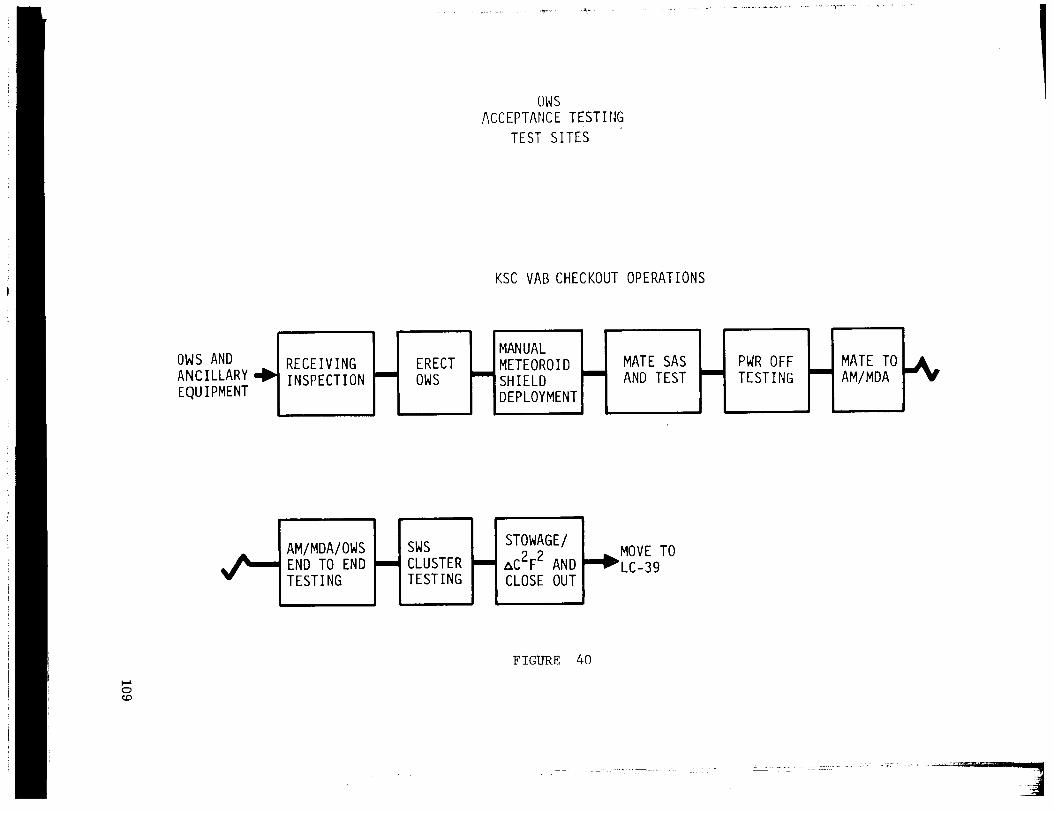
ows
ACCEPTANCE TESTIIJG TEST SITES '
KSC VAB CHECKOUT OPERATIONS
,
OWS AND MANUAL
RECEIVING ERECT METEOROID MATE SAS PWR OFF MATE TO ANC1LLARy+ INSPECTION - OWS - SHIELD - AND TEST - TESTING - AM/MDA EQUIPMENT DEPLOYMENT
FIGURE 40

AIRLOCK MODULE
The airlock module (AM) is the module containing the hatch through which astronauts
egress when performing extravehicular activity (EVA). It also contains systems for
environmental control, instrumentation, electrical power, communications, and opera- r
tional management for the orbiting assembly (OA) or cluster. It is attached to the for-
ward end of the orbital workshop and provides structural support to all modules mounted
forward of the OWS (MDA, ATM, CSM). The AM consists of two concentric cylinders
with truss structures bridging the annular gap. This is illustrated in figures 41 to 44.
The outer cylinder, or the fixed airlock shroud covering the high pressure gas bottles
and encircling the outer AM structure, has the same diameter as the OWS (22 ft). The
inner cylinder, or tunnel, contains the airlock and constitutes the passageway through
which the Skylab crews move between the CSM and MDA on one side to the OWS on the
other. The forward end of the fixed airlock shroud is the base on which the tubular struc-
ture supporting the ATM is mounted.
The airlock itself is the central portion of this module. It has two hatches that close
off each end of the cylinder and a third hatch located in the outer wall that is the EVA
hatch. Closing the two end hatches before opening the EVA hatch ensures that the atmo-
sphere within the rest of the cluster is retained. High pressure gas containers store the
oxygen and nitrogen which provide the internal atmosphere throughout the mission.
The payload shroud, covered in a separate section, fits over the AM as it does over
the MDA and is supported on the fixed airlock shroud.
As with the OWS, the Panel has elected to discuss the AM from two points of view to
better provide an assessment of the adequacy of management systems and their imple-
mentation. Thus, the first portion discusses management systems of the NASA Centers
and McDonnell Douglas Astronautics Company, Eastern Division. The second portion
discusses their implementation as mirrored in the technical aspects of the program.
Management
The basic system of management applied by NASA to the airlock program is similar
to that used on other modules. Variations were necessary however due to the unique
handling of the AM and MDA as a unit during the major phases of testing accomplished at the MDAC-East plant in St. Louis, Missouri. The airlock has more major interfaces
than other modules. Last and certainly not least is the background of the MDAC-East
organization. They have been involved in manned space flight through INO programs prior to Apollo (i. e. , Mercury and Gemini). The basic approach may be the same for
each module contractor, but in the case of MDAC-East the emphasis was placed different-
ly- Furthermore, there was a requirement to use existing hardware where possible. The
110