Communication Systemspkalra/OLD-COURSES/siv864-2010/session-08-11.pdf · Tx Rx. IIT Delhi Nov 6,...
65
IIT Delhi Communication Systems Monika Aggarwal CARE, IIT Delhi
Transcript of Communication Systemspkalra/OLD-COURSES/siv864-2010/session-08-11.pdf · Tx Rx. IIT Delhi Nov 6,...

IIT Delhi
Communication Systems
Monika AggarwalCARE, IIT Delhi

IIT Delhi
2CARE-IITDNov 6, 2008
Communication
� Conveying information.
� Transmission of information,
� Using symbols, signs, behavior, speech, writing, or signals
� Communication is the process of transmitting information from a sender to a
receiver with the use of a medium.
� For us, communication is a process in which the
� Source produces the information
� Transmitter, transmits information
� It is transmitted through a medium
� Receiver receives the transmitted signal
� Received signal reproduces information (may be with some errors).

IIT Delhi
3CARE-IITDNov 6, 2008
Basic Communication
� Communication to transfer information from one point to another.
� Therefore basic constituents of communication system are
� Source
� Medium
� Receiver
Sea Surface
Sea bottom
Tx
Rx

IIT Delhi
4CARE-IITDNov 6, 2008
Basic Blocks of Communication System
Source Transmitter Medium Receiver

IIT Delhi
5CARE-IITDNov 6, 2008
Source
� Source of Signal
� Something we want to transmit!!,
� Data, audio, speech, image, video…
� may be something else also…your feelings!!
� Can be 1-D, 2-D or of any dimension signal.
� Can be of any language.
� Source can be analog or digital.
� Analog signals can also be converted into digital signals before transmitting.

IIT Delhi
6CARE-IITDNov 6, 2008
Source : Information
� What we want to transmit!!,
� something meaningful.
� Meaningful information
� Something new
� Something we do not know
� Redundant information has no value,
� Can be avoided!!
� Information is the measure of meaningful data to be transmitted.

IIT Delhi
7CARE-IITDNov 6, 2008
Information
� Information is acquired through study or experience.
� Measure of the uncertainty of an outcome,
�If you have done bad in exam, than your result has more information.
� Mathematically we define the information as,
�Low probability data has high information
� Information is the measure uncertainty of one unit of signal
)(log)(
1log)( xp
xpxI −==

IIT Delhi
8CARE-IITDNov 6, 2008
Example
� Suppose we have a binary discrete source emits ‘0’ and ‘1’,
� Both ‘0’ and ‘1’ occur with equal probability,
� p(0)=0.5
� p(1)=0.5
� It emits each bit after ts second.
� Information content in the source is
I(x=0) = -log(0.5) = 1
I(x=1) = -log(0.5) = 1
Source is emitting 1 bit of information per ts second.

IIT Delhi
9CARE-IITDNov 6, 2008
Example
� Suppose we have a binary discrete source emits ‘0’ and ‘1’,
� Both ‘0’ and ‘1’ occur with different probability,
� p(0)=q
� p(1)=1-q
� It emits each bit after ts second.
� Information content in the source is
I(x=0) = -log(q) ; I(x=1) = -log(1-q)
� Now how do we calculate the number of bits source is emitting in ts second.
� Take the average of both the outputs
= -q log(q) - (1-q) log(1-q)
� This is entropy of the source
IIT Delhi
10CARE-IITDNov 6, 2008
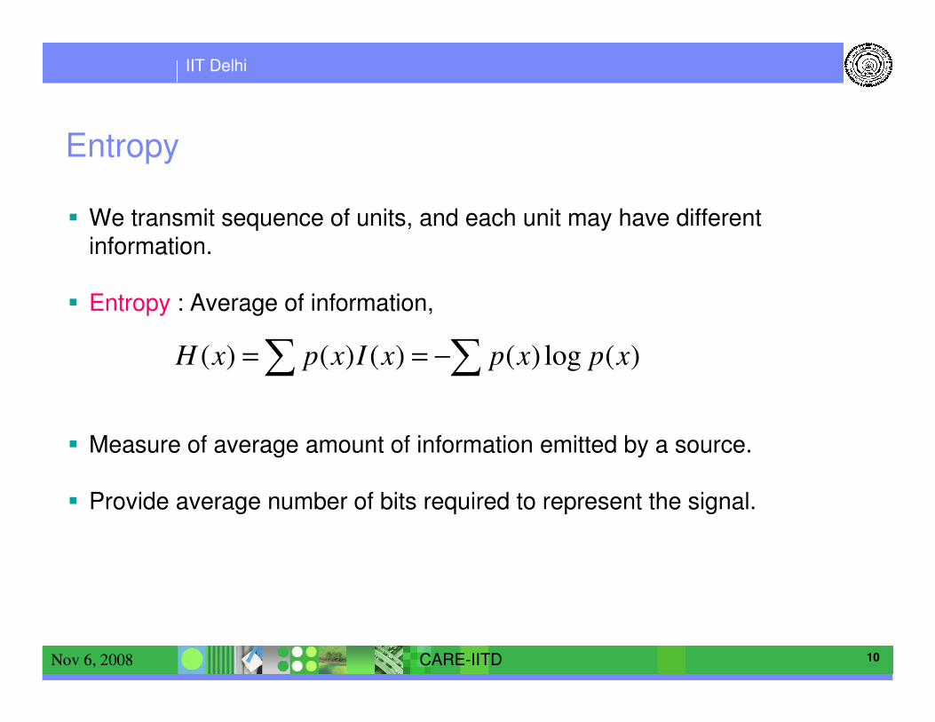
Entropy
� We transmit sequence of units, and each unit may have different information.
� Entropy : Average of information,
� Measure of average amount of information emitted by a source.
� Provide average number of bits required to represent the signal.
∑∑ −== )(log)()()()( xpxpxIxpxH

IIT Delhi
11CARE-IITDNov 6, 2008
Example
� Suppose we have a binary discrete source emits ‘0’ and ‘1’,
� Both ‘0’ and ‘1’ occur with different probability,
� p(0)=q
� p(1)=1-q
� It emits each bit after ts second.
� Entropy the source is
H(x)= -q log(q) - (1-q) log(1-q)
� It is the number of bits source is emitting in ts second
� Source is having information of worth these number of bits

IIT Delhi
12CARE-IITDNov 6, 2008
Entropy and Source Coding
� Entropy gives the minimum number of average bits required to represent the
source.
� Source coding is representing the source outputs by series of bits.
� Both discrete as well as analog signal is to be converted into bits.
� Average of number of bits (R) required represent source output is lower bounded
by source entropy (H(x)).
� Source coding is said to be efficient, if average of number of bits required is equal
to source entropy.

IIT Delhi
13CARE-IITDNov 6, 2008
Source Coding
� Aim of the Source Coding is to represent source signal into bits.
� Codes should be
� Uniquely decodable
� Instantaneously decodable
� Input sequence is 001001
• Code I breaks
• Code III adds delay
• Code II is okay

IIT Delhi
14CARE-IITDNov 6, 2008
Methods of source coding
� Discrete signal
� Probability of block decoding error can be made arbitrary small if
R > H(x).
� examples
• Huffman coding
• Lempel-Ziv Algorithm etc.

IIT Delhi
15CARE-IITDNov 6, 2008
Source Coding : Signal Compression
� Codes should be “uniquely decodable”, i.e. source coding is reversible
� Completely reversible : Lossless coding.
� Partial reversible : Lossy coding
� Analog Signal take can any value
� f : Real --- > Real
� While representing the analog signal into bits, we will always have some loss,
� This loss is measured in terms of distortion ‘D’.
� Distortion is function of number of bits R required to represent the signal or vice versa.

IIT Delhi
16CARE-IITDNov 6, 2008
Some Analog Source Encoding Techniques
� Temporal waveform coding
� Pulse code modulation (PCM)
� Differential Pulse Code Modulation (DPCM)
� Delta Modulation (DM)
� Spectral waveform coding
� Sub-band Coding
� Model based waveform coding
� Linear predictive coding (LPC)

IIT Delhi
17CARE-IITDNov 6, 2008
Some Results of Analog Source encoding

IIT Delhi
18CARE-IITDNov 6, 2008
SinkSource
Decoding
Error
Control/
Channel
Decoding
Demod-
ulation
Receiver
/
Filter
Channel
SourceSource
Coding
Error
Control/
Channel
Coding
Modulation
Transmitter
/
Filter
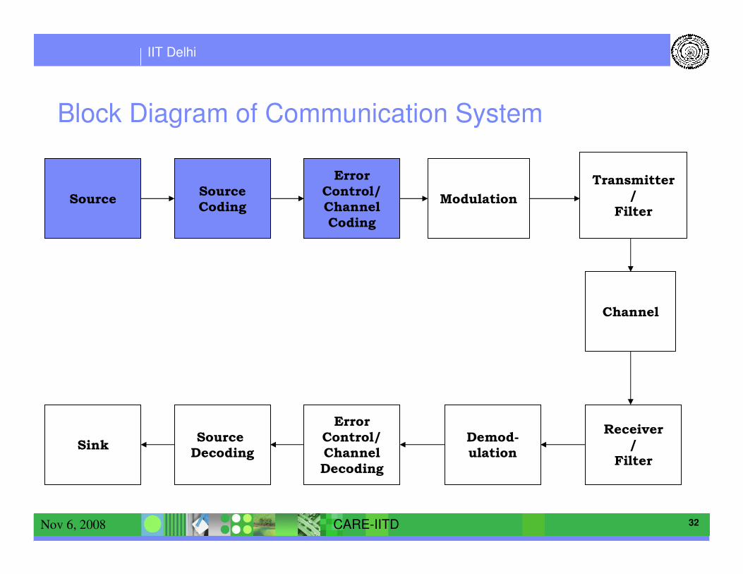
Block Diagram of Communication System
IIT Delhi
19CARE-IITDNov 6, 2008
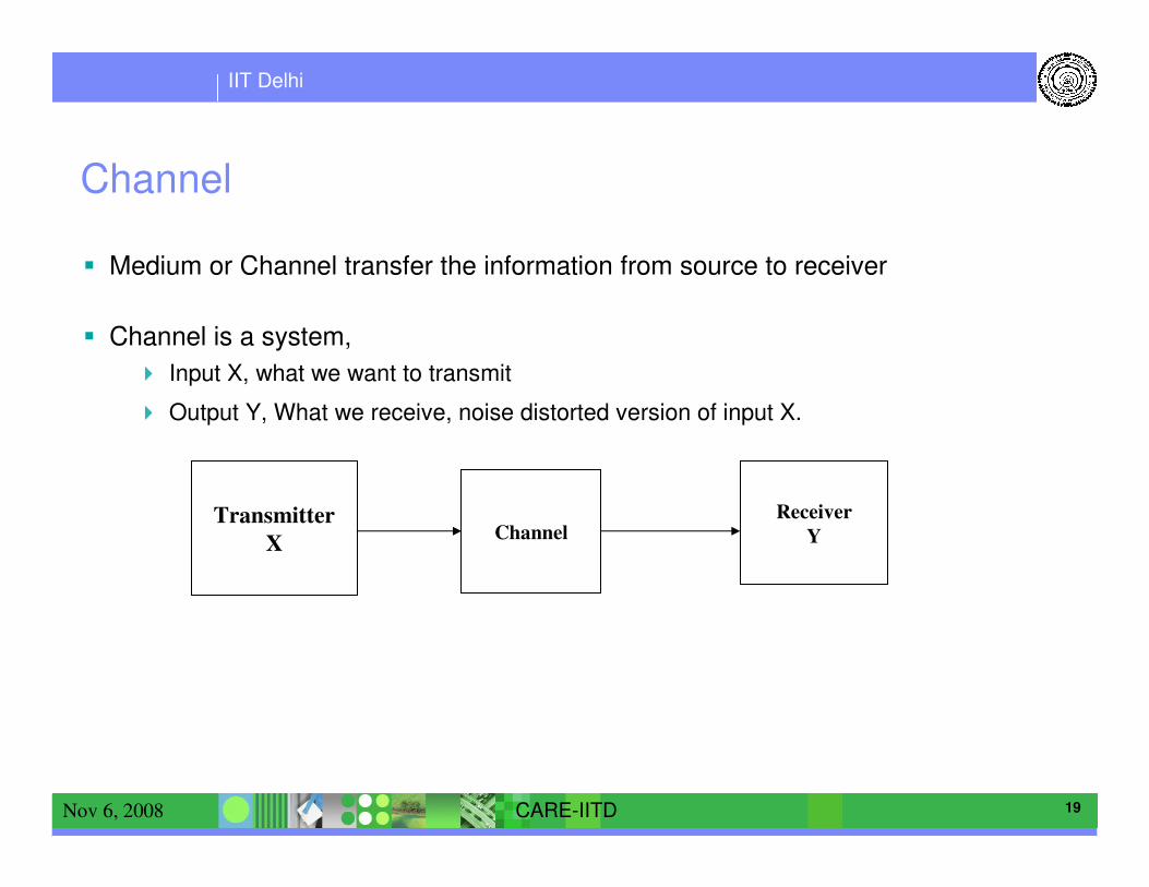
Channel
� Medium or Channel transfer the information from source to receiver
� Channel is a system,
� Input X, what we want to transmit
� Output Y, What we receive, noise distorted version of input X.
Receiver
YChannelTransmitter
X

IIT Delhi
20CARE-IITDNov 6, 2008
Effects of Channel
� Channel effects the communication System in many ways
� It limits its Rate of tranmission
� It adds noise in the transmitted Signal
� It adds distortion in terms of multipath

IIT Delhi
21CARE-IITDNov 6, 2008
Mutual Information
� Aim here is to extract X from received Y.
� Amount of information about X present in Y is very important.
� Because receiver extract X from Y
� This quantity is measured by I(X,Y)
� The average amount of information about X that can be provided by Y
� Average Information present in X is H(X).
� Average amount of information remaining in X, cannot be transferred to Y is
H(X/Y), called conditional entropy.
� So the information of X present in Y is
I(X,Y)=H(X)-H(X/Y)

IIT Delhi
22CARE-IITDNov 6, 2008
Binary Symmetric Channel
� Suppose we have a binary discrete source emits ‘0’ and ‘1’, with probabilities,
� p(X=0) = q
� p(X=1) = 1-q
� Channel conditional probabilities are
� p(Y=0/X=0) = 1-p p(Y=1/X=0) = p
� p(Y=0/X=1) = p p(Y=1/X=1) = 1-p

IIT Delhi
23CARE-IITDNov 6, 2008
Capacity
� I(X,Y) is called mutual information.
� Mutual information is function of the information of signal as well as channel.
� For a given channel, the maximum value of mutual information is measure of the
Capacity of the Channel.

IIT Delhi
24CARE-IITDNov 6, 2008
Binary Symmetric Channel
� Suppose we have a binary discrete source emits ‘0’ and ‘1’, with probabilities,
� p(X=0) = 0.5
� p(X=1) = 0.5
� Channel conditional probabilities are
� p(Y=0/X=0) = 1-p p(Y=1/X=0) = p
� p(Y=0/X=1) = p p(Y=1/X=1) = 1-p

IIT Delhi
25CARE-IITDNov 6, 2008
Rate & Capacity
� For a given channel and given X, we have a certain value of I(X,Y),
� information being transmitted through the channel.
� I(X,Y) per second, information bits transmitted per second is known as Rate R.
� Shannon defined Capacity of channel as the maximum information it can transfer
in unity time.
� For a given Channel, there exists some X for which I(X,Y) is maximum, i.e.
� I(X,Y)=C
� For other X, I(X,Y) will be less than C.
� I(X,Y)<C
� Therefore the maximum value R can take is C.

IIT Delhi
26CARE-IITDNov 6, 2008
Shannon Theorem
� The capacity of a channel is given by
where I(X,Y) is the mutual information between the channel input X and the
output Y. If the transmission rate R is less than C, then for any ε>0 there exists a
code with block length n large enough whose error probability is less than ε. If
R>C, the error probability of any code with any block length is bounded away from
zero.
),(1
maxlim)(
YXITxp
CT ∞>−
=

IIT Delhi
27CARE-IITDNov 6, 2008
Channel Behavior
CHANNELTransmitter Receiver

IIT Delhi
28CARE-IITDNov 6, 2008
Sea Surface
Sea bottom
Tx
Rx
Channel Behavior

IIT Delhi
29CARE-IITDNov 6, 2008
� Channel distorts the signal received at receiver.
� distort /corrupt the information
� At receiver we want to remove the distortion and noise
� Because we want to estimate X from Y.
� As we are only concerned with the information that we have transferred,
� Information represents the complete source output
� We are interested in extracting information about X from Y.
� Receiver will be designed so as to extract the information
� in best possible way,
� in efficient way.
� And should extract maximum information.

IIT Delhi
30CARE-IITDNov 6, 2008
Channel Coding
� Can we do something with the transmitted bits to minimize this corruption.
� The encoder bits (transmitted signals) are modified
� to protect the information from corruption.
� The protection depends upon channel,
� but still we have certain general protection
� You wear sweater, when it is cold etc.
� Adding this protection is called Channel coding.
� We add redundant bits in some particular manner.

IIT Delhi
31CARE-IITDNov 6, 2008
Channel Codes
� Parity bit
� Hamming code
� Convolution codes
� Erasure codes
� Golay code
� BCH codes
� Hadamard code
� Reed-Muller code etc.
IIT Delhi
32CARE-IITDNov 6, 2008
SinkSource
Decoding
Error
Control/
Channel
Decoding
Demod-
ulation
Receiver
/
Filter
Channel
SourceSource
Coding
Error
Control/
Channel
Coding
Modulation
Transmitter
/
Filter
Block Diagram of Communication System

IIT Delhi
33CARE-IITDNov 6, 2008
Summary
� By Source coding we have compressed the signal as much as possible.
� By adjusting the rate we know that error free communication is possible
� By channel coding we have added the protection to the signal.
� Now we want to transmit the signal,
� It will physically be transmitted

IIT Delhi
34CARE-IITDNov 6, 2008
Modulation
� Information signal is generally a low frequency Signal,
� It is difficult to transmit low frequency signals
� we required large height antenna.
� To transmit it over a long distance, we need a carrier.
� Carrier is high frequency signal, which carries the information signal from source to the
receiver.
� Carrier is generally a high frequency sinusoid.
� Carrier frequency depends upon the channel, transducer etc.
� Carrier carriers the information from the source to the transmitter,
� Information can be carried in amplitude of carrier : amplitude modulation
� Frequency of carrier : frequency modulation
� Phase of carrier : phase modulation

IIT Delhi
35CARE-IITDNov 6, 2008

IIT Delhi
36CARE-IITDNov 6, 2008
Digital Communication
� When the information transmitted is in the form of bits we have digital
communication.
� Amplitude modulation � Amplitude shift keying
� Frequency Modulation�Frquency shift keying
� Phase modulation� Phase shift keying

IIT Delhi
37CARE-IITDNov 6, 2008

IIT Delhi
38CARE-IITDNov 6, 2008
Analog vs. Digital Communication
� Analog communication uses continuous-time signals that
� Can (in principle) take any real value
� When received, produce an output that also varies continuously
� Digital communication uses continuous-time signals that:
� Represent bits or bit groups using a finite, standard alphabet
� Continuous-time inputs are sampled, giving discrete-time series that are digitized and
encoded before being transmitted
� Can be “cleaned up” from some distortion and noise, but generally do
� Digital is profoundly different from analog

IIT Delhi
39CARE-IITDNov 6, 2008
Why Digital Communication
� Digital encoding uses a finite alphabet to represent bits or bit groups.
� The transmitted alphabet has to be a member of this finite set.
� Therefore when receiver receives the corrupted signal, it can be corrected to the
nearest possible member of the set.
� Distortion and noise don’t matter, as long as each digital waveform can be
recognized and distinguished from a small set of other waveforms
� Digital communication changes the paradigm from waveform replication to
waveform recognition.
� Digital techniques greatly reduce the effects of noise and distortion, and make it
possible to approach theoretical information-capacity limits

IIT Delhi
40CARE-IITDNov 6, 2008
Phase Shift Keying
� Phase of the carrier is varied with the information bits.
� Information bits are mapped to a finite set of alphabets.
� Each alphabet gives a corresponding phase shift to carrier.
� E.g. Let us assume that the information bits are mapped to set of 4 alphabets
(M=4).
� Two bits together will form one alphabet.
� Let us assume that the elements of the sets are {A,B,C,D}
• 00�A�phase change of ‘0’ degree
• 01�B�phase change of ‘90’ degree
• 10�C�phase change of ‘180’ degree
• 11�D�phase change of ‘270’ degree

IIT Delhi
41CARE-IITDNov 6, 2008
Example
� Input bits are
� input bits {1 0 1 1 0 1 1 1 0 0 0 1 1 0 0 1 1 1 }
� Alphabates {C D B D A B C B D }
� Phase changes{180 270 90 270 0 90 270 90 270}
00�A�phase change of ‘0’ degree
01�B�phase change of ‘90’ degree
10�C�phase change of ‘180’ degree
11�D�phase change of ‘270’ degree
0 2 4 6 8 1 0 1 2 1 4 1 6 1 8 2 0 2 2- 3
- 2
- 1
0
1
2
3

IIT Delhi
42CARE-IITDNov 6, 2008

IIT Delhi
43CARE-IITDNov 6, 2008
PSK modulation
)_2
2cos()()( alphabetinputM
tftatx c
ππ +=
input bits {1 0 1 1 0 1 1 1 0 0 0 1 1 0 0 1 1 1 }
Alphabates {C D B D A B C B D }
Alphabates {2 3 1 3 0 1 2 1 3 }
Phase changes{180 270 90 270 0 90 270 90 270}
Phase change Alphabates *2 π/4

IIT Delhi
44CARE-IITDNov 6, 2008
PSK Constellation
A, 00
B, 01
C, 10
D, 11

IIT Delhi
45CARE-IITDNov 6, 2008
De-Modulation
� Demodulation is the processes of removing the carrier from the transmitted signal.
� Estimate the change in the corresponding quantity of the carrier.
� Estimate the change in corresponding amplitude, frequency or phase…
� In Digital Communication, as we had finite alphabet set, the corresponding
change can be corrected to possible value
• replication to recognition.!!
� PSK modulation, estimate the change in the phase,
� Approximate it to the allowed values of phase change
� De-map phase change � alphabet� information bits.

IIT Delhi
46CARE-IITDNov 6, 2008

IIT Delhi
47CARE-IITDNov 6, 2008

IIT Delhi
48CARE-IITDNov 6, 2008
Receiver Chain
� Detect the incoming signal
� Differentiate from noise.
� Adjust the amplitude of receiving Signal : Automatic Gain Controller
� Most Important in AM
� Remove the Channel multi-path effect : Equalizer
� Synchronize the Clock of Receiver to transmitter
� Carrier Synchronization
• Moving platform can add Doppler and change the carrier frequency
� Timing Synchronization
� Undo the What we have done knowingly at the transmitter
� Channel Decoder
� Source Decoder

IIT Delhi
49CARE-IITDNov 6, 2008
Channel Equalization
CHANNELEQUA-
LIZER

IIT Delhi
50CARE-IITDNov 6, 2008
Performance
� Bit error Rate vs. SNR

IIT Delhi
51CARE-IITDNov 6, 2008

IIT Delhi
52CARE-IITDNov 6, 2008
SinkSource
Decoding
Error
Control/
Channel
Decoding
Demod-
ulation
Receiver
/
Filter
Channel
SourceSource
Coding
Error
Control/
Channel
Coding
Modulation
Transmitter
/
Filter
Block Diagram of Communication System
Modulation
Transmitter
/
Filter
Channel
Receiver
{AGC,
Detector
Equalizer
Synchronizer}
Demod-
ulation
Error
Control/
Channel
Decoding
Source
DecodingSink

IIT Delhi
53CARE-IITDNov 6, 2008
MIMO Communication

IIT Delhi
54CARE-IITDNov 6, 2008
MIMO Systems
Multiple transmitters and multiple receivers are used simultaneously
to increase rate, range etc. of communication system.
User data streamUser data stream
.
.
1
2
MT
.
.
.
1
2
MR
.
.
.
.
.
channel

IIT Delhi
55CARE-IITDNov 6, 2008
SISO

IIT Delhi
56CARE-IITDNov 6, 2008
MIMO

IIT Delhi
57CARE-IITDNov 6, 2008
Error Rate in Fading Channel
An Observation
For the Fading channel
QPSK and other
schemes (designed for
AWGN channel) results
into degradation in
probability of error.

IIT Delhi
58CARE-IITDNov 6, 2008
Bandwidth requirement and range of a 1 Gb/s link using MIMO technology

IIT Delhi
59CARE-IITDNov 6, 2008
Classical receive diversityClassical receive diversity
H11
H21
+=
*
22 HHIdetlogt
T
nσ
PC
Capacity increases logarithmically
with number of receive antennas...
=
21
11H
H
H

IIT Delhi
60CARE-IITDNov 6, 2008
Multiple Input Multiple Output systemsMultiple Input Multiple Output systems
H11
H22
H12
H21
=
2221
1211
HH
HHH
IIT Delhi
61CARE-IITDNov 6, 2008
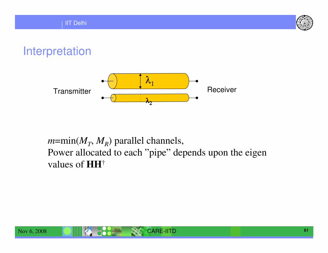
Interpretation
λ1
λλλλ2222
m=min(MT, MR) parallel channels,
Power allocated to each ”pipe” depends upon the eigen
values of HH†
ReceiverTransmitter

IIT Delhi
62CARE-IITDNov 6, 2008
Other Communication Techniques :OFDM
� Orthogonal frequency-division multiplexing (OFDM) is a method of digital
modulation in which a signal is split into several narrowband channels at different
frequencies.
� OFDM is combination of modulation and multiplexing
� Parallel channel transmission so that the effective data rate of each channel is low – multi-carrier modulation

IIT Delhi
63CARE-IITDNov 6, 2008
Ch.1
Ch.2 Ch.3 Ch.4 Ch.5 Ch.6 Ch.7 Ch.8 Ch.9 Ch.10
Saving of bandwidth
Ch.3 Ch.5 Ch.7 Ch.9Ch.2 Ch.4 Ch.6 Ch.8 Ch.10
Ch.1
Conventional multicarrier techniques
50% bandwidth saving
frequency

IIT Delhi
64CARE-IITDNov 6, 2008
CDMA
� Code division multiple access (CDMA), is a spread spectrum multiple access
technique

IIT Delhi
65CARE-IITDNov 6, 2008
Conclusions
� We studied the basic of Communication systems
� Overview of the advances in communication Technology.
Thank You!Thank You!Thank You!Thank You!