Model TLD339A37 Triaxial ICP® Accelerometer Installation ...

ADCP-75-010Rev B, May 2018commscope.com
CommScope ProAx® Triaxial Camera Connectors
InstallationInstructions
Content Page
INTRODUCTION . . . . . . . . . . . . . . . . . . . . . . . . . . . . . . . . . . . . . . . . . . . . . . . . . . . . . . . . . . . . . . . . . . . . . . . . . . . . . 1
1 GENERAL INFORMATION . . . . . . . . . . . . . . . . . . . . . . . . . . . . . . . . . . . . . . . . . . . . . . . . . . . . . . . . . . . . . . . . . . 2
1.1 Standard Tools . . . . . . . . . . . . . . . . . . . . . . . . . . . . . . . . . . . . . . . . . . . . . . . . . . . . . . . . . . . . . . . . . . . 2
1.2 CommScope ProAx Triaxial Cable Strip Gauge . . . . . . . . . . . . . . . . . . . . . . . . . . . . . . . . . . . . . . . . . . . . . 3
1.3 ProAx Triaxial Connector Components . . . . . . . . . . . . . . . . . . . . . . . . . . . . . . . . . . . . . . . . . . . . . . . . . . . 4
2 ASSEMBLY PROCEDURE FOR PROAX TRIAXIAL CONNECTOR JACK AND PLUG . . . . . . . . . . . . . . . . . . . . . . . . . . . . . 5
3 REPAIRING U.S. STANDARD CONNECTOR USING GLOBAL REPAIR KIT. . . . . . . . . . . . . . . . . . . . . . . . . . . . . . . . . . 13
4 CONTACT INFORMATION . . . . . . . . . . . . . . . . . . . . . . . . . . . . . . . . . . . . . . . . . . . . . . . . . . . . . . . . . . . . . . . . . 14
INTRODUCTION
This manual provides procedures for installing CommScope ProAx Triaxial Camera Connectors on coaxial cables.
Because assembly of ProAx triaxial connectors differ from the assembly of other triaxial connectors, it is very important that this procedure be closely followed.
Revision History
ISSUE DATE REASON FOR CHANGE
1 1/2002 Original.
2 7/2004 Add dual dimensions and remove Global references.
3 2/2009 Add US standard front shell.
Rev B May 2018 Updated to CommScope format.
Trademark Information
CommScope and ProAx are registered trademarks of CommScope, Inc.
ADCP-75-010 Rev B Page 1© 2018, CommScope, Inc.

ADCP-75-010 • Rev B • May 2018
1 GENERAL INFORMATION
CommScope ProAx Triaxial Camera Connectors may be used to mate any two triax cables together, cables need not be from the same manufacturer. Once a cable is terminated with a back shell it can easily be converted to mate with any other triax connector standard by adding the appropriate front center conductor shell assembly, outer insulator, and front connector body. CommScope offers connector components (front center conductor shell assembly, outer insulator, and front connector body) to match most standard connectors in the industry (Kings, Fischer, Lemo, etc.).
Use this procedure to ensure correct assembly and reliable operation of ProAx triaxial connectors. This connector assembly procedure is intended to be used for assembling all sizes of female ProAx triaxial jacks and all sizes of male ProAx triaxial plugs.
Note: Because assembly of the ProAx triaxial connectors is different than the assembly of other manufacturers’ triaxial connectors, please follow this assembly procedure closely.
1.1 Standard Tools
ProAx triaxial connectors are assembled using SAE or metric tools. A measuring tape or ruler and pen or marker are used to measure and mark the amount of cable jacket, dielectric, and braid to cut. Tape, such as plastic electrical tape or masking tape is also used to hold the outer braid in place during the assembly procedure. Required tools are shown in Figure 1.
16827-B
TWO 22mm(7/8-INCH)
OPEN END ORCOMBINATION
WRENCHES
TWO 11 mm(7/16-INCH)
OPEN END ORCOMBINATION
WRENCHES
VOLT/OHMMETER
SIDECUTTERS
KNIFE ORBLADE INHOLDER
CRIMP TOOL WITHAPPROPRIATE
DIE SET
ONE 18mm( 3/4-INCH)
OPEN END ORCOMBINATION
WRENCH
Figure 1. Standard Tools Used for ProAx Triaxial Connector Assembly
Page 2© 2018, CommScope, Inc.

ADCP-75-010 • Rev B • May 2018
1.2 CommScope ProAx Triaxial Cable Strip Gauge
An optional CommScope ProAx triaxial cable strip gauge may be used to measure and hold the cable when cutting cable jacket, dielectric, and braid. An optional CommScope ProAx triaxial cable strip gauge is shown in Figure 2.
To use the optional CommScope ProAx triaxial cable strip gauge in this connector assembly procedure, insert cable into slot in gauge corresponding to the operation to be performed. Insert cable into the end of the slot against the wall in the slot. Then cut the cable jacket, dielectric, or braid at the edge of the gauge, parallel to gauge edge, all around the cable in the order noted.
ProAx
CUTOUTER JACKET
CUTOUTER DIELECTRIC
CUTINNER DIELECTRIC
CUTINNER BRAID
13366-A
Figure 2. CommScope ProAx Triaxial Cable Strip Gauge
Page 3© 2018, CommScope, Inc.

ADCP-75-010 • Rev B • May 2018
1.3 ProAx Triaxial Connector Components
Each ProAx triaxial connector consists of the individual parts shown in Figure 3. Also shipped with the ProAx triaxial connector is an installation drawing. For additional information refer to installation drawing when assembling the connector.
FRONT CENTER CONDUCTOR SHELL ASSEMBLY
FRONTCONNECTOR
BODY
OUTER INSULATOR
BARRELSPACER
REAR CENTERCONDUCTOR SHELL
CENTER CONDUCTOR(MALE) PIN 0.064 INCH (1.63mm)
CRIMPSLEEVE
GROUNDWASHER
THREADED INSERTWITH TWO O-RINGS
TAPEREDLOCKINGDEVICE
REAR SEAL RING(SHIPPED INSIDEREAR END CAP)
O-RING(SHIPPED INSIDEREAR END CAP)
REAREND CAP
16819-C
GLOBAL COMPONENTS
UNIVERSAL COMPONENTS
FRONT CONNECTOR BODY
OUTER CONDUCTORINSULATOR (SHIPPED INSIDEFRONT CONNECTOR BODY)
FRONT CENTER CONDUCTORSHELL ASSEMBLY
THREADEDEND
SPLIT,TAPERED
END
CENTER CONDUCTORPIN (MALE)
REAR CENTERCONDUCTOR
SHELL
CRIMPSLEEVE
SPACER (SHIPPED INSIDEOUTER CONDUCTOR INSULATOR)
U.S. STANDARD COMPONENTS
Figure 3. ProAx Triaxial Connector Components, Male Connector Components Shown
Page 4© 2018, CommScope, Inc.

ADCP-75-010 • Rev B • May 2018
Some parts are partially assembled or are placed within other parts for shipping. Before beginning assembly of ProAx triaxial connector, remove all parts from shipping bags and separate all parts. Unscrew rear end cap from front connector body and remove ground washer and outer conductor insulator from inside of the front connector body. Remove O-ring and rear seal ring from inside the rear end cap.
2 ASSEMBLY PROCEDURE FOR PROAX TRIAXIAL CONNECTOR JACK AND PLUG
Assemble ProAx triaxial connector onto the corresponding size of triaxial cable by performing the following steps:
1. Using a blade (in holder or knife), cut end of cable off as square to the cable as possible. See Figure 4.
2. Slide rear end cap and o-ring onto cable. Slide rear seal ring over cable outer jacket with larger inner diameter (thinner ring wall) facing towards cut end of the cable. See Figure 3 and Figure 4.
CABLE
O-RING
OUTERJACKET
REAREND CAP
REAR SEALRING
LARGERINNER
DIAMETER
19845-A
TAPEREDLOCKINGDEVICE
CUT ENDSQUARE
3. Slide tapered locking device onto cable with the larger outside diameter facing cut end of cable. See Figure 4. Tapered locking device is not used when repairing a U.S. Standard connector.
Figure 4. Rear Seal Ring, O-Ring, and Rear End Cap on Cable
4. Using a blade, cut a 2.62 cm (1-inch) length of outer jacket from the cable (see dimensions in Figure 5). Cut off outer jacket only, evenly around entire cable.
If using the CommScope triaxial cable strip gauge, place end of cable into slot labeled, CUT OUTER JACKET. Push the end of cable against the end of the slot. Cut the outer jacket only, evenly around entire cable, at the edge of the gauge (parallel to the gauge edge).
Note: To prevent outer braid from being cut or nicked, do not cut deeper than outer jackets.
Page 5© 2018, CommScope, Inc.

ADCP-75-010 • Rev B • May 2018
CABLE
O-RING
OUTERJACKETOUTER
BRAID
REAREND CAP
2.62 cm(1.03 IN.)
REAR SEALRING
LARGERINNER
DIAMETER
19846-A
TAPEREDLOCKINGDEVICE
Figure 5. Outer Jacket Cut Dimensions
5. After removing outer jacket, wrap tape around outer braid (shield) to prevent braid from fraying and breaking. See Figure 6.
CABLE
O-RING
OUTERJACKETOUTER
BRAID
REAREND CAP
TAPEEND
REAR SEALRING
LARGERINNER
DIAMETER
19847-A
TAPEREDLOCKINGDEVICE
Figure 6. Tape Braid to Prevent Fraying and Breaking
6. Slide threaded insert (see Figure 3) over tape and outer braid. Push the end of threaded insert against outer dielectric (inner jacket and insulation) until it is seated. See Figure 7.
Note: Do not tighten any parts that are on the cable at this time. This is done later in this procedure.
Page 6© 2018, CommScope, Inc.

ADCP-75-010 • Rev B • May 2018
19848-A
OUTER BRAID
OUTER DIELECTRIC(INNER JACKET)
TAPEREDLOCKINGDEVICE
THREADEDINSERT
O-RING
REAR SEALRING
REAREND CAP
CABLE
TAPE
Figure 7. Threaded Insert Installation
7. Remove tape from cable end. Pull back outer braid and comb it out over threaded insert (see Figure 8).
19849-A
OUTER BRAID(TRIMMED)
OUTER DIELECTRIC(INNER JACKET)
TAPEREDLOCKINGDEVICE
THREADEDINSERT
O-RING
REAR SEALRING
REAREND CAP
CABLE
Figure 8. Outer Braid Trimmed
8. Slide ground washer (see Figure 3) over cable and push it against the braid and over threaded insert (pushing the braid over the threaded insert). See Figure 9.
9. Using a side cutters, trim excess braid so that braid extends just beyond the lip (raised edge next to O-ring) of the threaded insert. See Figure 8 and Figure 9.
Page 7© 2018, CommScope, Inc.

ADCP-75-010 • Rev B • May 2018
16822-D
RAISEDEDGE
THREADEDINSERT
REAR SEALRING
O-RING
OUTER BRAID(TRIMMED)
TAPEREDLOCKINGDEVICE
REAREND CAP
OUTERDIELECTRIC
GROUND WASHER(SHIPPED INSIDE FRONT
CONNECTOR BODY)
Figure 9. Cable with Outer Braid Over Threaded Insert, After Trimming
10. Using a blade, remove outer dielectric (inner jacket and insulation) so that the length from the end of cable to the end of the outer dielectric is 1.51 cm (0.59-inch). See dimensions in Figure 10. Cut outer dielectric only, evenly around entire cable.
If using the CommScope ProAx triaxial cable gauge, place end of the cable into slot labeled, CUT OUTER DIELECTRIC. Push end of cable against the end of the slot. Cut outer dielectric only, evenly around entire cable, at the edge of the gauge.
Note: Be careful to not cut or nick the inner braid.
19850-A
0.32 cm(0.13 IN.)
0.79 cm(0.31 IN.)
1.51 cm(0.59 IN.)
CABLE CENTERCONDUCTOR
INNERBRAID
INNERDIELECTRIC
OUTER DIELECTRIC(INNER JACKET)
TAPEREDLOCKINGDEVICE
THREADEDINSERT
O-RING
REAR SEALRING
REAREND CAP
CABLEGROUNDWASHER
Figure 10. Inner Braid, and Inner Dielectric Cut Dimensions
Page 8© 2018, CommScope, Inc.

ADCP-75-010 • Rev B • May 2018
11. Using a blade, remove inner braid so that the length from the end of cable to the end of inner braid is 0.79 cm (0.31-inch). See dimensions in Figure 10. Evenly cut inner braid only, around entire cable.
If using the CommScope ProAx triaxial cable gauge, place end of cable into slot labeled, CUT INNER BRAID. Push end of cable against the end of the slot. Cut inner braid only, evenly around entire cable, at the edge of the gauge.
Note: Be careful to not cut or nick the inner dielectric under the braid.
12. Using a blade, remove inner dielectric so that the length from the end of cable to the end of inner dielectric is 0.32 cm (0.13-inch) See dimensions in Figure 10. Evenly cut inner dielectric only, around entire cable.
If using the CommScope triaxial cable gauge, place end of cable into slot labeled, CUT INNER DIELECTRIC. Push end of cable against the end of the slot. Evenly cut inner dielectric only, around entire cable, at the edge of the gauge.
Note: Be careful to not cut or nick the center conductor under the inner dielectric.
13. Slide a center conductor pin (see Figure 3) over the center conductor of cable, against inner dielectric. See Figure 11.
Note: Be sure that center conductor pin is fully seated against inner dielectric and that cable center conductor is visible through inspection hole in the center pin (see Figure 11).Note: If using stranded center conductor cable make certain all of the strands are inserted inside the center conductor pin. Do not trim away any that are on the outside, if necessary twist the stranded conductor together before sliding it into the center conductor pin.
THREADEDEND
KNURLEDEND
16823-B
CENTERSECTION
CENTERCONDUCTORINSULATOR
THREADEDINSIDE
FRONT CENTERCONDUCTOR SHELL
REAR CENTERCONDUCTOR
SHELL
MALE CENTERCONDUCTOR PIN
CRIMPED ON CABLECENTER CONDUCTOR
CRIMPSLEEVE
INNERBRAID
GROUNDWASHER OVEROUTER BRAID
INSPECTIONHOLE
OUTER DIELECTRIC(INNER JACKET)
THREADEDINSERT
TAPEREDLOCKINGDEVICE
Figure 11. Ground Washer Over Outer Braid, Center Conductor Pin Crimped on Cable Center Conductor
Page 9© 2018, CommScope, Inc.

ADCP-75-010 • Rev B • May 2018
14. Using the 1.73 mm (0.068 in.) center pin die in crimp tool, align and crimp center conductor pin onto the cable center conductor. One side of for right handed people the other side is for left handed people. This connection may also be made using solder.
15. Slide a crimp sleeve (see Figure 3) over inner braid and outer dielectric, up against the ground washer. See Figure 11.
16. Loosen and spread out inner braid.
17. Slide knurled end of rear center conductor shell inside crimp sleeve (pushing inner braid inward between rear center conductor shell and crimp sleeve), twisting the rear center conductor shell as it is inserted.
Ensure that inner braid is evenly distributed between rear center conductor shell and crimp sleeve. Make certain that crimp sleeve is against raised center section of conductor shell.
Adjust position of rear center conductor shell and crimp sleeve on cable so that center conductor pin is approximately flush with the threaded end of rear center conductor shell and is centered in conductor shell. See Figure 12.
Verify that outer dielectric is visible between crimp sleeve and ground washer (see Figure 11 and Figure 12).
16824-C
THREADEDINSERT
REAREND CAP
GROUND WASHEROVER TRIMMEDOUTER BRAID
OUTERDIELECTRIC
VISIBLE
CRIMP SLEEVE(BEFORE CRIMPING)
REAR CENTERCONDUCTOR SHELL
(KNURLED ENDUNDER CRIMP SLEEVE)
THREADEDEND
CENTER CONDUCTOR PINCENTERED AND APPROX.FLUSH WITH THREADEDEND OF REAR CENTER
CONDUCTOR SHELL
Figure 12. Rear Center Conductor Shell and Crimp Sleeve Assembled with Outer Dielectric Visible
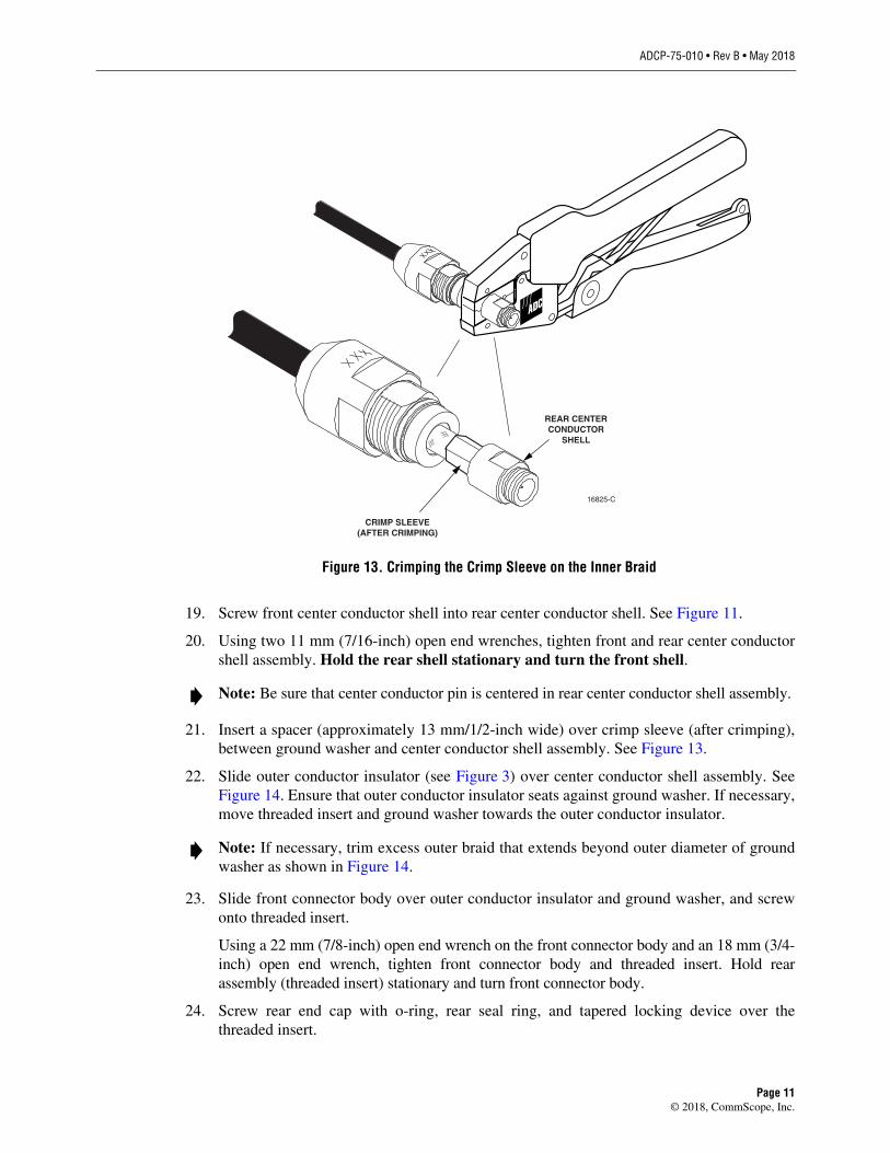
18. Using the larger die in crimp tool, crimp around the crimp sleeve See Figure 13.
Page 10© 2018, CommScope, Inc.
ADCP-75-010 • Rev B • May 2018
16825-C
REAR CENTERCONDUCTOR
SHELL
CRIMP SLEEVE(AFTER CRIMPING)
Figure 13. Crimping the Crimp Sleeve on the Inner Braid
19. Screw front center conductor shell into rear center conductor shell. See Figure 11.
20. Using two 11 mm (7/16-inch) open end wrenches, tighten front and rear center conductor shell assembly. Hold the rear shell stationary and turn the front shell.
Note: Be sure that center conductor pin is centered in rear center conductor shell assembly.
21. Insert a spacer (approximately 13 mm/1/2-inch wide) over crimp sleeve (after crimping), between ground washer and center conductor shell assembly. See Figure 13.
22. Slide outer conductor insulator (see Figure 3) over center conductor shell assembly. See Figure 14. Ensure that outer conductor insulator seats against ground washer. If necessary, move threaded insert and ground washer towards the outer conductor insulator.
Note: If necessary, trim excess outer braid that extends beyond outer diameter of ground washer as shown in Figure 14.
23. Slide front connector body over outer conductor insulator and ground washer, and screw onto threaded insert.
Using a 22 mm (7/8-inch) open end wrench on the front connector body and an 18 mm (3/4-inch) open end wrench, tighten front connector body and threaded insert. Hold rear assembly (threaded insert) stationary and turn front connector body.
24. Screw rear end cap with o-ring, rear seal ring, and tapered locking device over the threaded insert.
Page 11© 2018, CommScope, Inc.

ADCP-75-010 • Rev B • May 2018
FRONTCONNECTOR
BODYOUTER
CONDUCTORINSULATOR CENTER CONDUCTOR
SHELL ASSEMBLY
OUTER BRAID(TRIMMED) REAR SEAL
RING REAREND CAP
CRIMPEDSLEEVE
CABLEOUTER
DIELECTRIC
GROUNDWASHER
TAPEREDLOCKINGDEVICE
THREADEDINSERT O-RING
CABLE
16826-C
SPACER INSERTEDAFTER CRIMPING
*NOTE: SPACER (APPROXIMATELY 1/8 INCH WIDE, SHOWN), USED WITH CONNECTOR FOR 1/2-INCH "C" CABLE, FITS OVER THE OUTER DIELECTRIC, BETWEEN GROUND WASHER AND CRIMP SLEEVE. SPACER (APPROXIMATELY 1/2 INCH WIDE, SHOWN IN FIGURE 3), USED WITH CONNECTORS FOR OTHER SIZE CABLES, FITS OVER CRIMP SLEEVE (AFTER CRIMPING), BETWEEN GROUND WASHER AND REAR CENTER CONDUCTOR SHELL.
FRONTCONNECTOR
BODYOUTER
CONDUCTORINSULATOROUTE CENTER CONDUCTOR
SHELL ASSEMBLY
CRIMPEDSLEEVE
CABLEOUTER
DIELECTRIC
*SPACER INSERTEDAFTER CRIMPING
OR
GLOBAL COMPONENTS
U. S. STANDARD COMPONENTS
UNIVERSAL COMPONENTS
Figure 14. Connector Assembly, Showing Spacer and Outer Conductor Insulator Location
Page 12© 2018, CommScope, Inc.

ADCP-75-010 • Rev B • May 2018
25. Using two 22 mm (7/8-inch) open end wrenches tighten rear end cap, threaded insert, and front body connector. Hold front assembly stationary and turn rear end cap.
Note: Tighten rear end cap until the two assemblies are fully seated together.
26. Using an ohmmeter, measure between each braid and measure between each braid and the center conductor for infinite resistance, assuring no short circuits between any conductors. Measure end to end continuity (low resistance) on all three conductors.
3 REPAIRING U.S. STANDARD CONNECTOR USING GLOBAL REPAIR KIT
Global connector center conductor repair kits are now used to repair both Global and U.S. standard center conductors. When repairing a U.S. standard connector the Tapered Locking Device, see Figure 14 is not used. Follow the Assembly Procedure for PROAX Triaxial Connector Jack and Plug on page 5 to complete the center conductor repair.
Page 13© 2018, CommScope, Inc.

ADCP-75-010 • Rev B • May 2018
4 CONTACT INFORMATION
To find out more about CommScope® products, visit us on the web athttp://www.commscope.com
For technical assistance, customer service, or to report any missing/damaged parts, visit us at http://www.commscope.com/SupportCenter
Page 14