
Commonwealth Air Training Plan Museum Volume 39 No. 3
9
Commonwealth Air Training Plan Museum Volume 39 No. 3 Summer 2020
Transcript of Commonwealth Air Training Plan Museum Volume 39 No. 3

Commonwealth Air
Training Plan Museum
Volume 39 No. 3
Summer 2020
The Commonwealth Air Training Museum
McGill Field, Brandon Airport
Box 3 Group 520 RR 5
Brandon, Manitoba R7A 5Y5
Email - [email protected]
Web Page – http://www.airmuseum.ca/
President - John McNarry
Vice President - John Robinson
Past President - Jeff Harwood
Treasurer - Judith Grierson
Secretary - Barb Henderson
Executive Director - Stephen Hayter
Administrative Assistant - Kathryn Sheppard
Directors
David Jenkins, Angus Sneesby,
Greg Sigurdson,
Mark Odegard, Peter Moodie
Committee Managers
Bricks and Mortar - Gerry Kemp
Flying Committee – Mark Odegard
Adjutant - Judith Grierson
Fairey Battle - David Jenkins
Lysander – Jack Leonard
Ladies’ Auxiliary – Marion Decosse
Archives - Greg Sigurdson
CONTACT Editor - Greg Sigurdson
Front Desk –
Museum Shop - Jan McNarry
Darkroom - Lyle Gawletz
Motor Transport - John McNarry, Grant Shaw
Security - John Robinson
Webmaster – Bill Hillman
Foundation
Judith Grierson, Jeff Harwood,
Dave Shuttleworth, Clarence Davis,
Elaine Chisholm
CONTACT Volume 39 Issue 3
Summer 2020 Our Cover – a drawing of a four-engine aircraft flying over a
Link Trainer. The significance is this early flight simulator
created Allied pilots with superior flying skills which helped the
Allied countries win the war. This issue is devoted to the Link
Trainer, in two parts – one exploring the history of the Link and
experiences fledging pilots endured while spending hours and
hours learning to fly it, The second part is a semi-technical
explanation of how Links work and courses that were offered in
training. We hope you find this interesting and relevant to the
purpose of our museum.
On August 27 2020 I had the pleasure of
watching an online power point presentation about the
Link Trainer as sponsored by the Canadian Aviation
Historical Society, Manitoba chapter. It was a well put-
together presentation with lots of interesting information
about the trainer and its inventor, Edwin Link.
Created by the CAHS National Membership
Secretary and retired Royal Canadian Air Force member
John Chalmers, his talk showed a superior knowledge of
the trainer and broader knowledge of the RCAF in World
War II as well as the current positive state of historical
efforts to remember and preserve the story of the British
Commonwealth Air Training Plan.
We at the Commonwealth Air Training Museum have much to be thankful for despite the financial beating the Covid-19 Pandemic has laid. We, like most other historical organization, have had a difficult six months due to our losses in visitor admissions and rental revenue from the Canteen. Despite loosing this vital money for operating costs, all is not lost. Even with reduced income, we wo;; cover a good portion of our expenses with the income we receive along with savings accumulated over the years. We have had great financial support from the provincial and federal governments. Modifications to the Manitoba Signature Museum program have given us a sizable endowment which should help support us for decades to come. Thank-you Province of Manitoba. We also accessed significant funding from the new federal programs initiated in the last few months. Thank you Government of Canada in assisting us to make up our shortfall in income this year. We must also thank all of our active volunteers for seriously taking the request to cut back spending in all departments and projects for the foreseeable future. Their efforts have greatly eased the burden on operating and project expenses. Now, a message for our loyal members and friends. You have always been there with great financial aid over the years. Please keep up this fine support by responding to our upcoming request for funds. Please give again, and think about increasing the size of the donation while we are under these current difficult circumstances. If you are a regular member, please renew your membership for 2020 at the end of this year and consider sending a small donation along with your fees. Once again, thank you for your generous and incredible help over the years – financial or otherwise.
``Neither snow nor rain nor heat nor ack-ack
fire stays these couriers from the swift
completion of their appointed rounds.’’
Prior to October 1943, mail was sent to Great Britain by
ship during World War II. But the high losses of the
Atlantic convoys and timely delivery of the mail were
concerns which prompted the Canadian government to
switch to air mail with our country’s typical ingenuity and
drive to succeed.
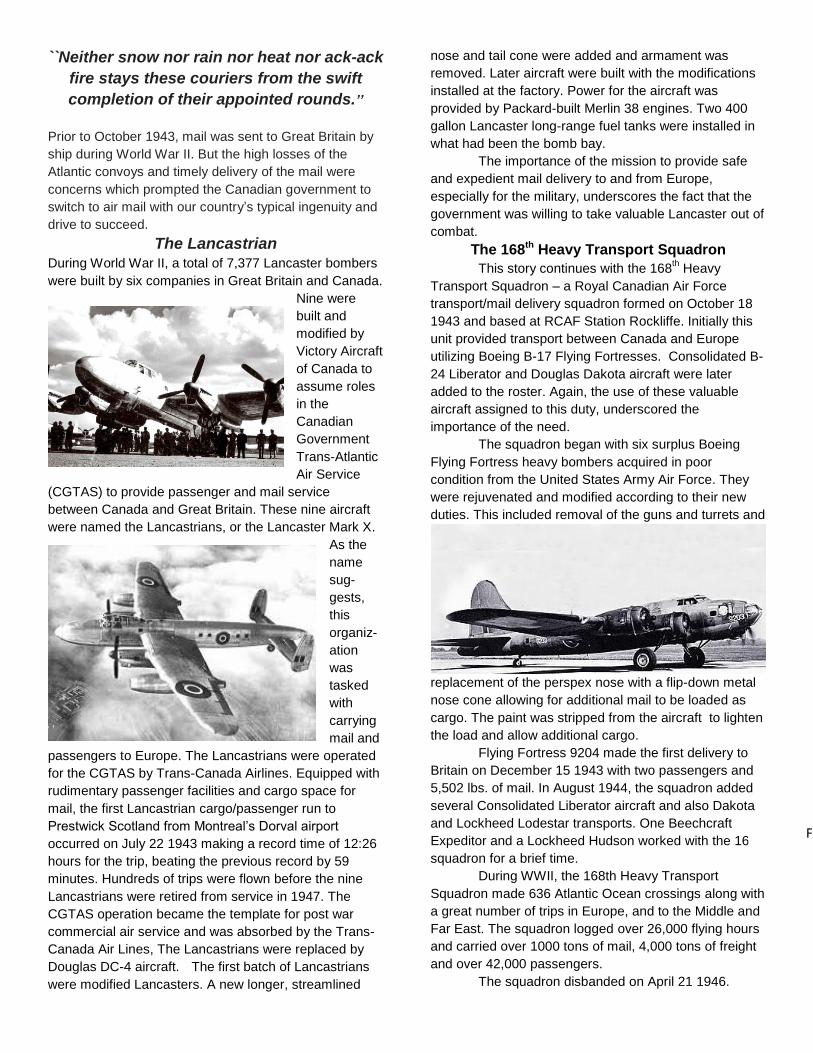
The Lancastrian During World War II, a total of 7,377 Lancaster bombers
were built by six companies in Great Britain and Canada.
Nine were
built and
modified by
Victory Aircraft
of Canada to
assume roles
in the
Canadian
Government
Trans-Atlantic
Air Service
(CGTAS) to provide passenger and mail service
between Canada and Great Britain. These nine aircraft
were named the Lancastrians, or the Lancaster Mark X.
As the
name
sug-
gests,
this
organiz-
ation
was
tasked
with
carrying
mail and
passengers to Europe. The Lancastrians were operated
for the CGTAS by Trans-Canada Airlines. Equipped with
rudimentary passenger facilities and cargo space for
mail, the first Lancastrian cargo/passenger run to
Prestwick Scotland from Montreal’s Dorval airport
occurred on July 22 1943 making a record time of 12:26
hours for the trip, beating the previous record by 59
minutes. Hundreds of trips were flown before the nine
Lancastrians were retired from service in 1947. The
CGTAS operation became the template for post war
commercial air service and was absorbed by the Trans-
Canada Air Lines, The Lancastrians were replaced by
Douglas DC-4 aircraft. The first batch of Lancastrians
were modified Lancasters. A new longer, streamlined
nose and tail cone were added and armament was
removed. Later aircraft were built with the modifications
installed at the factory. Power for the aircraft was
provided by Packard-built Merlin 38 engines. Two 400
gallon Lancaster long-range fuel tanks were installed in
what had been the bomb bay.
The importance of the mission to provide safe
and expedient mail delivery to and from Europe,
especially for the military, underscores the fact that the
government was willing to take valuable Lancaster out of
combat.
The 168th Heavy Transport Squadron
This story continues with the 168th Heavy
Transport Squadron – a Royal Canadian Air Force
transport/mail delivery squadron formed on October 18
1943 and based at RCAF Station Rockliffe. Initially this
unit provided transport between Canada and Europe
utilizing Boeing B-17 Flying Fortresses. Consolidated B-
24 Liberator and Douglas Dakota aircraft were later
added to the roster. Again, the use of these valuable
aircraft assigned to this duty, underscored the
importance of the need.
The squadron began with six surplus Boeing
Flying Fortress heavy bombers acquired in poor
condition from the United States Army Air Force. They
were rejuvenated and modified according to their new
duties. This included removal of the guns and turrets and
replacement of the perspex nose with a flip-down metal
nose cone allowing for additional mail to be loaded as
cargo. The paint was stripped from the aircraft to lighten
the load and allow additional cargo.
Flying Fortress 9204 made the first delivery to
Britain on December 15 1943 with two passengers and
5,502 lbs. of mail. In August 1944, the squadron added
several Consolidated Liberator aircraft and also Dakota
and Lockheed Lodestar transports. One Beechcraft
Expeditor and a Lockheed Hudson worked with the 168th
squadron for a brief time.
During WWII, the 168th Heavy Transport
Squadron made 636 Atlantic Ocean crossings along with
a great number of trips in Europe, and to the Middle and
Far East. The squadron logged over 26,000 flying hours
and carried over 1000 tons of mail, 4,000 tons of freight
and over 42,000 passengers.
The squadron disbanded on April 21 1946.
Figure 1
Sadly, many of the complexities of the British
Commonwealth Air Training Plan have passed on with
the men and women who experienced it first-hand.
Today, many of those with a deep interest in the Plan
don’t have these resources to answer many of the
simplest questions. The Link Trainer poses many
questions about its role and operation during World War
II which will be tough to find answers. This flight
simulator was a crucial component to the success of the
British Common-wealth Air Training Plan and overall
victory for the Allied countries in World War II. Although
we don’t have all the answers, we hope to present a
reasonable recounting of the Link Trainer and its usage
in the Plan,
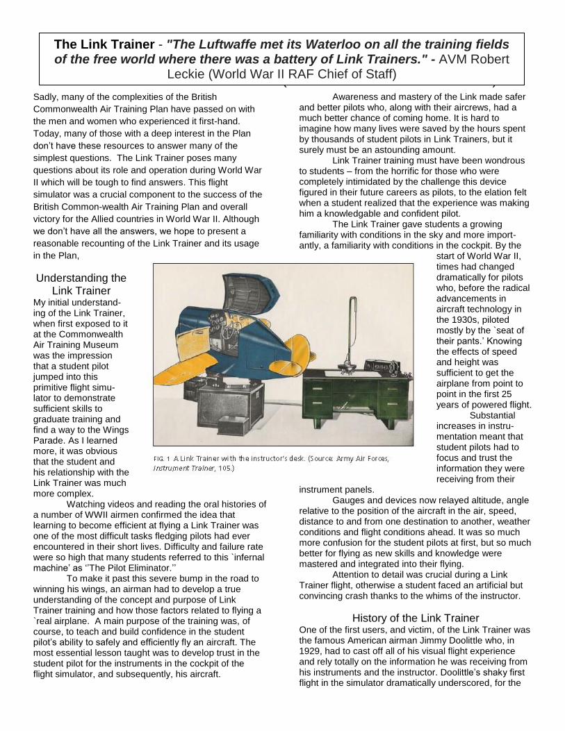
Understanding the Link Trainer
My initial understand-ing of the Link Trainer, when first exposed to it at the Commonwealth Air Training Museum was the impression that a student pilot jumped into this primitive flight simu-lator to demonstrate sufficient skills to graduate training and find a way to the Wings Parade. As I learned more, it was obvious that the student and his relationship with the Link Trainer was much more complex. Watching videos and reading the oral histories of a number of WWII airmen confirmed the idea that learning to become efficient at flying a Link Trainer was one of the most difficult tasks fledging pilots had ever encountered in their short lives. Difficulty and failure rate were so high that many students referred to this `infernal machine’ as ‘’The Pilot Eliminator.’’ To make it past this severe bump in the road to winning his wings, an airman had to develop a true understanding of the concept and purpose of Link Trainer training and how those factors related to flying a `real airplane. A main purpose of the training was, of course, to teach and build confidence in the student pilot’s ability to safely and efficiently fly an aircraft. The most essential lesson taught was to develop trust in the student pilot for the instruments in the cockpit of the flight simulator, and subsequently, his aircraft.
Awareness and mastery of the Link made safer and better pilots who, along with their aircrews, had a much better chance of coming home. It is hard to imagine how many lives were saved by the hours spent by thousands of student pilots in Link Trainers, but it surely must be an astounding amount. Link Trainer training must have been wondrous to students – from the horrific for those who were completely intimidated by the challenge this device figured in their future careers as pilots, to the elation felt when a student realized that the experience was making him a knowledgable and confident pilot. The Link Trainer gave students a growing familiarity with conditions in the sky and more import-antly, a familiarity with conditions in the cockpit. By the
start of World War II, times had changed dramatically for pilots who, before the radical advancements in aircraft technology in the 1930s, piloted mostly by the `seat of their pants.’ Knowing the effects of speed and height was sufficient to get the airplane from point to point in the first 25 years of powered flight. Substantial increases in instru-mentation meant that student pilots had to focus and trust the information they were receiving from their
instrument panels. Gauges and devices now relayed altitude, angle relative to the position of the aircraft in the air, speed, distance to and from one destination to another, weather conditions and flight conditions ahead. It was so much more confusion for the student pilots at first, but so much better for flying as new skills and knowledge were mastered and integrated into their flying. Attention to detail was crucial during a Link Trainer flight, otherwise a student faced an artificial but convincing crash thanks to the whims of the instructor.
History of the Link Trainer One of the first users, and victim, of the Link Trainer was the famous American airman Jimmy Doolittle who, in 1929, had to cast off all of his visual flight experience and rely totally on the information he was receiving from his instruments and the instructor. Doolittle’s shaky first flight in the simulator dramatically underscored, for the
The Link Trainer - "The Luftwaffe met its Waterloo on all the training fields of the free world where there was a battery of Link
Trainers." - AVM Robert Leckie (World War II RAF Chief of Staff)
The Link Trainer - "The Luftwaffe met its Waterloo on all the training fields of the free world where there was a battery of Link Trainers." - AVM Robert
Leckie (World War II RAF Chief of Staff)

U.S. Army Air Corps, that this type of simulator training was ever so essentially necessary for pilots. Instructors were also defying flying tradition in the 1930s by forging better methods of instrument flying. In the air forces, even if the instructor was of a rank lower than the student, students soon realized that in order to earn their wings and survive the rigors of flying an aircraft in war, they had to appreciate and absorb the superior knowledge of the instructor and the valuable advice given them. The inventor of the Link Trainer, Edwin Link (1904-1981) enjoyed a short career as a aircraft barnstormer before embarking on his mission to build an aircraft flight simulator. During the depression, business was slow at his flying school so Link took a job at his father’s player-piano and organ manufacturing company in Binghamton, New York while he continued to provide flying lessons at a nearby airfield. From parts scavenged from player-pianos and organs, he built his first simple aircraft trainer – a device that tilted and rotated on a fixed base in a fashion similar to that of a aircraft in flight. His idea was to provide flying students with a way to shorten the time required to master piloting an airplane with safety and without the expense of using an actual aircraft. Link’s initial trainers provided the basics - control maneuvers – rudder, aileron and elevator controls and recovering aircraft from abnormal attitudes. The Link Trainer was designed to be a realistic flightless facsimile of an actual aircraft flight in a cockpit for one. The idea didn’t catch on initially and Link’s flying school was the sole operation using his trainer for its
intended purpose for the first five years. It was however, a big hit at the amusement parks. As Link started introducing more instruments which simulated those found in an actual cockpit, flying instruction quickly transitioned to meeting the essential needs of pilots to know instrument flying. Sessions in the Link Trainer were an inherently better way to learn flying than in an airplane shrouded in darkness and bad weather. Adding a hood to the Link Trainer, which eliminated a student’s view of the physical sights around the aircraft, made it an absolutely realistic instrument flight simulator. In 1934, in order to obtain much needed sales for his trainer, Link set up a meeting with the United States Army Air Corp. He flew his plane from Binging-ham to Newark New Jersey where army officials were awaiting Links sales pitch. He actually made the sale while approaching and landing at the airport in darkness and unfavourable weather. His customers were so impressed with his landing, in large part thanks to his abilities with instrument flying sharpened by sessions in his flight simulator, that they immediately ordered six Link Trainers at a cost of $2100. His luck continued when President Franklin Roosevelt, unhappy with the failure of private carriers to provide a reliable airmail system in the United States, cancelled their existing contracts. Airmail duties were transferred to the United States Air Corps. This was a disaster for the air corps which in the first two months lost a dozen aircraft and pilots to darkness and bad weather. The air corps adopted the obvious solution to this carnage – provide pilots with instrument training in the Link Trainer.
Above: A record of two Link Training Instructional exercises flew by Sgt. E.F. Baillie of 77 Flight, December 1943. The lines are red. The first exercise has the following instructor notations: First Exercise: Ex. 1, Date-15-12-43, Link-4, Time .50. Climb O.K. – HTS. 300’ Gained – Turns Quite Good But Flying Nose High – A/S. Good. Except in Turns. (Dropped to 140-150).- Courses. Quite Good. – Glide Very Steady 110.5. – Final Control. G.A. C. Fairhall. Second Exercise: Ex. 203, Date 17-12-43, Link 4, Time .55., Climb Steady, Turns O.K. with gyro., Compass turn rather weak, HTS. Well maintained, Courses good, R.A. Control Good on whole, I.F. steady but erratic R/A., Climb Fairly Good, Final Control, Av., C. Fairhall.
Word got out and many commercial airlines, seeing the improvement in flying of the air corps pilots, adopted the Link Trainer to assist their pilots to learn better instrument flying skills. Sales were good, but the bonanza in the flight simulator business was to come with the inevitable global war. Prior to World War II, the Allied Air Forces knew that it would take over-whelming fleets of aircraft and aircrews with superior skills to win. They achieved both with higher volume aircraft manufacturing capabilities in their respective countries and superior aircrews with pilots who were better at instrument flying than the enemy, thanks in large part to the Link Trainer. The enemy lacked any similar advantage to Link Trainer training. In World War II, over 10,000 Link Trainers were built for the Allied military - half of them at a Canadian plant in Ontario. The Link Manufacturing Company prospered and continues to build flight simulators for the aerospace industry to this day.
The Link Manufacturing Company in Canada
In Canada, the decision to set up a Link Trainer manufacturing plant in Canada was made by Edwin Link in 1937. In order to provide these valuable flight simulators to the air forces of the British Commonwealth, they had to be manufactured in Commonwealth countries. Canada, because of its vast resources, large available work force and safe distance from the fighting was a logical location to set up a plant. Link chose Gananoque Ontario which was close to his summer house on Chismore’s Point, an island just east of this small town. Link, had an easy commute in his own aircraft between his plants in Canada and the U.S.. The plant on Mill Street opened with sixty employees. A local paper reported that the company had obtained an order from the RCAF for eighty of the flight simulators for the British Commonwealth Air Training Plan. In order to fill this $1.5 million contract, the plant initiated a 24 hour, seven day a week production schedule. By the end of World War II, the workforce
grew to 200 employees who manufactured 5,000 trainers for 35 countries. After World War II, the Canadian subsidiary transitioned into the manufacture of quality cedar boats while Edwin Link went on to other projects such as building underwater rescue units, helium underwater breathing apparatus and NASA’s Lunar Landing Module flight simulator.
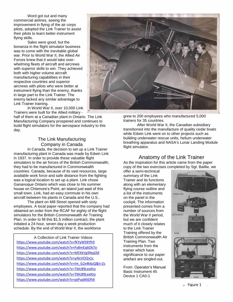
Anatomy of the Link Trainer As the inspiration for this article came from the paper copy of the two exercises completed by Sgt. Baillie, we offer a semi-technical summary of the Link Trainer and its functions along with an elementary flying course outline and a list of the instruments on the panel in the cockpit. The information presented comes from a number of sources from the World War II period, but we are confident much of it closely relates to the Link Trainer Training offered by the British Commonwealth Air Training Plan. Two instruments from the trainer which have significance to our paper artefact are singled-out.
From: Operator’s Manual Basic Instrument 45 Device 1 CA0-1
A Collection of Link Trainer Videos
https://www.youtube.com/watch?v=fKYyWS9Yfr0
https://www.youtube.com/watch?v=Fy8mEq6Ok7o
https://www.youtube.com/watch?v=MEKkVg9NqGM
https://www.youtube.com/watch?v=yAlcVOl2x1c
https://www.youtube.com/watch?v=Im_G2x4k6zQ&t=2s
https://www.youtube.com/watch?v=TMcB9LexKto
https://www.youtube.com/watch?v=TMcB9LexKto
https://www.youtube.com/watch?v=qtPvpMtDft4
Figure 1

6. Main Components (fig. 1) - The complete unit consists of a movable fuselage, a revolving octagon, a square fixed base and an operator's desk. The fuselage, revolving octagon and base are contained in one unit, commonly referred to as the "trainer" while the operator's desk (fig. 2) is a separate unit connected electrically and by flexible shafts to the trainer. The fuselage is mounted on a universal joint, which permits pitch and bank movements. The universal joint is bolted to the revolving octagon. The revolving octagon is attached to a spindle mounted in the main bearing housing in the square fixed base of the trainer. The fuselage, revolving octagon, and spindle are free to rotate indefinitely in either direction. a. fuselage (fig. 3) -… The center section, which resembles the cockpit of a modern single-seater
airplane, houses the pilot's instrument panel, wheel or stick and rudder controls, pilot’s seat, trim controls, radio navigation and direction finding equipment, throttle, landing gear and wing position controls, shutter controls, and four moonbeam spotlights. (4) The pilot's instrument panel forms a partition between the cockpit and the forward section of the fuselage and is equipped with flight and engine instruments similar to an aircraft equipped for instrument flight. d. Operator's Desk (fig. 2) -. The operator's desk is constructed of wood and is 5 feet 11 1/2 inches long, 3 feet wide, and 3 feet high: The drawer arrangement is similar to an executive desk, there being a center drawer, two drawers on the right-hand side, and
three drawers on the left-hand side. An automatic radio range quadrant assembly is mounted on tubular metal framework above the desk, its transmitter unit and receiving amplifier unit being housed in the lower left-hand drawer and the lower right-hand drawer, respectively. The radio control unit and the station bearing transmitter are conveniently located in the center drawer of the desk, the upper left-hand drawer is used to store the automatic radio range quadrant that is not being used, while the upper right-hand drawer and the left-hand center drawer are available for storage of microphone and headphones, text books, radio range
Figure 1
Figure 2
Figure 2
Figure 3

charts, maps, etc. A remote instrument case for the operator is mounted on brackets on the left rear corner of the desk. Wind-speed and wind-direction controls are mounted on the right-hand end of the desk. The automatic radio range antenna and preamplifier are mounted on the recorder which is located on the top of the desk. An operator's microphone and earphones complete the desk equipment. Provision is also made for connecting additional sets of earphones.
The Automatic Recorder and Wind Drift (Fig. 4) – mechanisms most closely relate to Sgt. Baillie’s exercises – to determine all variables associated with the ground track recorded by the Link Trainer.
Wind Drift. When the elements of trainer heading, air speed, wind direction, and wind speed are fed into the wind-drift mechanism of the trainer, it automatically solves the wind triangle problem, resulting in outputs of track and ground speed as traced by the automatic recorder on the operator's desk chart. These elements are introduced into the mechanism as follows: ( 1) Heading: From trainer rotation through take-off gearing to the main spindle. (2) Air speed: Through an air-speed cable actuated as a result of changes in trainer and air speed and altitude. (3) Wind direction: From the manual wind-direction control on the operator's desk through a flexible drive shaft. ( 4) Wind speed : From the manual windspeed control on the operator's desk through a flexible drive shaft. ( 5) From these inputs, the wind-drift mechanism mechanically solves the wind triangle problem, producing the remaining side or vector quantity which represents the track and ground speed of the trainer. These outputs are charged from mechanical to electrical form for transmission to the automatic recorder and are refleted in its behavior as it traces the flight path of the trainer on the desk chart.
38. Automatic Recorder - The automatic recorder (fig. 4) located on top of the operator's desk, travels over a chart or map on the desk, leaving an inked path of the course flown by the trainer. The recorder rate of travel and direction of travel result from the combining of wind direction wind speed, "true" air speed and trainer heading by the wind-drift mechanism in the trainer base. A pointer (11) on top of the recorder provides an indication of recorder travel. The recorder drive wheels are equipped with a two speed gear shifting device (fig. 36). The low speed gears are used for ordinary instrument and radio problems, while the high speed gears are used for instrument landing problems. 30. WIND DRIFT MECHANISM. a. The wind drift mechanism, connected to the automatic recorder, introduces the effect of various wind

directions and velocities on Trainer heading as traced by the automatic recorder. b. The mechanism consists of an assembly of gear trains so arranged that when the various elements of the wind drift problem are fed into it, the output is track and ground speed. c. By turning the wind direction and wind velocity cranks, located on the right-hand side of the instructor's desk, the instructor, either before or during a problem, can apply wind velocity from zero up to 60 mph and wind direction from zero through 360° to Trainer heading and air speed… Etchings were usually done on a map or chart larger than the exercise record so we are not 100% if our paper artefact is an actual tracing. We believe it was a pre-printed evaluation form showing the route(s) to be followed by the instructor and student. The comments on the paper suggest Sgt. Baillee did well flying the courses given.
Operation of and Training On the Link Trainer
This is basic information about the Link Trainer with a description of the a typical course outline, basic and advanced exercises as well as the instruments on pilot’s panel in the cockpit.
Link Trainer Elementary Course Outline (Herben Course on the Link Trainer 1939) 1. Effect of controls. 2. Further effect of controls. 3. Straight and level flying. 4. Stalling, climbing, gliding. 5. Effect of controls when banked. 6. Medium turns, power and gliding. 7. Compass, functioning of T. and B. Indicator, and other instruments. 8. Compass errors and turning on to courses. 9. Drills for taxying, take-off, approach, 10. landing and spinning.
The complete elementary course takes approximately seven and a half to eight hours, by which time the pupil has complete mastery of the Trainer and allows time for general revision and practice. Items I to 6 can be completed in five to six hours, but the full course is very desirable, as Items 7, 8 and 9 save a lot of time in the air.
Basic Exercises - Familiarization - Constant Altitude with Varied Airspeed - Nomral Climb – increased power and reduced
airspeed - Straight and Level Flight while Maintaining
Headings - Straight Climbs and Decents - Turns - Turns – 90 and 180 degree - Timed Turns - Patterns - Climbing and Dexcending Turns
- Desecents to Predetermined Headings and Altitudes
- Related Instruments
More Advanced - Radio Discussion and Procedures - Instrument Trainer Charts - Range Flying Training - Radio Compass Trainer Exercises - Instrument Landing - Radio Navigation Flight
The Instruments (from Instrument Flying – Ground Trainer – 1943) - airspeed indicator - directional gyro - artificial horizon - altimeter - turn and bank indicator - vertical speed indicator - tachonmeter - magnetic compass - radio compass and the localizer indicator
Overall the Link Trainer was a valuable component of a pilot’s training in World War II – perhaps the most valuable. Some of the mysteries have been solved with these articles. Anyone with more answers, please pass them on to us. Thank you for supporting the Commonwealth Air Training Plan Museum. The next issue of CONTACT will be released in November 2020.
Figure 4


![The BritonsThe Commonwealth [p. 11] · 1. A British recruiting poster addressing the Commonwealth people (1940). (Imperial War Museum, London) ... After the 1957 Treaty of Rome, the](https://static.fdocuments.net/doc/165x107/605847bea04ba37bcf7ce581/the-britonsthe-commonwealth-p-11-1-a-british-recruiting-poster-addressing-the.jpg)
