Commissioning MMS: Challenges and Lessons Learned · PDF fileCommissioning MMS: Challenges and...
15
978-1-4673-7676-1/16/$31.00 ©2016 IEEE 1 Commissioning MMS: Challenges and Lessons Learned Paul Wood Southwest Research Institute 6220 Culebra Road San Antonio, TX 78238 210-522-3275 [email protected] Jennifer Reiter Laboratory for Atmospheric and Space Physics 1234 Innovation Drive Boulder, CO 80303 303-735-4410 [email protected] John Stone Southwest Research Institute 6220 Culebra Road San Antonio, TX 78238 210-522-5073 [email protected] Cheryl Gramling NASA-Goddard Space Flight Center Code 595, Greenbelt Road Greenbelt Maryland 20771 301-286-8002 [email protected] Patrick Smith Laboratory for Atmospheric and Space Physics 1234 Innovation Drive Boulder, CO 80303 303-735-0921 [email protected] Abstract—This paper discusses commissioning of NASA’s Magnetospheric MultiScale (MMS) Mission. The mission includes four identical spacecraft with a large, complex set of instrumentation. The planning for and execution of commissioning for this mission is described. The paper concludes by discussing lessons learned. TABLE OF CONTENTS 1. INTRODUCTION ....................................................... 1 2. COMMISSIONING BACKGROUND ........................... 2 3. COMMISSIONING PLANNING.................................. 4 4. COMMISSIONING EXECUTION ............................... 8 5. LESSONS LEARNED............................................... 11 6. CONCLUSIONS ....................................................... 13 ACKNOWLEDGEMENTS ............................................ 14 REFERENCES............................................................. 14 BIOGRAPHY .............................................................. 15 1. INTRODUCTION MMS [1] consists of a constellation of four (4) identical spin-stabilized spacecraft (S/C) with numerous instruments and processing modules making up the Solving Magnetospheric Acceleration, Reconnection, and Turbulence (SMART) Instrument Suite (IS). The S/C fly in a tetrahedral formation in highly elliptical orbits, necessitating precise maneuvers and onboard navigation. As the purpose of these S/C is scientific study, they are normally referred to as observatories, and, when we are referring to the entire satellite, we will use that term. The observatory is logically broken into two (2) pieces, the spacecraft bus, and the payload. We will discuss commissioning both. MMS commissioning included many activities such as spacecraft bus activation, low-voltage turn on, deployments, and initial high-voltage activities; a shadow season with specialized commissioning activities; a post-shadow commissioning period including high-voltage activation, cross-calibration, and interference campaigns; and preparation for nominal science operations. In addition, each spacecraft performed thirty-two (32) maneuvers during the commissioning period. Spacecraft bus commissioning included bus component activation, verification/characterization of the Radio Frequency (RF) communication, attitude control, onboard navigation, thermal control, and power systems, and included maneuvers to achieve mission orbit and attitude. Over the same time span, payload commissioning focused on initial activation and low voltage checkout of each sensor, boom deployments, gradual power up of high voltage instruments, and coordination of activities across the constellation. Almost all commissioning activities were completed at least four (4) times across the MMS constellation, although there were a few activities that were performed on a subset of observatories. Ground system commissioning included testing to identify and resolve network and multi-facility interface issues, which could not be tested prior to launch. Planning for MMS commissioning addressed several critical activities and required coordination across multiple organizations, facilities, and resources including terrestrial https://ntrs.nasa.gov/search.jsp?R=20160000874 2018-05-18T14:04:47+00:00Z
Transcript of Commissioning MMS: Challenges and Lessons Learned · PDF fileCommissioning MMS: Challenges and...
978-1-4673-7676-1/16/$31.00 ©2016 IEEE
1
Commissioning MMS: Challenges and Lessons Learned Paul Wood
Southwest Research Institute 6220 Culebra Road
San Antonio, TX 78238 210-522-3275
Jennifer Reiter Laboratory for Atmospheric and
Space Physics 1234 Innovation Drive
Boulder, CO 80303 303-735-4410
John Stone Southwest Research Institute
6220 Culebra Road San Antonio, TX 78238
210-522-5073 [email protected]
Cheryl Gramling
NASA-Goddard Space Flight Center
Code 595, Greenbelt Road
Greenbelt Maryland 20771
301-286-8002
Patrick Smith Laboratory for Atmospheric and
Space Physics 1234 Innovation Drive
Boulder, CO 80303 303-735-0921
Abstract—This paper discusses commissioning of NASA’s
Magnetospheric MultiScale (MMS) Mission. The mission
includes four identical spacecraft with a large, complex set of
instrumentation. The planning for and execution of
commissioning for this mission is described. The paper
concludes by discussing lessons learned.
TABLE OF CONTENTS
1. INTRODUCTION ....................................................... 1 2. COMMISSIONING BACKGROUND ........................... 2 3. COMMISSIONING PLANNING .................................. 4 4. COMMISSIONING EXECUTION ............................... 8 5. LESSONS LEARNED ............................................... 11 6. CONCLUSIONS ....................................................... 13 ACKNOWLEDGEMENTS ............................................ 14 REFERENCES............................................................. 14 BIOGRAPHY .............................................................. 15
1. INTRODUCTION
MMS [1] consists of a constellation of four (4) identical
spin-stabilized spacecraft (S/C) with numerous instruments
and processing modules making up the Solving
Magnetospheric Acceleration, Reconnection, and
Turbulence (SMART) Instrument Suite (IS). The S/C fly in
a tetrahedral formation in highly elliptical orbits,
necessitating precise maneuvers and onboard navigation.
As the purpose of these S/C is scientific study, they are
normally referred to as observatories, and, when we are
referring to the entire satellite, we will use that term. The
observatory is logically broken into two (2) pieces, the
spacecraft bus, and the payload. We will discuss
commissioning both.
MMS commissioning included many activities such as
spacecraft bus activation, low-voltage turn on, deployments,
and initial high-voltage activities; a shadow season with
specialized commissioning activities; a post-shadow
commissioning period including high-voltage activation,
cross-calibration, and interference campaigns; and
preparation for nominal science operations. In addition,
each spacecraft performed thirty-two (32) maneuvers during
the commissioning period.
Spacecraft bus commissioning included bus component
activation, verification/characterization of the Radio
Frequency (RF) communication, attitude control, onboard
navigation, thermal control, and power systems, and
included maneuvers to achieve mission orbit and attitude.
Over the same time span, payload commissioning focused
on initial activation and low voltage checkout of each
sensor, boom deployments, gradual power up of high
voltage instruments, and coordination of activities across the
constellation. Almost all commissioning activities were
completed at least four (4) times across the MMS
constellation, although there were a few activities that were
performed on a subset of observatories. Ground system
commissioning included testing to identify and resolve
network and multi-facility interface issues, which could not
be tested prior to launch.
Planning for MMS commissioning addressed several critical
activities and required coordination across multiple
organizations, facilities, and resources including terrestrial
https://ntrs.nasa.gov/search.jsp?R=20160000874 2018-05-18T14:04:47+00:00Z
2
and space communication networks. Mission planning
responsibilities were performed by four (4) groups: (1)
MMS program planners, responsible for building the long
term (strategic) and day to day (tactical) schedule for
payload commissioning coordinated with spacecraft
activities, maneuvers, and ground contacts; (2) the Mission
Operations Center (MOC), responsible for developing the
tools necessary for S/C deck operations; the (3) Payload
Operations Center (POC), responsible for planning the
details of activities to be performed on the payload during
each contact; and (4) Instrument Team Facilities (ITFs),
responsible for providing instrument and investigation
specific activity plans and instructions.
As the commissioning process proceeded from planning to
execution, several challenges developed. The baseline
commissioning plan quickly grew in complexity prior to
launch as the amount of effort to commission four (4)
spacecraft, the strict sequencing of operations to avoid
instrument operational conflicts, and other factors had to be
accommodated by the plan. Once under way, the need to
adapt the schedule to deal with anomalies and investigate
science targets of opportunity, the uncertainties posed by the
limitations of ground emulation hardware, and delayed
delivery of some instrument inputs began to require more
instrument concurrent operations and last minute
scheduling. However, thanks to solid preparation,
commissioning was able to proceed with minimal impact
from these potential disruptions.
2. COMMISSIONING BACKGROUND
The Science
The MMS Mission is an international, multi-institutional
effort funded by NASA under the Solar-Terrestrial Probes
program to “enable an understanding of magnetic
reconnection in the boundary layers of the Earth’s
magnetosphere, which is formed by its interaction with the
solar wind.” [1] Magnetic reconnection occurs when the
magnetic fields embedded in collision less plasmas become
interconnected, converting magnetic field energy into the
kinetic energy of the plasma ions and electrons [2]. In order
to determine that magnetic reconnection is occurring,
concurrent, three-dimensional maps of particle distribution
functions, electric and magnetic fields, and plasma waves
need to be made [3]. These measurement requirements flow
directly into the mission configuration. The requirement for
concurrent, three-dimensional (3D) measurements at
varying temporal scales drives the use of a four (4)
spacecraft tetrahedron; and the requirement for particle, and
fields and waves measurements drives the instrument
configuration of the observatories. Observations are
separated into two (2) distinct science phases. Phase 1a
observations occur on the dayside with crossings into the
magnetosheath, while Phase 2 observations will occur in the
magnetotail. A commissioning phase (Phase 0) occurred
prior to Phase 1a, and a transitional phase (Phase 2a)
between Phases 1a and 2b.
Each MMS observatory orbits in a 1.2 x 12Re orbit for Phase
1 while maintaining a minimum quality tetrahedron
throughout the science Region of Interest (ROI).
Tetrahedron quality is based on the six (6) tetrahedron side
lengths and the total volume within the tetrahedron. The
tetrahedron is re-sized (ranging from approximately 160 to
10 km spacing for Phase 1, 400 to 25 km for Phase 2b) and
re-constituted numerous times throughout the mission
requiring precise locational knowledge.
During the operational phases, MMS collects high-
resolution data in the science ROI where reconnection is
likely to occur, and lower resolution data outside the ROI.
Within the ROI, medium resolution “survey” data are
automatically downlinked for evaluation. Data are
automatically tagged with quality measures, but humans
perform a Scientist in the Loop (SITL) evaluation and
ultimately determine what high-resolution data from a
particular ROI will be downlinked. “Burst” activity data
(the highest resolution data) not selected for downlink are
automatically marked available for reuse by this process;
“burst” activity data downlinked are automatically marked
for reuse once they have been successfully downlinked.
The Observatories
Each MMS observatory is functionally identical. Attitude
determination and control is provided by a complement of
the Danish Technical University’s four (4)-head star sensor
and an Adcole Digital Sun Sensor, supplemented with
ground-based attitude determination software. Due to the
timelines for formation maneuver execution and the
requirement on interspacecraft time knowledge, MMS flies
an onboard orbit determination system, supplied by
Navigator, a specialized Global Positioning System (GPS)
receiver with weak signal acquisition, a high-resolution and
accuracy accelerometer from Zin Technologies, and the
Goddard Enhanced Onboard Navigation System (GEONS),
an extended Kalman filter-based orbit estimator. A
complement of twelve (12)-thrusters (banks of four (4)-lbf
radial thrusters on two side panels and two (2) 1-lbf axial
thrusters on the top and bottom decks) execute both attitude
and orbit maneuvers. Maneuver control can be executed
open loop or via an onboard delta-V or delta-H controller
developed for MMS to enable execution of precision
maneuvers on a spinning spacecraft with flexible body
motion. The spacecraft bus was built in-house at NASA’s
Goddard Space Flight Center (GSFC).
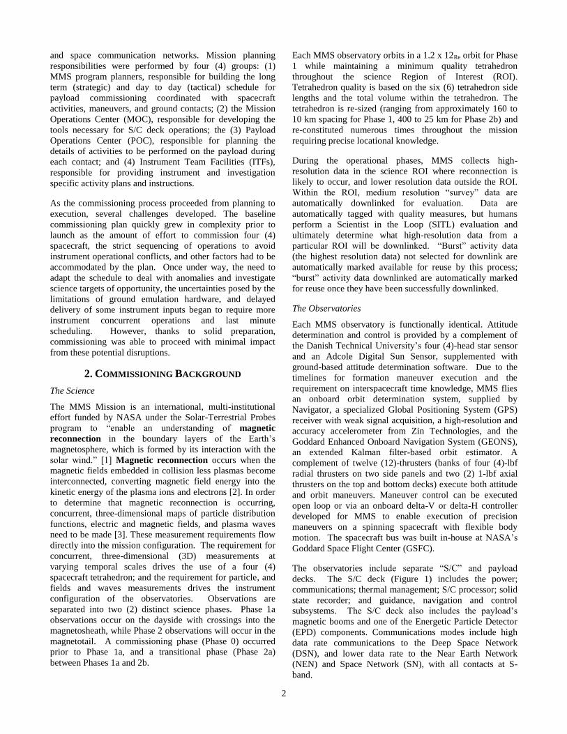
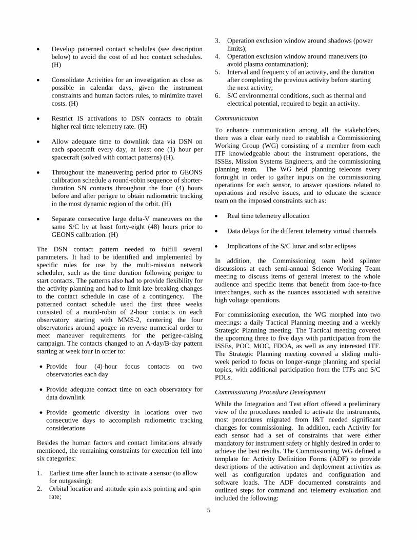
The observatories include separate “S/C” and payload
decks. The S/C deck (Figure 1) includes the power;
communications; thermal management; S/C processor; solid
state recorder; and guidance, navigation and control
subsystems. The S/C deck also includes the payload’s
magnetic booms and one of the Energetic Particle Detector
(EPD) components. Communications modes include high
data rate communications to the Deep Space Network
(DSN), and lower data rate to the Near Earth Network
(NEN) and Space Network (SN), with all contacts at S-
band.
3
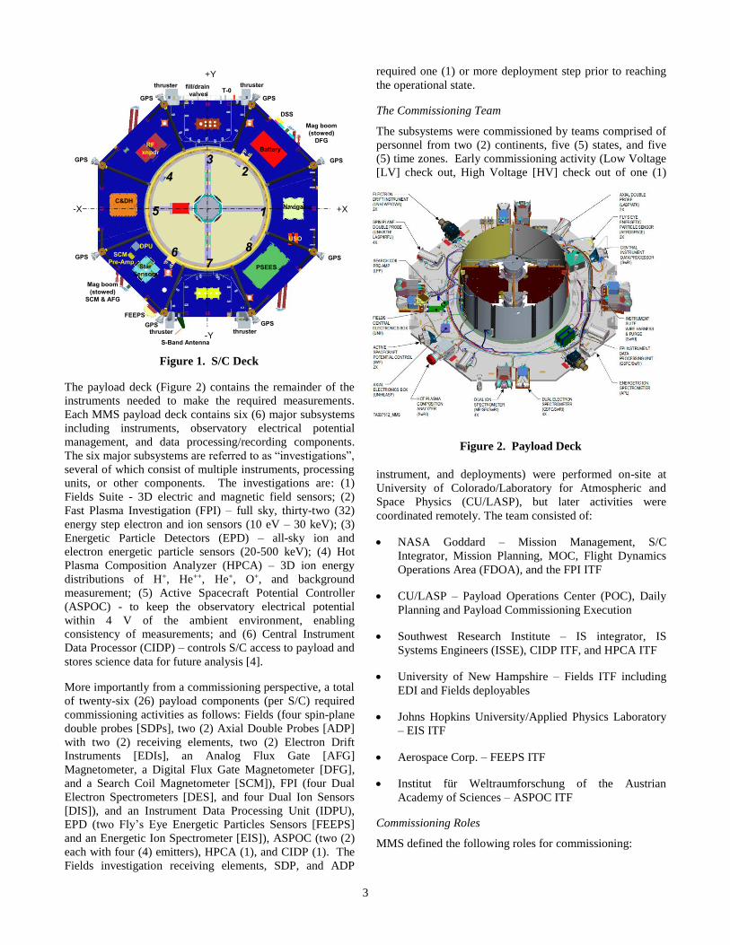
The payload deck (Figure 2) contains the remainder of the
instruments needed to make the required measurements.
Each MMS payload deck contains six (6) major subsystems
including instruments, observatory electrical potential
management, and data processing/recording components.
The six major subsystems are referred to as “investigations”,
several of which consist of multiple instruments, processing
units, or other components. The investigations are: (1)
Fields Suite - 3D electric and magnetic field sensors; (2)
Fast Plasma Investigation (FPI) – full sky, thirty-two (32)
energy step electron and ion sensors (10 eV – 30 keV); (3)
Energetic Particle Detectors (EPD) – all-sky ion and
electron energetic particle sensors (20-500 keV); (4) Hot
Plasma Composition Analyzer (HPCA) – 3D ion energy
distributions of H+, He++, He+, O+, and background
measurement; (5) Active Spacecraft Potential Controller
(ASPOC) - to keep the observatory electrical potential
within 4 V of the ambient environment, enabling
consistency of measurements; and (6) Central Instrument
Data Processor (CIDP) – controls S/C access to payload and
stores science data for future analysis [4].
More importantly from a commissioning perspective, a total
of twenty-six (26) payload components (per S/C) required
commissioning activities as follows: Fields (four spin-plane
double probes [SDPs], two (2) Axial Double Probes [ADP]
with two (2) receiving elements, two (2) Electron Drift
Instruments [EDIs], an Analog Flux Gate [AFG]
Magnetometer, a Digital Flux Gate Magnetometer [DFG],
and a Search Coil Magnetometer [SCM]), FPI (four Dual
Electron Spectrometers [DES], and four Dual Ion Sensors
[DIS]), and an Instrument Data Processing Unit (IDPU),
EPD (two Fly’s Eye Energetic Particles Sensors [FEEPS]
and an Energetic Ion Spectrometer [EIS]), ASPOC (two (2)
each with four (4) emitters), HPCA (1), and CIDP (1). The
Fields investigation receiving elements, SDP, and ADP
required one (1) or more deployment step prior to reaching
the operational state.
The Commissioning Team
The subsystems were commissioned by teams comprised of
personnel from two (2) continents, five (5) states, and five
(5) time zones. Early commissioning activity (Low Voltage
[LV] check out, High Voltage [HV] check out of one (1)
instrument, and deployments) were performed on-site at
University of Colorado/Laboratory for Atmospheric and
Space Physics (CU/LASP), but later activities were
coordinated remotely. The team consisted of:
NASA Goddard – Mission Management, S/C
Integrator, Mission Planning, MOC, Flight Dynamics
Operations Area (FDOA), and the FPI ITF
CU/LASP – Payload Operations Center (POC), Daily
Planning and Payload Commissioning Execution
Southwest Research Institute – IS integrator, IS
Systems Engineers (ISSE), CIDP ITF, and HPCA ITF
University of New Hampshire – Fields ITF including
EDI and Fields deployables
Johns Hopkins University/Applied Physics Laboratory
– EIS ITF
Aerospace Corp. – FEEPS ITF
Institut für Weltraumforschung of the Austrian
Academy of Sciences – ASPOC ITF
Commissioning Roles
MMS defined the following roles for commissioning:
Nov. 18 - 21, 2014 MMS FOR/ORR Section 4 – 16
+X-X
-Y
+Y
RF
xnpdr
1
23
4
5
67
8
PSEES
Battery
C&DH
Star
Sensors
Mag boom
(stowed)
DFG
DPU
Mag boom
(stowed)
SCM & AFG
S-Band Antenna
FEEPS
SCM
Pre-Amp
Navigator
USO
DSS
Spacecraft Deck Components
- 1 IS instrument - 6 thrusters
- 1 IS electronics box - optical bench
- 4 SC electronics boxes - T-0 panel
-8 GPS antennas & LNA - fill/drain valves
(on struts)
Spacecraft Deck Components
• Accelerometers
• AFG - Analog Flux Gate Magnetometer (mounted on boom)
• Battery
• C&DH – Command & Data Handling
• DFG - Digital Flux Gate Magnetometer (mounted on boom)
• DPU - Digital Processing Unit (star sensor
• DSS – Digital Sun Sensor
• FEEPS - Fly’s Eye Energetic Particle Sensors
• Magnetometer booms
• Navigator (GPS)
• PSEES – PSE/EVD – Power Subsystem Electronics/Engine Valve Driver
• RF Components/Transponder
• S-Band Antenna
• SCM - Search-Coil Magnetometer (mounted on boom)
• SCM Pre-amp – Search Coil Magnetometer
• Star Sensors
• USO – Ultra Stable Oscillators
thrusterthruster
thrusterthruster
fill/drain
valvesT-0
GPS
GPS
GPSGPS
GPS
GPS
GPSGPS
(blue = IS components mounted on spacecraft deck or mag boom
Figure 1. S/C Deck
Figure 2. Payload Deck
4
Executive Planner – Coordinate across all the
stakeholders (Project Management, Guidance,
Navigation, and Control [GNC], Propulsion, Thermal,
Power, RF Communications, Command & Data
Handling, POC, ITFs, and the three communication
networks) to establish a master schedule that
incorporates S/C activities (such a maneuvers and bus
calibrations) and IS activities.
Flight Director (FD) – Overall S/C operation,
determines when payload commanding is permitted
within a communications contact.
Product Development Lead (PDL) – Subject matter
experts for the S/C subsystems. They monitor
responses and provide GO/NO GO direction to the FD
as activities are performed.
POC Planner – Assimilate master schedule information
and produce individual activity plans that account for
S/C and IS state, constraints (e.g., orbital location), and
commanding requested by ITFs.
POC FD – Overall responsibility for the IS with a focus
on safely and efficiently completing the scheduled
activities and responding to anomalies.
POC Flight Controller (FC) – Voice of the POC to
coordinate between the MOC and the ITFs, the FC
follows the scheduled activities scripts.
POC Command Controller (CC) – Execute the
commands and scripts that control the activities under
direction of the POC FC & POC FD.
ITF – Subject matter experts for the instruments. They
monitor instrument responses and provide GO/NO GO
direction to the POC as activities are performed.
IS Systems Engineer (ISSEs) – Represent integrated IS
concerns and (usually) act as subject matter experts for
the CIDP. For critical activities such as deployments,
ISSEs provide GO/NO GO direction for the CIDP ITF
and the IS as a whole.
3. COMMISSIONING PLANNING
Commissioning Constraints
With its large complement of instrument sensors, precision
maneuvers, and four observatories, MMS proved unique
among its spacecraft peers. Early on the commissioning
team sought lessons learned from other multi-spacecraft
missions. Cluster, operated by the European Space
Operations Center (ESOC) in Darmstadt, Germany, offered
insights into the human resource limitations and specifics
about MMS predecessor instruments flying on Cluster. In
addition, ESOC offered insights into their methods for
planning maneuvers. Experience from the Time History of
Events and Macroscale Interactions during Substorms
(THEMIS) and the Van Allen Probes (formerly known as the
Radiation Belt Storm Probes [RBSP]) was sought and found
to be minimally applicable, as neither mission had as many
sensors as each MMS observatory, nor the need to execute
precision maneuvers to achieve the correct attitude and
orbital placement.
Based on the feedback from Cluster and experience from
operating other spacecraft from GSFC, the following list of
scheduling rules were instituted to mitigate the impact of
commissioning on the human element, maintain safe
instrument operations, and work within cost constraints. In
the following lists, an (S) represents a soft constraint that
could be broken if needed; an (H) represents a hard
constraint that involved mission safety; and a (~) represents
a hard constraint depending on the ITF team-attributes.
Human factors constraints included:
Plan the entire schedule for six (6) days ON/ one (1)
day OFF per week to allow for one (1) contingency day
per week (S)
Keep similar activities for an investigation in the same
relative time slots each day, and if more than one (1)
event needs to be executed, keep them in same twelve
(12)-hour shift to maintain human element. (S)
If the time slot for a set of activities for an investigation
has to change to a different shift, allow at least two (2)
days between shift changes to allow human factors
adjustment to time change. (~)
Schedule no more than four (4) consecutive days on the
same activity to avoid team burn-out; if one must
perform an activity set for longer than four (4) days, the
schedule should allow for an extra day off before re-
starting activities with that group of personnel. (S)
Follow a 1-1-2 pattern for each new activity to give the
ITF time to work any anomalies or quirks that arise.
[Notionally, this translates to: perform the activity on
S/C #1; wait a day then perform same activity on S/C
#2; wait a day, then perform the activity on S/C #3 &
#4 on the last day. (S)]
Cost constraints on the mission led to requirements for
minimal network scheduling changes and consolidated
travel periods for the ITFs during commissioning. The
onboard navigation system needed a calibration period and
would not be used operationally until after completing all
the deployments, which led to a need for early orbit
radiometric tracking data from the contacts with the
networks. The S/C communication system supported only
Doppler from DSN and NEN, and both range and Doppler
from the SN. However, DSN provided higher data rate and
was schedulable around apogee in the science Region of
Interest. In addition, the flight dynamics team needed two
(2) perigee transits between maneuvers to estimate the orbit
in order to plan the next delta-V maneuver. All of these
contributors led to the following additional set of rules:
5
Develop patterned contact schedules (see description
below) to avoid the cost of ad hoc contact schedules.
(H)
Consolidate Activities for an investigation as close as
possible in calendar days, given the instrument
constraints and human factors rules, to minimize travel
costs. (H)
Restrict IS activations to DSN contacts to obtain
higher real time telemetry rate. (H)
Allow adequate time to downlink data via DSN on
each spacecraft every day, at least one (1) hour per
spacecraft (solved with contact patterns) (H).
Throughout the maneuvering period prior to GEONS
calibration schedule a round-robin sequence of shorter-
duration SN contacts throughout the four (4) hours
before and after perigee to obtain radiometric tracking
in the most dynamic region of the orbit. (H)
Separate consecutive large delta-V maneuvers on the
same S/C by at least forty-eight (48) hours prior to
GEONS calibration. (H)
The DSN contact pattern needed to fulfill several
parameters. It had to be identified and implemented by
specific rules for use by the multi-mission network
scheduler, such as the time duration following perigee to
start contacts. The patterns also had to provide flexibility for
the activity planning and had to limit late-breaking changes
to the contact schedule in case of a contingency. The
patterned contact schedule used the first three weeks
consisted of a round-robin of 2-hour contacts on each
observatory starting with MMS-2, centering the four
observatories around apogee in reverse numerical order to
meet maneuver requirements for the perigee-raising
campaign. The contacts changed to an A-day/B-day pattern
starting at week four in order to:
Provide four (4)-hour focus contacts on two
observatories each day
Provide adequate contact time on each observatory for
data downlink
Provide geometric diversity in locations over two
consecutive days to accomplish radiometric tracking
considerations
Besides the human factors and contact limitations already
mentioned, the remaining constraints for execution fell into
six categories:
1. Earliest time after launch to activate a sensor (to allow
for outgassing);
2. Orbital location and attitude spin axis pointing and spin
rate;
3. Operation exclusion window around shadows (power
limits);
4. Operation exclusion window around maneuvers (to
avoid plasma contamination);
5. Interval and frequency of an activity, and the duration
after completing the previous activity before starting
the next activity;
6. S/C environmental conditions, such as thermal and
electrical potential, required to begin an activity.
Communication
To enhance communication among all the stakeholders,
there was a clear early need to establish a Commissioning
Working Group (WG) consisting of a member from each
ITF knowledgeable about the instrument operations, the
ISSEs, Mission Systems Engineers, and the commissioning
planning team. The WG held planning telecons every
fortnight in order to gather inputs on the commissioning
operations for each sensor, to answer questions related to
operations and resolve issues, and to educate the science
team on the imposed constraints such as:
Real time telemetry allocation
Data delays for the different telemetry virtual channels
Implications of the S/C lunar and solar eclipses
In addition, the Commissioning team held splinter
discussions at each semi-annual Science Working Team
meeting to discuss items of general interest to the whole
audience and specific items that benefit from face-to-face
interchanges, such as the nuances associated with sensitive
high voltage operations.
For commissioning execution, the WG morphed into two
meetings: a daily Tactical Planning meeting and a weekly
Strategic Planning meeting. The Tactical meeting covered
the upcoming three to five days with participation from the
ISSEs, POC, MOC, FDOA, as well as any interested ITF.
The Strategic Planning meeting covered a sliding multi-
week period to focus on longer-range planning and special
topics, with additional participation from the ITFs and S/C
PDLs.
Commissioning Procedure Development
While the Integration and Test effort offered a preliminary
view of the procedures needed to activate the instruments,
most procedures migrated from I&T needed significant
changes for commissioning. In addition, each Activity for
each sensor had a set of constraints that were either
mandatory for instrument safety or highly desired in order to
achieve the best results. The Commissioning WG defined a
template for Activity Definition Forms (ADF) to provide
descriptions of the activation and deployment activities as
well as configuration updates and configuration and
software loads. The ADF documented constraints and
outlined steps for command and telemetry evaluation and
included the following:
6
1. the duration of each step,
2. the frequency of execution,
3. the commands and telemetry, and
4. the instrument end state with an indication of whether
the instrument could be safely operated via ATS
around maneuvers and shadows after procedure
completion.
The ADFs served as input to Colorado System Test and
Operations Language (CSTOL) [5] procedure development
performed by both the ITFs and the POC. If an ITF
delivered the CSTOL procedure, then the POC performed
the syntax verification only; otherwise, the POC defined
the CSTOL and performed the syntax verification. Each
procedure was tested on the IS FlatSat prior to use
operationally. Figure 3 shows a flow diagram for the
CSTOL development process. A similar process was
followed with the S/C subsystems: each S/C PDL provided
inputs in a template to describe the activities needed to
commission their subsystem with associated duration,
commands, telemetry, and other parameters. The mission
operations team developed System Test and Operations
Language (STOL) procedures from these templates and
validated them on the S/C Flatsat or the software-based.
Mission Training Simulator prior to execution. Information
for the IS activities were documented on the IS
Commissioning Plan Wiki maintained by the POC.
Figure 3. Process flow for developing CSTOL
procedures for MMS commissioning
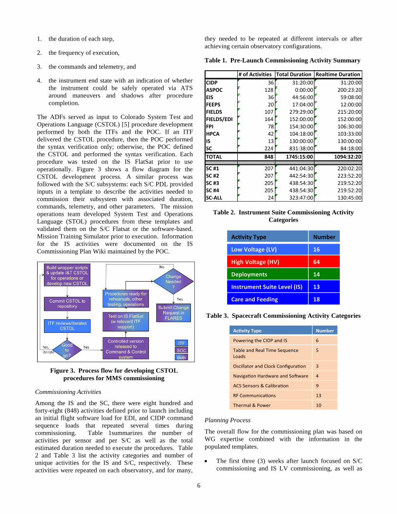
Commissioning Activities
Among the IS and the SC, there were eight hundred and
forty-eight (848) activities defined prior to launch including
an initial flight software load for EDI, and CIDP command
sequence loads that repeated several times during
commissioning. Table 1summarizes the number of
activities per sensor and per S/C as well as the total
estimated duration needed to execute the procedures. Table
2 and Table 3 list the activity categories and number of
unique activities for the IS and S/C, respectively. These
activities were repeated on each observatory, and for many,
they needed to be repeated at different intervals or after
achieving certain observatory configurations.
Table 1. Pre-Launch Commissioning Activity Summary
Table 2. Instrument Suite Commissioning Activity
Categories
Table 3. Spacecraft Commissioning Activity Categories
Planning Process
The overall flow for the commissioning plan was based on
WG expertise combined with the information in the
populated templates.
The first three (3) weeks after launch focused on S/C
commissioning and IS LV commissioning, as well as
#ofActivities TotalDuration RealtimeDuration
CIDP 36 31:20:00 31:20:00ASPOC 128 0:00:00 200:23:20EIS 36 44:56:00 59:08:00FEEPS 20 17:04:00 12:00:00FIELDS 107 279:29:00 215:20:00FIELDS/EDI 164 152:00:00 152:00:00FPI 78 154:30:00 106:30:00HPCA 42 104:18:00 103:33:00IS 13 130:00:00 130:00:00SC 224 831:38:00 84:18:00
TOTAL 848 1745:15:00 1094:32:20
SC#1 207 441:04:30 220:02:20SC#2 207 442:54:30 223:52:20SC#3 205 438:54:30 219:52:20SC#4 205 438:54:30 219:52:20SC-ALL 24 323:47:00 130:45:00
7
the early mission maneuvers to raise perigee, deploy the
magnetometer booms, and achieve the mission science
attitude spin axis target.
The following four (4) weeks focused on the SDP and
ADP boom deployments and associated spin adjustment
maneuvers, and initial HV activation.
The energy balance constraints mandated a five (5)-
week shadow season, which limited the availability of
instruments to those that needed the heat from their
operation to survive the eclipses. A primary goal was to
complete all deployments of booms and to bring up one
of each sensor on at least one S/C prior to the shadow
season to allow the science team time to evaluate data
from all of the sensors.
HV operations continued after shadow season along
with maneuvers to achieve the tetrahedral formation at
the initial scale size of 160 km.
After completing all HV Activation, the focus shifted to
the interference and cross-calibration campaigns,
followed by SITL, the Burst Data Management system,
and observatory preparations for operations.
Commissioning had to complete prior to achieving the
orbital orientation for commencing Phase 1 science
operations (apogee vector at 1800 Geocentric Solar Ecliptic
time), which occurred September 1, 2015, based on the
nominal launch date.
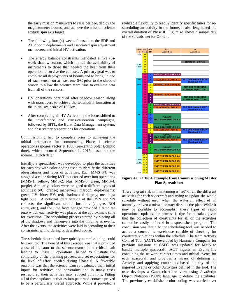
Initially, a spreadsheet was developed to plan the activities
for each day with color-coding used to identify the different
observatories and types of activities. Each MMS S/C was
assigned a color during I&T that carried over into operations
(MMS-1: yellow, MMS-2: blue, MMS-3: green, MMS-4:
purple). Similarly, colors were assigned to different types of
activities: S/C: orange; maneuvers: maroon; deployments:
green; LV: blue; HV: red; shadows: dark gray; meetings:
light blue. A notional identification of the DSN and SN
contacts, the significant orbital locations (apogee, ROI
entry, etc.), and the time from perigee provided a template
onto which each activity was placed at the approximate time
for execution. The scheduling process started by placing all
of the shadows and maneuvers into the timeline as events.
After the events, the activities were laid in according to their
constraints, with ordering as described above.
The schedule determined how quickly commissioning could
be executed. The benefit of this exercise was that it provided
a useful indicator to the science team of the critical path
leading to Phase 1 operations, helped to illustrate the
complexity of the planning process, and set expectations for
the level of effort needed during Phase 0. A favorable
outcome was that the science team re-evaluated their initial
inputs for activities and constraints and in many cases
restructured their activities into reduced durations. Fitting
all of these updated activities into patterned contacts proved
to be a particularly useful approach. While it provided a
realizable flexibility to readily identify specific times for re-
scheduling an activity in the future, it also lengthened the
overall duration of Phase 0. Figure 4a shows a sample day
of the spreadsheet for Orbit 4.
There is great risk in maintaining a ‘set’ of all the different
activities for each spacecraft and trying to update the whole
schedule without error when the waterfall effect of an
anomaly or even a missed contact disrupts the plan. While it
may be possible to accomplish these types of rapid
operational updates, the process is ripe for mistakes given
that the collection of constraints for all of the activities
cannot be easily enforced in a spreadsheet program. The
conclusion was that a better scheduling tool was needed to
act as a constraints warehouse capable of checking for
constraint violations within the schedule. The team Activity
Control Tool (tACT), developed by Hammers Company for
previous missions at GSFC, was updated for MMS to
handle multiple spacecraft. tACT ingests an Events file
containing the network contact times and orbital events for
each spacecraft and provides a means of defining an
Activity and applying constraints based on any of the
ingested Events or other Activities defined in the tool. The
user develops a Gantt chart-like view using JavaScript
Object Notation (JSON) language to define the attributes.
The previously established color-coding was carried over
Figure 1. Sample Day from Commissioning Master
Plan Spreadseheet
Orbit Hrs. S/C S/C IS
4 From ID Activities Activities
PER 0.0
0.5
1.0
1.5 SHADOW - 30 MIN5 Re 2.0
2.5 Mb 2.5
3.0
3.5
4.0 2 SPIN ADJ to 2.5RPM #24.5 2
9Re 5.0 2 CIDP_ACTUATOR_PWR #2
5.5 2
50% 6.0 1 CIDP 0002 ADP Deploy #1
6.5 1
7.0 1
7.5 1
8.0 4 CIDP 0002 ADP Deploy #4
8.5 4
9.0 4
9.5 4
10.0 3 SPIN ADJ to 2.5RPM #310.5 3 CIDP_ACTUATOR_PWR #3
11.0 3
11.5 3
AP 12.0 2
12.5 2
13.0 2
13.5 2
14.0 1
14.5 1
15.0 1 CIDP_ACTUATOR_PWR #1
15.5 1
16.0 4
16.5 4
17.0 4 CIDP_ACTUATOR_PWR #4
50% 17.5 4
18.0 3
9Re 18.5 3
19.0 3
19.5 3
20.0
20.5
2.5 Mb 21.0
5 Re 21.5
22.0
22.5
23.0
PER 23.5
FLD 002
MAG BOOM DEPLOY #4
INIT THERM CAPAC #4
INIT THERM CAPAC #3
INIT THERM CAPAC #2
INIT THERM CAPAC #1
FLD 003 Motor & HOP
Checkout #3
FLD 003 Motor & HOP
Checkout #4
FLD 002
MAG BOOM DEPLOY #2
FLD 002
MAG BOOM DEPLOY #1
FLD 003 Motor & HOP
Checkout #2
ADP 001 RECEIVING
ELEMENT DEPLOY #4
FLD 002
MAG BOOM DEPLOY #3
FLD 003 Motor & HOP
Checkout #1
ADP 001 RECEIVING
ELEMENT DEPLOY #1
Figure 4a. Orbit 4 Example from Commissioning Master
Plan Spreadsheet
8
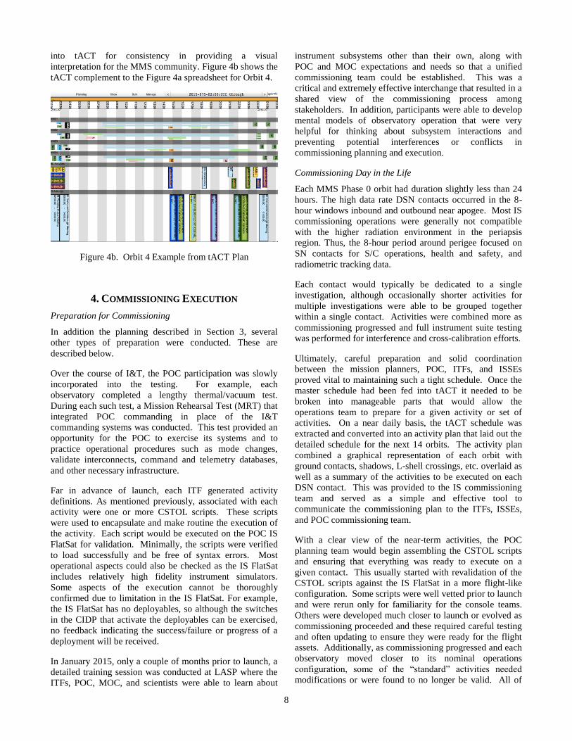
into tACT for consistency in providing a visual
interpretation for the MMS community. Figure 4b shows the
tACT complement to the Figure 4a spreadsheet for Orbit 4.
Figure 4b. Orbit 4 Example from tACT Plan
4. COMMISSIONING EXECUTION
Preparation for Commissioning
In addition the planning described in Section 3, several
other types of preparation were conducted. These are
described below.
Over the course of I&T, the POC participation was slowly
incorporated into the testing. For example, each
observatory completed a lengthy thermal/vacuum test.
During each such test, a Mission Rehearsal Test (MRT) that
integrated POC commanding in place of the I&T
commanding systems was conducted. This test provided an
opportunity for the POC to exercise its systems and to
practice operational procedures such as mode changes,
validate interconnects, command and telemetry databases,
and other necessary infrastructure.
Far in advance of launch, each ITF generated activity
definitions. As mentioned previously, associated with each
activity were one or more CSTOL scripts. These scripts
were used to encapsulate and make routine the execution of
the activity. Each script would be executed on the POC IS
FlatSat for validation. Minimally, the scripts were verified
to load successfully and be free of syntax errors. Most
operational aspects could also be checked as the IS FlatSat
includes relatively high fidelity instrument simulators.
Some aspects of the execution cannot be thoroughly
confirmed due to limitation in the IS FlatSat. For example,
the IS FlatSat has no deployables, so although the switches
in the CIDP that activate the deployables can be exercised,
no feedback indicating the success/failure or progress of a
deployment will be received.
In January 2015, only a couple of months prior to launch, a
detailed training session was conducted at LASP where the
ITFs, POC, MOC, and scientists were able to learn about
instrument subsystems other than their own, along with
POC and MOC expectations and needs so that a unified
commissioning team could be established. This was a
critical and extremely effective interchange that resulted in a
shared view of the commissioning process among
stakeholders. In addition, participants were able to develop
mental models of observatory operation that were very
helpful for thinking about subsystem interactions and
preventing potential interferences or conflicts in
commissioning planning and execution.
Commissioning Day in the Life
Each MMS Phase 0 orbit had duration slightly less than 24
hours. The high data rate DSN contacts occurred in the 8-
hour windows inbound and outbound near apogee. Most IS
commissioning operations were generally not compatible
with the higher radiation environment in the periapsis
region. Thus, the 8-hour period around perigee focused on
SN contacts for S/C operations, health and safety, and
radiometric tracking data.
Each contact would typically be dedicated to a single
investigation, although occasionally shorter activities for
multiple investigations were able to be grouped together
within a single contact. Activities were combined more as
commissioning progressed and full instrument suite testing
was performed for interference and cross-calibration efforts.
Ultimately, careful preparation and solid coordination
between the mission planners, POC, ITFs, and ISSEs
proved vital to maintaining such a tight schedule. Once the
master schedule had been fed into tACT it needed to be
broken into manageable parts that would allow the
operations team to prepare for a given activity or set of
activities. On a near daily basis, the tACT schedule was
extracted and converted into an activity plan that laid out the
detailed schedule for the next 14 orbits. The activity plan
combined a graphical representation of each orbit with
ground contacts, shadows, L-shell crossings, etc. overlaid as
well as a summary of the activities to be executed on each
DSN contact. This was provided to the IS commissioning
team and served as a simple and effective tool to
communicate the commissioning plan to the ITFs, ISSEs,
and POC commissioning team.
With a clear view of the near-term activities, the POC
planning team would begin assembling the CSTOL scripts
and ensuring that everything was ready to execute on a
given contact. This usually started with revalidation of the
CSTOL scripts against the IS FlatSat in a more flight-like
configuration. Some scripts were well vetted prior to launch
and were rerun only for familiarity for the console teams.
Others were developed much closer to launch or evolved as
commissioning proceeded and these required careful testing
and often updating to ensure they were ready for the flight
assets. Additionally, as commissioning progressed and each
observatory moved closer to its nominal operations
configuration, some of the “standard” activities needed
modifications or were found to no longer be valid. All of
9
this made pre-execution FlatSat testing a necessary and
meaningful exercise.
While having an activity definition, CSTOL scripts, and a
scheduled DSN contact were necessary prerequisites,
validating that a particular activity was ready for execution
required putting those pieces together in context. The MMS
Real Time Request (RTR) web-based form was the
repository for capturing all the information that could
impact a planned activity during the specific contact for
which it was scheduled. RTRs consisted of:
Purpose of the activity
Applicable flight rules
Notifications to be communicated to the MOC
CSTOL execution steps
Stored commands with the potential to impact the
activity
Scheduled contact information
Contingencies
ITF/ISSE/SOC approvals
Operator execution notes
This form gathered all the information applicable to a
commissioning activity in one place, allowing the POC
planning team to verify that the activity could be executed
as planned. While tACT provided orbital, environmental
and scheduling constraint checking, the tACT tool is not
able to check what is executing from stored command
sequences or what other instruments might be in an active
state during a planned activity. The POC planners were
responsible for verifying those types of restrictions and
communicated that verification in the RTR. The RTR also
summarized how to carry out any planned contingencies for
an activity, listing script names or commands the operators
might need to send in the event of a failed deployment or
anomalous behavior during an instrument checkout.
Once all testing and constraint validation was complete, the
RTR would be reviewed by the ITF, ISSE and POC FD.
The teams would vet the execution plan for an activity and
provide notes, additional contingencies, clarifications, etc.
as necessary. Once all parties were comfortable that an
RTR had captured all the necessary details they provided an
approval signature, confirming that they were in agreement
the finalized plan for a given activity.
As previously mentioned, the sheer size of the
commissioning team, as well as the geographic distance
between the teams’ “home bases” presented coordination
challenges from the start. In order to minimize these
challenges during phase 0 the POC established a planning
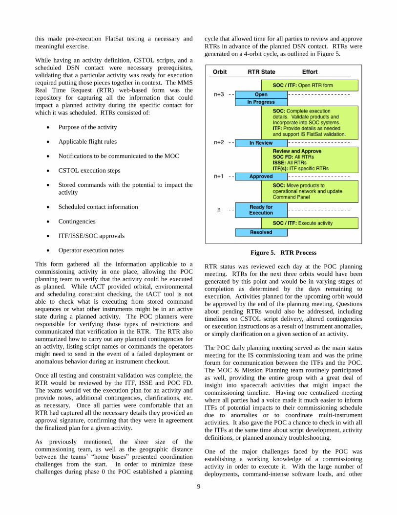
cycle that allowed time for all parties to review and approve
RTRs in advance of the planned DSN contact. RTRs were
generated on a 4-orbit cycle, as outlined in Figure 5.
Figure 5. RTR Process
RTR status was reviewed each day at the POC planning
meeting. RTRs for the next three orbits would have been
generated by this point and would be in varying stages of
completion as determined by the days remaining to
execution. Activities planned for the upcoming orbit would
be approved by the end of the planning meeting. Questions
about pending RTRs would also be addressed, including
timelines on CSTOL script delivery, altered contingencies
or execution instructions as a result of instrument anomalies,
or simply clarification on a given section of an activity.
The POC daily planning meeting served as the main status
meeting for the IS commissioning team and was the prime
forum for communication between the ITFs and the POC.
The MOC & Mission Planning team routinely participated
as well, providing the entire group with a great deal of
insight into spacecraft activities that might impact the
commissioning timeline. Having one centralized meeting
where all parties had a voice made it much easier to inform
ITFs of potential impacts to their commissioning schedule
due to anomalies or to coordinate multi-instrument
activities. It also gave the POC a chance to check in with all
the ITFs at the same time about script development, activity
definitions, or planned anomaly troubleshooting.
One of the major challenges faced by the POC was
establishing a working knowledge of a commissioning
activity in order to execute it. With the large number of
deployments, command-intense software loads, and other

10
complex commissioning activities, it was crucial that the
team performing a given activity be familiar with both its
nominal flow and how to identify and react to problems that
may arise. To that end, the first hour of each shift was spent
walking through the activities planned for the coming 12
hours. These walkthroughs were led by the POC Planner
and benefited from the participation of the on-shift ITF,
ISSE, POC FD, FC, and CC. At a minimum, walkthroughs
reviewed:
1. The CSTOL script or scripts to be executed
2. Possible contingencies and responses
3. Any limit violations expected during the activity
4. Any timing constraints or restrictions due to stored
commands executing during the contact
5. The order activities should be executed on a contact if
there was more than one
Holding these walkthroughs once per shift easily brought
the on-console team up to speed without overburdening
them with learning the minutiae of every planned
commissioning activity.
Boom deployments were deemed critical activities and as
such highly detailed walkthroughs were held for these. In
the walkthroughs, the ITFs presented technical background
on the activity and contingency flowcharts were reviewed
extensively so that the whole team knew where the potential
stopping points were. The MOC operators also participated
in these walkthroughs as there was often a good deal of
interaction between the MOC and the POC planned for the
activity. These detailed walkthroughs were held a few days
in advance when all of the crew members who would
execute them on each observatory could participate. This
also allowed the FC and CC who would be on console the
time to run through the CSTOL scripts on the flatsat before
they did it in flight. Having the entire team participate in
these walkthroughs was extremely beneficial and this
training made the entire team more knowledgeable about the
activity.
Transition to Nominal Ops
A key factor was the incremental method used to ease the
way into operations. Prior to entering the shadow season at
the end of the second month of commissioning, an FPI
activity to test an operational Orbit in the Life (OITL)
(FPI.010.2) served as the initial segue into operations,. This
was the first activity necessitating each ITF to consider
other instrument’s states and configurations and the first
point at which multiple IS activities were coordinated using
the S/C Absolute Time Sequence (ATS) mechanism.
Participation was limited, since each sensor had not been
fully activated and calibrated at that time. After executing
FPI.010.2 the first time on MMS3, a target of opportunity
arose during the shadow season when MMS aligned with
the Van Allen Probes (VAP); this again brought the multi-
discipline IS team together to execute for common science
goals. Given the power limitations due to a long shadow
period immediately preceding, the VAP Alignment was a
limited case involving only two (2) spacecraft and a subset
of instruments.
Following the post-shadow season, the pressing need to
bring one (1) observatory to full operational readiness drove
the planning. Once each sensor was activated at full level on
MMS-1, FPI.010.2 was executed via ATS, followed by full-
time pseudo-nominal operations. Pseudo-nominal referred
to the fact that interference observations were still possible
and the SITL process, while not in full operation, was able
to be integrated in gracefully incremented steps. Each
successive observatory was brought up in that manner, and
the SITL process evolved, preparing for the four (4)
observatory fleet.
With four (4) observatory SITL processing underway, the
team was able to execute specialized tests for cross-
calibration and interference identification. Following this
cross-calibration campaign, the fleet went into full SITL
operations, allowing the complete science team to
participate and to debug the SITL process (which is
intended to enable quick turn-around on science meta-data
evaluation and to guide the science selections in the ROI of
the previous orbit.) The science team also spent the last two
(2) weeks prior to the transition to Phase 1 preparing their
instruments by generating final software loads and tuning
parameters. In this manner, the operational paradigm grew
incrementally over the last several months of
commissioning, providing science team engagement and
education in preparation for Phase 1 operations.
Towards the end of commissioning a transitional period was
planned to hand over day-to-day operations from the ITFs
and ISSEs to the POC. Although the ITFs continued to
participate by defining activity requests, many of these
requests became sufficiently repetitive that they no longer
required ITF participation in their execution. In contrast,
major activities such as updates to flight software or
operational configurations continue to include ITF
participation.
One significant exception to ITF operation is the routine
update of CIDP command sequences. The CIDP includes a
capability for instruments to define command sequences that
can be executed on board. CIDP command sequence updates
will be required routinely (about monthly) throughout the
mission. This would represent a significant cost burden if
the ITFs, ISSEs, CIDP, and POC personnel were all
required.
To minimize this involvement, a variety of tools were
created to ease the operational burden on the POC such that
participation from non-POC personnel was eliminated from
most of the command sequence update process. The
definition of command sequence updates are prepared by
the ITFs and provided to the POC. The CIDP ITF produced
11
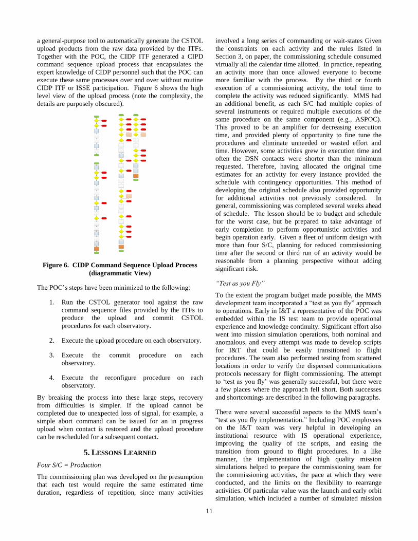
a general-purpose tool to automatically generate the CSTOL
upload products from the raw data provided by the ITFs.
Together with the POC, the CIDP ITF generated a CIPD
command sequence upload process that encapsulates the
expert knowledge of CIDP personnel such that the POC can
execute these same processes over and over without routine
CIDP ITF or ISSE participation. Figure 6 shows the high
level view of the upload process (note the complexity, the
details are purposely obscured).
Figure 6. CIDP Command Sequence Upload Process
(diagrammatic View)
The POC’s steps have been minimized to the following:
1. Run the CSTOL generator tool against the raw
command sequence files provided by the ITFs to
produce the upload and commit CSTOL
procedures for each observatory.
2. Execute the upload procedure on each observatory.
3. Execute the commit procedure on each
observatory.
4. Execute the reconfigure procedure on each
observatory.
By breaking the process into these large steps, recovery
from difficulties is simpler. If the upload cannot be
completed due to unexpected loss of signal, for example, a
simple abort command can be issued for an in progress
upload when contact is restored and the upload procedure
can be rescheduled for a subsequent contact.
5. LESSONS LEARNED
Four S/C = Production
The commissioning plan was developed on the presumption
that each test would require the same estimated time
duration, regardless of repetition, since many activities
involved a long series of commanding or wait-states Given
the constraints on each activity and the rules listed in
Section 3, on paper, the commissioning schedule consumed
virtually all the calendar time allotted. In practice, repeating
an activity more than once allowed everyone to become
more familiar with the process. By the third or fourth
execution of a commissioning activity, the total time to
complete the activity was reduced significantly. MMS had
an additional benefit, as each S/C had multiple copies of
several instruments or required multiple executions of the
same procedure on the same component (e.g., ASPOC).
This proved to be an amplifier for decreasing execution
time, and provided plenty of opportunity to fine tune the
procedures and eliminate unneeded or wasted effort and
time. However, some activities grew in execution time and
often the DSN contacts were shorter than the minimum
requested. Therefore, having allocated the original time
estimates for an activity for every instance provided the
schedule with contingency opportunities. This method of
developing the original schedule also provided opportunity
for additional activities not previously considered. In
general, commissioning was completed several weeks ahead
of schedule. The lesson should be to budget and schedule
for the worst case, but be prepared to take advantage of
early completion to perform opportunistic activities and
begin operation early. Given a fleet of uniform design with
more than four S/C, planning for reduced commissioning
time after the second or third run of an activity would be
reasonable from a planning perspective without adding
significant risk.
“Test as you Fly”
To the extent the program budget made possible, the MMS
development team incorporated a “test as you fly” approach
to operations. Early in I&T a representative of the POC was
embedded within the IS test team to provide operational
experience and knowledge continuity. Significant effort also
went into mission simulation operations, both nominal and
anomalous, and every attempt was made to develop scripts
for I&T that could be easily transitioned to flight
procedures. The team also performed testing from scattered
locations in order to verify the dispersed communications
protocols necessary for flight commissioning. The attempt
to ‘test as you fly’ was generally successful, but there were
a few places where the approach fell short. Both successes
and shortcomings are described in the following paragraphs.
There were several successful aspects to the MMS team’s
“test as you fly implementation.” Including POC employees
on the I&T team was very helpful in developing an
institutional resource with IS operational experience,
improving the quality of the scripts, and easing the
transition from ground to flight procedures. In a like
manner, the implementation of high quality mission
simulations helped to prepare the commissioning team for
the commissioning activities, the pace at which they were
conducted, and the limits on the flexibility to rearrange
activities. Of particular value was the launch and early orbit
simulation, which included a number of simulated mission
12
anomalies. This simulation gave a realistic appreciation of
the “feel” of flight and allowed the teams to test their
approach to anomaly resolution, resulting in useful changes
to procedures as well as a more successful commissioning
activity. The commissioning phase of the mission was
materially improved by these aspects of “test as you fly”
ground operations.
There were several areas in which the “test as you fly”
preparation was inadequate. The most serious from a
budget/schedule standpoint was the amount of effort
necessary to translate ground scripts into flight procedures.
The ITF I&T effort used a ground software system called
Ground Support Equipment Operating System (GSEOS),
while the flight operational ground systems are the
Operations and Science Instrument Support Command and
Control (OASIS-CC) at the POC and the Advanced
Spacecraft Integration and System Test (ASIST) at the
MOC, which uses STOL. Addressing the differences
between these ground and test systems had a non-zero cost.
Both ground systems used by the instrument suite
implemented a CSTOL variant, with the GSEOS
implementation reasonably close to that of OASIS-CC.
However, many of the I&T scripts for the IS had not been
structured in a way that met flight operational coding
standards. This required that the I&T scripts be rewritten
for use in a flight environment. The lesson learned is that, if
at all possible, the I&T development should use the flight
command and telemetry (C&T) system as well as flight
coding approaches. Even if a common C&T system is not
used, a flight-centric coding standard should be established
and followed prior to beginning I&T, and I&T work
products destined for operations should be reviewed by
operations personnel as part of the routine development
process for I&T. If this is not done, then extra work will be
required to transition I&T scripts to flight.
The most serious area of “test as you fly” shortcomings
from a technical standpoint was the inability to reproduce
the CFDP response delays inherent in operation with DSN
and the ground station. During I&T, the CFDP files were
closed generally within a 20-40 seconds. In flight, they
would remain open 3-10 minutes (not seen in ground
testing) and this resulted in a number of operational
challenges including unexpectedly high processor usage,
delays in data transmission, and increasingly complicated
ground based data management. The operational difficulties
eventually culminated in a new software load. The lesson
learned was to ensure that future ground systems
incorporate timing based upon flight norms.
The final “test as you fly” lesson exposed shortcomings
found in the configuration of the mission “FlatSats”. There
are three FlatSats available for mission use, one at
NASA/GSFC, a second at CU/LASP, and a third more
limited test bed for CIDP-centric testing. The NASA/GSFC
FlatSat has a complete S/C bus configuration including a
communication card along with an engineering model (EM)
CIDP and FPI IDPU (central processing unit) that connects
to a ground segment telemetry system equivalent to the
operational one, particularly as regards CFDP
processing. However, instruments are computer-based
simulations with moderate to low fidelity; they produce an
appropriate volume of data, but the data lacks the
periodicity, size, and internal structure of instrument
produced data. The CU/LASP FlatSat has no S/C hardware
but has an EM CIDP and a complete set of IS hardware with
medium to high fidelity. These instrument simulators
typically run their flight software, and thus produce data of
much higher correspondence to operation, although a robust
science simulation mechanism is typically not
included. The software test bed for the IS consists of an EM
CIDP and a special test equipment (STE) that simulates the
instruments, S/C, and ground segment. Thus, there is no
end-to-end, full fidelity FlatSat available. As a result, we
must deal with a variety of “exceptions” when we test
scripts, and are unable to fully ground test some aspects of
system operation. The lesson learned is to generate a fully
capable, high fidelity FlatSat for mission use.
Complexity vs. Flexibility
Commissioning a science observatory with one or two
instruments is a complex and intricate task. Multiplying the
number of observatories by four, and the number of
instruments by 10, gave MMS a level of complexity that
had to be offset by other factors in order to commission
successfully. The primary offsetting factor for MMS was
flexibility: There were times when MMS had adequate
flexibility resulting in simplification and efficiency; there
were other times where the lack of flexibility resulted in
significant inefficiency; and there were times when no
amount of flexibility could have made it easier.
One area of great flexibility was provided by MMS
instrument specific command panels. These command
panels included a set of pre-defined and pre-validated
operational procedures that were developed during the
planning phase and expanded as the mission progressed to
incorporated lessons learned. While most operational
sequences were created uniquely and vetted well in advance
(24 hours or more) of an observatory contact, there were
occasions when quick changes were required (often within a
contact.) The existence of the instrument command panels
allowed quick processing of operational sequence changes,
or entirely new sequences that could invoke the existing
procedures found in the control panels. The flexibility
provided by the captured operational experience contained
in those panels thus mitigated the complexity of late
breaking changes, minimizing impacts to the overall
commissioning schedule.
The as-developed commissioning plan had a high level of
complex integration. As long as all of the operations went
well, and all of the development efforts for the succeeding
operations were on time, the system worked. However, the
complexity left no room for error. As expected, there were
times when instrument anomalies or missed passes resulted
in the need to rearrange the sequence of operations. Some
13
rearrangement was as simple as swapping a sequence of
operations between two observatories. Inevitably however,
there were times when a RF contact could not be used for
commissioning activity, either because of strict sequencing
constraints or because a substitute procedure had not been
developed. If a set of completed procedures had been ready
for execution, and if the execution sequence order could
have been made more flexible, a more efficient use of RF
time could have been achieved. This is an example of a case
where no compensating flexibility was available to offset
the mission complexity. Fortunately, there was enough extra
time in the commissioning schedule that the complexity
caused no ultimate problem.
The MMS commissioning team discovered how truly
complex MMS operations could be when a science
opportunity arose towards the end of the eclipse season for a
coordinated observing campaign with the Van Allen probe
mission. (This opportunity was not included in the baseline
commissioning plan.) It took a great deal of planning,
procedure development, and engineering calculation to
implement the joint campaign while ensuring that all of the
instruments on the two observatories involved were ready to
take quality science data and that the power margins were
adequate. It also required developing the appropriate
absolute time sequence (ATS) uploads on relatively short
notice. The sheer complexity of the job, occurring relatively
early in the mission, resulted in an extremely difficult period
of effort for the POC, MOC, ITF, and ISSEs. The lesson is
that, sometimes, operating a complex mission is going to be
difficult no matter what compensating provisions are
included.
Commissioning Team Shift Scheduling
Because the average length of an MMS orbit during Phase 0
was just under 24 hours, the commissioning teams had to
choose between a shift schedule that followed a 24 hour day
or one that defined the orbit as the standard day. Following
a 24-hour day allowed crews a routine that they could plan
for consistently throughout commissioning. The day shift
crew could maintain a normal sleep-wake schedule and
continue to interact with others in their organization during
standard business hours. The night shift could adapt to a set
of core work hours that wouldn’t change over the course of
the 6-month commissioning phase. Defining a day to
follow the length of an orbit required crews to shift their
sleep-wake times routinely and could cause confusion as to
when shifts started on “transition” days. However there
were clear benefits to activity execution in this mode.
The observatory commissioning team kept their shift times
consistent throughout all of Phase 0. Although maneuvers
required a small crew to support at any time of day or night,
planning activities and Command Authorization Meetings
(CAM) were performed during local day shift. Similarly,
S/C bus activities occurred at any time, were often passive
activities, included little real time commanding, and were
subject to offline data analysis. Because of this, there was
no driving need for the observatory crew to follow the orbit.
The POC’s decision to align crew shifts with the MMS orbit
provided significant benefits to the IS commissioning plan
with minimal impact to the crews themselves. While this
approach was more challenging to the humans on shift the
benefits to the overall commissioning flow far outweighed
the inconveniences. The POC shift handovers occurred near
perigee and apogee each orbit. Because of the ground
contact schedule and the need to execute the majority of the
IS commissioning activities over DSN sites, this schedule
guaranteed that one handover per day would occur during a
quiet part of the orbit. The POC understood that, with the
command intense activities planned for all instruments,
trying to fit in a handover briefing while executing a
realtime activity would introduce many opportunities for
error. The added distraction of translating a large amount of
information to an incoming crew member could easily cause
mistakes in communication on console or the overlooking of
anomalous indications in telemetry.
Organizing crew shifts to follow the orbit allowed the POC
to take full advantage of the gap in DSN contacts during that
part of the orbit. Without DSN contacts to execute
commissioning activities the POC, ITFs and ISSEs were not
needed on console. The ISSEs also realized the advantages
of this schedule and aligned their shift splits with
apogee/perigee as well. This provided the ideal time to
schedule the daily IS planning meeting and activity
walkthroughs and ensured that all teams were able to
participate. This did present some difficulties coordinating
with the MOC mission planners as there was a great deal of
overlap between the observatory Tactical and IS Planning
meetings. ITFs and ISSEs were often on console during
these meetings and couldn’t always participate as fully as
they wanted to. To bridge this gap one member of the POC
planning team would attend the observatory Tactical
meeting and serve as the voice of the IS when needed. As
the local time of perigee evolved, the time of the POC
Planning meeting and the Tactical Planning meeting began
to align and the commissioning team combined these two
meetings starting after the shadow season. This did still
present attendance problems at times, but since the
commissioning schedule post-shadow was more relaxed it
was less of an issue to work around.
6. CONCLUSIONS
MMS was a complex and challenging mission to
commission. With careful attention to detail in the
commissioning planning process complex, multi-
observatory missions can be successfully commissioned on
schedule and within budget. To date, MMS successfully
completed the variations in formation separation over the
first two months of Phase 1A, settling on separation scale
sizing for the remainder of the Phase. The mission continues
to provide remarkable science results and has not
encountered any major anomalies among the fleet.
14
ACKNOWLEDGEMENTS
The authors wish to thank NASA Goddard for the
opportunity to build this exciting fleet of observatories. We
would also like to thank the entire MMS team involved in
commissioning for their hard work and dedication that made
MMS commissioning so successful and gave us many
experiences we wanted to share. Finally, we would like to
thank Martin Wasiewicz for his careful review of this paper.
REFERENCES
[1] Zell, Holly, Ed. Magnetospheric Multiscale. Oct. 18,
2015. Web. Oct. 20, 2015.
http://www.nasa.gov/mission_pages/mms/index.html
[1] J.L. Burch, R.B. Torbert. The Magnetospheric Multiscale
(MMS) Mission, Preface, Space Science Reviews
(online), p. 1.
[2] J.L. Burch, T.E. Moore, R.B. Torbert, B.L. Giles.
Magnetospheric Multiscale Overview and Science
Objectives, Space Science Reviews (online), p. 2.
[3] Burch and Torbert, p.1.
[4] Burch, Moore, Torbert, and Giles, pp. 9-10
[5] LASP. CSTOL Reference Manual. Version 1.0. January
11, 2010.
[6] GSE Software, Inc. GSEOS 6.0 User Manual. GSE
Software, Inc. 1998-2012. PDF file.
[7] Fung, Edwin, Ed. “Advanced Spacecraft Integration &
System Test Software (ASIST)”. ASIST HOME. April 9,
2012. NASA. Web. Oct. 20, 2015. https://nasa-
asist.gsfc.nasa.gov/index.html.
15
BIOGRAPHY
Paul Wood received a B.S. in
Mathematics, Computer Science, and
Systems Design from University of Texas
at San Antonio, in 1979 and an M.S. from
Purdue University in computer science in
1983. He has been with Southwest
Research Institute for more than 30 years.
He is the software lead for the MMS HPCA instrument,
software lead for the MMS CIDP for the last two years, and
is one of the IS systems engineers for MMS. A staff analyst
with SwRI, he worked on the flight software for the Swift X-
Ray Telescope and on various programs including robotics
and telecommunications systems.
John Stone received a B.S. in
Engineering Science (computer
engineering concentration) from Trinity
University in San Antonio and an M.S.E.
with a concentration in Electrical
Engineering at the University of Texas at
Austin. He is the payload electrical
systems engineer for MMS and is
currently an Institute Engineer and chief engineer of the
Space Systems Directorate at Southwest Research Institute
(SwRI.) He has worked at SwRI for 28 years and has broad
experience in architecting, designing, building, testing, and
operating space-flight data systems and instruments.
Patrick Smith received a B.S/M.S. in
Aerospace Engineering from the University
of Colorado in 2005. He has been working
with the Mission Operations and Data
Systems group at the Laboratory for
Atmospheric Space Physics (LASP) for 10
years, giving him the opportunity to
support operations on many programs,
including SNOE, QuikSCAT, ICESat,
SORCE, AIM, SDO EVE, and GOES-R EXIS. He has
worked as the ICESat Flight Dynamics System Operations
and Planning lead and was the MMS IS Commissioning
Lead. He is currently working as the MMS POC Flight
Director.
Jennifer Reiter received a B.S. in
Engineering Physics from the Colorado
School of Mines. She has been with the
Mission Operations and Data Systems
group at Laboratory for Atmospheric and
Space Physics for 8.5 years and previously
worked in Integration and Test at
Lockheed Martin Space Systems. She has
worked as an operator and planner for the ICESat,
QuikSCAT, SORCE, AIM, Kepler, and MMS missions at
LASP and is the Lead Trainer for LASP’s Mission
Operations group. Jennifer is currently part of the POC
Planning team for MMS.
Cheryl Gramling received a B.S. in
Aerospace Engineering from
University of Maryland, currently with
over 30 years at NASA/Goddard Space
Flight Center. She was the flight
dynamics lead for MMS until 2010
when she became the Commissioning
Lead. She has served as the
navigation and mission design lead for several missions and
is currently the Center’s Senior Navigation Systems engineer
working on advanced onboard navigation and
communication systems