Commissioning and Installation Guide...MAXPRO VMS R300 Viewer Edition Commissioning and Installation...
80
Document 800-11111 – Rev A – 02/2012 MAXPRO ® VMS R300 Viewer Edition Commissioning and Installation Guide
Transcript of Commissioning and Installation Guide...MAXPRO VMS R300 Viewer Edition Commissioning and Installation...

Document 800-11111 – Rev A – 02/2012
MAXPRO® VMS R300 Viewer Edition
Commissioning and Installation Guide


Revisions
Issue Date Description
1.0 February 24, 2012 New document

M A X P R O V M S R 3 0 0 V I EW E R ED I T I O N
Table of Contents
1
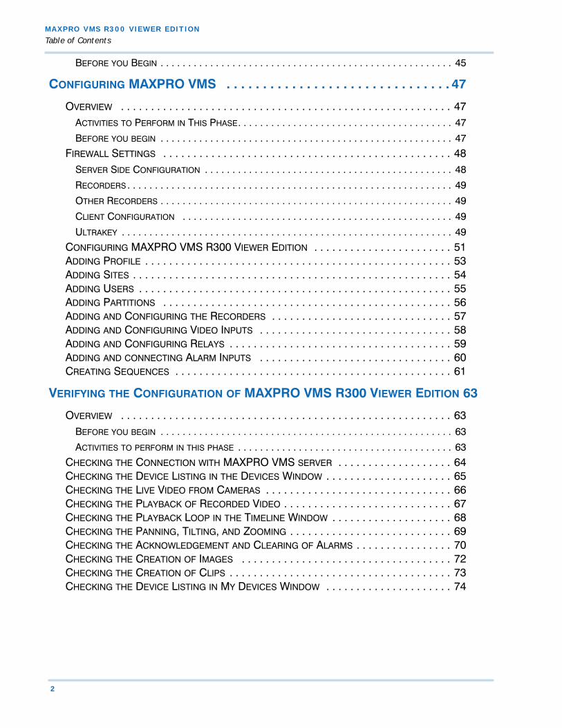
Table of Contents
ABOUT THIS GUIDE . . . . . . . . . . . . . . . . . . . . . . . . . . . . . . . . . . . . . . . . .3
INTRODUCING MAXPRO® VMS R300 VIEWER EDITION . . . . . . . . . . . . . . . . . . . . . . . .3SCOPE . . . . . . . . . . . . . . . . . . . . . . . . . . . . . . . . . . . . . . . . . . . . . . . . . . . . . . . . . . .3INTENDED AUDIENCE . . . . . . . . . . . . . . . . . . . . . . . . . . . . . . . . . . . . . . . . . . . . . . . . .4INSTALLATION AND COMMISSIONING GUIDE STRUCTURE . . . . . . . . . . . . . . . . . . . . . . . .4TYPOGRAPHICAL CONVENTIONS . . . . . . . . . . . . . . . . . . . . . . . . . . . . . . . . . . . . . . . . .4
COMMISSIONING PLAN . . . . . . . . . . . . . . . . . . . . . . . . . . . . . . . . . . . . . . .5
OVERVIEW . . . . . . . . . . . . . . . . . . . . . . . . . . . . . . . . . . . . . . . . . . . . . . . . . . . . . . . . .5STEPS IN THE COMMISSIONING PROCESS . . . . . . . . . . . . . . . . . . . . . . . . . . . . . . . . . . .5
SETTING UP THE MAXPRO VMS SERVER AND CLIENT COMPUTERS . . . . . . . . . . . . . . . . . . . 5
INSTALLING THE MAXPRO VMS SOFTWARE . . . . . . . . . . . . . . . . . . . . . . . . . . . . . . . . . . . . 5
CONFIGURING THE MAXPRO VMS SYSTEM. . . . . . . . . . . . . . . . . . . . . . . . . . . . . . . . . . . . . 6
VERIFYING THE CONFIGURATION . . . . . . . . . . . . . . . . . . . . . . . . . . . . . . . . . . . . . . . . . . . . . 6
SETTING UP THE CLIENT AND THE SERVER COMPUTER . . . . . . . . . . . . . . .9
OVERVIEW . . . . . . . . . . . . . . . . . . . . . . . . . . . . . . . . . . . . . . . . . . . . . . . . . . . . . . . . .9BEFORE YOU BEGIN. . . . . . . . . . . . . . . . . . . . . . . . . . . . . . . . . . . . . . . . . . . . . . . . . . . . . . . 9
ACTIVITIES TO PERFORM IN THIS PHASE . . . . . . . . . . . . . . . . . . . . . . . . . . . . . . . . . . . . . . . . 9
HARDWARE SPECIFICATIONS . . . . . . . . . . . . . . . . . . . . . . . . . . . . . . . . . . . . . . . . . . .10CONNECTING THE MONITORS . . . . . . . . . . . . . . . . . . . . . . . . . . . . . . . . . . . . . . . . . .12
CONFIGURING THE MONITOR DISPLAY PROPERTIES. . . . . . . . . . . . . . . . . . . . . . . . . . . . . . . 12
INSTALLING THE MAXPRO VMS SOFTWARE . . . . . . . . . . . . . . . . . . . . .13
OVERVIEW . . . . . . . . . . . . . . . . . . . . . . . . . . . . . . . . . . . . . . . . . . . . . . . . . . . . . . . .13BEFORE YOU BEGIN. . . . . . . . . . . . . . . . . . . . . . . . . . . . . . . . . . . . . . . . . . . . . . . . . . . . . . 13
SYSTEM REQUIREMENTS . . . . . . . . . . . . . . . . . . . . . . . . . . . . . . . . . . . . . . . . . . . . . . . . . . 13
INSTALLING THE MAXPRO VMS SOFTWARE . . . . . . . . . . . . . . . . . . . . . . . . . . . . . . .14HOW TO INSTALL MAXPRO VMS SOFTWARE . . . . . . . . . . . . . . . . . . . . . . . . . . . . . .15FULL INSTALLATION . . . . . . . . . . . . . . . . . . . . . . . . . . . . . . . . . . . . . . . . . . . . . . . . .19CLIENT ONLY INSTALLATION . . . . . . . . . . . . . . . . . . . . . . . . . . . . . . . . . . . . . . . . . . .33
AFTER INSTALLING MAXPRO VMS R300 VIEWER EDITION . . . . . . . . . . . . . . . . . . . . . . . . . 37
REMOVING MAXPRO VMS R300 . . . . . . . . . . . . . . . . . . . . . . . . . . . . . . . . . . . . . . .38BEFORE YOU BEGIN. . . . . . . . . . . . . . . . . . . . . . . . . . . . . . . . . . . . . . . . . . . . . . . . . . . . . . 38
AFTER REMOVING MAXPRO VMS . . . . . . . . . . . . . . . . . . . . . . . . . . . . . . . . . . . . . . . . . . . 42
UPGRADING TO MAXPRO VMS R300 . . . . . . . . . . . . . . . . . . . . . . . . . . . . . . . . . . .44OVERVIEW . . . . . . . . . . . . . . . . . . . . . . . . . . . . . . . . . . . . . . . . . . . . . . . . . . . . . . . . . . . . 44
BEFORE YOU BEGIN. . . . . . . . . . . . . . . . . . . . . . . . . . . . . . . . . . . . . . . . . . . . . . . . . . . . . . 44
UPGRADING MAXPRO VMS R300 VIEWER EDITION . . . . . . . . . . . . . . . . . . . . . . . . .45
M A X P R O V M S R 3 0 0 V I E W ER E D I T I O N
Table of Contents
2
BEFORE YOU BEGIN . . . . . . . . . . . . . . . . . . . . . . . . . . . . . . . . . . . . . . . . . . . . . . . . . . . . . 45
CONFIGURING MAXPRO VMS . . . . . . . . . . . . . . . . . . . . . . . . . . . . . . . 47
OVERVIEW . . . . . . . . . . . . . . . . . . . . . . . . . . . . . . . . . . . . . . . . . . . . . . . . . . . . . . . 47ACTIVITIES TO PERFORM IN THIS PHASE. . . . . . . . . . . . . . . . . . . . . . . . . . . . . . . . . . . . . . . 47
BEFORE YOU BEGIN . . . . . . . . . . . . . . . . . . . . . . . . . . . . . . . . . . . . . . . . . . . . . . . . . . . . . 47
FIREWALL SETTINGS . . . . . . . . . . . . . . . . . . . . . . . . . . . . . . . . . . . . . . . . . . . . . . . . 48SERVER SIDE CONFIGURATION . . . . . . . . . . . . . . . . . . . . . . . . . . . . . . . . . . . . . . . . . . . . . 48
RECORDERS . . . . . . . . . . . . . . . . . . . . . . . . . . . . . . . . . . . . . . . . . . . . . . . . . . . . . . . . . . . 49
OTHER RECORDERS . . . . . . . . . . . . . . . . . . . . . . . . . . . . . . . . . . . . . . . . . . . . . . . . . . . . . 49
CLIENT CONFIGURATION . . . . . . . . . . . . . . . . . . . . . . . . . . . . . . . . . . . . . . . . . . . . . . . . . 49
ULTRAKEY . . . . . . . . . . . . . . . . . . . . . . . . . . . . . . . . . . . . . . . . . . . . . . . . . . . . . . . . . . . . 49
CONFIGURING MAXPRO VMS R300 VIEWER EDITION . . . . . . . . . . . . . . . . . . . . . . . 51ADDING PROFILE . . . . . . . . . . . . . . . . . . . . . . . . . . . . . . . . . . . . . . . . . . . . . . . . . . . 53ADDING SITES . . . . . . . . . . . . . . . . . . . . . . . . . . . . . . . . . . . . . . . . . . . . . . . . . . . . . 54ADDING USERS . . . . . . . . . . . . . . . . . . . . . . . . . . . . . . . . . . . . . . . . . . . . . . . . . . . . 55ADDING PARTITIONS . . . . . . . . . . . . . . . . . . . . . . . . . . . . . . . . . . . . . . . . . . . . . . . . 56ADDING AND CONFIGURING THE RECORDERS . . . . . . . . . . . . . . . . . . . . . . . . . . . . . . 57ADDING AND CONFIGURING VIDEO INPUTS . . . . . . . . . . . . . . . . . . . . . . . . . . . . . . . . 58ADDING AND CONFIGURING RELAYS . . . . . . . . . . . . . . . . . . . . . . . . . . . . . . . . . . . . . 59ADDING AND CONNECTING ALARM INPUTS . . . . . . . . . . . . . . . . . . . . . . . . . . . . . . . . 60CREATING SEQUENCES . . . . . . . . . . . . . . . . . . . . . . . . . . . . . . . . . . . . . . . . . . . . . . 61
VERIFYING THE CONFIGURATION OF MAXPRO VMS R300 VIEWER EDITION 63
OVERVIEW . . . . . . . . . . . . . . . . . . . . . . . . . . . . . . . . . . . . . . . . . . . . . . . . . . . . . . . 63BEFORE YOU BEGIN . . . . . . . . . . . . . . . . . . . . . . . . . . . . . . . . . . . . . . . . . . . . . . . . . . . . . 63
ACTIVITIES TO PERFORM IN THIS PHASE . . . . . . . . . . . . . . . . . . . . . . . . . . . . . . . . . . . . . . . 63
CHECKING THE CONNECTION WITH MAXPRO VMS SERVER . . . . . . . . . . . . . . . . . . . 64CHECKING THE DEVICE LISTING IN THE DEVICES WINDOW . . . . . . . . . . . . . . . . . . . . . 65CHECKING THE LIVE VIDEO FROM CAMERAS . . . . . . . . . . . . . . . . . . . . . . . . . . . . . . . 66CHECKING THE PLAYBACK OF RECORDED VIDEO . . . . . . . . . . . . . . . . . . . . . . . . . . . . 67CHECKING THE PLAYBACK LOOP IN THE TIMELINE WINDOW . . . . . . . . . . . . . . . . . . . . 68CHECKING THE PANNING, TILTING, AND ZOOMING . . . . . . . . . . . . . . . . . . . . . . . . . . . 69CHECKING THE ACKNOWLEDGEMENT AND CLEARING OF ALARMS . . . . . . . . . . . . . . . . 70CHECKING THE CREATION OF IMAGES . . . . . . . . . . . . . . . . . . . . . . . . . . . . . . . . . . . 72CHECKING THE CREATION OF CLIPS . . . . . . . . . . . . . . . . . . . . . . . . . . . . . . . . . . . . . 73CHECKING THE DEVICE LISTING IN MY DEVICES WINDOW . . . . . . . . . . . . . . . . . . . . . 74
MAXPRO VMS R300 Viewer Edition Commissioning and Installation Guide 3
. . . . .
. . . . . . . . . . . . . . . . . . . . . . . . . . . . . . . . . . .ABOUT THIS GUIDE
INTRODUCING MAXPRO® VMS R300 VIEWER
. . . . . . . . . . . . . . . . . . . . . . . . . . . . . . . . . . . . . . . . . . . . . . . . . . . . . . . . . . .EDITION
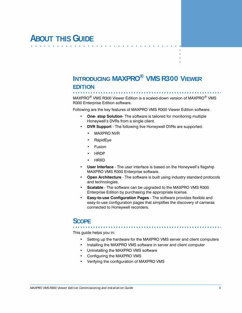
MAXPRO® VMS R300 Viewer Edition is a scaled-down version of MAXPRO® VMS R300 Enterprise Edition software.
Following are the key features of MAXPRO VMS R300 Viewer Edition software.
• One- stop Solution- The software is tailored for monitoring multiple Honeywell’s DVRs from a single client.
• DVR Support - The following five Honeywell DVRs are supported.
• MAXPRO NVR
• RapidEye
• Fusion
• HRDP
• HRXD
• User Interface - The user interface is based on the Honeywell’s flagship MAXPRO VMS R300 Enterprise software.
• Open Architecture - The software is built using industry standard protocols and technologies.
• Scalable - The software can be upgraded to the MAXPRO VMS R300 Enterprise Edition by purchasing the appropriate license.
• Easy-to-use Configuration Pages - The software provides flexible and easy-to-use configuration pages that simplifies the discovery of cameras connected to Honeywell recorders.
. . . . . . . . . . . . . . . . . . . . . . . . . . . . . . . . . . . . . . . . . . . . . . . . . . . . . . . . . . .SCOPE
This guide helps you in:
• Setting up the hardware for the MAXPRO VMS server and client computers• Installing the MAXPRO VMS software in server and client computer• Uninstalling the MAXPRO VMS software• Configuring the MAXPRO VMS• Verifying the configuration of MAXPRO VMS
AB OU T TH I S G U IDE
Intended Audience
4 MAXPRO VMS R300 Viewer Edition Commissioning and Installation Guide
. . . . . . . . . . . . . . . . . . . . . . . . . . . . . . . . . . . . . . . . . . . . . . . . . . . . . . . . . . .INTENDED AUDIENCE
This guide is intended for the field and commissioning engineers of MAXPRO VMS.
INSTALLATION AND COMMISSIONING GUIDE
. . . . . . . . . . . . . . . . . . . . . . . . . . . . . . . . . . . . . . . . . . . . . . . . . . . . . . . . . . .STRUCTURE
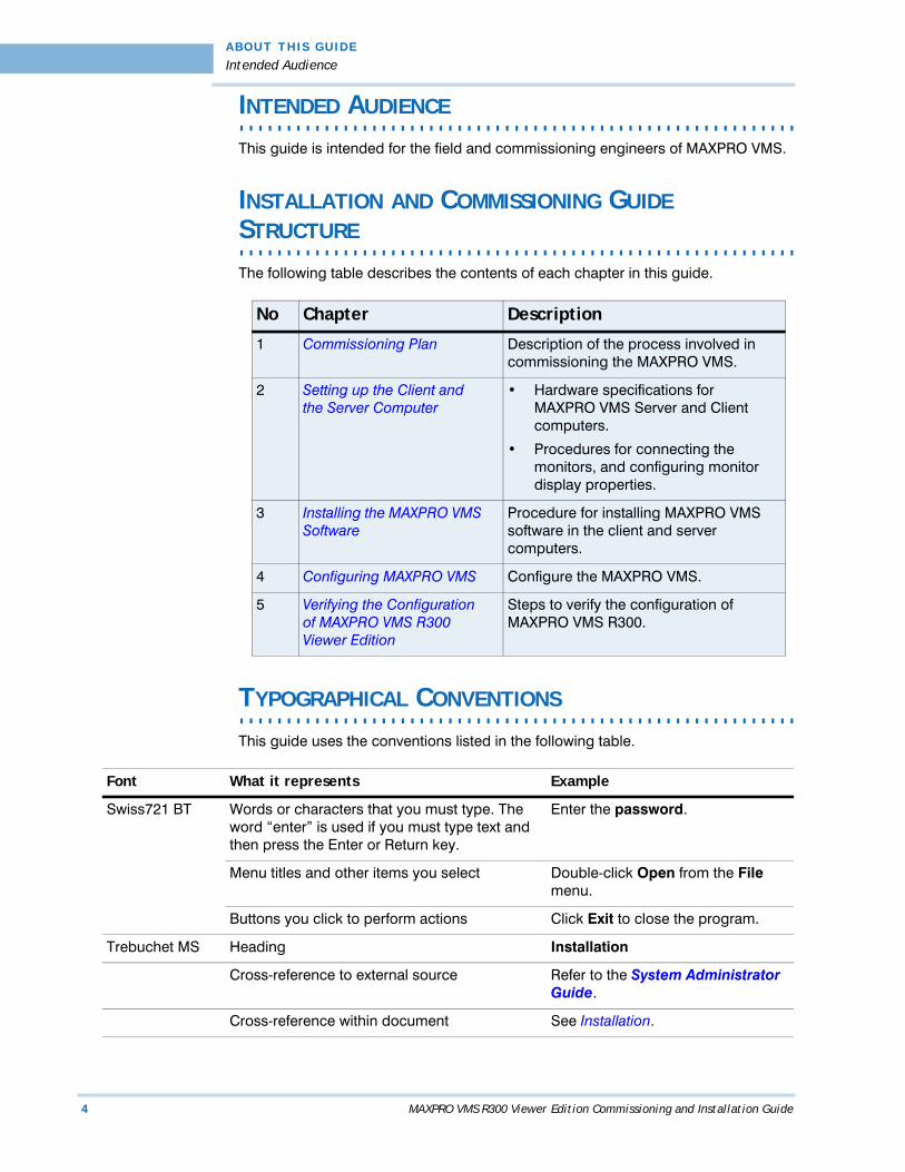
The following table describes the contents of each chapter in this guide.
. . . . . . . . . . . . . . . . . . . . . . . . . . . . . . . . . . . . . . . . . . . . . . . . . . . . . . . . . . .TYPOGRAPHICAL CONVENTIONS
This guide uses the conventions listed in the following table.
No Chapter Description
1 Commissioning Plan Description of the process involved in commissioning the MAXPRO VMS.
2 Setting up the Client and the Server Computer
• Hardware specifications for MAXPRO VMS Server and Client computers.
• Procedures for connecting the monitors, and configuring monitor display properties.
3 Installing the MAXPRO VMS Software
Procedure for installing MAXPRO VMS software in the client and server computers.
4 Configuring MAXPRO VMS Configure the MAXPRO VMS.
5 Verifying the Configuration of MAXPRO VMS R300 Viewer Edition
Steps to verify the configuration of MAXPRO VMS R300.
Font What it represents Example
Swiss721 BT Words or characters that you must type. The word “enter” is used if you must type text and then press the Enter or Return key.
Enter the password.
Menu titles and other items you select Double-click Open from the File menu.
Buttons you click to perform actions Click Exit to close the program.
Trebuchet MS Heading Installation
Cross-reference to external source Refer to the System Administrator Guide.
Cross-reference within document See Installation.
MAXPRO VMS R300 Viewer Edition Commissioning and Installation Guide 5
1. . . . .
. . . . . . . . . . . . . . . . . . . . . . . . . . . . . . . . . . .COMMISSIONING PLAN
. . . . . . . . . . . . . . . . . . . . . . . . . . . . . . . . . . . . . . . . . . . . . . . . . . . . . . . . . . .OVERVIEW
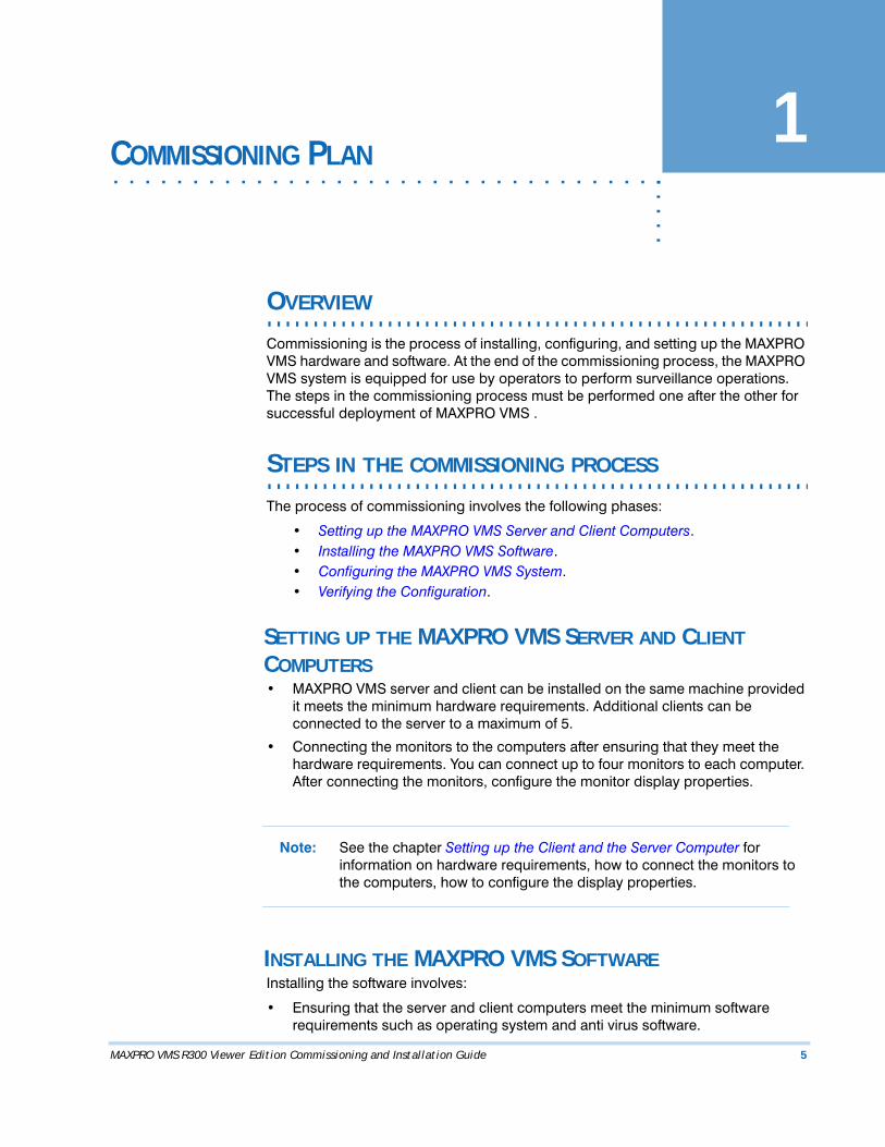
Commissioning is the process of installing, configuring, and setting up the MAXPRO VMS hardware and software. At the end of the commissioning process, the MAXPRO VMS system is equipped for use by operators to perform surveillance operations. The steps in the commissioning process must be performed one after the other for successful deployment of MAXPRO VMS .
. . . . . . . . . . . . . . . . . . . . . . . . . . . . . . . . . . . . . . . . . . . . . . . . . . . . . . . . . . .STEPS IN THE COMMISSIONING PROCESS
The process of commissioning involves the following phases:
• Setting up the MAXPRO VMS Server and Client Computers.• Installing the MAXPRO VMS Software.• Configuring the MAXPRO VMS System.• Verifying the Configuration.
SETTING UP THE MAXPRO VMS SERVER AND CLIENT COMPUTERS• MAXPRO VMS server and client can be installed on the same machine provided
it meets the minimum hardware requirements. Additional clients can be connected to the server to a maximum of 5.
• Connecting the monitors to the computers after ensuring that they meet the hardware requirements. You can connect up to four monitors to each computer. After connecting the monitors, configure the monitor display properties.
Note: See the chapter Setting up the Client and the Server Computer for information on hardware requirements, how to connect the monitors to the computers, how to configure the display properties.
INSTALLING THE MAXPRO VMS SOFTWAREInstalling the software involves:
• Ensuring that the server and client computers meet the minimum software requirements such as operating system and anti virus software.
C O M MI S S I O N I N G P L A N
Steps in the commissioning process
6 MAXPRO VMS R300 Viewer Edition Commissioning and Installation Guide
1
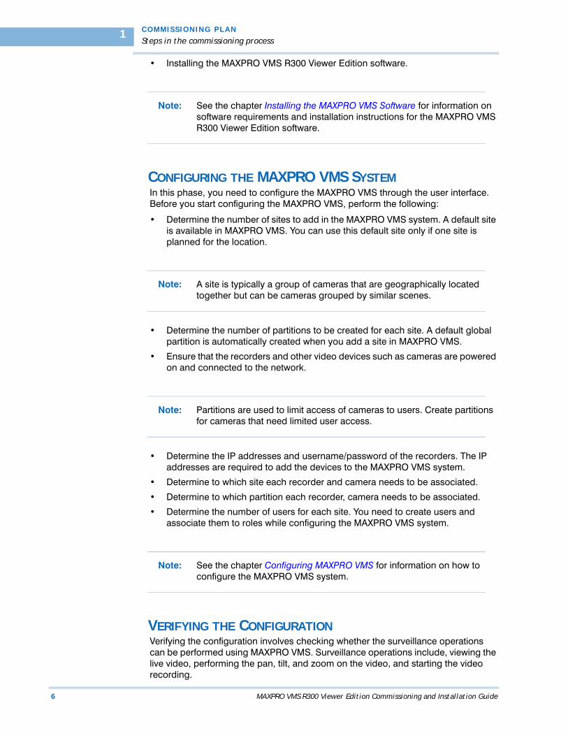
• Installing the MAXPRO VMS R300 Viewer Edition software.
Note: See the chapter Installing the MAXPRO VMS Software for information on software requirements and installation instructions for the MAXPRO VMS R300 Viewer Edition software.
CONFIGURING THE MAXPRO VMS SYSTEMIn this phase, you need to configure the MAXPRO VMS through the user interface. Before you start configuring the MAXPRO VMS, perform the following:
• Determine the number of sites to add in the MAXPRO VMS system. A default site is available in MAXPRO VMS. You can use this default site only if one site is planned for the location.
Note: A site is typically a group of cameras that are geographically located together but can be cameras grouped by similar scenes.
• Determine the number of partitions to be created for each site. A default global partition is automatically created when you add a site in MAXPRO VMS.
• Ensure that the recorders and other video devices such as cameras are powered on and connected to the network.
Note: Partitions are used to limit access of cameras to users. Create partitions for cameras that need limited user access.
• Determine the IP addresses and username/password of the recorders. The IP addresses are required to add the devices to the MAXPRO VMS system.
• Determine to which site each recorder and camera needs to be associated.
• Determine to which partition each recorder, camera needs to be associated.
• Determine the number of users for each site. You need to create users and associate them to roles while configuring the MAXPRO VMS system.
Note: See the chapter Configuring MAXPRO VMS for information on how to configure the MAXPRO VMS system.
VERIFYING THE CONFIGURATIONVerifying the configuration involves checking whether the surveillance operations can be performed using MAXPRO VMS. Surveillance operations include, viewing the live video, performing the pan, tilt, and zoom on the video, and starting the video recording.

. .
. .
.
C O M MI S S I O N I N G P L A N
Steps in the commissioning process
MAXPRO VMS R300 Viewer Edition Commissioning and Installation Guide 7
Note: See the chapter Verifying the Configuration of MAXPRO VMS R300 Viewer Edition for information on how to perform the verification.

C O M MI S S I O N I N G P L A N
Steps in the commissioning process
8 MAXPRO VMS R300 Viewer Edition Commissioning and Installation Guide
1
This page is intentionally left blank
MAXPRO VMS R300 Viewer Edition Commissioning and Installation Guide 9
2SETTING UP THE CLIENT AND THE SERVER
. . . . .. . . . . . . . . . . . . . . . . . . . . . . . . . . . . . . . . . .COMPUTER
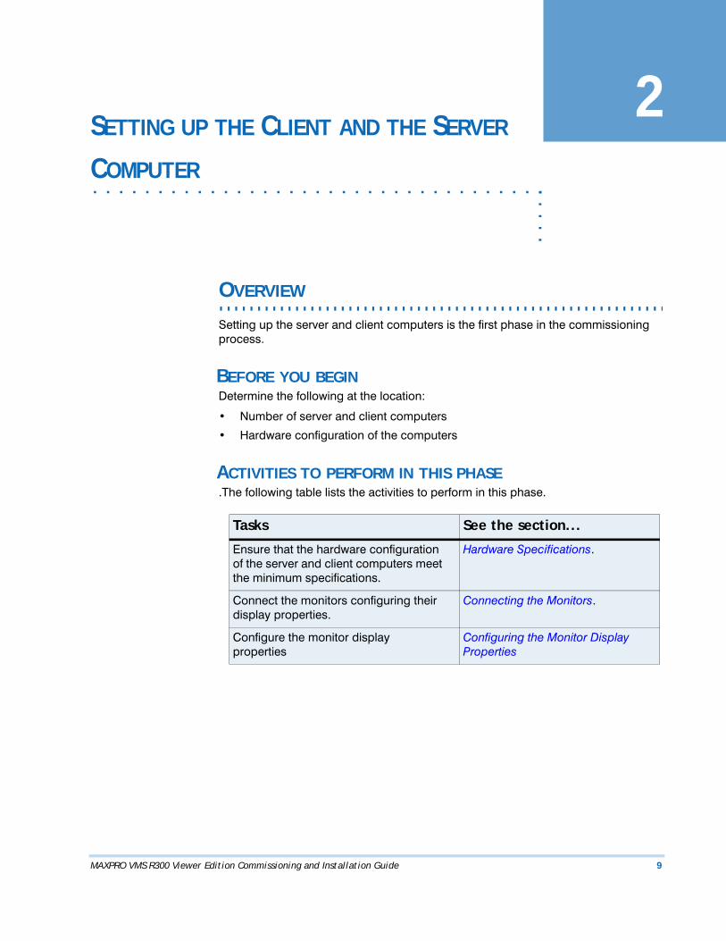
. . . . . . . . . . . . . . . . . . . . . . . . . . . . . . . . . . . . . . . . . . . . . . . . . . . . . . . . . . .OVERVIEW
Setting up the server and client computers is the first phase in the commissioning process.
BEFORE YOU BEGINDetermine the following at the location:
• Number of server and client computers
• Hardware configuration of the computers
ACTIVITIES TO PERFORM IN THIS PHASE.The following table lists the activities to perform in this phase.
Tasks See the section...
Ensure that the hardware configuration of the server and client computers meet the minimum specifications.
Hardware Specifications.
Connect the monitors configuring their display properties.
Connecting the Monitors.
Configure the monitor display properties
Configuring the Monitor Display Properties
S E T T I N G UP T H E C L I E N T AN D TH E S E R V ER C OM PUT ER
Hardware Specifications
10 MAXPRO VMS Express Edition Commissioning and Installation Guide
2
. . . . . . . . . . . . . . . . . . . . . . . . . . . . . . . . . . . . . . . . . . . . . . . . . . . . . . . . . . .HARDWARE SPECIFICATIONS
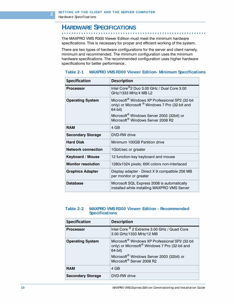
The MAXPRO VMS R300 Viewer Edition must meet the minimum hardware specifications. This is necessary for proper and efficient working of the system.
There are two types of hardware configurations for the server and client namely, minimum and recommended. The minimum configuration uses the minimum hardware specifications. The recommended configuration uses higher hardware specifications for better performance..
Table 2-1 MAXPRO VMS R300 Viewer Edition- Minimum Specifications
Specification Description
Processor Intel Core®2 Duo 3.00 GHz / Dual Core 3.00 GHz/1333 MHz/4 MB L2
Operating System Microsoft® Windows XP Professional SP2 (32-bit only) or Microsoft ® Windows 7 Pro (32-bit and 64-bit)
Microsoft® Windows Server 2003 (32bit) or Microsoft® Windows Server 2008 R2
RAM 4 GB
Secondary Storage DVD-RW drive
Hard Disk Minimum 100GB Partition drive
Network connection 1Gbit/sec or greater
Keyboard / Mouse 12 function-key keyboard and mouse
Monitor resolution 1280x1024 pixels; 65K colors non-interlaced
Graphics Adapter Display adapter - Direct X 9 compatible 256 MB per monitor or greater
Database Microsoft SQL Express 2008 is automatically installed while installing MAXPRO VMS Server
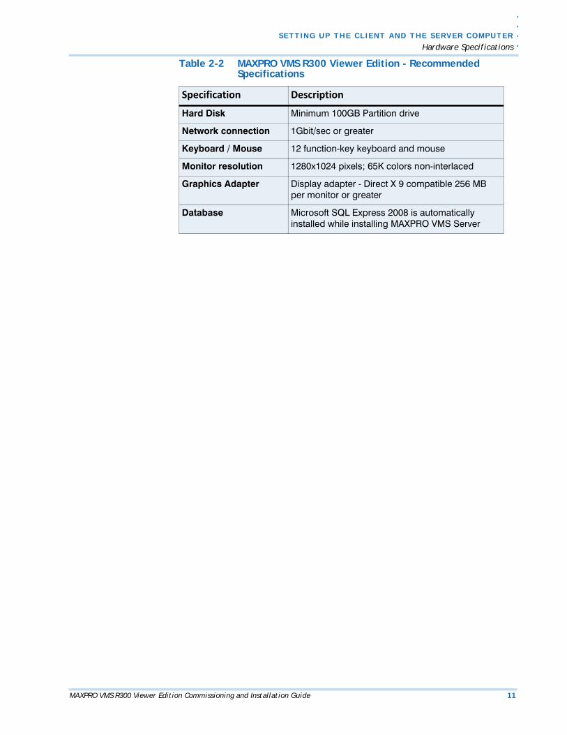
Table 2-2 MAXPRO VMS R300 Viewer Edition - Recommended Specifications
Specification Description
Processor Intel Core ® 2 Extreme 3.00 GHz / Quad Core 3.00 GHz/1333 MHz/12 MB
Operating System Microsoft® Windows XP Professional SP2 (32-bit only) or Microsoft® Windows 7 Pro (32-bit and 64-bit)
Microsoft® Windows Server 2003 (32bit) or Microsoft® Server 2008 R2
RAM 4 GB
Secondary Storage DVD-RW drive
. .
. .
.
S E TT I N G UP TH E C L I E NT AN D T H E S E RV E R C O MPU TE R
Hardware Specifications
MAXPRO VMS R300 Viewer Edition Commissioning and Installation Guide 11
Hard Disk Minimum 100GB Partition drive
Network connection 1Gbit/sec or greater
Keyboard / Mouse 12 function-key keyboard and mouse
Monitor resolution 1280x1024 pixels; 65K colors non-interlaced
Graphics Adapter Display adapter - Direct X 9 compatible 256 MB per monitor or greater
Database Microsoft SQL Express 2008 is automatically installed while installing MAXPRO VMS Server
Table 2-2 MAXPRO VMS R300 Viewer Edition - Recommended Specifications
Specification Description
S E T T I N G UP T H E C L I E N T AN D TH E S E R V ER C OM PUT ER
Connecting the Monitors
12 MAXPRO VMS Express Edition Commissioning and Installation Guide
2
. . . . . . . . . . . . . . . . . . . . . . . . . . . . . . . . . . . . . . . . . . . . . . . . . . . . . . . . . . .CONNECTING THE MONITORS
The number of monitors that you can connect to the computer depends on the type of graphics adapter. For example, up to four monitors can be connected to a dual head graphics adapter.
Caution: Before you begin, ensure that the computer and monitors are turned off.
CONFIGURING THE MONITOR DISPLAY PROPERTIESThe recommended display settings for the monitor are dialog box resolution of 1280 x 1024pixels and color quality of 65K colors non-interlaced. The display settings can be configured from the Windows control panel or from the Windows desktop through the context menu.
To configure the display settings from the context menu in the Windows desktop
1. Right-click the Windows desktop to display the context-menu.
2. Click Properties. The Display Properties dialog box appears.
3. Click the Settings tab.
4. Select the dialog box resolution and color quality.
5. Click Apply to save the settings.
6. Click OK to close the dialog box.
To configure the display settings from the Windows control panel
1. Go to Windows control panel.
Note: To open the control panel, choose Start > Settings > Control Panel.
2. Double-click the Display icon. The Display Properties dialog box appears.
3. Click the Settings tab.
4. Select the dialog box resolution and color quality.
5. Click Apply to save the settings.
6. Click OK to close the dialog box.
MAXPRO VMS R300 Viewer Edition Commissioning and Installation Guide 13
3. . . . .
. . . . . . . . . . . . . . . . . . . . . . . . . . . . . . . . . . .INSTALLING THE MAXPRO VMS SOFTWARE
. . . . . . . . . . . . . . . . . . . . . . . . . . . . . . . . . . . . . . . . . . . . . . . . . . . . . . . . . . .OVERVIEW
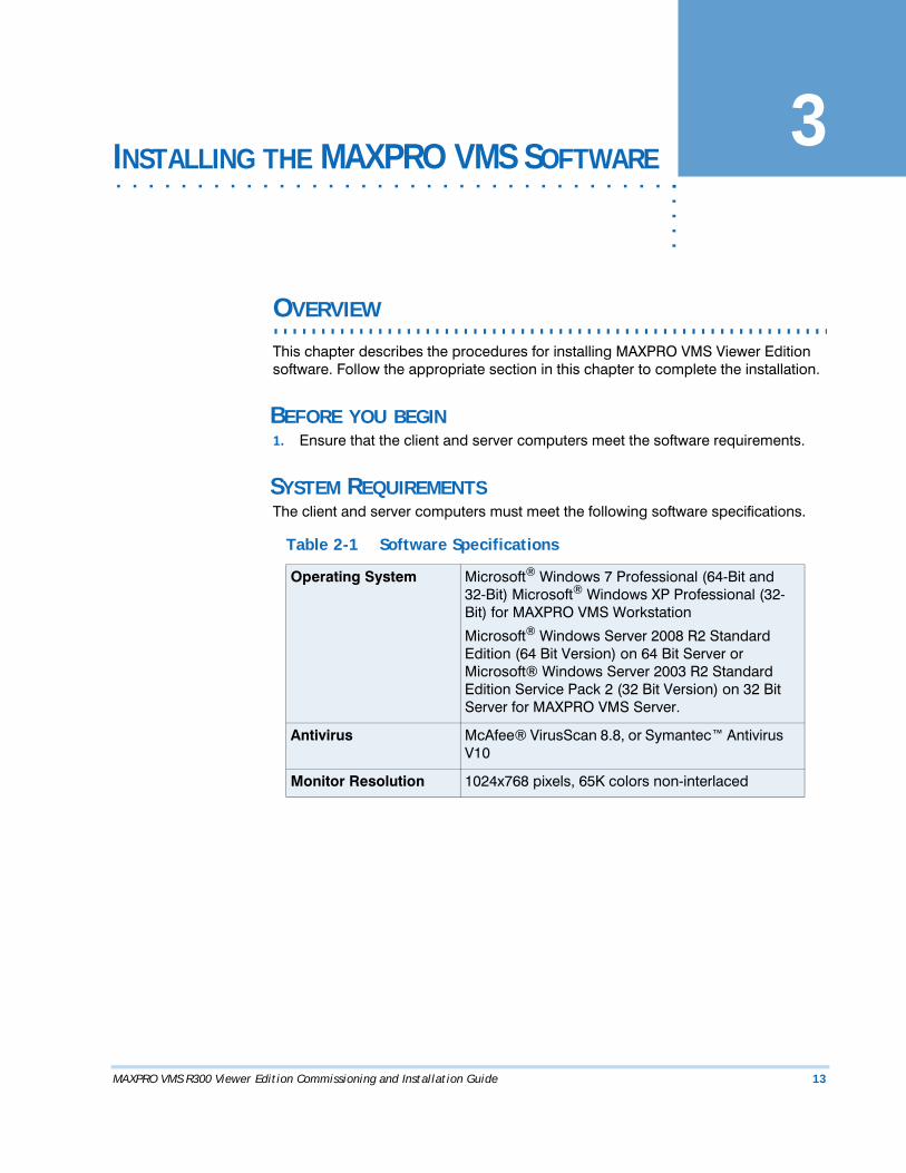
This chapter describes the procedures for installing MAXPRO VMS Viewer Edition software. Follow the appropriate section in this chapter to complete the installation.
BEFORE YOU BEGIN1. Ensure that the client and server computers meet the software requirements.
SYSTEM REQUIREMENTSThe client and server computers must meet the following software specifications.
Table 2-1 Software Specifications
Operating System Microsoft® Windows 7 Professional (64-Bit and 32-Bit) Microsoft® Windows XP Professional (32-Bit) for MAXPRO VMS Workstation
Microsoft® Windows Server 2008 R2 Standard Edition (64 Bit Version) on 64 Bit Server or Microsoft® Windows Server 2003 R2 Standard Edition Service Pack 2 (32 Bit Version) on 32 Bit Server for MAXPRO VMS Server.
Antivirus McAfee® VirusScan 8.8, or Symantec™ Antivirus V10
Monitor Resolution 1024x768 pixels, 65K colors non-interlaced

I N STALL I NG TH E MAXP RO VMS SOFTWAR E
Installing the MAXPRO VMS Software
14 MAXPRO VMS R300 Viewer Edition Commissioning and Installation Guide
3
. . . . . . . . . . . . . . . . . . . . . . . . . . . . . . . . . . . . . . . . . . . . . . . . . . . . . . . . . . .INSTALLING THE MAXPRO VMS SOFTWARE
To complete the MAXPRO VMS installation follow the procedures in these sections.
1. First, How to Install MAXPRO VMS Software
2. Choose the installation that best suits your requirements and follow the appropriate steps.
• Full Installation• Client Only Installation
. .
. .
.
I N S T A L L I N G T H E M AX P R O VM S S O F T W A R E
How to Install MAXPRO VMS Software
MAXPRO VMS R300 Viewer Edition Commissioning and Installation Guide 15
. . . . . . . . . . . . . . . . . . . . . . . . . . . . . . . . . . . . . . . . . . . . . . . . . . . . . . . . . . .HOW TO INSTALL MAXPRO VMS SOFTWARE
To install MAXPRO VMS software
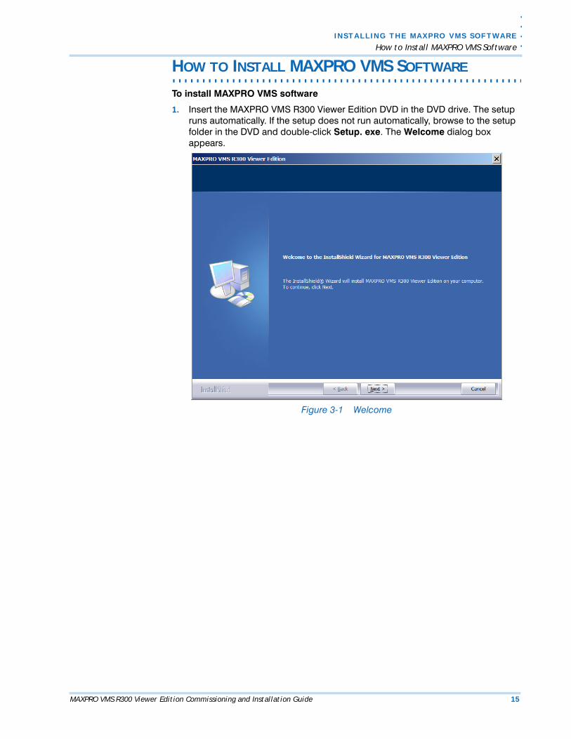
1. Insert the MAXPRO VMS R300 Viewer Edition DVD in the DVD drive. The setup runs automatically. If the setup does not run automatically, browse to the setup folder in the DVD and double-click Setup. exe. The Welcome dialog box appears.
Figure 3-1 Welcome
I N STALL I NG TH E MAXP RO VMS SOFTWAR E
How to Install MAXPRO VMS Software
16 MAXPRO VMS R300 Viewer Edition Commissioning and Installation Guide
3
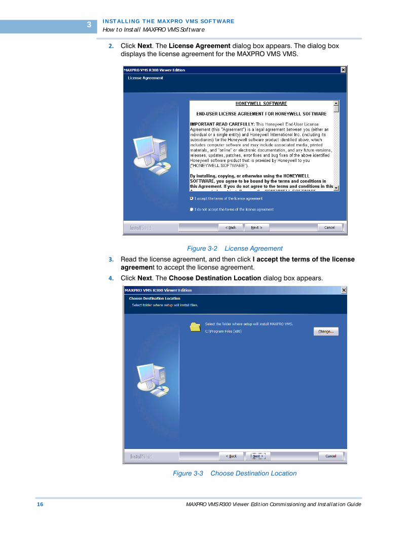
2. Click Next. The License Agreement dialog box appears. The dialog box displays the license agreement for the MAXPRO VMS VMS.
Figure 3-2 License Agreement
3. Read the license agreement, and then click I accept the terms of the license agreement to accept the license agreement.
4. Click Next. The Choose Destination Location dialog box appears.
Figure 3-3 Choose Destination Location
. .
. .
.
I N S T A L L I N G T H E M AX P R O VM S S O F T W A R E
How to Install MAXPRO VMS Software
MAXPRO VMS R300 Viewer Edition Commissioning and Installation Guide 17
Note: Click Change to change the default destination folder, and then select the folder where MAXPRO VMS must be installed.
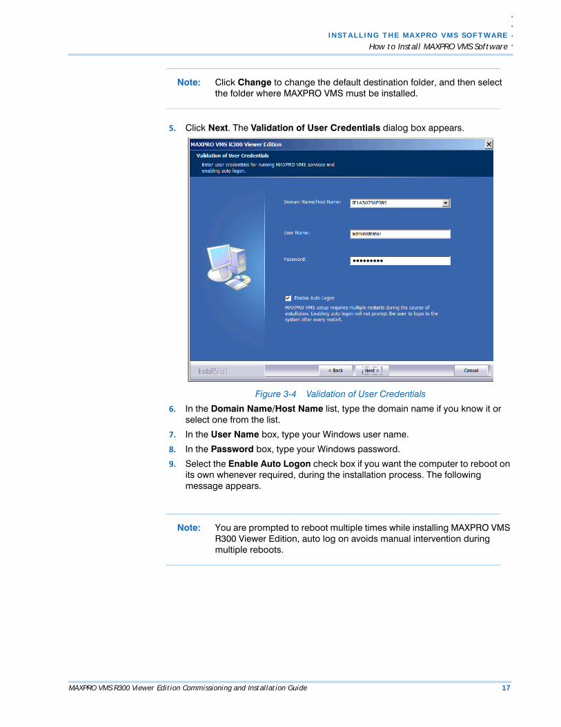
5. Click Next. The Validation of User Credentials dialog box appears.
Figure 3-4 Validation of User Credentials
6. In the Domain Name/Host Name list, type the domain name if you know it or select one from the list.
7. In the User Name box, type your Windows user name.
8. In the Password box, type your Windows password.
9. Select the Enable Auto Logon check box if you want the computer to reboot on its own whenever required, during the installation process. The following message appears.
Note: You are prompted to reboot multiple times while installing MAXPRO VMS R300 Viewer Edition, auto log on avoids manual intervention during multiple reboots.
I N STALL I NG TH E MAXP RO VMS SOFTWAR E
How to Install MAXPRO VMS Software
18 MAXPRO VMS R300 Viewer Edition Commissioning and Installation Guide
3
Figure 3-5 Enabling Auto Logon
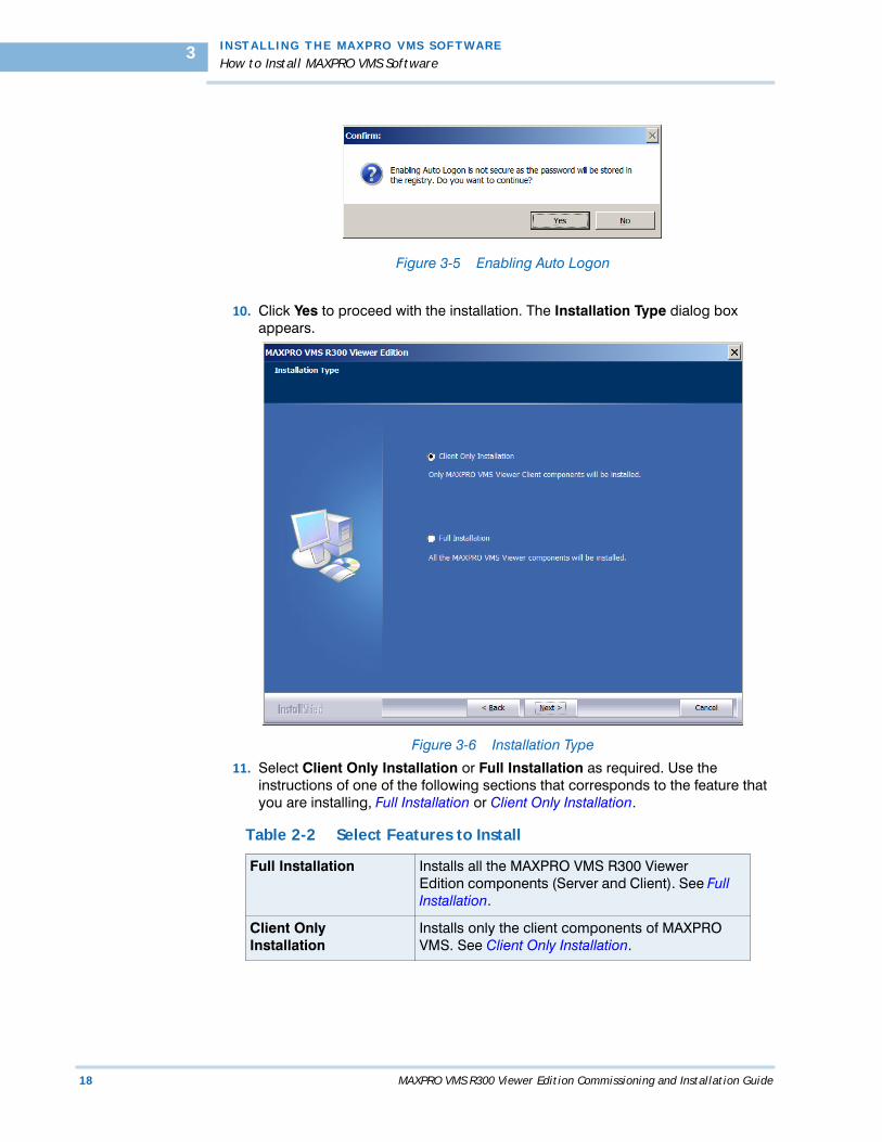
10. Click Yes to proceed with the installation. The Installation Type dialog box appears.
Figure 3-6 Installation Type
11. Select Client Only Installation or Full Installation as required. Use the instructions of one of the following sections that corresponds to the feature that you are installing, Full Installation or Client Only Installation.
Table 2-2 Select Features to Install
Full Installation Installs all the MAXPRO VMS R300 Viewer Edition components (Server and Client). See Full Installation.
Client Only Installation
Installs only the client components of MAXPRO VMS. See Client Only Installation.
. .
. .
.
I N S T A L L I N G T H E M AX P R O VM S S O F T W A R E
Full Installation
MAXPRO VMS R300 Viewer Edition Commissioning and Installation Guide 19
. . . . . . . . . . . . . . . . . . . . . . . . . . . . . . . . . . . . . . . . . . . . . . . . . . . . . . . . . . .FULL INSTALLATION
To perform full installation
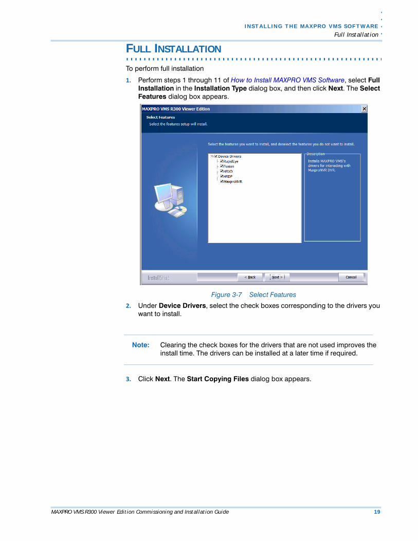
1. Perform steps 1 through 11 of How to Install MAXPRO VMS Software, select Full Installation in the Installation Type dialog box, and then click Next. The Select Features dialog box appears.
Figure 3-7 Select Features
2. Under Device Drivers, select the check boxes corresponding to the drivers you want to install.
Note: Clearing the check boxes for the drivers that are not used improves the install time. The drivers can be installed at a later time if required.
3. Click Next. The Start Copying Files dialog box appears.
I N STALL I NG TH E MAXP RO VMS SOFTWAR E
Full Installation
20 MAXPRO VMS R300 Viewer Edition Commissioning and Installation Guide
3
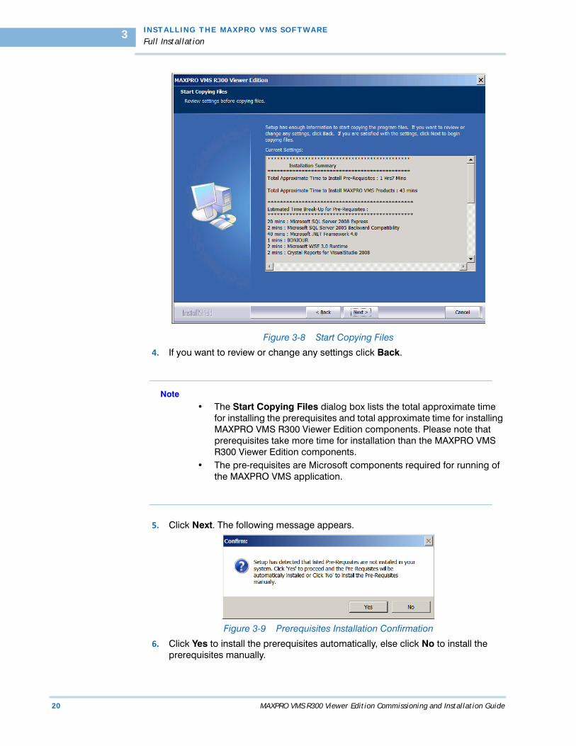
Figure 3-8 Start Copying Files
4. If you want to review or change any settings click Back.
Note
• The Start Copying Files dialog box lists the total approximate time for installing the prerequisites and total approximate time for installing MAXPRO VMS R300 Viewer Edition components. Please note that prerequisites take more time for installation than the MAXPRO VMS R300 Viewer Edition components.
• The pre-requisites are Microsoft components required for running of the MAXPRO VMS application.
5. Click Next. The following message appears.
Figure 3-9 Prerequisites Installation Confirmation
6. Click Yes to install the prerequisites automatically, else click No to install the prerequisites manually.
. .
. .
.
I N S T A L L I N G T H E M AX P R O VM S S O F T W A R E
Full Installation
MAXPRO VMS R300 Viewer Edition Commissioning and Installation Guide 21
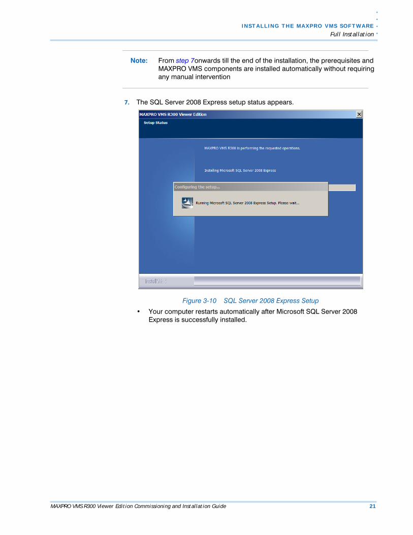
Note: From step 7onwards till the end of the installation, the prerequisites and MAXPRO VMS components are installed automatically without requiring any manual intervention
7. The SQL Server 2008 Express setup status appears.
Figure 3-10 SQL Server 2008 Express Setup
• Your computer restarts automatically after Microsoft SQL Server 2008 Express is successfully installed.
I N STALL I NG TH E MAXP RO VMS SOFTWAR E
Full Installation
22 MAXPRO VMS R300 Viewer Edition Commissioning and Installation Guide
3
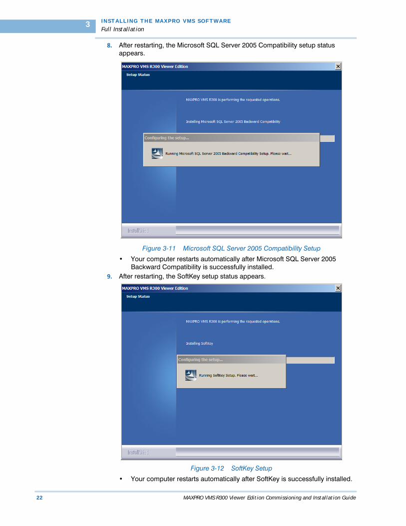
8. After restarting, the Microsoft SQL Server 2005 Compatibility setup status appears.
Figure 3-11 Microsoft SQL Server 2005 Compatibility Setup
• Your computer restarts automatically after Microsoft SQL Server 2005 Backward Compatibility is successfully installed.
9. After restarting, the SoftKey setup status appears.
Figure 3-12 SoftKey Setup
• Your computer restarts automatically after SoftKey is successfully installed.
. .
. .
.
I N S T A L L I N G T H E M AX P R O VM S S O F T W A R E
Full Installation
MAXPRO VMS R300 Viewer Edition Commissioning and Installation Guide 23
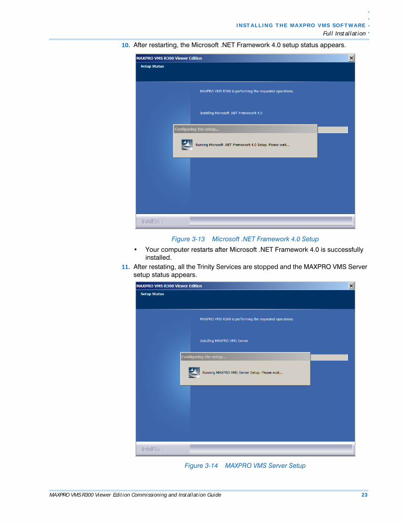
10. After restarting, the Microsoft .NET Framework 4.0 setup status appears.
Figure 3-13 Microsoft .NET Framework 4.0 Setup
• Your computer restarts after Microsoft .NET Framework 4.0 is successfully installed.
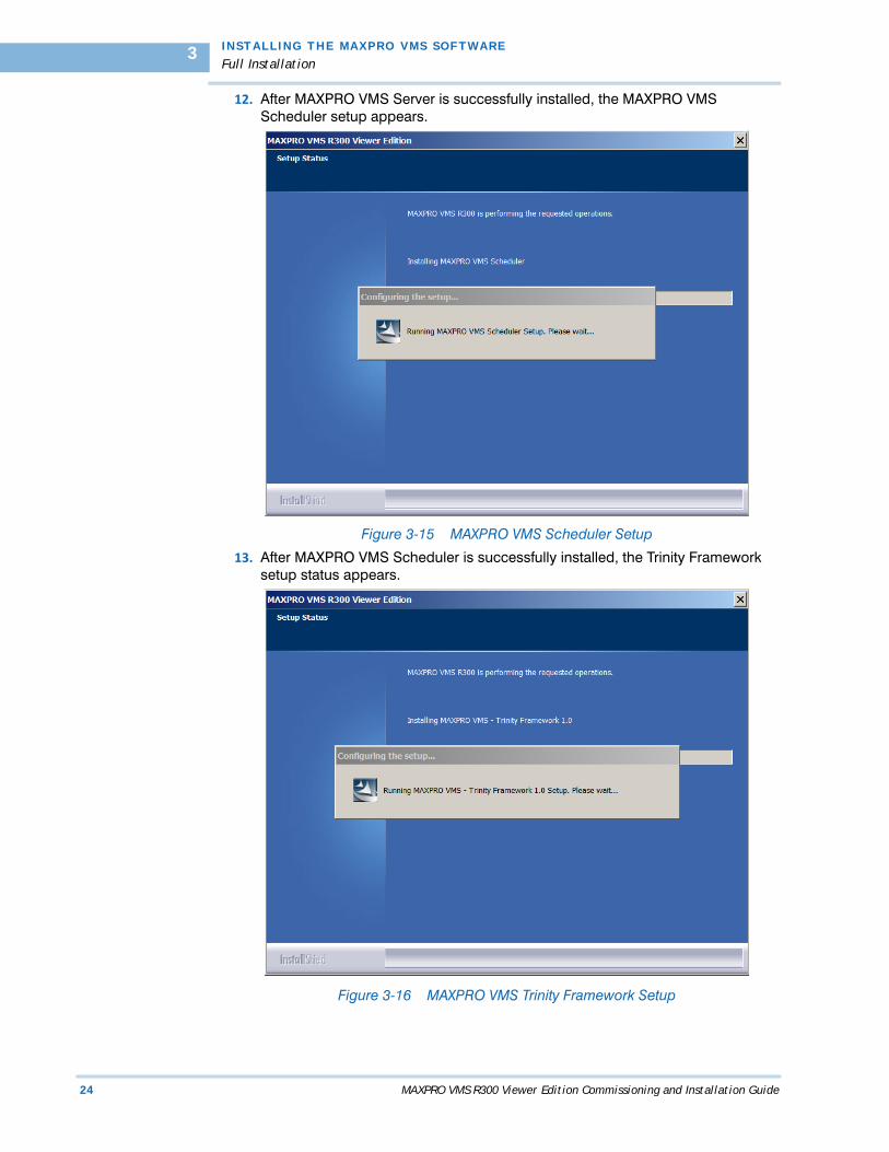
11. After restating, all the Trinity Services are stopped and the MAXPRO VMS Server setup status appears.
Figure 3-14 MAXPRO VMS Server Setup
I N STALL I NG TH E MAXP RO VMS SOFTWAR E
Full Installation
24 MAXPRO VMS R300 Viewer Edition Commissioning and Installation Guide
3
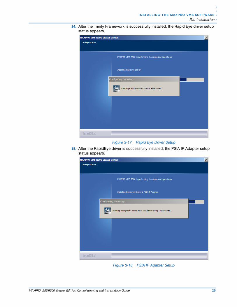
12. After MAXPRO VMS Server is successfully installed, the MAXPRO VMS Scheduler setup appears.
Figure 3-15 MAXPRO VMS Scheduler Setup
13. After MAXPRO VMS Scheduler is successfully installed, the Trinity Framework setup status appears.
Figure 3-16 MAXPRO VMS Trinity Framework Setup
. .
. .
.
I N S T A L L I N G T H E M AX P R O VM S S O F T W A R E
Full Installation
MAXPRO VMS R300 Viewer Edition Commissioning and Installation Guide 25
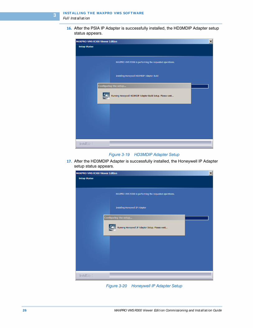
14. After the Trinity Framework is successfully installed, the Rapid Eye driver setup status appears.
Figure 3-17 Rapid Eye Driver Setup
15. After the RapidEye driver is successfully installed, the PSIA IP Adapter setup status appears.
Figure 3-18 PSIA IP Adapter Setup
I N STALL I NG TH E MAXP RO VMS SOFTWAR E
Full Installation
26 MAXPRO VMS R300 Viewer Edition Commissioning and Installation Guide
3
16. After the PSIA IP Adapter is successfully installed, the HD3MDIP Adapter setup status appears.
Figure 3-19 HD3MDIP Adapter Setup
17. After the HD3MDIP Adapter is successfully installed, the Honeywell IP Adapter setup status appears.
Figure 3-20 Honeywell IP Adapter Setup
. .
. .
.
I N S T A L L I N G T H E M AX P R O VM S S O F T W A R E
Full Installation
MAXPRO VMS R300 Viewer Edition Commissioning and Installation Guide 27
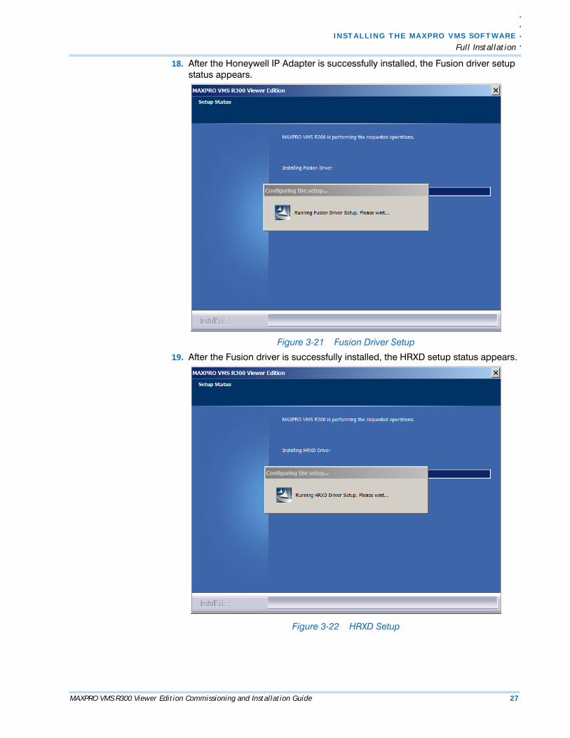
18. After the Honeywell IP Adapter is successfully installed, the Fusion driver setup status appears.
Figure 3-21 Fusion Driver Setup
19. After the Fusion driver is successfully installed, the HRXD setup status appears.
Figure 3-22 HRXD Setup
I N STALL I NG TH E MAXP RO VMS SOFTWAR E
Full Installation
28 MAXPRO VMS R300 Viewer Edition Commissioning and Installation Guide
3
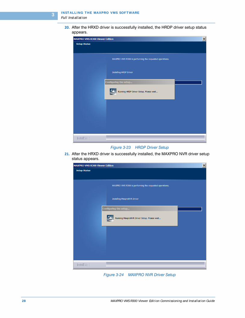
20. After the HRXD driver is successfully installed, the HRDP driver setup status appears.
Figure 3-23 HRDP Driver Setup
21. After the HRXD driver is successfully installed, the MAXPRO NVR driver setup status appears.
Figure 3-24 MAXPRO NVR Driver Setup

. .
. .
.
I N S T A L L I N G T H E M AX P R O VM S S O F T W A R E
Full Installation
MAXPRO VMS R300 Viewer Edition Commissioning and Installation Guide 29
22. After the MAXPRO NVR driver is successfully installed, the BONJOUR setup status appears.
Figure 3-25 BONJOUR Setup
23. After the BONJOUR is successfully installed, the HD3MDIP ActiveX setup status appears.
Figure 3-26 HD3MDIP ActiveX Setup
I N STALL I NG TH E MAXP RO VMS SOFTWAR E
Full Installation
30 MAXPRO VMS R300 Viewer Edition Commissioning and Installation Guide
3
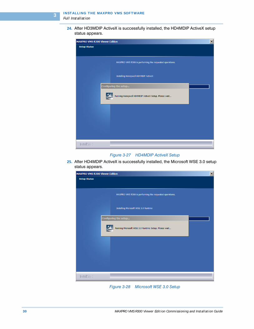
24. After HD3MDIP ActiveX is successfully installed, the HD4MDIP ActiveX setup status appears.
Figure 3-27 HD4MDIP ActiveX Setup
25. After HD4MDIP ActiveX is successfully installed, the Microsoft WSE 3.0 setup status appears.
Figure 3-28 Microsoft WSE 3.0 Setup
. .
. .
.
I N S T A L L I N G T H E M AX P R O VM S S O F T W A R E
Full Installation
MAXPRO VMS R300 Viewer Edition Commissioning and Installation Guide 31
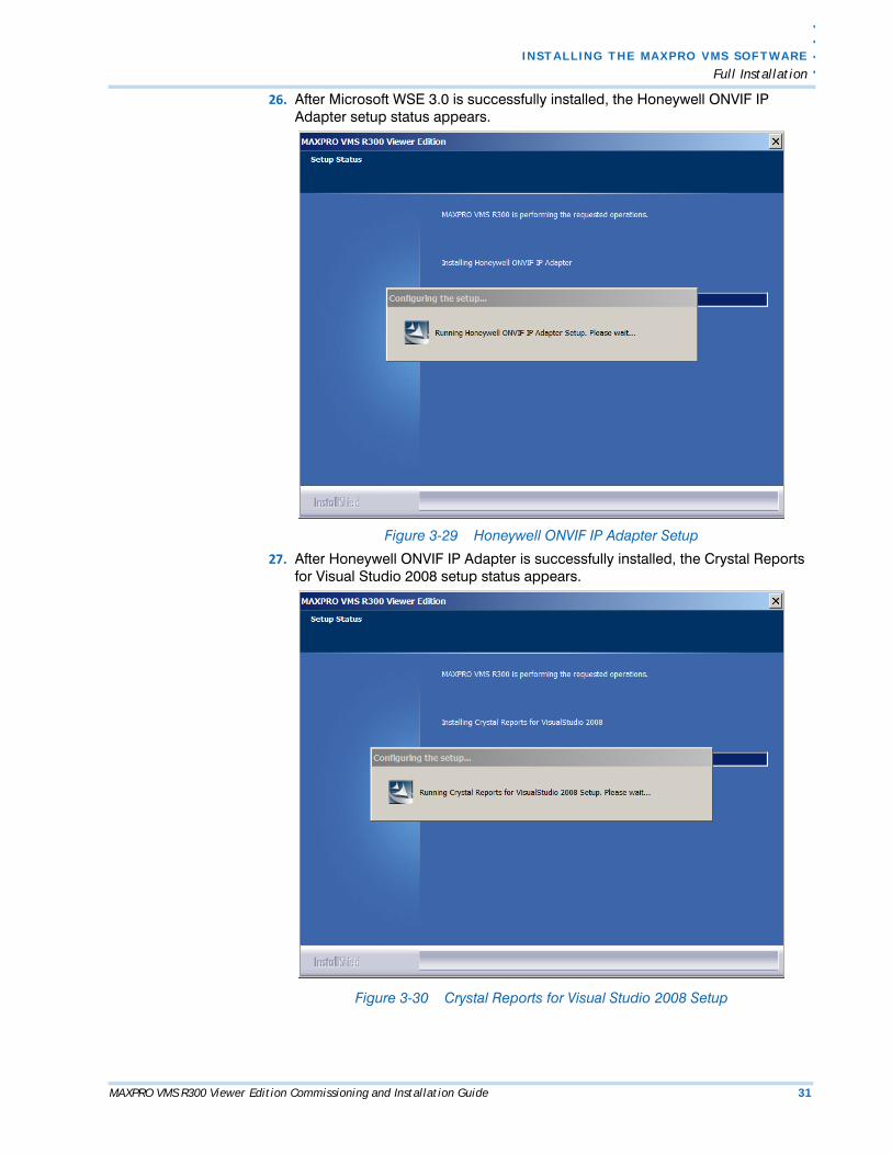
26. After Microsoft WSE 3.0 is successfully installed, the Honeywell ONVIF IP Adapter setup status appears.
Figure 3-29 Honeywell ONVIF IP Adapter Setup
27. After Honeywell ONVIF IP Adapter is successfully installed, the Crystal Reports for Visual Studio 2008 setup status appears.
Figure 3-30 Crystal Reports for Visual Studio 2008 Setup
I N STALL I NG TH E MAXP RO VMS SOFTWAR E
Full Installation
32 MAXPRO VMS R300 Viewer Edition Commissioning and Installation Guide
3
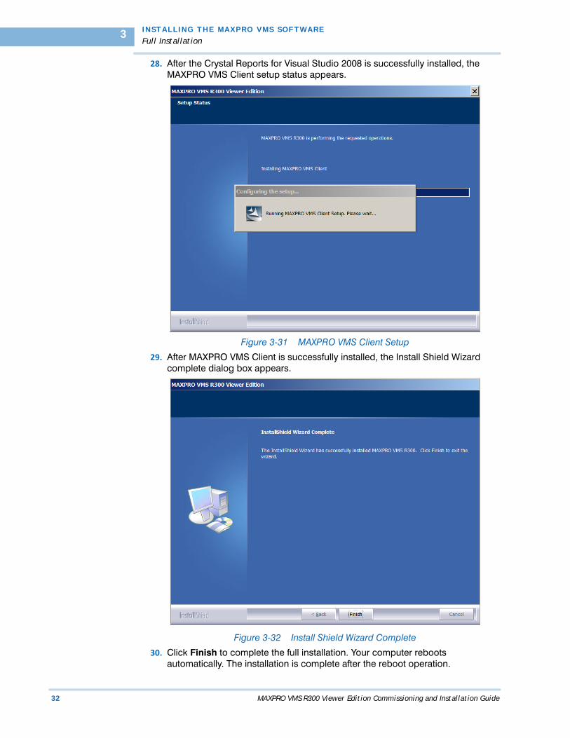
28. After the Crystal Reports for Visual Studio 2008 is successfully installed, the MAXPRO VMS Client setup status appears.
Figure 3-31 MAXPRO VMS Client Setup
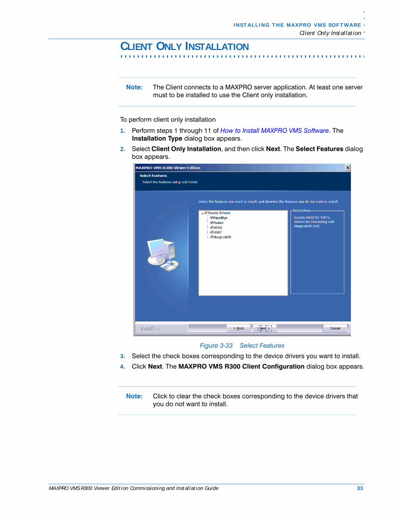
29. After MAXPRO VMS Client is successfully installed, the Install Shield Wizard complete dialog box appears.
Figure 3-32 Install Shield Wizard Complete
30. Click Finish to complete the full installation. Your computer reboots automatically. The installation is complete after the reboot operation.
. .
. .
.
I N S T A L L I N G T H E M AX P R O VM S S O F T W A R E
Client Only Installation
MAXPRO VMS R300 Viewer Edition Commissioning and Installation Guide 33
. . . . . . . . . . . . . . . . . . . . . . . . . . . . . . . . . . . . . . . . . . . . . . . . . . . . . . . . . . .CLIENT ONLY INSTALLATION
Note: The Client connects to a MAXPRO server application. At least one server must to be installed to use the Client only installation.
To perform client only installation
1. Perform steps 1 through 11 of How to Install MAXPRO VMS Software. The Installation Type dialog box appears.
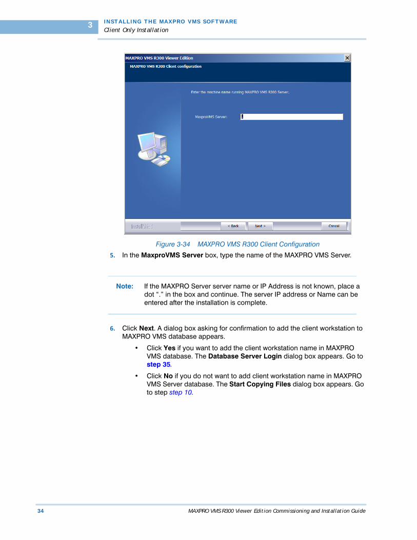
2. Select Client Only Installation, and then click Next. The Select Features dialog box appears.
Figure 3-33 Select Features
3. Select the check boxes corresponding to the device drivers you want to install.
4. Click Next. The MAXPRO VMS R300 Client Configuration dialog box appears.
Note: Click to clear the check boxes corresponding to the device drivers that you do not want to install.
I N STALL I NG TH E MAXP RO VMS SOFTWAR E
Client Only Installation
34 MAXPRO VMS R300 Viewer Edition Commissioning and Installation Guide
3
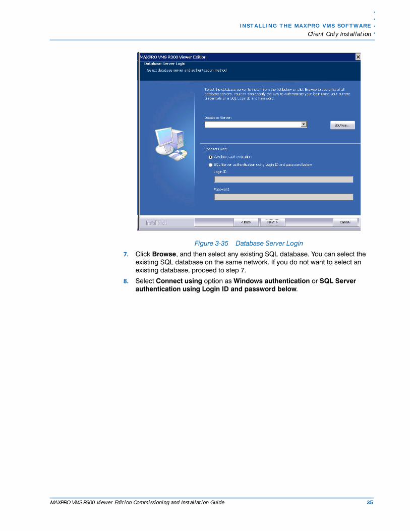
Figure 3-34 MAXPRO VMS R300 Client Configuration
5. In the MaxproVMS Server box, type the name of the MAXPRO VMS Server.
Note: If the MAXPRO Server server name or IP Address is not known, place a dot “.” in the box and continue. The server IP address or Name can be entered after the installation is complete.
6. Click Next. A dialog box asking for confirmation to add the client workstation to MAXPRO VMS database appears.
• Click Yes if you want to add the client workstation name in MAXPRO VMS database. The Database Server Login dialog box appears. Go to step 35.
• Click No if you do not want to add client workstation name in MAXPRO VMS Server database. The Start Copying Files dialog box appears. Go to step step 10.
. .
. .
.
I N S T A L L I N G T H E M AX P R O VM S S O F T W A R E
Client Only Installation
MAXPRO VMS R300 Viewer Edition Commissioning and Installation Guide 35
Figure 3-35 Database Server Login
7. Click Browse, and then select any existing SQL database. You can select the existing SQL database on the same network. If you do not want to select an existing database, proceed to step 7.
8. Select Connect using option as Windows authentication or SQL Server authentication using Login ID and password below.
I N STALL I NG TH E MAXP RO VMS SOFTWAR E
Client Only Installation
36 MAXPRO VMS R300 Viewer Edition Commissioning and Installation Guide
3
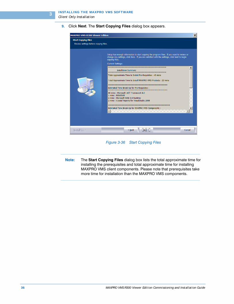
9. Click Next. The Start Copying Files dialog box appears.
Figure 3-36 Start Copying Files
Note: The Start Copying Files dialog box lists the total approximate time for installing the prerequisites and total approximate time for installing MAXPRO VMS client components. Please note that prerequisites take more time for installation than the MAXPRO VMS components.
. .
. .
.
I N S T A L L I N G T H E M AX P R O VM S S O F T W A R E
Client Only Installation
MAXPRO VMS R300 Viewer Edition Commissioning and Installation Guide 37
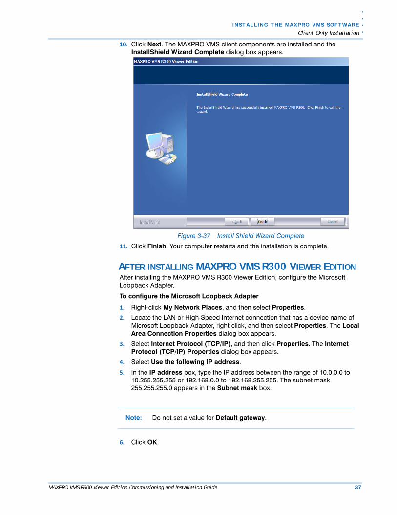
10. Click Next. The MAXPRO VMS client components are installed and the InstallShield Wizard Complete dialog box appears.
Figure 3-37 Install Shield Wizard Complete
11. Click Finish. Your computer restarts and the installation is complete.
AFTER INSTALLING MAXPRO VMS R300 VIEWER EDITIONAfter installing the MAXPRO VMS R300 Viewer Edition, configure the Microsoft Loopback Adapter.
To configure the Microsoft Loopback Adapter
1. Right-click My Network Places, and then select Properties.
2. Locate the LAN or High-Speed Internet connection that has a device name of Microsoft Loopback Adapter, right-click, and then select Properties. The Local Area Connection Properties dialog box appears.
3. Select Internet Protocol (TCP/IP), and then click Properties. The Internet Protocol (TCP/IP) Properties dialog box appears.
4. Select Use the following IP address.
5. In the IP address box, type the IP address between the range of 10.0.0.0 to 10.255.255.255 or 192.168.0.0 to 192.168.255.255. The subnet mask 255.255.255.0 appears in the Subnet mask box.
Note: Do not set a value for Default gateway.
6. Click OK.
I N STALL I NG TH E MAXP RO VMS SOFTWAR E
Removing MAXPRO VMS R300
38 MAXPRO VMS R300 Viewer Edition Commissioning and Installation Guide
3
. . . . . . . . . . . . . . . . . . . . . . . . . . . . . . . . . . . . . . . . . . . . . . . . . . . . . . . . . . .REMOVING MAXPRO VMS R300
You can remove the MAXPRO VMS completely or some of it’s components as per your requirement.
BEFORE YOU BEGIN1. Stop Trinity Services.
a.Choose Start>Run, and then type services.msc. The Services windowappears.
b.Right-click TrinityContoller, and then select Stop.
c.Right-click TrinityServer, and then select Stop.
To remove MAXPRO VMS completely
1. Insert the MAXPRO VMS R300 Viewer Edition setup DVD in the DVD drive, browse to the MAXPRO VMS R300 Viewer Edition setup folder, and then double-click Setup. exe or Go to the MAXPRO VMS R300 Viewer Edition setup folder in your computer, and then double-click Setup. exe. The Welcome dialog box appears.
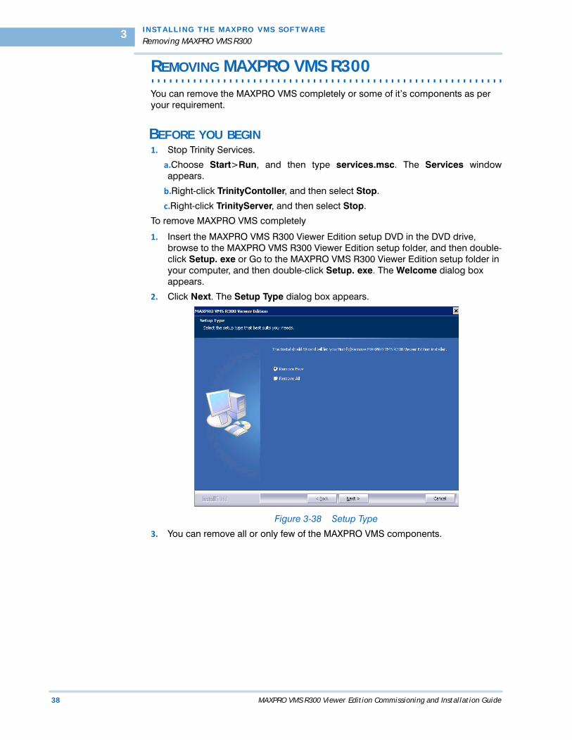
2. Click Next. The Setup Type dialog box appears.
Figure 3-38 Setup Type
3. You can remove all or only few of the MAXPRO VMS components.
. .
. .
.
I N S T A L L I N G T H E M AX P R O VM S S O F T W A R E
Removing MAXPRO VMS R300
MAXPRO VMS R300 Viewer Edition Commissioning and Installation Guide 39
To remove only few components
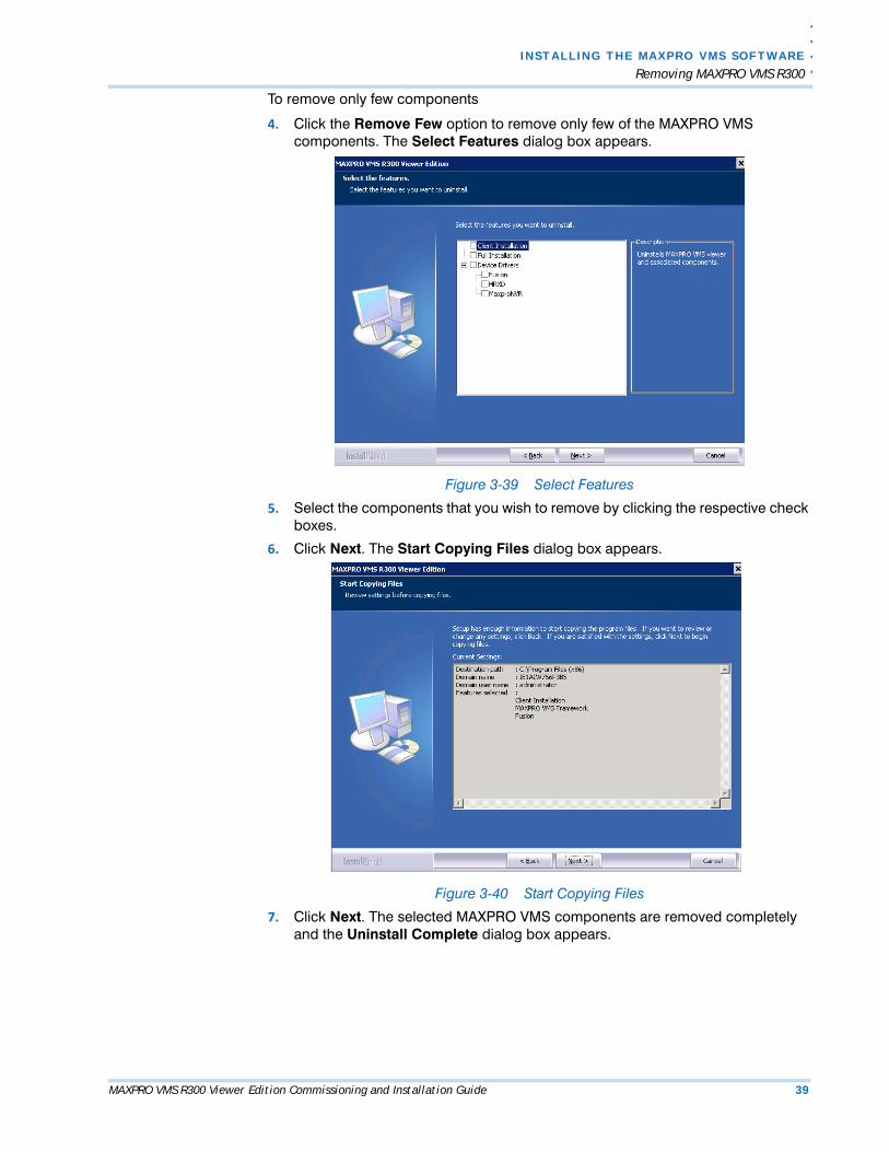
4. Click the Remove Few option to remove only few of the MAXPRO VMS components. The Select Features dialog box appears.
Figure 3-39 Select Features
5. Select the components that you wish to remove by clicking the respective check boxes.
6. Click Next. The Start Copying Files dialog box appears.
Figure 3-40 Start Copying Files
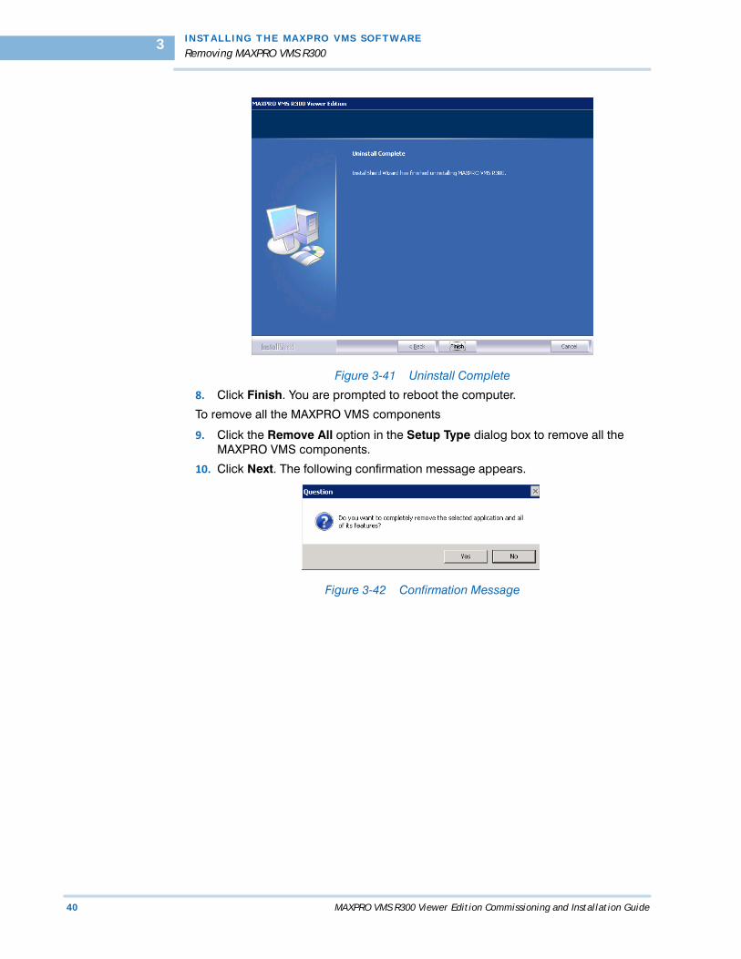
7. Click Next. The selected MAXPRO VMS components are removed completely and the Uninstall Complete dialog box appears.
I N STALL I NG TH E MAXP RO VMS SOFTWAR E
Removing MAXPRO VMS R300
40 MAXPRO VMS R300 Viewer Edition Commissioning and Installation Guide
3
Figure 3-41 Uninstall Complete
8. Click Finish. You are prompted to reboot the computer.
To remove all the MAXPRO VMS components
9. Click the Remove All option in the Setup Type dialog box to remove all the MAXPRO VMS components.
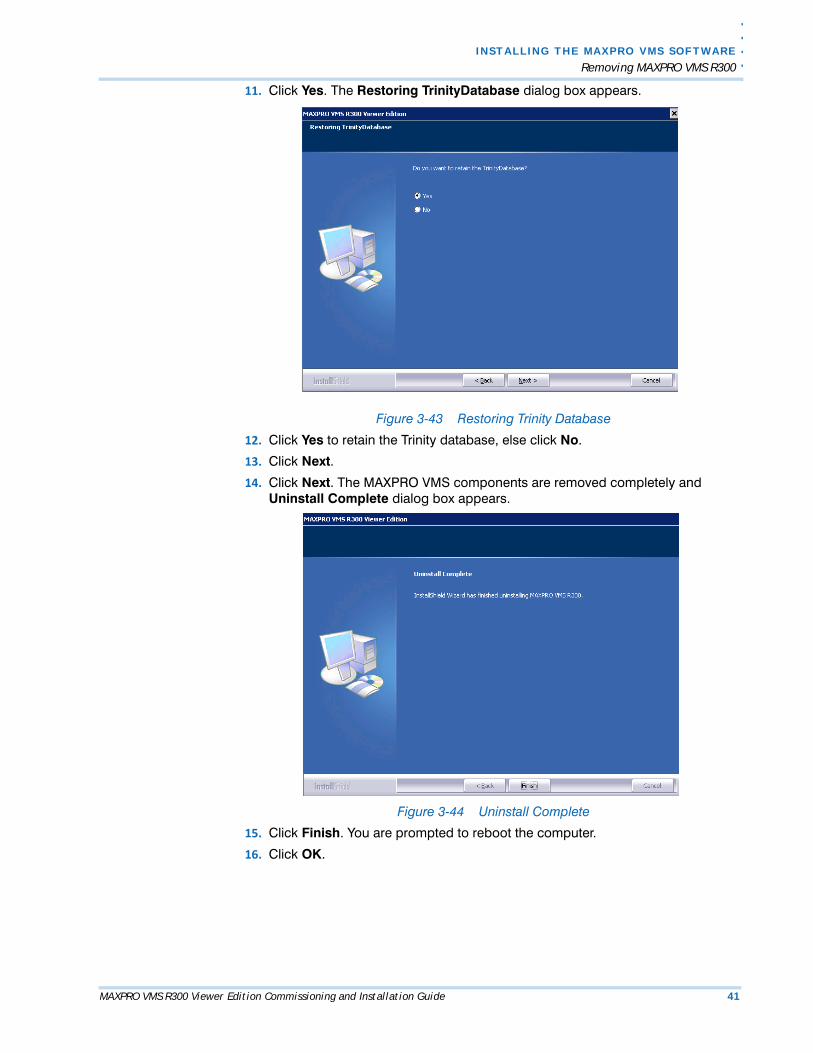
10. Click Next. The following confirmation message appears.
Figure 3-42 Confirmation Message
. .
. .
.
I N S T A L L I N G T H E M AX P R O VM S S O F T W A R E
Removing MAXPRO VMS R300
MAXPRO VMS R300 Viewer Edition Commissioning and Installation Guide 41
11. Click Yes. The Restoring TrinityDatabase dialog box appears.
Figure 3-43 Restoring Trinity Database
12. Click Yes to retain the Trinity database, else click No.
13. Click Next.
14. Click Next. The MAXPRO VMS components are removed completely and Uninstall Complete dialog box appears.
Figure 3-44 Uninstall Complete
15. Click Finish. You are prompted to reboot the computer.
16. Click OK.
I N STALL I NG TH E MAXP RO VMS SOFTWAR E
Removing MAXPRO VMS R300
42 MAXPRO VMS R300 Viewer Edition Commissioning and Installation Guide
3
Note: You can remove the required component using the Add or Remove Programs in Windows. However, Honeywell recommends to follow the above mentioned steps to remove the MAXPRO VMS components.
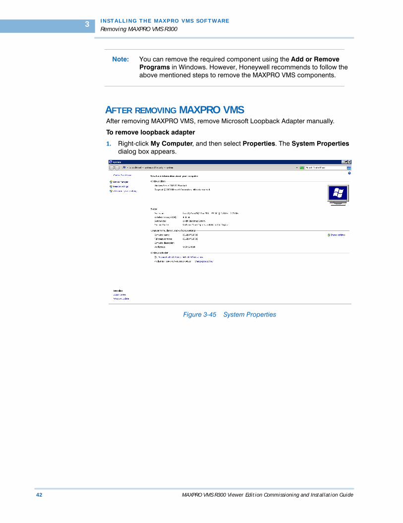
AFTER REMOVING MAXPRO VMS After removing MAXPRO VMS, remove Microsoft Loopback Adapter manually.
To remove loopback adapter
1. Right-click My Computer, and then select Properties. The System Properties dialog box appears.
Figure 3-45 System Properties
. .
. .
.
I N S T A L L I N G T H E M AX P R O VM S S O F T W A R E
Removing MAXPRO VMS R300
MAXPRO VMS R300 Viewer Edition Commissioning and Installation Guide 43
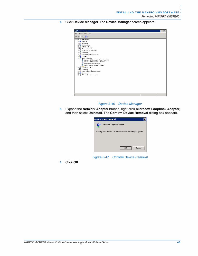
2. Click Device Manager. The Device Manager screen appears.
Figure 3-46 Device Manager
3. Expand the Network Adapter branch, right-click Microsoft Loopback Adapter, and then select Uninstall. The Confirm Device Removal dialog box appears.
Figure 3-47 Confirm Device Removal
4. Click OK.
I N STALL I NG TH E MAXP RO VMS SOFTWAR E
Upgrading to MAXPRO VMS R300
44 MAXPRO VMS R300 Viewer Edition Commissioning and Installation Guide
3
. . . . . . . . . . . . . . . . . . . . . . . . . . . . . . . . . . . . . . . . . . . . . . . . . . . . . . . . . . .UPGRADING TO MAXPRO VMS R300
OVERVIEWThis chapter describes the procedure for upgrading MAXPRO VMS software from VMS R300 Viewer Edition to MAXPRO VMS R300. Follow the appropriate section in this chapter to complete your MAXPRO VMS software migration.
BEFORE YOU BEGIN1. Ensure that the client and server computers meet the software requirements.
. .
. .
.
I N S T A L L I N G T H E M AX P R O VM S S O F T W A R E
Upgrading MAXPRO VMS R300 Viewer Edition
MAXPRO VMS R300 Viewer Edition Commissioning and Installation Guide 45
. . . . . . . . . . . . . . . . . . . . . . . . . . . . . . . . . . . . . . . . . . . . . . . . . . . . . . . . . . .UPGRADING MAXPRO VMS R300 VIEWER EDITION
See the procedures in the following sections to upgrade to MAXPRO VMS R300 Enterprise Edition.
BEFORE YOU BEGIN1. Stop Trinity Services.
a.Choose Start>Run, and then type services.msc. The Services window appears.
b.Right-click TrinityContoller, and then select Stop.
c.Right-click TrinityServer, and then select Stop.
To upgrade to MAXPRO VMS R300
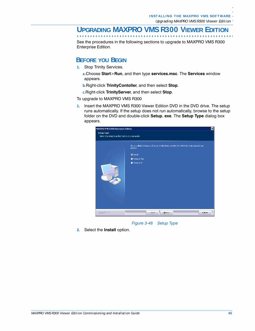
1. Insert the MAXPRO VMS R300 Viewer Edition DVD in the DVD drive. The setup runs automatically. If the setup does not run automatically, browse to the setup folder on the DVD and double-click Setup. exe. The Setup Type dialog box appears.
Figure 3-48 Setup Type
2. Select the Install option.
I N STALL I NG TH E MAXP RO VMS SOFTWAR E
Upgrading MAXPRO VMS R300 Viewer Edition
46 MAXPRO VMS R300 Viewer Edition Commissioning and Installation Guide
3
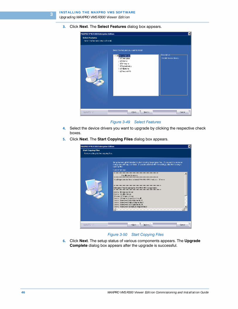
3. Click Next. The Select Features dialog box appears.
Figure 3-49 Select Features
4. Select the device drivers you want to upgrade by clicking the respective check boxes.
5. Click Next. The Start Copying Files dialog box appears.
Figure 3-50 Start Copying Files
6. Click Next. The setup status of various components appears. The Upgrade Complete dialog box appears after the upgrade is successful.
MAXPRO VMS R300 Viewer Edition Commissioning and Installation Guide 47
4. . . . .
. . . . . . . . . . . . . . . . . . . . . . . . . . . . . . . . . . .CONFIGURING MAXPRO VMS
. . . . . . . . . . . . . . . . . . . . . . . . . . . . . . . . . . . . . . . . . . . . . . . . . . . . . . . . . . .OVERVIEW
Configuring MAXPRO VMS involves setting up the application to perform surveillance operations. This is the most important phase for commissioning MAXPRO VMS as it involves organizing devices, users, and roles associated to them.
ACTIVITIES TO PERFORM IN THIS PHASE In this phase, using the MAXPRO VMS user interface perform the tasks listed in the following table.
BEFORE YOU BEGIN• Ensure that you have completed MAXPRO VMS server and client hardware
setup and software installation.• Configure the firewall settings as mentioned in the Firewall Settings section.
Task 0n...
Adding Profiles page 53
Adding Sites page 54
Adding Client Workstations page 55
Adding Users page 55
Adding Partitions page 56
Adding and configuring Recorders page 57
Adding and configuring Video Inputs page 58
Adding and configuring Relays page 59
Creating Sequences page 61
Adding Desktop Shortcuts page 74
C O N F I G U R I N G M A X P R O V M S
Firewall Settings
48 MAXPRO VMS R300 Viewer Edition Commissioning and Installation Guide
4
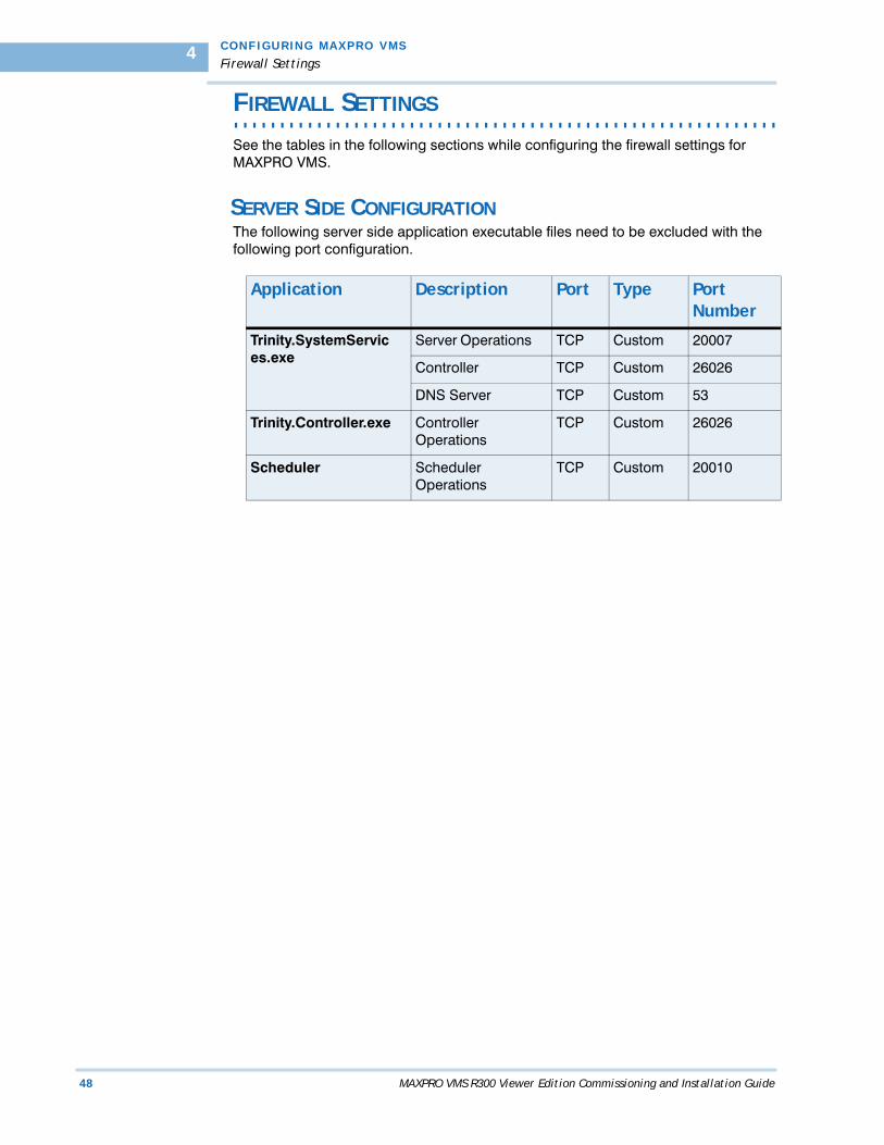
. . . . . . . . . . . . . . . . . . . . . . . . . . . . . . . . . . . . . . . . . . . . . . . . . . . . . . . . . . .FIREWALL SETTINGS
See the tables in the following sections while configuring the firewall settings for MAXPRO VMS.
SERVER SIDE CONFIGURATION The following server side application executable files need to be excluded with the following port configuration.
Application Description Port Type Port Number
Trinity.SystemServices.exe
Server Operations TCP Custom 20007
Controller TCP Custom 26026
DNS Server TCP Custom 53
Trinity.Controller.exe Controller Operations
TCP Custom 26026
Scheduler Scheduler Operations
TCP Custom 20010
. .
. .
.
C O N F I G U R I N G M A X P R O V M S
Firewall Settings
MAXPRO VMS R300 Viewer Edition Commissioning and Installation Guide 49
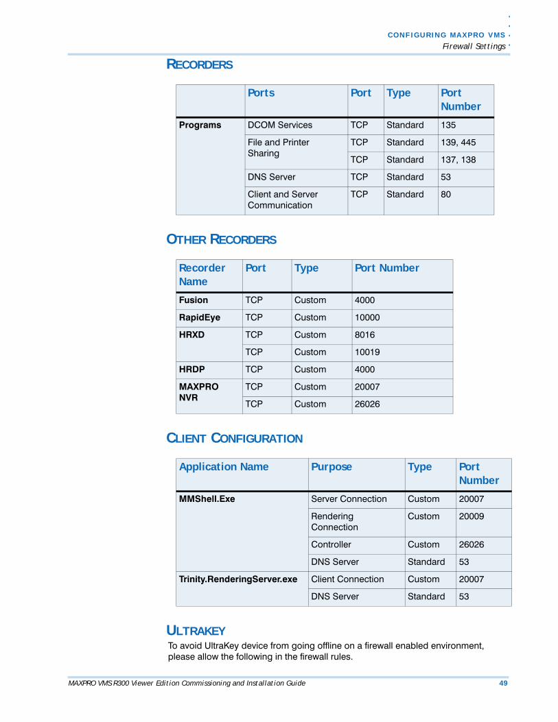
RECORDERS
OTHER RECORDERS
CLIENT CONFIGURATION
ULTRAKEYTo avoid UltraKey device from going offline on a firewall enabled environment, please allow the following in the firewall rules.
Ports Port Type Port Number
Programs DCOM Services TCP Standard 135
File and Printer Sharing
TCP Standard 139, 445
TCP Standard 137, 138
DNS Server TCP Standard 53
Client and Server Communication
TCP Standard 80
Recorder Name
Port Type Port Number
Fusion TCP Custom 4000
RapidEye TCP Custom 10000
HRXD TCP Custom 8016
TCP Custom 10019
HRDP TCP Custom 4000
MAXPRO NVR
TCP Custom 20007
TCP Custom 26026
Application Name Purpose Type Port Number
MMShell.Exe Server Connection Custom 20007
Rendering Connection
Custom 20009
Controller Custom 26026
DNS Server Standard 53
Trinity.RenderingServer.exe Client Connection Custom 20007
DNS Server Standard 53

C O N F I G U R I N G M A X P R O V M S
Firewall Settings
50 MAXPRO VMS R300 Viewer Edition Commissioning and Installation Guide
4
• ICMP 'echo-request' (type 8) packets out.
• ICMP 'echo-reply' (type 0) packets in.
. .
. .
.
C O N F I G U R I N G M A X P R O V M S
Configuring MAXPRO VMS R300 Viewer Edition
MAXPRO VMS R300 Viewer Edition Commissioning and Installation Guide 51
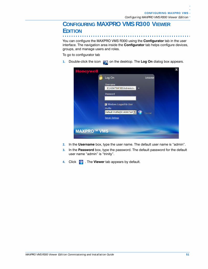
CONFIGURING MAXPRO VMS R300 VIEWER
. . . . . . . . . . . . . . . . . . . . . . . . . . . . . . . . . . . . . . . . . . . . . . . . . . . . . . . . . . .EDITION
You can configure the MAXPRO VMS R300 using the Configurator tab in the user interface. The navigation area inside the Configurator tab helps configure devices, groups, and manage users and roles.
To go to configurator tab
1. Double-click the icon on the desktop. The Log On dialog box appears.
2. In the Username box, type the user name. The default user name is “admin”.
3. In the Password box, type the password. The default password for the default user name “admin” is “trinity”.
4. Click . The Viewer tab appears by default.
C O N F I G U R I N G M A X P R O V M S
Configuring MAXPRO VMS R300 Viewer Edition
52 MAXPRO VMS R300 Viewer Edition Commissioning and Installation Guide
4
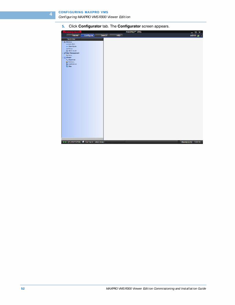
5. Click Configurator tab. The Configurator screen appears.
. .
. .
.
C O N F I G U R I N G M A X P R O V M S
Adding Profile
MAXPRO VMS R300 Viewer Edition Commissioning and Installation Guide 53
. . . . . . . . . . . . . . . . . . . . . . . . . . . . . . . . . . . . . . . . . . . . . . . . . . . . . . . . . . .ADDING PROFILE
Server addresses are saved in profiles. You need a profile to log on to MAXPRO VMS You can add, modify, and delete a profile through the log on dialog box.
To add, modify or delete a profile
1. Double-click the icon on the desktop. The Log On dialog box appears
2. Click Server Settings. The Server Settings dialog box appears.
3. You can add, delete or modify a profile using the Server Settings dialog box.
Note: For more information on how to add profiles, refer to the MAXPRO VMS R300 Viewer Edition Help.
C O N F I G U R I N G M A X P R O V M S
Adding Sites
54 MAXPRO VMS R300 Viewer Edition Commissioning and Installation Guide
4
. . . . . . . . . . . . . . . . . . . . . . . . . . . . . . . . . . . . . . . . . . . . . . . . . . . . . . . . . . .ADDING SITES
A site is added to associate cameras, recorders, switchers, and monitor. By default, one site is available in MAXPRO VMS R300 Viewer Edition. If only one site is needed at the location, you can use the default site. Any number of sites can be added as per your requirements.
To add a site
1. Go to Configurator tab.
2. Expand the Groups branch in the navigation area, and then click Sites.
Note: For more information on how to add sites, refer to the MAXPRO VMS R300 Viewer Edition Help.

. .
. .
.
C O N F I G U R I N G M A X P R O V M S
Adding Users
MAXPRO VMS R300 Viewer Edition Commissioning and Installation Guide 55
. . . . . . . . . . . . . . . . . . . . . . . . . . . . . . . . . . . . . . . . . . . . . . . . . . . . . . . . . . .ADDING USERS
By default, user named “admin” is created with administrator role. This user is privileged to add new users, assign roles to them, and associate them to partitions, event groups, workstations, and joystick controllers. You can restrict a user from viewing and modifying the settings of video devices. You can also dissociate privileges to a user.
To add a user
1. Go to Configurator tab.
2. Expand the User Management branch in the navigation area, and then click Users.
Note: For more information on how to add users, refer to the MAXPRO VMS R300 Viewer Edition Help.
C O N F I G U R I N G M A X P R O V M S
Adding Partitions
56 MAXPRO VMS R300 Viewer Edition Commissioning and Installation Guide
4
. . . . . . . . . . . . . . . . . . . . . . . . . . . . . . . . . . . . . . . . . . . . . . . . . . . . . . . . . . .ADDING PARTITIONS
Devices and users are associated to partitions. Only users associated to a partition can use the devices in that partition. By default, a partition is created and all the devices and users are associated with it. You can create any number of partitions based on the requirements.
You can associate devices and users to a partition while you are adding them. You can also dissociate the partition from devices and users.
To add a partition
1. Go to Configurator tab.
2. Expand the Groups branch in the navigation area, and then click Partitions.
Note: For more information on how to add partitions, refer to the MAXPRO VMS R300 Viewer Edition Help.

. .
. .
.
C O N F I G U R I N G M A X P R O V M S
Adding and Configuring the Recorders
MAXPRO VMS R300 Viewer Edition Commissioning and Installation Guide 57
. . . . . . . . . . . . . . . . . . . . . . . . . . . . . . . . . . . . . . . . . . . . . . . . . . . . . . . . . . .ADDING AND CONFIGURING THE RECORDERS
You can add a recorder and modify the settings as per your requirements. You can also select the site for the recorder, and associate partitions and events.
To add and configure a recorder
1. Go to Configurator tab.
2. Expand the Devices branch in the navigation area, and then click Recorders.
Note: For more information on how to add and configure recorders, refer to the MAXPRO VMS R300 Viewer Edition Help.

C O N F I G U R I N G M A X P R O V M S
Adding and Configuring Video Inputs
58 MAXPRO VMS R300 Viewer Edition Commissioning and Installation Guide
4
. . . . . . . . . . . . . . . . . . . . . . . . . . . . . . . . . . . . . . . . . . . . . . . . . . . . . . . . . . .ADDING AND CONFIGURING VIDEO INPUTS
You can add and configure both digital and analog cameras in MAXPRO VMS. Recorders are associated with the cameras. Cameras can be associated to partitions for logical grouping.
To add and configure cameras
1. Go to Configurator tab.
2. Expand the Devices branch in the navigation area, and then click Video Inputs.
Note: For more information on how to add and configure cameras, refer to the MAXPRO VMS R300 Viewer Edition Help.

. .
. .
.
C O N F I G U R I N G M A X P R O V M S
Adding and Configuring Relays
MAXPRO VMS R300 Viewer Edition Commissioning and Installation Guide 59
. . . . . . . . . . . . . . . . . . . . . . . . . . . . . . . . . . . . . . . . . . . . . . . . . . . . . . . . . . .ADDING AND CONFIGURING RELAYS
You can add or delete a relay in MAXPRO VMS R300 Viewer Edition. Relays can be connected to devices like recorders, cameras. Relays send signals that perform various actions. For example, you can set a relay to open the door automatically when a motion is detected in a particular region.
To add and configure relays
1. Go to Configurator tab.
2. Expand the Devices branch in the navigation area, and then click Relays.
Note: For more information on how to add and configure relays, refer to the MAXPRO VMS R300 Viewer Edition Help.

C O N F I G U R I N G M A X P R O V M S
Adding and connecting Alarm Inputs
60 MAXPRO VMS R300 Viewer Edition Commissioning and Installation Guide
4
. . . . . . . . . . . . . . . . . . . . . . . . . . . . . . . . . . . . . . . . . . . . . . . . . . . . . . . . . . .ADDING AND CONNECTING ALARM INPUTS
You can add alarm inputs to raise alarms through an external device in MAXPRO VMS.
To add alarm inputs
1. Go to Configurator tab.
2. Expand the Devices branch in the navigation area, and then click Alarm Inputs.
Note: For more information on how to add alarm inputs, refer to the MAXPRO VMS R300 Viewer Edition Help.
. .
. .
.
C O N F I G U R I N G M A X P R O V M S
Creating Sequences
MAXPRO VMS R300 Viewer Edition Commissioning and Installation Guide 61
. . . . . . . . . . . . . . . . . . . . . . . . . . . . . . . . . . . . . . . . . . . . . . . . . . . . . . . . . . .CREATING SEQUENCES
After you have configured all the devices and users, you have the option of creating sequences. Sequences display live video from the cameras or presets for a specified time interval. You can select the cameras or presets to be included in a sequence and also specify the time interval for which the video from each camera or preset is displayed.
To create sequences
1. Go to Configurator tab.
2. Expand the Groups branch in the navigation area, and then click Sequences.
Note: For more information on how to create sequences, refer to the MAXPRO VMS R300 Viewer Edition Help.

C O N F I G U R I N G M A X P R O V M S
Creating Sequences
62 MAXPRO VMS R300 Viewer Edition Commissioning and Installation Guide
4
This page is intentionally left blank
MAXPRO VMS R300 Viewer Edition Commissioning and Installation Guide 63
5VERIFYING THE CONFIGURATION OF MAXPRO
. . . . .. . . . . . . . . . . . . . . . . . . . . . . . . . . . . . . . . . .VMS R300 VIEWER EDITION
. . . . . . . . . . . . . . . . . . . . . . . . . . . . . . . . . . . . . . . . . . . . . . . . . . . . . . . . . . .OVERVIEW
Verifying the configuration of the MAXPRO VMS R300 Viewer Edition is the final phase in the commissioning process. In this phase, you need to verify the working of the MAXPRO VMS R300 Viewer Edition.
BEFORE YOU BEGINEnsure that the configuration of the MAXPRO VMS R300 Viewer Edition is complete.
ACTIVITIES TO PERFORM IN THIS PHASE In this phase, using the MAXPRO VMS user interface, perform the following tasks to verify the configuration.
Task 0n...
Connection with the MAXPRO VMS server (logging on) page 64
Device listing in the Devices window page 65
Live video display from cameras page 66
Playback of recorded video page 67
Playback of loop (mark in and mark out feature) in Timeline window
page 68
Panning, tilting, and zooming functions (analog PTZ and Digital PTZ)
page 69
Acknowledgement of alarms and clearing of alarms page 70
Image creation page 72
Clip creation page 73
Saving the salvo layout using the salvo view feature page 84
Device listing in My Devices window page 74
VE R I F Y I N G T H E C O N F I G U RA T I O N O F M A X P R O V M S R 3 0 0 V I E W E R ED I T I O N
Checking the Connection with MAXPRO VMS server
64 MAXPRO VMS R300 Viewer Edition Commissioning and Installation Guide
5
CHECKING THE CONNECTION WITH MAXPRO VMS
. . . . . . . . . . . . . . . . . . . . . . . . . . . . . . . . . . . . . . . . . . . . . . . . . . . . . . . . . . .SERVER
The MAXPRO VMS can consist of one or more servers. You can save the address of each server in profiles from the Log On dialog box that appears when you start MAXPRO VMS . The Log On dialog box is illustrated in the following figure.
To connect to a MAXPRO VMS R300 Viewer Edition server from the client computer
1. Click the language selection option, and then select the required language fromthe drop-down list. The supported languages are Chinese, German, French, andArabic. The default language is English.
Note: You can localize the language using the localization tool. For more details, refer to the MAXPRO VMS R300 Viewer Edition Localization Guide. pdf which is available on the DVD.
2. In the Username box, type the user name. The default user name is “admin”.
3. In the Password box, type the password. The default password for the defaultuser name “admin” is “trinity”.
4. In the Profile box, select the profile in which the server address is saved.
5. Click . The MAXPRO VMS dialog box is displayed.
You can set a profile as the default profile. When a profile is set as default, you need not select the profile each time you log on to MAXPRO VMS R300 Viewer Edition. You can also modify and delete profiles.
Note: Refer to the MAXPRO VMS R300 Viewer Edition Help for more information on how to save server addresses in profiles, how to set a profile as default profile, and how to modify and delete profiles.
. .
. .
.
VE R I F Y I NG T H E C O N F I G U RA T I ON O F M A X P R O V M S R 3 0 0 V I EW E R ED I T I O N
Checking the Device Listing in the Devices Window
MAXPRO VMS R300 Viewer Edition Commissioning and Installation Guide 65
CHECKING THE DEVICE LISTING IN THE DEVICES
. . . . . . . . . . . . . . . . . . . . . . . . . . . . . . . . . . . . . . . . . . . . . . . . . . . . . . . . . . .WINDOW
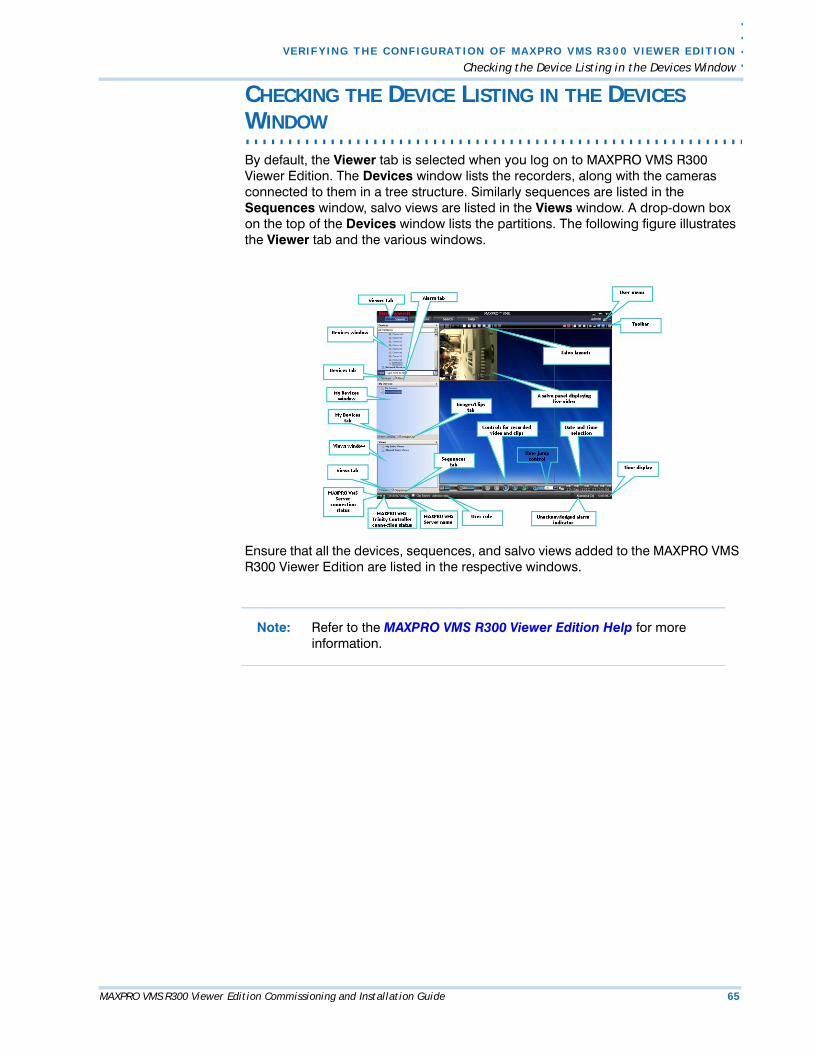
By default, the Viewer tab is selected when you log on to MAXPRO VMS R300 Viewer Edition. The Devices window lists the recorders, along with the cameras connected to them in a tree structure. Similarly sequences are listed in the Sequences window, salvo views are listed in the Views window. A drop-down box on the top of the Devices window lists the partitions. The following figure illustrates the Viewer tab and the various windows.
Ensure that all the devices, sequences, and salvo views added to the MAXPRO VMS R300 Viewer Edition are listed in the respective windows.
Note: Refer to the MAXPRO VMS R300 Viewer Edition Help for more information.
VE R I F Y I N G T H E C O N F I G U RA T I O N O F M A X P R O V M S R 3 0 0 V I E W E R ED I T I O N
Checking the Live Video from Cameras
66 MAXPRO VMS R300 Viewer Edition Commissioning and Installation Guide
5
. . . . . . . . . . . . . . . . . . . . . . . . . . . . . . . . . . . . . . . . . . . . . . . . . . . . . . . . . . .CHECKING THE LIVE VIDEO FROM CAMERAS
To ensure that all the cameras are connected and functioning properly, you need to check for live video from them.
To select the cameras and view live video
• Double-click the camera in the Devices window or My Devices window. You can also drag the camera on a panel in the salvo layout. The panel starts displaying live video and the label Live appears over the video display.
The camera can also be selected using the virtual keyboard and joystick controller. You can select multiple cameras and view live video in different panels of the salvo layout.
Note: Refer to the MAXPRO VMS R300 Viewer Edition Help for more information on how to view live video from cameras.

. .
. .
.
VE R I F Y I NG T H E C O N F I G U RA T I ON O F M A X P R O V M S R 3 0 0 V I EW E R ED I T I O N
Checking the Playback of Recorded Video
MAXPRO VMS R300 Viewer Edition Commissioning and Installation Guide 67
. . . . . . . . . . . . . . . . . . . . . . . . . . . . . . . . . . . . . . . . . . . . . . . . . . . . . . . . . . .CHECKING THE PLAYBACK OF RECORDED VIDEO
To playback video, the recording from the camera must be available and the recording settings for the camera must be configured. You can find out the status of the camera by the colored indicator on the camera icon in the site view. If the indicator on the camera icon is green means the camera is active. If the indicator on the camera is red means it is recording.
Recorded video can be played from the Timeline window. When you select a camera to view video, a timeline corresponding to the camera appears in the Timeline window. The name of the camera appears on the left of the timeline.
To play recorded video from a camera, you can click the timeline at the point from which you want to play video. A timescale is displayed in the lower part of the Timeline window. You can refer to the divisions in the timescale to locate the date and time. You can also select a date and time from which you want to play recorded video using the date and time options in the timeline window.
Color codes are used in the timeline to indicate the availability of video recording for the cameras connected to the IP engine. The time duration for which recording is available is indicated in green color. The time duration for which recording is not available is indicated in white color.
For cameras connected to other recorders such as Rapid Eye, Fusion, Enterprise and Intellex, the color codes are not displayed in the timeline. However, you can click a point in the timeline to play recorded video.
The label Rec is displayed in red color on the panel displaying recorded video from a camera.
Note: For more information on how to play recorded video from the Timeline window and how to use the player controls, refer to the MAXPRO VMS R300 Viewer Edition Help.
VE R I F Y I N G T H E C O N F I G U RA T I O N O F M A X P R O V M S R 3 0 0 V I E W E R ED I T I O N
Checking the Playback Loop in the Timeline Window
68 MAXPRO VMS R300 Viewer Edition Commissioning and Installation Guide
5
CHECKING THE PLAYBACK LOOP IN THE TIMELINE
. . . . . . . . . . . . . . . . . . . . . . . . . . . . . . . . . . . . . . . . . . . . . . . . . . . . . . . . . . .WINDOW
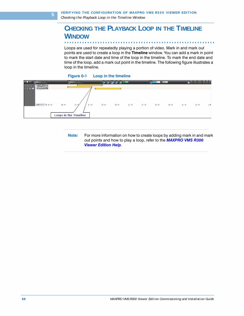
Loops are used for repeatedly playing a portion of video. Mark in and mark out points are used to create a loop in the Timeline window. You can add a mark in point to mark the start date and time of the loop in the timeline. To mark the end date and time of the loop, add a mark out point in the timeline. The following figure illustrates a loop in the timeline.
Figure 0-1 Loop in the timeline
Note: For more information on how to create loops by adding mark in and mark out points and how to play a loop, refer to the MAXPRO VMS R300 Viewer Edition Help.

. .
. .
.
VE R I F Y I NG T H E C O N F I G U RA T I ON O F M A X P R O V M S R 3 0 0 V I EW E R ED I T I O N
Checking the Panning, Tilting, and Zooming
MAXPRO VMS R300 Viewer Edition Commissioning and Installation Guide 69
. . . . . . . . . . . . . . . . . . . . . . . . . . . . . . . . . . . . . . . . . . . . . . . . . . . . . . . . . . .CHECKING THE PANNING, TILTING, AND ZOOMING
In MAXPRO VMS R300 Viewer Edition, you can perform two types of PTZ namely, analog PTZ and Digital PTZ. Using the digital PTZ feature, you can perform panning and tilting on live and recorded video and clips. The digital PTZ feature when enabled allows you to perform panning and tilting on the video display that is zoomed or enlarged in a panel.
You need to perform both analog and digital PTZ on cameras to verify the functioning.
Note: For more information on how to perform analog and digital PTZ, refer to the MAXPRO VMS R300 Viewer Edition Help.

VE R I F Y I N G T H E C O N F I G U RA T I O N O F M A X P R O V M S R 3 0 0 V I E W E R ED I T I O N
Checking the Acknowledgement and Clearing of Alarms
70 MAXPRO VMS R300 Viewer Edition Commissioning and Installation Guide
5
CHECKING THE ACKNOWLEDGEMENT AND CLEARING
. . . . . . . . . . . . . . . . . . . . . . . . . . . . . . . . . . . . . . . . . . . . . . . . . . . . . . . . . . .OF ALARMS
Alarms notify the occurrence of events and event attributes to the operators. You can configure alarms to be triggered when events such as recorder disk space nearing full, motion detection, and others happen. The event attributes that are associated to events are listed in the details of the alarm in Alarm window. The events that trigger an alarm can be selected while configuring the recorders, cameras, and switchers. Events can be associated to event groups.
Each alarm goes through the following states.
New or Unacknowledged
When an alarm is triggered it appears in the Alarm window. You can click the Alarm tab to view the Alarm window. The state of the alarm after it is triggered is referred to as unacknowledged. You can view the list of all the unacknowledged alarms in a table in the Alarm window. The following figure illustrates the Alarm window.
The number of unacknowledged alarms is displayed in a blinking mode in the status bar in red color. For example, Alarms (10) indicate that there are ten unacknowledged alarms. You can select various options using the context menu or shortcut menu by right clicking on the Alarms window. The options include:
• Acknowledge (ACK)
• Clear on ACK
• Show Video
• Show Preview Pane
• Freeze
• Receive Alarms Only
• Receive Events Only
• Receive both Alarms and Events
Acknowledge
An acknowledged alarm indicates that the operator has taken the action. After acknowledging the alarm, it is moved to the acknowledged alarms list in the Alarm window. You can also use the Acknowledge button below Alarms window. To clear acknowledged alarms, use the Clear button below Acknowledged list window.
Clear on ACK
This option clears the alarms which are acknowledged.
Show Video
Select this option if you want to view video from which the alarm was generated.
Show Preview Pane
This option gives you four windows which display alarms which are on, pre-alarm, post alarm, and live alarm videos.
Freeze
Select this option if you no longer wish to receive alarms.
Receive Alarms Only
Select this option if you want to receive only alarms.
Receive Events Only

. .
. .
.
VE R I F Y I NG T H E C O N F I G U RA T I ON O F M A X P R O V M S R 3 0 0 V I EW E R ED I T I O N
Checking the Acknowledgement and Clearing of Alarms
MAXPRO VMS R300 Viewer Edition Commissioning and Installation Guide 71
Select this option if you want to receive only Events.
Receive both Alarms and Events
Select this option receive both alarms and events.
Note: For more information on how to acknowledge and clear alarms, refer to the MAXPRO VMS R300 Viewer Edition Help.

VE R I F Y I N G T H E C O N F I G U RA T I O N O F M A X P R O V M S R 3 0 0 V I E W E R ED I T I O N
Checking the Creation of Images
72 MAXPRO VMS R300 Viewer Edition Commissioning and Installation Guide
5
. . . . . . . . . . . . . . . . . . . . . . . . . . . . . . . . . . . . . . . . . . . . . . . . . . . . . . . . . . .CHECKING THE CREATION OF IMAGES
A frame of video displayed in the panel can be saved as an image. The image can be saved in Bitmapped Graphics (BMP), Joint Photographic Experts Group (JPG) format, Portable Graphics format (PNG), and Graphics Interchange Format (GIF).
Only the images saved in the ImagesAndClips folder at the location in the hard drive in which MAXPRO VMS R300 files are installed can be viewed in the Image/ Clip window. You can double-click the image view option in the Image/Clip window to view images on the salvo layout. You can also select the image size large, medium, and small as per the requirement.
For example, X:\ProgramFiles\Honeywell\TrinityFramework\ImagesAndClips. Here, X: is the disk drive.
The images can also be saved in other folders on the computer.
Note: For more information on how to save and view images, refer to the MAXPRO VMS R300 Viewer Edition Help.

. .
. .
.
VE R I F Y I NG T H E C O N F I G U RA T I ON O F M A X P R O V M S R 3 0 0 V I EW E R ED I T I O N
Checking the Creation of Clips
MAXPRO VMS R300 Viewer Edition Commissioning and Installation Guide 73
. . . . . . . . . . . . . . . . . . . . . . . . . . . . . . . . . . . . . . . . . . . . . . . . . . . . . . . . . . .CHECKING THE CREATION OF CLIPS
Clips can be created from recorded video and saved in MP4, MPG, AVI, and WMV format depending on the format supported by the recorders. Only the clips saved in the ImagesAndClips folder at the location in the hard drive in which MAXPRO VMS R300 files are installed can be viewed in the Image/ Clip window.
For example, X:\ProgramFiles\Honeywell\TrinityFramework\ImagesAndClips. Here, X: is the hard drive.
The clips can also be saved in other folders on the computer.
The clips can be saved with digital signatures. Digital signatures ensure authenticity of clips. Digital signatures are primarily used to authenticate videos that are produced in courts as evidence. A digital signature generates a unique string for the clip using algorithms recommended by the World Wide Web Consortium (W3C) standards. If the video in the clip is modified, a verification check for the unique string fails indicating that the content is tampered. When a clip is saved with the digital signature, a package file with the.PKG extension is created to save the clip.
Note: For more information on how to save and view images, refer to the MAXPRO VMS R300 Viewer Edition Help.
A salvo layout that is customized based on the preferences of the operators is referred to as a salvo view. Cameras and sequences that are selected frequently and the preferred salvo layout can be saved as a salvo view. The saved salvo views appear in the Views window.

VE R I F Y I N G T H E C O N F I G U RA T I O N O F M A X P R O V M S R 3 0 0 V I E W E R ED I T I O N
Checking the Device Listing in My Devices Window
74 MAXPRO VMS R300 Viewer Edition Commissioning and Installation Guide
5
CHECKING THE DEVICE LISTING IN MY DEVICES
. . . . . . . . . . . . . . . . . . . . . . . . . . . . . . . . . . . . . . . . . . . . . . . . . . . . . . . . . . .WINDOW
In the My Devices window, operators can group the video sources, which are frequently selected such as cameras, monitors, and sequences. If you group the video sources, it is easy to select and you need not search in the Devices window, which generally consists of many video sources. You can also group the devices under shared devices. Devices grouped under shared devices are displayed on all client workstations irrespective of the logged in user.
Note: For more information on how to add a video source to My Devices window and how to create folders to group them, refer to the MAXPRO VMS R300 Viewer Edition Help.


© 2012 Honeywell International Inc. All rights reserved. No part of this publication may be reproduced by any means without written permission from Honeywell Video Systems. The information in this publication is believed to be accurate in all respects. However, Honeywell Video Systems cannot assume responsibility for any consequences resulting from the use thereof. The information contained herein is subject to change without notice. Revisions or new editions to this publication may be issued to incorporate such changes.
Document 800-11111 – Rev A – 1/2012
Honeywell Video Systems (Head Office)2700 Blankenbaker Pkwy, Suite 150Louisville, KY 40299, USAwww.honeywellvideo.com +1.800.796.2288
Honeywell Security Australia Pty Ltd.Unit 5, Riverside Centre, 24-28 River Road WestParramatta, NSW 2150, Australiawww.honeywellsecurity.com/au +61.2.8837.9300
Honeywell Security Asia Pacific33/F Tower A, City Center, 100 Zun Yi RoadShanghai 200051, Chinawww.asia.security.honeywell.com +86 21.2527.4568
Honeywell Security AsiaFlat A, 16/F, CDW Building, 388 Castle Peak RoadTsuen Wan, N.T., Hong Kongwww.asia.security.honeywell.com +852.2405.2323
Honeywell Security FranceParc Gutenberg, 8, Voie La Cardon91120, Palaiseau, Francewww.honeywell.com/security/fr +33.01.64.53.80.40
Honeywell Security Italia SpAVia Treviso 2 / 431020 San VendemianoTreviso, Italywww.honeywell.com/security/it +39.04.38.36.51
Honeywell Security EspañaMijancas 1. 3a PlantaP.Ind. Las Mercedes28022 Madrid, Spainwww.honeywell.com/security/es +34.902. 667.800
Honeywell Video Systems Northern EuropeNetwerk 1211446 WV Purmerend, The Netherlandswww.honeywell.com/security/nl +31.299.410.200
Honeywell Systems GroupAston Fields Road, Whitehouse Ind EstRuncorn, Cheshire, WA7 3DL, UKwww.honeywell.com/security/uk +44 (0)1928 756999
Honeywell Security South AfricaUnit 6 Galaxy Park, 17 Galaxy AvenueLinbro Park, P.O. Box 599042100 Kengray, Johannesburg, South Africawww.honeywell.co.za +27.11.574.2500
Honeywell Security DeutschlandJohannes-Mauthe-Straße 14D-72458 Albstadt, Germanywww.security.honeywell.com/de +49.74 31.8 01.0
Honeywell Security PolandChmielewskiego 22a, 70-028Szczecin, Polskawww.ultrak.pl +48.91.485.40.60
Honeywell Security Czech RepublicHavránkova 33, BrnoDolní Heršpice, 619 00, Czech Republicwww.olympo.cz +420.543.558.111
Honeywell Security Slovakia RepublicVajnorská 142, 83104 BratislavaSlovakiawww.olympo.sk +421.2.444.54.660