
Commencement of Commercial Operation of All Four Units ...
21
Social Infrastructure Power Systems 22 TOSHIBA REVIEW Science and Technology Highlights 2017 Social Infrastructure Power Systems Commencement of Commercial Operation of All Four Units Supplied to Qingyuan Pumped Storage Power Station, China The Qingyuan Pumped Storage Power Station of China Southern Power Grid Co., Ltd. has four pumped storage units with a pumping head of more than 500 m and a capacity of 320 MW. The final pumped storage unit to be completed at this facility started commercial operation in August 2016. Toshiba Hydro Power (Hangzhou) Co., Ltd. (THPC), a subsidiary of Toshiba in China, supplied the four main units and various balance-of-plant (BOP) systems and provided instructions on installation. The pump-turbines and generator-motors were jointly designed by Toshiba and THPC, and most of their com- ponents were fabricated by THPC to achieve local manu- facturing of the pumped storage units. THPC purchased and supplied most of the BOP systems, including the supervisory control system, protection systems, speed governors, excitation systems, and various electromechani- cal systems such as a static starter, main-circuit equipment, switchgears, station service power supply systems, an emergency diesel generation system, draft gate systems, water supply systems, oil pressure systems, compressed air systems, valves, and piping. The commissioning tests of the entire power station were jointly conducted by Toshiba and THPC. For the successful management of this large project by THPC, including procurement engineering of the BOP systems and implementation of the commissioning tests, Toshiba transferred its extensive expertise cultivated during its long history to THPC. A splitter runner consisting of long and short blades was employed to reduce pressure fluctuations and vibration, even during partial-load operation. A ring rim made of a thick steel plate suitable for high-speed machines was utilized for the generator-motor rotors. The conditions of the water conduit system were unusu- ally severe, with a single water conduit diverging into four units for both the upstream and downstream sections of the system without an upstream surge tank. In order to avoid problems under such severe conditions, we performed a large number of simulation calculations to develop methods for plant operation and pump-turbine control. In addition, we successfully conducted a simultaneous load rejection test on all four units, the first time that this has ever been achieved at a pumped storage power station in China ( * ) . The ratings of the pump-turbines and generator-motors are as follows: • Pump-turbines: 326.5 MW-470 m/509.08 m-428.6 min -1 , 4 units • Generator-motors: 356 MVA-15.75 kV-428.6 min -1 , 4 units. ( * ) As of August 2016 (as researched by Toshiba) Qingyuan Pumped Storage Power Station, China Splitter runner Generator-motor Immediately before load rejection, with red operation lamps on all four units illuminated Simultaneous load rejection test on all four units
Transcript of Commencement of Commercial Operation of All Four Units ...
Social Infrastructure Power System
s
22 TOSHIBA REVIEW Science and Technology Highlights 2017
Social Infrastructure Power Systems
Commencement of Commercial Operation of All Four Units Supplied to Qingyuan Pumped Storage Power Station, China
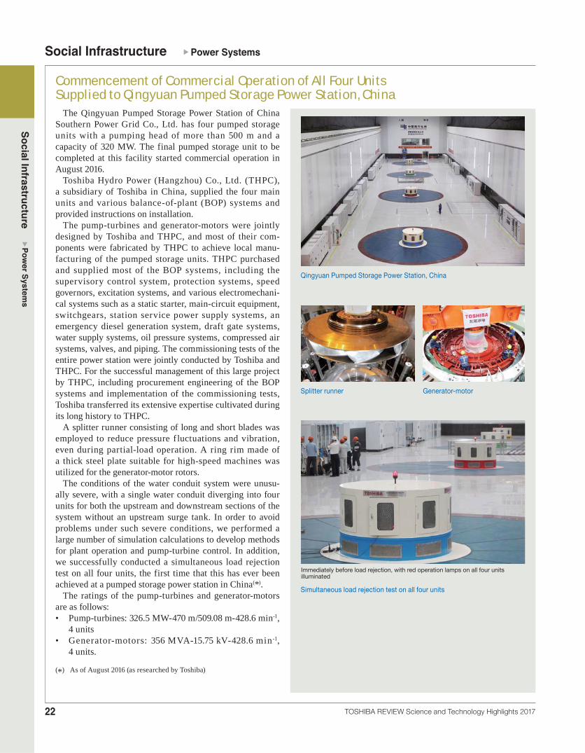
The Qingyuan Pumped Storage Power Station of China Southern Power Grid Co., Ltd. has four pumped storage units with a pumping head of more than 500 m and a capacity of 320 MW. The final pumped storage unit to be completed at this facility started commercial operation in August 2016.
Toshiba Hydro Power (Hangzhou) Co., Ltd. (THPC), a subsidiary of Toshiba in China, supplied the four main units and various balance-of-plant (BOP) systems and provided instructions on installation.
The pump-turbines and generator-motors were jointly designed by Toshiba and THPC, and most of their com-ponents were fabricated by THPC to achieve local manu-facturing of the pumped storage units. THPC purchased and supplied most of the BOP systems, including the supervisory control system, protection systems, speed governors, excitation systems, and various electromechani-cal systems such as a static starter, main-circuit equipment, switchgears, station service power supply systems, an emergency diesel generation system, draft gate systems, water supply systems, oil pressure systems, compressed air systems, valves, and piping. The commissioning tests of the entire power station were jointly conducted by Toshiba and THPC. For the successful management of this large project by THPC, including procurement engineering of the BOP systems and implementation of the commissioning tests, Toshiba transferred its extensive expertise cultivated during its long history to THPC.
A splitter runner consisting of long and short blades was employed to reduce pressure f luctuations and vibration, even during partial-load operation. A ring rim made of a thick steel plate suitable for high-speed machines was utilized for the generator-motor rotors.
The conditions of the water conduit system were unusu-ally severe, with a single water conduit diverging into four units for both the upstream and downstream sections of the system without an upstream surge tank. In order to avoid problems under such severe conditions, we performed a large number of simulation calculations to develop methods for plant operation and pump-turbine control. In addition, we successfully conducted a simultaneous load rejection test on all four units, the first time that this has ever been achieved at a pumped storage power station in China(*).
The ratings of the pump-turbines and generator-motors are as follows:• Pump-turbines: 326.5 MW-470 m/509.08 m-428.6 min-1,
4 units• Generator-motors: 356 MVA-15.75 kV-428.6 min-1,
4 units.
(*) As of August 2016 (as researched by Toshiba)
Qingyuan Pumped Storage Power Station, China
Splitter runner Generator-motor
Immediately before load rejection, with red operation lamps on all four units illuminated
Simultaneous load rejection test on all four units

23
Social Infrastructure Power System
s
TOSHIBA REVIEW Science and Technology Highlights 2017
Commencement of Commercial Operation of Daini Yabukami Hydroelectric Power Station in Niigata Prefecture
The Yabukami Hydroelectric Power Station of Tohoku Electric Power Co., Inc., located at the Yabukami Reservoir in Niigata Prefecture, had customarily been discharging extra water from the gate when influent water exceeded the amount of its water consumption. In order to use the discharged water effectively, the newly built Daini Yabukami Hydroelectric Power Station commenced com-mercial operation in June 2016.
At the Daini Yabukami Hydroelectric Power Station, Toshiba installed a vertical-shaft bulb type turbine, which has been used in only a few power plants in the world. In order to simplify the overall facilities, the guide-vane and runner-vane control systems are equipped with a hybrid servo-motor system that directly pressurizes a closed oil supply loop with a two-way oil pump.
We increased the generator output by improving the tur-bine efficiency through a turbine model test. The ratings of the turbine and generator are as follows:• Turbine: 4.89 MW-17.85 m-300 min-1
• Generator: 4.98 MVA-6.6 kV-300 min-1.Installation of water turbine at Daini Yabukami Hydroelectric Power Station of Tohoku Electric Power Co., Inc.
Commencement of Commercial Operation of All Three Units of Nam Ou Stage 5 Hydro Power Plant, Laos
All three units of the vertical-shaft Francis turbines and generators at the Nam Ou Stage 5 Hydro Power Plant in Laos, which were supplied by THPC, commenced com-mercial operation in May 2016.
Since these turbines have a very low head for Francis type units, Toshiba used advanced computational f luid dynamics (CFD) analysis for their hydraulic design in order to achieve stable operation with low vibration and low noise. In addition, friction couplings were utilized for the connection of the runner and the main shaft in order to reduce assembly time.
The ratings of the turbines and the generators are as fol-lows:• Turbines: 83 MW-49 m-125 min-1
• Generators: 91.43 MWA-11 kV-125 min-1-50 Hz. Nam Ou Stage 5 Hydro Power Plant, Laos
Social Infrastructure Power System
s
24 TOSHIBA REVIEW Science and Technology Highlights 2017
Completion of In-Factory Manufacture of Generator for San Agaton Powerplant Unit 2, Venezuela
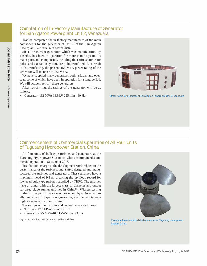
Toshiba completed the in-factory manufacture of the main components for the generator of Unit 2 of the San Agaton Powerplant, Venezuela, in March 2016.
Since the current generator, which was manufactured by Toshiba, has been in operation for more than 35 years, its major parts and components, including the entire stator, rotor poles, and excitation system, are to be retrofitted. As a result of the retrofitting, the present 158 MVA power rating of the generator will increase to 182 MVA.
We have supplied many generators both in Japan and over-seas, some of which have been in operation for a long period. We will actively retrofit these generators.
After retrofitting, the ratings of the generator will be as follows:• Generator: 182 MVA-13.8 kV-225 min-1-60 Hz. Stator frame for generator of San Agaton Powerplant Unit 2, Venezuela
Commencement of Commercial Operation of All Four Units of Tugutang Hydropower Station, China
All four units of bulb type turbines and generators at the Tugutang Hydropower Station in China commenced com-mercial operation in September 2016.
Toshiba took charge of the development work related to the performance of the turbines, and THPC designed and manu-factured the turbines and generators. These turbines have a maximum head of 9.8 m, breaking the previous record for low-head bulb type turbines supplied by THPC. The turbines have a runner with the largest class of diameter and output for three-blade runner turbines in China(*). Witness testing of the turbine performance was carried out by an internation-ally renowned third-party organization, and the results were highly evaluated by the customer.
The ratings of the turbines and generators are as follows:• Turbines: 22.5 MW-7.3 m-75 min-1
• Generators: 25 MVA-10.5 kV-75 min-1-50 Hz.
(*) As of October 2016 (as researched by Toshiba) Prototype three-blade bulb turbine runner for Tugutang Hydropower Station, China

25
Social Infrastructure Power System
s
TOSHIBA REVIEW Science and Technology Highlights 2017
Completion of New Casting Foundry at THPCTHPC commenced operation of a new casting foundry
in March 2016.Refined stainless steel cast components are often
required for hydroelectric generating facilities. In order to fulfill such requirements, we have installed refine-ment facilities including a ladle furnace (LF)(*1) and a vacuum oxygen decarburization (VOD) furnace(*2) in the new foundry to manufacture high-quality stainless steel castings. This also makes it possible to manu-facture high-quality alloy steels for thermal power plant applications. The new foundry is equipped with auxiliary facilities as well. As a result, it has an annual capacity of 7 000 tons of castings.
(*1) A furnace for desulfurization and removal of inclusions in molten steel. Molten steel is transferred from an electric arc furnace to a ladle and heated.
(*2) A furnace for the fast decarburization reaction with oxygen gas in a vacuum vessel
VOD furnace LF furnace
New foundry shop, and LF and VOD systems
Repair of Existing LP Steam Turbine Rotors at Fukuyama Joint Power Station and Kurashiki Joint Power Station of Setouchi Joint Thermal Power Co., Ltd.
The existing six 156 MW steam turbine units of Setouchi Joint Thermal Power Co., Ltd. were manufac-tured by Toshiba. As these units have been in operation for more than 40 years, it is becoming important to maintain their reliability. In particular, the low-pressure (LP) steam turbine rotors need to be safeguarded against aging deterioration. It is difficult, however, to repair LP rotors during the short outage period for periodic inspections.
To resolve this issue, we focused on the interchange-ability of the rotors of the six units of the same design and proposed a scheme for sharing the use of the exist-ing LP rotors among the six units. Under this scheme, first the rotor of one unit is replaced with a new rotor. The old rotor is then fitted with new blades for reuse in another unit. This process is repeated for all units, reducing the cost and time required for on-site work.
The customer agreed with our proposal and awarded us a contract for repairing the LP rotors of four of the six units. In 2016, we completed the repair of the LP rotor for Kurashiki Joint Power Station Unit 3.
Fukuyama Joint Power Station
FY2015New LP rotor installed FY2016
FY2015Existing LP rotor repaired
Kurashiki Joint Power Station
Unit 3 Unit 4 Unit 5Unit 4 Unit 5 Unit 6
New LP rotor
: The old rotor will be fitted with new blades and reused in another unit.
LP rotor HIP rotor
HIP: high- to intermediate-pressure
, , ,
Plan for sequential repair of LP steam turbine rotors of Setouchi Joint Thermal Power Co., Ltd.
Social Infrastructure Power System
s
26 TOSHIBA REVIEW Science and Technology Highlights 2017
Commercial Operation of Sakaide Thermal Power Station Unit 2 of Shikoku Electric Power Co., Inc. in Kagawa Prefecture
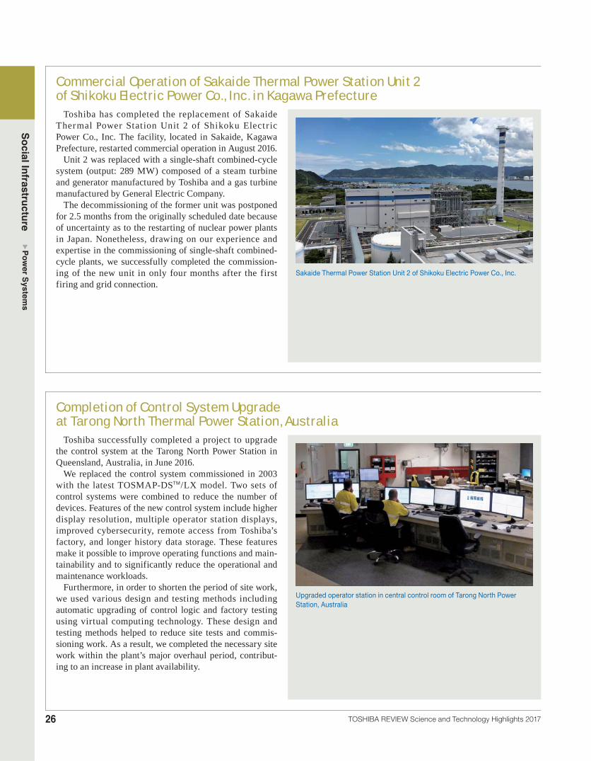
Toshiba has completed the replacement of Sakaide Thermal Power Station Unit 2 of Shikoku Electr ic Power Co., Inc. The facility, located in Sakaide, Kagawa Prefecture, restarted commercial operation in August 2016.
Unit 2 was replaced with a single-shaft combined-cycle system (output: 289 MW) composed of a steam turbine and generator manufactured by Toshiba and a gas turbine manufactured by General Electric Company.
The decommissioning of the former unit was postponed for 2.5 months from the originally scheduled date because of uncertainty as to the restarting of nuclear power plants in Japan. Nonetheless, drawing on our experience and expertise in the commissioning of single-shaft combined-cycle plants, we successfully completed the commission-ing of the new unit in only four months after the first firing and grid connection.
Sakaide Thermal Power Station Unit 2 of Shikoku Electric Power Co., Inc.
Completion of Control System Upgrade at Tarong North Thermal Power Station, Australia
Toshiba successfully completed a project to upgrade the control system at the Tarong North Power Station in Queensland, Australia, in June 2016.
We replaced the control system commissioned in 2003 with the latest TOSMAP-DSTM/LX model. Two sets of control systems were combined to reduce the number of devices. Features of the new control system include higher display resolution, multiple operator station displays, improved cybersecurity, remote access from Toshiba’s factory, and longer history data storage. These features make it possible to improve operating functions and main-tainability and to significantly reduce the operational and maintenance workloads.
Furthermore, in order to shorten the period of site work, we used various design and testing methods including automatic upgrading of control logic and factory testing using virtual computing technology. These design and testing methods helped to reduce site tests and commis-sioning work. As a result, we completed the necessary site work within the plant’s major overhaul period, contribut-ing to an increase in plant availability.
Upgraded operator station in central control room of Tarong North Power Station, Australia

27
Social Infrastructure Power System
s
TOSHIBA REVIEW Science and Technology Highlights 2017
Shipment of Steam Turbine and Generator for Kizildere III Geothermal Power Plant Unit 1, Turkey
In October 2016, Toshiba shipped a steam turbine and generator for Kizildere III Geothermal Power Plant Unit 1 being constructed by the Zorlu Energy Group, one of the largest independent power producers in Turkey. Unit 1 of the Kizildere III Geothermal Power Plant is a geothermal combined-cycle unit (GCCU) consisting of a flash steam turbine system that directly uses high-temperature geother-mal steam and an organic Rankine cycle (ORC) turbine system that uses geothermal fluid at lower temperature.
The steam turbine and generator have an output of 72 MW, and the total output of the GCCU, including the ORC turbine and generator, is 95 MW. Commercial opera-tion is scheduled to start in October 2017.
We will continue to provide support for the smooth prog-ress of construction and commissioning of this facility. We have also received an order for a steam turbine and genera-tor for Unit 2 of Kizildere III, for delivery in August 2017.
Steam turbine rotor for Kizildere III Geothermal Power Plant Unit 1, Turkey
Increase in Capacity of Hydrogen-Cooled GeneratorsManufacturers of turbine generators select the most
suitable cooling method from among air cooling, hydrogen cooling, and stator winding water cooling according to the capacity of the generator. In 1999, Toshiba developed a high-thermal-conductivity (HTC) insulation technol-ogy that provides double the thermal conductivity for the ground insulation of stator windings compared with the conventional technology. Since then, we have applied this technology to hydrogen-cooled generators and increased the applicable capacity range.
The efficiency of an indirectly hydrogen-cooled genera-tor is 0.1 to 0.2% higher than that of a stator water-cooled generator of the same capacity. Our hydrogen-cooled generators have achieved an efficiency exceeding 99.1% in shop tests. A 563.334 MVA generator and a 670 MVA generator incorporating HTC insulation technology started commercial operation in 2007 and 2010, respectively, and have since been in successful operation.
We have been making efforts to increase the capacity of hydrogen-cooled generators. As a result of continuous improvements and proven technologies, hydrogen cooling can now be applied to 1 000 MVA-class generators. We will apply hydrogen cooling to large-capacity generators for combined-cycle and coal-fired power stations.
Air-cooled1999 Hydrogen-
cooled Stator winding water-cooled
Air-cooled2016 Hydrogen-cooled Stator winding water-cooled
Generator capacity (MVA)0 200 400 600 800 1 000 1 200
Development and application of HTC insulation
Year
Trends in generator cooling methods and power generation capacity ranges
Photo provided by The Kansai Electric Power Co., Inc.
670 MVA hydrogen-cooled generator

Social Infrastructure Power System
s
28 TOSHIBA REVIEW Science and Technology Highlights 2017
Completion of Generator Stator Rewinding at Joffre Cogeneration Plant in Canada
Toshiba America Energy Systems Corporation and Toshiba Corporation were awarded a contract in May 2015 to rewind the generator stator for the Joffre Cogeneration Plant in Alberta, Canada. We shipped the stator coils and associated winding components in November 2015, and completed the stator rewinding at the Joffre site in June 2016.
We applied the latest technologies to this project. For example, a special winding method was used to reduce the maximum interphase voltage at the coil end and thereby suppress corona discharge. A high-performance insulating material was also employed to satisfy the severe voltage endurance testing requirements.
Prior to the on-site stator rewinding, we successfully con-ducted a voltage endurance test on sample coils under high-voltage and high-temperature conditions in accordance with IEEE standards at an external testing laboratory in Canada.
We will continue to meet stringent customer requirements for the servicing of our generators.
IEEE: Institute of Electrical and Electronics Engineers
Generator stator rewinding at Joffre Cogeneration Plant, Canada
Completion of Heat Recovery Steam Generator Installation and Hydrostatic Test at Nishi-Nagoya Thermal Power Plant Group No. 7 of Chubu Electric Power Co., Inc.
Toshiba is constructing Group No. 7 of the Nishi-Nagoya Thermal Power Plant operated by Chubu Electric Power Co., Inc. This multishaft combined-cycle plant is expected to become one of the world’s highest efficiency thermal power plants.
We installed six heat recovery steam generators (HRSGs), which generate steam using exhaust gas from the gas turbines, at the plant from May 2016 through January 2017. Each HRSG was constructed in the form of three large modules and transported to the site by sea.
The first unit, named 7-1(A), was installed in June 2016 and passed a hydrostatic pressure test in mid-October after the completion of piping installation work. The construction of units 7-1(B) and 7-1(C) is in progress. The gas turbine was fired in March 2017, as scheduled.
7-1(A) HRSG for Nishi-Nagoya Thermal Power Station Group No. 7 of Chubu Electric Power Co., Inc.

29
Social Infrastructure Power System
s
TOSHIBA REVIEW Science and Technology Highlights 2017
Order Received for 300 MW-Class Ultra-Supercritical Steam Turbine Generator
Toshiba has received an order for a steam turbine generator for the Lontar Coal-Fired Thermal Power Plant Expansion Project in Java, Indonesia, which is being constructed by Perusahaan Listrik Negara (PLN), Indonesia’s state-owned electricity company.
The new turbine generator with a rated output of 315 MW will start commercial operation in 2019. The steam turbine operates at 50 Hz and is designed in a tandem compound double-f low exhaust configuration. The most noteworthy feature of this unit is its operation under ultra-supercritical steam conditions despite its small capacity.
The efficiency of the high-pressure section of small-capac-ity units is significantly lower than that of large-capacity units. This is one of the reasons why there are only a small number of small-capacity ultra-supercritical steam turbines. Although the thermal efficiency of a power plant increases at high pressure and high temperature, the steam turbine effi-ciency in the high-pressure section decreases, so the overall power plant efficiency does not improve as expected.
To overcome this problem, we drew on our extensive turbine technologies accumulated through our experience with many large power plants. As a result, the efficiency of our new small-capacity turbine is sufficiently high to benefit from ultra-supercritical operation.
Cross-sectional outline of small-capacity steam turbine for ultra-supercritical coal-fired power generation plant
Shipment of Turbine for World’s First Direct-Fired Supercritical CO2 Cycle Demonstration Power Plant to U.S.
Toshiba has been developing a turbine and a combustor for supercritical carbon dioxide (CO2) cycle power plants that operate at high efficiency and collect high-pressure CO2. We have shipped this turbine to a 25 MWe demonstration plant being constructed in Texas, U.S.A. by NET Power, LLC.
We designed and manufactured the world’s first direct-fired supercritical CO2 turbine(*) by combining casing tech-nology for ultra-supercritical steam turbines with material and cooling technologies for high-temperature gas turbines. This turbine will operate at a turbine inlet pressure of 30 MPa and a turbine inlet temperature of 1 150°C, a combi-nation that substantially exceeds past records. We conducted a combustion test of the combustor at a pressure of 30 MPa and successfully completed it in November 2015.
(*) As of December 2016 (as researched by Toshiba)
25 MWe supercritical CO2 turbine assembly for pilot plant

Social Infrastructure Power System
s
30 TOSHIBA REVIEW Science and Technology Highlights 2017
Completion of Installation of Commercial CCU System at Saga Incineration Plant
In September 2016, Toshiba completed the world’s first com-mercial-use carbon capture and utilization (CCU) system(*) at a municipal waste incineration plant in Saga, Japan. The CCU system can capture 10 tons of CO2 per day from the flue gas of the incinerator. The captured CO2 is being sold to businesses for use in crop cultivation and algae culture.
We installed a small-scale experimental CCU system at the Saga plant in October 2013. The test findings confirmed that the CCU system’s separation and capture mechanism operated satisfactorily with the flue gas impurities specific to the plant. Based on the experience gained with the new CCU system and a pilot plant constructed in the city of Omuta, Japan, we will continue to promote the expansion of high-performance capture technology and its application to the global market.
(*) As of September 2016 (as researched by Toshiba)
CO2 storage tankAbsorber
Stripper
CCU system installed at municipal waste incineration plant in Saga City
Commencement of Construction of Large-Scale Carbon Capture Demonstration Facility
Toshiba, Mizuho Information & Research Institute, Inc., and 11 other entities have been selected to implement the “Sustainable CCS Project” sponsored by the Ministry of the Environment of Japan. The consortium led by the two companies will construct a large-scale carbon capture facility to capture CO2 emitted by a thermal power plant, and will evaluate the technology’s performance, cost, and environmen-tal impact. The project will run from 2016 to 2020, and the consortium will use the results obtained to develop policies and measures to facilitate carbon capture and storage (CCS) deployment.
We will construct the carbon capture facility at the Mikawa Power Plant (capacity: 50 MW) operated by Sigma Power Ariake Co., Ltd., a Toshiba subsidiary, in the city of Omuta, Fukuoka Prefecture. The facility is designed to capture more than 500 tons of CO2 per day, equivalent to more than half of the daily emissions from the Mikawa Power Plant.
The Mikawa Power Plant was retrofitted in April 2017 to accommodate both coal- and biomass-fired power generation. When the demonstration facility is completed in 2020, it will become the world’s first BECCS(*1) power plant equipped with a large-scale carbon capture demonstration facility capable of capturing CO2 from a biomass power plant(*2). This BECCS technology offers the possibility of reducing the amount of CO2 in the atmosphere by capturing CO2 from f lue gas produced by the combustion of palm kernel shells that have absorbed atmospheric CO2 during their process of growth.
(*1) BECCS: bioenergy with carbon capture and storage(*2) As of June 2017 (as researched by Toshiba)
Rendering of CO2 capture demonstration plant

31
Social Infrastructure Power System
s
TOSHIBA REVIEW Science and Technology Highlights 2017
Delivery of Heavy-Ion Radiotherapy System to Kanagawa Cancer Center
In March 2016, Toshiba completed the delivery of a heavy-ion radiotherapy system to the i-ROCK (Ion-beam Radiation Oncology Center in Kanagawa) facility at the Kanagawa Cancer Center.
Heavy-ion radiotherapy is a cancer treatment that irradiates tumor tissues in a patient with an accelerated carbon-ion beam. It causes less damage to surrounding healthy tissues and can kill cancer cells more efficiently than conventional radiotherapy.
Our heavy-ion radiotherapy system provides scanning irradiation in all treatment rooms of the facility for the first time in Japan(*). The target tumor is scanned in a zigzag pattern with a sharp ion beam whose size is controlled to a diameter of 3 mm or less, enabling precise irradiation accord-ing to the shape of the target tumor. Moreover, the scanning speed reaches a maximum of 100 mm/ms while the ion beam accurately tracks changes in the position of a tumor caused by respiratory motion.
Since all of the treatment rooms are equipped with com-puted tomography (CT) devices, CT scans can be performed before and after irradiation without changing the posture of the patient on a robotic couch.
As of the end of May 2017, 213 patients had been treated at i-ROCK. We will continue to develop and deliver this cutting-edge heavy-ion radiotherapy system to medical institutions worldwide.
(*) As of May 2017 (as researched by Toshiba)
Treatment room of i-ROCK
i-ROCK facility at the Kanagawa Cancer Center
Synchrotron accelerator Four treatment rooms
Internal layout of i-ROCK

Social Infrastructure Power System
s
32 TOSHIBA REVIEW Science and Technology Highlights 2017
Significant Reduction Achieved in Dose Rate on Operating Floor of Reactor Building of Fukushima Daiichi Nuclear Power Station Unit 3
The reactor building of Unit 3 of the Fukushima Daiichi Nuclear Power Station was damaged by hydrogen explosions in the wake of the Great East Japan Earthquake. As a result, the entire operating f loor of Unit 3 was contaminated by highly radioactive substances released from the reactor.
The dose rate on the operating floor exceeded 100 mSv/h in some spots. The spent fuel pool on the operating floor was filled with spent fuel, and the retrieval of this fuel was a high-priority issue. However, in order for human workers to begin fuel removal work, the dose rate had to be reduced to less than 1 mSv/h. In addition, new technologies and equipment had to be developed because of the damage to the building structure and various modes of contamination.
Due to the limited load tolerance of the structure and the high dose rate on the floor, various types of equipment with specialized decontamination functions were developed that could be remotely operated while being suspended by cranes. The decontamination functions included vacuuming up rubble left on the floor surface, scabbling using ultrahigh-pressure water to remove contamination that had penetrated into the concrete f loor, and dissolving contamination on metal materials using chemical agents.
In order to prioritize highly contaminated areas and improve the efficiency of the dose reduction work, gamma cameras and a dose rate analysis system were utilized to measure and analyze radioactive contamination. As a result, we succeeded in significantly reducing the dose rate on the operating floor of Unit 3. Additionally, we successfully reduced the dose rate in the manned working area to less than 1 mSv/h using floor shields.
All photos provided by Tokyo Electric Power Company Holdings, Inc.
Previously shielded areaPreviously shielded area
Decontaminated areaDecontaminated area
Operating floor of Fukushima Daiichi Nuclear Power Station Unit 3 covered with collapsed building frames after Great East Japan Earthquake (before removal of large debris)
Operating floor of Fukushima Daiichi Nuclear Power Station Unit 3 covered with iron shields in November 2016 (partially not covered)
Operating floor of Fukushima Daiichi Nuclear Power Station Unit 3 after debris removal and decontamination in March 2016 (shields partially installed in advance)
Decontamination and shielding work on operating floor of Fukushima Daiichi Nuclear Power Station Unit 3
33
Social Infrastructure Power System
s
TOSHIBA REVIEW Science and Technology Highlights 2017
Wearable System to Support Remote Field OperationsWorkers at the Fukushima Daiichi Nuclear Power Station
and other nuclear power plants must be protected while working in areas with high radiation and contamination levels. Workers at nuclear power plants are required to wear a full-face mask, rubber gloves, and other protec-tive gear. Nevertheless, tasks must be completed by the minimum number of workers in a limited period of time. Because of the protective gear, these workers have dif-ficulty in communicating with supervisors, engineers, and designers working in remote locations.
To support on-site workers, Toshiba has developed a field support system that provides hands-free communica-tion. This system employs wearable devices, including smart glasses, a camera, and a headset, so that workers and supervisors can communicate with each other via video and voice during on-site work. In September 2016, we demonstrated the feasibility of this system for practi-cal use in a verification test conducted at the Fukushima Daiichi Nuclear Power Station.
Wearable system for highly contaminated areas
Remote locations
Supervisor
Engineers and designersWorker
Site
Headset
Smart glasses
Camera
Dosimeter
Informationterminal
Indoor positioning sensor
Outline of field support system employing wearable devices with hands-free communication capability
Underwater Robot for Investigation of PCV of Fukushima Daiichi Nuclear Power Station Unit 3
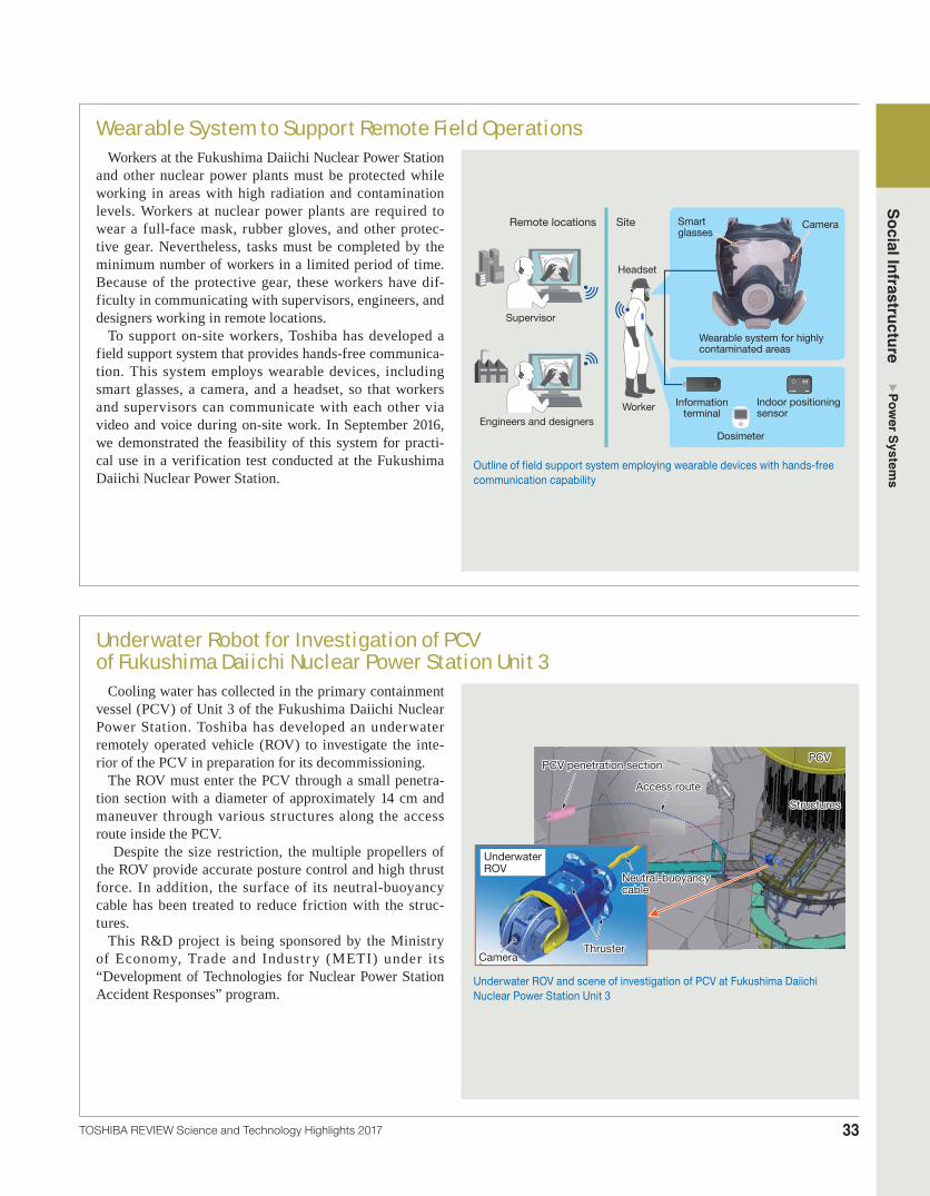
Cooling water has collected in the primary containment vessel (PCV) of Unit 3 of the Fukushima Daiichi Nuclear Power Station. Toshiba has developed an underwater remotely operated vehicle (ROV) to investigate the inte-rior of the PCV in preparation for its decommissioning.
The ROV must enter the PCV through a small penetra-tion section with a diameter of approximately 14 cm and maneuver through various structures along the access route inside the PCV.
Despite the size restriction, the multiple propellers of the ROV provide accurate posture control and high thrust force. In addition, the surface of its neutral-buoyancy cable has been treated to reduce friction with the struc-tures.
This R&D project is being sponsored by the Ministry of Economy, Trade and Industry (METI) under its “Development of Technologies for Nuclear Power Station Accident Responses” program.
PCVPCV
Access routeAccess route
PCV penetration sectionPCV penetration section
StructuresStructures
Underwater ROV
Neutral-buoyancy cableNeutral-buoyancy cable
CameraCameraThrusterThruster
Underwater ROV and scene of investigation of PCV at Fukushima Daiichi Nuclear Power Station Unit 3

Social Infrastructure Power System
s
34 TOSHIBA REVIEW Science and Technology Highlights 2017
Modification of MRRSTM Cross-Flow Filtration System for Fukushima Daiichi Nuclear Power Station
The pretreatment system of the MRRSTM (Multi-radionuclide Removal System) facility at the Fukushima Daiichi Nuclear Power Station precipi-tates out calcium and other elements that inhibit strontium absorption as carbonate slurry. This process utilizes filters equipped with backwashing devices in order to suppress fouling. However, several problems have occurred, including defor-mation of filter gaskets due to backpressure and damage to piston seals of the backwashing devices due to the adhesion of slurry.
To solve these problems, Toshiba has developed a filtration system equipped with enhanced filter gaskets that tolerate backpressure as well as back-washing devices with a modified resin piston. We have verified that the new filtration system has a durability of 150 000 backwashing cycles, which is equivalent to three years of operation. The new filtration system has been in successful operation in the MRRSTM facility since March 2017.
Filters
Backwashing devices
Filtration system for pretreatment process of MRRSTM
Short-Term Retrofitting Work for Traversing In-Core Probe SystemThe traversing in-core probe (TIP) system is a
system for measuring and recording gamma flux using moving TIP detectors in a reactor core. Toshiba has completed the retrofitting of a TIP system at Olkiluoto Nuclear Power Plant Unit 1 in Finland within a very short period of time.
Previously, a project for retrofitting a TIP system in Japan required 30.5 days after the opening of the PCV. To reduce the time required for retrofitting, we optimized the construction and testing process-es. As a result, we completed the TIP retrofitting work at Olkiluoto Nuclear Plant Unit 1 in 10 days.
Since several companies were involved in the retrofitting work, it was important to avoid any delays in construction that might arise from mis-understandings about the construction method. We therefore performed risk management to promote correct understanding of the construction method, in order to maintain the schedule at the site.
PCV
Reactor building Main control room
LPRM detectorLPRM detector
TIP detector
LPRM connectors
Chambershield
Valveassembly
Drivingmechanism
IndexingmechanismCoupler
LPRM: local power range monitorDCU: drive control unitFPM: flux probe monitor
Processcomputersystem
TIP controlpanel
DCU, FPM(units in control panel)
Configuration of TIP system at Olkiluoto Nuclear Power Plant Unit 1, Finland

35
Social Infrastructure Power System
s
TOSHIBA REVIEW Science and Technology Highlights 2017
Glasstop Simulator for Nuclear Power PlantsThe Toshiba Group has developed and shipped a glass-
top simulator capable of training and educating operators of boiling water reactor (BWR) and pressurized water reactor (PWR) nuclear power plants. The system was developed based on BWR and PWR plant design tech-nologies.
The glasstop simulator has 23 glasstop panel units, each of which consists of three vertically arranged high-reso-lution touch screens. Operating switches and indicators in the main control room are displayed as virtual computer graphics on the touch screens. The implementation of multi-plant simulation software on a common computer platform has made it easy to switch simulation models and reduce panel units. This simulator covers a wide variety of plant behaviors ranging from normal operation to design-basis accidents and severe accidents, so as to allow operators to gain a proper understanding of the physical phenomena of a reactor core.
Glasstop panel units Console terminal
Glasstop simulator
Licensing of Analysis Codes for Severe AccidentsIn the review process for the restart of nuclear power
plants conducted by the Nuclear Regulation Authority (NRA) of Japan, the effectiveness of severe accident countermeasures is one of the important aspects to be evaluated.
As various analysis codes are utilized to evaluate plant responses and complex phenomena that might occur during a severe accident, the analysis codes must also be approved by NRA. The review process for each analysis code consists of the following steps. First, the expected phenomena are identified and the appropriate analysis codes are selected accordingly. Second, key phenomena are selected from the expected phenomena based on their impacts on the evaluation criteria or on emergency opera-tion management. Third, analysis models corresponding to the key phenomena are selected. Lastly, their validity and applicability to an actual plant as well as prediction uncertainty are determined through a benchmark or sensi-tivity analysis.
Drawing on its technologies and expertise in severe accident analysis, Toshiba is contributing to license reviews for the safe restart of nuclear power plants.
Identification of phenomena (core cooling, containment cooling, etc.) that affect evaluation criteria (fuel temperature, containment pressure, etc.)
Identification of key phenomena and selection of models (fuel rod heat transfer, core damage, core melting, etc.)
Confirmation of validity, applicability, and uncertainty of selected models (by benchmark or sensitivity analysis)
Selection of appropriate analysis codes for phenomena
Flow of preparation of documents for severe accident analysis code review
Social Infrastructure Power System
s
36 TOSHIBA REVIEW Science and Technology Highlights 2017
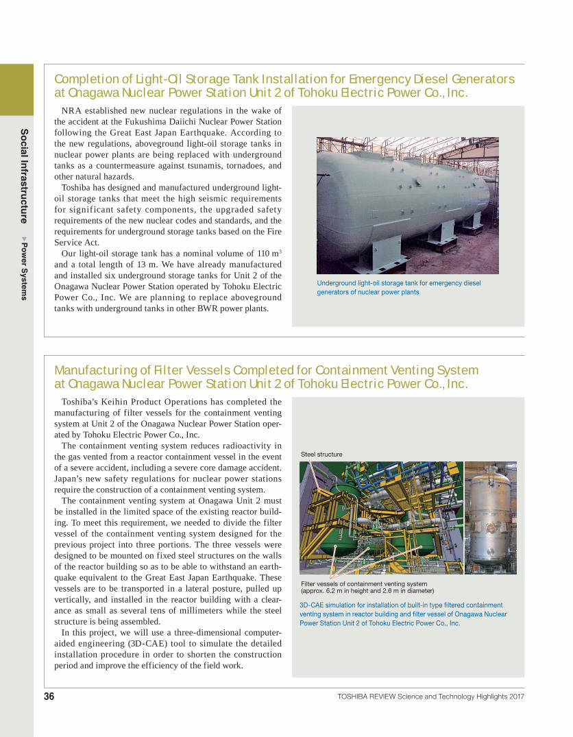
Completion of Light-Oil Storage Tank Installation for Emergency Diesel Generators at Onagawa Nuclear Power Station Unit 2 of Tohoku Electric Power Co., Inc.
NRA established new nuclear regulations in the wake of the accident at the Fukushima Daiichi Nuclear Power Station following the Great East Japan Earthquake. According to the new regulations, aboveground light-oil storage tanks in nuclear power plants are being replaced with underground tanks as a countermeasure against tsunamis, tornadoes, and other natural hazards.
Toshiba has designed and manufactured underground light-oil storage tanks that meet the high seismic requirements for signif icant safety components, the upgraded safety requirements of the new nuclear codes and standards, and the requirements for underground storage tanks based on the Fire Service Act.
Our light-oil storage tank has a nominal volume of 110 m3 and a total length of 13 m. We have already manufactured and installed six underground storage tanks for Unit 2 of the Onagawa Nuclear Power Station operated by Tohoku Electric Power Co., Inc. We are planning to replace aboveground tanks with underground tanks in other BWR power plants.
Underground light-oil storage tank for emergency diesel generators of nuclear power plants
Manufacturing of Filter Vessels Completed for Containment Venting System at Onagawa Nuclear Power Station Unit 2 of Tohoku Electric Power Co., Inc.
Toshiba’s Keihin Product Operations has completed the manufacturing of filter vessels for the containment venting system at Unit 2 of the Onagawa Nuclear Power Station oper-ated by Tohoku Electric Power Co., Inc.
The containment venting system reduces radioactivity in the gas vented from a reactor containment vessel in the event of a severe accident, including a severe core damage accident. Japan’s new safety regulations for nuclear power stations require the construction of a containment venting system.
The containment venting system at Onagawa Unit 2 must be installed in the limited space of the existing reactor build-ing. To meet this requirement, we needed to divide the filter vessel of the containment venting system designed for the previous project into three portions. The three vessels were designed to be mounted on fixed steel structures on the walls of the reactor building so as to be able to withstand an earth-quake equivalent to the Great East Japan Earthquake. These vessels are to be transported in a lateral posture, pulled up vertically, and installed in the reactor building with a clear-ance as small as several tens of millimeters while the steel structure is being assembled.
In this project, we will use a three-dimensional computer-aided engineering (3D-CAE) tool to simulate the detailed installation procedure in order to shorten the construction period and improve the efficiency of the field work.
Filter vessels of containment venting system (approx. 6.2 m in height and 2.6 m in diameter)
Steel structure
3D-CAE simulation for installation of built-in type filtered containment venting system in reactor building and filter vessel of Onagawa Nuclear Power Station Unit 2 of Tohoku Electric Power Co., Inc.

37
Social Infrastructure Power System
s
TOSHIBA REVIEW Science and Technology Highlights 2017
Energization of Sur and Jahloot 400 kV Substations in OmanOman Electricity Transmission Company (OETC) is
planning to expand its 400 kV electric power grid to meet increasing electricity demand. Toshiba Transmission & Distribution Systems Gulf S.P.C. (TTDG) has constructed the first 400 kV substation in the Sultanate of Oman(*), the first full-turnkey (FTK) project for the Toshiba Group in that country.
Under the contract, TTDG constructed two substations. Toshiba supplied 400 kV gas-insulated switchgears (GIS) as well as 750 MVA and 500 MVA transformers to the substations, which were successfully energized in July 2016. This project succeeded due to the experience and high-level capabilities of our team, and marked a major milestone for Toshiba in the Middle East market.
(*) As of April 2016 (as researched by Toshiba)
Shipment of 333.3 MVA Transformers for Bangkok Noi and Chaeng Wattana Substations in Thailand
Toshiba shipped eight 333.3 MVA transformers to the Electricity Generation Authority of Thailand (EGAT) for the Bangkok Noi and Chaeng Wattana Substations located in the central area of Bangkok, Thailand, in May 2016. We were awarded a contract for the manufacture of eight of the 24 transformers required by these facilities, together with Changzhou Toshiba Transformer Co., Ltd.
Due to the rapid growth in population and electric-ity demand in central Bangkok, key considerations for substations there include compact size and environmental friendliness. Therefore, the customer’s requirements included low power loss and the need to satisfy transpor-tation restrictions. Our transformers were designed and manufactured to meet these requirements.
The Bangkok Noi and Chaeng Wattana Substations were energized in August 2017.
333.3 MVA-525 kV transformer for Chaeng Wattana Substation, Thailand
400 kV GIS for Jahloot Grid Station, Oman
500 MVA transformer for Jahloot Grid Station

Social Infrastructure Power System
s
38 TOSHIBA REVIEW Science and Technology Highlights 2017
Completion of Factory Tests of Suspended Thyristor Valve for DC Power Transmission System Connecting Italy and Montenegro
Toshiba has developed a suspended thyristor valve for high-voltage DC (HVDC) power transmission equipment (±500 kV-1 200 MW) connecting Italy and Montenegro. We were awarded a contract for this thyristor valve by Terna Rete Italia S.p.A.
This was Toshiba’s first attempt to develop a suspended thyris-tor valve, with the aim of entering the overseas HVDC market.
While the conventional free-standing thyristor valve is struc-turally supported by rigid insulators, the new thyristor valve is suspended by suspension insulators.
We completed all factory tests in Japan, comprising type tests (including insulation and operation tests) of the valve modules and a quadruple thyristor valve in March 2016, and acceptance tests of the valve modules for both Italy and Montenegro based on the International Electrotechnical Commission (IEC) 60700-1 standard in July 2016. We also performed a customer witness test of the quadruple thyristor valve at our Hamakawasaki Operations facility in January 2016 and obtained the approval of Terna.
We began shipment of the thyristor valve at the end of 2016, in order to commence on-site installation and testing in 2017.
Completion of Factory Acceptance Tests on All 230 MVA-400/ 3 kV Converter Transformers for HVDC Transmission System between Italy and Montenegro
Toshiba has developed a converter transformer for an HVDC power transmission system (±500 kV-1 200 MW) running between Italy and Montenegro. We were awarded a contract for this converter transformer by Terna Rete Italia S.p.A.
This transformer is a single-phase type and has three windings consisting of one line winding and two valve windings (with star and delta connections). The valve windings were designed taking the combined load stress of the AC and DC voltages into consideration.
We successfully performed the type test in accordance with the relevant IEC standard as well as special tests including a short-circuit test and a long-term polarity reversal test (including partial discharge measurement).
In addition, we performed various factory acceptance tests to verify 25 characteristics. Among these were a DC separate source-voltage withstand test (including partial discharge measurement) and a polarity reversal test (also including partial discharge measurement). All of the tests were successfully com-pleted on all 14 transformer units in October 2016.
The erection work in Italy commenced in February 2017. The erection work in Montenegro will start when its site becomes ready in 2017.
Converter transformer for HVDC power transmission system between Italy and Montenegro undergoing factory acceptance test and its rated specifications
Item Rating
Rated power 230 MVANumber of phases 1Connection symbol (after 3 phases connected) YNy0d1
Rated voltageLine winding 400/ 3 kV, +11.25/-6.75%Valve winding (Y) 205/ 3 kVValve winding (D) 205 kV
Frequency 50 HzType of cooling ODAFApplied standard IEC 61378-2
ODAF: oil-directed air-forced cooling
Suspended thyristor valve for DC power transmission system connecting Italy and Montenegro and its rated specifications
Item Specification
Nominal power 500 MW × dipolesDC nominal voltage ±500 kVNominal current 1 000 A (overload condition: 1 200 A)Converter type 12-pulse converter
Valve structure Quadruple thyristor valve (MVU: multi-valve unit structure), suspended type

39
Social Infrastructure Power System
s
TOSHIBA REVIEW Science and Technology Highlights 2017
TEPCO Power Grid Dynamic Rating System to Increase Available Transformer Capacity
With the expanding connection of renewable ener-gy sources to existing power grids, transformers and other power transmission devices are often required to briefly operate beyond their rated capacities. This is possible because the capacity of a transformer is rated with some margin to make it operable under high ambient temperature and other severe condi-tions.
Under these circumstances, Toshiba has developed a dynamic rating system to increase the available capacity of a transformer. This system calculates a possible operating capacity for actual operation based on the ambient temperature, oil temperature, and electric current, and informs the system opera-tors of its result. The dynamic rating system allows operators to eff iciently use existing equipment without degrading the power system reliability or upgrading a transformer at high cost.
We have installed the dynamic rating system for a 500/275 kV transformer at the Boso Substation of TEPCO Power Grid, Inc.
500 kV busbar
500/275 kV transformer
Ambient temperature sensor
Ambient temperature Ambient
and oil temperaturesOil
temperature
275 kV busbar
Sensor data aggregator
Dynamic transformer rating system
Information for operation support
Control signals
Trip signal
Networkfor control
Control
Load
Generators
Renewableenergy
PC for operators
Voltage transformer for measurement
Voltage
Current
Current transformer for measurement
Configuration of dynamic rating system to increase available transformer capacity
Energy Management System for Central Load Dispatching Center of The Chugoku Electric Power Co., Inc.
The energy management system installed at the central load dispatching center of The Chugoku Electric Power Co., Inc. has been operating without problems since it came online in January 2016.
In April 2016, in response to the second phase of the electricity system reform being implemented in Japan, Toshiba added new functions to the energy management system such as linkage to the system operated by the Organization for Cross-regional Coordination of Transmission Operators, Japan (OCCTO).
The energy management system plays a key role in power grid operation. In order to ensure stable supplies of high-quality electricity, economical operation balancing demand and supply, and prompt response in the event of an emergency, we focused on improving the following major functions:• load frequency control for the provision of high-
quality electricity• power generation scheduling and economic load
dispatching control to achieve economical power generation
• human interfaces based on the analysis of past incidents of operator error.
Central load dispatching center of The Chugoku Electric Power Co., Inc.

Social Infrastructure Power System
s
40 TOSHIBA REVIEW Science and Technology Highlights 2017
Smart Meter Communication System for TEPCO Power Grid, Inc.In July 2015, TEPCO Power Grid, Inc. commenced operation
of a smart metering infrastructure comprising smart meters, a communication system, an operational management system, and other systems throughout its service area. Toshiba served as a system integrator for the development of the communication system, which consists of communication units integrated in smart meters, data concentrators, a head-end system, and so on. A total of 27 million smart meters will be installed by fiscal year 2020. Upon completion, it is expected to be the world’s largest smart metering infrastructure.
We improved communication quality using new technologies. For example, our communication system incorporates a tech-nology to automatically re-collect electricity data from smart meters, achieving a data collection rate exceeding 99.9% for a meter infrastructure with more than 10 million smart meters.
We will continue to expand the head-end system so as to accommodate 27 million smart meters. Our smart meter com-munication system is making a contribution to the stabilization of operation as a central information infrastructure in response to further liberalization of Japan’s electricity market.
In addition, we are planning to develop a new service using the collected big data as well as the network of this smart meter communication system.
System of electricity retailer
PLC
Developed by Toshiba
Head-end system
HEMSHEMS HEMS
HEMS: home energy management systemPLC: power line communication3G: 3rd generationLTE: Long Term Evolution
Wide area network
The head-end system is being expanded to accommodate 27 million meters.
Contribution to stabilization of operation in response to electricity liberalization
Meter data management system
Cellular communication (3G/LTE)
99.9% meter data collection rate using improved technology to automatically re-collect electricity data and other technologies
Wireless multihop communication
Consignation system
Overview of smart meter system being promoted by TEPCO Power Grid, Inc.
Latest Power Supply and Demand Management System to Support Planned Power Balancing
Since the full liberalization of the Japanese retail electricity market, including the low-voltage consumer segment, there has been a growing need for systems for power producers and sup-pliers (PPS) that support planned power balancing and perform demand forecasting for the increasing number of new low-voltage consumers. To meet this need, Toshiba has developed a power supply and demand management system for PPS opera-tors based on its know-how cultivated through the development of electricity supply and demand control technologies.
This system provides an accurate forecasting function based on the results of the latest research and an optimal planning and scheduling function. These functions contribute to maximiza-tion of the operators’ revenue. In addition, this system has a function for automatic night and holiday operation, which helps to reduce the workloads of operators. We can provide a set of specific functions according to the operational needs of indi-vidual PPS operators, such as forecasting of photovoltaic (PV) power generation, demand response, and exchange of power generation information.
Forecasting
Records Planning andscheduling
Updating ofschedule
Monitoring of supply-demand balancing
Weatherforecastingcompany
Powergenerationcompany
Powercompany
OCCTO
JEPX
JEPX: Japan Electric Power Exchange
Overview of power supply and demand management system for power producers and suppliers
List of functions
ForecastingDemand forecasting function for low-voltage and high-voltage consumersPrice forecasting functionPV power generation forecasting function
Planning and scheduling
Creation of optimal plan and schedule to maximize revenue
Monitoring of supply-demand balancing Monitoring of supply-demand balancing with alerts
Updating of schedule Manual and automatic updating of schedule when supply-demand imbalance occurs
Records Export of system database in comma-separated values (CSV) format

41
Social Infrastructure Power System
s
TOSHIBA REVIEW Science and Technology Highlights 2017
Demand Forecasting Technology for Supply and Demand Systems of Power Producers and Suppliers
Japan fully liberalized its electricity market in April 2016, making it necessary for PPS to manage the supply and demand of low-voltage consumers (e.g., households) in addition to high-voltage consumers (e.g., buildings and factories). In response, Toshiba has developed a new technology for forecasting the electricity demand of low-voltage consumers since the demand of such consumers is less regular than that of high-voltage consumers.
This technology statistically forecasts consumers’ demand for the next day based on the past demand and weather records. Drawing on our experience with services and demonstration projects for low-voltage consumers, we have generated regression models for each time slot(*) of each day of the week in order to address irregularities in demand. Furthermore, PPS operators can create consumer groups to improve the accuracy of forecasts and reduce calculation time.
We have delivered supply and demand systems incorpo-rating this technology to several PPS operators, and will continue our efforts to further improve the accuracy and usability of forecasts.
(*) One day consists of 48 time slots of 30 minutes each. Electricity supply and demand is managed on a time slot basis.
Elec
tricit
y dem
and
Sat. Wed. Fri.
electricity demand
Calculation flow of demand forecasting for low-voltage consumers and example of demand forecasting result
Completion of Demonstration Experiment for High-Accuracy Demand Response
In the FY2016 Advanced Demand Response Demonstration Project sponsored by METI, Toshiba conducted a demonstra-tion experiment for high-accuracy demand response (DR).
The purpose of the experiment was to find ways for an aggregator to select customers to whom DR requests would be dispatched according to weather forecasts, predicted tem-peratures, power usage, and other conditions in order to meet a targeted reduction in the amount of electricity consumed.
The results of the experiment showed a 4 055 kW reduction in electricity demand as against the contracted amount of 4 000 kW. This was the highest accuracy ever achieved, with an error of only 1.4%.
In order to provide stable negawatt power (*) for power utilities, we will continue to improve the accuracy of nega-watt/DR prediction and increase the number of customers in DR programs as part of our efforts to achieve the practical realization of negawatt trading.
(*) Energy regarded as surplus by the supplier side as a result of customers’ efforts to save, create, and store energy
Power utility DR request
Sale of negawatt power
AggregatorDR request Customers
Aggregation of negawatt power
Overview of DR demonstration

Social Infrastructure Power System
s
42 TOSHIBA REVIEW Science and Technology Highlights 2017
Completion of Mega Solar Power Plant in Okayama, JapanToshiba has completed the construction of the Shin-
Okayama Solar Power Plant, a mega solar power plant in Okayama, Japan. We received an engineering, procurement, and construction (EPC) contract for the plant from a special-purpose company (SPC) established for the project.
The Shin-Okayama Solar Power Plant has a DC output of 37 MW and began commercial operation in January 2017.
The main features of this solar power plant include the fol-lowing:• The support structures for the PV panels are installed
along the complex sloping topography of a former golf course located on a hillside.
• Toshiba’s high-performance monocrystal 260 W module is utilized.
• The plant is equipped with a GIS for 110 kV grid connec-tion.
We have also received a 20-year contract for the operation and maintenance (O&M) of the solar power plant from the SPC. As a consequence, we have been providing comprehen-sive services for this project from plant construction through to O&M.
Through this experience, we are accumulating know-how necessary for the solar power generation business and intend to utilize this know-how to contribute to the successful growth of the renewable energy sector.
Shin-Okayama Solar Power Plant
Commencement of Operation of H2OneTM Resort Model Installed at Henn na Hotel Huis Ten Bosch
H2OneTM is a hydrogen-based autonomous energy supply system free of CO2 emissions. This system utilizes renewable energy to produce hydrogen, which is then used as a fuel to generate electricity when required. Its resort model installed at the Henn na Hotel Huis Ten Bosch in Nagasaki Prefecture started operation in March 2016.
The model at the Henn na Hotel Huis Ten Bosch is a fully independent power supply facility and can supply electricity to 12 rooms in the hotel regardless of the weather conditions. Since H2OneTM can store hydrogen for a long period of time, it also serves as a power storage system. Moreover, its hydrogen energy management system provides optimal system manage-ment throughout the year. In particular, since the H2OneTM model installed at the Henn na Hotel Huis Ten Bosch has a hydrogen storage alloy tank that can store 10 times as much hydrogen as a conventional tank under the same pressure, a large amount of hydrogen can be stored in a small space.
Toshiba is planning to further optimize and scale up the system configuration of H2OneTM in order to expand sales and promote local self-sufficiency in electricity.
H2OneTM hydrogen-based autonomous energy supply system installed in West Arm of Henn na Hotel Huis Ten Bosch


![Commencement of Commercial Production [Company Update]](https://static.fdocuments.net/doc/165x107/577cb2221a28aba7118bed52/commencement-of-commercial-production-company-update.jpg)


