
COMFORTLINK™ Controls Installation Instructions · Manufacturer reserves the right to...
36
Manufacturer reserves the right to discontinue, or change at any time, specifications or designs without notice and without incurring obligations. Catalog No. 04-53480067-01 Printed in U.S.A. Form 48A-7SI Pg 1 8-09 Replaces: 48A-5SI Installation Instructions CONTENTS Page SAFETY CONSIDERATIONS . . . . . . . . . . . . . . . . . . . . . . 1 INSTALLATION . . . . . . . . . . . . . . . . . . . . . . . . . . . . . . . . 1-36 Step 1 — Provide Unit Support . . . . . . . . . . . . . . . . . . . 1 • ROOF CURB • ALTERNATE UNIT SUPPORT Step 2 — Rig and Place Unit . . . . . . . . . . . . . . . . . . . . . 2 • POSITIONING • ROOF MOUNT Step 3 — Field Fabricate Ductwork . . . . . . . . . . . . . . . 2 Step 4 — Make Unit Duct Connections . . . . . . . . . . . 2 Step 5 — Install Flue Hood . . . . . . . . . . . . . . . . . . . . . . 19 Step 6 — Trap Condensate Drain . . . . . . . . . . . . . . . . 19 Step 7 — Install Gas Piping . . . . . . . . . . . . . . . . . . . . . 19 Step 8 — Make Electrical Connections . . . . . . . . . . 20 • POWER WIRING • FIELD POWER SUPPLY • FIELD CONTROL WIRING Step 9 — Make Outdoor-Air Inlet Adjustments . . . . . . . . . . . . . . . . . . . . . . . . . . . . . . . . . . 32 • ECONOMIZER AND FIXED OUTDOOR AIR DAMPER Step 10 — Position Power Exhaust/Barometric Relief Damper Hood. . . . . . . . . . . . . . . . . . . . . . . . . . . 33 Step 11 — Route VAV Static Pressure Sensor . . . 34 Step 12 — Install All Accessories . . . . . . . . . . . . . . . 35 Step 13 — Field Modifications . . . . . . . . . . . . . . . . . . . 35 SAFETY CONSIDERATIONS Installation and servicing of air-conditioning equipment can be hazardous due to system pressure and electrical compo- nents. Only trained and qualified service personnel should in- stall, repair, or service air-conditioning equipment. Untrained personnel can perform the basic maintenance functions of cleaning coils and filters and replacing filters. All other operations should be performed by trained service per- sonnel. When working on air-conditioning equipment, observe precautions in the literature, tags and labels attached to the unit, and other safety precautions that may apply. Follow all safety codes. Wear safety glasses and work gloves. Use quenching cloth for unbrazing operations. Have fire extinguishers available for all brazing operations. INSTALLATION Step 1 — Provide Unit Support WARNING Before performing service or maintenance operations on unit, turn off main power switch to unit. Electrical shock could cause personal injury. WARNING 1. Improper installation, adjustment, alteration, service, or maintenance can cause property damage, personal injury, or loss of life. Refer to the User’s Information Manual provided with this unit for more details. 2. Do not store or use gasoline or other flammable va- pors and liquids in the vicinity of this or any other appliance. What to do if you smell gas: 1. DO NOT try to light any appliance. 2. DO NOT touch any electrical switch, or use any phone in your building. 3. IMMEDIATELY call your gas supplier from a neigh- bor’s phone. Follow the gas supplier’s instructions. 4. If you cannot reach your gas supplier, call the fire department. WARNING Disconnect gas piping from unit when pressure testing at pressure greater than 0.5 psig. Pressures greater than 0.5 psig will cause gas valve damage resulting in hazardous condition. If gas valve is subjected to pressure greater than 0.5 psig, it must be replaced before use. When pressure testing field-supplied gas piping at pressures of 0.5 psig or less, a unit connected to such piping must be isolated by closing the manual gas valve(s). CAUTION 1. All panels must be in place when rigging or damage to unit may occur. 2. Unit is not designed for handling by fork truck. WEATHERMAKER ® 48AJ,AK,AW,AY020-060 Single Package Rooftop Units Electric Cooling/Gas Heating with Scroll Compressor and COMFORTLINK™ Controls
Transcript of COMFORTLINK™ Controls Installation Instructions · Manufacturer reserves the right to...
Manufacturer reserves the right to discontinue, or change at any time, specifications or designs without notice and without incurring obligations.Catalog No. 04-53480067-01 Printed in U.S.A. Form 48A-7SI Pg 1 8-09 Replaces: 48A-5SI
Installation InstructionsCONTENTS
PageSAFETY CONSIDERATIONS . . . . . . . . . . . . . . . . . . . . . . 1INSTALLATION . . . . . . . . . . . . . . . . . . . . . . . . . . . . . . . . 1-36Step 1 — Provide Unit Support . . . . . . . . . . . . . . . . . . . 1• ROOF CURB• ALTERNATE UNIT SUPPORTStep 2 — Rig and Place Unit . . . . . . . . . . . . . . . . . . . . . 2• POSITIONING• ROOF MOUNTStep 3 — Field Fabricate Ductwork . . . . . . . . . . . . . . . 2Step 4 — Make Unit Duct Connections . . . . . . . . . . . 2Step 5 — Install Flue Hood . . . . . . . . . . . . . . . . . . . . . . 19Step 6 — Trap Condensate Drain . . . . . . . . . . . . . . . . 19Step 7 — Install Gas Piping . . . . . . . . . . . . . . . . . . . . . 19Step 8 — Make Electrical Connections . . . . . . . . . . 20• POWER WIRING• FIELD POWER SUPPLY• FIELD CONTROL WIRINGStep 9 — Make Outdoor-Air Inlet
Adjustments . . . . . . . . . . . . . . . . . . . . . . . . . . . . . . . . . . 32• ECONOMIZER AND FIXED OUTDOOR
AIR DAMPERStep 10 — Position Power Exhaust/Barometric
Relief Damper Hood. . . . . . . . . . . . . . . . . . . . . . . . . . . 33Step 11 — Route VAV Static Pressure Sensor . . . 34Step 12 — Install All Accessories . . . . . . . . . . . . . . . 35Step 13 — Field Modifications. . . . . . . . . . . . . . . . . . . 35
SAFETY CONSIDERATIONSInstallation and servicing of air-conditioning equipment can
be hazardous due to system pressure and electrical compo-nents. Only trained and qualified service personnel should in-stall, repair, or service air-conditioning equipment.
Untrained personnel can perform the basic maintenancefunctions of cleaning coils and filters and replacing filters. Allother operations should be performed by trained service per-sonnel. When working on air-conditioning equipment, observeprecautions in the literature, tags and labels attached to the unit,and other safety precautions that may apply.
Follow all safety codes. Wear safety glasses and workgloves. Use quenching cloth for unbrazing operations. Havefire extinguishers available for all brazing operations.
INSTALLATION
Step 1 — Provide Unit Support
WARNING
Before performing service or maintenance operations onunit, turn off main power switch to unit. Electrical shockcould cause personal injury.
WARNING
1. Improper installation, adjustment, alteration, service,or maintenance can cause property damage, personalinjury, or loss of life. Refer to the User’s InformationManual provided with this unit for more details.
2. Do not store or use gasoline or other flammable va-pors and liquids in the vicinity of this or any otherappliance.
What to do if you smell gas:1. DO NOT try to light any appliance.2. DO NOT touch any electrical switch, or use any
phone in your building.3. IMMEDIATELY call your gas supplier from a neigh-
bor’s phone. Follow the gas supplier’s instructions.4. If you cannot reach your gas supplier, call the fire
department.
WARNING
Disconnect gas piping from unit when pressure testing atpressure greater than 0.5 psig. Pressures greater than0.5 psig will cause gas valve damage resulting in hazardouscondition. If gas valve is subjected to pressure greater than0.5 psig, it must be replaced before use. When pressuretesting field-supplied gas piping at pressures of 0.5 psig orless, a unit connected to such piping must be isolated byclosing the manual gas valve(s).
CAUTION
1. All panels must be in place when rigging or damageto unit may occur.
2. Unit is not designed for handling by fork truck.
WEATHERMAKER®
48AJ,AK,AW,AY020-060Single Package Rooftop UnitsElectric Cooling/Gas Heatingwith Scroll Compressor and COMFORTLINK™ Controls
2
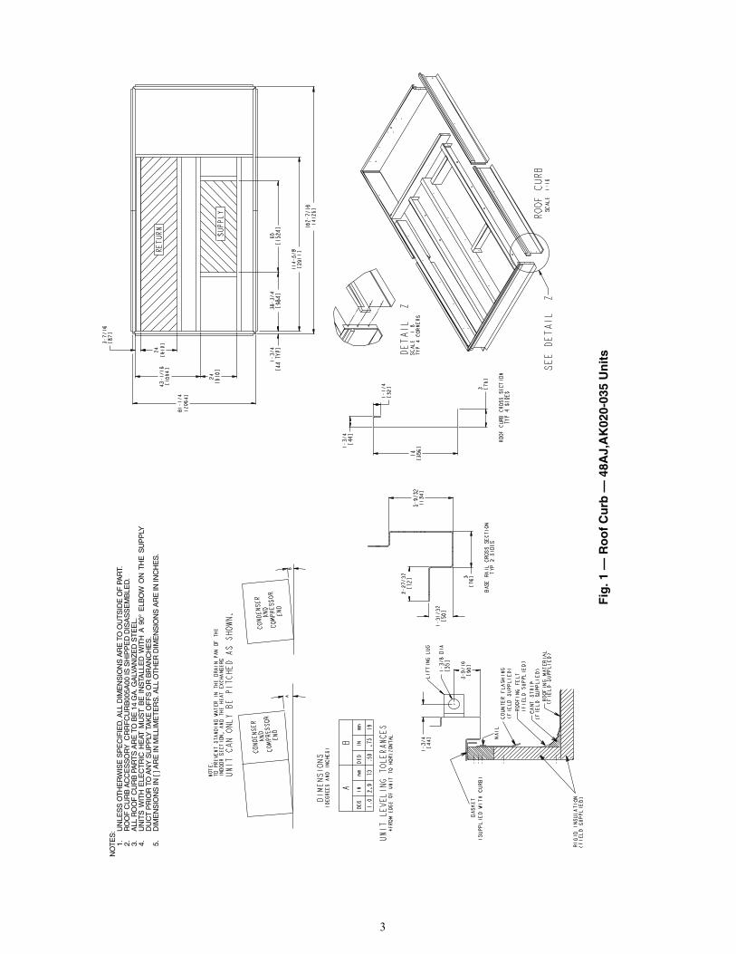
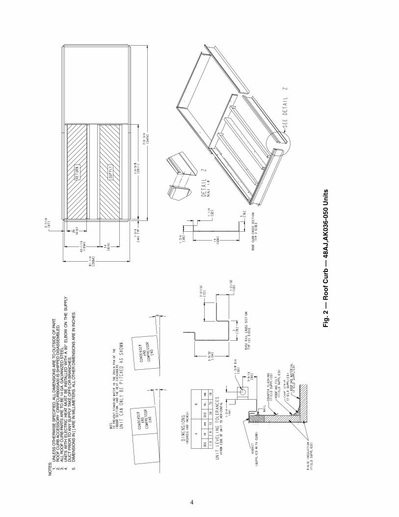
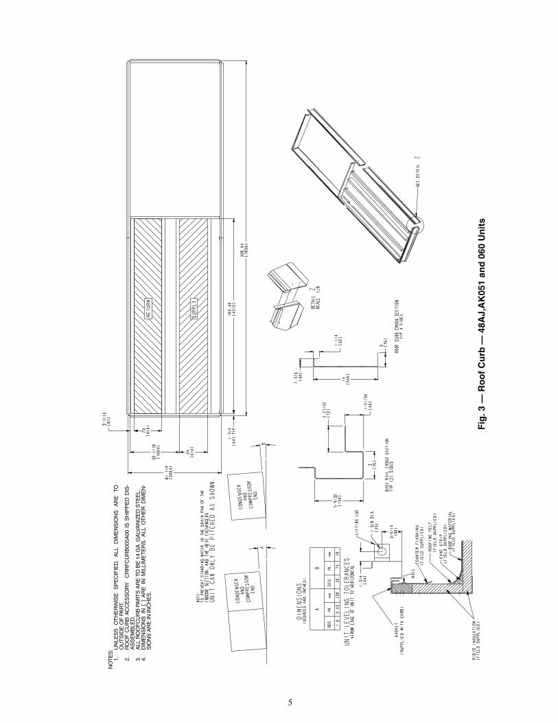
ROOF CURB — For vertical discharge units, assemble or in-stall accessory roof curb in accordance with instructionsshipped with this accessory. See Fig. 1-3. Install insulation,cant strips, roofing, and counter flashing as shown. Ductworkcan be installed to roof curb before unit is set in place. Curbshould be level. This is necessary to permit unit drain to func-tion properly. Unit leveling tolerance is shown in Fig. 1-3.Refer to Accessory Roof Curb Installation Instructions foradditional information as required. When accessory roof curbis used, unit may be installed on class A, B, or C roof coveringmaterial.
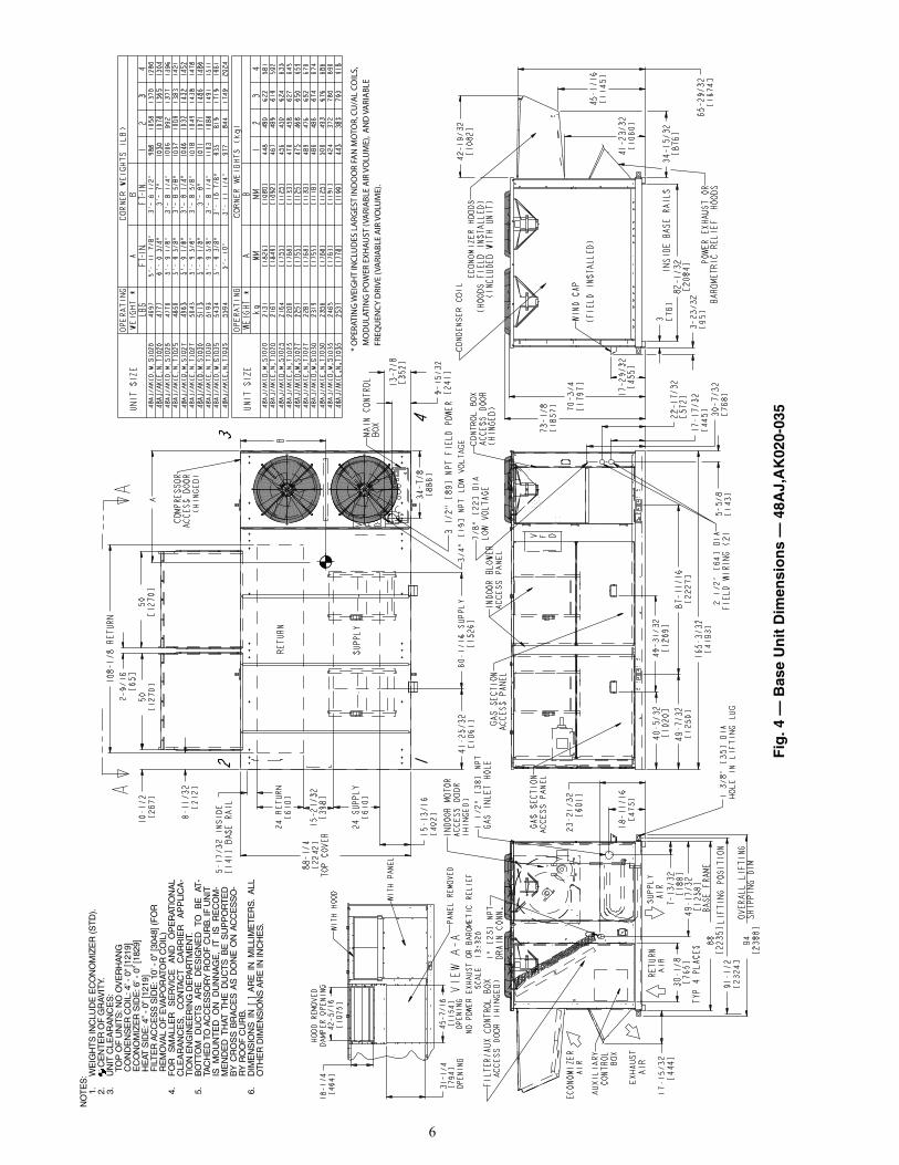
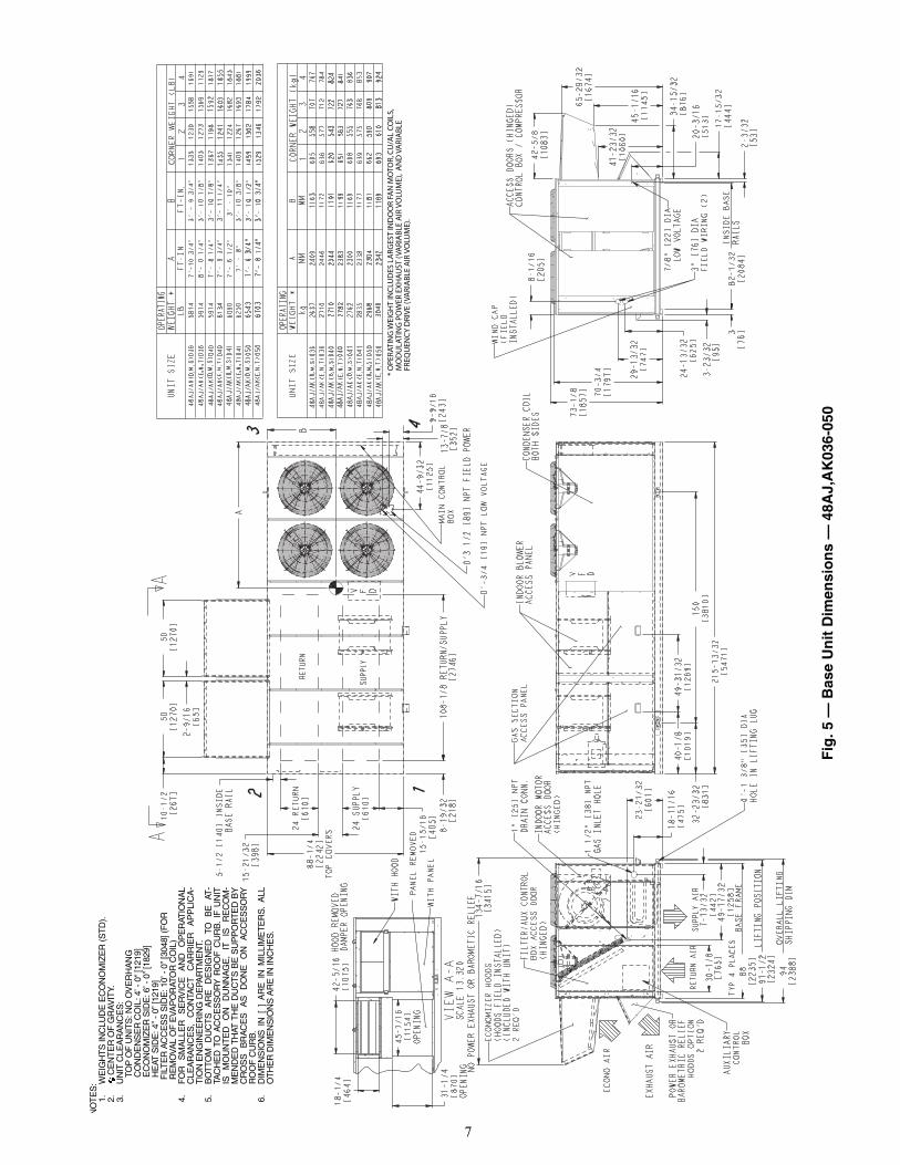
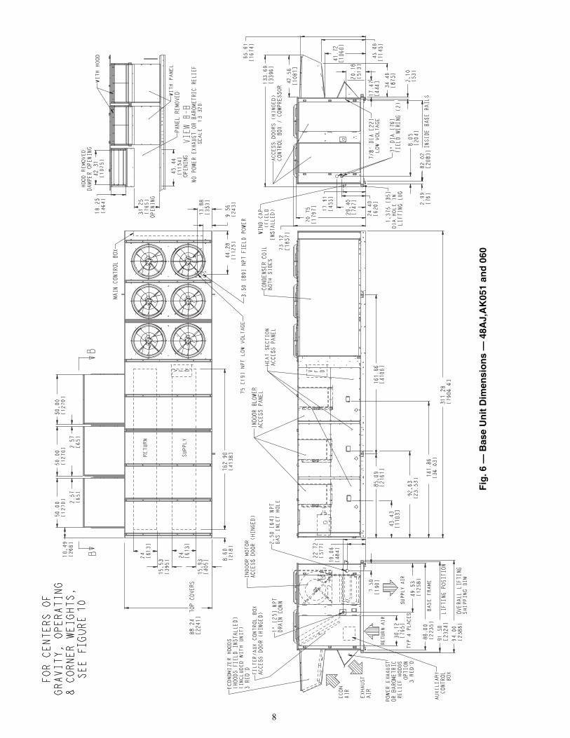
ALTERNATE UNIT SUPPORT — When the preferred curbor slab mount cannot be used, support unit with sleepers on pe-rimeter, using unit curb support area. If sleepers cannot beused, support long sides of unit (refer to Fig. 4-10) with a mini-mum number of 4-in. x 4-in. pads spaced as follows:48AJ,AK,AW,AY020-035 units require 3 pads on each side;48AJ,AK,AW,AY036-050 units require 4 pads on each side;48AJ,AK,AW,AY051 and 060 units require 6 pads on eachside. Unit may sag if supported by corners only.
Step 2 — Rig and Place Unit — Inspect unit fortransportation damage. See Tables 1-6 for physical data andspecifications. File any claim with transportation agency.
Do not drop unit; keep upright. Use spreader bars over unitto prevent sling or cable damage. This unit must be handledwith a crane and can not be handled by a fork truck. Level byusing unit frame as a reference; leveling tolerance is shown inFig. 1-3. See Fig. 10 for additional information. Unit operatingweight is shown in Table 2.NOTE: On retrofit jobs, ductwork may be attached to the oldunit instead of a roof curb. Be careful not to damage ductworkwhen removing old unit. Attach existing ductwork to roof curbinstead of unit.
Four lifting lugs are provided on the unit base rails as shownin Fig. 4-10. Refer to rigging instructions on unit.POSITIONING — Maintain clearance, per Fig. 4-10, aroundand above unit to provide minimum distance from combustiblematerials, proper airflow, and service access.
Do not install unit in an indoor location. Do not locate unitair inlets near exhaust vents or other sources of contaminatedair. For proper unit operation, adequate combustion and venti-lation air must be provided in accordance with Section 5.3 (Airfor Combustion and Ventilation) of the National Fuel GasCode, ANSI Z223.1 (American National Standards Institute).
Although unit is weatherproof, guard against water fromhigher level runoff and overhangs.
Locate mechanical draft system flue assembly at least 4 ftfrom any opening through which combustion products couldenter the building, and at least 4 ft from any adjacent building.When unit is located adjacent to public walkways, flue assem-bly must be at least 7 ft above grade.ROOF MOUNT — Check building codes for weight distribu-tion requirements. See Fig. 11. Unit operating weight is shownin Table 2.
Step 3 — Field Fabricate Ductwork — Secure allducts to building structure. Use flexible duct connectors be-tween unit and ducts as required. Insulate and weatherproof allexternal ductwork, joints, and roof openings with counterflashing and mastic in accordance with applicable codes.NOTE: Due to width of the horizontal supply and return duct-work, provisions should be made for servicing of the outdoorair filters (i.e., catwalk over ductwork).
Ducts passing through an unconditioned space must be in-sulated and covered with a vapor barrier. Outlet grilles must notlie directly below unit discharge. The return duct must have a90-degree elbow before opening into the building space if theunit is equipped with power exhaust.
To attach ductwork to roof curb, insert duct approximately10 to 11 in. up into roof curb. Connect ductwork to 14-gageroof curb material with sheet metal screws driven from insidethe duct.
Follow AMCA (Air Movement and Control Association)guidelines relating to ductwork connections to the unit. Theseguidelines recommend a minimum 21/2 equivalent duct diame-ters of straight duct connected to supply air inlet and outletopenings before any transitions, fittings, dampers, etc. Failureto adhere to these guidelines may result in system effects whichcan impact the unit’s ability to achieve published performance.
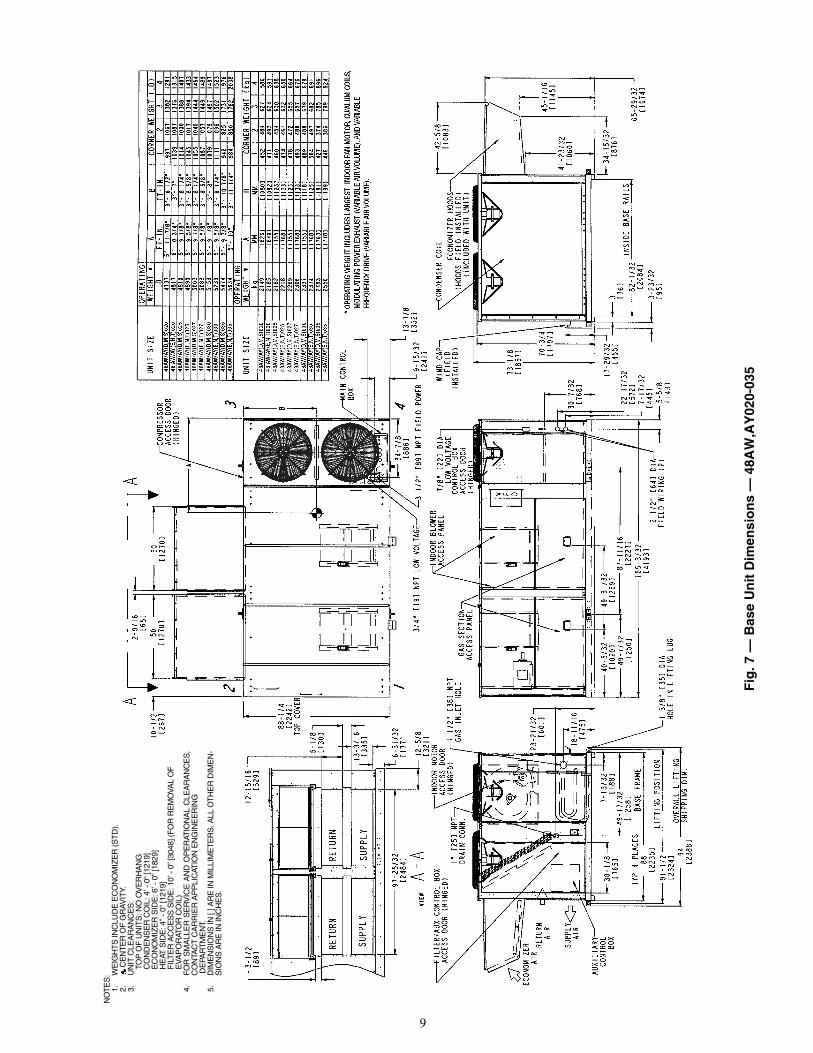
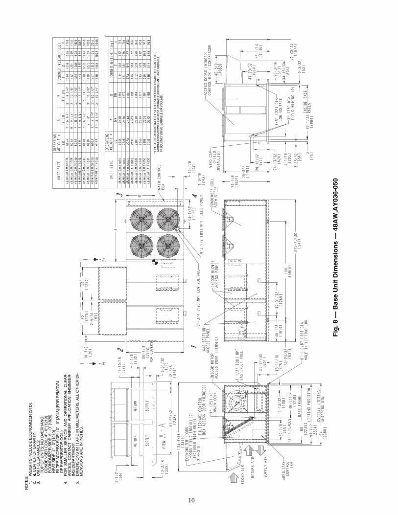
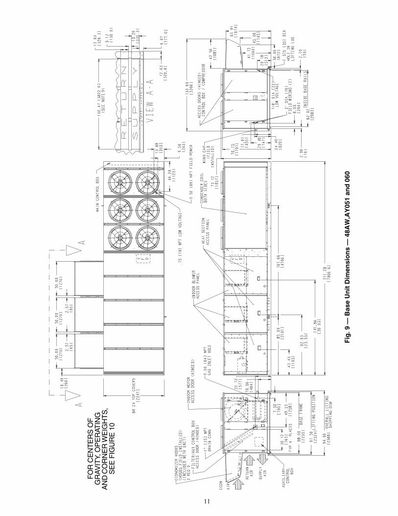
Step 4 — Make Unit Duct Connections48AJ AND AK UNITS — Unit is shipped for thru-the-bottom duct connections. Field-fabricated ductwork should beattached to the roof curb. Supply and return duct dimensionsare shown in Fig. 4-6. Air distribution is shown in Fig. 12.Refer to installation instructions shipped with roof curb formore information.48AW AND AY UNITS — Remove shipping covers fromsupply and return air openings. Attach field-supplied ductworkto unit. Connect to the unit with a single duct for all supplyopenings and with a single duct for all return openings.Splitting of the airflow into branch ducts should not be done atthe unit. Sufficient duct length should be used prior to branch-ing to ensure the air temperatures are well mixed within theductwork. See Fig. 7-9 for duct opening dimensions. Secure allducts to building structure. Air distribution is shown in Fig. 7-9and Fig. 13.
Install accessory barometric relief or power exhaust in thefield-fabricated return ductwork. Refer to Step 10 — PositionPower Exhaust/Barometric Relief Damper Hood section onpage 33 for more information.
Instructions continued on page 19.
IMPORTANT: The gasketing of the unit to the roof curb iscritical for a watertight seal. Install gasket with the roofcurb as shown in Fig. 1-3. Improperly applied gasket canalso result in air leaks and poor unit performance.
WARNING
For vertical supply and return units, tools or parts coulddrop into ductwork and cause an injury. Install a 90-degreeelbow turn in the supply and return ductwork between theunit and the conditioned space. If a 90-degree elbow cannotbe installed, then a grille of sufficient strength and densityshould be installed to prevent objects from falling into theconditioned space.
3
Fig
. 1 —
Ro
of
Cu
rb —
48A
J,A
K02
0-03
5 U
nit
s
a48-6715NO
TE
S:
1.U
NLE
SS
OT
HE
RW
ISE
SP
EC
IFIE
D, A
LL D
IME
NS
ION
S A
RE
TO
OU
TS
IDE
OF
PA
RT.
2.R
OO
F C
UR
B A
CC
ES
SO
RY
CR
RF
CU
RB
005A
00 IS
SH
IPP
ED
DIS
AS
SE
MB
LED
.3.
ALL
RO
OF
CU
RB
PA
RT
S A
RE
TO
BE
14
GA
. GA
LVA
NIZ
ED
ST
EE
L.4.
UN
ITS
WIT
H E
LEC
TR
IC H
EAT
MU
ST
BE
IN
STA
LLE
D W
ITH
A 9
0° E
LBO
W O
N T
HE
SU
PP
LYD
UC
T P
RIO
R T
O A
NY
SU
PP
LY T
AK
E O
FF
S O
R B
RA
NC
HE
S.
5.D
IME
NS
ION
S IN
[ ] A
RE
IN M
ILLI
ME
TE
RS
. ALL
OT
HE
R D
IME
NS
ION
S A
RE
IN IN
CH
ES
.
4
Fig
. 2 —
Ro
of
Cu
rb —
48A
J,A
K03
6-05
0 U
nit
s
a48-6716
NO
TE
S:
1.U
NLE
SS
OT
HE
RW
ISE
SP
EC
IFIE
D, A
LL D
IME
NS
ION
S A
RE
TO
OU
TS
IDE
OF
PA
RT.
2.R
OO
F C
UR
B A
CC
ES
SO
RY
CR
RF
CU
RB
005A
00 IS
SH
IPP
ED
DIS
AS
SE
MB
LED
.3.
ALL
RO
OF
CU
RB
PA
RT
S A
RE
TO
BE
14
GA
. GA
LVA
NIZ
ED
ST
EE
L.4.
UN
ITS
WIT
H E
LEC
TR
IC H
EAT
MU
ST
BE
IN
STA
LLE
D W
ITH
A 9
0° E
LBO
W O
N T
HE
SU
PP
LYD
UC
T P
RIO
R T
O A
NY
SU
PP
LY T
AK
E O
FF
S O
R B
RA
NC
HE
S.
5.D
IME
NS
ION
S IN
[ ] A
RE
IN M
ILLI
ME
TE
RS
. ALL
OT
HE
R D
IME
NS
ION
S A
RE
IN IN
CH
ES
.
5
Fig
. 3 —
Ro
of
Cu
rb —
48A
J,A
K05
1 an
d 0
60 U
nit
s
a48-6717
NO
TE
S:
1.U
NLE
SS
O
TH
ER
WIS
E
SP
EC
IFIE
D,
ALL
D
IME
NS
ION
S
AR
E
TOO
UT
SID
E O
F P
AR
T.2.
RO
OF
CU
RB
AC
CE
SS
OR
Y
CR
RF
CU
RB
005A
00 I
S S
HIP
PE
D D
IS-
AS
SE
MB
LED
.3.
ALL
RO
OF
CU
RB
PA
RT
S A
RE
TO
BE
14
GA
. GA
LVA
NIZ
ED
ST
EE
L.4.
DIM
EN
SIO
NS
IN
[ ]
AR
E I
N M
ILLI
ME
TE
RS
. A
LL O
TH
ER
DIM
EN
-S
ION
S A
RE
IN IN
CH
ES
.
6
* O
PERA
TIN
G W
EIG
HT
INC
LUD
ES L
ARG
EST
IND
OO
R FA
N M
OTO
R, C
U/A
L C
OIL
S,
MO
DU
LATI
NG
PO
WER
EX
HA
UST
(VA
RIA
BLE
AIR
VO
LUM
E),
AN
D V
ARI
AB
LE
FREQ
UEN
CY
DRI
VE
(VA
RIA
BLE
AIR
VO
LUM
E).
Fig
. 4 —
Bas
e U
nit
Dim
ensi
on
s —
48A
J,A
K02
0-03
5
a48-8235
NO
TE
S:
1.W
EIG
HT
S IN
CLU
DE
EC
ON
OM
IZE
R (S
TD
).2.
C
EN
TE
R O
F G
RA
VIT
Y.3.
UN
IT C
LEA
RA
NC
ES
: T
OP
OF
UN
ITS
: NO
OV
ER
HA
NG
CO
ND
EN
SE
R C
OIL
: 4’ -
0“ [
1219
] E
CO
NO
MIZ
ER
SID
E: 6
’ - 0
” [18
29]
HE
AT S
IDE
: 4’’
- 0” [
1219
] F
ILT
ER
AC
CE
SS
SID
E: 1
0’ -
0” [3
048]
(FO
R R
EM
OVA
L O
F E
VAP
OR
ATO
R C
OIL
)4.
FO
R
SM
ALL
ER
S
ER
VIC
E
AN
D
OP
ER
ATIO
NA
LC
LEA
RA
NC
ES
, C
ON
TAC
T
CA
RR
IER
A
PP
LIC
A-
TIO
N E
NG
INE
ER
ING
DE
PAR
TM
EN
T.5.
BO
TTO
M
DU
CT
S
AR
E
DE
SIG
NE
D
TO
BE
AT
-TA
CH
ED
TO
AC
CE
SS
OR
Y R
OO
F C
UR
B. I
F U
NIT
IS M
OU
NT
ED
ON
D
UN
NA
GE
, IT
IS
RE
CO
M-
ME
ND
ED
TH
AT T
HE
DU
CT
S B
E S
UP
PO
RT
ED
BY
CR
OS
S B
RA
CE
S A
S D
ON
E O
N A
CC
ES
SO
-R
Y R
OO
F C
UR
B.
6.D
IME
NS
ION
S I
N [
] A
RE
IN
MIL
LIM
ET
ER
S.
ALL
OT
HE
R D
IME
NS
ION
S A
RE
IN IN
CH
ES
.
7
* O
PERA
TIN
G W
EIG
HT
INC
LUD
ES L
ARG
EST
IND
OO
R FA
N M
OTO
R, C
U/A
L C
OIL
S,
MO
DU
LATI
NG
PO
WER
EX
HA
UST
(VA
RIA
BLE
AIR
VO
LUM
E),
AN
D V
ARI
AB
LE
FREQ
UEN
CY
DRI
VE
(VA
RIA
BLE
AIR
VO
LUM
E).
Fig
. 5 —
Bas
e U
nit
Dim
ensi
on
s —
48A
J,A
K03
6-05
0
a48-8236
NO
TE
S:
1.W
EIG
HT
S IN
CLU
DE
EC
ON
OM
IZE
R (S
TD
).2.
C
EN
TE
R O
F G
RA
VIT
Y.3.
UN
IT C
LEA
RA
NC
ES
:
TOP
OF
UN
ITS
: NO
OV
ER
HA
NG
C
ON
DE
NS
ER
CO
IL: 4
’ - 0
“ [12
19]
E
CO
NO
MIZ
ER
SID
E: 6
’ - 0
” [18
29]
H
EAT
SID
E: 4
’’ - 0
” [12
19]
FIL
TE
R A
CC
ES
S S
IDE
: 10’
- 0”
[304
8] (F
OR
RE
MO
VAL
OF
EVA
PO
RAT
OR
CO
IL)
4.F
OR
S
MA
LLE
R
SE
RV
ICE
A
ND
O
PE
RAT
ION
AL
CLE
AR
AN
CE
S,
CO
NTA
CT
C
AR
RIE
R
AP
PLI
CA
-T
ION
EN
GIN
EE
RIN
G D
EPA
RT
ME
NT.
5.B
OT
TOM
D
UC
TS
A
RE
D
ES
IGN
ED
TO
B
E
AT-
TAC
HE
D T
O A
CC
ES
SO
RY
RO
OF
CU
RB
. IF
UN
ITIS
M
OU
NT
ED
O
N
DU
NN
AG
E,
IT
IS
RE
CO
M-
ME
ND
ED
TH
AT T
HE
DU
CT
S B
E S
UP
PO
RT
ED
BY
CR
OS
S
BR
AC
ES
A
S
DO
NE
O
N
AC
CE
SS
OR
YR
OO
F C
UR
B.
6.D
IME
NS
ION
S I
N [
] A
RE
IN
MIL
LIM
ET
ER
S.
ALL
OT
HE
R D
IME
NS
ION
S A
RE
IN IN
CH
ES
.
8
Fig
. 6 —
Bas
e U
nit
Dim
ensi
on
s —
48A
J,A
K05
1 an
d 0
60
9
Fig
. 7 —
Bas
e U
nit
Dim
ensi
on
s —
48A
W,A
Y02
0-03
5
A48-8380
NO
TE
S:
1.W
EIG
HT
S IN
CLU
DE
EC
ON
OM
IZE
R (S
TD
).2.
C
EN
TE
R O
F G
RA
VIT
Y.3.
UN
IT C
LEA
RA
NC
ES
:
TOP
OF
UN
ITS
: NO
OV
ER
HA
NG
C
ON
DE
NS
ER
CO
IL: 4
’ - 0
“ [12
19]
E
CO
NO
MIZ
ER
SID
E: 6
’ - 0
” [18
29]
H
EAT
SID
E: 4
’’ - 0
” [12
19]
F
ILT
ER
AC
CE
SS
SID
E: 1
0’ -
0” [3
048]
(FO
R R
EM
OVA
L O
F
EVA
PO
RAT
OR
CO
IL)
4.F
OR
SM
ALL
ER
SE
RV
ICE
AN
D O
PE
RAT
ION
AL
CLE
AR
AN
CE
S,
CO
NTA
CT
CA
RR
IER
AP
PLI
CAT
ION
EN
GIN
EE
RIN
G D
EPA
RT
ME
NT.
5.D
IME
NS
ION
S IN
[ ] A
RE
IN M
ILLI
ME
TE
RS
. ALL
OT
HE
R D
IME
N-
SIO
NS
AR
E IN
INC
HE
S.
10
* O
PERA
TIN
G W
EIG
HT
INC
LUD
ES L
ARG
EST
IND
OO
R FA
N M
OTO
R, C
U/A
L C
OIL
S,
MO
DU
LATI
NG
PO
WER
EX
HA
UST
(VA
RIA
BLE
AIR
VO
LUM
E),
AN
D V
ARI
AB
LE
FREQ
UEN
CY
DRI
VE
(VA
RIA
BLE
AIR
VO
LUM
E).
Fig
. 8 —
Bas
e U
nit
Dim
ensi
on
s —
48A
W,A
Y03
6-05
0
a48-8239
NO
TE
S:
1.W
EIG
HT
S IN
CLU
DE
EC
ON
OM
IZE
R (S
TD
).2.
C
EN
TE
R O
F G
RA
VIT
Y.3.
UN
IT C
LEA
RA
NC
ES
:
TOP
OF
UN
ITS
: NO
OV
ER
HA
NG
C
ON
DE
NS
ER
CO
IL: 4
’ - 0
“ [12
19]
E
CO
NO
MIZ
ER
SID
E: 6
’ - 0
” [18
29]
H
EAT
SID
E: 4
’’ - 0
” [12
19]
F
ILT
ER
AC
CE
SS
SID
E: 1
0’ -
0” [3
048]
(FO
R R
EM
OVA
L
OF
EVA
PO
RAT
OR
CO
IL)
4.F
OR
S
MA
LLE
R
SE
RV
ICE
A
ND
O
PE
RAT
ION
AL
CLE
AR
-A
NC
ES
, C
ON
TAC
T C
AR
RIE
R A
PP
LIC
ATIO
N E
NG
INE
ER
-IN
G D
EPA
RT
ME
NT.
5.D
IME
NS
ION
S IN
[ ] A
RE
IN M
ILLI
ME
TE
RS
. ALL
OT
HE
R D
I-M
EN
SIO
NS
AR
E IN
INC
HE
S.
11
Fig
. 9 —
Bas
e U
nit
Dim
ensi
on
s —
48A
W,A
Y05
1 an
d 0
60
a48-8240
FO
R C
EN
TE
RS
OF
G
RA
VIT
Y, O
PE
RAT
ING
A
ND
CO
RN
ER
WE
IGH
TS
, S
EE
FIG
UR
E 1
0
12
48A
J/A
K L
OW
HEA
T
48A
J/A
K H
IGH
HEA
T
48A
J/A
K L
OW
HEA
T
48A
J/A
K H
IGH
HEA
T
48A
W/A
Y H
IGH
HEA
T
48A
W/A
Y L
OW
HEA
T
48A
W/A
Y L
OW
HEA
T
48A
W/A
Y H
IGH
HEA
T
48A
J/A
K05
1 LO
W H
EAT
48A
J/A
K05
1 H
IGH
HEA
T
48A
W/A
Y05
1 LO
W H
EAT
48A
W/A
Y05
1 H
IGH
HEA
T
48A
J/A
K06
0 LO
W H
EAT
48A
W/A
Y06
0 LO
W H
EAT
48A
J/A
K06
0 H
IGH
HEA
T48
AW
/AY
060
HIG
H H
EAT
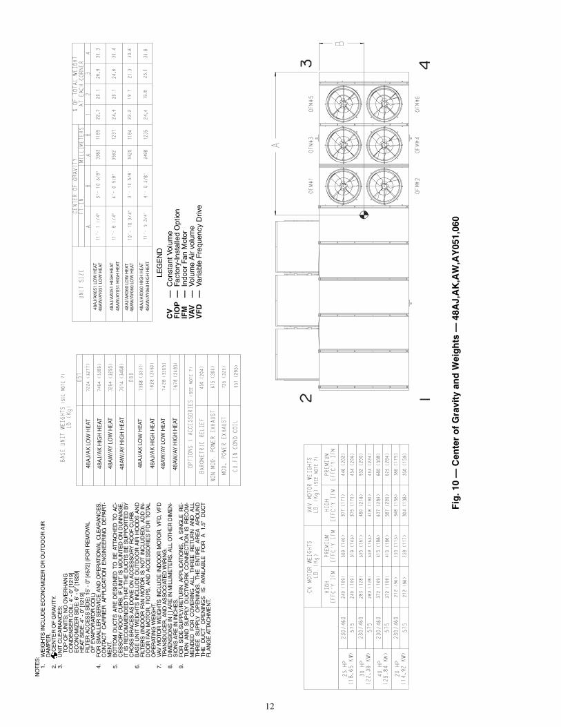
Fig
. 10
— C
ente
r o
f G
ravi
ty a
nd
Wei
gh
ts —
48A
J,A
K,A
W,A
Y05
1,06
0
a50-8102
NO
TE
S:
1.W
EIG
HT
S IN
CLU
DE
EC
ON
OM
IZE
R O
R O
UT
DO
OR
AIR
DA
MP
ER
.2.
C
EN
TE
R O
F G
RA
VIT
Y.3.
UN
IT C
LEA
RA
NC
ES
:
TOP
OF
UN
ITS
: NO
OV
ER
HA
NG
C
ON
DE
NS
ER
CO
IL: 4
’ - 0
“ [12
19]
E
CO
NO
MIZ
ER
SID
E: 6
’ - 0
” [18
29]
H
EAT
SID
E: 4
’’ - 0
” [12
19]
F
ILT
ER
AC
CE
SS
SID
E: 1
5’ -
0” [4
572]
(FO
R R
EM
OVA
L
OF
EVA
PO
RAT
OR
CO
IL)
4.F
OR
SM
ALL
ER
SE
RV
ICE
AN
D O
PE
RAT
ION
AL
CLE
AR
AN
CE
S,
CO
NTA
CT
CA
RR
IER
AP
PLI
CAT
ION
EN
GIN
EE
RIN
G D
EPA
RT
-M
EN
T.5.
BO
TTO
M D
UC
TS
AR
E D
ES
IGN
ED
TO
BE
AT
TAC
HE
D T
O A
C-
CE
SS
OR
Y R
OO
F C
UR
B. I
F U
NIT
IS M
OU
NT
ED
ON
DU
NN
AG
E,
IT IS
RE
CO
MM
EN
DE
D T
HAT
TH
E D
UC
TS
BE
SU
PP
OR
TE
D B
YC
RO
SS
BR
AC
ES
AS
DO
NE
ON
AC
CE
SS
OR
Y R
OO
F C
UR
B.
6.B
AS
E U
NIT
WE
IGH
TS
IN
CLU
DE
OU
TD
OO
R A
IR H
OO
DS
AN
DF
ILT
ER
S (
IND
OO
R F
AN
MO
TOR
IS
NO
T I
NC
LUD
ED
). A
DD
IN
-D
OO
R F
AN
MO
TOR
, F
IOP
S,
AN
D A
CC
ES
SO
RIE
S F
OR
TO
TAL
OP
ER
ATIN
G W
EIG
HT.
7.VA
V M
OTO
R W
EIG
HT
S IN
CLU
DE
IND
OO
R M
OTO
R, V
FD
, V
FD
TR
AN
SD
UC
ER
, AN
D A
SS
OC
IAT
ED
WIR
ING
.8.
DIM
EN
SIO
NS
IN [
] AR
E IN
MIL
LIM
ET
ER
S. A
LL O
TH
ER
DIM
EN
-S
ION
S A
RE
IN IN
CH
ES
.9.
FO
R S
IDE
-SU
PP
LY/R
ET
UR
N A
PP
LIC
ATIO
NS
, A
SIN
GLE
RE
-T
UR
N A
ND
SU
PP
LY D
UC
TW
OR
K C
ON
NE
CT
ION
IS
RE
CO
M-
ME
ND
ED
FO
R C
OV
ER
ING
ALL
TH
RE
E R
ET
UR
N A
ND
ALL
TH
RE
E S
UP
PLY
OP
EN
ING
S.
TH
E
EN
TIR
E
AR
EA
A
RO
UN
DT
HE
D
UC
T
OP
EN
ING
S
IS
AVA
ILA
BLE
F
OR
A
1.
5”
DU
CT
FLA
NG
E A
TTA
CH
ME
NT.
L
EG
EN
DC
V—
Con
stan
t Vol
ume
FIO
P—
Fact
ory-
Inst
alle
d O
ptio
nIF
M—
Indo
or F
an M
otor
VAV
—V
olum
e A
ir vo
lum
eV
FD
—V
aria
ble
Freq
uenc
y D
rive
13
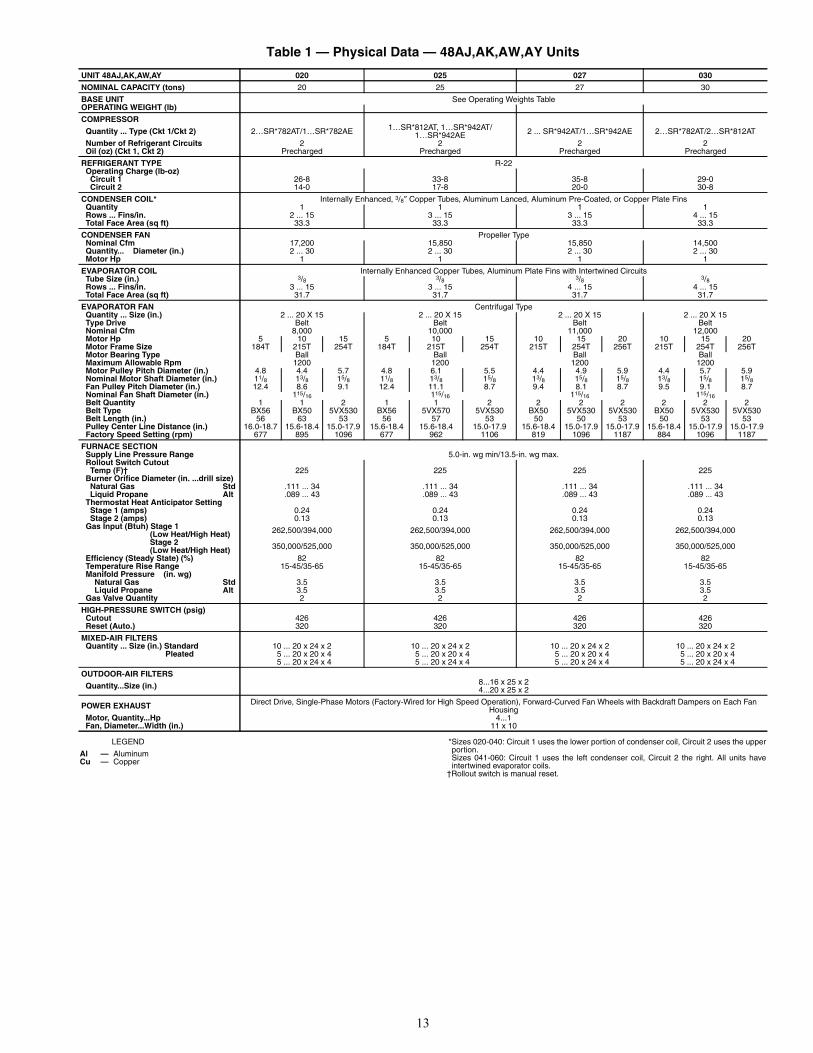
Table 1 — Physical Data — 48AJ,AK,AW,AY Units
LEGEND *Sizes 020-040: Circuit 1 uses the lower portion of condenser coil, Circuit 2 uses the upperportion.Sizes 041-060: Circuit 1 uses the left condenser coil, Circuit 2 the right. All units haveintertwined evaporator coils.
†Rollout switch is manual reset.
UNIT 48AJ,AK,AW,AY 020 025 027 030
NOMINAL CAPACITY (tons) 20 25 27 30
BASE UNIT See Operating Weights TableOPERATING WEIGHT (lb)
COMPRESSOR
Quantity ... Type (Ckt 1/Ckt 2) 2…SR*782AT/1…SR*782AE 1…SR*812AT, 1…SR*942AT/1…SR*942AE 2 ... SR*942AT/1…SR*942AE 2…SR*782AT/2…SR*812AT
Number of Refrigerant Circuits 2 2 2 2 Oil (oz) (Ckt 1, Ckt 2) Precharged Precharged Precharged Precharged
REFRIGERANT TYPE R-22 Operating Charge (lb-oz) Circuit 1 26-8 33-8 35-8 29-0 Circuit 2 14-0 17-8 20-0 30-8
CONDENSER COIL* Internally Enhanced, 3/8″ Copper Tubes, Aluminum Lanced, Aluminum Pre-Coated, or Copper Plate Fins Quantity 1 1 1 1 Rows ... Fins/in. 2 ... 15 3 ... 15 3 ... 15 4 ... 15 Total Face Area (sq ft) 33.3 33.3 33.3 33.3
CONDENSER FAN Propeller Type Nominal Cfm 17,200 15,850 15,850 14,500 Quantity... Diameter (in.) 2 ... 30 2 ... 30 2 ... 30 2 ... 30 Motor Hp 1 1 1 1
EVAPORATOR COIL Internally Enhanced Copper Tubes, Aluminum Plate Fins with Intertwined Circuits Tube Size (in.) 3/8 3/8 3/8 3/8 Rows ... Fins/in. 3 ... 15 3 ... 15 4 ... 15 4 ... 15 Total Face Area (sq ft) 31.7 31.7 31.7 31.7
EVAPORATOR FAN Centrifugal Type Quantity ... Size (in.) 2 ... 20 X 15 2 ... 20 X 15 2 ... 20 X 15 2 ... 20 X 15 Type Drive Belt Belt Belt Belt Nominal Cfm 8,000 10,000 11,000 12,000 Motor Hp 5 10 15 5 10 15 10 15 20 10 15 20 Motor Frame Size 184T 215T 254T 184T 215T 254T 215T 254T 256T 215T 254T 256T Motor Bearing Type Ball Ball Ball Ball Maximum Allowable Rpm 1200 1200 1200 1200 Motor Pulley Pitch Diameter (in.) 4.8 4.4 5.7 4.8 6.1 5.5 4.4 4.9 5.9 4.4 5.7 5.9 Nominal Motor Shaft Diameter (in.) 11/8 13/8 15/8 11/8 13/8 15/8 13/8 15/8 15/8 13/8 15/8 15/8 Fan Pulley Pitch Diameter (in.) 12.4 8.6 9.1 12.4 11.1 8.7 9.4 8.1 8.7 9.5 9.1 8.7 Nominal Fan Shaft Diameter (in.) 115/16 115/16 115/16 115/16 Belt Quantity 1 1 2 1 1 2 2 2 2 2 2 2 Belt Type BX56 BX50 5VX530 BX56 5VX570 5VX530 BX50 5VX530 5VX530 BX50 5VX530 5VX530 Belt Length (in.) 56 63 53 56 57 53 50 50 53 50 53 53 Pulley Center Line Distance (in.) 16.0-18.7 15.6-18.4 15.0-17.9 15.6-18.4 15.6-18.4 15.0-17.9 15.6-18.4 15.0-17.9 15.0-17.9 15.6-18.4 15.0-17.9 15.0-17.9 Factory Speed Setting (rpm) 677 895 1096 677 962 1106 819 1096 1187 884 1096 1187
FURNACE SECTION Supply Line Pressure Range 5.0-in. wg min/13.5-in. wg max. Rollout Switch Cutout Temp (F)† 225 225 225 225 Burner Orifice Diameter (in. ...drill size) Natural Gas Std .111 ... 34 .111 ... 34 .111 ... 34 .111 ... 34 Liquid Propane Alt .089 ... 43 .089 ... 43 .089 ... 43 .089 ... 43 Thermostat Heat Anticipator Setting Stage 1 (amps) 0.24 0.24 0.24 0.24 Stage 2 (amps) 0.13 0.13 0.13 0.13 Gas Input (Btuh) Stage 1 (Low Heat/High Heat) 262,500/394,000 262,500/394,000 262,500/394,000 262,500/394,000
Stage 2 (Low Heat/High Heat) 350,000/525,000 350,000/525,000 350,000/525,000 350,000/525,000
Efficiency (Steady State) (%) 82 82 82 82 Temperature Rise Range 15-45/35-65 15-45/35-65 15-45/35-65 15-45/35-65 Manifold Pressure (in. wg) Natural Gas Std 3.5 3.5 3.5 3.5 Liquid Propane Alt 3.5 3.5 3.5 3.5 Gas Valve Quantity 2 2 2 2
HIGH-PRESSURE SWITCH (psig) Cutout 426 426 426 426 Reset (Auto.) 320 320 320 320
MIXED-AIR FILTERS Quantity ... Size (in.) Standard 10 ... 20 x 24 x 2 10 ... 20 x 24 x 2 10 ... 20 x 24 x 2 10 ... 20 x 24 x 2 Pleated 5 ... 20 x 20 x 4
5 ... 20 x 24 x 45 ... 20 x 20 x 45 ... 20 x 24 x 4
5 ... 20 x 20 x 45 ... 20 x 24 x 4
5 ... 20 x 20 x 45 ... 20 x 24 x 4
OUTDOOR-AIR FILTERS
Quantity...Size (in.) 8...16 x 25 x 24...20 x 25 x 2
POWER EXHAUST Direct Drive, Single-Phase Motors (Factory-Wired for High Speed Operation), Forward-Curved Fan Wheels with Backdraft Dampers on Each Fan Housing
Motor, Quantity...Hp 4...1 Fan, Diameter...Width (in.) 11 x 10
Al — AluminumCu — Copper
14
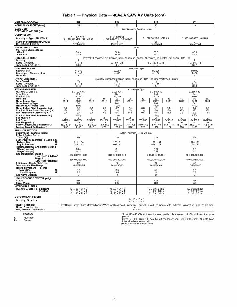
Table 1 — Physical Data — 48AJ,AK,AW,AY Units (cont)
LEGEND *Sizes 020-040: Circuit 1 uses the lower portion of condenser coil, Circuit 2 uses the upperportion.Sizes 041-060: Circuit 1 uses the left condenser coil, Circuit 2 the right. All units haveintertwined evaporator coils.
†Rollout switch is manual reset.
UNIT 48AJ,AK,AW,AY 035 036 040 041
NOMINAL CAPACITY (tons) 35 35 40 40
BASE UNIT See Operating Weights TableOPERATING WEIGHT (lb)
COMPRESSOR
Quantity ... Type (Ckt 1/Ckt 2) 1…SR*812AT, 1…SR*942AT/2…SR*942AT
1…SR*812AT, 1…SR*942AT/2…SR*942AT 2…SR*942AT/2…SM125 2…SR*942AT/2…SM125
Number of Refrigerant Circuits 2 2 2 2 Oil (oz) (Ckt 1, Ckt 2) Precharged Precharged Precharged Precharged
REFRIGERANT TYPE R-22 Operating Charge (lb-oz) Circuit 1 33-0 36-0 36-0 47-0 Circuit 2 38-0 58-0 47-0 47-0
CONDENSER COIL* Internally Enhanced, 3/8″ Copper Tubes, Aluminum Lanced, Aluminum Pre-Coated, or Copper Plate Fins Quantity 1 2 2 2 Rows ... Fins/in. 4 ... 15 2...15/4…15 2 ... 15 / 4 … 15 4...15/4…15 Total Face Area (sq ft) 33.3 66.7 66.7 66.7
CONDENSER FAN Propeller Type Nominal Cfm 14,500 30,000 30,000 30,000 Quantity... Diameter (in.) 2 ... 30 4...30 4 ... 30 4...30 Motor Hp 1 1 1 1
EVAPORATOR COIL Internally Enhanced Copper Tubes, Aluminum Plate Fins with Intertwined Circuits Tube Size (in.) 1/2 1/2 1/2 1/2 Rows ... Fins/in. 6 ... 16 4...17 4 ... 16 4...17 Total Face Area (sq ft) 31.3 31.3 31.3 31.3
EVAPORATOR FAN Centrifugal Type Quantity ... Size (in.) 2 ... 20 X 15 2...20 X 15 2 ... 20 X 15 2...20 X 15 Type Drive Belt Belt Belt Belt Nominal Cfm 14,000 14,000 16,000 16,000 Motor Hp 15 20 25 15 20 25 15 20 25 15 20 25 Motor Frame Size 254T 256T 284T 254T 256T 284T 254T 256T 284T 254T 256T 284T Motor Bearing Type Ball Ball Ball Ball Maximum Allowable Rpm 1300 1300 1300 1300 Motor Pulley Pitch Diameter (in.) 5.1 5.7 6.2 5.3 5.7 7.5 5.3 5.7 7.5 5.3 5.7 7.5 Nominal Motor Shaft Diameter (in.) 15/8 15/8 17/8 15/8 15/8 17/8 15/8 15/8 17/8 15/8 15/8 17/8 Fan Pulley Pitch Diameter (in.) 8.7 8.7 8.7 9.5 9.5 11.1 9.5 9.5 11.1 9.5 9.5 11.1 Nominal Fan Shaft Diameter (in.) 115/16 115/16 115/16 115/16 Belt Quantity 2 2 2 2 2 2 2 2 2 2 2 2 Belt Type 5VX500 5VX530 5VX550 5VX530 5VX550 5VX590 5VX530 5VX550 5VX590 5VX530 5VX550 5VX590 Belt Length (in.) 50 53 55 53 55 59 53 55 59 53 55 59 Pulley Center Line Distance (in.) 15.0-17.9 15.0-17.9 15.0-17.9 15.0-17.9 15.0-17.9 14.6-17.6 15.0-17.9 15.0-17.9 14.6-17.6 15.0-17.9 15.0-17.9 14.6-17.6 Factory Speed Setting (rpm) 1005 1147 1247 976 1050 1182 976 1050 1182 976 1050 1182
FURNACE SECTION Supply Line Pressure Range 5.0-in. wg min/13.5-in. wg max. Rollout Switch Cutout Temp (F)† 225 225 225 225 Burner Orifice Diameter (in ...drill size) Natural Gas Std .111 ... 34 .120...31 .120 ... 31 .120...31 Liquid Propane Alt .089 ... 43 .096...41 .096 ... 41 .096...41 Thermostat Heat Anticipator Setting Stage 1 (amps) 0.24 0.1 0.24 0.1 Stage 2 (amps) 0.13 0.1 0.13 0.1 Gas Input (Btuh) Stage 1 (Low Heat/High Heat) 262,500/394,000 300,000/600,000 300,000/600,000 300,000/600,000
Stage 2 (Low Heat/High Heat) 350,000/525,000 400,000/800,000 400,000/800,000 400,000/800,000
Efficiency (Steady State) (%) 82 82 82 82 Temperature Rise Range 15-45/35-65 10-40/30-60 10-40/3 -60 10-40/30-60 Manifold Pressure (in. wg) Natural Gas Std 3.5 3.5 3.5 3.5 Liquid Propane Alt 3.5 3.5 3.5 3.5 Gas Valve Quantity 2 2 2 2
HIGH-PRESSURE SWITCH (psig) Cutout 426 426 426 426 Reset (Auto.) 320 320 320 320
MIXED-AIR FILTERS Quantity ... Size (in.) Standard 10 ... 20 x 24 x 2 10...20 x 24 x 2
5...20 x 20 x 45...20 x 20 x 4
10 ... 20 x 24 x 2 10...20 x 24 x 25...20 x 20 x 45...20 x 20 x 4
Pleated 5 ... 20 x 20 x 45 ... 20 x 24 x 4
5 ... 20 x 20 x 45 ... 20 x 24 x 4
OUTDOOR-AIR FILTERS
Quantity...Size (in.) 8...16 x 25 x 24...20 x 25 x 2
POWER EXHAUST Direct Drive, Single-Phase Motors (Factory-Wired for High Speed Operation), Forward-Curved Fan Wheels with Backdraft Dampers on Each Fan Housing Motor, Quantity...Hp 4...1 Fan, Diameter...Width (in.) 11 x 10
Al — AluminumCu — Copper
15
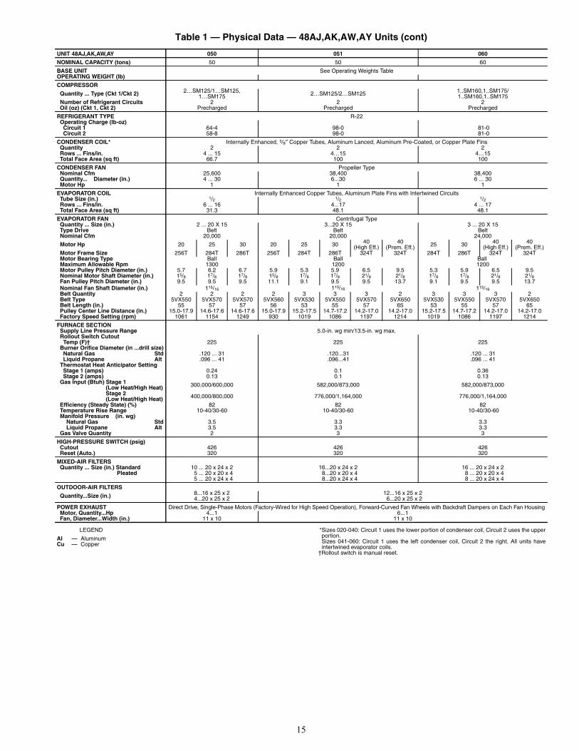
Table 1 — Physical Data — 48AJ,AK,AW,AY Units (cont)
LEGEND *Sizes 020-040: Circuit 1 uses the lower portion of condenser coil, Circuit 2 uses the upperportion.Sizes 041-060: Circuit 1 uses the left condenser coil, Circuit 2 the right. All units haveintertwined evaporator coils.
†Rollout switch is manual reset.
UNIT 48AJ,AK,AW,AY 050 051 060
NOMINAL CAPACITY (tons) 50 50 60
BASE UNIT See Operating Weights TableOPERATING WEIGHT (lb)
COMPRESSOR
Quantity ... Type (Ckt 1/Ckt 2) 2…SM125/1…SM125, 1…SM175 2…SM125/2…SM125 1..SM160,1..SM175/
1..SM160,1..SM175 Number of Refrigerant Circuits 2 2 2 Oil (oz) (Ckt 1, Ckt 2) Precharged Precharged Precharged
REFRIGERANT TYPE R-22 Operating Charge (lb-oz) Circuit 1 64-4 98-0 81-0 Circuit 2 58-8 98-0 81-0
CONDENSER COIL* Internally Enhanced, 3/8″ Copper Tubes, Aluminum Lanced, Aluminum Pre-Coated, or Copper Plate Fins Quantity 2 2 2 Rows ... Fins/in. 4 ... 15 4…15 4…15 Total Face Area (sq ft) 66.7 100 100
CONDENSER FAN Propeller Type Nominal Cfm 25,600 38,400 38,400 Quantity... Diameter (in.) 4 ... 30 6...30 6 ... 30 Motor Hp 1 1 1
EVAPORATOR COIL Internally Enhanced Copper Tubes, Aluminum Plate Fins with Intertwined Circuits Tube Size (in.) 1/2 1/2 1/2 Rows ... Fins/in. 6 ... 16 4...17 4 ... 17 Total Face Area (sq ft) 31.3 48.1 48.1
EVAPORATOR FAN Centrifugal Type Quantity ... Size (in.) 2 ... 20 X 15 3...20 X 15 3 ... 20 X 15 Type Drive Belt Belt Belt Nominal Cfm 20,000 20,000 24,000
Motor Hp 20 25 30 20 25 30 40(High Eff.)
40 (Prem. Eff.) 25 30 40
(High Eff.)40
(Prem. Eff.) Motor Frame Size 256T 284T 286T 256T 284T 286T 324T 324T 284T 286T 324T 324T Motor Bearing Type Ball Ball Ball Maximum Allowable Rpm 1300 1200 1200 Motor Pulley Pitch Diameter (in.) 5.7 6.2 6.7 5.9 5.3 5.9 6.5 9.5 5.3 5.9 6.5 9.5 Nominal Motor Shaft Diameter (in.) 15/8 17/8 17/8 15/8 17/8 17/8 21/8 21/8 17/8 17/8 21/8 21/8 Fan Pulley Pitch Diameter (in.) 9.5 9.5 9.5 11.1 9.1 9.5 9.5 13.7 9.1 9.5 9.5 13.7 Nominal Fan Shaft Diameter (in.) 115/16 115/16 115/16 Belt Quantity 2 2 2 2 3 3 3 2 3 3 3 2 Belt Type 5VX550 5VX570 5VX570 5VX560 5VX530 5VX550 5VX570 5VX650 5VX530 5VX550 5VX570 5VX650 Belt Length (in.) 55 57 57 56 53 55 57 65 53 55 57 65 Pulley Center Line Distance (in.) 15.0-17.9 14.6-17.6 14.6-17.6 15.0-17.9 15.2-17.5 14.7-17.2 14.2-17.0 14.2-17.0 15.2-17.5 14.7-17.2 14.2-17.0 14.2-17.0 Factory Speed Setting (rpm) 1061 1154 1249 930 1019 1086 1197 1214 1019 1086 1197 1214
FURNACE SECTION Supply Line Pressure Range 5.0-in. wg min/13.5-in. wg max. Rollout Switch Cutout Temp (F)† 225 225 225 Burner Orifice Diameter (in ...drill size) Natural Gas Std .120 ... 31 .120...31 .120 ... 31 Liquid Propane Alt .096 ... 41 .096...41 .096 ... 41 Thermostat Heat Anticipator Setting Stage 1 (amps) 0.24 0.1 0.36 Stage 2 (amps) 0.13 0.1 0.13 Gas Input (Btuh) Stage 1 (Low Heat/High Heat) 300,000/600,000 582,000/873,000 582,000/873,000
Stage 2 (Low Heat/High Heat) 400,000/800,000 776,000/1,164,000 776,000/1,164,000
Efficiency (Steady State) (%) 82 82 82 Temperature Rise Range 10-40/30-60 10-40/30-60 10-40/30-60 Manifold Pressure (in. wg) Natural Gas Std 3.5 3.3 3.3 Liquid Propane Alt 3.5 3.3 3.3 Gas Valve Quantity 2 3 3
HIGH-PRESSURE SWITCH (psig) Cutout 426 426 426 Reset (Auto.) 320 320 320
MIXED-AIR FILTERS Quantity ... Size (in.) Standard 10 ... 20 x 24 x 2 16...20 x 24 x 2
8...20 x 20 x 48...20 x 24 x 4
16 ... 20 x 24 x 2 Pleated 5 ... 20 x 20 x 4
5 ... 20 x 24 x 48 ... 20 x 20 x 48 ... 20 x 24 x 4
OUTDOOR-AIR FILTERS
Quantity...Size (in.) 8...16 x 25 x 24...20 x 25 x 2
12...16 x 25 x 26...20 x 25 x 2
POWER EXHAUST Direct Drive, Single-Phase Motors (Factory-Wired for High Speed Operation), Forward-Curved Fan Wheels with Backdraft Dampers on Each Fan Housing Motor, Quantity...Hp 4...1
11 x 106...1
11 x 10 Fan, Diameter...Width (in.)
Al — AluminumCu — Copper
16
50A
J/A
K02
046
07
2090
87.7
22
2770
.9
1801
42.0
10
6748
AJ/
AK
D02
0 46
97
2131
87.7
22
2771
.9
1826
42.5
10
8048
AJ/
AK
E02
047
7721
6787
.7
2227
72.8
18
4941
.0
1041
50A
W/A
Y02
0 46
8521
25
87.7
2227
70.9
18
0142
.0
1067
48A
W/A
YD
020
4737
2149
87
.722
2771
.9
1826
42.5
10
8048
AW
/AY
E02
0 48
1721
85
87.7
2227
72.8
18
4941
.0
1041
50A
J/A
K02
546
80
2123
87.7
22
2768
.0
1727
43.9
11
15
48A
J/A
KD
025
4770
21
64
87.7
2227
69.1
17
55
44.3
1125
48
AJ/
AK
E02
548
50
2200
87.7
2227
69.6
17
6844
.611
33
50A
W/A
Y02
547
58
2158
87.7
22
2768
.0
1727
43.9
11
15
48A
W/A
YD
025
4810
2182
87
.722
2769
.1
1755
44
.311
25
48A
W/A
YE
025
4890
22
1887
.722
2769
.6
1768
44.6
1133
50
AJ/
AK
027
4873
22
1087
.722
2768
.0
1727
43.9
11
15
48A
J/A
KD
027
4963
22
5187
.722
2769
.1
1755
44
.311
25
48A
J/A
KE
027
5043
22
8787
.722
2769
.6
1768
44.6
1133
50
AW
/AY
027
4951
22
4687
.722
2768
.0
1727
43.9
11
15
48A
W/A
YD
027
5003
2269
87.7
22
2769
.1
1755
44
.311
25
48A
W/A
YE
027
5083
23
0687
.7
2227
69.6
17
6844
.611
33
50A
J/A
K03
050
23
2278
87.7
2227
68.0
17
2743
.6
1107
48
AJ/
AK
D03
0 51
13
2319
87.7
22
2769
.1
1755
44
.011
18
48A
J/A
KE
030
5193
23
5687
.7
2227
69.6
17
6844
.311
2550
AW
/AY
030
5101
2314
87
.722
2768
.0
1727
43.6
11
07
48A
W/A
YD
030
5153
2337
87
.7
2227
69.1
17
55
44.0
1118
48
AW
/AY
E03
0 52
3323
7487
.7
2227
69.6
17
6844
.311
2550
AJ/
AK
035
5229
23
72
87.7
2227
68.3
17
3546
.5
1181
48
AJ/
AK
D03
5 54
3424
65
87.7
2227
69.4
17
6346
.9
1191
48
AJ/
AK
E03
555
9425
37
87.7
2227
70.0
17
7847
.2
1199
50A
W/A
Y03
554
22
2459
87.7
22
2768
.3
1735
46.5
11
81
48A
W/A
YD
035
5474
2483
87
.722
2769
.4
1763
46.9
11
91
48A
W/A
YE
035
5634
25
5687
.7
2227
70.0
17
7847
.2
1199
50A
J/A
K03
656
09
2544
87.7
2227
93.4
23
7245
.3
1152
48
AJ/
AK
D03
6 58
14
2637
87.7
22
2794
.8
2409
45.8
11
63
48A
J/A
KE
036
5974
27
1087
.7
2227
96.3
24
4646
.1
1172
50
AW
/AY
036
5802
26
3287
.7
2227
93.3
23
7045
.4
1153
48
AW
/AY
D03
6 58
5426
55
87.7
2227
94.8
24
0845
.8
1163
48
AW
/AY
E03
660
14
2728
87.7
22
2796
.3
2446
46.1
11
72
50A
J/A
K04
057
69
2617
87.7
22
2790
.8
2306
46.5
11
81
48A
J/A
KD
040
5974
27
1087
.7
2227
92.3
23
44
46.9
1191
48A
J/A
KE
040
6134
27
8287
.7
2227
93.8
23
8347
.2
1199
50A
W/A
Y04
0 59
6227
04
87.7
2227
90.8
23
0646
.5
1181
48
AW
/AY
D04
0 60
1427
28
87.7
2227
92.3
23
44
46.9
1191
48A
W/A
YE
040
6174
2801
87
.722
2793
.8
2383
47.2
11
9950
AJ/
AK
041
5885
26
69
87.7
22
2789
.0
2261
45.6
11
58
48A
J/A
KD
041
6090
2762
87
.722
2790
.5
2300
46
.011
6948
AJ/
AK
E04
162
50
2835
87.7
22
2792
.1
2338
46.3
11
7750
AW
/AY
041
6078
27
5787
.7
2227
89.1
22
6245
.6
1159
48
AW
/AY
D04
1 61
3027
81
87.7
2227
90.6
23
00
46.0
1169
48A
W/A
YE
041
6290
28
5387
.7
2227
92.1
23
3946
.3
1177
50A
J/A
K05
063
38
2875
87
.722
2789
.2
2266
46
.111
7148
AJ/
AK
D05
0 65
43
2968
87.7
22
2790
.7
2304
46.5
11
81
48A
J/A
KE
050
6703
30
4087
.7
2227
92.2
23
4246
.8
1189
50
AW
/AY
050
6531
2962
87
.722
2789
.2
2266
46
.111
7148
AW
/AY
D05
0 65
8329
86
87.7
2227
90.7
23
0446
.5
1181
48
AW
/AY
E05
0 67
4330
59
87.7
2227
92.2
23
4246
.8
1189
50
AJ/
AK
051
8544
38
7616
1.7
4106
126.
0 32
00
44.6
1133
48A
J/A
KD
051
8674
39
3516
1.7
4106
133.
2 33
8346
.6
1185
48
AJ/
AK
E05
189
14
4043
161.
7 41
0614
0.2
3562
48.7
12
3750
AW
/AY
051
8759
39
7316
1.7
4106
125.
9 31
9844
.611
33
48A
W/A
YD
051
8714
3953
16
1.7
4106
13
3.2
3382
46.6
11
85
48A
W/A
YE
051
8964
40
6616
1.7
4106
14
0.2
3562
48
.712
37
50A
J/A
K06
087
08
3950
161.
7 41
0612
3.6
3139
44.6
1133
48
AJ/
AK
D06
0 88
3840
09
161.
7 41
0613
0.7
3320
46.6
11
84
48A
J/A
KE
060
9078
41
1816
1.7
4106
137.
7 34
9848
.6
1234
50A
W/A
Y06
0 89
2340
47
161.
7 41
06
123.
6 31
39
44.6
1133
48A
W/A
YD
060
8878
4027
16
1.7
4106
13
0.7
3320
46.6
11
84
48A
W/A
YE
060
9128
4140
16
1.7
4106
13
7.7
3498
48
.612
34
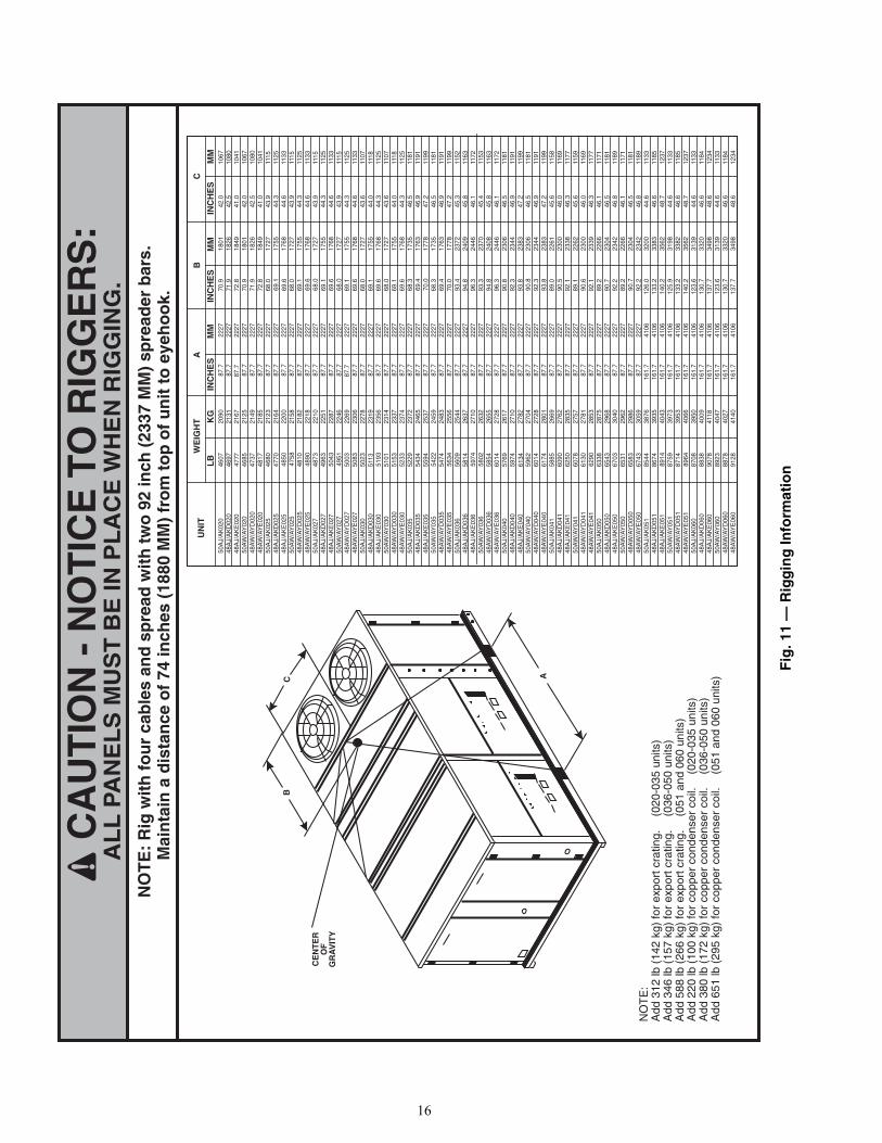
NO
TE
: R
ig w
ith
fo
ur
cab
les
and
sp
read
wit
h t
wo
92
inch
(23
37 M
M)
spre
ader
bar
s.
Mai
nta
in a
dis
tan
ce o
f 74
inch
es (
1880
MM
) fr
om
to
p o
f u
nit
to
eye
ho
ok.
CA
UT
ION
- N
OT
ICE
TO
RIG
GE
RS
:A
LL
PA
NE
LS
MU
ST
BE
IN P
LA
CE
WH
EN
RIG
GIN
G.
CE
NT
ER
OF
GR
AV
ITY
WE
IGH
TB
AC
LB
KG
INC
HE
SM
MIN
CH
ES
MM
INC
HE
SM
M
B
AC
NO
TE
:A
dd 3
12 lb
(14
2 kg
) fo
r ex
port
cra
ting.
(0
20-0
35 u
nits
)A
dd 3
46 lb
(15
7 kg
) fo
r ex
port
cra
ting.
(0
36-0
50 u
nits
)A
dd 5
88 lb
(26
6 kg
) fo
r ex
port
cra
ting.
(0
51 a
nd 0
60 u
nits
)A
dd 2
20 lb
(10
0 kg
) fo
r co
pper
con
dens
er c
oil.
(020
-035
uni
ts)
Add
380
lb (
172
kg)
for
copp
er c
onde
nser
coi
l. (0
36-0
50 u
nits
)A
dd 6
51 lb
(29
5 kg
) fo
r co
pper
con
dens
er c
oil.
(051
and
060
uni
ts)
UN
IT
Fig
. 11
— R
igg
ing
Info
rmat
ion
a48-8246
17
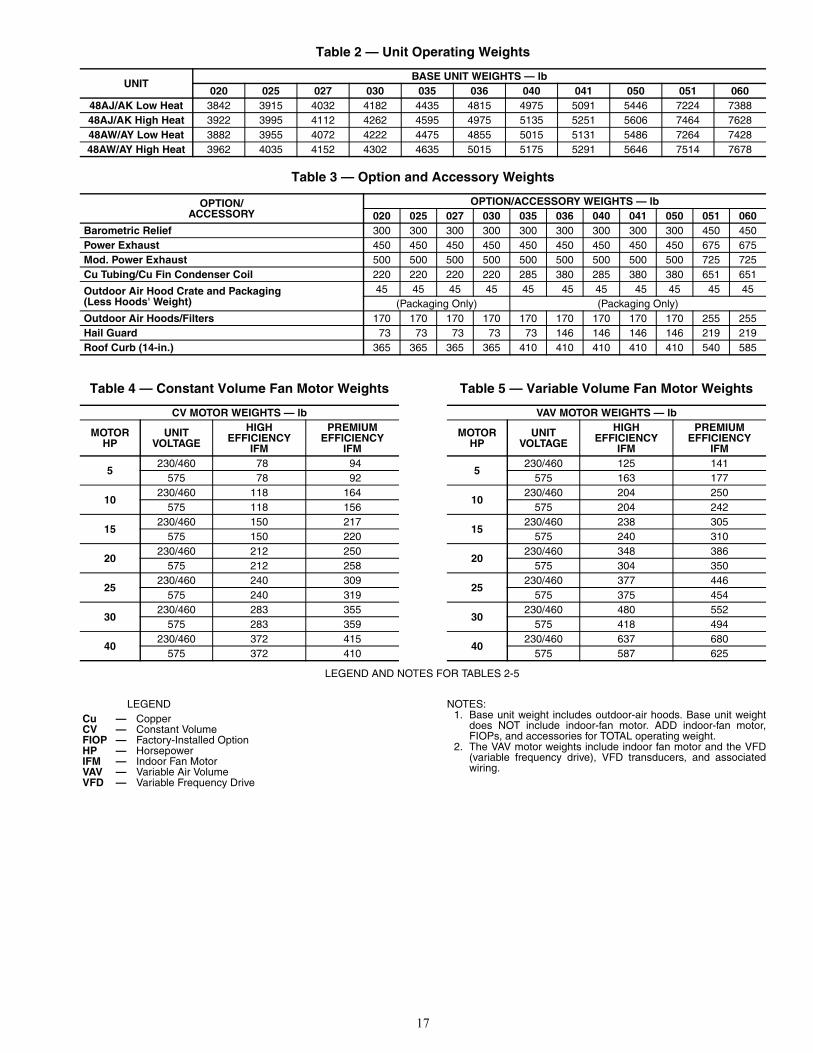
Table 2 — Unit Operating Weights
Table 3 — Option and Accessory Weights
Table 4 — Constant Volume Fan Motor Weights
LEGEND
Table 5 — Variable Volume Fan Motor Weights
NOTES:1. Base unit weight includes outdoor-air hoods. Base unit weight
does NOT include indoor-fan motor. ADD indoor-fan motor,FIOPs, and accessories for TOTAL operating weight.
2. The VAV motor weights include indoor fan motor and the VFD(variable frequency drive), VFD transducers, and associatedwiring.
UNITBASE UNIT WEIGHTS — lb
020 025 027 030 035 036 040 041 050 051 06048AJ/AK Low Heat 3842 3915 4032 4182 4435 4815 4975 5091 5446 7224 738848AJ/AK High Heat 3922 3995 4112 4262 4595 4975 5135 5251 5606 7464 762848AW/AY Low Heat 3882 3955 4072 4222 4475 4855 5015 5131 5486 7264 742848AW/AY High Heat 3962 4035 4152 4302 4635 5015 5175 5291 5646 7514 7678
OPTION/ACCESSORY
OPTION/ACCESSORY WEIGHTS — lb020 025 027 030 035 036 040 041 050 051 060
Barometric Relief 300 300 300 300 300 300 300 300 300 450 450Power Exhaust 450 450 450 450 450 450 450 450 450 675 675Mod. Power Exhaust 500 500 500 500 500 500 500 500 500 725 725Cu Tubing/Cu Fin Condenser Coil 220 220 220 220 285 380 285 380 380 651 651
Outdoor Air Hood Crate and Packaging(Less Hoods' Weight)
45 45 45 45 45 45 45 45 45 45 45(Packaging Only) (Packaging Only)
Outdoor Air Hoods/Filters 170 170 170 170 170 170 170 170 170 255 255Hail Guard 73 73 73 73 73 146 146 146 146 219 219Roof Curb (14-in.) 365 365 365 365 410 410 410 410 410 540 585
CV MOTOR WEIGHTS — lb
MOTORHP
UNITVOLTAGE
HIGHEFFICIENCY
IFM
PREMIUMEFFICIENCY
IFM
5230/460 78 94
575 78 92
10230/460 118 164
575 118 156
15230/460 150 217
575 150 220
20230/460 212 250
575 212 258
25230/460 240 309
575 240 319
30230/460 283 355
575 283 359
40230/460 372 415
575 372 410
Cu — CopperCV — Constant VolumeFIOP — Factory-Installed OptionHP — HorsepowerIFM — Indoor Fan MotorVAV — Variable Air VolumeVFD — Variable Frequency Drive
VAV MOTOR WEIGHTS — lb
MOTORHP
UNITVOLTAGE
HIGHEFFICIENCY
IFM
PREMIUMEFFICIENCY
IFM
5230/460 125 141
575 163 177
10230/460 204 250
575 204 242
15230/460 238 305
575 240 310
20230/460 348 386
575 304 350
25230/460 377 446
575 375 454
30230/460 480 552
575 418 494
40230/460 637 680
575 587 625
LEGEND AND NOTES FOR TABLES 2-5
18
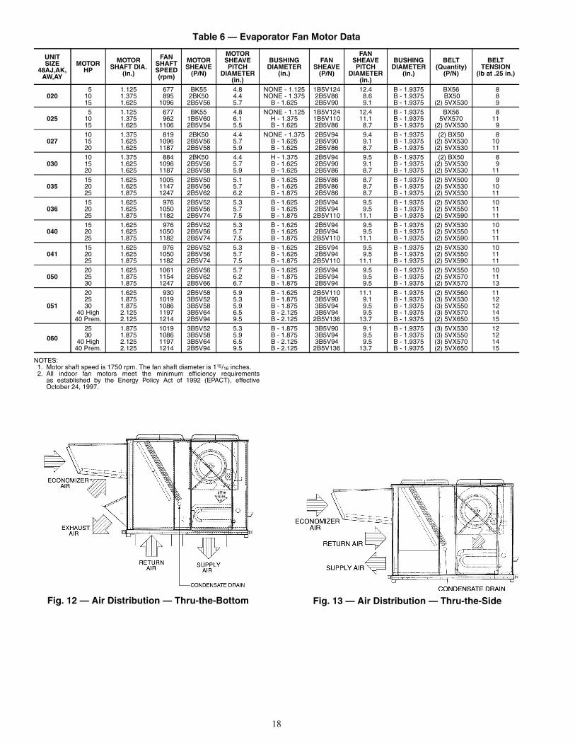
Table 6 — Evaporator Fan Motor Data
NOTES:1. Motor shaft speed is 1750 rpm. The fan shaft diameter is 115/16 inches.2. All indoor fan motors meet the minimum efficiency requirements
as established by the Energy Policy Act of 1992 (EPACT), effectiveOctober 24, 1997.
UNITSIZE
48AJ,AK,AW,AY
MOTORHP
MOTORSHAFT DIA.
(in.)
FANSHAFTSPEED(rpm)
MOTORSHEAVE
(P/N)
MOTORSHEAVEPITCH
DIAMETER(in.)
BUSHINGDIAMETER
(in.)
FANSHEAVE
(P/N)
FANSHEAVEPITCH
DIAMETER(in.)
BUSHINGDIAMETER
(in.)
BELT(Quantity)
(P/N)
BELTTENSION
(lb at .25 in.)
0205 1.125 677 BK55 4.8 NONE - 1.125 1B5V124 12.4 B - 1.9375 BX56 8
10 1.375 895 2BK50 4.4 NONE - 1.375 2B5V86 8.6 B - 1.9375 BX50 815 1.625 1096 2B5V56 5.7 B - 1.625 2B5V90 9.1 B - 1.9375 (2) 5VX530 9
0255 1.125 677 BK55 4.8 NONE - 1.125 1B5V124 12.4 B - 1.9375 BX56 8
10 1.375 962 1B5V60 6.1 H - 1.375 1B5V110 11.1 B - 1.9375 5VX570 1115 1.625 1106 2B5V54 5.5 B - 1.625 2B5V86 8.7 B - 1.9375 (2) 5VX530 9
02710 1.375 819 2BK50 4.4 NONE - 1.375 2B5V94 9.4 B - 1.9375 (2) BX50 815 1.625 1096 2B5V56 5.7 B - 1.625 2B5V90 9.1 B - 1.9375 (2) 5VX530 1020 1.625 1187 2B5V58 5.9 B - 1.625 2B5V86 8.7 B - 1.9375 (2) 5VX530 11
03010 1.375 884 2BK50 4.4 H - 1.375 2B5V94 9.5 B - 1.9375 (2) BX50 815 1.625 1096 2B5V56 5.7 B - 1.625 2B5V90 9.1 B - 1.9375 (2) 5VX530 920 1.625 1187 2B5V58 5.9 B - 1.625 2B5V86 8.7 B - 1.9375 (2) 5VX530 11
03515 1.625 1005 2B5V50 5.1 B - 1.625 2B5V86 8.7 B - 1.9375 (2) 5VX500 920 1.625 1147 2B5V56 5.7 B - 1.625 2B5V86 8.7 B - 1.9375 (2) 5VX530 1025 1.875 1247 2B5V62 6.2 B - 1.875 2B5V86 8.7 B - 1.9375 (2) 5VX530 11
03615 1.625 976 2B5V52 5.3 B - 1.625 2B5V94 9.5 B - 1.9375 (2) 5VX530 1020 1.625 1050 2B5V56 5.7 B - 1.625 2B5V94 9.5 B - 1.9375 (2) 5VX550 1125 1.875 1182 2B5V74 7.5 B - 1.875 2B5V110 11.1 B - 1.9375 (2) 5VX590 11
04015 1.625 976 2B5V52 5.3 B - 1.625 2B5V94 9.5 B - 1.9375 (2) 5VX530 1020 1.625 1050 2B5V56 5.7 B - 1.625 2B5V94 9.5 B - 1.9375 (2) 5VX550 1125 1.875 1182 2B5V74 7.5 B - 1.875 2B5V110 11.1 B - 1.9375 (2) 5VX590 11
04115 1.625 976 2B5V52 5.3 B - 1.625 2B5V94 9.5 B - 1.9375 (2) 5VX530 1020 1.625 1050 2B5V56 5.7 B - 1.625 2B5V94 9.5 B - 1.9375 (2) 5VX550 1125 1.875 1182 2B5V74 7.5 B - 1.875 2B5V110 11.1 B - 1.9375 (2) 5VX590 11
05020 1.625 1061 2B5V56 5.7 B - 1.625 2B5V94 9.5 B - 1.9375 (2) 5VX550 1025 1.875 1154 2B5V62 6.2 B - 1.875 2B5V94 9.5 B - 1.9375 (2) 5VX570 1130 1.875 1247 2B5V66 6.7 B - 1.875 2B5V94 9.5 B - 1.9375 (2) 5VX570 13
051
20 1.625 930 2B5V58 5.9 B - 1.625 2B5V110 11.1 B - 1.9375 (2) 5VX560 1125 1.875 1019 3B5V52 5.3 B - 1.875 3B5V90 9.1 B - 1.9375 (3) 5VX530 1230 1.875 1086 3B5V58 5.9 B - 1.875 3B5V94 9.5 B - 1.9375 (3) 5VX550 12
40 High 2.125 1197 3B5V64 6.5 B - 2.125 3B5V94 9.5 B - 1.9375 (3) 5VX570 1440 Prem. 2.125 1214 2B5V94 9.5 B - 2.125 2B5V136 13.7 B - 1.9375 (2) 5VX650 15
060
25 1.875 1019 3B5V52 5.3 B - 1.875 3B5V90 9.1 B - 1.9375 (3) 5VX530 1230 1.875 1086 3B5V58 5.9 B - 1.875 3B5V94 9.5 B - 1.9375 (3) 5VX550 12
40 High 2.125 1197 3B5V64 6.5 B - 2.125 3B5V94 9.5 B - 1.9375 (3) 5VX570 1440 Prem. 2.125 1214 2B5V94 9.5 B - 2.125 2B5V136 13.7 B - 1.9375 (2) 5VX650 15
Fig. 12 — Air Distribution — Thru-the-Bottom Fig. 13 — Air Distribution — Thru-the-Side
a48-8241 a48-8242
19
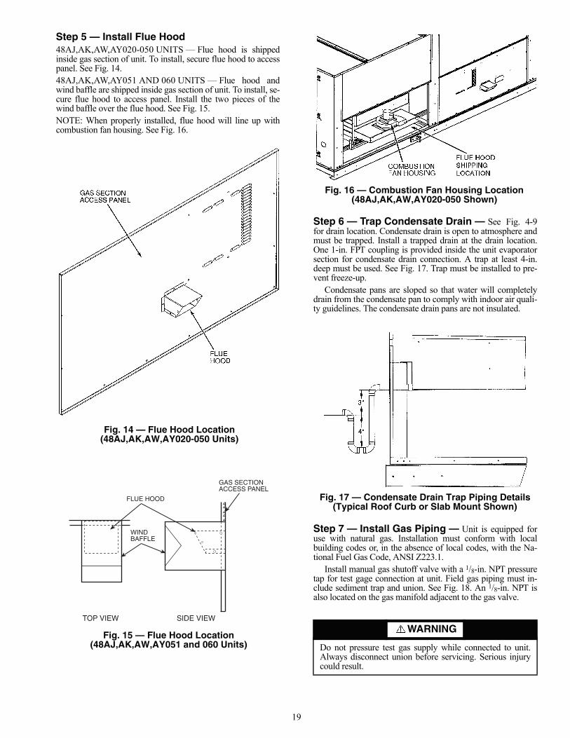
Step 5 — Install Flue Hood48AJ,AK,AW,AY020-050 UNITS — Flue hood is shippedinside gas section of unit. To install, secure flue hood to accesspanel. See Fig. 14.48AJ,AK,AW,AY051 AND 060 UNITS — Flue hood andwind baffle are shipped inside gas section of unit. To install, se-cure flue hood to access panel. Install the two pieces of thewind baffle over the flue hood. See Fig. 15.NOTE: When properly installed, flue hood will line up withcombustion fan housing. See Fig. 16.
Step 6 — Trap Condensate Drain — See Fig. 4-9for drain location. Condensate drain is open to atmosphere andmust be trapped. Install a trapped drain at the drain location.One 1-in. FPT coupling is provided inside the unit evaporatorsection for condensate drain connection. A trap at least 4-in.deep must be used. See Fig. 17. Trap must be installed to pre-vent freeze-up.
Condensate pans are sloped so that water will completelydrain from the condensate pan to comply with indoor air quali-ty guidelines. The condensate drain pans are not insulated.
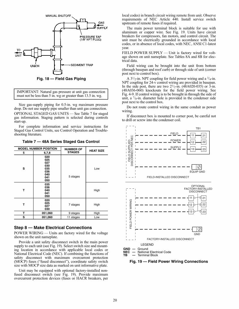
Step 7 — Install Gas Piping — Unit is equipped foruse with natural gas. Installation must conform with localbuilding codes or, in the absence of local codes, with the Na-tional Fuel Gas Code, ANSI Z223.1.
Install manual gas shutoff valve with a 1/8-in. NPT pressuretap for test gage connection at unit. Field gas piping must in-clude sediment trap and union. See Fig. 18. An 1/8-in. NPT isalso located on the gas manifold adjacent to the gas valve.
WARNING
Do not pressure test gas supply while connected to unit.Always disconnect union before servicing. Serious injurycould result.
FLUE HOOD
GAS SECTIONACCESS PANEL
WINDBAFFLE
TOP VIEW SIDE VIEW
Fig. 14 — Flue Hood Location (48AJ,AK,AW,AY020-050 Units)
Fig. 15 — Flue Hood Location(48AJ,AK,AW,AY051 and 060 Units)
a48-3712
a48-4076
Fig. 16 — Combustion Fan Housing Location(48AJ,AK,AW,AY020-050 Shown)
a48-3823
Fig. 17 — Condensate Drain Trap Piping Details(Typical Roof Curb or Slab Mount Shown)
a48-3714
20
Size gas-supply piping for 0.5-in. wg maximum pressuredrop. Do not use supply pipe smaller than unit gas connection.OPTIONAL STAGED GAS UNITS — See Table 7 for stagedgas information. Staging pattern is selected during controlsstart-up.
For complete information and service instructions forStaged Gas Control Units, see Control Operation and Trouble-shooting literature.
Table 7 — 48A Series Staged Gas Control
Step 8 — Make Electrical ConnectionsPOWER WIRING — Units are factory wired for the voltageshown on the unit nameplate.
Provide a unit safety disconnect switch in the main powersupply to each unit (see Fig. 19). Select switch size and mount-ing location in accordance with applicable local codes orNational Electrical Code (NEC). If combining the functions ofsafety disconnect with maximum overcurrent protection(MOCP) fuses (“fused disconnect”), coordinate safety switchsize with MOCP size data as marked on unit informative plate.
Unit may be equipped with optional factory-installed non-fused disconnect switch (see Fig. 19). Provide maximumovercurrent protection devices (fuses or HACR breakers, per
local codes) in branch circuit wiring remote from unit. Observerequirements of NEC Article 440. Install service switchupstream of remote fuses if required.
The main power terminal block is suitable for use withaluminum or copper wire. See Fig. 19. Units have circuitbreakers for compressors, fan motors, and control circuit. Theunit must be electrically grounded in accordance with localcodes, or in absence of local codes, with NEC, ANSI C1-latestyear.FIELD POWER SUPPLY — Unit is factory wired for volt-age shown on unit nameplate. See Tables 8A and 8B for elec-trical data.
Field wiring can be brought into the unit from bottom(through basepan and roof curb) or through side of unit (cornerpost next to control box).
A 31/2-in. NPT coupling for field power wiring and a 3/4-in.NPT coupling for 24-v control wiring are provided in basepan.In the side post, there are two 21/2-in. (48A020-035) or 3-in.(48A036-060) knockouts for the field power wiring. SeeFig. 4-9. If control wiring is to be brought in through the side ofunit, a 7/8-in. diameter hole is provided in the condenser sidepost next to the control box.
Do not route control wiring in the same conduit as powerwiring.
If disconnect box is mounted to corner post, be careful notto drill or screw into the condenser coil.
IMPORTANT: Natural gas pressure at unit gas connectionmust not be less than 5 in. wg or greater than 13.5 in. wg.
MODEL NUMBER POSITION NUMBER OFSTAGES HEAT SIZE
5 6,7,8
S
020025027030035036040041050
5 stages
Low
T
035036040041050
High
T
020025027030
7 stages High
T 051,060 9 stages HighS 051,060 11 stages Low
Fig. 18 — Field Gas Piping
a48-2524
FIE
LD S
UP
PLI
ED
DIS
CO
NN
EC
T P
ER
NE
CFIELD
POWER
SUPPLY
11 21
22
2313
12
TB1
EQUIP GND
FIE
LD P
OW
ER
WIR
ING
11 21
22
2313
12
GND
OPTIONALFACTORY-INSTALLED
DISCONNECT
FIELD-INSTALLED DISCONNECT
FACTORY-INSTALLED DISCONNECT
LEGENDGND — GroundNEC — National Electrical CodeTB — Terminal Block
Fig. 19 — Field Power Wiring Connections
a48-6977
21
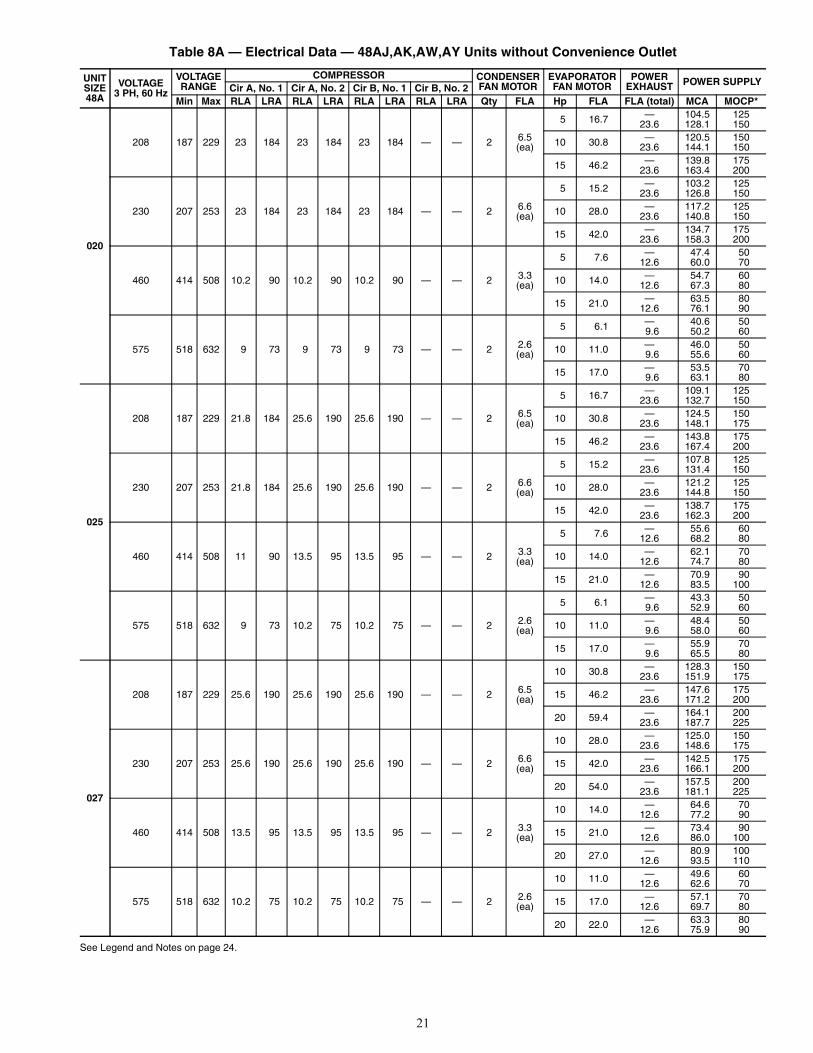
Table 8A — Electrical Data — 48AJ,AK,AW,AY Units without Convenience Outlet
See Legend and Notes on page 24.
UNITSIZE48A
VOLTAGE3 PH, 60 Hz
VOLTAGERANGE
COMPRESSOR CONDENSERFAN MOTOR
EVAPORATORFAN MOTOR
POWEREXHAUST POWER SUPPLY
Cir A, No. 1 Cir A, No. 2 Cir B, No. 1 Cir B, No. 2Min Max RLA LRA RLA LRA RLA LRA RLA LRA Qty FLA Hp FLA FLA (total) MCA MOCP*
020
208 187 229 23 184 23 184 23 184 — — 2 6.5(ea)
5 16.7 — 104.5 12523.6 128.1 150
10 30.8 — 120.5 15023.6 144.1 150
15 46.2 — 139.8 17523.6 163.4 200
230 207 253 23 184 23 184 23 184 — — 2 6.6(ea)
5 15.2 — 103.2 12523.6 126.8 150
10 28.0 — 117.2 12523.6 140.8 150
15 42.0 — 134.7 17523.6 158.3 200
460 414 508 10.2 90 10.2 90 10.2 90 — — 2 3.3(ea)
5 7.6 — 47.4 5012.6 60.0 70
10 14.0 — 54.7 6012.6 67.3 80
15 21.0 — 63.5 8012.6 76.1 90
575 518 632 9 73 9 73 9 73 — — 2 2.6(ea)
5 6.1 — 40.6 509.6 50.2 60
10 11.0 — 46.0 509.6 55.6 60
15 17.0 — 53.5 709.6 63.1 80
025
208 187 229 21.8 184 25.6 190 25.6 190 — — 2 6.5(ea)
5 16.7 — 109.1 12523.6 132.7 150
10 30.8 — 124.5 15023.6 148.1 175
15 46.2 — 143.8 17523.6 167.4 200
230 207 253 21.8 184 25.6 190 25.6 190 — — 2 6.6(ea)
5 15.2 — 107.8 12523.6 131.4 150
10 28.0 — 121.2 12523.6 144.8 150
15 42.0 — 138.7 17523.6 162.3 200
460 414 508 11 90 13.5 95 13.5 95 — — 2 3.3(ea)
5 7.6 — 55.6 6012.6 68.2 80
10 14.0 — 62.1 7012.6 74.7 80
15 21.0 — 70.9 9012.6 83.5 100
575 518 632 9 73 10.2 75 10.2 75 — — 2 2.6(ea)
5 6.1 — 43.3 509.6 52.9 60
10 11.0 — 48.4 509.6 58.0 60
15 17.0 — 55.9 709.6 65.5 80
027
208 187 229 25.6 190 25.6 190 25.6 190 — — 2 6.5(ea)
10 30.8 — 128.3 15023.6 151.9 175
15 46.2 — 147.6 17523.6 171.2 200
20 59.4 — 164.1 20023.6 187.7 225
230 207 253 25.6 190 25.6 190 25.6 190 — — 2 6.6(ea)
10 28.0 — 125.0 15023.6 148.6 175
15 42.0 — 142.5 17523.6 166.1 200
20 54.0 — 157.5 20023.6 181.1 225
460 414 508 13.5 95 13.5 95 13.5 95 — — 2 3.3(ea)
10 14.0 — 64.6 7012.6 77.2 90
15 21.0 — 73.4 9012.6 86.0 100
20 27.0 — 80.9 10012.6 93.5 110
575 518 632 10.2 75 10.2 75 10.2 75 — — 2 2.6(ea)
10 11.0 — 49.6 6012.6 62.6 70
15 17.0 — 57.1 7012.6 69.7 80
20 22.0 — 63.3 8012.6 75.9 90
22
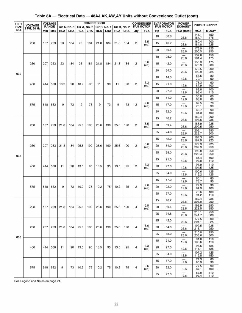
Table 8A — Electrical Data — 48AJ,AK,AW,AY Units without Convenience Outlet (cont)
See Legend and Notes on page 24.
UNITSIZE48A
VOLTAGE3 PH, 60 Hz
VOLTAGERANGE
COMPRESSOR CONDENSERFAN MOTOR
EVAPORATORFAN MOTOR
POWEREXHAUST POWER SUPPLY
Cir A, No. 1 Cir A, No. 2 Cir B, No. 1 Cir B, No. 2Min Max RLA LRA RLA LRA RLA LRA RLA LRA Qty FLA Hp FLA FLA (total) MCA MOCP*
030
208 187 229 23 184 23 184 21.8 184 21.8 184 2 6.5(ea)
10 30.8 — 141.1 15023.6 164.7 175
15 46.2 — 160.4 20023.6 184.0 225
20 59.4 — 176.9 22523.6 200.5 250
230 207 253 23 184 23 184 21.8 184 21.8 184 2 6.6(ea)
10 28.0 — 137.8 15023.6 161.4 175
15 42.0 — 155.3 17523.6 178.9 200
20 54.0 — 170.5 20023.6 193.9 225
460 414 508 10.2 90 10.2 90 11 90 11 90 2 3.3(ea)
10 14.0 — 66.5 8012.6 79.1 90
15 21.0 — 75.3 9012.6 87.9 100
20 27.0 — 82.8 10012.6 95.4 110
575 518 632 9 73 9 73 9 73 9 73 2 2.6(ea)
10 11.0 — 55.0 6012.6 68.0 80
15 17.0 — 62.5 7012.6 75.1 90
20 22.0 — 68.7 9012.6 81.3 100
035
208 187 229 21.8 184 25.6 190 25.6 190 25.6 190 2 6.5(ea)
15 46.2 — 169.4 20023.6 193.6 225
20 59.4 — 185.9 22523.6 209.5 250
25 74.8 — 205.1 25023.6 228.7 300
230 207 253 21.8 184 25.6 190 25.6 190 25.6 190 2 6.6(ea)
15 42.0 — 164.3 20023.6 187.9 225
20 54.0 — 179.3 22523.6 202.9 250
25 68.0 — 196.8 25023.6 220.4 250
460 414 508 11 90 13.5 95 13.5 95 13.5 95 2 3.3(ea)
15 21.0 — 84.4 10012.6 97.0 110
20 27.0 — 91.9 11012.6 104.5 125
25 34.0 — 100.6 12512.6 113.2 125
575 518 632 9 73 10.2 75 10.2 75 10.2 75 2 2.6(ea)
15 17.0 — 66.1 8012.6 78.7 90
20 22.0 — 72.3 9012.6 84.9 100
25 27.0 — 78.6 10012.6 91.2 110
036
208 187 229 21.8 184 25.6 190 25.6 190 25.6 190 4 6.5(ea)
15 46.2 — 182.4 22523.6 206.0 250
20 59.4 — 198.9 25023.6 222.5 250
25 74.8 — 218.1 25023.6 241.7 300
230 207 253 21.8 184 25.6 190 25.6 190 25.6 190 4 6.6(ea)
15 42.0 — 177.5 20023.6 201.1 225
20 54.0 — 192.5 22523.6 216.1 250
25 68.0 — 210.0 25023.6 233.6 300
460 414 508 11 90 13.5 95 13.5 95 13.5 95 4 3.3(ea)
15 21.0 — 91.0 11012.6 103.6 110
20 27.0 — 98.5 12512.6 111.1 125
25 34.0 — 107.2 12512.6 119.8 150
575 518 632 9 73 10.2 75 10.2 75 10.2 75 4 2.6(ea)
15 17.0 — 71.3 809.6 80.9 90
20 22.0 — 77.5 909.6 87.1 100
25 27.0 — 83.8 1109.6 93.4 110
23
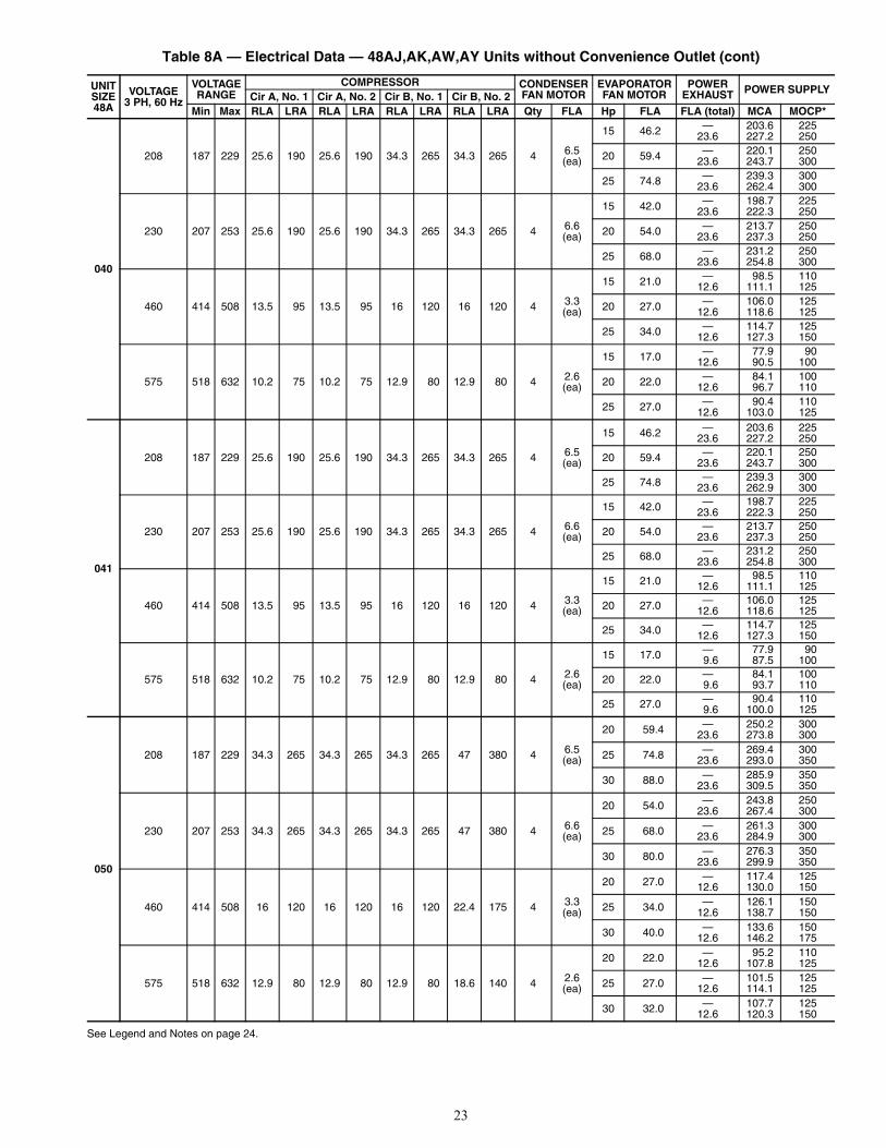
Table 8A — Electrical Data — 48AJ,AK,AW,AY Units without Convenience Outlet (cont)
See Legend and Notes on page 24.
UNITSIZE48A
VOLTAGE3 PH, 60 Hz
VOLTAGERANGE
COMPRESSOR CONDENSERFAN MOTOR
EVAPORATORFAN MOTOR
POWEREXHAUST POWER SUPPLY
Cir A, No. 1 Cir A, No. 2 Cir B, No. 1 Cir B, No. 2Min Max RLA LRA RLA LRA RLA LRA RLA LRA Qty FLA Hp FLA FLA (total) MCA MOCP*
040
208 187 229 25.6 190 25.6 190 34.3 265 34.3 265 4 6.5(ea)
15 46.2 — 203.6 22523.6 227.2 250
20 59.4 — 220.1 25023.6 243.7 300
25 74.8 — 239.3 30023.6 262.4 300
230 207 253 25.6 190 25.6 190 34.3 265 34.3 265 4 6.6(ea)
15 42.0 — 198.7 22523.6 222.3 250
20 54.0 — 213.7 25023.6 237.3 250
25 68.0 — 231.2 25023.6 254.8 300
460 414 508 13.5 95 13.5 95 16 120 16 120 4 3.3(ea)
15 21.0 — 98.5 11012.6 111.1 125
20 27.0 — 106.0 12512.6 118.6 125
25 34.0 — 114.7 12512.6 127.3 150
575 518 632 10.2 75 10.2 75 12.9 80 12.9 80 4 2.6(ea)
15 17.0 — 77.9 9012.6 90.5 100
20 22.0 — 84.1 10012.6 96.7 110
25 27.0 — 90.4 11012.6 103.0 125
041
208 187 229 25.6 190 25.6 190 34.3 265 34.3 265 4 6.5(ea)
15 46.2 — 203.6 22523.6 227.2 250
20 59.4 — 220.1 25023.6 243.7 300
25 74.8 — 239.3 30023.6 262.9 300
230 207 253 25.6 190 25.6 190 34.3 265 34.3 265 4 6.6(ea)
15 42.0 — 198.7 22523.6 222.3 250
20 54.0 — 213.7 25023.6 237.3 250
25 68.0 — 231.2 25023.6 254.8 300
460 414 508 13.5 95 13.5 95 16 120 16 120 4 3.3(ea)
15 21.0 — 98.5 11012.6 111.1 125
20 27.0 — 106.0 12512.6 118.6 125
25 34.0 — 114.7 12512.6 127.3 150
575 518 632 10.2 75 10.2 75 12.9 80 12.9 80 4 2.6(ea)
15 17.0 — 77.9 909.6 87.5 100
20 22.0 — 84.1 1009.6 93.7 110
25 27.0 — 90.4 1109.6 100.0 125
050
208 187 229 34.3 265 34.3 265 34.3 265 47 380 4 6.5(ea)
20 59.4 — 250.2 30023.6 273.8 300
25 74.8 — 269.4 30023.6 293.0 350
30 88.0 — 285.9 35023.6 309.5 350
230 207 253 34.3 265 34.3 265 34.3 265 47 380 4 6.6(ea)
20 54.0 — 243.8 25023.6 267.4 300
25 68.0 — 261.3 30023.6 284.9 300
30 80.0 — 276.3 35023.6 299.9 350
460 414 508 16 120 16 120 16 120 22.4 175 4 3.3(ea)
20 27.0 — 117.4 12512.6 130.0 150
25 34.0 — 126.1 15012.6 138.7 150
30 40.0 — 133.6 15012.6 146.2 175
575 518 632 12.9 80 12.9 80 12.9 80 18.6 140 4 2.6(ea)
20 22.0 — 95.2 11012.6 107.8 125
25 27.0 — 101.5 12512.6 114.1 125
30 32.0 — 107.7 12512.6 120.3 150
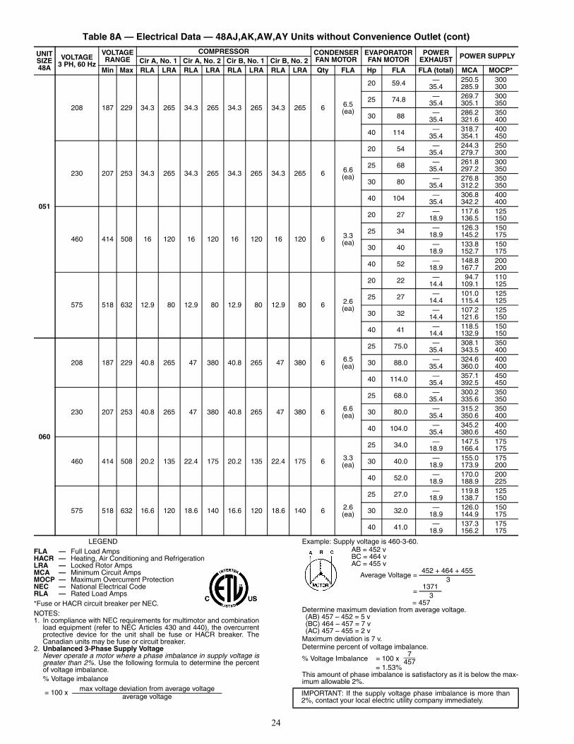
24
Table 8A — Electrical Data — 48AJ,AK,AW,AY Units without Convenience Outlet (cont)
LEGEND
*Fuse or HACR circuit breaker per NEC.NOTES:1. In compliance with NEC requirements for multimotor and combination
load equipment (refer to NEC Articles 430 and 440), the overcurrentprotective device for the unit shall be fuse or HACR breaker. TheCanadian units may be fuse or circuit breaker.
2. Unbalanced 3-Phase Supply VoltageNever operate a motor where a phase imbalance in supply voltage isgreater than 2%. Use the following formula to determine the percentof voltage imbalance.% Voltage imbalance
Example: Supply voltage is 460-3-60.AB = 452 vBC = 464 vAC = 455 v
= 457Determine maximum deviation from average voltage.(AB) 457 – 452 = 5 v(BC) 464 – 457 = 7 v (AC) 457 – 455 = 2 v
Maximum deviation is 7 v.Determine percent of voltage imbalance.
% Voltage Imbalance = 100 x = 1.53%
This amount of phase imbalance is satisfactory as it is below the max-imum allowable 2%.
UNITSIZE48A
VOLTAGE3 PH, 60 Hz
VOLTAGERANGE
COMPRESSOR CONDENSERFAN MOTOR
EVAPORATORFAN MOTOR
POWEREXHAUST POWER SUPPLY
Cir A, No. 1 Cir A, No. 2 Cir B, No. 1 Cir B, No. 2Min Max RLA LRA RLA LRA RLA LRA RLA LRA Qty FLA Hp FLA FLA (total) MCA MOCP*
051
208 187 229 34.3 265 34.3 265 34.3 265 34.3 265 6 6.5(ea)
20 59.4 — 250.5 30035.4 285.9 300
25 74.8 — 269.7 30035.4 305.1 350
30 88 — 286.2 35035.4 321.6 400
40 114 — 318.7 40035.4 354.1 450
230 207 253 34.3 265 34.3 265 34.3 265 34.3 265 6 6.6(ea)
20 54 — 244.3 25035.4 279.7 300
25 68 — 261.8 30035.4 297.2 350
30 80 — 276.8 35035.4 312.2 350
40 104 — 306.8 40035.4 342.2 400
460 414 508 16 120 16 120 16 120 16 120 6 3.3(ea)
20 27 — 117.6 12518.9 136.5 150
25 34 — 126.3 15018.9 145.2 175
30 40 — 133.8 15018.9 152.7 175
40 52 — 148.8 20018.9 167.7 200
575 518 632 12.9 80 12.9 80 12.9 80 12.9 80 6 2.6(ea)
20 22 — 94.7 11014.4 109.1 125
25 27 — 101.0 12514.4 115.4 125
30 32 — 107.2 12514.4 121.6 150
40 41 — 118.5 15014.4 132.9 150
060
208 187 229 40.8 265 47 380 40.8 265 47 380 6 6.5(ea)
25 75.0 — 308.1 35035.4 343.5 400
30 88.0 — 324.6 40035.4 360.0 400
40 114.0 — 357.1 45035.4 392.5 450
230 207 253 40.8 265 47 380 40.8 265 47 380 6 6.6(ea)
25 68.0 — 300.2 35035.4 335.6 350
30 80.0 — 315.2 35035.4 350.6 400
40 104.0 — 345.2 40035.4 380.6 450
460 414 508 20.2 135 22.4 175 20.2 135 22.4 175 6 3.3(ea)
25 34.0 — 147.5 17518.9 166.4 175
30 40.0 — 155.0 17518.9 173.9 200
40 52.0 — 170.0 20018.9 188.9 225
575 518 632 16.6 120 18.6 140 16.6 120 18.6 140 6 2.6(ea)
25 27.0 — 119.8 12518.9 138.7 150
30 32.0 — 126.0 15018.9 144.9 175
40 41.0 — 137.3 17518.9 156.2 175
FLA — Full Load AmpsHACR — Heating, Air Conditioning and RefrigerationLRA — Locked Rotor AmpsMCA — Minimum Circuit AmpsMOCP — Maximum Overcurrent ProtectionNEC — National Electrical CodeRLA — Rated Load Amps
= 100 x max voltage deviation from average voltageaverage voltage
Average Voltage =452 + 464 + 455
3
=1371
3
IMPORTANT: If the supply voltage phase imbalance is more than2%, contact your local electric utility company immediately.
7457
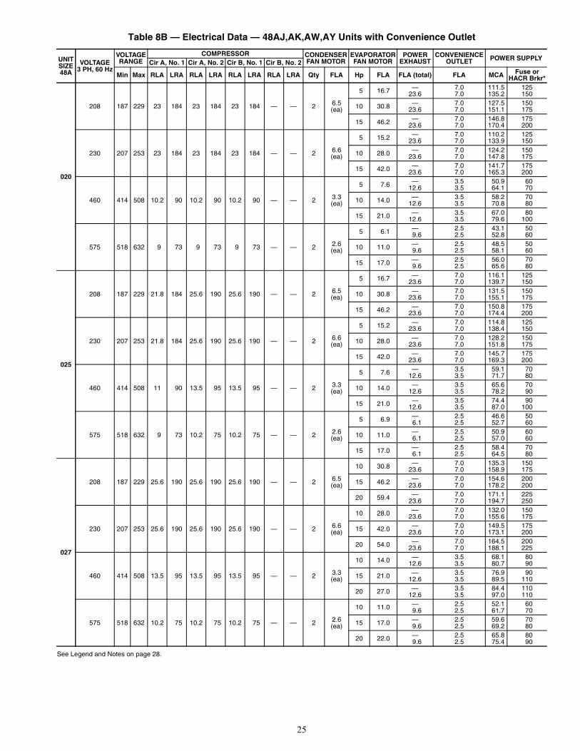
25
Table 8B — Electrical Data — 48AJ,AK,AW,AY Units with Convenience Outlet
See Legend and Notes on page 28.
UNITSIZE48A
VOLTAGE3 PH, 60 Hz
VOLTAGERANGE
COMPRESSOR CONDENSERFAN MOTOR
EVAPORATORFAN MOTOR
POWEREXHAUST
CONVENIENCEOUTLET POWER SUPPLY
Cir A, No. 1 Cir A, No. 2 Cir B, No. 1 Cir B, No. 2
Min Max RLA LRA RLA LRA RLA LRA RLA LRA Qty FLA Hp FLA FLA (total) FLA MCA Fuse orHACR Brkr*
020
208 187 229 23 184 23 184 23 184 — — 2 6.5(ea)
5 16.7 — 7.0 111.5 12523.6 7.0 135.2 150
10 30.8 — 7.0 127.5 15023.6 7.0 151.1 175
15 46.2 — 7.0 146.8 17523.6 7.0 170.4 200
230 207 253 23 184 23 184 23 184 — — 2 6.6(ea)
5 15.2 — 7.0 110.2 12523.6 7.0 133.9 150
10 28.0 — 7.0 124.2 15023.6 7.0 147.8 175
15 42.0 — 7.0 141.7 17523.6 7.0 165.3 200
460 414 508 10.2 90 10.2 90 10.2 90 — — 2 3.3(ea)
5 7.6 — 3.5 50.9 6012.6 3.5 64.1 70
10 14.0 — 3.5 58.2 7012.6 3.5 70.8 80
15 21.0 — 3.5 67.0 8012.6 3.5 79.6 100
575 518 632 9 73 9 73 9 73 — — 2 2.6(ea)
5 6.1 — 2.5 43.1 509.6 2.5 52.8 60
10 11.0 — 2.5 48.5 509.6 2.5 58.1 60
15 17.0 — 2.5 56.0 709.6 2.5 65.6 80
025
208 187 229 21.8 184 25.6 190 25.6 190 — — 2 6.5(ea)
5 16.7 — 7.0 116.1 12523.6 7.0 139.7 150
10 30.8 — 7.0 131.5 15023.6 7.0 155.1 175
15 46.2 — 7.0 150.8 17523.6 7.0 174.4 200
230 207 253 21.8 184 25.6 190 25.6 190 — — 2 6.6(ea)
5 15.2 — 7.0 114.8 12523.6 7.0 138.4 150
10 28.0 — 7.0 128.2 15023.6 7.0 151.8 175
15 42.0 — 7.0 145.7 17523.6 7.0 169.3 200
460 414 508 11 90 13.5 95 13.5 95 — — 2 3.3(ea)
5 7.6 — 3.5 59.1 7012.6 3.5 71.7 80
10 14.0 — 3.5 65.6 7012.6 3.5 78.2 90
15 21.0 — 3.5 74.4 9012.6 3.5 87.0 100
575 518 632 9 73 10.2 75 10.2 75 — — 2 2.6(ea)
5 6.9 — 2.5 46.6 506.1 2.5 52.7 60
10 11.0 — 2.5 50.9 606.1 2.5 57.0 60
15 17.0 — 2.5 58.4 706.1 2.5 64.5 80
027
208 187 229 25.6 190 25.6 190 25.6 190 — — 2 6.5(ea)
10 30.8 — 7.0 135.3 150 23.6 7.0 158.9 175
15 46.2 — 7.0 154.6 20023.6 7.0 178.2 200
20 59.4 — 7.0 171.1 22523.6 7.0 194.7 250
230 207 253 25.6 190 25.6 190 25.6 190 — — 2 6.6(ea)
10 28.0 — 7.0 132.0 15023.6 7.0 155.6 175
15 42.0 — 7.0 149.5 17523.6 7.0 173.1 200
20 54.0 — 7.0 164.5 20023.6 7.0 188.1 225
460 414 508 13.5 95 13.5 95 13.5 95 — — 2 3.3(ea)
10 14.0 — 3.5 68.1 8012.6 3.5 80.7 90
15 21.0 — 3.5 76.9 9012.6 3.5 89.5 110
20 27.0 — 3.5 84.4 11012.6 3.5 97.0 110
575 518 632 10.2 75 10.2 75 10.2 75 — — 2 2.6(ea)
10 11.0 — 2.5 52.1 609.6 2.5 61.7 70
15 17.0 — 2.5 59.6 709.6 2.5 69.2 80
20 22.0 — 2.5 65.8 809.6 2.5 75.4 90
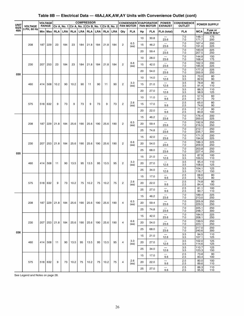
26
Table 8B — Electrical Data — 48AJ,AK,AW,AY Units with Convenience Outlet (cont)
See Legend and Notes on page 28.
UNITSIZE48A
VOLTAGE3 PH, 60 Hz
VOLTAGERANGE
COMPRESSOR CONDENSERFAN MOTOR
EVAPORATORFAN MOTOR
POWEREXHAUST
CONVENIENCEOUTLET POWER SUPPLY
Cir A, No. 1 Cir A, No. 2 Cir B, No. 1 Cir B, No. 2
Min Max RLA LRA RLA LRA RLA LRA RLA LRA Qty FLA Hp FLA FLA (total) FLA MCA Fuse orHACR Brkr*
030
208 187 229 23 184 23 184 21.8 184 21.8 184 2 6.5(ea)
10 30.8 — 7.0 148.1 17523.6 7.0 171.7 200
15 46.2 — 7.0 167.4 20023.6 7.0 191.0 225
20 59.4 — 7.0 183.9 22523.6 7.0 207.5 250
230 207 253 23 184 23 184 21.8 184 21.8 184 2 6.6(ea)
10 28.0 — 7.0 144.8 15023.6 7.0 168.4 175
15 42.0 — 7.0 162.3 20023.6 7.0 185.9 225
20 54.0 — 7.0 177.3 22523.6 7.0 200.9 250
460 414 508 10.2 90 10.2 90 11 90 11 90 2 3.3(ea)
10 14.0 — 3.5 70.0 8012.6 3.5 82.6 90
15 21.0 — 3.5 78.8 9012.6 3.5 91.4 110
20 27.0 — 3.5 86.3 11012.6 3.5 98.9 125
575 518 632 9 73 9 73 9 73 9 73 2 2.6(ea)
10 11.0 — 2.5 57.5 609.6 2.5 67.1 70
15 17.0 — 2.5 65.0 809.6 2.5 74.6 90
20 22.0 — 2.5 71.2 909.6 2.5 80.8 100
035
208 187 229 21.8 184 25.6 190 25.6 190 25.6 190 2 6.5(ea)
15 46.2 — 7.0 176.4 20023.6 7.0 200.0 225
20 59.4 — 7.0 192.9 25023.6 7.0 216.5 250
25 74.8 — 7.0 212.1 25023.6 7.0 235.7 300
230 207 253 21.8 184 25.6 190 25.6 190 25.6 190 2 6.6(ea)
15 42.0 — 7.0 171.3 20023.6 7.0 194.9 225
20 54.0 — 7.0 186.3 22523.6 7.0 209.9 250
25 68.0 — 7.0 203.8 25023.6 7.0 227.4 250
460 414 508 11 90 13.5 95 13.5 95 13.5 95 2 3.3(ea)
15 21.0 — 3.5 87.9 10012.6 3.5 100.5 110
20 27.0 — 3.5 95.4 11012.6 3.5 108.0 125
25 34.0 — 3.5 104.1 12512.6 3.5 116.7 150
575 518 632 9 73 10.2 75 10.2 75 10.2 75 2 2.6(ea)
15 17.0 — 2.5 68.6 809.6 2.5 78.2 90
20 22.0 — 2.5 74.8 909.6 2.5 84.4 100
25 27.0 — 2.5 81.1 1009.6 2.5 90.7 110
036
208 187 229 21.8 184 25.6 190 25.6 190 25.6 190 4 6.5(ea)
15 46.2 — 7.0 189.4 22523.6 7.0 213.0 250
20 59.4 — 7.0 205.9 25023.6 7.0 229.5 250
25 74.8 — 7.0 225.1 25023.6 7.0 248.7 300
230 207 253 21.8 184 25.6 190 25.6 190 25.6 190 4 6.6(ea)
15 42.0 — 7.0 184.5 22523.6 7.0 208.1 250
20 54.0 — 7.0 199.5 25023.6 7.0 223.1 250
25 68.0 — 7.0 217.0 25023.6 7.0 240.6 300
460 414 508 11 90 13.5 95 13.5 95 13.5 95 4 3.3(ea)
15 21.0 — 3.5 94.5 11012.6 3.5 107.1 125
20 27.0 — 3.5 102.0 12512.6 3.5 114.6 125
25 34.0 — 3.5 110.7 12512.6 3.5 123.3 150
575 518 632 9 73 10.2 75 10.2 75 10.2 75 4 2.6(ea)
15 17.0 — 2.5 73.8 909.6 2.5 83.4 100
20 22.0 — 2.5 80.0 1009.6 2.5 89.6 110
25 27.0 — 2.5 86.3 1109.6 2.5 95.9 110
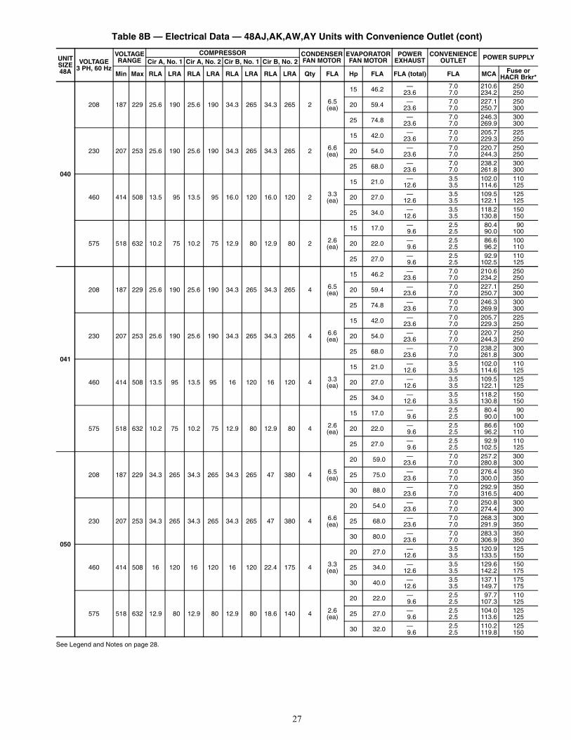
27
Table 8B — Electrical Data — 48AJ,AK,AW,AY Units with Convenience Outlet (cont)
See Legend and Notes on page 28.
UNITSIZE48A
VOLTAGE3 PH, 60 Hz
VOLTAGERANGE
COMPRESSOR CONDENSERFAN MOTOR
EVAPORATORFAN MOTOR
POWEREXHAUST
CONVENIENCEOUTLET POWER SUPPLY
Cir A, No. 1 Cir A, No. 2 Cir B, No. 1 Cir B, No. 2
Min Max RLA LRA RLA LRA RLA LRA RLA LRA Qty FLA Hp FLA FLA (total) FLA MCA Fuse orHACR Brkr*
040
208 187 229 25.6 190 25.6 190 34.3 265 34.3 265 2 6.5(ea)
15 46.2 — 7.0 210.6 25023.6 7.0 234.2 250
20 59.4 — 7.0 227.1 25023.6 7.0 250.7 300
25 74.8 — 7.0 246.3 30023.6 7.0 269.9 300
230 207 253 25.6 190 25.6 190 34.3 265 34.3 265 2 6.6(ea)
15 42.0 — 7.0 205.7 22523.6 7.0 229.3 250
20 54.0 — 7.0 220.7 25023.6 7.0 244.3 250
25 68.0 — 7.0 238.2 30023.6 7.0 261.8 300
460 414 508 13.5 95 13.5 95 16.0 120 16.0 120 2 3.3(ea)
15 21.0 — 3.5 102.0 11012.6 3.5 114.6 125
20 27.0 — 3.5 109.5 12512.6 3.5 122.1 125
25 34.0 — 3.5 118.2 15012.6 3.5 130.8 150
575 518 632 10.2 75 10.2 75 12.9 80 12.9 80 2 2.6(ea)
15 17.0 — 2.5 80.4 909.6 2.5 90.0 100
20 22.0 — 2.5 86.6 1009.6 2.5 96.2 110
25 27.0 — 2.5 92.9 1109.6 2.5 102.5 125
041
208 187 229 25.6 190 25.6 190 34.3 265 34.3 265 4 6.5(ea)
15 46.2 — 7.0 210.6 25023.6 7.0 234.2 250
20 59.4 — 7.0 227.1 25023.6 7.0 250.7 300
25 74.8 — 7.0 246.3 30023.6 7.0 269.9 300
230 207 253 25.6 190 25.6 190 34.3 265 34.3 265 4 6.6(ea)
15 42.0 — 7.0 205.7 22523.6 7.0 229.3 250
20 54.0 — 7.0 220.7 25023.6 7.0 244.3 250
25 68.0 — 7.0 238.2 30023.6 7.0 261.8 300
460 414 508 13.5 95 13.5 95 16 120 16 120 4 3.3(ea)
15 21.0 — 3.5 102.0 11012.6 3.5 114.6 125
20 27.0 — 3.5 109.5 12512.6 3.5 122.1 125
25 34.0 — 3.5 118.2 15012.6 3.5 130.8 150
575 518 632 10.2 75 10.2 75 12.9 80 12.9 80 4 2.6(ea)
15 17.0 — 2.5 80.4 909.6 2.5 90.0 100
20 22.0 — 2.5 86.6 1009.6 2.5 96.2 110
25 27.0 — 2.5 92.9 1109.6 2.5 102.5 125
050
208 187 229 34.3 265 34.3 265 34.3 265 47 380 4 6.5(ea)
20 59.0 — 7.0 257.2 30023.6 7.0 280.8 300
25 75.0 — 7.0 276.4 35023.6 7.0 300.0 350
30 88.0 — 7.0 292.9 35023.6 7.0 316.5 400
230 207 253 34.3 265 34.3 265 34.3 265 47 380 4 6.6(ea)
20 54.0 — 7.0 250.8 30023.6 7.0 274.4 300
25 68.0 — 7.0 268.3 30023.6 7.0 291.9 350
30 80.0 — 7.0 283.3 35023.6 7.0 306.9 350
460 414 508 16 120 16 120 16 120 22.4 175 4 3.3(ea)
20 27.0 — 3.5 120.9 12512.6 3.5 133.5 150
25 34.0 — 3.5 129.6 15012.6 3.5 142.2 175
30 40.0 — 3.5 137.1 17512.6 3.5 149.7 175
575 518 632 12.9 80 12.9 80 12.9 80 18.6 140 4 2.6(ea)
20 22.0 — 2.5 97.7 1109.6 2.5 107.3 125
25 27.0 — 2.5 104.0 1259.6 2.5 113.6 125
30 32.0 — 2.5 110.2 1259.6 2.5 119.8 150
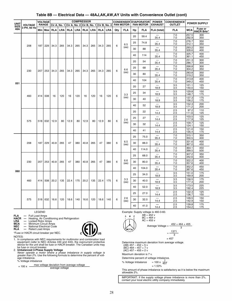
28
Table 8B — Electrical Data — 48AJ,AK,AW,AY Units with Convenience Outlet (cont)
LEGEND
*Fuse or HACR circuit breaker per NEC.NOTES:1. In compliance with NEC requirements for multimotor and combination load
equipment (refer to NEC Articles 430 and 440), the overcurrent protectivedevice for the unit shall be fuse or HACR breaker. The Canadian units maybe fuse or circuit breaker.
2. Unbalanced 3-Phase Supply VoltageNever operate a motor where a phase imbalance in supply voltage isgreater than 2%. Use the following formula to determine the percent of volt-age imbalance.% Voltage imbalance
Example: Supply voltage is 460-3-60.AB = 452 vBC = 464 vAC = 455 v
= 457Determine maximum deviation from average voltage.(AB) 457 – 452 = 5 v(BC) 464 – 457 = 7 v (AC) 457 – 455 = 2 v
Maximum deviation is 7 v.Determine percent of voltage imbalance.
% Voltage Imbalance = 100 x = 1.53%
This amount of phase imbalance is satisfactory as it is below the maximumallowable 2%.
UNITSIZE48A
VOLTAGE3 PH, 60 Hz
VOLTAGERANGE
COMPRESSOR CONDENSERFAN MOTOR
EVAPORATORFAN MOTOR
POWEREXHAUST
CONVENIENCEOUTLET POWER SUPPLY
Cir A, No. 1 Cir A, No. 2 Cir B, No. 1 Cir B, No. 2
Min Max RLA LRA RLA LRA RLA LRA RLA LRA Qty FLA Hp FLA FLA (total) FLA MCA Fuse orHACR Brkr*
051
208 187 229 34.3 265 34.3 265 34.3 265 34.3 265 6 6.5(ea)
20 59.4 — 7.0 257.5 30035.4 7.0 292.9 350
25 74.8 — 7.0 276.7 35035.4 7.0 312.1 350
30 88 — 7.0 293.2 35035.4 7.0 328.6 400
40 114 — 7.0 325.7 40035.4 7.0 361.1 450
230 207 253 34.3 265 34.3 265 34.3 265 34.3 265 6 6.6(ea)
20 54 — 7.0 251.3 30035.4 7.0 286.7 300
25 68 — 7.0 268.8 30035.4 7.0 304.2 350
30 80 — 7.0 283.8 35035.4 7.0 319.2 350
40 104 — 7.0 313.8 40035.4 7.0 349.2 450
460 414 508 16 120 16 120 16 120 16 120 6 3.3(ea)
20 27 — 3.5 121.1 12518.9 3.5 140.0 150
25 34 — 3.5 129.8 15018.9 3.5 148.7 175
30 40 — 3.5 137.3 17518.9 3.5 156.2 175
40 52 — 3.5 152.3 20018.9 3.5 171.2 200
575 518 632 12.9 80 12.9 80 12.9 80 12.9 80 6 2.6(ea)
20 22 — 2.5 97.2 11014.4 2.5 111.6 125
25 27 — 2.5 103.5 12514.4 2.5 117.9 125
30 32 — 2.5 109.7 12514.4 2.5 124.1 150
40 41 — 2.5 121.0 15014.4 2.5 135.4 175
060
208 187 229 40.8 265 47 380 40.8 265 47 380 6 6.5(ea)
25 75.0 — 7.0 315.1 35035.4 7.0 350.5 400
30 88.0 — 7.0 331.6 40035.4 7.0 367.0 450
40 114.0 — 7.0 364.1 45035.4 7.0 399.5 500
230 207 253 40.8 265 47 380 40.8 265 47 380 6 6.6(ea)
25 68.0 — 7.0 307.2 35035.4 7.0 342.6 400
30 80.0 — 7.0 322.2 40035.4 7.0 357.6 400
40 104.0 — 7.0 352.2 45035.4 7.0 387.6 450
460 414 508 20.2 135 22.4 175 20.2 135 22.4 175 6 3.3(ea)
25 34.0 — 3.5 151.0 17518.9 3.5 169.9 200
30 40.0 — 3.5 158.5 17518.9 3.5 177.4 200
40 52.0 — 3.5 173.5 22518.9 3.5 192.4 225
575 518 632 16.6 120 18.6 140 16.6 120 18.6 140 6 2.6(ea)
25 27.0 — 2.5 122.3 12514.4 2.5 136.7 150
30 32.0 — 2.5 128.5 15014.4 2.5 142.9 150
40 41.0 — 2.5 139.8 17514.4 2.5 154.2 175
FLA — Full Load AmpsHACR — Heating, Air Conditioning and RefrigerationLRA — Locked Rotor AmpsMCA — Minimum Circuit AmpsNEC — National Electrical CodeRLA — Rated Load Amps
= 100 x max voltage deviation from average voltageaverage voltage
Average Voltage =452 + 464 + 455
3
=1371
3
IMPORTANT: If the supply voltage phase imbalance is more than 2%,contact your local electric utility company immediately.
7457
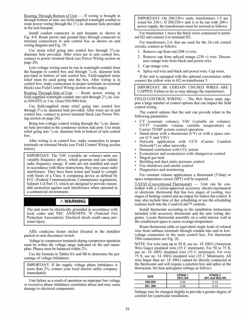
29
Routing Through Bottom of Unit — If wiring is brought inthrough bottom of unit, use field-supplied watertight conduit toroute power wiring through the 31/2-in. diameter hole providedin the unit basepan.
Install conduit connector in unit basepan as shown inFig. 4-9. Route power and ground lines through connector toterminal connections in unit control box as shown on unitwiring diagram and Fig. 19.
Use strain relief going into control box through 35/8-in.diameter hole provided. After wires are in unit control box,connect to power terminal block (see Power Wiring section onpage 20).
Low-voltage wiring must be run in watertight conduit fromthe basepan to control box and through 7/8-in. diameter holeprovided in bottom of unit control box. Field-supplied strainrelief must be used going into the box. After wiring is incontrol box, make connections to proper terminals on terminalblocks (see Field Control Wiring section on this page).Routing Through Side of Unit — Route power wiring infield-supplied watertight conduit into unit through 21/2-in. (siz-es 020-035) or 3-in. (sizes 036-060) hole.
Use field-supplied strain relief going into control boxthrough 35/8-in. diameter hole provided. After wires are in unitcontrol box, connect to power terminal block (see Power Wir-ing section on page 20).
Bring low-voltage control wiring through the 7/8-in. diame-ter hole provided in the condenser section side post. Use strainrelief going into 7/8-in. diameter hole in bottom of unit controlbox.
After wiring is in control box, make connection to properterminals on terminal blocks (see Field Control Wiring sectionbelow).
Affix crankcase heater sticker (located in the installerspacket) to unit disconnect switch.
Voltage to compressor terminals during compressor operationmust be within the voltage range indicated on the unit name-plate. Phases must be balanced within 2%.
Use the formula in Tables 8A and 8B to determine the per-centage of voltage imbalance.
Unit failure as a result of operation on improper line voltageor excessive phase imbalance constitutes abuse and may causedamage to electrical components.
For transformer 1 move the black wires connected to termi-nal H2 and connect it to terminal H3.
For transformers 2-4, that are used for the 24-volt controlcircuits, connect as follows:
1. Remove cap from red (208 v) wire.2. Remove cap from spliced orange (230 v) wire. Discon-
nect orange wire from black unit power wire.3. Cap orange wire.4. Splice red wire and black unit power wire. Cap wires.If the unit is equipped with the optional convenience outlet
connect the yellow wire to H2 on transformer 5.
FIELD CONTROL WIRING — The 48A Series units sup-port a large number of control options that can impact the fieldcontrol wiring.
The control options that the unit can provide relate to thefollowing parameters:• CV (constant volume), VAV (variable air volume),
VVT® (variable volume variable temperature) orCarrier TEMP system control operation.
• Stand-alone with a thermostat (CV) or with a space sen-sor (CV and VAV)
• Network application with CCN (Carrier ComfortNetwork®) or other networks
• Demand ventilation with CO2 sensor• Economizer and economizer with changeover control• Staged gas heat• Building and duct static pressure control• Fire shutdown and smoke control• Diagnostics and monitoring
For constant volume applications a thermostat (T-Stat) orspace temperature sensor (SPT) will be required.T-STAT (Conventional Thermostat) — Unit can be con-trolled with a Carrier-approved accessory electro-mechanicalor electronic thermostat that has two stages of cooling, twostages of heating control and an output for indoor fan control. Itmay also include time of day scheduling or use the schedulingroutines built into the ComfortLink™ controls.
Install thermostat according to the installation instructionsincluded with accessory thermostat and the unit wiring dia-grams. Locate thermostat assembly on a solid interior wall inthe conditioned space to sense average temperature.
Route thermostat cable or equivalent single leads of coloredwire from subbase terminals through conduit into unit to low-voltage connection in the main control box. For thermostatTB4 connections see Fig. 20.NOTE: For wire runs up to 50 ft, use no. 18 AWG (AmericanWire Gage) insulated wire (35 C minimum). For 50 to 75 ft,use no. 16 AWG insulated wire (35 C minimum). For over75 ft, use no. 14 AWG insulated wire (35 C Minimum). Allwire larger than no. 18 AWG cannot be directly connected atthe thermostat and will require a junction box and splice at thethermostat. Set heat anticipator settings as follows:
Settings may be changed slightly to provide a greater degree ofcomfort for a particular installation.
IMPORTANT: The VAV (variable air volume) units usevariable frequency drives, which generate and can radiateradio frequency energy. If units are not installed and usedin accordance with these instructions, they may cause radiointerference. They have been tested and found to complywith limits of a Class A computing device as defined byFCC (Federal Communications Commission) regulations,Subpart J of Part 15, which are designed to provide reason-able protection against such interference when operated ina commercial environment.
WARNING
The unit must be electrically grounded in accordance withlocal codes and NEC ANSI/NFPA 70 (National FireProtection Association). Electrical shock could cause per-sonal injury.
IMPORTANT: If the supply voltage phase imbalance ismore than 2%, contact your local electric utility companyimmediately.
IMPORTANT: On 208/230-v units, transformers 1-5 arewired for 230-v. If 208/230-v unit is to be run with 208-vpower supply, the transformers must be rewired as follows:
IMPORTANT: BE CERTAIN UNUSED WIRES ARECAPPED. Failure to do so may damage the transformers.
SIZE STAGE 1(W1) ON
STAGE 2(W1 and W2) ON
020-050 0.24 0.13051, 060 0.36 0.13
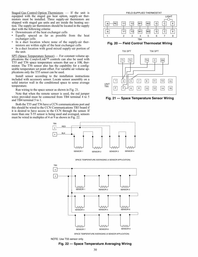
30
Staged Gas Control Option Thermistors — If the unit isequipped with the staged gas heat option, supply-air ther-mistors must be installed. Three supply-air thermistors areshipped with staged gas units and are inside the heating sec-tion. The supply-air thermistors should be located in the supplyduct with the following criteria:• Downstream of the heat exchanger cells• Equally spaced as far as possible from the heat
exchanger cells• In a duct location where none of the supply-air ther-
mistors are within sight of the heat exchanger cells• In a duct location with good mixed supply-air portion of
the unit.SPT (Space Temperature Sensor) — For constant volume ap-plications the ComfortLink™ controls can also be used withT55 and T56 space temperature sensors that use a 10K ther-mistor. The T56 sensor also has the capability for a config-urable temperature set point offset. For variable air volume ap-plications only the T55 sensor can be used.
Install sensor according to the installation instructionsincluded with accessory sensor. Locate sensor assembly on asolid interior wall in the conditioned space to sense averagetemperature.
Run wiring to the space sensor as shown in Fig. 21.Note that when the remote sensor is used, the red jumper
wires provided must be connected from TB4 terminal 4 to 5and TB4 terminal 5 to 1.
Both the T55 and T56 have a CCN communications port andthis should be wired to the CCN Communications TB3 board ifit is desired to have access to the CCN through the sensor. Ifmore than one T-55 sensor is being used and averaged, sensorsmust be wired in multiples of 4 or 9 as shown in Fig. 22.
T1 T2
1
2 4
3 5
6
7
8
9
10
11
12
13
14
15
16
TH C SN
T56 SPTT55 SPT
UNITTB5
TB4
Fig. 20 — Field Control Thermostat Wiring
Fig. 21 — Space Temperature Sensor Wiring
R Y1 Y2 W1 W2 G C X
R Y1 Y2 W1 W2 G C X
FIELD-SUPPLIED THERMOSTAT
LIGHT
RC
1 2 3 4 5 6 7 8a48-8243
a48-6854
3
4
RED
BLK
TB5
3
4
TB5
SENSOR 1 SENSOR 2 SENSOR 3 SENSOR 4
SENSOR 1 SENSOR 2 SENSOR 3
SENSOR 4 SENSOR 5 SENSOR 6
SENSOR 7 SENSOR 8 SENSOR 9
SPACE TEMPERATURE AVERAGING (4 SENSOR APPLICATION)
SPACE TEMPERATURE AVERAGING (9 SENSOR APPLICATION)
NOTE: Use T55 sensor only.
Fig. 22 — Space Temperature Averaging Wiring
a48-6855
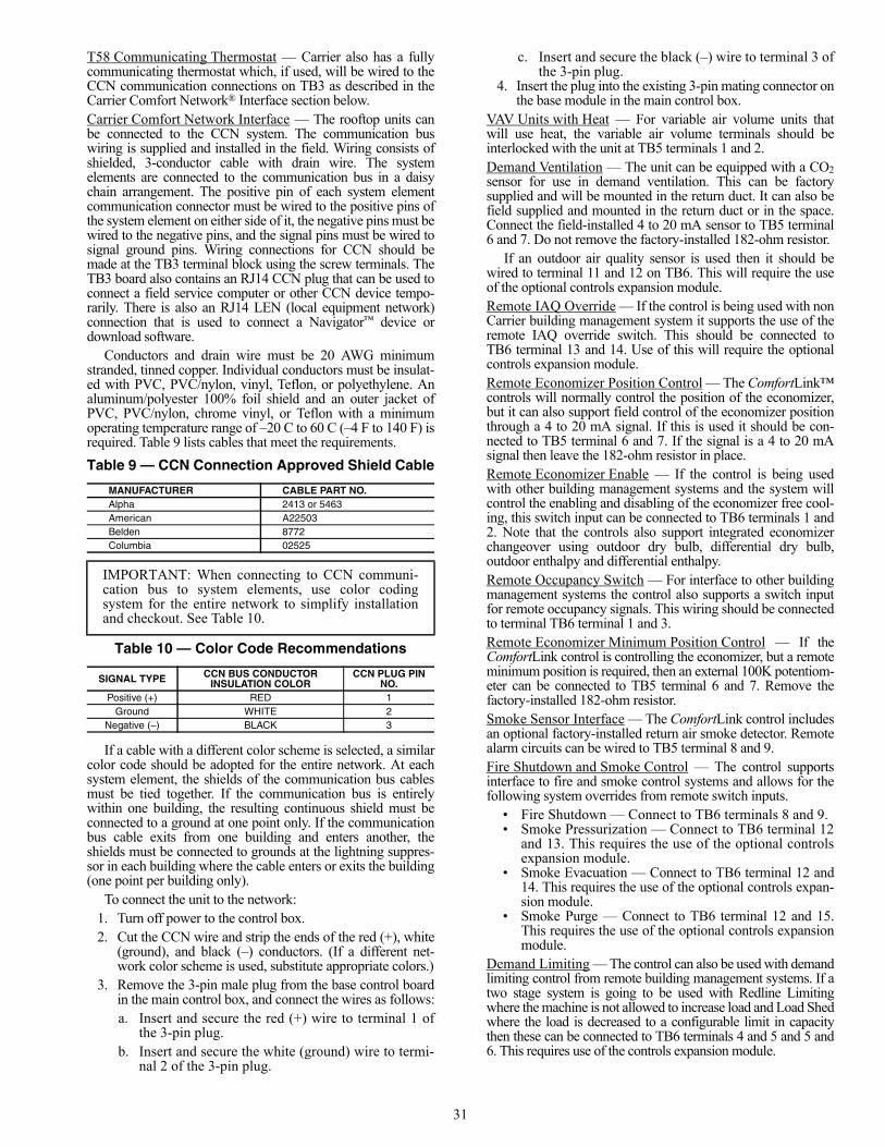
31
T58 Communicating Thermostat — Carrier also has a fullycommunicating thermostat which, if used, will be wired to theCCN communication connections on TB3 as described in theCarrier Comfort Network® Interface section below.Carrier Comfort Network Interface — The rooftop units canbe connected to the CCN system. The communication buswiring is supplied and installed in the field. Wiring consists ofshielded, 3-conductor cable with drain wire. The systemelements are connected to the communication bus in a daisychain arrangement. The positive pin of each system elementcommunication connector must be wired to the positive pins ofthe system element on either side of it, the negative pins must bewired to the negative pins, and the signal pins must be wired tosignal ground pins. Wiring connections for CCN should bemade at the TB3 terminal block using the screw terminals. TheTB3 board also contains an RJ14 CCN plug that can be used toconnect a field service computer or other CCN device tempo-rarily. There is also an RJ14 LEN (local equipment network)connection that is used to connect a Navigator™ device ordownload software.
Conductors and drain wire must be 20 AWG minimumstranded, tinned copper. Individual conductors must be insulat-ed with PVC, PVC/nylon, vinyl, Teflon, or polyethylene. Analuminum/polyester 100% foil shield and an outer jacket ofPVC, PVC/nylon, chrome vinyl, or Teflon with a minimumoperating temperature range of –20 C to 60 C (–4 F to 140 F) isrequired. Table 9 lists cables that meet the requirements.Table 9 — CCN Connection Approved Shield Cable
Table 10 — Color Code Recommendations
If a cable with a different color scheme is selected, a similarcolor code should be adopted for the entire network. At eachsystem element, the shields of the communication bus cablesmust be tied together. If the communication bus is entirelywithin one building, the resulting continuous shield must beconnected to a ground at one point only. If the communicationbus cable exits from one building and enters another, theshields must be connected to grounds at the lightning suppres-sor in each building where the cable enters or exits the building(one point per building only).
To connect the unit to the network:1. Turn off power to the control box.2. Cut the CCN wire and strip the ends of the red (+), white
(ground), and black (–) conductors. (If a different net-work color scheme is used, substitute appropriate colors.)
3. Remove the 3-pin male plug from the base control boardin the main control box, and connect the wires as follows:a. Insert and secure the red (+) wire to terminal 1 of
the 3-pin plug.b. Insert and secure the white (ground) wire to termi-
nal 2 of the 3-pin plug.
c. Insert and secure the black (–) wire to terminal 3 ofthe 3-pin plug.
4. Insert the plug into the existing 3-pin mating connector onthe base module in the main control box.
VAV Units with Heat — For variable air volume units thatwill use heat, the variable air volume terminals should beinterlocked with the unit at TB5 terminals 1 and 2.Demand Ventilation — The unit can be equipped with a CO2sensor for use in demand ventilation. This can be factorysupplied and will be mounted in the return duct. It can also befield supplied and mounted in the return duct or in the space.Connect the field-installed 4 to 20 mA sensor to TB5 terminal6 and 7. Do not remove the factory-installed 182-ohm resistor.
If an outdoor air quality sensor is used then it should bewired to terminal 11 and 12 on TB6. This will require the useof the optional controls expansion module.Remote IAQ Override — If the control is being used with nonCarrier building management system it supports the use of theremote IAQ override switch. This should be connected toTB6 terminal 13 and 14. Use of this will require the optionalcontrols expansion module.Remote Economizer Position Control — The ComfortLink™controls will normally control the position of the economizer,but it can also support field control of the economizer positionthrough a 4 to 20 mA signal. If this is used it should be con-nected to TB5 terminal 6 and 7. If the signal is a 4 to 20 mAsignal then leave the 182-ohm resistor in place.Remote Economizer Enable — If the control is being usedwith other building management systems and the system willcontrol the enabling and disabling of the economizer free cool-ing, this switch input can be connected to TB6 terminals 1 and2. Note that the controls also support integrated economizerchangeover using outdoor dry bulb, differential dry bulb,outdoor enthalpy and differential enthalpy.Remote Occupancy Switch — For interface to other buildingmanagement systems the control also supports a switch inputfor remote occupancy signals. This wiring should be connectedto terminal TB6 terminal 1 and 3.Remote Economizer Minimum Position Control — If theComfortLink control is controlling the economizer, but a remoteminimum position is required, then an external 100K potentiom-eter can be connected to TB5 terminal 6 and 7. Remove thefactory-installed 182-ohm resistor.Smoke Sensor Interface — The ComfortLink control includesan optional factory-installed return air smoke detector. Remotealarm circuits can be wired to TB5 terminal 8 and 9.Fire Shutdown and Smoke Control — The control supportsinterface to fire and smoke control systems and allows for thefollowing system overrides from remote switch inputs.
• Fire Shutdown — Connect to TB6 terminals 8 and 9.• Smoke Pressurization — Connect to TB6 terminal 12
and 13. This requires the use of the optional controlsexpansion module.
• Smoke Evacuation — Connect to TB6 terminal 12 and14. This requires the use of the optional controls expan-sion module.
• Smoke Purge — Connect to TB6 terminal 12 and 15.This requires the use of the optional controls expansionmodule.
Demand Limiting — The control can also be used with demandlimiting control from remote building management systems. If atwo stage system is going to be used with Redline Limitingwhere the machine is not allowed to increase load and Load Shedwhere the load is decreased to a configurable limit in capacitythen these can be connected to TB6 terminals 4 and 5 and 5 and6. This requires use of the controls expansion module.
MANUFACTURER CABLE PART NO.Alpha 2413 or 5463American A22503Belden 8772Columbia 02525
IMPORTANT: When connecting to CCN communi-cation bus to system elements, use color codingsystem for the entire network to simplify installationand checkout. See Table 10.
SIGNAL TYPE CCN BUS CONDUCTOR INSULATION COLOR
CCN PLUG PIN NO.
Positive (+) RED 1Ground WHITE 2
Negative (–) BLACK 3
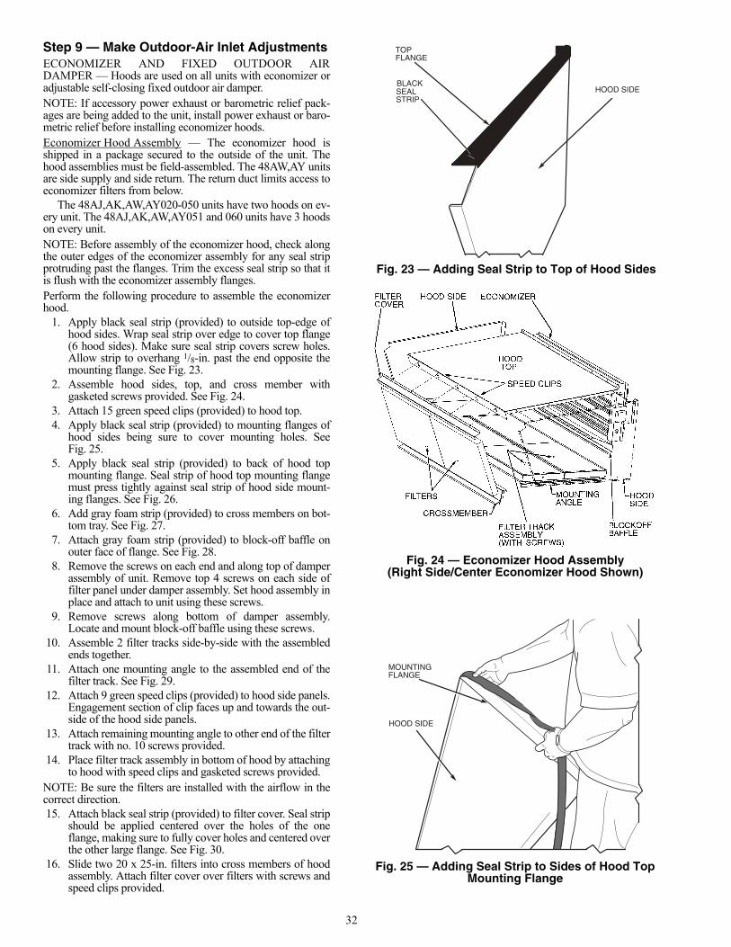
32
Step 9 — Make Outdoor-Air Inlet AdjustmentsECONOMIZER AND FIXED OUTDOOR AIRDAMPER — Hoods are used on all units with economizer oradjustable self-closing fixed outdoor air damper.NOTE: If accessory power exhaust or barometric relief pack-ages are being added to the unit, install power exhaust or baro-metric relief before installing economizer hoods.Economizer Hood Assembly — The economizer hood isshipped in a package secured to the outside of the unit. Thehood assemblies must be field-assembled. The 48AW,AY unitsare side supply and side return. The return duct limits access toeconomizer filters from below.
The 48AJ,AK,AW,AY020-050 units have two hoods on ev-ery unit. The 48AJ,AK,AW,AY051 and 060 units have 3 hoodson every unit.NOTE: Before assembly of the economizer hood, check alongthe outer edges of the economizer assembly for any seal stripprotruding past the flanges. Trim the excess seal strip so that itis flush with the economizer assembly flanges.Perform the following procedure to assemble the economizerhood.
1. Apply black seal strip (provided) to outside top-edge ofhood sides. Wrap seal strip over edge to cover top flange(6 hood sides). Make sure seal strip covers screw holes.Allow strip to overhang 1/8-in. past the end opposite themounting flange. See Fig. 23.
2. Assemble hood sides, top, and cross member withgasketed screws provided. See Fig. 24.
3. Attach 15 green speed clips (provided) to hood top.4. Apply black seal strip (provided) to mounting flanges of
hood sides being sure to cover mounting holes. SeeFig. 25.
5. Apply black seal strip (provided) to back of hood topmounting flange. Seal strip of hood top mounting flangemust press tightly against seal strip of hood side mount-ing flanges. See Fig. 26.
6. Add gray foam strip (provided) to cross members on bot-tom tray. See Fig. 27.
7. Attach gray foam strip (provided) to block-off baffle onouter face of flange. See Fig. 28.
8. Remove the screws on each end and along top of damperassembly of unit. Remove top 4 screws on each side offilter panel under damper assembly. Set hood assembly inplace and attach to unit using these screws.
9. Remove screws along bottom of damper assembly.Locate and mount block-off baffle using these screws.
10. Assemble 2 filter tracks side-by-side with the assembledends together.
11. Attach one mounting angle to the assembled end of thefilter track. See Fig. 29.
12. Attach 9 green speed clips (provided) to hood side panels.Engagement section of clip faces up and towards the out-side of the hood side panels.
13. Attach remaining mounting angle to other end of the filtertrack with no. 10 screws provided.
14. Place filter track assembly in bottom of hood by attachingto hood with speed clips and gasketed screws provided.
NOTE: Be sure the filters are installed with the airflow in thecorrect direction.15. Attach black seal strip (provided) to filter cover. Seal strip
should be applied centered over the holes of the oneflange, making sure to fully cover holes and centered overthe other large flange. See Fig. 30.
16. Slide two 20 x 25-in. filters into cross members of hoodassembly. Attach filter cover over filters with screws andspeed clips provided.
HOOD SIDE
TOPFLANGE
SEALSTRIP
BLACK
Fig. 23 — Adding Seal Strip to Top of Hood Sides
Fig. 24 — Economizer Hood Assembly(Right Side/Center Economizer Hood Shown)
HOOD SIDE
MOUNTINGFLANGE
Fig. 25 — Adding Seal Strip to Sides of Hood TopMounting Flange
a48-8498
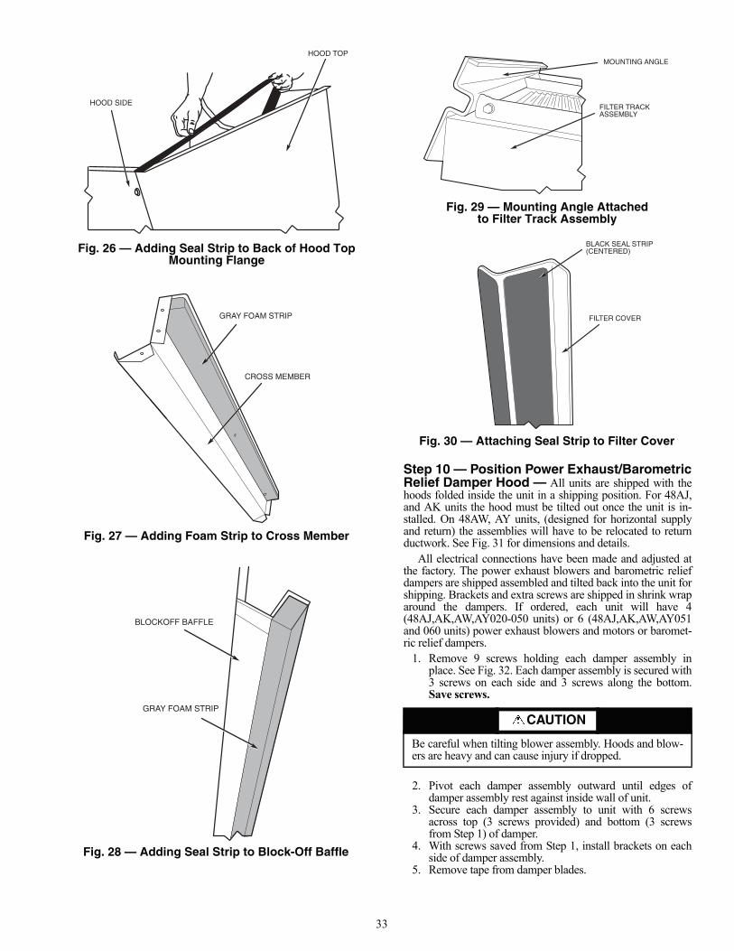
33
Step 10 — Position Power Exhaust/BarometricRelief Damper Hood — All units are shipped with thehoods folded inside the unit in a shipping position. For 48AJ,and AK units the hood must be tilted out once the unit is in-stalled. On 48AW, AY units, (designed for horizontal supplyand return) the assemblies will have to be relocated to returnductwork. See Fig. 31 for dimensions and details.
All electrical connections have been made and adjusted atthe factory. The power exhaust blowers and barometric reliefdampers are shipped assembled and tilted back into the unit forshipping. Brackets and extra screws are shipped in shrink wraparound the dampers. If ordered, each unit will have 4(48AJ,AK,AW,AY020-050 units) or 6 (48AJ,AK,AW,AY051and 060 units) power exhaust blowers and motors or baromet-ric relief dampers.
1. Remove 9 screws holding each damper assembly inplace. See Fig. 32. Each damper assembly is secured with3 screws on each side and 3 screws along the bottom.Save screws.
2. Pivot each damper assembly outward until edges ofdamper assembly rest against inside wall of unit.
3. Secure each damper assembly to unit with 6 screwsacross top (3 screws provided) and bottom (3 screwsfrom Step 1) of damper.
4. With screws saved from Step 1, install brackets on eachside of damper assembly.
5. Remove tape from damper blades.
CAUTION
Be careful when tilting blower assembly. Hoods and blow-ers are heavy and can cause injury if dropped.
MOUNTING ANGLE
FILTER TRACKASSEMBLY
Fig. 29 — Mounting Angle Attachedto Filter Track Assembly
a48-8499
BLACK SEAL STRIP(CENTERED)
FILTER COVER
Fig. 30 — Attaching Seal Strip to Filter Cover
48-1110
HOOD TOP
HOOD SIDE
CROSS MEMBER
GRAY FOAM STRIP
Fig. 26 — Adding Seal Strip to Back of Hood TopMounting Flange
Fig. 27 — Adding Foam Strip to Cross Member
48-1104
48-1105
BLOCKOFF BAFFLE
GRAY FOAM STRIP
Fig. 28 — Adding Seal Strip to Block-Off Baffle
a48-4328
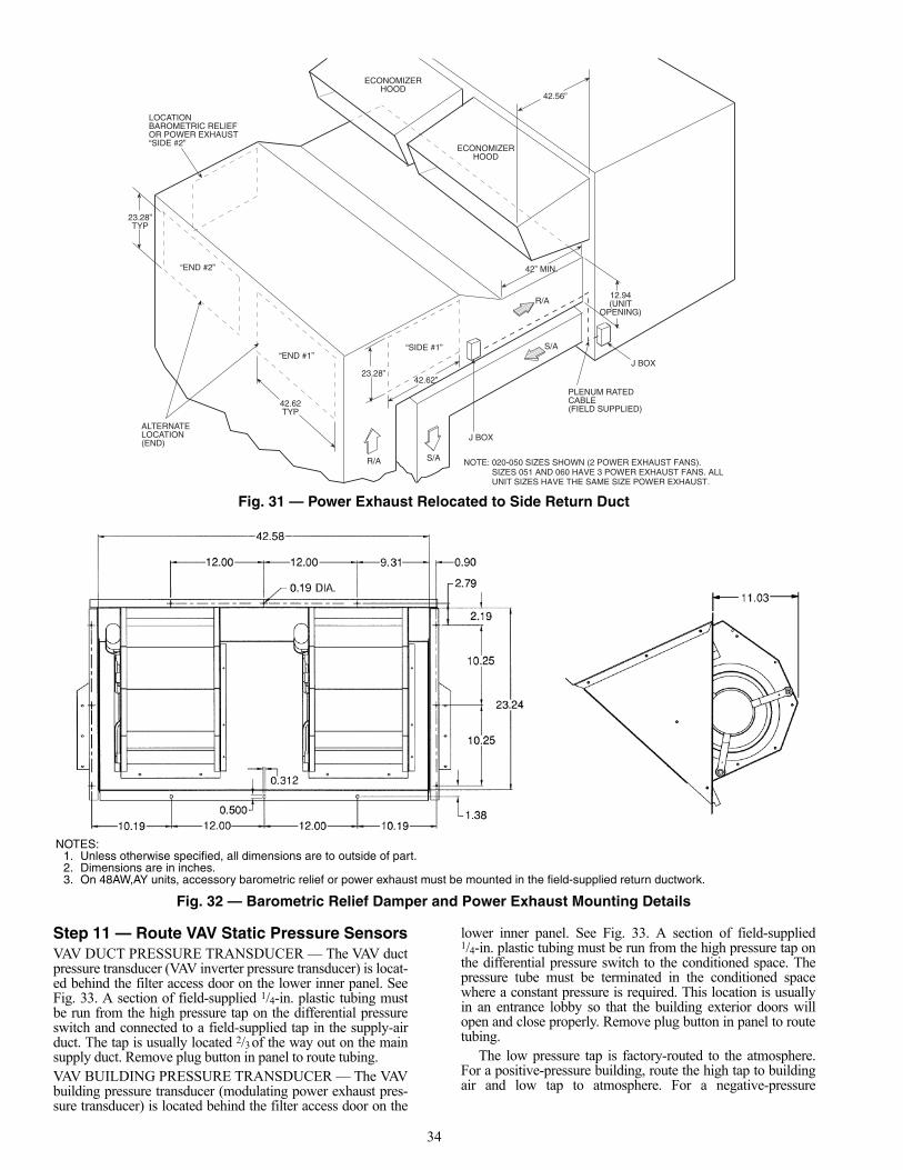
34
Step 11 — Route VAV Static Pressure SensorsVAV DUCT PRESSURE TRANSDUCER — The VAV ductpressure transducer (VAV inverter pressure transducer) is locat-ed behind the filter access door on the lower inner panel. SeeFig. 33. A section of field-supplied 1/4-in. plastic tubing mustbe run from the high pressure tap on the differential pressureswitch and connected to a field-supplied tap in the supply-airduct. The tap is usually located 2/3 of the way out on the mainsupply duct. Remove plug button in panel to route tubing.VAV BUILDING PRESSURE TRANSDUCER — The VAVbuilding pressure transducer (modulating power exhaust pres-sure transducer) is located behind the filter access door on the
lower inner panel. See Fig. 33. A section of field-supplied1/4-in. plastic tubing must be run from the high pressure tap onthe differential pressure switch to the conditioned space. Thepressure tube must be terminated in the conditioned spacewhere a constant pressure is required. This location is usuallyin an entrance lobby so that the building exterior doors willopen and close properly. Remove plug button in panel to routetubing.
The low pressure tap is factory-routed to the atmosphere.For a positive-pressure building, route the high tap to buildingair and low tap to atmosphere. For a negative-pressure
42.56”
42” MIN.
S/A
R/A
ECONOMIZERHOOD
ECONOMIZERHOOD
J BOX
PLENUM RATEDCABLE(FIELD SUPPLIED)
12.94(UNIT
OPENING)
NOTE: 020-050 SIZES SHOWN (2 POWER EXHAUST FANS). SIZES 051 AND 060 HAVE 3 POWER EXHAUST FANS. ALL UNIT SIZES HAVE THE SAME SIZE POWER EXHAUST.
“END #2”
“END #1”
ALTERNATELOCATION(END)
23.28”TYP
42.62TYP
LOCATIONBAROMETRIC RELIEFOR POWER EXHAUST“SIDE #2”
23.28”
“SIDE #1”
42.62”
J BOX
R/A S/A
Fig. 31 — Power Exhaust Relocated to Side Return Duct
a48-8244
NOTES:1. Unless otherwise specified, all dimensions are to outside of part.2. Dimensions are in inches.3. On 48AW,AY units, accessory barometric relief or power exhaust must be mounted in the field-supplied return ductwork.
Fig. 32 — Barometric Relief Damper and Power Exhaust Mounting Details
a48-3808
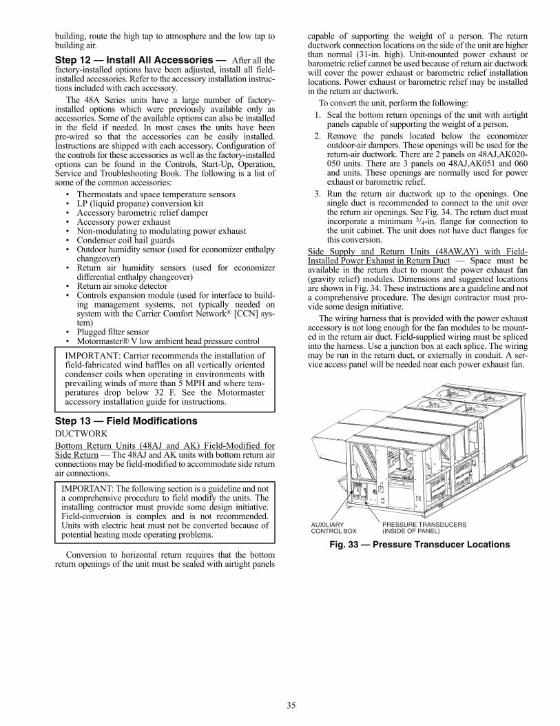
35
building, route the high tap to atmosphere and the low tap tobuilding air.
Step 12 — Install All Accessories — After all thefactory-installed options have been adjusted, install all field-installed accessories. Refer to the accessory installation instruc-tions included with each accessory.
The 48A Series units have a large number of factory-installed options which were previously available only asaccessories. Some of the available options can also be installedin the field if needed. In most cases the units have beenpre-wired so that the accessories can be easily installed.Instructions are shipped with each accessory. Configuration ofthe controls for these accessories as well as the factory-installedoptions can be found in the Controls, Start-Up, Operation,Service and Troubleshooting Book. The following is a list ofsome of the common accessories:
• Thermostats and space temperature sensors• LP (liquid propane) conversion kit• Accessory barometric relief damper• Accessory power exhaust• Non-modulating to modulating power exhaust• Condenser coil hail guards• Outdoor humidity sensor (used for economizer enthalpy
changeover)• Return air humidity sensors (used for economizer
differential enthalpy changeover)• Return air smoke detector• Controls expansion module (used for interface to build-
ing management systems, not typically needed onsystem with the Carrier Comfort Network® [CCN] sys-tem)
• Plugged filter sensor• Motormaster® V low ambient head pressure control
Step 13 — Field ModificationsDUCTWORKBottom Return Units (48AJ and AK) Field-Modified forSide Return — The 48AJ and AK units with bottom return airconnections may be field-modified to accommodate side returnair connections.
Conversion to horizontal return requires that the bottomreturn openings of the unit must be sealed with airtight panels
capable of supporting the weight of a person. The returnductwork connection locations on the side of the unit are higherthan normal (31-in. high). Unit-mounted power exhaust orbarometric relief cannot be used because of return air ductworkwill cover the power exhaust or barometric relief installationlocations. Power exhaust or barometric relief may be installedin the return air ductwork.
To convert the unit, perform the following:1. Seal the bottom return openings of the unit with airtight
panels capable of supporting the weight of a person.2. Remove the panels located below the economizer
outdoor-air dampers. These openings will be used for thereturn-air ductwork. There are 2 panels on 48AJ,AK020-050 units. There are 3 panels on 48AJ,AK051 and 060and units. These openings are normally used for powerexhaust or barometric relief.
3. Run the return air ductwork up to the openings. Onesingle duct is recommended to connect to the unit overthe return air openings. See Fig. 34. The return duct mustincorporate a minimum 3/4-in. flange for connection tothe unit cabinet. The unit does not have duct flanges forthis conversion.
Side Supply and Return Units (48AW,AY) with Field-Installed Power Exhaust in Return Duct — Space must beavailable in the return duct to mount the power exhaust fan(gravity relief) modules. Dimensions and suggested locationsare shown in Fig. 34. These instructions are a guideline and nota comprehensive procedure. The design contractor must pro-vide some design initiative.
The wiring harness that is provided with the power exhaustaccessory is not long enough for the fan modules to be mount-ed in the return air duct. Field-supplied wiring must be splicedinto the harness. Use a junction box at each splice. The wiringmay be run in the return duct, or externally in conduit. A ser-vice access panel will be needed near each power exhaust fan.
IMPORTANT: Carrier recommends the installation offield-fabricated wind baffles on all vertically orientedcondenser coils when operating in environments withprevailing winds of more than 5 MPH and where tem-peratures drop below 32 F. See the Motormasteraccessory installation guide for instructions.
IMPORTANT: The following section is a guideline and nota comprehensive procedure to field modify the units. Theinstalling contractor must provide some design initiative.Field-conversion is complex and is not recommended.Units with electric heat must not be converted because ofpotential heating mode operating problems.
AUXILIARYCONTROL BOX
PRESSURE TRANSDUCERS(INSIDE OF PANEL)
Fig. 33 — Pressure Transducer Locations
a48-6976
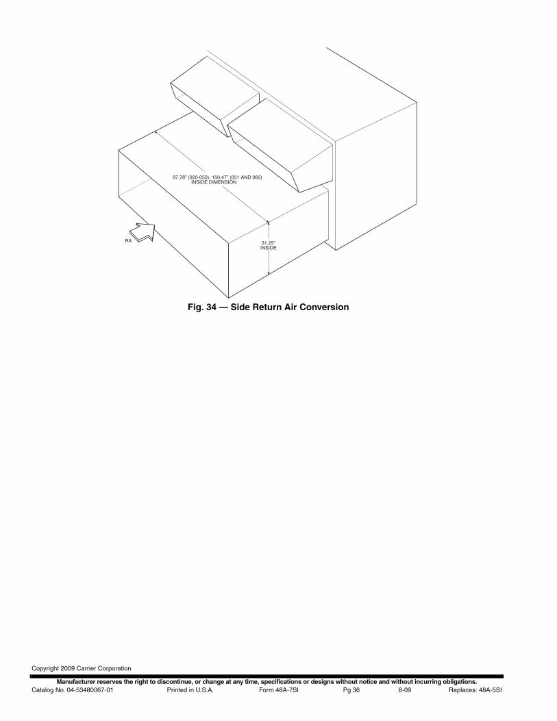
Manufacturer reserves the right to discontinue, or change at any time, specifications or designs without notice and without incurring obligations.Catalog No. 04-53480067-01 Printed in U.S.A. Form 48A-7SI Pg 36 8-09 Replaces: 48A-5SI
Copyright 2009 Carrier Corporation
31.25”INSIDE
RA
97.78” (020-050), 150.47” (051 AND 060)INSIDE DIMENSION
Fig. 34 — Side Return Air Conversion
a48-8245