Comfort 150 / 160 - minikon.si za podporo/Marantec... · the upper door lamella (see picture 7.1)....
30
1 => GND 2 => Impulz 3 => 24 V Tipka = 1-2
-
Upload
vuongtuyen -
Category
Documents
-
view
213 -
download
0
Transcript of Comfort 150 / 160 - minikon.si za podporo/Marantec... · the upper door lamella (see picture 7.1)....

Comfort 150 / 160Einbau- und BedienungsanleitungGaragentor-Antrieb
Installation and Operating InstructionsGarage Door Operator
D
GB
Bitte sorgfältig aufbewahren.Keep these instructions for later reference.
1 => GND2 => Impulz3 => 24 V
Tipka = 1-2
Mitja
Tipkano besedilo

English Page 34
• Grease the carriage bearers on all sides.• Push lever (A) forward and slide the carriage into the boom before moving lever (A) back to
normal.• Remove locking pin (B).
O4Screw wall bracket (A) onto the boom.O5
Please follow the installation and fitting instructions carefully toavoid wrong installation or damage to the door and door operator. Keep these instructions for later reference.
The following tools are required:Combination wrench SW 10Combination wrench SW 13Socket wrench SW 10Socket wrench SW 13Screwdriver, size 8Screwdriver, size 5Phillips screwdriver, size 2Phillips screwdriver, size 3
Masonry drill 10 mm dia.Masonry drill 6 mm dia.Metal drill 5 mm dia.Metal drill 7 mm dia.PliersHack sawElectric drillHammerFolding rule
Attention:Before drilling, cover over the motor with foil, film or cardboard. Drilling dust and chippings can lead to malfunctions.
O2
• Slide the boom into the motor housing.• Screw supplied centering screws (A) through the boom into the motor housing.• Screw on the 2 setscrews (B) tightly.
O3
Unpack the boom, motor housing and accessories ready for installation.O1

English Page 35
O7
O6 Up-and-over doors:• Screw wall bracket (A) with boom to the top door frame, lintel or ceiling, so that the upper
door edge lies approx. 10 mm below the horizontal downward boom edge - measured fromthe highest point of the opening course. (see picture 6 and 10).
• Put the motor unit on a trestle or another suitable object until it is fixed later on to theceiling.
• Join two door link brackets (B) to the door connector (C) and screw them with 4 screws tothe centre of the upper door edge (see picture 6). Drill bit Ø 5mm.
• Join door link (D) to the carriage (E) and door link brackets (B).• Use extended door link in case the min. distance of 165 mm cannot be kept due
to the given situation on building.
Remove door locks or put them out of operation.
Sectional doors:• Screw the wall bracket (A) with boom to the top door frame, lintel or ceiling, so that the
upper lamella of the door lies approx. 10 mm below the horizontal downward boomedge - measured from the highest point of the opening course (see pictures 7.1 and 10).
• Put the motor unit on a trestle or another suitable object until it is fixed later onto the ceiling.
• Join two door link brackets (B) to the door connector (C) and screw them with 4 screws tothe upper door lamella (see picture 7.1). Drill bit Ø 5mm.
• If necessary, the motor unit can be installed 200 mm off-centre.• For wooden sectional doors please use wood-screws Ø 5x35mm.
Drill bit Ø:3 mm.
• Screw two self-tapping screws (D) into the door connector until the points of the screwsare situated in front of the lamella.
• Join door link (E) with carriage (F) and door link brackets (B).• Use extended door link in case the min. distance of 165 mm cannot be kept due to the
given situation on building.
Remove the door locks or put them out of operation.Attention:For big and heavy sectional doors please use additionally door connector attachmentSpezial 111, Art.-No. 47 574 (see picture 7.2)(This is not part of the supply package).

English Page 36
Retractable up-and-over doors:Special 102 adapter arm, item no. 564 865, and Special 601 photocell, item no. 564 266, are required (not included in the supply package). Until the ceiling mounts are subsequently fitted, support the motor housing using a trestle or other suitable object. Before installing the operator, put the door locks out of operation. Screw wall bracket (A) with boom to the top of the door surround or lintel centrally abovethe door ensuring that the top edge of the door at its highest point of opening clears thebottom edge of the boom by at least 10 mm (see pt. 10).
Fitting the adapter arm:Screw support bracket (B) with 6 self-tapping screws to the centre of the top edge of thedoor leaf (5 mm dia. drill). The support bracket and boom meet centre to centre.
Slot adapter arm (C) into support bracket (B) and using two angle plates (D), screw to door cross strut (E).
Drill 5 mm dia. hole in the door cross strut (4x)Drill 7 mm dia. hole in the adapter arm (2x)
Angle plates (D) are screwed to the adapter arm using two M6 x 10 screws and hexagon nuts.
Open the door fully, connect carriage (F) and linking bar (G) to adapter arm (C) observing the given dimensions. By lowering the carriage and extending the linking bar, the door opening is enlarged. The linking bar may only be pulled out to the extent that the internally located pressure rollers (H) do not abut against check screws (I).
Close the door and check that the minimum distance of 165 mm has not been exceeded.
To ensure optimum operation of the operator and door, the door travel speed should be altered to 8 cm/s.See point 11 of the Installation Instructions.
O8
Bolt on 2 support straps (A) to the motor housing. Bend them according to site requirements and saw off the projecting lengths (see pt. 10).
Attach one support strap to the centre of the boom.
O9Suspend the motor housing with boom from the ceiling, making sure that the top edge of thedoor at its highest point of opening clears the bottom edge of the boom by 10 mm (see pts. 6, 7 and 8). Install the ceiling mounts as constructional features of the garage allow (note drill depth for wall plugs).
O10
English Page 37
Attention:Before opening the housing, always disconnect the operator from the mains!
Remove the motor cover's central fixing screw (A). Press all four locking hooks (B) inwards and pull the motor cover down and off.
Slide belt cover (C) approx. 5 mm in the direction of the arrow, press together at the bottom and pull away upwards.
Slip the drive belt first over the small lower motor pulley (D) and then over the large upper spindle pulley (E).
Do not use any sharp-edged tools.
Re-assemble in reverse sequence.
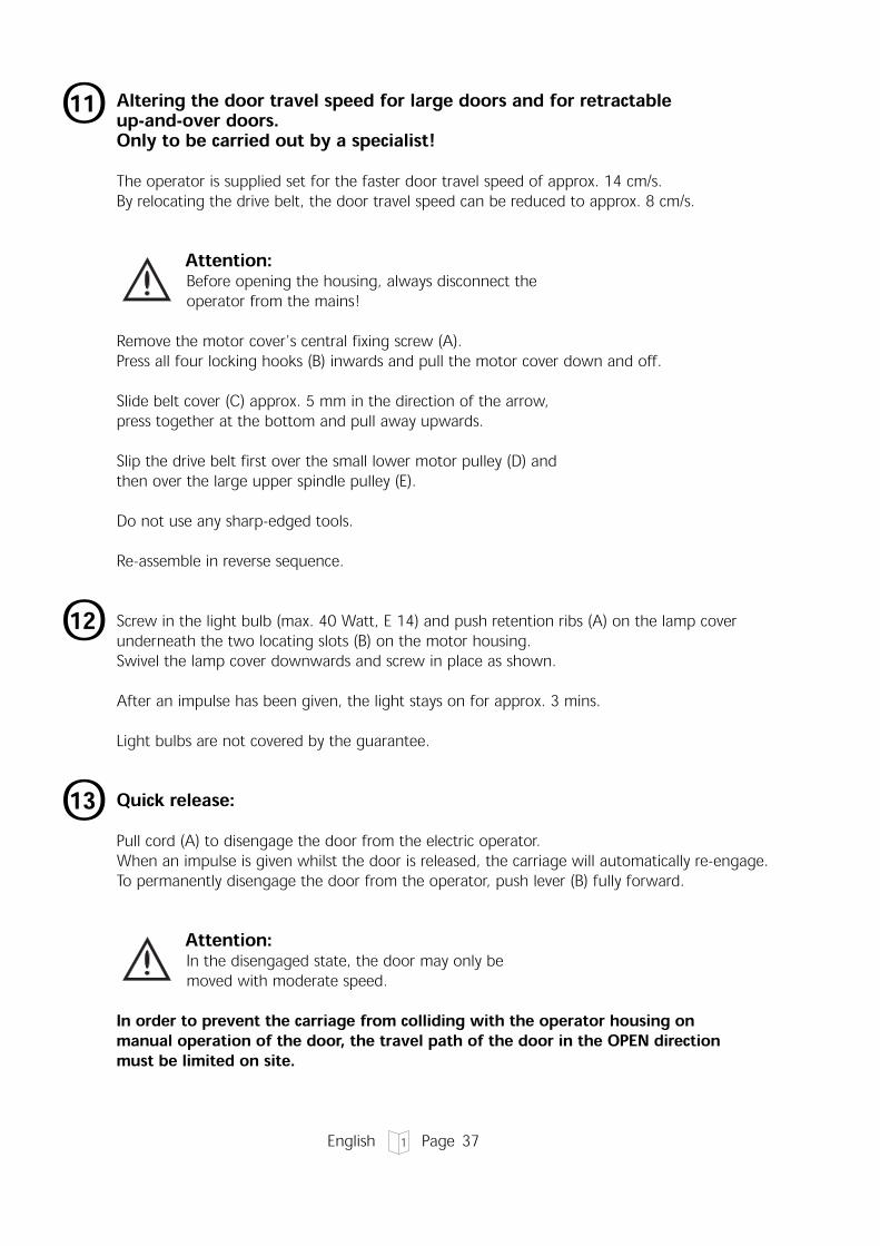
Altering the door travel speed for large doors and for retractable up-and-over doors.Only to be carried out by a specialist!The operator is supplied set for the faster door travel speed of approx. 14 cm/s. By relocating the drive belt, the door travel speed can be reduced to approx. 8 cm/s.
O11
O12 Screw in the light bulb (max. 40 Watt, E 14) and push retention ribs (A) on the lamp coverunderneath the two locating slots (B) on the motor housing. Swivel the lamp cover downwards and screw in place as shown.
After an impulse has been given, the light stays on for approx. 3 mins.
Light bulbs are not covered by the guarantee.
Attention:In the disengaged state, the door may only be moved with moderate speed.
In order to prevent the carriage from colliding with the operator housing on manual operation of the door, the travel path of the door in the OPEN direction must be limited on site.
Quick release:Pull cord (A) to disengage the door from the electric operator.When an impulse is given whilst the door is released, the carriage will automatically re-engage.To permanently disengage the door from the operator, push lever (B) fully forward.
O13
English Page 38
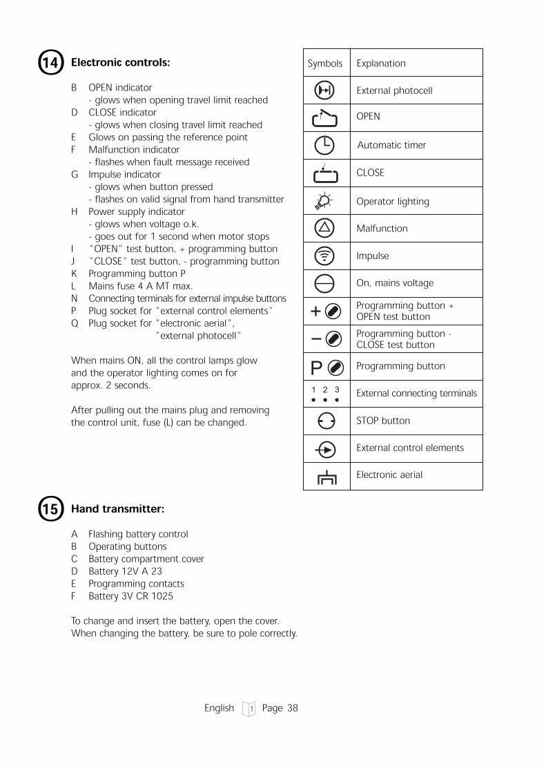
Hand transmitter:A Flashing battery controlB Operating buttonsC Battery compartment coverD Battery 12V A 23E Programming contactsF Battery 3V CR 1025
To change and insert the battery, open the cover.When changing the battery, be sure to pole correctly.
Electronic controls:B OPEN indicator
- glows when opening travel limit reachedD CLOSE indicator
- glows when closing travel limit reachedE Glows on passing the reference pointF Malfunction indicator
- flashes when fault message receivedG Impulse indicator
- glows when button pressed- flashes on valid signal from hand transmitter
H Power supply indicator- glows when voltage o.k.- goes out for 1 second when motor stops
I "OPEN" test button, + programming buttonJ "CLOSE" test button, - programming buttonK Programming button PL Mains fuse 4 A MT max.N Connecting terminals for external impulse buttonsP Plug socket for "external control elements"Q Plug socket for "electronic aerial",
"external photocell"
When mains ON, all the control lamps glow and the operator lighting comes on for approx. 2 seconds.
After pulling out the mains plug and removing the control unit, fuse (L) can be changed.
1 2 3
P
STOP button
Automatic timer
OPEN
Programming button -CLOSE test button
Programming button +OPEN test button
On, mains voltage
Impulse
Malfunction
Electronic aerial
External control elements
External connecting terminals
O14
Programming button
CLOSE
Operator lighting
O15
External photocell
Symbols Explanation

English Page 39
Batteries are not covered by the guarantee.
Attention:Only operate the hand transmitter when certain that neither persons nor objects are located within the door's range of travel.
Keep hand transmitters well out of the reach of children!
Learning the code:It is necessary to programme the two hand transmitters with the same code.
Step 1:Connect both hand transmitters using the enclosed programming cable.
Step 2:Operate the left hand transmitter and keep the button depressed.
Step 3:Operate the right hand transmitter while keeping the button on the left transmitter depressed.Programming is completed after approx. 2 secs. Remove the programming cable.
Altering the code:In the event that a hand transmitter gets lost, it is possible to reprogramme the system with anew code.
To do this, connect the programming cable to the hand transmitter to be reprogrammed.
Step 4:Short-circuit one of the two outer wires of the programming cable using the middle wire.Operate the hand transmitter for at least 5 secs. A new code is established via randomprogramming whereby the LED flashes rapidly. For multi-channel transmitters this proceduremust be carried out individually for every single button.Once the LED on the hand transmitter constantly glows, the transmitter button can be releasedand the cable removed. The recoding procedure is now completed.
Attention:After recoding the hand transmitter, the garage door operator must also bereprogrammed for the new code, since the old code has been irretrievably lost.
O16

English Page 40
Electronic aerial:Protection category: for dry buildings only.
A Connection cable to control unit with plug
B Aerial cordon
C Aerial box with adhesive surface
D Motor housing
E Front panel
Open the front panel. Plug the connection plug into the electronic control unit (see pt. 18/Q).Place the aerial box into the corresponding recess of the motor housing or stick to the sideof the motor housing.On closing the front panel, lay the connection cable into the guide channel. If the range ispoor, place the aerial on the other side or, if necessary, extend the connection cable (A) (not included in the supply package).
O17
Connecting external control elementsN Connection of site control elements may only be made to the connecting terminals
1 GND2 IMPULSE3 24 V DC max. 50 mA
Attention:The connections must be potential-free.External voltage will destroy the electronics.
R Connection cable for control elements (Marantec system cabling). To connect, remove short-circuit plug (T) (button inside or key switch outside; not included in the supply package).
S Connection for electronic aerial.
Attention:Do not insert short-circuit plug (T) into plug socket (Q).
T Short-circuit plug
O18
Mitja
Pravokotnik

English Page 41
Programming optionsO19Overview of the indicator functions and programming optionsIndicator functions
After plugging in at the mains, indicators 1 - 8 glow and the operator lighting comeson for approx. 2 seconds. The indicators and the operator lighting then go out. The control unit is in the operating state. Indicator 8 glows. (If an OPEN or CLOSE travel limit is reached, the corresponding LED glows as well).
Error messagesIf the MALFUNCTION indicator flashes, after briefly pressing button P thecorresponding error number is displayed (indicators flash erratically). The error number is arrived at by adding together the flashing numbers. See pt. 26 "Error numbers".
Programming the basic functions of the operatorPress button P for longer than 2 seconds. The control unit then changes from theoperating state to the programming state of the basic functions. Indicator 1 flashes,all other indicators glow. Now release button P.
Using the O+ or O- buttons, changes can be made in the programming menu andthen stored by pressing button P. (If button P is pressed without any change havingbeen made via the O+ or O- buttons, the programming menu is skipped and thesettings remain unchanged.) After the last programming menu, programming of thebasic functions of the operator is completed; recognizable by all the indicators goingout in the sequence 8 - 1.
Programming menus1. Photocell, operation with or without external photocell2. OPEN travel limit3. CLOSE travel limit4. OPEN automatic cut-out5. CLOSE automatic cut-out6. Coding the remote con-trol
Programming the extended operator functionsPress button P for longer than 10 seconds. The control unit than changes from theoperating state to the programming level for extended operator functions. Indicator 3 flashes rapidly, all other indicators glow. Whilst continuing to press button P, use buttons O+ or O- to select the desired programming level(indicator of the level flashes rapidly, all other indicators glow). Now release button P.
} (power limit)

English
The first programming menu of the chosen level is selected (indicator 1 flashes, all other indicators glow). Using the O+ or O- buttons changes can be made in theprogramming menu and then stored by pressing button P. (If button P is pressedwithout any change having been made via the O+ or O- buttons, the programmingmenu is skipped and the settings remain unchanged.) After the last programming menu, programming of the extended operator functionsis completed; recognizable by all the indicators going out in the sequence 8 - 1.
Notes on programmingThe programmed in data cannot be deleted but only overwritten. If the control unit is in the programming mode and none of the programming but-tons (O+ , O- or P) are pressed within 30 seconds, the programming procedure isaborted. The control unit changes to the operating state. The MALFUNCTION indicator flashes. By briefly pressing button P, the error number is displayed (7 = programming aborted).
Page 42
Explanation of the extended operator functions (see table for details)Programming level 3: Automatic timer
Functions Explanation- Open phase
- Warning phase
- Start-up warning
- Early closing after passing thethrough-traffic photocell
The length of time during which the door remains openbefore it automatically closes again.
The length of time the signal light flashes before thedoor automatically closes again.
The length of time the signal light flashes before thedoor starts to move.
The door neither closes after the set open phase nor early after the through-traffic photocell has been passed.
Programming level 5: Operator lighting / Signal lightsFunctions Explanation- Lighting phase
- Signal lights
- Lighting
The length of time the operator lighting stays on afterthe door has started to move
The signal lights flash or glow on power operation of thedoor.
The operator lighting flashes or glows during thewarning phase.

English Page 43
O20
Programming the control unit• As soon as the control unit is switched on, it runs a self-test, recognizable through the
indicators 1 - 8 and the operator lighting which glow for approx. 1 second.Afterwards the control unit is in the operating state (indicator 8 glows).
• If button P is pressed for longer than 2 seconds, the control unit changes to theprogramming mode.
• By repressing button P the programming menus necessary for programming the basicoperator settings are selected in turn.
• If a programming menu is skipped, the setting remains unchanged.• Using the A or B buttons, changes can be made in the corresponding programming
menu which can then be stored by pressing button P.• If the control unit is in the programming mode and 30 seconds elapse without any of the
3 programming buttons having been pressed, the programming process is aborted and thecontrol unit returns to its operating state (error message 7, see pt. 26).
• On misprogramming there is no need to reset because all the stored settings can bereprogrammed.
PLED OFFLED glowsLED flashesLED flashes rapidly
O21
Programming the electronic control unit:A Indicator programme external photocellB Indicator programme 'OPEN' travel limitC Indicator programme automatic timerD Indicator programme 'CLOSE' travel limitE Indicator programme light phaseF Indicator programme power limit
(indicators 6 and 2 flashing: 'OPEN' power limit)(indicators 6 and 4 flashing: 'CLOSE' power limit)
G Indicator programme remote controlI Programming button AJ Programming button BK Programming button P (programming mode, menu selection/store programming)
To display the electronic control unit fault message:In the case of a fault message, the cause of the fault can be displayed, see pt. 26.
K Programming button P to display fault (press briefly)1 - 8 Display of fault numbers (flash erratically)
for example: numbers 8 and 2 flash together:8 + 2 = fault number 10 (see pt. 26)

English Page 44
1. Programming an external photocell(The door operator is preprogrammed for connecting to an externalphotocell to monitor the through-traffic area. If this photocell is notconnected, the operator must be reprogrammed in accordancewith pt. 21/1. Otherwise the door can only be closed by press and hold.)
• Press programming button P for approx. 2 seconds until indicator 1 flashes.• The external photocell can be connected via the A button.• Indicator 1 glows.• By pressing the B button, the operator can be operated without an external
photocell.• Indicator 1 flashes.• Store by pressing programming button P.
2. Programming the 'OPEN' travel limit
• Indicator 2 flashes.• Allow the door to reach its end-of-travel 'OPEN' position by operating the A or B
buttons (operator runs only by press and hold and without the power limit).• Store by pressing programming button P.

English Page 45
3. Programming the 'CLOSE' travel limit
• Indicator 4 flashes.• Allow the door to reach its end-of-travel 'CLOSE' position by operating the A or B
buttons (operator runs only by press and hold and without the power limit).• Store by pressing programming button P.
4. Programming the 'OPEN' automatic cut-out
• Indicators 2 and 6 flash.• By operating the A or B buttons, the automatic cut-out can be set in stages from 1
(most sensitive setting) to 16.
Indicator 1 flashes = stage 1Indicator 1 glows = stage 2Indicator 1 glows, indicator 2 flashes = stage 3…Indicators 1 to 8 glow = stage 16
• Store by pressing programming button P.Set the automatic cut-out to be as sensitive as possible(150 N max. at the closing edge).

English Page 46
tnaMar ec
5. Programming the 'CLOSE' automatic cut-out
• Indicators 4 and 6 flash.• By operating the A or B buttons, the automatic cut-out can be set in
stages from 1 (most sensitive setting) to 16.
Indicator 1 flashes = stage 1Indicator 1 glows = stage 2Indicator 1 glows, indicator 2 flashes = stage 3…Indicators 1 to 8 glow = stage 16
• Store by pressing programming button P.Set the automatic cut-out to be as sensitive as possible(150 N max. at the closing edge).
• Indicator 7 flashes• The multi-bit hand transmitter is precoded at the factory.
Operate the corresponding button of the hand transmitter until LED 7 flashes rapidly
6. Programming the remote control

English Page 47
Store programming
Programming individual functionse.g. the 'CLOSE' automatic cut-out• Press programming button P for approx. 2 seconds until indicator 2 flashes.• Repeatedly press programming button P until indicators 4 and 6 flash.• Carry out programming (see pt. 21/5).• Press programming button P again to complete the programming process;
recognizable by a running light through all the indicators.
• The code is stored by pressing programmingbutton P and the programming process is completed; recognizable by running light throughall the indicators.
• The control unit is now in the operating state(in the event of a power failure all settings are retained).
P
P Level 3: Automatic timer
Programming table Level 3
If an automatic timer is used, an external photocell to monitor the through-traffic area must be connected and activated in accordance with pt 21/1 (Earlyclosing afterdriving past the through-traffic photocell).Otherwise no automatic timer function is possible.
10 seconds
• The control unit is in the operating state.• If button P is pressed for longer than 10 seconds, the control unit changes to the
programming level for extended operator functions (indicator 3 flashes, all otherindicators glow).
• Release button P. Now indicator 1 flashes.• The open phase can now be set using the A or B buttons
(see table of phase settings, pt 22).

English Page 48
Programming table Level 3Automatic timer
23456
78 1
23456
78 1 2
3456
78 1 2
3456
78 1 2
3456
78 1 2
3456
78 1 2
3456
78 1 2
3456
78 1 2
3456
78 1
Menu 2: Warning phase
Warning phase in seconds:
P
deactivated 2 5 10 15 20 25 30
23456
78 1
23456
78 1 2
3456
78 1 2
3456
78 1 2
3456
78 1 2
3456
78 1 2
3456
78 1 2
3456
78 1 2
3456
78 1
Menu 1: Open phase
Open phase in seconds:
P
deactivated 5 10 15 20 25 30 35

English Page 49
LED OFFLED glowsLED flashesLED flashes rapidlyFactory setting
23456
78 1 2
3456
78 1 2
3456
78 1 2
3456
78 1 2
3456
78 1 2
3456
78 1 2
3456
78 1 2
3456
78 1
• Once button P is no longer pressed, indicator 2 (warning phase) flashes.• Using the A or B buttons, the warnimg phase can be set (see table).
Minimum value: 2 secondsMaximum value: 70 seconds
• Store by pressing programming button P.
35 40 45 50 55 60 65 70
23456
78 1 2
3456
78 1 2
3456
78 1 2
3456
78 1 2
3456
78 1 2
3456
78 1 2
3456
78 1 2
3456
78 1
• Once button P is no longer pressed, indicator 1 (open phase) flashes.• Using the A or B buttons, the open phase can be set (see table).
Minimum value: 5 secondsMaximum value: 255 seconds
• Store by pressing programming button P.
40 50 80 100 120 150 180 255

English Page 50
Programming table Level 3Automatic timer (continued)
23456
78 1
23456
78 1 2
3456
78 1
Menu 4: Earlyclosing after driving past the through-traffic photocellP
YesNo
23456
78 1
23456
78 1 2
3456
78 1 2
3456
78 1 2
3456
78 1 2
3456
78 1 2
3456
78 1 2
3456
78 1 2
3456
78 1
Menu 3: start-up warning
start-up warning in seconds:
P
10 2 3 4 5 6 7

English Page 51
LED OFFLED glowsLED flashesLED flashes rapidlyFactory setting
• Once button P is no longer pressed, indicator 4(earlyclosing after driving past the through-traffic photocell) flashes.
• Using the A or B buttons, the function 'early closing after driving past thethrough-traffic photocell' or a set time phase can be programmed.
Indicator 1 flashes: Door closes after the set time phase.Indicator 1 glows: Door closes after driving past the through-traffic photocell.
• Complete the programming process by once again pressing programming button P; recogniz-able by all indicators going out in the sequence 8 - 1.
• Afterwards, the control unit returns to the operating state (indicator 8 glows; if the door is inan open or closed state, the corresponding indicators 2 or 4 also glow).
• Once button P is no longer pressed, indicator 3 (start-up warning) flashes.• Using the buttons, the start-up warning can be set (see table).
Minimum value: 0 secondsMaximum value: 7 seconds
• Store by pressing programming button P.

English Page 52
Programming table Level 5operator lighting/signal lights
The operator allows connection of an external signal light, provided the relay retrofit kit 'OPEN-CLOSE+light door function' for standard operators in a housing (item no. 152 137) is connected and the automatic timer is activated. The output can be programmed in such a way that the signal lights flash or glow.
23456
78 1
23456
78 1 2
3456
78 1
Menu 2: signal lightsP
glowing flashing
23456
78 1
23456
78 1 2
3456
78 1 2
3456
78 1 2
3456
78 1 2
3456
78 1 2
3456
78 1 2
3456
78 1 2
3456
78 1
Menu 1: lighting phase
lighting phase in seconds:
P
2 95 100 110 120 130 140 150

English Page 53
• Once button P is no longer pressed, indicator 2 (signal lights) flashes.• Using the A or B buttons, the signal lights function can be set.
Indicator 1 flashes: external signal light glows.Indicator 1 glows: external signal light flashes.
• Store by pressing programming button P.
23456
78 1 2
3456
78 1 2
3456
78 1 2
3456
78 1 2
3456
78 1 2
3456
78 1 2
3456
78 1 2
3456
78 1
• Once button P is no longer pressed, indicator 1 (lighting phase) flashes.• Using the A or B buttons, the lighting phase can be set (see table).
• Store by pressing programming button P.
160 170 180 190 200 210 220 240
• The control unit is in the operating state.• If button P is pressed for longer than 10 seconds, the control unit changes to the program-
ming level for extended operator functions (indicator 3 flashes rapidly).• Keep button P depressed and using the A oder B buttons select programming level 5
(indicator 5 flashes, all other indicators glow).• Release button P.

English Page 54
Programming table Level 5operator lighting/signal lights (continued)
23456
78 1
23456
78 1 2
3456
78 1
Menu 3: LightingP
Operatorlightingglows duringthe warningphase
Operatorlightingflashesduring thewarningphase

English Page 55
• Once button P is no longer pressed, indicator 3 (lighting) flashes.• Using the A or B buttons, the lighting function can be set (see table).
Indicator 1 flashes: operator lighting glows during the warning phase.Indicator 1 glows: operator lighting flashes during the warning phase.
• Store by pressing programming button P.
LED OFFLED glowsLED flashesLED flashes rapidlyFactory setting

English Page 56
Brief programming instructions for the specialistOperating state (indicator 8 glows; if the door is in an open or closed state,
the corresponding indicators 2 or 4 also glow).
tnaMar ec
P P
P
P
P
P
P
P
P
P
P
P
23456
78 1
23456
78 1
23456
78 1
23456
78 1
23456
78 1
Programming an external photocell
The programm is stored by pressing programming button P and theprogramming process is completed; recognizable by running light throughall the indicators. The control unit is now in the operating state.
Programming the 'OPEN' travel limit
Programming the 'CLOSE' travel limit
Programming the 'OPEN' automatic cut-out
Programming the 'CLOSE' automatic cut-out
+-
+-
+-
+-
+-
Programming the remote control

English Page 57
P
P
P
23456
78 1
23456
78 1
23456
78 1
23456
78 1
10 seconds
The programm is stored by pressing programming button P and theprogramming process is completed; recognizable by running light throughall the indicators. The control unit is now in the operating state.
Level 3: Automatic timer
Menu 1: Open phase
Menu 2: Warning phase
Menu 3: Start-up warning
Menu 4: Earlyclosing after driving past thethrough-traffic photocell
Level 5: Operator lighting/signal lights
Menu 1: Lighting phase
Menu 2: Signal lights
Menu 3: Lihgting
LED OFFLED glowsLED flashesLED flashes rapidly
P
-+
+-
+-
+-
+-
+-
+-
+-

EnglishPage 58
2 sek.95 sek.
100 sec.110 sec.120 sec.130 sec.140 sec.150 sec.160 sec.170 sec.180 sec.190 sec.200 sec.210 sec.220 sec.240 sec.
deactivated1 sec.2 sec.3 sec.4 sec.5 sec.6 sec.7 sec.
--------
deactivated2 sec.5 sec.
10 sec.15 sec.20 sec.25 sec.30 sec.35 sec.40 sec.45 sec.50 sec.55 sec.60 sec65 sec.70 sec.
deactivated5 sec.
10 sec.15 sec.20 sec.25 sec.30 sec.35 sec.40 sec.50 sec.80 sec.
100 sec.120 sec.150 sec.180 sec.255 sec.
123456789
10111213141516
LED Indicator Menu 1:Open phase
Level 3: Automatic timer Leve 5: operator lighting/signallights
Menu 2:Warning phase
Menu 3:Start-up warning
Menu 1:Lighting phase
Deactivating the automatic timer (both phases without function)If in accordance with the table either the open phase or the warning phase is set 'without function', then the automatic timer is switched off.
= Factory settings
Comfort 150/160 AC programming table O22

English Page 59
O23 Cable connecting planA Comfort 150 / 160 Operator
B Electric socket with earth contact 220V - 240V, 50 Hz (on site)
C Electronic aerial
D Comfort 150 / 160 control unit
E Marantec Command Series interior keypad with connection cable
F Marantec Command Series key switch
Circuit diagram B-MC 150 / 160C1 Motor capacitorF1 Fuse (max. 4A)H1 Operator lightingM1 Motor with thermal overload
protectionS x) Main switch or "emergency-off"
button (on site)S1 x) "Impulse" buttonS21 RPM sensorS22 Reference point sensorX0 +) Mains electric socketX1 Mains cable with plug
Connecting terminals:X2c Command units
Plug connections:X10 External control elementsX20 Electronic aerial
External photocell
Accessories connection:W20 Electronic aerialXS10 -) External control elements
Marantec Command Series
Attention:Observe local safety regulations!Always lay mains cable and control cable separately.
Attention:Low voltage!External voltage at the plug sockets X2c, X10 to X20 will completely destroy the electronics.
O24
+) on sitex) if fitted-) For connection, remove short-circuit plug

English Page 60
O25 Test Instructions - only for the specialist -Trouble shooting:
P2
1
3
45
6
7
8
FaultIndicator 8 doesn'tglow.
Indicator 6 flashes.Fault 10
Indicator 6 flashes.Fault 6 or 15
Drive only operatesin "OPEN" but notin "CLOSE"direction.Fault 15No response onimpulse.Indicator 7 glows
No response onimpulse.Fault 36Indicator 7 doesn'tflash rapidly onimpulse from handtransmitter
Insufficient rangeof remote control(less than 5 m).
Indicator 6 flashes.Fault 9
CauseNo voltage.
Thermal overload protection in motoractivated.Defective control unit.
Automatic cut-out set too sensitively.Door movement too sluggish.Door blocks.External photocell defective orinterrupted.
Photocell (pt. 21/1) programmed, butnot connected.
Connecting terminals for "IMPULSE"button bridged, e.g. due toshort-circuit or wrong terminalconnection.
Short-circuit plug removed (pt. 18/T),but "STOP" button not connected.
Electronic aerial disconnected.
Hand transmitter coding is notconsistent with receiver coding.Flat battery.
Hand transmitter, control unitelectronics or electronic aerial defective.Flat battery.
Wrongly positioned electronic aerial.
RPM sensor defective.
Door too sluggish.
RemedyCheck mains supply. Check electric socket.Check operator mains fuse (pt. 14/L).
Allow motor to cool down.
Cut off mains supply to operator.Unscrew control unit, pull slightly forward andwithdraw the connecting plug.Remove control unit and have it checked.
Re-set automatic cut-out to be less sensitive (pt. 21/3 - "OPEN" direction, pt. 21/4 -"CLOSE" direction). Ensure door moves easily.Remove obstruction or have photocell checked.
Reprogramme photocell function or connectphotocell.
Temporarily isolate cabled key switches orinterior push buttons from control unit.Remove plug (pt. 18/T), insert plug (pt. 18/R)and look for cable fault.
Connect "STOP" button.
Connect aerial to control unit (pt. 17).
Check coding (pt. 21/6)
Insert new 12V battery A 23 (pt. 15). FlashingLED in transmitter indicates battery condition.
Have all 3 components checked.
Insert new 12V A 23 battery (pt. 15). FlashingLED in transmitter indicates battery condition.
Align the aerial cordon and, if possible, let ithang freely.Have operator checked.
Check door.

English Page 61
Test Instructions - Error numbers -The error number is displayed on briefly pressing programming button P.
O27 Putting into operationPower-operated windows, doors and gates for industrial or commercial use must be checked by a specialist after initial installation and then regularly at intervals of 1 year minimum.
Maintenance instructionsThe Comfort 150 / 160 garage door operator is virtually maintenance-free. However, all movable parts of the door and operator system should be checked regularly and kept in an easily movable condition. The door must be easy to operate manually. The separate door counterbalance mechanism must be checked regularly. The "OPEN" and "CLOSE" settings of the automatic cut-out should be checked regularly.
O26Fault Indicator flashes erraticallyError numberPhotocell actuated Indicator 66Programming aborted Indicator 77Reference point switch defective Indicator 88Defective RPM sensorAnti-lock system actuated
Indicator 8 + 19
Power limit Indicator 8 + 210Excess travel stop Indicator 8 + 311Photocell self-monitoring unit not o.k. Indicator 8 + 715Power limit self-monitoring unit Indicator 8 + 7 + 116Learned power limit Indicator 8 + 7 + 6 + 5 + 228Response sensitivity of power limit Indicator 8 + 7 + 6 + 5 + 127Static current circuit broken Indicator 1 - 836
English Page 62
Technical data:Comfort 150 / 160Garage Door OperatorConnected loads:230 V, 50 Hz260 W
Door travel speed:0.14 m/s0.08 m/s
Push and pull force:Comfort 150: 500 NComfort 160: 700 N
Excess travel stop:88 seconds
Automatic timer device:with additional relay for signal lights connection and through-traffic photocell (available as accessories). Warning phase adjustable from 2 to 70 seconds. Open phase adjustable from 5 - 255 seconds.
Lighting:1 x 40 W E 14, goes out automatically after approx. 180 secs.
Control voltage:Low voltage below 24 V DC.
Automatic cut-out:Electronic power limit through microprocessor and RPM sensor.
Anti-lock system:Through microprocessor and RPM sensor.
Protection category:For dry buildings only.
O28