COMESA HARMONISED COMESA/DHS STANDARD 227 …programmes.comesa.int/attachments/article/152/DHS...
66
COMESA HARMONISED COMESA/DHS STANDARD 227-1: 2005 Power cables with extruded insulation and their accessories for rated voltages from 1 kV (Um = 1,2 kV) up to 30 kV (Um = 36 kV) - Part 1: Cables for rated voltages of 1 kV (Um = 1,2 kV) and 3 kV (Um = 3,6 kV) REFERENCE: DHS 227-1: 2005
Transcript of COMESA HARMONISED COMESA/DHS STANDARD 227 …programmes.comesa.int/attachments/article/152/DHS...

COMESA HARMONISED COMESA/DHS STANDARD 227-1: 2005
Power cables with extruded insulation and their accessories for rated voltages from 1 kV (Um = 1,2 kV) up to 30 kV (Um = 36 kV) - Part 1: Cables for rated voltages of 1 kV (Um = 1,2 kV) and 3 kV (Um = 3,6 kV)
REFERENCE: DHS 227-1: 2005

Foreword The Common Market for Eastern and Southern Africa (COMESA) was established in 1994 as a regional economic grouping consisting of 20 member states after signing the co-operation Treaty. In Chapter 15 of the COMESA Treaty, Member States agreed to co-operate on matters of standardisation and Quality assurance with the aim of facilitating the faster movement of goods and services within the region so as to enhance expansion of intra-COMESA trade and industrial expansion. Co-operation in standardisation is expected to result into having uniformly harmonised standards. Harmonisation of standards within the region is expected to reduce Technical Barriers to Trade that are normally encountered when goods and services are exchanged between COMESA Member States due to differences in technical requirements. Harmonized COMESA Standards are also expected to result into benefits such as greater industrial productivity and competitiveness, increased agricultural production and food security, a more rational exploitation of natural resources among others. COMESA Standards are developed by the COMESA experts on standards representing the National Standards Bodies and other stakeholders within the region in accordance with international procedures and practices. Standards are approved by circulating Final Draft Harmonized Standards (FDHS) to all member states for a one Month vote. The assumption is that all contentious issues would have been resolved during the previous stages or that an international or regional standard being adopted has been subjected through a development process consistent with accepted international practice. COMESA Standards are subject to review, to keep pace with technological advances. Users of the COMESA Harmonized Standards are therefore expected to ensure that they always have the latest version of the standards they are implementing. This COMESA standard is technically identical to the International Standard IEC 60502-1:2004.
A COMESA Harmonized Standard does not purport to include all necessary provisions of a contract. Users are responsible for its correct application.

Power cables with extruded insulation and their accessories for rated voltages from 1 kV (Um = 1,2 kV) up to 30 kV (Um = 36 kV) –
Part 1: Cables for rated voltages of 1 kV ((Um = 1,2 kV) and 3 kV (Um = 3,6 kV)
Reference number IEC 60502-1:2004(E)
INTERNATIONAL STANDARD
IEC60502-1
Second edition2004-04
This English-language version is derived from the original bilingual publication by leaving out all French-language pages. Missing page numbers correspond to the French-language pages.

Publication numbering
As from 1 January 1997 all IEC publications are issued with a designation in the 60000 series. For example, IEC 34-1 is now referred to as IEC 60034-1.
Consolidated editions
The IEC is now publishing consolidated versions of its publications. For example, edition numbers 1.0, 1.1 and 1.2 refer, respectively, to the base publication, the base publication incorporating amendment 1 and the base publication incorporating amendments 1 and 2.
Further information on IEC publications
The technical content of IEC publications is kept under constant review by the IEC, thus ensuring that the content reflects current technology. Information relating to this publication, including its validity, is available in the IEC Catalogue of publications (see below) in addition to new editions, amendments and corrigenda. Information on the subjects under consideration and work in progress undertaken by the technical committee which has prepared this publication, as well as the list of publications issued, is also available from the following:
• IEC Web Site (www.iec.ch)
• Catalogue of IEC publications
The on-line catalogue on the IEC web site (www.iec.ch/searchpub) enables you to search by a variety of criteria including text searches, technical committees and date of publication. On-line information is also available on recently issued publications, withdrawn and replaced publications, as well as corrigenda.
• IEC Just Published
This summary of recently issued publications (www.iec.ch/online_news/ justpub) is also available by email. Please contact the Customer Service Centre (see below) for further information.
• Customer Service Centre
If you have any questions regarding this publication or need further assistance, please contact the Customer Service Centre:
Email: [email protected] Tel: +41 22 919 02 11 Fax: +41 22 919 03 00

Power cables with extruded insulation and their accessories for rated voltages from 1 kV (Um = 1,2 kV) up to 30 kV (Um = 36 kV) –
Part 1: Cables for rated voltages of 1 kV ((Um = 1,2 kV) and 3 kV (Um = 3,6 kV)
For price, see current catalogue
IEC 2004 Copyright - all rights reserved
No part of this publication may be reproduced or utilized in any form or by any means, electronic or mechanical, including photocopying and microfilm, without permission in writing from the publisher.
International Electrotechnical Commission, 3, rue de Varembé, PO Box 131, CH-1211 Geneva 20, SwitzerlandTelephone: +41 22 919 02 11 Telefax: +41 22 919 03 00 E-mail: [email protected] Web: www.iec.ch
INTERNATIONAL STANDARD
IEC60502-1
Second edition2004-04
XA Commission Electrotechnique InternationaleInternational Electrotechnical CommissionМеждународная Электротехническая Комиссия
PRICE CODE

60502-1 IEC:2004 3
CONTENTS
FOREWORD......................................................................................................................... 11 1 Scope ............................................................................................................................. 15 2 Normative references...................................................................................................... 15 3 Terms and definitions ..................................................................................................... 19
3.1 Definitions of dimensional values (thicknesses, cross-sections, etc.) ...................... 19 3.2 Definitions concerning the tests ............................................................................. 19
4 Voltage designations and materials ................................................................................. 21 4.1 Rated voltages ...................................................................................................... 21 4.2 Insulating compounds ............................................................................................ 23 4.3 Sheathing compounds ........................................................................................... 25
5 Conductors ..................................................................................................................... 25 6 Insulation........................................................................................................................ 25
6.1 Material ................................................................................................................. 25 6.2 Insulation thickness ............................................................................................... 25
7 Assembly of multicore cables, inner coverings and fillers................................................. 29 7.1 Inner coverings and fillers ...................................................................................... 29 7.2 Cables with rated voltage 0,6/1 (1,2) kV ................................................................. 31 7.3 Cables with rated voltage 1,8/3 (3,6) kV ................................................................. 33
8 Metallic layers for single-core and multicore cables ......................................................... 33 9 Metallic screen ............................................................................................................... 35
9.1 Construction .......................................................................................................... 35 9.2 Requirements ........................................................................................................ 35
10 Concentric conductor ...................................................................................................... 35 10.1 Construction .......................................................................................................... 35 10.2 Requirements ........................................................................................................ 35 10.3 Application............................................................................................................. 35
11 Lead sheath.................................................................................................................... 35 12 Metallic armour ............................................................................................................... 37
12.1 Types of metallic armour........................................................................................ 37 12.2 Materials ............................................................................................................... 37 12.3 Application of armour............................................................................................. 39 12.4 Dimensions of the armour wires and armour tapes ................................................. 41 12.5 Correlation between cable diameters and armour dimensions ................................ 41 12.6 Round or flat wire armour ...................................................................................... 43 12.7 Double tape armour ............................................................................................... 43
13 Oversheath ..................................................................................................................... 43 13.1 General ................................................................................................................. 43 13.2 Material ................................................................................................................. 43 13.3 Thickness .............................................................................................................. 45
14 Test conditions ............................................................................................................... 45 14.1 Ambient temperature ............................................................................................. 45 14.2 Frequency and waveform of power frequency test voltages .................................... 45 14.3 Waveform of impulse test voltages ........................................................................ 45

60502-1 IEC:2004 5
15 Routine tests .................................................................................................................. 45 15.1 General ................................................................................................................. 45 15.2 Electrical resistance of conductors ......................................................................... 47 15.3 Voltage test ........................................................................................................... 47
16 Sample tests................................................................................................................... 49 16.1 General ................................................................................................................. 49 16.2 Frequency of sample tests ..................................................................................... 49 16.3 Repetition of tests.................................................................................................. 51 16.4 Conductor examination .......................................................................................... 51 16.5 Measurement of thickness of insulation and of non-metallic sheaths (including
extruded separation sheaths, but excluding inner extruded coverings) .................... 51 16.6 Measurement of thickness of lead sheath .............................................................. 53 16.7 Measurement of armour wires and tapes................................................................ 53 16.8 Measurement of external diameter ......................................................................... 55 16.9 Hot set test for EPR, HEPR and XLPE insulations and elastomeric sheaths............ 55
17 Type tests, electrical ....................................................................................................... 55 17.1 Insulation resistance measurement at ambient temperature ................................... 57 17.2 Insulation resistance measurement at maximum conductor temperature................. 57 17.3 Voltage test for 4 h ................................................................................................ 59 17.4 Impulse test for cables of rated voltage 1,8/3 (3,6) kV ............................................ 59
18 Type tests, non-electrical ................................................................................................ 59 18.1 Measurement of thickness of insulation.................................................................. 61 18.2 Measurement of thickness of non-metallic sheaths (including extruded
separation sheaths, but excluding inner coverings) ................................................ 61 18.3 Tests for determining the mechanical properties of insulation before and after
ageing ................................................................................................................... 61 18.4 Tests for determining the mechanical properties of non-metallic sheaths
before and after ageing.......................................................................................... 63 18.5 Additional ageing test on pieces of completed cables ............................................. 63 18.6 Loss of mass test on PVC sheaths of type ST2 ...................................................... 65 18.7 Pressure test at high temperature on insulations and non-metallic sheaths............. 65 18.8 Test on PVC insulation and sheaths and halogen free sheaths at low
temperatures ......................................................................................................... 65 18.9 Test for resistance of PVC insulation and sheaths to cracking (heat shock test) ..... 65 18.10 Ozone resistance test for EPR and HEPR insulations ............................................. 67 18.11 Hot set test for EPR, HEPR and XLPE insulations and elastomeric sheaths............ 67 18.12 Oil immersion test for elastomeric sheaths ............................................................. 67 18.13 Water absorption test on insulation ........................................................................ 67 18.14 Fire tests ..............................................................................................................67 18.15 Measurement of carbon black content of black PE oversheaths.............................. 69 18.16 Shrinkage test for XLPE insulation ......................................................................... 71 18.17 Special bending test .............................................................................................. 71 18.18 Determination of hardness of HEPR insulation ....................................................... 71 18.19 Determination of the elastic modulus of HEPR insulation........................................ 71

60502-1 IEC:2004 7
18.20 Shrinkage test for PE oversheaths ......................................................................... 73 18.21 Additional mechanical tests on halogen free oversheaths ....................................... 73 18.22 Water absorption test for halogen free oversheaths................................................ 73
19 Electrical tests after installation....................................................................................... 73 Annex A (normative) Fictitious calculation method for determination of dimensions of protective coverings .............................................................................................................. 95 A.1 General........................................................................................................................... 95 A.2 Method ........................................................................................................................... 95 Annex B (normative) Rounding of numbers......................................................................... 107 B.1 Rounding of numbers for the purpose of the fictitious calculation method....................... 107 B.2 Rounding of numbers for other purposes ....................................................................... 107 Annex C (normative) Determination of hardness of HEPR insulations ................................. 111 C.1 Test piece..................................................................................................................... 111 C.2 Test procedure ............................................................................................................. 111 Figure C.1 Test on surfaces of large radius of curvature ................................................... 113 Figure C.2 Test on surfaces of small radius of curvature................................................... 115 Table 1 Recommended rated voltages U0 ........................................................................... 21 Table 2 Insulating compounds ............................................................................................ 23 Table 3 Maximum conductor temperatures for different types of insulating compound ......... 23 Table 4 Maximum conductor temperatures for different types of sheathing compound ......... 25 Table 5 Nominal thickness of PVC/A insulation ................................................................... 27 Table 6 Nominal thickness of cross-linked polyethylene (XLPE) insulation .......................... 27 Table 7 Nominal thickness of ethylene propylene rubber (EPR) and hard ethylene propylene rubber (HEPR) insulation....................................................................................... 29 Table 8 Thickness of extruded inner covering ..................................................................... 31 Table 9 Nominal diameter of round armour wires ................................................................ 41 Table 10 Nominal thickness of armour tapes ...................................................................... 41 Table 11 Routine test voltages ........................................................................................... 49 Table 12 Number of samples for sample tests .................................................................... 51 Table 13 Electrical type test requirements for insulating compounds ................................... 75 Table 14 Non-electrical type tests (see Tables 15 to 23) .................................................... 77 Table 15 Test requirements for mechanical characteristics of insulating compounds (before and after ageing) ....................................................................................................... 79 Table 16 Test requirements for particular characteristics for PVC insulating compound....... 81 Table 17 Test requirements for particular characteristics of various thermosetting insulating compounds............................................................................................................ 83 Table 18 Test requirements for mechanical characteristics of sheathing compounds (before and after ageing) ....................................................................................................... 85

60502-1 IEC:2004 9
Table 19 Test requirements for particular characteristics for PVC sheathing compounds ........................................................................................................................... 87 Table 20 Test requirements for particular characteristics of thermoplastic PE sheathing compounds ........................................................................................................... 89 Table 21 Test requirements for particular characteristics of halogen free sheathing compound ............................................................................................................................. 91 Table 22 Test requirements for particular characteristics of elastomeric sheathing compound ............................................................................................................................. 93 Table 23 Test methods and requirements for halogen free compounds ............................... 93 Table A.1 Fictitious diameter of conductor .......................................................................... 48 Table A.2 Assembly coefficient k for laid-up cores .............................................................. 99 Table A.3 Increase of diameter for concentric conductors and metallic screens................. 101 Table A.4 Increase of diameter for additional bedding....................................................... 105

60502-1 IEC:2004 – 11 –
INTERNATIONAL ELECTROTECHNICAL COMMISSION ____________
POWER CABLES WITH EXTRUDED INSULATION
AND THEIR ACCESSORIES FOR RATED VOLTAGES FROM 1 kV (Um = 1,2 kV) UP TO 30 kV (Um = 36 kV) –
Part 1: Cables for rated voltages of 1 kV
(Um = 1,2 kV) and 3 kV (Um = 3,6 kV)
FOREWORD
1) The International Electrotechnical Commission (IEC) is a worldwide organization for standardization comprising all national electrotechnical committees (IEC National Committees). The object of IEC is to promote international co-operation on all questions concerning standardization in the electrical and electronic fields. To this end and in addition to other activities, IEC publishes International Standards, Technical Specifications, Technical Reports, Publicly Available Specifications (PAS) and Guides (hereafter referred to as “IEC Publication(s)”). Their preparation is entrusted to technical committees; any IEC National Committee interested in the subject dealt with may participate in this preparatory work. International, governmental and non-governmental organizations liaising with the IEC also participate in this preparation. IEC collaborates closely with the International Organization for Standardization (ISO) in accordance with conditions determined by agreement between the two organizations.
2) The formal decisions or agreements of IEC on technical matters express, as nearly as possible, an international consensus of opinion on the relevant subjects since each technical committee has representation from all interested IEC National Committees.
3) IEC Publications have the form of recommendations for international use and are accepted by IEC National Committees in that sense. While all reasonable efforts are made to ensure that the technical content of IEC Publications is accurate, IEC cannot be held responsible for the way in which they are used or for any misinterpretation by any end user.
4) In order to promote international uniformity, IEC National Committees undertake to apply IEC Publications transparently to the maximum extent possible in their national and regional publications. Any divergence between any IEC Publication and the corresponding national or regional publication shall be clearly indicated in the latter.
5) IEC provides no marking procedure to indicate its approval and cannot be rendered responsible for any equipment declared to be in conformity with an IEC Publication.
6) All users should ensure that they have the latest edition of this publication.
7) No liability shall attach to IEC or its directors, employees, servants or agents including individual experts and members of its technical committees and IEC National Committees for any personal injury, property damage or other damage of any nature whatsoever, whether direct or indirect, or for costs (including legal fees) and expenses arising out of the publication, use of, or reliance upon, this IEC Publication or any other IEC Publications.
8) Attention is drawn to the Normative references cited in this publication. Use of the referenced publications is indispensable for the correct application of this publication.
9) Attention is drawn to the possibility that some of the elements of this IEC Publication may be the subject of patent rights. IEC shall not be held responsible for identifying any or all such patent rights.
International Standard IEC 60502-1 has been prepared by IEC technical committee 20: Electric cables.
This second edition cancels and replaces the first edition, published in 1997, its amendment 1 (1998) and constitutes a technical revision.
The main changes with respect to the first edition relate to insulation and oversheath thickness requirements, and inclusion of constructions and requirements for halogen free cables with reduced flame propagation and low levels of smoke emission.

60502-1 IEC:2004 13
The text of this standard is based on the following documents:
FDIS Report on voting
20/683/FDIS 20/691/RVD
Full information on the voting for the approval of this standard can be found in the report on voting indicated in the above table.
This publication has been drafted in accordance with the ISO/IEC Directives, Part 2.
IEC 60502 consists of the following parts, under the general title Power cables with extruded insulation and their accessories for rated voltages from 1 kV (Um = 1,2 kV) up to 30 kV (Um = 36 kV):
Part 1: Cables for rated voltages of 1 kV (Um = 1,2 kV) and 3 kV (Um = 3,6 kV); Part 2: Cables for rated voltages from 6 kV (Um = 7,2 kV) up to 30 kV (Um = 36 kV); Part 3: Reserved; Part 4: Test requirements on accessories for cables with rated voltages from 6 kV
(Um = 7,2 kV) up to 30 kV (Um = 36 kV).
The committee has decided that the contents of this publication will remain unchanged until 2009. At this date, the publication will be
reconfirmed; withdrawn; replaced by a revised edition, or amended.

60502-1 IEC:2004 15
POWER CABLES WITH EXTRUDED INSULATION AND THEIR ACCESSORIES FOR RATED VOLTAGES FROM 1 kV (Um = 1,2 kV) UP TO 30 kV (Um = 36 kV)
Part 1: Cables for rated voltages of 1 kV
(Um = 1,2 kV) and 3 kV (Um = 3,6 kV)
1 Scope
This part of IEC 60502 specifies the construction, dimensions and test requirements of power cables with extruded solid insulation for rated voltages of 1 kV (Um = 1,2 kV) and 3 kV (Um = 3,6 kV) for fixed installations such as distribution networks or industrial installations.
This standard includes cables which exhibit properties of reduced flame spread, low levels of smoke emission and halogen-free gas emission when exposed to fire.
Cables for special installation and service conditions are not included, for example cables for overhead networks, the mining industry, nuclear power plants (in and around the containment area), submarine use or shipboard application.
2 Normative references
The following referenced documents are indispensable for the application of this document. For dated references, only the edition cited applies. For undated references, the latest edition of the referenced document (including any amendments) applies.
IEC 60038:1983, IEC standard voltages
IEC 60060-1:1989, High-voltage test techniques Part 1: General definitions and test requirements
IEC 60183:1984, Guide to the selection of high-voltage cables
IEC 60228:1978, Conductors of insulated cables
IEC 60230:1966, Impulse tests on cables and their accessories
IEC 60332-1:1993, Tests on electric cables under fire conditions Part 1: Test on a single vertical insulated wire or cable
IEC 60332-3-24:2000, Tests on electric cables under fire conditions Part 3-24: Test for vertical flame spread of vertically-mounted bunched wires or cables Category C
IEC 60502-2:1997, Power cables with extruded insulation and their accessories for rated voltages from 1 kV (Um = 1,2 kV) up to 30 kV (Um = 36 kV) Part 2: Cables for rated voltages from 6 kV (Um = 7,2 kV) up to 30 kV (Um = 36 kV)

60502-1 IEC:2004 17
IEC 60684-2:1987, Flexible insulating sleeving Part 2: Methods of test
IEC 60724:2000, Short-circuit temperature limits of electric cables with rated voltages of 1 kV (Um = 1,2 kV) and 3 kV (Um = 3,6 kV)
IEC 60754-1:1994, Test on gases evolved during combustion of materials from cables Part 1: Determination of the amount of halogen gas
IEC 60754-2:1991, Test on gases evolved during combustion of electric cables Part 2: Determination of degree of acidity of gases evolved during the combustion of materials taken from electric cables by measuring pH and conductivity
IEC 60811-1-1:1993, Common test methods for insulating and sheathing materials of electric cables Part 1: Methods for general application Section 1: Measurement of thickness and overall dimensions Tests for determining the mechanical properties
IEC 60811-1-2:1985, Common test methods for insulating and sheathing materials of electric cables Part 1: Methods for general application Section 2: Thermal ageing methods
IEC 60811-1-3:1993, Common test methods for insulating and sheathing materials of electric cables Part 1: Methods for general application Section 3: Methods for determining the density Water absorption tests Shrinkage test
IEC 60811-1-4:1985, Common test methods for insulating and sheathing materials of electric cables Part 1: Methods for general application Section 4: Tests at low temperature
IEC 60811-2-1:1998, Insulating and sheathing materials of electric and optical cables Common test methods Part 2-1: Methods specific to elastomeric compounds Ozone resistance, hot set and mineral oil immersion tests
IEC 60811-3-1:1985, Common test methods for insulating and sheathing materials of electric cables Part 3: Methods specific to PVC compounds Section 1: Pressure test at high temperature Tests for resistance to cracking
IEC 60811-3-2:1985, Common test methods for insulating and sheathing materials of electric cables Part 3: Methods specific to PVC compounds Section 2: Loss of mass test Thermal stability test
IEC 60811-4-1:1985, Common test methods for insulating and sheathing materials of electric cables Part 4: Methods specific to polyethylene and polypropylene compounds Section 1: Resistance to environmental stress cracking Wrapping test after thermal ageing in air Measurement of the melt flow index Carbon black and/or mineral content measurement in PE
IEC 61034-2: 1997, Measurement of smoke density of cables burning under defined conditions Part 2: Test procedure and requirements
ISO 48:1994, Rubber, vulcanized or thermoplastic Determination of hardness (hardness between 10 IRHD and 100 IRHD)

60502-1 IEC:2004 19
3 Terms and definitions
For the purposes of this document, the following definitions apply.
3.1 Definitions of dimensional values (thicknesses, cross-sections, etc.)
3.1.1 nominal value value by which a quantity is designated and which is often used in tables
NOTE Usually, in this standard, nominal values give rise to values to be checked by measurements taking into account specified tolerances.
3.1.2 approximate value value which is neither guaranteed nor checked; it is used, for example, for the calculation of other dimensional values
3.1.3 median value when several test results have been obtained and ordered in an increasing (or decreasing) succession, the median value is the middle value if the number of available values is odd, and the mean of the two middle values if the number is even
3.1.4 fictitious value value calculated according to the "fictitious method'' described in Annex A
3.2 Definitions concerning the tests
3.2.1 routine tests tests made by the manufacturer on each manufactured length of cable to check that each length meets the specified requirements
3.2.2 sample tests tests made by the manufacturer on samples of completed cable or components taken from a completed cable, at a specified frequency, so as to verify that the finished product meets the specified requirements
3.2.3 type tests tests made before supplying, on a general commercial basis, a type of cable covered by this standard, in order to demonstrate satisfactory performance characteristics to meet the intended application
NOTE These tests are of such a nature that, after they have been made, they need not be repeated, unless changes are made in the cable materials or design or manufacturing process which might change the performance characteristics.
3.2.4 electrical tests after installation tests made to demonstrate the integrity of the cable and its accessories as installed

60502-1 IEC:2004 21
4 Voltage designations and materials
4.1 Rated voltages
The rated voltages U0/U (Um) of the cables considered in this standard are 0,6/1 (1,2) kV and 1,8/3 (3,6) kV.
NOTE 1 The voltages given above are the correct designations although in some countries other designations are used, e.g. 1,7/3 kV or 1,9/3,3 kV instead of 1,8/3 kV.
In the voltage designation of cables U0/U (Um):
U0 is the rated power frequency voltage between conductor and earth or metallic screen for which the cable is designed;
U is the rated power frequency voltage between conductors for which the cable is designed; Um is the maximum value of the "highest system voltage'' for which the equipment may be
used (see IEC 60038).
The rated voltage of the cable for a given application shall be suitable for the operating conditions in the system in which the cable is used. To facilitate the selection of the cable, systems are divided into three categories:
Category A: this category comprises those systems in which any phase conductor that comes in contact with earth or an earth conductor is disconnected from the system within 1 min;
Category B: this category comprises those systems which, under fault conditions, are operated for a short time with one phase earthed. This period, according to IEC 60183, should not exceed 1 h. For cables covered by this standard, a longer period, not exceeding 8 h on any occasion, can be tolerated. The total duration of earth faults in any year should not exceed 125 h;
Category C: this category comprises all systems which do not fall into category A or B.
NOTE 2 It should be realized that in a system where an earth fault is not automatically and promptly isolated, the extra stresses on the insulation of cables during the earth fault reduce the life of the cables to a certain degree. If the system is expected to be operated fairly often with a permanent earth fault, it may be advisable to classify the system in Category C.
The values of U0 recommended for cables to be used in three-phase systems are listed in Table 1.
Table 1 Recommended rated voltages U0
Highest system voltage (Um)
Rated voltage (U0) kV
kV Categories A and B Category C
1,2
3,6
0,6
1,8
0,6
3,6*
* This category is covered by 3,6/6 (7,2) kV cables according to IEC 60502-2.

60502-1 IEC:2004 23
4.2 Insulating compounds
The types of insulating compound covered by this standard are listed in Table 2, together with their abbreviated designations.
Table 2 Insulating compounds
Insulating compound Abbreviated designation
a) Thermoplastic
Polyvinyl chloride intended for cables with rated voltages U0/U ≤ 1,8/3 kV
PVC/A*
b) Thermosetting:
Ethylene propylene rubber or similar (EPM or EPDM)
High modulus or hard grade ethylene propylene rubber
Cross-linked polyethylene
EPR
HEPR
XLPE
* Insulating compound based on polyvinyl chloride intended for cables with rated voltages U0/U = 3,6/6 kV is designated PVC/B in IEC 60502-2.
The maximum conductor temperatures for different types of insulating compound covered by this standard are given in Table 3.
Table 3 Maximum conductor temperatures for different types of insulating compound
Maximum conductor temperature °C
Insulating compound Normal operation
Short-circuit (5 s maximum
duration)
Polyvinyl chloride (PVC/A)
Conductor cross-section ≤300 mm2
Conductor cross-section >300 mm2
70
70
160
140
Cross-linked polyethylene
Ethylene propylene rubber
(XLPE)
(EPR and HEPR)
90
90
250
250
The temperatures in Table 3 are based on the intrinsic properties of the insulating materials. It is important to take into account other factors when using these values for the calculation of current ratings.
For example, in normal operation, if a cable directly buried in the ground is operated under continuous load (100 % load factor) at the maximum conductor temperature shown in the table, the thermal resistivity of the soil surrounding the cable may, in the course of time, increase from its original value as a result of drying-out processes. As a consequence, the conductor temperature may greatly exceed the maximum value. If such operating conditions are foreseen, adequate provisions shall be made.
For guidance on the short-circuit temperatures, reference should be made to IEC 60724.

60502-1 IEC:2004 25
4.3 Sheathing compounds
The maximum conductor temperatures for the different types of sheathing compound covered by this standard are given in Table 4.
Table 4 Maximum conductor temperatures for different types of sheathing compound
Sheathing compound Abbreviated designation
Maximum conductor temperature
in normal operation °C
a) Thermoplastic:
Polyvinyl chloride (PVC)
Polyethylene
Halogen free
ST1
ST2
ST3
ST7
ST8
80
90
80
90
90
b) Elastomeric:
Polychloroprene, chlorosulfonated polyethylene or similar polymers
SE1
85
5 Conductors
The conductors shall be either of Class 1 or Class 2 of plain or metal-coated annealed copper or of plain aluminium or aluminium alloy, or of Class 5 of plain or metal-coated copper in accordance with IEC 60228.
6 Insulation
6.1 Material
The insulation shall be extruded dielectric of one of the types listed in Table 2.
For halogen free cables, the insulation shall meet the requirements given in Table 23.
6.2 Insulation thickness
The nominal insulation thicknesses are specified in Tables 5 to 7.
The thickness of any separator shall not be included in the thickness of the insulation.

60502-1 IEC:2004 27
Table 5 Nominal thickness of PVC/A insulation
Nominal cross-sectional area of conductor
Nominal thickness of insulation at rated voltage U0/U (Um)
mm2
0,6/1 (1,2) kV mm
1,8/3 (3,6) kV mm
1,5 and 2,5
4 and 6
10 and 16
25 and 35
50 and 70
95 and 120
150
185
240
300
400
500 to 800
1 000
0,8
1,0
1,0
1,2
1,4
1,6
1,8
2,0
2,2
2,4
2,6
2,8
3,0
2,2
2,2
2,2
2,2
2,2
2,2
2,2
2,4
2,6
2,8
3,0
NOTE Any conductor cross-section smaller than those given in this table is not recommended.
Table 6 Nominal thickness of cross-linked polyethylene (XLPE) insulation
Nominal cross-sectional area of conductor
Nominal thickness of insulation at rated voltage U0/U (Um)
mm2
0,6/1 (1,2) kV mm
1,8/3 (3,6) kV mm
1,5 and 2,5 4 and 6
10 and 16 25 and 35
50 70 and 95
120 150 185 240 300 400 500 630 800
1 000
0,7 0,7 0,7 0,9 1,0 1,1 1,2 1,4 1,6 1,7 1,8 2,0 2,2 2,4 2,6 2,8
2,0 2,0 2,0 2,0 2,0 2,0 2,0 2,0 2,0 2,0 2,2 2,4 2,6 2,8
NOTE Any conductor cross-section smaller than those given in this table is not recommended.

60502-1 IEC:2004 29
Table 7 Nominal thickness of ethylene propylene rubber (EPR) and hard ethylene propylene rubber (HEPR) insulation
Nominal thickness of insulation at rated voltage U0/U (Um)
0,6/1 (1,2) kV 1,8/3 (3,6) kV
Nominal cross-sectional area of conductor
mm2 EPR mm
HEPR mm
EPR mm
HEPR mm
1,5 and 2,5 4 and 6
10 and 16 25 and 35
50 70 95
120 150 185 240 300 400 500 630 800
1 000
1,0 1,0 1,0 1,2 1,4 1,4 1,6 1,6 1,8 2,0 2,2 2,4 2,6 2,8 2,8 2,8 3,0
0,7 0,7 0,7 0,9 1,0 1,1 1,1 1,2 1,4 1,6 1,7 1,8 2,0 2,2 2,4 2,6 2,8
2,2 2,2 2,2 2,2 2,4 2,4 2,4 2,4 2,4 2,4 2,6 2,8 2,8 2,8 3,0
2,0 2,0 2,0 2,0 2,0 2,0 2,0 2,0 2,0 2,0 2,0 2,2 2,4 2,6 2,8
NOTE Any conductor cross-section smaller than those given in this table is not recommended.
7 Assembly of multicore cables, inner coverings and fillers
The assembly of multicore cables depends on the rated voltage and whether a metallic layer is applied to each core.
The following subclauses 7.1 to 7.3 do not apply to assemblies of sheathed single-core cables.
7.1 Inner coverings and fillers
7.1.1 Construction
The inner coverings may be extruded or lapped.
For cables with circular cores, except cables with more than five cores, a lapped inner covering shall be permitted only if the interstices between the cores are substantially filled.
A suitable binder is permitted before application of an extruded inner covering.

60502-1 IEC:2004 31
7.1.2 Material
The materials used for inner coverings and fillers shall be suitable for the operating temperature of the cable and compatible with the insulating material.
For halogen free cables, the inner covering and fillers shall meet the requirements given in Table 23.
7.1.3 Thickness of extruded inner covering
The approximate thickness of extruded inner coverings shall be derived from Table 8.
Table 8 Thickness of extruded inner covering
Fictitious diameter over laid-up cores
Above mm
Up to and including mm
Thickness of extruded inner covering
(approximate values) mm
25
35
45
60
80
25
35
45
60
80
1,0
1,2
1,4
1,6
1,8
2,0
7.1.4 Thickness of lapped inner coverings
The approximate thickness of lapped inner coverings shall be 0,4 mm for fictitious diameters over laid-up cores up to and including 40 mm and 0,6 mm for larger diameters.
7.2 Cables with rated voltage 0,6/1 (1,2) kV
Cables with rated voltage 0,6/1(1,2) kV may have a metallic layer collectively surrounding the cores.
NOTE The choice between cables having and cables not having a metallic layer depends upon national regulations and installation requirements for the prevention of possible dangers from mechanical damage or direct electrical contact.
7.2.1 Cables having a collective metallic layer (see Clause 8)
Cables shall have an inner covering over the laid-up cores. The inner covering and fillers shall comply with 7.1.
Metallic tapes may, however, be applied directly over the assembled cores, omitting the inner covering, provided that the nominal thickness of each tape does not exceed 0,3 mm and that the completed cable complies with the special bending test specified in 18.17.

60502-1 IEC:2004 33
7.2.2 Cables having no collective metallic layer (see Clause 8)
The inner covering may be omitted, provided the outer shape of the cable remains practically circular and no adhesion occurs between cores and sheath.
The oversheath may penetrate into the interstices of the cores, except in the case of thermoplastic oversheaths over circular cores exceeding 10 mm2.
If, however, an inner covering is applied, its thickness need not comply with 7.1.3 or 7.1.4.
7.3 Cables with rated voltage 1,8/3 (3,6) kV
Cables with rated voltage 1,8/3 (3,6) kV shall have a metallic layer surrounding the cores either individually or collectively.
7.3.1 Cables having only a collective metallic layer (see Clause 8)
Cables shall have an inner covering over the laid-up cores. The inner covering and fillers shall comply with 7.1 and shall be non-hygroscopic.
7.3.2 Cables having a metallic layer over each individual core (see Clause 9)
The metallic layers of the individual cores shall be in contact with each other.
Cables with an additional collective metallic layer (see Clause 8) of the same material as the underlying individual metallic layers shall have an inner covering over the laid-up cores. The inner covering and fillers shall comply with 7.1 and shall be non-hygroscopic.
When the underlying individual metallic layers and the collective metallic layer are of different materials, they shall be separated by an extruded sheath of one of the materials specified in 13.2. For lead-sheathed cables, the separation from the underlying individual metallic layers may be obtained by an inner covering according to 7.1.
For cables having neither armour, nor concentric conductor, nor other collective metallic layer (see Clause 8), the inner covering may be omitted, provided the outer shape of the cable remains practically circular. The oversheath may penetrate into the interstices of the cores, except in the case of thermoplastic oversheaths over circular cores exceeding 10 mm2. If, however, an inner covering is applied, its thickness need not comply with 7.1.3 or 7.1.4.
8 Metallic layers for single-core and multicore cables
The following types of metallic layers are included in this standard:
a) metallic screen (see Clause 9); b) concentric conductor (see Clause 10); c) lead sheath (see Clause 11); d) metallic armour (see Clause 12).

60502-1 IEC:2004 35
The metallic layer(s) shall comprise one or more of the types listed above and shall be non-magnetic when applied to either single-core cables or individual cores of multicore cables.
9 Metallic screen
9.1 Construction
The metallic screen shall consist of one or more tapes, or a braid, or a concentric layer of wires or a combination of wires and tape(s).
It may also be a sheath or, in the case of a collective screen, an armour which complies with 9.2.
When choosing the material of the screen, special consideration shall be given to the possibility of corrosion, not only for mechanical safety but also for electrical safety.
Gaps in the screen shall comply with the national regulations and/or standards.
9.2 Requirements
The dimensional, physical and electrical requirements of the metallic screen shall be determined by national regulations and/or standards.
10 Concentric conductor
10.1 Construction
Gaps in the concentric conductor shall comply with national regulations and/or standards.
When choosing the material of the concentric conductor, special consideration shall be given to the possibility of corrosion, not only for mechanical safety but also for electrical safety.
10.2 Requirements
The dimensional and physical requirements of the concentric conductor and its electrical resistance shall be determined by national regulations and/or standards.
10.3 Application
When a concentric conductor is required, it shall be applied over the inner covering in the case of multicore cables. In the case of single-core cables, it shall be applied either directly over the insulation or over a suitable inner covering.
11 Lead sheath
The sheath shall consist of lead or lead alloy and shall be applied as a reasonably tight-fitting seamless tube.

60502-1 IEC:2004 37
The nominal thickness shall be calculated using the following formula:
a) for all single-core cables or assemblies thereof:
tpb = 0,03 Dg + 0,8
b) for all cables with sector-shaped conductors:
tpb = 0,03 Dg + 0,6
c) for all other cables:
tpb = 0,03 Dg + 0,7
where tpb is the nominal thickness of lead sheath, in millimetres; Dg is the fictitious diameter under the lead sheath, in millimetres (rounded to the first
decimal place in accordance with Annex B).
In all cases the smallest nominal thickness shall be 1,2 mm. Calculated values shall be rounded to the first decimal place (see Annex B).
12 Metallic armour
12.1 Types of metallic armour
The armour types covered by this standard are as follows:
a) flat wire armour; b) round wire armour; c) double tape armour.
NOTE For cables with rated voltage 0,6/1 (1,2) kV with conductor cross-sectional areas not exceeding 6 mm2, galvanized steelwire braid armour may be provided by agreement between the manufacturer and the purchaser.
12.2 Materials
Round or flat wires shall be of galvanized steel, copper or tinned copper, aluminium or aluminium alloy.
Tapes shall be of steel, galvanized steel, aluminium or aluminium alloy. Steel tapes shall be hot- or cold-rolled of commercial quality.
In those cases where the steel armour wire layer is required to comply with a minimum conductance, it is permissible to include sufficient copper or tinned copper wires in the armour layer to ensure compliance.
When choosing the material of the armour, special consideration shall be given to the possibility of corrosion, not only for mechanical safety, but also for electrical safety, especially when the armour is used as a screen.
The armour of single-core cables for use on a.c. systems shall consist of non-magnetic material, unless a special construction is chosen.

60502-1 IEC:2004 39
12.3 Application of armour
12.3.1 Single-core cables
In the case of single-core cables, an inner covering, extruded or lapped, of the thickness specified in 7.1.3 or 7.1.4, shall be applied under the armour.
12.3.2 Multicore cables
In the case of multicore cables, the armour shall be applied on an inner covering complying with 7.1 except for special applications using metallic tapes, see 7.2.1.
12.3.3 Separation sheath
When the underlying metallic layer and the armour are of different materials, they shall be separated by an extruded sheath of one of the materials specified in 13.2.
For halogen free cables, the separation sheath (ST8) shall meet the requirements given in Table 23.
When an armour is required for a lead-sheathed cable, it may be applied over a lapped bedding according to 12.3.4.
If a separation sheath is used, it shall be applied under the armour instead of, or in addition to, the inner covering.
The nominal thickness of the separation sheath Ts expressed in millimetres shall be calculated by the following formula:
Ts = 0,02 Du + 0,6
where Du is the fictitious diameter under this sheath, in millimetres, calculated as described in Annex A.
The value resulting from the formula shall be rounded off to the nearest 0,1 mm (see Annex B).
For cables without a lead sheath, the nominal thickness shall be not less than 1,2 mm. For cables where the separation sheath is applied directly over the lead sheath, the nominal thickness shall be not less than 1,0 mm.
12.3.4 Lapped bedding under armour for lead-sheathed cables
The lapped bedding applied to the compound coated lead sheath shall consist of either impregnated and compounded paper tapes or a combination of two layers of impregnated and compounded paper tapes followed by one or more layers of compounded fibrous material.
The impregnation of bedding materials may be made with bituminous or other preservative compounds. In case of wire armour, these compounds shall not be applied directly under the wires.
Synthetic tapes may be used instead of impregnated paper tapes.
The total thickness of the lapped bedding between the lead sheath and the armour after application of the armour shall have an approximate value of 1,5 mm.

60502-1 IEC:2004 41
12.4 Dimensions of the armour wires and armour tapes
The nominal dimensions of the armour wires and armour tapes shall preferably consist of one of the following values:
Round wires: 0,8 1,25 1,6 2,0 2,5 3,15 mm diameter;
Flat wires: 0,8 mm thickness;
Tapes of steel: 0,2 0,5 0,8 mm thickness;
Tapes of aluminium or aluminium alloy: 0,5 0,8 mm thickness.
12.5 Correlation between cable diameters and armour dimensions
The nominal diameters of round armour wires and the nominal thicknesses of the armour tapes shall be not less than the values given in Tables 9 and 10, respectively.
Table 9 Nominal diameter of round armour wires
Fictitious diameter under the armour Nominal diameter of armour wire
Above mm
Up to and including mm
mm
10
15
25
35
60
10
15
25
35
60
0,8
1,25
1,6
2,0
2,5
3,15
Table 10 Nominal thickness of armour tapes
Fictitious diameter under the armour Nominal thickness of tape
Above
mm
Up to and including
mm
Steel or galvanized steel
mm
Aluminium or aluminium alloy
mm
30
70
30
70
0,2
0,5
0,8
0,5
0,5
0,8
NOTE This table does not apply to cables having metallic tapes applied directly over the assembled cores (see 7.2.1).
For flat armour wires and fictitious diameters under the armour greater than 15 mm, the nominal thickness of the flat steel wire shall be 0,8 mm. Cables with fictitious diameters under the armour up to and including 15 mm shall not be armoured with flat wires.

60502-1 IEC:2004 43
12.6 Round or flat wire armour
The wire armour shall be closed, i.e. with a minimum gap between adjacent wires. An open helix consisting of galvanized steel tape with a nominal thickness of at least 0,3 mm may be provided over flat steel wire armour and over round steel wire armour, if necessary. Tolerances on this steel tape shall comply with 16.7.3.
12.7 Double tape armour
When a tape armour and an inner covering as specified in 7.1 are used, the inner covering shall be reinforced by a taped bedding. The total thickness of the inner covering and the additional taped bedding shall be as given in 7.1 plus 0,5 mm if the armour tape thickness is 0,2 mm, and plus 0,8 mm if the armour tape thickness is more than 0,2 mm.
The total thickness of the inner covering and the additional taped bedding shall be not less than these values by more than 0,2 mm with a tolerance of + 20 %.
If a separation sheath is required or if the inner covering is extruded and satisfies the requirements of 12.3.3, the additional taped bedding is not required.
The tape armour shall be applied helically in two layers so that the outer tape is approximately central over the gap of the inner tape. The gap between adjacent turns of each tape shall not exceed 50 % of the width of the tape.
13 Oversheath
13.1 General
All cables shall have an oversheath.
The oversheath is normally black but a colour other than black may be provided by agreement between the manufacturer and the purchaser, subject to its suitability for the particular conditions under which the cable is to be used.
NOTE A UV stability test is under consideration.
13.2 Material
The oversheath shall consist of a thermoplastic compound (PVC or polyethylene or halogen free) or an elastomeric compound (polychloroprene, chlorosulfonated polyethylene or similar polymers).
Halogen free sheathing material shall be used on cables which exhibit properties of reduced flame spread, low levels of smoke emission and halogen free gas emission when exposed to fire. The oversheath (ST8) of halogen free cables shall meet the requirements given in Table 23.
The sheathing material shall be suitable for the operating temperature in accordance with Table 4.
Chemical additives may be requested for use in the oversheath for special purposes, for example termite protection, but they should not include materials harmful to mankind and/or the environment.

60502-1 IEC:2004 45
NOTE Examples of materials1) considered to be undesirable include:
Aldrin 1,2,3,4,10,10-hexachloro-1,4,4a,5,8,8a-hexahydro-1,4,5,8-dimethanonaphthalene
Dieldrin 1,2,3,4,10,10-hexachloro-6,7-epoxy-1,4,4a,5,6,7,8,8a-octahydro-1,4,5,8-dimethanonaphthalene
Lindane Gamma Isomer of 1,2,3,4,5,6-hexachloro-cyclohexane.
13.3 Thickness
Unless otherwise specified, the nominal thickness ts expressed in millimetres shall be calculated using the following formula:
ts = 0,035 D + 1,0
where D is the fictitious diameter immediately under the oversheath, in millimetres (see Annex A).
The value resulting from the formula shall be rounded off to the nearest 0,1 mm (see Annex B).
For unarmoured cables and cables with the oversheath not applied directly over the armour, metallic screen or concentric conductor, the nominal thickness shall be not less than 1,4 mm for single-core cables and 1,8 mm for multicore cables.
For cables with the oversheath applied directly over the armour, metallic screen or concentric conductor, the nominal thickness shall be not less than 1,8 mm.
14 Test conditions
14.1 Ambient temperature
Unless otherwise specified in the details for the particular test, tests shall be made at an ambient temperature of (20 ± 15) °C.
14.2 Frequency and waveform of power frequency test voltages
The frequency of the alternating test voltages shall be in the range 49 Hz to 61 Hz. The waveform shall be substantially sinusoidal. The values quoted are r.m.s. values.
14.3 Waveform of impulse test voltages
In accordance with IEC 60230, the impulse wave shall have a virtual front time between 1 µs and 5 µs and a nominal time to half the peak value between 40 µs and 60 µs, and in other respects shall be in accordance with IEC 60060-1.
15 Routine tests
15.1 General
Routine tests are normally carried out on each manufactured length of cable (see 3.2.1). The number of lengths to be tested may, however, be reduced according to agreed quality control procedures.
___________ 1) Source: Dangerous properties of industrial materials, N.I. Sax, fifth edition, Van Nostrand Reinhold, ISBN 0-442-27373-8.
60502-1 IEC:2004 47
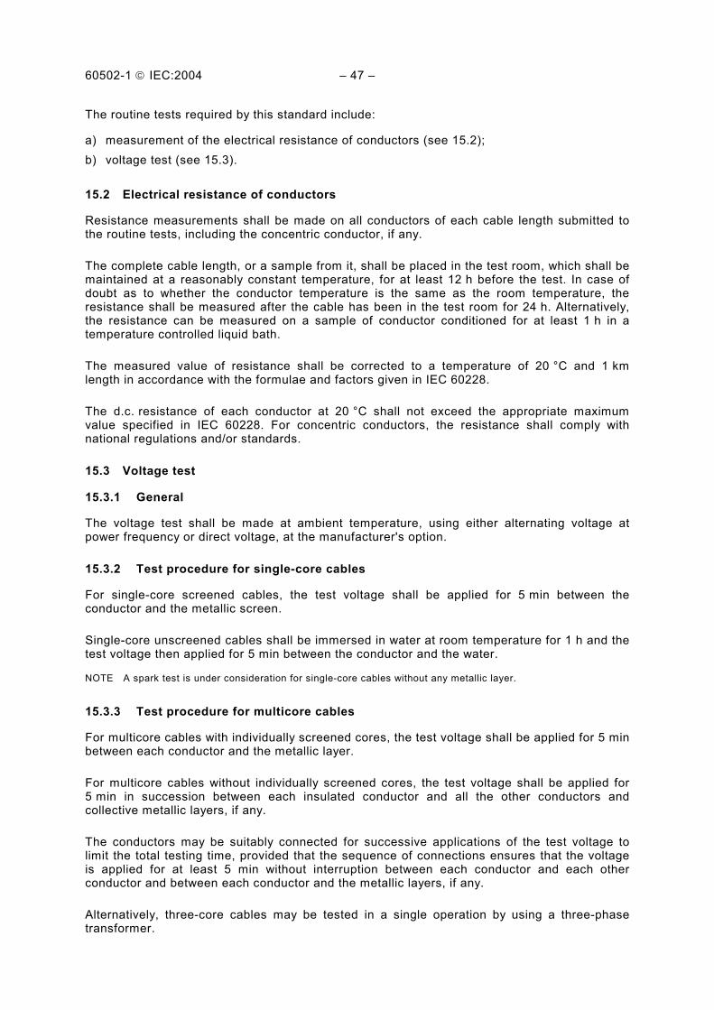
The routine tests required by this standard include:
a) measurement of the electrical resistance of conductors (see 15.2); b) voltage test (see 15.3).
15.2 Electrical resistance of conductors
Resistance measurements shall be made on all conductors of each cable length submitted to the routine tests, including the concentric conductor, if any.
The complete cable length, or a sample from it, shall be placed in the test room, which shall be maintained at a reasonably constant temperature, for at least 12 h before the test. In case of doubt as to whether the conductor temperature is the same as the room temperature, the resistance shall be measured after the cable has been in the test room for 24 h. Alternatively, the resistance can be measured on a sample of conductor conditioned for at least 1 h in a temperature controlled liquid bath.
The measured value of resistance shall be corrected to a temperature of 20 °C and 1 km length in accordance with the formulae and factors given in IEC 60228.
The d.c. resistance of each conductor at 20 °C shall not exceed the appropriate maximum value specified in IEC 60228. For concentric conductors, the resistance shall comply with national regulations and/or standards.
15.3 Voltage test
15.3.1 General
The voltage test shall be made at ambient temperature, using either alternating voltage at power frequency or direct voltage, at the manufacturer's option.
15.3.2 Test procedure for single-core cables
For single-core screened cables, the test voltage shall be applied for 5 min between the conductor and the metallic screen.
Single-core unscreened cables shall be immersed in water at room temperature for 1 h and the test voltage then applied for 5 min between the conductor and the water.
NOTE A spark test is under consideration for single-core cables without any metallic layer.
15.3.3 Test procedure for multicore cables
For multicore cables with individually screened cores, the test voltage shall be applied for 5 min between each conductor and the metallic layer.
For multicore cables without individually screened cores, the test voltage shall be applied for 5 min in succession between each insulated conductor and all the other conductors and collective metallic layers, if any.
The conductors may be suitably connected for successive applications of the test voltage to limit the total testing time, provided that the sequence of connections ensures that the voltage is applied for at least 5 min without interruption between each conductor and each other conductor and between each conductor and the metallic layers, if any.
Alternatively, three-core cables may be tested in a single operation by using a three-phase transformer.

60502-1 IEC:2004 49
15.3.4 Test voltage
The power frequency test voltage shall be 2,5 U0 + 2 kV. Values of single-phase test voltages for the standard rated voltages are given in Table 11.
Table 11 Routine test voltages
Rated voltage U0 kV 0,6 1,8
Test voltage kV 3,5 6,5
If, for three-core cables, the voltage test is carried out with a three-phase transformer, the test voltage between the phases shall be 1,73 times the values given in this table.
When a direct voltage is used, the applied voltage shall be 2,4 times the power frequency test voltage.
In all cases, the test voltage shall be increased gradually to the specified value.
15.3.5 Requirement
No breakdown of the insulation shall occur.
16 Sample tests
16.1 General
The sample tests required by this standard include:
a) conductor examination (see 16.4); b) check of dimensions (see 16.5 to 16.8); c) hot set test for EPR, HEPR and XLPE insulations and elastomeric sheaths (see 16.9).
16.2 Frequency of sample tests
16.2.1 Conductor examination and check of dimensions
Conductor examination, measurement of the thickness of insulation and sheath and measurement of the overall diameter shall be made on one length from each manufacturing series of the same type and nominal cross-section of cable, but shall be limited to not more than 10 % of the number of lengths in any contract.
16.2.2 Physical tests
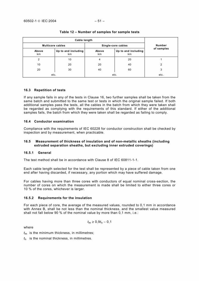
Physical tests shall be carried out on samples taken from manufactured cables according to agreed quality control procedures. In the absence of such an agreement, for contracts where the total length exceeds 2 km for multicore cables or 4 km for single-core cables, tests shall be made on the basis of Table 12.
60502-1 IEC:2004 51
Table 12 Number of samples for sample tests
Cable length
Multicore cables Single-core cables
Above km
Up to and includingkm
Above km
Up to and including km
Number of samples
2
10
20
10
20
30
4
20
40
20
40
60
1
2
3
etc. etc. etc.
16.3 Repetition of tests
If any sample fails in any of the tests in Clause 16, two further samples shall be taken from the same batch and submitted to the same test or tests in which the original sample failed. If both additional samples pass the tests, all the cables in the batch from which they were taken shall be regarded as complying with the requirements of this standard. If either of the additional samples fails, the batch from which they were taken shall be regarded as failing to comply.
16.4 Conductor examination
Compliance with the requirements of IEC 60228 for conductor construction shall be checked by inspection and by measurement, when practicable.
16.5 Measurement of thickness of insulation and of non-metallic sheaths (including extruded separation sheaths, but excluding inner extruded coverings)
16.5.1 General
The test method shall be in accordance with Clause 8 of IEC 60811-1-1.
Each cable length selected for the test shall be represented by a piece of cable taken from one end after having discarded, if necessary, any portion which may have suffered damage.
For cables having more than three cores with conductors of equal nominal cross-section, the number of cores on which the measurement is made shall be limited to either three cores or 10 % of the cores, whichever is larger.
16.5.2 Requirements for the insulation
For each piece of core, the average of the measured values, rounded to 0,1 mm in accordance with Annex B, shall be not less than the nominal thickness, and the smallest value measured shall not fall below 90 % of the nominal value by more than 0,1 mm, i.e.:
tm ≥ 0,9tn 0,1 where tm is the minimum thickness, in millimetres; tn is the nominal thickness, in millimetres.

60502-1 IEC:2004 53
16.5.3 Requirements for non-metallic sheaths
The piece of sheath shall comply with the following:
a) for unarmoured cables and cables with an oversheath not applied directly over armour, metallic screen or concentric conductor, the smallest value measured shall not fall below 85 % of the nominal value by more than 0,1 mm, i.e.:
tm ≥ 0,85tn 0,1
b) for an oversheath applied directly over armour, metallic screen or concentric conductor, and for a separation sheath, the smallest measured value shall not fall below 80 % of the nominal value by more than 0,2 mm, i.e.:
tm ≥ 0,8tn 0,2
16.6 Measurement of thickness of lead sheath
The minimum thickness of the lead sheath shall be determined by one of the following methods, at the discretion of the manufacturer, and shall not fall below 95 % of the nominal value by more than 0,1 mm, i.e.:
tm ≥ 0,95tn 0,1
16.6.1 Strip method
The measurement shall be made with a micrometer with plane faces of 4 mm to 8 mm diameter and an accuracy of ±0,01 mm.
The measurement shall be made on a test piece of sheath about 50 mm in length, removed from the completed cable. The piece shall be slit longitudinally and carefully flattened. After cleaning the test piece, a sufficient number of measurements shall be made along the circumference of the sheath and not less than 10 mm away from the edge of the flattened piece to ensure that the minimum thickness is measured.
16.6.2 Ring method
The measurements shall be made with a micrometer having either one flat nose and one ball nose, or one flat nose and a flat rectangular nose 0,8 mm wide and 2,4 mm long. The ball nose or the flat rectangular nose shall be applied to the inside of the ring. The accuracy of the micrometer shall be ±0,01 mm.
The measurements shall be made on a ring of the sheath carefully cut from the sample. The thickness shall be determined at a sufficient number of points around the circumference of the ring to ensure that the minimum thickness is measured.
16.7 Measurement of armour wires and tapes
16.7.1 Measurement on wires
The diameter of round wires and the thickness of flat wires shall be measured by means of a micrometer having two flat noses to an accuracy of ±0,01 mm. For round wires, two measure-ments shall be made at right angles to each other at the same position and the average of the two values taken as the diameter.

60502-1 IEC:2004 55
16.7.2 Measurement on tapes
The measurement shall be made with a micrometer having two flat noses of approximately 5 mm in diameter to an accuracy of ±0,01 mm. For tapes up to 40 mm in width, the thickness shall be measured at the centre of the width. For wider tapes the measurements shall be made 20 mm from each edge of the tape and the average of the results taken as the thickness.
16.7.3 Requirements
The dimensions of armour wires and tapes shall not fall below the nominal values given in 12.5 by more than:
5 % for round wires; 8 % for flat wires; 10 % for tapes.
16.8 Measurement of external diameter
If the measurement of the external diameter of the cable is required as a sample test, it shall be carried out in accordance with Clause 8 of IEC 60811-1-1.
16.9 Hot set test for EPR, HEPR and XLPE insulations and elastomeric sheaths
16.9.1 Procedure
The sampling and test procedure shall be carried out in accordance with Clause 9 of IEC 60811-2-1, employing the conditions given in Tables 17 and 22.
16.9.2 Requirements
The test results shall comply with the requirements given in Table 17 for EPR, HEPR and XLPE insulations, and in Table 22 for SE1 sheaths.
17 Type tests, electrical
A sample of completed cable, 10 m to 15 m in length, shall be subjected to the following tests, applied successively:
a) insulation resistance measurement at ambient temperature (see 17.1); b) insulation resistance measurement at maximum conductor temperature in normal operation
(see 17.2); c) voltage test for 4 h (see 17.3).
Cables of rated voltage 1,8/3 (3,6) kV shall also be subjected to an impulse test on a separate sample of completed cable, 10 m to 15 m in length (see 17.4).
The tests shall be limited to not more than three cores.

60502-1 IEC:2004 57
17.1 Insulation resistance measurement at ambient temperature
17.1.1 Procedure
This test shall be made on the sample length before any other electrical test.
All outer coverings shall be removed and the cores shall be immersed in water at ambient temperature for at least 1 h before the test.
The d.c. test voltage shall be between 80 V and 500 V and shall be applied for sufficient time to reach a reasonably steady measurement, but in any case for not less than 1 min and not more than 5 min.
The measurement shall be made between each conductor and the water.
If requested, measurement may be confirmed at a temperature of (20 ± 1) °C.
17.1.2 Calculations
The volume resistivity shall be calculated from the measured insulation resistance by the following formula:
ρ = 2 × × ×π l R
Ddln
where
ρ is the volume resistivity, in ohms · centimetres; R is the measured insulation resistance, in ohms; l is the length of the cable, in centimetres; D is the outer diameter of the insulation, in millimetres; d is the inner diameter of the insulation, in millimetres.
The "insulation resistance constant Ki" expressed in megohms ⋅ kilometres may also be calculated, using the formula:
ρ 0,367 10 = log
10 = 1111
i ×××× −−
dD
RlK
NOTE For the cores of shaped conductors, the ratio D/d is the ratio of the perimeter over the insulation to the perimeter over the conductor.
17.1.3 Requirements
The values calculated from the measurements shall be not less than those specified in Table 13.
17.2 Insulation resistance measurement at maximum conductor temperature
17.2.1 Procedure
The cores of the cable sample shall be immersed in water at a temperature within ±2 °C of the maximum conductor temperature in normal operation for at least 1 h before the test.

60502-1 IEC:2004 59
The d.c. test voltage shall be 80 V to 500 V and shall be applied for sufficient time to reach a reasonably steady measurement, but in any case for not less than 1 min and not more than 5 min.
The measurement shall be made between each conductor and the water.
17.2.2 Calculations
The volume resistivity and/or the insulation resistance constant shall be calculated from the insulation resistance by the formulae given in 17.1.2.
17.2.3 Requirements
The values calculated from the measurements shall be not less than those specified in Table 13.
17.3 Voltage test for 4 h
17.3.1 Procedure
The cores of the cable sample shall be immersed in water at ambient temperature for at least 1 h before the test.
A power frequency voltage equal to 4 U0 shall then be gradually applied and maintained continuously for 4 h between each conductor and the water.
17.3.2 Requirements
No breakdown of the insulation shall occur.
17.4 Impulse test for cables of rated voltage 1,8/3 (3,6) kV
17.4.1 Procedure
This test shall be performed on the sample at a conductor temperature between 5 °C and 10 °C above the maximum conductor temperature in normal operation.
The impulse voltage shall be applied according to the procedure given in IEC 60230 and shall have a peak value of 40 kV.
For multicore cables in which the cores are not individually screened, each series of impulses shall be applied in turn between each phase conductor and all the other conductors connected together and to earth.
17.4.2 Requirements
Each core of the cable shall withstand, without failure, 10 positive and 10 negative voltage impulses.
18 Type tests, non-electrical
The non-electrical type tests required by this standard are given in Table 14.

60502-1 IEC:2004 61
18.1 Measurement of thickness of insulation
18.1.1 Sampling
One sample shall be taken from each insulated cable core.
For cables having more than three cores with conductors of equal nominal cross-section, the number of cores on which the measurement is made shall be limited to either three cores or 10 % of the cores, whichever is larger.
18.1.2 Procedure
The measurements shall be made as described in 8.1 of IEC 60811-1-1.
18.1.3 Requirements
See 16.5.2.
18.2 Measurement of thickness of non-metallic sheaths (including extruded separation sheaths, but excluding inner coverings)
18.2.1 Sampling
One sample of cable shall be taken.
18.2.2 Procedure
The measurements shall be made as described in 8.2 of IEC 60811-1-1.
18.2.3 Requirements
See 16.5.3.
18.3 Tests for determining the mechanical properties of insulation before and after ageing
18.3.1 Sampling
Sampling and the preparation of the test pieces shall be carried out as described in 9.1 of IEC 60811-1-1.
18.3.2 Ageing treatments
The ageing treatments shall be carried out as described in 8.1 of IEC 60811-1-2 under the conditions specified in Table 15.
The tensile and bending tests after ageing with the copper conductor of Table 15 are only applicable to 0,6/1(1,2) kV cables. The bending test is only carried out on those cables for which the insulation cannot be subjected to the tensile test.
NOTE The tensile and bending tests, carried out after ageing in the presence of a copper conductor, are recommended. However, insufficient information has been obtained to date to make these requirements mandatory, except by agreement between the purchaser and the manufacturer.
18.3.3 Conditioning and mechanical tests
Conditioning and the measurement of mechanical properties shall be carried out as described in 9.1 of IEC 60811-1-1.

60502-1 IEC:2004 63
18.3.4 Requirements
The test results for aged and unaged test pieces shall comply with the requirements given in Table 15.
18.4 Tests for determining the mechanical properties of non-metallic sheaths before and after ageing
18.4.1 Sampling
Sampling and the preparation of the test pieces shall be carried out as described in 9.2 of IEC 60811-1-1.
18.4.2 Ageing treatments
The ageing treatments shall be carried out as described in 8.1 of IEC 60811-1-2, under the conditions specified in Table 18.
18.4.3 Conditioning and mechanical tests
Conditioning and the measurement of mechanical properties shall be carried out as described in 9.2 of IEC 60811-1-1.
18.4.4 Requirements
The test results for aged and unaged test pieces shall comply with the requirements given in Table 18.
18.5 Additional ageing test on pieces of completed cables
18.5.1 General
This test is intended to check that the insulation and non-metallic sheaths are not liable to deteriorate in operation due to contact with other components in the cable.
The test is applicable to cables of all types.
18.5.2 Sampling
Samples shall be taken from the completed cable as described in 8.1.4 of IEC 60811-1-2.
18.5.3 Ageing treatment
The ageing treatment of the pieces of cable shall be carried out in an air oven, as described in 8.1.4 of IEC 60811-1-2, under the following conditions:
temperature: (10 ± 2) °C above the maximum conductor temperature of the cable in normal operation (see Table 15);
duration: 7 × 24 h.
18.5.4 Mechanical tests
Test pieces of insulation and oversheath from the aged pieces of cable shall be prepared and subjected to mechanical tests as described in 8.1.4 of IEC 60811-1-2.

60502-1 IEC:2004 65
18.5.5 Requirements
The variations between the median values of tensile strength and elongation-at-break after ageing and the corresponding values obtained without ageing (see 18.3 and 18.4) shall not exceed the values applying to the test after ageing in an air oven specified in Table 15 for insulations, and Table 18 for non-metallic sheaths.
18.6 Loss of mass test on PVC sheaths of type ST2
18.6.1 Procedure
The sampling and test procedure shall be in accordance with 8.2 of IEC 60811-3-2.
18.6.2 Requirements
The test results shall comply with the requirements given in Table 19.
18.7 Pressure test at high temperature on insulations and non-metallic sheaths
18.7.1 Procedure
The pressure test at high temperature shall be carried out in accordance with Clause 8 of IEC 60811-3-1, employing the test conditions given in the test method and in Tables 16 and 20.
18.7.2 Requirements
The test results shall comply with the requirements given in Clause 8 of IEC 60811-3-1.
18.8 Test on PVC insulation and sheaths and halogen free sheaths at low temperatures
18.8.1 Procedure
The sampling and test procedures shall be in accordance with Clause 8 of IEC 60811-1-4, employing the test temperature specified in Tables 16, 19 and 21.
18.8.2 Requirements
The results of the test shall comply with the requirements given in Clause 8 of IEC 60811-1-4.
18.9 Test for resistance of PVC insulation and sheaths to cracking (heat shock test)
18.9.1 Procedure
The sampling and test procedure shall be in accordance with Clause 9 of IEC 60811-3-1, the test temperature and duration being in accordance with Tables 16 and 19.
18.9.2 Requirements
The results of the tests shall comply with the requirements given in Clause 9 of IEC 60811-3-1.

60502-1 IEC:2004 67
18.10 Ozone resistance test for EPR and HEPR insulations
18.10.1 Procedure
The sampling and test procedure shall be carried out in accordance with Clause 8 of IEC 60811-2-1. The ozone concentration and test duration shall be in accordance with Table 17.
18.10.2 Requirements
The results of the test shall comply with the requirements given in Clause 8 of IEC 60811-2-1.
18.11 Hot set test for EPR, HEPR and XLPE insulations and elastomeric sheaths
The sampling and test procedure shall be carried out in accordance with 16.9 and shall comply with its requirements.
18.12 Oil immersion test for elastomeric sheaths
18.12.1 Procedure
The sampling and test procedure shall be carried out in accordance with Clause 10 of IEC 60811-2-1, employing the conditions given in Table 22.
18.12.2 Requirements
The results of the test shall comply with the requirements given in Table 22.
18.13 Water absorption test on insulation
18.13.1 Procedure
The sampling and test procedure shall be carried out in accordance with 9.1 or 9.2 of IEC 60811-1-3, employing the conditions specified in Tables 16 or 17, respectively.
18.13.2 Requirements
The results of the test shall comply with the requirements specified in 9.1 of IEC 60811-1-3 or Table 17, respectively.
18.14 Fire tests
18.14.1 Flame spread test on single cables
This test shall be carried out on ST1, ST2, or SE1 oversheathed cables only when specially required.
The test method and requirements shall be those specified in IEC 60332-1.
18.14.2 Flame spread test on bunched cables
This test shall be carried out on ST8 oversheathed halogen free cables.
The test method and requirements shall be those specified in IEC 60332-3-24.

60502-1 IEC:2004 69
18.14.3 Smoke emission test
This test shall be carried out on ST8 oversheathed halogen free cables.
The test method and requirements shall be those specified in IEC 61034-2.
18.14.4 Acid gas emission test
This test shall be carried out on the non-metallic components of ST8 oversheathed halogen free cables.
18.14.4.1 Procedure
The test method shall be that specified in IEC 60754-1.
18.14.4.2 Requirements
The results of the test shall comply with the requirements of Table 23.
18.14.5 pH and conductivity test
This test shall be carried out on the non-metallic components of ST8 oversheathed halogen free cables.
18.14.5.1 Procedure
The test method shall be that specified in IEC 60754-2.
18.14.5.2 Requirements
The results of the test shall comply with the requirements of Table 23.
18.14.6 Fluorine content test
This test shall be carried out on the non-metallic components of ST8 oversheathed halogen free cables.
18.14.6.1 Procedure
The test method shall be that specified in IEC 60684-2.
18.14.6.2 Requirements
The results of the test shall comply with the requirements of Table 23.
18.14.7 Toxicity test
Under consideration.
NOTE A test method is under development within IEC.
18.15 Measurement of carbon black content of black PE oversheaths
18.15.1 Procedure
The sampling and test procedure shall be carried out in accordance with Clause 11 of IEC 60811-4-1.

60502-1 IEC:2004 71
18.15.2 Requirements
The results of the test shall comply with the requirements of Table 20.
18.16 Shrinkage test for XLPE insulation
18.16.1 Procedure
The sampling and test procedure shall be carried out in accordance with Clause 10 of IEC 60811-1-3 under the conditions specified in Table 17.
18.16.2 Requirements
The results of the test shall comply with the requirements of Table 17.
18.17 Special bending test
This test shall be made on multicore cables with rated voltage 0,6/1 (1,2) kV, having a collective metallic layer in the form of metallic tapes applied directly over the assembled cores and omitting the inner covering.
18.17.1 Procedure
The sample shall be bent around a test cylinder (for example, the hub of a drum) at ambient temperature for at least one complete turn. The diameter of the cylinder shall be 7 D ± 5 % where D is the actual external diameter of the cable sample. The cable shall then be unwound and the process shall be repeated except that the bending of the sample shall be in the reverse direction.
This cycle of operations shall be carried out three times. The sample, left bent around the cylinder shall then be placed in an air oven heated to the maximum conductor temperature in normal operation of the cable for 24 h.
After the cable has cooled down, and while it is still bent, the voltage test shall be carried out in accordance with 15.3.
18.17.2 Requirements
No breakdown shall occur and the oversheath shall show no sign of cracking.
18.18 Determination of hardness of HEPR insulation
18.18.1 Procedure
The sampling and test procedure shall be carried out in accordance with Annex C.
18.18.2 Requirements
The results of the test shall comply with the requirements of Table 17.
18.19 Determination of the elastic modulus of HEPR insulation
18.19.1 Procedure
Sampling, preparation of the test pieces and the test procedure shall be carried out in accordance with Clause 9 of IEC 60811-1-1.
60502-1 IEC:2004 73
The loads required for 150 % elongation shall be measured. The corresponding stresses shall be calculated by dividing the loads measured by the cross-sectional areas of the unstretched test pieces. The ratios of the stresses to strains shall be determined to obtain the elastic moduli at 150 % elongation.
The elastic modulus shall be the median value.
18.19.2 Requirements
The results of the test shall comply with the requirements of Table 17.
18.20 Shrinkage test for PE oversheaths
18.20.1 Procedure
The sampling and test procedure shall be carried out in accordance with Clause 11 of IEC 60811-1-3 under the conditions specified in Table 20.
18.20.2 Requirements
The results of the test shall comply with the requirements of Table 20.
NOTE For halogen free oversheaths, the test method is under consideration.
18.21 Additional mechanical tests on halogen free oversheaths
These tests are intended to check that the halogen free oversheaths are not liable to damage during installation and operation.
NOTE Abrasion, tear resistance and heat shock tests are under consideration.
18.22 Water absorption test for halogen free oversheaths
18.22.1 Procedure
The sampling and test procedure shall be carried out in accordance with 9.2 of IEC 60811-1-3 employing the conditions specified in Table 21.
18.22.2 Requirements
The results of the test shall comply with the requirements of Table 21.
19 Electrical tests after installation
Tests after installation are made, if required, when the installation of the cable and its accessories has been completed.
A d.c. voltage equal to 4 U0 shall be applied for 15 min.
NOTE Electrical tests on repaired installations are subject to installation requirements. The above test is for new installations only.

60502-1 IEC:2004 75
Table 13 Electrical type test requirements for insulating compounds
Designation of compounds (see 4.2)
Unit PVC/A EPR/ HEPR
XLPE
Maximum conductor temperature in normal operation (see 4.2)
°C 70 90 90
Volume resistivity ρ
at 20 °C (see 17.1) at maximum conductor temperature in normal operation (see 17.2)
Ω·cm Ω·cm
1013 1010
1012
1012
Insulation resistance constant K i
at 20 °C (see 17.1) at maximum conductor temperature in normal operation (see 17.2)
MΩ·km MΩ·km
36,7 0,037
3,67
3,67

60502-1 IEC:2004 77
Table 14 Non-electrical type tests (see Tables 15 to 23)
Insulations Sheaths
PVC/A EPR HEPR XLPE PVC PE Designation of compounds (see 4.2 and 4.3)
ST1 ST2 ST3 ST7 ST8 SE1
Dimensions
Measurements of thickness x x x x x x x x x x
Mechanical properties (tensile strength and elongation-at-break)
Without ageing x x x x x x x x x x
After ageing in air oven x x x x x x x x x x
After ageing of pieces of complete cable x x x x x x x x x x
After immersion in hot oil x
Thermoplastic properties
Hot pressure test (indentation) x x x x x
Behaviour at low temperature x x x x
Miscellaneous
Loss of mass in air oven x
Heat shock test (cracking) x x x
Ozone resistance test x x
Hot set test x x x x
Water absorption x x x x x
Shrinkage test x x x c
Carbon black content a x x
Determination of hardness x
Determination of elastic modulus x
Fire tests
Flame spread test on single cables (if required)
x x x
Flame spread test on bunched cables x
Smoke emission test on cables x
Acid gas emission test b b b x
pH and conductivity b b b − x
Fluorine content test − b b b − − − − x −
NOTE x indicates that the type test is to be applied. a For black oversheaths only. b Indicates that the test is only required for EPR, HEPR and XLPE when the cable is claimed to be halogen free. c Under consideration.

60502-1 IEC:2004 79
Table 15 Test requirements for mechanical characteristics of insulating compounds (before and after ageing)
Unit PVC/A EPR HEPR XLPE
Designation of compounds (see 4.2)
0,6/1(1,2) kV cables
with copper
conductors
All othercables
0,6/1(1,2) kVcables
with copper
con ductors
All other cables
0,6/1(1,2) kVcables
with copper
con ductors
All other
cables
Maximum conductor temperature in normal operation (see 4.2)
°C 70 90 90 90 90 90 90
Without ageing (IEC 60811-1-1, Subclause 9.1)
Tensile strength, minimum N/mm2 12,5 4,2 4,2 8,5 8,5 12,5 12,5
Elongation-at-break, minimum % 150 200 200 200 200 200 200
After ageing in an air oven (IEC 60811-1-2, Subclause 8.1)
After ageing without conductor
Treatment:
temperature tolerance duration
°C °C h
100 ±2
168
135 ±3
168
135 ±3
168
135 ±3
168
135 ±3
168
135 ±3
168
135 ±3
168
Tensile strength
a) value after ageing, minimum b) variation a, maximum
N/mm2 %
12,5±25
±30
±30
±30
±30
±25
±25
Elongation-at-break:
a) value after ageing, minimum b) variation a, maximum
% %
150 ±25
±30
±30
±30
±30
±25
±25
After ageing with copper conductor followed by the tensile test b
Treatment:
temperature tolerance duration
°C °C h
150 ±3
168
150 ±3
168
150 ±3
168
Tensile strength:
Variation a, maximum % ±30 ±30 ±30
Elongation-at-break:
Variation a, maximum % ±30 ±30 ±30
After ageing with copper conductor followed by bending test (only if the tensile test is not practicable) b
Treatment:
temperature tolerance duration
°C °C h
150 ±3
240
150 ±3
240
150 ±3
240
Results to be obtained No cracks
No cracks
No cracks
a Variation: difference between the median value obtained after ageing and the median value obtained without ageing expressed as a percentage of the latter.
b See 18.3.2.

60502-1 IEC:2004 81
Table 16 Test requirements for particular characteristics for PVC insulating compound
Designation of compound (see 4.2 and 4.3) Unit PVC/A
Use of the PVC compound Insulation
Pressure test at high temperature (IEC 60811-3-1, Clause 8)
temperature (tolerance ±2 °C) °C 80
Behaviour at low temperature a (IEC 60811-1-4, Clause 8)
Test to be carried out without previous ageing:
cold bending test for diameter <12,5 mm temperature (tolerance ±2 °C)
°C
15
Cold elongation test on dumb-bells:
temperature (tolerance ±2 °C) °C 15
Cold impact test:
temperature (tolerance ±2 °C) °C
Heat shock test (IEC 60811-3-1, Clause 9)
Treatment:
temperature (tolerance ±3 °C) duration
°C h
150 1
Water absorption (IEC 60811-1-3, Subclause 9.1)
Electrical method:
Treatment:
temperature (tolerance ±2 °C) duration
°C h
70 240
a Due to climatic conditions, national standards may require the use of a lower temperature.
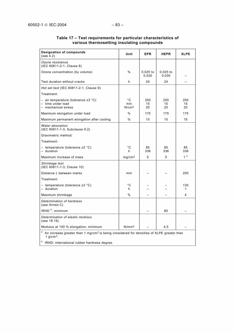
60502-1 IEC:2004 83
Table 17 Test requirements for particular characteristics of various thermosetting insulating compounds
Designation of compounds (see 4.2) Unit EPR HEPR XLPE
Ozone resistance (IEC 60811-2-1, Clause 8)
Ozone concentration (by volume) % 0,025 to0,030
0,025 to 0,030
Test duration without cracks h 24 24
Hot set test (IEC 60811-2-1, Clause 9)
Treatment:
air temperature (tolerance ±3 °C) time under load mechanical stress
°C min
N/cm2
250 15 20
250 15 20
200 15 20
Maximum elongation under load % 175 175 175
Maximum permanent elongation after cooling % 15 15 15
Water absorption (IEC 60811-1-3, Subclause 9.2)
Gravimetric method:
Treatment:
temperature (tolerance ±2 °C) duration
°C h
85 336
85 336
85 336
Maximum increase of mass mg/cm2 5 5 1 a
Shrinkage test (IEC 60811-1-3, Clause 10)
Distance L between marks mm 200
Treatment:
temperature (tolerance ±3 °C) duration
°C h
130 1
Maximum shrinkage % 4
Determination of hardness (see Annex C)
IRHD b, minimum 80
Determination of elastic modulus (see 18.19)
Modulus at 150 % elongation, minimum N/mm2 4,5 a An increase greater than 1 mg/cm2 is being considered for densities of XLPE greater than 1 g/cm3. b IRHD: international rubber hardness degree.
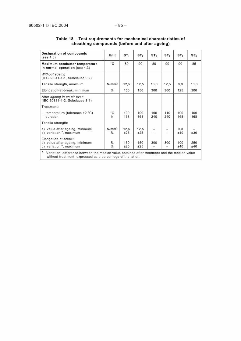
60502-1 IEC:2004 85
Table 18 Test requirements for mechanical characteristics of sheathing compounds (before and after ageing)
Designation of compounds (see 4.3) Unit ST1 ST2 ST3 ST7 ST8 SE1
Maximum conductor temperature in normal operation (see 4.3)
°C 80 90 80 90 90 85
Without ageing (IEC 60811-1-1, Subclause 9.2)
Tensile strength, minimum N/mm2 12,5 12,5 10,0 12,5 9,0 10,0
Elongation-at-break, minimum % 150 150 300 300 125 300
After ageing in an air oven (IEC 60811-1-2, Subclause 8.1)
Treatment:
temperature (tolerance ±2 °C) duration
°C h
100 168
100 168
100 240
110240
100 168
100 168
Tensile strength:
a) value after ageing, minimum b) variation a, maximum
N/mm2
% 12,5±25
12,5±25
9,0 ±40
±30
Elongation-at-break: a) value after ageing, minimum b) variation a, maximum
% %
150 ±25
150 ±25
300
300
100 ±40
250 ±40
a Variation: difference between the median value obtained after treatment and the median value without treatment, expressed as a percentage of the latter.

60502-1 IEC:2004 87
Table 19 Test requirements for particular characteristics for PVC sheathing compounds
Designation of compound (see 4.2 and 4.3) Unit ST1 ST2
Use of the PVC compound Sheath
Loss of mass in an air oven (IEC 60811-3-2, Subclause 8.2)
Treatment:
temperature (tolerance ±2 °C) duration
°C h
100 168
Maximum loss of mass mg/cm2 1,5
Pressure test at high temperature (IEC 60811-3-1, Clause 8)
- temperature (tolerance ±2 °C) °C 80 90
Behaviour at low temperature a (IEC 60811-1-4, Clause 8)
Test to be carried out without previous ageing:
cold bending test for diameter <12,5 mm temperature (tolerance ±2 °C)
°C
15
15
Cold elongation test on dumb-bells:
temperature (tolerance ±2 °C) °C 15 15
Cold impact test:
temperature (tolerance ±2 °C) °C 15 15
Heat shock test (IEC 60811-3-1, Clause 9)
Treatment:
temperature (tolerance ±3 °C) duration
°C h
150 1
150 1
a Due to climatic conditions national standards may require the use of a lower temperature.

60502-1 IEC:2004 89
Table 20 Test requirements for particular characteristics of thermoplastic PE sheathing compounds
Designation of compounds (see 4.3) Unit ST3 ST7
Density a (IEC 60811-1-3, Clause 8)
Carbon black content (for black oversheaths only) (IEC 60811-4-1, Clause 11)
Nominal value % 2,5 2,5
Tolerance % ±0,5 ±0,5
Shrinkage test (IEC 60811-1-3, Clause 11)
Treatment:
temperature (tolerance ±2 °C) heating, duration heating, cycles
°C h
80 5 5
80 5 5
Maximum shrinkage % 3 3
Pressure test at high temperature (IEC 60811-3-1, Subclause 8.2)
temperature (tolerance ±2 °C) °C 110 a The measurement of density is only required for the purpose of other tests.

60502-1 IEC:2004 91
Table 21 Test requirements for particular characteristics of halogen free sheathing compound
Designation of compound Unit ST8
Behaviour at low temperature a (IEC 60811-1-4, Clause 8)
Test to be carried out without previous ageing:
cold bending test for diameter <12,5 mm temperature (tolerance ±2 °C)
°C
-15
Cold elongation test on dumb-bells:
temperature (tolerance ±2 °C) °C -15
Cold impact test:
temperature (tolerance ±2 °C) °C -15
Pressure test at high temperature (IEC 60811-3-1, Clause 8)
temperature (tolerance ±2 °C) °C 80
Water absorption (IEC 60811-1-3, Subclause 9.2)
Gravimetric method:
Treatment:
temperature (tolerance ±2 °C) duration
°C h
70 24
Maximum increase of mass mg/cm2 10
a Due to climatic conditions, national standards may require the use of a lower temperature.

60502-1 IEC:2004 93
Table 22 Test requirements for particular characteristics of elastomeric sheathing compound
Designation of compound (see 4.3) Unit SE1
Oil immersion test followed by a determination of the mechanical properties (IEC 60811-2-1, Clause 10 and IEC 60811-1-1, Clause 9)
Treatment:
oil temperature (tolerance ±2 °C) duration
°C h
100 24
Maximum variation a of:
a) tensile strength b) elongation-at-break
% %
±40 ±40
Hot set test (IEC 60811-2-1, Clause 9)
Treatment: temperature (tolerance ±3 °C) time under load mechanical stress
°C min
N/cm2
200 15 20
Maximum elongation under load % 175
Maximum permanent elongation after cooling % 15 a Variation: difference between the median value obtained after treatment and the median value without treatment, expressed as a percentage of the latter.
Table 23 Test methods and requirements for halogen free compounds
Test method Unit Requirement
Acid gas emission test (IEC 60754-1)
Bromine and chlorine content (expressed as HCl), maximum % 0,5
Fluorine content test (IEC 60684-2)
Fluorine content, maximum % 0,1
pH and conductivity test (IEC 60754-2)
pH, minimum Conductivity, maximum
µS/mm
4,3 10
NOTE A toxicity test is under consideration.

60502-1 IEC:2004 95
Annex A (normative)
Fictitious calculation method for determination of dimensions
of protective coverings
The thickness of cable coverings, such as sheaths and armour, has usually been related to nominal cable diameters by means of "step-tables".
This sometimes causes problems. The calculated nominal diameters are not necessarily the same as the actual values achieved in production. In borderline cases, queries can arise if the thickness of a covering does not correspond to the actual diameter because the calculated diameter is slightly different. Variations in shaped conductor dimensions between manufacturers and different methods of calculation cause differences in nominal diameters and may therefore lead to variations in the thicknesses of coverings used on the same basic design of cable.
To avoid these difficulties, the fictitious calculation method shall be used. The idea is to ignore the shape and degree of compaction of conductors and to calculate fictitious diameters from formulae based on the cross-sectional area of conductors, nominal insulation thickness and number of cores. Thicknesses of sheath and other coverings are then related to the fictitious diameters by formulae or by tables. The method of calculating fictitious diameters is precisely specified and there is no ambiguity about the thicknesses of coverings to be used, which are independent of slight differences in manufacturing practices. This standardizes cable designs, thicknesses being pre-calculated and specified for each conductor cross-section.
The fictitious calculation is used only to determine dimensions of sheaths and cable coverings. It is not a replacement for the calculation of actual diameters required for practical purposes, which should be calculated separately.
A.1 General
The following fictitious method of calculating thicknesses of various coverings in a cable has been adopted to ensure that any differences which can arise in independent calculations, for example due to the assumption of conductor dimensions and the unavoidable differences between nominal and actually achieved diameters, are eliminated.
All thickness values and diameters shall be rounded according to the rules in Annex B to the first decimal figure.
Holding strips, for example counter helix over armour, if not thicker than 0,3 mm, are neglected in this calculation method.
A.2 Method
A.2.1 Conductors
The fictitious diameter (dL) of a conductor, irrespective of shape and compactness, is given for each nominal cross-section in Table A.1.
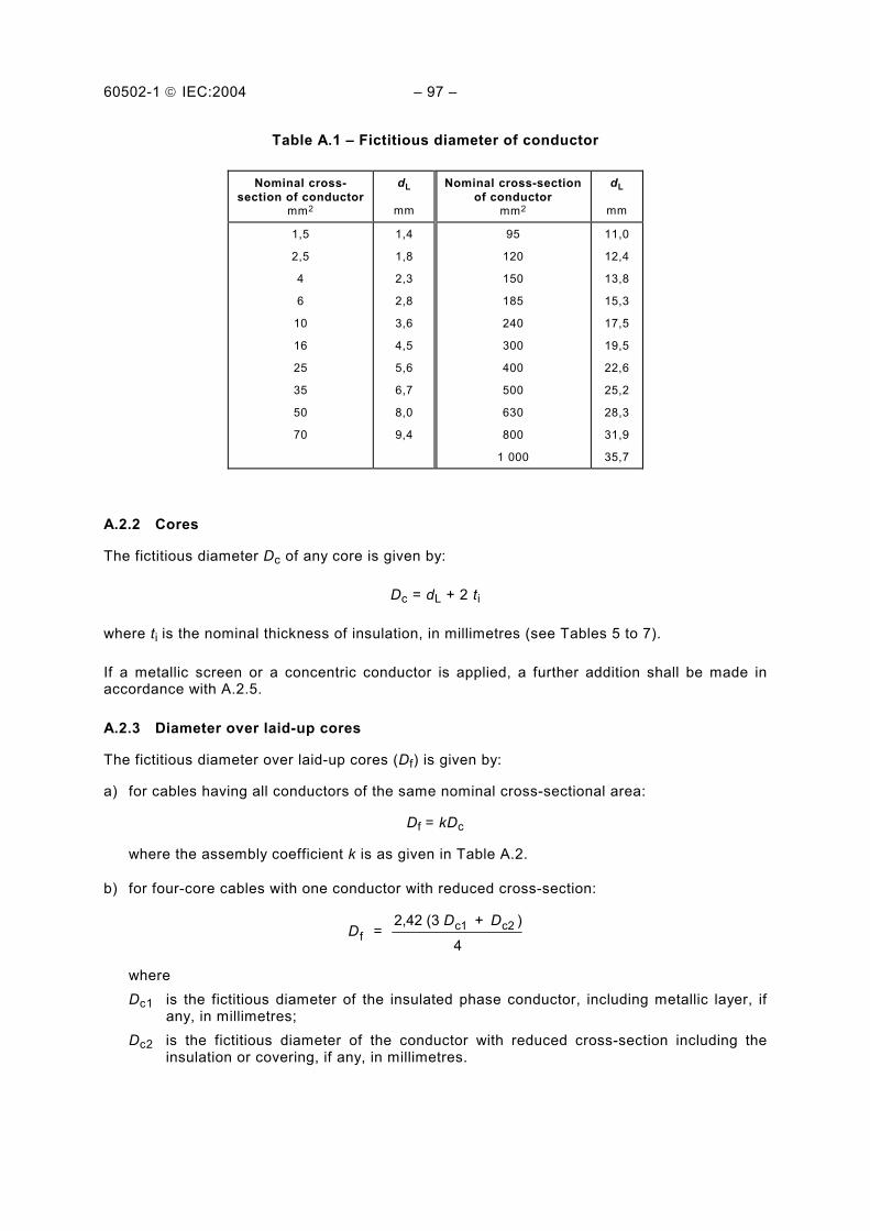
60502-1 IEC:2004 97
Table A.1 Fictitious diameter of conductor
Nominal cross-section of conductor
mm2
dL
mm
Nominal cross-section of conductor
mm2
dL
mm
1,5
2,5
4
6
10
16
25
35
50
70
1,4
1,8
2,3
2,8
3,6
4,5
5,6
6,7
8,0
9,4
95
120
150
185
240
300
400
500
630
800
1 000
11,0
12,4
13,8
15,3
17,5
19,5
22,6
25,2
28,3
31,9
35,7
A.2.2 Cores
The fictitious diameter Dc of any core is given by:
Dc = dL + 2 ti
where ti is the nominal thickness of insulation, in millimetres (see Tables 5 to 7).
If a metallic screen or a concentric conductor is applied, a further addition shall be made in accordance with A.2.5.
A.2.3 Diameter over laid-up cores
The fictitious diameter over laid-up cores (Df) is given by:
a) for cables having all conductors of the same nominal cross-sectional area:
Df = kDc
where the assembly coefficient k is as given in Table A.2.
b) for four-core cables with one conductor with reduced cross-section:
DD D
f = 2,42 (3 + )c1 c2
4
where Dc1 is the fictitious diameter of the insulated phase conductor, including metallic layer, if
any, in millimetres; Dc2 is the fictitious diameter of the conductor with reduced cross-section including the
insulation or covering, if any, in millimetres.

60502-1 IEC:2004 – 99 –
Table A.2 – Assembly coefficient k for laid-up cores
Number of cores
Assembly coefficient
k
Number of cores
Assembly coefficient
k
2
3
4
5
6
7
7 a
8
8 a
9
9 a
10
10 a
11
12
12 a
13
14
15
16
17
18
18*
19
20
21
22
23
2,00
2,16
2,42
2,70
3,00
3,00
3,35
3,45
3,66
3,80
4,00
4,00
4,40
4,00
4,16
5,00
4,41
4,41
4,70
4,70
5,00
5,00
7,00
5,00
5,33
5,33
5,67
5,67
24
25
26
27
28
29
30
31
32
33
34
35
36
37
38
39
40
41
42
43
44
45
46
47
48
52
61
6,00
6,00
6,00
6,15
6,41
6,41
6,41
6,70
6,70
6,70
7,00
7,00
7,00
7,00
7,33
7,33
7,33
7,67
7,67
7,67
8,00
8,00
8,00
8,00
8,15
8,41
9,00
a Cores assembled in one layer.
A.2.4 Inner coverings
The fictitious diameter over the inner covering (DB) is given by:
DB = Df + 2 tB
where tB = 0,4 mm for fictitious diameters over laid-up cores (Df) up to and including 40 mm; tB = 0,6 mm for Df exceeding 40 mm.
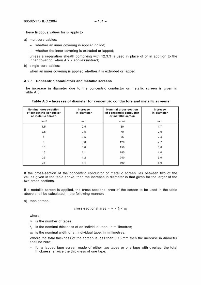
60502-1 IEC:2004 101
These fictitious values for tB apply to
a) multicore cables: whether an inner covering is applied or not; whether the inner covering is extruded or lapped;
unless a separation sheath complying with 12.3.3 is used in place of or in addition to the inner covering, when A.2.7 applies instead;
b) single-core cables: when an inner covering is applied whether it is extruded or lapped.
A.2.5 Concentric conductors and metallic screens
The increase in diameter due to the concentric conductor or metallic screen is given in Table A.3.
Table A.3 Increase of diameter for concentric conductors and metallic screens
Nominal cross-section of concentric conductor
or metallic screen
Increase in diameter
Nominal cross-section of concentric conductor
or metallic screen
Increase in diameter
mm2 mm mm2 mm
1,5
2,5
4
6
10
16
25
35
0,5
0,5
0,5
0,6
0,8
1,1
1,2
1,4
50
70
95
120
150
185
240
300
1,7
2,0
2,4
2,7
3,0
4,0
5,0
6,0
If the cross-section of the concentric conductor or metallic screen lies between two of the values given in the table above, then the increase in diameter is that given for the larger of the two cross-sections.
If a metallic screen is applied, the cross-sectional area of the screen to be used in the table above shall be calculated in the following manner:
a) tape screen:
cross-sectional area = nt × tt × wt
where nt is the number of tapes; tt is the nominal thickness of an individual tape, in millimetres; wt is the nominal width of an individual tape, in millimetres.
Where the total thickness of the screen is less than 0,15 mm then the increase in diameter shall be zero: for a lapped tape screen made of either two tapes or one tape with overlap, the total
thickness is twice the thickness of one tape;

60502-1 IEC:2004 103
for a longitudinally applied tape screen: if the overlap is below 30 %, the total thickness is the thickness of the tape; if the overlap is greater than or equal to 30 %, the total thickness is twice the
thickness of the tape;
b) wire screen (with a counter helix, if any):
cross sectional area- =
4 + w w
2
h h hn d
n t w× ×
× ×π
where nw is the number of wires; dw is the diameter of an individual wire, in millimetres; nh is the number of counter helix; th is the thickness of counter helix, in millimetres, if greater than 0,3 mm; wh is the width of counter helix, in millimetres.
A.2.6 Lead sheath
The fictitious diameter over the lead sheath (Dpb) is given by:
Dpb = Dg + 2 tpb
where Dg is the fictitious diameter under the lead sheath, in millimetres; tpb is the thickness calculated in accordance with Clause 11, in millimetres.
A.2.7 Separation sheath
The fictitious diameter over the separation sheath (Ds) is given by:
Ds = Du + 2 ts
where Du is the fictitious diameter under the separation sheath, in millimetres; ts is the thickness calculated in accordance with 12.3.3, in millimetres.
A.2.8 Lapped bedding
The fictitious diameter over the lapped bedding (Dlb) is given by:
Dlb = Dulb + 2 tlb
where Dulb is the fictitious diameter under the lapped bedding, in millimetres; tlb is the thickness of lapped bedding, i.e. 1,5 mm according to 12.3.4.

60502-1 IEC:2004 105
A.2.9 Additional bedding for tape-armoured cables (provided over the inner covering)
Table A.4 Increase of diameter for additional bedding
Fictitious diameter under the additional bedding
Above mm
Up to and including mm
Increase in diameter for additional bedding
mm
29
29
1,0
1,6
A.2.10 Armour
The fictitious diameter over the armour (Dx) is given for
a) flat or round wire armour by:
Dx = DA + 2 tA + 2 tw
where DA is the diameter under the armour, in millimetres; tA is the thickness or diameter of the armour wire, in millimetres; tw is the thickness of the counter helix, if any, in millimetres, if greater than 0,3 mm.
b) double tape armour by:
Dx = DA + 4 tA
where DA is the diameter under the armour, in millimetres; tA is the thickness of the armour tape, in millimetres.

60502-1 IEC:2004 107
Annex B (normative)
Rounding of numbers
B.1 Rounding of numbers for the purpose of the fictitious calculation method
The following rules apply when rounding numbers in calculating fictitious diameters and determining dimensions of component layers in accordance with Annex A.
When the calculated value at any stage has more than one decimal place, the value shall be rounded to one decimal place, i.e. to the nearest 0,1 mm. The fictitious diameter at each stage shall be rounded to 0,1 mm and, when used to determine the thickness or dimension of an overlying layer, it shall be rounded before being used in the appropriate formula or table. The thickness calculated from the rounded value of the fictitious diameter shall in turn be rounded to 0,1 mm as required in Annex A.
To illustrate these rules, the following practical examples are given:
a) when the figure in the second decimal place before rounding is 0, 1, 2, 3 or 4, then the figure retained in the first decimal place remains unchanged (rounding down).
Examples: 2,12 ≈ 2,1 2,449 ≈ 2,4 25,0478 ≈ 25,0
b) when the figure in the second decimal place before rounding is 9, 8, 7, 6 or 5, then the figure in the first decimal place is increased by one (rounding up).
Examples: 2,17 ≈ 2,2 2,453 ≈ 2,5 30,050 ≈ 30,1
B.2 Rounding of numbers for other purposes
For purposes other than those considered under Clause B.1, it may be required that values are rounded to more than one decimal place. This may occur, for instance, in calculating the average value of several measurement results, or the minimum value by applying a percentage tolerance to a given nominal value. In these cases, rounding shall be carried out to the number of decimal places specified in the relevant clauses.
The method of rounding shall then be as follows:
a) if the last figure to be retained is followed, before rounding, by 0, 1, 2, 3 or 4, it shall remain unchanged (rounding down);
b) if the last figure to be retained is followed, before rounding, by 9, 8, 7, 6 or 5, it shall be increased by one (rounding up).

60502-1 IEC:2004 109
Examples:
2,449 ≈ 2,45 rounded to two decimal places
2,449 ≈ 2,4 rounded to one decimal place
25,0478 ≈ 25,048 rounded to three decimal places
25,0478 ≈ 25,05 rounded to two decimal places
25,0478 ≈ 25,0 rounded to one decimal place

60502-1 IEC:2004 111
Annex C (normative)
Determination of hardness of HEPR insulations
C.1 Test piece
The test piece shall be a sample of completed cable with all the coverings, external to the HEPR insulation to be measured, carefully removed. Alternatively, a sample of insulated core may be used.
C.2 Test procedure
Tests shall be made in accordance with ISO 48 with exceptions as indicated below.
C.2.1 Surfaces of large radius of curvature
The test instrument, in accordance with ISO 48, shall be constructed so as to rest firmly on the HEPR insulation and permit the presser foot and indentor to make vertical contact with this surface. This is done in one of the following ways:
a) the instrument is fitted with feet moveable in universal joints so that they adjust themselves to the curved surface;
b) the base of the instrument is fitted with two parallel rods A and A', their distance apart depending on the curvature of the surface (see Figure C.1).
These methods may be used on surfaces with radius of curvature down to 20 mm.
When the thickness of HEPR insulation tested is less than 4 mm, an instrument as described in the method used in ISO 48 for thin and small test pieces shall be used.
C.2.2 Surfaces of small radius of curvature
On surfaces with too small a radius of curvature for the procedures described in C.2.1, the test piece shall be supported on the same rigid base as the test instrument, in such a way as to minimize bodily movement of the HEPR insulation when the indenting force increment is applied to the indentor and so that the indentor is vertically above the axis of the test piece. Suitable procedures are as follows:
a) rest the test piece in a grove or trough in a metal jig (see Figure C.2a); b) rest the ends of the conductor of the test piece in V-blocks (see Figure C.2b).
The smallest radius of curvature of the surface to be measured by these methods shall be at least 4 mm.
For smaller radii, an instrument as described in the method used in ISO 48 for thin and small test pieces shall be used.

60502-1 IEC:2004 113
C.2.3 Conditioning and test temperature
The minimum time between manufacture, i.e. vulcanization, and testing shall be 16 h.
The test shall be carried out at a temperature of (20 ± 2) °C and the test pieces shall be maintained at this temperature for at least 3 h immediately before testing.
C.2.4 Number of measurements
One measurement shall be made at each of three or five different points distributed around the test piece. The median of the results shall be taken as the hardness of the test piece, expressed to the nearest whole number in international rubber hardness degrees (IRHD).
Figure C.1 Test on surfaces of large radius of curvature

60502-1 IEC:2004 115
Figure C.2a Test piece groove Figure C.2b Test piece in V-blocks
Figure C.2 Test on surfaces of small radius of curvature
___________

Standards Survey
The IEC would like to offer you the best quality standards possible. To make sure that wecontinue to meet your needs, your feedback is essential. Would you please take a minuteto answer the questions overleaf and fax them to us at +41 22 919 03 00 or mail them tothe address below. Thank you!
Customer Service Centre (CSC)
International Electrotechnical Commission3, rue de Varembé1211 Genève 20Switzerland
or
Fax to: IEC/CSC at +41 22 919 03 00
Thank you for your contribution to the standards-making process.
Non affrancareNo stamp required
Nicht frankierenNe pas affranchir
A Prioritaire
RÉPONSE PAYÉE
SUISSE
Customer Service Centre (CSC)International Electrotechnical Commission3, rue de Varembé1211 GENEVA 20Switzerland
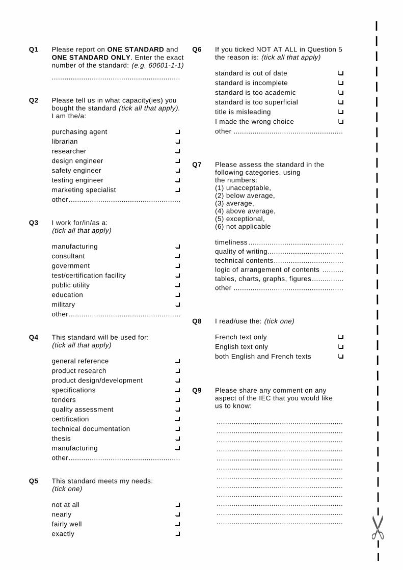
Q1 Please report on ONE STANDARD andONE STANDARD ONLY . Enter the exactnumber of the standard: (e.g. 60601-1-1)
.............................................................
Q2 Please tell us in what capacity(ies) youbought the standard (tick all that apply).I am the/a:
purchasing agent R
librarian R
researcher R
design engineer R
safety engineer R
testing engineer R
marketing specialist R
other.....................................................
Q3 I work for/in/as a:(tick all that apply)
manufacturing R
consultant R
government R
test/certification facility R
public utility R
education R
military R
other.....................................................
Q4 This standard will be used for:(tick all that apply)
general reference R
product research R
product design/development R
specifications R
tenders R
quality assessment R
certification R
technical documentation R
thesis R
manufacturing R
other.....................................................
Q5 This standard meets my needs:(tick one)
not at all R
nearly R
fairly well R
exactly R
Q6 If you ticked NOT AT ALL in Question 5the reason is: (tick all that apply)
standard is out of date R
standard is incomplete R
standard is too academic R
standard is too superficial R
title is misleading R
I made the wrong choice R
other ....................................................
Q7 Please assess the standard in thefollowing categories, usingthe numbers:(1) unacceptable,(2) below average,(3) average,(4) above average,(5) exceptional,(6) not applicable
timeliness .............................................quality of writing....................................technical contents.................................logic of arrangement of contents ..........tables, charts, graphs, figures ...............other ....................................................
Q8 I read/use the: (tick one)
French text only R
English text only R
both English and French texts R
Q9 Please share any comment on anyaspect of the IEC that you would likeus to know:
............................................................
............................................................
............................................................
............................................................
............................................................
............................................................
............................................................
............................................................
............................................................
............................................................
............................................................
............................................................


ISBN 2-8318-7459-9
-:HSMINB=]\YZ^X:ICS 29.060.20
Typeset and printed by the IEC Central Office GENEVA, SWITZERLAND


![Comesa Invest 822009 [final]](https://static.fdocuments.net/doc/165x107/54790400b379595e2b8b463b/comesa-invest-822009-final.jpg)