Combustion Targets for Low Emissions and High Efficiency · Exhaust Gas Composition and ... DDC...
40
Combustion Targets for Low Emissions and High Efficiency Tom Ryan September, 2005
Transcript of Combustion Targets for Low Emissions and High Efficiency · Exhaust Gas Composition and ... DDC...
Combustion Targets for Low Emissions and High Efficiency
Tom RyanSeptember, 2005
Three Combustion Modes
Flame Propagation (SI Gasoline)Stoichiometric Combustion Thin Reaction ZoneHigh Temperature and High NOx
Diffusion Burning (Conventional Diesel)Stoichiometric Reaction ZoneThin Reaction ZoneHigh Temperature and High NOxRich Zones at High T Leading to Soot Formation
Homogeneous Reaction (HCCI)Dilute MixturesLow Temperature Reactions and Low NOxHomogeneous Mixture at Low Temperature
Background
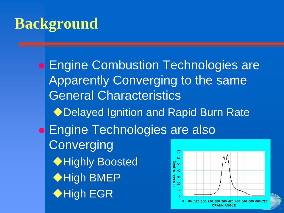
Engine Combustion Technologies are Apparently Converging to the same General Characteristics
Delayed Ignition and Rapid Burn RateEngine Technologies are also Converging
Highly BoostedHigh BMEPHigh EGR 0
10
20
30
40
50
60
70
0 60 120 180 240 300 360 420 480 540 600 660 720CRANK ANGLE
PRES
SUR
E (b
ar)
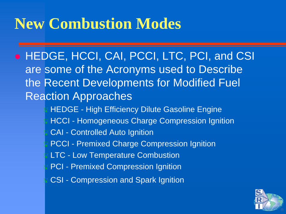
New Combustion Modes
HEDGE, HCCI, CAI, PCCI, LTC, PCI, and CSI are some of the Acronyms used to Describe the Recent Developments for Modified Fuel Reaction Approaches
HEDGE - High Efficiency Dilute Gasoline EngineHCCI - Homogeneous Charge Compression IgnitionCAI - Controlled Auto IgnitionPCCI - Premixed Charge Compression IgnitionLTC - Low Temperature CombustionPCI - Premixed Compression Ignition
CSI - Compression and Spark Ignition

HEDGE, HCCI, CAI, PCCI, LTC, PCI, and CSI
Common Factors include:Thick FlamesPart or all of the Fuel is PremixedAll Use EGRAll have Lower NOx All have Higher HC and CO
Differences Include:Degree of PremixingPM EmissionsOverall Equivalence RatioInitiation of ReactionPurpose/Application
Low EmissionsExhaust Gas Composition and Temperature Control

Best Combustion Phasing - Theoretical vs Practical
Thermodynamically Ideal Cycles Produce Highest Efficiency with Instantaneous Heat Release at TDCPractical Limitations Include
Noise due to Rapid Rates of Heat ReleaseIncreases in Friction due to Higher Bearing Loads and Small dV/dθ EffectsPeak Firing Pressure LimitsPressure Oscillations (maybe Knock)
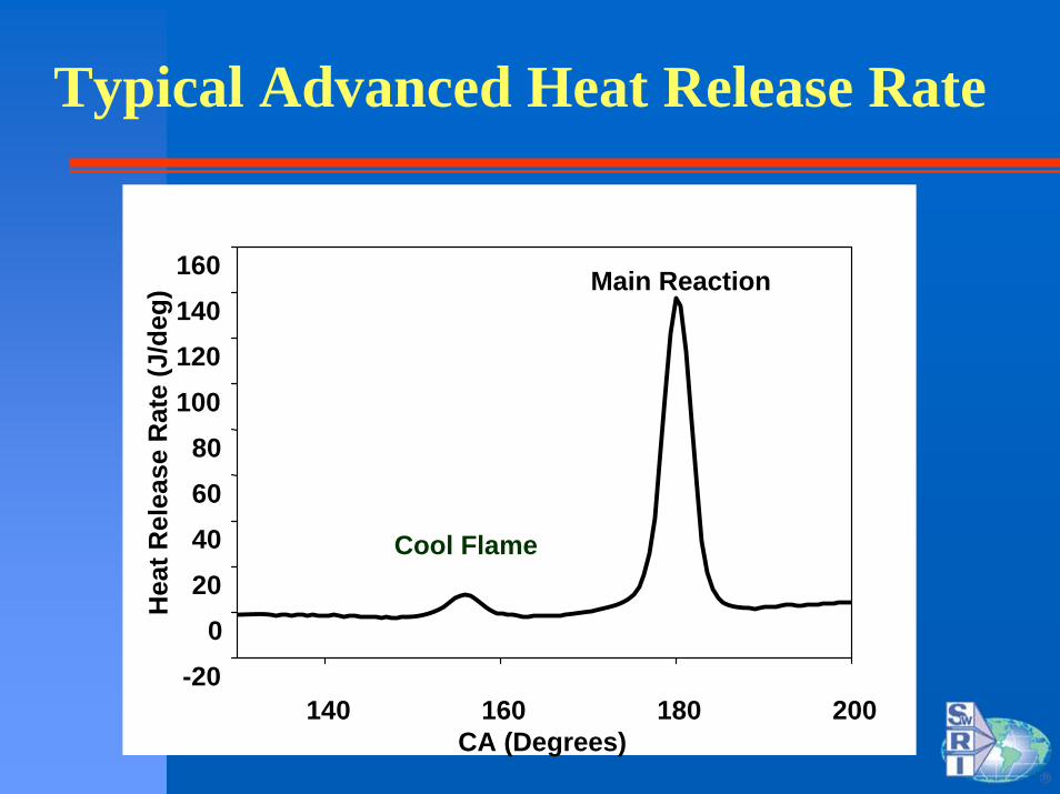
Typical Advanced Heat Release Rate
CA (Degrees)140 160 180 200
Hea
t Rel
ease
Rat
e (J
/deg
)
-200
20406080
100120140160 Main Reaction
Cool Flame
Approach
Use Cycle Simulation to Determine the Effects of Changing the Heat Release Rate Characteristics on the Emissions and the Efficiency
Mainly Concerned with NOx and BTE

HEDGE Performance PredictionsTools
Alamo Engine (A_E) Phenomenological, Zero Dimensional ModelsGas Exchange
Steady State Emptying & Filling (Checks With Steady State 1D Flow Code)
TCEnergy and Flow Balance for Selected Efficiencies, Wastegating (Vs Engine Speed)
CombustionWatson and Wiebe
FrictionChenn-flynn
AftertreatmentFixed Converter Efficiencies
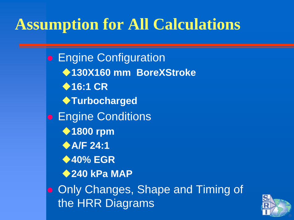
Assumption for All Calculations
Engine Configuration130X160 mm BoreXStroke16:1 CRTurbocharged
Engine Conditions1800 rpmA/F 24:140% EGR240 kPa MAP
Only Changes, Shape and Timing of the HRR Diagrams

Details on Shape and Timing Effect
Peak Efficiency Occurs in All Cases as 12o ATDCRapid to Slow Heat Release (Duration 10 to 30o) Results in 0.5% Change in BSFCCorresponding IMEP Drop of 0.5%
14.5
14.55
14.6
14.65
14.7
14.75
14.8
14.85
14.9
14.95
15
355 360 365 370 375 380 385
crank angle of main heat release peak [deg]
IME
P [b
ar]
200
202
204
206
208
210
212
214
216
218
220
BSF
C [
g/kW
-hr]
IMEP, narrow profileIMEP, middle profileIMEP, wide profileBSFC, narrow profileBSFC, middle profileBSFC, wide profile
0
0.05
0.1
0.15
0.2
0.25
340 345 350 355 360 365 370 375 380 385 390 395 400
crank angle [deg]
Future Diesel Engines
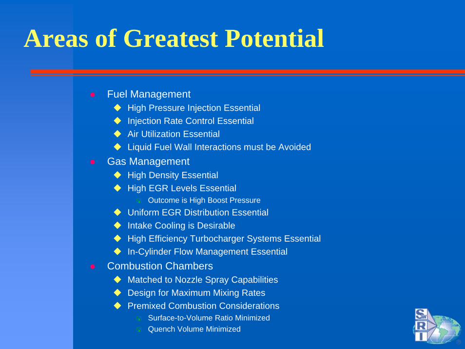
Areas of Greatest Potential
Fuel ManagementHigh Pressure Injection EssentialInjection Rate Control EssentialAir Utilization Essential Liquid Fuel Wall Interactions must be Avoided
Gas ManagementHigh Density EssentialHigh EGR Levels Essential
Outcome is High Boost PressureUniform EGR Distribution EssentialIntake Cooling is DesirableHigh Efficiency Turbocharger Systems EssentialIn-Cylinder Flow Management Essential
Combustion ChambersMatched to Nozzle Spray CapabilitiesDesign for Maximum Mixing RatesPremixed Combustion Considerations
Surface-to-Volume Ratio MinimizedQuench Volume Minimized
Premise
Lowest Possible Emissions and Highest Efficiency in Diesel Engines Achieved Using:
Ultra High Injection Pressure and Small HolesMassive EGRUltra High BoostWell Designed Pistons and Intake
High Injection Pressure and Small Holes

Fuel Injection - High PressureSwRI Results SAE 2002-01-0494
Single Hole Nozzles 0.086 to 0.18 mm DiaPeak Injection Pressures from 254 to 283 MPaHigher Mixing Rates and Smaller Drops
High Pressure ElectronicUnit Injector Operating on
a Fixed Cam at Constant Speeds

Fuel Injection - High Pressure
Mixing Parameter and Drop Size both Decrease with Smaller HolesPinj Increases with Smaller Holes
1. Mixing Rates Quantified in Termsof SwRI Defined Mixing Parameter
2. Mixing Parameter Defines the Mass of Fuel at Phi Greater Than 1.0 for than 0.6 ms
3. Rich Regions Mean More Soot

Fuel Injection - High Pressure
Small Holes Produce High Pressure, Small SMD, High Mixing Rates and Low Soot Formation Rates
0.144 mm
0.128 mm
0.086 mm

Fuel Injection - High Pressure
High Pressure does not Affect the Jet Penetration Rate in either Evaporating on Non-Evaporating Sprays
SwRI
Small Holes do Affect the Evaporation Rate and the Liquid Length in Evaporating Sprays
Fuel Injection - High Pressure
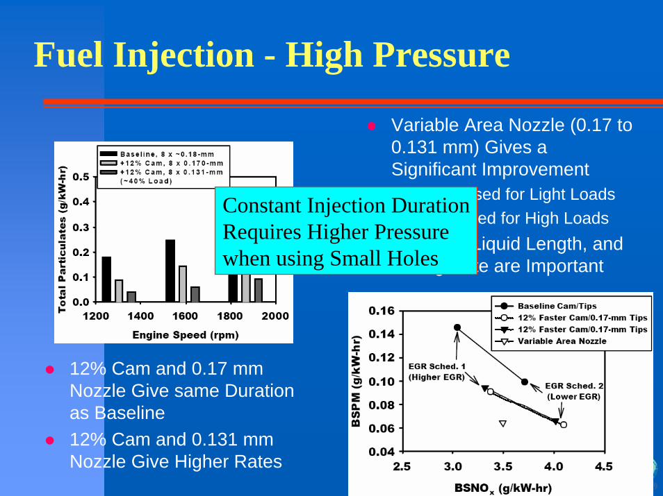
12% Cam and 0.17 mm Nozzle Give same Duration as Baseline12% Cam and 0.131 mm Nozzle Give Higher Rates
Variable Area Nozzle (0.17 to 0.131 mm) Gives a Significant Improvement
0131 Used for Light Loads0.17 Used for High Loads
Duration, Liquid Length, and Mixing Rate are Important
Constant Injection DurationRequires Higher Pressure when using Small Holes

High Boost
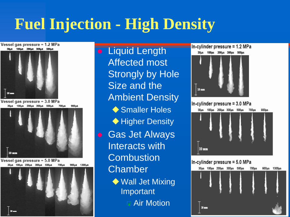
Fuel Injection - High DensityLiquid Length Affected most Strongly by Hole Size and the Ambient Density
Smaller HolesHigher Density
Gas Jet Always Interacts with Combustion Chamber
Wall Jet Mixing Important
Air Motion

Combustion Chamber Design

Fuel Injection - Jet-Wall Interaction
Combustion Chamber Design
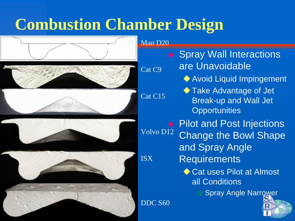
Spray Wall Interactions are Unavoidable
Avoid Liquid ImpingementTake Advantage of Jet Break-up and Wall Jet Opportunities
Pilot and Post Injections Change the Bowl Shape and Spray Angle Requirements
Cat uses Pilot at Almost all Conditions
Spray Angle Narrower
Man D20
Cat C9
Cat C15
Volvo D12
ISX
DDC S60
Fuel Injection WallFuel Injection Wall--Wetting IssuesWetting Issues
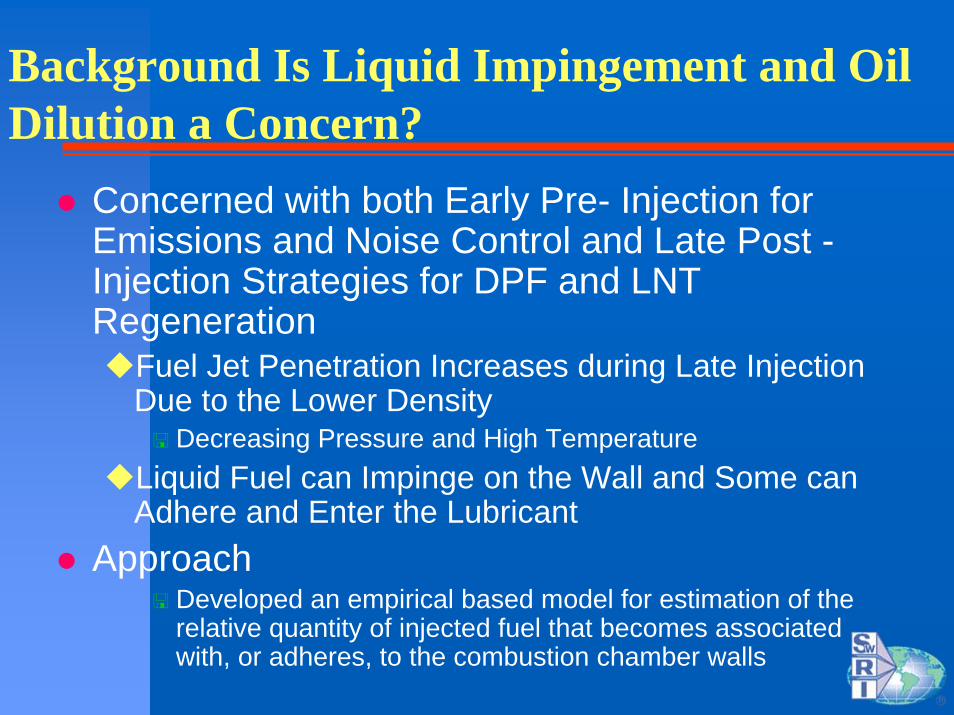
Background Is Liquid Impingement and Oil Dilution a Concern?
Concerned with both Early Pre- Injection for Emissions and Noise Control and Late Post -Injection Strategies for DPF and LNT Regeneration
Fuel Jet Penetration Increases during Late Injection Due to the Lower Density
Decreasing Pressure and High TemperatureLiquid Fuel can Impinge on the Wall and Some can Adhere and Enter the Lubricant
Approach Developed an empirical based model for estimation of the relative quantity of injected fuel that becomes associated with, or adheres, to the combustion chamber walls
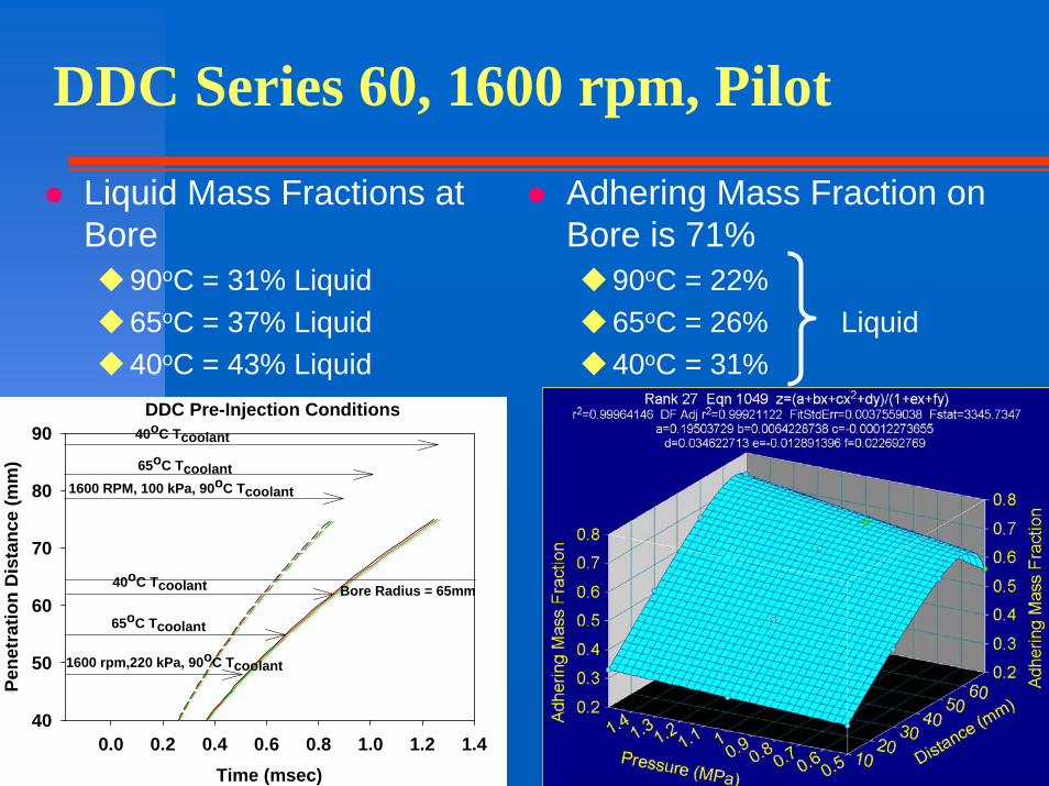
DDC Series 60, 1600 rpm, Pilot
Liquid Mass Fractions at Bore
90oC = 31% Liquid65oC = 37% Liquid40oC = 43% Liquid
Adhering Mass Fraction on Bore is 71%
90oC = 22%65oC = 26% Liquid 40oC = 31%
DDC Pre-Injection Conditions
Time (msec)0.0 0.2 0.4 0.6 0.8 1.0 1.2 1.4
Pene
trat
ion
Dis
tanc
e (m
m)
40
50
60
70
80
90
Bore Radius = 65mm
1600 rpm,220 kPa, 90oC Tcoolant
65oC Tcoolant
1600 RPM, 100 kPa, 90oC Tcoolant
65oC Tcoolant
40oC Tcoolant
40oC Tcoolant

OM 611, 1500 rpm, PilotLiquid Mass Fractions at Bore
High Load65oC = 22% Liquid40oC = 34% Liquid
Low Load90oC = 50% Liquid65oC = 64% Liquid40oC = 76% Liquid
Adhering Mass Fraction 71%High Load
65oC = 16% Liquid40oC = 24% Liquid
Low Load90oC = 36% Liquid65oC = 45% Liquid40oC = 54% Liquid
OM 611 Pre-Injection1500 rpm
Time (msec)
0.0 0.2 0.4 0.6 0.8 1.0 1.2 1.4
Pene
trat
ion
(mm
)
0
20
40
60
80
100
High Load, 65oC TcoolantHigh Load, 90oC Tcoolant
Low Load, 65oC Tcoolant
High Load, 40oC Tcoolant
Low Load, 90oC Tcoolant
Low Load, 40oC Tcoolant
Bore Radius = 44 mm
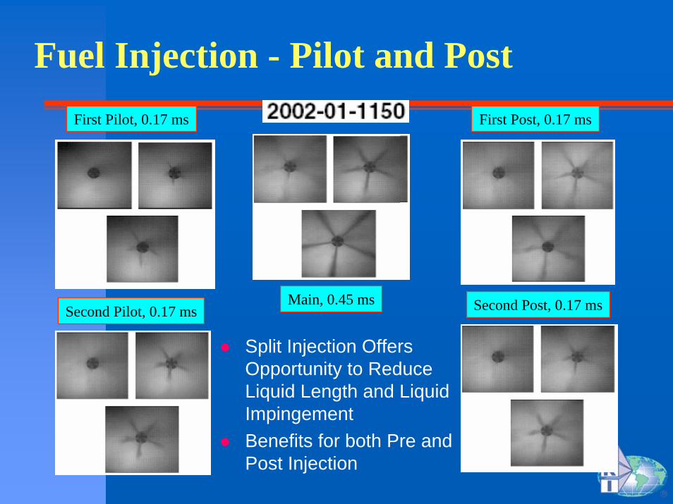
Fuel Injection - Pilot and Post
Split Injection Offers Opportunity to Reduce Liquid Length and Liquid ImpingementBenefits for both Pre and Post Injection
First Pilot, 0.17 ms
Second Pilot, 0.17 msMain, 0.45 ms
First Post, 0.17 ms
Second Post, 0.17 ms
Massive EGR

Massive EGR Background - EPA-Ford Data
EPA/Ford MIT Workshop 11/02
Massive EGR Background - Diffusion Burn Engine (Alternative to NOx After treatment)
SwRI Has Extensive Data Base of 8-Mode Data for Cat 3176 2.5 g/hp-hr NOx + HC EngineUse Cycle Simulation to Model Different Levels of EGRAssumed LP Loop EGR After DPFConditions Examined
Baseline - Good Prediction of Existing DataBaseline A/F and Timing + EGR + BoostBaseline Timing + A/F=25:1 + EGR + BoostA/F=15:1 + EGR + Boost + Timing Advance

Massive EGR
NOx
Test Name
Base Variable 25to1 15to1
NO
x (g
/hp-
hr)
0.00.20.40.60.81.01.21.41.61.82.0
BSFC
Test Name
Base Variable 25to1 15to1
BSF
C (g
/kw
-hr)
100
120
140
160
180
200
220
Baseline Engine Around 2 g/hp-hrBSFC Penalty with Variable Due to Back Pressure Increases25:1 A/F Produced Lots of Turbine Energy15:1 A/F Lowered the Air Flow and Boost Requirements
Massive EGR Issue
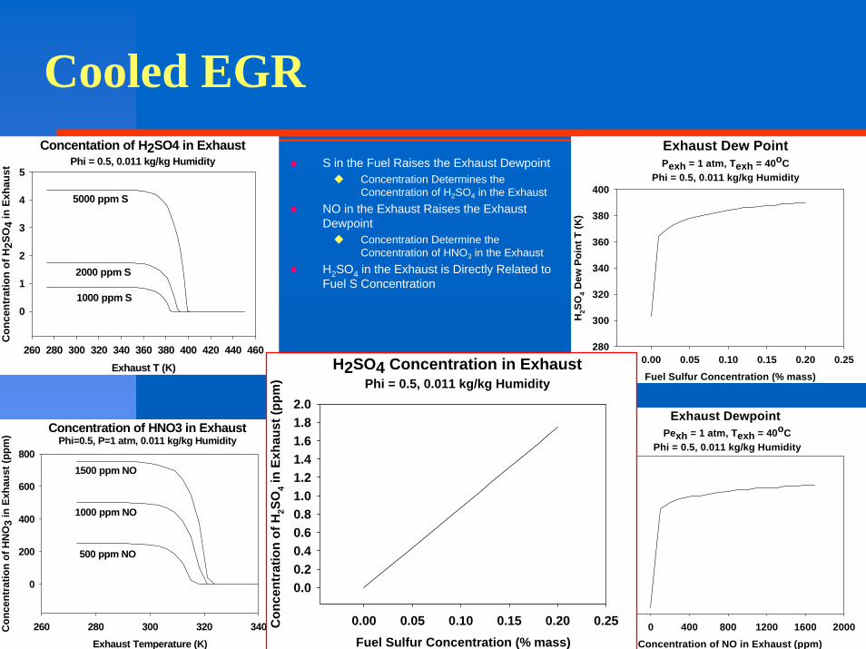
Cooled EGR
S in the Fuel Raises the Exhaust DewpointConcentration Determines the Concentration of H2SO4 in the Exhaust
NO in the Exhaust Raises the Exhaust Dewpoint
Concentration Determine the Concentration of HNO3 in the Exhaust
H2SO4 in the Exhaust is Directly Related to Fuel S Concentration
Concentation of H2SO4 in ExhaustPhi = 0.5, 0.011 kg/kg Humidity
Exhaust T (K)260 280 300 320 340 360 380 400 420 440 460
Con
cent
ratio
n of
H2S
O4
in E
xhau
st
0
1
2
3
4
5
1000 ppm S
2000 ppm S
5000 ppm S
Concentration of HNO3 in ExhaustPhi=0.5, P=1 atm, 0.011 kg/kg Humidity
Exhaust Temperature (K)260 280 300 320 340C
once
ntra
tion
of H
NO
3 in
Exh
aust
(ppm
)
0
200
400
600
800
500 ppm NO
1000 ppm NO
1500 ppm NO
Exhaust Dew PointPexh = 1 atm, Texh = 40oC
Phi = 0.5, 0.011 kg/kg Humidity
Fuel Sulfur Concentration (% mass)0.00 0.05 0.10 0.15 0.20 0.25
H2S
O4 D
ew P
oint
T (K
)
280
300
320
340
360
380
400
Exhaust Dewpoint Pexh = 1 atm, Texh = 40oC
Phi = 0.5, 0.011 kg/kg Humidity
Concentration of NO in Exhaust (ppm)0 400 800 1200 1600 2000
HN
O3
Dew
poin
t T (K
)
240
260
280
300
320
340
H2SO4 Concentration in ExhaustPhi = 0.5, 0.011 kg/kg Humidity
Fuel Sulfur Concentration (% mass)0.00 0.05 0.10 0.15 0.20 0.25C
once
ntra
tion
of H
2SO
4 in
Exha
ust (
ppm
)
0.00.20.40.60.81.01.21.41.61.82.0

Diffusion Burn Engine Fuel
Conventional Current Diesel Engine Fuel Appetite
Low Aromatics (high H/C Ratio)Lower Flame T and Lower NOxLower Propensity for Soot Formation
High Cetane NumberAdvanced Diesel Engine Fuel Appetite
Mixed Mode (Part Time HCCI and LTC)Low AromaticHigh Cetane Number (at least consistent)

So, Best Diffusion Burn System
Ultra High Injection Pressure and Small HolesMassive EGRUltra High BoostWell Designed Pistons and IntakeHigh Quality Diesel Fuel
Alternative Approaches
Full Time HCCINew Fuel Required
HEDGECould be the Lowest Cost Alternative
Thank You