Combustion Introduction Lecture
13
1 MAE 5310: COMBUSTION FUNDAMENTALS Introduction to Laminar Diffusion Flames: Non-Reacting Constant Density Laminar Jets Mechanical and Aerospace Engineering Department Florida Institute of Technology D. R. Kirk
-
Upload
jitesh-rane -
Category
Documents
-
view
30 -
download
5
description
intorduction to combustion.
Transcript of Combustion Introduction Lecture

1
MAE 5310: COMBUSTION FUNDAMENTALS
Introduction to Laminar Diffusion Flames:
Non-Reacting Constant Density Laminar Jets
Mechanical and Aerospace Engineering Department
Florida Institute of Technology
D. R. Kirk

2
LAMINAR DIFFUSION FLAME OVERVIEW
• Subject of lots of fundamental research
– Applications to residential burners (cooking ranges, ovens)
– Used to develop an understanding of how soot, NO2, CO are formed in diffusion burning
– Mathematically interesting: transcendental equation with Bessel functions (0th and 1st order)
• Introduce concept of conserved scalar (very useful in various aspects of combustion and introduced here)
• Desire to understand flame geometry (usually desire short flames)
– What parameters control flame size and shape
– What is the effect of different types of fuel
– Arrive at useful (simple) expression for flame lengths for circular-port and slot burners
CO2 production in diffusion flame

3
LAMINAR DIFFUSION FLAME OVERVIEW (LECTURE 1)• Reactants are initially separated, and reaction occurs only at the interface between fuel and
oxidizer (mixing and reaction taking place)
• Diffusion applies strictly to molecular diffusion of chemical species
• In turbulent diffusion flames, turbulent convection mixes fuel and air macroscopically, then molecular mixing completes the process so that chemical reactions can take place
Orange
Blue
Full range of throughoutreaction zone

4
NON-REACTING CONSTANT DENSITY LAMINAR JETS
• Examine non-reacting laminar jet of fluid (fuel) issuing into a infinite reservoir of quiescent fluid (oxidizer)
– Why? Simpler case to develop understanding of basic flow field
• Physical description of jet (Reference picture on next slide)
– Potential core: effects of viscous shear and diffusion have yet to be felt
• Both the velocity profile and nozzle-fluid mass fraction remain unchanged from their nozzle-exit values and are uniform in this region
• Similar to developing pipe flow, except that in a pipe conservation of mass requires uniform flow to accelerate
– Between potential core and jet ‘edge’, both velocity and fuel concentration (mass fraction) decrease monotonically to zero at edge of jet
• Beyond potential core (x > xc), effects of viscous shear and mass diffusion are active across whole width of jet
– Initial jet momentum is conserved through entire flow field
• Jet momentum flow at any x, J = momentum flow issuing from nozzle, Je

5
NON-REACTING CONSTANT DENSITY LAMINAR JETS
• Processes that control velocity field (convection and diffusion of momentum) are similar to processes that control fuel concentration field (convection and diffusion of mass)
• Distribution of YF(r,x) similar to distribution of ux(r,x)/ue
• Because of high concentration of fuel in center of jet, fuel molecules diffuse radically outward in accordance with Fick’s law (see assumptions page)
• Effect of moving downstream is to increase time available for diffusion to take place– Width of the region containing fuel molecules grows with axial distance, x, and centerline fuel
concentration decays
Centerlinevelocitydecay
Radialvelocitydecay
6
DETAILED ANALYSIS: NON-REACTING LAMINAR JETS
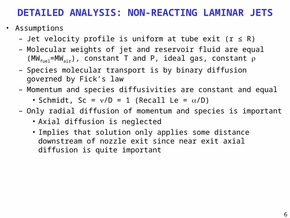
• Assumptions
– Jet velocity profile is uniform at tube exit (r ≤ R)
– Molecular weights of jet and reservoir fluid are equal (MWfuel=MWair), constant T and P, ideal gas, constant
– Species molecular transport is by binary diffusion governed by Fick’s law
– Momentum and species diffusivities are constant and equal
• Schmidt, Sc = /D = 1 (Recall Le = /D)
– Only radial diffusion of momentum and species is important
• Axial diffusion is neglected
• Implies that solution only applies some distance downstream of nozzle exit since near exit axial diffusion is quite important

7
GOVERNING EQUATIONS AND BOUNDARY CONDITIONS
00,
10,
00,
0,
0,
0,
0,0
0,0
0,0
1
01
,
RrY
YRrY
Rru
uRru
xY
xu
xr
Y
xr
u
xv
r
ur
rrr
uv
x
uu
r
ru
rx
u
F
eFF
x
ex
F
x
F
x
r
xxr
xx
rx
Boundary Layer Equations (see Schlichting or White)
Conservation of mass
Momentum
Boundary Conditions:
Along the jet centerline (r = 0)No sources of sinks of fluid along axisSymmetry
At large radii (r → ∞)
At jet exit (x =0) axial velocity and fuel massfraction are uniform
Everywhere else they are zero

8
FLOW FIELD RESULTS: SIMILARITY SOLUTION
The velocity field can be obtained by assuming the profiles to be similar. The idea of similarity is that the intrinsic shape of the profile is the same everywhere in the flow field
For this problem implication is that radial distribution ux(r,x), when normalized by local centerline velocity ux(0,r), is a function that depends only on similarity variable, r/x
Solution for axial velocity
Solution for radial velocity
contains similarity variable, r/x
Axial velocity in dimensionless form
Dimensionless centerline velocity
10,
221
21
22
3
21
22
375.0
41375.0
1
16
3
41
41
16
3
41
8
3
R
xRu
u
u
R
xRu
u
u
x
rJ
x
Jv
x
Ju
ee
e
x
ee
e
x
ee
e
er
ex

9
CENTERLINE VELOCITY DECAY FOR LAMINAR JETS
• Velocity decays inversely with axial distance and is directly proportional to jet Reynolds number, Re j
• Solution is not valid near nozzle• Decay is more rapid with lower Re jets
– As Re is decreased, relative importance of initial jet momentum becomes smaller in comparison with viscous shearing action, which slows the jet
• Figure also represents decay of centerline mass fraction, YF (see next slides)
Rej=2.97
Rej=29.7
Rej=297

10
SPREADING RATE, SPREADING ANGLE, JET HALF WIDTH
• Other parameters are frequently used to characterize jets
– Jet half-width, r1/2
• Radial location where jet velocity has decayed to 1/2 of centerline value
– Spreading rate
• Ratio of the jet half-width to the axial distance, x,
– Spreading angle, • Angle whose tangent is the spreading rate
• High Reynolds number jets are narrow
• Low Reynolds number jets are wide
• Consistent with Reynolds number dependence of velocity decay
x
r
Rux
r
jee
21
1
21
tan
Re
97.297.2

11
CONCENTRATION FIELD SOLUTION AND RESULTS
1
0,
221
2
22
Re375.0
41Re375.0
41
8
3
1
1
1
R
xY
R
xY
RuQ
Dx
QY
YY
r
Yr
rrD
r
Yv
x
Yu
r
ur
rrr
uv
x
uu
jF
jF
eF
FF
oxF
FFr
Fx
xxr
xx
Solution of concentration field is mathematically similar to governing equation for momentum conservation
If /D = 1 (Lewis number unity), function form of solution for YF is identical to what for ux/ue
QF is volumetric flow rate from nozzle
Written with Rej as controlling parameter
Centerline expression
Solutions can only be applied far from nozzle

12
EXAMPLES: NON-REACTING LAMINAR JETS• Part 1
– A jet of ethylene (C2H4) exits a 10 mm diameter nozzle into still air at 300 K, and 1 atm.– Compare spreading angles and axial location where jet centerline mass fraction drops to
stoichiometric value– Initial jet velocities of 10 cm/s and 1 cm/s, ethylene at 300 K is 1.023x10⁻⁹ N s/m2
– Answer comment:• Low-velocity jet is much wider• Fuel concentration of low-velocity jet decays to same value as high-velocity jet in 1/10 th
distance• Part 2
– Using 1 cm/s as a baseline case, determine what nozzle exit radius is required to maintain same flow rate if exit velocity is increased by a factor of 10 to 10 cm/s
• Part 3– Determine axial location for YF,0 = YF,stoichiometric for condition in Part 2 and compare with baseline– Answer comment:
• The distance calculated in Part 3 is identical to the 1 cm/s case in Part 1• Spatial fuel mass-fraction distribution depends on initial volumetric flow rate, Q, for a given
fuel ( = / = constant)
• Problem #4-40 from F. White, Viscous Fluid Flow:– Air at 20 °C and 1 atm issues from a circular hole and forms a round laminar jet. At 20 cm
downstream of the hole the maximum jet velocity is 35 cm/s. Estimate, at this position (a) the 1% jet thickness, (b) the jet mass flow, and (c) an appropriate Reynolds number for the jet

13
LOOK AGAIN AT BUNSEN BURNER
Fuel-rich pre-mixedinner flame
Secondary diffusion flameResults when CO and Hproducts from rich inner flameencounter ambient air
• What determines shape of flame? (velocity profile, flame speed, heat loss to tube wall)• Under what conditions will flame remain stationary? (flame speed must equal speed of normal
component of unburned gas at each location)• What factors influence laminar flame speed and flame thickness (, T, P, fuel type)• How to characterize blowoff and flashback• Most practical devices (Diesel-engine combustion) has premixed and diffusion burning