Combined electrochemical and microscopic study of porous ...
9
Combined electrochemical and microscopic study of porous enzymatic electrodes with direct electron transfer mechanism† M. Varni ˇ ci ´ c, a K. Bettenbrock, a D. Hermsdorf, a T. Vidakovi ´ c-Koch * a and K. Sundmacher ab In the present work electrochemical and microscopic methods have been utilized to get more insight into the complex relationship between the preparation route, structure and activity of porous enzymatic electrodes. Enzymatic electrodes have been prepared following two procedures. In one procedure enzymes were physically entrapped into a porous conductive matrix stabilized by “inert” binder (Vulcan- PVDF), while in the second one (Vulcan-Gelatin) gelatin has been used as a binder and the electrodes were cross-linked. Vulcan-PVDF electrodes show exceptionally high activity (up to 1.2 mA cm 2 ) compared to Vulcan-Gelatin electrodes (0.3 mA cm 2 ) at nominally lower enzyme loading. The scanning electron microscopy cross-sections of these electrodes revealed similar thicknesses, but a higher level of Vulcan nanomaterial agglomeration, somewhat reduced porosity and formation of gelatin film on top in the case of Vulcan-Gelatin electrodes. Additionally, fluorescence microscopy studies provided evidence of a higher level of enzyme agglomeration in the case of cross-linking. Although the gelatin matrix and the reduced catalyst layer porosity might slow down hydrogen peroxide diffusion, Vulcan-Gelatin electrodes are less affected by mass transfer conditions than Vulcan-PVDF electrodes. A plausible cause of the Vulcan-Gelatin electrode inferior performance is a lower number of active enzymes (lower enzyme utilization) compared to the Vulcan-PVDF electrode caused by a higher level of enzyme agglomeration in former case. 1. Introduction Broader applications of redox enzymes as catalysts in bio-based technical systems like enzymatic fuel cells, bio-batteries or bioelectrochemical reactors require signicant increase of the catalytic current per geometrical surface area of the electrode. This goal can be possibly achieved by improvement of the electrode structure, for example by introduction of high surface area materials, resulting in 3-D electrodes. 1–4 3-D structuring introduces various materials into electrode design; enzymes as catalytic elements, additives like hydrogels for enhancing the enzyme stability and various nanomaterials as conductive supports for immobilization of the biocatalyst. In addition, suitable mediators might be required if the enzyme does not allow direct electron transfer (DET). All these components are commonly self-organized in the catalyst layer and their disper- sion is unknown. A similar problem has been faced in the eld of conventional gas diffusion electrodes, where the designer task is to create a large so-called 3-phase interface. In case of enzymatic electrodes and DET, for optimal design, enzymes should be contacted by both an electron- and ion-conductive phases such that the reaction can take place. It can be easily anticipated that the formation of enzyme agglomerates, which might result from some preparation procedures, will drastically reduce the enzyme utilization. Similarly, additional compo- nents in the catalyst layer, like different hydrogels might break the electron conductive network, rendering parts of the catalyst layer inactive. It clearly follows that understanding of the rela- tionship between the preparation conditions and the electrode performance is crucial for the optimal design of enzymatic electrodes. Experimental methods for preparation of enzymatic elec- trodes can be roughly classied into two groups. First group of methods is based on physical immobilization of enzymes. The simplest approach is physical adsorption where only weak interactions between a support and an enzyme are involved. As supports, electron conductive materials like gold or carbon surfaces or in the case of 3-D electrodes, different types of nanomaterials have been typically used. 5–8 It has been demon- strated that using this method high performance enzymatic electrodes can be prepared even without any surface a Max Planck Institute for Dynamics of Complex Technical Systems, Sandtorstraße 1, 39106 Magdeburg, Germany. E-mail: [email protected] b Otto-von-Guericke University Magdeburg, Universit¨ atsplatz 2, 39106 Magdeburg, Germany † Electronic supplementary information (ESI) available. See DOI: 10.1039/c4ra07495e Cite this: RSC Adv. , 2014, 4, 36471 Received 21st May 2014 Accepted 1st August 2014 DOI: 10.1039/c4ra07495e www.rsc.org/advances This journal is © The Royal Society of Chemistry 2014 RSC Adv. , 2014, 4, 36471–36479 | 36471 RSC Advances PAPER Open Access Article. Published on 04 August 2014. Downloaded on 27/01/2015 13:59:09. This article is licensed under a Creative Commons Attribution-NonCommercial 3.0 Unported Licence. View Article Online View Journal | View Issue
Transcript of Combined electrochemical and microscopic study of porous ...

RSC Advances
PAPER
Ope
n A
cces
s A
rtic
le. P
ublis
hed
on 0
4 A
ugus
t 201
4. D
ownl
oade
d on
27/
01/2
015
13:5
9:09
. T
his
artic
le is
lice
nsed
und
er a
Cre
ativ
e C
omm
ons
Attr
ibut
ion-
Non
Com
mer
cial
3.0
Unp
orte
d L
icen
ce.
View Article OnlineView Journal | View Issue
Combined electr
aMax Planck Institute for Dynamics of Com
39106 Magdeburg, Germany. E-mail: vidakobOtto-von-Guericke University Magdeburg,
Germany
† Electronic supplementary informa10.1039/c4ra07495e
Cite this: RSC Adv., 2014, 4, 36471
Received 21st May 2014Accepted 1st August 2014
DOI: 10.1039/c4ra07495e
www.rsc.org/advances
This journal is © The Royal Society of C
ochemical and microscopic studyof porous enzymatic electrodes with directelectron transfer mechanism†
M. Varnicic,a K. Bettenbrock,a D. Hermsdorf,a T. Vidakovic-Koch*a
and K. Sundmacherab
In the present work electrochemical and microscopic methods have been utilized to get more insight into
the complex relationship between the preparation route, structure and activity of porous enzymatic
electrodes. Enzymatic electrodes have been prepared following two procedures. In one procedure
enzymes were physically entrapped into a porous conductive matrix stabilized by “inert” binder (Vulcan-
PVDF), while in the second one (Vulcan-Gelatin) gelatin has been used as a binder and the electrodes
were cross-linked. Vulcan-PVDF electrodes show exceptionally high activity (up to 1.2 mA cm�2)
compared to Vulcan-Gelatin electrodes (0.3 mA cm�2) at nominally lower enzyme loading. The scanning
electron microscopy cross-sections of these electrodes revealed similar thicknesses, but a higher level of
Vulcan nanomaterial agglomeration, somewhat reduced porosity and formation of gelatin film on top in
the case of Vulcan-Gelatin electrodes. Additionally, fluorescence microscopy studies provided evidence
of a higher level of enzyme agglomeration in the case of cross-linking. Although the gelatin matrix and
the reduced catalyst layer porosity might slow down hydrogen peroxide diffusion, Vulcan-Gelatin
electrodes are less affected by mass transfer conditions than Vulcan-PVDF electrodes. A plausible cause
of the Vulcan-Gelatin electrode inferior performance is a lower number of active enzymes (lower
enzyme utilization) compared to the Vulcan-PVDF electrode caused by a higher level of enzyme
agglomeration in former case.
1. Introduction
Broader applications of redox enzymes as catalysts in bio-basedtechnical systems like enzymatic fuel cells, bio-batteries orbioelectrochemical reactors require signicant increase of thecatalytic current per geometrical surface area of the electrode.This goal can be possibly achieved by improvement of theelectrode structure, for example by introduction of high surfacearea materials, resulting in 3-D electrodes.1–4 3-D structuringintroduces various materials into electrode design; enzymes ascatalytic elements, additives like hydrogels for enhancing theenzyme stability and various nanomaterials as conductivesupports for immobilization of the biocatalyst. In addition,suitable mediators might be required if the enzyme does notallow direct electron transfer (DET). All these components arecommonly self-organized in the catalyst layer and their disper-sion is unknown. A similar problem has been faced in the eld
plex Technical Systems, Sandtorstraße 1,
Universitatsplatz 2, 39106 Magdeburg,
tion (ESI) available. See DOI:
hemistry 2014
of conventional gas diffusion electrodes, where the designertask is to create a large so-called 3-phase interface. In case ofenzymatic electrodes and DET, for optimal design, enzymesshould be contacted by both an electron- and ion-conductivephases such that the reaction can take place. It can be easilyanticipated that the formation of enzyme agglomerates, whichmight result from some preparation procedures, will drasticallyreduce the enzyme utilization. Similarly, additional compo-nents in the catalyst layer, like different hydrogels might breakthe electron conductive network, rendering parts of the catalystlayer inactive. It clearly follows that understanding of the rela-tionship between the preparation conditions and the electrodeperformance is crucial for the optimal design of enzymaticelectrodes.
Experimental methods for preparation of enzymatic elec-trodes can be roughly classied into two groups. First group ofmethods is based on physical immobilization of enzymes. Thesimplest approach is physical adsorption where only weakinteractions between a support and an enzyme are involved. Assupports, electron conductive materials like gold or carbonsurfaces or in the case of 3-D electrodes, different types ofnanomaterials have been typically used.5–8 It has been demon-strated that using this method high performance enzymaticelectrodes can be prepared even without any surface
RSC Adv., 2014, 4, 36471–36479 | 36471

RSC Advances Paper
Ope
n A
cces
s A
rtic
le. P
ublis
hed
on 0
4 A
ugus
t 201
4. D
ownl
oade
d on
27/
01/2
015
13:5
9:09
. T
his
artic
le is
lice
nsed
und
er a
Cre
ativ
e C
omm
ons
Attr
ibut
ion-
Non
Com
mer
cial
3.0
Unp
orte
d L
icen
ce.
View Article Online
modication in order to promote DET.8 Another possibility forphysical immobilization is entrapment of enzymes into gelmatrixes such as gelatin, collagen and polysaccharides. Thisapproach usually stabilizes enzymes more than only physicaladsorption.9–11 Second group of methods is based on chemicalimmobilization of enzymes. These methods include covalentenzyme immobilization on the electrode surface which requiresfunctionalization of supports to create surface chemical groupsfor enzyme binding. Various surface modications have beendescribed in literature providing carboxyl, epoxy, acetyl oramino groups. These surface groups can be further eitherdirectly linked to enzymes or by using additional cross linkerslike glutaraldehyde.12
Although methods based on covalent attachment havemajor benet of higher enzyme stability at the expanse ofsomewhat lower activity due to reduction in enzyme exibility13
and in some cases oriented enzyme immobilization can beachieved proving especially benecial in case of the DET,14 weconcentrate in the present paper on physical methods forenzyme immobilization. The major goal is to check how thepreparation procedure inuences electrode structural param-eters like porosity and the electrode thickness. A furtherquestion is how enzyme organization at the conductive surfaceis dependent on the preparation procedure. To answer thesequestions porous enzymatic electrodes following two mainroutes of physical enzyme immobilization i.e. physicaladsorption into porous structure and enzyme entrapment intogelatin matrix stabilized by cross-linking have been prepared.As a model enzyme horseradish peroxidase showing DET hasbeen chosen. These electrodes have been characterized elec-trochemically for hydrogen peroxide reduction. Several factorswhich can inuence electrode activity like: electrode surfacearea, thickness, enzyme distribution and agglomeration havebeen hypothesized. To prove their inuence on observedactivity, the electrodes, in addition to electrochemicalmethods, have been characterized using different microscopicmethods. Scanning electron microscopy (SEM) has been usedin order to get information on overall electrode structure(porosity, and its thickness), while uorescence microscopyhas been employed to visualize enzyme distribution ondifferent supports.
2. Experimental part2.1 Reagents
Horseradish peroxidase (EC 1.11.1.7, HRP) from Amorica rusti-cana was supplied from Serva Electrophoresis GmbH. Hydrogenperoxide (H2O2, 30 wt%) and gelatin were purchased fromMerck. The H2O2 solution (3%) was prepared daily by dilution of30% hydrogen peroxide. Poly(vinylidene uoride) (PVDF),glutaraldehyde (GA) and 1-methyle-2-pyrrolidone were suppliedby Sigma Aldrich. For uorescence measurements DyLight 350NHS ester dye, supplied by Thermo scientic with an excitationwavelength of 353 nm and an emission wavelength of 432 nmwas used. All chemicals were of analytical reagent grade and allsolutions were prepared using ultrapure water from Millipore.
36472 | RSC Adv., 2014, 4, 36471–36479
2.2 Preparation of enzyme modied surfaces
For electrochemical measurements spectroscopically purecarbon (SPG) rods with impurities equal to or less than 2 ppmsupplied by Ted Pella, 330 INC, USA were cut in 11 mmdiameter discs and have been used as supports for enzymemodication. Before modication, they were polished by neemery paper (P1000), rinsed with deionized water and thenfurther polished with ordinary white paper to smoothen thesurface.15,16 For preparation of HRP modied electrodes, 50 mlof HRP solution in phosphate buffer (6 mg ml�1, pH 6.00) wasplaced on the top of the SPG disc and le for 2 h under ambientconditions. Aer that it was washed with distillated water andused for measurements. The discs have been mounted in asample holder for rotating disc electrode experiments (RDE,Radiometer Analytical, model ED101) with an opening of6 mm.
Cross-linked electrodes were prepared by dipping enzymemodied discs in GA solution (5% in water) for 1 min, rinsingwith water and drying at room temperature.17
Porous enzymatic electrodes incorporating enzymes andcarbon nanoparticles (Vulcan XC72R supplied by CabotCorporation) have been prepared by following two differentprocedures. In the rst procedure, denoted in text as “Vulcan-Gelatin”, gelatin has been used as a binder and electrodes werecross-linked. This procedure was similar to procedure reportedby Ivanov et al.18 Briey, 20 mg of carbon nanomaterial and10 mg HRP were suspended in 2% gelatin at 37 �C and cast onstainless steel discs degreased with acetone before usage.Electrodes were subsequently dried at ambient temperature andaerwards cross linked as previously described.
In the second procedure denoted in the text as “Vulcan-PVDF”, poly(vinylidene uoride) (PVDF) was used as a bindermaterial. This procedure was similar to those described byTsujimura et al.7 Shortly, carbon nanomaterial was dissolved in0.25 wt% PVDF solution in 1-methyle-2-pyrrolidone. In the nextstep, the ink was cast on SPG discs and le to dry at 60 �C. Aerdrying, electrodes were ready for modication with HRP solu-tion. Adsorption of enzyme on Vulcan electrodes was performedfor 2 h at room temperature by applying 50 ml of 6 mg ml�1 HRPsolution in 0.1 M phosphate buffer. Electrodes were then rinsedwith buffer and were ready for use.
For atomic force microscopy (AFM) experiments highlyoriented pyrolytic graphite (HOPG), supplied also from TedPella, 330 INC, USA was cut in the size of 5 mm � 4 mm. Forpreparation of HRP electrodes, a droplet of diluted HRP solu-tion in phosphate buffer (6 mgml�1, pH 6.00) was placed on thetop of the HOPG and le to dry. The dilution was made in orderto obtain a monolayer on the HOPG surface.
For uorescence microscopy experiments, both SPG andHOPG supports have been used. Before surface modication,HRP was labeled in the following way: HRP solution (2 mgml�1,pH 7.00) was mixed with uorescence dye dissolved in dime-thylformamide (DMF) and le for 1 h at room temperature.Aerwards, the excess non-reacted dye was removed by dialysisfor 4 h using three dialysis buffer changes. The labeled enzymeswere stored at 4 �C. For modication of SPG and HOPG
This journal is © The Royal Society of Chemistry 2014

Paper RSC Advances
Ope
n A
cces
s A
rtic
le. P
ublis
hed
on 0
4 A
ugus
t 201
4. D
ownl
oade
d on
27/
01/2
015
13:5
9:09
. T
his
artic
le is
lice
nsed
und
er a
Cre
ativ
e C
omm
ons
Attr
ibut
ion-
Non
Com
mer
cial
3.0
Unp
orte
d L
icen
ce.
View Article Online
surfaces, a droplet of diluted HRP solution was applied on anappropriate surface and le to dry.
Fig. 1 Cyclic voltammograms of porous enzymatic electrodes in
2.3 Measurements
Electrochemical experiments were performed using Autolabpotentiostat (PGSTAT302, Eco Chemie). Saturated calomel(SCE) and Pt electrodes were used as reference and counterelectrodes, respectively. The electrolyte was a 0.1 M phosphatebuffer with pH 6.0. All electrochemical experiments have beendone under nitrogen atmosphere at 400 rpm (rounds perminute). Steady state polarization curves were obtained byextracting the current values aer 60 s at constant potentialvalues.
Fluorescence microscopy has been performed with ImagerM1 Microscope, Carl Zeiss. The objective was EC Plan Neouarand lter set with excitation 365, beamer splitter 395 andemission 445/50 were used. In order to obtain high-contrastimages and at the same time to avoid saturation, differentexposure times have been used for different images (for furtherinformation please see the respective gure captions).
AFM measurements have been performed in air using 5500SPM (Agilent Technologies), with tapping mode (Acoustic ACMode). A rectangular silicon cantilever (PPP-NCSTAuD, Nano-sensors) with a nominal force constant of 7.4 N m�1 has beenused for the measurements.
Cross-sectional scanning electronmicroscopy (SEM) analysisof the enzymatic electrodes was performed using XL30 FEG (FEICompany).
phosphate buffer and in 1 mM hydrogen peroxide, without rotationand at 400 rpm. (a) Vulcan-PVDF and (b) Vulcan-Gelatin. Conditions:scan rate 5 mV s�1, pH 6.00, room temperature, N2 atmosphere,enzyme loadings (1 mg cm�2 for Vulcan-PVDF and 1.75 mg cm�2 forVulcan-Gelatin electrodes).
3. Results and discussion
Porous enzymatic electrodes prepared based on two immobili-zation strategies described in the Experimental section havebeen tested for their activities towards hydrogen peroxidereduction (Fig. 1). Shortly, in one procedure, enzymes areimmobilized by physical entrapment into a porous structurestabilized by “inert” binder (Vulcan-PVDF) while in the otherone “active” binder (gelatin) and cross-linking to form andstabilize enzyme/nanoparticle composites (Vulcan-Gelatin) hasbeen used. The performances of the enzymatic electrodes havebeen evaluated by means of cyclic voltammetry and steady statemeasurements. Fig. 1 shows cyclic voltammograms of theVulcan-PVDF (Fig. 1a) and Vulcan-Gelatin (Fig. 1b) electrodes inphosphate buffer in absence and in presence of hydrogenperoxide, in quiet solution (0 rpm) and at 400 rpm rotation. Ascan be seen aer addition of hydrogen peroxide, an increase ofthe reduction current can be observed indicating biocatalyticreduction of H2O2 by HRP. According to expectations16 theelectrode activity in quiet solution is lower than at 400 rpm. Thisis especially true for Vulcan-PVDF electrode (current density(aer background current subtraction) in the limiting currentregion is ca. 0.66 mA cm�2 with and 0.13 mA cm�2 withoutstirring), while Vulcan-Gelatin electrode is less affected by stir-ring conditions (current density in the limiting current region isca. 0.22 mA cm�2 with and 0.13 mA cm�2 without stirring).These results indicate stronger mass transfer limitations in the
This journal is © The Royal Society of Chemistry 2014
Vulcan-PVDF compared to Vulcan-Gelatin case. Furthermore,these results suggest higher amount of active enzymes in theVulcan-PVDF case.
The activity of Vulcan-Gelatin electrode in terms of currentdensities is similar to reported values in literature, whileVulcan-PVDF electrode outperforms all literature results. Someexamples are composite electrodes made of HRP immobilizedon carbon nanotubes19 with activity of ca. 0.1 mA cm�2 at 1 mMhydrogen peroxide concentration in the limiting current region,or HRP immobilized on single walls carbon nanotubes(SWCNT) with activity of ca. 0.03 mA cm�2 at 0.3 mM hydrogenperoxide concentration.20 It should be stressed out that for faircomparison of electrode activities in different publications,some benchmarking is necessary. This benchmarking includesin addition to substrate concentration, pH and temperature,control of mass transfer resistance in the Nernstian diffusionlayer and the same method for sampling of current–potentialdata. The control of mass transfer resistance in the diffusionlayer over time can be only achieved under forced convectionconditions. This control is very important for quantitativedescription of electrode processes since in quiet solution the
RSC Adv., 2014, 4, 36471–36479 | 36473

RSC Advances Paper
Ope
n A
cces
s A
rtic
le. P
ublis
hed
on 0
4 A
ugus
t 201
4. D
ownl
oade
d on
27/
01/2
015
13:5
9:09
. T
his
artic
le is
lice
nsed
und
er a
Cre
ativ
e C
omm
ons
Attr
ibut
ion-
Non
Com
mer
cial
3.0
Unp
orte
d L
icen
ce.
View Article Online
thickness of the diffusion layer is changing over time of theexperiment in a quantitatively unpredictable manner. Thisappears especially important in processes strongly controlled bymass transfer. For example in the present case the activity ofVulcan-PVDF electrode is highly underestimated under non-stirred conditions in comparison to Vulcan-Gelatin electrode.
The inuence of the sampling method has been demon-strated in Fig. 2 below. The comparison between backgroundsubtracted cyclic voltammogram at 5 mV s�1 with steady statemeasurements at two different sampling times (60 and 120 s),show that the cyclic voltammetry overestimates signicantly thecatalytic current. Regarding the sampling time, one can see thatthe results aer 60 s and 120 s are almost identical for whichreason 60 s sampling time has been chosen in furthermeasurements. The chronoaperometric data which have beenused for construction of steady state current density–potentialrelationship are presented in Fig. S1 (ESI†).
Having in mind previous discussion, forced convectionconditions at constant rotation rate of 400 rpm and steady statemethod with sampling time of 60 s have been xed in furthermeasurements.
As can be seen in Fig. 2 both electrodes show high onsetpotential values (ca. 0.62 and 0.57 V vs. SCE for Vulcan-PVDF
Fig. 2 Comparison of the electrode performance obtained usingcyclic voltammetry and steady state methods. (a) Vulcan-PVDF and (b)Vulcan-Gelatin electrodes. Conditions: scan rate 5 mV s�1 pH 6.00, N2
atmosphere, enzyme loadings: Vulcan-PVDF – 1 mg cm�2 andVulcan-Gelatin – 1.75 mg cm�2.
36474 | RSC Adv., 2014, 4, 36471–36479
and Vulcan-Gelatin electrodes respectively), comparable withliterature values on high surface area electrodes e.g. 0.57 V vs.SCE at pH 6,20 0.55 V vs. SCE at pH 7,19 and 0.63 V vs. SCE at pH7.00.21 The onset potential value of the Vulcan-PVDF electrode,is ca. 50 mV more positive than the measured value for Vulcan-Gelatin electrode. In general, for the same type of peroxidase,onset potential values depend on pH of the solution,22 onperoxide concentration, (with more negative onset potentialvalues at lower concentrations) and on immobilization proce-dure. The later effect might impact enzyme orientation at thesurface as well as the number of active enzymes. It can beanticipated that both issues might contribute to observeddifferences between onset potentials of Vulcan-PVDF andVulcan-Gelatin electrodes. In the case of Vulcan-PVDF elec-trodes enzymes were only physically adsorbed, while in the caseof Vulcan-Gelatin procedure they were also cross-linked. Onecan hypothesize that enzyme cross-linking causes less favoredenzyme orientations than the physical adsorption of enzymes(Vulcan-PVDF case) resulting in more negative onset potential.As it was discussed the results in Fig. 1 and 2 indicate highernumber of active enzymes in the case of Vulcan-PVDF electrode.Alternatively at the same number of active enzymes, lowering ofthe kinetic constants of cross-linked enzymes could also explainthe experimental observations. These two effects can not beseparated, without being able to quantify the number of activeenzymes (ref. 16 and references therein).
Next, the inuence of enzyme loading at constant peroxideconcentration has been checked for both immobilizationprocedures (Fig. 3). As can be seen in Fig. 2 Vulcan-PVDF elec-trodes are more active than Vulcan-Gelatin electrodes in thewhole range of studied loadings. The dependences of currentdensities at constant potential (0.0 V vs. SCE) on enzyme loadingshow a bell-shaped form with optimal loading at ca. 1 mg cm�2
and 1.75 mg cm�2 for Vulcan-PVDF and Vulcan-Gelatin elec-trodes respectively. While an initial increase of the activity withenzyme loading can be correlated with an increase of thenumber of active enzymes, decrease of activity at higher enzymeloadings might be a consequence of a mass transfer resistanceincrease, in the catalyst layer at higher enzyme loadings.
Fig. 3 Influence of enzyme loading on the activity of Vulcan HRP –electrodes. Conditions: 1 mM hydrogen peroxide, electrode potential0.0 V vs. SCE, 400 rpm, N2 atmosphere, pH 6.00.
This journal is © The Royal Society of Chemistry 2014

Paper RSC Advances
Ope
n A
cces
s A
rtic
le. P
ublis
hed
on 0
4 A
ugus
t 201
4. D
ownl
oade
d on
27/
01/2
015
13:5
9:09
. T
his
artic
le is
lice
nsed
und
er a
Cre
ativ
e C
omm
ons
Attr
ibut
ion-
Non
Com
mer
cial
3.0
Unp
orte
d L
icen
ce.
View Article Online
As a consequence dead portions of the catalyst layer can becreated, which are under supplied with substrate.23 In additionto this reason unfavoured enzyme orientation is oen com-mented in literature as a possible cause of activity decrease athigher loadings.21 Regarding different optimal loadings for twodifferent procedures there are several reasons which cancontribute to this observation. In accordance to our recentmodeling study23 utilization of the catalyst layer depends on thethickness of the layer, its porosity, number of active enzymesand the concentration of reactant. In addition at higherhydrogen peroxide concentrations the effect of enzyme inhibi-tion can become evident.24 The results indicate a lower numberof active enzymes in Vulcan-Gelatin case. The reduced numberof active enzymes, at the same concentration of reactant cancause better utilization of the catalyst layer in case of Vulcan-Gelatin electrode shiing position of the maximum to higherenzyme loadings.
The effect of hydrogen peroxide concentration was furtherstudied for two optimal loadings of Vulcan-PVDF and Vulcan-Gelatin electrodes (Fig. 4). The increase of reduction currentwith an increase of hydrogen peroxide concentration indicatesthat the immobilized HRP retains its catalytic activity for thereduction of hydrogen peroxide. The results show that satura-tion conditions are reached at ca. 5 mM and ca. 4 mM hydrogenperoxide concentration for Vulcan-PVDF and Vulcan-Gelatinelectrodes respectively. The Vulcan-PVDF electrode has excel-lent performance comparable with performance of bilirubinoxidase (BOD) based biocathode prepared on Ketjen Black (KB)suggesting that also these HRP-enzymatic electrodes are suit-able for biofuel cell application.25
To understand the origin of the high activity of Vulcan-PVDFand lower activity of Vulcan-Gelatin electrodes, these two elec-trodes have been further characterized electrochemically in theabsence of hydrogen peroxide as well as physically with SEM.The electrochemical characterization in the absence of activecomponent (hydrogen peroxide) gives a rough orientation onactive surface area available for enzyme adsorption. As can be
Fig. 4 Influence of the hydrogen peroxide concentration on theactivity of Vulcan HRP – electrodes at optimized enzyme loadings.Conditions: enzyme loadings 1.75 mg cm�2 for Vulcan-Gelatin and 1.1mg cm�2 for Vulcan-PVDF, electrode potential 0.0 V vs. SCE, 400 rpm,N2 atmosphere, pH 6.00.
This journal is © The Royal Society of Chemistry 2014
seen in Fig. 5, the CVs of both electrodes in absence of hydrogenperoxide appear almost identical, showing only characteristicfeatures of carbon material.26 Although Vulcan-Gelatin elec-trode had a bit higher Vulcan loading (3.6 mg cm�2) thanVulcan-PVDF electrode (3.0 mg cm�2), the results indicatesimilar active surface area for enzyme adsorption.
Furthermore cross-sections of two types of electrodes havebeen studied by SEM (Fig. 6). It can be seen that the thicknessesof two electrodes are 47 mm and 53 mm for Vulcan-Gelatin andVulcan-PVDF electrodes respectively. Magnication of theelectrode cross sections (Fig. 6c and d) provides better insightsinto electrode morphology. Vulcan nanomaterial in Vulcan-Gelatin electrode forms knot-shaped agglomerates with the sizearound 250 nm which are signicantly bigger than unit-struc-tures in the Vulcan-PVDF electrode. This can be due to hydro-philic nature of gelatin, resulting in a higher degree ofagglomeration of hydrophobic Vulcan nanoparticles. If PVDFwas used, distribution of Vulcan nanoparticles is more uniformand ca. 100 nm spherical units can be observed (Fig. 6d). Thisindicate lessening of available surface area in the case ofVulcan-Gelatin electrode compared to Vulcan-PVDF electrode,which is also in accordance to electrochemical characterization(Fig. 5) where the CVs of both electrodes appear very similardespite a bit higher Vulcan loading of Vulcan-Gelatin electrode.
The top views of the Vulcan-Gelatin and Vulcan-PVDF elec-trode surfaces are also affected by preparation conditions asshown in Fig. 6e and f. Vulcan-Gelatin electrode has a layer ofgelatin on the top which additionally stabilizes the electrodestructure, might prevent/decrease leaching of enzymes, butintroduces additional mass transfer resistance for hydrogenperoxide transfer in the catalyst layer. The surface of Vulcan-PVDF electrode has similar morphology to the electrode crosssection. Additionally, porosities of both electrodes have beenestimated based on the electrode thickness measured by SEMand theoretical compact electrode thickness based on loadingsof all electrode components and their densities, according tothe equation provided by Gode et al.27 Taking into accountdensity of dry gelatin, the estimated value of electrode porosityfor Vulcan-Gelatin procedure is 0.27. Calculated porosity for the
Fig. 5 Cyclic voltammograms of Vulcan HRP – electrodes in 0.1 Mphosphate buffer. Conditions: scan rate 20 mV s�1, 400 rpm, N2
atmosphere, pH 6.00.
RSC Adv., 2014, 4, 36471–36479 | 36475
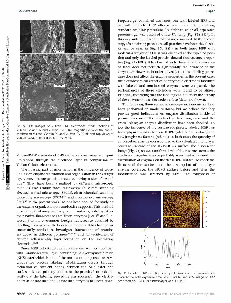
Fig. 6 SEM images of Vulcan HRP electrodes: cross sections ofVulcan-Gelatin (a) and Vulcan-PVDF (b); magnified view of the cross-sections of Vulcan-Gelatin (c) and Vulcan-PVDF (d) and top views ofVulcan-Gelatin (e) and Vulcan-PVDF (f).
Fig. 7 Labeled-HRP on HOPG support visualized by fluorescencemicroscopy with exposure time of 200 ms (a) and AFM image of HRPadsorbed on HOPG in a monolayer at pH 6 (b).
RSC Advances Paper
Ope
n A
cces
s A
rtic
le. P
ublis
hed
on 0
4 A
ugus
t 201
4. D
ownl
oade
d on
27/
01/2
015
13:5
9:09
. T
his
artic
le is
lice
nsed
und
er a
Cre
ativ
e C
omm
ons
Attr
ibut
ion-
Non
Com
mer
cial
3.0
Unp
orte
d L
icen
ce.
View Article Online
Vulcan-PVDF electrode of 0.45 indicates lower mass transportlimitations through the electrode layer in comparison toVulcan-Gelatin electrodes.
The missing part of information is the inuence of cross-linking on enzyme distribution and organization in the catalystlayer. Enzymes are protein structures having a size of severalnm.28 They have been visualized by different microscopicmethods like atomic force microscopy (AFM)29–33 scanningelectrochemical microscopy (SECM), electrochemical scanningtunnelling microscopy (ESTM)34 and uorescence microscopy(FM).35 In the present work FM has been applied for studyingthe enzyme organization on conductive supports. This methodprovides optical images of enzymes on surfaces, utilizing eithertheir native uorescence (e.g. avin enzymes (FAD)36 are uo-rescent) or more common foreign uorescence obtained bylabelling of enzymes with uorescent markers. It has been so farsuccessfully applied to investigate interactions of proteinsentrapped in different polymers35,37–39 and for verication ofenzyme self-assembly layer formation on the microarrayelectrodes.40,41
Since, HRP lacks its natural uorescence it was rst modiedwith amine-reactive dye containing N-hydroxysuccinimide(NHS) ester which is one of the most commonly used reactivegroups for protein labeling. Modication occurs throughformation of covalent bonds between the NHS ester andsurface-oriented primary amines of the protein.42 In order toverify that the labeling procedure was successful, the electro-phoresis of modied and unmodied enzymes has been done.
36476 | RSC Adv., 2014, 4, 36471–36479
Prepared gel contained two lanes, one with labeled HRP andone with unlabeled HRP. Aer separation and before applyingstandard staining procedure (in order to color all separatedproteins), gel was observed under UV lamp (Fig. S2a ESI†). Inthis way, only uorescent proteins are visualized. In the secondstep, aer staining procedure, all proteins have been visualized.As can be seen in Fig. S2b ESI,† in both lanes HRP withmolecular weight of 44 kDa was observed at the expected posi-tion and only the labeled protein showed uorescence proper-ties (Fig. S2a ESI†). It has been already shown that the presenceof label does not perturb signicantly the behavior of theenzymes.35 However, in order to verify that the labeling proce-dure does not affect the enzyme properties in the present case,the electrochemical activities of enzymatic electrodes modiedwith labeled and non-labeled enzymes were compared. Theperformances of these electrodes were found to be almostidentical, indicating that the labeling did not affect the activityof the enzyme on the electrode surface (data not shown).
The following uorescence microscopy measurements havebeen performed on model surfaces, but we believe that theyprovide good indications on enzyme distribution inside ofporous structures. The effects of surface roughness and thecross-linking on enzyme distribution have been checked. Totest the inuence of the surface roughness, labeled HRP hasbeen physically adsorbed on HOPG (ideally at surface) andSPG (roughness factor 5 (ref. 43)). In both cases the quantity ofan adsorbed enzyme corresponded to the calculated monolayercoverage. In case of the HRP–HOPG surface, the uorescentimage (Fig. 7a) shows a uniform level of uorescence across thewhole surface, which can be probably associated with a uniformdistribution of enzymes on the at HOPG surface. To check theatness of the surface and the assumption of monolayerenzyme coverage, the HOPG surface before and aer themodication was screened by AFM. The roughness of
This journal is © The Royal Society of Chemistry 2014

Fig. 9 Fluorescence microscopy images of labeled-HRP after CLusing 5% glutaraldehyde on HOPG, imaged with the exposure time of100 ms (a) and on spectroscopic graphite surface with 200 msexposure time (b).
Paper RSC Advances
Ope
n A
cces
s A
rtic
le. P
ublis
hed
on 0
4 A
ugus
t 201
4. D
ownl
oade
d on
27/
01/2
015
13:5
9:09
. T
his
artic
le is
lice
nsed
und
er a
Cre
ativ
e C
omm
ons
Attr
ibut
ion-
Non
Com
mer
cial
3.0
Unp
orte
d L
icen
ce.
View Article Online
unmodied HOPG was found to be low with a maximum heightof the prole below 0.4 nm (Fig. S3 ESI†). The AFM images withphysically distributed enzyme patterns at relatively large areas(Fig. 7b). This pattern formation was strongly pH sensitive,showing for example more expressed branchy-like structures atpH 7.2 (Fig. S4 ESI†). The average heights of these structures areca. 4 nm and ca. 5 nm at pH 6 and pH 7.2, respectively. Thesevalues correspond well to reported values of HRP dimensions(6.2 � 4.3 � 1.2 nm (ref. 3 and 34)) indicating monolayerformation. Interestingly, although the height of enzyme aggre-gates is not pH dependent, the width of these aggregates is pHsensitive (ca. 100 nm and ca. 300 nm at pH 6 and pH 7.2,respectively; Fig. 7b and S4 ESI†). This can possibly have animpact on the resulting enzyme catalytic activity.
Unlike the HRP–HOPG surface, the uorescence image ofHRP–graphite surface (Fig. 8a) shows a non-uniform distribu-tion of uorescence with blue spots of different intensities aswell as very dark areas. These dark areas have a very low level ofuorescence (ca. 200 A.U.) and can be probably ascribed toenzyme-free parts of the surface. The blue spots with differentintensities indicate a non-uniform distribution of enzymes onthe remaining part of the surface, with spots showing a higherlevel of uorescence (ca. 1500 A.U.) probably indicating enzymeagglomeration, while spots with a lower level of uorescence(ca. 800 A.U.) (similar to those observed on HOPG surface)indicating monolayer enzyme adsorption.
The non-uniform distribution of enzymes on the graphitesurface corresponds well to the higher level of its surfaceinhomogeneity compared to HOPG. This result suggests that amonolayer of enzymes can be formed only on ideally atsurfaces like HOPG. If the roughness of the surface is of higherorder than the size of the enzyme one can always expect theformation of agglomerates and consequently a non-uniformenzyme distribution. It can be further anticipated that theadsorption strength between the enzyme and the surface willvary for different adsorption sites like at areas or depressionson the surface. This is conrmed by the image in Fig. 8b wherethe graphite surface aer pronounced electrode rotation isshown. One can easily see that the blue spots of lower intensity,which were assigned to monolayer adsorption, disappeared.The enzyme distribution on the surface has a signicant inu-ence on the enzyme activity, especially in the case of DET, where
Fig. 8 Fluorescence microscopy images of labeled-HRP on the SPGbefore rotation, 200ms exposure time (a) and after 2 h rotation in RDE,400 rpm, 100 ms exposure time (b).
This journal is © The Royal Society of Chemistry 2014
the enzyme's active centers should be in close proximity of theelectrode to allow for electron transfer. Our results indicate thatin addition to orientation, enzyme agglomeration decreases thenumber of enzymes being in direct contact with the electrodesurface.
The effect of cross-linking has been studied on HOPG andgraphite surfaces (Fig. 9). According to literature cross-linkingincreases enzyme stability without inuencing its activity(except in case of extremely high ratios between cross-linker andenzymes).44
In addition, cross-linking is responsible for formation ofenzyme agglomerates which can be clearly seen on both HOPGand spectroscopic graphite surfaces (Fig. 9a and b). While onHOPG one large agglomerate forms, on spectroscopic graphite“agglomeration centers” which differ in shape and size can beobserved. The average level of uorescence for these crosslinked agglomerates on spectroscopic graphite is ca. 3200� 300A.U. (prole shown only for one agglomerate), while the level ofuorescence for agglomerates on graphite without CL hasvalues of ca. 1500 A.U. It can be anticipated that formation ofenzyme-agglomerates decreases the number of active enzymes
Fig. 10 Steady state polarization curves of hydrogen peroxidereduction on the HRP-modified graphite electrodes without and withcross linking. Conditions: 160 mM hydrogen peroxide concentration,400 rpm, N2 atmosphere, pH 6.00.
RSC Adv., 2014, 4, 36471–36479 | 36477

RSC Advances Paper
Ope
n A
cces
s A
rtic
le. P
ublis
hed
on 0
4 A
ugus
t 201
4. D
ownl
oade
d on
27/
01/2
015
13:5
9:09
. T
his
artic
le is
lice
nsed
und
er a
Cre
ativ
e C
omm
ons
Attr
ibut
ion-
Non
Com
mer
cial
3.0
Unp
orte
d L
icen
ce.
View Article Online
in contact with the electrode surface, which reduces further bio-electrode activity. This has been conrmed in experiment wherethe activities of non and cross-linked electrodes have beencompared (Fig. 10). On the other hand CL increases the stabilityof the electrode, probably by decreasing the level of leaching.The calculated loss of activity aer 2 hours at constant potentialof 0.0 V vs. SCE was ca. 13% for CL electrode and ca. 28% for thenon-cross-linked electrode (data not shown).
4. Conclusions
In this study porous enzymatic electrodes have been preparedby following immobilization protocols with and without cross-linking. It was demonstrated that the electrodes withouthydrogels and further stabilization through cross-linking showsignicantly higher activities for the same nominal enzymeloading. Optimized HRP-enzymatic electrodes exhibit highactivity towards hydrogen peroxide reduction reaching currentdensity of ca. 1.2 mA cm�2, which according to our knowledgehas not been reported in literature so far.
The electrochemical characterization in the absence ofreactant hydrogen peroxide has shown that both electrodeshave almost the same electrochemically active surface area.SEM cross sections demonstrate that the thicknesses of twoelectrodes were similar, but porosity of Vulcan-Gelatin electrodewas reduced in comparison to Vulcan-PVDF electrode. It wasshown that addition of gelatin leads to stronger agglomerationof Vulcan nanomaterial. In addition gelatin forms a lm on top,which can cause mass transfer limitations. The uorescencemicroscopy studies on model surfaces have demonstrated thatlevel of enzyme agglomeration depends on surface roughnessand it increases upon cross-linking. This has a negative effecton electrode activity in both onset potential values and overallactivity. Physical adsorption leads to uniform enzyme distri-bution only in the case of ideally at surfaces. On macroscopi-cally at surfaces, enzyme agglomerates are also formed but inless extent compared to cross-linked conditions. The surfaceutilization for enzyme adsorption is very small.
Although the presence of gelatin matrix and the reducedporosity in Vulcan-Gelatin electrodes might slow down signi-cantly mass transfer of the substrate through these electrodes,Vulcan-Gelatin electrodes are less affected by mass transferconditions than Vulcan-PVDF electrodes. This implies higherreaction resistance in the case of Vulcan-Gelatin. According toour results, higher reaction resistance is caused by smallernumber of active enzymes or by lowering of the kineticconstants of cross-linked enzymes. These two effects can not beseparated, without being able to quantify the number of activeenzymes.
Acknowledgements
The authors gratefully acknowledge the support of Helga Tiet-gens and Markus Ikert, during uorescence microscopy anal-ysis and AFM measurements and group of Dr Erdmann Rapp,for support with electrophoresis.
36478 | RSC Adv., 2014, 4, 36471–36479
Notes and references
1 I. Ivanov, T. Vidakovic-Koch and K. Sundmacher, Energies,2010, 3, 803–846.
2 T. Tamaki, Top. Catal., 2012, 55, 1162–1180.3 M. H. Osman, A. A. Shah and F. C. Walsh, Biosens.Bioelectron., 2011, 26, 3087–3102.
4 J. A. Cracknell, K. A. Vincent and F. A. Armstrong, Chem. Rev.,2008, 108, 2439–2461.
5 X. J. Wang, M. Falk, R. Ortiz, H. Matsumura, J. Bobacka,R. Ludwig, M. Bergelin, L. Gorton and S. Shleev, Biosens.Bioelectron., 2012, 31, 219–225.
6 T. Kihara, X. Y. Liu, C. Nakamura, K. M. Park, S. W. Han,D. J. Qian, K. Kawasaki, N. A. Zorin, S. Yasuda, K. Hata,T. Wakayama and J. Miyake, Int. J. Hydrogen Energy, 2011,36, 7523–7529.
7 S. Tsujimura, Y. Kamitaka and K. Kano, Fuel Cells, 2007, 7,463–469.
8 D. Svedruzic, J. L. Blackburn, R. C. Tenent, J. D. R. Rocha,T. B. Vinzant, M. J. Heben and P. W. King, J. Am. Chem.Soc., 2011, 133, 4299–4306.
9 E. H. Yu and K. Scott, Energies, 2010, 3, 23–42.10 J. Kim, H. F. Jia and P. Wang, Biotechnol. Adv., 2006, 24, 296–
308.11 E. T. Hwang and M. B. Gu, Eng. Life Sci., 2013, 13, 49–61.12 C. F. Meunier, X. Y. Yang, J. C. Rooke and B. L. Su,
ChemCatChem, 2011, 3, 476–488.13 M. J. Cooney, V. Svoboda, C. Lau, G. Martin and
S. D. Minteer, Energy Environ. Sci., 2008, 1, 320–337.14 O. Rudiger, C. Gutierrez-Sanchez, D. Olea, I. A. C. Pereira,
M. Velez, V. M. Fernandez and A. L. De Lacey,Electroanalysis, 2010, 22, 776–783.
15 R. Andreu, E. E. Ferapontova, L. Gorton and J. J. Calvente,J. Phys. Chem. B, 2007, 111, 469–477.
16 T. Vidakovic-Koch, V. K. Mittal, T. Q. N. Do, M. Varnicic andK. Sundmacher, Electrochim. Acta, 2013, 110, 94–104.
17 I. Ivanov, T. Vidakovic-Koch and K. Sundmacher, J. PowerSources, 2011, 196, 9260–9269.
18 I. Ivanov, T. Vidakovic-Koch and K. Sundmacher,J. Electroanal. Chem., 2013, 690, 68–73.
19 W. Jia, C. Jin, W. Xia, M. Muhler, W. Schuhmann andL. Stoica, Chem.–Eur. J., 2012, 18, 2783–2786.
20 C. Gomez, S. Shipovskov and E. E. Ferapontova, J. RenewableSustainable Energy, 2010, 2, 013103-1–013103-12.
21 W. Z. Jia, S. Schwamborn, C. Jin, W. Xia, M. Muhler,W. Schuhmann and L. Stoica, Phys. Chem. Chem. Phys.,2010, 12, 10088–10092.
22 T. Ruzgas, E. Csoregi, J. Emneus, L. Gorton andG. MarkoVarga, Anal. Chim. Acta, 1996, 330, 123–138.
23 T. Q. N. Do, M. Varnicic, R. Hanke-Rauschenbach,T. Vidakovic-Koch and K. Sundmacher, Electrochim. Acta,2014, 137, 616–626.
24 B. Limoges, J. M. Saveant and D. Yazidi, J. Am. Chem. Soc.,2003, 125, 9192–9203.
25 J. Filip, J. Sefcovicova, P. Gemeiner and J. Tkac, Electrochim.Acta, 2013, 87, 366–374.
This journal is © The Royal Society of Chemistry 2014

Paper RSC Advances
Ope
n A
cces
s A
rtic
le. P
ublis
hed
on 0
4 A
ugus
t 201
4. D
ownl
oade
d on
27/
01/2
015
13:5
9:09
. T
his
artic
le is
lice
nsed
und
er a
Cre
ativ
e C
omm
ons
Attr
ibut
ion-
Non
Com
mer
cial
3.0
Unp
orte
d L
icen
ce.
View Article Online
26 T. Tamaki and T. Yamaguchi, Ind. Eng. Chem. Res., 2006, 45,3050–3058.
27 P. Gode, F. Jaouen, G. Lindbergh, A. Lundblad andG. Sundholm, Electrochim. Acta, 2003, 48, 4175–4187.
28 H. P. Erickson, Biol. Proced. Online, 2009, 11, 32–51.29 M. ElKaoutit, A. H. Naggar, I. Naranjo-Rodriguez,
M. Dominguez and J. de Cisneros, Synth. Met., 2009, 159,541–545.
30 Y. H. Song, L. Wang, C. B. Ren, G. Y. Zhu and Z. Li, Sens.Actuators, B, 2006, 114, 1001–1006.
31 J. L. Zhang, F. Zhang, H. J. Yang, X. L. Huang, H. Liu,J. Y. Zhang and S. W. Guo, Langmuir, 2010, 26, 6083–6085.
32 K. Besteman, J. O. Lee, F. G. M. Wiertz, H. A. Heering andC. Dekker, Nano Lett., 2003, 3, 727–730.
33 K. De Wael, S. Van Vlierberghe, H. Buschop, P. Dubruel,B. Vekemans, E. Schacht, L. Vincze and A. Adriaens, Surf.Interface Anal., 2009, 41, 389–393.
34 J. D. Zhang, Q. J. Chi, S. J. Dong and E. K. Wang,Bioelectrochem. Bioenerg., 1996, 39, 267–274.
This journal is © The Royal Society of Chemistry 2014
35 J. H. Wang, L. W. Ruddock and A. E. G. Cass, Biosens.Bioelectron., 1994, 9, 647–655.
36 H. P. Lu, L. Y. Xun and X. S. Xie, Science, 1998, 282, 1877–1882.
37 M. Xiong, B. Gu, J.-D. Zhang, J.-J. Xu, H.-Y. Chen andH. Zhong, Biosens. Bioelectron., 2013, 50, 229–234.
38 D. Olea, P. Moreau and C. Faure, J. Electroanal. Chem., 2007,605, 125–135.
39 A. Uygun, L. Oksuz, S. Chowdhury and V. Bhethanabotla,Mater. Sci. Eng., C, 2010, 30, 868–872.
40 A. P. Hsiao and M. J. Heller, J. Biomed. Biotechnol., 2012,2012, 178487.
41 S. E. Rosenwald, W. B. Nowall, N. Dontha and W. G. Kuhr,Anal. Chem., 2000, 72, 4914–4920.
42 B. Wetzl, M. Gruber, B. Oswald, A. Durkop, B. Weidgans,M. Probst and O. S. Woleis, J. Chromatogr. B: Anal.Technol. Biomed. Life Sci., 2003, 793, 83–92.
43 T. Ruzgas, L. Gorton, J. Emneus and G. Markovarga,J. Electroanal. Chem., 1995, 391, 41–49.
44 R. A. Sheldon, Org. Process Res. Dev., 2011, 15, 213–223.
RSC Adv., 2014, 4, 36471–36479 | 36479