Combinational Logic Devices (Chapter 3 + Notes)
20
1 Logic Design (Part 3) Combinational Logic Devices (Chapter 3 + Notes) Based on slides © McGraw-Hill Additional material © 2013 Farmer Additional material © 2020 Narahari 1 Digital Logic Circuits § we can build the basic logic gates using transistors § Can build any boolean function using these gates • Theory underlying design of Boolean functions ..Boolean Algebra o Optimize circuit using Karnaugh maps § Power of abstraction….To build boolean functions, you can work with basic gates – no need to go down to the transistor level !! § Use these gates as building blocks to build more complex combinational circuits • Combinational Logic Devices: Adder, Multiplier, Multiplexer, Decoder, ….. • …any boolean function 2
Transcript of Combinational Logic Devices (Chapter 3 + Notes)

1
Logic Design (Part 3) Combinational Logic Devices (Chapter 3 + Notes)
Based on slides © McGraw-HillAdditional material © 2013 Farmer
Additional material © 2020 Narahari
1
Digital Logic Circuits§ we can build the basic logic gates using transistors§ Can build any boolean function using these gates
• Theory underlying design of Boolean functions ..Boolean Algebrao Optimize circuit using Karnaugh maps
§ Power of abstraction….To build boolean functions, you can work with basic gates – no need to go down to the transistor level !!
§ Use these gates as building blocks to build more complex combinational circuits• Combinational Logic Devices: Adder, Multiplier, Multiplexer, Decoder,
…..• …any boolean function
2
2
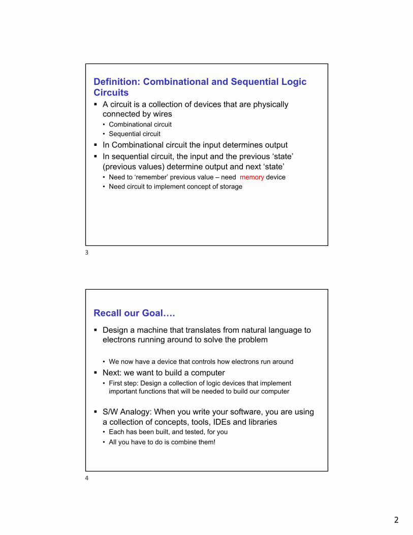
Definition: Combinational and Sequential Logic Circuits§ A circuit is a collection of devices that are physically
connected by wires• Combinational circuit• Sequential circuit
§ In Combinational circuit the input determines output§ In sequential circuit, the input and the previous ‘state’
(previous values) determine output and next ‘state’• Need to ‘remember’ previous value – need memory device• Need circuit to implement concept of storage
3
Recall our Goal….§ Design a machine that translates from natural language to
electrons running around to solve the problem
• We now have a device that controls how electrons run around§ Next: we want to build a computer
• First step: Design a collection of logic devices that implement important functions that will be needed to build our computer
§ S/W Analogy: When you write your software, you are using a collection of concepts, tools, IDEs and libraries• Each has been built, and tested, for you • All you have to do is combine them!
4

3
Combinational Logic Devices§ We saw how we can build the simple logic gates using
transistors and build any boolean function using these gates§ Use these gates as building blocks to build more complex
combinational circuits• Decoder: based on value of n-bit input control signal,
select one of 2N outputs• Multiplexer: based on value of N-bit input control signal,
select one of 2N inputs.• Adder: add two binary numbers• …any boolean function
§ SW Analogy: We are building a library of functions• To design your solution, you can use any device in the library!
5
Three Devices we focus on…§ N-bit Adder
• Can build Subtract using Adder§ Decoder
• Decode a bit string§ Multiplexer
• A channel selector
§ Other useful combinational logic devices• Multipliers• Shifters (but may need storage)• Comparators (to compare two numbers)• …
6

4
1. N-bit Adder§ Add two N-bit numbers, represented in 2’s complement§ Algorithm (for now): add corresponding bit positions, starting
with least significant position, and propagate the carry bit leftward.• In practice: there are faster algorithms• Big-Oh Analysis:
o To add N bit numbers how ‘far’ will the carry propagate ?
7
Binary Addition
§ Binary addition – just like base 10 (decimal) !• Add from right to left, propagating carry • Example using unsigned integers
10010 10010 01111+ 01001 + 01011 + 00001
carry
11011 11101 10000
(18)
(9)
(27)
(18)
(11)
(29)
(15)
(1)
(16)
Key Observation: We add one bit at a timetherefore, building block is a 1-bit adderUse 1-bit adder to build N-bit adder!
8

5
1-bit Adder§ Two inputs A, B and Two outputs: S
(sum) and Carry out (C)§ Truth table:
§ Problem?§ This works only for bit 0 where there is
no Carry-in• Called a half adder
§ In general, we can have a carry-in input, so 3 inputs are A,B,Cin (carry-in) and 2 outputs S, Cout (carry out)
A B S C0 0 0 00 1 1 01 0 1 01 1 0 1
9
Truth Table for Full-Adder
A B Carry In Out Carry Out0 0 0 0 00 0 1 1 00 1 0 1 00 1 1 0 11 0 0 1 01 0 1 0 11 1 0 0 11 1 1 1 1
10

6
Truth Table for Full-Adder
A B Carry In Out Carry Out0 0 0 0 00 0 1 1 00 1 0 1 00 1 1 0 11 0 0 1 01 0 1 0 11 1 0 0 11 1 1 1 1
11
N-bit Adder§ Use the building block of the full-adder to build N-bit adder
• Need to connect carry-out to carry-in of next significant bit
§ Example of 4-bit adder using 4 1-bit adders chained together (ripple carry adder)
12

7
How about a “subtractor?”§ Build a subtracter from out multi-bit adder
• Calculate A – B = A + –B• Negate B• Recall –B = NOT(B) + 1
B16
adder
CarryIn
S16
16+1
16
A16
Approach#1
adder S16
B16 16
A16 CarryIn
1
Question: Can we build a single circuit that cando either (add or subtract)?
Approach#2
We “carry in” a 1
(no longer need incrementer)
13
The Decoder§ Useful for recognizing a particular bit pattern of 0’s and 1’s§ Connection to Computer Organization:
• Program consists of instructions -- coded in binary (0’s and 1’s)• We want to look at a bit string for the instruction and determine what
the instruction iso Is it an ADD or a MULT or a GOTO or…..o each instruction is given a unique encoding & decoder looks at
the encoding and determines which ONE of the instructions the code corresponds to (i.e, which instruction has to be executed)
§ In S/W, a “case”/switch statement:• One of the cases will be evaluated depending on value of ‘input’
14

8
Switch (case) statement in Cint x;….switch(x) {
case 0: /* if x=0 call func Kevin */Kevin(); /* ex: Kevin does add */break;
case 1: /* if x=1 call func Graham */Graham();break;
case 2: /* if x=2 call func Sarah */Sarah(); /* ex: Sarah does AND */break;
case 3: /* if x=3 call func Linnea */Linnea();break;
default: printf(”invalid value of x”\n);break;
}..
15
N-2N Decoder§ N inputs – these represent the binary encoding of the 2N
Outputs• Ex: if N=2, then 4 outputs 0,1,2,3, encoded to be ‘switched on’ when
inputs are one of 00, 01, 10, 11 respectively
§ Schematic:
N
inputs2N outputs
Out 0
Out 2N-1
16

9
Designing a Decoder: Truth table 4 output lines x0,x1,x2,x3 & 2 inputs a1,a0
a1 a0 x0 x1 x2 x3
0 0 1 0 0 0
0 1 0 1 0 0
1 0 0 0 1 0
1 1 0 0 0 1
From truth table, design circuit:x0= a1’.a0’ (i.e., (NOT a1) AND (NOT a0))x1= a1’.a0 x2= a1.a0’ x3= a1.a0
17
Decoder
• An n input decoder has 2n outputs.
• Outputi is 1 iff the binary value of the n-bit input is i.
• At any time, exactly one output is 1, all others are 0.
1, iff A,B is 00AB
1, iff A,B is 01
1, iff A,B is 10 - Tim
1, iff A,B is 11
i = 0
i = 1
i = 2
i = 3
2-bit decoder(4 input decoder)
18

10
The Multiplexer - selector§ Multiplexer (MUX) is a device that selects one of the inputs
to be connected to the output• Similar to a channel selector
output
InputChannel 0
InputChannel 1
1
0
output=channel 1
1
0 output=channel 0
This is a 2-1 Multiplexer: Selects one of 2 inputs as the output
select input 1
select input 0
19
N-1 Multiplexer§ Multiplexer selects one of the N inputs as the output
• It needs log2 N ‘select lines’ to determine which of the N inputs is selected to appear at the output
• Schematic of a MUX:
§ Multi-bit muxes• Can switch an entire “bus” or group of signals• Switch n-bits with n muxes with the same select bits
S= Log N Select lines
OutputN inputs
S216
16
1616
16
20

11
3-21
The Multiplexer (MUX) – 2-1 and 4-1 MUX§ Selector/Chooser of signals – Imagine Switching Railroad Tracks
• Multi-way switch
0 12-to-1 Mux
002
012
102
112
4-to-1 Mux
S
OB
A
A
B
S=
O
Input “S” selects A or B to attach to “O” outputActs like an “IF/ELSE” statement
21
Multiplexer (MUX) • In general, a MUX haso2n data inputson select (or control) linesoand 1 output.
• It behaves like a channel selector.
A 4-to-1 MUX: Out takes the value of A,B, C or Ddepending on the value of S (00, 01, 10, 11)Out = A if S=00 Out = B if S = 01
Out = C if S=10 Out=D if S=11
S[1:0]
A B C D
Out
.S D.S S. C.S .S SB. S. SA. Out 10101010 +++=
A B C D
Out
S0
S1
Multiplexer (MUX) • In general, a MUX haso2n data inputson select (or control) linesoand 1 output.
• It behaves like a channel selector.
A 4-to-1 MUX: Out takes the value of A,B, C or Ddepending on the value of S (00, 01, 10, 11)Out = A if S=00 Out = B if S = 01
Out = C if S=10 Out=D if S=11
S[1:0]
A B C D
Out
.S D.S S. C.S .S SB. S. SA. Out 10101010 +++=
A B C D
Out
S0S1
Designing 4-1 MUX Using Logic Gates
22

12
Multiplexer (MUX) • In general, a MUX haso2n data inputson select (or control) linesoand 1 output.
• It behaves like a channel selector.
A 4-to-1 MUX: Out takes the value of A,B, C or Ddepending on the value of S (00, 01, 10, 11)Out = A if S=00 Out = B if S = 01
Out = C if S=10 Out=D if S=11
S[1:0]
A B C D
Out
.S D.S S. C.S .S SB. S. SA. Out 10101010 +++=
A B C D
Out
S0
S1
Multiplexer (MUX) • In general, a MUX haso2n data inputson select (or control) linesoand 1 output.
• It behaves like a channel selector.
A 4-to-1 MUX: Out takes the value of A,B, C or Ddepending on the value of S (00, 01, 10, 11)Out = A if S=00 Out = B if S = 01
Out = C if S=10 Out=D if S=11
S[1:0]
A B C D
Out
.S D.S S. C.S .S SB. S. SA. Out 10101010 +++=
A B C D
Out
S0S1
Designing 4-1 MUX Using Logic Gates
23
Example: MUX in a circuit§ Inputs A,,B,C and x (select signal); Output F§ Devices/Gates: 2-1 MUX, AND gate
§ If x=0, output of MUX = B and F= B.C§ If x=1, output of MUX = A and F = A.C§ Can write F = xAC + x’BC
A
x
B CF
0
24

13
Combinational vs. Sequential§Combinational Circuit
• always gives the same output for a given set of inputso ex: adder always generates sum and carry,
regardless of previous inputs
§Sequential Circuit• stores information• output depends on stored information (state) plus input
o so a given input might produce different outputs,depending on the stored information
• example: vending machineo Current total increases when you insert coinso output depends on previous state
• useful for building “memory” elements and “state machines”
25
Next . . Circuits with “memory”
§ First we need to build a device that can store a bit• Using our current ‘library’ of gates• Building memory follows
§ How to model sequential circuits/machines• Methodology for designing these machines: Finite state machine• Model as a directed graph
§ How to we “synchronize” and ”coordinate” the different pieces in the circuit….enter the CLOCK
§ can we use a sequential circuit to “control” how computations take place in a processor ?
§ Is a sequential circuit = Computer ?• Limitations of sequential machines..more in Foundations course
26

14
Appendix
27
Binary Arithmetic: Half Adder§ Logical Function: Half Adder, implement Carry Out:
HA SumA
B
CarryOut (Cout)
A B Sum Cout0 0 0 00 1 1 0
1 0 1 0
1 1 0 1
Half Adder’s Logic Function:SUM=((A’ AND B’) OR (A AND B))’C=( (A’ AND B’) OR (A’ AND B) OR (A AND B’) )’
Realize though: C= (A AND B), this isn’t always best way!
28

15
Addition: Full Adders§ There is a limit with the half adder
• It can’t implement multiple-bit addition
• It works for “least significant bit,” but won’t work for the next
• We need an adder that has 3 inputs and 2 outputs 3-29
HA SumA
B
CarryOut (Cout)
1+ 1
1 0
ABSumCout
1 1+ 1 1
1 1 0
AB
Sum
Cin
Cout
1
FA SumA
CarryIn
CarryOut
B
29
Truth Table
A B Carry In Out Carry Out0 0 0 0 00 0 1 1 00 1 0 1 00 1 1 0 11 0 0 1 01 0 1 0 11 1 0 0 11 1 1 1 1
30

16
Full Adder
A B
SUM-OUT
Carry INCarry OUT
31
1-bit Full Adder§Add two bits and carry-in,produce one-bit sum and carry-out. A B Cin S Cout
0 0 0 0 00 0 1 1 00 1 0 1 00 1 1 0 11 0 0 1 01 0 1 0 11 1 0 0 11 1 1 1 1
32

17
3-33
CarryInN-bit Adder
. . .
Add S0
A0
CarryIn0
CarryOut0B0
Add S1
A1
CarryIn1
CarryOut1B1
Add S2
A2
CarryIn2
CarryOut2B2
CarryIn
CarryOut
A
BS
1616
16
CarryOut: useful for detecting overflow
CarryIn: assumed to be zero if not present
+
33
Four-bit Adder
34

18
A multi function Arithmetic Unit§ In a CPU, we’d like to do BOTH addition and subtraction
• Can we give the CPU the ability to choose between two pieces of hardware?
• Yes! § Using a MUX to build a multifunction ALU
35
Building an ALU using MUXAdder/Subtracter - Approach #1
CarryIn
CarryOut
A
BS
1616
16
Adder
CarryInA
BS
1616
16 16
1
Subtracter
Adder/SubtracterA
B
1616
16
1616
1 16S
Add/Sub If Add/Sub = 0 then AddIf Add/Sub=1 then Sub
36

19
Adder/Subtracter - Approach #2 (Optimize HW)
CarryInA
BS
1616
16 16
1CarryIn
CarryOut
A
BS
1616
16
Adder Subtracter
Adder/Subtracter
CarryIn
S16A
16
16B 16
Add/Sub1
37
Analysis of Circuits§ Download Example Circuits
• In Cedar Logic: Set2.cdl• In Logisim: Set2.zip
o Contains multiple files, titled Set2-Page1, Set2-Page2, etc.o Pages correspond to pages in the Set2.cdl file
38

20
Analysis of circuits in file: Set2§ Page 1: Check truth table and identify behavior§ Page 2: Part of the circuit looks identical to Page1, but there is an
additional ‘output.• Check truth table and identify behavior
§ Page 3: This uses the circuit from Page2 and connects them (connects output of one circuit to input of next circuit).• Identify the function being implemented
§ Page 4: If we treat 1-bit Adders as a Combinational logic device, then we can construct any N-bit adder using these devices• Bottom of the page has a schematic for a 4-bit adder• Input uses a Hex keyboard to input a 4-bit number• Uses a 7 segment LED display to display the 4-bit output as a hex number.• Analogy with software design: Construct solution which utilizes functions
39
Analysis of circuits in file: Set2§ Page 5: Uses an adder, but adds some logic operations to the input X
before it is sent to the Adder: Therefore adding Y and f(X) to get output Z• Inputs use Hex keyboards to send in 4-bit numbers• Determine what is f(x) and then determine what function is being implemented.
§ Page 6: Examples of Multiplexer and Decoder§ Page 7: Circuit uses a multiplexer and gates
• As you set the different select lines to the multiplexer, determine what the output is• Determine the behavior of the circuit and its ‘function’
§ Page 8: Circuit uses Multiplexer, Adder• Check truth table and identify behavior
§ Page 9: Uses Decoder and Multiplexer• Determine values of select lines of multiplexer based on output of decoder
§ Page 10: Example using a comparator
40