Combination Starters, NEMA Style, 8538CT9701R1015
48
Combination Starters NEMA Style Catalog 8538CT9701R08/17 2017 Class 8538/8539, 8738/8739 CONTENTS Description . . . . . . . . . . . . . . . . . . . . . . . . . . . . . . . . . . . . . . . . . . . . . Page Non-Reversing Combination Starters—NEMA Style. . . . . . . . . . . . . . . . . . 3 Overload Protection. . . . . . . . . . . . . . . . . . . . . . . . . . . . . . . . . . . . . . . . . 5 Selection . . . . . . . . . . . . . . . . . . . . . . . . . . . . . . . . . . . . . . . . . . . . . . . . . 6 Approximate Dimensions and Shipping Weights. . . . . . . . . . . . . . . . . . 18 Panel Layout Drawings . . . . . . . . . . . . . . . . . . . . . . . . . . . . . . . . . . . . . 21 Reversing Combination Starters—NEMA Style . . . . . . . . . . . . . . . . . . . . 22 Overload Protection. . . . . . . . . . . . . . . . . . . . . . . . . . . . . . . . . . . . . . . . 23 Selection . . . . . . . . . . . . . . . . . . . . . . . . . . . . . . . . . . . . . . . . . . . . . . . . 24 Approximate Dimensions. . . . . . . . . . . . . . . . . . . . . . . . . . . . . . . . . . . . 33 Panel Layout Drawings . . . . . . . . . . . . . . . . . . . . . . . . . . . . . . . . . . . . . 33 Application Data . . . . . . . . . . . . . . . . . . . . . . . . . . . . . . . . . . . . . . . . . . . . 34 Factory Modifications . . . . . . . . . . . . . . . . . . . . . . . . . . . . . . . . . . . . . . . . 42 Interlocks and Control Transformers. . . . . . . . . . . . . . . . . . . . . . . . . . . . . 47 Coils and Other Accessories . . . . . . . . . . . . . . . . See catalog 9999CT9701 ™
Transcript of Combination Starters, NEMA Style, 8538CT9701R1015
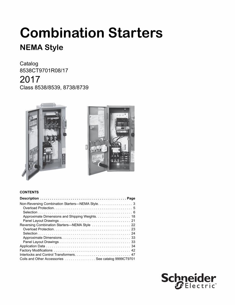
Combination StartersNEMA Style
Catalog8538CT9701R08/17
2017Class 8538/8539, 8738/8739
CONTENTS
Description . . . . . . . . . . . . . . . . . . . . . . . . . . . . . . . . . . . . . . . . . . . . . Page
Non-Reversing Combination Starters—NEMA Style. . . . . . . . . . . . . . . . . . 3Overload Protection. . . . . . . . . . . . . . . . . . . . . . . . . . . . . . . . . . . . . . . . . 5Selection . . . . . . . . . . . . . . . . . . . . . . . . . . . . . . . . . . . . . . . . . . . . . . . . . 6Approximate Dimensions and Shipping Weights. . . . . . . . . . . . . . . . . . 18Panel Layout Drawings . . . . . . . . . . . . . . . . . . . . . . . . . . . . . . . . . . . . . 21
Reversing Combination Starters—NEMA Style . . . . . . . . . . . . . . . . . . . . 22Overload Protection. . . . . . . . . . . . . . . . . . . . . . . . . . . . . . . . . . . . . . . . 23Selection . . . . . . . . . . . . . . . . . . . . . . . . . . . . . . . . . . . . . . . . . . . . . . . . 24Approximate Dimensions. . . . . . . . . . . . . . . . . . . . . . . . . . . . . . . . . . . . 33Panel Layout Drawings . . . . . . . . . . . . . . . . . . . . . . . . . . . . . . . . . . . . . 33
Application Data . . . . . . . . . . . . . . . . . . . . . . . . . . . . . . . . . . . . . . . . . . . . 34Factory Modifications . . . . . . . . . . . . . . . . . . . . . . . . . . . . . . . . . . . . . . . . 42Interlocks and Control Transformers. . . . . . . . . . . . . . . . . . . . . . . . . . . . . 47Coils and Other Accessories . . . . . . . . . . . . . . . . See catalog 9999CT9701
™

Combination StartersClass 8538, 8539—Non-Reversing—General Information
308/2017© 1998–2017 Schneider Electric
All Rights Reserved™
Non-Reversing Combination Starters, NEMA Style
General Information
Class 8538 and 8539 Type S combination starters combine the requirements of motor overload and short-circuit protection into one package. These starters are manufactured in accordance with NEMA standards and are UL Listed (although some Form numbers may not be listed—contact your local Square D™ representative for information). Class 8538 and 8539 combination starters are designed to operate at 600 Vac maximum, 50 to 60 Hz—and come standard with melting alloy overload relays. Bimetallic and solid-state overload relays are available as options (see pages 45–46).
Type 2 Coordination
Square D brand is one of the leaders in North America and Europe in providing starters that are verified by UL to comply with IEC 947-4-1 and Type 2 coordination. This means that the controller components—the contactor, the overload relay, and the motor branch circuit protective device (fuses or circuit breaker)—will be suitable for further use following a short-circuit fault (even though contact welding is recognized but can be easily broken). This allows for replacement of components during normal scheduled maintenance.
Square D starters and specified fuses have been tested by UL and CSA (at 100,000 A fault current) for operation at 600 Vac. Class 8538 Type S combination starters, NEMA Size 0–5, with fusible disconnect switches have tested to Type 2 performance criteria.
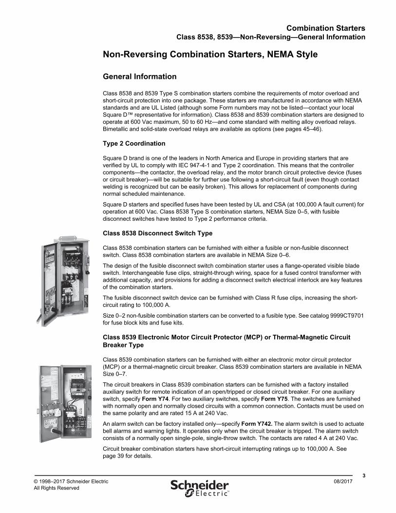
Class 8538 Disconnect Switch Type
Class 8538 combination starters can be furnished with either a fusible or non-fusible disconnect switch. Class 8538 combination starters are available in NEMA Size 0–6.
The design of the fusible disconnect switch combination starter uses a flange-operated visible blade switch. Interchangeable fuse clips, straight-through wiring, space for a fused control transformer with additional capacity, and provisions for adding a disconnect switch electrical interlock are key features of the combination starters.
The fusible disconnect switch device can be furnished with Class R fuse clips, increasing the short-circuit rating to 100,000 A.
Size 0–2 non-fusible combination starters can be converted to a fusible type. See catalog 9999CT9701 for fuse block kits and fuse kits.
Class 8539 Electronic Motor Circuit Protector (MCP) or Thermal-Magnetic Circuit Breaker Type
Class 8539 combination starters can be furnished with either an electronic motor circuit protector (MCP) or a thermal-magnetic circuit breaker. Class 8539 combination starters are available in NEMA Size 0–7.
The circuit breakers in Class 8539 combination starters can be furnished with a factory installed auxiliary switch for remote indication of an open/tripped or closed circuit breaker. For one auxiliary switch, specify Form Y74. For two auxiliary switches, specify Form Y75. The switches are furnished with normally open and normally closed circuits with a common connection. Contacts must be used on the same polarity and are rated 15 A at 240 Vac.
An alarm switch can be factory installed only—specify Form Y742. The alarm switch is used to actuate bell alarms and warning lights. It operates only when the circuit breaker is tripped. The alarm switch consists of a normally open single-pole, single-throw switch. The contacts are rated 4 A at 240 Vac.
Circuit breaker combination starters have short-circuit interrupting ratings up to 100,000 A. See page 39 for details.
Combination StartersClass 8538, 8539—Non-Reversing—General Information
408/2017 © 1998–2017 Schneider Electric
All Rights Reserved™
Enclosures—Class 8538 and 8539 combination starters are available in the following enclosures:
• NEMA 1 General Purpose
• NEMA 4 & 4X Watertight and Dusttight Stainless Steel
• NEMA 4X Watertight, Dusttight, and Corrosion Resistant Glass-Polyester
• NEMA 12/3R Dusttight and Driptight for Industrial Use
These enclosures have three holes (30.5 mm) as standard for installation of Class 9001 Type K push buttons, pilot lights, and other cover-mounted control units.
The NEMA 4 & 4X stainless steel enclosures (Sizes 0–5) have a brushed finish. Sizes 6–7 are painted sheet-steel enclosures and are rated NEMA 4 only. Hubs come standard on NEMA 4X enclosures.
NEMA 12 enclosures can be field modified for outdoor applications. Specify Form G26 for NEMA 3R (no additional charge). See page 19 for additional information.
Oversize Enclosures—Class 8538 disconnect switch type and Class 8539 electronic motor circuit protector (MCP), Sizes 0–2, are also available in NEMA 1, 4 & 4X, and 12/3R oversize enclosures. The oversize enclosures provide additional panel space for customer installation of control transformers, fuse blocks, terminal blocks, relays, and other auxiliary equipment.
Coil Voltages—AC coils are available for application at 50–60 Hz. The coils for NEMA Size 00–5 devices are designed to operate satisfactorily on line voltages of 85–110% of rated voltage. NEMA Size 6–7 contactors come with a DC coil operated by a solid-state rectifier circuit, which is powered by an AC source and designed to operate satisfactorily on line voltages of 90–110% of rated voltage.
NOTE: A voltage code is required when ordering combination starters. Polyphase combination starters with 24 Vac or 120 Vac coil voltages come wired for separate control.
Auxiliary Contacts—Additional auxiliary contacts can be added to Type S starters. Refer to page 37 for the maximum number of auxiliary units and the Form designations for factory-installed auxiliary contacts. See catalog 9999CT9701 for auxiliary contact kits for field installation.
Type S Accessories—Additional accessories such as fuse blocks, fuse clip kits, disconnect switch and circuit breaker interlocks, and cover-mounted control units are available as field modifications. See catalog 9999CT9701. For factory modifications (Forms), see page 42.

Combination StartersClass 8538, 8539—Non-Reversing—Overload Protection
508/2017© 1998–2017 Schneider Electric
All Rights Reserved™
Overload Protection
Type S magnetic starters are used for full-voltage starting and stopping of AC squirrel cage motors. Motor overload protection for three-phase starter applications can be provided through one of four options, as follows:
Solid-State Overload Relay Protection (Motor Logic™ SSOLR)—These ambient insensitive overload relays are available on Sizes 00–6 and standard on Size 7. They provide phase loss and phase unbalance protection. To order, add Form H30 (for selectable trip class 10 or 20 protection). For more information about Motor Logic SSOLRs, see page 45 and catalog 9065CT9701. (Product catalog number example: 8536SCO3V06H30)
Adapted Bimetallic Overload Relay (NEMA Sizes 00–1)—The adapted bimetallic motor starter consists of a specially designed adapter. It attaches with bus bars to the Type S NEMA contactor and holds the IEC-style bimetallic overload relay (type LRD or LR3D). This starter configuration can be ordered by adding Form E (adapter only) to the standard catalog number. The LRD or LR3D bimetallic overload relay must be purchased separately, based on the motor FLA, and installed in the field in order to operate the starter. For more information—including how to order the adapted bimetallic overload relay as a factory installed option—see page 45 and catalog 9065CT9701. (Product catalog number example: 8536SCO3V06E)
TeSys™ T Motor Management System (NEMA Sizes 1–6)—The flexible TeSys T system integrates seamlessly into your automation system through five major communication protocols. The TeSys T system can predict what will happen in the process, as it accurately monitors current, voltage, and power over a wide range. This option is available for control voltages of 24 Vac or 100–240 Vac. For additional information about the TeSys T Motor Management System, see page 46 and catalog 9065CT9701.
NOTE: The full catalog number contains a four-character Form number (for example, 8536SCO3V06H616).
Melting Alloy Thermal Overload Relays—Melting alloy type thermal overload blocks are installed as part of the starter, and thermal elements must be selected and installed separately in order to operate the starter. For a three-phase motor, three thermal units must be ordered using the tables in catalog 9065CT9701. The catalog number includes no Form number (for example, 8536SCO3V06).
Combination StartersClass 8538—Fusible Disconnect Switch Type
608/2017 © 1998–2017 Schneider Electric
All Rights Reserved™
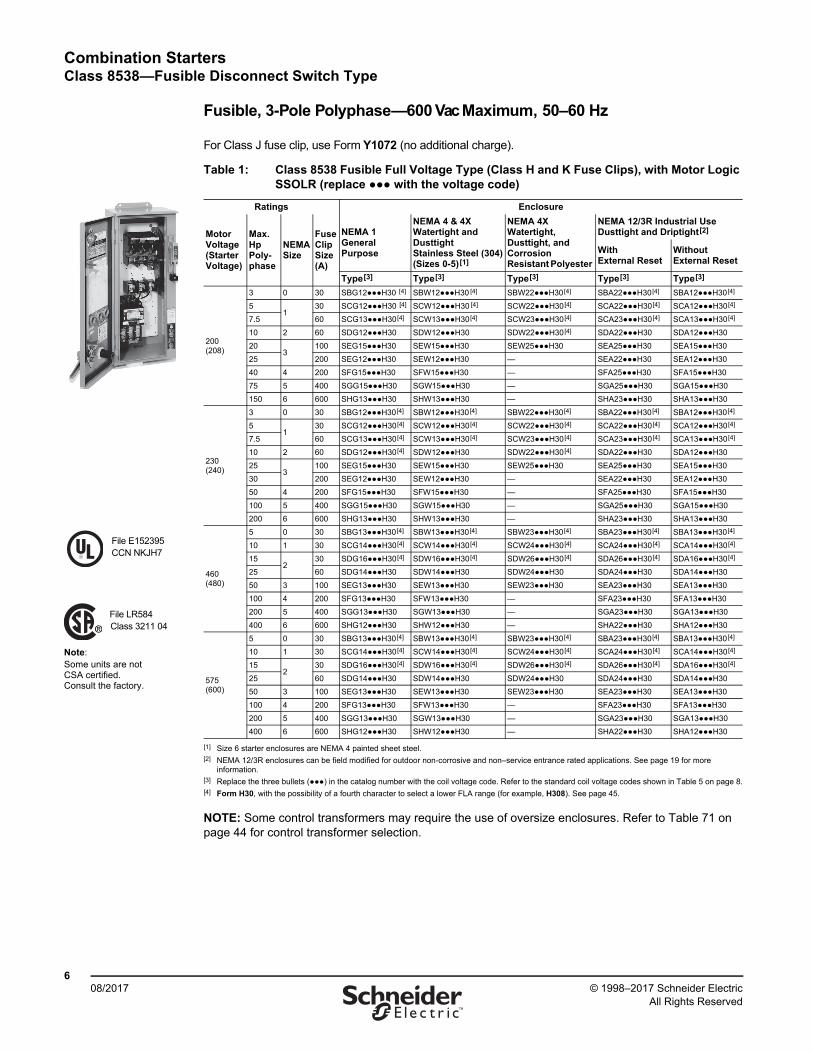
Fusible, 3-Pole Polyphase—600 Vac Maximum, 50–60 Hz
For Class J fuse clip, use Form Y1072 (no additional charge).
NOTE: Some control transformers may require the use of oversize enclosures. Refer to Table 71 on page 44 for control transformer selection.
Table 1: Class 8538 Fusible Full Voltage Type (Class H and K Fuse Clips), with Motor Logic SSOLR (replace ●●● with the voltage code)
Ratings Enclosure
Motor Voltage(Starter Voltage)
Max. HpPoly-phase
NEMA Size
FuseClipSize(A)
NEMA 1General Purpose
NEMA 4 & 4XWatertight and Dusttight Stainless Steel (304)(Sizes 0-5)[1]
[1] Size 6 starter enclosures are NEMA 4 painted sheet steel.
NEMA 4X Watertight, Dusttight, and Corrosion Resistant Polyester
NEMA 12/3R Industrial Use Dusttight and Driptight[2]
[2] NEMA 12/3R enclosures can be field modified for outdoor non-corrosive and non–service entrance rated applications. See page 19 for more information.
WithExternal Reset
WithoutExternal Reset
Type[3]
[3] Replace the three bullets (●●●) in the catalog number with the coil voltage code. Refer to the standard coil voltage codes shown in Table 5 on page 8.
Type[3] Type[3] Type[3] Type[3]
200(208)
3 0 30 SBG12●●●H30 [4]
[4] Form H30, with the possibility of a fourth character to select a lower FLA range (for example, H308). See page 45.
SBW12●●●H30 [4] SBW22●●●H30[4] SBA22●●●H30[4] SBA12●●●H30[4]
51
30 SCG12●●●H30 [4] SCW12●●●H30 [4] SCW22●●●H30[4] SCA22●●●H30[4] SCA12●●●H30[4]
7.5 60 SCG13●●●H30[4] SCW13●●●H30[4] SCW23●●●H30[4] SCA23●●●H30[4] SCA13●●●H30[4]
10 2 60 SDG12●●●H30 SDW12●●●H30 SDW22●●●H30[4] SDA22●●●H30 SDA12●●●H30
203
100 SEG15●●●H30 SEW15●●●H30 SEW25●●●H30 SEA25●●●H30 SEA15●●●H30
25 200 SEG12●●●H30 SEW12●●●H30 — SEA22●●●H30 SEA12●●●H30
40 4 200 SFG15●●●H30 SFW15●●●H30 — SFA25●●●H30 SFA15●●●H30
75 5 400 SGG15●●●H30 SGW15●●●H30 — SGA25●●●H30 SGA15●●●H30
150 6 600 SHG13●●●H30 SHW13●●●H30 — SHA23●●●H30 SHA13●●●H30
230(240)
3 0 30 SBG12●●●H30[4] SBW12●●●H30[4] SBW22●●●H30[4] SBA22●●●H30[4] SBA12●●●H30[4]
51
30 SCG12●●●H30[4] SCW12●●●H30[4] SCW22●●●H30[4] SCA22●●●H30[4] SCA12●●●H30[4]
7.5 60 SCG13●●●H30[4] SCW13●●●H30[4] SCW23●●●H30[4] SCA23●●●H30[4] SCA13●●●H30[4]
10 2 60 SDG12●●●H30[4] SDW12●●●H30 SDW22●●●H30[4] SDA22●●●H30 SDA12●●●H30
253
100 SEG15●●●H30 SEW15●●●H30 SEW25●●●H30 SEA25●●●H30 SEA15●●●H30
30 200 SEG12●●●H30 SEW12●●●H30 — SEA22●●●H30 SEA12●●●H30
50 4 200 SFG15●●●H30 SFW15●●●H30 — SFA25●●●H30 SFA15●●●H30
100 5 400 SGG15●●●H30 SGW15●●●H30 — SGA25●●●H30 SGA15●●●H30
200 6 600 SHG13●●●H30 SHW13●●●H30 — SHA23●●●H30 SHA13●●●H30
460(480)
5 0 30 SBG13●●●H30[4] SBW13●●●H30[4] SBW23●●●H30[4] SBA23●●●H30[4] SBA13●●●H30[4]
10 1 30 SCG14●●●H30[4] SCW14●●●H30[4] SCW24●●●H30[4] SCA24●●●H30[4] SCA14●●●H30[4]
152
30 SDG16●●●H30[4] SDW16●●●H30[4] SDW26●●●H30[4] SDA26●●●H30[4] SDA16●●●H30[4]
25 60 SDG14●●●H30 SDW14●●●H30 SDW24●●●H30 SDA24●●●H30 SDA14●●●H30
50 3 100 SEG13●●●H30 SEW13●●●H30 SEW23●●●H30 SEA23●●●H30 SEA13●●●H30
100 4 200 SFG13●●●H30 SFW13●●●H30 — SFA23●●●H30 SFA13●●●H30
200 5 400 SGG13●●●H30 SGW13●●●H30 — SGA23●●●H30 SGA13●●●H30
400 6 600 SHG12●●●H30 SHW12●●●H30 — SHA22●●●H30 SHA12●●●H30
575(600)
5 0 30 SBG13●●●H30[4] SBW13●●●H30[4] SBW23●●●H30[4] SBA23●●●H30[4] SBA13●●●H30[4]
10 1 30 SCG14●●●H30[4] SCW14●●●H30[4] SCW24●●●H30[4] SCA24●●●H30[4] SCA14●●●H30[4]
152
30 SDG16●●●H30[4] SDW16●●●H30[4] SDW26●●●H30[4] SDA26●●●H30[4] SDA16●●●H30[4]
25 60 SDG14●●●H30 SDW14●●●H30 SDW24●●●H30 SDA24●●●H30 SDA14●●●H30
50 3 100 SEG13●●●H30 SEW13●●●H30 SEW23●●●H30 SEA23●●●H30 SEA13●●●H30
100 4 200 SFG13●●●H30 SFW13●●●H30 — SFA23●●●H30 SFA13●●●H30
200 5 400 SGG13●●●H30 SGW13●●●H30 — SGA23●●●H30 SGA13●●●H30
400 6 600 SHG12●●●H30 SHW12●●●H30 — SHA22●●●H30 SHA12●●●H30
File E152395CCN NKJH7
File LR584Class 3211 04
Note: Some units are not CSA certified. Consult the factory.

Combination StartersClass 8538—Fusible Disconnect Switch Type
708/2017© 1998–2017 Schneider Electric
All Rights Reserved™
Non-Fusible, 3-Pole Polyphase—600 Vac Maximum, 50–60 Hz
Table 2: Class 8538 Fusible Disconnect Switch Type (Class H Fuse Clips), Single Phase [1], with Melting Alloy Overload Relay (see Thermal Unit Selection)
Ratings Enclosure
MotorVoltage
Max.Hp
CoilVoltage
NEMASize
Poles
Fuse Clip Size(A)
NEMA 1General Purpose
NEMA 4 & 4XWatertight and Dusttight Stainless Steel (304)
NEMA 4XWatertight, Dusttight, and Corrosion Resistant Polyester
NEMA 12/3R [2] Industrial UseDusttight and Driptight
WithExternal Reset
WithoutExternal Reset
Type Type Type Type Type
120
1
120
0
2
30 SBG62V02 SBW62V02 SBW65V02 SBA65V02 SBA62V02
2 1 30 SCG62V02 SCW62V02 SCW65V02 SCA65V02 SCA62V02
3 2 60 SDG62V02 SDW62V02 SDW65V02 SDA65V02 SDA62V02
240
2
240
0
2
30 SBG62V03 SBW62V03 SBW65V03 SBA65V03 SBA62V03
3 1 30 SCG62V03 SCW62V03 SCW65V03 SCA65V03 SCA62V03
7.5 2 60 SDG62V03 SDW62V03 SDW65V03 SDA65V03 SDA62V03
[1] Single-phase units require one thermal unit. They are not available with solid-state overload relays (Form H••).Not included in the Laser™ Delivery program.
[2] NEMA 12 enclosures can be field modified for outdoor non-corrosive and non–service entrance rated applications. See page 19 for more information.
Table 3: Class 8538 Non-Fusible Full Voltage Type, Non-Reversing, with Motor Logic SSOLR (replace ●●● with the voltage code)
Ratings Enclosure
Motor Voltage(Starter Voltage)
Max. HpPolyphase
NEMASize
NEMA 1General Purpose
NEMA 4 & 4XWatertight and Dusttight Stainless Steel (304) (Sizes 0–5) [1]
NEMA 4XWatertight, Dusttight, and Corrosion ResistantPolyester
NEMA 12/3R [2] Industrial UseDusttight and Driptight
WithExternal Reset
WithoutExternal Reset
Type [3] Type [3] Type [3] Type [3] Type [3]
200(208)
37.510254075150
0123456
SBG11●●●H30[4]
SCG11●●●H30[4]
SDG11●●●H30 SEG11●●●H30 SFG11●●●H30 SGG11●●●H30 SHG11●●●H30
SBW11●●●H30[4] SCW11●●●H30[4] SDW11●●●H30 SEW11●●●H30 SFW11●●●H30 SGW11●●●H30 SHW11●●●H30
SBW21●●●H30[4] SCW21●●●H30[4] SDW21●●●H30 SEW21●●●H30 ———
SBA21●●●H30[4] SCA21●●●H30[4] SDA21●●●H30 SEA21●●●H30 SFA21●●●H30 SGA21●●●H30 SHA21●●●H30
SBA11●●●H30[4] SCA11●●●H30[4] SDA11●●●H30 SEA11●●●H30 SFA11●●●H30 SGA11●●●H30 SHA11●●●H30
230(240)
37.5153050100200
0123456
SBG11●●●H30[4] SCG11●●●H30[4] SDG11●●●H30 SEG11●●●H30 SFG11●●●H30 SGG11●●●H30 SHG11●●●H30
SBW11●●●H30[4] SCW11●●●H30[4] SDW11●●●H30 SEW11●●●H30 SFW11●●●H30 SGW11●●●H30 SHW11●●●H30
SBW21●●●H30[4] SCW21●●●H30[4] SDW21●●●H30 SEW21●●●H30 ———
SBA21●●●H30[4] SCA21●●●H30[4] SDA21●●●H30 SEA21●●●H30 SFA21●●●H30 SGA21●●●H30 SHA21●●●H30
SBA11●●●H30[4] SCA11●●●H30[4] SDA11●●●H30 SEA11●●●H30 SFA11●●●H30 SGA11●●●H30 SHA11●●●H30
460(480)
5102550100200400
0123456
SBG11●●●H30[4] SCG11●●●H30[4] SDG11●●●H30 SEG11●●●H30 SFG11●●●H30 SGG11●●●H30 SHG11●●●H30
SBW11●●●H30[4] SCW11●●●H30[4] SDW11●●●H30 SEW11●●●H30 SFW11●●●H30 SGW11●●●H30 SHW11●●●H30
SBW21●●●H30[4]
SCW21●●●H30[4]
SDW21●●●H30 SEW21●●●H30 ———
SBA21●●●H30[4]
SCA21●●●H30[4]
SDA21●●●H30 SEA21●●●H30 SFA21●●●H30 SGA21●●●H30 SHA21●●●H30
SBA11●●●H30[4]
SCA11●●●H30[4]
SDA11●●●H30 SEA11●●●H30 SFA11●●●H30 SGA11●●●H30 SHA11●●●H30
575(600)
5102550100200400
0123456
SBG11●●●H30[4] SCG11●●●H30[4] SDG11●●●H30 SEG11●●●H30 SFG11●●●H30 SGG11●●●H30 SHG11●●●H30
SBW11●●●H30[4] SCW11●●●H30[4] SDW11●●●H30 SEW11●●●H30 SFW11●●●H30 SGW11●●●H30 SHW11●●●H30
SBW21●●●H30[4] SCW21●●●H30[4] SDW21●●●H30 SEW21●●●H30 ———
SBA21●●●H30[4] SCA21●●●H30[4] SDA21●●●H30 SEA21●●●H30 SFA21●●●H30 SGA21●●●H30 SHA21●●●H30
SBA11●●●H30[4] SCA11●●●H30[4] SDA11●●●H30 SEA11●●●H30 SFA11●●●H30 SGA11●●●H30 SHA11●●●H30
[1] Size 6 starter enclosures are NEMA 4 painted sheet steel.[2] NEMA 12/3R enclosures can be field modified for outdoor non-corrosive and non–service entrance rated applications. See page 19 for more information.[3] Replace the three bullets (●●●) in the catalog number with the coil voltage code. Refer to the standard coil voltage codes shown in Table 5 on page 8.[4] Form H30, with the possibility of a fourth character to select a lower FLA range (for example, H308). See page 45.
Combination StartersClass 8538—Fusible Disconnect Switch Type
808/2017 © 1998–2017 Schneider Electric
All Rights Reserved™
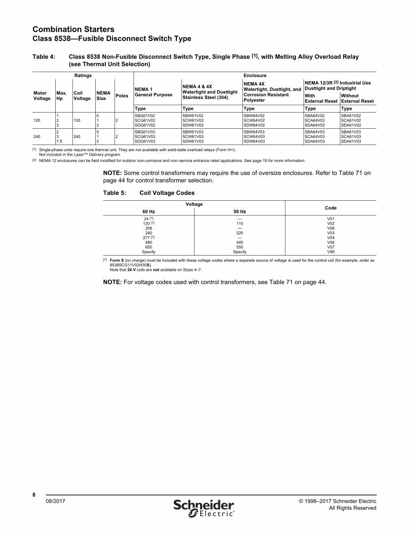
NOTE: Some control transformers may require the use of oversize enclosures. Refer to Table 71 on page 44 for control transformer selection.
NOTE: For voltage codes used with control transformers, see Table 71 on page 44.
Table 4: Class 8538 Non-Fusible Disconnect Switch Type, Single Phase [1], with Melting Alloy Overload Relay (see Thermal Unit Selection)
Ratings Enclosure
MotorVoltage
Max.Hp
CoilVoltage
NEMASize
PolesNEMA 1General Purpose
NEMA 4 & 4XWatertight and Dusttight Stainless Steel (304)
NEMA 4X Watertight, Dusttight, and Corrosion ResistantPolyester
NEMA 12/3R [2] Industrial Use Dusttight and Driptight
WithExternal Reset
WithoutExternal Reset
Type Type Type Type Type
120123
120012
2SBG61V02SCG61V02SDG61V02
SBW61V02SCW61V02SDW61V02
SBW64V02SCW64V02SDW64V02
SBA64V02SCA64V02SDA64V02
SBA61V02SCA61V02SDA61V02
240237.5
240012
2SBG61V03SCG61V03SDG61V03
SBW61V03SCW61V03SDW61V03
SBW64V03SCW64V03SDW64V03
SBA64V03SCA64V03SDA64V03
SBA61V03SCA61V03SDA61V03
[1] Single-phase units require one thermal unit. They are not available with solid-state overload relays (Form H••).Not included in the Laser™ Delivery program.
[2] NEMA 12 enclosures can be field modified for outdoor non-corrosive and non–service entrance rated applications. See page 19 for more information.
Table 5: Coil Voltage Codes
VoltageCode
60 Hz 50 Hz
24 [1]
120 [1]
208240
277 [1]
480600
Specify
[1] Form S (no charge) must be included with these voltage codes where a separate source of voltage is used for the control coil (for example, order as 8538SCG11V02H30S). Note that 24 V coils are not available on Sizes 4–7.
—110—
220—
440550
Specify
V01V02V08V03V04V06V07V99
Combination StartersClass 8538—Fusible Disconnect Switch Type with Class R Fuse Clips
908/2017© 1998–2017 Schneider Electric
All Rights Reserved™
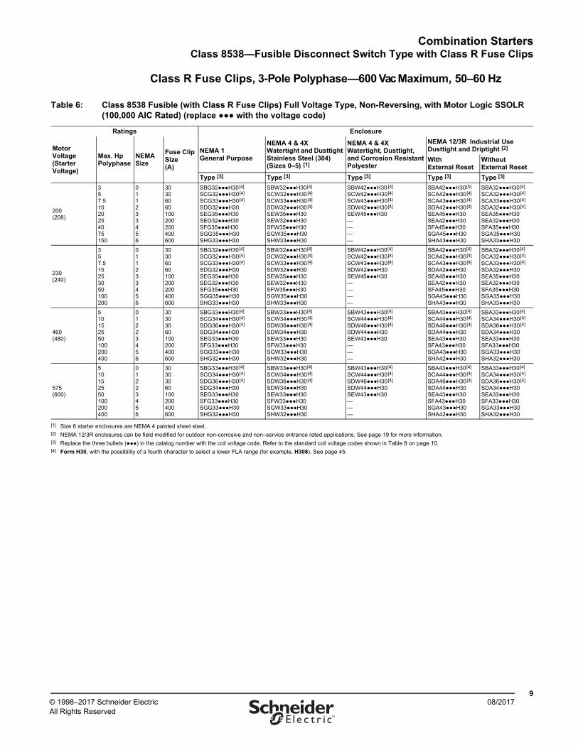
Class R Fuse Clips, 3-Pole Polyphase—600 Vac Maximum, 50–60 Hz
Table 6: Class 8538 Fusible (with Class R Fuse Clips) Full Voltage Type, Non-Reversing, with Motor Logic SSOLR (100,000 AIC Rated) (replace ●●● with the voltage code)
Ratings Enclosure
Motor Voltage(Starter Voltage)
Max. HpPolyphase
NEMA Size
Fuse ClipSize(A)
NEMA 1General Purpose
NEMA 4 & 4XWatertight and Dusttight Stainless Steel (304)(Sizes 0–5) [1]
NEMA 4 & 4XWatertight, Dusttight, and Corrosion ResistantPolyester
NEMA 12/3R Industrial UseDusttight and Driptight [2]
WithExternal Reset
WithoutExternal Reset
Type [3] Type [3] Type [3] Type [3] Type [3]
200(208)
357.51020254075150
011233456
30306060100200200400600
SBG32●●●H30[4]
SCG32●●●H30[4]
SCG33●●●H30[4]
SDG32●●●H30 SEG35●●●H30SEG32●●●H30SFG35●●●H30SGG35●●●H30SHG33●●●H30
SBW32●●●H30[4]
SCW32●●●H30[4]
SCW33●●●H30[4]
SDW32●●●H30[4]
SEW35●●●H30SEW32●●●H30SFW35●●●H30SGW35●●●H30SHW33●●●H30
SBW42●●●H30 [4]
SCW42●●●H30[4]
SCW43●●●H30[4]
SDW42●●●H30[4]
SEW45●●●H30 ————
SBA42●●●H30[4]
SCA42●●●H30[4]
SCA43●●●H30[4]
SDA42●●●H30[4]
SEA45●●●H30 SEA42●●●H30 SFA45●●●H30 SGA45●●●H30 SHA43●●●H30
SBA32●●●H30[4]
SCA32●●●H30[4]
SCA33●●●H30[4]
SDA32●●●H30[4]
SEA35●●●H30 SEA32●●●H30 SFA35●●●H30 SGA35●●●H30 SHA33●●●H30
230(240)
357.515253050100200
011233456
30306060100200200400600
SBG32●●●H30[4]
SCG32●●●H30[4]
SCG33●●●H30[4]
SDG32●●●H30 SEG35●●●H30 SEG32●●●H30 SFG35●●●H30 SGG35●●●H30 SHG33●●●H30
SBW32●●●H30[4]
SCW32●●●H30[4]
SCW33●●●H30[4]
SDW32●●●H30 SEW35●●●H30 SEW32●●●H30 SFW35●●●H30 SGW35●●●H30 SHW33●●●H30
SBW42●●●H30[4]
SCW42●●●H30[4]
SCW43●●●H30[4]
SDW42●●●H30 SEW45●●●H30 ————
SBA42●●●H30[4]
SCA42●●●H30[4]
SCA43●●●H30[4]
SDA42●●●H30 SEA45●●●H30 SEA42●●●H30 SFA45●●●H30 SGA45●●●H30 SHA43●●●H30
SBA32●●●H30[4]
SCA32●●●H30[4]
SCA33●●●H30[4]
SDA32●●●H30 SEA35●●●H30 SEA32●●●H30 SFA35●●●H30 SGA35●●●H30 SHA33●●●H30
460(480)
510152550100200400
01223456
30303060100200400600
SBG33●●●H30[4]
SCG34●●●H30[4]
SDG36●●●H30[4]
SDG34●●●H30 SEG33●●●H30 SFG33●●●H30 SGG33●●●H30 SHG32●●●H30
SBW33●●●H30[4]
SCW34●●●H30[4]
SDW36●●●H30[4]
SDW34●●●H30 SEW33●●●H30 SFW33●●●H30 SGW33●●●H30 SHW32●●●H30
SBW43●●●H30[4]
SCW44●●●H30[4]
SDW46●●●H30[4]
SDW44●●●H30 SEW43●●●H30 ———
SBA43●●●H30[4]
SCA44●●●H30[4]
SDA46●●●H30[4]
SDA44●●●H30 SEA43●●●H30 SFA43●●●H30 SGA43●●●H30 SHA42●●●H30
SBA33●●●H30[4]
SCA34●●●H30[4]
SDA36●●●H30[4]
SDA34●●●H30 SEA33●●●H30 SFA33●●●H30 SGA33●●●H30 SHA32●●●H30
575(600)
510152550100200400
01223456
30303060100200400600
SBG33●●●H30[4]
SCG34●●●H30[4]
SDG36●●●H30[4]
SDG34●●●H30 SEG33●●●H30 SFG33●●●H30 SGG33●●●H30 SHG32●●●H30
SBW33●●●H30[4]
SCW34●●●H30[4]
SDW36●●●H30[4]
SDW34●●●H30 SEW33●●●H30 SFW33●●●H30 SGW33●●●H30 SHW32●●●H30
SBW43●●●H30[4]
SCW44●●●H30[4]
SDW46●●●H30[4]
SDW44●●●H30 SEW43●●●H30 ———
SBA43●●●H30[4]
SCA44●●●H30[4]
SDA46●●●H30[4]
SDA44●●●H30 SEA43●●●H30 SFA43●●●H30 SGA43●●●H30 SHA42●●●H30
SBA33●●●H30[4]
SCA34●●●H30[4]
SDA36●●●H30[4]
SDA34●●●H30 SEA33●●●H30 SFA33●●●H30 SGA33●●●H30 SHA32●●●H30
[1] Size 6 starter enclosures are NEMA 4 painted sheet steel.[2] NEMA 12/3R enclosures can be field modified for outdoor non-corrosive and non–service entrance rated applications. See page 19 for more information.[3] Replace the three bullets (●●●) in the catalog number with the coil voltage code. Refer to the standard coil voltage codes shown in Table 8 on page 10.[4] Form H30, with the possibility of a fourth character to select a lower FLA range (for example, H308). See page 45.
Combination StartersClass 8538—Fusible Disconnect Switch Type with Class R Fuse Clips
1008/2017 © 1998–2017 Schneider Electric
All Rights Reserved™
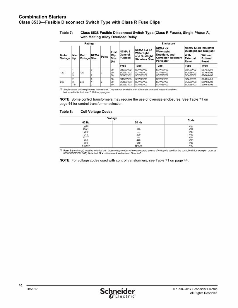
NOTE: Some control transformers may require the use of oversize enclosures. See Table 71 on page 44 for control transformer selection.
NOTE: For voltage codes used with control transformers, see Table 71 on page 44.
Table 7: Class 8538 Fusible Disconnect Switch Type (Class R Fuses), Single Phase [1], with Melting Alloy Overload Relay
[1] Single-phase units require one thermal unit. They are not available with solid-state overload relays (Form H••).Not included in the Laser™ Delivery program.
Ratings Enclosure
MotorVoltage
Max.Hp
CoilVoltage
NEMA Size
Poles
Fuse Clip Size(A)
NEMA 1General Purpose
NEMA 4 & 4XWatertightand DusttightStainless Steel
NEMA 4XWatertight, Dusttight, and Corrosion ResistantPolyester
NEMA 12/3R IndustrialDusttight and Driptight
WithExternal Reset
WithoutExternal Reset
Type Type Type Type Type
120123
120012
2303060
SBG63V02SCG63V02SDG63V02
SBW63V02SCW63V02SDW63V02
SBW66V02SCW66V02SDW66V02
SBA66V02SCA66V02SDA66V02
SBA63V02SCA63V02SDA63V02
240237.5
240012
2303060
SBG63V03SCG63V03SDG63V03
SBW63V03SCW63V03SDW63V03
SBW66V03SCW66V03SDW66V03
SBA66V03SCA66V03SDA66V03
SBA63V03SCA63V03SDA63V03
Table 8: Coil Voltage Codes
VoltageCode
60 Hz 50 Hz
24[1]
120[1]
208240
277[1]
480600
Specify
[1] Form S (no charge) must be included with these voltage codes where a separate source of voltage is used for the control coil (for example, order as 8538SCG32V02H30S). Note that 24 V coils are not available on Sizes 4–7.
—110—
220—
440550
Specify
V01V02V08V03V04V06V07V99
Combination StartersClass 8538—Disconnect Switch Type in Oversize Enclosure, NEMA Size 0–2
1108/2017© 1998–2017 Schneider Electric
All Rights Reserved™
Oversize Enclosures, 3-Pole Polyphase—600 Vac Maximum, 50–60 Hz
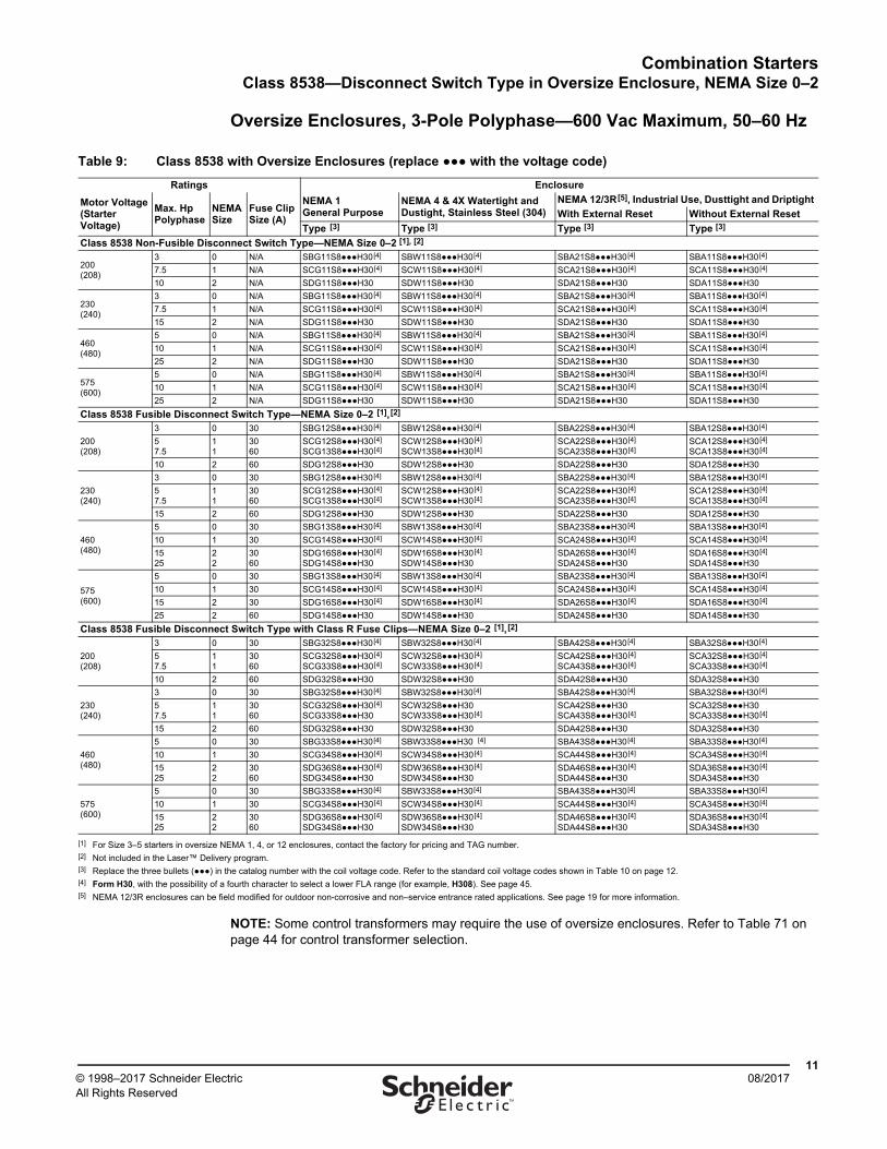
NOTE: Some control transformers may require the use of oversize enclosures. Refer to Table 71 on page 44 for control transformer selection.
Table 9: Class 8538 with Oversize Enclosures (replace ●●● with the voltage code)
Ratings Enclosure
Motor Voltage(Starter Voltage)
Max. HpPolyphase
NEMASize
Fuse ClipSize (A)
NEMA 1General Purpose
NEMA 4 & 4X Watertight and Dustight, Stainless Steel (304)
NEMA 12/3R[5], Industrial Use, Dusttight and Driptight
With External Reset Without External Reset
Type [3] Type [3] Type [3] Type [3]
Class 8538 Non-Fusible Disconnect Switch Type—NEMA Size 0–2 [1], [2]
200(208)
3 0 N/A SBG11S8●●●H30[4] SBW11S8●●●H30[4] SBA21S8●●●H30[4] SBA11S8●●●H30[4]
7.5 1 N/A SCG11S8●●●H30[4] SCW11S8●●●H30[4] SCA21S8●●●H30[4] SCA11S8●●●H30[4]
10 2 N/A SDG11S8●●●H30 SDW11S8●●●H30 SDA21S8●●●H30 SDA11S8●●●H30
230(240)
3 0 N/A SBG11S8●●●H30[4] SBW11S8●●●H30[4] SBA21S8●●●H30[4] SBA11S8●●●H30[4]
7.5 1 N/A SCG11S8●●●H30[4] SCW11S8●●●H30[4] SCA21S8●●●H30[4] SCA11S8●●●H30[4]
15 2 N/A SDG11S8●●●H30 SDW11S8●●●H30 SDA21S8●●●H30 SDA11S8●●●H30
460(480)
5 0 N/A SBG11S8●●●H30[4] SBW11S8●●●H30[4] SBA21S8●●●H30[4] SBA11S8●●●H30[4]
10 1 N/A SCG11S8●●●H30[4] SCW11S8●●●H30[4] SCA21S8●●●H30[4] SCA11S8●●●H30[4]
25 2 N/A SDG11S8●●●H30 SDW11S8●●●H30 SDA21S8●●●H30 SDA11S8●●●H30
575(600)
5 0 N/A SBG11S8●●●H30[4] SBW11S8●●●H30[4] SBA21S8●●●H30[4] SBA11S8●●●H30[4]
10 1 N/A SCG11S8●●●H30[4] SCW11S8●●●H30[4] SCA21S8●●●H30[4] SCA11S8●●●H30[4]
25 2 N/A SDG11S8●●●H30 SDW11S8●●●H30 SDA21S8●●●H30 SDA11S8●●●H30
Class 8538 Fusible Disconnect Switch Type—NEMA Size 0–2 [1],[2]
200(208)
3 0 30 SBG12S8●●●H30[4] SBW12S8●●●H30[4] SBA22S8●●●H30[4] SBA12S8●●●H30[4]
57.5
11
3060
SCG12S8●●●H30[4]
SCG13S8●●●H30[4] SCW12S8●●●H30[4]
SCW13S8●●●H30[4] SCA22S8●●●H30[4]
SCA23S8●●●H30[4] SCA12S8●●●H30[4]
SCA13S8●●●H30[4]
10 2 60 SDG12S8●●●H30 SDW12S8●●●H30 SDA22S8●●●H30 SDA12S8●●●H30
230(240)
3 0 30 SBG12S8●●●H30[4] SBW12S8●●●H30[4] SBA22S8●●●H30[4] SBA12S8●●●H30[4]
57.5
11
3060
SCG12S8●●●H30[4]
SCG13S8●●●H30[4] SCW12S8●●●H30[4]
SCW13S8●●●H30[4] SCA22S8●●●H30[4]
SCA23S8●●●H30[4] SCA12S8●●●H30[4]
SCA13S8●●●H30[4]
15 2 60 SDG12S8●●●H30 SDW12S8●●●H30 SDA22S8●●●H30 SDA12S8●●●H30
460(480)
5 0 30 SBG13S8●●●H30[4] SBW13S8●●●H30[4] SBA23S8●●●H30[4] SBA13S8●●●H30[4]
10 1 30 SCG14S8●●●H30[4] SCW14S8●●●H30[4] SCA24S8●●●H30[4] SCA14S8●●●H30[4]
1525
22
3060
SDG16S8●●●H30[4]
SDG14S8●●●H30SDW16S8●●●H30[4]
SDW14S8●●●H30 SDA26S8●●●H30[4]
SDA24S8●●●H30 SDA16S8●●●H30[4]
SDA14S8●●●H30
575(600)
5 0 30 SBG13S8●●●H30[4] SBW13S8●●●H30[4] SBA23S8●●●H30[4] SBA13S8●●●H30[4]
10 1 30 SCG14S8●●●H30[4] SCW14S8●●●H30[4] SCA24S8●●●H30[4] SCA14S8●●●H30[4]
15 2 30 SDG16S8●●●H30[4] SDW16S8●●●H30[4] SDA26S8●●●H30[4] SDA16S8●●●H30[4]
25 2 60 SDG14S8●●●H30 SDW14S8●●●H30 SDA24S8●●●H30 SDA14S8●●●H30
Class 8538 Fusible Disconnect Switch Type with Class R Fuse Clips—NEMA Size 0–2 [1],[2]
200(208)
3 0 30 SBG32S8●●●H30[4] SBW32S8●●●H30[4] SBA42S8●●●H30[4] SBA32S8●●●H30[4]
57.5
11
3060
SCG32S8●●●H30[4]
SCG33S8●●●H30[4] SCW32S8●●●H30[4]
SCW33S8●●●H30[4] SCA42S8●●●H30[4]
SCA43S8●●●H30[4] SCA32S8●●●H30[4]
SCA33S8●●●H30[4]
10 2 60 SDG32S8●●●H30 SDW32S8●●●H30 SDA42S8●●●H30 SDA32S8●●●H30
230(240)
3 0 30 SBG32S8●●●H30[4] SBW32S8●●●H30[4] SBA42S8●●●H30[4] SBA32S8●●●H30[4]
57.5
11
3060
SCG32S8●●●H30[4]
SCG33S8●●●H30 SCW32S8●●●H30 SCW33S8●●●H30[4]
SCA42S8●●●H30SCA43S8●●●H30[4]
SCA32S8●●●H30SCA33S8●●●H30[4]
15 2 60 SDG32S8●●●H30 SDW32S8●●●H30 SDA42S8●●●H30 SDA32S8●●●H30
460(480)
5 0 30 SBG33S8●●●H30[4] SBW33S8●●●H30 [4] SBA43S8●●●H30[4] SBA33S8●●●H30[4]
10 1 30 SCG34S8●●●H30[4] SCW34S8●●●H30[4] SCA44S8●●●H30[4] SCA34S8●●●H30[4]
1525
22
3060
SDG36S8●●●H30[4]
SDG34S8●●●H30 SDW36S8●●●H30[4]
SDW34S8●●●H30 SDA46S8●●●H30[4]
SDA44S8●●●H30 SDA36S8●●●H30[4]
SDA34S8●●●H30
575(600)
5 0 30 SBG33S8●●●H30[4] SBW33S8●●●H30[4] SBA43S8●●●H30[4] SBA33S8●●●H30[4]
10 1 30 SCG34S8●●●H30[4] SCW34S8●●●H30[4] SCA44S8●●●H30[4] SCA34S8●●●H30[4]
1525
22
3060
SDG36S8●●●H30[4]
SDG34S8●●●H30 SDW36S8●●●H30[4]
SDW34S8●●●H30 SDA46S8●●●H30[4]
SDA44S8●●●H30 SDA36S8●●●H30[4]
SDA34S8●●●H30
[1] For Size 3–5 starters in oversize NEMA 1, 4, or 12 enclosures, contact the factory for pricing and TAG number.[2] Not included in the Laser™ Delivery program.[3] Replace the three bullets (●●●) in the catalog number with the coil voltage code. Refer to the standard coil voltage codes shown in Table 10 on page 12.[4] Form H30, with the possibility of a fourth character to select a lower FLA range (for example, H308). See page 45. [5] NEMA 12/3R enclosures can be field modified for outdoor non-corrosive and non–service entrance rated applications. See page 19 for more information.
Combination StartersClass 8538—Disconnect Switch Type in Oversize Enclosure, NEMA Size 0–2
1208/2017 © 1998–2017 Schneider Electric
All Rights Reserved™
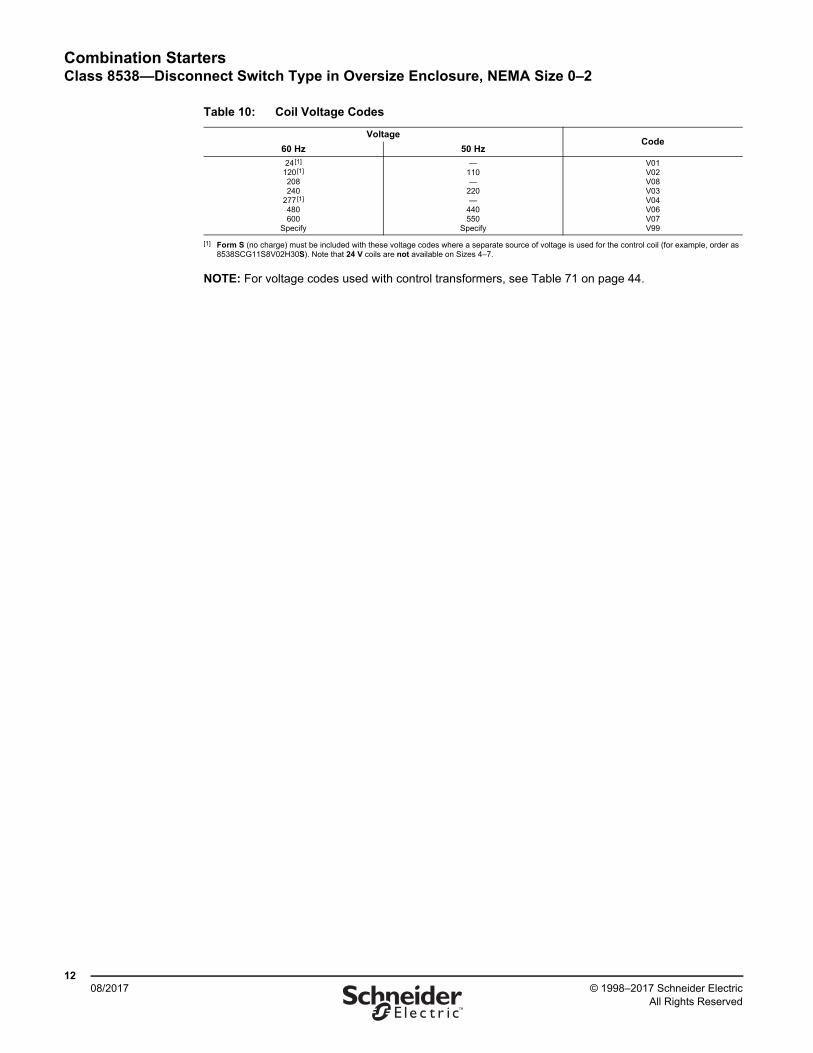
NOTE: For voltage codes used with control transformers, see Table 71 on page 44.
Table 10: Coil Voltage Codes
VoltageCode
60 Hz 50 Hz
24[1]
120[1]
208240
277[1]
480600
Specify
[1] Form S (no charge) must be included with these voltage codes where a separate source of voltage is used for the control coil (for example, order as 8538SCG11S8V02H30S). Note that 24 V coils are not available on Sizes 4–7.
—110—
220—
440550
Specify
V01V02V08V03V04V06V07V99
Combination StartersClass 8539—Electronic Motor Ciruit Protectot (MCP)
1308/2017© 1998–2017 Schneider Electric
All Rights Reserved™
Electronic MCP, 3-Pole Polyphase—600 Vac Maximum, 50–60 Hz
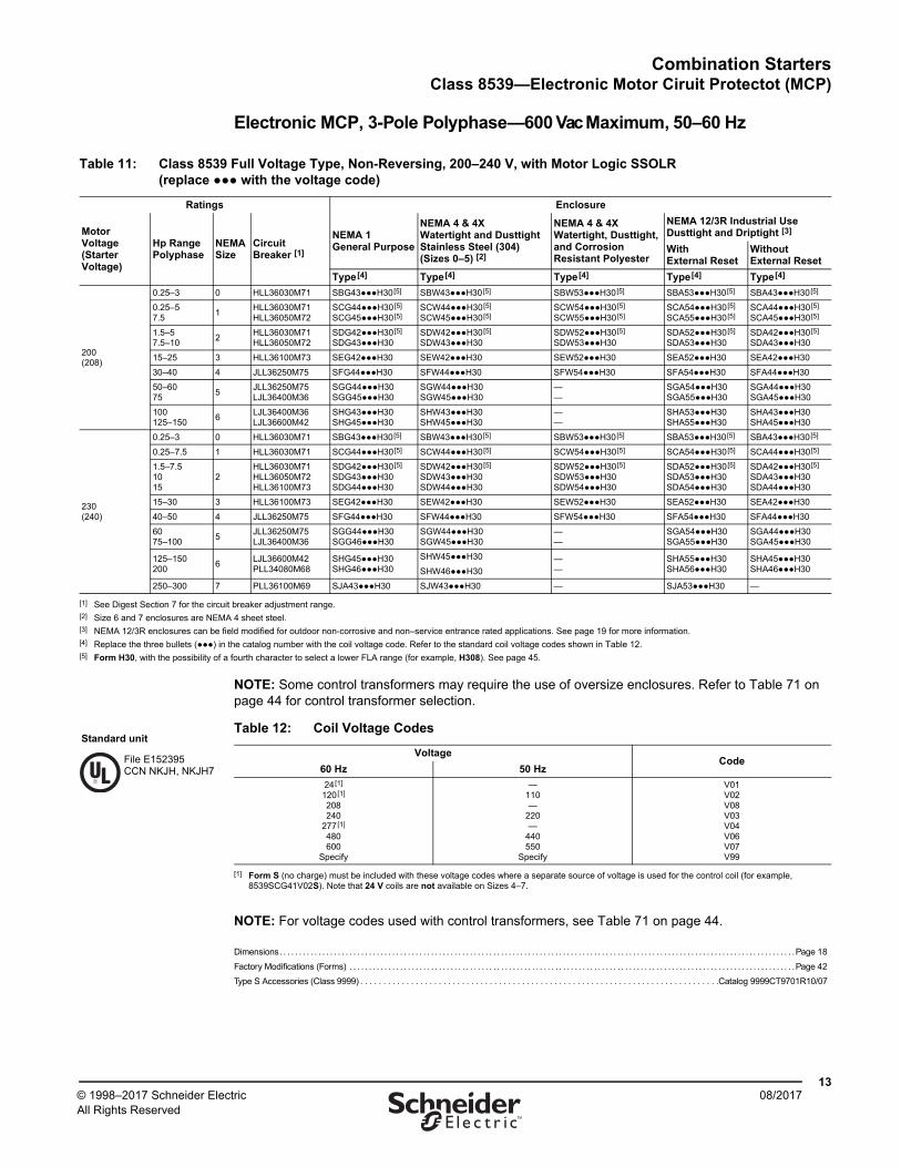
NOTE: Some control transformers may require the use of oversize enclosures. Refer to Table 71 on page 44 for control transformer selection.
NOTE: For voltage codes used with control transformers, see Table 71 on page 44.
Dimensions. . . . . . . . . . . . . . . . . . . . . . . . . . . . . . . . . . . . . . . . . . . . . . . . . . . . . . . . . . . . . . . . . . . . . . . . . . . . . . . . . . . . . . . . . . . . . . . . . . . . . . . . . . . . . . . . . . . . . . . . . . . . . . . . . . . . .Page 18
Factory Modifications (Forms) . . . . . . . . . . . . . . . . . . . . . . . . . . . . . . . . . . . . . . . . . . . . . . . . . . . . . . . . . . . . . . . . . . . . . . . . . . . . . . . . . . . . . . . . . . . . . . . . . . . . . . . . . . . . . . . . . . .Page 42
Type S Accessories (Class 9999) . . . . . . . . . . . . . . . . . . . . . . . . . . . . . . . . . . . . . . . . . . . . . . . . . . . . . . . . . . . . . . . . . . . . . . . . . . . . . .Catalog 9999CT9701R10/07
Table 11: Class 8539 Full Voltage Type, Non-Reversing, 200–240 V, with Motor Logic SSOLR (replace ●●● with the voltage code)
Ratings Enclosure
Motor Voltage(Starter Voltage)
Hp RangePolyphase
NEMA Size
Circuit Breaker [1]
NEMA 1General Purpose
NEMA 4 & 4XWatertight and Dusttight Stainless Steel (304)(Sizes 0–5) [2]
NEMA 4 & 4XWatertight, Dusttight, and Corrosion Resistant Polyester
NEMA 12/3R Industrial UseDusttight and Driptight [3]
WithExternal Reset
WithoutExternal Reset
Type[4] Type[4] Type[4] Type[4] Type[4]
200(208)
0.25–3 0 HLL36030M71 SBG43●●●H30[5] SBW43●●●H30[5] SBW53●●●H30[5] SBA53●●●H30[5] SBA43●●●H30[5]
0.25–57.5
1HLL36030M71HLL36050M72
SCG44●●●H30[5] SCG45●●●H30[5]
SCW44●●●H30[5] SCW45●●●H30[5]
SCW54●●●H30[5] SCW55●●●H30[5]
SCA54●●●H30[5] SCA55●●●H30[5]
SCA44●●●H30[5] SCA45●●●H30[5]
1.5–57.5–10
2HLL36030M71HLL36050M72
SDG42●●●H30[5] SDG43●●●H30
SDW42●●●H30[5] SDW43●●●H30
SDW52●●●H30[5] SDW53●●●H30
SDA52●●●H30[5] SDA53●●●H30
SDA42●●●H30[5] SDA43●●●H30
15–25 3 HLL36100M73 SEG42●●●H30 SEW42●●●H30 SEW52●●●H30 SEA52●●●H30 SEA42●●●H30
30–40 4 JLL36250M75 SFG44●●●H30 SFW44●●●H30 SFW54●●●H30 SFA54●●●H30 SFA44●●●H30
50–6075
5JLL36250M75LJL36400M36
SGG44●●●H30 SGG45●●●H30
SGW44●●●H30SGW45●●●H30
——
SGA54●●●H30 SGA55●●●H30
SGA44●●●H30 SGA45●●●H30
100125–150
6LJL36400M36LJL36600M42
SHG43●●●H30 SHG45●●●H30
SHW43●●●H30 SHW45●●●H30
——
SHA53●●●H30 SHA55●●●H30
SHA43●●●H30 SHA45●●●H30
230(240)
0.25–3 0 HLL36030M71 SBG43●●●H30[5] SBW43●●●H30[5] SBW53●●●H30[5] SBA53●●●H30[5] SBA43●●●H30[5]
0.25–7.5 1 HLL36030M71 SCG44●●●H30[5] SCW44●●●H30[5] SCW54●●●H30[5] SCA54●●●H30[5] SCA44●●●H30[5]
1.5–7.51015
2HLL36030M71HLL36050M72HLL36100M73
SDG42●●●H30[5] SDG43●●●H30 SDG44●●●H30
SDW42●●●H30[5] SDW43●●●H30 SDW44●●●H30
SDW52●●●H30[5] SDW53●●●H30 SDW54●●●H30
SDA52●●●H30[5] SDA53●●●H30 SDA54●●●H30
SDA42●●●H30[5] SDA43●●●H30 SDA44●●●H30
15–30 3 HLL36100M73 SEG42●●●H30 SEW42●●●H30 SEW52●●●H30 SEA52●●●H30 SEA42●●●H30
40–50 4 JLL36250M75 SFG44●●●H30 SFW44●●●H30 SFW54●●●H30 SFA54●●●H30 SFA44●●●H30
6075–100
5JLL36250M75LJL36400M36
SGG44●●●H30 SGG46●●●H30
SGW44●●●H30SGW45●●●H30
——
SGA54●●●H30SGA55●●●H30
SGA44●●●H30SGA45●●●H30
125–150200
6LJL36600M42PLL34080M68
SHG45●●●H30 SHG46●●●H30
SHW45●●●H30
SHW46●●●H30
——
SHA55●●●H30SHA56●●●H30
SHA45●●●H30SHA46●●●H30
250–300 7 PLL36100M69 SJA43●●●H30 SJW43●●●H30 — SJA53●●●H30 —
[1] See Digest Section 7 for the circuit breaker adjustment range.[2] Size 6 and 7 enclosures are NEMA 4 sheet steel.[3] NEMA 12/3R enclosures can be field modified for outdoor non-corrosive and non–service entrance rated applications. See page 19 for more information.[4] Replace the three bullets (●●●) in the catalog number with the coil voltage code. Refer to the standard coil voltage codes shown in Table 12.[5] Form H30, with the possibility of a fourth character to select a lower FLA range (for example, H308). See page 45.
Table 12: Coil Voltage Codes
VoltageCode
60 Hz 50 Hz
24[1]
120[1]
208240
277[1]
480600
Specify
[1] Form S (no charge) must be included with these voltage codes where a separate source of voltage is used for the control coil (for example, 8539SCG41V02S). Note that 24 V coils are not available on Sizes 4–7.
—110—
220—
440550
Specify
V01V02V08V03V04V06V07V99
File E152395CCN NKJH, NKJH7
Standard unit
Combination StartersClass 8539—Electronic Motor Circuit Protector (MCP)
1408/2017 © 1998–2017 Schneider Electric
All Rights Reserved™
Electronic MCP, 3-Pole Polyphase—600 Vac Maximum, 50–60 Hz
NOTE: Some control transformers may require the use of oversize enclosures. Refer to Table 71 on page 44 for control transformer selection.
NOTE: For voltage codes used with control transformers, see Table 71 on page 44.
Dimensions . . . . . . . . . . . . . . . . . . . . . . . . . . . . . . . . . . . . . . . . . . . . . . . . . . . . . . . . . . . . . . . . . . . . . . . . . . . . . . . . . . . . . . . . . . . . . . . . . . . . . . . . . . . . . . . . . . . . . . . . . . . . . . . . . . . . . .Page 18
Factory Modifications (Forms) . . . . . . . . . . . . . . . . . . . . . . . . . . . . . . . . . . . . . . . . . . . . . . . . . . . . . . . . . . . . . . . . . . . . . . . . . . . . . . . . . . . . . . . . . . . . . . . . . . . . . . . . . . . . . . . . . . . .Page 42
Type S Accessories (Class 9999). . . . . . . . . . . . . . . . . . . . . . . . . . . . . . . . . . . . . . . . . . . . . . . . . . . . . . . . . . . . . . . . . . . . . . . . . . . . . . Catalog 9999CT9701R10/07
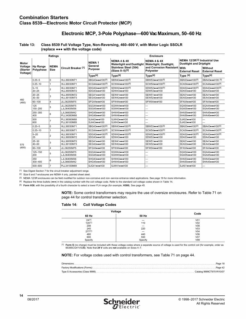
Table 13: Class 8539 Full Voltage Type, Non-Reversing, 460–600 V, with Motor Logic SSOLR (replace ●●● with the voltage code)
Ratings Enclosure
MotorVoltage(StarterVoltage)
Hp RangePolyphase
NEMASize
Circuit Breaker [1]
NEMA 1General Purpose
NEMA 4 & 4XWatertight and Dusttight Stainless Steel (304)(Sizes 0–5)[2]
NEMA 4 & 4XWatertight, Dusttight, and Corrosion ResistantPolyester
NEMA 12/3R[3] Industrial Use Dusttight and Driptight
WithExternal Reset
WithoutExternal Reset
Type[4] Type[4] Type[4] Type [4] Type[4]
460(480)
0.25–5 0 HLL36030M71 SBG43●●●H30[5] SBW43●●●H30[5] SBW53●●●H30[5] SBA53●●●H30[5] SBA43●●●H30 [5]
0.25–10 1 HLL36030M71 SCG44●●●H30[5] SCW44●●●H30[5] SCW54●●●H30[5] SCA54●●●H30[5] SCA44●●●H30[5]
5–1520–25
2HLL36030M71HLL36050M72
SDG42●●●H30[5] SDG43●●●H30
SDW42●●●H30[5] SDW43●●●H30
SDW52●●●H30[5] SDW53●●●H30
SDA52●●●H30[5] SDA53●●●H30
SDA42●●●H30[5] SDA43●●●H30
20–2530–50
3HLL36050M72HLL36100M73
SEG41●●●H30 SEG42●●●H30
SEW41●●●H30 SEW42●●●H30
SEW51●●●H30 SEW52●●●H30
SEA51●●●H30 SEA52●●●H30
SEA41●●●H30 SEA42●●●H30
60–100 4 JLL36250M75 SFG44●●●H30 SFW44●●●H30 SFW54●●●H30 SFA54●●●H30 SFA44●●●H30
125150–200
5JLL36250M75LJL36400M36
SGG44●●●H30 SGG45●●●H30
SGW44●●●H30 SGW45●●●H30
——
SGA54●●●H30 SGA55●●●H30
SGA44●●●H30 SGA45●●●H30
250–350400
6LJL36600M42PLL34080M68
SHG45●●●H30 SHG46●●●H30
SHW45●●●H30 SHW46●●●H30
——
SHA55●●●H30 SHA56●●●H30
SHA45●●●H30 SHA46●●●H30
500600
7PLL36080M68PLL36100M69
SJA42●●●H30 SJA43●●●H30
SJW42●●●H30 SJW43●●●H30
——
SJA52●●●H30 SJA53●●●H30
——
575(600)
0.25–5 0 HLL36030M71 SBG43●●●H30[5] SBW43●●●H30[5] SBW53●●●H30[5] SBA53●●●H30[5] SBA43●●●H30[5]
0.25–10 1 HLL36030M71 SCG44●●●H30[5] SCW44●●●H30[5] SCW54●●●H30[5] SCA54●●●H30[5] SCA44●●●H30[5]
5–2025
2HLL36030M71HLL36050M72
SDG42●●●H30[5] SDG43●●●H30
SDW42●●●H30[5] SDW43●●●H30
SDW52●●●H30[5] SDW53●●●H30
SDA52●●●H30[5] SDA53●●●H30
SDA42●●●H30[5] SDA43●●●H30
25–3040–50
3HLL36050M72HLL36100M73
SEG41●●●H30 SEG42●●●H30
SEW41●●●H30 SEW42●●●H30
SEW51●●●H30 SEW52●●●H30
SEA51●●●H30 SEA52●●●H30
SEA41●●●H30 SEA42●●●H30
60–100 4 JLL36250M75 SFG44●●●H30 SFW44●●●H30 SFW54●●●H30 SFA54●●●H30 SFA44●●●H30
125–150200
5JLL36250M75LJL36400M36
SGG44●●●H30 SGG45●●●H30
SGW44●●●H30 SGW45●●●H30
——
SGA54●●●H30 SGA55●●●H30
SGA44●●●H30 SGA45●●●H30
250300–400
6LJL36400M36LJL36600M42
SHG43●●●H30 SHG45●●●H30
SHW43●●●H30 SHW45●●●H30
——
SHA53●●●H30 SHA55●●●H30
SHA43●●●H30 SHA45●●●H30
500–600 7 PLL34100M69 SJG41●●●H30 SJW41●●●H30 — SJA51●●●H30 —
[1] See Digest Section 7 for the circuit breaker adjustment range.[2] Size 6 and 7 enclosures are NEMA 4 only, painted sheet steel.[3] NEMA 12/3R enclosures can be field modified for outdoor non-corrosive and non–service entrance rated applications. See page 19 for more information.[4] Replace the three bullets (●●●) in the catalog number with the coil voltage code. Refer to the standard coil voltage codes shown in Table 14.[5] Form H30, with the possibility of a fourth character to select a lower FLA range (for example, H308). See page 45.
Table 14: Coil Voltage Codes
VoltageCode
60 Hz 50 Hz
24[1]
120[1]
208240
277[1]
480600
Specify
[1] Form S (no charge) must be included with these voltage codes where a separate source of voltage is used for the control coil (for example, order as 8539SCG41V02S). Note that 24 V coils are not available on Sizes 4–7.
—110—
220—
440550
Specify
V01V02V08V03V04V06V07V99
Combination StartersClass 8539—Electronic Motor Circuit Protector (MCP) in Oversize Enclosure, NEMA Size 0–2
1508/2017© 1998–2017 Schneider Electric
All Rights Reserved™
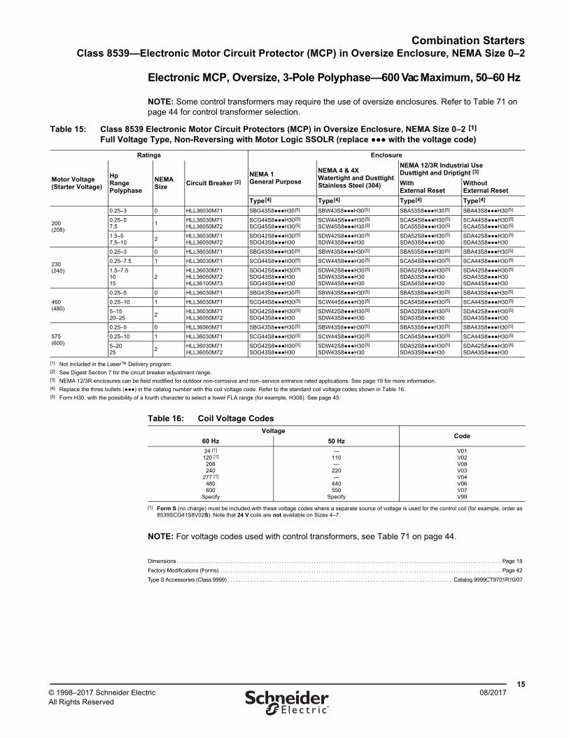
Electronic MCP, Oversize, 3-Pole Polyphase—600 Vac Maximum, 50–60 Hz
NOTE: Some control transformers may require the use of oversize enclosures. Refer to Table 71 on page 44 for control transformer selection.
NOTE: For voltage codes used with control transformers, see Table 71 on page 44.
Dimensions. . . . . . . . . . . . . . . . . . . . . . . . . . . . . . . . . . . . . . . . . . . . . . . . . . . . . . . . . . . . . . . . . . . . . . . . . . . . . . . . . . . . . . . . . . . . . . . . . . . . . . . . . . . . . . . . . . . . . . . . . . . . . . . . . . . . .Page 18
Factory Modifications (Forms) . . . . . . . . . . . . . . . . . . . . . . . . . . . . . . . . . . . . . . . . . . . . . . . . . . . . . . . . . . . . . . . . . . . . . . . . . . . . . . . . . . . . . . . . . . . . . . . . . . . . . . . . . . . . . . . . . . .Page 42
Type S Accessories (Class 9999) . . . . . . . . . . . . . . . . . . . . . . . . . . . . . . . . . . . . . . . . . . . . . . . . . . . . . . . . . . . . . . . . . . . . . . . . . . . . . .Catalog 9999CT9701R10/07
Table 15: Class 8539 Electronic Motor Circuit Protectors (MCP) in Oversize Enclosure, NEMA Size 0–2 [1] Full Voltage Type, Non-Reversing with Motor Logic SSOLR (replace ●●● with the voltage code)
Ratings Enclosure
Motor Voltage(Starter Voltage)
HpRangePolyphase
NEMASize
Circuit Breaker [2]NEMA 1General Purpose
NEMA 4 & 4XWatertight and DusttightStainless Steel (304)
NEMA 12/3R Industrial UseDusttight and Driptight [3]
WithExternal Reset
WithoutExternal Reset
Type[4] Type[4] Type[4] Type[4]
200(208)
0.25–3 0 HLL36030M71 SBG43S8●●●H30[5] SBW43S8●●●H30[5] SBA53S8●●●H30[5] SBA43S8●●●H30[5]
0.25–57.5
1HLL36030M71HLL36050M72
SCG44S8●●●H30[5] SCG45S8●●●H30[5]
SCW44S8●●●H30[5] SCW45S8●●●H30[5]
SCA54S8●●●H30[5] SCA55S8●●●H30[5]
SCA44S8●●●H30[5] SCA45S8●●●H30[5]
1.5–57.5–10
2HLL36030M71HLL36050M72
SDG42S8●●●H30[5] SDG43S8●●●H30
SDW42S8●●●H30[5] SDW43S8●●●H30
SDA52S8●●●H30[5] SDA53S8●●●H30
SDA42S8●●●H30[5] SDA43S8●●●H30
230(240)
0.25–3 0 HLL36030M71 SBG43S8●●●H30[5] SBW43S8●●●H30[5] SBA53S8●●●H30[5] SBA43S8●●●H30[5]
0.25–7.5 1 HLL36030M71 SCG44S8●●●H30[5] SCW44S8●●●H30[5] SCA54S8●●●H30[5] SCA44S8●●●H30[5]
1.5–7.51015
2HLL36030M71HLL36050M72HLL36100M73
SDG42S8●●●H30[5] SDG43S8●●●H30 SDG44S8●●●H30
SDW42S8●●●H30[5] SDW43S8●●●H30 SDW44S8●●●H30
SDA52S8●●●H30[5] SDA53S8●●●H30 SDA54S8●●●H30
SDA42S8●●●H30[5] SDA43S8●●●H30 SDA44S8●●●H30
460(480)
0.25–5 0 HLL36030M71 SBG43S8●●●H30[5] SBW43S8●●●H30[5] SBA53S8●●●H30[5] SBA43S8●●●H30[5]
0.25–10 1 HLL36030M71 SCG44S8●●●H30[5] SCW44S8●●●H30[5] SCA54S8●●●H30[5] SCA44S8●●●H30[5]
5–1520–25
2HLL36030M71HLL36050M72
SDG42S8●●●H30[5] SDG43S8●●●H30
SDW42S8●●●H30[5] SDW43S8●●●H30
SDA52S8●●●H30[5] SDA53S8●●●H30
SDA42S8●●●H30[5] SDA43S8●●●H30
575(600)
0.25–5 0 HLL36060M71 SBG43S8●●●H30[5] SBW43S8●●●H30[5] SBA53S8●●●H30[5] SBA43S8●●●H30[5]
0.25–10 1 HLL36030M71 SCG44S8●●●H30[5] SCW44S8●●●H30[5] SCA54S8●●●H30[5] SCA44S8●●●H30[5]
5–2025
2HLL36030M71HLL36050M72
SDG42S8●●●H30[5] SDG43S8●●●H30
SDW42S8●●●H30[5] SDW43S8●●●H30
SDA52S8●●●H30[5] SDA53S8●●●H30
SDA42S8●●●H30[5] SDA43S8●●●H30
[1] Not included in the Laser™ Delivery program.[2] See Digest Section 7 for the circuit breaker adjustment range.[3] NEMA 12/3R enclosures can be field modified for outdoor non-corrosive and non–service entrance rated applications. See page 19 for more information.[4] Replace the three bullets (●●●) in the catalog number with the coil voltage code. Refer to the standard coil voltage codes shown in Table 16.[5] Form H30, with the possibility of a fourth character to select a lower FLA range (for example, H308). See page 45.
Table 16: Coil Voltage Codes
VoltageCode
60 Hz 50 Hz
24 [1]
120 [1]
208240
277 [1]
480600
Specify
[1] Form S (no charge) must be included with these voltage codes where a separate source of voltage is used for the control coil (for example, order as 8539SCG41S8V02S). Note that 24 V coils are not available on Sizes 4–7.
—110—
220—
440550
Specify
V01V02V08V03V04V06V07V99
Combination StartersClass 8539—Thermal-Magnetic Circuit Breaker
1608/2017 © 1998–2017 Schneider Electric
All Rights Reserved™
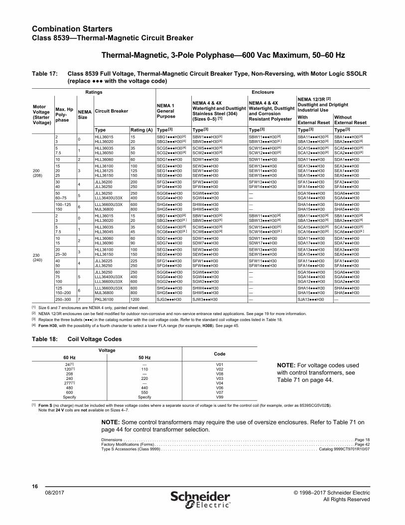
Thermal-Magnetic, 3-Pole Polyphase—600 Vac Maximum, 50–60 Hz
NOTE: Some control transformers may require the use of oversize enclosures. Refer to Table 71 on page 44 for control transformer selection.
Dimensions . . . . . . . . . . . . . . . . . . . . . . . . . . . . . . . . . . . . . . . . . . . . . . . . . . . . . . . . . . . . . . . . . . . . . . . . . . . . . . . . . . . . . . . . . . . . . . . . . . . . . . . . .Page 18Factory Modifications (Forms) . . . . . . . . . . . . . . . . . . . . . . . . . . . . . . . . . . . . . . . . . . . . . . . . . . . . . . . . . . . . . . . . . . . . . . . . . . . . . . . . . . . . . . . . . . .Page 42Type S Accessories (Class 9999) . . . . . . . . . . . . . . . . . . . . . . . . . . . . . . . . . . . . . . . . . . . . . . . . . . . . . . . . . . . . . . . . . . . . . . . Catalog 9999CT9701R10/07
Table 17: Class 8539 Full Voltage, Thermal-Magnetic Circuit Breaker Type, Non-Reversing, with Motor Logic SSOLR (replace ●●● with the voltage code)
Ratings Enclosure
MotorVoltage(StarterVoltage)
Max. HpPoly-phase
NEMASize
Circuit BreakerNEMA 1General Purpose
NEMA 4 & 4XWatertight and Dusttight Stainless Steel (304)(Sizes 0–5) [1]
NEMA 4 & 4XWatertight, Dusttight and Corrosion Resistant Polyester
NEMA 12/3R [2]
Dusttight and DriptightIndustrial Use
WithExternal Reset
WithoutExternal Reset
Type Rating (A) Type[3] Type[3] Type[3] Type[3] Type[3]
200(208)
23
0HLL36015HLL36020
1520
SBG1●●●H30[4]
SBG3●●●H30[4] SBW1●●●H30[4]
SBW3●●●H30[4] SBW11●●●H30[4]
SBW13●●●H30[4 ]SBA11●●●H30[4]
SBA13●●●H30[4] SBA1●●●H30[4]
SBA3●●●H30[4]
57.5
1HLL36035HLL36050
3550
SCG5●●●H30[4]
SCG2●●●H30[4] SCW5●●●H30[4]
SCW2●●●H30[4] SCW15●●●H30[4]
SCW12●●●H30[4] SCA15●●●H30[4]
SCA12●●●H30[4] SCA5●●●H30[4]
SCA2●●●H30[4]
10 2 HLL36060 60 SDG1●●●H30 SDW1●●●H30 SDW11●●●H30 SDA11●●●H30 SDA1●●●H30
152025
3HLL36100HLL36125HLL36150
100125150
SEG3●●●H30 SEG1●●●H30 SEG5●●●H30
SEW3●●●H30 SEW1●●●H30 SEW5●●●H30
SEW13●●●H30 SEW11●●●H30 SEW15●●●H30
SEA13●●●H30 SEA11●●●H30 SEA15●●●H30
SEA3●●●H30 SEA1●●●H30 SEA5●●●H30
3040
4JLL36200JLL36250
200250
SFG3●●●H30 SFG4●●●H30
SFW3●●●H30 SFW4●●●H30
SFW13●●●H30 SFW14●●●H30
SFA13●●●H30 SFA14●●●H30
SFA3●●●H30 SFA4●●●H30
5060–75
5JLL36250LLL36400U33X
250400
SGG6●●●H30SGG4●●●H30
SGW6●●●H30 SGW4●●●H30
——
SGA16●●●H30 SGA14●●●H30
SGA6●●●H30 SGA4●●●H30
100–125150
6LLL36600U33XMJL36800
600800
SHG4●●●H30 SHG5●●●H30
SHW4●●●H30SHW5●●●H30
——
SHA14●●●H30 SHA15●●●H30
SHA4●●●H30 SHA5●●●H30
230(240)
23
0HLL36015HLL36020
1520
SBG1●●●H30[4]
SBG3●●●H30[4 ]SBW1●●●H30[4]
SBW3●●●H30[4] SBW11●●●H30[4]
SBW13●●●H30[4] SBA11●●●H30[4]
SBA13●●●H30[4]SBA1●●●H30[4]
SBA3●●●H30[4]
57.5
1HLL36035HLL36045
3545
SCG5●●●H30[4]
SCG6●●●H30[4 ]SCW5●●●H30[4]
SCW6●●●H30[4] SCW15●●●H30[4]
SCW16●●●H30[4 ]SCA15●●●H30[4]
SCA16●●●H30[4] SCA1●●●H30[4]
SCA6●●●H30[4 ]
1015
2HLL36060HLL36090
6090
SDG1●●●H30SDG7●●●H30
SDW1●●●H30SDW7●●●H30
SDW11●●●H30SDW17●●●H30
SDA11●●●H30SDA17●●●H30
SDA1●●●H30SDA7●●●H30
2025–30
3HLL36100HLL36150
100150
SEG3●●●H30 SEG5●●●H30
SEW3●●●H30 SEW5●●●H30
SEW13●●●H30 SEW15●●●H30
SEA13●●●H30 SEA15●●●H30
SEA3●●●H30 SEA5●●●H30
4050
4JLL36225JLL36250
225250
SFG1●●●H30 SFG4●●●H30
SFW1●●●H30 SFW4●●●H30
SFW11●●●H30 SFW14●●●H30
SFA11●●●H30 SFA14●●●H30
SFA1●●●H30 SFA4●●●H30
6075100
5JLL36250LLL36400U33XLLL36600U33X
250400600
SGG6●●●H30 SGG4●●●H30 SGG2●●●H30
SGW6●●●H30 SGW4●●●H30 SGW2●●●H30
———
SGA16●●●H30 SGA14●●●H30 SGA12●●●H30
SGA6●●●H30 SGA4●●●H30 SGA2●●●H30
125150–200
6LLL36600U33XMJL36800
600800
SHG4●●●H30 SHG5●●●H30
SHW4●●●H30 SHW5●●●H30
——
SHA14●●●H30 SHA15●●●H30
SHA4●●●H30 SHA5●●●H30
250–300 7 PKL36100 1200 SJG3●●●H30 SJW3●●●H30 — SJA13●●●H30 —
[1] Size 6 and 7 enclosures are NEMA 4 only, painted sheet steel.[2] NEMA 12/3R enclosures can be field modified for outdoor non-corrosive and non–service entrance rated applications. See page 19 for more information.[3] Replace the three bullets (●●●) in the catalog number with the coil voltage code. Refer to the standard coil voltage codes listed in Table 18.[4] Form H30, with the possibility of a fourth character to select a lower FLA range (for example, H308). See page 45.
Table 18: Coil Voltage Codes
VoltageCode
60 Hz 50 Hz
24[1]
120[1] 208240
277[1] 480600
Specify
—110—
220—
440550
Specify
V01V02V08V03V04V06V07V99
NOTE: For voltage codes used with control transformers, see Table 71 on page 44.
[1] Form S (no charge) must be included with these voltage codes where a separate source of voltage is used for the control coil (for example, order as 8539SCG5V02S). Note that 24 V coils are not available on Sizes 4–7.
Combination StartersClass 8539—Thermal-Magnetic Circuit Breaker
1708/2017© 1998–2017 Schneider Electric
All Rights Reserved™
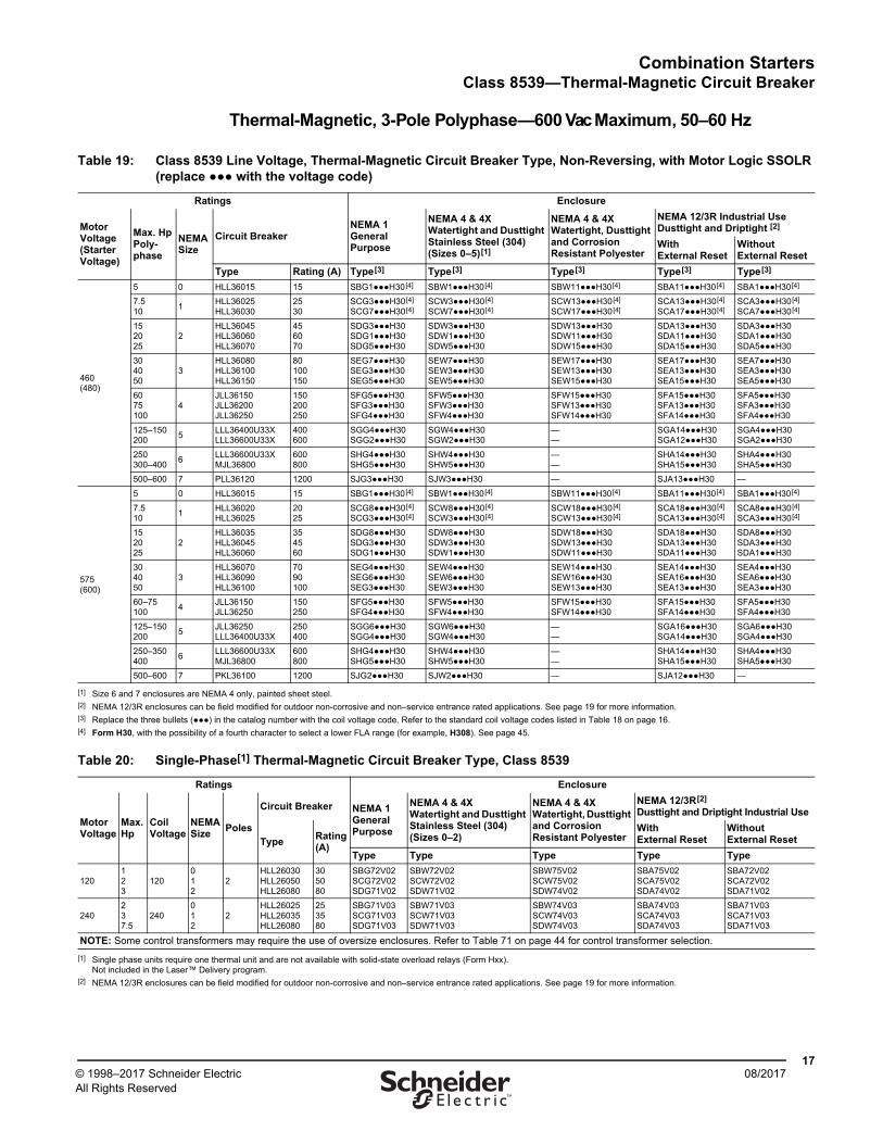
Thermal-Magnetic, 3-Pole Polyphase—600 Vac Maximum, 50–60 Hz
Table 19: Class 8539 Line Voltage, Thermal-Magnetic Circuit Breaker Type, Non-Reversing, with Motor Logic SSOLR (replace ●●● with the voltage code)
Ratings Enclosure
Motor Voltage (Starter Voltage)
Max. HpPoly-phase
NEMASize
Circuit BreakerNEMA 1General Purpose
NEMA 4 & 4XWatertight and Dusttight Stainless Steel (304)(Sizes 0–5)[1]
NEMA 4 & 4XWatertight, Dusttight and Corrosion Resistant Polyester
NEMA 12/3R Industrial Use Dusttight and Driptight [2]
WithExternal Reset
WithoutExternal Reset
Type Rating (A) Type[3] Type[3] Type[3] Type[3] Type[3]
460(480)
5 0 HLL36015 15 SBG1●●●H30[4] SBW1●●●H30[4] SBW11●●●H30[4] SBA11●●●H30[4] SBA1●●●H30[4]
7.510
1HLL36025HLL36030
2530
SCG3●●●H30[4] SCG7●●●H30[4]
SCW3●●●H30[4] SCW7●●●H30[4]
SCW13●●●H30[4] SCW17●●●H30[4]
SCA13●●●H30[4] SCA17●●●H30[4]
SCA3●●●H30[4] SCA7●●●H30[4]
152025
2HLL36045HLL36060HLL36070
456070
SDG3●●●H30 SDG1●●●H30 SDG5●●●H30
SDW3●●●H30 SDW1●●●H30 SDW5●●●H30
SDW13●●●H30 SDW11●●●H30 SDW15●●●H30
SDA13●●●H30 SDA11●●●H30 SDA15●●●H30
SDA3●●●H30 SDA1●●●H30 SDA5●●●H30
304050
3HLL36080HLL36100HLL36150
80100150
SEG7●●●H30 SEG3●●●H30 SEG5●●●H30
SEW7●●●H30 SEW3●●●H30 SEW5●●●H30
SEW17●●●H30 SEW13●●●H30 SEW15●●●H30
SEA17●●●H30 SEA13●●●H30 SEA15●●●H30
SEA7●●●H30 SEA3●●●H30SEA5●●●H30
6075100
4JLL36150JLL36200JLL36250
150200250
SFG5●●●H30 SFG3●●●H30 SFG4●●●H30
SFW5●●●H30 SFW3●●●H30 SFW4●●●H30
SFW15●●●H30 SFW13●●●H30 SFW14●●●H30
SFA15●●●H30 SFA13●●●H30SFA14●●●H30
SFA5●●●H30 SFA3●●●H30 SFA4●●●H30
125–150200
5LLL36400U33XLLL36600U33X
400600
SGG4●●●H30 SGG2●●●H30
SGW4●●●H30 SGW2●●●H30
——
SGA14●●●H30 SGA12●●●H30
SGA4●●●H30 SGA2●●●H30
250300–400
6LLL36600U33XMJL36800
600800
SHG4●●●H30 SHG5●●●H30
SHW4●●●H30 SHW5●●●H30
——
SHA14●●●H30 SHA15●●●H30
SHA4●●●H30SHA5●●●H30
500–600 7 PLL36120 1200 SJG3●●●H30 SJW3●●●H30 — SJA13●●●H30 —
575(600)
5 0 HLL36015 15 SBG1●●●H30[4] SBW1●●●H30[4] SBW11●●●H30[4] SBA11●●●H30[4] SBA1●●●H30[4]
7.510
1HLL36020HLL36025
2025
SCG8●●●H30[4] SCG3●●●H30[4]
SCW8●●●H30[4] SCW3●●●H30[4]
SCW18●●●H30[4] SCW13●●●H30[4]
SCA18●●●H30[4] SCA13●●●H30[4]
SCA8●●●H30[4] SCA3●●●H30[4]
152025
2HLL36035HLL36045HLL36060
354560
SDG8●●●H30 SDG3●●●H30 SDG1●●●H30
SDW8●●●H30 SDW3●●●H30 SDW1●●●H30
SDW18●●●H30 SDW13●●●H30 SDW11●●●H30
SDA18●●●H30 SDA13●●●H30 SDA11●●●H30
SDA8●●●H30 SDA3●●●H30 SDA1●●●H30
304050
3HLL36070HLL36090HLL36100
7090100
SEG4●●●H30 SEG6●●●H30 SEG3●●●H30
SEW4●●●H30 SEW6●●●H30 SEW3●●●H30
SEW14●●●H30SEW16●●●H30SEW13●●●H30
SEA14●●●H30SEA16●●●H30 SEA13●●●H30
SEA4●●●H30 SEA6●●●H30SEA3●●●H30
60–75100
4JLL36150JLL36250
150250
SFG5●●●H30 SFG4●●●H30
SFW5●●●H30SFW4●●●H30
SFW15●●●H30SFW14●●●H30
SFA15●●●H30 SFA14●●●H30
SFA5●●●H30 SFA4●●●H30
125–150200
5JLL36250LLL36400U33X
250400
SGG6●●●H30 SGG4●●●H30
SGW6●●●H30 SGW4●●●H30
——
SGA16●●●H30 SGA14●●●H30
SGA6●●●H30 SGA4●●●H30
250–350400
6LLL36600U33XMJL36800
600800
SHG4●●●H30 SHG5●●●H30
SHW4●●●H30 SHW5●●●H30
——
SHA14●●●H30 SHA15●●●H30
SHA4●●●H30 SHA5●●●H30
500–600 7 PKL36100 1200 SJG2●●●H30 SJW2●●●H30 — SJA12●●●H30 —
[1] Size 6 and 7 enclosures are NEMA 4 only, painted sheet steel.[2] NEMA 12/3R enclosures can be field modified for outdoor non-corrosive and non–service entrance rated applications. See page 19 for more information.[3] Replace the three bullets (●●●) in the catalog number with the coil voltage code. Refer to the standard coil voltage codes listed in Table 18 on page 16.[4] Form H30, with the possibility of a fourth character to select a lower FLA range (for example, H308). See page 45.
Table 20: Single-Phase[1] Thermal-Magnetic Circuit Breaker Type, Class 8539
Ratings Enclosure
MotorVoltage
Max.Hp
CoilVoltage
NEMASize
Poles
Circuit Breaker NEMA 1General Purpose
NEMA 4 & 4XWatertight and Dusttight Stainless Steel (304)(Sizes 0–2)
NEMA 4 & 4XWatertight, Dusttight and Corrosion Resistant Polyester
NEMA 12/3R[2] Dusttight and Driptight Industrial Use
TypeRating (A)
WithExternal Reset
WithoutExternal Reset
Type Type Type Type Type
120123
120012
2HLL26030HLL26050HLL26080
305080
SBG72V02SCG72V02SDG71V02
SBW72V02SCW72V02SDW71V02
SBW75V02SCW75V02SDW74V02
SBA75V02SCA75V02SDA74V02
SBA72V02SCA72V02SDA71V02
240237.5
240012
2HLL26025HLL26035HLL26080
253580
SBG71V03SCG71V03SDG71V03
SBW71V03SCW71V03SDW71V03
SBW74V03SCW74V03SDW74V03
SBA74V03SCA74V03SDA74V03
SBA71V03SCA71V03SDA71V03
NOTE: Some control transformers may require the use of oversize enclosures. Refer to Table 71 on page 44 for control transformer selection.
[1] Single phase units require one thermal unit and are not available with solid-state overload relays (Form Hxx).Not included in the Laser™ Delivery program.
[2] NEMA 12/3R enclosures can be field modified for outdoor non-corrosive and non–service entrance rated applications. See page 19 for more information.

Combination StartersClass 8538, 8539—Approximate Dimensions, Shipping Weights
1808/2017 © 1998–2017 Schneider Electric
All Rights Reserved™
Dimensions for Non-Reversing Combination Starters
NEMA 1 Enclosures
NOTE: The dimensions in Tables 21 and 22 include space for Form FF4T (standard control transformer). An oversize enclosure may be required for Form FF4T11 (100 VA additional capacity) and Form FF4T12 (200 VA additional capacity). See Table 57 on page 38 for replacement transformer selection.
Table 21: Sizes 0–2, NEMA 1 Enclosure—See Figure 1
NEMA Size
Class TypeDimensions, in. Top & Bottom Sides Wt.
(lb)A B C D E F G H I J K L M N O P W X Y
0–18538 SBG, SCG 9.5 22.5 8.34 6.38 20.5 14.66 1.81 1.69 3 2.31 1.06 3.25 2.19 1.25 0.88 — 0.5–0.75 0.5–0.75 0.5 38
8539 SBG, SCG 9.5 22.5 9.84 6.38 20.5 14.66 1.81 1.69 3 2.31 1.06 3.25 2.19 1.25 0.88 — 0.5–0.75 0.5–0.75 0.5 38
2 8538, 8539 SDG 10.5 26 9.59 7.38 24 16.91 2.13 2 4 2.31 1.06 3.25 2.19 1.25 0.88 — 1–1.25 0.5–0.75 0.5 54
Table 22: Sizes 3–6, NEMA 1 Enclosure—See Figure 2
NEMASize
Type ClassDimensions, in. Top & Bottom Sides Wt.
(lb)A B C D E F G H I J K L M N O P W X Y
3[1] 8538, 8539
SEG 15.25 42 10.59 9.25 3 22.72 41 0.5 — 2.83 3.53 5 2.69 5.38 1.28 0.911–1.252–2.5
0.5–0.75 0.5 102
48538 SFG 16 52.5 10.53 10 3 23.66 51.5 0.5 — 2.83 3.53 5 2.69 5.38 1.28 0.91 2.5 0.5–0.75 0.5 163
8539 SFG 16 52.5 10.53 10 3 23.66 51.5 0.5 — 2.83 3.53 5 2.69 5.38 1.28 0.91 2.5 0.5–0.75 0.5 163
58538 SGG 20 78 15.5 12 4 29.41 77 0.5 — 3.52 4.61 9.25 3.19 — — —
0.5–0.75[2]
3 — 450
8539 SGG 20 66 13.72 12 4 29.41 65 0.5 — 3.52 4.61 5 3.19 — — — 0.5–0.75 3 — 420
6[3] 8538, 8539
SHG 36 90 21.03 — — 41.38 — — — — — 5 — — — — — — — —
[1] For Class 8538 Size 3 devices with 200 A fuse clips, use the dimensions for Class 8538 Size 4 devices.[2] Left side only.[3] Size 6 enclosures are floor mounting.
Figure 1: NEMA 1 EnclosureSizes 0–2
Figure 2: NEMA 1 EnclosureSizes 3–6
YO
NC
HandleSwing
E B
KMD
A
Y
(4) 0.31 Dia. Mtg. Holes8
F
W X W
GJ
HI
Cover Open 90°
L DA
E HL
HandleSwing
C
P
O
Y
BG
Y
J
NM
K
W X W
F
Dia. Mtg. Holes (Size 3–4)
Dia. Mtg. Holes (Size 5)
0.4411
0.5614
(4)
(4)
Cover Open 90°
Combination StartersClass 8538, 8539—Approximate Dimensions, Shipping Weights
1908/2017© 1998–2017 Schneider Electric
All Rights Reserved™
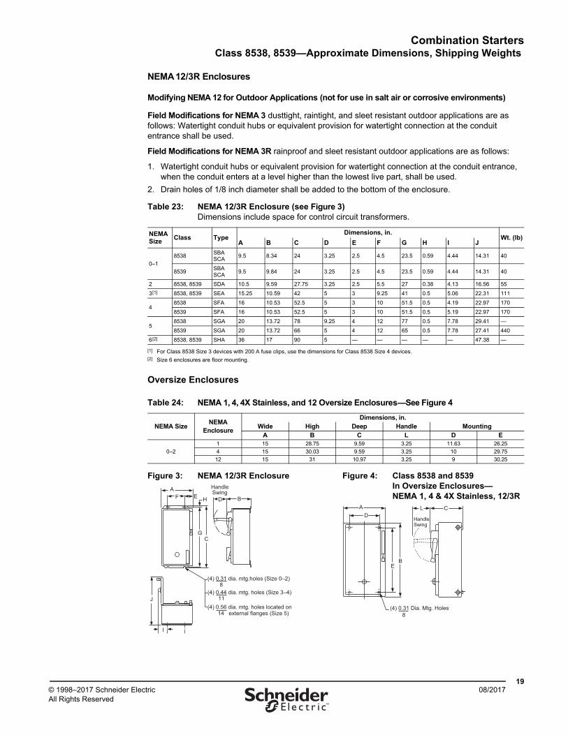
NEMA 12/3R Enclosures
Modifying NEMA 12 for Outdoor Applications (not for use in salt air or corrosive environments)
Field Modifications for NEMA 3 dusttight, raintight, and sleet resistant outdoor applications are as follows: Watertight conduit hubs or equivalent provision for watertight connection at the conduit entrance shall be used.
Field Modifications for NEMA 3R rainproof and sleet resistant outdoor applications are as follows:
1. Watertight conduit hubs or equivalent provision for watertight connection at the conduit entrance, when the conduit enters at a level higher than the lowest live part, shall be used.
2. Drain holes of 1/8 inch diameter shall be added to the bottom of the enclosure.
Oversize Enclosures
Table 23: NEMA 12/3R Enclosure (see Figure 3)Dimensions include space for control circuit transformers.
NEMASize
Class TypeDimensions, in.
Wt. (lb)A B C D E F G H I J
0–1
8538SBASCA
9.5 8.34 24 3.25 2.5 4.5 23.5 0.59 4.44 14.31 40
8539SBASCA
9.5 9.84 24 3.25 2.5 4.5 23.5 0.59 4.44 14.31 40
2 8538, 8539 SDA 10.5 9.59 27.75 3.25 2.5 5.5 27 0.38 4.13 16.56 55
3[1]
[1] For Class 8538 Size 3 devices with 200 A fuse clips, use the dimensions for Class 8538 Size 4 devices.
8538, 8539 SEA 15.25 10.59 42 5 3 9.25 41 0.5 5.06 22.31 111
48538 SFA 16 10.53 52.5 5 3 10 51.5 0.5 4.19 22.97 170
8539 SFA 16 10.53 52.5 5 3 10 51.5 0.5 5.19 22.97 170
58538 SGA 20 13.72 78 9.25 4 12 77 0.5 7.78 29.41 —
8539 SGA 20 13.72 66 5 4 12 65 0.5 7.78 27.41 440
6[2]
[2] Size 6 enclosures are floor mounting.
8538, 8539 SHA 36 17 90 5 — — — — — 47.38 —
Table 24: NEMA 1, 4, 4X Stainless, and 12 Oversize Enclosures—See Figure 4
NEMA SizeNEMA
Enclosure
Dimensions, in.Wide High Deep Handle Mounting
A B C L D E
0–2
1 15 28.75 9.59 3.25 11.63 26.25
4 15 30.03 9.59 3.25 10 29.75
12 15 31 10.97 3.25 9 30.25
Figure 3: NEMA 12/3R Enclosure Figure 4: Class 8538 and 8539 In Oversize Enclosures—NEMA 1, 4 & 4X Stainless, 12/3R B
HandleSwing
C
FA
(4) 0.31 dia. mtg.holes (Size 0–2)8
(4) 0.44 dia. mtg. holes (Size 3–4)11
(4) 0.56 dia. mtg. holes located on14 external flanges (Size 5)
J
I
DE
G
HC
HandleSwing
EB
DA
(4) 0.31 Dia. Mtg. Holes 8
L
Combination StartersClass 8538, 8539—Approximate Dimensions, Shipping Weights
2008/2017 © 1998–2017 Schneider Electric
All Rights Reserved™
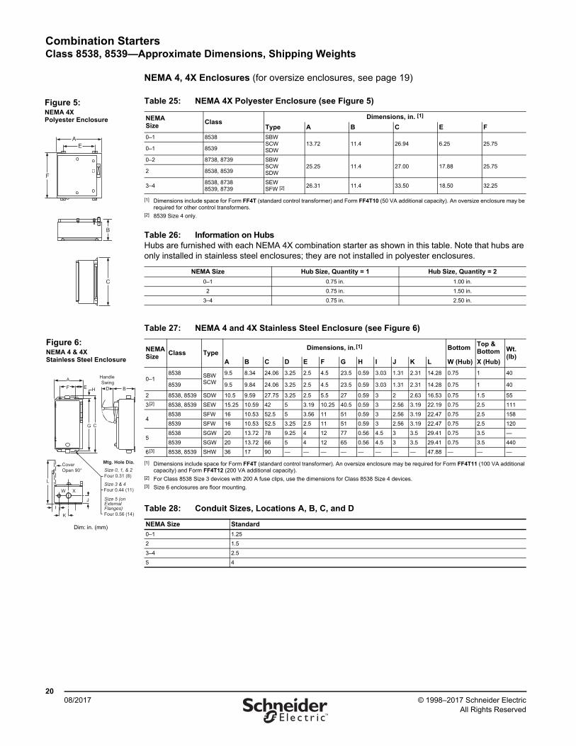
NEMA 4, 4X Enclosures (for oversize enclosures, see page 19)
Table 25: NEMA 4X Polyester Enclosure (see Figure 5)
NEMASize
ClassDimensions, in. [1]
[1] Dimensions include space for Form FF4T (standard control transformer) and Form FF4T10 (50 VA additional capacity). An oversize enclosure may be required for other control transformers.
Type A B C E F
0–1 8538 SBW SCW SDW
13.72 11.4 26.94 6.25 25.750–1 8539
0–2 8738, 8739 SBW SCWSDW
25.25 11.4 27.00 17.88 25.752 8538, 8539
3–48538, 87388539, 8739
SEWSFW [2]
[2] 8539 Size 4 only.
26.31 11.4 33.50 18.50 32.25
Table 26: Information on HubsHubs are furnished with each NEMA 4X combination starter as shown in this table. Note that hubs are only installed in stainless steel enclosures; they are not installed in polyester enclosures.
NEMA Size Hub Size, Quantity = 1 Hub Size, Quantity = 2
0–1 0.75 in. 1.00 in.
2 0.75 in. 1.50 in.
3–4 0.75 in. 2.50 in.
Table 27: NEMA 4 and 4X Stainless Steel Enclosure (see Figure 6)
NEMASize
Class TypeDimensions, in.[1]
[1] Dimensions include space for Form FF4T (standard control transformer). An oversize enclosure may be required for Form FF4T11 (100 VA additional capacity) and Form FF4T12 (200 VA additional capacity).
BottomTop & Bottom Wt.
(lb)A B C D E F G H I J K L W (Hub) X (Hub)
0–18538 SBW
SCW
9.5 8.34 24.06 3.25 2.5 4.5 23.5 0.59 3.03 1.31 2.31 14.28 0.75 1 40
8539 9.5 9.84 24.06 3.25 2.5 4.5 23.5 0.59 3.03 1.31 2.31 14.28 0.75 1 40
2 8538, 8539 SDW 10.5 9.59 27.75 3.25 2.5 5.5 27 0.59 3 2 2.63 16.53 0.75 1.5 55
3[2]
[2] For Class 8538 Size 3 devices with 200 A fuse clips, use the dimensions for Class 8538 Size 4 devices.
8538, 8539 SEW 15.25 10.59 42 5 3.19 10.25 40.5 0.59 3 2.56 3.19 22.19 0.75 2.5 111
48538 SFW 16 10.53 52.5 5 3.56 11 51 0.59 3 2.56 3.19 22.47 0.75 2.5 158
8539 SFW 16 10.53 52.5 3.25 2.5 11 51 0.59 3 2.56 3.19 22.47 0.75 2.5 120
58538 SGW 20 13.72 78 9.25 4 12 77 0.56 4.5 3 3.5 29.41 0.75 3.5 —
8539 SGW 20 13.72 66 5 4 12 65 0.56 4.5 3 3.5 29.41 0.75 3.5 440
6[3]
[3] Size 6 enclosures are floor mounting.
8538, 8539 SHW 36 17 90 — — — — — — — — 47.88 — — —
Table 28: Conduit Sizes, Locations A, B, C, and D
NEMA Size Standard
0–1 1.25
2 1.5
3–4 2.5
5 4
AE
F
C
B
Figure 5:NEMA 4X Polyester Enclosure
B
Handle Swing
C
F
A
Four 0.31 (8)
Mtg. Hole Dia. Size 0, 1, & 2
Four 0.44 (11)Size 3 & 4
Four 0.56 (14)
Size 5 (on External Flanges)
L
W X
I
Cover Open 90°
DE
K
J
G
H
Figure 6:NEMA 4 & 4X Stainless Steel Enclosure
Dim: in. (mm)
Combination StartersClass 8538, 8539—Panel Layout
2108/2017© 1998–2017 Schneider Electric
All Rights Reserved™
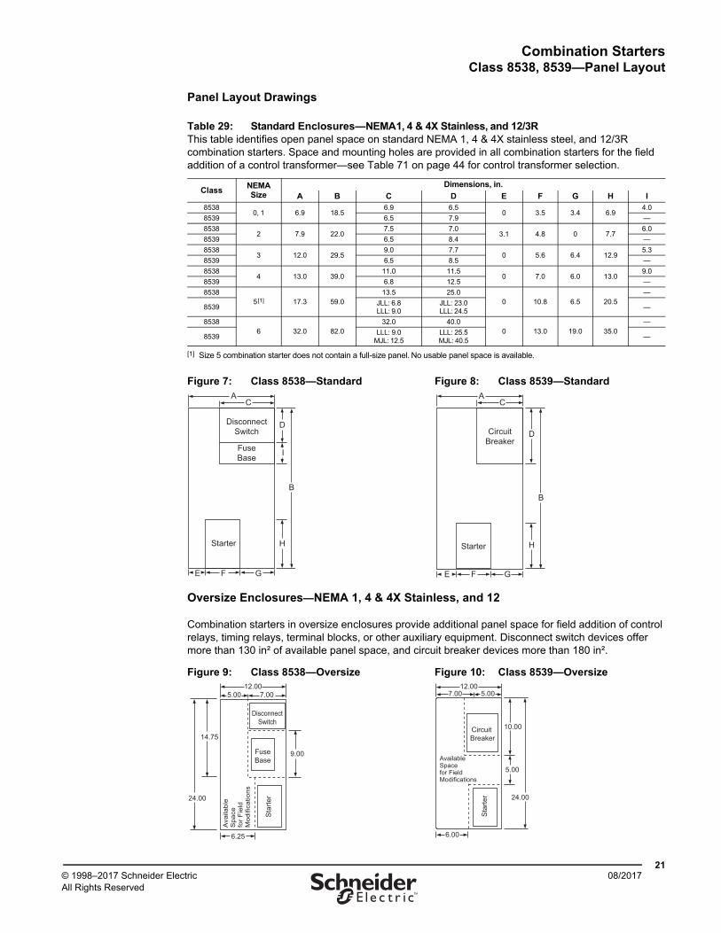
Panel Layout Drawings
Oversize Enclosures—NEMA 1, 4 & 4X Stainless, and 12
Combination starters in oversize enclosures provide additional panel space for field addition of control relays, timing relays, terminal blocks, or other auxiliary equipment. Disconnect switch devices offer more than 130 in² of available panel space, and circuit breaker devices more than 180 in².
Table 29: Standard Enclosures—NEMA1, 4 & 4X Stainless, and 12/3RThis table identifies open panel space on standard NEMA 1, 4 & 4X stainless steel, and 12/3R combination starters. Space and mounting holes are provided in all combination starters for the field addition of a control transformer—see Table 71 on page 44 for control transformer selection.
ClassNEMA Size
Dimensions, in.
A B C D E F G H I8538
0, 1 6.9 18.56.9 6.5
0 3.5 3.4 6.94.0
8539 6.5 7.9 —
85382 7.9 22.0
7.5 7.03.1 4.8 0 7.7
6.0
8539 6.5 8.4 —
85383 12.0 29.5
9.0 7.70 5.6 6.4 12.9
5.3
8539 6.5 8.5 —
85384 13.0 39.0
11.0 11.50 7.0 6.0 13.0
9.0
8539 6.8 12.5 —
85385[1]
[1] Size 5 combination starter does not contain a full-size panel. No usable panel space is available.
17.3 59.013.5 25.0
0 10.8 6.5 20.5—
8539JLL: 6.8LLL: 9.0
JLL: 23.0LLL: 24.5
—
85386 32.0 82.0
32.0 40.00 13.0 19.0 35.0
—
8539LLL: 9.0
MJL: 12.5LLL: 25.5MJL: 40.5
—
Figure 7: Class 8538—Standard Figure 8: Class 8539—Standard
Figure 9: Class 8538—Oversize Figure 10: Class 8539—Oversize
C
DisconnectSwitch
FuseBase
Starter
GFE
A
H
D
B
I
C
GF
Starter
CircuitBreaker
E
A
H
D
B
7.005.0012.00
6.25
9.00
14.75
DisconnectSwitch
FuseBase
Sta
rter
Ava
ilabl
e S
pace
fo
r F
ield
M
odifi
catio
ns
24.00
7.0012.00
5.00
6.00
10.00
5.00
Circuit Breaker
Sta
rter
Available Space for Field Modifications
24.00
Combination StartersClass 8738, 8739—Reversing—Overload Protection
2208/2017 © 1998–2017 Schneider Electric
All Rights Reserved™
Reversing Combination Starters, NEMA Style
General Information—Reversing Combination Starters
Class 8738 and 8739 Type S reversing combination starters combine the requirements of motor overload and short-circuit protection into one convenient package. Type S reversing combination starters are manufactured in accordance with NEMA standards, are UL Listed, and are CSA certified. Class 8738 and 8739 reversing combination starters are designed to operate at 600 Vac, 50–60 Hz. Type S reversing combination starters come standard with melting alloy overload relays. Bimetallic and solid-state overload relays are available as options (see pages 45–46).
Enclosures—Class 8738 and 8739 reversing combination starters are available in the following enclosures:
• NEMA 1 General Purpose
• NEMA 4 & 4X Watertight and Dusttight
• NEMA 4X Watertight, Dusttight, and Corrosion Resistant Glass-Polyester
• NEMA 12/3R Dusttight and Driptight for Industrial Use
The NEMA 4 & 4X stainless steel enclosures (Sizes 0–5) have a brushed finish. Sizes 6–7 are sheet-steel enclosures and are rated NEMA 4 only.
The NEMA 4X glass-polyester enclosed devices are UL Listed. Hubs are furnished as standard on NEMA 4X enclosures.
NEMA 12/3R enclosures can be field modified for outdoor applications. Specify Form G26 for NEMA 3R (no additional charge). See page 19 for details.
Coil Voltages—AC coils are available for application at 50/60 Hz. NEMA Sizes 00–5 are furnished with coils designed to operate satisfactorily on line voltages of 85–110% of rated voltage. NEMA Size 6–7 contactors are furnished with a DC coil operated by a solid-state rectifier circuit, which is powered by an AC source.
NOTE: A voltage code is required when ordering combination starters. Polyphase combination starters with 24 Vac or 120 Vac coil voltages come wired for separate control.
Auxiliary Contacts—Additional auxiliary contacts may be added to Type S starters. See page 37 for the maximum number of auxiliary units and the Form designations for factory installed auxiliary contacts. See catalog 9999CT9701 for auxiliary contact kits for field installation.
Type S Accessories—Additional accessories such as fuse blocks, fuse clip kits, disconnect switch and circuit breaker interlocks, and cover-mounted control units are available for field modifications. For factory modifications (Forms), see page 42. For field modification kits, see catalog 9999CT9701.
Combination StartersClass 8738, 8739—General Information
2308/2017© 1998–2017 Schneider Electric
All Rights Reserved™
Overload Protection
Type S magnetic starters are used for full-voltage starting and stopping of AC squirrel cage motors. Motor overload protection for three-phase starter applications can be provided through one of four options, as follows:
Solid-State Overload Relay Protection (Motor Logic™ SSOLR)—These ambient insensitive overload relays are available on Sizes 00–6 and standard on Size 7. They provide phase loss and phase unbalance protection. To order, add Form H30 (for selectable trip class 10 or 20 protection). For more information about Motor Logic SSOLRs, see page 45 and catalog 9065CT9701. (Product catalog number example: 8536SCO3V06H30)
Adapted Bimetallic Overload Relay (NEMA Sizes 00–1)—The adapted bimetallic motor starter includes a specially designed adapter. It attaches with bus bars to the Type S NEMA contactor and holds the IEC-style bimetallic overload relay (type LRD or LR3D). This starter configuration can be ordered by adding Form E (adapter only) to the standard catalog number. The LRD or LR3D bimetallic overload relay must be purchased separately, based on the motor FLA, and installed in the field in order to operate the starter. For more information—including how to order the adapted bimetallic overload relay as a factory installed option—see page 45 and catalog 9065CT9701. (Product catalog number example: 8536SCO3V06E)
TeSys T Motor Management System (NEMA Sizes 1–6)—The flexible TeSys T system integrates seamlessly into your automation system through five major communication protocols. The TeSys T system can predict what will happen in the process, as it accurately monitors current, voltage, and power over a wide range. This option is available for control voltages of 24 Vac or 100–240 Vac. For additional information about the TeSys T Motor Management System, see page 46 and catalog 9065CT9701. NOTE: The full catalog number contains a four-character Form number (for example, 8536SCO3V06H616).
Melting Alloy Thermal Overload Relays—Melting alloy style thermal overload blocks are installed as part of the starter, and thermal elements must be selected and installed separately in order to operate the starter. For a three-phase motor, three thermal units must be ordered using the tables in catalog 9065CT9701. The catalog number includes no Form number (for example, 8536SCO3V06).
Combination StartersClass 8738—Reversing, Fusible Disconnect Switch Type
2408/2017 © 1998–2017 Schneider Electric
All Rights Reserved™
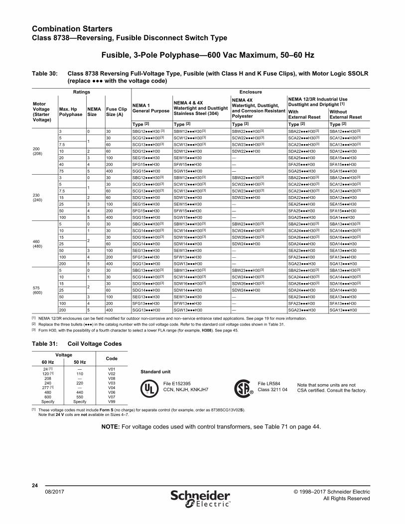
Fusible, 3-Pole Polyphase—600 Vac Maximum, 50–60 Hz
NOTE: For voltage codes used with control transformers, see Table 71 on page 44.
Table 30: Class 8738 Reversing Full-Voltage Type, Fusible (with Class H and K Fuse Clips), with Motor Logic SSOLR (replace ●●● with the voltage code)
Ratings Enclosure
Motor Voltage(Starter Voltage)
Max. HpPolyphase
NEMASize
Fuse ClipSize (A)
NEMA 1General Purpose
NEMA 4 & 4XWatertight and Dusttight Stainless Steel (304)
NEMA 4X Watertight, Dusttight, and Corrosion Resistant Polyester
NEMA 12/3R Industrial Use Dusttight and Driptight [1]
WithExternal Reset
WithoutExternal Reset
Type [2] Type [2] Type [2] Type [2] Type [2]
200(208)
3 0 30 SBG12●●●H30 [3] SBW12●●●H30[3] SBW22●●●H30[3] SBA22●●●H30[3] SBA12●●●H30[3]
51
30 SCG12●●●H30[3] SCW12●●●H30[3] SCW22●●●H30[3] SCA22●●●H30[3] SCA12●●●H30[3]
7.5 60 SCG13●●●H30[3] SCW13●●●H30[3] SCW23●●●H30[3] SCA23●●●H30[3] SCA13●●●H30[3]
10 2 60 SDG12●●●H30 SDW12●●●H30 SDW22●●●H30 SDA22●●●H30 SDA12●●●H30
20 3 100 SEG15●●●H30 SEW15●●●H30 — SEA25●●●H30 SEA15●●●H30
40 4 200 SFG15●●●H30 SFW15●●●H30 — SFA25●●●H30 SFA15●●●H30
75 5 400 SGG15●●●H30 SGW15●●●H30 — SGA25●●●H30 SGA15●●●H30
230(240)
3 0 30 SBG12●●●H30[3] SBW12●●●H30[3] SBW22●●●H30[3] SBA22●●●H30[3] SBA12●●●H30[3]
51
30 SCG12●●●H30[3] SCW12●●●H30[3] SCW22●●●H30[3] SCA22●●●H30[3] SCA12●●●H30[3]
7.5 60 SCG13●●●H30[3] SCW13●●●H30[3] SCW23●●●H30[3] SCA23●●●H30[3] SCA13●●●H30[3]
15 2 60 SDG12●●●H30 SDW12●●●H30 SDW22●●●H30 SDA22●●●H30 SDA12●●●H30
25 3 100 SEG15●●●H30 SEW15●●●H30 — SEA25●●●H30 SEA15●●●H30
50 4 200 SFG15●●●H30 SFW15●●●H30 — SFA25●●●H30 SFA15●●●H30
100 5 400 SGG15●●●H30 SGW15●●●H30 — SGA25●●●H30 SGA1●●●H30
460(480)
5 0 30 SBG13●●●H30[3] SBW13●●●H30[3] SBW23●●●H30[3] SBA23●●●H30[3] SBA13●●●H30[3]
10 1 30 SCG14●●●H30[3] SCW14●●●H30[3] SCW24●●●H30[3] SCA24●●●H30[3] SCA14●●●H30[3]
152
30 SDG16●●●H30[3] SDW16●●●H30[3] SDW26●●●H30[3] SDA26●●●H30[3] SDA16●●●H30[3]
25 60 SDG14●●●H30 SDW14●●●H30 SDW24●●●H30 SDA24●●●H30 SDA14●●●H30
50 3 100 SEG13●●●H30 SEW13●●●H30 — SEA23●●●H30 SEA13●●●H30
100 4 200 SFG13●●●H30 SFW13●●●H30 — SFA23●●●H30 SFA13●●●H30
200 5 400 SGG13●●●H30 SGW13●●●H30 — SGA23●●●H30 SGA13●●●H30
575(600)
5 0 30 SBG13●●●H30[3] SBW13●●●H30[3] SBW23●●●H30[3] SBA23●●●H30[3] SBA13●●●H30[3]
10 1 30 SCG14●●●H30[3] SCW14●●●H30[3] SCW24●●●H30[3] SCA24●●●H30[3] SCA14●●●H30[3]
152
30 SDG16●●●H30[3] SDW16●●●H30[3] SDW26●●●H30[3] SDA26●●●H30[3] SDA16●●●H30[3]
25 60 SDG14●●●H30 SDW14●●●H30 SDW24●●●H30 SDA24●●●H30 SDA14●●●H30
50 3 100 SEG13●●●H30 SEW13●●●H30 — SEA23●●●H30 SEA13●●●H30
100 4 200 SFG13●●●H30 SFW13●●●H30 — SFA23●●●H30 SFA13●●●H30
200 5 400 SGG13●●●H30 SGW13●●●H30 — SGA23●●●H30 SGA13●●●H30
[1] NEMA 12/3R enclosures can be field modified for outdoor non-corrosive and non–service entrance rated applications. See page 19 for more information.[2] Replace the three bullets (●●●) in the catalog number with the coil voltage code. Refer to the standard coil voltage codes shown in Table 31.[3] Form H30, with the possibility of a fourth character to select a lower FLA range (for example, H308). See page 45.
Table 31: Coil Voltage Codes
VoltageCode
60 Hz 50 Hz
24 [1]
120 [1] 208240
277 [1] 480600
Specify
—110—
220—
440550
Specify
V01V02V08V03V04V06V07V99
[1] These voltage codes must include Form S (no charge) for separate control (for example, order as 8738SCG13V02S).Note that 24 V coils are not available on Sizes 4–7.
Standard unit
File E152395CCN, NKJH, KNKJH7
File LR584Class 3211 04
Note that some units are not CSA certified. Consult the factory.
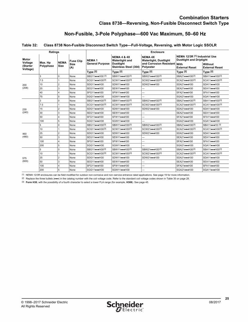
Combination StartersClass 8738—Reversing, Non-Fusible Disconnect Switch Type
2508/2017© 1998–2017 Schneider Electric
All Rights Reserved™
Non-Fusible, 3-Pole Polyphase—600 Vac Maximum, 50–60 Hz
Table 32: Class 8738 Non-Fusible Disconnect Switch Type—Full-Voltage, Reversing, with Motor Logic SSOLR
Ratings Enclosure
Motor Voltage(Starter Voltage)
Max. HpPolyphase
NEMASize
Fuse ClipSize(A)
NEMA 1General Purpose
NEMA 4 & 4XWatertight and Dusttight Stainless Steel (304)
NEMA 4XWatertight, Dusttightand Corrosion ResistantPolyester
NEMA 12/3R [1] Industrial UseDusttight and Driptight
WithExternal Reset
WithoutExternal Reset
Type [2] Type [2] Type [2] Type [2] Type [2]
200(208)
3 0 None SBG11●●●H30 [3] SBW11●●●H30[3] SBW21●●●H30[3] SBA21●●●H30[3] SBA11●●●H30[3]
7.5 1 None SCG11●●●H30[3] SCW11●●●H30[3] SCW21●●●H30[3] SCA21●●●H30[3] SCA11●●●H30[3]
10 2 None SDG11●●●H30 SDW11●●●H30 SDW21●●●H30 SDA21●●●H30 SDA11●●●H30
25 3 None SEG11●●●H30 SEW11●●●H30 — SEA21●●●H30 SEA11●●●H30
40 4 None SFG11●●●H30 SFW11●●●H30 — SFA21●●●H30 SFA11●●●H30
75 5 None SGG11●●●H30 SGW11●●●H30 — SGA21●●●H30 SGA11●●●H30
230(240)
3 0 None SBG11●●●H30[3] SBW11●●●H30[3] SBW21●●●H30[3] SBA21●●●H30[3] SBA11●●●H30[3]
7.5 1 None SCG11●●●H30[3] SCW11●●●H30[3] SCW21●●●H30[3] SCA21●●●H30[3] SCA11●●●H30[3]
15 2 None SDG11●●●H30 SDW11●●●H30 SDW21●●●H30 SDA21●●●H30 SDA11●●●H30
30 3 None SEG11●●●H30 SEW11●●●H30 — SEA21●●●H30 SEA11●●●H30
50 4 None SFG11●●●H30 SFW11●●●H30 — SFA21●●●H30 SFA11●●●H30
100 5 None SGG11●●●H30 SGW11●●●H30 — SGA21●●●H30 SGA11●●●H30
460(480)
5 0 None SBG11●●●H30[3] SBW11●●●H30[3] SBW21●●●H30[3] SBA21●●●H30[3] SBA11●●●H3 [3]
10 1 None SCG11●●●H30[3] SCW11●●●H30[3] SCW21●●●H30[3] SCA21●●●H30[3] SCA11●●●H30[3]
25 2 None SDG11●●●H30 SDW11●●●H30 SDW21●●●H30 SDA21●●●H30 SDA11●●●H30
50 3 None SEG11●●●H30 SEW11●●●H30 — SEA21●●●H30 SEA11●●●H30
100 4 None SFG11●●●H30 SFW11●●●H30 — SFA21●●●H30 SFA11●●●H30
200 5 None SGG11●●●H30 SGW11●●●H30 — SGA21●●●H30 SGA11●●●H30
575(600)
5 0 None SBG11●●●H30[3] SBW11●●●H30[3] SBW21●●●H30[3] SBA21●●●H30[3] SBA11●●●H30[3]
10 1 None SCG11●●●H30[3] SCW11●●●H30[3] SCW21●●●H30[3] SCA21●●●H30[3] SCA11●●●H30[3]
25 2 None SDG11●●●H30 SDW11●●●H30 SDW21●●●H30 SDA21●●●H30 SDA11●●●H30
50 3 None SEG11●●●H30 SEW11●●●H30 — SEA21●●●H30 SEA11●●●H30
100 4 None SFG11●●●H30 SFW11●●●H30 — SFA21●●●H30 SFA11●●●H30
200 5 None SGG11●●●H30 SGW11●●●H30 — SGA21●●●H30 SGA11●●●H30
[1] NEMA 12/3R enclosures can be field modified for outdoor non-corrosive and non–service entrance rated applications. See page 19 for more information.[2] Replace the three bullets (●●●) in the catalog number with the coil voltage code. Refer to the standard coil voltage codes shown in Table 35 on page 28.[3] Form H30, with the possibility of a fourth character to select a lower FLA range (for example, H308). See page 45.
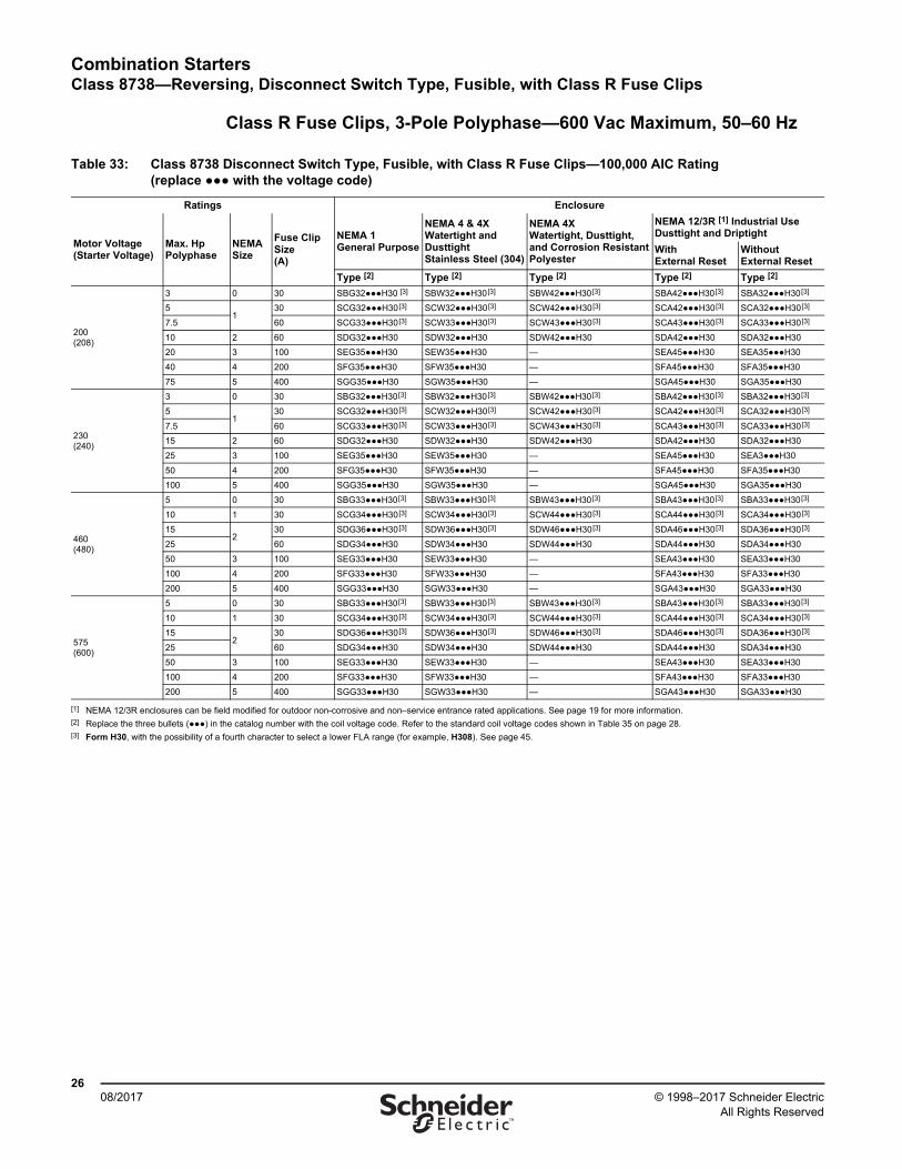
Combination StartersClass 8738—Reversing, Disconnect Switch Type, Fusible, with Class R Fuse Clips
2608/2017 © 1998–2017 Schneider Electric
All Rights Reserved™
Class R Fuse Clips, 3-Pole Polyphase—600 Vac Maximum, 50–60 Hz
Table 33: Class 8738 Disconnect Switch Type, Fusible, with Class R Fuse Clips—100,000 AIC Rating (replace ●●● with the voltage code)
Ratings Enclosure
Motor Voltage(Starter Voltage)
Max. HpPolyphase
NEMASize
Fuse ClipSize(A)
NEMA 1General Purpose
NEMA 4 & 4XWatertight and Dusttight Stainless Steel (304)
NEMA 4XWatertight, Dusttight, and Corrosion ResistantPolyester
NEMA 12/3R [1] Industrial UseDusttight and Driptight
WithExternal Reset
WithoutExternal Reset
Type [2] Type [2] Type [2] Type [2] Type [2]
200(208)
3 0 30 SBG32●●●H30 [3] SBW32●●●H30[3] SBW42●●●H30[3] SBA42●●●H30[3] SBA32●●●H30[3]
51
30 SCG32●●●H30[3] SCW32●●●H30[3] SCW42●●●H30[3] SCA42●●●H30[3] SCA32●●●H30[3]
7.5 60 SCG33●●●H30[3] SCW33●●●H30[3] SCW43●●●H30[3] SCA43●●●H30[3] SCA33●●●H30[3]
10 2 60 SDG32●●●H30 SDW32●●●H30 SDW42●●●H30 SDA42●●●H30 SDA32●●●H30
20 3 100 SEG35●●●H30 SEW35●●●H30 — SEA45●●●H30 SEA35●●●H30
40 4 200 SFG35●●●H30 SFW35●●●H30 — SFA45●●●H30 SFA35●●●H30
75 5 400 SGG35●●●H30 SGW35●●●H30 — SGA45●●●H30 SGA35●●●H30
230(240)
3 0 30 SBG32●●●H30[3] SBW32●●●H30[3] SBW42●●●H30[3] SBA42●●●H30[3] SBA32●●●H30[3]
51
30 SCG32●●●H30[3] SCW32●●●H30[3] SCW42●●●H30[3] SCA42●●●H30[3] SCA32●●●H30[3]
7.5 60 SCG33●●●H30[3] SCW33●●●H30[3] SCW43●●●H30[3] SCA43●●●H30[3] SCA33●●●H30[3]
15 2 60 SDG32●●●H30 SDW32●●●H30 SDW42●●●H30 SDA42●●●H30 SDA32●●●H30
25 3 100 SEG35●●●H30 SEW35●●●H30 — SEA45●●●H30 SEA3●●●H30
50 4 200 SFG35●●●H30 SFW35●●●H30 — SFA45●●●H30 SFA35●●●H30
100 5 400 SGG35●●●H30 SGW35●●●H30 — SGA45●●●H30 SGA35●●●H30
460(480)
5 0 30 SBG33●●●H30[3] SBW33●●●H30[3] SBW43●●●H30[3] SBA43●●●H30[3] SBA33●●●H30[3]
10 1 30 SCG34●●●H30[3] SCW34●●●H30[3] SCW44●●●H30[3] SCA44●●●H30[3] SCA34●●●H30[3]
152
30 SDG36●●●H30[3] SDW36●●●H30[3] SDW46●●●H30[3] SDA46●●●H30[3] SDA36●●●H30[3]
25 60 SDG34●●●H30 SDW34●●●H30 SDW44●●●H30 SDA44●●●H30 SDA34●●●H30
50 3 100 SEG33●●●H30 SEW33●●●H30 — SEA43●●●H30 SEA33●●●H30
100 4 200 SFG33●●●H30 SFW33●●●H30 — SFA43●●●H30 SFA33●●●H30
200 5 400 SGG33●●●H30 SGW33●●●H30 — SGA43●●●H30 SGA33●●●H30
575(600)
5 0 30 SBG33●●●H30[3] SBW33●●●H30[3] SBW43●●●H30[3] SBA43●●●H30[3] SBA33●●●H30[3]
10 1 30 SCG34●●●H30[3] SCW34●●●H30[3] SCW44●●●H30[3] SCA44●●●H30[3] SCA34●●●H30[3]
152
30 SDG36●●●H30[3] SDW36●●●H30[3] SDW46●●●H30[3] SDA46●●●H30[3] SDA36●●●H30[3]
25 60 SDG34●●●H30 SDW34●●●H30 SDW44●●●H30 SDA44●●●H30 SDA34●●●H30
50 3 100 SEG33●●●H30 SEW33●●●H30 — SEA43●●●H30 SEA33●●●H30
100 4 200 SFG33●●●H30 SFW33●●●H30 — SFA43●●●H30 SFA33●●●H30
200 5 400 SGG33●●●H30 SGW33●●●H30 — SGA43●●●H30 SGA33●●●H30
[1] NEMA 12/3R enclosures can be field modified for outdoor non-corrosive and non–service entrance rated applications. See page 19 for more information.[2] Replace the three bullets (●●●) in the catalog number with the coil voltage code. Refer to the standard coil voltage codes shown in Table 35 on page 28.[3] Form H30, with the possibility of a fourth character to select a lower FLA range (for example, H308). See page 45.
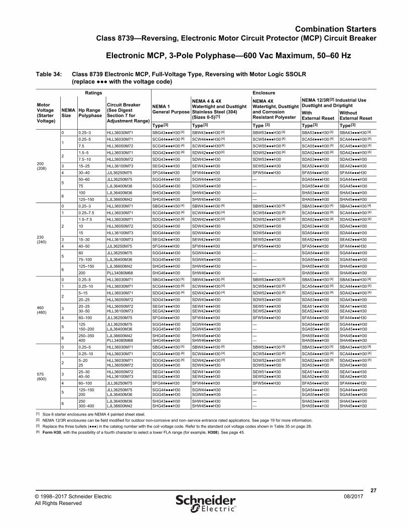
Combination StartersClass 8739—Reversing, Electronic Motor Circuit Protector (MCP) Circuit Breaker
2708/2017© 1998–2017 Schneider Electric
All Rights Reserved™
Electronic MCP, 3-Pole Polyphase—600 Vac Maximum, 50–60 Hz
Table 34: Class 8739 Electronic MCP, Full-Voltage Type, Reversing with Motor Logic SSOLR (replace ●●● with the voltage code)
Ratings Enclosure
MotorVoltage(StarterVoltage)
NEMASize
Hp RangePolyphase
Circuit Breaker(See Digest Section 7 for Adjustment Range)
NEMA 1General Purpose
NEMA 4 & 4XWatertight and Dusttight Stainless Steel (304)(Sizes 0-5)[1]
NEMA 4XWatertight, Dusttight and Corrosion Resistant Polyester
NEMA 12/3R[2] Industrial Use Dusttight and Driptight
WithExternal Reset
WithoutExternal Reset
Type[3] Type[3] Type [3] Type[3] Type[3]
200(208)
0 0.25–3 HLL36030M71 SBG43●●●H30 [4] SBW43●●●H30 [4] SBW53●●●H30 [4] SBA53●●●H30 [4] SBA43●●●H30 [4]
10.25–5 HLL36030M71 SCG44●●●H30 [4] SCW44●●●H30 [4] SCW54●●●H30 [4] SCA54●●●H30 [4] SCA44●●●H30 [4]
7.5 HLL36050M72 SCG45●●●H30 [4] SCW45●●●H30[4] SCW55●●●H30 [4] SCA55●●●H30 [4] SCA45●●●H30 [4]
21.5–5 HLL36030M71 SDG42●●●H30 [4] SDW42●●●H30[4] SDW52●●●H30 [4] SDA52●●●H30 [4] SDA42●●●H30 [4]
7.5–10 HLL36050M72 SDG43●●●H30 SDW43●●●H30 SDW53●●●H30 SDA53●●●H30 SDA43●●●H30
3 15–25 HLL36100M73 SEG42●●●H30 SEW42●●●H30 SEW52●●●H30 SEA52●●●H30 SEA42●●●H30
4 30–40 JJL36250M75 SFG44●●●H30 SFW44●●●H30 SFW54●●●H30 SFA54●●●H30 SFA44●●●H30
550–60 JLL36250M75 SGG44●●●H30 SGW44●●●H30 — SGA54●●●H30 SGA44●●●H30
75 LJL36400M36 SGG45●●●H30 SGW45●●●H30 — SGA55●●●H30 SGA45●●●H30
6100 LJL36400M36 SHG43●●●H30 SHW43●●●H30 — SHA53●●●H30 SHA43●●●H30
125–150 LJL36600M42 SHG45●●●H30 SHW45●●●H30 — SHA55●●●H30 SHA45●●●H30
230(240)
0 0.25–3 HLL36030M71 SBG43●●●H30 [4] SBW43●●●H30 [4] SBW53●●●H30 [4] SBA53●●●H30 [4] SBA43●●●H30 [4]
1 0.25–7.5 HLL36030M71 SCG44●●●H30 [4] SCW44●●●H30 [4] SCW54●●●H30 [4] SCA54●●●H30 [4] SCA44●●●H30 [4]
2
1.5–7.5 HLL36030M71 SDG42●●●H30 [4] SDW42●●●H30 [4] SDW52●●●H30 [4] SDA52●●●H30 [4] SDA42●●●H30 [4]
10 HLL36050M72 SDG43●●●H30 SDW43●●●H30 SDW53●●●H30 SDA53●●●H30 SDA43●●●H30
15 HLL36100M73 SDG44●●●H30 SDW44●●●H30 SDW54●●●H30 SDA54●●●H30 SDA44●●●H30
3 15–30 HLL36100M73 SEG42●●●H30 SEW42●●●H30 SEW52●●●H30 SEA52●●●H30 SEA42●●●H30
4 40–50 JJL36250M75 SFG44●●●H30 SFW44●●●H30 SFW54●●●H30 SFA54●●●H30 SFA44●●●H30
560 JLL36250M75 SGG44●●●H30 SGW44●●●H30 — SGA54●●●H30 SGA44●●●H30
75–100 LJL36400M36 SGG45●●●H30 SGW45●●●H30 — SGA55●●●H30 SGA45●●●H30
6125–150 LJL36600M42 SHG45●●●H30 SHW45●●●H30 — SHA55●●●H30 SHA45●●●H30
200 PLL34080M68 SHG46●●●H30 SHW46●●●H30 — SHA56●●●H30 SHA46●●●H30
460(480)
0 0.25–5 HLL36030M71 SBG43●●●H30 [4] SBW43●●●H30 [4] SBW53●●●H30 [4] SBA53●●●H30 [4] SBA43●●●H30 [4]
1 0.25–10 HLL36030M71 SCG44●●●H30 [4] SCW44●●●H30 [4] SCW54●●●H30 [4] SCA54●●●H30 [4] SCA44●●●H30 [4]
25–15 HLL36030M71 SDG42●●●H30 [4] SDW42●●●H30 [4] SDW52●●●H30 [4] SDA52●●●H30 [4] SDA42●●●H30 [4]
20–25 HLL36050M72 SDG43●●●H30 SDW43●●●H30 SDW53●●●H30 SDA53●●●H30 SDA43●●●H30
320–2530–50
HLL36050M72HLL36100M73
SEG41●●●H30 SEG42●●●H30
SEW41●●●H30 SEW42●●●H30
SEW51●●●H30 SEW52●●●H30
SEA51●●●H30 SEA52●●●H30
SEA41●●●H30 SEA42●●●H30
4 60–100 JLL36250M75 SFG44●●●H30 SFW44●●●H30 SFW54●●●H30 SFA54●●●H30 SFA44●●●H30
5125150–200
JLL36250M75LJL36400M36
SGG44●●●H30 SGG45●●●H30
SGW44●●●H30 SGW45●●●H30
——
SGA54●●●H30 SGA55●●●H30
SGA44●●●H30 SGA45●●●H30
6250–350400
LJL36600M42PLL34080M68
SHG45●●●H30 SHG46●●●H30
SHW45●●●H30 SHW46●●●H30
——
SHA55●●●H30 SHA56●●●H30
SHA45●●●H30 SHA46●●●H30
575(600)
0 0.25–5 HLL36030M71 SBG43●●●H30 [4] SBW43●●●H30 [4] SBW53●●●H30 [4] SBA53●●●H30 [4] SBA43●●●H30 [4]
1 0.25–10 HLL36030M71 SCG44●●●H30 [4] SCW44●●●H30 [4] SCW54●●●H30 [4] SCA54●●●H30 [4] SCA44●●●H30 [4]
25–2025
HLL36030M71HLL36050M72
SDG42●●●H30 [4] SDG43●●●H30
SDW42●●●H30 [4] SDW43●●●H30
SDW52●●●H30 [4] SDW53●●●H30
SDA52●●●H30 [4] SDA53●●●H30
SDA42●●●H30 [4] SDA43●●●H30
325–3040–50
HLL36050M72HLL36100M73
SEG41●●●H30 SEG42●●●H30
SEW41●●●H30 SEW42●●●H30
SEW51●●●H30 SEW52●●●H30
SEA51●●●H30 SEA52●●●H30
SEA41●●●H30SEA42●●●H30
4 60–100 JLL36250M75 SFG44●●●H30 SFW44●●●H30 SFW54●●●H30 SFA54●●●H30 SFA44●●●H30
5125–150200
JLL36250M75LJL36400M36
SGG44●●●H30SGG45●●●H30
SGW44●●●H30 SGW45●●●H30
——
SGA54●●●H30 SGA55●●●H30
SGA44●●●H30 SGA45●●●H30
6250300–400
LJL36400M36LJL36600M42
SHG43●●●H30SHG45●●●H30
SHW43●●●H30 SHW45●●●H30
——
SHA53●●●H30 SHA55●●●H30
SHA43●●●H30 SHA45●●●H30
[1] Size 6 starter enclosures are NEMA 4 painted sheet steel.[2] NEMA 12/3R enclosures can be field modified for outdoor non-corrosive and non–service entrance rated applications. See page 19 for more information.[3] Replace the three bullets (●●●) in the catalog number with the coil voltage code. Refer to the standard coil voltage codes shown in Table 35 on page 28.[4] Form H30, with the possibility of a fourth character to select a lower FLA range (for example, H308). See page 45.
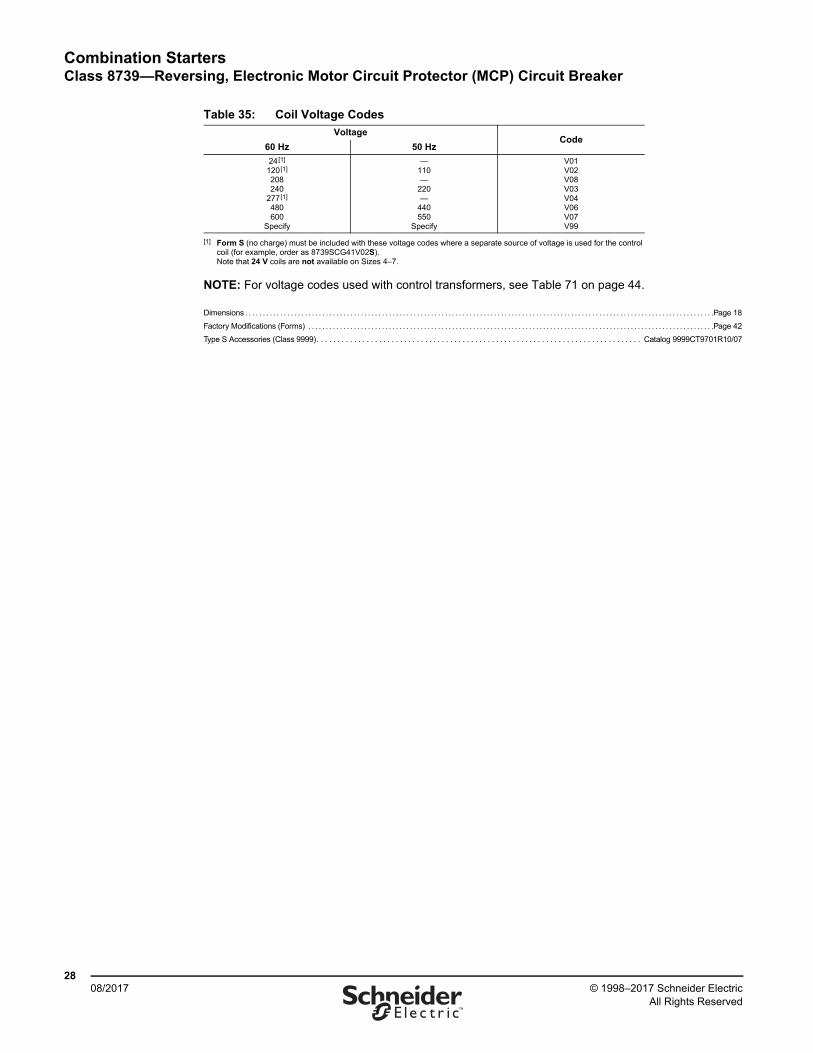
Combination StartersClass 8739—Reversing, Electronic Motor Circuit Protector (MCP) Circuit Breaker
2808/2017 © 1998–2017 Schneider Electric
All Rights Reserved™
NOTE: For voltage codes used with control transformers, see Table 71 on page 44.
Dimensions . . . . . . . . . . . . . . . . . . . . . . . . . . . . . . . . . . . . . . . . . . . . . . . . . . . . . . . . . . . . . . . . . . . . . . . . . . . . . . . . . . . . . . . . . . . . . . . . . . . . . . . . . . . . . . . . . . . . . . . . . . . . . . . . . . . . . .Page 18
Factory Modifications (Forms) . . . . . . . . . . . . . . . . . . . . . . . . . . . . . . . . . . . . . . . . . . . . . . . . . . . . . . . . . . . . . . . . . . . . . . . . . . . . . . . . . . . . . . . . . . . . . . . . . . . . . . . . . . . . . . . . . . . .Page 42
Type S Accessories (Class 9999). . . . . . . . . . . . . . . . . . . . . . . . . . . . . . . . . . . . . . . . . . . . . . . . . . . . . . . . . . . . . . . . . . . . . . . . . . . . . . Catalog 9999CT9701R10/07
Table 35: Coil Voltage Codes
VoltageCode
60 Hz 50 Hz
24[1]
120[1]
208240
277[1]
480600
Specify
[1] Form S (no charge) must be included with these voltage codes where a separate source of voltage is used for the control coil (for example, order as 8739SCG41V02S). Note that 24 V coils are not available on Sizes 4–7.
—110—
220—
440550
Specify
V01V02V08V03V04V06V07V99
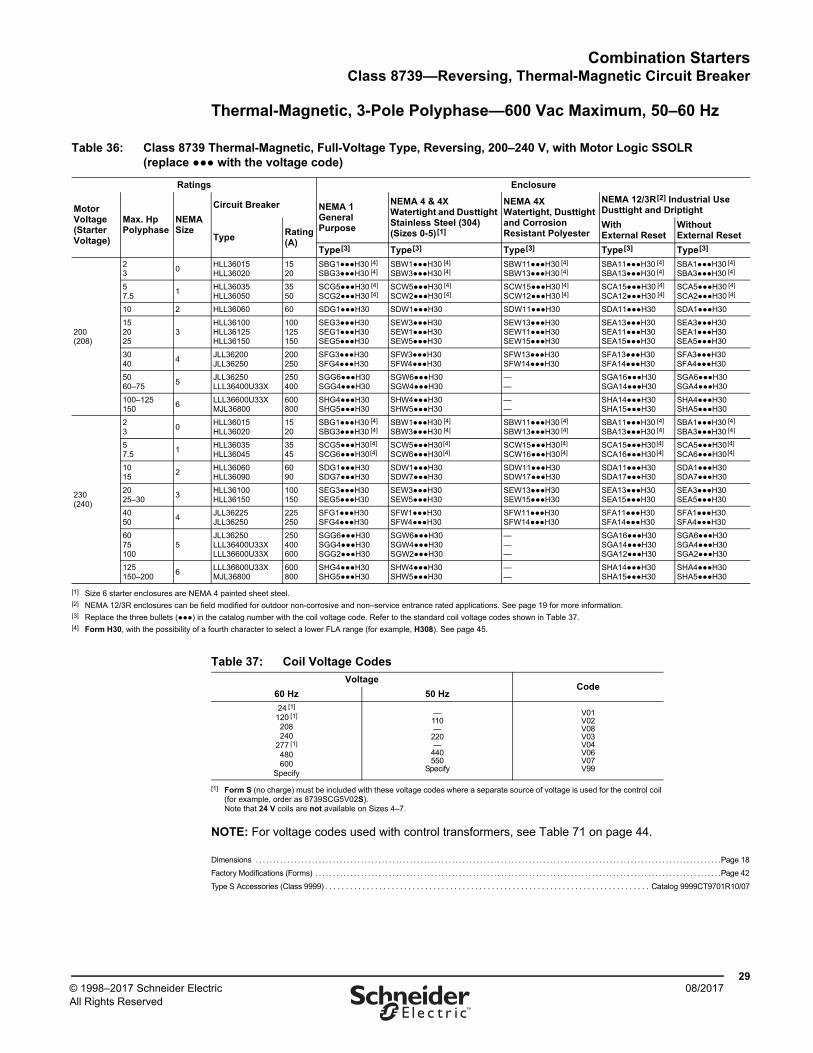
Combination StartersClass 8739—Reversing, Thermal-Magnetic Circuit Breaker
2908/2017© 1998–2017 Schneider Electric
All Rights Reserved™
Thermal-Magnetic, 3-Pole Polyphase—600 Vac Maximum, 50–60 Hz
NOTE: For voltage codes used with control transformers, see Table 71 on page 44.
Dimensions . . . . . . . . . . . . . . . . . . . . . . . . . . . . . . . . . . . . . . . . . . . . . . . . . . . . . . . . . . . . . . . . . . . . . . . . . . . . . . . . . . . . . . . . . . . . . . . . . . . . . . . . . . . . . . . . . . . . . . . . . . . . . . . . . . . . .Page 18
Factory Modifications (Forms) . . . . . . . . . . . . . . . . . . . . . . . . . . . . . . . . . . . . . . . . . . . . . . . . . . . . . . . . . . . . . . . . . . . . . . . . . . . . . . . . . . . . . . . . . . . . . . . . . . . . . . . . . . . . . . . . . . . .Page 42
Type S Accessories (Class 9999) . . . . . . . . . . . . . . . . . . . . . . . . . . . . . . . . . . . . . . . . . . . . . . . . . . . . . . . . . . . . . . . . . . . . . . . . . . . . . . Catalog 9999CT9701R10/07
Table 36: Class 8739 Thermal-Magnetic, Full-Voltage Type, Reversing, 200–240 V, with Motor Logic SSOLR (replace ●●● with the voltage code)
Ratings Enclosure
MotorVoltage(StarterVoltage)
Max. HpPolyphase
NEMASize
Circuit Breaker NEMA 1General Purpose
NEMA 4 & 4XWatertight and Dusttight Stainless Steel (304)(Sizes 0-5)[1]
NEMA 4XWatertight, Dusttight and Corrosion Resistant Polyester
NEMA 12/3R[2] Industrial UseDusttight and Driptight
TypeRating (A)
WithExternal Reset
WithoutExternal Reset
Type[3] Type[3] Type[3] Type[3] Type[3]
200(208)
23
0HLL36015HLL36020
1520
SBG1●●●H30 [4]
SBG3●●●H30 [4] SBW1●●●H30 [4] SBW3●●●H30 [4]
SBW11●●●H30 [4] SBW13●●●H30 [4]
SBA11●●●H30 [4] SBA13●●●H30 [4]
SBA1●●●H30 [4] SBA3●●●H30 [4]
57.5
1HLL36035HLL36050
3550
SCG5●●●H30 [4] SCG2●●●H30 [4]
SCW5●●●H30 [4] SCW2●●●H30 [4]
SCW15●●●H30 [4] SCW12●●●H30 [4]
SCA15●●●H30 [4] SCA12●●●H30 [4]
SCA5●●●H30 [4] SCA2●●●H30 [4]
10 2 HLL36060 60 SDG1●●●H30 SDW1●●●H30 SDW11●●●H30 SDA11●●●H30 SDA1●●●H30
152025
3HLL36100HLL36125HLL36150
100125150
SEG3●●●H30 SEG1●●●H30 SEG5●●●H30
SEW3●●●H30 SEW1●●●H30 SEW5●●●H30
SEW13●●●H30 SEW11●●●H30 SEW15●●●H30
SEA13●●●H30 SEA11●●●H30 SEA15●●●H30
SEA3●●●H30 SEA1●●●H30 SEA5●●●H30
3040
4JLL36200JLL36250
200250
SFG3●●●H30 SFG4●●●H30
SFW3●●●H30 SFW4●●●H30
SFW13●●●H30 SFW14●●●H30
SFA13●●●H30 SFA14●●●H30
SFA3●●●H30 SFA4●●●H30
5060–75
5JLL36250LLL36400U33X
250400
SGG6●●●H30 SGG4●●●H30
SGW6●●●H30 SGW4●●●H30
——
SGA16●●●H30 SGA14●●●H30
SGA6●●●H30 SGA4●●●H30
100–125150
6LLL36600U33XMJL36800
600800
SHG4●●●H30 SHG5●●●H30
SHW4●●●H30 SHW5●●●H30
——
SHA14●●●H30 SHA15●●●H30
SHA4●●●H30SHA5●●●H30
230(240)
23
0HLL36015HLL36020
1520
SBG1●●●H30 [4] SBG3●●●H30 [4]
SBW1●●●H30 [4] SBW3●●●H30 [4]
SBW11●●●H30 [4] SBW13●●●H30 [4]
SBA11●●●H30 [4] SBA13●●●H30 [4]
SBA1●●●H30 [4] SBA3●●●H30 [4]
57.5
1HLL36035HLL36045
3545
SCG5●●●H30[4] SCG6●●●H30[4]
SCW5●●●H30[4] SCW6●●●H30[4]
SCW15●●●H30[4] SCW16●●●H30[4]
SCA15●●●H30[4] SCA16●●●H30[4]
SCA5●●●H30[4] SCA6●●●H30[4]
1015
2HLL36060HLL36090
6090
SDG1●●●H30 SDG7●●●H30
SDW1●●●H30 SDW7●●●H30
SDW11●●●H30 SDW17●●●H30
SDA11●●●H30 SDA17●●●H30
SDA1●●●H30 SDA7●●●H30
2025–30
3HLL36100HLL36150
100150
SEG3●●●H30 SEG5●●●H30
SEW3●●●H30 SEW5●●●H30
SEW13●●●H30 SEW15●●●H30
SEA13●●●H30 SEA15●●●H30
SEA3●●●H30 SEA5●●●H30
4050
4JLL36225JLL36250
225250
SFG1●●●H30 SFG4●●●H30
SFW1●●●H30 SFW4●●●H30
SFW11●●●H30 SFW14●●●H30
SFA11●●●H30 SFA14●●●H30
SFA1●●●H30 SFA4●●●H30
6075100
5JLL36250LLL36400U33XLLL36600U33X
250400600
SGG6●●●H30 SGG4●●●H30 SGG2●●●H30
SGW6●●●H30 SGW4●●●H30 SGW2●●●H30
———
SGA16●●●H30 SGA14●●●H30 SGA12●●●H30
SGA6●●●H30 SGA4●●●H30 SGA2●●●H30
125150–200
6LLL36600U33XMJL36800
600800
SHG4●●●H30 SHG5●●●H30
SHW4●●●H30 SHW5●●●H30
——
SHA14●●●H30 SHA15●●●H30
SHA4●●●H30 SHA5●●●H30
[1] Size 6 starter enclosures are NEMA 4 painted sheet steel.[2] NEMA 12/3R enclosures can be field modified for outdoor non-corrosive and non–service entrance rated applications. See page 19 for more information.[3] Replace the three bullets (●●●) in the catalog number with the coil voltage code. Refer to the standard coil voltage codes shown in Table 37.[4] Form H30, with the possibility of a fourth character to select a lower FLA range (for example, H308). See page 45.
Table 37: Coil Voltage Codes
VoltageCode
60 Hz 50 Hz
24 [1]
120 [1] 208240
277 [1] 480600
Specify
[1] Form S (no charge) must be included with these voltage codes where a separate source of voltage is used for the control coil (for example, order as 8739SCG5V02S). Note that 24 V coils are not available on Sizes 4–7.
—110—
220—
440550
Specify
V01V02V08V03V04V06V07V99
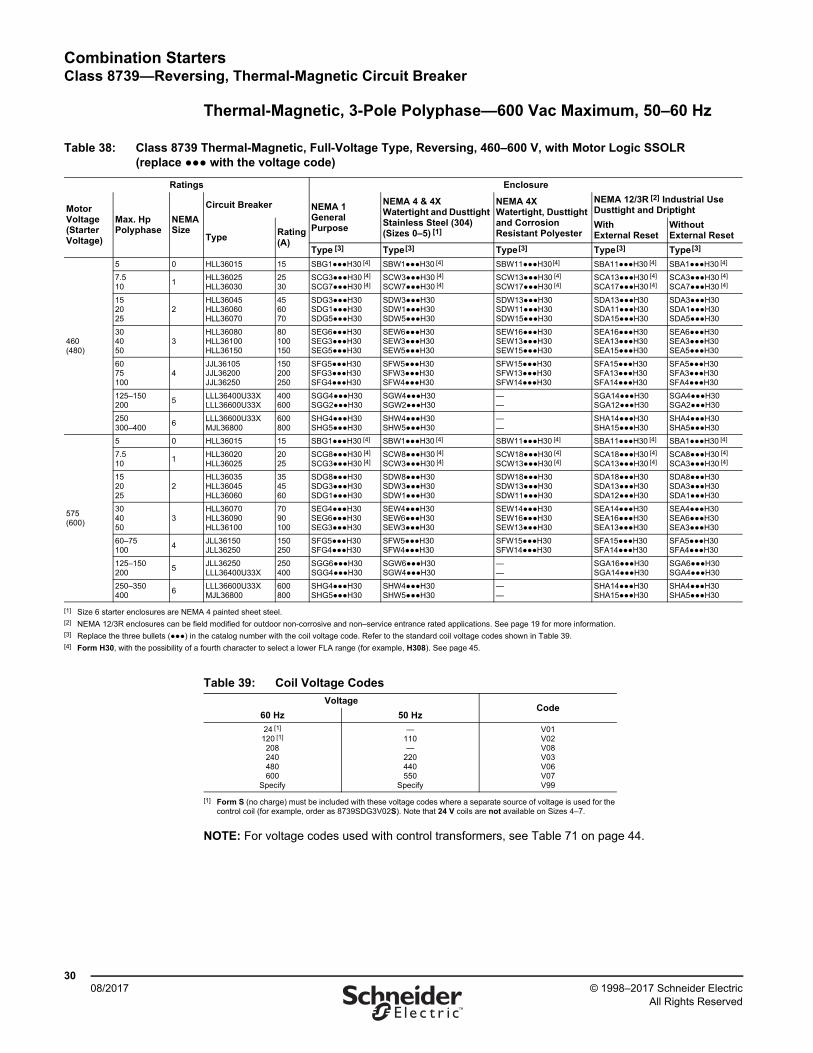
Combination StartersClass 8739—Reversing, Thermal-Magnetic Circuit Breaker
3008/2017 © 1998–2017 Schneider Electric
All Rights Reserved™
Thermal-Magnetic, 3-Pole Polyphase—600 Vac Maximum, 50–60 Hz
NOTE: For voltage codes used with control transformers, see Table 71 on page 44.
Table 38: Class 8739 Thermal-Magnetic, Full-Voltage Type, Reversing, 460–600 V, with Motor Logic SSOLR (replace ●●● with the voltage code)
Ratings Enclosure
MotorVoltage(StarterVoltage)
Max. HpPolyphase
NEMASize
Circuit Breaker NEMA 1General Purpose
NEMA 4 & 4XWatertight and Dusttight Stainless Steel (304)(Sizes 0–5) [1]
NEMA 4XWatertight, Dusttight and Corrosion Resistant Polyester
NEMA 12/3R [2] Industrial UseDusttight and Driptight
TypeRating (A)
WithExternal Reset
WithoutExternal Reset
Type [3] Type[3] Type[3] Type[3] Type[3]
460(480)
5 0 HLL36015 15 SBG1●●●H30 [4] SBW1●●●H30 [4] SBW11●●●H30[4] SBA11●●●H30 [4] SBA1●●●H30 [4]
7.510
1HLL36025HLL36030
2530
SCG3●●●H30 [4] SCG7●●●H30 [4]
SCW3●●●H30 [4] SCW7●●●H30 [4]
SCW13●●●H30 [4] SCW17●●●H30 [4]
SCA13●●●H30 [4] SCA17●●●H30 [4]
SCA3●●●H30 [4] SCA7●●●H30 [4]
152025
2HLL36045HLL36060HLL36070
456070
SDG3●●●H30 SDG1●●●H30 SDG5●●●H30
SDW3●●●H30 SDW1●●●H30 SDW5●●●H30
SDW13●●●H30 SDW11●●●H30 SDW15●●●H30
SDA13●●●H30 SDA11●●●H30 SDA15●●●H30
SDA3●●●H30 SDA1●●●H30 SDA5●●●H30
304050
3HLL36080HLL36100HLL36150
80100150
SEG6●●●H30SEG3●●●H30SEG5●●●H30
SEW6●●●H30SEW3●●●H30SEW5●●●H30
SEW16●●●H30SEW13●●●H30SEW15●●●H30
SEA16●●●H30SEA13●●●H30SEA15●●●H30
SEA6●●●H30SEA3●●●H30SEA5●●●H30
6075100
4JJL36105JJL36200JJL36250
150200250
SFG5●●●H30SFG3●●●H30SFG4●●●H30
SFW5●●●H30SFW3●●●H30SFW4●●●H30
SFW15●●●H30SFW13●●●H30SFW14●●●H30
SFA15●●●H30SFA13●●●H30SFA14●●●H30
SFA5●●●H30SFA3●●●H30SFA4●●●H30
125–150200
5LLL36400U33XLLL36600U33X
400600
SGG4●●●H30SGG2●●●H30
SGW4●●●H30SGW2●●●H30
——
SGA14●●●H30SGA12●●●H30
SGA4●●●H30SGA2●●●H30
250300–400
6LLL36600U33XMJL36800
600800
SHG4●●●H30SHG5●●●H30
SHW4●●●H30SHW5●●●H30
——
SHA14●●●H30SHA15●●●H30
SHA4●●●H30SHA5●●●H30
575(600)
5 0 HLL36015 15 SBG1●●●H30 [4] SBW1●●●H30 [4] SBW11●●●H30 [4] SBA11●●●H30 [4] SBA1●●●H30 [4]
7.510
1HLL36020HLL36025
2025
SCG8●●●H30 [4] SCG3●●●H30 [4]
SCW8●●●H30 [4] SCW3●●●H30 [4]
SCW18●●●H30 [4] SCW13●●●H30 [4]
SCA18●●●H30 [4] SCA13●●●H30 [4]
SCA8●●●H30 [4] SCA3●●●H30 [4]
152025
2HLL36035HLL36045HLL36060
354560
SDG8●●●H30SDG3●●●H30SDG1●●●H30
SDW8●●●H30SDW3●●●H30SDW1●●●H30
SDW18●●●H30SDW13●●●H30SDW11●●●H30
SDA18●●●H30SDA13●●●H30SDA12●●●H30
SDA8●●●H30SDA3●●●H30SDA1●●●H30
304050
3HLL36070HLL36090HLL36100
7090100
SEG4●●●H30SEG6●●●H30SEG3●●●H30
SEW4●●●H30SEW6●●●H30SEW3●●●H30
SEW14●●●H30SEW16●●●H30SEW13●●●H30
SEA14●●●H30SEA16●●●H30SEA13●●●H30
SEA4●●●H30SEA6●●●H30SEA3●●●H30
60–75100
4JLL36150JLL36250
150250
SFG5●●●H30SFG4●●●H30
SFW5●●●H30SFW4●●●H30
SFW15●●●H30SFW14●●●H30
SFA15●●●H30SFA14●●●H30
SFA5●●●H30SFA4●●●H30
125–150200
5JLL36250LLL36400U33X
250400
SGG6●●●H30SGG4●●●H30
SGW6●●●H30SGW4●●●H30
——
SGA16●●●H30SGA14●●●H30
SGA6●●●H30SGA4●●●H30
250–350400
6LLL36600U33XMJL36800
600800
SHG4●●●H30SHG5●●●H30
SHW4●●●H30SHW5●●●H30
——
SHA14●●●H30SHA15●●●H30
SHA4●●●H30SHA5●●●H30
[1] Size 6 starter enclosures are NEMA 4 painted sheet steel.[2] NEMA 12/3R enclosures can be field modified for outdoor non-corrosive and non–service entrance rated applications. See page 19 for more information.[3] Replace the three bullets (●●●) in the catalog number with the coil voltage code. Refer to the standard coil voltage codes shown in Table 39.[4] Form H30, with the possibility of a fourth character to select a lower FLA range (for example, H308). See page 45.
Table 39: Coil Voltage Codes
VoltageCode
60 Hz 50 Hz
24 [1]
120 [1] 208240480600
Specify
[1] Form S (no charge) must be included with these voltage codes where a separate source of voltage is used for the control coil (for example, order as 8739SDG3V02S). Note that 24 V coils are not available on Sizes 4–7.
—110—
220440550
Specify
V01V02V08V03V06V07V99
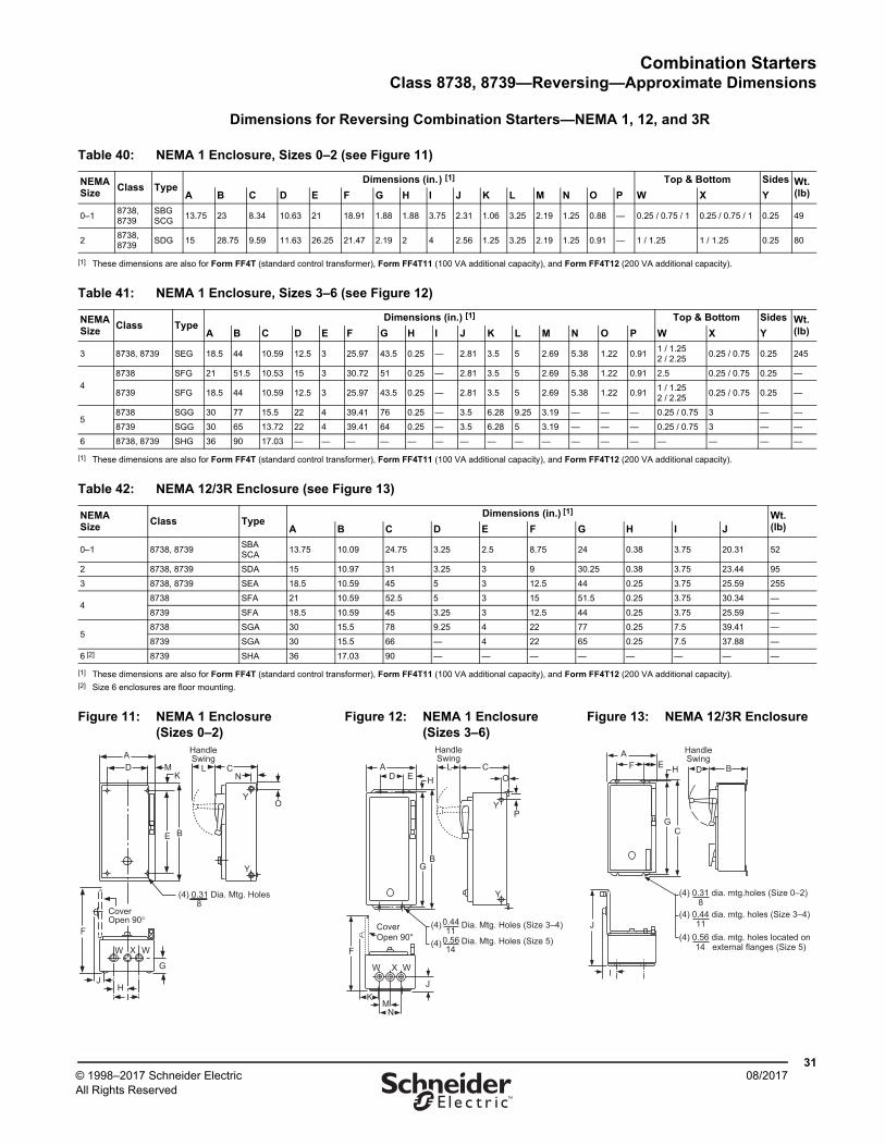
Combination StartersClass 8738, 8739—Reversing—Approximate Dimensions
3108/2017© 1998–2017 Schneider Electric
All Rights Reserved™
Dimensions for Reversing Combination Starters—NEMA 1, 12, and 3R
Table 40: NEMA 1 Enclosure, Sizes 0–2 (see Figure 11)
NEMASize
Class TypeDimensions (in.) [1] Top & Bottom Sides Wt.
(lb)A B C D E F G H I J K L M N O P W X Y
0–18738, 8739
SBGSCG
13.75 23 8.34 10.63 21 18.91 1.88 1.88 3.75 2.31 1.06 3.25 2.19 1.25 0.88 — 0.25 / 0.75 / 1 0.25 / 0.75 / 1 0.25 49
28738, 8739
SDG 15 28.75 9.59 11.63 26.25 21.47 2.19 2 4 2.56 1.25 3.25 2.19 1.25 0.91 — 1 / 1.25 1 / 1.25 0.25 80
[1] These dimensions are also for Form FF4T (standard control transformer), Form FF4T11 (100 VA additional capacity), and Form FF4T12 (200 VA additional capacity).
Table 41: NEMA 1 Enclosure, Sizes 3–6 (see Figure 12)
NEMASize
Class TypeDimensions (in.) [1] Top & Bottom Sides Wt.
(lb)A B C D E F G H I J K L M N O P W X Y
3 8738, 8739 SEG 18.5 44 10.59 12.5 3 25.97 43.5 0.25 — 2.81 3.5 5 2.69 5.38 1.22 0.911 / 1.252 / 2.25
0.25 / 0.75 0.25 245
4
8738 SFG 21 51.5 10.53 15 3 30.72 51 0.25 — 2.81 3.5 5 2.69 5.38 1.22 0.91 2.5 0.25 / 0.75 0.25 —
8739 SFG 18.5 44 10.59 12.5 3 25.97 43.5 0.25 — 2.81 3.5 5 2.69 5.38 1.22 0.911 / 1.252 / 2.25
0.25 / 0.75 0.25 —
58738 SGG 30 77 15.5 22 4 39.41 76 0.25 — 3.5 6.28 9.25 3.19 — — — 0.25 / 0.75 3 — —
8739 SGG 30 65 13.72 22 4 39.41 64 0.25 — 3.5 6.28 5 3.19 — — — 0.25 / 0.75 3 — —
6 8738, 8739 SHG 36 90 17.03 — — — — — — — — — — — — — — — — —
[1] These dimensions are also for Form FF4T (standard control transformer), Form FF4T11 (100 VA additional capacity), and Form FF4T12 (200 VA additional capacity).
Table 42: NEMA 12/3R Enclosure (see Figure 13)
NEMASize
Class TypeDimensions (in.) [1] Wt.
(lb)A B C D E F G H I J
0–1 8738, 8739SBASCA
13.75 10.09 24.75 3.25 2.5 8.75 24 0.38 3.75 20.31 52
2 8738, 8739 SDA 15 10.97 31 3.25 3 9 30.25 0.38 3.75 23.44 95
3 8738, 8739 SEA 18.5 10.59 45 5 3 12.5 44 0.25 3.75 25.59 255
48738 SFA 21 10.59 52.5 5 3 15 51.5 0.25 3.75 30.34 —
8739 SFA 18.5 10.59 45 3.25 3 12.5 44 0.25 3.75 25.59 —
58738 SGA 30 15.5 78 9.25 4 22 77 0.25 7.5 39.41 —
8739 SGA 30 15.5 66 — 4 22 65 0.25 7.5 37.88 —
6 [2] 8739 SHA 36 17.03 90 — — — — — — — —
[1] These dimensions are also for Form FF4T (standard control transformer), Form FF4T11 (100 VA additional capacity), and Form FF4T12 (200 VA additional capacity).[2] Size 6 enclosures are floor mounting.
Figure 11: NEMA 1 Enclosure (Sizes 0–2)
Figure 12: NEMA 1 Enclosure (Sizes 3–6)
Figure 13: NEMA 12/3R Enclosure
YO
NC
HandleSwing
E B
KMD
A
Y
(4) 0.31 Dia. Mtg. Holes8
F
W X W
GJ
HI
Cover Open 90°
LD
AE H
L
HandleSwing
C
P
O
Y
BG
Y
J
NM
K
W X W
F
Dia. Mtg. Holes (Size 3–4)
Dia. Mtg. Holes (Size 5)
0.4411
0.5614
(4)
(4)
Cover Open 90°
B
HandleSwing
C
FA
(4) 0.31 dia. mtg.holes (Size 0–2)8
(4) 0.44 dia. mtg. holes (Size 3–4)11
(4) 0.56 dia. mtg. holes located on14 external flanges (Size 5)
J
I
DE
G
H
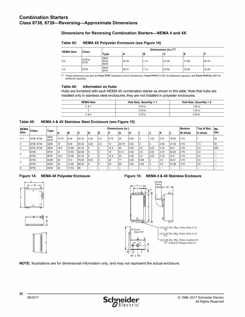
Combination StartersClass 8738, 8739—Reversing—Approximate Dimensions
3208/2017 © 1998–2017 Schneider Electric
All Rights Reserved™
Dimensions for Reversing Combination Starters—NEMA 4 and 4X
Table 43: NEMA 4X Polyester Enclosure (see Figure 14)
NEMA Size ClassDimensions (in.) [1]
[1] These dimensions are also for Form FF4T (standard control transformer), Form FF4T11 (100 VA additional capacity), and Form FF4T12 (200 VA additional capacity).
Type A B C E F
0-28738 &8739
SBWSCWSDW
25.25 11.4 27.00 17.88 25.75
3-4 8739SEWSFW
26.31 11.4 33.50 18.50 32.25
Table 44: Information on HubsHubs are furnished with each NEMA 4X combination starter as shown in this table. Note that hubs are installed only in stainless steel enclosures; they are not installed in polyester enclosures.
NEMA Size Hub Size, Quantity = 1 Hub Size, Quantity = 2
0 & 1 0.75 in. 1.00 in.
2 0.75 in. 1.50 in.
3 & 4 0.75 in. 2.50 in.
Table 45: NEMA 4 & 4X Stainless Steel Enclosure (see Figure 15)
NEMASize
Class TypeDimensions (in.) Bottom Top & Bot. Wt.
(lb)A B C D E F G H I J K L W (Hub) X (Hub)
0–1 8738, 8739SBWSCW
13.75 8.34 25.19 3.25 2.5 8.75 24 0.59 3 1.63 2.31 18.53 0.75 1 52
2 8738, 8739 SDW 15 9.59 30.03 3.25 2.5 10 29.75 0.63 3 2 2.63 21.03 0.75 1.5 95
3 8738, 8739 SEW 18.5 10.56 45.19 5 3 12.5 44 0.59 3.5 2.63 3.19 25.5 0.75 2.5 255
48738 SFW 21 10.53 52.69 5 3 15 51.5 0.59 3.5 2.63 3.19 30.25 0.75 2.5 —
8739 SFW 18.5 10.56 45.19 5 3 12.5 44 0.59 3.5 2.63 3.19 25.5 0.75 2.5 —
58738 SGW 30 15.5 78.09 9.25 4 22 77 0.56 6.09 3 3.5 39.41 0.75 3.5 —
8739 SGW 30 13.89 66.09 5 4 22 65 0.56 6.09 3 3.5 37.88 0.75 3.5 —
6 8739 SHW 36 17.03 98 — — — — — — — — — — — —
Figure 14: NEMA 4X Polyester Enclosure Figure 15: NEMA 4 & 4X Stainless Enclosure
NOTE: Illustrations are for dimensional information only, and may not represent the actual enclosure.
AE
F
C
B
B
HandleSwing
C
FA
(4) 0.31 Dia. Mtg. Holes (Size 0–2)8
(4) 0.44 Dia. Mtg. Holes (Size 3–4)11
(4) 0.56 Dia. Mtg. Holes Located On14 External Flanges (Size 5)
L
W X
I
Cover Open 90°
DE
K
J
G
H
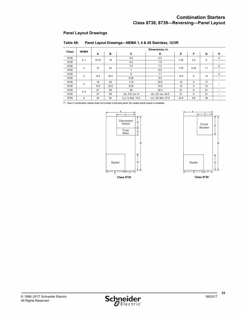
Combination StartersClass 8738, 8739—Reversing—Panel Layout
3308/2017© 1998–2017 Schneider Electric
All Rights Reserved™
Panel Layout Drawings
Table 46: Panel Layout Drawings—NEMA 1, 4 & 4X Stainless, 12/3R
Class NEMADimensions, in.
A B C D E F G H
87380, 1 10.75 19
6.9 6.57.25 3.5 9
4
8739 6.5 7.9 –
87382 12 24
7.5 7.07.75 4.25 11
6
8739 7 8.8 –
87383 15.5 32.5
9 7.715.5 0 14
5
8739 8.25 8.5 –
87384
18 39 11.5 20.5 18 0 17–
8739 15.5 32.5 9.25 10.5 15 0 15
87385 [1]
[1] Size 5 combination starter does not contain a full-size panel. No usable panel space is available.
27 59 26 25.0 21 6 21 –
8739 27 58 JLL: 6.8; LLL: 9 JLL: 23; LLL: 24.5 21 6 21 –
8739 6 32 82 LLL: 9; MJL: 12.5 LLL: 26; MJL: 27.5 22.5 9.5 36 –
Class 8738
C
DisconnectSwitch
FuseBase
Starter
FE
A
G
D
B
H
Class 8739
C
FE
Starter
Circuit Breaker
A
G
D
B
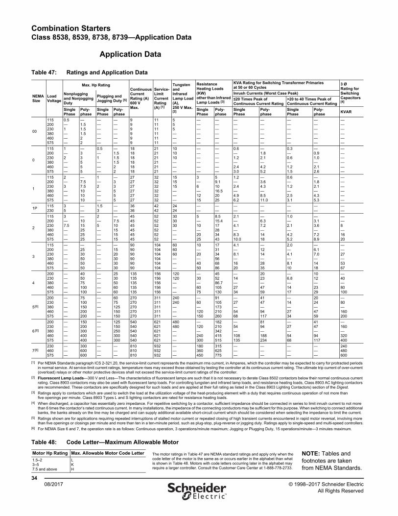
Combination StartersClass 8538, 8539, 8738, 8739—Application Data
3408/2017 © 1998–2017 Schneider Electric
All Rights Reserved™
Application Data
Table 47: Ratings and Application Data
NEMA Size
Load Voltage
Max. Hp RatingContinuous Current Rating (A)600 VMax.
Service-Limit Current Rating(A) [1]
Tungsten and Infrared Lamp Load (A),250 V Max. [2]
Resistance Heating Loads(KW)other than Infrared Lamp Loads [3]
KVA Rating for Switching Transformer Primaries at 50 or 60 Cycles
3 ØRating for Switching Capacitors [4]
Nonplugging and Nonjogging Duty
Plugging and Jogging Duty [5]
Inrush Currents (Worst Case Peak)
≤20 Times Peak of Continuous Current Rating
>20 to 40 Times Peak of Continuous Current Rating
SinglePhase
Poly-phase
SinglePhase
Poly-phase
SinglePhase
Poly-phase
SinglePhase
Poly-phase
SinglePhase
Poly-phase
KVAR
00
115200230380460575
0.5—1———
—1.51.51.522
——————
——————
999999
111111111111
555———
——————
——————
——————
——————
——————
——————
——————
0
115200230380460575
1—2———
—33555
0.5—1———
—1.51.51.522
181818181818
212121212121
101010———
——————
——————
0.6—1.2—2.43.0
—1.82.1—4.25.2
0.3—0.6—1.21.5
—0.91.0—2.12.6
——————
1
115200230380460575
2—3———
—7.57.5101010
1—2———
—33555
272727272727
323232323232
151515———
3—6—1215
59.11016.52025
1.2—2.4—4.96.2
—3.64.3—8.511.0
0.6—1.2—2.53.1
—1.82.1—4.35.3
——————
1P115230
35
——
1.53
——
3636
4242
2424
——
——
——
——
——
——
——
2
115200230380460575
3—7.5———
—1015252525
2—5———
—7.510151515
454545454545
525252525252
303030———
5—10—2025
8.515.417283443
2.1—4.1—8.310.0
—6.37.2—1418
1.0—2.1—4.25.2
—3.13.6—7.28.9
——8—1620
3
115200230380460575
——————
—2530505050
——————
—1520303030
909090909090
104104104104104104
606060———
10—20—4050
173134566886
4.1—8.1—1620
—1214—2835
2.0—4.1—8.110
—6.17.0—1418
——27—5367
4
200230380460575
—————
405075100100
—————
2530506060
135135135135135
156156156156156
120120———
—30—6075
455286.7105130
—14—2734
2023—4759
—6.8—1417
1012—2329
—40—80100
5[6]
200230380460575
—————
75100150200200
—————
6075125150150
270270270270270
311311311311311
240240———
—60—120150
91105173210260
—27—5468
4147—94117
—14—2734
2024—4759
—80—160200
6 [6]
200230380460575
—————
150200300400400
—————
125150250300300
540540540540540
621621621621621
480480———
—120—240300
182210342415515
—54—108135
8194—188234
—27—5468
4147—94117
—160—320400
7[6]230460575
———
300600600
———
———
810810810
932932932
———
180360450
315625775
———
———
———
———
240480600
[1] Per NEMA Standards paragraph ICS 2-321.20, the service-limit current represents the maximum rms current, in Amperes, which the controller may be expected to carry for protracted periods in normal service. At service-limit current ratings, temperature rises may exceed those obtained by testing the controller at its continuous current rating. The ultimate trip current of over-current (overload) relays or other motor protective devices shall not exceed the service-limit current ratings of the controller.
[2] Fluorescent Lamp Loads—300 V and Less—The characteristics of fluorescent lamps are such that it is not necessary to derate Class 8502 contactors below their normal continuous current rating. Class 8903 contactors may also be used with fluorescent lamp loads. For controlling tungsten and infrared lamp loads, and resistance heating loads, Class 8903 AC lighting contactors are recommended. These contactors are specifically designed for such loads and are applied at their full rating as listed in the Class 8903 Lighting Contactors) section of the Digest.
[3] Ratings apply to contactors which are used to switch the load at the utilization voltage of the heat-producing element with a duty that requires continuous operation of not more than five openings per minute. Class 8903 Types L and S lighting contactors are rated for resistance heating loads.
[4] When discharged, a capacitor has essentially zero impedance. For repetitive switching by a contactor, sufficient impedance should be connected in series to limit inrush current to not more than 6 times the contactor’s rated continuous current. In many installations, the impedance of the connecting conductors may be sufficient for this purpose. When switching to connect additional banks, the banks already on the line may be charged and can supply additional available short-circuit current which should be considered when selecting the impedance to limit the current.
[5] Ratings shown are for applications requiring repeated interruptions of stalled motor current or repeated closing of high transient currents encountered in rapid motor reversal, involving more than five openings or closings per minute and more than ten in a ten-minute period, such as plug-stop, plug-reverse or jogging duty. Ratings apply to single-speed and multi-speed controllers.
[6] For NEMA Size 6 and 7, the operation rate is as follows: Continuous operation, 3 operations/minute maximum; Jogging or Plugging Duty, 15 operations/minute—3 minutes maximum.
Table 48: Code Letter—Maximum Allowable Motor
Motor Hp Rating Max. Allowable Motor Code Letter The motor ratings in Table 47 are NEMA standard ratings and apply only when the code letter of the motor is the same as or occurs earlier in the alphabet than what is shown in Table 48. Motors with code letters occurring later in the alphabet may require a larger controller. Consult the Customer Care Center at 1-888-778-2733.
NOTE: Tables and footnotes are taken from NEMA Standards.
1.5–23–57.5 and above
LKH
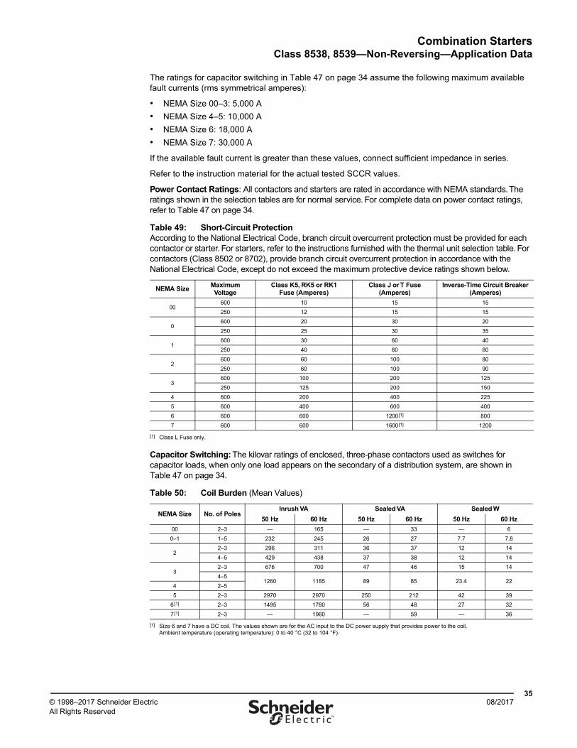
Combination StartersClass 8538, 8539—Non-Reversing—Application Data
3508/2017© 1998–2017 Schneider Electric
All Rights Reserved™
The ratings for capacitor switching in Table 47 on page 34 assume the following maximum available fault currents (rms symmetrical amperes):
• NEMA Size 00–3: 5,000 A
• NEMA Size 4–5: 10,000 A
• NEMA Size 6: 18,000 A
• NEMA Size 7: 30,000 A
If the available fault current is greater than these values, connect sufficient impedance in series.
Refer to the instruction material for the actual tested SCCR values.
Power Contact Ratings: All contactors and starters are rated in accordance with NEMA standards. The ratings shown in the selection tables are for normal service. For complete data on power contact ratings, refer to Table 47 on page 34.
Capacitor Switching: The kilovar ratings of enclosed, three-phase contactors used as switches for capacitor loads, when only one load appears on the secondary of a distribution system, are shown in Table 47 on page 34.
Table 49: Short-Circuit ProtectionAccording to the National Electrical Code, branch circuit overcurrent protection must be provided for each contactor or starter. For starters, refer to the instructions furnished with the thermal unit selection table. For contactors (Class 8502 or 8702), provide branch circuit overcurrent protection in accordance with the National Electrical Code, except do not exceed the maximum protective device ratings shown below.
NEMA SizeMaximumVoltage
Class K5, RK5 or RK1Fuse (Amperes)
Class J or T Fuse (Amperes)
Inverse-Time Circuit Breaker (Amperes)
00600 10 15 15
250 12 15 15
0600 20 30 20
250 25 30 35
1600 30 60 40
250 40 60 60
2600 60 100 80
250 60 100 90
3600 100 200 125
250 125 200 150
4 600 200 400 225
5 600 400 600 400
6 600 600 1200[1]
[1] Class L Fuse only.
800
7 600 600 1600[1] 1200
Table 50: Coil Burden (Mean Values)
NEMA Size No. of PolesInrush VA Sealed VA Sealed W
50 Hz 60 Hz 50 Hz 60 Hz 50 Hz 60 Hz
00 2–3 — 165 — 33 — 6
0–1 1–5 232 245 26 27 7.7 7.8
22–3 296 311 36 37 12 14
4–5 429 438 37 38 12 14
32–3 676 700 47 46 15 14
4–51260 1185 89 85 23.4 22
4 2–5
5 2–3 2970 2970 250 212 42 39
6[1]
[1] Size 6 and 7 have a DC coil. The values shown are for the AC input to the DC power supply that provides power to the coil. Ambient temperature (operating temperature): 0 to 40 °C (32 to 104 °F).
2–3 1495 1780 56 48 27 32
7[1] 2–3 — 1960 — 59 — 36
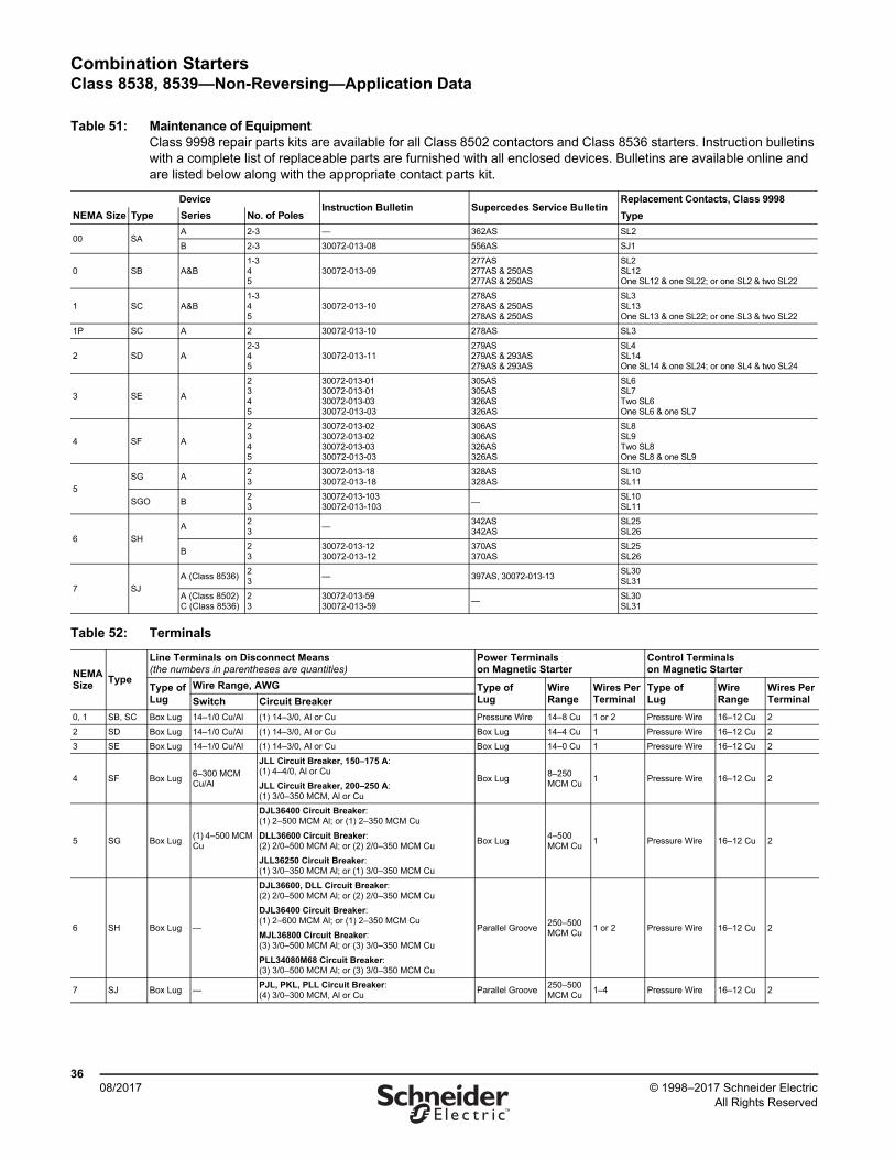
Combination StartersClass 8538, 8539—Non-Reversing—Application Data
3608/2017 © 1998–2017 Schneider Electric
All Rights Reserved™
Table 51: Maintenance of Equipment Class 9998 repair parts kits are available for all Class 8502 contactors and Class 8536 starters. Instruction bulletins with a complete list of replaceable parts are furnished with all enclosed devices. Bulletins are available online and are listed below along with the appropriate contact parts kit.
DeviceInstruction Bulletin Supercedes Service Bulletin
Replacement Contacts, Class 9998
TypeNEMA Size Type Series No. of Poles
00 SAA 2-3 — 362AS SL2
B 2-3 30072-013-08 556AS SJ1
0 SB A&B1-345
30072-013-09277AS277AS & 250AS277AS & 250AS
SL2SL12One SL12 & one SL22; or one SL2 & two SL22
1 SC A&B1-345
30072-013-10278AS278AS & 250AS278AS & 250AS
SL3SL13One SL13 & one SL22; or one SL3 & two SL22
1P SC A 2 30072-013-10 278AS SL3
2 SD A2-345
30072-013-11279AS279AS & 293AS279AS & 293AS
SL4SL14One SL14 & one SL24; or one SL4 & two SL24
3 SE A
2345
30072-013-0130072-013-0130072-013-0330072-013-03
305AS305AS326AS326AS
SL6SL7 Two SL6One SL6 & one SL7
4 SF A
2345
30072-013-0230072-013-0230072-013-0330072-013-03
306AS306AS326AS326AS
SL8SL9Two SL8One SL8 & one SL9
5
SG A23
30072-013-1830072-013-18
328AS328AS
SL10SL11
SGO B23
30072-013-10330072-013-103
—SL10SL11
6 SH
A23
—342AS342AS
SL25SL26
B23
30072-013-1230072-013-12
370AS370AS
SL25SL26
7 SJ
A (Class 8536)23
— 397AS, 30072-013-13SL30SL31
A (Class 8502)C (Class 8536)
23
30072-013-5930072-013-59
—SL30SL31
Table 52: Terminals
NEMASize
Type
Line Terminals on Disconnect Means (the numbers in parentheses are quantities)
Power Terminals on Magnetic Starter
Control Terminals on Magnetic Starter
Type ofLug
Wire Range, AWG Type ofLug
Wire Range
Wires PerTerminal
Type ofLug
Wire Range
Wires PerTerminalSwitch Circuit Breaker
0, 1 SB, SC Box Lug 14–1/0 Cu/Al (1) 14–3/0, Al or Cu Pressure Wire 14–8 Cu 1 or 2 Pressure Wire 16–12 Cu 2
2 SD Box Lug 14–1/0 Cu/Al (1) 14–3/0, Al or Cu Box Lug 14–4 Cu 1 Pressure Wire 16–12 Cu 2
3 SE Box Lug 14–1/0 Cu/Al (1) 14–3/0, Al or Cu Box Lug 14–0 Cu 1 Pressure Wire 16–12 Cu 2
4 SF Box Lug6–300 MCM Cu/Al
JLL Circuit Breaker, 150–175 A: (1) 4–4/0, Al or Cu
JLL Circuit Breaker, 200–250 A:(1) 3/0–350 MCM, Al or Cu
Box Lug8–250 MCM Cu
1 Pressure Wire 16–12 Cu 2
5 SG Box Lug(1) 4–500 MCM Cu
DJL36400 Circuit Breaker: (1) 2–500 MCM Al; or (1) 2–350 MCM Cu
DLL36600 Circuit Breaker:(2) 2/0–500 MCM Al; or (2) 2/0–350 MCM Cu
JLL36250 Circuit Breaker: (1) 3/0–350 MCM Al; or (1) 3/0–350 MCM Cu
Box Lug4–500 MCM Cu
1 Pressure Wire 16–12 Cu 2
6 SH Box Lug —
DJL36600, DLL Circuit Breaker: (2) 2/0–500 MCM Al; or (2) 2/0–350 MCM Cu
DJL36400 Circuit Breaker: (1) 2–600 MCM Al; or (1) 2–350 MCM Cu
MJL36800 Circuit Breaker: (3) 3/0–500 MCM Al; or (3) 3/0–350 MCM Cu
PLL34080M68 Circuit Breaker: (3) 3/0–500 MCM Al; or (3) 3/0–350 MCM Cu
Parallel Groove250–500 MCM Cu
1 or 2 Pressure Wire 16–12 Cu 2
7 SJ Box Lug —PJL, PKL, PLL Circuit Breaker: (4) 3/0–300 MCM, Al or Cu
Parallel Groove250–500 MCM Cu
1–4 Pressure Wire 16–12 Cu 2
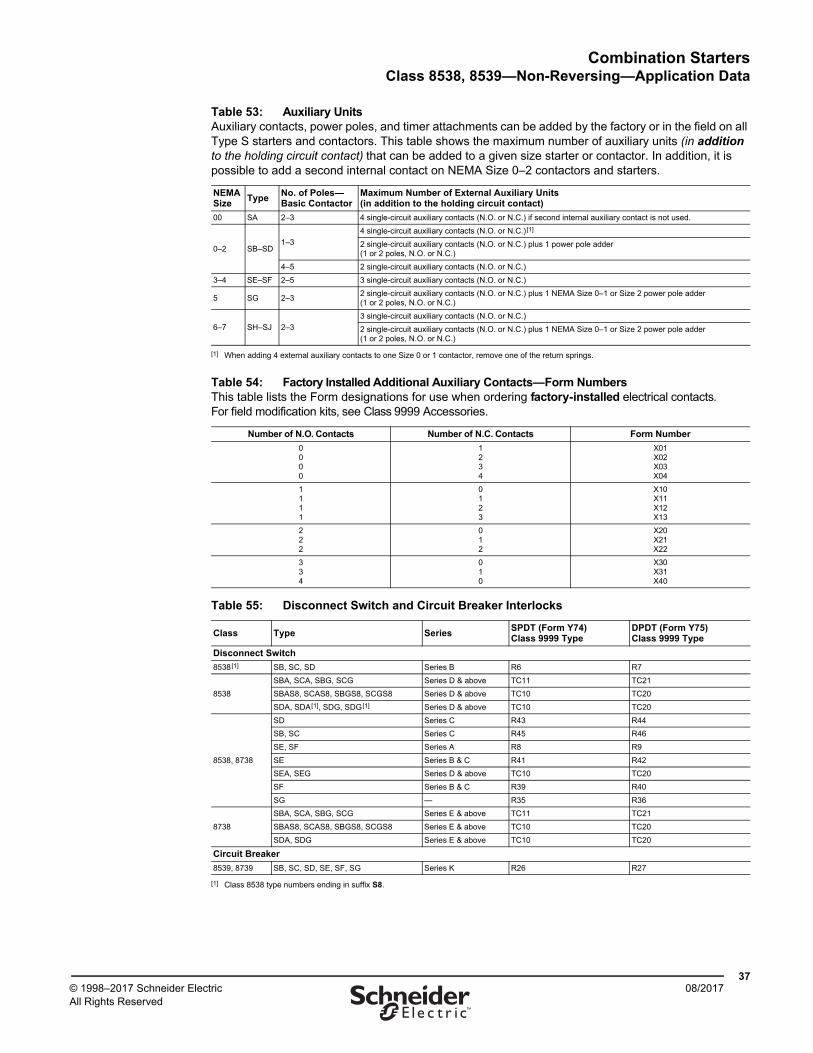
Combination StartersClass 8538, 8539—Non-Reversing—Application Data
3708/2017© 1998–2017 Schneider Electric
All Rights Reserved™
Table 53: Auxiliary UnitsAuxiliary contacts, power poles, and timer attachments can be added by the factory or in the field on all Type S starters and contactors. This table shows the maximum number of auxiliary units (in addition to the holding circuit contact) that can be added to a given size starter or contactor. In addition, it is possible to add a second internal contact on NEMA Size 0–2 contactors and starters.
NEMA Size
TypeNo. of Poles—Basic Contactor
Maximum Number of External Auxiliary Units (in addition to the holding circuit contact)
00 SA 2–3 4 single-circuit auxiliary contacts (N.O. or N.C.) if second internal auxiliary contact is not used.
0–2 SB–SD1–3
4 single-circuit auxiliary contacts (N.O. or N.C.)[1]
[1] When adding 4 external auxiliary contacts to one Size 0 or 1 contactor, remove one of the return springs.
2 single-circuit auxiliary contacts (N.O. or N.C.) plus 1 power pole adder (1 or 2 poles, N.O. or N.C.)
4–5 2 single-circuit auxiliary contacts (N.O. or N.C.)
3–4 SE–SF 2–5 3 single-circuit auxiliary contacts (N.O. or N.C.)
5 SG 2–32 single-circuit auxiliary contacts (N.O. or N.C.) plus 1 NEMA Size 0–1 or Size 2 power pole adder (1 or 2 poles, N.O. or N.C.)
6–7 SH–SJ 2–3
3 single-circuit auxiliary contacts (N.O. or N.C.)
2 single-circuit auxiliary contacts (N.O. or N.C.) plus 1 NEMA Size 0–1 or Size 2 power pole adder (1 or 2 poles, N.O. or N.C.)
Table 54: Factory Installed Additional Auxiliary Contacts—Form NumbersThis table lists the Form designations for use when ordering factory-installed electrical contacts. For field modification kits, see Class 9999 Accessories.
Number of N.O. Contacts Number of N.C. Contacts Form Number
0000
1234
X01X02X03X04
1111
0123
X10X11X12X13
222
012
X20X21X22
334
010
X30X31X40
Table 55: Disconnect Switch and Circuit Breaker Interlocks
Class Type SeriesSPDT (Form Y74)Class 9999 Type
DPDT (Form Y75)Class 9999 Type
Disconnect Switch
8538[1]
[1] Class 8538 type numbers ending in suffix S8.
SB, SC, SD Series B R6 R7
8538
SBA, SCA, SBG, SCG Series D & above TC11 TC21
SBAS8, SCAS8, SBGS8, SCGS8 Series D & above TC10 TC20
SDA, SDA[1], SDG, SDG[1] Series D & above TC10 TC20
8538, 8738
SD Series C R43 R44
SB, SC Series C R45 R46
SE, SF Series A R8 R9
SE Series B & C R41 R42
SEA, SEG Series D & above TC10 TC20
SF Series B & C R39 R40
SG — R35 R36
8738
SBA, SCA, SBG, SCG Series E & above TC11 TC21
SBAS8, SCAS8, SBGS8, SCGS8 Series E & above TC10 TC20
SDA, SDG Series E & above TC10 TC20
Circuit Breaker
8539, 8739 SB, SC, SD, SE, SF, SG Series K R26 R27
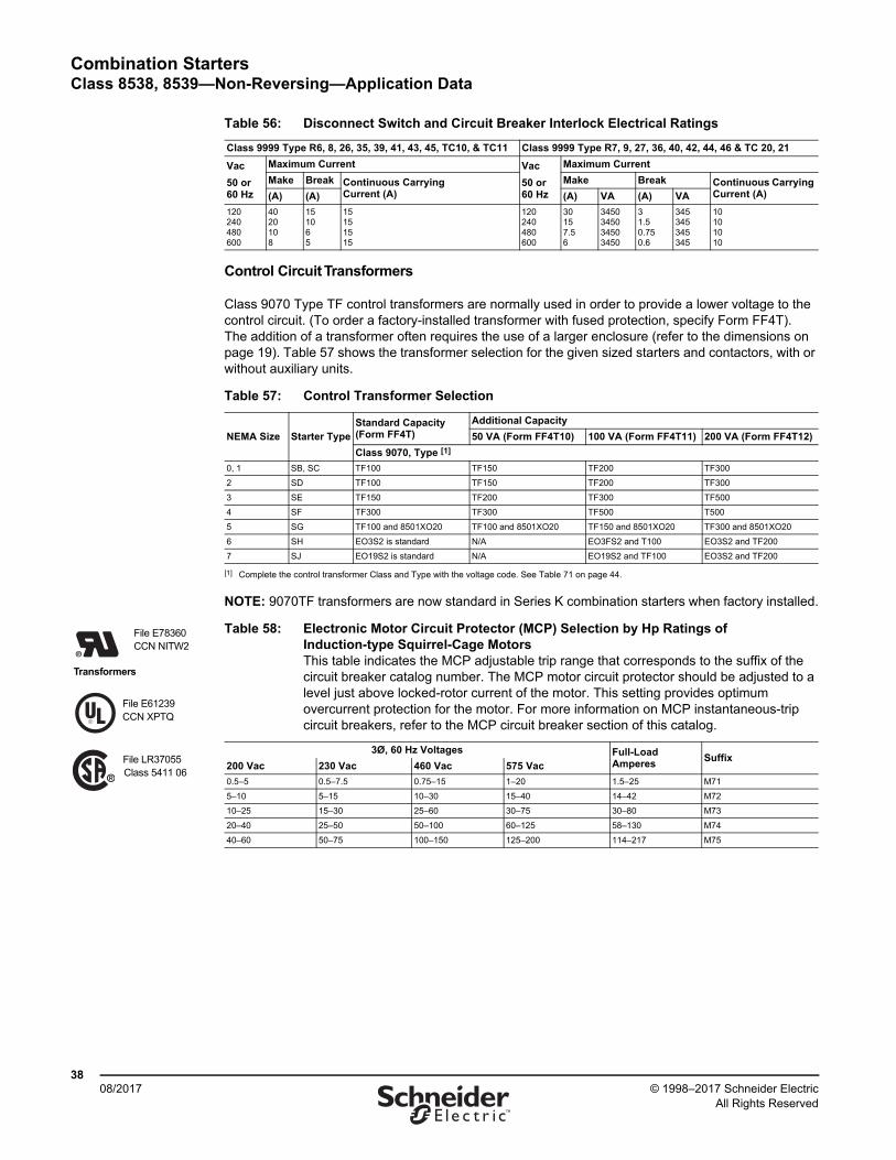
Combination StartersClass 8538, 8539—Non-Reversing—Application Data
3808/2017 © 1998–2017 Schneider Electric
All Rights Reserved™
Control Circuit Transformers
Class 9070 Type TF control transformers are normally used in order to provide a lower voltage to the control circuit. (To order a factory-installed transformer with fused protection, specify Form FF4T). The addition of a transformer often requires the use of a larger enclosure (refer to the dimensions on page 19). Table 57 shows the transformer selection for the given sized starters and contactors, with or without auxiliary units.
NOTE: 9070TF transformers are now standard in Series K combination starters when factory installed.
Table 56: Disconnect Switch and Circuit Breaker Interlock Electrical Ratings
Class 9999 Type R6, 8, 26, 35, 39, 41, 43, 45, TC10, & TC11 Class 9999 Type R7, 9, 27, 36, 40, 42, 44, 46 & TC 20, 21
Vac
50 or 60 Hz
Maximum Current Vac
50 or 60 Hz
Maximum Current
Make Break Continuous Carrying Current (A)
Make Break Continuous Carrying Current (A)(A) (A) (A) VA (A) VA
120240480600
4020108
151065
15151515
120240480600
30157.56
3450345034503450
31.50.750.6
345345345345
10101010
Table 57: Control Transformer Selection
NEMA Size Starter TypeStandard Capacity(Form FF4T)
Additional Capacity
50 VA (Form FF4T10) 100 VA (Form FF4T11) 200 VA (Form FF4T12)
Class 9070, Type [1]
[1] Complete the control transformer Class and Type with the voltage code. See Table 71 on page 44.
0, 1 SB, SC TF100 TF150 TF200 TF300
2 SD TF100 TF150 TF200 TF300
3 SE TF150 TF200 TF300 TF500
4 SF TF300 TF300 TF500 T500
5 SG TF100 and 8501XO20 TF100 and 8501XO20 TF150 and 8501XO20 TF300 and 8501XO20
6 SH EO3S2 is standard N/A EO3FS2 and T100 EO3S2 and TF200
7 SJ EO19S2 is standard N/A EO19S2 and TF100 EO3S2 and TF200
Table 58: Electronic Motor Circuit Protector (MCP) Selection by Hp Ratings of Induction-type Squirrel-Cage MotorsThis table indicates the MCP adjustable trip range that corresponds to the suffix of the circuit breaker catalog number. The MCP motor circuit protector should be adjusted to a level just above locked-rotor current of the motor. This setting provides optimum overcurrent protection for the motor. For more information on MCP instantaneous-trip circuit breakers, refer to the MCP circuit breaker section of this catalog.
3Ø, 60 Hz Voltages Full-LoadAmperes
Suffix200 Vac 230 Vac 460 Vac 575 Vac
0.5–5 0.5–7.5 0.75–15 1–20 1.5–25 M71
5–10 5–15 10–30 15–40 14–42 M72
10–25 15–30 25–60 30–75 30–80 M73
20–40 25–50 50–100 60–125 58–130 M74
40–60 50–75 100–150 125–200 114–217 M75
File E78360CCN NITW2
File E61239CCN XPTQ
File LR37055Class 5411 06
Transformers
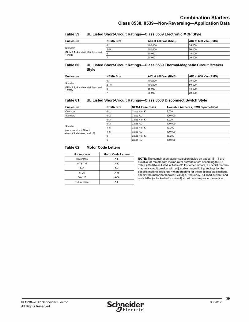
Combination StartersClass 8538, 8539—Non-Reversing—Application Data
3908/2017© 1998–2017 Schneider Electric
All Rights Reserved™
Table 59: UL Listed Short-Circuit Ratings—Class 8539 Electronic MCP Style
Enclosure NEMA Size AIC at 480 Vac (RMS) AIC at 600 Vac (RMS)
Standard
(NEMA 1, 4 and 4X stainless, and 12/3R)
0, 1 100,000 35,000
2–5 100,000 50,000
6 65,000 18,000
7 65,000 30,000
Table 60: UL Listed Short-Circuit Ratings—Class 8539 Thermal-Magnetic Circuit Breaker Style
Enclosure NEMA Size AIC at 480 Vac (RMS) AIC at 600 Vac (RMS)
Standard
(NEMA 1, 4 and 4X stainless, and 12/3R)
0, 1 100,000 35,000
2—5 100,000 50,000
6 65,000 18,000
7 65,000 30,000
Table 61: UL Listed Short-Circuit Ratings—Class 8538 Disconnect Switch Style
Enclosure NEMA Size NEMA Fuse Class Available Amperes, RMS Symmetrical
Oversize 0–2 Class H or K 5,000
Standard 0–2 Class R/J 100,000
Standard
(non-oversize NEMA 1, 4 and 4X stainless, and 12)
0–3 Class H or K 5,000
0–3 Class R/J 100,000
4–5 Class H or K 10,000
4–5 Class R/J 100,000
6 Class H or K 18,000
6 Class R/J 100,000
Table 62: Motor Code Letters
Horsepower Motor Code Letters
NOTE: The combination starter selection tables on pages 15–14 are suitable for motors with locked-rotor current letters according to NEC Table 430-7(b) as listed in Table 62. For other motors, a special thermal-magnetic circuit breaker with adjustable magnetic trip settings for the specific motor is required. When ordering for these special applications, specify the motor horsepower, voltage, frequency, full-load current, and code letter (or locked rotor current) to help ensure proper protection.
0.5 or less A-L
0.75–1.5 A-K
2–3 A-J
5–25 A-H
30–125 A-G
150 or more A-F
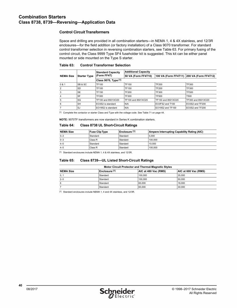
Combination StartersClass 8738, 8739—Reversing—Application Data
4008/2017 © 1998–2017 Schneider Electric
All Rights Reserved™
Control Circuit Transformers
Space and drilling are provided in all combination starters—in NEMA 1, 4 & 4X stainless, and 12/3R enclosures—for the field addition (or factory installation) of a Class 9070 transformer. For standard control transformer selection in reversing combination starters, see Table 63. For primary fusing of the control circuit, the Class 9999 Type SF4 fuseholder kit is suggested. This kit can be either panel mounted or side mounted on the Type S starter.
NOTE: 9070TF transformers are now standard in Series K combination starters.
Table 63: Control Transformer Selection
NEMA Size Starter TypeStandard Capacity(Form FF4T)
Additional Capacity
50 VA (Form FF4T10) 100 VA (Form FF4T11) 200 VA (Form FF4T12)
Class 9070, Type [1]
[1] Complete the contactor or starter Class and Type with the voltage code. See Table 71 on page 44.
0 & 1 SB & SC TF100 TF150 TF200 TF300
2 SD TF100 TF150 TF200 TF300
3 SE TF150 TF200 TF300 TF500
4 SF TF300 TF300 TF500 T500
5 SG TF100 and 8501XO20 TF100 and 8501XO20 TF150 and 8501XO20 TF300 and 8501XO20
6 SH EO3S2 is standard N/A EO3FS2 and T100 EO3S2 and TF200
7 SJ EO19S2 is standard N/A EO19S2 and TF100 EO3S2 and TF200
Table 64: Class 8738 UL Short-Circuit Ratings
NEMA Size Fuse Clip Type Enclosure [1]
[1] Standard enclosures include NEMA 1, 4 & 4X stainless, and 12/3R.
Ampere Interrupting Capability Rating (AIC)
0–3 Standard Standard 5,000
0–3 Class R Standard 100,000
4–5 Standard Standard 10,000
4–5 Class R Standard 100,000
Table 65: Class 8739—UL Listed Short-Circuit Ratings
Motor Circuit Protector and Thermal-Magnetic Styles
NEMA Size Enclosure [1]
[1] Standard enclosures include NEMA 1, 4 and 4X stainless, and 12/3R.
AIC at 480 Vac (RMS) AIC at 600 Vac (RMS)
0, 1 Standard 100,000 35,000
2–5 Standard 100,000 50,000
6 Standard 65,000 18,000
7 Standard 65,000 30,000
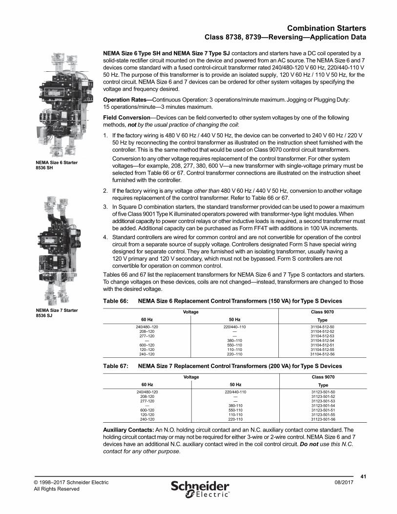
Combination StartersClass 8738, 8739—Reversing—Application Data
4108/2017© 1998–2017 Schneider Electric
All Rights Reserved™
NEMA Size 6 Type SH and NEMA Size 7 Type SJ contactors and starters have a DC coil operated by a solid-state rectifier circuit mounted on the device and powered from an AC source. The NEMA Size 6 and 7 devices come standard with a fused control-circuit transformer rated 240/480-120 V 60 Hz, 220/440-110 V 50 Hz. The purpose of this transformer is to provide an isolated supply, 120 V 60 Hz / 110 V 50 Hz, for the control circuit. NEMA Size 6 and 7 devices can be ordered for other system voltages by specifying the voltage and frequency desired.
Operation Rates—Continuous Operation: 3 operations/minute maximum. Jogging or Plugging Duty: 15 operations/minute—3 minutes maximum.
Field Conversion—Devices can be field converted to other system voltages by one of the following methods, not by the usual practice of changing the coil:
1. If the factory wiring is 480 V 60 Hz / 440 V 50 Hz, the device can be converted to 240 V 60 Hz / 220 V 50 Hz by reconnecting the control transformer as illustrated on the instruction sheet furnished with the controller. This is the same method that would be used on Class 9070 control circuit transformers.
Conversion to any other voltage requires replacement of the control transformer. For other system voltages—for example, 208, 277, 380, 600 V—a new transformer with single-voltage primary must be selected from Table 66 or 67. Control transformer connections are illustrated on the instruction sheet furnished with the controller.
2. If the factory wiring is any voltage other than 480 V 60 Hz / 440 V 50 Hz, conversion to another voltage requires replacement of the control transformer. Refer to Table 66 or 67.
3. In Square D combination starters, the standard transformer provided can be used to power a maximum of five Class 9001 Type K illuminated operators powered with transformer-type light modules. When additional capacity to power control relays or other inductive loads is required, a second transformer must be added. Additional capacity can be purchased as Form FF4T with additions in 100 VA increments.
4. Standard controllers are wired for common control and are not convertible for operation of the control circuit from a separate source of supply voltage. Controllers designated Form S have special wiring designed for separate control. They are furnished with an isolating transformer, usually having a 120 V primary and 120 V secondary, which must not be bypassed. Form S controllers are not convertible for operation on common control.
Tables 66 and 67 list the replacement transformers for NEMA Size 6 and 7 Type S contactors and starters. To change voltages on these devices, coils are not changed—instead, transformers are changed to those with the desired voltage.
Auxiliary Contacts: An N.O. holding circuit contact and an N.C. auxiliary contact come standard. The holding circuit contact may or may not be required for either 3-wire or 2-wire control. NEMA Size 6 and 7 devices have an additional N.C. auxiliary contact wired in the coil control circuit. Do not use this N.C. contact for any other purpose.
Table 66: NEMA Size 6 Replacement Control Transformers (150 VA) for Type S Devices
Voltage Class 9070
Type60 Hz 50 Hz
240/480–120208–120277–120
—600–120120–120240–120
220/440–110——
380–110550–110110–110220–110
31104-512-5031104-512-5231104-512-5331104-512-5431104-512-5131104-512-5531104-512-56
Table 67: NEMA Size 7 Replacement Control Transformers (200 VA) for Type S Devices
Voltage Class 9070
Type60 Hz 50 Hz
240/480-120208-120277-120
—600-120120-120240-120
220/440-110——
380-110550-110110-110220-110
31123-501-5031123-501-5231123-501-5331123-501-5431123-501-5131123-501-5531123-501-56
NEMA Size 6 Starter8536 SH
NEMA Size 7 Starter8536 SJ
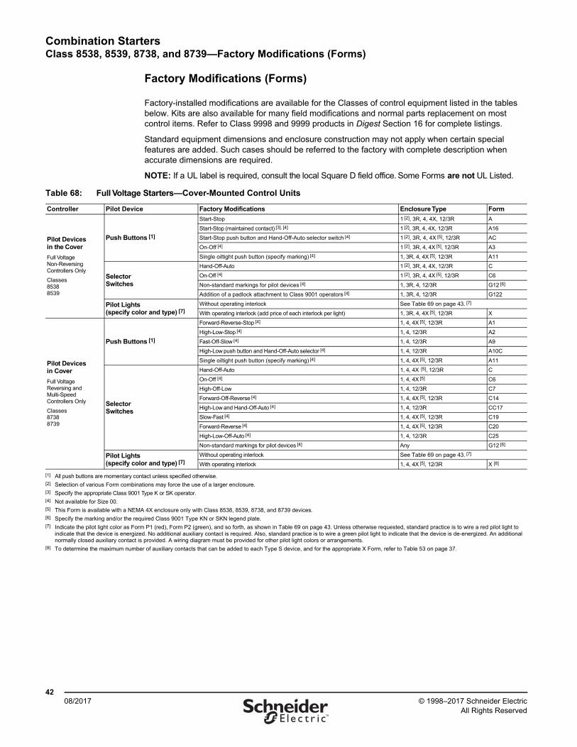
Combination StartersClass 8538, 8539, 8738, and 8739—Factory Modifications (Forms)
4208/2017 © 1998–2017 Schneider Electric
All Rights Reserved™
Factory Modifications (Forms)
Factory-installed modifications are available for the Classes of control equipment listed in the tables below. Kits are also available for many field modifications and normal parts replacement on most control items. Refer to Class 9998 and 9999 products in Digest Section 16 for complete listings.
Standard equipment dimensions and enclosure construction may not apply when certain special features are added. Such cases should be referred to the factory with complete description when accurate dimensions are required.
NOTE: If a UL label is required, consult the local Square D field office. Some Forms are not UL Listed.
Table 68: Full Voltage Starters—Cover-Mounted Control Units
Controller Pilot Device Factory Modifications Enclosure Type Form
Pilot Devices in the Cover
Full Voltage Non-Reversing Controllers Only
Classes85388539
Push Buttons [1]
Start-Stop 1 [2], 3R, 4, 4X, 12/3R A
Start-Stop (maintained contact) [3], [4] 1 [2], 3R, 4, 4X, 12/3R A16
Start-Stop push button and Hand-Off-Auto selector switch [4] 1 [2], 3R, 4, 4X [5], 12/3R AC
On-Off [4] 1 [2], 3R, 4, 4X [5], 12/3R A3
Single oiltight push button (specify marking) [4] 1, 3R, 4, 4X [5], 12/3R A11
Selector Switches
Hand-Off-Auto 1 [2], 3R, 4, 4X, 12/3R C
On-Off [4] 1 [2], 3R, 4, 4X [5], 12/3R C6
Non-standard markings for pilot devices [4] 1, 3R, 4, 12/3R G12 [6]
Addition of a padlock attachment to Class 9001 operators [4] 1, 3R, 4, 12/3R G122
Pilot Lights (specify color and type) [7]
Without operating interlock See Table 69 on page 43. [7]
With operating interlock (add price of each interlock per light) 1, 3R, 4, 4X [5], 12/3R X
Pilot Devices in Cover
Full Voltage Reversing and Multi-Speed Controllers Only
Classes87388739
Push Buttons [1]
Forward-Reverse-Stop [4] 1, 4, 4X [5], 12/3R A1
High-Low-Stop [4] 1, 4, 12/3R A2
Fast-Off-Slow [4] 1, 4, 12/3R A9
High-Low push button and Hand-Off-Auto selector [4] 1, 4, 12/3R A10C
Single oiltight push button (specify marking) [4] 1, 4, 4X [5], 12/3R A11
Selector Switches
Hand-Off-Auto 1, 4, 4X [5], 12/3R C
On-Off [4] 1, 4, 4X [5] C6
High-Off-Low 1, 4, 12/3R C7
Forward-Off-Reverse [4] 1, 4, 4X [5], 12/3R C14
High-Low and Hand-Off-Auto [4] 1, 4, 12/3R CC17
Slow-Fast [4] 1, 4, 4X [5], 12/3R C19
Forward-Reverse [4] 1, 4, 4X [5], 12/3R C20
High-Low-Off-Auto [4] 1, 4, 12/3R C25
Non-standard markings for pilot devices [4] Any G12 [6]
Pilot Lights (specify color and type) [7]
Without operating interlock See Table 69 on page 43. [7]
With operating interlock 1, 4, 4X [5], 12/3R X [8]
[1] All push buttons are momentary contact unless specified otherwise.[2] Selection of various Form combinations may force the use of a larger enclosure. [3] Specify the appropriate Class 9001 Type K or SK operator.[4] Not available for Size 00.[5] This Form is available with a NEMA 4X enclosure only with Class 8538, 8539, 8738, and 8739 devices.[6] Specify the marking and/or the required Class 9001 Type KN or SKN legend plate.[7] Indicate the pilot light color as Form P1 (red), Form P2 (green), and so forth, as shown in Table 69 on page 43. Unless otherwise requested, standard practice is to wire a red pilot light to
indicate that the device is energized. No additional auxiliary contact is required. Also, standard practice is to wire a green pilot light to indicate that the device is de-energized. An additional normally closed auxiliary contact is provided. A wiring diagram must be provided for other pilot light colors or arrangements.
[8] To determine the maximum number of auxiliary contacts that can be added to each Type S device, and for the appropriate X Form, refer to Table 53 on page 37.
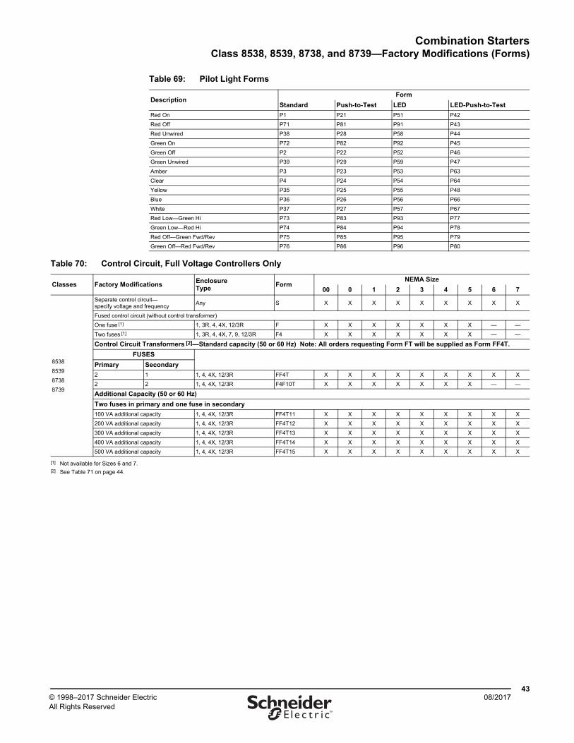
Combination StartersClass 8538, 8539, 8738, and 8739—Factory Modifications (Forms)
4308/2017© 1998–2017 Schneider Electric
All Rights Reserved™
Table 69: Pilot Light Forms
DescriptionForm
Standard Push-to-Test LED LED-Push-to-Test
Red On P1 P21 P51 P42
Red Off P71 P81 P91 P43
Red Unwired P38 P28 P58 P44
Green On P72 P82 P92 P45
Green Off P2 P22 P52 P46
Green Unwired P39 P29 P59 P47
Amber P3 P23 P53 P63
Clear P4 P24 P54 P64
Yellow P35 P25 P55 P48
Blue P36 P26 P56 P66
White P37 P27 P57 P67
Red Low—Green Hi P73 P83 P93 P77
Green Low—Red Hi P74 P84 P94 P78
Red Off—Green Fwd/Rev P75 P85 P95 P79
Green Off—Red Fwd/Rev P76 P86 P96 P80
Table 70: Control Circuit, Full Voltage Controllers Only
Classes Factory ModificationsEnclosureType
FormNEMA Size
00 0 1 2 3 4 5 6 7
8538
8539
8738
8739
Separate control circuit—specify voltage and frequency
Any S X X X X X X X X X
Fused control circuit (without control transformer)
One fuse [1] 1, 3R, 4, 4X, 12/3R F X X X X X X X — —
Two fuses [1] 1, 3R, 4, 4X, 7, 9, 12/3R F4 X X X X X X X — —
Control Circuit Transformers [2]—Standard capacity (50 or 60 Hz) Note: All orders requesting Form FT will be supplied as Form FF4T.
FUSES
Primary Secondary
2 1 1, 4, 4X, 12/3R FF4T X X X X X X X X X
2 2 1, 4, 4X, 12/3R F4F10T X X X X X X X — —
Additional Capacity (50 or 60 Hz)
Two fuses in primary and one fuse in secondary
100 VA additional capacity 1, 4, 4X, 12/3R FF4T11 X X X X X X X X X
200 VA additional capacity 1, 4, 4X, 12/3R FF4T12 X X X X X X X X X
300 VA additional capacity 1, 4, 4X, 12/3R FF4T13 X X X X X X X X X
400 VA additional capacity 1, 4, 4X, 12/3R FF4T14 X X X X X X X X X
500 VA additional capacity 1, 4, 4X, 12/3R FF4T15 X X X X X X X X X
[1] Not available for Sizes 6 and 7.[2] See Table 71 on page 44.
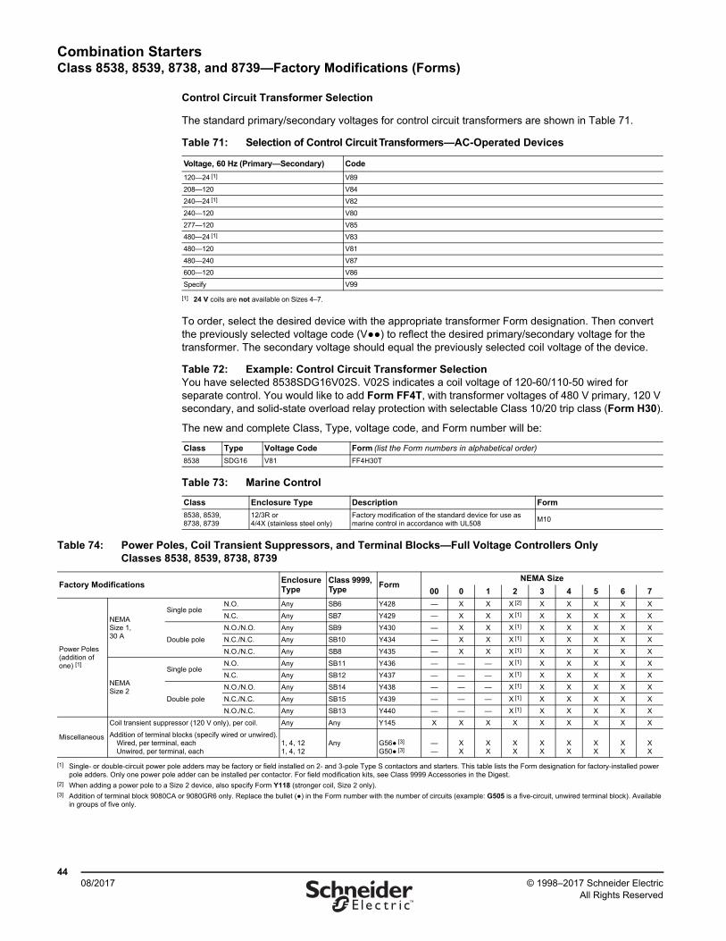
Combination StartersClass 8538, 8539, 8738, and 8739—Factory Modifications (Forms)
4408/2017 © 1998–2017 Schneider Electric
All Rights Reserved™
Control Circuit Transformer Selection
The standard primary/secondary voltages for control circuit transformers are shown in Table 71.
To order, select the desired device with the appropriate transformer Form designation. Then convert the previously selected voltage code (V●●) to reflect the desired primary/secondary voltage for the transformer. The secondary voltage should equal the previously selected coil voltage of the device.
Table 71: Selection of Control Circuit Transformers—AC-Operated Devices
Voltage, 60 Hz (Primary—Secondary) Code
120—24 [1]
[1] 24 V coils are not available on Sizes 4–7.
V89
208—120 V84
240—24 [1] V82
240—120 V80
277—120 V85
480—24 [1] V83
480—120 V81
480—240 V87
600—120 V86
Specify V99
Table 72: Example: Control Circuit Transformer SelectionYou have selected 8538SDG16V02S. V02S indicates a coil voltage of 120-60/110-50 wired for separate control. You would like to add Form FF4T, with transformer voltages of 480 V primary, 120 V secondary, and solid-state overload relay protection with selectable Class 10/20 trip class (Form H30).
The new and complete Class, Type, voltage code, and Form number will be:
Class Type Voltage Code Form (list the Form numbers in alphabetical order)
8538 SDG16 V81 FF4H30T
Table 73: Marine Control
Class Enclosure Type Description Form
8538, 8539, 8738, 8739
12/3R or 4/4X (stainless steel only)
Factory modification of the standard device for use as marine control in accordance with UL508
M10
Table 74: Power Poles, Coil Transient Suppressors, and Terminal Blocks—Full Voltage Controllers Only Classes 8538, 8539, 8738, 8739
Factory ModificationsEnclosureType
Class 9999, Type
FormNEMA Size
00 0 1 2 3 4 5 6 7
Power Poles (addition of one) [1]
NEMA Size 1, 30 A
Single poleN.O. Any SB6 Y428 — X X X [2] X X X X X
N.C. Any SB7 Y429 — X X X [1] X X X X X
Double pole
N.O./N.O. Any SB9 Y430 — X X X [1] X X X X X
N.C./N.C. Any SB10 Y434 — X X X [1] X X X X X
N.O./N.C. Any SB8 Y435 — X X X [1] X X X X X
NEMA Size 2
Single poleN.O. Any SB11 Y436 — — — X [1] X X X X X
N.C. Any SB12 Y437 — — — X [1] X X X X X
Double pole
N.O./N.O. Any SB14 Y438 — — — X [1] X X X X X
N.C./N.C. Any SB15 Y439 — — — X [1] X X X X X
N.O./N.C. Any SB13 Y440 — — — X [1] X X X X X
Miscellaneous
Coil transient suppressor (120 V only), per coil.
Addition of terminal blocks (specify wired or unwired).Wired, per terminal, eachUnwired, per terminal, each
Any Any Y145 X X X X X X X X X
1, 4, 121, 4, 12
Any G56● [3]
G50● [3]——
XX
XX
X X
XX
XX
XX
XX
XX
[1] Single- or double-circuit power pole adders may be factory or field installed on 2- and 3-pole Type S contactors and starters. This table lists the Form designation for factory-installed power pole adders. Only one power pole adder can be installed per contactor. For field modification kits, see Class 9999 Accessories in the Digest.
[2] When adding a power pole to a Size 2 device, also specify Form Y118 (stronger coil, Size 2 only).[3] Addition of terminal block 9080CA or 9080GR6 only. Replace the bullet (●) in the Form number with the number of circuits (example: G505 is a five-circuit, unwired terminal block). Available
in groups of five only.
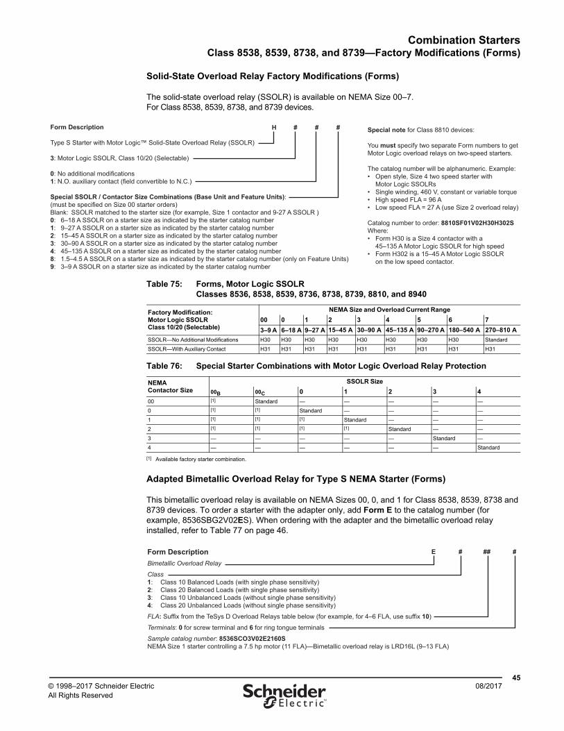
Combination StartersClass 8538, 8539, 8738, and 8739—Factory Modifications (Forms)
4508/2017© 1998–2017 Schneider Electric
All Rights Reserved™
Solid-State Overload Relay Factory Modifications (Forms)
The solid-state overload relay (SSOLR) is available on NEMA Size 00–7.For Class 8538, 8539, 8738, and 8739 devices.
Adapted Bimetallic Overload Relay for Type S NEMA Starter (Forms)
This bimetallic overload relay is available on NEMA Sizes 00, 0, and 1 for Class 8538, 8539, 8738 and 8739 devices. To order a starter with the adapter only, add Form E to the catalog number (for example, 8536SBG2V02ES). When ordering with the adapter and the bimetallic overload relay installed, refer to Table 77 on page 46.
Form Description
Type S Starter with Motor Logic™ Solid-State Overload Relay (SSOLR)
3: Motor Logic SSOLR, Class 10/20 (Selectable)
0: No additional modifications1: N.O. auxiliary contact (field convertible to N.C.)
Special SSOLR / Contactor Size Combinations (Base Unit and Feature Units):(must be specified on Size 00 starter orders)Blank: SSOLR matched to the starter size (for example, Size 1 contactor and 9-27 A SSOLR )0: 6–18 A SSOLR on a starter size as indicated by the starter catalog number1: 9–27 A SSOLR on a starter size as indicated by the starter catalog number2: 15–45 A SSOLR on a starter size as indicated by the starter catalog number3: 30–90 A SSOLR on a starter size as indicated by the starter catalog number4: 45–135 A SSOLR on a starter size as indicated by the starter catalog number8: 1.5–4.5 A SSOLR on a starter size as indicated by the starter catalog number (only on Feature Units)9: 3–9 A SSOLR on a starter size as indicated by the starter catalog number
H # # # Special note for Class 8810 devices:
You must specify two separate Form numbers to get Motor Logic overload relays on two-speed starters.
The catalog number will be alphanumeric. Example: • Open style, Size 4 two speed starter with Motor Logic SSOLRs • Single winding, 460 V, constant or variable torque• High speed FLA = 96 A• Low speed FLA = 27 A (use Size 2 overload relay)
Catalog number to order: 8810SF01V02H30H302SWhere: • Form H30 is a Size 4 contactor with a 45–135 A Motor Logic SSOLR for high speed • Form H302 is a 15–45 A Motor Logic SSOLR on the low speed contactor.
Table 75: Forms, Motor Logic SSOLR Classes 8536, 8538, 8539, 8736, 8738, 8739, 8810, and 8940
Factory Modification: Motor Logic SSOLR Class 10/20 (Selectable)
NEMA Size and Overload Current Range
00 0 1 2 3 4 5 6 7
3–9 A 6–18 A 9–27 A 15–45 A 30–90 A 45–135 A 90–270 A 180–540 A 270–810 A
SSOLR—No Additional Modifications H30 H30 H30 H30 H30 H30 H30 H30 Standard
SSOLR—With Auxiliary Contact H31 H31 H31 H31 H31 H31 H31 H31 H31
Table 76: Special Starter Combinations with Motor Logic Overload Relay Protection
NEMA Contactor Size
SSOLR Size
00B 00C 0 1 2 3 4
00 [1]
[1] Available factory starter combination.
Standard — — — — —
0 [1] [1] Standard — — — —
1 [1] [1] [1] Standard — — —
2 [1] [1] [1] [1] Standard — —
3 — — — — — Standard —
4 — — — — — — Standard
Form DescriptionBimetallic Overload Relay
Class1: Class 10 Balanced Loads (with single phase sensitivity)2: Class 20 Balanced Loads (with single phase sensitivity)3: Class 10 Unbalanced Loads (without single phase sensitivity)4: Class 20 Unbalanced Loads (without single phase sensitivity)
FLA: Suffix from the TeSys D Overload Relays table below (for example, for 4–6 FLA, use suffix 10)
Terminals: 0 for screw terminal and 6 for ring tongue terminals
Sample catalog number: 8536SCO3V02E2160SNEMA Size 1 starter controlling a 7.5 hp motor (11 FLA)—Bimetallic overload relay is LRD16L (9–13 FLA)
E # ## #
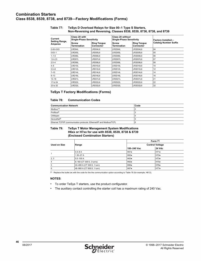
Combination StartersClass 8538, 8539, 8738, and 8739—Factory Modifications (Forms)
4608/2017 © 1998–2017 Schneider Electric
All Rights Reserved™
TeSys T Factory Modifications (Forms)
NOTES:
• To order TeSys T starters, use the product configurator.
• The auxiliary contact controlling the starter coil has a maximum rating of 240 Vac.
Table 77: TeSys D Overload Relays for Size 00–1 Type S Starters, Non-Reversing and Reversing, Classes 8538, 8539, 8736, 8738, and 8739
Current Setting Range, Amperes
Class 20 with Single-Phase Sensitivity
Class 20 without Single-Phase Sensitivity Factory Installed—
Catalog Number SuffixScrew Termination
Ring Tongue Connector
Screw Termination
Ring Tongue Connector
0.40–0.63 LRD04L LRD04L6 LR3D04L LR3D04L6 04
0.63–1 LRD05L LRD05L6 LR3D05L LR3D05L6 05
1–1.6 LRD06L LRD06L6 LR3D06L LR3D06L6 06
1.6–2.5 LRD07L LRD07L6 LR3D07L LR3D07L6 07
2.5–4 LRD08L LRD08L6 LR3D08L LR3D08L6 08
4–6 LRD10L LRD10L6 LR3D10L LR3D10L6 10
5.5–8 LRD12L LRD12L6 LR3D12L LR3D12L6 12
7–10 LRD14L LRD14L6 LR3D14L LR3D14L6 14
9–13 LRD16L LRD16L6 LR3D16L LR3D16L6 16
12–18 LRD21L LRD21L6 LR3D21L LR3D21L6 21
17 to 24 LRD22L LRD22L6 LR3D22L LR3D22L6 22
23 to 32 LRD32L LRD32L6 LR3D32L LR3D32L6 32
Table 78: Communication Codes
Communication Network Code
Modbus™ 2
Profibus® 3
CANopen 4
DeviceNet® 5
Ethernet TCP/IP (communication protocols: Ethernet/IP and Modbus/TCP) 6
Table 79: TeSys T Motor Management System ModificationsH6xx or H7xx for use with 8538, 8539, 8738 & 8739 (Enclosed Combination Starters)
Used on Size Range
Form [1]
[1] Replace the bullet (●) with the code for the the communication option according to Table 78 (for example, H612).
Control Voltage
100–240 Vac 24 Vdc
10.4–8 A H61● H71●
1.35–27 A H62● H72●
2, 3 5.0–100 A H63● H73●
4 8–160 (CT 300:5, 3 turns) H65● H75●
5 24–480 A (CT 300:5, 1 turn) H66● H76●
6 48–960 A (CT 600:5, 1 turn) H67● H77●
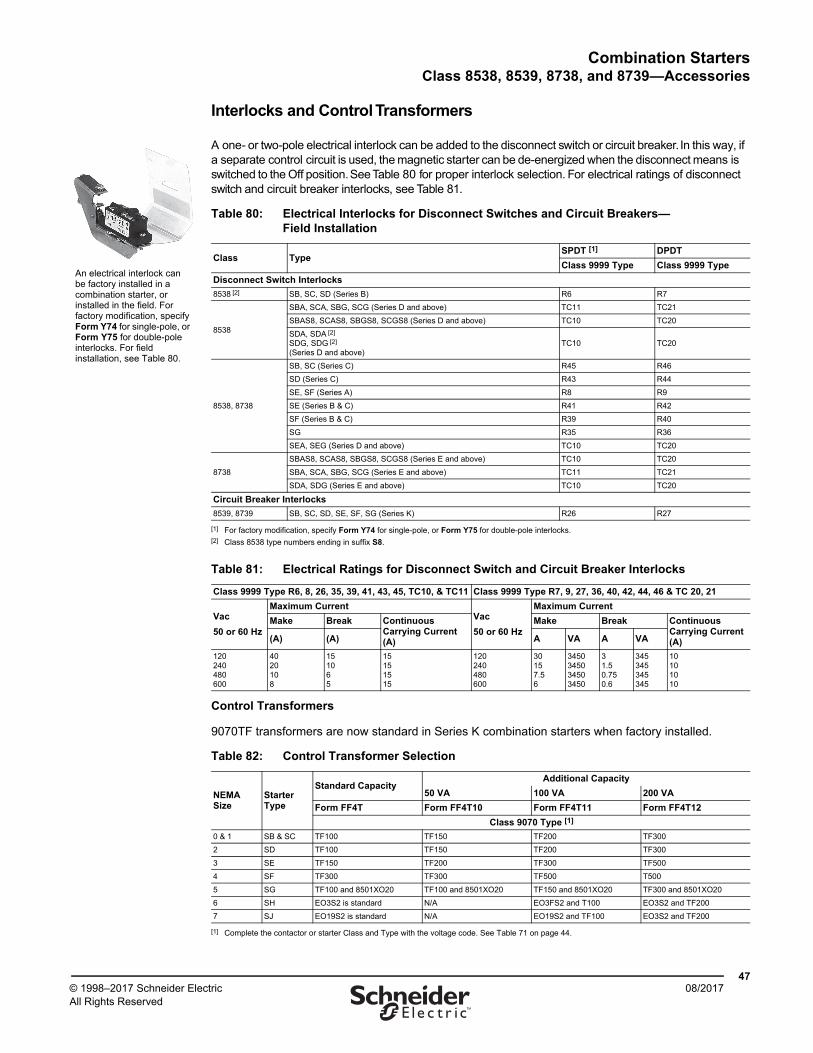
Combination StartersClass 8538, 8539, 8738, and 8739—Accessories
4708/2017© 1998–2017 Schneider Electric
All Rights Reserved™
Interlocks and Control Transformers
A one- or two-pole electrical interlock can be added to the disconnect switch or circuit breaker. In this way, if a separate control circuit is used, the magnetic starter can be de-energized when the disconnect means is switched to the Off position. See Table 80 for proper interlock selection. For electrical ratings of disconnect switch and circuit breaker interlocks, see Table 81.
Control Transformers
9070TF transformers are now standard in Series K combination starters when factory installed.
Table 80: Electrical Interlocks for Disconnect Switches and Circuit Breakers—Field Installation
Class TypeSPDT [1]
[1] For factory modification, specify Form Y74 for single-pole, or Form Y75 for double-pole interlocks.
DPDT
Class 9999 Type Class 9999 Type
Disconnect Switch Interlocks
8538 [2]
[2] Class 8538 type numbers ending in suffix S8.
SB, SC, SD (Series B) R6 R7
8538
SBA, SCA, SBG, SCG (Series D and above) TC11 TC21
SBAS8, SCAS8, SBGS8, SCGS8 (Series D and above) TC10 TC20
SDA, SDA [2]
SDG, SDG [2]
(Series D and above)TC10 TC20
8538, 8738
SB, SC (Series C) R45 R46
SD (Series C) R43 R44
SE, SF (Series A) R8 R9
SE (Series B & C) R41 R42
SF (Series B & C) R39 R40
SG R35 R36
SEA, SEG (Series D and above) TC10 TC20
8738
SBAS8, SCAS8, SBGS8, SCGS8 (Series E and above) TC10 TC20
SBA, SCA, SBG, SCG (Series E and above) TC11 TC21
SDA, SDG (Series E and above) TC10 TC20
Circuit Breaker Interlocks
8539, 8739 SB, SC, SD, SE, SF, SG (Series K) R26 R27
Table 81: Electrical Ratings for Disconnect Switch and Circuit Breaker Interlocks
Class 9999 Type R6, 8, 26, 35, 39, 41, 43, 45, TC10, & TC11 Class 9999 Type R7, 9, 27, 36, 40, 42, 44, 46 & TC 20, 21
Vac
50 or 60 Hz
Maximum CurrentVac
50 or 60 Hz
Maximum Current
Make Break Continuous Carrying Current (A)
Make Break Continuous Carrying Current (A)(A) (A) A VA A VA
120240480600
4020108
151065
15151515
120240480600
30157.56
3450345034503450
31.50.750.6
345345345345
10101010
Table 82: Control Transformer Selection
NEMA Size
Starter Type
Standard CapacityAdditional Capacity
50 VA 100 VA 200 VA
Form FF4T Form FF4T10 Form FF4T11 Form FF4T12
Class 9070 Type [1]
[1] Complete the contactor or starter Class and Type with the voltage code. See Table 71 on page 44.
0 & 1 SB & SC TF100 TF150 TF200 TF300
2 SD TF100 TF150 TF200 TF300
3 SE TF150 TF200 TF300 TF500
4 SF TF300 TF300 TF500 T500
5 SG TF100 and 8501XO20 TF100 and 8501XO20 TF150 and 8501XO20 TF300 and 8501XO20
6 SH EO3S2 is standard N/A EO3FS2 and T100 EO3S2 and TF200
7 SJ EO19S2 is standard N/A EO19S2 and TF100 EO3S2 and TF200
An electrical interlock can be factory installed in a combination starter, or installed in the field. For factory modification, specify Form Y74 for single-pole, or Form Y75 for double-pole interlocks. For field installation, see Table 80.

Schneider Electric USA, Inc.800 Federal StreetAndover, MA 01810 USA888-778-2733www.schneider-electric.us
Schneider Electric, Square D, Modbus, Motor Logic, and TeSys are trademarks and the property of Schneider Electric SE, its subsidiaries, and affiliated companies. All other trademarks are the property of their respective owners.
8538CT9701R08/17 Replaces 8538CT9701 01/1998© 1998–2017 Schneider Electric All Rights Reserved
08/2017
Combination StartersClass 8538, 8539, 8738, and 8739—Accessories
Internal Auxiliary Switch—Circuit breakers can be furnished with a factory installed auxiliary switch for remote indication of an open/tripped or closed circuit breaker. One auxiliary switch (Form Y741) or two auxiliary switches (Form Y751) can be furnished. The switches come with normally open and normally closed circuits with a common connection. Contacts must be used on the same polarity and are rated 15 A at 240 Vac. The auxiliary switches are located internally and come with 19–20 in. leads.
Alarm Switch—The alarm switch is used to actuate bell alarms and warning lights. It operates only when the circuit breaker is tripped. The alarm switch is factory installed only (Form Y742) and consists of a single-pole, single-throw switch, which is normally open except when the circuit breaker is tripped. The contacts are rated 4 A at 240 Vac. This switch is located in the circuit breaker and comes with 19–20 in. leads.
Transformer Selection—In all disconnect switch and circuit breaker combination starters in enclosures (NEMA 1, 4 & 4X stainless and polyester, and 12/3R), space and drilling are available for the field addition or factory installation of a Class 9070 control circuit transformer and Class 9999 Type SFR4 fuse holder. This kit can be either panel mounted or side mounted on the Type S starter. For standard control transformer selection in combination starters, see Table 82 on page 47. For secondary fuse holder, order 9080PF1.
Fuse Block Mounting Brackets—The standard capacity transformer, Class 9070 Type TF100, for the Size 0 and 1 starters mounts to the right of the magnetic starter.
Codes and Standards—Most combination starters and Forms are UL Listed in file E152395, Category NKJH, and CSA approved in File CR 584.