
College of Engineering Mechanical Engineering Department ...
137
Palestine Polytechnic University College of Engineering Mechanical Engineering Department of Refrigeration and Air-Conditioning Graduation Project Design and Documentation The Mechanical System of Two Hundred Fifty Bed at Halhoul Hospital By Mohammad Darawish Nidal Namoura Supervisor: Dr. Ishaq Sider Palestine 2017
Transcript of College of Engineering Mechanical Engineering Department ...

Palestine Polytechnic University
College of Engineering
Mechanical Engineering
Department of Refrigeration andAir-Conditioning
Graduation Project
Design and Documentation The Mechanical System
of Two Hundred Fifty Bed
at Halhoul Hospital
By
Mohammad Darawish
Nidal Namoura
Supervisor: Dr. Ishaq Sider
Palestine
2017

Palestine Polytechnic University
College of Engineering
Mechanical Engineering Department
Hebron - Palestine
Graduation Project Evaluation
According to the project supervisor and according to the agreement of the
Testing Committee Members, this project is submitted to the Department of
Mechanical Engineering at College of Engineering and Technology in partial
fulfillments of the requirements of (B.SC) degree.
Supervisor Signature
. . . . . . . . . . . . . . . . . . . . . . . . . . . . . . . . . ..
Committee signature
. . . . . . . . . . . . . . . . . . . . . . . . . . . . . . . . . . . . . . . . . . . . . . . . . . .
. . . . . . . . . . . . . . . . . . . . . . . . . . . .
Department Headmaster Signature
. . . . . . . . . .. . . . . . . . . . . . . . .
i

Dedication
To The Souls of Our Ancestors
Who Left With Rivers Of Benevolence
To Our Parents Those Who Were Mentors, Teachers and Friends
Who Were Guidance with Their Endless Giving
To Our Teachers
Who Were Candles, Lighting Our Path to Excellence
To Our Beloved University
Where Our Hearts Will Remain
To All Those
We Promis
The Promise of the Blood of Martyrs
The Promise of Hungry Prisoners
That We Shall Forever Be Loyal Servants
To Our Glorious Palestine
ii

Acknowledgement
Our thanks go first to Allah
And then our parents
And our project supervisor
Dr. Ishaq sider
His guidance and support made this work possible
And, finally, our thanks go to
All lecturers & doctors, engineers, and laboratory supervisors in PPU
Their effort and their nice dealing with us improved our characters to become successful
engineers in the future.
iii

Abstract
This project aims to design a mechanical service for hospital in Halhoul city which includes250 beds. So that the hospital services thousands of Palestinian people living in Halhoul.
The project is going to integrate service to the hospital in regard to the air conditioning ,fire fighting system and plumbing systems. For the air conditioning, the Variable Refrigera-tion Volume system (VRV) is to be used , which is the most environmental friendly becauseof its efficiency in elimination both sound and environmental pollution , which reduce theconsumption of the electrical energy. regarding the fire fighting system , the pump systemthat provides the water with the required pressure. Finally , in the plumbing system thewater with the required pressure to each fixture unit inside the hospital and gets rid of wastewater in a safe and healthy .
iv

Contents
1 Introduction 11.1 General Overview . . . . . . . . . . . . . . . . . . . . . . . . . . . . . . . . . 11.2 Project benefits: . . . . . . . . . . . . . . . . . . . . . . . . . . . . . . . . . . 31.3 Project objectives: . . . . . . . . . . . . . . . . . . . . . . . . . . . . . . . . 31.4 Description of Project Idea . . . . . . . . . . . . . . . . . . . . . . . . . . . . 31.5 Time table . . . . . . . . . . . . . . . . . . . . . . . . . . . . . . . . . . . . . 41.6 Project layout . . . . . . . . . . . . . . . . . . . . . . . . . . . . . . . . . . . 4
2 Loads Calculation 62.1 The composition of heat gains . . . . . . . . . . . . . . . . . . . . . . . . . . 62.2 Air conditioning system . . . . . . . . . . . . . . . . . . . . . . . . . . . . . 6
2.2.1 The Cooling load . . . . . . . . . . . . . . . . . . . . . . . . . . . . . 72.2.2 Cooling load sources . . . . . . . . . . . . . . . . . . . . . . . . . . . 7
2.3 Overall Heat Transfer Coefficient . . . . . . . . . . . . . . . . . . . . . . . . 72.4 Cooling Load Calculations . . . . . . . . . . . . . . . . . . . . . . . . . . . . 10
2.4.1 Total cooling load calculations for the sample room: . . . . . . . . . . 112.4.2 Sample Calculation . . . . . . . . . . . . . . . . . . . . . . . . . . . . 13
2.5 Heating Load . . . . . . . . . . . . . . . . . . . . . . . . . . . . . . . . . . . 172.5.1 Heating Load Calculations . . . . . . . . . . . . . . . . . . . . . . . . 172.5.2 Sample Calculation . . . . . . . . . . . . . . . . . . . . . . . . . . . . 18
2.6 Total cooling and heating loads for hospital. . . . . . . . . . . . . . . . . . . 19
3 Heating, Ventilation and Air Conditioning (HVAC) 243.1 Variable Refrigerant Flow (VRF) Systems . . . . . . . . . . . . . . . . . . . 24
3.1.1 Overview . . . . . . . . . . . . . . . . . . . . . . . . . . . . . . . . . 243.1.2 Variable Refrigerant Flow (VRF) Systems . . . . . . . . . . . . . . . 243.1.3 Building Load Profile . . . . . . . . . . . . . . . . . . . . . . . . . . . 273.1.4 Building Load Profile . . . . . . . . . . . . . . . . . . . . . . . . . . . 273.1.5 Selection units . . . . . . . . . . . . . . . . . . . . . . . . . . . . . . . 28
3.2 Mechanical ventilation . . . . . . . . . . . . . . . . . . . . . . . . . . . . . . 303.2.1 Overview of ventilation . . . . . . . . . . . . . . . . . . . . . . . . . . 303.2.2 Objectives of ventilation . . . . . . . . . . . . . . . . . . . . . . . . . 31
v

4 Plumbing System 334.1 Introduction . . . . . . . . . . . . . . . . . . . . . . . . . . . . . . . . . . . . 334.2 Water Supply system . . . . . . . . . . . . . . . . . . . . . . . . . . . . . . . 34
4.2.1 Calculations of hot and cold water supply systems . . . . . . . . . . 344.2.2 Flow rate calculations . . . . . . . . . . . . . . . . . . . . . . . . . . 374.2.3 Pipe size calculations . . . . . . . . . . . . . . . . . . . . . . . . . . . 37
4.3 Sanitary Drainage System . . . . . . . . . . . . . . . . . . . . . . . . . . . . 404.3.1 Drainage system components . . . . . . . . . . . . . . . . . . . . . . 404.3.2 Sanitary drainage . . . . . . . . . . . . . . . . . . . . . . . . . . . . . 414.3.3 Manhole design . . . . . . . . . . . . . . . . . . . . . . . . . . . . . . 434.3.4 Storm drainage . . . . . . . . . . . . . . . . . . . . . . . . . . . . . . 47
5 Fire fighting system 485.1 Types of fire fighting system . . . . . . . . . . . . . . . . . . . . . . . . . . . 48
5.1.1 Fire extinguishers . . . . . . . . . . . . . . . . . . . . . . . . . . . . . 485.1.2 Fire hose reel . . . . . . . . . . . . . . . . . . . . . . . . . . . . . . . 495.1.3 Fire hydrate system . . . . . . . . . . . . . . . . . . . . . . . . . . . . 505.1.4 Automatic sprinkler system . . . . . . . . . . . . . . . . . . . . . . . 51
5.2 Calculating the A-Rated extinguishers required . . . . . . . . . . . . . . . . 525.3 Selections of other fire fighting system components . . . . . . . . . . . . . . . 54
6 Medical gases 556.1 introduction . . . . . . . . . . . . . . . . . . . . . . . . . . . . . . . . . . . . 556.2 Medical gas flow rates . . . . . . . . . . . . . . . . . . . . . . . . . . . . . . 556.3 Medical gas system design checklist . . . . . . . . . . . . . . . . . . . . . . . 576.4 Type of medical gases: . . . . . . . . . . . . . . . . . . . . . . . . . . . . . . 58
7 Refrigerators 607.1 Cooling Load Calculation for Refrigeration . . . . . . . . . . . . . . . . . . 60
7.1.1 The Overall Heat Transfer Coefficient . . . . . . . . . . . . . . . . . . 607.1.2 Cooling Load Calculation For Rooms . . . . . . . . . . . . . . . . . . 677.1.3 Compressor selection . . . . . . . . . . . . . . . . . . . . . . . . . . . 737.1.4 Condensers selection . . . . . . . . . . . . . . . . . . . . . . . . . . . 74
7.2 Cooling Load Calculation for freezer . . . . . . . . . . . . . . . . . . . . . . 757.2.1 Compressor selection . . . . . . . . . . . . . . . . . . . . . . . . . . . 817.2.2 Condensers selection . . . . . . . . . . . . . . . . . . . . . . . . . . . 81
vi

List of Figures
1.1 Horizontal plan for the hospitals . . . . . . . . . . . . . . . . . . . . . . . . 2
2.1 The section for outside walls . . . . . . . . . . . . . . . . . . . . . . . . . . . 82.2 The section for inside walls . . . . . . . . . . . . . . . . . . . . . . . . . . . . 92.3 The section for roof . . . . . . . . . . . . . . . . . . . . . . . . . . . . . . . 102.4 The section for ground . . . . . . . . . . . . . . . . . . . . . . . . . . . . . . 102.5 Sample room . . . . . . . . . . . . . . . . . . . . . . . . . . . . . . . . . . . 11
3.1 VRF system with multiple indoor evaporator units . . . . . . . . . . . . . . 253.2 A schematic VRF arrangement . . . . . . . . . . . . . . . . . . . . . . . . . 263.3 A schematic VRF arrangement . . . . . . . . . . . . . . . . . . . . . . . . . 263.4 Indoor and out door capacity . . . . . . . . . . . . . . . . . . . . . . . . . . 273.5 Out door units . . . . . . . . . . . . . . . . . . . . . . . . . . . . . . . . . . 283.6 Split unit . . . . . . . . . . . . . . . . . . . . . . . . . . . . . . . . . . . . . 293.7 Cassette unit . . . . . . . . . . . . . . . . . . . . . . . . . . . . . . . . . . . 293.8 Sample bathroom . . . . . . . . . . . . . . . . . . . . . . . . . . . . . . . . . 313.9 Sample calculation of ventilation . . . . . . . . . . . . . . . . . . . . . . . . . 32
4.1 Sample path room . . . . . . . . . . . . . . . . . . . . . . . . . . . . . . . . 354.2 Drainage system components . . . . . . . . . . . . . . . . . . . . . . . . . . . 404.3 Sample of stacks . . . . . . . . . . . . . . . . . . . . . . . . . . . . . . . . . 424.4 The details of the manholes. . . . . . . . . . . . . . . . . . . . . . . . . . . . 444.5 The details of the manholes. . . . . . . . . . . . . . . . . . . . . . . . . . . . 45
5.1 Fire extinguishers . . . . . . . . . . . . . . . . . . . . . . . . . . . . . . . . . 495.2 Fire hose reel . . . . . . . . . . . . . . . . . . . . . . . . . . . . . . . . . . . 505.3 Fire hydrate system . . . . . . . . . . . . . . . . . . . . . . . . . . . . . . . . 515.4 Moody chart . . . . . . . . . . . . . . . . . . . . . . . . . . . . . . . . . . . . 53
6.1 Schematic diagram for the medical gases network . . . . . . . . . . . . . . . 56
7.1 External wall details . . . . . . . . . . . . . . . . . . . . . . . . . . . . . . . 617.2 internal wall details . . . . . . . . . . . . . . . . . . . . . . . . . . . . . . . . 627.3 internal wall-2 details . . . . . . . . . . . . . . . . . . . . . . . . . . . . . . . 637.4 Ground details . . . . . . . . . . . . . . . . . . . . . . . . . . . . . . . . . . 647.5 Ceiling details . . . . . . . . . . . . . . . . . . . . . . . . . . . . . . . . . . . 667.6 Ceiling details . . . . . . . . . . . . . . . . . . . . . . . . . . . . . . . . . . . 67
vii

7.7 The values of points in cycle. . . . . . . . . . . . . . . . . . . . . . . . . . . 717.8 The cycle in the PH diagram . . . . . . . . . . . . . . . . . . . . . . . . . . . 727.9 The cycle in the PH diagram . . . . . . . . . . . . . . . . . . . . . . . . . . . 737.10 The cycle in the PH diagram . . . . . . . . . . . . . . . . . . . . . . . . . . . 737.11 Condensing units. . . . . . . . . . . . . . . . . . . . . . . . . . . . . . . . . . 747.12 Technical data. . . . . . . . . . . . . . . . . . . . . . . . . . . . . . . . . . . 747.13 Technical data. . . . . . . . . . . . . . . . . . . . . . . . . . . . . . . . . . . 757.14 The values of points in cycle. . . . . . . . . . . . . . . . . . . . . . . . . . . 797.15 The cycle in the PH diagram . . . . . . . . . . . . . . . . . . . . . . . . . . . 807.16 The compressor data sheet . . . . . . . . . . . . . . . . . . . . . . . . . . . . 817.17 Condenser data sheet. . . . . . . . . . . . . . . . . . . . . . . . . . . . . . . 82
viii

List of Tables
1.1 Time table for first semester. . . . . . . . . . . . . . . . . . . . . . . . . . . . 41.2 Time table for second semester. . . . . . . . . . . . . . . . . . . . . . . . . . 4
2.1 Outdoors design conditions . . . . . . . . . . . . . . . . . . . . . . . . . . . . 82.2 Indoors design conditions . . . . . . . . . . . . . . . . . . . . . . . . . . . . 82.3 The overall heat transfer coefficient for outside walls . . . . . . . . . . . . . 82.4 The overall heat transfer coefficient for inside walls . . . . . . . . . . . . . . 92.5 The overall heat transfer coefficient for roof . . . . . . . . . . . . . . . . . . 92.6 The overall heat transfer coefficient for ground . . . . . . . . . . . . . . . . 102.7 Area for sample room . . . . . . . . . . . . . . . . . . . . . . . . . . . . . . . 112.8 CLTD for walls and roof . . . . . . . . . . . . . . . . . . . . . . . . . . . . . 132.9 Outdoors design condition . . . . . . . . . . . . . . . . . . . . . . . . . . . . 182.10 Indoors design condition . . . . . . . . . . . . . . . . . . . . . . . . . . . . . 182.11 Total cooling and heating loads for basement floor . . . . . . . . . . . . . . . 192.12 Total cooling and heating loads for ground floor . . . . . . . . . . . . . . . . 202.13 Total cooling and heating loads for first floor . . . . . . . . . . . . . . . . . . 212.14 Total cooling and heating loads for second floor . . . . . . . . . . . . . . . . 222.15 Total cooling and heating loads for third floor . . . . . . . . . . . . . . . . . 232.16 Total cooling and heating loads for forth floor . . . . . . . . . . . . . . . . . 23
3.1 Outdoor unit details for basement and ground floors. . . . . . . . . . . . . . 293.2 Outdoor unit details . . . . . . . . . . . . . . . . . . . . . . . . . . . . . . . 303.3 : Ventilation rate . . . . . . . . . . . . . . . . . . . . . . . . . . . . . . . . . 32
4.1 WSFU of cold and hot water for the bath room. . . . . . . . . . . . . . . . . 354.2 WSFU of cold and hot water for the basement floor. . . . . . . . . . . . . . . 364.3 WSFU of cold and hot water for the ground floor. . . . . . . . . . . . . . . . 364.4 WSFU of cold and hot water for the first floor. . . . . . . . . . . . . . . . . . 364.5 WSFU of cold and hot water for the second floor. . . . . . . . . . . . . . . . 364.6 WSFU of cold and hot water for the third floor. . . . . . . . . . . . . . . . . 374.7 WSFU of cold and hot water for the fourth floor. . . . . . . . . . . . . . . . 374.8 The WSFU and gpm for all floors. . . . . . . . . . . . . . . . . . . . . . . . . 374.9 Diameter of pipe sizing of water supply in inch for each floor. . . . . . . . . . 394.10 The drainage fixture unit (dfu). . . . . . . . . . . . . . . . . . . . . . . . . . 434.11 Manholes Calculations. . . . . . . . . . . . . . . . . . . . . . . . . . . . . . . 46
ix

6.1 Color Coding for Piped Medical Gases . . . . . . . . . . . . . . . . . . . . . 57
7.1 Variable of heat transfer coefficient for external wall. . . . . . . . . . . . . . 617.2 Variable of heat transfer coefficient for internal wall. . . . . . . . . . . . . . . 627.3 Variable of heat transfer coefficient for internal Wall2. . . . . . . . . . . . . . 637.4 Variable of heat transfer coefficient for Ground. . . . . . . . . . . . . . . . . 657.5 Variable of heat transfer coefficient for Ceiling. . . . . . . . . . . . . . . . . . 657.6 Variable of heat transfer coefficient for Door. . . . . . . . . . . . . . . . . . . 667.7 product used. . . . . . . . . . . . . . . . . . . . . . . . . . . . . . . . . . . . 697.8 product used. . . . . . . . . . . . . . . . . . . . . . . . . . . . . . . . . . . . 787.9 Bill of quantities. . . . . . . . . . . . . . . . . . . . . . . . . . . . . . . . . . 85
x

Chapter 1
Introduction
1.1 General Overview
The Government hospitals in Palestine had an essential and vital rule, in promoting thegeneral health of the Palestinians people, like Halhoul hospital. Halhoul hospital have differ-ent sections, including internal medicines, Pediatrics, Orthopedic, Surgery, Gynecology, Labinvestigation, X-ray and Ultra sound in addition to outpatient clinics.
The different mechanical installation systems including central heating system, air con-ditioning system, water supply system, drainage supply system, and medical gasses systemare not less important for the patients than the medical service itself so, such installationsmust be in the best manner in addition to the continuous maintenance needed to guaranteebest performance.
Halhoul hospital as one of these governmental hospitals study, hoping through surveyand evaluation of the mechanical systems to race problems and provide solutions for them,to full fill one of the polytechnic university aims to help the society.
1

Figure 1.1: Horizontal plan for the hospitals
2

1.2 Project benefits:
1. The main benefit is to fulfill the graduation requirements of Palestine PolytechnicUniversity, and be familiar with all mechanical design of system installed in buildingto be ready in working in this field after graduation .
2. To be familiar with the different mechanical drawings.
1.3 Project objectives:
The following main points summarize the objectives of this project:
1. To calculate and design a Variable Refrigeration Volume (VRV) air conditioning sys-tem.
2. To calculate and design the plumbing system including water supply and waste watersystems for the hospital.
3. To calculate and design suitable fire fighting system that covers the requirements ofthe building.
4. To prepare the required drawings for the relevant systems on AutoCAD program indetails.
5. To select the required equipment of the systems.
6. To prepare suitable bill of quantities table (BOQ) for the relevant systems
1.4 Description of Project Idea
The hospital named ”Halhoul Hospital” is located in Halhoul in Hebron, which is plannedto service thousands of people in Halhoul, it contains four floor, each floor area almost(3000)m2.
The hospital also has the following medical departments:
• Delivery department.
• Surgery department.
• Emergency department.
• Labs of medical test.
• Radiology department.
3
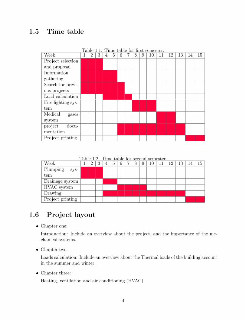
1.5 Time table
Table 1.1: Time table for first semester.Week 1 2 3 4 5 6 7 8 9 10 11 12 13 14 15Project selectionand proposalInformationgatheringSearch for previ-ous projectsLoad calculationFire fighting sys-temMedical gasessystemproject docu-mentationProject printing
Table 1.2: Time table for second semester.Week 1 2 3 4 5 6 7 8 9 10 11 12 13 14 15Plumping sys-temDrainage systemHVAC systemDrawingProject printing
1.6 Project layout
• Chapter one:
Introduction: Include an overview about the project, and the importance of the me-chanical systems.
• Chapter two:
Loads calculation: Include an overview about the Thermal loads of the building accountin the summer and winter.
• Chapter three:
Heating, ventilation and air conditioning (HVAC)
4

• Chapter Four:
Plumbing system: Include an overview about the water supply, drainage system,plumbing materials, water distribution in buildings, water service sizing.
• Chapter five:
Fire fighting system.
• Chapter six:
Medical gases.
• Chapter seven :
Refrigerators.
• Appendix.
5

Chapter 2
Loads Calculation
A heating system is combination of equipment that is used to raise the temperature in anylocation. This can be accomplished several ways, using energy sources such as: solar, oil,wood, electricity and gas. Many systems are used for this purpose, such as heating byhot water or heating by warm air, sometime small heaters are used for this purpose, thereare many criteria’s that will be taken to select the suitable system such as cost, efficiency,flexibility and type of building.
2.1 The composition of heat gains
Heat gains are either sensible, tending to cause a rise in air temperature, or latent, causingan increase in moisture content. In comfort air conditioning sensible gains originate fromthe following sources:
1. Solar radiation through windows.
2. Transmission through the building envelope and by the natural infiltration of warmerair from outside.
3. persons.
4. Electric lighting.
5. Business machines and the like.
2.2 Air conditioning system
HVAC stands stands for heating, ventilating, air-conditioning. it’s a process that simultane-ously conditions air, distributes it combined with the outdoor air to the conditioned spaceand controls and maintains the required space temperature, humidity, air movement, aircleanliness, sound level, and pressure differential within predetermined limits for the healthand comfort of the occupants, for product processing or both.
6

2.2.1 The Cooling load
To determine the size of the necessary refrigeration plant the cooling load should be calcu-lated at about 15.00 h sun-time for the entire building.
2.2.2 Cooling load sources
The cooling loads for a given space consist of the following heat gains:
1. Heat gains that transmitted through building structures such as walls, floors and roofthat are adjacent to unconditioned spaces .The heat transmitted is caused by temper-ature difference that exists on both sides of structures
2. Heat gain due to solar effect which include:
• Solar radiation transmitted through the glass and absorbed by inside surfaces andfurniture.
• Solar radiation absorbed by walls, glass windows, glass doors and roofs that areexposed to solar radiation.
3. Sensible and latent heat gains brought into the space as a result of infiltration of airthrough windows and doors
4. Sensible heat produced in space by lights, appliances, motors and other miscellaneousheat gains.
5. Latent heat produced from cooking, hot baths, or any other moisture producing equip-ment.
6. Sensible and latent heat produced by occupants.
2.3 Overall Heat Transfer Coefficient
The overall heat transfer coefficient represents the total resistance experienced as heat istransferred between fluids or between a fluid and a solid. The overall heat transfer coefficientU can be determined from Eq. 2.1 below:
U =1
1hi
+ Σ∆xiki
+ 1ho
(2.1)
Where:U : Is the overall heat transfer coefficient .hi : Is the inside film heat transfer coefficients.ho : Is the outside film heat transfer coefficients .∆xi: Is the thickness of wall layers.ki: Is the thermal conductivity .The following tables contains all the inside and outside design conditions needed for the
next calculations.
7

• Outdoors design conditions Table 2.1.
Table 2.1: Outdoors design conditions .Season Tout φout hout
oC % kJ/kgSummer 30 55.00 67.00
• Indoors design conditions Table 2.2.
Table 2.2: Indoors design conditionsSeason Tin φin hin
oC % kJ/kgSummer 24 50.00 48.00
• The overall heat transfer coefficient for outside walls Table 2.3. And the section foroutside walls Fig 2.1.
Table 2.3: The overall heat transfer coefficient for outside wallsConstruction material Material thickness Thermal conduction U
[m] [W/m.oC] W/m2oC
1-stone 0.05 1.702-Concrete 0.10 1.753-Insulation 0.03 0.034-Block 0.10 0.955-Plaster 0.02 1.2Total 0.804
Figure 2.1: The section for outside walls
8

• The overall heat transfer coefficient for inside walls Table 2.4. And the section forinside walls Fig 2.2.
Table 2.4: The overall heat transfer coefficient for inside wallsConstruction material Material thickness Thermal conduction U
[m] [W/m.oC] W/m2oC
1-Plaster 0.02 1.22-Block 0.10 0.953-Plaster 0.02 1.2Total 2.45
Figure 2.2: The section for inside walls
• The overall heat transfer coefficient for roof Table 2.5. And the section for the roofFig 2.3.
Table 2.5: The overall heat transfer coefficient for roofConstruction material Material thickness Thermal conduction U
[m] [W/m.oC] W/m2oC
1-Tiles 0.005 0.992-Mortar 0.03 1.403-Sand 0.10 0.304-Bitumen 0.01 0.185-Concrete 0.08 1.756-Block 0.14 0.957-Plaster 0.02 1.20With brick 1.016Without brick 1.194
9

Figure 2.3: The section for roof
• The overall heat transfer coefficient for ground Table 2.6. And the section for theground Fig 2.4.
Table 2.6: The overall heat transfer coefficient for groundConstruction material Material thickness Thermal conduction U
[m] [W/m.oC] W/m2oC
1-Tiles 0.005 0.992-Mortar 0.03 1.403-Sand 0.10 0.304-Bitumen 0.01 0.185-Concrete 0.08 1.75Total 1.038
Figure 2.4: The section for ground
2.4 Cooling Load Calculations
Direct and diffused solar radiation that absorbed by walls and roofs result in raising thetemperature of these surfaces. Amount of radiation absorbed by walls and roofs dependsupon time of the day, building orientation, types of wall construction and presence of shading.
10

2.4.1 Total cooling load calculations for the sample room:
Table 2.7: Area for sample roomRoom Inside wall Outside Wall Ceiling Area Ground Area windows area Doors Area
m2 m2 m2 m2 m2 m2
15 44.76 27.20 54.70 54.70 4.45 3.6
Figure 2.5: Sample room
Heat gain through walls and ceiling:
The calculation of this type of heat gain can be obtained by using the following relation forthe heat transmission through the walls.
Q = U ∗ A ∗∆T (2.2)
Where:
11
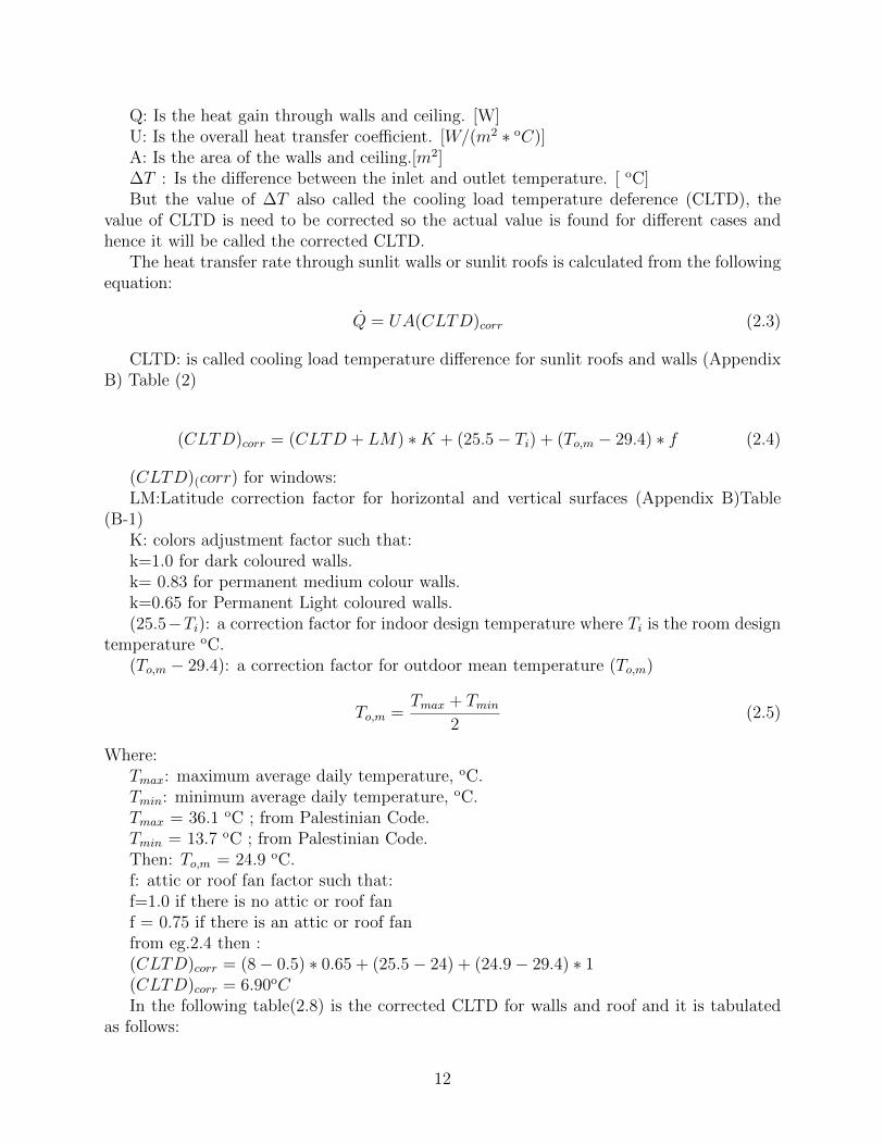
Q: Is the heat gain through walls and ceiling. [W]U: Is the overall heat transfer coefficient. [W/(m2 ∗ oC)]A: Is the area of the walls and ceiling.[m2]∆T : Is the difference between the inlet and outlet temperature. [ oC]But the value of ∆T also called the cooling load temperature deference (CLTD), the
value of CLTD is need to be corrected so the actual value is found for different cases andhence it will be called the corrected CLTD.
The heat transfer rate through sunlit walls or sunlit roofs is calculated from the followingequation:
Q = UA(CLTD)corr (2.3)
CLTD: is called cooling load temperature difference for sunlit roofs and walls (AppendixB) Table (2)
(CLTD)corr = (CLTD + LM) ∗K + (25.5− Ti) + (To,m − 29.4) ∗ f (2.4)
(CLTD)(corr) for windows:LM:Latitude correction factor for horizontal and vertical surfaces (Appendix B)Table
(B-1)K: colors adjustment factor such that:k=1.0 for dark coloured walls.k= 0.83 for permanent medium colour walls.k=0.65 for Permanent Light coloured walls.(25.5−Ti): a correction factor for indoor design temperature where Ti is the room design
temperature oC.(To,m − 29.4): a correction factor for outdoor mean temperature (To,m)
To,m =Tmax + Tmin
2(2.5)
Where:Tmax: maximum average daily temperature, oC.Tmin: minimum average daily temperature, oC.Tmax = 36.1 oC ; from Palestinian Code.Tmin = 13.7 oC ; from Palestinian Code.Then: To,m = 24.9 oC.f: attic or roof fan factor such that:f=1.0 if there is no attic or roof fanf = 0.75 if there is an attic or roof fanfrom eg.2.4 then :(CLTD)corr = (8− 0.5) ∗ 0.65 + (25.5− 24) + (24.9− 29.4) ∗ 1(CLTD)corr = 6.90oCIn the following table(2.8) is the corrected CLTD for walls and roof and it is tabulated
as follows:
12

Table 2.8: CLTD for walls and roofWall CLTD LM CLTDcorr
N 8.00 -0.50 6.90NE 10.00 -0.50 8.20E 13.00 -0.50 10.20SE 12.00 -1.60 8.80S 9.00 -3.30 5.80SW 11.00 -1.60 8.20W 15.00 -0.50 11.50NW 12.00 -0.50 9.50Roof 14.00 0.00 11.20
2.4.2 Sample Calculation
Using patient room 12 at third floor as a sample calculation:
• Heat gain through ceiling QCeiling:
QCeiling = (U1 ∗ A1 + U2 ∗ A2)∆T
Where:
U1 : UCeilingWithbrick.
U2 : UCeilingWithoutbrick.
A1 = 4/5 ∗ ACeilingA2 = 1/5 ∗ ACeilingQCeiling = (1.016 ∗ 4
5∗ 54.7 + 1.194 ∗ 1
5∗ 54.7) ∗ 6
QCeiling = 345[W ] = 0.345[kW ]
• Heat gain through walls QWalls:
AN = (9.8 ∗ 3)− (1.8 ∗ 2) = 25.80m2
AE = (6.8 ∗ 3)− (4.5 ∗ 1) = 15.90
AS = (4 ∗ 3)− (0) = 12.00m2
AW = (3.6 ∗ 3)− (0) = 10.80m2
QN = 2.45 ∗ 25.80 ∗ 6.90 = 0.189kW
QE = 0.804 ∗ 15.90 ∗ 10.2 = 0.131kW
QS = 0.804 ∗ 12 ∗ 5.80 = 0.056kW
QW = 2.45 ∗ 10.80 ∗ 6.90 = 0.079kW
QWalls = 0.189 + 0.131 + 0.056 + 0.079 = 0.455kW
13

• Heat gain through glass QGlas:
QGlas = Qtr + Qconv (2.6)
Where:
Qtr: transmission heat gain.
Qconv: convection heat gain.
Qtr = A ∗ (SHG) ∗ (SC) ∗ (CLF ) (2.7)
Where:
A :glass area,m2
SHG: solar heat gain factor.
SC: shading coefficient.
CLF: cooling load factor.
AE = 6.4 ∗ 1 = 6.4m2
SHG in W/m2 ⇒from (Appendix B)Table (B-7)
E = 678
SC = 0.2⇒ from (Appendix B)Table (B-9)
CLF at 14:00 o’clock⇒ from (Appendix B)Table (B-11)
Qtr.E = 6.4 ∗ 678 ∗ 0.2 ∗ 0.22 = 0.191kW
Qtr = 0.191kW
Qconv. = UA(CLTD)corr
CLTD = 7 oC at 14:00 o’clock ⇒ from (Appendix B)Table (B-12)
k = 1 for glass
f = 1 for glass
Qconv.E = 3.5 ∗ 6.4 ∗ 7 = 0.156kW
Qconv. = 0.156kW
QGlass = 0.191 + 0.156 = 0.347kW
• Heat gain through light QLt.:
QLt. = light intensity ∗ A ∗ (CLF )Lt. ∗ diversity factor (2.8)
light intensity = 10-30 W/m2 for apartment, so we will take 30W/m2.
A: floor area = 54.7m2.
14

(CLF )Lt. = 0.84 ⇒ from (Appendix B)Table (B-14)
Diversity factor = 0.95 ⇒ from (Appendix B)Table (B-15) .
QLt. = 30 ∗ 54.7 ∗ 0.84 ∗ 0.95 = 1.310kW .
• Heat gain through infiltration Qf :
νout = 9.2m/s⇒ from Palestinian Code.
ϑ = 0.88m3/kg ⇒ from psychrometric chart.
ho = 68.13kJ/kg ⇒from psychrometric chart.
hi = 38.5kJ/kg ⇒from psychrometric chart.
Calculate the infiltration air rate and compute the resulting heating load due to infil-tration by using this equation:
Qf =
VfVo∗ (hin − ho)
3600(2.9)
Vf = (k ∗ L ∗ 0.613(S1 ∗ S2 ∗ νo)2)2/3 (2.10)
Where:
Qf : rate of heat transfer due to infiltration, [kW ]
Vf : volumetric flow rate of infiltrated air,[m3/h]
Vo: specific volume of outside air, [m3/kg]
hin: enthalpy at inside conditions, kJ/kg
ho: enthalpy at outside conditions,kJ/kg
k: infiltration coefficient
L: crack length,m.
S1: factor that depends on the topography of the location of the building.
S2: coefficient that depends on the height of the building and the terrain of its location.
Vo: outside air velocity, [m/s].
Vf = 0.7 ∗ 12.3 ∗ (0.613(1 ∗ 0.79 ∗ 9.2)2)2/3 = 87.5m3/h
Qf = [(87.5/0.88) ∗ (67− 48)]/3600 = 0.5kW
• Heat gain through occupants Qoc.:
Qoc. = Qsensible + Qlatent (2.11)
Qsensible = heat gain sensible ∗No.of people ∗ (CLF )oc. ∗Diversity Factor (2.12)
15
Where: (CLF )oc.: cooling load factor due to occupants.
heat gain sensible = 70W ⇒ from (Appendix B)Table (B-17)
No. of people = 16
(CLF )oc. = 0.79 ⇒ from (Appendix B)Table (B-16)
Diversity Factor = 0.6 ⇒ from (Appendix B)Table (B-15)
Qsensible = 70 ∗ 16 ∗ 0.79 ∗ 0.6 = 0.531kW
Qlatent = heat gain latent ∗No.of people ∗Diversity Factor (2.13)
heat gain latent = 44
Qlatent = 44 ∗ 16 ∗ 0.60 = 0.423kW
Qoc. = 0.531 + 0.423 = 0.954kW
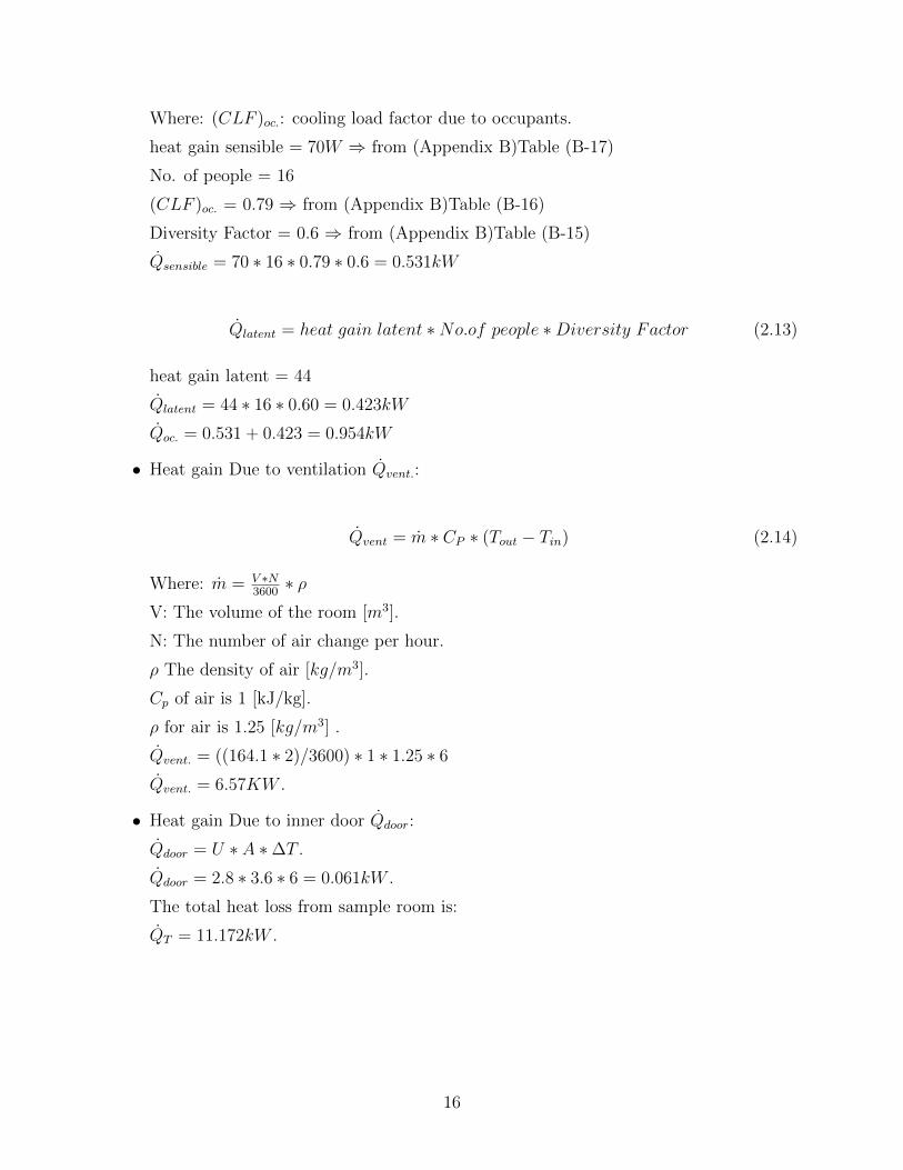
• Heat gain Due to ventilation Qvent.:
Qvent = m ∗ CP ∗ (Tout − Tin) (2.14)
Where: m = V ∗N3600∗ ρ
V: The volume of the room [m3].
N: The number of air change per hour.
ρ The density of air [kg/m3].
Cp of air is 1 [kJ/kg].
ρ for air is 1.25 [kg/m3] .
Qvent. = ((164.1 ∗ 2)/3600) ∗ 1 ∗ 1.25 ∗ 6
Qvent. = 6.57KW .
• Heat gain Due to inner door Qdoor:
Qdoor = U ∗ A ∗∆T .
Qdoor = 2.8 ∗ 3.6 ∗ 6 = 0.061kW .
The total heat loss from sample room is:
QT = 11.172kW .
16

2.5 Heating Load
Heating load is the rate at which heat energy must be supplied to a space to maintain agiven inside design condition.
The heating load of a building consists of the following components:
• Heat loss through all exposed walls, ceiling, floor, windows, doors, and walls betweena heated space and an unheated space (partition walls).
• Heat load required to warm outside cold air infiltrated to heated space through cracks(clearances) of windows and doors, and outside cold air infiltrated due to opening andclosing of doors.
• Domestic hot water load.
• Miscellaneous loads such as emergency heating loads and safety factor heating load.
2.5.1 Heating Load Calculations
The general procedure for calculating the total heating load is:
1. Select the design outdoor air conditions of temperature, humidity, and wind speed andits direction.
2. Select the comfort design indoor conditions of temperature and relative humidity thatmust be maintained in the heated space. ∆T = Tin − Tout
3. Estimate temperature in adjacent unheated space.
∆Tun = 0.5 ∗ (Tin − Tout)
4. Compute the overall heat transfer coefficients for all exposed surfaces of the buildingthrough which heat losses are to be calculated.
5. Determine all surface areas through which heat is lost.
6. Compute the heat loss for each type of walls, floor, ceiling or roof, doors, windows, etc.by using this equation Q = UA(Tin − Tout). Where:
Q: rate of heat transfer, [W]
7. Compute heat loss from bellow-grade walls and floor.
8. Calculate the infiltration air rate and compute the resulting heating load due to infil-tration by using equation(2.9).
9. Assume a safety factor value of 10 to 15% to account for emergency loads.
10. The sum of all the above heat losses for all rooms represents the total heating load ofthe building.
17

The following tables contains all the inside and outside design conditions needed for thenext calculations.
Table 2.9: Outdoors design condition .Season Tout φout hout
oC % kJ/kgWinter 5 65.00 14.00
Table 2.10: Indoors design conditionSeason Tin φin hin
oC % kJ/kgWinter 24 50.00 48.00
2.5.2 Sample Calculation
Using patient room 12 as a sample calculation:
• Heat loss through ceiling QCeiling
QCeiling = (1.016 ∗ 45∗ 54.7 + 1.194 ∗ 1
5∗ 54.7) ∗ 19
QCeiling = 1092[W ] = 1.09[kW ]
• Heat loss through walls QWalls:
QWalls = UWall ∗ AWall ∗∆T
QWalls = 0.804 ∗ 37.80 ∗ 19
QWalls = 2036[W ] = 1.936[kW ]
• Heat loss through unconditioned walls Qun.walls:
Qun.walls = Uun.walls ∗ Aun.walls ∗∆T
Qun.wall = 2.45 ∗ 18.6 ∗ 10[W ] = 0.356[kW ]
• Heat loss through infiltration Qf :
k = 0.70 ;from (Appendix B)Table (B-18)
S1 = 1 ; from (Appendix B)Table (B-19)
S2 = 0.79 ; from Table (Appendix B)Table (B-20)
νo = 12.8m/s ; from Palestinian Code
vo = 0.79m3/kg; from psychrometric chart
ho = 13.03kJ/kg ; from psychrometric chart
hi = 32.9kJ/kg ; from psychrometric chart
L = 12.3[m]
18

Vf = (0.70 ∗ 26.8(0.613(1 ∗ 0.79 ∗ 12.8)2)2/3 = 343m3/h
Qf = [(343/0.79) ∗ (32.9− 13.03)]/3600 = 2.32kW
• Heat loss through windows QWindow :
QWindow = UWindow ∗ AWindow ∗∆T
QWindow = 3.5 ∗ 6.4 ∗ 16
QWindow = 358W = 0.358kW
• Heat loss through doors Qdoor
Qdoors = Udoors ∗ Adoors ∗∆T
Qdoors = 2.8 ∗ 3.6 ∗ 10 = 301W
Qdoors = 0.301kW
• Take Safety Factor 15%
The total heat loss from sample room is:
QT = 7.3kW
2.6 Total cooling and heating loads for hospital.
• O.P :Operating Room.
• P.R :Patients Room.
• R.R :Recovery Room.
• D.R :Doctors Room.
• XR.R:X Rays Room.
• W.R:Waiting Room.
• K.R:Kitchen Room.
Table 2.11: Total cooling and heating loads for basement floorNo Room Cooling load Heating load
kW kW
1 D.R 1 12.1 9.62 D.R 2 11.7 8.53 D.R 3 12.3 9.14 D.R 4 10.9 7.95 K.R 1 10.3 9.86 K.R 2 10.9 9.97 W.R 11.5 9.1
Total 68.7 53.5
19
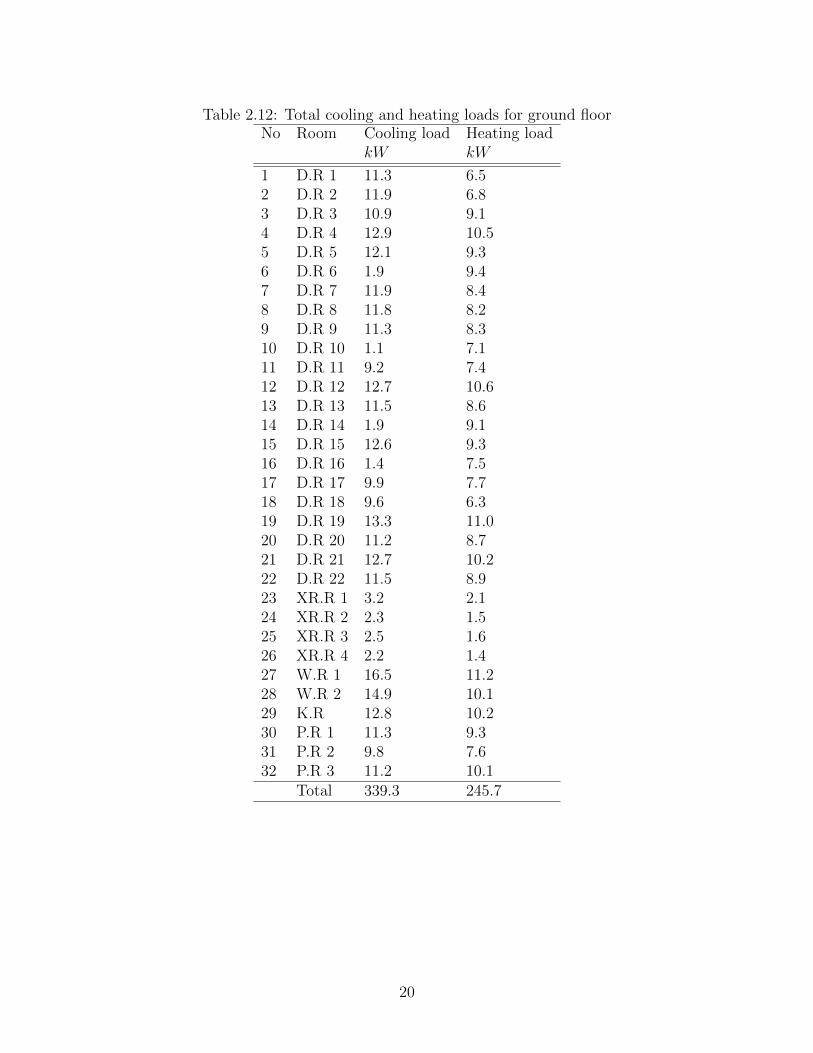
Table 2.12: Total cooling and heating loads for ground floorNo Room Cooling load Heating load
kW kW
1 D.R 1 11.3 6.52 D.R 2 11.9 6.83 D.R 3 10.9 9.14 D.R 4 12.9 10.55 D.R 5 12.1 9.36 D.R 6 1.9 9.47 D.R 7 11.9 8.48 D.R 8 11.8 8.29 D.R 9 11.3 8.310 D.R 10 1.1 7.111 D.R 11 9.2 7.412 D.R 12 12.7 10.613 D.R 13 11.5 8.614 D.R 14 1.9 9.115 D.R 15 12.6 9.316 D.R 16 1.4 7.517 D.R 17 9.9 7.718 D.R 18 9.6 6.319 D.R 19 13.3 11.020 D.R 20 11.2 8.721 D.R 21 12.7 10.222 D.R 22 11.5 8.923 XR.R 1 3.2 2.124 XR.R 2 2.3 1.525 XR.R 3 2.5 1.626 XR.R 4 2.2 1.427 W.R 1 16.5 11.228 W.R 2 14.9 10.129 K.R 12.8 10.230 P.R 1 11.3 9.331 P.R 2 9.8 7.632 P.R 3 11.2 10.1
Total 339.3 245.7
20

Table 2.13: Total cooling and heating loads for first floorNo Room Cooling load Heating load
kW kW
1 P.R 1 12.8 7.32 P.R 2 11.1 7.83 P.R 3 9.9 7.24 P.R 4 10.9 7.15 P.R 5 10.3 6.66 P.R 6 10.4 6.87 P.R 7 10.2 6.58 P.R 8 11.1 7.39 P.R 9 10.6 7.010 P.R 10 10.5 7.111 P.R 11 11.9 7.712 P.R 12 11.3 7.613 P.R 13 11.9 8.014 P.R 14 10.8 6.915 P.R15 10.9 7.216 R.R 1 7.3 4.417 R.R 2 7.9 5.118 R.R 3 6.1 3.919 R.R 4 6.1 3.920 R.R 5 6.8 4.921 R.R 6 11.5 7.622 D.R 1 10.7 7.123 D.R 2 10.2 6.524 D.R 3 7.9 4.525 D.R 4 6.2 3.926 D.R 5 5.8 3.627 D.R 6 3.1 1.928 D.R 7 1.9 1.229 D.R 8 2.2 1.330 D.R 9 11.6 8.231 O.R 1 12.8 7.332 O.R 2 12.3 7.133 O.R 3 14.6 10.134 O.R 4 11.1 6.935 O.R 5 13.1 8.236 W.R 12.2 9.937 XR.R 1 10.9 6.538 XR.R 2 11.2 7.339 XR.R 3 9.7 6.440 XR.R 4 11.5 11.8
Total 383.8 215.6
21

Table 2.14: Total cooling and heating loads for second floorNo Room Cooling load Heating load
kW kW
1 P.R 1 15.3 12.92 P.R 2 11.1 8.13 P.R 3 12.2 11.24 P.R 4 1.2 11.25 P.R 5 11.9 10.96 P.R 6 11.8 9.17 P.R 7 12.2 9.78 P.R 8 10.3 7.19 P.R 9 10.5 7.510 P.R 10 10.3 7.611 P.R 11 11.9 6.512 P.R 12 10.2 7.213 R.R 1 6.2 4.214 R.R 2 7.5 4.315 R.R 3 5.7 4.116 R.R 4 6.4 3.817 D.R 1 8.2 4.218 D.R 2 8.4 3.819 D.R 3 6.1 3.920 D.R 4 11.3 8.921 D.R 5 6.6 4.222 O.R 1 14.2 9.923 O.R 2 12.2 8.724 W.R 1 10.3 9.125 W.R 2 10.9 9.526 XR.R 1 12.1 10.327 XR.R 2 11.3 9.328 K.R 6.8 3.5
Total 266.3 175.6
22
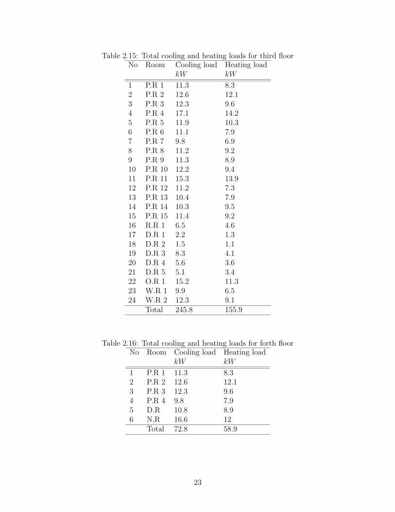
Table 2.15: Total cooling and heating loads for third floorNo Room Cooling load Heating load
kW kW
1 P.R 1 11.3 8.32 P.R 2 12.6 12.13 P.R 3 12.3 9.64 P.R 4 17.1 14.25 P.R 5 11.9 10.36 P.R 6 11.1 7.97 P.R 7 9.8 6.98 P.R 8 11.2 9.29 P.R 9 11.3 8.910 P.R 10 12.2 9.411 P.R 11 15.3 13.912 P.R 12 11.2 7.313 P.R 13 10.4 7.914 P.R 14 10.3 9.515 P.R 15 11.4 9.216 R.R 1 6.5 4.617 D.R 1 2.2 1.318 D.R 2 1.5 1.119 D.R 3 8.3 4.120 D.R 4 5.6 3.621 D.R 5 5.1 3.422 O.R 1 15.2 11.323 W.R 1 9.9 6.524 W.R 2 12.3 9.1
Total 245.8 155.9
Table 2.16: Total cooling and heating loads for forth floorNo Room Cooling load Heating load
kW kW
1 P.R 1 11.3 8.32 P.R 2 12.6 12.13 P.R 3 12.3 9.64 P.R 4 9.8 7.95 D.R 10.8 8.96 N.R 16.6 12
Total 72.8 58.9
23

Chapter 3
Heating, Ventilation and AirConditioning (HVAC)
3.1 Variable Refrigerant Flow (VRF) Systems
3.1.1 Overview
The primary function of all air-conditioning systems is to provide thermal comfort for build-ing occupants. There are a wide range of air conditioning systems available, starting from thebasic window-fitted units to the small split systems, to the medium scale package units, tothe large chilled water systems, and currently to the variable refrigerant flow (VRF) systems.
The term VRF refers to the ability of the system to control the amount of refrigerantflowing to each of the evaporators, enabling the use of many evaporators of differing capaci-ties and configurations, individualized comfort control, simultaneous heating and cooling indifferent zones, and heat recovery from one zone to another. VRF systems operate on thedirect expansion (DX) principle meaning that heat is transferred to or from the space directlyby circulating refrigerant to evaporators located near or within the conditioned space. Re-frigerant flow control is the key to many advantages as well as the major technical challengeof VRF systems.
3.1.2 Variable Refrigerant Flow (VRF) Systems
Variable refrigerant flow (VRF) is an air-condition system configuration where there is oneoutdoor condensing unit and multiple indoor units. The term variable refrigerant flow refersto the ability of the system to control the amount of refrigerant flowing to the multipleevaporators (indoor units), enabling the use of many evaporators of differing capacities andconfigurations connected to a single condensing unit. The arrangement provides an individ-ualized comfort control, and simultaneous heating and cooling in different zones.
Currently widely applied in large buildings . The VRF technology/system was developedand designed by Daikin Industries, Japan who named and protected the term variable refrig-erant volume (VRV) system so other manufacturers use the term VRF ”variable refrigerantflow”. In essence both are same. With a higher efficiency and increased controllability, the
24

VRF system can help achieve a sustainable design. Unfortunately, the design of VRF sys-tems is more complicated and requires additional work compared to designing a conventionaldirect expansion (DX) system.
VRF systems are similar to the multi-split systems which connect one outdoor section toseveral evaporators. However, multi-split systems turn OFF or ON completely in responseto one master controller, whereas VRF systems continually adjust the flow of refrigerant toeach indoor evaporator. The control is achieved by continually varying the flow of refrigerantthrough a pulse modulating valve (PMV) whose opening is determined by the microprocessorreceiving information from the thermistor sensors in each indoor unit. The indoor units arelinked by a control wire to the outdoor unit which responds to the demand from the indoorunits by varying its compressor speed to match the total cooling and/or heating requirements.VRF systems promise a more energy-efficient strategy (estimates range from 11% to 17%less energy compared to conventional units) at a somewhat higher cost.
Figure 3.1: VRF system with multiple indoor evaporator units
The modern VRF technology uses an inverter-driven scroll compressor and permits asmany as 48 or more indoor units to operate from one outdoor unit (varies from manufacturerto manufacturer). The inverter scroll compressors are capable of changing the speed to followthe variations in the total cooling/heating load as determined by the suction gas pressuremeasured on the condensing unit. The capacity control range can be as low as 6% to 100%.Refrigerant piping runs of more than 200 ft are possible, and outdoor units are available insizes up to 240,000 Btuh. A schematic VRF arrangement is indicated below:
25

Figure 3.2: A schematic VRF arrangement
VRF systems are engineered systems and use complex refrigerant and oil control circuitry.The refrigerant pipe-work uses a number of separation tubes and/or headers (refer schematicfigure above). A separation tube has 2 branches whereas a header has more than 2 branches.Either of the separation tube or header, or both, can be used for branches. However, theseparation tube is NEVER provided after the header because of balancing issues.
Figure 3.3: A schematic VRF arrangement
26

3.1.3 Building Load Profile
When selecting a VRF system for a new or retrofit application, the following assessmenttasks should be carried out:
• Determine the functional and operational requirements by assessing the cooling loadand load profiles including location, hours of operation, number/type of occupants,equipment being used, etc.
• Determine the required system configuration in terms of the number of indoor unitsand the outdoor condensing unit capacity by taking into account the total capacityand operational requirements, reliability and maintenance considerations.
Figure 3.4: Indoor and out door capacity
• Size of P1: Depends on the total capacity of (Q1+Q2+Q3)
• Size of P2: Depends on the total capacity of (Q4+Q5+Q6)
• Size of P3: Depends on the total capacity of (Q4)
3.1.4 Building Load Profile
When selecting a VRF system for a new or retrofit application, the following assessmenttasks should be carried out:
1. Installation Advantages. VRF systems are lightweight and modular. Each module canbe transported easily and fits into a standard elevator.
2. Design Flexibility. A single condensing unit can be connected to many indoor units ofvarying capacity (e.g., 0.5 to 4 tons [1.75 to 14 kW]) and configurations (e.g., ceilingrecessed, wall mounted, floor console). Current products enable up to 20 indoor unitsto be supplied by a single condensing unit. Modularity also makes it easy to adaptthe HVAC system to expansion or reconfiguration of the space, which may requireadditional capacity or different terminal units.
3. Maintenance and Commissioning. VRF systems with their standardized configurationsand sophisticated electronic controls are aiming toward near plug-and-play commission-ing.
27

4. Comfort. Many zones are possible, each with individual set point control. BecauseVRF systems use variable speed compressors with wide capacity modulation capabil-ities, they can maintain precise temperature control, generally within ±1oF (±0.6oC),according to manufacturers , literature.
5. Energy Efficiency. The energy efficiency of VRF systems derives from several factors.The VRF essentially eliminates duct losses, which are often estimated to be between(10-20) percent of total airflow in a ducted system.VRF systems typically includetwo to three compressors, one of which is variable speed, in each condensing unit,enabling wide capacity modulation. This approach yields high part-load efficiency,which translates into high seasonal energy efficiency, because HVAC systems typicallyspend most of their operating hours in the range of 40% to 80% of maximum capacity.
6. Refrigerant piping runs of more than 200 feet (60.96 m) are possible and outdoor unitsare available in sizes up to 240,000 Btu/ h (60478.98 kW).
3.1.5 Selection units
This section talks about selection of outdoor and indoor units of VRF system, depend-ing on the “Samsung VRF catalogue”, since this company product exists in Hebron.Outdoor and indoor units are selected according to the thermal load of the building.
Outdoor unit
We are chosen three compact packages outdoor units tow packages individual for threeunits and the third individual for tow units, with capacity 48 HP,46 HP and 20 HP .
Figure 3.5: Out door units
28

Table 3.1: Outdoor unit details for basement and ground floors.Unit Cooling Load (HP) Cooling load (kW ) Outdoor Unit Name
Unit 1-1 16 RVXVHT160GEUnit 1-2 16 137.4 RVXVHT160GEUnit 1-3 16 RVXVHT160GEUnit 2-1 14 RVXVHT140GEUnit 2-2 16 128.5 RVXVHT160GEUnit 2-3 16 RVXVHT160GEUnit 3-1 10 56 RVXVHT100GEUnit 3-2 10 RVXVHT100GE
Indoor unit
In this project there are two types of indoor units selected, which are split and cassette units.The figure below shows the two types of selected units:
Figure 3.6: Split unit
Figure 3.7: Cassette unit
29

The selected indoor units for the basement and ground floor are listed in the tables below:
Table 3.2: Outdoor unit detailsIndoor Unit Type Cooling load (kW ) Indoor Unit Name Quantity
Cassette(4 way) 11.2 AVXC4H112E 15Cassette(4 way) 12.8 AVXC4H128E 2Cassette(4 way) 14 AVXC4H140E 8Split(Neoforte) 5.6 AVXWNH056EE 17Split(Neoforte) 7.1 AVXWNH071EE 10
3.2 Mechanical ventilation
3.2.1 Overview of ventilation
Ventilation is the process of supplying and removing air by natural or mechanical means toand from a building. The design of a buildings ventilation system should meet the minimumrequirements of the building (Ventilating Systems) regulations. There are two ways forVentilation:
1. Natural ventilation:- covers uncontrolled inward air leakage through cracks, windows,doorways and vents (infiltration) as well as air leaving a room (exfiltration) throughthe same routes. Natural ventilation is strongly affected by weather conditions and isoften unreliable.
2. Mechanical: - or forced ventilation is provided by air movers or fans in the wall, roofor air conditioning system of a building. It promotes the supply or exhaust airflow ina controllable manner.
The airflow rate into a room space, for general mechanical supply and extract systems, isusually expressed in:
1. Air changes per hour. An air change per hour (ACH) is the most frequently used basisfor calculating the required airflow. Air changes per hour are the number of times inone hour an equivalent room volume of air will be introduced into, or extracted fromthe room space.
2. Airflow rate per person. Airflow rate per person are generally expressed as litersper person (L/P), and are usually used where fresh air ventilation is required withinoccupied spaces.
3. Airflow rate per unit floor area. Airflow rates per unit floor area are similar in effect toair changes per hour except that the height of the room is not taken into consideration.Mechanical ventilation system in this project is just for bathrooms and kitchens & byfirst method air changes per hour.
30
3.2.2 Objectives of ventilation
Ventilation in a building serves to provide fresh and clean air, to maintain a thermally com-fortable work environment, and to remove or dilute airborne contaminants in order to preventtheir accumulation in the air. Air conditioning is a common type of ventilation system inmodern office buildings. It draws in outside air and after filtration, heating or cooling andhumidification circulates it throughout the building. A small portion of the return air isexpelled to the outside environment to control the level of indoor air contaminants.
Designing of mechanical ventilation
Steps of designing mechanical ventilation:
1. Calculate the required ventilating rate of air by using “Ventilation Rates Calculator”software.
2. Calculate the volume of the room in (m3)
3. Calculate the flow rate of air by using air changes per hour method
4. converts the value to cubic feet per minute (CFM).
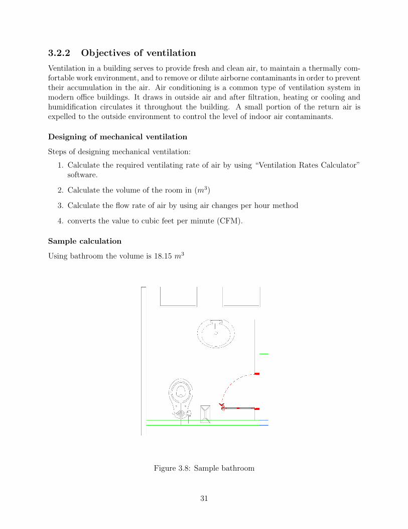
Sample calculation
Using bathroom the volume is 18.15 m3
Figure 3.8: Sample bathroom
31

Figure 3.9: Sample calculation of ventilation
Table 3.3: : Ventilation rateRoom Volume Ventilating Rate Ventilating Rate
(m3) (L/s) (CFM)
Kitchen 240 88 186.5Bathrooms* 525 1458 3089.3
32
Chapter 4
Plumbing System
4.1 Introduction
In order to maintain daily operations and patient care services, health care facilities need todevelop an Emergency Water Supply Plan (EWSP) to prepare for, respond to, and recoverfrom a total or partial interruption of the facilities’ normal water supply. Water supplyinterruption can be caused by several types of events such as natural disaster, a failure ofthe community water system, construction damage or even an act of terrorism. Becausewater supplies can and do fail, it is imperative to understand and address how patientsafety, quality of care, and the operations of your facility will be impacted. Below are a fewexamples of critical water usage in a health care facility that could be impacted by a wateroutage. Water may not be available for:
• Hand washing and hygiene.
• Drinking at faucets and fountains.
• Food preparation.
• Flushing toilets and bathing patients.
• Laundry and other services provided by central services (e.g., cleaning and sterilizationof surgical instruments).
• Reprocessing of medical equipment (e.g., endoscopes, surgical instruments, and acces-sories) after use on a patient.
• Patient care (e.g., hemodialysis, hemofiltration, extracorporeal membrane oxygenation,hydrotherapy).
• Radiology.
• Fire suppression sprinkler systems.
• Water-cooled medical gas and suction compressors (a safety issue for patients on ven-tilation).
33

• Heating, ventilation, and air conditioning (HVAC).
• Decontamination/hazmat response.
A health care facility must be able to respond to and recover from a water supply inter-ruption. A robust EWSP can provide a road map for response and recovery by providingthe guidance to assess water usage, response capabilities, and water alternatives.
The Emergency Water Supply Planning Guide for Hospitals and Health Care Facilitiesprovides a four step process for the development of an EWSP:
1. Assemble the appropriate EWSP Team and the necessary background documents foryour facility;
2. Understand your water usage by performing a water use audit;
3. Analyze your emergency water supply alternatives; and
4. Develop and exercise your EWSP
The EWSP will vary from facility to facility based on site-specific conditions, but willlikely include a variety of emergency water supply alternatives evaluated in step #3 above.How the EWSP is developed for a health care facility will depend on the size of the facility.For a small facility, one individual may perform multiple functions, and the process may berelatively simple with a single individual preparing an EWSP of only a few pages. However,for a large regional hospital, multiple parties will need to work together to develop an EWSP.In this case the process and the plan would be more complex. However, regardless of size, ahealth care facility must have a robust EWSP to be prepared to ensure patient safety andquality of care while responding to and recovering from a water emergency.
4.2 Water Supply system
4.2.1 Calculations of hot and cold water supply systems
To determine the pipe size for cold and hot water supply system the water supply fixtureunit (WSFU) for each fixture unit must be determined and total fixture unit on each pipingrun out be calculated, the minimum floor pressure required at the critical fixture unit mustbe determined.
Example: calculation of water supply unit (WSFU) in the Bathroom shown fig4.1. Therewas three fixtures (shower, lavatory, and water closet with flush valve) each have (WSFU)as following Table 4.1 WSFU of cold and hot water for the bath room.
34

Figure 4.1: Sample path room
Table 4.1: WSFU of cold and hot water for the bath room.Fixture No. of Load from Total of WSFU Total of WSFU for Total of WSFU ForUnit Units table public for cold water hot water hot and cold water
Water closet 1 3 3 - 3Lavatory 1 3/4*1 0.75 0.75 1Bath tub 1 3/4*2 1.5 1.5 2
Σ =5.25 WSFU Σ =2.25 WSFU Σ =6 WSFU
The following Table 4.2 shown WSFU of cold and hot water for basement floor.
35

Table 4.2: WSFU of cold and hot water for the basement floor.Fixture No. of Load from Total of WSFU Total of WSFU for Total of WSFU ForUnit Units table public for cold water hot water hot and cold water
Water closet 4 3 12 - 12Lavatory 7 3/4*1 5.25 5.25 7Sink 10 3/4*2 15 15 20Bath tub 3 3/4*2 4.5 4.5 6
Σ =36.75 WSFU Σ =24.75 WSFU Σ =45 WSFU
The following Table 4.3 WSFU of cold and hot water for ground floor.
Table 4.3: WSFU of cold and hot water for the ground floor.Fixture No. of Load from Total of WSFU Total of WSFU for Total of WSFU ForUnit Units table public for cold water hot water hot and cold water
Water closet 40 3 120 - 120Lavatory 46 3/4*1 34.5 34.5 46Sink 5 3/4*2 7.5 7.5 10Bath tub 5 3/4*2 7.5 7.5 10
Σ =169.5 WSFU Σ =49.5 WSFU Σ =186 WSFU
The following Table 4.4 WSFU of cold and hot water for first floor.
Table 4.4: WSFU of cold and hot water for the first floor.Fixture No. of Load from Total of WSFU Total of WSFU for Total of WSFU ForUnit Units table public for cold water hot water hot and cold water
Water closet 19 3 57 - 57Lavatory 21 3/4*1 15.75 15.57 21Bath tub 17 3/4*2 25.5 25.5 34
Σ =98.25 WSFU Σ =41.25 WSFU Σ =112 WSFU
The following Table 4.5 WSFU of cold and hot water for second floor.
Table 4.5: WSFU of cold and hot water for the second floor.Fixture No. of Load from Total of WSFU Total of WSFU for Total of WSFU ForUnit Units table public for cold water hot water hot and cold water
Water closet 16 3 48 - 48Lavatory 18 3/4*1 13.5 13.5 18Bath tub 12 3/4*2 18 18 24
Σ =79.5 WSFU Σ =31.5 WSFU Σ =90 WSFU
The following Table 4.6 WSFU of cold and hot water for third floor.
36

Table 4.6: WSFU of cold and hot water for the third floor.Fixture No. of Load from Total of WSFU Total of WSFU for Total of WSFU ForUnit Units table public for cold water hot water hot and cold water
Water closet 21 3 63 - 63Lavatory 22 3/4*2 16.5 16.5 22Bath tub 14 3/4*2 21 21 28
Σ =100.5 WSFU Σ =37.5 WSFU Σ =113 WSFU
The following Table 4.7 WSFU of cold and hot water for fourth floor.
Table 4.7: WSFU of cold and hot water for the fourth floor.Fixture No. of Load from Total of WSFU Total of WSFU for Total of WSFU ForUnit Units table public for cold water hot water hot and cold water
Water closet 2 3 6 - 6Lavatory 6 3/4*1 4.5 4.5 6Bath tub 6 3/4*2 9 9 12
Σ =19.5 WSFU Σ =13.5 WSFU Σ =24 WSFU
4.2.2 Flow rate calculations
By using table (B-21 / Appendix B) for supply system predominantly for flush tank forground floor the estimating demand in gpm for cold water = 106.5 WSFU. So, by usinginterpolation = 8.75 gpm. Now we calculate the (gpm) for each floor so, (gpm) for each flooras in the following tables 4.8:
Table 4.8: The WSFU and gpm for all floors.No. of Total No. Total No. Total No. Total No. Total No. Total No.
of WSFU of WSFU of WSFU of gpm of gpm of gpmfor cold for for hot& for cold for for hot &
Floor water hot water cold water water hot water cold water
Basement 36.75 24.75 45 23.75 16.85 27Ground 169.5 49.5 186 58.9 28.8 62.2First 98.25 41.25 112 43.65 25.5 47Second 79.5 31.5 90 38.85 20.75 41.5Third 100.5 37.5 113 44.125 23.75 47.25Fourth 19.5 13.5 24 13.7 10.1 15.8
4.2.3 Pipe size calculations
The maximum instantaneous water demand on:
1. The amount of total WSFU for cold water = 504 WSFU.
37
2. The amount of total WSFU for hot water = 198 WSFU.
The total WSFU for cold and hot water = 702 WSFU.So, the total demand for cold and hot water = 161.36 gpm.The available mains pressure at the level outlet is:Main pressure = static head pressure + friction head pressure + main flow pressureStatic head = [height of floors + height of water tank + height of stairs well – height of
fixture unit]Height of floors = 3 mHeight of stairs well = 3mHeight of water tank as selected = 2mHeight of sink = 1.05mSo we find Conversion meter to ft1ft = 12 in * 2.54 cm = 30.48 cmSo, the static head = 3 + 2 + 3 – 1.05 = 6.95 m = 22.796 ftStatic pressure = 22.796 * 0.433 = 9.87 psiTotal equivalent length (TEL): the distance from water tanks to the collector in ground
floor + distance from collector to fixture unitTEL = longest run * 1.5TEL= 39 * 1.5 = 58.5 ftMain flow pressure of the critical fixture = 8 psiFriction head = static pressure – main flow pressure = 9.87 – 8 = 1.87 psiUniform friction loss = friction head / TEL = 1.87 / 58.5 =1.87 / (0.585 *100)Uniform friction loss = 3.19 psi/100ft
Selection of water pipes diameters:
By using chart of friction head loss (figure B-22 / Appendix B) for galvanized steel pipes weselect diameters of pipes refer to calculated values of the main pipe that supply cold waterfrom tanks to distribution points on the roof .The diameter is 2.5” refer to calculated valuesfor flow rate (125.72 gpm) , and friction head loss(3.19 psi/100ft) for riser. We have 2 risersin two regions.
The following table 4.9 shows the diameters of hot and cold water pipes for all floors.we select two-pump standby WB200/185D from NINGBO YINZHOU H.T. INDUSTRY
COMPANY.
38

Table 4.9: Diameter of pipe sizing of water supply in inch for each floor.No. No. Total load Total load Friction Diameter Diameterof of of cold of hot of of cold of hotfloor collector water (gpm) water (gpm) head loss water pipe water pipe
1 9.65 5.65 2.72 1” 3/4”
Basement 2 8.6 7.25 2.19 1” 3/4”
3 8.6 7.25 2.19 1” 3/4”
1 17.3 6.125 2.14 114
”3/4”
2 11 5 3.62 1” 3/4”
3 6.1 1.5 4.2 3/4” 3/4”
4 6.12 5 4 3/4” 3/4”
Ground 5 22.62 6.68 3.52 114
”1”
6 8.6 5 2.3 1” 3/4”
7 11.09 4 3.62 1” 3/4”
8 13.7 6.57 2.62 114
”1”
9 12.65 3 4.69 1” 3/4”
10 12.65 3 4.69 1” 3/4”
1 11 5 3.62 1” 3/4”
2 11 5 3.62 1” 3/4”
3 8.25 4.6 2.13 1” 3/4”
4 6.1 4 4.2 3/4” 3/4”
First 5 11 5 2.55 1” 3/4”
6 5 3.5 2.8 3/4” 3/4”
7 8.75 5 2.37 1” 3/4”
8 12.65 8.56 4.69 1” 3/4”
1 6.4 4 4.2 3/4” 3/4”
2 11 5 2.55 1” 3/4”
3 11 5 3.62 1” 3/4”
Second 4 8.25 4.6 2.13 1” 3/4”
5 5 3.5 2.8 3/4” 3/4”
6 8.25 5 2.13 1” 3/4”
7 8.75 5 2.37 1” 3/4”
1 11 5 3.62 1” 3/4”
2 13.65 5 5.4 1” 3/4”
3 11 5 3.62 1” 3/4”
4 11 5 3.62 1” 3/4”
Third 5 5 3 2.8 3/4” 3/4”
6 6 2.7 3.92 3/4” 3/4”
7 8.75 5 2.37 1” 3/4”
8 8.25 5 2.13 1” 3/4”
1 5 5 2.8 3/4” 3/4”
Fourth 2 5.56 5.56 3.41 3/4” 3/4”
3 6.125 5 4.07 3/4” 3/4”
39
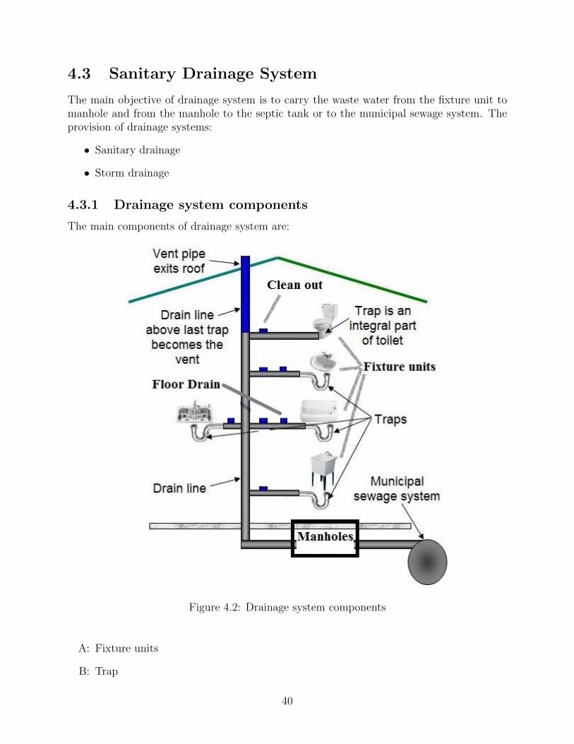
4.3 Sanitary Drainage System
The main objective of drainage system is to carry the waste water from the fixture unit tomanhole and from the manhole to the septic tank or to the municipal sewage system. Theprovision of drainage systems:
• Sanitary drainage
• Storm drainage
4.3.1 Drainage system components
The main components of drainage system are:
Figure 4.2: Drainage system components
A: Fixture units
B: Trap
40
C: Clean out
D: Drainage pipe
E: Stack and vent pipes
F: Manholes
G: Septic tank or municipal sewage system
H: Accessories
4.3.2 Sanitary drainage
procedure and pipe sizing
Pipe size is calculated by using a concept of fixture units (DFU) instead of using gpm ofdrainage water. This unit takes into account not only the fixtures water use but also itsfrequency of use, which is the DFU has a built–in diversity factor. This enables us, exactlyas for water supply to add DFU of various fixtures to obtain the maximum expected drainageflow. Drainage pipes sized for a particular number of drainage fixture units, according toTables (B-21, B-22, B-23)/ Appendix B. These tables are built into the fill factors, whichare:
* 50% fill in branches (horizontal pipes)
* (25-33)% fills in stack (vertical pipes)
* 50% fill in building and swear drains
The recommended velocity for drainage piping:
* For branches the recommended velocity is 2 ft/s.
* For building pipes the recommended velocity is 3 ft/s.
* For greasy flow the recommended velocity is 4 ft/s.
Velocity of water flow through drainage piping depends on:
* Pipe diameter.
* Slope.
Design procedure:
1: Calculation of the number of DFU for each branch .
2: Calculation of the number of DFU for each stack.
3: Choosing the branch pipe diameter.
41

4: Choosing the stack pipe diameter .
5: Comparing the stack pipe diameter with branch diameter.
6: Choosing the building drain pipe diameter .
To achieve the recommended velocities which are 3 fps in building drain, it will be chosenthe slope and flow velocity in building drain.
The following figure 4.3 and shows sample of stacks:
Figure 4.3: Sample of stacks
The following Table 4.10 will show the drainage fixture unit (dfu).
42

Table 4.10: The drainage fixture unit (dfu).Stake dfu value Diameter of pipe [inch]
A 55 4B 26 4C 75 4D 11 4E 26 4F 32 4G 26 4H 40 4I 40 4J 40 4K 27 4L 47 4M 89 4N 41 4O 47 4P 26 4Q 46 4R 42 4S 42 4T 29 4U 39 4V 9 4W 7 4X 7 4Y 9 4Z 9 4
A1 12 4A2 28 4A3 22 4A4 42 4A5 53 4A6 42 4A7 41 4
4.3.3 Manhole design
The main purpose of the manholes is to carry the water from stacks to various drainagepoints.
We design the manhole around the building so as that the sewage comes from the stacksflows in, then the sewage flows from one manhole to another so as reaching the septic tank. The design of the manholes depend on the ground and its nature around the building,and so as the first manhole height should not be less than 50 cm. and then we calculate the
43

height of the other manhole depending on the spacing between manholes and the slope ofdrainage pipes between manhole to be1.5%.
As a result of these calculations we estimate the invert level of the manhole that is thedepth of the pipe entering the manhole and we choose the diameter of the manhole dependingon the depth of the manhole as below.
φ 60 cm for manhole depth (50-100) cm.φ 80 cm for manhole depth (100-150) cm.φ 100 cm for manhole depth (150-250) cm.φ 120 cm for manhole depth(250-∞) cm.
Manholes Calculations
The depth of the first manhole is 60 cm, the calculation of the second manhole done accordingto the first manhole and so on. Using the following steps we does the calculations: Depth:(DepthManholes(x) = (DepthManholes(x−1) + (Slope ∗Distance) + 5 + LevelDifference)[cm]
Top level: Manholes face level on the groundOutlet level = Top level-Depth MAN [m]Invert level = Outlet Level of MAN + 5 [m]The figure 4.4 below shows the details of the manholes:
Figure 4.4: The details of the manholes.
We assume the depth of the first manhole to be (60 cm) and we calculate the secondmanhole according to it and so on.
For Manhole.1:Top level = 0.0 mDepth = 0.6Outlet level=Top level-Depth = 0.0- 0.6 = -0.6 mFor MAN.2:
44

The distance between MAN.1 & MAN.2 is 8 m. Depth of MAN.2 is: Depth = 60+(.015*800)+5+0=77 cm Outlet level MAN.2 =Top level-Depth MAN.2= 0.0- 0.77 = -0.77m Slope is 1.5Invertlevel of MAN.2 = Outlet Level of MAN.2 + 5 cm= -0.72 m
The following table 4.11 shows calculations and dimensions of all manholes that used inour project.
Drop Manholes
When a sewer connects with another sewer, where the difference in level between invert levelof branch sewer and water line in the main sewer at maximum discharge is greater than 0.6m, a manhole may be built either with vertical or nearly vertical drop pipe from higher sewerto the lower one (Figure 4.5). The drop manhole is also required in the same sewer line insloping ground, when drop more than 0.6 m is required to control the gradient and to satisfythe maximum velocity i.e., non-scouring velocity.
The drop pipe may be outside the shaft and encased in concrete or supported on bracketsinside the shaft. If the drop pipe is outside the shaft, a continuation of the sewer should bebuilt through the shaft wall to form a rodding and inspection eye, provided with half blankflange (Figure 4.5). When the drop pipe is inside the shaft, it should be of cast iron andprovided with adequate arrangements for rodding and with water cushion of 150 mm depthat the end. The diameter of the drop pipe should be at least equal to incoming pipe.
Figure 4.5: The details of the manholes.
45
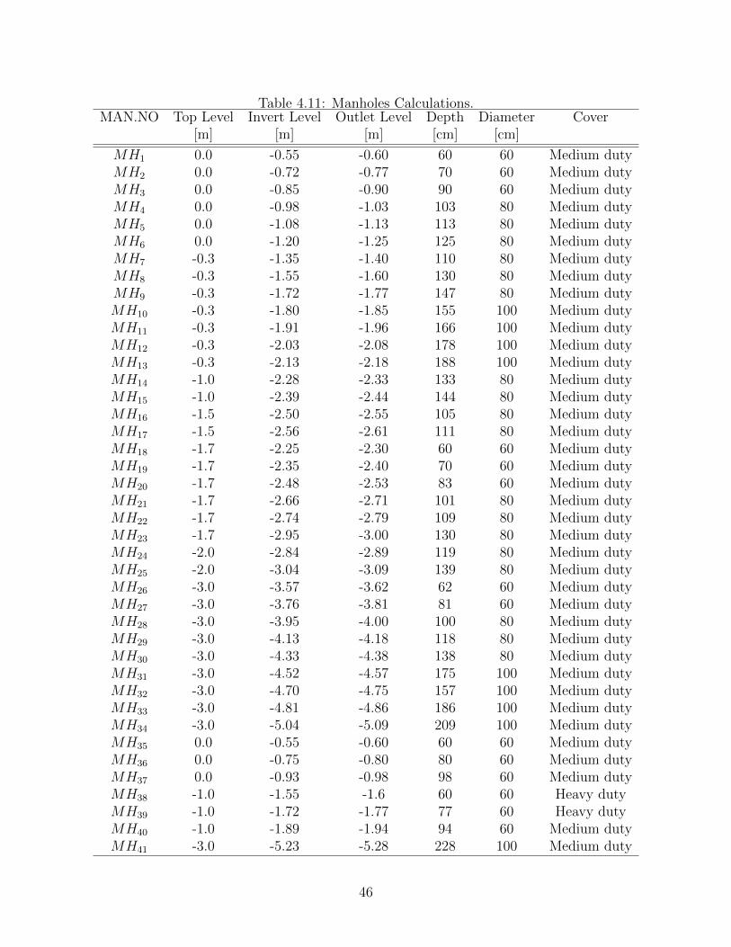
Table 4.11: Manholes Calculations.MAN.NO Top Level Invert Level Outlet Level Depth Diameter Cover
[m] [m] [m] [cm] [cm]
MH1 0.0 -0.55 -0.60 60 60 Medium dutyMH2 0.0 -0.72 -0.77 70 60 Medium dutyMH3 0.0 -0.85 -0.90 90 60 Medium dutyMH4 0.0 -0.98 -1.03 103 80 Medium dutyMH5 0.0 -1.08 -1.13 113 80 Medium dutyMH6 0.0 -1.20 -1.25 125 80 Medium dutyMH7 -0.3 -1.35 -1.40 110 80 Medium dutyMH8 -0.3 -1.55 -1.60 130 80 Medium dutyMH9 -0.3 -1.72 -1.77 147 80 Medium dutyMH10 -0.3 -1.80 -1.85 155 100 Medium dutyMH11 -0.3 -1.91 -1.96 166 100 Medium dutyMH12 -0.3 -2.03 -2.08 178 100 Medium dutyMH13 -0.3 -2.13 -2.18 188 100 Medium dutyMH14 -1.0 -2.28 -2.33 133 80 Medium dutyMH15 -1.0 -2.39 -2.44 144 80 Medium dutyMH16 -1.5 -2.50 -2.55 105 80 Medium dutyMH17 -1.5 -2.56 -2.61 111 80 Medium dutyMH18 -1.7 -2.25 -2.30 60 60 Medium dutyMH19 -1.7 -2.35 -2.40 70 60 Medium dutyMH20 -1.7 -2.48 -2.53 83 60 Medium dutyMH21 -1.7 -2.66 -2.71 101 80 Medium dutyMH22 -1.7 -2.74 -2.79 109 80 Medium dutyMH23 -1.7 -2.95 -3.00 130 80 Medium dutyMH24 -2.0 -2.84 -2.89 119 80 Medium dutyMH25 -2.0 -3.04 -3.09 139 80 Medium dutyMH26 -3.0 -3.57 -3.62 62 60 Medium dutyMH27 -3.0 -3.76 -3.81 81 60 Medium dutyMH28 -3.0 -3.95 -4.00 100 80 Medium dutyMH29 -3.0 -4.13 -4.18 118 80 Medium dutyMH30 -3.0 -4.33 -4.38 138 80 Medium dutyMH31 -3.0 -4.52 -4.57 175 100 Medium dutyMH32 -3.0 -4.70 -4.75 157 100 Medium dutyMH33 -3.0 -4.81 -4.86 186 100 Medium dutyMH34 -3.0 -5.04 -5.09 209 100 Medium dutyMH35 0.0 -0.55 -0.60 60 60 Medium dutyMH36 0.0 -0.75 -0.80 80 60 Medium dutyMH37 0.0 -0.93 -0.98 98 60 Medium dutyMH38 -1.0 -1.55 -1.6 60 60 Heavy dutyMH39 -1.0 -1.72 -1.77 77 60 Heavy dutyMH40 -1.0 -1.89 -1.94 94 60 Medium dutyMH41 -3.0 -5.23 -5.28 228 100 Medium duty
46

4.3.4 Storm drainage
Here we will talk about the choice of diameter and slope of the drainage pipe system and wewill take the following Bathroom as an example of how we will choose the diameter and theslope of the drainage pipe system.
• We will use pipes (Branches) from fixture unit to the floor drainage (F.D.) with diam-eter (2”) for lavatory and shower and with slope( 1%).
• We will use pipes (Building Drains) from fixture unit to the manhole with diameter(4”) for water closet with flush valve and with slope (1% - 2%).
• We will use pipes (Sewage Pipes) between manholes with diameter (6”) and with slope(1.5%), and the waste water will transfer between manholes until it reach the mainManhole.
• We will use floor trap (F.T.) at the end of the branches as a collection box for thispipes and in order to provide a water seal to prevent odors, sewage gases and vermin’sfrom entering building.
• We will use clean out (C.O) at the end of the branches in order to clean the pipes fromany things that can blockage and close the pipes.
• We will use a stack with diameter (4”) in order to drain the waste water to the man-holes.
The design procedure
1. Draw an isometric of the entire system to show all the fixtures.
2. Assign drainage unit to each fixture, if a fixture not listed specifically base DFU re-quirement on its trap size. Drainage requirements not due to fixtures, such as non-recalculated of cooling water or process water, use conversion of 1gpm=2DFU.
3. Find the total of DFU in each drainage pipe and mark them on the drawing.
4. Determined the required size of horizontal fixture branches and stacks.
5. Determined the size and slop of the building drain and its branches and the buildingsewer.
6. Determined that the size and slop that found in step5 meet the requirement of thecode .
47

Chapter 5
Fire fighting system
A fire fighting system is probably the most important of the building services, as its aim is toprotect human life and property, strictly in that order. fire fighting systems and equipmentvary depending on the age, size, use and type of building construction.
5.1 Types of fire fighting system
• Fire extinguishers.
• Fire hose reels.
• Fire hydrant systems.
• Automatic sprinkler systems.
5.1.1 Fire extinguishers
Portable fire extinguishers can contain a wide variety of extinguishing agents; the portablefire extinguishers enable an individual with minimal training to extinguish an incipient fire.A portable fire extinguisher should not be considered as the sole solution to fire protectionanalysis of a building but, rather only one of many components of a total fire protectionplan.
Types of portable fire fighting extinguishers:
The principle fire extinguisher types currently available include Fig.
48

Figure 5.1: Fire extinguishers
1. Foam: fire extinguishers extinguish the fire by taking away the heat element of thefire triangle. Foam agents also separate the oxygen element from the other elements.Water extinguishers are for Class A fires only - they should not be used on Class B orC fires. The discharge stream could spread the flammable liquid in a Class B fire orcould create a shock hazard on a class C fire. Foam extinguishers can be used on ClassA and B fires only. They are not for use on Class C fires due to the shock hazard.
2. Carbon Dioxide: Carbon dioxide fire extinguishers extinguish the fire by taking awaythe oxygen element of the fire triangle and also by removing the heatwith a very colddischarge. Carbon dioxide can be used on Class B and C fires. They are usuallyineffective on Class A fires.
3. Clean agent extinguishers: Halogenated or Clean Agent extinguishers include the halonagents as well as the newer and less ozone depleting halocarbon agents. They extinguishthe fire by interrupting the chemical reaction of the fire triangle.
4. Dry chemical extinguishers, hand and wheeled: fire extinguishers extinguish the fireprimarily by interrupting the chemical reaction of the fire triangle.
5. Wet chemical extinguishers: Wet Chemical is a new agent that extinguishes the fireby removing the heat of the fire triangle and prevents reigniting by creating a barrierbetween the oxygen and fuel elements and use in kitchen.
6. Dry Powder: extinguishers are similar to dry chemical except that they extinguish thefire by separating the fuel from the oxygen element or by removing the heat elementof the fire triangle.
5.1.2 Fire hose reel
Fire hose reel systems consist of pumps, pipes, water supply and hose reels located strategi-cally in a building, ensuring proper coverage of water to combat a fire fig.5.2. The systemis manually operated and activated by opening a valve enabling the water to flow into the
49

hose that is typically 30 meters away. The usual working pressure of a fire house can varybetween 8 and 20 (116 and 290 psi). Fire hose reels are provided for use by occupants asa first attack fire fighting measure but may, in some instances, also be used by fire fighters.When stowing a fire hose reel, it is important to first attach the nozzle end to the hose reelvalve, then close the hose reel valve, then open the nozzle to relieve any pressure in thewound hose, then close the nozzle.
Figure 5.2: Fire hose reel
5.1.3 Fire hydrate system
Fire hydrant systems fig.5.3. are installed in buildings to help fire fighters quickly attack thefire. Essentially, a hydrant system is a water reticulation system used to transport water inorder to limit the amount of hose that fire fighters have to lay; thus speeding up the firefighting process. Fire hydrants are for the sole use of trained fire fighters (which includesfactory fire fighting teams). Because of the high pressures available serious injury can occurif untrained persons attempt to operate the equipment connected to such installations. Firehydrant systems sometimes include ancillary parts essential to their effective operation suchas pumps, tanks and fire service booster connections. These systems must be maintainedand regularly tested if they are to be effective when needed.
50

Figure 5.3: Fire hydrate system
5.1.4 Automatic sprinkler system
Time is essential in the control of fire. Automatic sprinkler systems are one of the mostreliable methods available for controlling fires. Today’s automatic fire sprinkler systemsoffer state of the art protection of life and property from the effects of fire. Sprinkler headsare now available which are twenty times more sensitive to fire than they were ten years ago.
A sprinkler head is really an automatic (open once only) tap. The sprinkler head isconnected to a pressurized water system. When the fire heats up the sprinkler head, itopens at a preset temperature, thus allowing pressurized water to be sprayed both downonto the fire and also up to cool the hot smoky layer and the building structure above thefire. This spray also wets combustible material in the vicinity of the fire, making it difficultto ignite, thereby slowing down or preventing fire spread and growth.
When a sprinkler head operates, the water pressure in the system drops, activating analarm, which often automatically calls the fire brigade via a telephone connection.
51

5.2 Calculating the A-Rated extinguishers required
According to BS5306:8-2000 you should have no less than 26A (provided by 2 extinguishers)of fire protection per floor, where the floor area exceeds 100m2. The A-Rating required fora single floor in a property can be calculated using the following formula Eq.(5.1):
A−RatingRequired = FloorArea ∗ 0.065 (5.1)
The number of extinguishers required to cover this A-Rating can then be calculated asbelow Eq.(5.2):
Extinguishersperfloor =A−RatingRequired
extinguisherA−Rating(5.2)
The A-Rating of a fire extinguisher is printed onto the extinguisher body, as marked inFigure This will vary dependent on the size, make and type of extinguisher used see appendixB.
• A-Rating Required calculation:
A-Rating Required for ground floor = 2858 * 0.065 = 185.77m2
A-Rating Required for first floor = 2396 * 0.065 = 155.70 m2
A-Rating Required for second floor = 2074 * 0.065 = 134.80 m2
A-Rating Required for third floor = 2074 * 0.065 = 134.80 m2
A-Rating Required for fourth floor = 568 * 0.065 = 36.80 m2
• Extinguishers per floor calculation:
Extinguisher for ground floor = 185.77/26 = 7
Extinguisher for first floor = 155.70/26 = 6
Extinguisher for second and third floor = 134.80 /26 = 5
Extinguisher for fourth floor = 36.8/26 = 2
• Fire hose calculation and pump selection.
The pipe is manufacturing from steel. We select pipe with diameter D=4 inch riserand branch is D=4 inch its loss coefficient k = 0.045 ∗ 103m3 For riser 17.5 m
Area(A) = πD2
4= π∗0.112
4=0.009485m2 Flow rate(Qefectiv) = 100gpm
which equal 0.00639 m3
The velocity in the pipe defined in the equation:
V = QA
= 0.00639/0.009485 = 0.673m/s
Reynolds number (Re):
Re = ρ∗V ∗Dµ
52

Re = 1000 ∗ 0.673 ∗ 0.11/0.001 = 74030
from mody chart Fig.5.4 the friction factor (f)=0.03
Figure 5.4: Moody chart
• Head loss: hfr = flV 2
2g∗0.1524= 0.113m
The same calculation on branch we find hfp = 0.102
Major hf=0.113 +0.102= 0.215 m.
Miner losses hf (fitting), Equivalent length (in meters) of straight pipe for fittingslike bends, returns tees and valves. From Table of equivalent length Table B-25 seeappendix B
We use 4 regular 90 deg tow sex inch and one four inch and one 1.5.
Hf = 2*2.7+1.8+0.7 =7.9 m losses
Total head losses = head major + head miner =0.215+7.9=8.115 m.
Factor of safety = 8.115*1.15= 9.33
Turn it into pressure
P= 9.81*1000*9.33=91549.37 Pascal .
53

P loss =0.915 bar
Total pressure = pressure require + pressure loss Total pressure = 4.5+0.915=5.5 bar
5.3 Selections of other fire fighting system components
1. Fire hose :
We need a hose length of 30 meter.
Selection : kiddeModel 31A.
2. Pumps:
Continuous water and pumping station supply should always be available and readyto fight fire, the following three pumps should be connected to a suction header (fromwater tank), and discharge header (to fire fighting network).
Pumping should be included:
(a) Electrical fire fighting pump. Xylem Model 2.5X2.5X7F.
(b) Diesel Fire fighting Pump,(Stand-by pump).Xylem Model 3X2X11F-S . Dieselpump works if:
i. The electrical pump is out of service, or if there is a lack of electricity.
ii. The electrical pump is working but can’t satisfy system water requirements.
(c) Jockey Pump: work to make up the system pressure in case of leakage or duringthe first seconds of fire.Peerless Model J - J65F.
3. Fire Extinguishers:
Wet Chemical Extinguishers.
HCFC Extinguishers.
Carbone dioxide.
54

Chapter 6
Medical gases
6.1 introduction
Health care is in a constant state of change, which forces the plumbing engineer to keep upwith new technology to provide innovative approaches to the design of medical-gas systems.In designing medical-gas and vacuum systems, the goal is to provide a safe and sufficientflow at required pressures to the medical-gas outlet or inlet terminals served. System designand layout should allow convenient access by the medical staff to outlet/inlet terminals,valves, and equipment during patient care or emergencies. This section focuses on designparameters and current standards required for the design of nonflammable medical-gas andvacuum systems used in therapeutic and anesthetic care. The plumbing engineer mustdetermine the needs of the health-care staff. Try to work closely with the medical staff toseek answers to the following fundamental design questions at the start of a project:
• How many outlet/inlets are requested by staff?
• How many outlet/inlets are required?
• Based on current conditions, how often is the outlet/inlet used?
• Based on current conditions, what is the average duration of use for each outlet/inlet?
• What is the proper usage (diversity) factor to be used?
Schematic diagram for the medical gases network Fig.6.1 .
6.2 Medical gas flow rates
Each station must provide a minimum flow rate forthe proper functioning of connectedequipment under design and emergency conditions. The flow rates and diversity factorsvary for individual stations in each system depending on the total number of outletsand the type of care provided. The flow rate from the total number of outlets, withoutregard for any diversity, is called the “total connected load.” If the total connected loadwere used for sizing purposes, the result would be a vastly oversized system, since not all
55

Figure 6.1: Schematic diagram for the medical gases network
of the stations in the facility will be used at the same time. A diversity, or simultaneous-use factor, is used to allow for the fact that not all of the stations will be used at once.It is used to reduce the system flow rate in conjunction with the total connected loadfor sizing mains and branch piping to all parts of the distribution system. This factorvaries for different areas throughout any facility. The estimated flow rate and diversityfactors for various systems, area stations. Total demand for medical-gas systems variesas a function of time of day, month, patient-care requirements, and facility type. Thenumber of stations needed for patient care is subjective and cannot be qualified basedon physical measurements. Knowing the types of patient care and/or authority re-quirements will allow placement of stations in usage groups. These groups can establishdemand and simultaneous-use factors (diversities), which are used in the calculationfor sizing a particular system. All medicalgas piping systems must be clearly identifiedusing an approved color-coding system similar to that shown in Table 6.1 .
56

Table 6.1: Color Coding for Piped Medical GasesGas intended for medical use United States ColorOxygen GreenCarbon dioxide GrayNitrous oxide BlueCyclopropane OrangeHelium BrownNitrogen Black Silver on blackAir YellowVacuum WhiteGas mixtures (other than Color marking of mixtures shall bemixtures of oxygen and nitrogen) a combination of color corresponding
to each component gas.Gas mixtures of oxygen and nitrogen Yellowa Black and green19.5 to 23.5% oxygenAll other oxygen concentrations
6.3 Medical gas system design checklist
As any hospital facility must be specially designed to meet the applicable local code require-ments and the health-care needs of the community it serves, the medical-gas and vacuumpiping systems must also be designed to meet the specific requirements of each hospital.Following are the essential steps to a well-designed and functional medical-gas piped system,which are recommended to the plumbing engineer:
1. Analyze each specific area of the health-care facility to determine the following items:
• Which piped medical-gas systems are required?
• How many of each different type of medical-gas outlet/inlet terminal are required?
• Where should the outlet/inlet terminals be located for maximum efficiency andconvenience?
• Which type and style of outlet/inlet terminal best meet the needs of the medicalstaff?
2. Anticipate any building expansion and plan in which direction the expansion will takeplace (vertically or horizontally). Determine how the medical-gas system should besized and valved in order to accommodate the future expansion.
3. Determine locations for the various medical-gas supply sources.
• Bulk oxygen (O2).
• High-pressure cylinder manifolds (O2, N2O orN2).
• Vacuum pumps (VAC).
57

• Medical-air compressors (MA).
4. Prepare the schematic piping layout locating the following:
• Zone valves.
• Isolation valves.
• Master alarms.
• Area alarms.
6.4 Type of medical gases:
1. Oxygen
Oxygen is one of the most extensively used at atmospheric temperatures and pressuresexists and its a colorless, odorless, non-flammable and tasteless gas. Primarily usedby patients with respiratory or airway obstruction and to relieve. symptoms and signsassociated with respiratory distress, therapy, anesthesia, used for face mask and ven-tilator. Oxygen should be avoided as a power source because of fire risk and 90 cost,and should not be used where medical air is available, Oxygen supplied to hospitals bymultiple standard cylinders. Pressures are usually around 55 psi.
Oxygen is generally supplied from:
• A liquid source such as a large vacuum-insulated evaporator (VIE).
• Liquid cylinders or compressed gas cylinders.
• A combination of these to provide the necessary stand-by/back-up capacity.
• Oxygen can also be supplied from an oxygen concentrator (pressure-swing ad-sorbed). Such systems are usually installed where liquid or cylinders are expen-sive, unavailable or impracticable.
2. Nitrous Oxide (NO2): Nitrous Oxides a medical gas that used for anesthetic andanalgesic purposes, being mixed with air, oxygen, and nebulizer agents. It deliveredto the hospitals in standard tanks. System pressures around 50 psi.
3. Medical air MA4 Medical Air is primarily used for respiratory therapy. it suppliedby a special air compressor to patient care areas using clean outside air. Pressure aremaintained around 55 psi.
4. Medical Vacuum
Medical Vacuum Primarily used for patient treatment in surgery, recovery, and ICUto remove fluids and aid in drainage, but it doesn’t used in Infectious Diseases Unit(IDU). Medical vacuum systems operate low flow rates at the terminal units ( 40L/min), it usually supplied to hospitals by vacuum pump systems. Continuous vacuumis maintained around 22 inches of mercury.
58

5. Anesthetic Anesthetic gas scavenging system:
Anaesthetic Gas Scavenging System (AGSS) used for example in anesthetic and op-erating room. Used to capture and carry away gasesvented from the patient breath-ingcircuit during the normal operation ofgas anesthesia or analgesiaequipment. AGSSincorporate a mechanical pump to assist with the disposal of the waste gas.
59

Chapter 7
Refrigerators
7.1 Cooling Load Calculation for Refrigeration
Using this law to find Cooling Load Calculation:
Q = UA∆T (7.1)
Q : Cooling Load in [ kW ] .U : Overall heat transfer coefficient in [W/m2.oC ] .
U =1
1hi
+ Σ∆xiki
+ 1ho
(7.2)
hin : is the Inside Convection Coefficient 9.37 W/m2.oC .hout: is the Outside Convection Coefficient 22.7 W/m2.oC .K: is the thermal conductivity for material in [W/moC] .∆X: is the Thickness of the material in [m] .A: Surface area in [m2] .A=Length * Width.∆T : The difference in temperature [oC] .Temperature surrounding Tsur:Tsur = 30oCRoom Temperature TRoom :TRoom = Tin + 2/3(Tsur + Tin)Tin: is the storage temperature of product = 5 oC .TRoom = 5 + 2/3 (30 +5)TRoom = 28.3 oC.
7.1.1 The Overall Heat Transfer Coefficient
1. External Walls:
The following figure 7.1 shows external wall details.The variable of heat transfer coef-ficient Table 7.1.
60

Figure 7.1: External wall details
Table 7.1: Variable of heat transfer coefficient for external wall.Material K Thickness
(W/m.oC) (m)
Concrete 1.750 0.300Steel Sheet 16.00 0.002Insulation 0.050 0.070Steel Sheet 16.00 0.002
Thickness of the wall = 0.37 m .
U = 11
9.37+ 0.31.75+0.002
16 +0.070.05+0.002
16 + 122.7
U= 0.58 W/m2.oC.
∆T = Tsur − Tin∆T= 30 – 5 = 25oC .
A− ExternalWall= 3.74 * 3.05 = 11.4 m2 .
QExternalWall1 = 0.58 * 25 * 11.4
dotQExternalWall1= 165 W = 0.165 kW.
61

2. Internal Wall1:
The following figure 7.2 shows internal wall details.The variable of heat transfer coef-ficient Table 7.2.
Figure 7.2: internal wall details
Table 7.2: Variable of heat transfer coefficient for internal wall.Material K Thickness
(W/m.oC) (m)
Plaster 1.200 0.002Underlay 0.980 0.008Concert 1.750 0.200Steel Sheet 16.00 0.002Insulation 0.050 0.070Steel Sheet 16.00 0.002
Thickness of the wall = 0.284 m .
U = 11
9.37+0.0021.2 +0.008
0.98 + 0.21.75+0.002
16 +0.070.05+0.002
16 + 19.37
U= 0.575 W/m2.oC.
∆T = TRoom − Tin∆T= 28.3 – 5 = 23.3oC .
62

A− internalWall= 4.44 *3.05 = 13.54 m2 .
QInternalWall−1 = 0.575 * 23.3 * 13.54
QInternalWall−1= 181 W = 0.181 kW.
3. Internal Wall2:
The following figure 7.3 shows internal wall details.The variable of heat transfer coef-ficient Table 7.3.
Figure 7.3: internal wall-2 details
Table 7.3: Variable of heat transfer coefficient for internal Wall2.Material K Thickness
(W/m.oC) (m)
Steel Sheet 16.0 0.002Insulation 0.05 0.070Steel Sheet 16.0 0.002Concrete 1.75 0.100Steel Sheet 16.0 0.002Insulation 0.05 0.070Steel Sheet 16.0 0.002
Thickness of the wall = 0.284 m .
63

U = 11
9.37+0.00216 +0.007
0.05 +0.00216 + 0.1
1.75+0.00216 +0.07
0.05+0.00216 + 1
9.37
U= 0.325 W/m2.oC.
∆T = TRoom − Tin∆T= 5–18 = 23oC .
A− internalWall2= 4.44 *3.05 = 13.54 m2 .
QInternalWall2 = 0.325 * 23 * 13.54
QInternalWall2= 101 W = 0.101 kW.
4. Internal Wall3 :
The same propriety of Internal Wall-2 but the aria is difference
A = A InternalWall3 - A Door = (3.74 * 3.05) - 4 = 7.4 m2 .
Q InternalWall3 = 0.575 * 23.3 * 7.4 = 99 W = 0.099 kW .
5. Ground:
The following figure 7.4 shows Ground details.The variable of heat transfer coefficientTable 7.4.
Figure 7.4: Ground details
64

Table 7.4: Variable of heat transfer coefficient for Ground.Material K Thickness
(W/m.oC) (m)
Insulation 0.05 0.100Asphalt 0.30 0.002Bleaching 0.98 0.050Reinforced Concrete 0.88 0.200Sand 0.68 0.020Gravels 0.58 0.050
Thickness of the ground = 0.284 m .
U = 11
9.37+ 0.10.05+0.002
0.3 +0.050.98+ 0.2
0.88+0.020.68+0.05
0.58
U= 0.399 W/m2.oC.
∆T = TGround
∆T= 5 oC .
A−Ground= 4.44 *3.74 = 16.6 m2 .
QGround = 0.399 * 5 * 16.6
QGround= 33 W = 0.033 kW.
6. Ceiling:
The following figure 7.5 shows Ceiling details.The variable of heat transfer coefficientTable 7.5.
Table 7.5: Variable of heat transfer coefficient for Ceiling.Material K Thickness
(W/m.oC) (m)
Tiles 1.10 0.005Concrete 1.75 0.050Insulation 0.05 0.096Concrete 1.75 0.15Steel Sheet 16.0 0.002
Thickness of the Ceiling = 0.362 m .
U = 11
9.37+0.0051.1 +0.05
1.75+0.0960.05 +0.15
1.75+0.00216 + 1
9.37
U=0.444 W/m2.oC.
∆T =28.3-5
∆T=23.3 oC .
65

Figure 7.5: Ceiling details
ACeiling= 4.44 *3.74 = 16.6 m2 .
QCeiling = 0.444 *23.3 * 16.6
QCeiling= 172 W = 0.172 kW.
7. Door:
The following figure 7.6 shows Door details.The variable of heat transfer coefficientTable 7.6.
Table 7.6: Variable of heat transfer coefficient for Door.Material K Thickness
(W/m.oC) (m)
Steel Sheet 16.0 0.002Insulation 0.05 0.056Wood 0.16 0.040Steel Sheet 16.0 0.002
Thickness of the Door = 0.1 m .
66

Figure 7.6: Ceiling details
U = 11
9.37+0.00216 +0.056
0.05 +0.040.16+0.002
16 + 19.37
U=0.631W/m2.oC.
∆T =28.3-5
∆T=23.3 oC .
A−Door= 2*2 = 4 m2 .
QDoor = 0.631 *23.3 *4
QDoor= 59W = 0.059 kW.
7.1.2 Cooling Load Calculation For Rooms
Using this law to calculate cooling load for rooms:
QTotal = QEnvelope + QProduct + QAir + QService + QRespiration (7.3)
For Refrigerator:
67

• Q Envelope Calculation:
Q: heat gain from walls, doors, windows, floor and ceiling.
Q = Q1 + QSolar.
Q = QWall + QDoor + QFloor + QCeiling (7.4)
QWall = QExternalwall1 + QInternalWall1 + QInternalWall2 + QInternalWall3
= 0.165+0.181 + 0.101 +0.099 = 0.546.
Q1 = 0.546 + 0.033 + 0.172+ .059 = 0.81 kW.
QSolar = 0
QEnvelope = 0 + 0.81 = 0.81 kW .
• Q Product Calculation:
QProduct = Q∗2 + Q∗∗
2 + QPackaging (7.5)
Q∗2 = mcp∆T .
When:
m = (mProduct / Time Cooling )
Time Cooling: Working Time Per a Day .
∆T = ∆Tsur = 30oC.
Q∗2 = 1.65 kW . Q∗∗
2 = 0 Used to freeze
QPackaging = (mMaterial/T imeCooling) ∗ cp ∗∆T (7.6)
Where: m Material = m * N .
m : is the mass of one pallet = 15 kg .
N: is the number of pallets in the room = 20.
m Material = 15 * 20 = 300 kg .
cp : is the Specific Heat for Pallet = 0.67 kJ/kg.K .
∆T = ∆Tsur = 30oC.
QPackaging = ( 300 / ( 4 * 16 * 3600 ) ) * 0.67 * 30 = 0.105 kW .
QProduct = 1.65 + 0 + 0.105 = 1.755kW.
68

Table 7.7: product used.Product cp m m Q∗
2
Apple 3.64 40 0.000694 0.075833Avocados 3.01 40 0.000694 0.062708Bananas 3.35 40 0.000694 0.069792Bass 3.43 30 0.000521 0.053594Black Barry 3.64 20 0.000347 0.037917Butter 2.72 30 0.000521 0.0425Cabbage 3.94 50 0.000868 0.102604Carrots 3.81 20 0.000347 0.039688cheese 3.27 40 0.000694 0.068125Chicken 2.72 80 0.001389 0.113333cucumber 4.1 100 0.001736 0.213542eggs 3.18 30 0.000521 0.049688Eggplant 3.98 50 0.000868 0.103646Grapes 3.6 50 0.000868 0.09375Lemons 3.81 60 0.001042 0.119063Milk 3.81 40 0.000694 0.079375Tomatoes 3.98 120 0.002083 0.24875Watermelon 3.94 100 0.001736 0.205208Σ 1.653281
• QAir Calculation:
QAir = QInfiltration + QV entilation (7.7)
QInfiltration = 0 kW.
Prove it :
QInfiltration = (1250 / 3600 ) * v * ( TRoom – Tin ) v = K * L * 0.613 * ( S1 * S2 * vo)2 ( 3 / 2 )
L : Perimeter of the door .
L = 2 * 3 + 2 * 3 = 12 m .
K : The infiltration air coefficient = 0.25 .
S1 : Factor that depend on the topography of the location of the building = 0.9 .
S2: Coefficient that depend on the height of the building and the term of its location= 0.74 .
vo : The wind velocity = 0.5 mL / sec .
vo = 0.25 * 12 * 10-3 * 0.613 * ( 0.9 * 0.74 * 0.5 )2 ( 3 /2 )
= 5.3 * 10−5 mL / sec .
QInfiltration = (1250/3600) ∗ 5.3 ∗ 10−5 ∗ (25.1–0) = 0.0004 ≈ 0 kW .
69
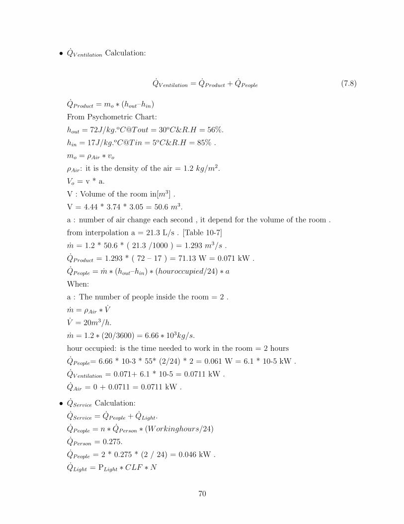
• QV entilation Calculation:
QV entilation = QProduct + QPeople (7.8)
QProduct = mo ∗ (hout–hin)
From Psychometric Chart:
hout = 72J/kg.oC@Tout = 30oC&R.H = 56%.
hin = 17J/kg.oC@Tin = 5oC&R.H = 85% .
mo = ρAir ∗ voρAir: it is the density of the air = 1.2 kg/m2.
Vo = v * a.
V : Volume of the room in[m3] .
V = 4.44 * 3.74 * 3.05 = 50.6 m3.
a : number of air change each second , it depend for the volume of the room .
from interpolation a = 21.3 L/s . [Table 10-7]
m = 1.2 * 50.6 * ( 21.3 /1000 ) = 1.293 m3/s .
QProduct = 1.293 * ( 72 – 17 ) = 71.13 W = 0.071 kW .
QPeople = m ∗ (hout–hin) ∗ (houroccupied/24) ∗ aWhen:
a : The number of people inside the room = 2 .
m = ρAir ∗ VV = 20m3/h.
m = 1.2 ∗ (20/3600) = 6.66 ∗ 103kg/s.
hour occupied: is the time needed to work in the room = 2 hours
QPeople= 6.66 * 10-3 * 55* (2/24) * 2 = 0.061 W = 6.1 * 10-5 kW .
QV entilation = 0.071+ 6.1 * 10-5 = 0.0711 kW .
QAir = 0 + 0.0711 = 0.0711 kW .
• QService Calculation:
QService = QPeople + QLight.
QPeople = n ∗ QPerson ∗ (Workinghours/24)
QPerson = 0.275.
QPeople = 2 * 0.275 * (2 / 24) = 0.046 kW .
QLight = PLight ∗ CLF ∗N
70

QLight= 24 W. CLF: Cooling Load Factor of Lighting = 0.88 .
N: Number of Lights
N = 2
QLight = 24 * 0.88 * 2 = 42.24 W = 0.0422 kW
QService = + 0.046 + 0.0422 = 0.088 KW .
• QRespiration Calculation:
QRespiration = m ∗ qRipsQRespiration : is the rate of respiration .
m : is the mass of the product in the room in [ kg ] .
qRips Rate of heat given off Breathing product .
qRips = 0.029 . [Table 10-12] .
QRespiration = 0.029 * 1000 = 29 W = 0.029 kW .
Consequently:
QTotal = 0.81 + 1.755+ 0.0711 +0.088+ 0.029 = 2.75 kW .
QTotal =2.75*F.S = 2.75*1.5 = 4.125 Kw
The following figure 7.8 for the cycle in PH diagram and the values of points in cyclefigure 7.7 from Cool pack
Figure 7.7: The values of points in cycle.
qe = h1–h5
= 400.073– 248.748 = 151.325 kJ/kg .qc = h2–h4
= 419.252 – 248.748 = 170.504 kJ/kg .Wc = h2–h1
= 419.252 – 400.073 = 19.179 WQe = mRqemR = Qe/qe = 4.125/151.315 = 0.02726kg/s.
71

Figure 7.8: The cycle in the PH diagram
72

Qc = mRqc=0.02726 *170.504=4.648 kW .P= mWc
=0.02726 *19.179= 0.5228 kW = 0.701086348 hp hp : horsepower [electric] .Coefficient of performance (cop) = qe / W = 151.315/19.179 = 7.889
7.1.3 Compressor selection
By Using BITZER-Software : compressor data sheet figure 7.9 & 7.10 below.
Figure 7.9: The cycle in the PH diagram
Figure 7.10: The cycle in the PH diagram
For more about data sheet go to appendix B
73

7.1.4 Condensers selection
By Using BITZER-SoftwareCondenser data sheet figure 7.11 & 7.12 & 7.12 below.
Figure 7.11: Condensing units.
Figure 7.12: Technical data.
74

Figure 7.13: Technical data.
7.2 Cooling Load Calculation for freezer
Using this law to find Cooling Load Calculation:Q = UA∆T eg 6.1.Q : Cooling Load in [ kW ] .U : Overall heat transfer coefficient in [W/m2.oC ] .U = 1
1hi
+Σ∆xiki
+ 1ho
hin : is the Inside Convection Coefficient 9.37 W/m2.oC .hout: is the Outside Convection Coefficient 22.7 W/m2.oC .K: is the thermal conductivity for material in [W/moC] .∆X: is the Thickness of the material in [m] .A: Surface area in [m2] .A=Length * Width.∆T : The difference in temperature [oC] .
1. External Wall:
∆T = Tsur − Tin∆T= 30–18=48
AExternalWall1 = 3.74 ∗ 3.05 = 11.4m2 .
75

QExternalWall1 = 0.58 * 48 * 11.4 = 0.317 kW.
2. Internal Wall1 :
∆T = TRoom − Tin= 28– -18 = 46 oC .
A = AInternalWall–ADoor
= (4.44 * 3.05 )
= 13.54m2.
A =AInternalWall − ADoor= (3.74 * 3.05) - 4
= 7.4m2 .
QInternalWall1 = 0.575 * 46 * 20.94 = 0.584 kW .
3. Internal Wall2 :
∆T = TRoom − Tin= 5– -18 = 23 oC .
A = AInternalWall2
= (4.44 * 3.05 )
= 13.54m2.
QInternalWall2 = 0.325 * 23 * 13.54 = 101W = 0.101 kW.
4. Ground :
∆T = TGround − Tin= 5– -18 = 23 oC .
A = AGround
= (4.44 * 3.74 )
= 16.6m2.
QGround = 0.399 * 23 * 16.6 = 0.153 kW .
5. Ceiling :
∆T = 28− Tin= 28- -18 = 46 oC .
A = ACeiling
= (4.44 * 3.74 )
= 16.6m2.
QCeiling = 0.444 * 46 * 16.6 = 0.339 kW .
76

6. Door :
∆T = TRoom − Tin= 28- -18 = 46 oC .
A = ADoor
= (2*2 )
= 4m2.
QDoor =0.631 * 46 * 4 = 0.116 kW .
Use this law to calculate cooling load for rooms:
QTotal = QEnvelope + QProduct + QAir + QService + QRespiration
For Refrigerator:• QEnvelope Calculation:
QEnvelope: heat gain from walls, doors, windows, floor and ceiling.
QEnvelope = Q1 + QSolar.
Q = QWall + QDoor + QFloor + QCeiling
QSolar = 0
QEnvelope = 0.685+0.47+0.339+0.116+0 = 1.61 kW .
• Q Product Calculation:
QProduct = Q∗2 + Q∗∗
2 + QPackaging
Q∗2 = mcp∆T .
When:
m = (mProduct / Time Cooling )
Time Cooling: Working Time Per a Day .
∆T = ∆Tsur = 30oC.
Q∗2 = 0.855 kW .
Q∗∗2 =(m/time)*∆h+ (m/time) ∗ cp ∗∆T
= (1000/11*3600)*47+ (1000/16*3600)*1.6*(0- -18)
=1.18 kW +0.5 kW = 1.68 kW
QPackaging = (mMaterial/T imeCooling) ∗ cp ∗∆T
Where: m Material = m * N .
m : is the mass of one pallet = 15 kg .
N: is the number of pallets in the room = 20.
m Material = 15 * 20 = 300 kg .
cp : is the Specific Heat for Pallet = 0.67 kJ/kg.K .
77

∆T = ∆Tsur = 30oC.
QPackaging = ( 300 / ( 4 * 16 * 3600 ) ) * 0.67 * 30 = 0.105 kW .
QProduct = 0.885+1.68+0.105 = 2.535 kW.
Table 7.8: product used.Product cp m m Q∗
2
Beef 1.59 120 0.002083 0.099375Chicken 1.63 120 0.002083 0.101875Clams 1.51 40 0.000694 0.031458Codfish 1.63 70 0.001215 0.059427Halibut 1.67 80 0.001389 0.069583Ice cream 1.67 30 0.000521 0.026094lamp 1.55 50 0.000868 0.040365Oysters 1.72 60 0.001042 0.05375Reindeer 1.55 40 0.000694 0.032292salmon 1.55 80 0.001389 0.064583Sausage 1.34 100 0.001736 0.069792sword fish 1.67 80 0.001389 0.069583tripe 1.72 50 0.000868 0.044792veal 1.59 50 0.000868 0.041406white fish 1.63 60 0.001042 0.050938Σ 1.653281
• QAir Calculation:
QAir = QInfiltration + QV entilation
QInfiltration = 0 kW.
QV entilation = QProduct + QPeople
QProduct = m ∗ (hout–hin)
QProduct = 1.293 * (72 – 10) = 80.16 W = 0.08 kW .
QPeople = m ∗ (hout–hin) ∗ (houroccupied/24) ∗ aQPeople = 6.66 * 10-3 * 55* (2/24) * 2
QPeople = 0.061 W = 6.1 * 10-5 kW.
QV entilation = 0.08+ 6.1 * 10-5 = 0.08 kW.
QAir = 0 + 0.08 = 0.08 kW.
• QService Calculation:
QService = QPeople + QLight.
QPeople = n ∗ QPerson ∗ (Workinghours/24)
QPerson = 0.275. [Table 10-14] .
78

QPeople = 2 * 0.275 * (2 / 24) = 0.046 kW .
QLight = PLight * CLF * N
QLight= 24 W.
CLF: Cooling Load Factor of Lighting = 0.88 .
N: Number of Lights
N = 2
QLight = 24 * 0.88 * 2 = 42.24 W = 0.0422 kW
QService = + 0.046 + 0.0422 = 0.088 KW .
• QRespiration Calculation:
QRespiration = m ∗ qRipsQRespiration : is the rate of respiration .
m : is the mass of the product in the room in [ kg ] .
qRips Rate of heat given off Breathing product .
qRips = 0.029 . [Table 10-12] .
QRespiration = 0.029 * 1000 = 29 W = 0.029 kW .
Consequently:
QTotal = 1.61 + 2.535+ 0.08 +0.088+ 0.029 = 4.35 kW .
QTotal =4.35 * F.S = 4.35 * 1.5 = 6.5 kW.
The following figure 7.15 for the cycle in PH diagram and the values of points in cyclefigure 7.14 from Cool pack
Figure 7.14: The values of points in cycle.
qe = h1–h5
= 357.822 – 254.208 = 103.14 kJ/kg .qc = h2–h4
79

Figure 7.15: The cycle in the PH diagram
80

qc = 389.924 – 254.208 = 135.716 kJ/kg .Wc = h2–h1
Wc = 389.924 – 357.822 = 32.102 kJ/kg .Qe = mRqemR = Qe/qe = 6.5/103.14 = 0.063kg/s.Qc = mRqcQc =0.063 * 135.716=8.55 kW .P= mWc
=0.063 * 32.102= 2.02 kW = 2.7 hP hP : horsepower [electric] .Coefficient of performance (cop) = qe / W = 103.14/32.102 = 3.212
7.2.1 Compressor selection
By Using BITZER-Software : compressor data sheet figure 7.16 below.
Figure 7.16: The compressor data sheet
For more about data sheet go to appendix B
7.2.2 Condensers selection
By Using BITZER-Software
81

Condenser data sheet figure 7.17 below.
Figure 7.17: Condenser data sheet.
82

References
1. Ronald L.Howell, Principles of Heating Ventilating and Air Conditioning 6th edition,ASHRAE, USA, 2009.
2. Health Technical Memorandum,Medical gas pipeline systems The Design, installation,validation and verification, USA,2002.
3. M. A. A. M. Ashamed, Heating and Air Conditioning for Residential Buildings, Na-tional Library Department, Jordan, 2007.
4. J. F. Krieger, Handbook of Heating, Ventilation, and Air Conditioning, Boca Raton,CRC.Press LLC, Florida, 2001.
5. Mohammad A. Hammed, Heating and Air conditioning 3rd edition, Jordan, 1996.
6. Brain L.Olsen,Plumbing System 2nd edition,Missouri Group, USA, 1982.
7. Dennis Kubicki,FIRE PROTECTION DESIGN CRITERIA 3rd edition, Washington,D.C,1982.
8. https : //rcwapp.xyleminc.com/fpselect.asp .
9. https://engineeringtoolbox.com .
10. http : //www.healthyheating.com/Definitions/Operative−temperature.htm.WHx−C1MrLIU .
11. https://www.aspe.org/sites/default/files/webfm/ArchivedIssues/2006/20060102/ContinuingEdMedGasVac.pdf.
83

Appendix (A)
Bill of Quantities
84

Table 7.9: Bill of quantities.
Item No. Description Unit Qty. Unit Rate1.0 Mechanical works
In the list of recommended makes, out of twoor three makes mentioned in the list, only1st. Make shall be preferred for use, unlessotherwise specified in BOQ.However if non-availability or any other tech-nical reason, the alternative make is allowed.This section shall be read in conjunction withgeneral and particular mechanical technicalspecifications, mechanical drawings, adden-dums and invitation to bid conditions exceptwhere otherwise indicated.The unit price for all items in this sectionshall include supplying, installing, testing,and commissioning of mechanical works andmaterials, unless otherwise specifically men-tioned or instructed by engineer.All civil and finishing works related to theconcerned items shall be included in the unitprice.Preparing of coordinated shop drawing andsubmitting to the approval of the supervisionengineer, coordination with other activities,material storage, removing away from sitethe remnant of mechanical works and han-dling over the mechanical works to local me-chanical auth.Flexible PVC suitable size conduits andadaptors to be used for connecting motorsto power supply.Electrical cables up to mechanical equip-ment, to be supplied, installed connecting tomains side, testing and to be commissionedby electrical contractor, just cables termina-tion to mechanical equipment to be carriedon by mechanical contractor.
1.1 Waste and drainage system
Continued on next page
85

Table 7.9 – Continued from previous pageItem No. Description Unit Qty. Unit Rate
1.1.1 Vertical and horizontal UPVC pipeSupply, install UPVC pipes and fittings sim-ilar to (Royal) or E.A. The rate shall includeall needed connections and all types of fit-tings caps, all done according to drawings,specifications and the approval of the super-vision engineer.
A. Dia 2” ML 180B. Dia 4” ML 250
1.1.2 Floor trap and clean outSupply, installation, and commissioning offloor trap melding threaded (15*15) cmchrome plated cover UPVC red siphon (in-cluding junction box). And connected it withvertical pipes the price including rings fit-tings and whatever needed to complete thejob as located on drawing specifications andapproval of supervision engineer.
A. Floor trap size 4” diameter No. 28B. Floor drain size 4/2” diameter No. 21C. Clean outs 4” but with closed type cover,
size (11*11) cm.No. 40
D. Clean outs 6” but with closed type cover. No. 21.1.3 Supply, installation, and commissioning all
pipes and fittings to and overflow storagetank in basement the price includes manholeinside boiler room and whatever needed tocomplete the job as located on drawing spec-ifications and approval of supervision engi-neer.
Job 1
1.1.4 Supply install and test UPC (UPA) or E.A.external drainageAll rain pipes and fittings including con-nection excavation covering with layer 20cm sand around the pipe and back fillingas shown in drawings and specifications ap-proval of supervisor engineer.
A. Size 6 inch diameter ML 40
Continued on next page
86

Table 7.9 – Continued from previous pageItem No. Description Unit Qty. Unit Rate
1.1.5 Supply and install PRE-CAST concretemanholes of 15 cm thick walls and base withheavy duty cast iron covers and frames of 25tons load strength with all necessary excava-tion back filling as specified to the requireddepth with steps of galvanized pipe of 1/2”benching and connecting it to main city man-holes as shown in drawing and in accordanceto specifications and approval engineers.
A. Size 60 cm (inside diameter) No. 21.1.6 Supply and install concrete manholes of 15
cm thick walls and base with Medium dutyconcrete and frames of 8 tons load strengthwith all necessary excavation back filling asspecified to the required depth with steps ofgalvanized pipe of 1/2” benching and con-necting it to main city manholes as shown indrawing and in accordance to specificationsand approval engineers.
A. Size 60 cm (inside diameter) No. 12B. Size 80 cm (inside diameter) No. 18C. Size 100 cm (inside diameter) No. 9
1.1.7 Supply, install and test drain water and rainconcrete channel with low carbon steel frameand mesh cover as shown in drawing and inaccordance to specifications and approval en-gineers.
A. Width = 25 cm, h = 30 cm No. 2B. Ditto but with stainless steel frame and mesh
cover.No. 3
1.1.8 HVAC Drain PipingSupply, install and test UPVC heavy classdrain piping for SPLIT UNITS and Cassettetype units for the following diameters of thepipes. The pipes shall be insulated with6mm thick nitrile rubber and in accordanceto specifications and approval engineers.
A. 25 mm Rm m 40B. 32 mm Rm m 401.2 Domestic hot and cold water system
Continued on next page
87

Table 7.9 – Continued from previous pageItem No. Description Unit Qty. Unit Rate
1.2.1 Main water supplySupply and install galvanized steel main wa-ter pipes 2” with asphalt protection (factorycovered) which will take from the main lineof the city 2”, with all necessary fitting e.g.elbow tee union stop valves non return valveand whatever needed to complete the joband all are of approved quality pipes are tobe piped and laid underground through 4”PVC pipe from main supply to water stor-age tank, price shall include piping with allfitting, water meter, steel box excavation in-sulation with sand back filling disposal of re-mained excavated soil and charges for con-nection with main water supply all are ac-cording to PWA and approval of supervisorengineer.
L.S 1
1.2.2 Supply and install galvanized pipes mediumclass for domestic cold water, hot water andhot water return, the work includes all fit-tings, valves, required flow direction signs,TOLGO type hangers, all required fittings,the prices includes vidoflex 13 mm for hotwater pipes and hot water return.
A. Dia 3/4” ML 110B. Dia 1” ML 60C. Dia 11/4” ML 40D. Dia 11/2” ML 20E. Dia 2” ML 35
Continued on next page
88

Table 7.9 – Continued from previous pageItem No. Description Unit Qty. Unit Rate
1.2.3 Supply and install hot and water collectorstype GIACOMINI or E.A. price include allthe supplying and installing 16 mm PEXplastic pipes with its 22 mm plastic conduitsto be connected from the copper collectorsopenings up to location of sanitary fixturesoutlets according to plans and engineers in-structions, with all required hangers (typeGIACOMINI) and support, air vent, shut-off valves on the collectors outlets, shut- offvalve each collector must have main valve atthe entrance of the collector the price includemetallic painted steel cabinet of approvedquality, including cover with double doors fordomestic water collectors. Job as located ondrawing specification and approval of super-visor engineer.
A. Dia 3/4” EYE 262.0 HVAC System :
Supply of new factory supplied air cooledVariable Refrigerant Flow System. Supplyof variable Refrigerant Flow modular typeair conditioning system complete with indoor& outdoor units with individual corded con-troller as per the following capaicties of theIDU and ODU.
2.1 Outdoor UnitsModular type outdoor units equipped withhighly efficient scroll compressors with all in-verter type compressor(s) only, special acrylprecoated heat exchanger, low noise con-denser fan, pre coated fin type heat exchang-ers. The outdoor and indoor units shall beintegrated with special super wiring systemwith a central monitoring remote controllerinto one common wiring. All refnet pipingsystem shall be imported. Refrigerant shouldbe R410A. All structural frame work plat-forms required shall be of HVAC vendor asper site conditions.
A. 48 HP No. 1
Continued on next page
89

Table 7.9 – Continued from previous pageItem No. Description Unit Qty. Unit Rate
B. 46 HP No. 1C. 20 HP No. 12.2 Indoor Units for above mentioned
outdoor unit2.2.1 Ceiling mounted four way air discharge cas-
sette indoor units with compact cooling coil,electronic expansion valve and multi speedfan motor, The blower shall be dynami-cally balanced and designed for silent oper-ation, the filters shall be Plasma and syn-thetic washable media type arranged for con-venient cleaning and replacement, built indrain pump, the drain pan shall be fabricatedout of heavy sheet steel insulated with 6mmexpanded polyethylene sheet.
A. 11.2 kW No. 15B. 12.8 kW No. 2C. 14 kW No. 8
2.2.2 High wall mounted units with plasma andsynthetic washable filter.
A. 5.6 kW No. 17B. 7.1 17kW No. 102.3 Wired Remote controls for all the Hi-wall
and Cassette type units which shall be sleekand self diagnostic type.
No.
2.4 Simple Central Controller Unit capable ofcontrolling all the Indoor and outdoor units
No.
2.5 Refrigerant PipingSupply and installation of Refrigerant Cop-per piping insulated with Nitrile Rub-ber Tubular Insulation with covered withpolyshield
A. 54.1 mm with 19 mm thick insulation M 120B. 41.3 mm with 19 mm thick insulation M 120C. 34.9 mm with 19 mm thick insulation M 70D. 28.6 mm with 19 mm thick insulation M 70E. 25.4 mm with 19 mm thick insulation M 65F. 22.2 mm with 13 mm thick insulation M 65G. 19.1 mm with 13 mm thick insulation M 35H. 15.9 mm with 10 mm thick insulation M 45I. 12.7 mm with 10 mm thick insulation M 160
Continued on next page
90

Table 7.9 – Continued from previous pageItem No. Description Unit Qty. Unit Rate
J. 9.5 mm with 8 mm thick insulation M 60K. 6.4 mm with 8 mm thick insulation M 1552.6 Electrical Cabling
Armoured copper cables from the isolator tothe units at terrace. (Power Cable) ( thesize of the cabel to selected by the vendoras per the manufacturer standard and to beapproved by the consulanat.
L.S
2.7 NotesA. All civil works pertaining to Air-conditioning
like breaking, making, painting of walls, glassetc. as required as per site conditions.
B. Supply and installation all of the items men-tioned in the previous must be in accordanceto specifications and approval engineers.
C. Catalogues of all equipments shall be en-closed with Compressor rating charts.
D. Incoming Power supply near indoor unit willbe provided by other agencies.
E. Taxes to be included in the price of equip-ments /accessories...
3.2 fire extinguisher cylinder:Supply and install the CO2 ” 3kg” , HCFC”3kg”,and Wet chemical ”3kg”.
A. CO2 fire extinguisher cylinder No 10B. HCFC fire extinguisher cylinder No 35C. Wet fire extinguisher cylinder No 3
91

92

Appendix (B)
93
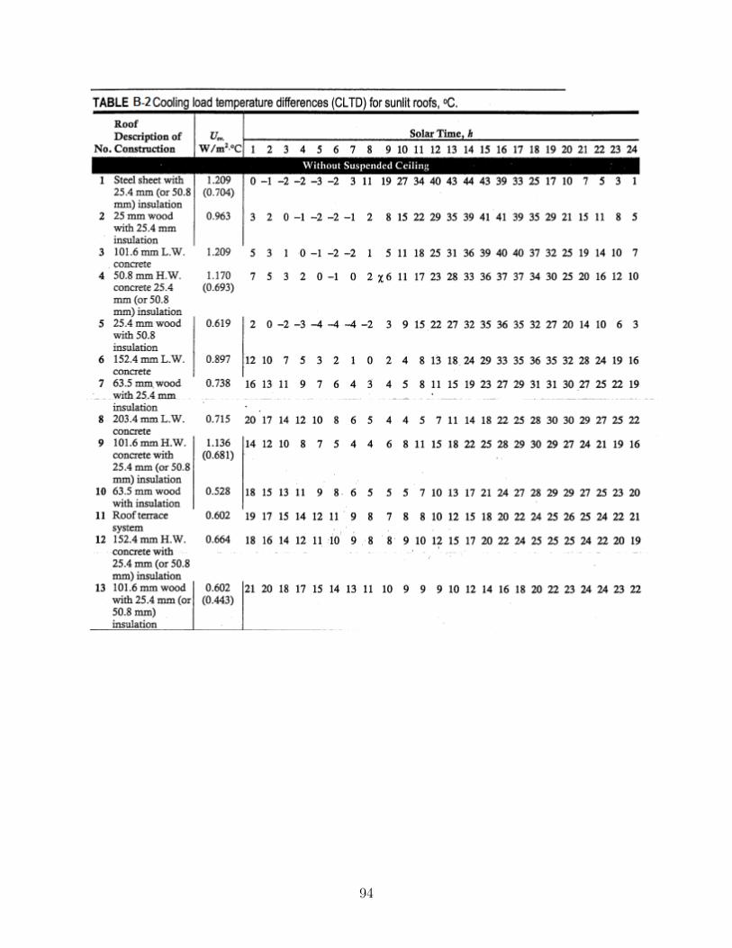
94

95

96

97

98

99

100

101

102

103

104

105

106

107

108

109

110

111

112

113

114
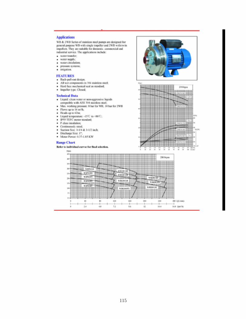
115

116

117

118

119
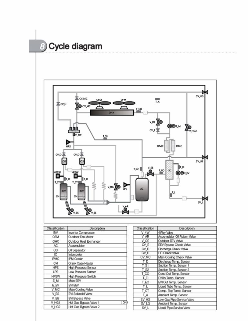
120

121

122

123

124

125

126