College of Engineering - Kansas Department of … Program College of Engineering Phase IV...
89
Architectural Program Kansas State University College of Engineering Phase IV Expansion November 1, 2012 Prepared by: BG Architecture a division of BG Consultants, Inc. 4806 Vue Du Lac Place Manhattan KS 66503
Transcript of College of Engineering - Kansas Department of … Program College of Engineering Phase IV...
Architectural Program
Kansas State University
College of Engineering Phase IV Expansion
November 1, 2012
Prepared by:
BG Architecture
a division of BG Consultants, Inc. 4806 Vue Du Lac Place Manhattan KS 66503

Architectural Program College of Engineering Phase IV
Programming Committee John English Dean, College of Engineering
Gary Clark Associate Dean for Academics and Administration, College of Engineering
Noel Schulz Associate Dean for Research and Graduate Programs, College of Engineering
David Fritchen Department Head, Architectural Engineering and Construction Science; College of Engineering Project Coordinator
Joseph P. Harner Department Head, Biological and Agricultural Engineering
James H. Edgar Department Head, Chemical Engineering
Alok Bhandari Department Head, Civil Engineering
Robert J. Peterman Professor, Civil Engineering
Gurdip Singh Department Head, Computing and Information Sciences
Don Gruenbacher Department Head, Electrical and Computer Engineering
Bradley A. Kramer Department Head, Industrial and Manufacturing Systems Engineering
Don Fenton Department Head, Mechanical and Nuclear Engineering A. Abe Fattaey Director of Campus Planning and Facility Management, Division of Facilities David McMullen Assistant University Architect, Division of Facilities Annette Rohde Project Coordinator, Division of Facilities
Table of Contents
Introduction .......................................... 1 1.1 Project Overview and Objectives ........... 1-1 1.2 Keeping Kansas Competitive Engineering 1.3 Initiative .................................................. 1-1 1.3 Current Conditions and Pressing Demand ........................................................ 1-1 1.4 Site Map ................................................. 1-3
Considerations ..................................... 2 2.1 Principle Considerations ......................... 2-1 2.2 College of Engineering General Expansion Needs ........................................................... 2-1 2.3 Department Specific Needs .................... 2-3
Program Space ..................................... 3 3.1 Numeric Program ................................... 3-1 3.2 Allocated Budget .................................... 3-6
Facility Design ...................................... 4 4.1 Architectural Design ............................... 4-1 4.2 Mechanical and Systems Design ........... 4-2
Proposed Conceptual Plans ................ 5 Expansion Diagrams .................................... 5-2 Expansion Plans ........................................... 5-5 Exterior Rendering ...................................... 5-11 Interior Rendering of Hospitality Center ..... 5-12
Appendixes ....................................... A-F Appendix A, Expansion Summary ................A-1 Appendix B, Space Requirements ...............B-1 Appendix C, Space Diagrams ..................... C-1 Appendix D, Definitions ............................... D-1 Appendix E, Site Evaluations .......................E-1 Appendix F, Planning Meeting Minutes ........ F-1

Architectural Program College of Engineering Phase IV
BG Architecture | November 1, 2012 Page 1-1
Introduction 1.1 Project Overview and Objectives Kansas State University engaged BG Architecture a division of BG Consultants to conduct existing conditions analysis and programming for building expansion to meet the growing needs of the College of Engineering. This work for programming and space needs assessment is the initial stage of the College of Engineering Phase IV Expansion. Together with College of Engineering Dean John English, Engineering Department Heads, and the Facilities Planning Group, BG developed this program with written description of key considerations, numeric and written space program, conceptual expansion plans, cost estimate, and supporting data. This program is an evolution of an initial programming effort which evaluated the eight departments within the College of Engineering for current space usage and for projected future space requirements to meet the projected growth. At the time of the initial general programming effort, it was unknown which department or departments within the College would occupy the new space. Computing and Information Sciences, Electrical and Computer Engineering, and Civil Engineering departments are designated to occupy the new space. In addition, space has been provided to support team instruction, space for student competition teams, and opportunity to showcase both instructional and research areas. Some of the key objectives that were identified over the course of the study included sighting of the expansion, connectivity of the expansion for continuity of building circulation and accesses, appropriate allocation of spaces for each department, daylighting, designing space for collaboration and integrated culture. Other major drivers of the program solution were the limitations of the site including limited buildable space, existing site utilities, access requirements, universal accessibility, and campus planning objectives. This report includes a description of the need for additional space for the College of Engineering, the basis of the architectural program spaces, numeric program, allocated budget, and facility design criteria. 1.2 Keeping Kansas Competitive Engineering Initiative In the spring of 2011, the State of Kansas passed the ‘Keeping Kansas Competitive Engineering Initiative” that will provide $3.5 million per year in state funds to each of the state’s professional engineering programs, with a dollar-for-dollar match provided by the universities to ensure Kansas businesses have access to the engineering talent they need to fuel economic growth. The colleges will use this investment to implement plans to increase engineering graduates to 1,365 by 2021. Kansas State University will meet the challenges of this initiative by expanding its current engineering facility to meet the demand of an additional 750 students over ten years. To accommodate these additional students, the College of Engineering will increase its educational capability by adding to the existing College of Engineering complex. 1.3 Current Conditions and Pressing Demand The current College of Engineering complex is made up of three major buildings or wings: Durland Hall (originally constructed in 1976), Rathbone Hall (originally constructed in 1982), and Fiedler Hall (originally constructed in 2000) and currently contains 267,040 square feet.

Architectural Program College of Engineering Phase IV
BG Architecture | November 1, 2012 Page 1-2
Figure 1 - College of Engineering Complex
Durland and Rathbone Hall were the first two phases of the Durland-Rathbone-Fiedler engineering complex extending over the old football practice field. Together they house the Dean’s Office for the College of Engineering and the Departments of Electrical and Computer Engineering, Industrial and Manufacturing Systems Engineering, Mechanical and Nuclear Engineering, Chemical Engineering, and Civil Engineering. Fiedler Hall is the third phase of the engineering complex and houses the Department of Civil Engineering, engineering library and auditoriums, meeting rooms and computer labs for the College of Engineering (COE). The COE is at capacity in view of its facilities. Phase IV Expansion will require additional building area to supplement the existing infrastructure and meet the growth of an additional 750 students over ten years. Additionally, support for increased student populations will necessitate an increase in faculty and staff to retain current undergraduate student-to-faculty ratios of 25:1. Need for an increase of 30 tenure-track faculty is anticipated. In light of increases in student body and faculty, additional staff support will be required. Organizing principles guiding the infrastructure growth should address the following needs as priorities: educational space for COE prominent design teams (identified in this program as Space for Competition), working/teaching laboratory environments facilitating team instruction, collaborative research space, and dedicated space for college-level student organizations and student recruitment and retention activities. Additional factors should consider vehicular and pedestrian circulation from main campus and Denison Avenue.

Architectural Program College of Engineering Phase IV
BG Architecture | November 1, 2012 Page 1-3
Figure 2 – Site Context Map
1.4 Site Map The College of Engineering Complex is located on the southwest edge of the campus on the corner of College Heights Road and Denison Avenue. Located adjacent to Denison Avenue, the complex is highly visible and as such opportunity for addressing the issue of public front exists. Additional considerations should be given to storm water drainage, utilities and public safety.

Architectural Program | College of Engineering Phase IV Expansion
BG Architecture | November 1, 2012 Page 2-1
Considerations 2.1 Principle Considerations The College of Engineering serves demand for engineers and computer scientists. These professionals contribute to employment in a broad skilled workforce contributing to the diversity and vitality of Kansas and industries nationally and internationally. Space for Team Instruction New teaching facilities are needed to accommodate the expected increased enrollment and to maintain the level of student involvement. Space for Student Competition Teams In addition to classroom instruction, the ability to put into practice the concepts learned in the classroom is the prime goal of the competition space. Students gain knowledge of engineered solutions, processes and products by direct application. This “hands on” process gives the students the technical and practical experience needed to be competitive in their future professions In addition to the tangible benefits, the competition/team spaces are a benefit to the college and help promote its culture and, as a result, its ability to attract potential students. Therefore, the competition spaces should be both accessible and visible to the engineering college community as well as the university as a whole. Space for Collaboration Much like the ability to work in teams in the classroom environment, the ability for both students and professionals to work in collaborative environments, specifically research areas, is a very important component of the current engineering college leadership. The opportunity to pool resources as well as expertise helps take the research to the next level and enables the college of engineering to stay a premiere institution in the Midwest and the country. By providing the college with extra lab/collaborative research rooms, the college will be in an excellent position to attract both students and educators over the next decade. Integrated Culture All three of the items described above: Space for Team Instruction, Space for Student Competition Teams, and Space for Collaboration contribute to enhancing the “Integrated Culture” of the College of Engineering. The architecture of the spaces listed above, in addition to the rest of the building, must encourage interaction among students, staff and educators. Such spaces should be interwoven within the new construction to create opportunities for impromptu and spontaneous discussion between students and faculty. 2.2 College of Engineering General Expansion Needs As the College of Engineering meets projected growth space will be required to meet general college instruction, as well as dedicated space for student competition team work, student alumni and visitor welcome and other areas for college-level student organizations and student recruitment and retention activities. Areas affected by the inclusion of new space will be relocated and incorporated into the project. One space anticipated for relocation is the existing Serpan Lobby. Considerations for relocation should

Architectural Program | College of Engineering Phase IV Expansion
BG Architecture | November 1, 2012 Page 2-2
(a) Cluster Style Classroom
(b) Harvard Style Classroom
Figure 3 – Classroom Styles
take into account existing square footage, use, and accessibility so that when relocated the space is equally celebrated. General Academic Spaces New teaching facilities are needed to accommodate the expected increased enrollment and to maintain the current level of student involvement. Currently, most of the existing classrooms are based on a flat floor/individual instruction model. These types of classrooms, although providing flexible seating
arrangements, are not able to accommodate larger class sizes or various teaching methods. The engineering professions demand that students get experience with working in teams and new team-focused classrooms are needed to maintain and improve the level of student participation and integration. These new types of classrooms require a different floor plan configuration and are difficult to achieve in the current building footprints. In addition, increasing demand for Distance Education is required to be integrated as a central part of at least one classroom cluster. This serves as a basis for extending the quality of education provided by the College of Engineering beyond Campus boundaries. One example is the Cluster Style Classroom. The Cluster Style Classroom serves a dual purpose: allowing both lecture style instruction while allowing a class to break into smaller discussion groups within the same room. The Cluster Style Classroom gives the instructor advantages in teaching styles. Another example is the Harvard Style Classroom. The Harvard Style Classroom is a tiered or sloped floor room and is generally used when class sizes are large and exceed the point where all class participants can see each other clearly. Due to excellent sight and acoustic lines and the horseshoe arrangement, Harvard Style Classrooms in excess of 100 seats can still feel intimate and allow a level of interaction within a class not possible in a flat-floor room. General Academic Support New facilities are needed to successfully mitigate dedicated space for college-level student organizations and student recruitment and retention activities. Also,
trends towards enhanced casual discussions and small group collaboration require thoughtful consideration of various sizes of spaces. Space for informal gatherings should be encouraged throughout the expansion. Gathering space for team, instructor, or faculty work sessions should be distributed throughout the new construction providing optimum access for scheduled events. Support spaces for these areas should be conveniently located.

Architectural Program | College of Engineering Phase IV Expansion
BG Architecture | November 1, 2012 Page 2-3
General Support New project facilities for the colleges prominent design teams (such as SAE Formula car, mini baja car, quarter-scale tractor, chemical engineering car, concrete canoe, steel bridge, etc) are needed. These spaces should be community celebrated and opportunity for showcasing them is to be explored. Additionally, these areas should be organized to permit the greatest flexibility to meet ever changing project needs. Supporting spaces for these areas should be conveniently located. Facility Support In addition to dedicated space for instruction and research, required allocation for physical access to floors and areas that support the buildings cleaning and public hygiene functions are to be organized logistically to support the building program. Additionally, space to house mechanical equipment, utility services, and shaft areas are to be located with considerations for flexibility and future building adaptability to changing demands in use and infrastructure. 2.3 Department Specific Needs The following departments are allocated space within the new expansion: Civil Engineering, Computer and Information Sciences, and Electrical and Computer Engineering. Additional research space for Civil Engineering is programmed, as well as complete re-location of Computer and Information Sciences and Electrical and Computer Engineering. Existing space will be vacated by Electrical and Computer Engineer in Rathbone. Evaluation and re-assignment of this vacated area will not be a part of this project. Departmental Suite New space for department administration is required. Serving as the head of the department this space is intended to provide a sense of identity for each department and to support discipline recruitment, retention, and staff support. Successful designs of these spaces will accommodate the frequency of alumni, student, staff and other professionals which visit the Department Head and other administrators. Academic Support New facilities are required to meet the growth of faculty. Such spaces should reflect adjacencies of like functions and uses. Support spaces for faculty will be needed to compliment their activities. These areas support the academic functions of the College. System Administration Space for system administrators and support areas for department computer information and telecommunications systems are needed. These areas should be located near auxiliary support systems and services to help keep all department systems activities operational. Instructional Spaces Teaching facilities are needed. Such spaces should be designed around contemporary models for instruction and should not only maintain but improve the level of student engagement. These spaces should facilitate interactive discussion and permit collaborative project development. Traditional classrooms are long, flat and narrow. Current trends incorporate spaces that are wider and more adaptable. Considerations should be given for integrated technology.

Architectural Program | College of Engineering Phase IV Expansion
BG Architecture | November 1, 2012 Page 2-4
Research Spaces Research facilities are needed. Used for laboratory experimentation, research and training in research methods, these spaces are to be configured to support the limits of instructional and research activities performed for each. To the extent possible, these spaces should be reconfigurable to meet ever changing demands for programs. Flex and Facility Support New facilities are needed to house department support space in addition, to space adaptable to future department needs. Flex space is unassigned space dedicated for growing demand and may be assigned use not currently allocated. Additionally, this includes support space auxiliary to department uses.

Architectural Program | College of Engineering Phase IV Expansion
BG Architecture | November 1, 2012 Page 3-1
Program Space The following spaces are to be integrated in the design of the new facility and in light of the design considerations established in this document. Spaces dedicated to each department will be indicated as follows: Civil Engineering (CE), Computer and Information Sciences (CIS), and Electrical and Computer Engineering (ECE). All other spaces not otherwise indicated are intended for general College of Engineering use and assignment. The proposed addition to the Engineering complex will be composed of the following spaces: 3.1 Numeric Program
Qty Capacity SF per space
TOTAL NASF
SF per occupant
Gross Factor
TOTAL GSF TOTALS
GENERAL COLLEGE OF ENGINEERING ALLOCATED SPACE
GENERAL ACADEMIC SPACES 12,773
Large College Classroom [110] 1 75 1800 1800 24 1.5 2700
Large Lecture Hall [110] 1 250 4475 4475 18 1.5 6713
Distance Learning Recording Room (VE) [530] 1 4 350 350 100 1.5 525
College Classroom [110] 2 30 945 1890 31 1.5 2835
GENERAL ACADEMIC SUPPORT 10,898
Hospitality Center
Reception Area/Lounge [650] 1 47 700 700 15 1.5 1050
Meeting Room [680] 1 50 750 750 15 1.5 1125
Large Conference Room [680] 1 60 1850 1850 31 1.5 2775
Medium Conference Room [350] 1 40 1240 1240 31 1.5 1860
Small Conference Room [350] 1 20 620 620 31 1.5 930
Catering Kitchen [685] 1 2 315 315 200 1.5 473
Seminar [410] 2 15 530 1060 35 1.5 1590
Common Lounge (C L) [410] 2 24 365 730 15 1.5 1095
GENERAL SUPPORT 12750
Competition Spaces [250] 5 24 1200 6000 50 1.75 10,500
Student Shop [250] 1 15 750 750 50 1.5 1125
Central Support Space [755] 1 4 750 750 200 1.5 1125

Architectural Program | College of Engineering Phase IV Expansion
BG Architecture | November 1, 2012 Page 3-2
Qty Capacity SF per space
TOTAL NASF
SF per occupant
Gross Factor
TOTAL GSF TOTALS
FACILITY SUPPORT The following areas are ancillary and included in the Total GSF
IT Support Room (IT) [036] Provide (1) 25 square foot room per floor
Departmental IT Support (IT Supp) [036] Provide (1) 100 square foot room per department
Lactation Room (Lac) [590] Provide (1) 115 square foot room per facility. May be multiple spaces
Custodial Rooms (JC) [021] Provide a minimum of (1) per floor
Restrooms (R) [023] Provide as per Code Requirements
Elevator (E) [012] Provide (1) elevator accessible to all floors and roof. Elevator shall be oversized to serve both service and passengers
Exterior Loading Dock Provide (1) ramped loading dock to accommodate delivery by trailers, trucks and vans
CIVIL ENGINEERING ALLOCATED SPACE
ACADEMIC SUPPORT (CE) 630
Faculty Office (FO) [310] 3 1 140 420 100 1.5 630
RESEARCH SPACES (CE) 7936
Structures Lab [250] 1 80 4000 4000 50 1.6 6400
Insulated Pump Room [255] 1 1 240 240 300 1.6 384
Instrumentation and Calibration Room [255] 1 10 480 480 50 1.6 768
Control Room [255] 1 12 240 240 20 1.6 384
FLEX AND FACILITY SUPPORT (CE) The following areas are exterior and not included in the Total GSF
Exterior Wash Pit Provide (1) 100 square foot outdoor area for cleaning equipment
COMPUTER AND INFORMATION SCIENCES ALLOCATED SPACE
DEPARTMENTAL SUITE (CIS) 2220
Reception Office/Waiting [310] 1 4 440 440 100 1.5 660
Department Head Office [310] 1 3 260 260 100 1.5 390
Staff Office [310] 3 1 140 420 100 1.5 630
Meeting Area [350] 1 8 120 120 15 1.5 180
Copy Area / Break Room [315] 1 2 160 160 100 1.5 240
Storage (S) [315] 1 1 80 80 100 1.5 120
Architectural Program | College of Engineering Phase IV Expansion
BG Architecture | November 1, 2012 Page 3-3
Qty Capacity SF per space
TOTAL NASF
SF per occupant
Gross Factor
TOTAL GSF TOTALS
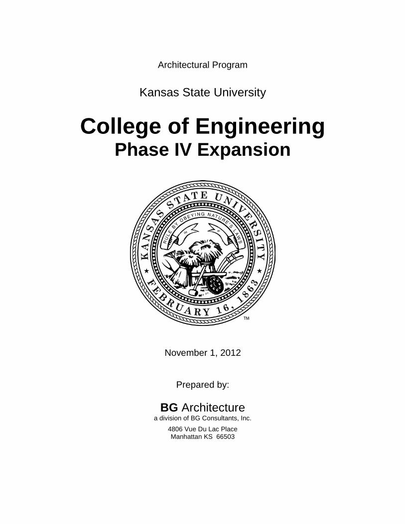
ACADEMIC SUPPORT (CIS) 5850
Department Lounge [315] 1 27 400 400 15 1.5 600
Faculty Office (FO) [310] 25 1 140 3500 100 1.5 5250
SYSTEM ADMINISTRATION (CIS) 1005
System Administrator Office (SAO) [310] 2 1 140 280 100 1.5 420
Technician Office (Tech) [310] 1 1 140 140 100 1.5 210
Storage/Hardware [715] 1 1 250 250 300 1.5 375
INSTRUCTIONAL SPACES (CIS) 5706
General Teaching Lab [210] 1 39 1200 1200 31 1.5 1800
Specialized Teaching Lab [210] 1 32 1004 1004 31 1.5 1506
Teaching Labs [210] 2 26 800 1600 31 1.5 2400
RESEARCH SPACES (CIS) 8480
Robotics Lab [250] 1 16 500 500 31 1.6 800
Security Lab [250] 1 16 500 500 31 1.6 800
KDD Lab [250] 1 10 300 300 31 1.6 480
High Assurance Lab [250] 1 32 1000 1000 31 1.6 1600
Kedzie Mutli_Agent Robotics Lab [250] 1 26 800 800 31 1.6 1280
GK-12/Embedded Systems Lab [250] 1 19 600 600 31 1.6 960
Bioinformatics Lab [250] 1 13 400 400 31 1.6 640
Cyber Defense Lab [250] 1 39 1200 1200 31 1.6 1920
FLEX AND FACILITY SUPPORT 4500
Data Center [710] 1 5 1500 1500 300 1.5 2250
Program Adaptable [070] 1 48 1500 1500 31 1.5 2250
ELECTRICAL AND COMPUTER ENGINEERING ALLOCATED SPACE
DEPARTMENTAL SUITE (ECE) 2730
Reception Office/Waiting [310] 1 4 440 440 100 1.5 660
Department Head Office [310] 1 3 260 260 100 1.5 390
Architectural Program | College of Engineering Phase IV Expansion
BG Architecture | November 1, 2012 Page 3-4
Qty Capacity SF per space
TOTAL NASF
SF per occupant
Gross Factor
TOTAL GSF TOTALS
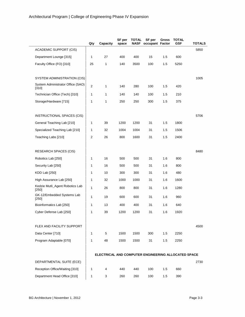
Project Coordinator Office [310] 1 2 160 160 100 1.5 240
Staff Office [310] 3 1 140 420 100 1.5 630
Advisors Office [310] 1 2 160 160 100 1.5 240
Copy Area / Break Room [315] 1 2 180 180 100 1.5 270
Storage (S) [315] 1 1 80 80 100 1.5 120
Meeting Area [350] 1 8 120 120 15 1.5 180
ACADEMIC SUPPORT (ECE) 5640
Department Lounge [315] 1 27 400 400 15 1.5 600
Faculty Office (FO) [310] 24 1 140 3360 100 1.5 5040
SYSTEM ADMINISTRATION (ECE) 675
System Administrator / Student Administrator Office [310] 1 3 250 250 100 1.5 375
Storage/Hardware [315] 1 1 200 200 300 1.5 300
INSTRUCTIONAL SPACES (ECE) 6660
Computer Lab [210] 1 24 740 740 31 1.5 1110
Digital Systems Lab [210] 1 24 740 740 31 1.5 1110
Microcontrollers Lab [210] 1 24 740 740 31 1.5 1110
Microprocessor Lab [210] 1 24 740 740 31 1.5 1110
Intro to Computer Engineering Lab [210] 1 24 740 740 31 1.5 1110
Communication Circuits Lab [210] 1 24 740 740 31 1.5 1110
RESEARCH SPACES (ECE) 10,356
Graduate Research (R) Offices [310] 10 2 140 140 80 1.5 2100
Graduate Research Area (GRA) [250] 4 15 300 1200 20 1.6 1920
Wireless Hardware Lab (W H L) [250] 1 6 300 300 50 1.6 480
Power Electronics Lab [250] 1 15 740 740 50 1.6 1184
NASA / Sandia Lab [250] 1 14 700 700 50 1.6 1120
Biomed Research Labs [250
Bioinstrumentation Lab [250] 1 15 740 740 50 1.6 1184

Architectural Program | College of Engineering Phase IV Expansion
BG Architecture | November 1, 2012 Page 3-5
Qty Capacity SF per space
TOTAL NASF
SF per occupant
Gross Factor
TOTAL GSF TOTALS
Medical Devices Lab [250] 1 15 740 740 50 1.6 1184
Bio-Prep Lab [250] 1 Net Square Footage of common wet-lab/prep area is included in Bioinstrumentation and Medical Devices Labs
Smart Grid Lab [250] 1 24 740 740 50 1.6 1184
FLEX / FACILITY SUPPORT (ECE) 390
Program Adaptable [070] 1 13 260 260 20 1.5 390
Roof Lab Area Provide (1) accessible rooftop area for research support
Numeric Program Summary
General College of Engineering Gross Square Footage 36,420
Total Gross Square Footage by Department
Civil Engineering (CE) 8566
Computer and Information Sciences (CIS) 27,761
Electrical and Computer Engineering (ECE) 26,451
Cumulative Departmental Gross Square Footage 62,778
Total College of Engineering Phase IV Expansion GSF 99,198
Total College of Engineering Phase IV Expansion NASF 64,104
Total Building Efficiency Ratio (Percentage of Net Assignable Building Space or NASF/GSF) 64.62%
Average Building Efficiency Ratio of this Building Type 54%-67%

Architectural Program | College of Engineering Phase IV Expansion
BG Architecture | November 1, 2012 Page 3-6
3.2 Allocated Budget It shall be observed that total project costs have been established not to exceed $40,000,000. The following items reflect anticipated costs based on projected market conditions and current trends in higher education and research facility design and construction:
Kansas State University College of Engineering Phase IV Project Costs Summary
Item Cost
A. Construction $ 30,768,611.00
B. Furniture and equipment (2.5% of A) $ 769,215.28 C. Design Fees (7.5% of A) $ 2,307,645.83 D. Contingency (20% of A) $ 6,153,722.20
E. Total Project Cost $ 39,999,194.30
Type of Construction
Gross Sq Ft
Building Costs/Sq Ft F. Expansion Construction 86,944 $310.00 G. Infill Construction 10,429 $ 324.00 H. Renovation 1825 $ 225.00 Total GSF 99,198
Architectural Program | College of Engineering Phase IV Expansion
BG Architecture | November 1, 2012 Page 4-1
Facility Design 4.1 Architectural Design The existing College of Engineering Complex is of a strong architectural language. A successful design will respect the existing architectural language while providing a modern facility that address the public front of the intersection at Denison Avenue and College Heights Road. Construction materials should be chosen which conform with University standards and that simultaneously compliment the entire facility. All new construction should be sensitive to existing adjacent spaces. For example, offices currently receiving natural daylighting should be given priority, so that such lighting is maintained. Additionally, with the exception of the Serpan Lobby, existing spaces should generally not be considered for reconfiguration and relocation. It is anticipated that the Architect/Engineer will validate required non-assignable space such as circulation corridors, mechanical, and storage spaces. Collaborative spaces are to be interwoven within the facility to support opportunities for impromptu interactions between students and faculty. In addition, the design should explore daylighting possibilities within the expansion. Site considerations will account for drainage, utilities new and existing, as well as pedestrian and vehicular circulation. Landscaping beyond finish grading and seeding is separate from this Scope of Work. It is anticipated that site landscaping will be performed concurrent with the construction of the College of Engineering Phase IV Expansion. Building Elements Criteria It is anticipated that the expansion will be of a conventional structural system, likely steel frame/metal deck or concrete frame and slab. Minimum floor load capacity shall be dead load plus 100 pounds per square foot. An elevator is to be provided. The elevator will have a 5000 pound capacity, electric traction passenger/freight service elevator, service connection between all floors, and entrance level, if separate, (roof access may be required), and ADA compliant. Integrated within the design solution should be vertical and horizontal chase systems to permit future flexibility and adaptability of systems. Applicable Codes and Regulations The new construction will meet all applicable codes and standards as currently adopted. These include the following:
• International Building Codes • Kansas Fire Prevention Code, or NFPA 101, 2000 Addition • Americans with Disabilities Act (ADA) and ADAAG / Uniform Federal Accessibility Standards • Kansas Statutes and Regulations for Office of Facilities and Property Management (OFPM) and
Kansas State Fire Marshal (KSFM) • Kansas State Boiler Code KSA 44-913 • ANSI / ASME A17.1 Elevator Code • ASHRAE 90.1

Architectural Program | College of Engineering Phase IV Expansion
BG Architecture | November 1, 2012 Page 4-2
Other Applicable Codes, Standards and References
• 2002 NFPA 10 Portable Fire Extinguishers • 2002 NFPA 13 Installation of Sprinkler Systems • 2002 NFPA 30 Flammable and Combustible Liquids Code • 2004 NFPA 45 Fire Protection of Laboratories Using Chemicals • ANSI Z358.1 Emergency Shower and Eye Wash Equipment • Code of Federal Regulations 29 CFR 1910 Occupational Safety and Health Standards • State of Kansas, Office of Facilities and Property Management (OFPM) Building Design and
Construction Manual Building Code Highlights General Building Requirements are indicated as follows:
• Occupancy Classifications o Non-Separated Occupancies o Type B Business (primary), with
accessory support spaces of other occupancies such as storage and assembly.
• Hazardous Materials and resultant Hazardous Use Groups or use of Control Areas o A thorough review of the hazardous
materials currently being used and stored, as well as anticipated future use will be performed. Any resultant required control areas or hazardous use groups will be addressed and incorporated into the layout as required. Horizontal and vertical control areas will be considered.
• Construction Type o Type I construction is anticipated.
• Sprinkler Requirements: Required. • Number of exits required based on Use
Group Classification B • Maximum Dead-End Corridor Distance:
50 feet • Minimum Corridor Width: Not less than
44 inch; actual: 7 foot minimum. • Travel Distances / Common Path of
Travel (in fully sprinklered building)
o Travel Distance: 200 ft. max. o Common Path of Travel: 75 ft. max.
• Minimum Plumbing Fixture Required based on Use Group Classification B
• Accessibility o An accessible route is required
throughout the entire building except in mechanical spaces.
• Emergency Egress Lighting o Emergency lighting is required at
one (1) footcandle along the exit path, minimum, extending to the public way.
• Fire Extinguishers o Fire Extinguishers are require per
Section 906 of the International Fire Code. Fire extinguishers will be located so that the maximum travel distance does not exceed 75 feet. Fire extinguishers will be provided by owner.
• Biosafety Cabinets and Fume Hoods o Biosafety cabinets will be provided
in tissue culture areas with appropriate exhaust as required. Chemical fume hoods will be provided where chemicals are used, and meet SEFA 7 requirements.
4.2 Mechanical and Systems Design Mechanical It is currently anticipated that the heating and cooling source for the proposed addition to the College of Engineering will be provided by the Kansas State University central power plant. The Consultant will be required, as a part of this work, to perform a cost value analysis to determine whether to connect to the

Architectural Program | College of Engineering Phase IV Expansion
BG Architecture | November 1, 2012 Page 4-3
existing University plant or if a stand-alone plant will be appropriate. Capacity of the existing central power plant to meet the needs of the building expansion in relation to the entire campus will be performed by others and is not a part of the Work. Temperature controls shall be in accordance to university standards. Heat exchangers and air handling equipment are to be located in designated mechanical rooms. Provide ventilation as required for the use of the individual spaces. Fresh air requirements are to meet the International Mechanical Code. Electrical The electrical distribution system shall provide for branch panelboards located throughout the building. Voltage requirements for each space will be determined by the proposed space requirement. Panelboard sizes will be determined according to the power requirements of the space being served. General purpose receptacles and other loads will be fed via the 208/120 volt distribution. The building will be provided with a 480/277 volt electrical service. There will be a main distribution panel that will feed several 480/277 volt branch distribution panels. At each branch panel location, there will be a transformer to feed a 208/120 volt branch panelboard. The building lighting, and large motorized equipment will be fed via the 480/277 volt distribution. There will be a standby power generator with an automatic transfer switch to automatically provide power to critical loads in the event of a power outage. The generator will be either natural gas or diesel fuel engine driven. The emergency power distribution system will be similar to the normal power distribution. Loads served by the generator will include selected lighting circuits, security systems, life safety systems, heating systems, and other loads as directed by the Owner .
Architectural Program | College of Engineering Phase IV Expansion
BG Architecture | November 1, 2012 Page 5-1
Proposed Conceptual Plans The following diagrams and conceptual plans have been developed as a possible design solution. Some program requirements may have changed

COLLEGE OF ENGINEERING PHASE IV EXPANSION | CONCEPT DESIGN OPTION; SOME PROGRAM REQUIREMENTS MAY CHANGE. 11/01/2012
Diagram KeyExpansion Construction
Infill Construction
Renovation Construction
Space Vacated by Electrical and Computer Engineering
Structure or Below Grade as Applicable
REACTION WALLREACTION WALL
FIEDLER
RATHBONE
DURLAND
StructureAbove
StructureAbove
0 8' 16' 32'
Expansion DiagramLower Floor Plan
25,531 GSF Expansion Construction
Plan Data
2,495 GSF Infill Construction
Page 5-2
COLLEGE OF ENGINEERING PHASE IV EXPANSION | CONCEPT DESIGN OPTION; SOME PROGRAM REQUIREMENTS MAY CHANGE. 11/01/2012
FIEDLER
RATHBONE
DURLAND
0 8' 16' 32'
Diagram KeyExpansion Construction
Infill Construction
Renovation Construction
Space Vacated by Electrical and Computer Engineering
Structure or Below Grade as Applicable
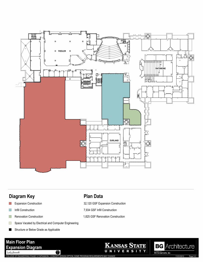
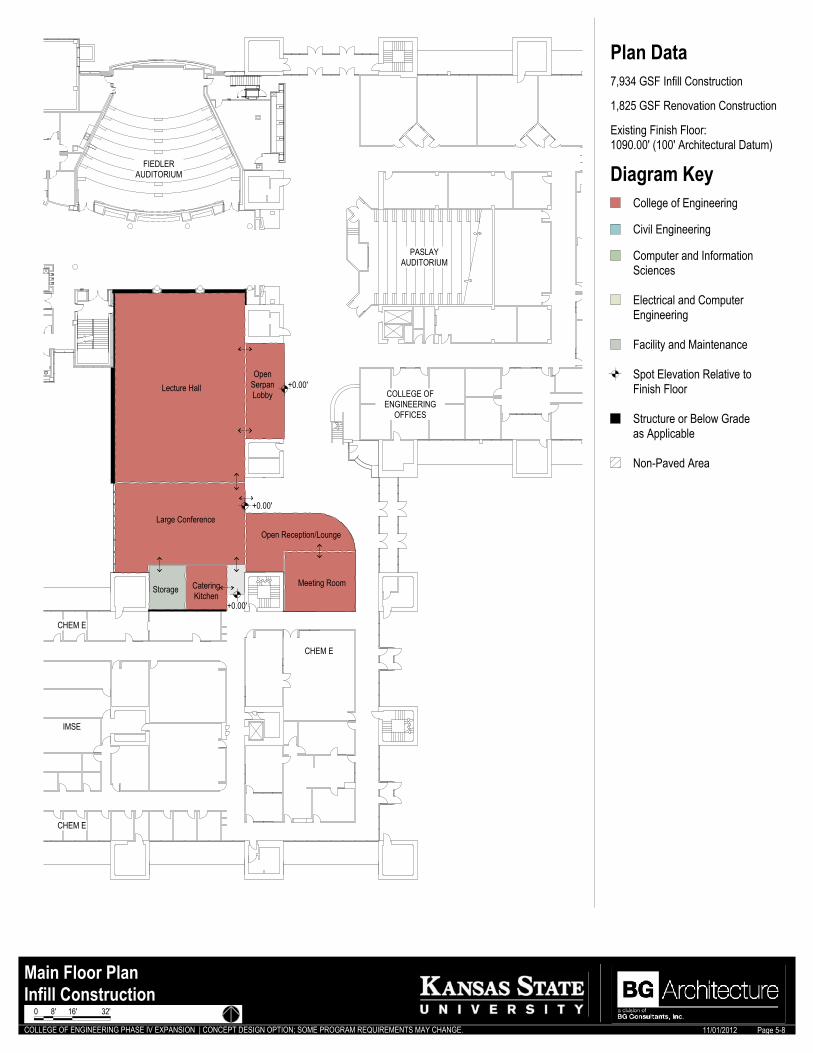
Expansion DiagramMain Floor Plan
32,120 GSF Expansion Construction
Plan Data
7,934 GSF Infill Construction
1,825 GSF Renovation Construction
Page 5-3

COLLEGE OF ENGINEERING PHASE IV EXPANSION | CONCEPT DESIGN OPTION; SOME PROGRAM REQUIREMENTS MAY CHANGE. 11/01/2012
FIEDLER
RATHBONE
DURLAND
SS
SS
SS
SS
SS
SS
0 8' 16' 32'
Diagram KeyExpansion Construction
Infill Construction
Renovation Construction
Space Vacated by Electrical and Computer Engineering
Structure or Below Grade as Applicable
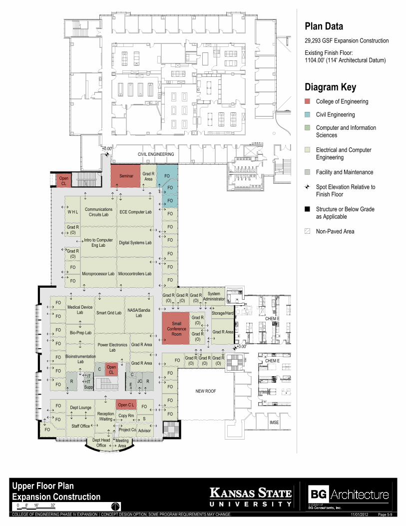
Expansion DiagramUpper Floor Plan
29,293 GSF Expansion Construction
Plan Data
20,623 GSF Vacated by Electrical and Computer Engineering (for reference only)
Page 5-4

COLLEGE OF ENGINEERING PHASE IV EXPANSION | CONCEPT DESIGN OPTION; SOME PROGRAM REQUIREMENTS MAY CHANGE. 11/01/2012
+0.00'
+0.00'
+0.00'
+0.00'
+0.00'
+0.00'
+0.00'
+0.00'
-4.00'
-3.00' - -6.00'
+0.00'
REACTION WALLREACTION WALL
DN
StructureAbove
DN
DN
DN
FIEDLER
DURLAND
Receiving Area
Structures Lab
WashPit
InstrRm
InsulPump
ControlRm
BioinformaticsLab
Robotics Lab
Competition Space
Competition Space
GK-12/EmbeddedSystem Lab
Mechanical
Central SupportSpace
Student Shop
Support Space
Ramp
LoadingDock
Program Adaptable
+8.00' - +10.00'
E
R
R
Electrical and ComputerEngineering
College of Engineering
Civil Engineering
Computer and InformationSciences
Spot Elevation Relative toFinish Floor
Diagram Key
Facility and Maintenance
Structure or Below Gradeas Applicable
Non-Paved Area
Expansion ConstructionLower Floor Plan
25,531 GSF Expansion Construction
Plan Data
Existing Finish Floor:1075.00' (85' Architectural Datum)
Page 5-5
0 8' 16' 32'

COLLEGE OF ENGINEERING PHASE IV EXPANSION | CONCEPT DESIGN OPTION; SOME PROGRAM REQUIREMENTS MAY CHANGE. 11/01/2012
+0.00
+0.00
StructureAbove
RATHBONE
DURLAND DURLAND
Mechanical
Electrical and ComputerEngineering
College of Engineering
Civil Engineering
Computer and InformationSciences
Spot Elevation Relative toFinish Floor
Diagram Key
Facility and Maintenance
Structure or Below Gradeas Applicable
Non-Paved Area
Infill ConstructionLower Floor Plan
2,495 GSF Infill Construction
Plan Data
Existing Finish Floor:1075.00' (85' Architectural Datum)
Page 5-6
0 8' 16' 32'
COLLEGE OF ENGINEERING PHASE IV EXPANSION | CONCEPT DESIGN OPTION; SOME PROGRAM REQUIREMENTS MAY CHANGE. 11/01/2012
-7.00'- -9.00'
+0.00'
+0.00'
+0.00'
FIEDLER LIBRARY
EXIST ROOF
CHEM E
IMSE
CHEM E
JC
Reception/Waiting
DeptHeadOffice
MeetingArea
FO
FO
FO
FO
FO
FO
FO
FO
FO
FO
Tech
Kedzie Multi_AgentRobotics Lab
CopyRm
S
FO
FO
FO
FO
FO
FO
FO
Data CenterTeaching Lab
S
SAOSAOFOFOFO
Storage/Hardware
ProgAdapt
C
Lac
(VE)Recording
Medium ConferenceFO
FO
FO
Teaching Lab
Large CollegeClassroom
CollegeClassroom
Seminar
SpecializedTeaching Lab
S
SecurityLab
KDDLab
C
FO
Cyber Defense
GeneralTeaching
Lab
OpenC L
CollegeClassroom
RR
SOSO
HighAssurance
SO FO
Dept Lounge
ITSupp
IT
E
R
R
Electrical and ComputerEngineering
College of Engineering
Civil Engineering
Computer and InformationSciences
Spot Elevation Relative toFinish Floor
Diagram Key
Facility and Maintenance
Structure or Below Gradeas Applicable
Non-Paved Area
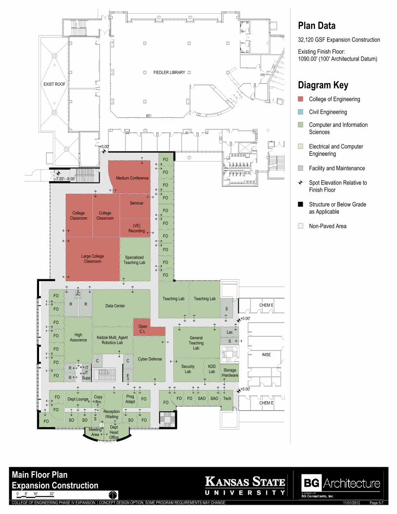
Expansion ConstructionMain Floor Plan
32,120 GSF Expansion Construction
Plan Data
Existing Finish Floor:1090.00' (100' Architectural Datum)
Page 5-7
0 8' 16' 32'
COLLEGE OF ENGINEERING PHASE IV EXPANSION | CONCEPT DESIGN OPTION; SOME PROGRAM REQUIREMENTS MAY CHANGE. 11/01/2012
+0.00'
+0.00'
+0.00'
CHEM E
IMSE
FIEDLERAUDITORIUM
PASLAYAUDITORIUM
COLLEGE OFENGINEERING
OFFICES
CHEM E
CHEM E
Large Conference
CateringKitchen
Storage
OpenSerpanLobby
Lecture Hall
Meeting Room
Open Reception/Lounge
Electrical and ComputerEngineering
College of Engineering
Civil Engineering
Computer and InformationSciences
Spot Elevation Relative toFinish Floor
Diagram Key
Facility and Maintenance
Structure or Below Gradeas Applicable
Non-Paved Area
Infill ConstructionMain Floor Plan
7,934 GSF Infill Construction
Plan Data
1,825 GSF Renovation Construction
Existing Finish Floor:1090.00' (100' Architectural Datum)
Page 5-8
0 8' 16' 32'
COLLEGE OF ENGINEERING PHASE IV EXPANSION | CONCEPT DESIGN OPTION; SOME PROGRAM REQUIREMENTS MAY CHANGE. 11/01/2012
+0.00'
+0.00'
CHEM E
IMSE
CIVIL ENGINEERING
NEW ROOF
MeetingArea
Open C L
Copy Rm
Grad R Area
SystemAdministrator
SmallConference
Room Grad R AreaBio-Prep Lab
Seminar
Advisor
Power ElectronicsLab
Grad R Area
FO
CJC
Dept Lounge
S
C OpenCL
SS
SSSS
SS
SS
CHEM E
Microprocessor Lab
Dept HeadOffice
FO
Intro to ComputerEng Lab
CommunicationsCircuits Lab
Microcontrollers Lab
Digital Systems Lab
ECE Computer Lab
Staff OfficeProject Co.
Storage/Hard
FO
Reception/Waiting
W H L
Grad R(O)
FO
FO
FO
Medical DeviceLab
BioinstrumentationLab
FO
FO
FO Grad R(O)
Grad R(O)
Grad R(O)
FO
FO
FO
FO
FO
Grad R(O)
FO
FO
FO
FOSmart Grid Lab NASA/Sandia
Lab
FO
Grad R(O)
Grad R(O)
Grad R(O)
FO
FO
FOFO
FO
ITSupp
ITR
OpenCL
ER
FO
FO
FO
Grad R(O)
Grad R(O)
Grad RArea
Electrical and ComputerEngineering
College of Engineering
Civil Engineering
Computer and InformationSciences
Spot Elevation Relative toFinish Floor
Diagram Key
Facility and Maintenance
Structure or Below Gradeas Applicable
Non-Paved Area
Expansion ConstructionUpper Floor Plan
29,293 GSF Expansion Construction
Plan Data
Existing Finish Floor:1104.00' (114' Architectural Datum)
Page 5-9
0 8' 16' 32'
COLLEGE OF ENGINEERING PHASE IV EXPANSION | CONCEPT DESIGN OPTION; SOME PROGRAM REQUIREMENTS MAY CHANGE. 11/01/2012
Exist Bldg Proposed Bldg
LOWER FLOORELEV = 85'-0"
MAIN FLOORELEV = 100'-0"
UPPER FLOORELEV = 114'-0"
MIN CLEARANCE 14'-0"
Exist BldgProposed Bldg
LOWER FLOORELEV = 85'-0"
MAIN FLOORELEV = 100'-0"
UPPER FLOORELEV = 114'-0"
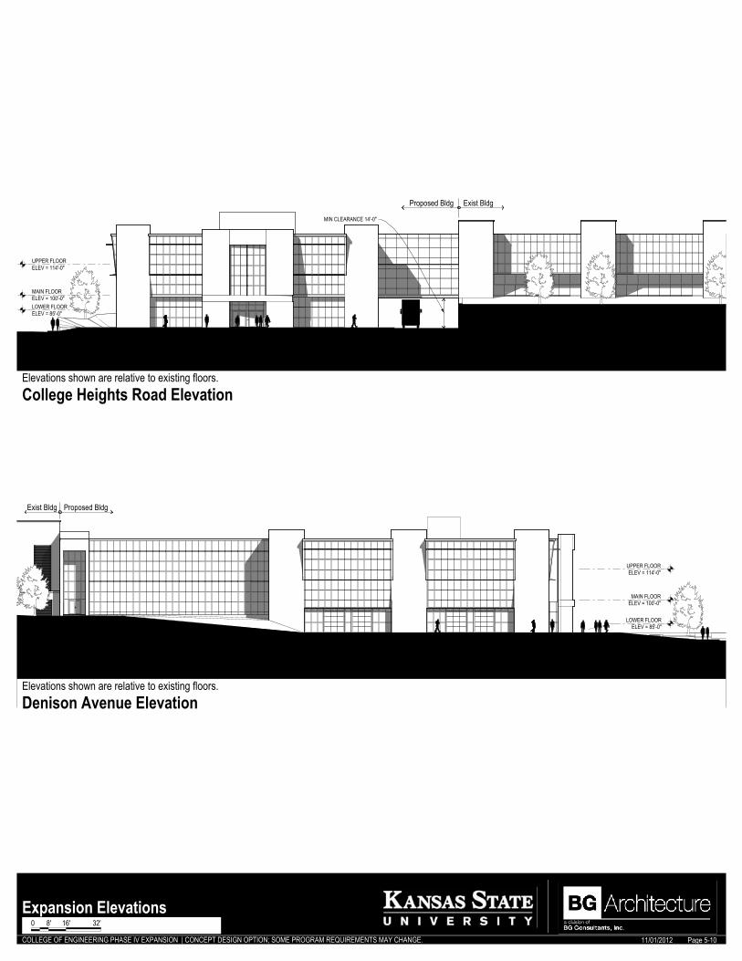
Expansion Elevations
Denison Avenue Elevation
College Heights Road ElevationElevations shown are relative to existing floors.
Elevations shown are relative to existing floors.
Page 5-10
0 8' 16' 32'
COLLEGE OF ENGINEERING PHASE IV EXPANSION | CONCEPT DESIGN OPTION; SOME PROGRAM REQUIREMENTS MAY CHANGE. 11/01/2012
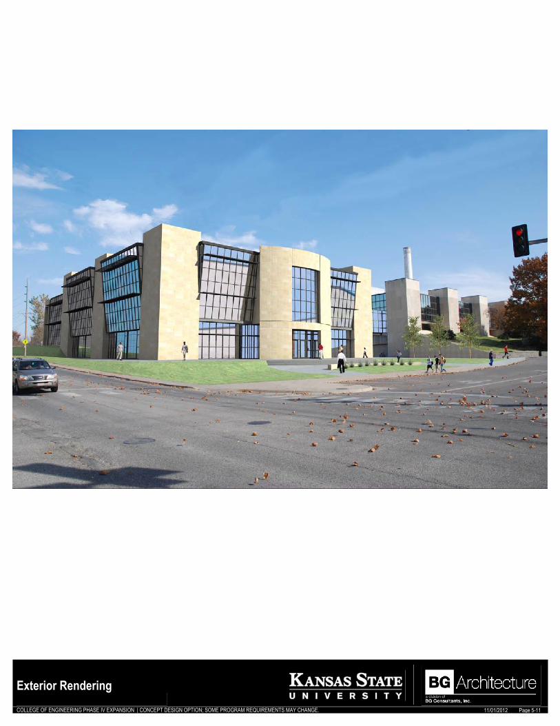
Exterior RenderingPage 5-11
0 8' 16' 32'

COLLEGE OF ENGINEERING PHASE IV EXPANSION | CONCEPT DESIGN OPTION; SOME PROGRAM REQUIREMENTS MAY CHANGE. 11/01/2012
Interior RenderingPage 5-12

Architectural Program | College of Engineering Phase IV Expansion
BG Architecture | November 1, 2012 Page 7-1
Appendix A College of Engineering Phase IV Expansion summary. Figure A-1. Phase IV Expansion summary, by space use category. Gross Sq. Ft. (GSF) 99,198 100% Net Usable Sq. Ft. (NUSF) 89,278 *90% *10% Net Assignable Sq. Ft. (NASF) 64.62% Total Non-Assignable 35.38% Space Use Category Usable space based upon its primary use (See Appendix D)
Non-Assignable (NSF) *25.38%
*10%
Inst
ruct
iona
l Spa
ce
18%
Res
earc
h S
pace
25
%
Lect
ure
Hal
l
7%
Hos
pita
lity
Cen
ter
2%
Offi
ce
14%
Dep
t. S
uite
5%
Con
fere
nce
Spac
e
6%
Com
petit
ion
11%
Loun
ge/S
emin
ar
4%
Oth
er
8%
Build
ing
Ser
vice
s
Spa
ce u
sed
to s
uppo
rt bu
ildin
g cl
eani
ng a
nd p
ublic
hyg
iene
fu
nctio
ns
Circ
ulat
ion
Spa
ces
requ
ired
for p
hysi
cal a
cces
s to
floo
rs o
r sub
divi
sion
s of
spa
ce w
ithin
the
build
ing,
whe
ther
par
titio
ned
or n
ot
Mec
hani
cal
Spa
ces
of a
bui
ldin
g de
sign
ed to
hou
se m
echa
nica
l eq
uipm
ent a
nd u
tility
ser
vice
s, a
nd s
haft
area
s
Stru
ctur
al
Incl
udes
wal
ls, f
loor
stru
ctur
e an
d ot
her b
uild
ing
com
pone
nts
Program Defined Spaces Types of spaces as organized in the numeric program (See Numeric Program)
G. A
cade
mic
Spa
ce
13%
G. A
cade
mic
Sup
port
11%
G. S
uppo
rt 13
%
Dep
artm
enta
l Sui
te
5%
Aca
dem
ic S
uppo
rt 12
%
Sys
tem
Adm
inis
tratio
n 2%
Inst
ruct
iona
l Spa
ces
12%
Res
earc
h S
pace
s 27
%
Flex
and
Fac
ility
Sup
. 5%
*Anticipated values reflect common percentages for the building type and construction developed during the programming phase. Figure A-2. Engineering Space Categories. Space Type Associated NASF Percent of Total NASF Space Committed to Engineering Classrooms 16,409 24% Space Committed to Engineering Labs 15,420 23% Figure A-3. Phase IV Expansion Levels of Construction. Represented Levels of Construction Associated Sq. Ft. Relative
Cost per Sq. Ft. Infill Construction 10,429 *$324 Expansion Construction 86,944 *$310 Renovation Construction 1825 *$225 *Relative Cost per Sq. Ft. values are based upon the anticipated Scope of Work associated with each level of Construction and as based upon the general concept developed during the programming phase.
A

Architectural Program | College of Engineering Phase IV Expansion
BG Architecture | November 1, 2012 Page 8-1
Appendix B The following section defines detailed space requirements for programmed areas as determined by evaluation of existing and proposed conditions for each space. This information is provided as a means to guide the success of the College of Engineering Phase IV Expansion. Listed requirements are minimums and establish a base standard for each space and some items suggest that code requirements may not be sufficient for the space. Further discussion with Department and Faculty is anticipated for clarification. General Building Requirements General Criteria: All spaces should be designed for adaptability to technology, comfort, safety and energy efficiency.
Accessibility: All floors and spaces shall accommodate wheelchair users according to ADA guidelines. Wall Construction, Interior: Interior walls will be designed to be scuff and impact resistant. Surfaces will be easily cleanable. Wall bumpers and or corner guards will be provided where appropriate to accommodate the anticipated traffic flow. Floors: Interior floors shall be smooth, non-slip. Floor finish will be appropriate to use and as approved by Kansas State University Standards. All teaching areas shall be flat-floored unless otherwise noted. Ceilings: Ceiling heights shall be established during design with a minimum 10’-0” height at instructional and research spaces. Doors and Hardware: Doors shall be 36” wide clear opening by 84” high. Minimum 60” wide clear opening (36” leaf and 24” leaf minimum) by 84” high at research labs. Other storage and support spaces are to have 42” or 48” doors. Doors and door hardware will be heavy-duty grade. Doors shall be full flush with vision panels where appropriate, with fire rated doors and glass where required. Wood doors or metal are equally suited for Engineering labs. All hardware shall be ADA compliant. Air Conditioning: All spaces are to be conditioned. Convenience Outlets: Due to the growing trend towards personal laptops and other handheld electronic devices, all spaces shall be evaluated for relative need for additional power outlets for user access. These are to be generously provided. Lighting: Lighting should be designed appropriate to space activities and needs. Daylighting: Where possible, natural daylight is to be integrated as an important element within the building design. Light wells, atriums, skylights, perimeter circulation paths with interior spaces receiving “borrowed” light are a few opportunities that may be explored. Mechanical Systems: Provide all spaces with appropriate air change and ventilation.
Finish Criteria: In general, all finishes shall be durable, smooth and cleanable to the greatest extent possible. Considerations should be made for activities and amount of use anticipated. All architectural finishes for service areas such as restrooms, mechanical, electrical, and storage rooms shall be durable and damage resistant as appropriate for their intended use.
B
Architectural Program | College of Engineering Phase IV Expansion
BG Architecture | November 1, 2012 Page 8-2
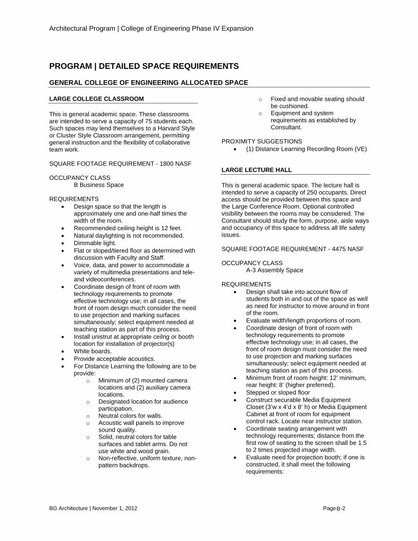
PROGRAM | DETAILED SPACE REQUIREMENTS GENERAL COLLEGE OF ENGINEERING ALLOCATED SPACE LARGE COLLEGE CLASSROOM This is general academic space. These classrooms are intended to serve a capacity of 75 students each. Such spaces may lend themselves to a Harvard Style or Cluster Style Classroom arrangement, permitting general instruction and the flexibility of collaborative team work. SQUARE FOOTAGE REQUIREMENT - 1800 NASF OCCUPANCY CLASS B Business Space REQUIREMENTS
• Design space so that the length is approximately one and one-half times the width of the room.
• Recommended ceiling height is 12 feet. • Natural daylighting is not recommended. • Dimmable light. • Flat or sloped/tiered floor as determined with
discussion with Faculty and Staff. • Voice, data, and power to accommodate a
variety of multimedia presentations and tele- and videoconferences.
• Coordinate design of front of room with technology requirements to promote effective technology use; in all cases, the front of room design much consider the need to use projection and marking surfaces simultaneously; select equipment needed at teaching station as part of this process.
• Install unistrut at appropriate ceilng or booth location for installation of projector(s)
• White boards. • Provide acceptable acoustics. • For Distance Learning the following are to be
provide: o Minimum of (2) mounted camera
locations and (2) auxiliary camera locations.
o Designated location for audience participation.
o Neutral colors for walls. o Acoustic wall panels to improve
sound quality. o Solid, neutral colors for table
surfaces and tablet arms. Do not use white and wood grain.
o Non-reflective, uniform texture, non-pattern backdrops.
o Fixed and movable seating should be cushioned.
o Equipment and system requirements as established by Consultant.
PROXIMITY SUGGESTIONS
• (1) Distance Learning Recording Room (VE) LARGE LECTURE HALL This is general academic space. The lecture hall is intended to serve a capacity of 250 occupants. Direct access should be provided between this space and the Large Conference Room. Optional controlled visibility between the rooms may be considered. The Consultant should study the form, purpose, aisle ways and occupancy of this space to address all life safety issues. SQUARE FOOTAGE REQUIREMENT - 4475 NASF OCCUPANCY CLASS A-3 Assembly Space REQUIREMENTS
• Design shall take into account flow of students both in and out of the space as well as need for instructor to move around in front of the room.
• Evaluate width/length proportions of room. • Coordinate design of front of room with
technology requirements to promote effective technology use; in all cases, the front of room design must consider the need to use projection and marking surfaces simultaneously; select equipment needed at teaching station as part of this process.
• Minimum front of room height: 12’ minimum, rear height: 8’ (higher preferred).
• Stepped or sloped floor • Construct securable Media Equipment
Closet (3’w x 4’d x 8’ h) or Media Equipment Cabinet at front of room for equipment control rack. Locate near instructor station.
• Coordinate seating arrangement with technology requirements; distance from the first row of seating to the screen shall be 1.5 to 2 times projected image width.
• Evaluate need for projection booth; if one is constructed, it shall meet the following requirements:
B

Architectural Program | College of Engineering Phase IV Expansion
BG Architecture | November 1, 2012 Page 8-3
o 42 sf minimum size o Angled projection window 4’ above
floor • Dimmable light. • Low voltage connection to teaching station. • Install unistrut at appropriate ceiling or booth
location for installation of projector(s) • Provided complete blackout capability. • Provide acceptable acoustics. • Anti-static finishes (floor and upholstery) • Natural daylighting is not desirable. • Choose all seating with consideration of
ergonomic principles. • White boards.
PROXIMITY SUGGESTIONS
• Large Conference Room • Existing lecture halls • Restrooms
DISTANCE LEARNING RECORDING ROOM (VE) This is general academic space. This support space serves to house the audio and visual control systems and technology to facilitate academic delivery for Distance Learning curriculum. Incorporates videoconferencing for teaching and learning. Room systems produce origination of audio and video for two-way communication. Control systems permit manipulation by instructor. Cameras capture live video of the teaching area and audience, with at least one area for audience feedback. It is desired that this space have direct visibility into at least (2) classrooms, although remote monitoring is acceptable. SQUARE FOOTAGE REQUIREMENT - 350 NASF OCCUPANCY CLASS B Business Space REQUIREMENTS
• Natural daylighting is not recommended. • Dimmable light. • Provide acceptable acoustics.
PROXIMITY SUGGESTIONS
• Large Departmental Classroom • Departmental Classroom • Small Conference Room
COLLEGE CLASSROOM This is general academic space. These classrooms are intended to serve a capacity of 30 students. Such
spaces may lend themselves to a traditional classroom arrangement, permitting general instruction and adaptation. SQUARE FOOTAGE REQUIREMENT - 945 NASF OCCUPANCY CLASS B Business Space REQUIREMENTS
• Length-to-width ratio should be 3:2. • Recommended ceiling height is 12 feet. • Natural daylighting is not recommended. • Dimmable light. • Provide acceptable acoustics. • Glare from windows controlled. • Voice, data, and power to accommodate a
variety of multimedia presentations and tele- and videoconferences.
• Provide acceptable acoustics. • Coordinate design of front of room with
technology requirements to promote effective technology use; in all cases, the front of room design much consider the need to use projection and marking surfaces simultaneously; select equipment needed at teaching station as part of this process.
• Install unistrut at appropriate ceilng or booth location for installation of projector(s)
• White boards. • For Distance Learning the following are to be
provide: o Minimum of (2) mounted camera
locations and (2) auxiliary camera locations.
o Designated location for audience participation.
o Neutral colors for walls. o Acoustic wall panels to improve sound
quality. o Solid, neutral colors for table surfaces
and tablet arms. Do not use white and wood grain.
o Non-reflective, uniform texture, non-pattern backdrops.
o Carpet floor throughout when possible. o Fixed and movable seating should be
cushioned. o Equipment and system requirements as
established by Consultant.
PROXIMITY SUGGESTIONS • Distance Learning Recording Room (VE)
B

Architectural Program | College of Engineering Phase IV Expansion
BG Architecture | November 1, 2012 Page 8-4
[HOSPITALITY CENTER] RECEPTION AREA / LOUNGE This is general academic support space. Hospitality space for prospective students, parents, faculty, and alumni should be located near the primary entry of the building. This space should be designed to represent the College of Engineering and serve as a welcome area designed for comfort and interaction. SQUARE FOOTAGE REQUIREMENT - 700 NASF OCCUPANCY CLASS B Business Space REQUIREMENTS
• Reception desk for (2) desk stations. • Casual seating/lounge area. • Soft flooring for comfort and acoustics. • Natural daylighting is recommended.
PROXIMITY SUGGESTIONS
• Entry [HOSPITALITY CENTER] MEETING ROOM This is general academic support space. Orientation room for prospective students and student organization meetings. SQUARE FOOTAGE REQUIREMENT - 750 NASF OCCUPANCY CLASS B Business Space REQUIREMENTS
• Design for flexibility. • Recommended ceiling height is 12’-0”. • Natural daylighting is optional. • Controlled views into space are
recommended. • Requires acoustic separation. • Black-out ability. • Voice, data, and power to accommodate a
variety of multimedia presentations and tele- and videoconferences.
• Dimmable lighting. • White boards and projection screens. • Acoustical separation from surrounding
spaces, is recommended. PROXIMITY SUGGESTIONS
• Entry • Reception Area/Lounge
LARGE CONFERENCE ROOM This is general academic support space. Large meeting room for up to 60 occupants. This space should include an area with small kitchenette for hospitality. Direct access should be provided from this room into the Large Lecture Hall, with optional controlled visibility. SQUARE FOOTAGE REQUIREMENT - 1850 NASF OCCUPANCY CLASS B Business Space REQUIREMENTS
• Design for flexibility. • Recommended ceiling height is 12’-0”. • Natural daylighting is optional. • Controlled views into space are
recommended. • Voice, data, and power to accommodate a
variety of multimedia presentations and tele- and videoconferences.
• Dimmable lighting. • Coordinate design of front of room with
technology requirements to promote effective technology use; in all cases, the front of room design much consider the need to use projection and marking surfaces simultaneously; select equipment needed at teaching station as part of this process.
• Install unistrut at appropriate ceilng or booth location for installation of projector(s)
• White boards and projection screens. • Acoustical separation from surrounding
spaces. • Provide counter and cabinet millwork to
support food serving and storage requirements.
PROXIMITY SUGGESTIONS
• Entry • Reception Area/Lounge • Catering Kitchen • Large Lecture Hall
MEDIUM CONFERENCE ROOM This is general academic support space. Mid-sized meeting room for up to 40 occupants. Used for formal meeting, training, and teleconference activities. This space may be designed for temporary partitioning into smaller spaces and should include an area with small kitchenette, counter and cabinet millwork to support food serving and storage requirements for hospitality.
B
Architectural Program | College of Engineering Phase IV Expansion
BG Architecture | November 1, 2012 Page 8-5
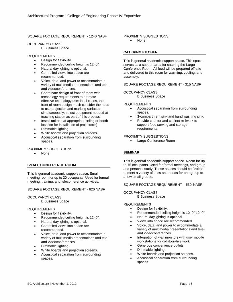
SQUARE FOOTAGE REQUIREMENT - 1240 NASF OCCUPANCY CLASS B Business Space REQUIREMENTS
• Design for flexibility. • Recommended ceiling height is 12’-0”. • Natural daylighting is optional. • Controlled views into space are
recommended. • Voice, data, and power to accommodate a
variety of multimedia presentations and tele- and videoconferences.
• Coordinate design of front of room with technology requirements to promote effective technology use; in all cases, the front of room design much consider the need to use projection and marking surfaces simultaneously; select equipment needed at teaching station as part of this process.
• Install unistrut at appropriate ceilng or booth location for installation of projector(s)
• Dimmable lighting. • White boards and projection screens. • Acoustical separation from surrounding
spaces. PROXIMITY SUGGESTIONS
• None SMALL CONFERENCE ROOM This is general academic support space. Small meeting room for up to 20 occupants. Used for formal meeting, training, and teleconference activities. SQUARE FOOTAGE REQUIREMENT - 620 NASF OCCUPANCY CLASS B Business Space REQUIREMENTS
• Design for flexibility. • Recommended ceiling height is 12’-0”. • Natural daylighting is optional. • Controlled views into space are
recommended. • Voice, data, and power to accommodate a
variety of multimedia presentations and tele- and videoconferences.
• Dimmable lighting. • White boards and projection screens. • Acoustical separation from surrounding
spaces.
PROXIMITY SUGGESTIONS • None
CATERING KITCHEN This is general academic support space. This space serves as a support area for catering the Large Conference Room. All food will be prepared off-site and delivered to this room for warming, cooling, and assembly. SQUARE FOOTAGE REQUIREMENT - 315 NASF OCCUPANCY CLASS B Business Space REQUIREMENTS
• Acoustical separation from surrounding spaces.
• 3-compartment sink and hand washing sink. • Provide counter and cabinet millwork to
support food serving and storage requirements.
PROXIMITY SUGGESTIONS
• Large Conference Room SEMINAR This is general academic support space. Room for up to 15 occupants. Used for formal meetings, and group and personal study. These spaces should be flexible to meet a variety of uses and needs for one group to a few small groups. SQUARE FOOTAGE REQUIREMENT – 530 NASF OCCUPANCY CLASS B Business Space REQUIREMENTS
• Design for flexibility. • Recommended ceiling height is 10’-0”-12’-0”. • Natural daylighting is optional. • Views into space are recommended. • Voice, data, and power to accommodate a
variety of multimedia presentations and tele- and videoconferences.
• Integration of wall monitors with user mobile workstations for collaborative work.
• Generous convenience outlets. • Dimmable lighting. • White boards and projection screens. • Acoustical separation from surrounding
spaces.
B

Architectural Program | College of Engineering Phase IV Expansion
BG Architecture | November 1, 2012 Page 8-6
PROXIMITY SUGGESTIONS
• Provide (1) per floor. COMMON LOUNGE (CL) This is general academic support space. Dedicated open lounges for up to 24 users. This area may be concentrated into one area or distributed among floors. These spaces should be flexible permitting small group sessions and individual study. Lounges and work areas should be readily visible and centrally located where possible. SQUARE FOOTAGE REQUIREMENT - 365 NASF OCCUPANCY CLASS B Business Space REQUIREMENTS
• Design for flexibility. • Recommended ceiling height is 10’-0”-12’-0”. • Natural daylighting is optional. • Integration of wall monitors with user mobile
workstations for collaborative work, is optional.
• Generous convenience outlets. PROXIMITY SUGGESTIONS
• Separation from faculty offices.
COMPETITION SPACES This is general support space. Dedicated area of up to 6000 total NASF for collaborative and independent competition project development. Organization of space should permit greatest amount of flexibility possible to adapt to size and need of each application. These areas are to be showcased and, as such, permit greatest amount of visibility possible. Ability to control visibility for creative rights is also required. SQUARE FOOTAGE REQUIREMENT – 6000 Total NASF [5 SPACES ANTICIPATED] OCCUPANCY CLASS B Business Space REQUIREMENTS
• Design for flexibility. • Natural daylighting is recommended. • Dust control. • Gas/Utility Services including vacuum,
pneumatic supply, natural gas, oxygen, carbon dioxide and distilled water.
• Reliable and easy access to power, voice data and HVAC.
• Exposed ceiling is recommended. • Eyewash and deluge stations.
PROXIMITY SUGGESTIONS
• Student Shop
STUDENT SHOP This is general support space. Area dedicated for product fabrication. Space will accommodate equipment area and materials storage area. SQUARE FOOTAGE REQUIREMENT - 750 NASF OCCUPANCY CLASS B Business Space REQUIREMENTS
• Design for flexibility. • Exposed ceiling is recommended • Natural daylighting is optional. • Air conditioning is optional. Heating is
required. PROXIMITY SUGGESTIONS
• Central Service Support • Loading Dock • Competition Spaces
CENTRAL SERVICE SUPPORT This is general support space. This area serves as the central support space of the College of Engineering. Utilized for storage, equipment, and equipment repair. May include selective storage of hazardous materials such as fuels. SQUARE FOOTAGE REQUIREMENT - 750 NASF OCCUPANCY CLASS B Business Space REQUIREMENTS
• Exposed ceiling is recommended • Air conditioned is optional. Heating is
required. PROXIMITY SUGGESTIONS
• Student Shop • Competition Spaces • Loading Dock • Elevator
B
Architectural Program | College of Engineering Phase IV Expansion
BG Architecture | November 1, 2012 Page 8-7
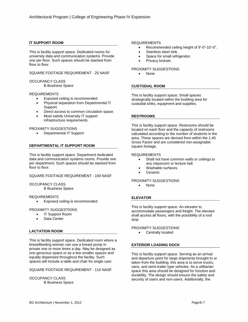
IT SUPPORT ROOM This is facility support space. Dedicated rooms for university data and communication systems. Provide one per floor. Such spaces should be stacked from floor to floor. SQUARE FOOTAGE REQUIREMENT - 25 NASF OCCUPANCY CLASS B Business Space REQUIREMENTS
• Exposed ceiling is recommended • Physical separation from Departmental IT
Support. • Direct access to common circulation space. • Must satisfy University IT support
infrastructure requirements. PROXIMITY SUGGESTIONS
• Departmental IT Support DEPARTMENTAL IT SUPPORT ROOM This is facility support space. Department dedicated data and communication systems rooms. Provide one per department. Such spaces should be stacked from floor to floor. SQUARE FOOTAGE REQUIREMENT - 100 NASF OCCUPANCY CLASS B Business Space REQUIREMENTS
• Exposed ceiling is recommended PROXIMITY SUGGESTIONS
• IT Support Room • Data Center
LACTATION ROOM This is facility support space. Dedicated room where a breastfeeding woman can use a breast pump in private one or more times a day. May be designed as one generous space or as a few smaller spaces and equally dispensed throughout the facility. Such spaces will include a table and chair for single user. SQUARE FOOTAGE REQUIREMENT - 110 NASF OCCUPANCY CLASS B Business Space
REQUIREMENTS
• Recommended ceiling height of 9’-0”-10’-0”. • Stainless steel sink. • Space for small refrigerator. • Privacy lockset.
PROXIMITY SUGGESTIONS
• None CUSTODIAL ROOM This is facility support space. Small spaces strategically located within the building area for custodial sinks, equipment and supplies. RESTROOMS This is facility support space. Restrooms should be located on each floor and the capacity of restrooms calculated according to the number of students in the area. These spaces are derived from within the 1.45 Gross Factor and are considered non-assignable square footage. REQUIREMENTS
• Shall not have common walls or ceilings to any classroom or lecture hall.
• Washable surfaces. • Ceramic
PROXIMITY SUGGESTIONS
• None ELEVATOR This is facility support space. An elevator to accommodate passengers and freight. The elevator shall access all floors, with the possibility of a roof stop. PROXIMITY SUGGESTIONS
• Centrally located EXTERIOR LOADING DOCK This is facility support space. Serving as an arrival and departure point for large shipments brought to or taken from the building, this area is to serve trucks, vans, and semi-trailer type vehicles. As a utilitarian space this area should be designed for function and durability. The design should ensure the safety and security of users and non-users. Additionally, the
B

Architectural Program | College of Engineering Phase IV Expansion
BG Architecture | November 1, 2012 Page 8-8
space should accommodate large vehicles, forklifts, and pedestrian traffic. REQUIREMENTS
• A ramp of maximum 1:12 slope shall be provided for vehicle access to the dock. A four foot high dock is anticipated.
• A dock leveler may be needed. • Adequate lighting. • The loading dock should be protected with
edge guards and dock bumpers. • Storm water management should be
addressed to prevent collection of storm water near or in the dock ramp area.
• Washable surfaces. • Provide railings to protect against fall and
vehicle separation at loading dock ramp areas.
• Consideration should be given for an outdoor radiant heat system.
PROXIMITY SUGGESTIONS
• None HALLWAYS AND CORRIDORS This is facility support space. Pedestrian circulation spaces provide opportunities for impromptu meetings and informal discussion. These spaces should be
regarded as opportune for social, academic, and research interactions. These spaces are derived from within the 1.45 Gross Factor and are considered non-assignable square footage. REQUIREMENTS
• Designed to provide opportunities for impromptu discussions and casual interactions.
• Sound-absorbent materials may be applied to the upper portion of walls for sound control.
• Lower portions of walls should be of durable and impact resistant finishes.
• Floors of hallways should be smooth to minimize noise and to aid the movement of equipment carts and wheelchairs.
• Floors should have a non-skid surface, especially near exterior entrances.
PROXIMITY SUGGESTIONS • None
CIVIL ENGINEERING ALLOCATED SPACE FACULTY OFFICE This is academic support space. Offices should be organized to facilitate a conversation zone at the door, a collaborative space for 2-3 people and a concentrated work area. SQUARE FOOTAGE REQUIREMENT - 140 NASF OCCUPANCY CLASS B Business Space REQUIREMENTS
• Natural daylighting is recommended. • White board. • Acoustical separation from surrounding
spaces. PROXIMITY SUGGESTIONS
• None.
STRUCTURES LAB This is a research space. Special conditions require volume to permit movement of ceiling crane for structural experiments and wall construction for structural tests. Additional spaces which support this lab are Insulated Pump Room, Control Room, and Instrumentation Room. SQUARE FOOTAGE REQUIREMENT - 4000 NASF OCCUPANCY CLASS B Business Space REQUIREMENTS
• 5-ton overhead crane covering strong floor and halfway over main level apron. (2 separate 5-ton bridges allow for installation of specimens in loading frames.)
• Strong Floor system with 100 kip rated anchor points integrated within 3’-0” thick concrete slab at 3’-0” o.c. each way.
B
Architectural Program | College of Engineering Phase IV Expansion
BG Architecture | November 1, 2012 Page 8-9
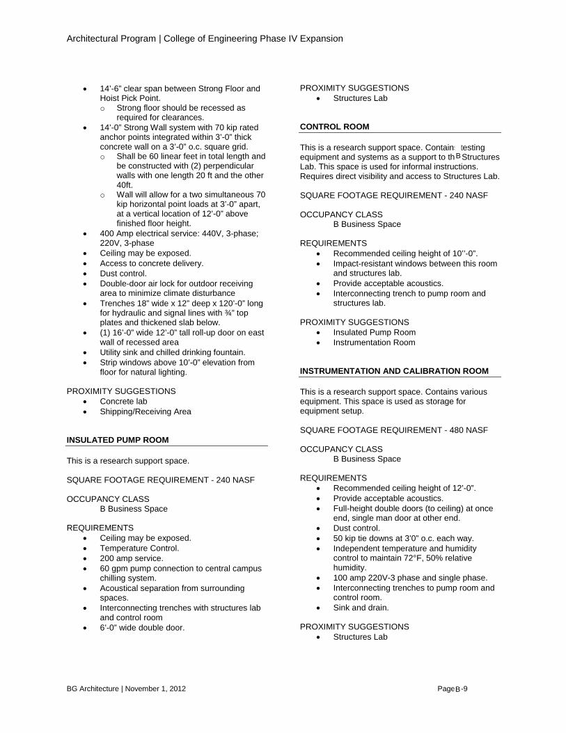
• 14’-6” clear span between Strong Floor and Hoist Pick Point. o Strong floor should be recessed as
required for clearances. • 14’-0” Strong Wall system with 70 kip rated
anchor points integrated within 3’-0” thick concrete wall on a 3’-0” o.c. square grid. o Shall be 60 linear feet in total length and
be constructed with (2) perpendicular walls with one length 20 ft and the other 40ft.
o Wall will allow for a two simultaneous 70 kip horizontal point loads at 3’-0” apart, at a vertical location of 12’-0” above finished floor height.
• 400 Amp electrical service: 440V, 3-phase; 220V, 3-phase
• Ceiling may be exposed. • Access to concrete delivery. • Dust control. • Double-door air lock for outdoor receiving
area to minimize climate disturbance • Trenches 18” wide x 12” deep x 120’-0” long
for hydraulic and signal lines with ¾” top plates and thickened slab below.
• (1) 16’-0” wide 12’-0” tall roll-up door on east wall of recessed area
• Utility sink and chilled drinking fountain. • Strip windows above 10’-0” elevation from
floor for natural lighting.
PROXIMITY SUGGESTIONS • Concrete lab • Shipping/Receiving Area
INSULATED PUMP ROOM This is a research support space. SQUARE FOOTAGE REQUIREMENT - 240 NASF OCCUPANCY CLASS B Business Space REQUIREMENTS
• Ceiling may be exposed. • Temperature Control. • 200 amp service. • 60 gpm pump connection to central campus
chilling system. • Acoustical separation from surrounding
spaces. • Interconnecting trenches with structures lab
and control room • 6’-0” wide double door.
PROXIMITY SUGGESTIONS • Structures Lab
CONTROL ROOM This is a research support space. Contains testing equipment and systems as a support to the Structures Lab. This space is used for informal instructions. Requires direct visibility and access to Structures Lab. SQUARE FOOTAGE REQUIREMENT - 240 NASF OCCUPANCY CLASS B Business Space REQUIREMENTS
• Recommended ceiling height of 10’’-0”. • Impact-resistant windows between this room
and structures lab. • Provide acceptable acoustics. • Interconnecting trench to pump room and
structures lab.
PROXIMITY SUGGESTIONS • Insulated Pump Room • Instrumentation Room
INSTRUMENTATION AND CALIBRATION ROOM This is a research support space. Contains various equipment. This space is used as storage for equipment setup. SQUARE FOOTAGE REQUIREMENT - 480 NASF OCCUPANCY CLASS B Business Space REQUIREMENTS
• Recommended ceiling height of 12’-0”. • Provide acceptable acoustics. • Full-height double doors (to ceiling) at once
end, single man door at other end. • Dust control. • 50 kip tie downs at 3’0” o.c. each way. • Independent temperature and humidity
control to maintain 72°F, 50% relative humidity.
• 100 amp 220V-3 phase and single phase. • Interconnecting trenches to pump room and
control room. • Sink and drain.
PROXIMITY SUGGESTIONS
• Structures Lab
B
B
Architectural Program | College of Engineering Phase IV Expansion
BG Architecture | November 1, 2012 Page 8-10
• Insulated Pump Room • Control Room
EXTERIOR WASH PIT This is area for cleaning equipment used for mixing heavy duty concrete and like materials. SQUARE FOOTAGE REQUIREMENT - 100 NSF REQUIREMENTS
• Reinforced concrete floors • Reinforced concrete walls
• Isolate from surrounding concrete slabs. • Accessible by bobcat type loaders. • Hot and cold water supply. • Removable metal grating on entire top
surface. • Top surface flush with surrounding area. • Stock/tank heaters to prevent freezing during
winter months. • Drainage.
PROXIMITY SUGGESTIONS
• Structures Lab
COMPUTER AND INFORMATION SCIENCES ALLOCATED SPACE RECEPTION OFFICE / WAITING This is departmental suite space. SQUARE FOOTAGE REQUIREMENT - 440 NASF OCCUPANCY CLASS B Business Space REQUIREMENTS
• Reception desk for (2) desk stations. • Casual seating/lounge area. • Soft flooring for comfort and acoustics. • Natural daylighting is recommended. • Power: 6 dual-gang duplex receptacle
distributed on walls (in proximity to desk stations), should be fed by conditioned power.
• Network: 8 Ethernet jacks for physical network connectivity, 2 in proximity to each desk stations, the other four distributed on walls in pairs.
PROXIMITY SUGGESTIONS
• Departmental Suite Entry
DEPARTMENT HEAD OFFICE This is departmental suite space. Offices should be organized to facilitate a collaborative/discussion space for 6-8 people and a concentrated work area. SQUARE FOOTAGE REQUIREMENT - 260 NASF OCCUPANCY CLASS B Business Space
REQUIREMENTS
• Soft flooring for comfort and acoustics. • Natural daylighting is recommended. • White board. • Acoustical separation from surrounding
spaces. • Power: 4 dual-gang duplex receptacles, 1 on
each wall, which should be fed by conditioned power.
• Network: 6 Ethernet jacks for physical network connectivity.
PROXIMITY SUGGESTIONS
• Within Departmental Suite. • Meeting Area
STAFF OFFICE This is departmental suite space. Such spaces should be organized for flexibility and productivity. The area is an open office. SQUARE FOOTAGE REQUIREMENT - 140 NASF OCCUPANCY CLASS B Business Space REQUIREMENTS
• Soft flooring for comfort and acoustics. • Natural daylighting is recommended. • White board. • Power: 4 dual-gang duplex receptacles, 1 on
each wall, which should be fed by conditioned power.
B
Architectural Program | College of Engineering Phase IV Expansion
BG Architecture | November 1, 2012 Page 8-11
• Network: 6 Ethernet jacks for physical network connectivity.
PROXIMITY SUGGESTIONS
• Within Departmental Suite. MEETING AREA This is departmental suite space. Small meeting room for up to 8 occupants. Used for formal meeting, training, and teleconference activities. This space may include an area with small kitchenette for hospitality. SQUARE FOOTAGE REQUIREMENT - 120 NASF OCCUPANCY CLASS B Business Space REQUIREMENTS
• Design for flexibility. • Recommended ceiling height is 10’-0”. • Natural daylighting is optional. • Controlled views into space are
recommended. • Voice, data, and power to accommodate a
variety of multimedia presentations and tele- and videoconferences.
• Dimmable lighting. • White boards and projection screens. • Acoustical separation from surrounding
spaces. • Power: 4 dual-gang duplex receptacles, 1 on
each wall, which should be fed by conditioned power.
• Network: 8 Ethernet jacks for physical network connectivity.
PROXIMITY SUGGESTIONS
• Within Departmental Suite. • Department Head Office
COPY AREA / BREAK ROOM This is departmental suite space. SQUARE FOOTAGE REQUIREMENT - 160 NASF PROXIMITY SUGGESTIONS
• Within Departmental Suite. • Staff Office • Reception Office / Waiting
REQUIREMENTS
• Power: 3 dual-gang duplex receptacles, which should be fed by conditioned power.
• Network: 6 Ethernet jacks for physical network connectivity.
PROXIMITY SUGGESTIONS • Within Departmental Suite.
STORAGE This is departmental suite space. Dedicated storage for department supplies and equipment. SQUARE FOOTAGE REQUIREMENT - 80 NASF PROXIMITY SUGGESTIONS
• Within Departmental Suite. • Copy Area / Break Room
DEPARTMENT LOUNGE This is academic support space. Intended for faculty and staff this area is not intended for students. A small kitchenette should be incorporated strategically into this space. SQUARE FOOTAGE REQUIREMENT - 400 NASF OCCUPANCY CLASS B Business Space REQUIREMENTS
• Casual seating/lounge area. • Natural daylighting is optional. • Acoustical separation from surrounding
spaces. • Odor separation from surrounding spaces.
PROXIMITY SUGGESTIONS
• Departmental Suite Entry • Staff/Faculty Offices
FACULTY OFFICE This is academic support space. Offices should be organized to facilitate a conversation zone at the door, a collaborative space for 2-3 people and a concentrated work area. SQUARE FOOTAGE REQUIREMENT - 140 NASF OCCUPANCY CLASS B Business Space REQUIREMENTS
B

Architectural Program | College of Engineering Phase IV Expansion
BG Architecture | November 1, 2012 Page 8-12
• Soft flooring for comfort and acoustics. • Natural daylighting is recommended. • White board. • Acoustical separation from surrounding
spaces. • Power: 4 dual-gang duplex receptacles, 1 on
each wall, which should be fed by conditioned power.
• Network: 8 Ethernet jacks for physical network connectivity.
PROXIMITY SUGGESTIONS
• None. SYSTEM ADMINISTRATOR OFFICE This is system administration space. SQUARE FOOTAGE REQUIREMENT - 140 NASF OCCUPANCY CLASS B Business Space REQUIREMENTS
• Soft flooring for comfort and acoustics. • Natural daylighting is recommended. • Acoustical separation from surrounding
spaces. • Power: 4 dual-gang duplex receptacles, 1 on
each wall, which should be fed by conditioned power.
• Network: 8 Ethernet jacks for physical network connectivity.
PROXIMITY SUGGESTIONS
• Data Center. • Technician Office. • Storage/Hardware.
TECHNICIAN OFFICE This is system administration space. SQUARE FOOTAGE REQUIREMENT - 140 NASF OCCUPANCY CLASS B Business Space REQUIREMENTS
• Soft flooring for comfort and acoustics. • Natural daylighting is recommended. • Acoustical separation from surrounding
spaces.
• Power: 4 dual-gang duplex receptacles, 1 on each wall, which should be fed by conditioned power.
• Network: 8 Ethernet jacks for physical network connectivity.
PROXIMITY SUGGESTIONS
• Data Center. • System Administrator Office. • Storage/Hardware.
STORAGE / HARDWARE This is system administration space. Desk and workbenches should be provided for IT hardware support personnel. Requires additional power and network connectivity in proximity to workbench space. SQUARE FOOTAGE REQUIREMENT - 250 NASF OCCUPANCY CLASS B Business Space REQUIREMENTS
• Acoustical separation from surrounding spaces.
• Natural daylighting is recommended. • Power: 8 dual-gang duplex receptacles,
which should be fed by conditioned power. • Network: 16 Ethernet jacks for physical
network connectivity. PROXIMITY SUGGESTIONS
• Data Center. • System Administrator Office. • Technician Office.
GENERAL TEACHING LAB This is instructional space. This classroom is intended to serve a capacity of 40 workstations. High usage space. Houses high end graphics/games programming workstations. Houses thin client desktops for high density with lower power and heat requirements. SQUARE FOOTAGE REQUIREMENT - 1200 NASF OCCUPANCY CLASS B Business Space REQUIREMENTS
• Length-to-width ratio should be 3:2. • Natural daylighting is not recommended. • Dimmable light.
B
B

Architectural Program | College of Engineering Phase IV Expansion
BG Architecture | November 1, 2012 Page 8-13
• Voice, data, and power to accommodate a variety of multimedia presentations.
• White boards and projection screens. • Acoustical separation from surrounding
spaces is recommended. • Security monitoring. • HVAC: independent from building
environment • Power: multiple circuits in proximity to
workstations, fed by conditioned power, dual-gang duplex receptacle at front for instructor, receptacles distributed in room for student use.
PROXIMITY SUGGESTIONS
• Specialized Classroom/Teaching Lab.
SPECIALIZED TEACHING LAB This is instructional space. Room arrangement places instructor at room end with evenly distributed circle tables in middle. Twenty high end graphics/games programming workstations are placed at the room perimeter. High usage space. SQUARE FOOTAGE REQUIREMENT - 1004 NASF OCCUPANCY CLASS B Business Space REQUIREMENTS
• Length-to-width ratio should be 3:2. • Natural daylighting is not recommended. • Dimmable light. • Flat floor, easily cleaned. • Voice, data, and power to accommodate a
variety of multimedia presentations. • White boards and projection screens. • Acoustical separation from surrounding
spaces is recommended. • Security monitoring. • HVAC: independent from building
environment. • Power: multiple circuits in proximity to
workstations, fed by conditioned power, dual-gang duplex receptacle at front for instructor, receptacles distributed in room for student use.
• Network: multiple Ethernet jacks in proximity to workstations, 2 Ethernet jacks at front of room for instructor.
PROXIMITY SUGGESTIONS
• General Teaching Lab.
TEACHING LABS This is instructional space. Spaces serve as computer labs dedicated to Windows or Linux. Arranged for instructor at one end with up to 24 workstations. SQUARE FOOTAGE REQUIREMENT - 800 NASF OCCUPANCY CLASS B Business Space REQUIREMENTS
• Length-to-width ratio should be 3:2. • Natural daylighting is not recommended. • Dimmable light. • Voice, data, and power to accommodate a
variety of multimedia presentations. • White boards and projection screens. • Acoustical separation from surrounding
spaces, is recommended. • Security monitoring. • HVAC: independent from building
environment. • Power: multiple circuits in proximity to
workstations, fed by conditioned power, dual-gang duplex receptacle at front for instructor, receptacles distributed in room for student use.
• Network: multiple Ethernet jacks in proximity to workstations, 2 Ethernet jacks at front of room for instructor.
PROXIMITY SUGGESTIONS
• None. ROBOTICS LAB This is research space. Space should be provided for workstations and collaborative work sessions with dedicated area for robot testing and manipulation. SQUARE FOOTAGE REQUIREMENT - 500 NASF OCCUPANCY CLASS B Business Space REQUIREMENTS
• Natural daylighting is optional. • White boards. • Acoustical separation from surrounding
spaces, is recommended. • Security monitoring. • HVAC: independent from building
environment. • Power: multiple circuits in proximity to
workstations, fed by conditioned power,
B

Architectural Program | College of Engineering Phase IV Expansion
BG Architecture | November 1, 2012 Page 8-14
dual-gang duplex receptacle at front for instructor, receptacles distributed in room for student use.
• Network: multiple Ethernet jacks in proximity to workstations.
PROXIMITY SUGGESTIONS
• None. SECURITY LAB This is research space. Space should be provided for workstations and collaborative work sessions and instruction. Area for (3) GRA workstations with furniture partitions is to be allocated. SQUARE FOOTAGE REQUIREMENT - 500 NASF OCCUPANCY CLASS B Business Space REQUIREMENTS
• White boards. • Acoustical separation from surrounding
spaces, is recommended. • Security monitoring. • HVAC: independent from building
environment. • Power: multiple circuits in proximity to
workstations, fed by conditioned power, receptacles distributed in room for student use.
• Network: multiple Ethernet jacks in proximity to workstations.
PROXIMITY SUGGESTIONS
• Cyber Defense Lab. KDD LAB This is research space. Space should be provided for workstations and collaborative work sessions with dedicated area for robot testing and manipulation. SQUARE FOOTAGE REQUIREMENT - 300 NASF OCCUPANCY CLASS B Business Space REQUIREMENTS
• White boards. • Acoustical separation from surrounding
spaces, is recommended. • Security monitoring.
PROXIMITY SUGGESTIONS
• None. HIGH ASSURANCE LAB This is research space, a combination of GRA spaces, meeting area and workstation tables. SQUARE FOOTAGE REQUIREMENT - 1000 NASF OCCUPANCY CLASS B Business Space REQUIREMENTS
• White boards. • Acoustical separation from surrounding
spaces, is recommended. • Security monitoring. • HVAC: independent from building
environment. • Power: multiple circuits in proximity to
workstations, fed by conditioned power, receptacles distributed in room for student use.
• Network: multiple Ethernet jacks in proximity to workstations.
• Hallway windows or windows storefront to showcase lab.
PROXIMITY SUGGESTIONS
• None. KEDZIE MULTI_AGENT ROBOTICS LAB This is research space. The space should be provided with 10 workstations and collaborative work sessions with a dedicated area for robot testing and manipulation. SQUARE FOOTAGE REQUIREMENT - 800 NASF OCCUPANCY CLASS B Business Space REQUIREMENTS
• White boards. • Acoustical separation from surrounding
spaces, is recommended. • Security monitoring. • HVAC: independent from building
environment. • Power: multiple circuits in proximity to
workstations, fed by conditioned power, receptacles distributed in room for student use.
B
Architectural Program | College of Engineering Phase IV Expansion
BG Architecture | November 1, 2012 Page 8-15
• Network: multiple Ethernet jacks in proximity to workstations.
• Hallway windows or windows storefront to showcase lab.
PROXIMITY SUGGESTIONS
• Cyber Defense Lab. GK-12 / EMBEDDED SYSTEMS LAB This is research space, a combination of GRA spaces, meeting area and workstation tables. SQUARE FOOTAGE REQUIREMENT - 600 NASF OCCUPANCY CLASS B Business Space REQUIREMENTS
• White boards. • Acoustical separation from surrounding
spaces, is recommended. • Security monitoring. • HVAC: independent from building
environment. • Power: multiple circuits in proximity to
workstations, fed by conditioned power, receptacles distributed in room for student use.
• Network: multiple Ethernet jacks in proximity to workstations.
• Hallway windows or windows storefront to showcase lab.
PROXIMITY SUGGESTIONS
• None. BIOINFORMATICS LAB This is research space. SQUARE FOOTAGE REQUIREMENT - 400 NASF OCCUPANCY CLASS B Business Space REQUIREMENTS
• White boards. • Acoustical separation from surrounding
spaces, is recommended. • Security monitoring.
PROXIMITY SUGGESTIONS
• None.
CYBER DEFENSE LAB This is research space. Houses 25-30 workstations for desktop security research which can be stacked densely to conserve space. Space should be provided for up to 2 GRA workstations with furniture partitions to be allocated. SQUARE FOOTAGE REQUIREMENT - 1200 NASF OCCUPANCY CLASS B Business Space REQUIREMENTS
• White boards. • Acoustical separation from surrounding
spaces, is recommended. • Security monitoring. • HVAC: independent from building
environment. • Power: multiple circuits in proximity to
workstations, fed by conditioned power, circuits in proximity to GRA workstations.
• Network: multiple Ethernet jacks in proximity to GRA workstations.
• Hallway windows or windows storefront to showcase lab.
PROXIMITY SUGGESTIONS
• Data Center • Kedzie Multi_Agent Lab. • Security Lab
DATA CENTER This is flex and facility support space. A facility for vertical stacked data processing equipment, including dense frame and rack-mounted processing systems. Showcase space. SQUARE FOOTAGE REQUIREMENT - 1500 NASF OCCUPANCY CLASS B Business Space REQUIREMENTS
• Raised access floor. • Durable anti-static surfaces. • Technological connectivity.
o Fiber-optic o 10GB connectivity to campus network
• Dual path service lines for power. Up to 600 kVA combined available.
• Uninterruptible power supply (UPS). 30 minute battery runtime.
B

Architectural Program | College of Engineering Phase IV Expansion
BG Architecture | November 1, 2012 Page 8-16
• HVAC with redundant components. Up to 170 tons (600kW) cooling capacity independent from building environment.
• Acoustical separation from surrounding spaces, is recommended.
• Security monitoring. • Backup generator to provide up to 600 kVA
of power in case of extended power outages or emergency.
• Electronic access door locks, keypad/swipe/RFDI.
• Hallway windows or windows storefront to showcase lab.
PROXIMITY SUGGESTIONS
• Vertical service core. • CIS System Administrator • CIS Technician • ECE System Administrator
PROGRAM ADAPTABLE This is flex and facility support space. To meet the future needs of the department, un-assigned space has been allocated. This area may be one large area or divisible into several. SQUARE FOOTAGE REQUIREMENT - 1500 NASF OCCUPANCY CLASS B Business Space REQUIREMENTS
• To be determined.
PROXIMITY SUGGESTIONS • None.
ELECTRICAL AND COMPUTER ENGINEERING ALLOCATED SPACE RECEPTION OFFICE / WAITING This is departmental suite space. SQUARE FOOTAGE REQUIREMENT - 440 NASF OCCUPANCY CLASS B Business Space REQUIREMENTS
• Reception desk for (2) desk stations. • Casual seating/lounge area. • Soft flooring for comfort and acoustics. • Natural daylighting is recommended.
PROXIMITY SUGGESTIONS
• Departmental Suite Entry
DEPARTMENT HEAD OFFICE This is departmental suite space. Offices should be organized to facilitate a collaborative/discussion space for 6-8 people and a concentrated work area. SQUARE FOOTAGE REQUIREMENT - 260 NASF OCCUPANCY CLASS B Business Space REQUIREMENTS
• Soft flooring for comfort and acoustics.
• Natural daylighting is recommended. • White board. • Acoustical separation from surrounding
spaces. PROXIMITY SUGGESTIONS
• Within Departmental Suite. • Project Coordinator. • Meeting Area
PROJECT COORDINATOR OFFICE This is departmental suite space. The office should be organized to facilitate a conversation zone at the door, a discussion space for 2-4 people and a concentrated work area. SQUARE FOOTAGE REQUIREMENT - 160 NASF OCCUPANCY CLASS B Business Space REQUIREMENTS
• Soft flooring for comfort and acoustics. • Natural daylighting is recommended. • White board. • Acoustical separation from surrounding
spaces. PROXIMITY SUGGESTIONS
• Within Departmental Suite.
B
B

Architectural Program | College of Engineering Phase IV Expansion
BG Architecture | November 1, 2012 Page 8-17
• Department Head Office. STAFF OFFICE This is departmental suite space. Such spaces should be organized for flexibility and productivity. The area may be a part of an open office. SQUARE FOOTAGE REQUIREMENT - 140 NASF OCCUPANCY CLASS B Business Space REQUIREMENTS
• Soft flooring for comfort and acoustics. • Natural daylighting is recommended. • White board.
PROXIMITY SUGGESTIONS
• Within Departmental Suite. ADVISORS OFFICE This is departmental suite space. The office should be organized to facilitate a conversation zone at the door, a discussion space for 2-4 people and a concentrated work area. This space is not required to be part of the Departmental Suite. SQUARE FOOTAGE REQUIREMENT - 160 NASF OCCUPANCY CLASS B Business Space REQUIREMENTS
• Soft flooring for comfort and acoustics. • Natural daylighting is recommended. • White board. • Acoustical separation from surrounding
spaces. PROXIMITY SUGGESTIONS
• None. COPY AREA / BREAK ROOM This is departmental suite space. This is a work area for faculty and staff. Adequate room for paper handling accessories including workspace, paper cutters, fax machine, and printers is required. Space should be adequate to facilitate 3 faculty members utilizing the space at once. SQUARE FOOTAGE REQUIREMENT - 180 NASF
PROXIMITY SUGGESTIONS
• Within Departmental Suite. • Staff Office • Reception Office / Waiting
STORAGE This is departmental suite space. Dedicated storage for department supplies and equipment. SQUARE FOOTAGE REQUIREMENT - 80 NASF PROXIMITY SUGGESTIONS
• Within Departmental Suite. • Copy Area / Break Room
MEETING AREA This is departmental suite space. Small meeting room for up to 8 occupants. Used for formal meeting, training, and teleconference activities. This space may include an area with small kitchenette for hospitality. SQUARE FOOTAGE REQUIREMENT - 120 NASF OCCUPANCY CLASS B Business Space REQUIREMENTS
• Design for flexibility. • Recommended ceiling height is 10’-0”. • Natural daylighting is optional. • Controlled views into space are
recommended. • Voice, data, and power to accommodate a
variety of multimedia presentations and tele- and videoconferences.
• Generous convenience outlets. • Dimmable lighting. • White boards and projection screens. • Acoustical separation from surrounding
spaces. PROXIMITY SUGGESTIONS
• Within Departmental Suite. • Department Head Office.
DEPARTMENT LOUNGE This is academic support space. Intended for faculty and staff this area is not intended for students. A
B

Architectural Program | College of Engineering Phase IV Expansion
BG Architecture | November 1, 2012 Page 8-18
small kitchenette should be incorporated strategically into this space. SQUARE FOOTAGE REQUIREMENT - 400 NASF OCCUPANCY CLASS B Business Space REQUIREMENTS
• Casual seating/lounge area. • Natural daylighting is optional. • Acoustical separation from surrounding
spaces. • Odor separation from surrounding spaces.
PROXIMITY SUGGESTIONS
• Departmental Suite Entry • Staff/Faculty Offices
FACULTY OFFICE This is academic support space. Offices should be organized to facilitate a conversation zone at the door, a collaborative space for 2-3 people and a concentrated work area. SQUARE FOOTAGE REQUIREMENT - 140 NASF OCCUPANCY CLASS B Business Space REQUIREMENTS
• Soft flooring for comfort and acoustics. • Natural daylighting is recommended. • White board. • Acoustical separation from surrounding
spaces. • Operable windows when available. • Ability to place two 5-foot work stations along
the same wall. PROXIMITY SUGGESTIONS
• Graduate research offices. SYSTEM ADMINISTRATOR / STUDENT ADMINISTRATOR This is system administration space. The space should be organized to provide space for 2-3 people and associated workstations, and an additional small area where computers being services can be held. SQUARE FOOTAGE REQUIREMENT - 250 NASF
OCCUPANCY CLASS B Business Space REQUIREMENTS
• Soft flooring for comfort and acoustics. • Natural daylighting is recommended. • Acoustical separation from surrounding
spaces. PROXIMITY SUGGESTIONS
• Data Center. • Storage/Hardware.
STORAGE / HARDWARE This is system administration space for temporary storage of computers and related equipment. SQUARE FOOTAGE REQUIREMENT - 200 NASF OCCUPANCY CLASS B Business Space REQUIREMENTS
• Acoustical separation from surrounding spaces.
PROXIMITY SUGGESTIONS
• System Administrator Office. COMPUTER LAB This is instructional space. This classroom is intended to serve a capacity of 20 workstations. High usage space. Supports ECE undergraduate and graduate students. Serves as a computer lab. SQUARE FOOTAGE REQUIREMENT - 740 NASF OCCUPANCY CLASS B Business Space REQUIREMENTS
• Length-to-width ratio should be 3:2. • Data and power to accommodate a variety of
multimedia presentations, including power and networking access from floor or ceiling.
• White boards and projection screens. • Acoustical separation from surrounding
spaces, is recommended. • Security monitoring. • Windows to provide visibility into the room.
PROXIMITY SUGGESTIONS
• None.
B

Architectural Program | College of Engineering Phase IV Expansion
BG Architecture | November 1, 2012 Page 8-19
DIGITAL SYSTEMS LAB This is instructional space. The space is used as a digital hardware and DSP lab. Room supports (4) courses. Moderately heavy scheduled usage, with 14 students per laboratory section. This lab utilizes equipment benches that are 8’x4’, each accommodating 2 students. SQUARE FOOTAGE REQUIREMENT - 740 NASF OCCUPANCY CLASS B Business Space REQUIREMENTS
• Length-to-width ratio should be 3:2. • Data and power to accommodate a variety of
multimedia presentations. • White boards and projection screens. • Acoustical separation from surrounding
spaces, is recommended. • Hallway widows which begin at 5’ above
floor are recommended.
PROXIMITY SUGGESTIONS • Microcontrollers Lab. • Microprocessor Lab. • Intro to Computer Engineering Lab.
MICROCONTROLLERS LAB This is instructional space. Services approximately 70 students per semester, with 14 students per laboratory section. This lab utilizes equipment benches that are 8’x4’, each accommodating 2 students. SQUARE FOOTAGE REQUIREMENT - 740 NASF OCCUPANCY CLASS B Business Space REQUIREMENTS
• Length-to-width ratio should be 3:2. • Data and power to accommodate a variety of
multimedia presentations. • White boards and projection screens. • Acoustical separation from surrounding
spaces, is recommended. • Hallway widows which begin at 5’ above
floor are recommended.
PROXIMITY SUGGESTIONS • Digital Systems Lab. • Microprocessor Lab. • Intro to Computer Engineering Lab.
MICROPROCESSOR LAB This is instructional space. Used for processor and real time classes and is a senior level embedded systems lab. Minimum student capacity is 20 occupants, but with 16 students per laboratory section. This lab utilizes equipment benches that are 8’x4’, each accommodating 2 students. Light scheduled usage. SQUARE FOOTAGE REQUIREMENT - 740 NASF OCCUPANCY CLASS B Business Space REQUIREMENTS
• Length-to-width ratio should be 3:2. • Data and power to accommodate a variety of
multimedia presentations. • White boards and projection screens. • Acoustical separation from surrounding
spaces, is recommended. • Hallway windows which begin at 5’ above
floor are recommended.
PROXIMITY SUGGESTIONS • Digital Systems Lab. • Intro to Computer Engineering Lab. • Microcontrollers Lab. • Hallway widows which begin at 5’ above
floor are recommended. INTRO TO COMPUTER ENGINEERING LAB This is instructional space. Services approximately 140 students per semester, with 14 students per laboratory section. This lab utilizes tables each accommodating 2 students. One table is required for the instructor use. Heavy scheduled usage. SQUARE FOOTAGE REQUIREMENT - 740 NASF OCCUPANCY CLASS B Business Space REQUIREMENTS
• Length-to-width ratio should be 3:2. • Data and power to accommodate a variety of
multimedia presentations. • White boards and projection screens. • Acoustical separation from surrounding
spaces, is recommended. • Security monitoring. • Hallway widows which begin at 4’-5’ above
floor are recommended.
B
Architectural Program | College of Engineering Phase IV Expansion
BG Architecture | November 1, 2012 Page 8-20
PROXIMITY SUGGESTIONS • Digital Systems Lab. • Microcontrollers Lab. • Microprocessor Lab.
COMMUNICATION CIRCUITS LAB This is instructional space. Traditional instructional layout with perimeter work benches, with the ability of 16 to work at benches. This lab utilizes equipment benches that are 8’x4’, each accommodating 2 students. SQUARE FOOTAGE REQUIREMENT - 740 NASF OCCUPANCY CLASS B Business Space REQUIREMENTS
• Length-to-width ratio should be 3:2. • Data and power to accommodate a variety of
multimedia presentations. • White boards and projection screens. • Acoustical separation from surrounding
spaces, is recommended. • Hallway widows which begin at 5’ above
floor are recommended.
PROXIMITY SUGGESTIONS • Communications Research.
GRADUATE RESEARCH OFFICE This is academic support space. GRA Offices should be organized to provide a collaborative space for 2-3 people and associated workstations. SQUARE FOOTAGE REQUIREMENT - 140 NASF OCCUPANCY CLASS B Business Space REQUIREMENTS
• Soft flooring for comfort and acoustics. • Natural daylighting is recommended. • White board. • Acoustical separation from surrounding
spaces. PROXIMITY SUGGESTIONS
• Research spaces.
GRADUATE RESEARCH AREA This is academic support space. GRA Offices should be organized to provide a collaborative space for 4-5 people and associated workstations. SQUARE FOOTAGE REQUIREMENT - 300 NASF OCCUPANCY CLASS B Business Space REQUIREMENTS
• Soft flooring for comfort and acoustics. • Natural daylighting is recommended. • White board. • Acoustical separation from surrounding
spaces. PROXIMITY SUGGESTIONS
• Research spaces. WIRELESS HARDWARE LAB This is research space consisting of 2-3 equipment benches and 2-3 desks. SQUARE FOOTAGE REQUIREMENT - 300 NASF OCCUPANCY CLASS B Business Space REQUIREMENTS
• Length-to-width ratio should be 3:2. • Data and power to accommodate a variety of
multimedia presentations. • White boards and projection screens. • Acoustical separation from surrounding
spaces, is recommended.
PROXIMITY SUGGESTIONS • NASA / Sandia • WiComm Group
POWER ELECTRONICS LAB This is research space. That will consist of both general work area and 6 benches that are 8’x4’, each accommodating 2 students, as well as a collaborative area for a meeting table and individual workstation area. SQUARE FOOTAGE REQUIREMENT - 740 NASF OCCUPANCY CLASS B Business Space
B

Architectural Program | College of Engineering Phase IV Expansion
BG Architecture | November 1, 2012 Page 8-21
REQUIREMENTS • Length-to-width ratio should be 3:2. • Data and power to accommodate a variety of
multimedia presentations. • White boards and projection screens. • Acoustical separation from surrounding
spaces, is recommended. • Electrical power availability in 120V, 240V
and 3-phase distributed around the room perimeter.
• Hallway widows which begin at 4’-5’ above floor are recommended.
PROXIMITY SUGGESTIONS
• Smart Grid Lab. NASA / SANDIA LAB This is research space. Perimeter benches with desks at center for GRAs performing computational work. SQUARE FOOTAGE REQUIREMENT - 700 NASF OCCUPANCY CLASS B Business Space REQUIREMENTS
• Length-to-width ratio should be 3:2. • Data and power to accommodate a variety of
multimedia presentations. • White boards and projection screens. • Acoustical separation from surrounding
spaces, is recommended. • Hallway widows which begin at 5’ above
floor are recommended.
PROXIMITY SUGGESTIONS • Wireless Hardware Lab.
[BIOMED RESEARCH LABS] BIOINSTRUMENTATION LAB This is research space which will house equipment benches, a small meeting area, and a desk area for graduate students. Showcase space. SQUARE FOOTAGE REQUIREMENT - 740 NASF OCCUPANCY CLASS B Business Space REQUIREMENTS
• Length-to-width ratio should be 3:2. • Data and power to accommodate a variety of
multimedia presentations.
• White boards and projection screens. • Acoustical separation from surrounding
spaces, is recommended. • Hallway widows which begin at 5’ above
floor are recommended. • Significant amount of cabinet storage
PROXIMITY SUGGESTIONS
• Bio-Prep Lab. [BIOMED RESEARCH LABS] MEDICAL DEVICES LAB This is research space which will house equipment benches, a small meeting area, and a desk area for graduate students. Showcase space. SQUARE FOOTAGE REQUIREMENT - 740 NASF OCCUPANCY CLASS B Business Space REQUIREMENTS
• Length-to-width ratio should be 3:2. • Data and power to accommodate a variety of
multimedia presentations. • White boards and projection screens. • Acoustical separation from surrounding
spaces, is recommended. • Hallway widows which begin at 5’ above
floor are recommended. • Significant amount of cabinet storage.
PROXIMITY SUGGESTIONS
• Bio-Prep Lab. [BIOMED RESEARCH LABS] BIO-PREP LAB This is research space. Intended to serve as the common wet lab between Bioinstrumentation and Medical Devices Labs, this space will house fume hoods, sinks, casework and associated medical fridges and freezers and supplemental equipment. SQUARE FOOTAGE REQUIREMENT – included in total as a part of both Bioinstrumentation and Medical Devices Labs. OCCUPANCY CLASS B Business Space REQUIREMENTS
• Constant and reliable HVAC • Dust control • Gas/Utility services
B
Architectural Program | College of Engineering Phase IV Expansion
BG Architecture | November 1, 2012 Page 8-22
o Vacuum o Pneumatic supply o Natural gas o Oxygen o Carbon Dioxide o Distilled water
• Fume hood • White boards. • Acoustical separation from surrounding
spaces, is recommended.
PROXIMITY SUGGESTIONS • Bioinstrumentation Lab • Medical Devices Lab
WIRELESS HARDWARE LAB This is research space consisting of 2-3 equipment benches and 2-3 desks. SQUARE FOOTAGE REQUIREMENT - 300 NASF OCCUPANCY CLASS B Business Space REQUIREMENTS
• Length-to-width ratio should be 3:2. • Data and power to accommodate a variety of
multimedia presentations. • White boards and projection screens. • Acoustical separation from surrounding
spaces, is recommended.
PROXIMITY SUGGESTIONS • NASA / Sandia
SMART GRID LAB This is research space consisting of: an equipment area for 6 standard 19” racks; a workstation area which houses 6-8 computers for conducting tests; an open area where visiting groups can watch demonstrations of the lab capabilities. This is a showcase lab. SQUARE FOOTAGE REQUIREMENT - 740 NASF OCCUPANCY CLASS B Business Space REQUIREMENTS
• Length-to-width ratio should be 3:2. • Data and power to accommodate a variety of
multimedia presentations. • White boards and projection screens.
• Acoustical separation from surrounding spaces, is recommended.
PROXIMITY SUGGESTIONS
• Data Center PROGRAM ADAPTABLE This is flex and facility support space. To meet the future needs of the department, un-assigned space has been allocated. This area may be one area or divisible into few. SQUARE FOOTAGE REQUIREMENT - 260 NASF OCCUPANCY CLASS B Business Space REQUIREMENTS
• To be determined.
PROXIMITY SUGGESTIONS • None.
ROOF LAB AREA This is a flex and facility support space. SQUARE FOOTAGE REQUIREMENT – 1500 - 2000 NSF OCCUPANCY CLASS B Business Space REQUIREMENTS
• 500 SF dedicated to equipment. • 1000 SF dedicated to collaborative work
activities, including a surface where human exercise experiments can be conducted.
• Data and power to accommodate equipment necessary to conduct experiments.
• Perimeter railing for safety. • Elevator access for transporting equipment.
PROXIMITY SUGGESTIONS
• None
B

Architectural Program | College of Engineering Phase IV Expansion
BG Architecture | November 1, 2012 Page 8-1
Appendix C The following section provides bubble relationship diagrams for various departments, spaces, areas, and uses as examined through analysis of existing facilities and trends in collegiate spaces. This is not exhaustive of all spaces or possibilities and was used during programming to prioritize needs. These diagrams are provided as a visual tool for guiding the designer in understanding the global organizing principles as well as needs, within individual spaces, that drove the program.
SPACE BUBBLE DIAGRAMS
1. College of Engineering Phase IV Expansion Diagram
C

Architectural Program | College of Engineering Phase IV Expansion
BG Architecture | November 1, 2012 Page 8-2
2. Typical ECE Teaching Lab Organization Diagram
3. Typical Faculty / Staff Office Organization Diagram
C
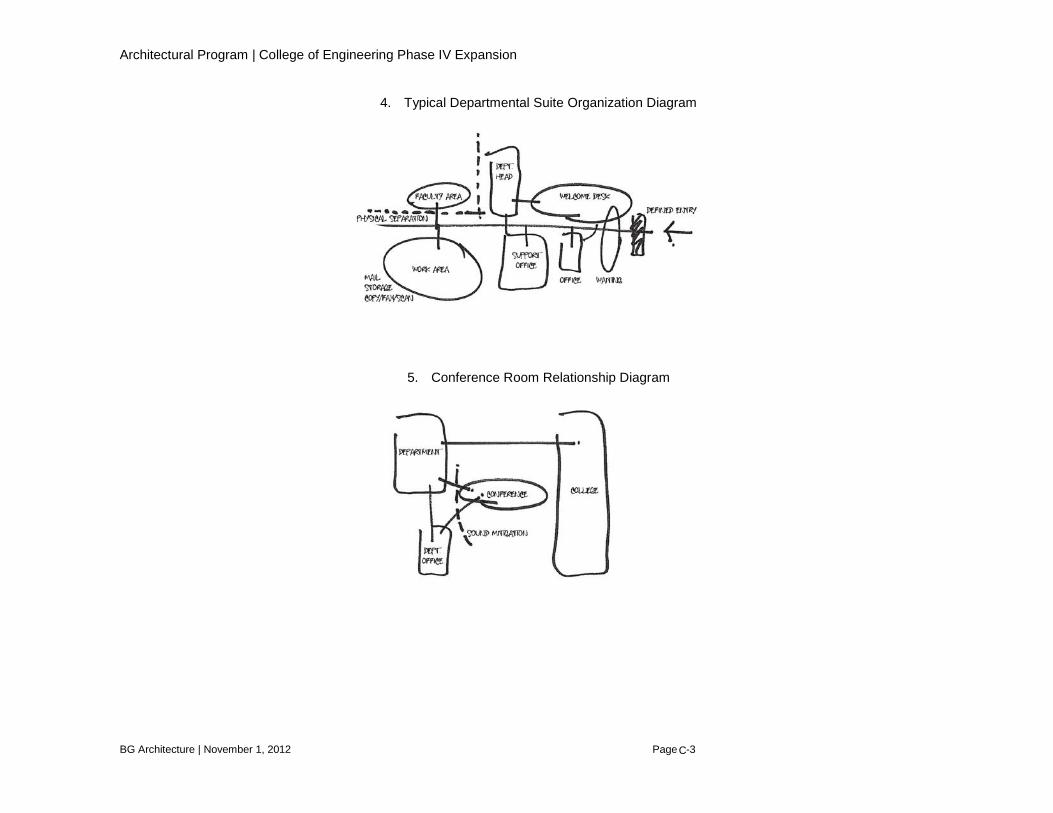
Architectural Program | College of Engineering Phase IV Expansion
BG Architecture | November 1, 2012 Page 8-3
4. Typical Departmental Suite Organization Diagram
5. Conference Room Relationship Diagram
C

Architectural Program | College of Engineering Phase IV Expansion
BG Architecture | November 1, 2012 Page 8-4
6. Typical Conference Room Organization Diagram
7. Typical Graduate Research Office Organization Diagram
C
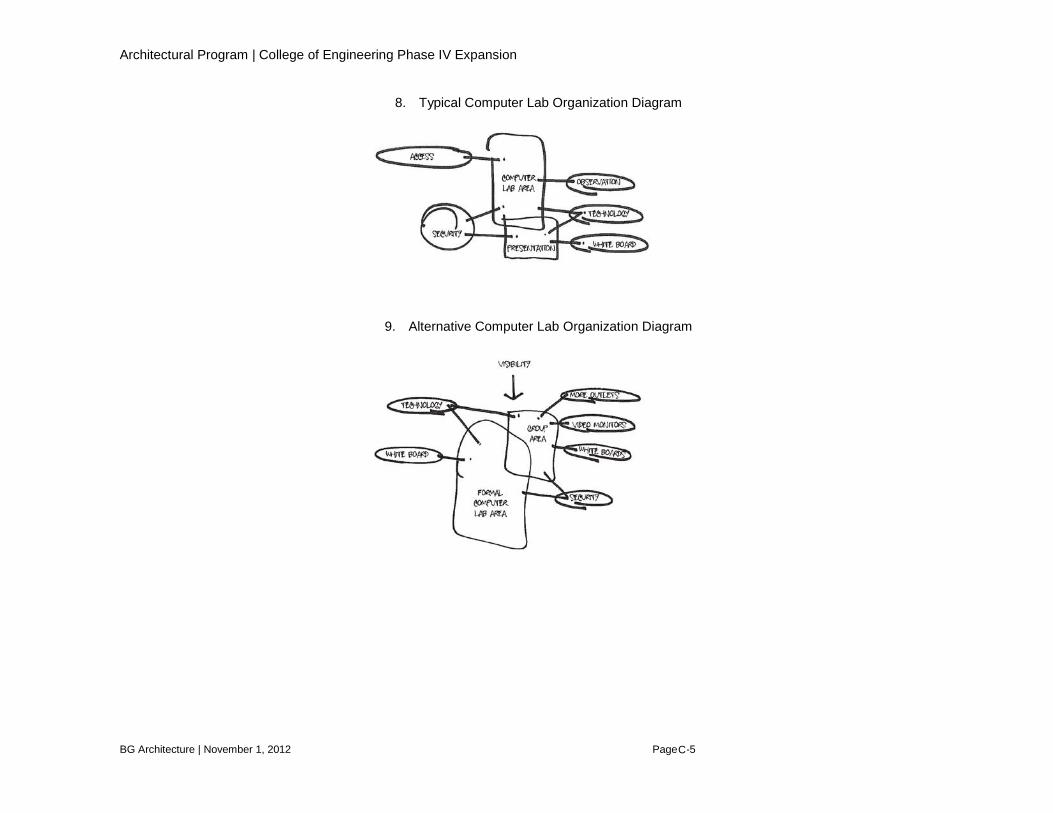
Architectural Program | College of Engineering Phase IV Expansion
BG Architecture | November 1, 2012 Page 8-5
8. Typical Computer Lab Organization Diagram
9. Alternative Computer Lab Organization Diagram
C
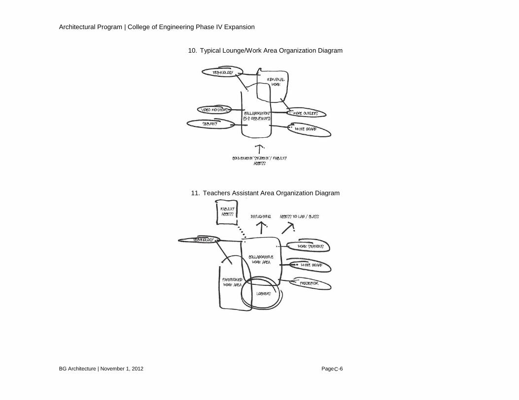
Architectural Program | College of Engineering Phase IV Expansion
BG Architecture | November 1, 2012 Page 8-6
10. Typical Lounge/Work Area Organization Diagram
11. Teachers Assistant Area Organization Diagram
C

Architectural Program | College of Engineering Phase IV Expansion
BG Architecture | November 1, 2012 Page 8-7
12. Biomed Research Labs Organization Diagram
C
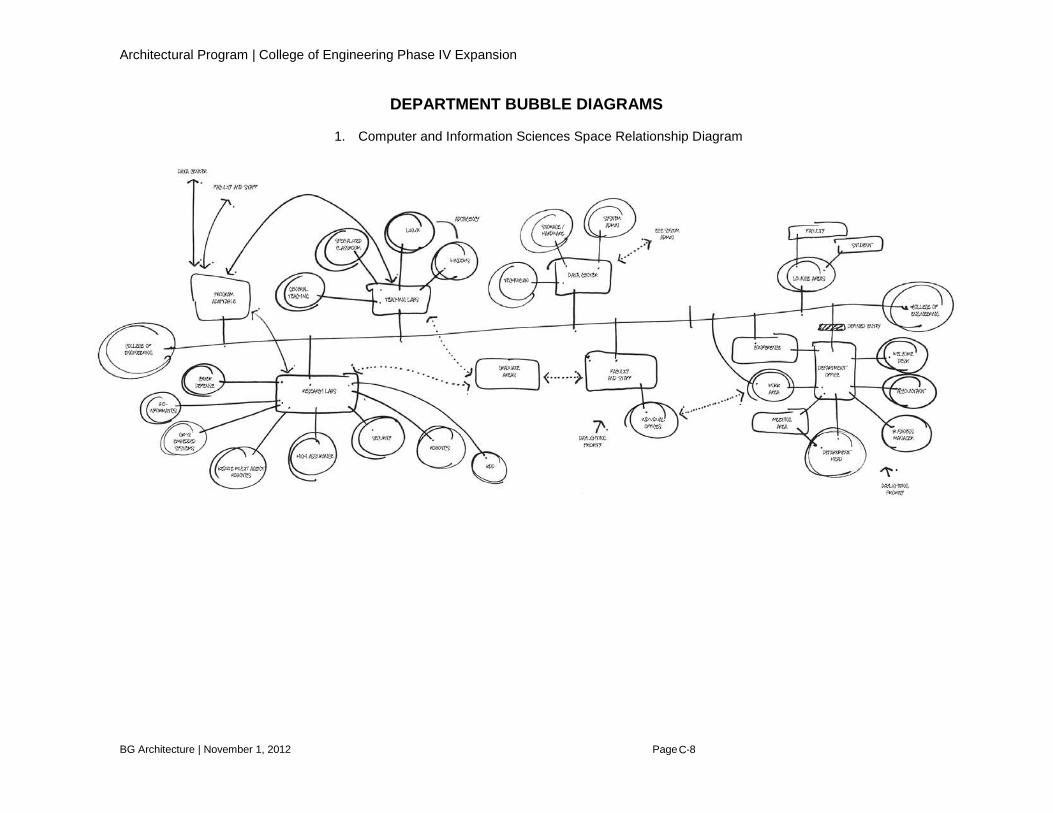
Architectural Program | College of Engineering Phase IV Expansion
BG Architecture | November 1, 2012 Page 8-8
DEPARTMENT BUBBLE DIAGRAMS
1. Computer and Information Sciences Space Relationship Diagram
C

Architectural Program | College of Engineering Phase IV Expansion
BG Architecture | November 1, 2012 Page 8-9
2. Electrical and Computer Engineering Space Relationship Diagram
C

Architectural Program | College of Engineering Phase IV Expansion
BG Architecture | November 1, 2012 Page 9-1
Appendix D The following section provides definitions of building area and definitions of space use codes. This appendix references the Postsecondary Education Facilities Inventory and Classification Manual (FICM) 2006. The following terms are defined and acronyms associated as used in the preceding text: Gross Area (GSF) Gross area is the sum of all areas on all floors of a building included within the outside faces of its exterior walls, including all vertical penetration areas, for circulation and shaft areas that connect one floor to another. This area is computed by physically measuring or scaling measurements from the outside faces of exterior walls, disregarding cornices, pilasters, buttresses, etc., that extend beyond the wall faces. Such area excludes light wells, or portions of upper floors eliminated by spaces or lobbies that rise above single-floor ceiling height. GSF = Net Usable Area + Structural Space Structural Area Structural area is the difference between the exterior or Gross Area and the interior or Net Usable Area, the floor area upon which the exterior and interior walls sit and the unusable areas in attics and excavated basements. Structural Area = Gross Area – Net Usable Area Net Usable Area Net usable area is defined as the aggregate interior area of a building and is the sum of the Assignable Area and Non-assignable area. Net Usable Area = Net Assignable Square Footage + Non-assignable Area Net Assignable Square Footage (NASF) Net assignable square feet (NASF) is the sum of floor space within interior walls of rooms that is assigned to, or available for assignment to, occupants for use, excluding non-assignable spaces defined as building service, circulation, mechanical, and structural areas. NASF is determined by Space Use Codes and Functional Category Code data fields. All rooms not specifically excluded are assignable and must be measured and coded according to academic discipline or administrative assignment (CIP), Space Use Codes, and Functional Category Codes. Rooms that are specifically excluded are Non-Assignable Areas. The 10 Major Assignable Space Use Categories are as follows: classrooms, laboratories, offices, study areas, special use space, general use areas, support rooms, health care, residential, and unclassified space. Net Assignable Square Footage = Sum of the 10 major Space Use Categories of Assignable Space
D
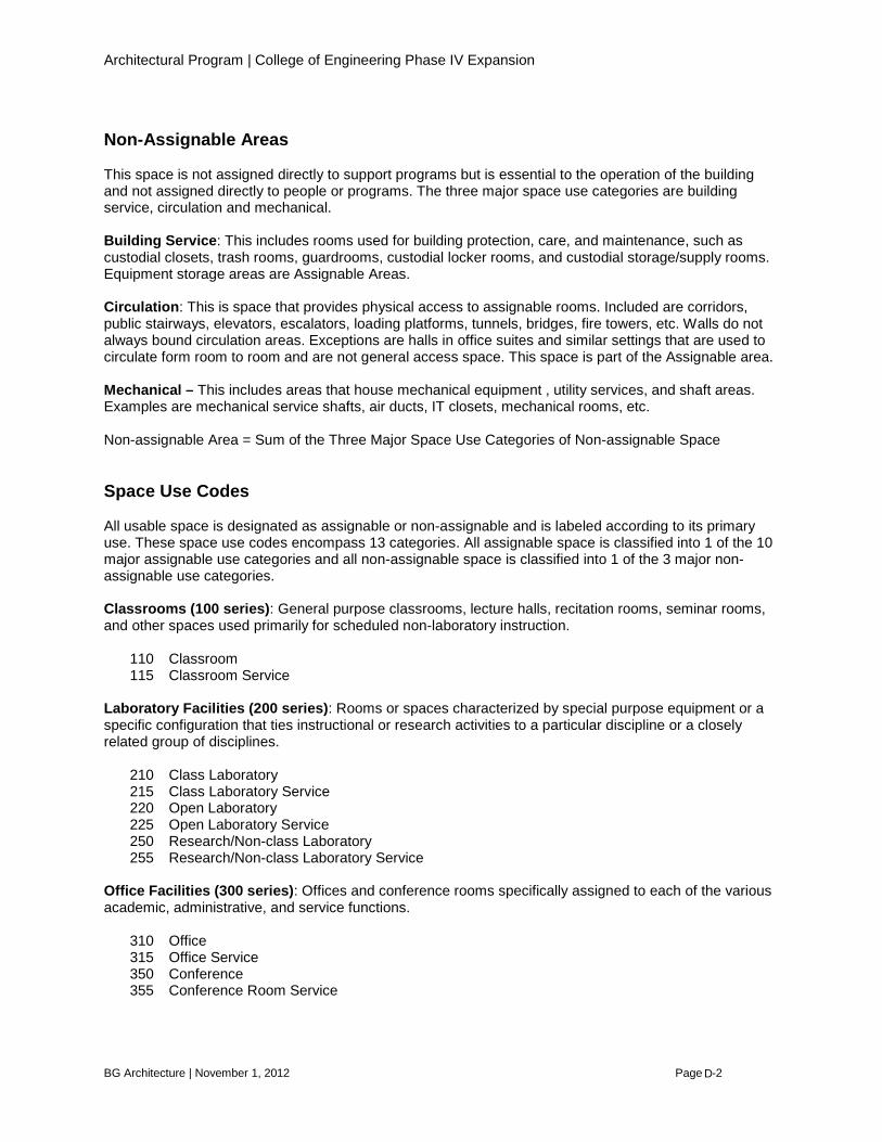
Architectural Program | College of Engineering Phase IV Expansion
BG Architecture | November 1, 2012 Page 9-2
Non-Assignable Areas This space is not assigned directly to support programs but is essential to the operation of the building and not assigned directly to people or programs. The three major space use categories are building service, circulation and mechanical. Building Service: This includes rooms used for building protection, care, and maintenance, such as custodial closets, trash rooms, guardrooms, custodial locker rooms, and custodial storage/supply rooms. Equipment storage areas are Assignable Areas. Circulation: This is space that provides physical access to assignable rooms. Included are corridors, public stairways, elevators, escalators, loading platforms, tunnels, bridges, fire towers, etc. Walls do not always bound circulation areas. Exceptions are halls in office suites and similar settings that are used to circulate form room to room and are not general access space. This space is part of the Assignable area. Mechanical – This includes areas that house mechanical equipment , utility services, and shaft areas. Examples are mechanical service shafts, air ducts, IT closets, mechanical rooms, etc. Non-assignable Area = Sum of the Three Major Space Use Categories of Non-assignable Space Space Use Codes All usable space is designated as assignable or non-assignable and is labeled according to its primary use. These space use codes encompass 13 categories. All assignable space is classified into 1 of the 10 major assignable use categories and all non-assignable space is classified into 1 of the 3 major non-assignable use categories. Classrooms (100 series): General purpose classrooms, lecture halls, recitation rooms, seminar rooms, and other spaces used primarily for scheduled non-laboratory instruction. 110 Classroom 115 Classroom Service Laboratory Facilities (200 series): Rooms or spaces characterized by special purpose equipment or a specific configuration that ties instructional or research activities to a particular discipline or a closely related group of disciplines. 210 Class Laboratory 215 Class Laboratory Service 220 Open Laboratory 225 Open Laboratory Service 250 Research/Non-class Laboratory 255 Research/Non-class Laboratory Service Office Facilities (300 series): Offices and conference rooms specifically assigned to each of the various academic, administrative, and service functions. 310 Office 315 Office Service 350 Conference 355 Conference Room Service
D

Architectural Program | College of Engineering Phase IV Expansion
BG Architecture | November 1, 2012 Page 9-3
Study Facilities (400 series): Study rooms, stacks, open-stack reading rooms, and library processing spaces. 400 Study Room Special Use Facilities (500 series): Military training rooms, athletic and physical education spaces, media production rooms, clinics, demonstration areas, field buildings, animal quarters, greenhouses, and other room categories that are sufficiently specialized in their primary activity or function to merit a unique room code. 530 Media Production 535 Media Production Service 590 Other (All Purpose) General Use Facilities (600 series): Assembly rooms, exhibition space, food facilities, lounges, merchandise facilities, recreational facilities, meeting rooms, child and adult care rooms, and other facilities that are characterized by a broader availability to faculty, students, staff, or the public than are special use areas. 630 Food Service 635 Food Facility Service 650 Lounge 680 Meeting Room 685 Meeting Room Service Support Facilities (700 series): Computing facilities, shops, central storage areas, vehicle storage areas, and central service space that provide centralized support for the facility. 710 Central Computer or Telecomm 715 Central Computer or Telecomm Serv 720 Shop 725 Shop Service 730 Central Storage 735 Central Storage Service 740 Vehicle Storage 745 Vehicle Storage Service 750 Central Service 755 Central Service Support 760 Hazardous Materials Storage 770 Hazardous Waste Storage 775 Hazardous Waste Service 780 Unit Storage Health Care Facilities (800 series): Not Used. Residential Facilities (900 series): Not Used. Non-assignable (000 series): Non-assignable spaces such as elevator, stairway, lobby, loading dock and other such space. 011 Bridge / Tunnel 012 Elevator
D

Architectural Program | College of Engineering Phase IV Expansion
BG Architecture | November 1, 2012 Page 9-4
013 Escalator 014 Loading Dock 015 Lobby 016 Public Corridor 017 Stairway 021 Custodial Supply Closet 022 Janitor Room 023 Public Rest Room 024 Trash Room 031 Central Utility Plant 032 Fuel Room 033 Shaft 034 Utility/Mechanical Space 036 Telecomm Closet Unclassified (000 series): Spaces available for assignment, temporarily out of use due to remodeling, or potentially assignable such as in new buildings or shell space 050 Inactive Area 060 Alteration or Conversion Area
70 Unfinished Area
D
Architectural Program | College of Engineering Phase IV Expansion
BG Architecture | November 1, 2012 Page 10-1
Appendix E As pressing demands for growth continue to impact the University, campus wide master planning will continue to organize future construction. Areas for circulation, parking, utilities infrastructure, and university buildings will continue to play an important dialogue in this planning effort. The areas proposed in the concept design are sensitive to University master planning issues and have been generally approved through consensus as appropriate for the College of Engineering Phase IV Expansion. Early evaluations of the site have revealed limitations in placement of the building expansion massing. The following diagrams serve as a graphic means to communicate the observations made at the time this program was developed and are intended to portray site limitations, opportunities, and constraints relevant to this project.
E
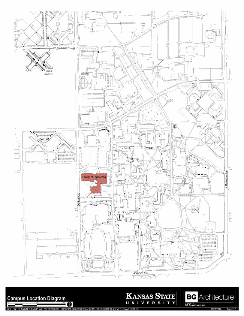
COLLEGE OF ENGINEERING PHASE IV EXPANSION | CONCEPT DESIGN OPTION; SOME PROGRAM REQUIREMENTS MAY CHANGE. 11/01/2012
4
3
4
3
0 500' 1000'
Campus Location Diagram
College of Engineering
Page E-2
Denis
on A
ve
Anderson Ave
N Ma
nhatt
an A
ve

COLLEGE OF ENGINEERING PHASE IV EXPANSION | CONCEPT DESIGN OPTION; SOME PROGRAM REQUIREMENTS MAY CHANGE. 11/01/2012
Fielder Hall
Rathbone Hall
Durland Hall
N. 17
th S
treet
Deni
son
Ave.
College Heights Road
Parking Lot
Existing Site DiagramPage E-3
0 8' 16' 32'
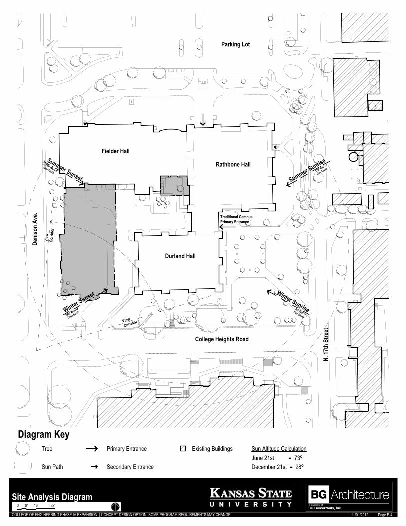
COLLEGE OF ENGINEERING PHASE IV EXPANSION | CONCEPT DESIGN OPTION; SOME PROGRAM REQUIREMENTS MAY CHANGE. 11/01/2012
Fielder Hall
Rathbone Hall
Durland Hall
N. 17
th S
treet
Deni
son
Ave.
College Heights Road
Parking Lot
Winter Sunset
Summer Sunset
Winter Sunrise
Summer Sunrise
View
Corri
dor
ViewCorridor
Traditional CampusPrimary Entrance
120º East of
Due South120º West of
Due South
60º East ofDue South
60º West of
Due South
Diagram KeyTree
Sun Path
Primary Entrance
Secondary EntranceJune 21st = 73ºDecember 21st = 28º
Sun Altitude CalculationExisting Buildings
Site Analysis DiagramPage E-4
0 8' 16' 32'

COLLEGE OF ENGINEERING PHASE IV EXPANSION | CONCEPT DESIGN OPTION; SOME PROGRAM REQUIREMENTS MAY CHANGE. 11/01/2012
Fielder Hall
Rathbone Hall
Durland Hall
N. 17
th S
treet
Deni
son
Ave.
College Heights Road
Parking Lot
Traditional CampusPrimary Entrance
Light Vehicle Traffic
Vehicle Traffic
Pedestrian Traffic
Bicycle Path
Parking
Diagram Key
Existing Buildings
Proposed Building
Site Circulation DiagramPage E-5
0 8' 16' 32'
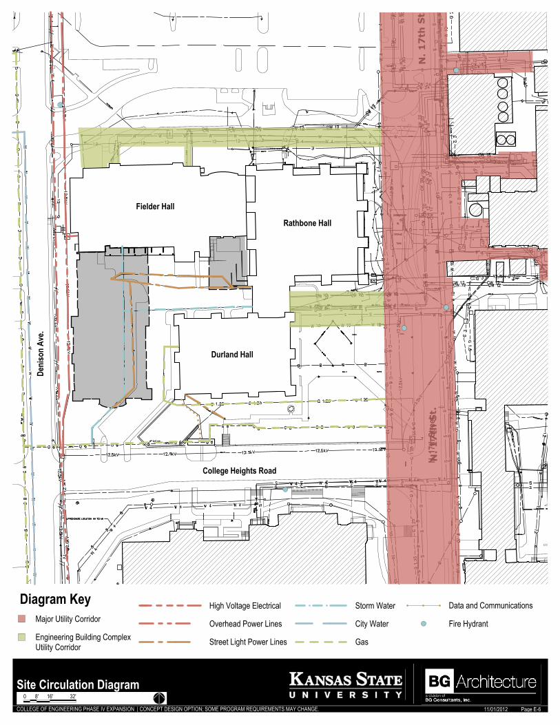
COLLEGE OF ENGINEERING PHASE IV EXPANSION | CONCEPT DESIGN OPTION; SOME PROGRAM REQUIREMENTS MAY CHANGE. 11/01/2012
N. 17
th S
treet
Deni
son
Ave.
Durland Hall
Rathbone Hall
Fielder Hall
College Heights Road
Major Utility Corridor
Engineering Building ComplexUtility Corridor
Diagram Key
Street Light Power Lines
Overhead Power Lines
Gas
Storm Water Data and Communications
City Water
High Voltage Electrical
Fire Hydrant
Site Circulation DiagramPage E-6
0 8' 16' 32'
Architectural Program | College of Engineering Phase IV Expansion
BG Architecture | November 1, 2012 Page 11-1
Appendix F The development of this program for the College of Engineering Phase IV Expansion has involved the collaboration of various people, representations and interests. Records of the meetings which established the cadence, requirements, and expectations for the expansion follow and are intended to serve as a basis for decisions made which have shaped the outcome of the programming initiative. All supporting documentation referenced in the meeting minutes and not included as a part of this document may be obtained from the Owner upon request.
F

Meeting Minutes
Project: College of Engineering Phase IV Expansion Architects Project #: 121217M Meeting Date: September 5, 2012 Location: 201 Dykstra Attendees: KSU Planning: David McMullen College of Engineering: Dave Fritchen BG Architecture: Tom Arpin, Clint Hibbs CC: The following summarizes key information provided and decisions made by the attendees listed above.
TOPICS
A. ct was defined: Re-Visit College of Engineering Phase IV Expansion Architectural Program submitted on April 6, 2012. Validate existing spaces to remain andprioritize space for Electrical and Computer Engineering and Computer and InformaSciences.
Purpose of Contra
tion
i. David McMullen explained the role of Bubble Diagrams as a tool in organizing the program spaces, adjacencies and relationships. These diagrams were to be used as a medium for communication and discussion in the development of the program.
ii. Discussion ensued about referencing building codes and standards, egress and accessibility as integral within the final program.
1. David mentioned that consideration should be given for life safety and describing it in the program.
B. Need for defining site limitations was discussed as a narrative, with supporting graphics. C. It was noted that the project delivery method may be Construction Manager at Risk. D. Part of the process of deliverables would be as follows:
i. (3) preliminary concept alternative solutions. ii. Then refining into (1) concept with images, floor plans, and numeric program.
E. It was stated that the architecture program would not require University dedicated instruction space.
F. The question was raised on how to address the vacated space currently housing ECE in Rathbone. Dave Fritchen clarified that that space would be noted only as vacated and re-allocation of those spaces would not be included as part of the Scope of Work for this project.
G. The budget was established at $40 million

i. Building occupancy is projected for 2015 and budget considerations should include escalation factor, as well as contingency for bidding and construction.
ii. Building will have a Honeywell Monitoring System/Controls. H. The program narrative should include a description of intent to tie into or be independent of
the existing university plant. i. Narrative should address systems. ii. No moneys should be invested in an MEP consultant at this stage for consultation. iii. BG Architecture should identify various problems, constraints and considerations.
I. Narrative should include general description of potential building structure. J. The next meeting was scheduled for October 5th at Seaton.
Clint Hibbs, AIA
NOTE: If the above information needs elaboration or clarification, please contact me within five (5) working days.
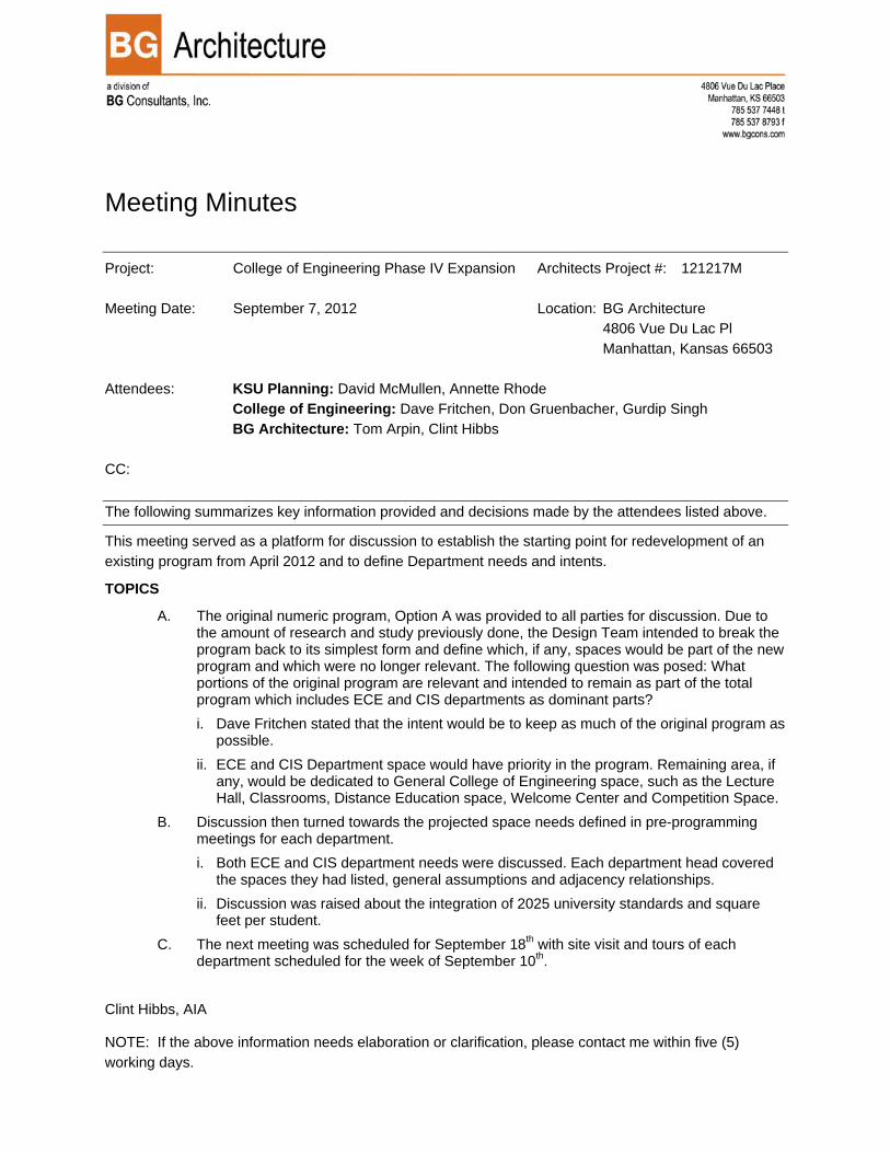
Meeting Minutes
Project: College of Engineering Phase IV Expansion Architects Project #: 121217M Meeting Date: September 7, 2012 Location: BG Architecture 4806 Vue Du Lac Pl Manhattan, Kansas 66503 Attendees: KSU Planning: David McMullen, Annette Rhode College of Engineering: Dave Fritchen, Don Gruenbacher, Gurdip Singh BG Architecture: Tom Arpin, Clint Hibbs CC: The following summarizes key information provided and decisions made by the attendees listed above.
This meeting served as a platform for discussion to establish the starting point for redevelopment of an existing program from April 2012 and to define Department needs and intents.
TOPICS
A. The original numeric program, Option A was provided to all parties for discussion. Due to the amount of research and study previously done, the Design Team intended to break the program back to its simplest form and define which, if any, spaces would be part of the new program and which were no longer relevant. The following question was posed: What portions of the original program are relevant and intended to remain as part of the total program which includes ECE and CIS departments as dominant parts? i. Dave Fritchen stated that the intent would be to keep as much of the original program as
possible. ii. ECE and CIS Department space would have priority in the program. Remaining area, if
any, would be dedicated to General College of Engineering space, such as the Lecture Hall, Classrooms, Distance Education space, Welcome Center and Competition Space.
B. Discussion then turned towards the projected space needs defined in pre-programming meetings for each department. i. Both ECE and CIS department needs were discussed. Each department head covered
the spaces they had listed, general assumptions and adjacency relationships. ii. Discussion was raised about the integration of 2025 university standards and square
feet per student. C. The next meeting was scheduled for September 18th with site visit and tours of each
department scheduled for the week of September 10th. Clint Hibbs, AIA
NOTE: If the above information needs elaboration or clarification, please contact me within five (5) working days.
Meeting Minutes
Project: College of Engineering Phase IV Expansion Project Number: 121217M Meeting Date: September 18, 2012 Location: Seaton 224 Conf. Rm. Attendees: KSU Planning: David McMullen, Annette Rohde College of Engineering: Dave Fritchen, Gurdip Singh, Don Gruenbacher Robert
Peterman BG Architecture: Tom Arpin, Clint Hibbs CC: The following summarizes key information provided and decisions made by the attendees listed above.
TOPICS
1. Clint provided an updated version of the numeric. A. General Academic Spaces
i. Clint will provide better clarification of the program headings for the next meeting. He will begin to generate a symbol and acronym table.
ii. Seminar space for CIS will require 24/7 access for students. iii. The competition space will be reduced to 7 spaces. The garage space can also be
reduced to allow the addition of a 3,000 Structural Lab in the lower level of the new addition.
iv. IT support space will be split into two areas. One area is for university use (25 sq. ft. each) and one for department use (100 sq. ft. per floor). It preferable to have these spaces stacked with corridor access.
v. Provide only one elevator to serve as both the public access and service access. Access to the roof may be required, but should have controlled access.
B. CIS Department Spaces i. ent head office should be 260 sf The departm
The conferen . es
r/Student Administrator space could be on a separate floor.
ogram. nd
space for the engineering departments. Only show the shell of the new space.
ii. ce room may be combined with the dept. of ECE. Requiring only oneC. ECE Department Spac
i. The System AdministratoD. David McMullen requested that all documents presented be dated and saved as an
appendix to the prE. David McMullen requested that the proposed wall layouts from the original program a
indicate only the available

contain a 3,000 sq. ft. structural lab.
The lab requi eiling clearance, the floor The lab ne
The structu h other departments and labs. The structu
ffices are required for this space. he propose sity
address the identity of the College of Engineering. e next m
IA,
e above inform me within five (5) orking days.
F. The College of Engineering wants to provide a structural lab in the lower level of the new addition.
i. New space to ii. Lab is to have concrete truck access. iii. res a minimum ceiling clearance of 12 feet. To achieve c
may be recessed. iv. eds to have sound isolation. v. A control room is required for the lab. This room should be dust resistant. vi. ral lab can share staging and loading areas witvii. ral floor is to have built in tie downs in sleeves. viii. 3 faculty o
G. T Welcome Center needs a name that does not conflict with the new univerwelcome center. It should
H. Th eeting will be held at Dykstra 201.
Tom Arpin A
NOTE: If th ation needs elaboration or clarification, please contactw
Meeting Minutes
Project: College of Engineering Phase IV Expansion Project Number: 121217M Meeting Date: September 25, 2012 Issue Date: September 26, 2012 Attendees: KSU Planning: Abe Fattaey, David McMullen, Annette Rohde
College of Engineering: Dave Fritchen, Gurdip Singh, Don Gruenbacher Robert Peterman
BG Architecture: Tom Arpin, Clint Hibbs CC: The following summarizes key information provided and decisions made by the attendees listed above.
TOPICS
1. Clint discussed the updated numeric program along with the description and explanation for the headings used in the various tables and charts
A. The “Garage” space is to be renamed “Central Support Space” (755). B. The square feet noted for the Lactation Room is to stay the same. The number of rooms
may fluctuate. The Lactation Room is to be private and lockable. It could possibly have multiple uses.
C. The “Clean Room” in the CE research spaces is to be renamed “Instrumentation Room”. D. The dept. head office for CIS is to be 260 square feet with the GSF changed to 377. E. A common conference space is desired between the lab spaces in CIS F. The staff offices in ECE are to have a wall 10.5 to 11 lineal feet to locate desk and work
stations on a single wall. G. The Bio-Prep lab is to be a common area for both the Medical Devices Lab and the
Bioinstrumentation Lab. H. Some labs require 240 volt three phase power. I. Appendix B (summary of space use category)
i. The categories are to be modified to reflect actual spaces in the program. i.e.: Conference Rooms, Competition Space, etc.
ii. Identify some of the spaces in the Non-Assignable space. i.e.: IT Rooms J. Abe indicated that the “Level of Construction” section needs to reflect complexity that will
result in higher construction costs for the infill space that affects multiple existing exterior surfaces. Provide a construction square foot cost for each “Level of Construction” item.
2. Clint presented options for space utilization for each floor.
One of th
It appears thaNatural lightin st
IT Room neThe structu
Abe
An exterior pi
A. The lower level containing Competition Space, Civil Engineering Structures Lab, storage, shop and mechanical space was presented.
i. e Competition Spaces will be for metal project and will require welding capabilities.
ii. t there will be anywhere from 5 to 7 Competition Spaces. iii. g need to be introduces wherever possible. Could be light well on the we
side of the proposed building. iv. eds to appear in conceptual drawings. v. ral lab needs 40 lin. ft. of Strong Wall. It is preferred that this wall is located
along two adjacent walls both 20 feet long creating a corner condition. The Strong Wall will be approximately 3 feet thick designed to withstand extreme horizontal forces.commented that this type of requirement will affect the sq. ft. cost of the Structural Lab. The structural lab also needs access to concrete delivery. Possibly an opening in the exterior wall to allow direct delivery of concrete.
vi. t approx. 10 feet by 10 feet with a sloped floor from 0 to 24 inches deep needs to be provided to clean out concrete equipment.
B. The first floor level containing the dept. of CIS was discussed. i. Discussion of the new connecting space between the existing spaces of Durland hall and
the new first floor space centered around having general academic spaces as a transition area or locating the department admin. suite in this space. One point brought up was general academic space in this area may lessen the student traffic thru the CIS department. This discussion also reflected the thoughts of the ECE department.
ii. The identity of the Department Administration Entrance needs a strong identity. iii. Faculty offices need to be located on the perimeter of the space to allow for natural
lighting. 3. Due to time constraints, the meeting needed to be concluded.
A. David McMullen commented during the presentation that all documents need to be dated and north arrows need to be added where applicable.
B. The time limit for future meetings is to be increased to 2 hours. C. The next meeting should have budget information available. D. The CIS and ECE department heads are to review the layouts provided by Clint and make
notes of characteristics that are acceptable or unacceptable for their departments.
Tom Arpin AIA,
NOTE: If the above information needs elaboration or clarification, please contact me within five (5) working days.
Engineers I Architects I Surveyors
Manhattan • Lawrence • Hutchinson • Emporia
Meeting Minutes
Project: College of Engineering Phase IV Expansion
Architects Project #: 121217M
Meeting Date: Tuesday, October 2, 2012 Issue Date: Thursday, November 01, 2012
Location: 201 Dykstra Hall
Attendees:
KSU Planning: David McMullen, Annette Rohde College of Engineering: Dave Fritchen, Ryan Benteman, Don Gruenbacher, Gurdip Singh BG Architecture: Tom Arpin, Clint Hibbs
CC: All parties.
This meeting was a regularly scheduled Programming work session meeting with the Architect, KSU Planning and College of Engineering.
Topics:
1. Annette road stated that the current University SF/person for instructional spaces was 22 SF/Person
a. BG requested that Planning resend University Standards for continuity and inclusion of values in program.
b. Dave McMullen stated that KSU Planning will evaluate the SF/person separate from this phase of programming and, as such, to help the College of Engineering and Departments assess the allocated SF/person. Such discussion can help guide the development of the expansion during the design and construction phase.
2. BG Architecture submitted past meeting minutes. It was requested that the minutes be provided to all participants via email in word format for editing as warranted. Future meeting notes were requested before each meeting for review.
3. Clint reviewed the updated numeric program. 4. Tom Arpin presented the initial budget for the building program. Discussion items were as follows:
a. At this stage of programming, items B and C in addition to F and G are to be combined within item A. Construction.
b. The Design fee associated with item H is to be set at this time to 7.5%. This value was agreed upon following a discussion about potential delivery methods.
c. The Contingency in item K is to be increased from 10% to 20%. d. Cost per square foot figures in items P‐R are to be clarified. A square foot cost of $310 could be
anticipated. The level of exterior finish will be affected if the estimated cost per square foot is not adequate.

Engineers I Architects I Surveyors
Manhattan • Lawrence • Hutchinson • Emporia
5. Clint presented draft diagrams indicating construction types, and other graphic information to be included as part of the building program submission. a. It was recommended that a diagram indicate areas allocated for CIS, ECE, CE, and general College of
Engineering areas, in addition to the hard‐lined drawings which will be prepared to show concept building layout.
6. Appendixes were discussed and reviewed: a. The Phase IV Expansion Summary, by space use category was discussed and relative percentages
considered. Itemization of a few items under various categories was recommended to be included. b. The written program was introduced and each department asked to review and delete, mark, and
modify each space and its requirements as appropriate. a. David McMullen requested that a general statement be included to address common and
global considerations such as air conditioning, accessibility, and so forth. b. It was agreed that the written program would be forwarded to each department for review
and revision in word format. c. Don Gruenbacher initiated discussion about how to best define graduate research areas in lieu of
currently assigned research. For example, the Sunflower Networking space will not always be used as it is currently designated and needs to be flexible to meet future graduate research needs. BG invited Don to review the spaces which and help clarify the program to represent the spaces for future use and not specifically defined per their current application.
d. David McMullen requested that the meeting notes be compiled within the appendixes. 7. BG led a brief discussion over the general organizational parti which will be used as a basis for the graphic
layout of the program. a. The arrangement of the lower level was reviewed. It was noted that the competition spaces were an
important part of the building program and that on the same level would be placed the structures lab and support spaces.
b. The main level would house CIS and the layout diagram prepared by Gurdip Singh and his department was reviewed, with College of Engineering general instructional spaces to the north.
c. The upper level would house ECE and the layout diagram was to be based upon option 1 presented during the previous meeting with College of Engineering general instructional spaces in the east expansion area.
d. It was requested that some offices be organized so that they would receive “borrowed” light from corridors along the exterior and that others be organized fully extended to the exterior wall.
e. Finally, discussion regarding the potential roof area needed for equipment and work area was defined as requiring 1000‐2000 sf. Approximately 500 sf dedicated to equipment and 1000 sf to work activities.
8. The next meeting was scheduled for October 9th. Deliverables anticipated are a complete draft of the written program, floor layout plans, and renderings.
Issued: BG Consultants, Inc.
By: Clint Hibbs AIA
Note: If the above information needs elaboration or clarification, please contact me within five (5) working days.
Engineers I Architects I Surveyors
Manhattan • Lawrence • Hutchinson • Emporia
Meeting Minutes
Project: College of Engineering Phase IV Expansion
Architects Project #: 121217M
Meeting Date: Tuesday, October 9, 2012 Issue Date: Friday October 12, 2012
Location: 201 Dykstra Hall
Attendees:
KSU Planning: David McMullen, Annette Rohde College of Engineering: Dave Fritchen, Bob Peterman, Jim Edgar, Brad Kramer, Don Gruenbacher, Gurdip Singh BG Architecture: Tom Arpin, Clint Hibbs
CC: All parties.
This meeting was a regularly scheduled Programming work session meeting with the Architect, KSU Planning and College of Engineering.
Topics:
1. Clint presented two options for concept layouts for each of the three floors outlining the College of Engineering Departments space and general College of Engineering space. The space allocations represent a graphic representation of the written and numeric program.
a. The Lower Floor Plan was reviewed. Option 1 was the preferred concept with the following modifications. i. The Student Shop and Central Support Space should be located adjacent to the Competition
Space. ii. The Program Adaptable Space for CIS should be located adjacent to the CIS labs. iii. The CE Structural Lab needs physical access to the corridor and loading area north of the lab.
The corridor needs to have direct access to the lab to allow the overhead crane the ability to move equipment and samples from the corridor level to the lower level of the lab. A removable safety rail will separate the corridor from the lab.
iv. Provide a platform lift from the corridor level to the Structural Lab floor. This lift could possibly be used for ADA access to the lab floor.
v. Move door access to east end of proposed building to allow full access between the corridor and Structural Lab. Provide an overhead door at this location.
b. David McMullen suggested the name of the engineering department should appear on the floor it is occupying. The Main Floor Plan will house CIS.
c. The Main Floor Plan concept options were presented. d. Gurdip preferred concept layout 2 with the following modifications.
i. The High Assurance Lab needs to be on this level.
Engineers I Architects I Surveyors
Manhattan • Lawrence • Hutchinson • Emporia
ii. It would be preferred to have the Departmental Suite located over the main south entry of the new phase four addition.
e. The 2nd Floor Plan concept options were presented. It was agreed that this floor will be referred to as the upper floor.
f. Don said he preferred option no. 2 for further development. The following modifications will be incorporated into this concept. i. The three offices for CE that will lose windows are to be located on this floor near the CE
Department. ii. Faculty offices should have exterior windows when possible. iii. The Chemical Engineering offices loosing windows need to be located in the new space or leave
daylight access to the window. iv. The Departmental Suite for ECE should be located in the same area of the Upper Floor as the
CIS Departmental Suite on the Main Floor. 2. Clint presented exterior rendering options depicting the massing of the exterior west and south
elevations and the vertical scale of the south entry element. 3. With the short time frame for developing the written and graphic program, the group decided to meet on
Friday October 12th at 8:30 am. at Dykstra 201.
By: Tom Arpin AIA
Note: If the above information needs elaboration or clarification, please contact me within five (5) working days.

Engineers I Architects I Surveyors
Manhattan • Lawrence • Hutchinson • Emporia
Meeting Minutes
Project: College of Engineering Phase IV Expansion
Architects Project #: 121217M
Meeting Date: Friday, October 12, 2012 Issue Date: Tuesday, October 16, 2012
Location: 201 Dykstra Hall
Attendees: KSU Planning: David McMullen, Annette Rohde College of Engineering: Dave Fritchen, Brad Kramer, Don Gruenbacher, Gurdip Singh BG Architecture: Tom Arpin, Clint Hibbs
CC: All parties.
This special meeting was scheduled so supplement the regularly scheduled Programming work session meetings with the Architect, KSU Planning and College of Engineering.
Topics:
1. Clint presented the latest concept layouts for each of the three floors outlining the College of Engineering Departments space and general College of Engineering space. The space allocations represent a graphic representation of the written and numeric program.
a. David McMullen suggested the exterior opening and floors have an elevation reference to illustrate the vertical differences on these levels.
b. Mechanical and storage space will be evaluated and determined during the program validation task of the next architectural design team.`
c. The Lower Floor Plan was reviewed. The following areas were discussed. i. The loading dock should be located on the east side of the lower level floor with access to the
center corridor. Trucks would be able to back into the dock from the College Heights. ii. The remainder of the lower level plan was in conformance with the written program and was
acceptable to the group. d. On future drawing, the college departments in Fiedler and Durland Halls will be noted in the spaces
they occupy adjacent to the Phase IV addition. Also note landmark spaces ie: Fiedler Auditorium, College of Engineering Offices, etc.
e. The Main Floor Plan was reviewed. The following areas were discussed. i. Gurdip suggested flipping the college program spaces north to south. He also suggested flipping
the general college spaces with the CIS space to the west. ii. Gurdip also requested offices with exterior window. iii. Move the Security Lab, Teaching Lab and KDD Lab to the northeast against the north and east
wall of the addition creating a corridor. iv. Provide a north south corridor through the main area of CIS labs. This corridor will provide
access from the north general college spaces and the Departmental Offices.
Engineers I Architects I Surveyors
Manhattan • Lawrence • Hutchinson • Emporia
v. The Serpan Lobby should be relocated to the east entry of the new Lecture Hall. f. Clint advised the group that he would add the access arrow designation to the Floor Plan Key. g. The Upper Floor Plan was reviewed. The following areas were discussed.
i. Don said he needs 10 2‐person offices and 4 4‐person offices for grad assistants. ii. The Department Lounge for ECE needs to be adjacent to the Departmental Suite. If possible,
stack with CIS Department Lounge iii. Correct spelling for Communications Circuits Lab. iv. Provide a Wireless Hardware Lab.
h. The 2nd Floor Plan concept options were presented. It was agreed that this floor will be referred to as the upper floor.
i. Don said he preferred option no. 2 for further development. The following modifications will be incorporated into this concept. i. The three offices for CE that will lose windows are to be located on this floor near the CE
Department. ii. Faculty offices should have exterior windows when possible. iii. The Chemical Engineering offices loosing windows need to be located in the new space or leave
daylight access to the window. iv. The Departmental Suite for ECE should be located in the same area of the Upper Floor as the
CIS Departmental Suite on the Main Floor. j. Clint presented the west (Denison Avenue) and south (College Heights Road) elevations.
i. Add the stair and elevator penthouse to the elevations. ii. Show the floor vertical elevations in relation to the ground level. iii. The bridge section of the link between Phase VI and Durland Hall shall have 14 feet of vertical
clearance. iv. Designate new construction from existing construction.
2. The group reviewed the latest exterior rendering and is in agreement with the current appearance.
By: Tom Arpin AIA
Note: If the above information needs elaboration or clarification, please contact me within five (5) working days.

Engineers I Architects I Surveyors
Manhattan • Lawrence • Hutchinson • Emporia
Meeting Minutes
Project: College of Engineering Phase IV Expansion
Architects Project #: 121217M
Meeting Date: Tuesday, October 16, 2012 Issue Date: Friday, October 19, 2012
Location: 201 Dykstra Hall
Attendees: KSU Planning: David McMullen, College of Engineering: Dave Fritchen, BG Architecture: Tom Arpin, Clint Hibbs
CC: All parties.
This meeting was a regularly scheduled Programming work session meeting with the Architect, KSU Planning and College of Engineering.
Topics:
1. Clint presented the Expansion Diagrams illustrating the new construction, infill construction and Renovation Construction for each of the three floors of the Phase IV expansion to the College of Engineering. The bottom of each sheet is to read “some program requirements may change”.
2. David McMullen commented that this building will be type 1 fully sprinkled. He also said that the 2010 ADA requirements will govern this project.
3. The Upper Floor Expansion Diagram shall show the GSF of eh vacated ECE space is “For Reference Information Only”. Align the 20,623 GSF number with the Space Vacated line.
4. Clint reviewed the latest concept layouts of each floor. a. The Lower Floor Plan review comments are as follows:
i. The floor of the Structures Lab will be 4 to 6 feet below the floor level of the lower floor. This is to allow a 14’‐6” clearance from the floor to the crane pick point.
ii. Robert Peterman from the Dept. of Civil Engineering oversees the current structural labs and presented an email to Clint detailing programming requirements for the CE space in the lower level. These requirements will be incorporated into the written program.
iii. Show the floor elevation difference between the three CE rooms adjacent to the Structural Lab and the Structural Lab Floor.
iv. Label the structure limit for the overhead structure of the Main Floor structure. v. Drainage of the pavement in the enclosed center area of the engineering complex is an issue
that needs strong attention in the program validation phase of the design contract. vi. It will be important to assess the material deposited in the concrete wash pit to determine the
drainage system. b. The Main Floor Plan was reviewed. The following areas were discussed.
Engineers I Architects I Surveyors
Manhattan • Lawrence • Hutchinson • Emporia
i. Provide the north/south corridor adjacent to Cyber Defense. ii. Move the College Classroom to the south to eliminate the “dead‐end corridor”. iii. The west wall adjacent to the General College Space can be moved a few to the west in order to
accommodate a more efficient space layout. iv. Correct the spelling for Paslay Auditorium.
c. There were no exceptions to the Upper Floor Plan as presented. d. Clint reviewed the latest building elevations.
i. David McMullen does not want pine trees to be illustrated on the elevations. ii. The floor elevations shown are in relation to the elevation of the floors of the existing buildings.
5. The group reviewed the latest exterior rendering and is in agreement with the current appearance. 6. The group decided a special meeting needs to take place Friday afternoon October 19th at 1:30 pm.
By: Tom Arpin AIA
Note: If the above information needs elaboration or clarification, please contact me within five (5) working days.

Engineers I Architects I Surveyors
Manhattan • Lawrence • Hutchinson • Emporia
Meeting Minutes
Project: College of Engineering Phase IV Expansion
Architects Project #: 121217M
Meeting Date: Friday, October 19, 2012 Issue Date: Tuesday, October 23, 2012
Location: 201 Dykstra Hall
Attendees:
KSU Planning: David McMullen, College of Engineering: Dave Fritchen, Jim Edgar, Brad Kramer, Don Fenton, Don Gruenbacher, Gurdip Singh BG Architecture: Tom Arpin, Clint Hibbs
CC: All parties.
This special meeting was scheduled so supplement the regularly scheduled Programming work session meetings with the Architect, KSU Planning and College of Engineering.
Topics:
1. Clint provided Dave Fritchen and David McMullen hard copies and a cd with the latest concept drawings. Dave Fritchen indicated the material presented is adequate for his upcoming presentation to the College of Engineering Advisory Board.
2. Dave Fritchen and David McMullen agreed that the cost of landscaping is not a part of this programming effort.
3. Review of the presented concept drawings produced the following comments: a. David McMullen suggested moving the spot elevation designations closer to the building openings. b. Label the reaction wall in the Structural Lab. c. Include a requirement for a “Glycol” System for the loading dock ramp in the written program. d. Correct the spelling of Maintenance in the Diagram Key. e. Provide physical and visual access between the Lecture Hall and Large Conference Room. f. Incorporate the dead end corridor space at the north end of the Upper floor to the north office space.
2. System analysis of the existing utilities will be part of the program validation phase. 3. The group approved the exterior rendering and building elevations. 4. Changes to the drawing will be completed and submitted early next week.
By: Tom Arpin AIA
Note: If the above information needs elaboration or clarification, please contact me within five (5) working days.