
Collaborative Manufacturing Network for Competitive Advantage
54
284928 Collaborative Manufacturing Network for Competitive Advantage D8.2.1 – Mobiel Maintenance Adaption of Secure Information Model Concept (public)
Transcript of Collaborative Manufacturing Network for Competitive Advantage

284928
Collaborative Manufacturing Network
for Competitive Advantage
D8.2.1 – Mobiel Maintenance
Adaption of Secure Information Model Concept
(public)

D8.2.1 – Adaption of Secure Information Model Concept
WP 8 – Mobile Maintenance
© ComVantage Consortium – 2012 2
Grant Agreement No. 284928
Project acronym ComVantage
Project title Collaborative Manufacturing Network for Competitive Advantage
Deliverable number D8.2.1
Deliverable name Adaption of Secure Information Model Concept
Version V 1.0
Work package WP 8 – Mobile Maintenance
Lead beneficiary UNIVIE
Authors Dimitris Karagiannis (UNIVIE), Robert Buchmann (UNIVIE), Patrik Burzynski (UNIVIE), Jasmin Brakmic (UNIVIE), Oscar Lazaro (INNO), Patricia Ortiz (INNO), Manuel Carnerero (NEXTEL)
Reviewers David Orensanz (BOC-IB), Georg Süß (K&A)
Nature R – Report
Dissemination level PU – Public
Delivery date 31/10/2012 (M14)

D8.2.1 – Adaption of Secure Information Model Concept
WP 8 – Mobile Maintenance
© ComVantage Consortium – 2012 3
Executive Summary This report presents specific adaptations of generic concepts developed within work package 3, according to specificities of the application area Mobile Maintenance. It is the first iteration of two and it contributes as a direct input document for the implementation phases to be developed in tasks 3.3 and 3.4.
For task 3.3, it must be read as an extension to deliverable D3.2.1, as it adds details to the security conceptual framework approach, with respect to the Mobile Maintenance application area.
For task 3.4, it must be read as a continuation to deliverable D3.1.1, as it extends the generic ComVantage modelling method with model types and modelling elements that are specifically designed for this application area. The extensions described are: a model type for defect design and maintenance process assignment; model types for service level agreements and skill requirements; an enrichment of the mobile mockup model type towards a more abstract modelling of apps; the SIPOT model type for expressing data requirements along a process path.

D8.2.1 – Adaption of Secure Information Model Concept
WP 8 – Mobile Maintenance
© ComVantage Consortium – 2012 4
Table of Contents
1 OVERVIEW ..................................................................................................................................... 7
1.1 INTRODUCTION .................................................................................................................................... 7
1.2 SCOPE OF THIS DOCUMENT .................................................................................................................... 7
1.3 RELATED DOCUMENTS ........................................................................................................................... 8
1.4 TERMS AND ACRONYMS USED IN THIS DOCUMENT ..................................................................................... 9
2 COMVANTAGE MODELLING METHOD ADAPTATIONS .................................................................... 10
2.1 OVERVIEW OF THE COMVANTAGE METAMODELLING APPROACH ................................................................ 10
2.2 ADAPTED MODEL TYPES ...................................................................................................................... 12
2.2.1 The Process Model Type........................................................................................................ 12
2.2.2 The Mobile Orchestration Model Type ................................................................................. 18
2.2.3 The Mobile Mockup Model Type .......................................................................................... 18
2.2.4 The Organisational Structure Model Type ............................................................................ 25
2.2.5 General Classes and Attributes ............................................................................................. 25
2.3 NEW MODEL TYPES ............................................................................................................................ 25
2.3.1 The Machine State Model Type ............................................................................................ 25
2.3.2 The SLA Model Type .............................................................................................................. 32
2.3.3 The Skill Model Type ............................................................................................................. 38
2.3.4 The SIPOT Process Model Type ............................................................................................. 42
3 THE SECURITY FRAMEWORK ADAPTATIONS .................................................................................. 49
3.1 THE MULTI-TIERED ACCESS CONTROL ARCHITECTURE ............................................................................... 49
3.2 OTHER REQUIRED COMPONENTS .......................................................................................................... 50
3.3 ADAPTATION OF THE SECURITY MODEL TO THE WP8 APPLICATION AREA .................................................... 50
4 CONCLUSION AND OUTLOOK........................................................................................................ 52
4.1 CONCLUSIONS .................................................................................................................................... 52
4.2 OUTLOOK AND OPEN ISSUES ................................................................................................................ 52
5 REFERENCES ................................................................................................................................. 53

D8.2.1 – Adaption of Secure Information Model Concept
WP 8 – Mobile Maintenance
© ComVantage Consortium – 2012 5
List of Figures
Figure 1: Positioning of the current document in the ComVantage task flow .................................................. 8
Figure 2: Overview of the ComVantage modelling stack (v 1+) ...................................................................... 10
Figure 3: WP8 extensions to the conceptual landscape of D3.1.1 .................................................................. 11
Figure 4: Integration of the Interaction flow level ........................................................................................... 13
Figure 5: Example path used for SIPOT generation ......................................................................................... 16
Figure 6: Automatically generated SIPOT model for example path ................................................................ 17
Figure 7: Manually extended SIPOT model example....................................................................................... 17
Figure 8: Example of Mobile mockup model, based on an example of the Project partners TU Dresden, SAP Research Dresden. .................................................................................................................................. 19
Figure 9: Pearson's product-moment coefficient. ........................................................................................... 24
Figure 10: Example for Mobile mockup comparison....................................................................................... 24
Figure 11: Machine state model example for a printer type .......................................................................... 26
Figure 12: Example SLA model ........................................................................................................................ 32
Figure 13: Example for visualising SLA compliance ......................................................................................... 37
Figure 14: Example for a Skill model ............................................................................................................... 39
Figure 15: Defined Skill profiles and defined references to Performer and Role. ........................................... 39
Figure 16: Comparison of available and required skills. .................................................................................. 41
Figure 17: Example for a SIPOT model ............................................................................................................ 43
Figure 18: Multi-tiered access control architecture ........................................................................................ 49

D8.2.1 – Adaption of Secure Information Model Concept
WP 8 – Mobile Maintenance
© ComVantage Consortium – 2012 6
List of Tables
Table 1: Security questionnaire ....................................................................................................................... 51
Table 2: Security questionnaire for prototype implementation ..................................................................... 51

D8.2.1 – Adaption of Secure Information Model Concept
WP 8 – Mobile Maintenance
© ComVantage Consortium – 2012 7
1 OVERVIEW
1.1 Introduction
This is the first iteration (of two) of a deliverable whose goal is to adapt the generic results of WP3 to the specific context of the Mobile Maintenance application area. Thus, the document places emphasis on the newly added or modified aspects, while the methodological background of the issues under scrutiny (the security framework for Linked Data and the modelling method development framework) will be mentioned only briefly (and referred to the generic deliverables).
The document is organised as follows: this introduction is followed by a scope statement and document positioning in the flow of deliverables, then a list of terms and acronyms used in the document. Chapter 2 starts with a brief introductory reference to the generic modelling method specified in D3.1.1. The chapter continues with the specification of the extensions and adaptations determined by the WP8 context, to be considered as an addendum to the specification presented in D3.1.1. Chapter 3 provides details regarding the adaptation approach for the security framework described in D3.2.1. The document ends with conclusions and an outlook to future developments envisioned for the second iteration.
1.2 Scope of this Document
According to the description of work, "Based on the generic concepts of the secure information model (WP 3) modifications and extensions required for this application area will be conducted". More specifically, activities performed in this task will cover two basic aspects:
Adaptation and validation of the modelling method;
Adaptation and validation of the secure access model.
Due to similarities in context, approach and structure, certain introductory sections (sections 1 and 2.1) will be partly similar to the corresponding ones in parallel deliverables (D6.2.1, D7.2.1), with some cues regarding what specificities are covered by the current document. The overlapping is minimised, but necessary to improve readability of the document as a standalone one, and to place the content of the current deliverable in context. Additionally, cross references to the parallel deliverables may occur, where certain aspects are considered applicable in other application work packages as well.
Chapter 2 comprises the changes and additions to the ComVantage modelling stack, following the same metamodelling approach as the generic specification (D3.1.1):
Model mockups are be used to emphasise the role of the new modelling elements in the context;
Sections of formal specifications must be considered as addendum to the D3.1.1 generic specification, thus as direct input to the modelling tool implementation. They specify which existing model types are affected by changes and which are the additional model types. An updated view of the extended conceptual landscape is also provided.
With regard to the modelling method validation, this will be performed based on direct interaction with the modelling tool, as part of tasks 3.4 and the next iteration in the current task (8.2) and will cover the following validation layers:
Conceptual validation: if the domain is properly covered by the modelling constructs and their semantics, if missing concepts are identified, if the modelling language is visually expressive;
Software validation: if the modelling tool supports the conceptual coverage in a usable way;
Procedure validation: if the usage procedure required to design a full model set, expressing a given scenario, is well assimilated by the end-user and well supported by the tool.
With regard to the security approach, the adaptation process is as follows. Based on the security concept defined in D3.2.1 a common set of elements for a secure multi-domain collaboration needs to be defined. For each application area, such model need to be put in context so that the ComVantage multi-domain

D8.2.1 – Adaption of Secure Information Model Concept
WP 8 – Mobile Maintenance
© ComVantage Consortium – 2012 8
access control model can be connected with the individual information security mechanisms deployed by each domain. The identification of the link and interaction between the traditional security measures deployed by each cases and the ComVantage security model defined in D3.2.1 will therefore be the focus of the document. To this purpose, the specific security mechanisms, data sources and collaboration contexts and procedures will be made more explicit.
1.3 Related Documents
The current document's position in the project context and with respect to related deliverables and tasks is presented in Figure 1. The relations expressed in the figure are as follows:
Application areas' refined scenarios provide the starting point for identifying decisions in processes and opportunities to be supported by models;
The generic modelling method from D3.1.1. and the generic security framework from D3.2.1 are refined and extended in accordance to the specific contexts of WP6, WP7 and WP8;
Ontologies developed for the Adaptation of Linked Data integration contain a conceptual view which also provided input the current document conceptualisation. This allowed deriving and refining concepts for the application area specific adaptations.
Both the generic concepts and the adaptations are direct input to the implementation tasks in WP3 (tasks 3.3 and 3.4);
All adaptation deliverables reference each other in certain aspects. Although their content is aligned to their respective contexts, certain aspects are cross-referenced with deliverables 6.2.1 and 7.2.1 to suggest dependencies or the complementarity of these approaches. Particularly for purposes of implementing the modelling tool, all three adaptation deliverables should be read together.
Figure 1: Positioning of the current document in the ComVantage task flow

D8.2.1 – Adaption of Secure Information Model Concept
WP 8 – Mobile Maintenance
© ComVantage Consortium – 2012 9
1.4 Terms and Acronyms Used in this Document
Abstract user interface – a user interface described in terms of its structure and goals rather than look and feel
D3.1.1 – Specification of Modelling Method Including Conceptualisation Outline
D3.2.1 – ComVantage Secure Information Model Definition
D5.3.1 – UI Modelling and Generation Framework
D6.2.1 – Plant Engineering and Commissioning – Adaption of Secure Information Model Concept
D7.2.1 – Customer-oriented Production – Adaption of Secure Information Model Concept
D8.2.1 – Mobile Maintenance – Adaption of Secure Information Model Concept
D8.2.2 – Mobile Maintenance – Adaption of Secure Information Model Concept (2nd iteration)
IT – Information technology
Lean – process control strategy aimed to minimise waste
Linked Data – a way of expressing and publishing data using the RDF data model
Metamodel – a specification that describes what are the allowed elements and how can they be used in creating models
MM – Modelling method
Model – for the purposes of this deliverable, we refer to conceptual modelling, with models being instances of the DKE metamodelling framework (presented in D3.1.1)
Modelling procedure – a set of modelling steps driven by modelling goals in specific scenarios
POI – "Point of interaction", working term used to express an abstract user interface element that captures a requirement for user interaction
RDF – Resource Description Framework
SCOR – Supply Chain Operations Reference
SIPOT – Derived from SIPOC (Supplier, Input, Process, Output, Customer), a sequential description of activities/tasks focusing on five aspects: Source, Input, Process, Output, Target
SLA – Service Level Agreement
SPARQL – the standard language for querying Linked Data expressed as RDF
UI – User Interface
WP – Work package
D8.2.1 – Adaption of Secure Information Model Concept
WP 8 – Mobile Maintenance
© ComVantage Consortium – 2012 10
2 COMVANTAGE MODELLING METHOD ADAPTATIONS
2.1 Overview of the ComVantage Metamodelling Approach
This section serves as a brief bridge between D3.1.1. and the modelling method adaptation deliverables, thus it will be reproduced in D6.2.1, D7.2.1 and D8.2.1 to improve the readability. Thus the adaptations envisioned by the current deliverable will be highlighted in context, as applicable.
The ComVantage Modelling Method has been developed on a metamodelling framework according to (Karagiannis and Kühn, 2002) which defines a modelling method as being composed of:
Modelling language – the modelling constructs and their semantics;
Modelling procedure – the steps required to perform the modelling;
Model-level functionality – mechanisms and algorithms for model visualisation, querying, simulation, transformation.
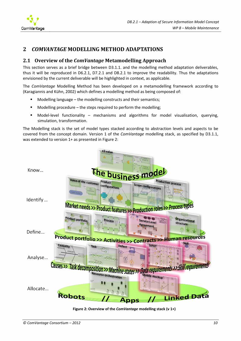
The Modelling stack is the set of model types stacked according to abstraction levels and aspects to be covered from the concept domain. Version 1 of the ComVantage modelling stack, as specified by D3.1.1, was extended to version 1+ as presented in Figure 2:
Figure 2: Overview of the ComVantage modelling stack (v 1+)

D8.2.1 – Adaption of secure information model concept
WP 8 – Mobile Maintenance
© ComVantage Consortium – 2012 11
Figure 3: WP8 extensions to the conceptual landscape of D3.1.1
D8.2.1 – Adaption of secure information model concept
WP 8 – Mobile Maintenance
© ComVantage Consortium – 2012 12
The current deliverable is one of the three deliverables that specify changes and extensions to the modelling method. The areas affected by the additions brought by the current deliverables are highlighted (in red) in the new modelling stack, Figure 2, and in the conceptual landscape of the method, Figure 3, which extends the one presented in D3.1.1. The adaptations targeted for this deliverable also considered theoretical approaches to maintenance management frameworks available in the literature (Márquez, 2010). The specific additions are as follows:
support for defect design mapped on maintenance and testing processes;
support for expressing skills for experts involved in maintenance; the skills can be split in two categories: required and available, then matched against each other;
support for expressing service level agreements in a structured way, which opens possibilities for matching their quantitative terms (price, validity, quantitative goals) against potential run-time data;
support for mapping the data and mobile app requirements along a selected path of a process;
a rethinking the mobile support models in terms of requirements for supporting a certain process rather than a way of indicating possible UI elements, using elements which are called in the current document "points of interaction".
Changes to the generic Modelling Method specified in D3.1.1 are presented in this chapter. Several rules on how those changes should be handled (unless stated otherwise) are, as follows:
Classes with the same name as in D3.1.1 should be reused, meaning they represent the same things. This can either be for the sake of reuse in new model types or to change (extend or restrict) the characteristics described in D3.1.1 or both. If a class is reused then all the attributes it should provide are specified here, meaning that missing attributes should be removed.
New classes are introduced here and use different names than the ones from D3.1.1. They can appear in already established model types extending those as well as in the newly described model types.
Old classes and model types should be kept and integrated with the here specified changes, unless stated otherwise. The same holds true for Constraints and Mechanisms/Algorithms.
o The constraints regarding cardinality of relation classes are now specified directly in the Relation Class tables instead of the previous specification under Constraints. They generally follow the form of “Cardinality: X to Y” where Y specifies the maximum limit for the amount of targets and X the maximum limit for the amount of sources to which the elements from “FROM” and “TO” can be connected. Still relations are considered to be binary, meaning that one relation always connects only one source to one target element.
For several relations no notation has been envisioned by the authors, since it is not deemed necessary to visualise them in those specific model types. Some relation classes without notation should contain attribute values. However since they are not visible in the model their attributes have to be represented somewhere else. In this case they should be accessible through the source element (similar to its attributes) and can be implemented as a table where a row contains the relation and the according attribute values.
2.2 Adapted Model Types
2.2.1 The Process Model Type1
In order to allow the modelling of interaction for Mobile support features and their Mobile mockups levels for the Process model type are introduced. Those are the business level, the technical level and the Interaction flow level. On the business level the business processes are described. The technical level
1 Additional adaptations of this model type have been specified in D6.2.1 and D7.2.1

D8.2.1 – Adaption of secure information model concept
WP 8 – Mobile Maintenance
© ComVantage Consortium – 2012 13
further details how a business process should be executed in a technical environment. The interaction flow level further details how the user should interact with an app or software. Therefore, the interaction flow can be seen as an intermediate level between the other two process levels (technical/business level) and the Mobile mockup model as shown in Figure 4. The individual Activities of the interaction flow level processes are linked to the individual Points of interaction of a Screen in a Mobile mockup model indicating on what parts they work. The type of interaction can be derived from the type of the POI (like Readable or Interactive), but should also be provided in the name of the Activity when modelling.
Figure 4: Integration of the Interaction flow level
Classes and attributes:
1. The Sub-process is removed and instead merged into the normal Activity.
Model Attributes (of a Process model)
Attribute name Type Description
Level Enumeration Specify the level which this process describes. Can be one of: a) Business level, b) Technical level or c) Interaction flow level.
Model state Enumeration The model state specifies if the depicted model shows a part of the current reality (AS-IS) or a part of an expected or desired state (TO-BE). Therefore, the two possible values are: a) AS-IS and b) TO-BE. This allows differentiating between models which depict the current process and models depicting the goal. It is also possible to just specify the goal process and populate the attributes of the contained elements with expected values. An example would be for the

D8.2.1 – Adaption of secure information model concept
WP 8 – Mobile Maintenance
© ComVantage Consortium – 2012 14
assembly of a car where the activities contain the desired execution time against which the real time data can later be compared.
Class: Activity Activities describe which tasks in a Process model are to be executed.
The name of the Activity should be displayed bellow it. Furthermore it should be possible to visualise the percentage of Waste through the colour of the Activity (based on the Waste attribute values). The colour should reflect the average of all different waste types. If the waste for a specific type is not specified it is assumed to be 0%. An average waste of 0% should use a light blue colour while an average waste of 100% should use a very dark blue. Also if the Activity is described further by another process through the Referenced process relation the second notation should be used to properly visualise this.
In resource allocation mode (as described in D6.2.1) the Activity should be resizable and the size of the activity should be big enough to show its contents.
Attributes (of Activity)
Attribute name Type Description
Name String Defines the name of the activity which describes what is executed in this activity.
Description String Describes the activity in more detail and is used for documentation purpose.
Time Number This is the time required to perform the whole activity (including waiting, resting etc.). It is used for simulation purposes.
Activity cost Number Describes the costs associated with the execution of the Activity. It should not contain the cost for using a modelled resource, since this cost is specified in the Resource relation.
Instructions String A link to a video or page providing instructions by showing or describing how the activity should be performed.
Waste Table The waste in this activity based on Lean management adapted from (Bicheno and Holweg, 2009). Each row specifies the waste of something and the table should contain columns to specify a) the type of waste, b) a description about the waste, c) how much is wasted in percentages and d) how much is wasted absolute. The possible types of waste are a) Transportation, b) Inventory, c) Motion, d) Waiting, e) Over-processing, f) Over-production and g) Defects.
Auditing String The requirements for the execution of the activity from an auditing point of view. Should answer the
<Name>
<Name>

D8.2.1 – Adaption of secure information model concept
WP 8 – Mobile Maintenance
© ComVantage Consortium – 2012 15
Requirements question “How can the proper execution of the activity be proven?”
Adds value Boolean Indicates if the performance of the Activity adds value directly to the product or not (according to the Lean approach).
No Notation Relation Class: Referenced process The Referenced process relation links an Activity to a Process model, indicating what process further describes the tasks performed by the Activity. It should link to processes on either the same or a lower level (business level > technical level > interaction flow level).
FROM: Activity
TO: Process model
Cardinality: Many to 1
No Notation Relation Class: Interact with POI The Interact with POI relation specifies which Point of interaction is used by an Activity in an interaction flow level Process model. The type of interaction can generally be derived based on the POI, if it is a Readable type then it should be viewed by the user and if it is an Interactive type then the user should provide data or interact with it.
FROM: Activity; Decision
TO: Point of interaction
Cardinality: Many to 1
Constraints:
1. The Interacts with POI relations must be consistent with the relations between the Activity and the Mobile support features and their links to Mobile mockup models from the technical/business process level. Expressed differently, Mobile mockup models can be assigned to an Activity called A1 through the Mobile support features (and the Mobile support and Has mockup relations) and all Activities in the interaction flow level for A1 can only be connected to POIs contained in those Mobile mockup models.
2. For a Process model of the interaction flow level each Activity must be part of an Interacts with POI relation. If a Process model is linked through the Referenced process relation to an Activity and this Activity is in a Process model of the interaction flow level, then the linked Process model (i.e. the first process) must also be on the interaction flow level.
3. The Referenced process relation can only be used between Process models on the same or lower level. For this the highest level is considered the business level, followed by the technical level and the interaction flow level being the lowest.
Mechanisms/Algorithms
1. A Path Analysis should be provided, identifying one or several paths of a process based on the Decisions. Therefore in order to distinguish two paths from one another only the decisions made

D8.2.1 – Adaption of secure information model concept
WP 8 – Mobile Maintenance
© ComVantage Consortium – 2012 16
have to be stored in the sequence they have been decided. For each path the accumulated times and costs should be provided as well as the probability of the path by multiplying all the transition probabilities on the path. Furthermore it should be possible to highlight a specific path in the model. Three approaches are viable to determine one or more paths in a process:
a. Manual path specification, where the user decides which Sequence relations to use in case of a decision. For this the process stepper can be adapted to also store the path taken by the user.
b. Simulation as described in D3.1.1, however running it several times and each time checking what path has been taken. This should find all possible paths if run often enough, but it is possible that very unlikely paths are not discovered.
c. Determination of several possible paths ignoring loops. This can be performed using a deep-search starting from the “Process start” and looking for either a “Process end” which denotes a valid path or an already visited element which denotes a loop and should therefore be ignored here. The result would be all paths leading directly to the end without repeating any activities on the same path.
2. Also the automatic generation of a SIPOT model template from a path should be provided (for more about SIPOT see section 2.3.4). The generated SIPOT model should contain one Swimlane of each of the five possible types (“Source”, “Input”, “Process”, “Output”, “Target”). Also one Step for each Activity on the path with the same name and description as the Activity should be generated inside the “Process” Swimlane. The Leads to relations should be according to the Sequence relations of the Process model. If a parallelism (using Hubs) is present then the user should be asked if it should be preserved in the SIPOT model or if it should be represented by one Step. Furthermore any Decisions which have been made on the path should be automatically put into the decisions table of the Step right before those decisions. The default Type for each Step should be “Manual”. Additionally all Information resources used by an Activity should also be inserted in the generated SIPOT model next to the corresponding Steps. The generated SIPOT model would provide a starting point for the modeller and will require additional work by a human to finish it. Figure 5 shows an example path to generate a SIPOT model and Figure 6 what should automatically be generated. Figure 7 shows how the example could look after a human finished it.
Figure 5: Example path used for SIPOT generation

D8.2.1 – Adaption of secure information model concept
WP 8 – Mobile Maintenance
© ComVantage Consortium – 2012 17
Figure 6: Automatically generated SIPOT model for example path
Figure 7: Manually extended SIPOT model example
3. Synchronisation between the elements of a SIPOT model and the Process model should be provided. For more details about this see Mechanisms/Algorithms in section 2.3.4.
4. Updating the Actual time and the Cost attributes of an Activity based on the referenced Process model (if there is one) should be possible. In this case those attributes would take on the value determined by simulating the process and averaging the values for each path based on their probability. Two ways should be available to the user to achieve this:
a. When simulating a process the user should be asked afterwards if he wants to update all linked activities.
b. To select an activity and choose “Update” (for example in the Context-menu), which starts the simulation and writes the result into the attributes of the activity.

D8.2.1 – Adaption of secure information model concept
WP 8 – Mobile Maintenance
© ComVantage Consortium – 2012 18
2.2.2 The Mobile Orchestration Model Type
A change to the Mobile orchestration model type is necessary due to the Interaction flow level of Process models. Basically the constraint for the Has mockup relation is removed, changing the allowed cardinality of the relation and the possible targets.
Classes and attributes:
No Notation Relation Class: Has mockup The Has mockup relation indicates which Screen of the Mobile mockup model describes which Mobile support feature.
FROM: Mobile support feature
TO: Screen (Mobile mockup model)
Cardinality: Many to many
Constraints:
Omit constraint number 1 (“A Mobile support feature can be connected to only one Screen from the Mobile mockup model using the Has mockup relation.”) from D3.1.1.
2.2.3 The Mobile Mockup Model Type
The adaptations of the Mobile mockup model type aim to simplify it from the modelling perspective by complementing the UI design with the possibility of capturing requirements for app support as "abstract user interfaces". This means that, besides the specification provided in D3.1.1 (called from now on Concrete UI) for this model type (which is needed to emulate apps used for training purposes in the process stepper mechanism), we must add more abstract elements, focusing on UI structure and behaviour, on capturing the "wishes" of the business view regarding the app interaction. For example, a requirement expressed as "I would like to be able to select a machine, retrieve a list of its actuators, select one and override a parameter" suggests that the user wants to have the possibility of making a selection, followed by another selection and an input. Additionally, he/she (possibly assisted by the app developer) may decide if he/she wants this to be done on different screens, supporting different behaviours, if the data should be produced from a remote source, by local processing or from a previously executed app. For this, we aim to describe app support requirements in terms of abstract Points of interaction. The adaptations also include the fact that both, the Abstract UI and the Concrete UI does not represent a single screen of the app anymore. Besides, the Abstract UI also includes a Triggers screen relation which is aimed to represent the sequence order of app Screens triggered by Interactive components. An example of the adapted Mobile mockup model, including the Concrete, Abstract and Final UI is visible in Figure 8. In this figure it is visible how the Concrete UI components like e.g. buttons, textboxes, labels, images, etc. are mapped to Abstract UI components of the Mobile mockup model. The mentioned adaptations in the Mobile mockup model type are inspired by the specification of UsiXML2.
2 UsiXML, a User Interface Model and Language Engineering approach. Jean Vanderdonckt, Juan Manuel Gonzalez
Calleros. (http://www.w3.org/2005/Incubator/model-based-ui/wiki/images/e/ef/UsiXML-MBUI-W3C2009.pdf. Visited at: 24.09.2012)

D8.2.1 – Adaption of secure information model concept
WP 8 – Mobile Maintenance
© ComVantage Consortium – 2012 19
Figure 8: Example of Mobile mockup model, based on an example of the Project partners TU Dresden, SAP Research Dresden.
Classes and attributes:
1. Label, Text box, Button, Media, Radio button, Checkbox and Table are removed from this model type.
Model Attributes (of a Mobile mockup model)
Attribute name Type Description
Device type Enumeration The device type specifies which device can use the defined mockup. As value of the attribute there will be shown an enumeration list of different device types (e.g. HTC, Samsung, iPhone, Nokia, Sony Ericsson, Motorola, Blackberry, LG etc).
OS Enumeration The OS attribute allows the user to specify the underlying operation system, which can be used with the developed mockup model (e.g. Android, Windows Phone, iOS, Symbian, HP WebOS, and Blackberry OS etc.).
OS Version String The version of the operating system for which it is intended.

D8.2.1 – Adaption of secure information model concept
WP 8 – Mobile Maintenance
© ComVantage Consortium – 2012 20
Readable POI Interactive POI
Class: Point of interaction The Point of interaction (POI) is a part important to the person using the application and is used to describe the wishes and expectations for the mockup of the app. POI objects are separated in 2 different types:
1. Readable – represents an output to the user, which will be seen on the surface. This POI element is used to represent UI components with which the user cannot interact (e.g. data processed labels, non-interactive pictures, tables etc.)
2. Interactive – describes a POI which allows the user to interact with it. The term "interactive" in this case does not describe how the appearance can be changed (e.g. rotate, zoom etc.), but describes that the content or the state of the object can be changed (e.g. textbox, button, checkbox etc.).
The possible values of the attribute Abstract UI type are dependent on the selection of the Type attribute and the possible values of the Behaviour attribute are dependent on the selection of the Abstract UI type.
The name of the POI should be displayed under it. Furthermore if it is the source of a Triggers screen relation to an element in a different Mobile mockup model then a small arrow icon should indicate this.
Attributes (of Point of interaction)
Attribute name Type Description
Name String Defines the name, which is relevant for identification of the element.
Type Enumeration The type of the Point of interaction indicates whether the user is able to interact with the object or not. Possible values are: readable and interactive. For each object the user can only select one of these types.
Description String A description about the POI, to depict its purpose, its function and the like.
Abstract UI type Enumeration The Abstract UI type describes how the user can interact with this object if it is Interactive and how the data is presented to the user if it is Readable. Based on the POI type, this attribute assumes one of the following values:
1. Readable – single value (e.g. label), multi value (e.g. table), document (e.g. PDF) or media (e.g. picture).
2. Interactive – trigger (e.g. link, button), simple selection (e.g. drop down), multiple selection (e.g. checkbox), single value (e.g. text box) or grid input (e.g. table of text boxes).
Behaviour Enumeration The Behaviour attribute describes if and how the

D8.2.1 – Adaption of secure information model concept
WP 8 – Mobile Maintenance
© ComVantage Consortium – 2012 21
object is interacting with a server, other apps or other objects in the same or different screens of the app. Depending on the type of POI and the abstract UI type one of the following values are possible:
1. Readable – from previous app, from server non-refreshable, from server refreshable pull, from server refreshable push, from local processing non-refreshable or from local processing refreshable. A “non-refreshable” behaviour indicates that it is loaded once (e.g. the identifier of a sensor); while refreshable means that it will be updated in certain intervals (the continuous values of the sensor). Push or pull indicates how the values are updated, either the server pushes the data to the client or client pulls the data from the server.
2. Interactive:
a. Simple or multiple selection – processed locally, passed to server or passed to next app.
b. Trigger – triggers remote procedure, triggers local procedure, triggers screen switching or triggers app switching.
c. Single value, single or multiple row – sent to server, processed locally or passed to next app.
Class: Emergent component The Emergent component object describes an object which is created, updated or removed on demand by a POI object of type interactive. The Emergent component object is defined as an aggregation which contains several POI objects. Emergent components does not force a screen switch, it is only overlapping the current Screen.
The name of the Emergent component is displayed at the top of the object.
Attributes (of Emergent component)
Attribute name Type Description
Name String Defines the name, which is relevant for identification of the element.
Description String A description about the Emergent component, to depict its purpose, its function and the like.

D8.2.1 – Adaption of secure information model concept
WP 8 – Mobile Maintenance
© ComVantage Consortium – 2012 22
Class: Appearance component The Appearance component object describes how the user can change the visual appearance of a group of objects. Therefore, the Appearance component object contains a group of POI objects, on which visual appearance changes can apply.
The name of the Appearance component is displayed at the top of the object.
Attributes (of Appearance component)
Attribute name Type Description
Name String Defines the name, which is relevant for identification of the element.
Description String A description about the Appearance component, to depict its purpose, its function and the like.
Behaviour Enumeration The Behaviour attribute describes how the user can interact with this object. Possible values for this attribute are: drag, drop, zoom, pan, rotate, hide, restore and format.
Class: Screen The Screen object is used to define a new screen of the app. Therefore, in one Mobile mockup model type it is possible to have multiple Screens, which describes different screens of an app. This object is defined as an aggregation, so the user is able to put POI objects in it. The Screen object allows the user to structure/fragment the visible surface and therefore to arrange different POIs in different Screen fragments. For this purpose the “Fragmentation level” attribute is used.
The name of the Screen is displayed below the object.
Attributes (of Screen)
Attribute name Type Description
Name String The name of the screen.
Description String Contains an optional description about the screen.
Height Number Defines the height of the whole screen.
Width Number Defines the width of the whole screen.
Fragmentation level Enumeration Defines the level of fragmentation of the app screen. On what type of device it is intended. One of the following values is possible: a) phone, b) tablet, c) monitor or d) generic. Generic can be used for everything that does not fit into the provided types.

D8.2.1 – Adaption of secure information model concept
WP 8 – Mobile Maintenance
© ComVantage Consortium – 2012 23
Relation Class: Triggers screen The Triggers screen relation allows the user to specify the following Screen or Emergent Component, which should appear after triggering the interactive POI. If the Triggers screen relation is between objects of the same model, then the relation should be visible. Otherwise, if the Triggers screen relation is between objects of different models, then it is not necessary to visualise the relation itself.
FROM: Point of interaction (type “Interactive”)
TO: Screen; Emergent Component
Cardinality: Many to Many
No notation Relation Class: Referenced information resource The Referenced information resource relation is used to describe that a certain POI object is using or representing data from a specified Information resource of the Process model type.
FROM: Point of interaction
TO: Information resource
Cardinality: 1 to Many
No notation Relation Class: Referenced concrete UI screen The Referenced concrete UI screen is used to link a Screen from the Abstract UI to the Concrete UI.
FROM: Screen (Abstract UI)
TO: Screen (Concrete UI)
Cardinality: 1 to Many
Constraints:
1. In each Mobile mockup model there must exist at least one Screen object. 2. A Screen cannot contain both Concrete UI (Label, Text box, Button, Media, Radio button, Checkbox)
and Abstract UI (Point of interaction, Appearance component) elements. 3. A Screen element can only contain other Screen elements of a certain fragmentation level. The rules
are: a. Phone fragmentation can contain only “generic” b. Tablet fragmentation can contain “phone” and “generic” c. Monitor fragmentation can contain everything except “monitor” d. Generic fragmentation can contain every fragmentation level
4. Valid Appearance components can only be placed inside of a Screen or Emergent component. 5. Valid Point of interaction objects can only be placed inside a Screen, Emergent or Appearance
component.

D8.2.1 – Adaption of secure information model concept
WP 8 – Mobile Maintenance
© ComVantage Consortium – 2012 24
Mechanisms/Algorithms:
1. Comparison of Mobile mockup models – This functionality should help the modeller to find an available mockup app stub if a repository of stubs is available, as suggested by the app orchestration framework of D5.3.1. The user specifies his wishes and expectations for a certain mobile app and should be able to find a matching solution by comparing his required Mobile mockup model with already defined reference Mobile mockup models. This comparison should be supported on three levels, defined by the Type, Abstract UI type and Behaviour attributes. Although this is still work in progress, at this point we approach similarity through the Pearson’s product-moment coefficient (Figure 9). Differences of the Behaviour attribute are considered smaller than differences of the Abstract UI type attribute, which in turn are considered smaller than a difference of the general POI type (readable/interactive). To accomplish this, three calculations of the formula can be performed for a pair of models, each one at a different level of the type (Type only; Type and Abstract UI; Type, Abstract UI and Behaviour). A complete example of the comparison of two Mobile mockup model Screens is displayed in Figure 10, where the values of x and y correspond to the POI behaviour-level types ("Sent to server", ""Triggers remote procedure" etc.). Similar comparisons can be supported on the other two levels (basic type and abstract UI type).
Figure 9: Pearson's product-moment coefficient.
Figure 10: Example for Mobile mockup comparison

D8.2.1 – Adaption of secure information model concept
WP 8 – Mobile Maintenance
© ComVantage Consortium – 2012 25
2.2.4 The Organisational Structure Model Type
The addition of a new relation class to the Organisational structure model type is necessary to link it to the new Skill model type.
Classes and attributes:
No Notation Relation Class: Referenced skill profile The Referenced skill profile is used to reference the defined skill profile for either a Role or a Performer. If it links a Role to a skill set it denotes the Skill Profile necessary to perform that Role (required or “should-skills”, while linking a Performer indicates what skills the person actually has (available or “has-skills”).
FROM: Role; Performer
TO: Skill Profile
Cardinality: Many to 1
Mechanisms/Algorithms
See the Mechanisms/Algorithms of section 2.3.3 The Skill Model Type.
2.2.5 General Classes and Attributes
Adaptations to the Contains relation are necessary since new containers have been added. The previously defined cases are still valid in addition to the ones specified here.
No Notation Relation Class: Contains The Contains relation describes the relation between an aggregation or a container and its contents. The source and target of the relation are different from container to container and are therefore described below.
Specific cases (of Contains)
Container (FROM) Element (TO)
Emergent component Point of interaction, Appearance component
Appearance component Point of interaction
Screen Point of interaction, Appearance component, Screen, Label, Text box, Button, Media, Radio button, Checkbox
2.3 New Model Types
2.3.1 The Machine State Model Type
A Machine state model allows describing machines as types together with the variable information for a specific status or condition (simply called “state”). This state can be either a general state like the current one for a machine or a defect state, in which case the whole model represents the state during a certain defect. The defect can either depict a historical defect (i.e. one that already happened) or show a possible defect created by the user before it even occurred. It does not describe one specific machine, but rather a type of machine. Instead the machines of the depicted type are individual elements of the model. Figure 11 shows an example for a Machine state model where the current state of Printer 1 (the active machine) is shown and it can be seen that its ozon-content is critical and the blue ink is almost empty.

D8.2.1 – Adaption of secure information model concept
WP 8 – Mobile Maintenance
© ComVantage Consortium – 2012 26
Figure 11: Machine state model example for a printer type
Classes and attributes:
Model Attributes (of a Machine state) Attribute name Type Description
Description String A description about the machine state.
Type Enumeration The type indicates if the model depicts a general machine state or the status during a machine defect. Therefore the possible value is either a) general or b) defect.
Machine type
Machine part
Class: Machine type The Machine type class represents either a whole machine type or a type of a machine part (e.g. whole machine is a printer, whereas a printer-head or the paper-feed would be a machine part) in the context of a certain state as described by the whole model. The two different types of machine together with the Has part relation allow to decompose a machine into its parts as far as the modeller sees fit.
The name of the Machine type should be displayed under it. Also the notation of the Machine type should change depending whether it is a type of machine or a type of a machine part.
Attributes (of Machine)
Attribute name Type Description
Name String The name of the machine type.
Type Enumeration Defines if it is either a machine type or a part of machine. Possible values are: a) machine type and b) machine part type.
<Name>

D8.2.1 – Adaption of secure information model concept
WP 8 – Mobile Maintenance
© ComVantage Consortium – 2012 27
Description String Contains an optional description about the machine type and is used for documentation purpose.
Lifetime Number The number of years a machine of this type should work.
Reliability Number Defines the reliability of the Machine type/part in per cent. The reliability is the probability that a new machine of this type will function properly.
Class: Machine The Machine class represents an actual machine, which has sensor data, can break and can have an inventory number assigned to it. The machine itself belongs to a certain type; however instead of linking it explicitly to a Machine type it is enough that it is in the same model as the Machine type (since one model can contain only one Machine type). Also if the Machine is inside a model of the type “defect” it denotes that this defect has occurred on this machine.
The name of the machine should be displayed under it. If it has actuators set then the orange icon in the middle should be displayed. Also the notation of the machine should change depending if its sensor values are currently visualised in the model or not. If it is used for this then the notation should be filled using a green colour, otherwise keep it white.
Attributes (of Machine)
Attribute name Type Description
Name String The name of the machine.
ID String Identification for the machine, like the inventory number or a URI.
Description String Contains an optional description about the machine.
Actuators Table This table describes the actuators currently set for the machine at the described state. For a Machine state model depicting the current state of a machine this attribute should describe the actuator values that determine the state. Each row should contain a) the actuator and b) its value as a number. If the value is empty then it means that the actuator is not set.
Defect occurrences Table A table containing information about current and past defects of this machine. The machine state of the defect is shown by the Machine state model itself (what values exceed the specified ranges). Therefore, the table contains only the date when this defect has occurred, the status for each of those defects and a comment about the defect (peculiarities when solving it and similar comments). The status is simplified and can be either a) open, b) worked on or c) solved. This attribute is used in Machine state models of the type “defect” and should allow different values for each
<Name>

D8.2.1 – Adaption of secure information model concept
WP 8 – Mobile Maintenance
© ComVantage Consortium – 2012 28
model the Machine is in.
Production year Date The year when the machine was produced.
Price Number The price of the machine for which it was bought.
Reliability Number Defines the actual current reliability of the Machine in per cent. The reliability is the probability that the machine will function properly.
Class: Machine variable The Machine variable is used to represent both a characteristic of a machine which can be measured through sensors (linked through the Has variable relation to a Machine type) as well as representing the characteristics value during the state for one specific machine (which are loaded from an external source). One Machine variable represents one sensor. For the sake of simplicity the Machine variable can also be omitted in Machine state models of the type “defect” in which case they are considered to be of the status “safe”.
The name of the variable should be displayed under it. Furthermore, the colour of the variable should change depending on its status. A “safe” variable should be in blue, a variable “at risk” should be yellow-orange and a “critical” variable should be red. If an actual value is available then it should be displayed over the Machine variable.
Attributes (of Machine variable)
Attribute name Type Description
Name String The name of the variable (like temperature or rotation speed).
Description String Contains an optional description about the machine variable for this state.
Sensor id String The identifier of the sensor. It can be missing if it corresponds to the name or can be easily identified by the name.
Unit String The unit for the values from this sensor, like Celsius, Kelvin, Meter, Newton etc.
Actual value Number The actual value for this Machine variable during this state for a specific Machine.
Status Enumeration The status of the variable during the state. It can either be: a) safe, b) at risk, c) critical or d) unspecified, describing how severe the value has been outside the desired threshold. If an actual value is available then this should be automatically deduced using the specified thresholds. Since the thresholds can overlap their priority is: “safe” overrides “at risk” which overrides “critical”. This means that if all threshold values are empty the status is considered safe. If no actual value is specified then the status should be
V
<Name>
<Value>

D8.2.1 – Adaption of secure information model concept
WP 8 – Mobile Maintenance
© ComVantage Consortium – 2012 29
“unspecified”. However it should also be possible to override the determined status for a state by the user.
Safe threshold min Number The lowest value where the variable state can be considered safe. If empty then it is assumed to be negative infinity.
Safe threshold max Number The highest value where the variable state can be considered safe. If empty then it is assumed to be positive infinity.
At risk threshold min Number The lowest value where the variable state can be considered at risk. If empty then it is assumed to be negative infinity.
At risk threshold max Number The highest value where the variable state can be considered at risk. If empty then it is assumed to be positive infinity.
Critical threshold min Number The lowest value where the variable state can be considered critical. If empty then it is assumed to be negative infinity.
Critical threshold max Number The highest value where the variable state can be considered critical. If empty then it is assumed to be positive infinity.
Relation Class: Has part The Has part relation is used to connect a Machine to its different parts.
FROM: Machine type
TO: Machine type (of type “Machine part type”)
Cardinality: 1 to many
Relation Class: Has variable The Has variable relation is used to connect a Machine type (which can also be a machine part) to a Machine variable which describes a certain characteristic of the machine for this state.
FROM: Machine type
TO: Machine variable
Cardinality: 1 to many
No Notation
Relation Class: Set variable The Set variable relation allows describing how a machine sets a certain variable. This can either happen by directly retrieving the value using the specified URI or by executing a SPARQL query.
FROM: Machine
TO: Machine variable
Cardinality: Many to many

D8.2.1 – Adaption of secure information model concept
WP 8 – Mobile Maintenance
© ComVantage Consortium – 2012 30
Attributes (of Set variable)
Attribute name Type Description
URI String This URI at which the value for the variable can be retrieved.
SPARQL String This SPARQL query which executed on a certain server and results in the value for the variable. The server address on which it is executed is provided during the execution and not during modelling.
No Notation Relation Class: Recommended approach The Recommended approach relation indicates how a certain machine defect should be handled, which is described by a process.
FROM: Machine state model (of type “defect”)
TO: Process model
Cardinality: Many to 1
No Notation Relation Class: Testing process The Testing process relation links to a process describing how the machines of a type should be tested.
FROM: Machine type
TO: Process model
Cardinality: Many to 1
No notation Relation Class: Scope model reference The Scope model reference is used to link a certain Machine state model with a Scope model, indicating all the parties involved in the supply chain for maintaining this machine type. For a machine defect this would describe the involved parties to solve it.
FROM: Machine state model
TO: Scope model
Cardinality: Many to 1
No Notation Relation Class: Thread model reference The Thread model reference relation connects the Machine state model to a Thread model, indicating what thread model describes the necessary processes to maintain this machine. For a machine defect this would describe the supply chain to solve the defect.
FROM: Machine state model
TO: Thread model
Cardinality: Many to 1

D8.2.1 – Adaption of secure information model concept
WP 8 – Mobile Maintenance
© ComVantage Consortium – 2012 31
No Notation Relation Class: Recommended skill profile The Recommended skill profile relation is used to reference a skill profile describing what skills (required or “should-skills”) a performer should have in order to handle the defect.
FROM: Machine state model (of type “defect”)
TO: Skill Profile
Cardinality: Many to 1
Constraints:
1. One Machine state model can contain only one Machine type. The same Machine type can however be used in several Machine state models. This allows the Machine state model to depict one specific defect for a Machine type.
2. The thresholds of the Machine variable should be the same in every model for the same Machine type. This means that a variable like “Temperature” should have the same thresholds in the models where the same Machine type is reused, but it can have different values between models where different Machine types are used.
Mechanisms/Algorithms
1. It should be possible to load the current Machine variable values for one Machine based on the Set variable relations. For this case the user should specify what machine to use. The value for each variable can be retrieved via HTTP request from the corresponding URI in the Set variable relation. If it is not available, but a SPARQL is provided instead, then the user should be prompted on what server to execute this and all following SPARQL queries for this state update. If neither one is available then the Actual value of the Machine variable should be kept empty. The status of the variables should also be updated based on the value and the thresholds.
2. A special variant of the Machine variable value retrieval should be available, loading the values constantly in specified time intervals. Here the user should be additionally asked in what time intervals the values should be loaded and for how long this should happen. The user should also have the option to stop this early before the end time elapses. This should allow the user to monitor the current state of one machine.
3. A function aggregating the reliabilities should be available so the user has to enter only the reliabilities for some parts and they are automatically calculated for the parts they compose. All specified parts are considered to be important in order for the machine to work. Therefore the calculation simply takes the reliability of the parts of a machine (or a part) connected through the Has part relation, multiplies them together and writes it in the parent element.
4. The comparison of a Machine state model with other Machine state models of the type “defect” should be available. This allows finding the closest defect to a certain machine state. The target models to compare against would have to contain the same Machine type as the source model. This comparison should only compare the Machine variable statuses of both models, each variable to its corresponding other variable and calculate a value based on how many different statuses exist and how far they are apart. For this the numerical difference between “at risk” and any other status would be considered one and the difference between “safe” and “critical” would be considered two. Variables with the status “unspecified” are considered missing. This results in a value of zero, if all Machine variables have the same statuses. The user should also specify the behaviour of the comparison, if one or several variables are missing in the target model. He can select to either assume that those variables are present with their default status (which is “safe”) or if those models should be skipped. The result should be a list of the Machine state models in ascending order of the calculated values.

D8.2.1 – Adaption of secure information model concept
WP 8 – Mobile Maintenance
© ComVantage Consortium – 2012 32
2.3.2 The SLA Model Type
The SLA model type allows to describe Service Level Agreements and their terms. This can be seen as a derivation of the Product structure model, since it describes the services provided to customers in the Mobile Maintenance application area. The design of this model type is based on various available SLA templates and examples3, from which a meta-model has been derived. Besides containing the general description, the SLAs are connected to actors (Business entities or Organisational units), to indicate the involved parties, as well as to the machines whose maintenance they cover. The details are described by the Terms, which can either be qualitative or quantitative, and can be checked against execution data, if available. Figure 12 shows an example for an SLA model together with connections to the machines and the business entities.
Figure 12: Example SLA model
Classes and attributes:
Service Level Agreement (SLA) The Service Level Agreement object is used to define and specify either a SLA template or a SLA instance. It allows to put information for the documentation of a SLA and checking its validity based on the assigned Terms. The difference between an SLA template and a SLA instance is that the instances have connections to Machines and Business entities. Still a SLA instance can also be used like a SLA template (i.e. extend another SLA), however only the Terms are carried over.
The name of the SLA should be displayed under it. Furthermore, if a check for the validity of a SLA has been performed an icon
3 www.helpdeskclientsupport.wikispaces.com/file/view/egsla.doc. last accessed: 26.09.2012;
www.itsm.info/SLA%20description.pdf. last accessed: 26.09.2012;
http://www.slatemplate.com/ServiceLevelAgreementTemplate.pdf. last accessed: 26.09.2012
~~~~~~~~
~~~
<Name>
<name>

D8.2.1 – Adaption of secure information model concept
WP 8 – Mobile Maintenance
© ComVantage Consortium – 2012 33
Valid SLA Not valid SLA
should indicate whether it is valid or not.
Attributes (of SLA)
Attribute name Type Description
Name String The name given to the SLA.
Description String A short description about the SLA.
Goal String Defines the goal of the SLA.
Review period Number Defines the period when the SLA should be reviewed.
Price for customer Number Defines the price of the specified SLA for this customer. If the payment interval is set to zero, then it is a onetime payment, else the price is paid in the intervals each time.
Currency String The currency for the specified price.
Payment intervals String Defines the interval in which the payment should be fulfilled by the customer. Specifying an interval of zero indicates a onetime payment.
Assumptions String Defines general assumptions of the SLA (e.g. “Scheduled holidays will be included in the SLA”).
Valid from Date Defines the starting date from which the SLA is valid.
Valid to Date Defines the ending date until which the SLA is valid.
Delivery location String Defines the location where the service should be delivered. It describes the precise area/building where the machine is located.
Termination condition String The Termination condition attribute is used to define in which cases the agreement can be terminated (e.g. “a written Cancellation must be received prior October 31st preceding the year in which cancellation is required”).
Transition condition String Defines what happens at the end of the agreement. Considers all relevant requirements and conditions after the contract has ended (e.g. “The provider is not allowed to store any data after contract termination”).
Qualitative
Quantitative
Term The Term object is used to specify terms (or responsibilities) of a SLA. Terms are divided into two types: qualitative and quantitative Terms. Qualitative Terms define different responsibilities of a SLA which are described using words e.g. clean and safe work areas, secure work area etc. Quantitative Terms are used to describe responsibilities which additionally can be measured, like e.g. monitored email support, manned telephone support etc. They are distinguished through the Quantitative goal attribute, which only contains values for a quantitative Term. It is also possible to specify a threshold as a condition for a Term to restrict it to certain cases.
For example in the Term “Response time <5ms for >90% of
= <
<Property>
<Property>

D8.2.1 – Adaption of secure information model concept
WP 8 – Mobile Maintenance
© ComVantage Consortium – 2012 34
requests” the “Response time” is the property, the “<5ms” is the condition and the “>90%” is the goal. (# of Responses <5ms / # of Requests)
The property (or characteristic) should be displayed under the Term symbol. Also in case of a specified Quantitative goal, the notation should change according to the pictures to the left. Furthermore, if a check for the validity of a SLA has been performed an icon (similar to the one used for SLAs) should indicate whether it is valid or not.
Attributes (of Term)
Attribute name Type Description
Property String Indicates the characteristic for the Term and settled by a SLA. Its values should come from a controlled (but extensible) vocabulary to foster reuse.
Description String A short description about the term. Also used to describe a qualitative term.
Condition Table Used to define a condition restricting the cases for which this term applies. Contains three columns: one specifying the operator, one specifying the value and the last specifying the unit of the condition. If the term contains multiple conditions they are considered to be combined by conjunction operators (AND operator, e.g. between 09:00 and 17:00 would be two rows in the table, one for bigger than 09:00 and one for less than 17:00).
Quantitative Goal Table Used to specify the service goal for the property. Contains three columns: one specifying the operator, one specifying the target value and one specifying the unit (e.g. > 99 %).
Measurement method String This describes how the property covered by a quantitative term is measured.
Priority Enumeration Defines the priority of the term from the service provider’s view, which can be low, medium or high. In the general case the priority will be influenced by the Compensation value.
Exclusion String Describes situations in which the term does not apply and the provider has not to adhere for this situation (e.g. “Any structural collapse due to Acts of God, Acts of War or Acts of Terrorism is excluded from this contract”).
Compensation description
String Describes the compensations which the other party can make if the responsible party does not fulfil the goal. For example an SLA allows the customer printing 100.000 pages, each additional 100 pages cost 10 cent. This would be a term where the characteristic is “Printed pages” the quantitative goal is “< 100.000” and the responsible actor is the customer. The Compensation description would then simply state

D8.2.1 – Adaption of secure information model concept
WP 8 – Mobile Maintenance
© ComVantage Consortium – 2012 35
that 10 cent can be demanded for each 100 pages over the specified goal.
<name>
Class: Service Request The Service request object is used to define the requests of the customer for a specific SLA. Each service request is linked to a certain customer and to a specific machine. Through that linking the specific SLA can be determined (if present).
The name of the Service request should be displayed below it.
Attributes (of Machine variable)
Attribute name Type Description
Name String The name given to the Service request.
Description String A short description about the Service request. It should describe what the request actually is.
Requested price Number Defines the requested price for the specified service if the certain service is not covered by any SLA and therefore must be paid separately.
Requested date Date Defines the date when the Service request is reported. This attribute is relevant in order to determine if and which SLA is valid for this request.
Fulfilment cost Number The cost to fulfil the service request. It can be derived from the maintenance process costs (with required resources etc.).
Currency String The currency for the specified price.
Relation Class: Extends SLA The Extends SLA relation is used to extend a SLA by another. Extension means that all Terms (and only the Terms) assigned to one SLA (the source of this relation) must also be fulfilled by the other SLA (the target of this relation). If the SLA “inherits” a Term with the same property for which it defines its own Term, then the own Term overwrites the “inherited” Term. The SLA attributes are not inherited.
FROM: SLA
TO: SLA
Cardinality: Many to many
Relation Class: Has term The Has term relation is used to connect the different Terms to the SLA instances for which they apply.
FROM: SLA
TO: Term
Cardinality: Many to many

D8.2.1 – Adaption of secure information model concept
WP 8 – Mobile Maintenance
© ComVantage Consortium – 2012 36
No Notation Relation Class: Responsible actor Defines the actor responsible for a certain Term or SLA, meaning who is responsible to ensure the fulfilment of the Term or the SLA. For an SLA this denotes the service provider.
FROM: Term; SLA
TO: Business entity; Organisational unit
Cardinality: Many to 1
No Notation
Relation Class: Requested term value The Request term value defines the expected value of a Service request, for a certain SLA Term.
FROM: Service request
TO: Has term
Cardinality: Many to 1
Attributes (of Set variable)
Attribute name Type Description
Expected value Number Defines the expected value for this Term, which is used for the comparison.
No Notation Relation Class: Identified defect The Identified defect relation is used to link a Service request to a Machine state model of the type defect. This can be used to calculate the execution costs for fulfilling the Service request through the Process model linked to the machine state.
FROM: Service request
TO: Machine state model (type “defect”)
Cardinality: 1 to 1
No Notation Relation Class: Service customer The Service customer relation is used to indicate for which party the SLA or Service request is issued (i.e. who is the customer).
FROM: SLA; Service request
TO: Business entity
Cardinality: 1 to 1

D8.2.1 – Adaption of secure information model concept
WP 8 – Mobile Maintenance
© ComVantage Consortium – 2012 37
No Notation Relation Class: Approvals The Approvals relation references a Performer indicating who approved (or signed) this SLA.
FROM: SLA
TO: Performer
Cardinality: Many to 1
No Notation Relation Class: Referenced machine The Referenced machine relation describes for which Machines from Machine state models the SLA (or Service request) is issued.
FROM: SLA; Service request
TO: Machine (Machine state model)
Cardinality: Many to many
Constraints:
1. The same Machine cannot be linked (through Referenced machine) to two SLAs which are both valid at the same time.
Mechanisms/Algorithms
1. In the SLA model type the user should have the possibility to determine for each SLA if it is valid or not (i.e. has a Term broken) compared to execution data and to visualise it in the model. For this, input data (for example from a spread sheet or entered directly) can be used and compared to the Terms attached to the SLA. This should also be possible for all SLAs at once. When executing this mechanism a dialog should ask the user from where to get the data and configure how to access and use the data. Also if configuration is necessary it should be possible to store and reuse them later on. The execution data can be represented like a Service request with Requested term value relations (or similar) in the model. An example for the visualisation of this is in Figure 13.
Figure 13: Example for visualising SLA compliance
2. The SLA model type should provide a possibility to create a report out of the information stored in the model and additional input (execution) data. This report would contain all Terms with their

D8.2.1 – Adaption of secure information model concept
WP 8 – Mobile Maintenance
© ComVantage Consortium – 2012 38
target values, actual values (from the additional input) and the difference between the target and actual value (if this is possible). The additional input should be handled in the same fashion as in the mechanism checking if a SLA is valid or not.
3. Based on the Service request objects the SLA model type should allow to determine if an SLA is covering this request and if not then what would be alternative SLAs which can be recommended. The determination of the coverage is done by checking three parameters:
1. The date when the Service request was reported against the validity period of the SLA, 2. The issuing Customer from the Service request against Customer specified in SLA and 3. The specified Machine from the Service request against Machine specified in the SLA
If there is no SLA which fits those three parameters, then alternatives are determined by first dropping the date parameter, resulting in previous SLAs for this Customer and Machine. If this still does not yield any results then the Customer parameter can be dropped as well.
4. The SLA model type should provide capabilities for cost calculations from other referenced models. This cost calculation mechanism is used to provide the user with information about how cost consuming the fulfilment of a Service request could be no matter if it is a real or fictional Service request. This feature is provided through the Identified defect relation and the corresponding Recommended approach for the defect. The costs provided include the different costs of the process like e.g. human resources, hardware resources and activity costs (and can be determined through simulation as described in D3.1.1). With this information the user will be able to see, if it is better to respond to the Service request or to pay the compensation for breaking the contract.
2.3.3 The Skill Model Type
The aim of the Skill Model Type is to allow the user to define Skill profiles defining a level or stage of competence for several different skills adapted from (Dreyfus S. and Dreyfus H., 1980)4. Figure 14 shows an example of a Skill model. Those Skill profiles are linked to Performers and Roles of an Organisational structure model, indicating what skills a Performer provides and what skills are necessary to fulfil a Role. Based on these references the tool can determine which performer is skilled enough to fit to a role and also allow to check if a Performer assigned to a Role has the necessary skills for it. Figure 15 depicts how the latter case would look, where the necessary competence in the “Autobody-repair” skill is not provided.
4 accessible at http://www.dtic.mil/cgi-bin/GetTRDoc?AD=ADA084551 (accessed on 26.09.2012)

D8.2.1 – Adaption of secure information model concept
WP 8 – Mobile Maintenance
© ComVantage Consortium – 2012 39
Figure 14: Example for a Skill model
Figure 15: Defined Skill profiles and defined references to Performer and Role.
Classes and attributes:
Class: Skill profile The skill profile allows specifying a set of skills and the level of expertise in those skills. It can denote either available skills for a Performer or necessary skills for a Role. The Skill profile itself can be separated into several skill categories (e.g. social, creative arts, etc.) to which the individual skills belong.
A Skill profile should be visualised as a circle divided into

D8.2.1 – Adaption of secure information model concept
WP 8 – Mobile Maintenance
© ComVantage Consortium – 2012 40
several sections, where each section represents a skill. The name of the skill should be written right next to the section. If it is specified as a critical skill the name should be written in dark red. Depending on the stated level of expertise each section should be filled up more (100% at “Expert” level) or less (0% at “None” level). Different skill categories should also use different colours for their skills. However, all skills of the same category should use the same colour and be grouped together (i.e. right next to one another). The whole object should be resizable to allow varying amounts of skills to be visualised.
The notation on the left provides an example for a Skill profile with 4 different skill categories and 8 skills at different levels of expertise.
Attributes (of Skill profile)
Attribute name Type Description
Name String The name of the skill profile.
Description String A short description about the skill profile.
Skills Table It is used to define skills and their level of expertise. Each row should contain the skill by name, to what category it belongs (social, creative arts etc.) if it is critical and the level of expertise. Skills of the same category should be grouped together. The reuse of skills and skill categories should be aided by the tool, where the category can be derived from the skill if the skill has already been used. The available levels of expertise are: a) None, b) Novice, c) Advanced, d) Competent, e) Proficient and f) Expert. Specifying a skill with an expertise level of “None” is the same as not specifying the skill in the Skill profile at all. Specifying a skill as critical is used to differentiate between absolutely necessary skills and skills which are nice to have in order to perform a certain Role.
Relation Class: Extends The Extends relation class is used to inherit features of one Skill profile to another. Therefore, it is mostly useful for describing required (or necessary) skills for a Role. For example, when each Role in the company should require a skill called “Team player” with a certain level of expertise like “Advanced”.
FROM: Skill profile
TO: Skill profile
Cardinality: Many to many
Constraints

D8.2.1 – Adaption of secure information model concept
WP 8 – Mobile Maintenance
© ComVantage Consortium – 2012 41
1. The same skill cannot be used twice in the same Skill profile. In case one Skill profile inherits the same skill twice (from two different Skill profiles) the one with the higher level of expertise should be considered. If the Skill profile contains a skill directly which is also gained through the extension, then the directly specified skill overwrites the “inherited” skill.
Mechanisms/Algorithms
1. The Skill model can be used together with the Organisational Structure model to determine which Performers can be assigned to which Roles based on the Referenced skill profile relations. A mechanism should be provided which allows finding fitting candidate Performers for selected Roles based on the assigned Skill profiles and support assigning them to those Roles.
2. Additionally each Acts in role relation between a Performer and a Role can be marked as inadequate, if the Performer has not the necessary skills for the Role. For this to work it is however necessary that the Performers and the Roles have assigned Skill profiles. It should be enough to start this check on demand instead of running it every time in the background.
3. Also the graphical visualisation of the comparison of two Skill profiles should be available as a picture (i.e. not necessarily part of the model). An example of this is depicted in Figure 16. Light areas of the pie (Skill: Responsibility) denote over-qualified skills and dark grey areas (Skill: Autobody repair) denote under qualified skills of the Skill profile. If the available Skill profile does not contain skills which are contained in the required ones, then these are considered to have a Level of expertise of none.
Figure 16: Comparison of available and required skills.
5. The reuse of skills (or skill names) and skill categories should be aided by the tool as well as entering new skills and categories. The following predefined values should be available (the first element is the skill category and the sub-elements are the skills5):
1. Social and personal: Organised Leadership Accountable Teamwork Written/verbal communications Negotiator Adaptable Political skills Time management Detail oriented
5 Skills adapted from the SCOR specification ( http://supply-chain.org/ )

D8.2.1 – Adaption of secure information model concept
WP 8 – Mobile Maintenance
© ComVantage Consortium – 2012 42
2. Transportation and logistics: Transportation management Supply Chain Management Return process Warehouse management Supplier and shipping agreements Freight management Stocking plan management Packing and palletising
3. Manufacturing and engineering technology Configuration management Cost management Flow manufacturing Just-in-time inventory Lean manufacturing Contract management Material resource planning Engineering management Quality management
4. Finance and accounting Accounting Statistical analysis Financial management Pricing management Procurement Cost/Benefit Analysis Credit management Financial collaboration Order to cash process Exception management Utilising finance systems
2.3.4 The SIPOT Process Model Type
The SIPOT process model type depicts one path through a process. It shows the performed Steps (the P-rocess of SIPOT) at a fitting granularity level together with the important input and output data (the I-nput and O-utput of SIPOT) with the general operation performed and what app manipulates the data. Furthermore, it shows from what server the data is taken and on what server it is stored (the S-ource and T-arget of SIPOT). A partial SIPOT model is usually automatically generated from one path of a Process model which can then be finished by the user.
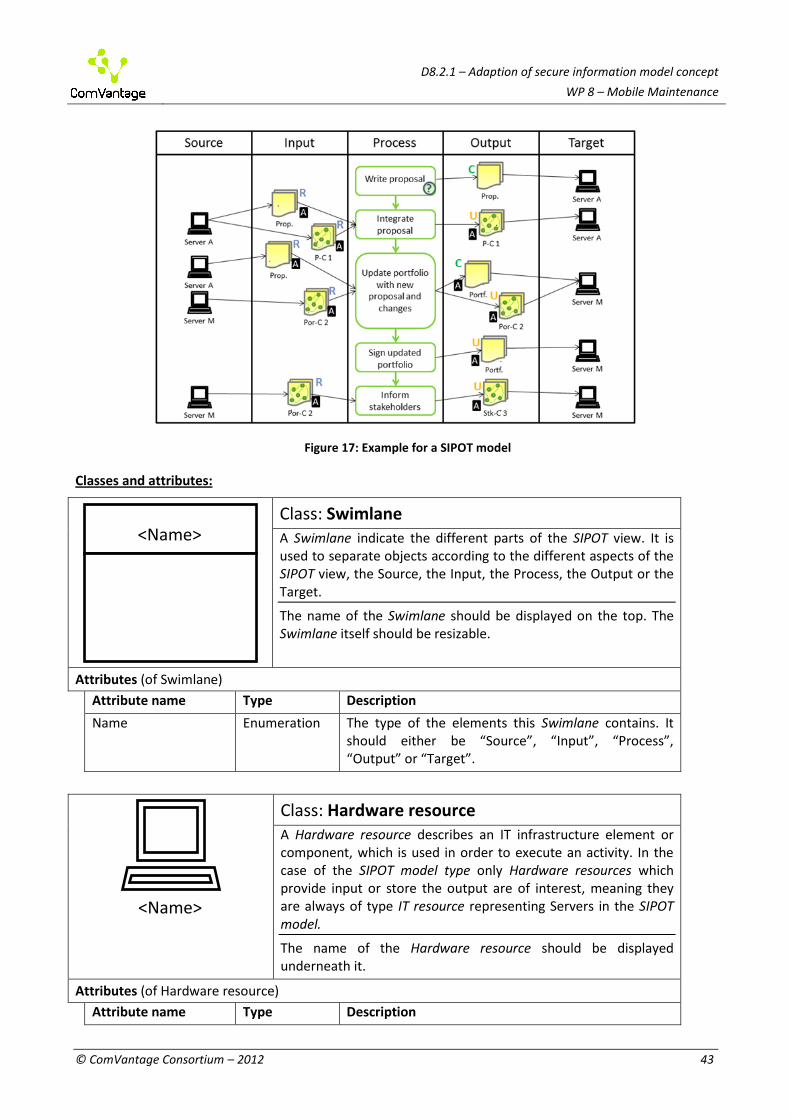
D8.2.1 – Adaption of secure information model concept
WP 8 – Mobile Maintenance
© ComVantage Consortium – 2012 43
Figure 17: Example for a SIPOT model
Classes and attributes:
Class: Swimlane A Swimlane indicate the different parts of the SIPOT view. It is used to separate objects according to the different aspects of the SIPOT view, the Source, the Input, the Process, the Output or the Target.
The name of the Swimlane should be displayed on the top. The Swimlane itself should be resizable.
Attributes (of Swimlane)
Attribute name Type Description
Name Enumeration The type of the elements this Swimlane contains. It should either be “Source”, “Input”, “Process”, “Output” or “Target”.
Class: Hardware resource A Hardware resource describes an IT infrastructure element or component, which is used in order to execute an activity. In the case of the SIPOT model type only Hardware resources which provide input or store the output are of interest, meaning they are always of type IT resource representing Servers in the SIPOT model.
The name of the Hardware resource should be displayed underneath it.
Attributes (of Hardware resource)
Attribute name Type Description
<Name>
<Name>

D8.2.1 – Adaption of secure information model concept
WP 8 – Mobile Maintenance
© ComVantage Consortium – 2012 44
Name String The name attribute describes the assigned name of the resource.
Description String A description of the Hardware resource for documentation purpose.
Roles and permissions Table The roles and permissions specify which roles have access to the resource and based on their permission which operation can be executed by the role.
Physical Digital
Linked Data Peripheral
Class: Information resource An Information resource represents a source of information which supports the execution of an Activity or Decision or can be the result of them. Documents, either physical or digital as well as Linked Data or peripherals providing input are Information resources. They represent design documents, task descriptions or orders and can either be unstructured or highly structured.
The name of the Information resource should be displayed underneath it. The notation should also change depending on the selected type. Furthermore, a letter at the top right should indicate if the resource is used as input (a blue “i”) or output (a green “o”) based on the Works on information relation.
Attributes (of Information resource)
Attribute name Type Description
Name String The name attribute describes the assigned name of the information resources.
Type Enumeration The type or channel through which the information is received. Can either be a) physical, b) synchronous digital, c) asynchronous digital, d) Linked Data or e) peripheral. Physical information resources are physical documents. Digital information resources can be either synchronous (i.e. manipulated on demand/on the fly) or asynchronous (e.g. email). Linked Data information resources are a special form of synchronous information resources. Peripheral information resources for information sent to be displayed on devices.
Description String Describes the information resource usage and is used for documentation purpose.
Roles and permissions Table The roles and permissions specify which roles have access to the resource and based on their permission which operation can be executed by the role. Therefore it contains one column for the role and one for the permissions.
Referenced data String The referenced data allows referencing real data either from the file system or through a URI of the

D8.2.1 – Adaption of secure information model concept
WP 8 – Mobile Maintenance
© ComVantage Consortium – 2012 45
provider and assigning it to the Information resource. The tool should allow retrieving and showing the data in a browser using the Parameter-value list or Query attribute.
Parameter-value list Table This attribute can be used to specify parameters and their values in case the Referenced data is an URI and the data can be accessed by parameterising it. The table should have two columns to specify the parameter name and what value it should have.
Query String This attribute can be used to specify a query which executed on the specified Referenced data attribute results in the actual data represented by this Information resource.
Class: Step A step represents some action or activity which has to be performed to achieve the goal of a process and which granularity is detailed enough to be of use for describing the Information resource exchange. It is connected to an Activity, indicating what it is a part of.
The name of the Step should be displayed inside of it. Furthermore, the colour should depend on the type, using the light green stroke for manual steps and a light blue stroke for automated steps. If the decision table contains any rows then the small icon with the question mark should be visible, otherwise it should be hidden.
Attributes (of Step)
Attribute name Type Description
Name String The name attribute indicates what is done during this step.
Type Enumeration Indicates how the Step is performed, either a) Manual or b) Automated (as in the case of IT Systems or Scripts).
Description String Further describes the Step and is used for documentation purpose.
Decisions Table The decisions table describes what decisions have to be made during or right after the step which influence the process path. The table should store the “Question” from the Decision element (from the Process) as well as the “Transition condition” from the Sequence relation used on this path.
Relation Class: Leads to

D8.2.1 – Adaption of secure information model concept
WP 8 – Mobile Maintenance
© ComVantage Consortium – 2012 46
The Leads to relation puts the Steps into a sequence, indicating what Step leads to the next one.
If the Leads to relation passes over a Step then it should be drawn on top of it and be dashed.
FROM: Step
TO: Step
Cardinality: Many to many
Relation Class: Resource relation The Resource relation (in the context of a SIPOT model) connects a Step and an Information resource which is used or manipulated during this Step. It indicates what Information resources are used as input and output of a Step.
The General operation type specified in this relation should be indicated next to the Information Resource by using the first letter (C, R, U or D). It is also recommended to use different colours for each of the possible operations (C – Green, R – Blue, U – Orange and D – Red). Also if the Resource relation is the endpoint of a Supported by app relation this should be indicated by the small icon containing the A. This icon should be next to the Information Resource as well.
FROM: Step; Information resource
TO: Step; Information resource
Cardinality: Many to many
Attributes (of Resource relation)
Attribute name Type Description
Description String This attribute describes the name of the Resource relation and is used in order to show in which context a resource is used.
General operation type
Enumeration Indicates the general operation executed on the connected Information resource. Must be one of: a) Create, b) Read, c) Update or d) Delete.
Operation String States what operation is executed on the resource.
Cost Number States the cost for using the connected resource in the Step and therefore also in the Activity connected to this Step. This value should not be contained in cost of the corresponding Activity itself. The purpose of the separation is to differentiate the costs for using different resources (different equipment etc.).
Relation Class: On device The On device relation indicates from what Hardware resource

D8.2.1 – Adaption of secure information model concept
WP 8 – Mobile Maintenance
© ComVantage Consortium – 2012 47
the input data is taken from or on what Hardware resource the output data is stored.
FROM: Hardware resource; Information resource
TO: Hardware resource; Information resource
Cardinality: Many to many
No Notation Relation Class: Supported by app The Supported by app relation defines what uses of data (performing an operation on an Information resource) in a Step should be supported by a Mobile support feature.
FROM: Resource relation
TO: Mobile support feature
Cardinality: Many to many
No Notation Relation Class: Part of activity The Part of activity relation indicates what Steps are parts of which Activity. It allows linking several Steps to one Activity and therefore to further decompose an Activity if it is necessary for the SIPOT model.
FROM: Step
TO: Activity
Cardinality: Many to 1
Constraints
1. Each different Swimlane type must be used exactly once and in the following order: Source, Input, Process, Output and Target.
2. Hardware resources are found only in Swimlanes of the type “Source” or “Target”. 3. Information resources are found only in Swimlanes of the type the “Input” or “Output”. 4. Steps are found only in the Swimlane of the type “Process”. 5. Each Step must be linked to one Activity from a Process model. The same Activity can be used for
several Steps. This allows decomposing an Activity in a SIPOT model into several Steps. 6. The Resource relation must connect exactly one Step and one Information resource. In case the
Information resource is in an “Input” type Swimlane the source of the Resource relation must be the Information resource. Otherwise, the source of the Resource relation must be a Step.
7. The On device relation must connect exactly one Information resource and one Hardware resource. In case the Hardware resource is in a “Source” type Swimlane the source of the On device relation must be the Hardware resource. Otherwise, the source of the On device relation must be an Information resource.

D8.2.1 – Adaption of secure information model concept
WP 8 – Mobile Maintenance
© ComVantage Consortium – 2012 48
Mechanisms/Algorithms
1. Synchronisation between the Information resources and Mobile support features assigned to the Steps/Resource relation and the corresponding Activities in the Process model should be performed automatically.
a. Assigning an Information resource to a Step in the SIPOT model should automatically also connect the same Information resource to the Activity linked through the Part of activity relation.
b. Removing an Information resource from a Step should also remove it from the Activity if no other Step linked to the same Activity makes use of the Information resource.
c. Removing an Information resource from an Activity in the Process model should also remove those Information resources from the linked Steps in the SIPOT model.
d. Adding a new Information resource should either add it automatically to the Step (if only one Step is linked to the Activity through Part of activity relation in one SIPOT model) or notify the user that he has to add it to the SIPOT model (if several Steps are linked to the Activity through the Part of activity relation in one SIPOT model).
e. The same should happen with Mobile support features assigned to Steps via the Resource relation.

D8.2.1 – Adaption of secure information model concept
WP 8 – Mobile Maintenance
© ComVantage Consortium – 2012 49
3 THE SECURITY FRAMEWORK ADAPTATIONS The following section 3.1 presents the defined access control model, which has already been specified in D3.2.1. Section 3.2 presents other required components that are needed to guarantee the global security but are not part of the defined access control model. Finally, section 3.3 presents some information that has been gathered in order to adapt the defined access control framework to the concrete needs of WP8.
3.1 The Multi-tiered Access Control Architecture
The access control architecture included into the global approach has been designed as a multi-tiered approach; specifically it is composed by two layers. The first tier is situated inside the web layer of the Domain Access Server and it is based on the filtering of the SPARQL queries. The second tier is situated inside the Domain Source Layer and it is based on the use of multiple endpoints.
Figure 18: Multi-tiered access control architecture

D8.2.1 – Adaption of secure information model concept
WP 8 – Mobile Maintenance
© ComVantage Consortium – 2012 50
The access control model also includes other modules that are common, the Traceability Manager, the Policy Admin and the LD Information Manager. In Figure 18, which is a simplified version of the ComVantage global architecture, it is possible to observe all the modules of the access control model. They are highlighted in colours.
The filtering module (in green) is composed of the Filtering AC Authentication and the Filtering Access Control. The Filtering Access Control analyses each SPARQL query received to give a permit or deny response, focusing on the predicates that are in the query, their role and taking into account the role of the application that is performing the query, making use of the Domain Policies stored in the Domain Configuration Layer. To ensure that the application has the permission to perform queries, the module contains an authentication component (Filtering AC Authentication) responsible of the task.
The multiple endpoints module (in violet) implies the publishing of Linked Data into different SPARQL endpoints taking into account the ComVantage roles defined. To ensure that each SPARQL endpoint is protected against unauthorised access, the module deploys an authentication mechanism in front of the endpoints.
The policy admin (in red) is the tool required to administrate the domain policies. The LD information Access Manager (in red) is responsible of showing the user all the resources that are accessible to the user’s role. It is also responsible of managing the exceptional and temporary access requests.
The traceability managers (in orange) are responsible of storing all the relevant information of each access control request in the access logs.
3.2 Other Required Components
There are other components shown in the previous figure that are not part of the Linked Data access control model, however they are required to ensure the global security. Those components are the different authorisation mechanisms of the two general types of applications, internal or external applications. An internal application is an application designed to be used by ComVantage authorised users, and a ComVantage authorised user is a member of the staff of a ComVantage company. On the contrary, an external application is an application designed to be used by a non ComVantage user, ex. a client of the online shop. Furthermore, each application should take into account the user connected to enable the access only to the predefined information and/or functionalities.
3.3 Adaptation of the Security Model to the WP8 Application Area
Once the generic security model has been defined, it must be adapted to the needs of each application area. That is, taking into account the security model defined, some adaptations must be performed in order to customise it.
In order to know to which extent the security model has to be adapted and which parts of the security model can be common to all application areas, it is important to know some information regarding the existing infrastructures and the security mechanisms that are aimed to be developed in each case.
In order to obtain this information from all partners in the application area, a questionnaire has been sent to each of them. The following table (Table 1) shows the questions and answers that have been collected regarding security aspects for WP8:
ID Question Answers
1 Are the applications centralised or distributed?
The user app, (called SupportAPP) is running on the mobile device of each user, so it is distributed.
2 Do you have any user directory for the prototype implementation?
At the moment we do not have any user directory.
3 Are you taking into account We will definitely have a role based access limitation

D8.2.1 – Adaption of secure information model concept
WP 8 – Mobile Maintenance
© ComVantage Consortium – 2012 51
ID Question Answers
functionality security restrictions for each role that uses the application?
mechanism. We will still have to specify, where the AccessControl Instance of the Domain Access Server gets its AccessLimitations from.
4 Have you decided which authorisation mechanism are you going to deploy to on the applications?
No, we rely on the WP3 recommendations
Table 1: Security questionnaire
Taking into account the answers received some conclusions can be stated, which will serve as an input for the adaptation of the security model to the needs of the partners in the WP8 application area.
First of all, the applications will be distributed, that is, each user device runs a ComVantage application that needs access to the Domain Access Server. Therefore, as the applications will not be centralised, it will not be possible to restrict the connections from certain IPs (those of the centralised applications).
Second, as no user repository exists currently, it is necessary to deploy one for the prototype. Third, this point is emphasised because the application will connect to the Domain Access Server
with its own role/credentials, not with the role/credentials of the user. Depending of the role of each user, the application should perform parameterised SPARQL queries that ComVantage Access Control component will filter/permit/deny depending of the role of the application.
Finally, this question was made in order to ensure that all security chain is enough secure. In order to develop a proper security prototype adapted as much as possible to the needs of each application area, some other questions have been posed to the partners of the application area. These questions and the gathered answers are exposed in Table 2:
ID Question Answers
5 Which data do you want to store in Linked Data?
•Live data of sensors •Machine`s semantic; the components of the machine. •Visualisation semantic: the format in which data will be visualised •Test semantic: history test results •History Data (earlier stored Sensor and Actuator Data)
6 In which format do you want to store the information stated above?
•Live data of sensors --> RDF format (Linked Data) via http GET method •Machine`s semantic --> dhm: ontology (data harmonisation middleware) •Visualisation semantic --> list, table, etc. •Test semantic --> ds: ontology (dataseries)
7 Which ComVantage roles do you want to define?
• CV_SvTn (Service_Technician) • CV_MMCO (Mobile Maintenace Coordinator) • CV_ME (Machine Expert) • CV_Customer - Factory Owner or one of his employees • CV_Producer - Producer of the Active Machine • CV_PAMMS - Predictive Active Machine Maintenance Support • CV_EPAMMS – Extended Predictive Active Machine Maintenance Support
Table 2: Security questionnaire for prototype implementation

D8.2.1 – Adaption of secure information model concept
WP 8 – Mobile Maintenance
© ComVantage Consortium – 2012 52
By means of this information, regarding the data that will be published in Linked Data and the kinds of roles that will have access to this data, a security prototype adapted to each application area needs will be developed in a more accurate way.
4 CONCLUSION AND OUTLOOK
4.1 Conclusions
This document describes adaptations of the generic concepts provided in deliverables of work package 3, on its two main subtasks:
modelling method adaptations; security framework adaptations.
Regarding the modelling method, the Mobile Maintenance application area scenarios suggested the following set of extensions to the generic ComVantage modelling method:
Support for defect design modelling mapped on maintenance and testing processes. This was approached by designing a model type that can express both preventive defect models and actual machine states (which can be stored in a defect models repository or compared against one to identify a close match which can suggest the maintenance process);
Support for expressing skills for experts involved in maintenance; the skills can be split in two categories: required and available, then matched against each other to discover performers that are able to fulfil a role;
Support for expressing service level agreements in a structured way, which opens possibilities for some level of automation in designing or matching the quantitative components of an SLA (price, validity, quantitative goals) against potential run-time data;
Support for designing the mobile support models in terms of requirements, for supporting a certain process rather than a way of indicating concrete UI elements. The UI elements view will be kept to emulate apps for the process stepper functionality, on the assumption that existing concrete apps have already been attached to process elements;
Support for detailed mapping of a process path on the data requirements of each process step, emphasising the need for Linked Data consumption.
Regarding the security framework, a common model has been provided which can accommodate the 3 different application areas. This security model adaptation will need to be instantiated based on the information assets individualised by each application area. The adaptation reveals that some common security mechanisms can be implemented over the 3 application areas (the ComVantage security concept). However, such access control component should be supported by individual systems and mechanisms that need to be implemented by each domain that rely on more traditional technology. In combination with the ComVantage security concept, such mechanisms are sufficient to leverage secure multi-domain collaboration.
4.2 Outlook and Open Issues
The next iteration of the deliverable (D8.2.2) will have to consider the following open issues:
SLA influences by geography and vice versa: SLA quantitative terms (responsive time) can be constrained by logistical restrictions and routing can be constrained by SLA obligations;
Further refinement regarding the app model comparison and mapping between Abstract and Concrete UI is necessary;
Validation of the modelling method will be initiated as the modelling tool will become available; A more detailed adaptation of the access control framework taking into account the peculiarities
and needs of WP8.

D8.2.1 – Adaption of secure information model concept
WP 8 – Mobile Maintenance
© ComVantage Consortium – 2012 53
5 REFERENCES Bicheno, J. and Holweg, M. (2009) The Lean Toolbox, PICSIE Books.
Dreyfus, S. E. and Dreyfus, H. L. (1980) ‘A Five-Stage Model of the Mental Activities Involved in Directed Skill Acquisition’, Air Force Office of Scientific Research under contract F49620-79-C-0063. Berkeley: University of California; 1980.
Karagiannis, D. and Kühn, H. (2002) 'Metamodelling Platforms', in Bauknecht, K., Min Tjoa, A., Quirchmayer, G. (Eds.): Proceedings of the Third International Conference EC-Web 2002 – Dexa 2002, LNCS 2455, Springer, Berlin/Heidelberg, pp.451-464.
Márquez, A. C. (2010) The Maintenance Management Framework, Springer.

D8.2.1 – Adaption of secure information model concept
WP 8 – Mobile Maintenance
© ComVantage Consortium – 2012 54
DISCLAIMER
The information in this document is provided "as is", and no guarantee or warranty is given that the information is fit for any particular purpose. The above referenced consortium members shall have no liability for damages of any kind including without limitation direct, special, indirect, or consequential damages that may result from the use of these materials subject to any liability which is mandatory due to applicable law.
Copyright 2012 by SAP AG, Asociación de Empresas Tecnológicas Innovalia, Ben-Gurion University of the Negev, BOC Business Objectives Consulting S.L.U, Comau S.p.A., Dresden University of Technology, Dresscode 21 GmbH, Evidian S.A., ISN Innovation Service Network d.o.o., Kölsch & Altmann GmbH, Nextel S.A., RST Industrie Automation GmbH, University of Vienna.