Cold Heads, Two Stage - ColdEdge Technologiescoldedgetech.com/uploads/files/257519A DE-202 DE-204...
46
Cold Heads Displex ™ models DE-202, DE-204SL, DE-204SL-N, DE-208R and DE-208L Operating Manual Sumitomo (SHI) Cryogenics of America, Inc. 1833 Vultee Street Allentown, PA 18103-4783 U.S.A. Revision I: June 2007 257519A
Transcript of Cold Heads, Two Stage - ColdEdge Technologiescoldedgetech.com/uploads/files/257519A DE-202 DE-204...

Cold Heads
Displex™ models DE-202, DE-204SL, DE-204SL-N, DE-208R and DE-208L
Operating Manual
Sumitomo (SHI) Cryogenics of America, Inc. 1833 Vultee Street
Allentown, PA 18103-4783 U.S.A.
Revision I: June 2007 257519A


TABLE OF CONTENTS
Page
SAFETY ........................................................................................................................ 1
SERVICE ........................................................................................................................ 5
INTRODUCTION ............................................................................................................ 7
PRINCIPLES OF OPERATION ...................................................................................... 9
COMPONENTS ............................................................................................................ 13 Valve Motor Assembly ...................................................................................... 14 Valve Disc ......................................................................................................... 15 Valve Stem ........................................................................................................ 15 Cylinder Assembly ............................................................................................ 16 Displacer Assembly ........................................................................................... 16 Displacer Seals ................................................................................................. 17
SPECIFICATIONS ........................................................................................................ 19 Refrigeration Capacities, Cooldown Times, Weights (Typical) ......................... 19 DE-204SL-N Cold Heads .................................................................................... 19 Pressure Relief Valve ........................................................................................ 19 Electrical Characteristics ................................................................................... 20 Mounting Position .............................................................................................. 20 Insulating Vacuum (non-MRI applications) ........................................................ 20 Color Codes ...................................................................................................... 20 Refrigerant Quality ............................................................................................ 20 Supplier Name and Address ............................................................................. 20 Dimensions ....................................................................................................... 21
INSTALLATION ............................................................................................................ 25 Inspection .......................................................................................................... 25 Mounting ........................................................................................................... 25 Interconnections ................................................................................................ 25 Gas Lines .................................................................................................... 25 Cold Head Cable and Instrument Leads ..................................................... 26 Evacuate Shroud (non-MRI applications) ......................................................... 26
OPERATION ............................................................................................................... 29 Startup ............................................................................................................... 29 Cold Head Orifice Adjustment (Models DE-208R and DE-208L only) ............... 29 Vacuum Bake the Cold Head ............................................................................ 30 Vacuum Bake the Cylinder ................................................................................ 30 TROUBLESHOOTING ................................................................................................. 33 Troubleshooting Guide........................................................................................ 33 Electrical Checks................................................................................................. 35 Valve Motor Checks ........................................................................................... 35 Valve Motor Fuse, Resistor and Capacitor Checks .......................................... 36
i

TABLE OF CONTENTS (Continued)
Page ILLUSTRATIONS LIST Figure 1 Simplified Cold Head Diagram .......................................................... 9 Figure 2 Cold Head Intake, Valve Open, Displacer Down ............................. 10 Figure 3 Cold Head Valve Closed, Displacer Moving Up .............................. 10 Figure 4 Cold Head Exhaust, Valve Open, Displacer Up .............................. 11 Figure 5 Cold Head Valve Closed, Displacer Moving Down .......................... 11 Figure 6 Typical Cold Head Assembly .......................................................... 13 Figure 7 Valve Motor Assembly .................................................................... 14 Figure 8 Valve Disc and Valve Stem ............................................................. 15 Figure 9 Displacer Assembly ......................................................................... 16 Figure 10 DE-202 Cold Head Outline Dimensions .......................................... 21 Figure 11 DE-204SL and DE-204SL-N Cold Head Outline Dimensions ........... 22 Figure 12 DE-208R and DE-208L Cold Head Outline Dimensions ................... 23 Figure 13 Connect Aeroquip Coupling ............................................................ 26 Figure 14 Measure Motor Winding Resistance ................................................. 36 Figure 15 Check Ground Connection................................................................ 36 Figure 16 Check Valve Motor Resistor ............................................................ 37 Figure 17 Check Valve Motor Capacitor ......................................................... 38 Figure 18 Check Valve Motor Capacitor ......................................................... 38 Figure 19 Valve Motor Electrical Schematics .................................................. 39
ii

(This page is intentionally blank.)
iii

(This page is intentionally blank.)
iv
SAFETY
GENERAL
SCAI equipment is designed to operate safely when the installation, operation and servicing are performed in accordance with the instructions in this technical manual. Consult the nearest SCAI Service Center with any questions you may have concerning the use or maintenance of this equipment. For Service Center locations, see the Service section in this manual.
SPECIAL NOTICES Three types of special notices -- WARNINGS, CAUTIONS and NOTES are used in this technical manual.
WARNINGS call attention to actions or conditions that can result in injury or death.
CAUTIONS call attention to actions or conditions that can result in damage to the equipment or in abnormal performance.
NOTE NOTES give important, additional information, explanations or recommendations related to the appropriate topic or procedure. WARNINGS and CAUTIONS, like other safety instructions, appear within rectangles in the text where they are applicable. Because of their importance, they are summarized in this Safety section, and should be read first.
NOTE Parallel lines (||) in the right margins identify changes from the previous revision.
1

Safety
WARNINGS
HIGH PRESSURE GAS HAZARDS Never use compressed helium gas from a cylinder without a proper regulator. Overpressure can cause serious injury if the system equipment ruptures. Always wear eye protection when handling pressurized gas lines and other pressurized equipment. Never apply heat to a pressurized gas line or other pressurized components. Disconnect gas lines only when the compressor is stopped. Disconnecting the cold head while it is cold can create excessively high internal pressure as the gas warms. Material failure and uncontrolled pressure release can cause serious injury. Use two wrenches when disconnecting a gas line coupling to avoid loosening the shield cooler coupling. Gas pressure can project the coupling with enough force to cause serious injury. The cold head is charged with helium gas. Vent both supply and return Aeroquip couplings to atmospheric pressure before disassembly, except when disconnecting gas lines. Uncontrolled pressure release can cause serious injury. Always vent a gas-charged component before beginning to disassemble its couplings. Gas pressure can launch a loose coupling with enough force to cause serious injury. When relieving the vacuum with dry air or nitrogen, backfill only to atmospheric pressure (zero psig). The vacuum shroud is not a pressure vessel. Serious injury and equipment damage can result. HIGH VOLTAGE HAZARDS All electrical supply equipment must meet applicable codes and be installed by qualified personnel. Disconnect the power to the compressor before troubleshooting the electrical components. Permit only qualified electrical technicians to open electrical enclosures, to perform electrical checks or to perform tests with the power supply connected and wiring exposed. Failure to observe this warning can result in serious injury or death. AVOID INJURY FROM BURNS. During operation, some surfaces under the compressor’s cover become hot. Allow the compressor to cool for 1/2 hour after shutdown before removing the cover for maintenance.
2

Safety
CAUTIONS
PRESERVE YOUR WARRANTY. Modification to equipment without the consent of the manufacturer will void the warranty. Specifications require the use of 99.995% pure helium gas. Using a lesser quality of helium can damage the system and void the warranty. AVOID GAS LEAKS. Check the condition of the gasket seal on the male half of each Aeroquip coupling. Be sure the gasket seal is in place and the sealing surfaces on both the male and female halves are clean before connecting. Replace the gasket seal if it is damaged or missing. Keep the gas line couplings aligned when making or breaking a coupling connection. Leaks can occur due to the weight of the gas line or due to a sharp bend near the connection. PREVENT EQUIPMENT DAMAGE. Damage to gas lines can result from crimping by repeated bending and repositioning. Do not heat cold head assemblies above 80º C (176º F). Do not heat cold head cylinders with instrumentation removed above 150º C (300º F). The cold head’s orifice has been factory set for optimal performance at customer’s stated electrical frequency. This frequency, either 50 or 60 Hz is identified by the label on the cold head’s motor housing. Check that the labeled frequency agrees with customer’s frequency. Operating an cold head labeled “Factory set for 50 Hz operation” on 60 Hz electrical service may damage the displacer. The orifice in a cold head labeled “Factory set for 50/60 Hz operation” needs no adjustment. AVOID A MALFUNCTION. Repeatedly charging the system with helium gas rather than locating and repairing gas leaks can cause a malfunction. Impurities are introduced at an abnormal rate and can freeze in the shield cooler. Do not allow air to get into the helium gas refrigerant of the system. Moisture from the atmosphere can seriously degrade cold head performance. Do not install a valve disc whose critical surface is dirty or blemished. Avoid damaging the critical surfaces of the valve stem and the valve disc. Degraded operation can result. The O-rings used on the displacer are made of special material. Do not substitute standard O-rings. Do not apply a lubricant to any displacer O-rings, seal rings or seal grooves. Avoid trapping contaminants inside the cold head. Do not assemble parts that are in questionable condition. Never open the vacuum valve when the connected vacuum pump is not running. The cold cold head can cryopump oil into the shroud (non-MRI applications.) AVOID CONTAMINATION. Follow the charging or venting procedures to prevent reversed flow of system gas. Do not charge through the supply coupling. Do not vent through the return coupling. Reversed flow can contaminate the system with compressor oil.
3

(This page is intentionally blank.)
4
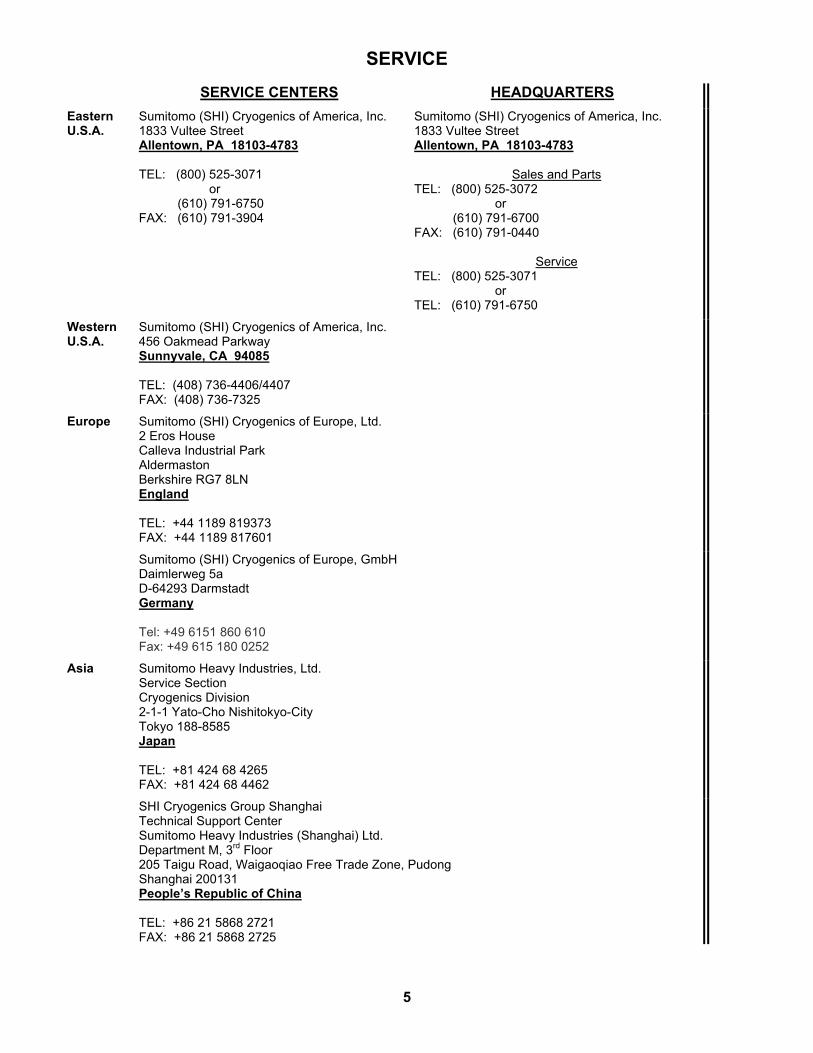
SERVICE
SERVICE CENTERS HEADQUARTERS
Eastern U.S.A.
Sumitomo (SHI) Cryogenics of America, Inc. 1833 Vultee Street Allentown, PA 18103-4783 TEL: (800) 525-3071 or (610) 791-6750 FAX: (610) 791-3904
Sumitomo (SHI) Cryogenics of America, Inc. 1833 Vultee Street Allentown, PA 18103-4783
Sales and Parts TEL: (800) 525-3072 or (610) 791-6700 FAX: (610) 791-0440
Service TEL: (800) 525-3071 or TEL: (610) 791-6750
Western U.S.A.
Sumitomo (SHI) Cryogenics of America, Inc. 456 Oakmead Parkway Sunnyvale, CA 94085 TEL: (408) 736-4406/4407 FAX: (408) 736-7325
Europe Sumitomo (SHI) Cryogenics of Europe, Ltd. 2 Eros House Calleva Industrial Park Aldermaston Berkshire RG7 8LN England TEL: +44 1189 819373 FAX: +44 1189 817601
Sumitomo (SHI) Cryogenics of Europe, GmbH Daimlerweg 5a D-64293 Darmstadt Germany Tel: +49 6151 860 610 Fax: +49 615 180 0252
Asia Sumitomo Heavy Industries, Ltd. Service Section Cryogenics Division 2-1-1 Yato-Cho Nishitokyo-City Tokyo 188-8585 Japan TEL: +81 424 68 4265 FAX: +81 424 68 4462
SHI Cryogenics Group Shanghai Technical Support Center Sumitomo Heavy Industries (Shanghai) Ltd. Department M, 3rd Floor 205 Taigu Road, Waigaoqiao Free Trade Zone, Pudong Shanghai 200131 People’s Republic of China TEL: +86 21 5868 2721 FAX: +86 21 5868 2725
5

(This page is intentionally blank.)
6

INTRODUCTION
All the cold heads (expanders) described in this manual are two-stage cryogenic refrigerators that operate on the Gifford-McMahon refrigeration cycle. Each uses helium gas from a helium compressor(s) to produce the cold temperatures. Electricity to power the cold head’s valve motor is supplied from the compressor by the cold head cable. To be functional, the cold head is fitted with other parts or equipment so it can remove heat from the connected interfaces. Applications include laboratory systems for test sample cooling, cryopumps for clean, high-vacuum service and shield coolers and recondensers for cryogenic conservation, as in magnetic resonance imaging (MRI) medical diagnostic instruments. The typical, complete operating system, using SCAI standard components, consists of a helium compressor(s), interconnecting gas lines, the cold head with its interface attachments, and optional instrumentation. Pressures are stated as gauge, not absolute. Psig is pounds per square inch gauge and kPa is Kilopascals gauge, kPa = 6.895 x psig.
7

(This page is intentionally blank.)
8

PRINCIPLES OF OPERATION
The major parts of the Displex™ Cold Head are shown in Figure 1. Figures 2, 3, 4 and 5 illustrate the valve and displacer movements, and the directions of gas flow. The valve motor drives the rotating valve disc that controls the flow of the helium gas. The high-pressure helium gas drives the reciprocating displacer assembly within the cylinder assembly. Ports in the valve disc allow two complete cycles of the displacer for every revolution of the valve disc.
Figure 1 Simplified Cold Head Diagram
9

Principles of Operation
As shown in Figure 2, high-pressure helium admitted by the rotating valve disc flows through passages in the slack cap and enters the regenerators. The regenerators, cooled during the previous exhaust stroke, cool the incoming gas as it flows through. Gas flowing through the slack cap passages raises the cap to engage and lift the displacer, creating expansion space at the heat stations for gas that has passed through the regenerators. See Figure 3. Also, as the displacer lifts, gas above the slack cap is partially compressed and pushed through the orifice into the surge volume. Before the displacer reaches the valve stem, the valve closes. Compression of gas above the slack cap decelerates and stops the displacer before it can collide with the valve stem.
Figure 2 Cold Head Intake, Valve Figure 3 Cold Head Valve Closed, Open, Displacer Down Displacer Moving Up
10

Principles of Operation
Figure 4 shows the exhaust stroke. When the valve opens to exhaust, high-pressure gas at the heat stations is free to expand and refrigerate them. The exhausting gas also cools the regenerators. As the pressure drops, partially compressed gas bleeds from the surge volume, pushes the slack cap and displacer toward the heat stations, forces exhaust, and positions the displacer for the next cycle. The valve closes again, and residual gas acts as a cushion to decelerate and stop the displacer before it collides with the heat stations. See Figure 5. Heat station temperature is progressively reduced to provide refrigeration at cryogenic temperatures.
Figure 4 Cold Head Exhaust, Valve Figure 5 Cold Head Valve Closed Open, Displacer Up Displacer Moving Down
11

(This page is intentionally blank.)
12

COMPONENTS
Figure 6 shows an external view of a typical cold head.
Valve Motor Housing
Variable Orifice Valve (Models DE-208R, DE-208L only)
Valve Motor Base
Warm Flange
Cold Head Cable Electrical Receptacle
Fusible Plug
Gas Return Coupling
Gas Supply Coupling
Second Stage Heat Station
First Stage Heat Station
Figure 6 Typical Cold Head Assembly
13

Components
Valve Motor Assembly The valve motor assembly, Figure 7, includes the motor housing, valve motor and motor base. The motor housing includes the cold head cable electrical receptacle, the fusible plug and the gas supply (red) coupling. The motor base includes the gas return (green) coupling.
Cold Head Cable Electrical Receptacle
Fusible Plug
Gas Supply Coupling
Gas Return Coupling
Valve Motor Shaft
Valve Motor Base
Valve Motor
Valve Motor Housing
Figure 7 Valve Motor Assembly The valve motor fastens to the motor base, which fastens to the motor housing. There is an O-ring seal between the base and the housing. The motor shaft extends through a hole in the base and is fitted with roll pins and a compression spring which form a coupling for the valve disc. The only purpose of the motor is to turn the valve disc. Bolts passing through the housing and base fasten the valve motor assembly to the warm flange of the cylinder assembly. A fusible plug is located between the electrical receptacle and the gas supply coupling. The fusible element will melt and vent the gas charge to avoid the pressure increase that could occur if the cold head were exposed to a fire.
14

Components
Valve Disc The valve disc, Figure 8, fits on the motor shaft and is held against the valve stem by the combination of a spring and gas pressure. Valve disc rotation and porting and valve stem porting combine to time and control the cold head’s working cycle by reversing the gas flow between periods of interrupted flow.
Figure 8 Valve Disc and Valve Stem
Valve Stem The valve stem, Figure 8, seats in the motor base. The valve disc rotates against the valve stem. The mating surface of the valve stem is specially treated to resist wear. Two O-rings provide sealing between the valve stem and the motor base. The stem includes a capillary and an orifice that control surge flow. These factory-installed items are not serviced in the field. The orifice is adjustable in cold head models DE-208R and DE-208L. See the Operation section. Cold head models DE-202, DE-204SL and DE-204SL-N have different orifices for 50 Hz and for 60 Hz. The valve stem shank is also specially treated to resist wear and acts as a slide for the slack cap and a guide for the displacer. The mating surfaces on both the stem and the disc must be protected when these components are not in the cold head. See the Maintenance section.
15

Components
Cylinder Assembly The cylinder assembly houses the displacer assembly. The cylinder assembly consists of:
Warm Flange - This is the main mounting base of the cold head. The valve motor assembly and the cylinder assembly are bolted to this flange. O-rings seal the mating faces. When used, the skirt is attached to the warm flange. Heat Stations - These are the areas of concentrated refrigeration, located at the ends of the first- and second-stage regenerators. For a cryopump application, first- and second-stage cryopanels fasten to the first- and second-stage heat stations respectively. For a laboratory application, typically a sample holder is mounted to the second-stage heat station and a radiant heat shield mounts to the first stage. Skirt - Instrumentation feedthroughs, vacuum pumpout port and vacuum shroud are fastened to the skirt. Some applications do not require a skirt. For others, the skirt configuration varies to suit the application.
Displacer Assembly The displacer assembly, housed within the cylinder assembly, includes the first- and second-stage displacers, the coupling between them, the slack cap and the seal rings. See Figure 9. The first- and second-stage displacers are held together by a pin-type coupling and can be separated if there is a need. The regenerators are inside the displacers and are not repaired, serviced or replaced. The slack cap is coupled to the first-stage displacer and is not removed from it. The seal rings are wear items and are replaceable. The displacer assembly must be protected from humidity whenever it is not in the cylinder assembly. Instructions are in the Maintenance section.
Figure 9 Displacer Assembly
16

Components
Displacer Seals The displacer has four sets of seal rings: One set on each of the outsides of the second stage, the first stage, the slack cap and one set on the inside of the slack cap. The second-stage seal rings are backed by a garter spring to maintain contact pressure. Pressure at the other three locations is maintained by special backing O-rings. The seal rings are made from carbon-filled Teflon and each is slit for easy installation and removal.
17

(This page is intentionally blank.)
18

SPECIFICATIONS
Refrigeration Capacities, Cooldown Times, Weights (Typical)
Cold Head Model
Hz First Stage Capacity
Watts @ 77K
Second Stage Capacity, Watts
@ 20K @ 10K
Cooldown Time to 20K
Minutes
Weights lbs kg
DE-202 60 8.8 2.2 65 15 6.8 50
7.3 1.8 75
DE-202 60 50
_ _
2.5 2.0
65 75
15 6.8
DE-204SL 60 16.2 @ 80K 8.1 30 17 7.7 50
13.5 @ 80K 6.7 35
DE-204SL 60 50
_ _
9.0 7.5
35 40
17 7.7
DE204SL-N 60 _ _ 3.0 35 17 7.7 50
_ _ 2.5 40
DE-208R 60 80 7.5 45 34 15.4 50
65 6.0 55
DE-208L 60 35 10.0 40 34 15.4 50 28 8.0 50
DE-204SL-N Cold Heads DE-204SL and DE-204SL-N Cold Heads are the same except for the second stage displacer. Pressure Relief Valve The cold head shall be connected to a gas supply source having a pressure relief valve set at 2760 kPa (400 psig) gauge maximum.
NOTE SCAI compressors are supplied with properly set pressure relief valves.
19

Specifications
Electrical Characteristics
For all cold head models: 208/230 (±5%) V∼, 60 Hz or 200 (±5%) V∼, 50 Hz. The cold head cable from the compressor supplies power for the valve motor. 0.63-ampere over-current protection shall be provided in the cold head power supply. A time-lag fuse shall be provided in each ungrounded supply conductor.
NOTE The appropriate over current protection is provided when SCAI Cold Heads are operated with SCAI compressors.
Mounting Position Functions normally in any position. Position is determined by customer’s application. Insulating Vacuum (non-MRI applications)
1 x 10⁻³ torr. See Evacuate Shroud in the Installation section. Color Codes Aeroquip self-sealing couplings on the cold head and on the gas lines are color coded to identify their function as follows: Red - Helium gas supply to the cold head from the compressor.
Green - Helium gas return from the cold head to the compressor. Refrigerant Quality
Refrigerant is 99.995% pure helium gas with a dew point less than -50° C (-58° F) at 2070 kPa (300 psig). However, cold heads used in 4 degree Kelvin systems require 99.999% pure helium gas. Supplier Name and Address Sumitomo (SHI) Cryogenics of America, Inc. 1833 Vultee Street Allentown, PA 18103-4783 U.S.A. (610) 791 - 6700.
20

Specifications
Dimensions Dimensions are in inches and (millimeters). See Figures 10, 11 and 12.
Figure 10 DE-202 Cold Head Outline Dimensions
21

Specifications
Figure 11 DE-204SL and DE-204SL-N Cold Head Outline Dimensions
22

Specifications
(Note: Dimensions not shown are the same as on DE-208R.)
Figure 12 DE-208R and DE-208L Cold Head Outline Dimensions
23

(This page is intentionally blank.)
24

INSTALLATION
Inspection Unpack the equipment and inspect it for damage. Cold heads are shipped fully charged with helium gas. After all system components have been connected, the equalization pressure indicated by the compressor gauge will determine if charging or venting of the system is required. Mounting Customer’s application determines the mounting position and method. The cold head will function in any position. Allow sufficient space for installing and removing the interfacing attachments, connecting the gas lines and the vacuum hose, and operating the vacuum valve. The references to vacuum components do not apply to an MRI installation. Interconnections Gas Lines
Tools required: Open-end wrenches, 1”, 1 1/8”, 1 3/16”.
AVOID INJURY. When handling pressurized gas lines and other pressurized equipment, always wear eye protection. Never apply heat to a pressurized gas line or other pressurized components.
AVOID GAS LEAKS. Check the condition of the gasket seal on the male half of each Aeroquip coupling. Be sure the gasket seal is in place and the sealing surfaces on both the male and female halves are clean before connecting. Replace the gasket seal if it is damaged or missing.
AVOID GAS LEAKS. Keep the gas line couplings aligned when making or breaking a coupling connection. Leaks can occur due to the weight of the gas line or due to a sharp bend near the connection.
NOTE Retain the threaded dust caps and plugs to re-cover the couplings when they are not in use. They protect the couplings from damage and prevent entry of contaminants.
1. Using two wrenches, connect one end of the cold head supply gas line to the supply (red)
coupling on the cold head. Tighten all Aeroquip couplings to 4.8 ± 0.7 kgf m (35 ± 5 ft. lbs.). See Figure 13.
Tighten each coupling before proceeding to the next one. .
25

Installation
2. Connect the other end of this gas line to the supply coupling on the compressor.
3. Connect one end of the cold head return gas line to the return (green) coupling on the Cold Head.
4. Connect the other end of this gas line to the return coupling on the compressor.
Figure 13 Connect Aeroquip Coupling
Cold Head Cable and Instrument Leads
1. Connect the cold head cable to the cold head electrical receptacle on the valve motor housing.
2. Connect the other end to the cold head receptacle on the compressor.
NOTE For some applications, the cold head cable from the compressor is connected to an outboard electrical box. The cold head cable(s) from the outboard electrical box then connect(s) to the cold head cable receptacle on the cold head(s).
3. Leads for electrical and instrumentation connections are factory installed and terminate at
the skirt connector or as leads extending from a feedthrough fitting on the skirt. Evacuate Shroud (non-MRI applications)
The insulating, vacuum shroud should be pumped down to about 1 x 10⁻³ torr. A two-stage, oil-sealed mechanical vacuum pump with an ultimate pressure capability in the 10-4 torr range is satisfactory but mechanical pumps begin to backstream oil when operated close to the molecular flow range. Backstreaming must be prevented to avoid contaminating the shroud by pumping to a pressure no lower than 1 x 10⁻³ torr. Cleaner types of vacuum pumps, such as liquid nitrogen cold-trapped diffusion pumps, turbo molecular pumps and cryopumps, allow pumping to lower pressures such as 10-6 torr. The lower pressures reduce the residual heat load on the refrigerator at the start of the cooldown. See the appropriate cryopump and laboratory interface technical manuals for vacuum pumping procedures.
26

Installation
When the cold head is used in MRI applications, the references to vacuum components do not apply.
AVOID A MALFUNCTION. Never open the vacuum valve when the connected vacuum pump is not running. The cold cold head can cryopump oil into the shroud (non-MRI applications).
27

(This page is intentionally blank.)
28

OPERATION
Startup Starting the compressor(s) starts the cold head’s valve motor. No operating procedures are performed at the cold head when it is used in cryopump and MRI applications. However, when the cold head is used in laboratory systems, the sample and the interface must be attached to it, but the procedures vary according to the interfaces used and are presented in a separate technical manual.
NOTE Breaking the insulating vacuum while the cold head is below room temperature will cause frosting of the outside vacuum vessel. It is preferable to break the vacuum with dry nitrogen or dry air. This prevents the accumulation of moisture in the vacuum space, facilitating faster, subsequent pumpdowns.
AVOID INJURY. When relieving the vacuum with dry air or dry nitrogen, backfill only to atmospheric pressure (zero psig). The vacuum shroud is not a pressure vessel. Serious injury and equipment damage can result.
AVOID INJURY Never use compressed helium gas from a cylinder without a proper regulator. Overpressure can cause serious injury if the system equipment ruptures.
NOTE
During cooldown, the cold head may be noisy. When the unit is cooled down, the noise level will decrease to normal. If this does not occur, refer to the procedure in Cold Head Orifice Adjustment that follows.
Cold Head Orifice Adjustment (Models DE-208R and DE-208L only)
PREVENT EQUIPMENT DAMAGE. The cold head’s orifice has been factory set for optimal performance at customer’s stated electrical frequency. This frequency, either 50 or 60 Hz, is identified by the label on the motor housing. Check that the labeled frequency agrees with customer’s frequency. Operating a cold head labeled “factory set for 50 Hz operation” on 60 Hz electrical service may damage the displacer. The orifice in a cold head labeled “factory set for 50/60 Hz operation” needs no adjustment.
The variable orifice has been set at the factory for maximum refrigeration capacity. The orifice is located in the edge of the valve motor base, near the return gas coupling.
29

Operation
In most systems tested, minimum temperature was achieved with the orifice about 8 turns open (out 8 turns from full in position) for 60 Hz. Because of manufacturing tolerances, not all systems behave identically. An experienced operator can develop a technique to adjust the displacer motion to achieve best system performance. a) Make only small orifice stem changes (1/4 turn maximum).
b) Wait about one minute after making a change to observe the effect. Because maximum refrigeration is produced when the full stroke length of the displacer is utilized, it is normal for a very light tapping to occur when the unit is adjusted for minimum temperature. The unit can be adjusted to reduce the tapping noise. However, this results in a slightly shorter displacer stroke that causes a decrease in refrigeration produced and therefore an increase in first- and second-stage operating temperatures. Other cold head models are equipped with fixed orifices and therefore are not adjustable. Vacuum Bake the Cold Head
PREVENT EQUIPMENT DAMAGE. Do not heat cold head assemblies above 80° C (176° F).
Vacuum Bake the Cylinder Before disassembling the cold head, disconnect it from the system.
1. Press the compressor’s power switch to stop the compressor and the cold head. 2. Allow the cold head’s second-stage heat station to warm to at least 280 K (5° C or 41° F).
3. Begin disassembling the cold head. See the procedures in the Maintenance section of this manual: Preliminary Procedures, Disconnecting Gas Lines, Venting, Remove the Valve Motor Assembly and Remove the Displacer Assembly. Remove all instrumentation components.
NOTE
Immediately after removal, store the displacer assembly in an airtight, heat-sealed, moisture-proof container. If this cannot be done, refer to the procedure Vacuum Bake the Displacer in the Maintenance section.
PREVENT EQUIPMENT DAMAGE. Do not heat cold head cylinders with instrumentation removed above 150° C (300° F).
4. Vacuum bake the cold head cylinder. Do not exceed a baking temperature of 150° C
(300° F).
30

Operation
5. Allow the assembly to cool in the vacuum. After vacuum baking and cooldown,
reassemble the cold head parts in reverse order. See Reassemble the Cold Head and the procedures that follow in the Maintenance section.
6. See Return to Service. Follow this procedure, including Gas Cleanup of the Cold Head. This completes the procedure for vacuum baking the cylinder.
31

(This page is intentionally blank.)
32
TROUBLESHOOTING
The Troubleshooting Guide that follows lists problems that can occur and suggests causes and corrective actions. Consult also the Troubleshooting section of the Technical Manual for the Compressor.
AVOID ELECTRIC SHOCK. Permit only qualified electrical technicians to open electrical enclosures, to perform electrical checks or to perform tests with the power supply connected and wiring exposed. Failure to observe this warning can result in serious injury or death.
PRESERVE YOUR WARRANTY. Modification to equipment without the consent of the manufacturer will void the warranty.
Troubleshooting Guide
Problem Possible Cause Corrective Action Valve motor does not start when the compressor starts.
Cold head cable is not connected.
Stop the compressor. Connect the cable.
Open circuit in the cold head cable.
Disconnect the cold head cable. Check each conductor for continuity. Replace the cable if necessary.
Defective valve motor. Use the Valve Motor Check procedure.
Blown fuse in the compressor’s electrical box.
See the Troubleshooting section in the Compressor Technical Manual.
Valve motor hums but does not start.
Defective capacitor or resistor.
Use the Valve Motor Capacitor and Resistor Check procedure.
Defective valve motor. Use the Valve Motor Check procedure.
Open circuit in the cold head cable.
Disconnect the cold head cable. Check each conductor for continuity. Replace the cable if necessary.
33

Troubleshooting
Problem Possible Cause Corrective Action
Valve motor runs but there is no cooldown.
No insulating vacuum. Check the vacuum system for operation and leaks.
Gas line couplings are not fully engaged.
Be sure that all Aeroquip couplings are fully engaged and torqued.
Gas lines are connected wrong.
Reconnect. See the Installation section.
Compressor output is inadequate.
Troubleshoot the compressor. See the Compressor Technical Manual.
Shroud is sweating or abnormally cold.
Loss of insulating vacuum. Check the vacuum system for operation and leaks.
Abnormally noisy operation after a sustained period of five to fifteen minutes.
Incorrect compressor pressures.
Troubleshoot the compressor. See the Compressor Technical Manual.
Contaminants in the gas. Perform Gas Cleanup and Recharging procedure on the cold head, compressor and the gas lines. Refer to the appropriate Technical Manuals. If the problem remains, consult a SCAI Service Center.
Mismatch of electric service frequency with the frequency on the label adjacent to the cold head’s electrical receptacle.
Consult a SCAI Service Center.
Intermittent operation. Compressor is cycling on and off.
Troubleshoot the compressor.
Temperature cycling. Contaminated gas is causing an Cold Head freezing-thawing cycle.
Perform Gas Cleanup and Recharging procedure on the cold head, compressor and the gas lines. Refer to the appropriate Technical Manuals. If the problem remains, consult a SCAI Service Center.
Sudden loss of refrigeration capacity.
Loss of insulating vacuum. Check the vacuum system for operation and leaks.
34
Troubleshooting
Problem Possible Cause Corrective Action
Sudden loss of refrigeration capacity. (continued)
Compressor malfunction. Troubleshoot the compressor. See the Compressor Technical Manual.
Defective valve motor, resistor or capacitor.
Perform all the electrical checks.
Slow loss of refrigeration capacity.
Small insulating vacuum leak.
Leak check and repair the vacuum system.
Worn seals in the Cold Head.
Use appropriate disassembly and Repair procedures. Leaking seals will be confirmed by a streaming pattern of black particles on the displacer near the seal rings.
Cold Head is leaking. Use the Leak Check and Leak Repair procedure.
Electrical Checks Electrical checks are performed with an ohmmeter and with power disconnected. Figure 19 shows the electrical schematic.
AVOID ELECTRIC SHOCK. Permit only qualified electrical technicians to open electrical enclosures, to perform electrical checks or to perform tests with the power supply connected and wiring exposed. Failure to observe this warning can result in serious injury or death.
Valve Motor Checks Use an ohmmeter to check the valve motor.
1. Stop the compressor.
2. Disconnect the power from the compressor.
3. Disconnect the cold head cable from the cold head.
4. Measure the resistance of the valve motor windings across the cold head electrical receptacle pins. See Figure 14.
35

Troubleshooting
Pins Cold Head Models
Resistance, ohms
DE-202, DE-204SL,
DE-204SL-N
DE-208R, DE-208L
A to B 2000 ± 10% 330 ± 10%
B to C 1000 ± 10% 165 ± 10%
A to C 1000 ± 10% 165 ± 10%
D to ground (on cold head housing)
0 0
If the meter indicates an open circuit, a short circuit or a resistance outside these ranges, check the wiring between the motor and the electrical receptacle. If all wires are connected and none are shorted, replace the valve motor.
5. Hold one meter lead to pin A and the other lead to the cold head housing or to pin D. If the meter indicates continuity and no wires are shorted, replace the valve motor.
6. Repeat step 5 for checking receptacle pins B and C to ground.
7. Hold one meter lead to pin D and the other to the cold head housing. See Figure 15. If the meter does not indicate continuity, check the green wire for a loose ground connection.
8. If no faults are discovered, reconnect the cold head cable.
9. Reconnect the compressor to the power source.
Figure 14 Measure Motor Figure 15 Check Ground
Winding Resistance Connection Valve Motor Fuse, Resistor and Capacitor Checks The capacitor and resistor for the valve motor are in the electrical chassis in the compressor assembly. In some applications, the capacitor and resistor are in an electrical box separate from the compressor.
36

Troubleshooting
1. Stop the compressor.
2. Disconnect the power from the compressor.
3. Refer to the wiring diagram in the Compressor manual for fuse locations. Remove the two valve motor fuses from the compressor’s electrical box. Hold the ohmmeter leads to the fuse-end connectors. If the meter indicates an open circuit, replace the fuse. Repeat the check on the other fuse.
4. Remove the compressor’s cover.
AVOID INJURY FROM BURNS. During operation, some surfaces under the compressor’s cover become hot. Allow the compressor to cool for 1/2 hour after shutdown before removing the cover for maintenance.
5. Remove the compressor’s electrical chassis cover.
6. Measure the resistance of the valve motor’s resistor. See Figure 16. Resistance should be:
Cold head models Ohms
DE-208R, DE-208L 500 ± 5%
DE-202, DE-204SL, DE-204SL-N
1000 ± 5%
If the resistance is outside the specified range or if the meter indicates an open circuit or a
short circuit, replace the resistor. See Figure 19 for resistance ratings.
Figure 16 Check Valve Motor Resistor
7. Disconnect the cold head cable from the cold head receptacle.
8. Disconnect the resistor lead wire from the terminal strip.
37

Troubleshooting
9. Hold the ohmmeter leads to the capacitor terminals and look for an initial 1/2 scale
deflection that drops to a low resistance indication. See Figure 17.
10. If there is not initial deflection, reverse the meter leads. If there is still no deflection, replace the capacitor.
11. Hold one meter lead to one capacitor terminal. Hold the other lead to ground (the side of the capacitor can). See Figure 18.
If there is continuity, replace the capacitor.
12. Repeat step 11 for the other terminal of the capacitor.
13. Reconnect the resistor lead wire to the terminal strip.
14. Replace the compressor’s electrical chassis cover.
15. Replace the compressor cover.
16. Reconnect the cold head cable.
17. Reconnect the compressor to its power source.
Figure 17 Check the Valve Motor Figure 18 Check the Valve Motor
Capacitor Capacitor
38

Troubleshooting
Valve Motor Circuit for 50 or 60 Hz
Cold Head Model Voltage Capacitor Resistor
DE-202 200/208/230 0.75 µF, 330 V 1000 ohms, 10 W
DE-204SL, DE-204SL-N 200/208/230 0.75 µF, 330 V 1000 ohms, 10 W
DE-208R, DE-208L 200/208/230 1.75 µF, 660 V 500 ohms, 50 W
Figure 19 Valve Motor Electrical Schematics
39

(This page is intentionally blank.)
40