Coil
136
Chip Inductors (Chip Coils) Cat.No.O05E-21 • This PDF catalog is downloaded from the website of Murata Manufacturing co., ltd. Therefore, it’s specifications are subject to change or our products in it may be discontinued without advance notice. Please check with our sales representatives or product engineers before ordering. • This PDF catalog has only typical specifications because there is no space for detailed specifications. Therefore, please approve our product specifications or transact the approval sheet for product specifications before ordering. !Note O05E.pdf 09.11.13
-
Upload
testaremarius -
Category
Documents
-
view
398 -
download
5
Transcript of Coil
Chip Inductors (Chip Coils)
Cat.No.O05E-21
• This PDF catalog is downloaded from the website of Murata Manufacturing co., ltd. Therefore, it’s specifications are subject to change or our products in it may be discontinued without advance notice. Please check with our sales representatives or product engineers before ordering.
• This PDF catalog has only typical specifications because there is no space for detailed specifications. Therefore, please approve our product specifications or transact the approval sheet for product specifications before ordering.
!Note O05E.pdf09.11.13
for EU RoHS Compliant • All the products in this catalog comply with EU RoHS. • EU RoHS is "the European Directive 2002/95/EC on the Restriction of the Use
of Certain Hazardous Substances in Electrical and Electronic Equipment". • For more details, please refer to our website 'Murata's Approach for EU RoHS'
(http://www.murata.com/info/rohs.html).
!Note • Please read rating and !CAUTION (for storage, operating, rating, soldering, mounting and handling) in this catalog to prevent smoking and/or burning, etc.• This catalog has only typical specifications because there is no space for detailed specifications. Therefore, please approve our product specifications or transact the approval sheet for product specifications before ordering.
• This PDF catalog is downloaded from the website of Murata Manufacturing co., ltd. Therefore, it’s specifications are subject to change or our products in it may be discontinued without advance notice. Please check with our sales representatives or product engineers before ordering.
• This PDF catalog has only typical specifications because there is no space for detailed specifications. Therefore, please approve our product specifications or transact the approval sheet for product specifications before ordering.
!Note O05E.pdf09.11.13
1
2
3
CONTENTS
!Note • Please read rating and !CAUTION (for storage, operating, rating, soldering, mounting and handling) in this catalog to prevent smoking and/or burning, etc.• This catalog has only typical specifications because there is no space for detailed specifications. Therefore, please approve our product specifications or transact the approval sheet for product specifications before ordering.
1
2
3
2
4
5
6
7
8
16
29
35
44
48
55
62
83
97
102
103
104
106
111
115
131
132
133
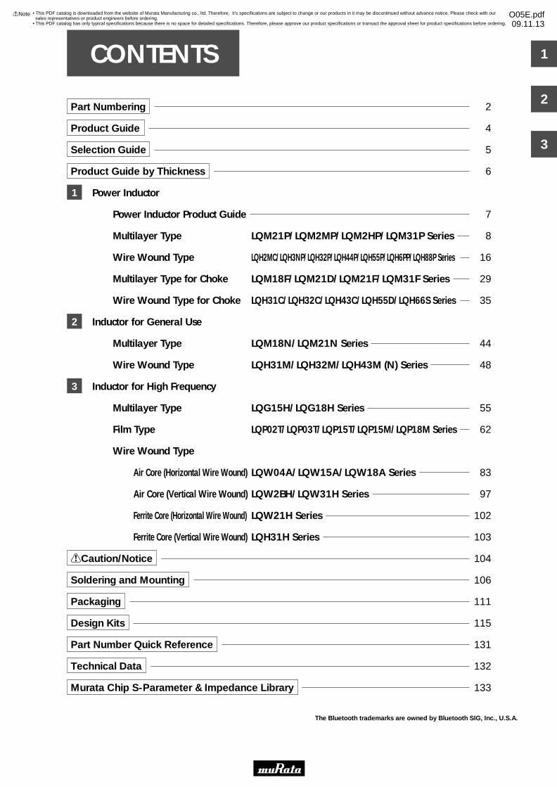
Part Numbering
Product Guide
Selection Guide
Product Guide by Thickness
Power Inductor
Power Inductor Product Guide
Multilayer Type LQM21P/LQM2MP/LQM2HP/LQM31P Series
Wire Wound Type LQH2MC/LQH3NP/LQH32P/LQH44P/LQH55P/LQH6PP/LQH88P Series
Multilayer Type for Choke LQM18F/LQM21D/LQM21F/LQM31F Series
Wire Wound Type for Choke LQH31C/LQH32C/LQH43C/LQH55D/LQH66S Series
Inductor for General Use
Multilayer Type LQM18N/LQM21N Series
Wire Wound Type LQH31M/LQH32M/LQH43M (N) Series
Inductor for High Frequency
Multilayer Type LQG15H/LQG18H Series
Film Type LQP02T/LQP03T/LQP15T/LQP15M/LQP18M Series
Wire Wound Type
Air Core (Horizontal Wire Wound) LQW04A/LQW15A/LQW18A Series
Air Core (Vertical Wire Wound) LQW2BH/LQW31H Series
Ferrite Core (Horizontal Wire Wound) LQW21H Series
Ferrite Core (Vertical Wire Wound) LQH31H Series
!Caution/Notice
Soldering and Mounting
Packaging
Design Kits
Part Number Quick Reference
Technical Data
Murata Chip S-Parameter & Impedance Library
The Bluetooth trademarks are owned by Bluetooth SIG, Inc., U.S.A.
• This PDF catalog is downloaded from the website of Murata Manufacturing co., ltd. Therefore, it’s specifications are subject to change or our products in it may be discontinued without advance notice. Please check with our sales representatives or product engineers before ordering.
• This PDF catalog has only typical specifications because there is no space for detailed specifications. Therefore, please approve our product specifications or transact the approval sheet for product specifications before ordering.
!Note O05E.pdf09.11.13
!Note • Please read rating and !CAUTION (for storage, operating, rating, soldering, mounting and handling) in this catalog to prevent smoking and/or burning, etc.• This catalog has only typical specifications because there is no space for detailed specifications. Therefore, please approve our product specifications or transact the approval sheet for product specifications before ordering.
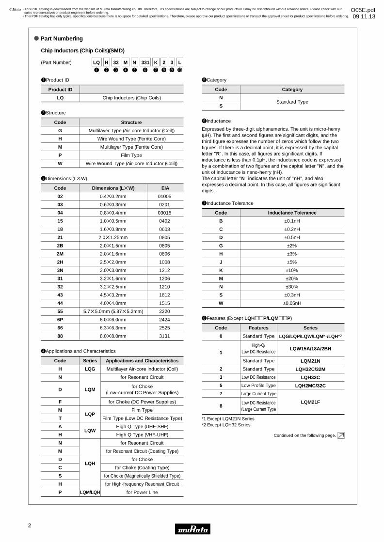
o Part Numbering
(Part Number)
Chip Inductors (Chip Coils)(SMD)
uInductance Tolerance
eDimensions (LgW)
Code
0.4g0.2mm
0.6g0.3mm
0.8g0.4mm
1.0g0.5mm
1.6g0.8mm
2.0g1.25mm
2.0g1.5mm
2.0g1.6mm
2.5g2.0mm
3.0g3.0mm
3.2g1.6mm
3.2g2.5mm
4.5g3.2mm
4.0g4.0mm
5.7g5.0mm (5.87g5.2mm)
6.0g6.0mm
6.3g6.3mm
8.0g8.0mm
Dimensions (LgW)
01005
0201
03015
0402
0603
0805
0805
0806
1008
1212
1206
1210
1812
1515
2220
2424
2525
3131
EIA
02
03
04
15
18
21
2B
2M
2H
3N
31
32
43
44
55
6P
66
88
Code
B
C
D
G
H
J
K
M
N
S
W
±0.1nH
±0.2nH
±0.5nH
±2%
±3%
±5%
±10%
±20%
±30%
±0.3nH
±0.05nH
Inductance Tolerance
qProduct ID
LQ Chip Inductors (Chip Coils)
Product ID
wStructure
Code
G
H
M
P
W
Multilayer Type (Air-core Inductor (Coil))
Wire Wound Type (Ferrite Core)
Multilayer Type (Ferrite Core)
Film Type
Wire Wound Type (Air-core Inductor (Coil))
Structure
rApplications and Characteristics
Code
Multilayer Air-core Inductor (Coil)
for Resonant Circuit
for Choke(Low-current DC Power Supplies)
for Choke (DC Power Supplies)
Film Type
Film Type (Low DC Resistance Type)
High Q Type (UHF-SHF)
High Q Type (VHF-UHF)
for Resonant Circuit
for Resonant Circuit (Coating Type)
for Choke
for Choke (Coating Type)
for Choke (Magnetically Shielded Type)
for High-frequency Resonant Circuit
for Power Line
Applications and Characteristics
H
N
D
F
M
T
A
H
N
M
D
C
S
H
P
Series
LQG
LQM
LQP
LQW
LQH
LQM/LQH
yInductance
Expressed by three-digit alphanumerics. The unit is micro-henry (µH). The first and second figures are significant digits, and the third figure expresses the number of zeros which follow the two figures. If there is a decimal point, it is expressed by the capital letter "R". In this case, all figures are significant digits. If inductance is less than 0.1µH, the inductance code is expressed by a combination of two figures and the capital letter "N", and the unit of inductance is nano-henry (nH).The capital letter "N" indicates the unit of "nH", and also expresses a decimal point. In this case, all figures are significant digits.
iFeatures (Except LQHppP/LQMppP)
0
1
2
3
5
7
8
Standard Type
High-Q/Low DC Resistance
Standard Type
Standard Type
Low DC Resistance
Low Profile Type
Large Current Type
Low DC Resistance/Large Current Type
Code Features Series
tCategory
N
SStandard Type
Code Category
t
N
y
331
q
LQ
u
K
r
M
e
32
w
H
i
2
LQG/LQP/LQW/LQM*1/LQH*2
LQW15A/18A/2BH
LQM21N
LQH32C/32M
LQH32C
LQH2MC/32C
LQM21F
*1 Except LQM21N Series*2 Except LQH32 Series
3
o !0
L
Continued on the following page.
2
• This PDF catalog is downloaded from the website of Murata Manufacturing co., ltd. Therefore, it’s specifications are subject to change or our products in it may be discontinued without advance notice. Please check with our sales representatives or product engineers before ordering.
• This PDF catalog has only typical specifications because there is no space for detailed specifications. Therefore, please approve our product specifications or transact the approval sheet for product specifications before ordering.
!Note O05E.pdf09.11.13
!Note • Please read rating and !CAUTION (for storage, operating, rating, soldering, mounting and handling) in this catalog to prevent smoking and/or burning, etc.• This catalog has only typical specifications because there is no space for detailed specifications. Therefore, please approve our product specifications or transact the approval sheet for product specifications before ordering.
t
N
y
331
q
LQ
u
K
r
M
e
32
w
H
i
2(Part Number)
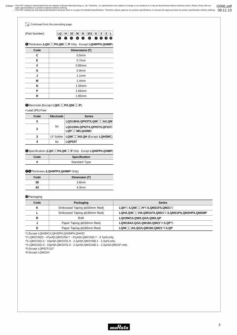
!0Packaging
K
L
B
J
D
LQH*1 /LQWppH*6 /LQM31F/LQM21*2
LQH/LQWppH/LQM31F/LQM21*2 /LQM31P/LQM2HP/LQM2MP
LQH2MC/LQW/LQG/LQM/LQP
LQW18A/LQG/LQM18/LQM21*3 /LQP*5
LQWppA/LQG/LQM18/LQM21*4 /LQP
Embossed Taping (ø330mm Reel)
Embossed Taping (ø180mm Reel)
Bulk
Paper Taping (ø330mm Reel)
Paper Taping (ø180mm Reel)
Code Packaging Series
Continued from the preceding page.
*1 Except LQH2MC/LQH32P/LQH3NP/LQH43C*2 LQM21D(22 - 47µH)/LQM21F(4.7 - 47µH)/LQM21N(2.7 - 4.7µH) only.*3 LQM21D(1.0 - 10µH)/LQM21F(1.0 - 2.2µH)/LQM21N(0.1 - 2.2µH) only.*4 LQM21D(1.0 - 10µH)/LQM21F(1.0 - 2.2µH)/LQM21N(0.1 - 2.2µH)/LQM21P only.*5 Except LQP02T/15T*6 Except LQW21H
3
o !0
L
0
2
3
4
Sn
LF Solder
Au
Code Electrode
LQG18H/LQP03T/LQWppA/LQM
LQG15H/LQP02T/LQP03T/LQP15T/LQPppM/LQH2MC
LQWppH/LQH (Except LQH2MC)
LQP03T
Series
oElectrode (Except LQHppP/LQMppP)
oSpecification (LQHppP/LQMppP Only · Except LQH6PP/LQH88P)
•Lead (Pb) Free
0 Standard Type
Code Specification
ioThickness (LQH6PP/LQH88P Only)
38
43
3.8mm
4.3mm
Code Dimension (T)
iThickness (LQHppP/LQMppP Only · Except LQH6PP/LQH88P)
C
E
0
G
J
M
N
P
R
0.5mm
0.7mm
0.85mm
0.9mm
1.1mm
1.4mm
1.55mm
1.65mm
1.85mm
Code Dimensions (T)
3
• This PDF catalog is downloaded from the website of Murata Manufacturing co., ltd. Therefore, it’s specifications are subject to change or our products in it may be discontinued without advance notice. Please check with our sales representatives or product engineers before ordering.
• This PDF catalog has only typical specifications because there is no space for detailed specifications. Therefore, please approve our product specifications or transact the approval sheet for product specifications before ordering.
!Note O05E.pdf09.11.13

1n 10m 10 100 1000 100001m100µ10µ1µ100n10nPart Number Structure
Size CodeInch (mm)
Inductance Range Rated Current (mA)
Cho
kes
Po
wer
Ind
ucto
rT
ight
Ind
ucta
nce
To
lera
nce
Hig
h F
req
uenc
y R
ang
eG
ener
alF
req
uenc
yR
ang
e
Wire Wound(ferrite core)
Magnetically ShieldedMultilayer
Wire Wound(air core)
Wire Wound(ferrite core)
Magnetically ShieldedMultilayer
Magnetically Shielded
Multilayer
Magnetically ShieldedMultilayer
Film
Wire Wound
Wire Wound
Murata's LQp series of chip inductors (chip coils) consists of compact, high-performance inductors. Their innovative coil and case structures mean low DC resistance and outstanding high-frequency characteristics. The series is designed for a variety of applications, facilitating component selection for individual circuit requirements.
CAUTION: Use rosin-based flux, but not strong acidic flux (with chlorine content exceeding 0.2wt%) when soldering chip inductor (chip coil).
Do not use water-soluble flux.
1206 (3216)LQW31H
1206 (3216)LQH31H
0805 (2015)LQW2BH
0402 (1005)LQG15H
0402 (1005)LQP15M
0402 (1005)LQW15A
03015 (0804)LQW04A
0603 (1608)LQG18H
0603 (1608)LQM18N
0603 (1608)LQW18A
0201 (0603)LQP03T_00
0402 (1005)LQP15T
0603 (1608)LQP18M
2525 (6363)LQH66S
2220 (5750)LQH55D
1206 (3216)LQM31F
0805 (2012)LQM21F
0805 (2012)LQM21D
0603 (1608)LQM18F
0806 (2016)LQH2MC_02
LQH2MC_52
LQH3NP_G0
1206 (3216)LQM31P_00
LQM31P_C0
LQM21P
LQM2HP_E0
LQM2HP_J0
LQH3NP_M0
LQM2MP
LQM2HP_G0
1812 (4532)LQH43C
1210 (3225)LQH32C_23/_33
1210 (3225)LQH32C_53
1206 (3216)LQH31C
0805 (2012)LQM21N
1206 (3216)LQH31M
1210 (3225)LQH32M
1812 (4532)LQH43M(N)
1210 (3225)LQH32P
1515 (4040)LQH44P_J0
1515 (4040)LQH44P_P0
2220 (5852)LQH55P
2424 (6060)LQH6PP
3131 (8080)LQH88P
1212 (3030)
0806 (2016)
1206 (3216)
0805 (2012)
1008 (2520)
1008 (2520)
0806 (2016)
1008 (2520)
0805 (2012)LQW21H
0201 (0603)LQP03T_02
0201 (0603)LQP03T_04
01005 (0402)LQP02T
1212 (3030)
LQH3NP_J0 1212 (3030)
8.8nH 100nH
1.0nH
10µH
10µH1.0µH
22µH1.0µH
1.0µH 250µH
560nH
22µH
270nH
82µH1.0µH
54nH 880nH
2.7nH 470nH
1.0nH 33nH
1.3nH 120nH
1.1nH 33nH
100nH1.2nH
47nH 2.2µH
470nH2.2nH
0.6nH 56nH
0.6nH 120nH
0.6nH 56nH
0.4nH 18nH
18nH1.0nH
100nH1.3nH
270nH 10mH
120nH 10mH
47µH1.0µH
47µH1.0µH
47µH1.0µH
22µH1.0µH
47µH1.0µH
470µH1.0µH
1.0µH
150nH 560µH
120nH 100µH
100µH
1.0µH 100µH
1.0µH 100µH
1.0µH 100µH
100nH 4.7µH
150nH 100µH
560µH1.0µH
2.2mH1.0µH
1.0µH
470nH 2.2µH
470nH 4.7µH
470nH 2.2µH
470nH 4.7µH
470nH 4.7µH
3.3µH
470nH 2.2µH
470nH
22µH1.2µH
: E-24 or Higher
: E-12
: Other
Inductance Lineup
*There are some items which do not match to E step.
110 300
300 500
140 320
100 840
40 850
50 420
80 300
60 400
50 300
140 990
110 1200
75 1400
160 1900
230 750
75 160
180 920
15 50
30 250
45 250
40 445
30 500
600 1300
1100 1600
1000 1500
1100 1800
1500
700 1400
900 1300
90 485
130 595
200 1400
200 1620
80 1525
450 2550
300 1530
790 2450
670 2600
800 4300
1000 8000
50 150
7 60
7 220
70
80 970
60 1450
100 1000
90 1080
50 6000
50 6000
Product Guide
!Note • Please read rating and !CAUTION (for storage, operating, rating, soldering, mounting and handling) in this catalog to prevent smoking and/or burning, etc.• This catalog has only typical specifications because there is no space for detailed specifications. Therefore, please approve our product specifications or transact the approval sheet for product specifications before ordering.
4
• This PDF catalog is downloaded from the website of Murata Manufacturing co., ltd. Therefore, it’s specifications are subject to change or our products in it may be discontinued without advance notice. Please check with our sales representatives or product engineers before ordering.
• This PDF catalog has only typical specifications because there is no space for detailed specifications. Therefore, please approve our product specifications or transact the approval sheet for product specifications before ordering.
!Note O05E.pdf09.11.13
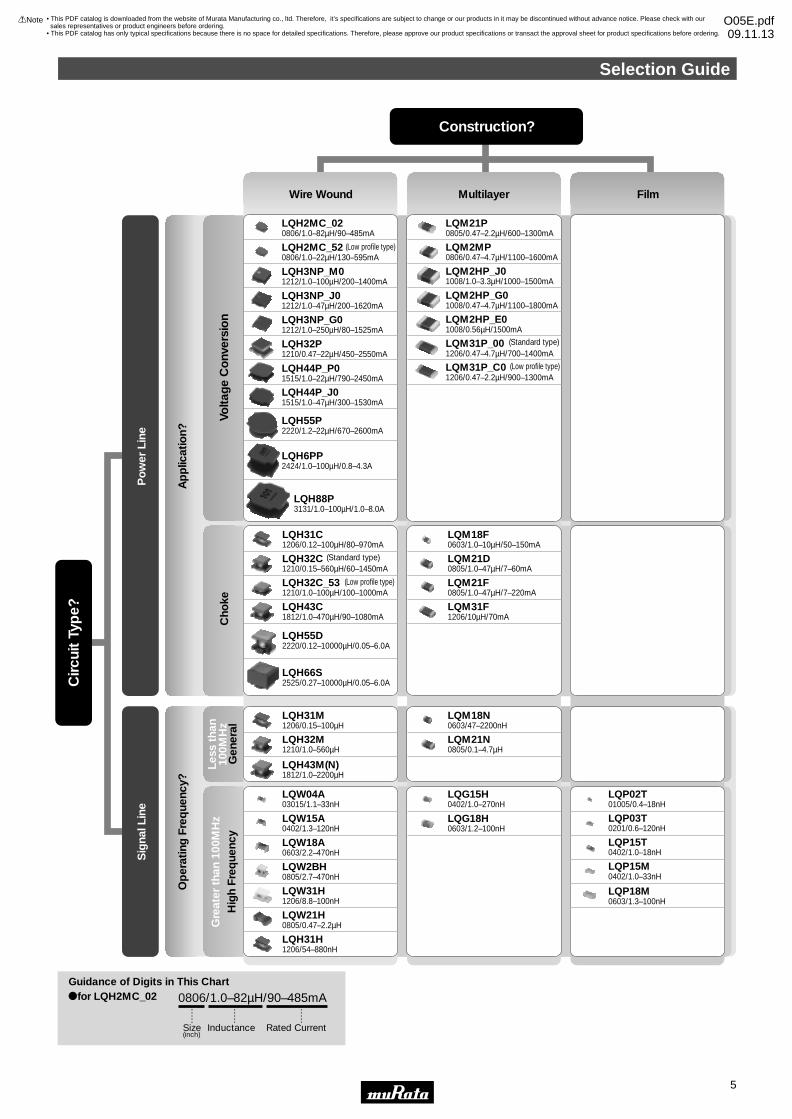
LQH2MC_020806/1.0–82µH/90–485mA
LQH2MC_520806/1.0–22µH/130–595mA
LQH3NP_M01212/1.0–100µH/200–1400mA
LQH3NP_J01212/1.0–47µH/200–1620mA
LQH3NP_G01212/1.0–250µH/80–1525mA
LQH32P1210/0.47–22µH/450–2550mA
LQH44P_J01515/1.0–47µH/300–1530mA
LQH44P_P01515/1.0–22µH/790–2450mA
LQH55P2220/1.2–22µH/670–2600mA
LQH6PP2424/1.0–100µH/0.8–4.3A
LQH88P3131/1.0–100µH/1.0–8.0A
LQM21P0805/0.47–2.2µH/600–1300mA
LQM2MP0806/0.47–4.7µH/1100–1600mA
LQM2HP_J01008/1.0–3.3µH/1000–1500mA
LQM2HP_G01008/0.47–4.7µH/1100–1800mA
LQM2HP_E01008/0.56µH/1500mA
LQM31P_C01206/0.47–2.2µH/900–1300mA
LQM31P_001206/0.47–4.7µH/700–1400mA
LQH31C1206/0.12–100µH/80–970mA
LQH32C1210/0.15–560µH/60–1450mA
LQH32C_531210/1.0–100µH/100–1000mA
LQH43C1812/1.0–470µH/90–1080mA
LQH55D2220/0.12–10000µH/0.05–6.0A
LQH66S2525/0.27–10000µH/0.05–6.0A
LQM18F0603/1.0–10µH/50–150mA
LQM21D0805/1.0–47µH/7–60mA
LQM21F0805/1.0–47µH/7–220mA
LQM31F1206/10µH/70mA
(Low profile type)
(Low profile type)
(Standard type)
(Standard type)
(Low profile type)
LQW04A03015/1.1–33nH
LQW15A0402/1.3–120nH
LQW18A0603/2.2–470nH
LQW2BH0805/2.7–470nH
LQW31H1206/8.8–100nH
LQW21H0805/0.47–2.2µH
LQG15H0402/1.0–270nH
LQG18H0603/1.2–100nH
LQH31H1206/54–880nH
LQP02T01005/0.4–18nH
LQP03T0201/0.6–120nH
LQP15T0402/1.0–18nH
LQP15M0402/1.0–33nH
LQP18M0603/1.3–100nH
LQH31M1206/0.15–100µH
LQH32M1210/1.0–560µH
LQH43M(N)1812/1.0–2200µH
LQM18N0603/47–2200nH
LQM21N0805/0.1–4.7µH
0806/1.0–82µH/90–485mA
Op
erat
ing
Fre
que
ncy?
Ap
plic
atio
n?
Gen
eral
Hig
h F
req
uenc
yVo
ltag
e C
onv
ersi
on
Cho
ke
Po
wer
Lin
eS
igna
l Lin
e
Circ
uit
Typ
e?
Less
tha
n10
0MH
zG
reat
er t
han
100M
Hz
Wire Wound Multilayer Film
ofor LQH2MC_02Guidance of Digits in This Chart
Size(inch)
Inductance Rated Current
Construction?
Selection Guide
!Note • Please read rating and !CAUTION (for storage, operating, rating, soldering, mounting and handling) in this catalog to prevent smoking and/or burning, etc.• This catalog has only typical specifications because there is no space for detailed specifications. Therefore, please approve our product specifications or transact the approval sheet for product specifications before ordering.
5
• This PDF catalog is downloaded from the website of Murata Manufacturing co., ltd. Therefore, it’s specifications are subject to change or our products in it may be discontinued without advance notice. Please check with our sales representatives or product engineers before ordering.
• This PDF catalog has only typical specifications because there is no space for detailed specifications. Therefore, please approve our product specifications or transact the approval sheet for product specifications before ordering.
!Note O05E.pdf09.11.13
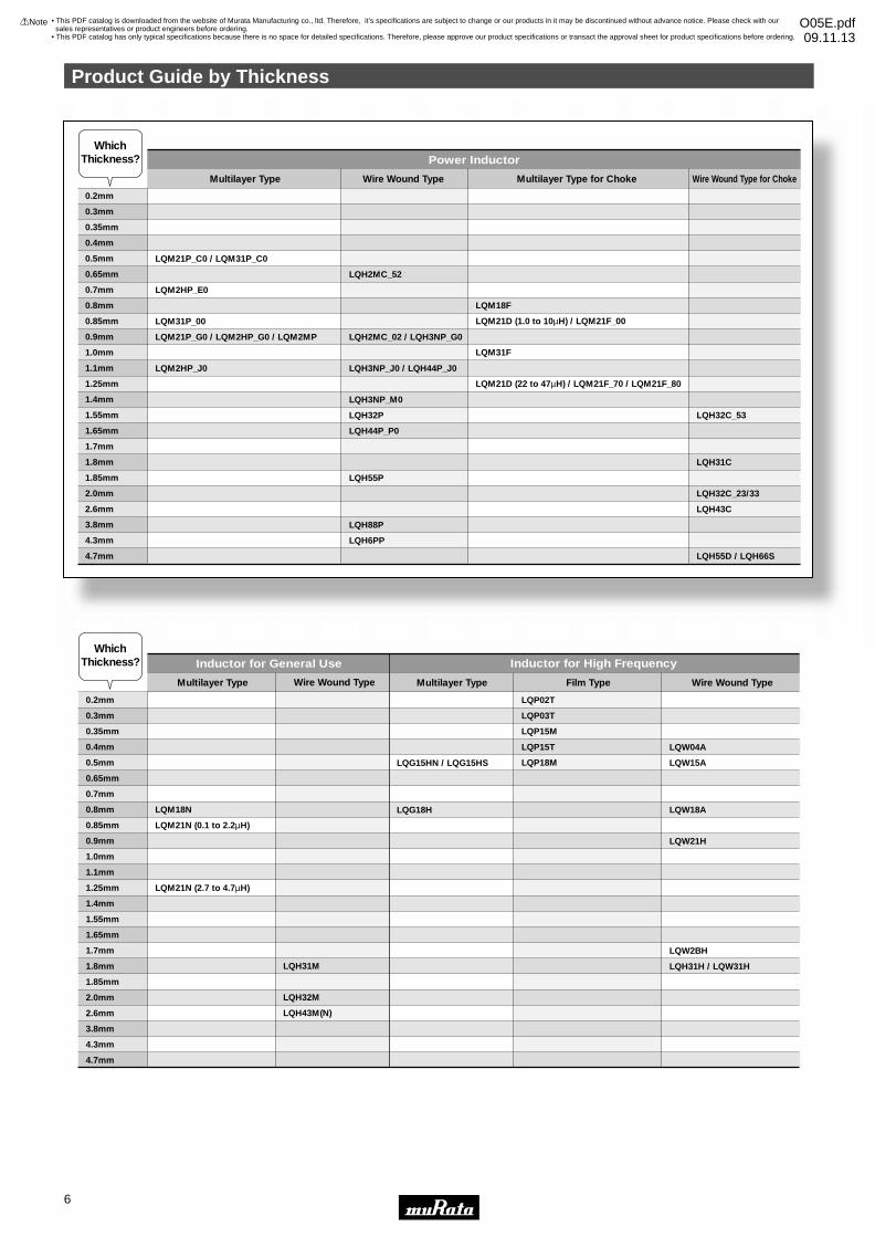
0.2mm
0.3mm
0.35mm
0.4mm
0.5mm
0.65mm
0.7mm
0.8mm
0.85mm
0.9mm
1.0mm
1.1mm
1.25mm
1.4mm
1.55mm
1.65mm
1.7mm
1.8mm
1.85mm
2.0mm
2.6mm
3.8mm
4.3mm
4.7mm
LQM21P_C0 / LQM31P_C0
LQM2HP_E0
LQM31P_00
LQM21P_G0 / LQM2HP_G0 / LQM2MP
LQM2HP_J0
LQH2MC_52
LQH2MC_02 / LQH3NP_G0
LQH3NP_J0 / LQH44P_J0
LQH3NP_M0
LQH32P
LQH44P_P0
LQH55P
LQH88P
LQH6PP
LQM18F
LQM21D (1.0 to 10µH) / LQM21F_00
LQM31F
LQM21D (22 to 47µH) / LQM21F_70 / LQM21F_80
LQH32C_53
LQH31C
LQH32C_23/33
LQH43C
LQH55D / LQH66S
0.2mm
0.3mm
0.35mm
0.4mm
0.5mm
0.65mm
0.7mm
0.8mm
0.85mm
0.9mm
1.0mm
1.1mm
1.25mm
1.4mm
1.55mm
1.65mm
1.7mm
1.8mm
1.85mm
2.0mm
2.6mm
3.8mm
4.3mm
4.7mm
LQM18N
LQM21N (0.1 to 2.2µH)
LQM21N (2.7 to 4.7µH)
LQH31M
LQH32M
LQH43M(N)
LQG15HN / LQG15HS
LQG18H
LQP02T
LQP03T
LQP15M
LQP15T
LQP18M
LQW04A
LQW15A
LQW18A
LQW21H
LQW2BH
LQH31H / LQW31H
Multilayer Type
Power InductorWhich
Thickness?
WhichThickness?
Wire Wound Type for ChokeMultilayer Type for ChokeWire Wound Type
Multilayer Type Wire Wound Type
Inductor for General Use Inductor for High Frequency
Multilayer Type Film Type Wire Wound Type
Product Guide by Thickness
!Note • Please read rating and !CAUTION (for storage, operating, rating, soldering, mounting and handling) in this catalog to prevent smoking and/or burning, etc.• This catalog has only typical specifications because there is no space for detailed specifications. Therefore, please approve our product specifications or transact the approval sheet for product specifications before ordering.
6
• This PDF catalog is downloaded from the website of Murata Manufacturing co., ltd. Therefore, it’s specifications are subject to change or our products in it may be discontinued without advance notice. Please check with our sales representatives or product engineers before ordering.
• This PDF catalog has only typical specifications because there is no space for detailed specifications. Therefore, please approve our product specifications or transact the approval sheet for product specifications before ordering.
!Note O05E.pdf09.11.13
1
!Note • Please read rating and !CAUTION (for storage, operating, rating, soldering, mounting and handling) in this catalog to prevent smoking and/or burning, etc.• This catalog has only typical specifications because there is no space for detailed specifications. Therefore, please approve our product specifications or transact the approval sheet for product specifications before ordering.
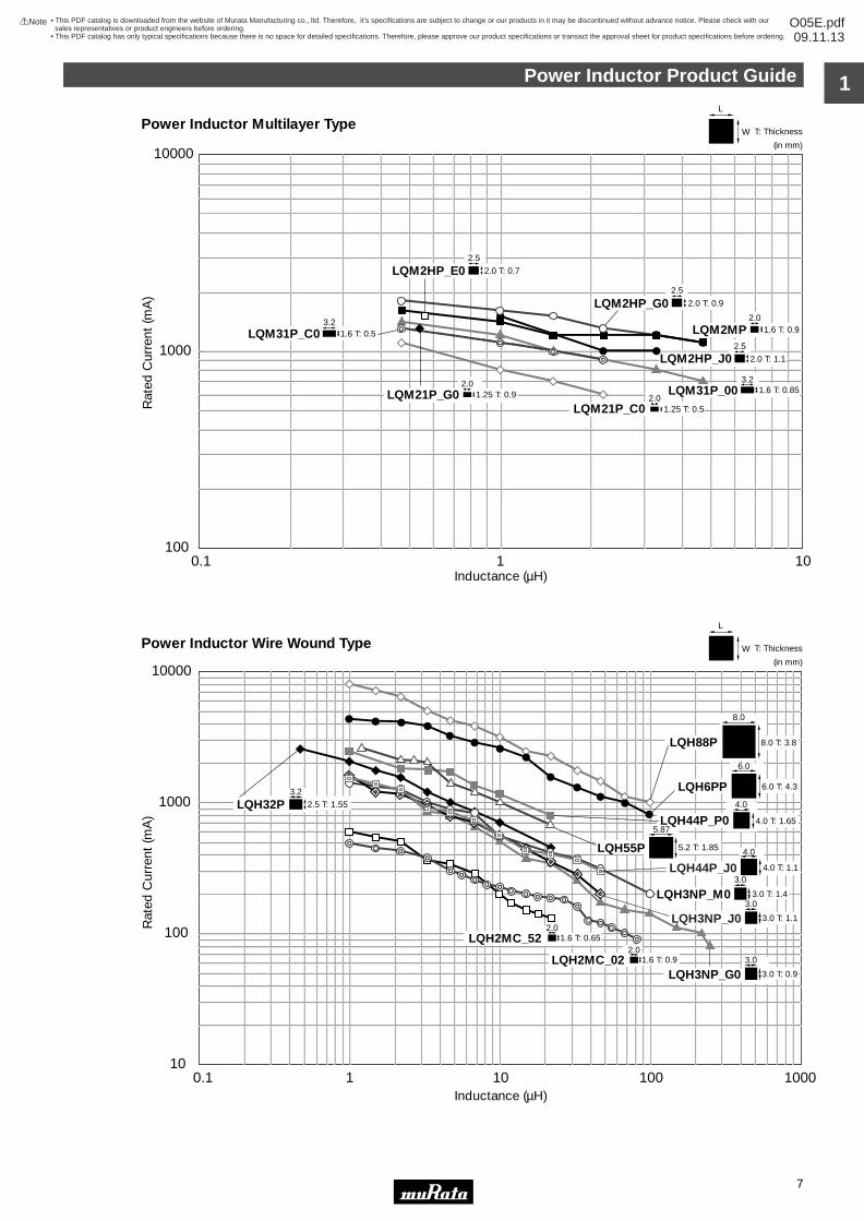
Power Inductor Product Guide
7
W T: Thickness
(in mm)
L
W T: Thickness
L
2.0 T: 0.7
2.5
2.0 T: 0.9
2.5
2.0 T: 1.1
2.5
3.2
1.6 T: 0.9
1.6 T: 0.85
3.21.6 T: 0.5
2.0
1.25 T: 0.52.01.25 T: 0.9
2.0
(in mm)
6.0 T: 4.3
6.0
5.2 T: 1.85
5.874.0 T: 1.65
4.0
4.0 T: 1.1
4.0
3.0 T: 1.4
3.0
3.0 T: 1.1
3.0
2.5 T: 1.553.2
1.6 T: 0.92.0
2.01.6 T: 0.65
8.0 T: 3.8
8.0
3.0 T: 0.9
3.0
10
100
1000
10000
0.1 1 10 100 1000Inductance (µH)
Rat
ed C
urre
nt (m
A)
Inductance (µH)
Rat
ed C
urre
nt (m
A)
LQH3NP_G0
LQH88P
LQH44P_P0
LQH55P
LQH32P
LQH3NP_M0
LQH2MC_52
LQH2MC_02
LQH6PP
100
1000
10000
0.1 1 10
LQM21P_C0
LQM2HP_E0
LQM21P_G0
LQM31P_C0
LQM2HP_G0
LQM2HP_J0
LQM31P_00
LQM2MP
LQH44P_J0
LQH3NP_J0
Power Inductor Multilayer Type
Power Inductor Wire Wound Type
• This PDF catalog is downloaded from the website of Murata Manufacturing co., ltd. Therefore, it’s specifications are subject to change or our products in it may be discontinued without advance notice. Please check with our sales representatives or product engineers before ordering.
• This PDF catalog has only typical specifications because there is no space for detailed specifications. Therefore, please approve our product specifications or transact the approval sheet for product specifications before ordering.
!Note O05E.pdf09.11.13
1
!Note • Please read rating and !CAUTION (for storage, operating, rating, soldering, mounting and handling) in this catalog to prevent smoking and/or burning, etc.• This catalog has only typical specifications because there is no space for detailed specifications. Therefore, please approve our product specifications or transact the approval sheet for product specifications before ordering.
8
• This PDF catalog is downloaded from the website of Murata Manufacturing co., ltd. Therefore, it’s specifications are subject to change or our products in it may be discontinued without advance notice. Please check with our sales representatives or product engineers before ordering.
• This PDF catalog has only typical specifications because there is no space for detailed specifications. Therefore, please approve our product specifications or transact the approval sheet for product specifications before ordering.
!Note O05E.pdf09.11.13
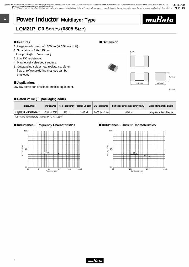
Power Inductor Multilayer Type
LQM21P_G0 Series (0805 Size)
1. Large rated current of 1300mA (at 0.54 micro H).2. Small size in 2.0x1.25mm Low profile(h=1.0mm max.)3. Low DC resistance.4. Magnetically shielded structure.5. Outstanding solder heat resistance, either flow or reflow soldering methods can be employed.
ApplicationsDC-DC converter circuits for mobile equipment.
Dimension Features
Rated Value (p: packaging code)
0.5±0.2
2.0±0.15 1.25±0.15
0.9±0.1
(in mm)
Part Number Inductance Test Frequency Rated Current DC Resistance Self Resonance Frequency (min.) Class of Magnetic Shield
LQM21PNR54MG0p 0.54µH±20% 1MHz 1300mA 0.075ohm±25% 100MHz Magnetic shield of ferrite
Operating Temperature Range: -55°C to +125°C
0.54µH
0.1
1.0
10.0
0.1 1 10 100 1000 10000Frequency (MHz)
Indu
ctan
ce (
µH)
Inductance - Frequency Characteristics
0.1
1.0
10.0
10 100 1000 10000DC Current (mA)
Indu
ctan
ce (
µH)
0.54µH
Inductance - Current Characteristics

1
!Note • Please read rating and !CAUTION (for storage, operating, rating, soldering, mounting and handling) in this catalog to prevent smoking and/or burning, etc.• This catalog has only typical specifications because there is no space for detailed specifications. Therefore, please approve our product specifications or transact the approval sheet for product specifications before ordering.
9
• This PDF catalog is downloaded from the website of Murata Manufacturing co., ltd. Therefore, it’s specifications are subject to change or our products in it may be discontinued without advance notice. Please check with our sales representatives or product engineers before ordering.
• This PDF catalog has only typical specifications because there is no space for detailed specifications. Therefore, please approve our product specifications or transact the approval sheet for product specifications before ordering.
!Note O05E.pdf09.11.13
Power Inductor Multilayer Type
LQM21P_C0 Series (0805 Size)
1. Small size in 2.0x1.25mm2. Low profile (h=0.55mm max.) 3. Large rated current of 1100mA 4. Magnetically shielded structure5. Outstanding solder heat resistance, either flow or reflow soldering methods can be employed.
ApplicationsDC-DC converter circuits for mobile equipment
Dimension Features
Rated Value (p: packaging code)
ElectrodeFerrite0.5±0.2
2.0±0.2
1.25±0.2
0.5±0.05
(in mm)
Part Number Inductance Test Frequency Rated Current DC Resistance Self Resonance Frequency (min.) Class of Magnetic Shield
LQM21PNR47MC0p 0.47µH±20% 1MHz 1100mA 0.12ohm±25% 100MHz Magnetic shield of ferrite
LQM21PN1R0MC0p 1.0µH±20% 1MHz 800mA 0.19ohm±25% 90MHz Magnetic shield of ferrite
LQM21PN1R5MC0p 1.5µH±20% 1MHz 700mA 0.26ohm±25% 70MHz Magnetic shield of ferrite
LQM21PN2R2MC0p 2.2µH±20% 1MHz 600mA 0.34ohm±25% 50MHz Magnetic shield of ferrite
Operating Temperature Range: -55°C to +125°C
Indu
ctan
ce (
µH)
Frequency (MHz)
0.1
1
10
10001001010.1
0.47µH
1.0µH
1.5µH
2.2µH
Inductance - Frequency Characteristics
0.1
1
10
10000100010010
DC Current (mA)
Indu
ctan
ce (
µH)
2.2µH
1.5µH
1.0µH
0.47µH
Inductance - Current Characteristics

1
!Note • Please read rating and !CAUTION (for storage, operating, rating, soldering, mounting and handling) in this catalog to prevent smoking and/or burning, etc.• This catalog has only typical specifications because there is no space for detailed specifications. Therefore, please approve our product specifications or transact the approval sheet for product specifications before ordering.
10
• This PDF catalog is downloaded from the website of Murata Manufacturing co., ltd. Therefore, it’s specifications are subject to change or our products in it may be discontinued without advance notice. Please check with our sales representatives or product engineers before ordering.
• This PDF catalog has only typical specifications because there is no space for detailed specifications. Therefore, please approve our product specifications or transact the approval sheet for product specifications before ordering.
!Note O05E.pdf09.11.13
Power Inductor Multilayer Type
LQM2MP_G0 Series (0806 Size)
1. Large rated current of 1400mA (1.0 micro H)2. Small size in 2.0x1.6mm and low profile in 1.0mm max.3. Low DC resistance is realized.4. Magnetically shielded structure 5. Applicable soldering methods are both flow soldering and reflow soldering.
Applications DC-DC converter circuits for mobile equipment
Dimension Features
Rated Value (p: packaging code)
(in mm)
2.0±0.15
0.5±0.2
1.6±0.15
0.9±
0.1
Part Number Inductance Test Frequency Rated Current DC Resistance Self Resonance Frequency (min.) Class of Magnetic Shield
LQM2MPNR47NG0p 0.47µH±30% 1MHz 1600mA 0.06ohm±25% 100MHz Magnetic shield of ferrite
LQM2MPN1R0NG0p 1.0µH±30% 1MHz 1400mA 0.085ohm±25% 60MHz Magnetic shield of ferrite
LQM2MPN1R5NG0p 1.5µH±30% 1MHz 1200mA 0.11ohm±25% 50MHz Magnetic shield of ferrite
LQM2MPN2R2NG0p 2.2µH±30% 1MHz 1200mA 0.11ohm±25% 40MHz Magnetic shield of ferrite
LQM2MPN3R3NG0p 3.3µH±30% 1MHz 1200mA 0.12ohm±25% 30MHz Magnetic shield of ferrite
LQM2MPN4R7NG0p 4.7µH±30% 1MHz 1100mA 0.14ohm±25% 20MHz Magnetic shield of ferrite
Operating Temperature Range: -55°C to +125°C
0.1
10
1
Indu
ctan
ce (
µH)
0.1 1 10 100Frequency (MHz)
0.47µH
1.0µH
1.5µH
2.2µH
4.7µH
3.3µH
Inductance - Frequency Characteristics
0.1
10
1
Indu
ctan
ce (
µH)
1 10 1000 10000100Current (mA)
0.47µH
4.7µH 3.3µH
1.5µH
2.2µH
1.0µH
Inductance - Current Characteristics
1
!Note • Please read rating and !CAUTION (for storage, operating, rating, soldering, mounting and handling) in this catalog to prevent smoking and/or burning, etc.• This catalog has only typical specifications because there is no space for detailed specifications. Therefore, please approve our product specifications or transact the approval sheet for product specifications before ordering.
11
• This PDF catalog is downloaded from the website of Murata Manufacturing co., ltd. Therefore, it’s specifications are subject to change or our products in it may be discontinued without advance notice. Please check with our sales representatives or product engineers before ordering.
• This PDF catalog has only typical specifications because there is no space for detailed specifications. Therefore, please approve our product specifications or transact the approval sheet for product specifications before ordering.
!Note O05E.pdf09.11.13
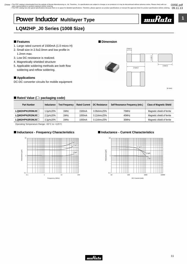
Power Inductor Multilayer Type
LQM2HP_J0 Series (1008 Size)
1. Large rated current of 1500mA (1.0 micro H)2. Small size in 2.5x2.0mm and low profile in 1.2mm max.3. Low DC resistance is realized.4. Magnetically shielded structure5. Applicable soldering methods are both flow soldering and reflow soldering.
ApplicationsDC-DC converter circuits for mobile equipment
Dimension Features
Rated Value (p: packaging code)
2.5±0.2
0.6±0.2
2.0±0.2
(in mm)
1.1±
0.1
Part Number Inductance Test Frequency Rated Current DC Resistance Self Resonance Frequency (min.) Class of Magnetic Shield
LQM2HPN1R0MJ0p 1.0µH±20% 1MHz 1500mA 0.09ohm±25% 70MHz Magnetic shield of ferrite
LQM2HPN2R2MJ0p 2.2µH±20% 1MHz 1000mA 0.12ohm±25% 40MHz Magnetic shield of ferrite
LQM2HPN3R3MJ0p 3.3µH±20% 1MHz 1000mA 0.12ohm±25% 30MHz Magnetic shield of ferrite
Operating Temperature Range: -55°C to +125°C
0.1
1
10
Indu
ctan
ce (
µH)
0.1 1 10 100
Frequency (MHz)
1.0µH
2.2µH
3.3µH
Inductance - Frequency Characteristics
0.1
1
10
10 100 1000 10000
DC Current (mA)
Indu
ctan
ce (
µH)
1.0µH
3.3µH
2.2µH
Inductance - Current Characteristics
1
!Note • Please read rating and !CAUTION (for storage, operating, rating, soldering, mounting and handling) in this catalog to prevent smoking and/or burning, etc.• This catalog has only typical specifications because there is no space for detailed specifications. Therefore, please approve our product specifications or transact the approval sheet for product specifications before ordering.
12
• This PDF catalog is downloaded from the website of Murata Manufacturing co., ltd. Therefore, it’s specifications are subject to change or our products in it may be discontinued without advance notice. Please check with our sales representatives or product engineers before ordering.
• This PDF catalog has only typical specifications because there is no space for detailed specifications. Therefore, please approve our product specifications or transact the approval sheet for product specifications before ordering.
!Note O05E.pdf09.11.13
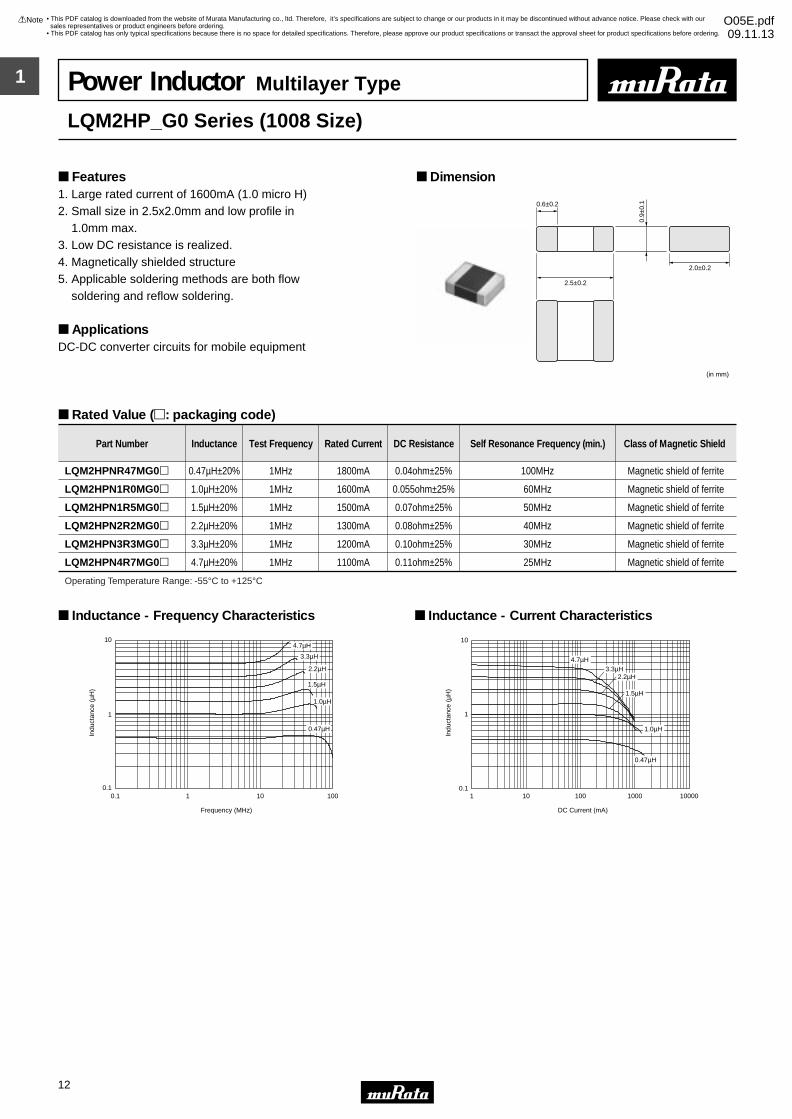
Power Inductor Multilayer Type
LQM2HP_G0 Series (1008 Size)
1. Large rated current of 1600mA (1.0 micro H)2. Small size in 2.5x2.0mm and low profile in 1.0mm max.3. Low DC resistance is realized.4. Magnetically shielded structure 5. Applicable soldering methods are both flow soldering and reflow soldering.
Applications DC-DC converter circuits for mobile equipment
Dimension Features
Rated Value (p: packaging code)
2.5±0.2
0.6±0.2
2.0±0.2
(in mm)
0.9±
0.1
Part Number Inductance Test Frequency Rated Current DC Resistance Self Resonance Frequency (min.) Class of Magnetic Shield
LQM2HPNR47MG0p 0.47µH±20% 1MHz 1800mA 0.04ohm±25% 100MHz Magnetic shield of ferrite
LQM2HPN1R0MG0p 1.0µH±20% 1MHz 1600mA 0.055ohm±25% 60MHz Magnetic shield of ferrite
LQM2HPN1R5MG0p 1.5µH±20% 1MHz 1500mA 0.07ohm±25% 50MHz Magnetic shield of ferrite
LQM2HPN2R2MG0p 2.2µH±20% 1MHz 1300mA 0.08ohm±25% 40MHz Magnetic shield of ferrite
LQM2HPN3R3MG0p 3.3µH±20% 1MHz 1200mA 0.10ohm±25% 30MHz Magnetic shield of ferrite
LQM2HPN4R7MG0p 4.7µH±20% 1MHz 1100mA 0.11ohm±25% 25MHz Magnetic shield of ferrite
Operating Temperature Range: -55°C to +125°C
0.1
1
10
Indu
ctan
ce (
µH)
0.1 1 10 100
Frequency (MHz)
4.7µH
3.3µH
2.2µH
1.5µH
1.0µH
0.47µH
Inductance - Frequency Characteristics
Indu
ctan
ce (
µH)
0.1
1
10
1 10 100 1000 10000
DC Current (mA)
0.47µH
4.7µH
1.0µH
2.2µH3.3µH
1.5µH
Inductance - Current Characteristics
1
!Note • Please read rating and !CAUTION (for storage, operating, rating, soldering, mounting and handling) in this catalog to prevent smoking and/or burning, etc.• This catalog has only typical specifications because there is no space for detailed specifications. Therefore, please approve our product specifications or transact the approval sheet for product specifications before ordering.
13
• This PDF catalog is downloaded from the website of Murata Manufacturing co., ltd. Therefore, it’s specifications are subject to change or our products in it may be discontinued without advance notice. Please check with our sales representatives or product engineers before ordering.
• This PDF catalog has only typical specifications because there is no space for detailed specifications. Therefore, please approve our product specifications or transact the approval sheet for product specifications before ordering.
!Note O05E.pdf09.11.13
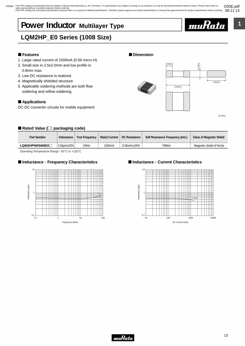
Power Inductor Multilayer Type
LQM2HP_E0 Series (1008 Size)
1. Large rated current of 1500mA (0.56 micro H)2. Small size in 2.5x2.0mm and low profile in 0.8mm max.3. Low DC resistance is realized.4. Magnetically shielded structure5. Applicable soldering methods are both flow soldering and reflow soldering.
Applications DC-DC converter circuits for mobile equipment
Dimension Features
Rated Value (p: packaging code)
2.5±0.2
0.6±0.2
2.0±0.2
(in mm)
0.7±
0.1
Part Number Inductance Test Frequency Rated Current DC Resistance Self Resonance Frequency (min.) Class of Magnetic Shield
LQM2HPNR56ME0p 0.56µH±20% 1MHz 1500mA 0.06ohm±25% 70MHz Magnetic shield of ferrite
Operating Temperature Range: -55°C to +125°C
0.1
1
10
Indu
ctan
ce (
µH)
0.1 1 10 100
Frequency (MHz)
0.56µH
Inductance - Frequency Characteristics
0.1
1
10
10 100 1000 10000
DC Current (mA)
Indu
ctan
ce (
µH)
0.56µH
Inductance - Current Characteristics
1
!Note • Please read rating and !CAUTION (for storage, operating, rating, soldering, mounting and handling) in this catalog to prevent smoking and/or burning, etc.• This catalog has only typical specifications because there is no space for detailed specifications. Therefore, please approve our product specifications or transact the approval sheet for product specifications before ordering.
14
• This PDF catalog is downloaded from the website of Murata Manufacturing co., ltd. Therefore, it’s specifications are subject to change or our products in it may be discontinued without advance notice. Please check with our sales representatives or product engineers before ordering.
• This PDF catalog has only typical specifications because there is no space for detailed specifications. Therefore, please approve our product specifications or transact the approval sheet for product specifications before ordering.
!Note O05E.pdf09.11.13
Power Inductor Multilayer Type
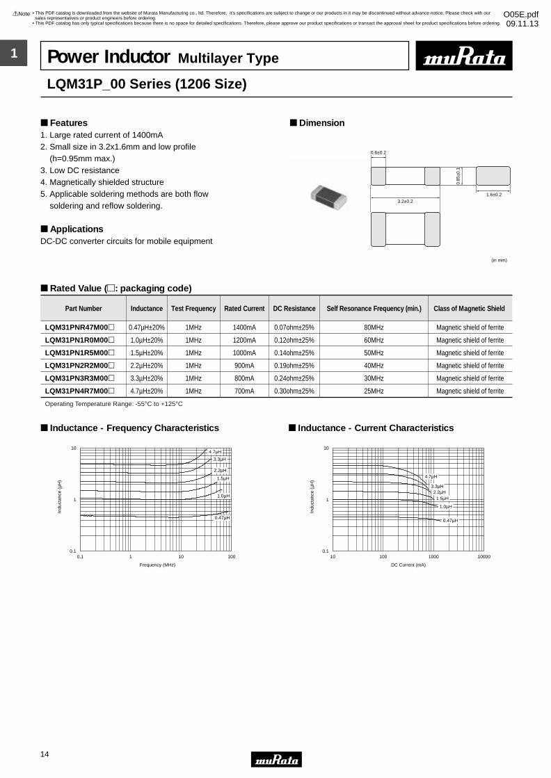
LQM31P_00 Series (1206 Size)
1. Large rated current of 1400mA2. Small size in 3.2x1.6mm and low profile (h=0.95mm max.) 3. Low DC resistance 4. Magnetically shielded structure5. Applicable soldering methods are both flow soldering and reflow soldering.
ApplicationsDC-DC converter circuits for mobile equipment
Dimension Features
Rated Value (p: packaging code)
3.2±0.2
0.6±0.2
1.6±0.2
(in mm)
0.85
±0.1
Part Number Inductance Test Frequency Rated Current DC Resistance Self Resonance Frequency (min.) Class of Magnetic Shield
LQM31PNR47M00p 0.47µH±20% 1MHz 1400mA 0.07ohm±25% 80MHz Magnetic shield of ferrite
LQM31PN1R0M00p 1.0µH±20% 1MHz 1200mA 0.12ohm±25% 60MHz Magnetic shield of ferrite
LQM31PN1R5M00p 1.5µH±20% 1MHz 1000mA 0.14ohm±25% 50MHz Magnetic shield of ferrite
LQM31PN2R2M00p 2.2µH±20% 1MHz 900mA 0.19ohm±25% 40MHz Magnetic shield of ferrite
LQM31PN3R3M00p 3.3µH±20% 1MHz 800mA 0.24ohm±25% 30MHz Magnetic shield of ferrite
LQM31PN4R7M00p 4.7µH±20% 1MHz 700mA 0.30ohm±25% 25MHz Magnetic shield of ferrite
Operating Temperature Range: -55°C to +125°C
0.1 1 10 100
Frequency (MHz)
0.1
1
10
Indu
ctan
ce (
µH)
4.7µH
3.3µH
2.2µH
1.5µH
1.0µH
0.47µH
Inductance - Frequency Characteristics
Indu
ctan
ce (
µH)
10 100 1000 10000
DC Current (mA)
0.1
1
10
4.7µH
3.3µH2.2µH
1.5µH
1.0µH
0.47µH
Inductance - Current Characteristics
1
!Note • Please read rating and !CAUTION (for storage, operating, rating, soldering, mounting and handling) in this catalog to prevent smoking and/or burning, etc.• This catalog has only typical specifications because there is no space for detailed specifications. Therefore, please approve our product specifications or transact the approval sheet for product specifications before ordering.
15
• This PDF catalog is downloaded from the website of Murata Manufacturing co., ltd. Therefore, it’s specifications are subject to change or our products in it may be discontinued without advance notice. Please check with our sales representatives or product engineers before ordering.
• This PDF catalog has only typical specifications because there is no space for detailed specifications. Therefore, please approve our product specifications or transact the approval sheet for product specifications before ordering.
!Note O05E.pdf09.11.13
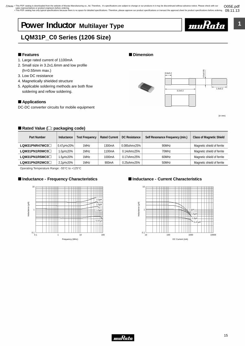
Power Inductor Multilayer Type
LQM31P_C0 Series (1206 Size)
1. Large rated current of 1100mA2. Small size in 3.2x1.6mm and low profile (h=0.55mm max.) 3. Low DC resistance 4. Magnetically shielded structure5. Applicable soldering methods are both flow soldering and reflow soldering.
ApplicationsDC-DC converter circuits for mobile equipment
Dimension Features
Rated Value (p: packaging code)
3.2±0.2
0.6±0.2
1.6±0.2
(in mm)
0.5±
0.05
Part Number Inductance Test Frequency Rated Current DC Resistance Self Resonance Frequency (min.) Class of Magnetic Shield
LQM31PNR47MC0p 0.47µH±20% 1MHz 1300mA 0.085ohm±25% 90MHz Magnetic shield of ferrite
LQM31PN1R0MC0p 1.0µH±20% 1MHz 1100mA 0.14ohm±25% 70MHz Magnetic shield of ferrite
LQM31PN1R5MC0p 1.5µH±20% 1MHz 1000mA 0.17ohm±25% 60MHz Magnetic shield of ferrite
LQM31PN2R2MC0p 2.2µH±20% 1MHz 900mA 0.25ohm±25% 50MHz Magnetic shield of ferrite
Operating Temperature Range: -55°C to +125°C
0.1
1
10
1001010.1
Frequency (MHz)
Indu
ctan
ce (
µH)
2.2µH
1.5µH
1.0µH
0.47µH
Inductance - Frequency Characteristics
0.1
1
10
10000100010010
DC Current (mA)
Indu
ctan
ce (
µH)
2.2µH
1.5µH
1.0µH
0.47µH
Inductance - Current Characteristics
1
!Note • Please read rating and !CAUTION (for storage, operating, rating, soldering, mounting and handling) in this catalog to prevent smoking and/or burning, etc.• This catalog has only typical specifications because there is no space for detailed specifications. Therefore, please approve our product specifications or transact the approval sheet for product specifications before ordering.
16
• This PDF catalog is downloaded from the website of Murata Manufacturing co., ltd. Therefore, it’s specifications are subject to change or our products in it may be discontinued without advance notice. Please check with our sales representatives or product engineers before ordering.
• This PDF catalog has only typical specifications because there is no space for detailed specifications. Therefore, please approve our product specifications or transact the approval sheet for product specifications before ordering.
!Note O05E.pdf09.11.13
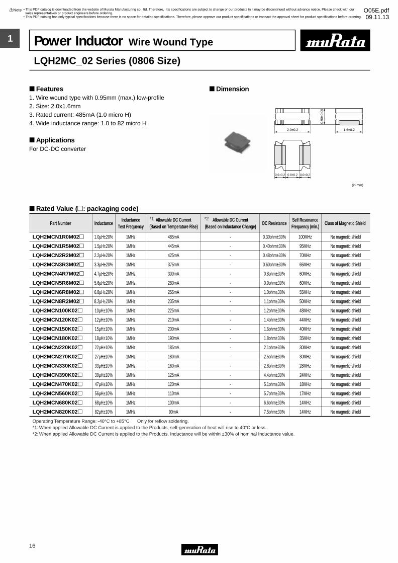
(in mm)
2.0±0.2
0.6±0.2 0.8±0.2 0.6±0.2
1.6±0.2
0.90
±0.0
5
Part Number InductanceInductance
Test FrequencyAllowable DC Current
(Based on Temperature Rise)Allowable DC Current
(Based on Inductance Change)DC Resistance
Self ResonanceFrequency (min.)
Class of Magnetic Shield
LQH2MCN1R0M02p 1.0µH±20% 1MHz 485mA - 0.30ohm±30% 100MHz No magnetic shield
LQH2MCN1R5M02p 1.5µH±20% 1MHz 445mA - 0.40ohm±30% 95MHz No magnetic shield
LQH2MCN2R2M02p 2.2µH±20% 1MHz 425mA - 0.48ohm±30% 70MHz No magnetic shield
LQH2MCN3R3M02p 3.3µH±20% 1MHz 375mA - 0.60ohm±30% 65MHz No magnetic shield
LQH2MCN4R7M02p 4.7µH±20% 1MHz 300mA - 0.8ohm±30% 60MHz No magnetic shield
LQH2MCN5R6M02p 5.6µH±20% 1MHz 280mA - 0.9ohm±30% 60MHz No magnetic shield
LQH2MCN6R8M02p 6.8µH±20% 1MHz 255mA - 1.0ohm±30% 55MHz No magnetic shield
LQH2MCN8R2M02p 8.2µH±20% 1MHz 235mA - 1.1ohm±30% 50MHz No magnetic shield
LQH2MCN100K02p 10µH±10% 1MHz 225mA - 1.2ohm±30% 48MHz No magnetic shield
LQH2MCN120K02p 12µH±10% 1MHz 210mA - 1.4ohm±30% 44MHz No magnetic shield
LQH2MCN150K02p 15µH±10% 1MHz 200mA - 1.6ohm±30% 40MHz No magnetic shield
LQH2MCN180K02p 18µH±10% 1MHz 190mA - 1.8ohm±30% 35MHz No magnetic shield
LQH2MCN220K02p 22µH±10% 1MHz 185mA - 2.1ohm±30% 30MHz No magnetic shield
LQH2MCN270K02p 27µH±10% 1MHz 180mA - 2.5ohm±30% 30MHz No magnetic shield
LQH2MCN330K02p 33µH±10% 1MHz 160mA - 2.8ohm±30% 28MHz No magnetic shield
LQH2MCN390K02p 39µH±10% 1MHz 125mA - 4.4ohm±30% 24MHz No magnetic shield
LQH2MCN470K02p 47µH±10% 1MHz 120mA - 5.1ohm±30% 18MHz No magnetic shield
LQH2MCN560K02p 56µH±10% 1MHz 110mA - 5.7ohm±30% 17MHz No magnetic shield
LQH2MCN680K02p 68µH±10% 1MHz 100mA - 6.6ohm±30% 14MHz No magnetic shield
LQH2MCN820K02p 82µH±10% 1MHz 90mA - 7.5ohm±30% 14MHz No magnetic shield
Operating Temperature Range: -40°C to +85°C Only for reflow soldering.
Power Inductor Wire Wound Type
LQH2MC_02 Series (0806 Size)
1. Wire wound type with 0.95mm (max.) low-profile2. Size: 2.0x1.6mm3. Rated current: 485mA (1.0 micro H)4. Wide inductance range: 1.0 to 82 micro H
ApplicationsFor DC-DC converter
Dimension Features
Rated Value (p: packaging code)
*1: When applied Allowable DC Current is applied to the Products, self-generation of heat will rise to 40°C or less.*2: When applied Allowable DC Current is applied to the Products, Inductance will be within ±30% of nominal Inductance value.
*1 *2
1
!Note • Please read rating and !CAUTION (for storage, operating, rating, soldering, mounting and handling) in this catalog to prevent smoking and/or burning, etc.• This catalog has only typical specifications because there is no space for detailed specifications. Therefore, please approve our product specifications or transact the approval sheet for product specifications before ordering.
17
• This PDF catalog is downloaded from the website of Murata Manufacturing co., ltd. Therefore, it’s specifications are subject to change or our products in it may be discontinued without advance notice. Please check with our sales representatives or product engineers before ordering.
• This PDF catalog has only typical specifications because there is no space for detailed specifications. Therefore, please approve our product specifications or transact the approval sheet for product specifications before ordering.
!Note O05E.pdf09.11.13
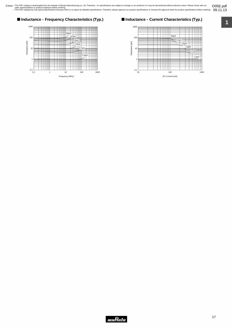
Indu
ctan
ce (
µH)
Frequency (MHz)
1000
100
10
1
0.10.1 1 10 1000100
82µH47µH
22µH
10µH
4.7µH
1.0µH
Inductance - Frequency Characteristics (Typ.)
Indu
ctan
ce (
µH)
DC Current (mA)
1000
100
10
1
0.110 1000100
82µH
47µH
22µH
10µH
4.7µH
1.0µH
Inductance - Current Characteristics (Typ.)
1
!Note • Please read rating and !CAUTION (for storage, operating, rating, soldering, mounting and handling) in this catalog to prevent smoking and/or burning, etc.• This catalog has only typical specifications because there is no space for detailed specifications. Therefore, please approve our product specifications or transact the approval sheet for product specifications before ordering.
18
• This PDF catalog is downloaded from the website of Murata Manufacturing co., ltd. Therefore, it’s specifications are subject to change or our products in it may be discontinued without advance notice. Please check with our sales representatives or product engineers before ordering.
• This PDF catalog has only typical specifications because there is no space for detailed specifications. Therefore, please approve our product specifications or transact the approval sheet for product specifications before ordering.
!Note O05E.pdf09.11.13
(in mm)
2.0±0.2
0.6±0.2 0.8±0.2 0.6±0.2
1.6±0.2
0.65
±0.0
5
Part Number InductanceInductance
Test FrequencyAllowable DC Current
(Based on Temperature Rise)Allowable DC Current
(Based on Inductance Change)DC Resistance
Self ResonanceFrequency (min.)
Class of Magnetic Shield
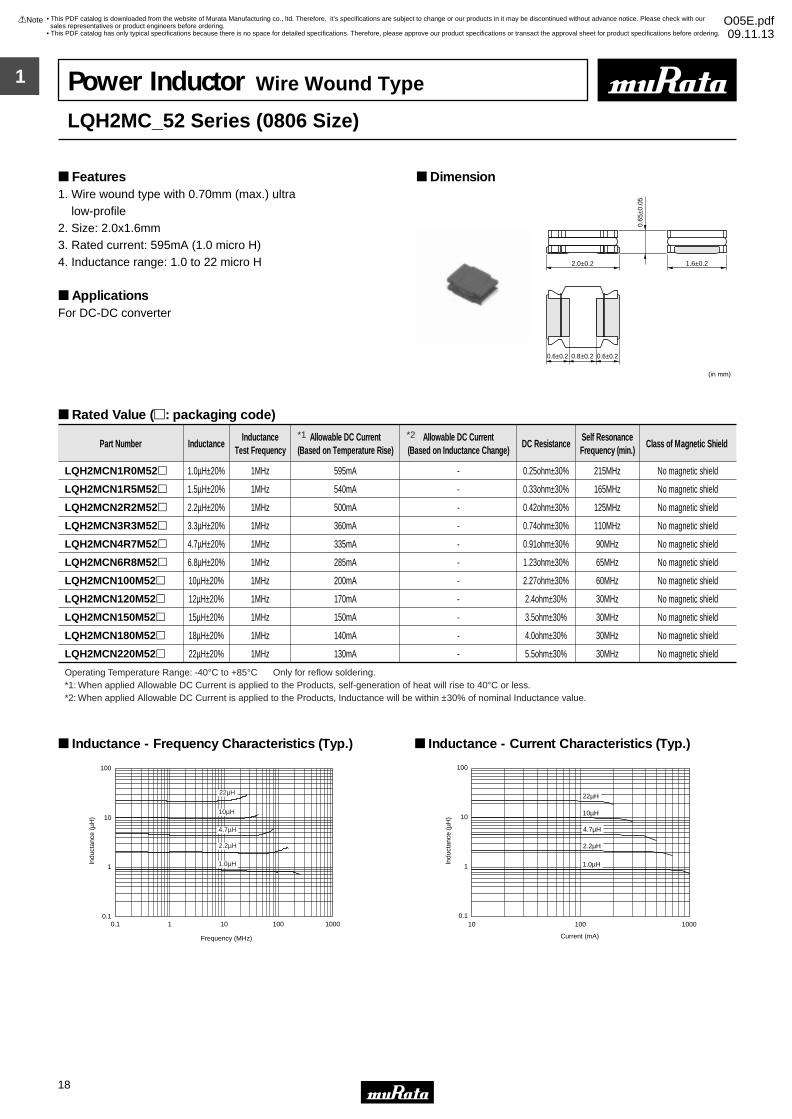
LQH2MCN1R0M52p 1.0µH±20% 1MHz 595mA - 0.25ohm±30% 215MHz No magnetic shield
LQH2MCN1R5M52p 1.5µH±20% 1MHz 540mA - 0.33ohm±30% 165MHz No magnetic shield
LQH2MCN2R2M52p 2.2µH±20% 1MHz 500mA - 0.42ohm±30% 125MHz No magnetic shield
LQH2MCN3R3M52p 3.3µH±20% 1MHz 360mA - 0.74ohm±30% 110MHz No magnetic shield
LQH2MCN4R7M52p 4.7µH±20% 1MHz 335mA - 0.91ohm±30% 90MHz No magnetic shield
LQH2MCN6R8M52p 6.8µH±20% 1MHz 285mA - 1.23ohm±30% 65MHz No magnetic shield
LQH2MCN100M52p 10µH±20% 1MHz 200mA - 2.27ohm±30% 60MHz No magnetic shield
LQH2MCN120M52p 12µH±20% 1MHz 170mA - 2.4ohm±30% 30MHz No magnetic shield
LQH2MCN150M52p 15µH±20% 1MHz 150mA - 3.5ohm±30% 30MHz No magnetic shield
LQH2MCN180M52p 18µH±20% 1MHz 140mA - 4.0ohm±30% 30MHz No magnetic shield
LQH2MCN220M52p 22µH±20% 1MHz 130mA - 5.5ohm±30% 30MHz No magnetic shield
Operating Temperature Range: -40°C to +85°C Only for reflow soldering.
Indu
ctan
ce (
µH)
Frequency (MHz)
0.1
1
10
100
0.1 1 10 100 1000
1.0µH
2.2µH
4.7µH
10µH
22µH
Inductance - Frequency Characteristics (Typ.)
Indu
ctan
ce (
µH)
0.1
1
10
100
10 100 1000
Current (mA)
1.0µH
2.2µH
4.7µH
10µH
22µH
Inductance - Current Characteristics (Typ.)
Power Inductor Wire Wound Type
LQH2MC_52 Series (0806 Size)
1. Wire wound type with 0.70mm (max.) ultra low-profile2. Size: 2.0x1.6mm3. Rated current: 595mA (1.0 micro H)4. Inductance range: 1.0 to 22 micro H
ApplicationsFor DC-DC converter
Dimension Features
Rated Value (p: packaging code)
*1: When applied Allowable DC Current is applied to the Products, self-generation of heat will rise to 40°C or less.*2: When applied Allowable DC Current is applied to the Products, Inductance will be within ±30% of nominal Inductance value.
*1 *2
1
!Note • Please read rating and !CAUTION (for storage, operating, rating, soldering, mounting and handling) in this catalog to prevent smoking and/or burning, etc.• This catalog has only typical specifications because there is no space for detailed specifications. Therefore, please approve our product specifications or transact the approval sheet for product specifications before ordering.
19
• This PDF catalog is downloaded from the website of Murata Manufacturing co., ltd. Therefore, it’s specifications are subject to change or our products in it may be discontinued without advance notice. Please check with our sales representatives or product engineers before ordering.
• This PDF catalog has only typical specifications because there is no space for detailed specifications. Therefore, please approve our product specifications or transact the approval sheet for product specifications before ordering.
!Note O05E.pdf09.11.13
2.7±0.2
3.0±0.2
0.9±0.2 0.9±0.2
1.2±0.2 (in mm)
3.0±
0.2
1.40
±0.1
Polarity Marking
Part Number InductanceInductance
Test FrequencyAllowable DC Current
(Based on Temperature Rise)Allowable DC Current
(Based on Inductance Change)DC Resistance
Self ResonanceFrequency (min.)
Class of Magnetic Shield
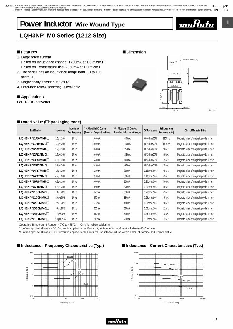
LQH3NPN1R0MM0p 1.0µH±20% 1MHz 2050mA 1400mA 0.044ohm±20% 130MHz Magnetic shield of magnetic powder in resin
LQH3NPN1R0NM0p 1.0µH±30% 1MHz 2050mA 1400mA 0.044ohm±20% 130MHz Magnetic shield of magnetic powder in resin
LQH3NPN2R2MM0p 2.2µH±20% 1MHz 1600mA 1250mA 0.073ohm±20% 90MHz Magnetic shield of magnetic powder in resin
LQH3NPN2R2NM0p 2.2µH±30% 1MHz 1600mA 1250mA 0.073ohm±20% 90MHz Magnetic shield of magnetic powder in resin
LQH3NPN3R3MM0p 3.3µH±20% 1MHz 1450mA 1000mA 0.092ohm±20% 75MHz Magnetic shield of magnetic powder in resin
LQH3NPN3R3NM0p 3.3µH±30% 1MHz 1450mA 1000mA 0.092ohm±20% 75MHz Magnetic shield of magnetic powder in resin
LQH3NPN4R7MM0p 4.7µH±20% 1MHz 1250mA 880mA 0.13ohm±20% 65MHz Magnetic shield of magnetic powder in resin
LQH3NPN4R7NM0p 4.7µH±30% 1MHz 1250mA 880mA 0.13ohm±20% 65MHz Magnetic shield of magnetic powder in resin
LQH3NPN6R8MM0p 6.8µH±20% 1MHz 1000mA 820mA 0.20ohm±20% 50MHz Magnetic shield of magnetic powder in resin
LQH3NPN6R8NM0p 6.8µH±30% 1MHz 1000mA 820mA 0.20ohm±20% 50MHz Magnetic shield of magnetic powder in resin
LQH3NPN100MM0p 10µH±20% 1MHz 870mA 550mA 0.26ohm±20% 45MHz Magnetic shield of magnetic powder in resin
LQH3NPN100NM0p 10µH±30% 1MHz 870mA 550mA 0.26ohm±20% 45MHz Magnetic shield of magnetic powder in resin
LQH3NPN220MM0p 22µH±20% 1MHz 650mA 410mA 0.51ohm±20% 28MHz Magnetic shield of magnetic powder in resin
LQH3NPN330MM0p 33µH±20% 1MHz 500mA 370mA 0.85ohm±20% 22MHz Magnetic shield of magnetic powder in resin
LQH3NPN470MM0p 47µH±20% 1MHz 410mA 310mA 1.25ohm±20% 18MHz Magnetic shield of magnetic powder in resin
LQH3NPN101MM0p 100µH±20% 1MHz 240mA 200mA 3.50ohm±20% 12MHz Magnetic shield of magnetic powder in resin
Operating Temperature Range: -40°C to +85°C Only for reflow soldering.
Indu
ctan
ce (
µH)
0.1
1
10
100
1000
0.1 1 10 100 1000
Frequency (MHz)
1.0µH
10µH
47µH
100µH
4.7µH
Inductance - Frequency Characteristics (Typ.)
Indu
ctan
ce (
µH)
0.1
1
10
100
1000
10 100 1000 10000
DC Current (mA)
1.0µH
47µH
10µH
4.7µH
100µH
Inductance - Current Characteristics (Typ.)
Power Inductor Wire Wound Type
LQH3NP_M0 Series (1212 Size)
1. Large rated current Based on Inductance change: 1400mA at 1.0 micro H Based on Temperature rise: 2050mA at 1.0 micro H 2. The series has an inductance range from 1.0 to 100 micro H.3. Magnetically shielded structure.4. Lead-free reflow soldering is available.
Applications For DC-DC converter
Dimension Features
Rated Value (p: packaging code)
*1: When applied Allowable DC Current is applied to the Products, self-generation of heat will rise to 40°C or less.*2: When applied Allowable DC Current is applied to the Products, Inductance will be within ±30% of nominal Inductance value.
*1 *2
1
!Note • Please read rating and !CAUTION (for storage, operating, rating, soldering, mounting and handling) in this catalog to prevent smoking and/or burning, etc.• This catalog has only typical specifications because there is no space for detailed specifications. Therefore, please approve our product specifications or transact the approval sheet for product specifications before ordering.
20
• This PDF catalog is downloaded from the website of Murata Manufacturing co., ltd. Therefore, it’s specifications are subject to change or our products in it may be discontinued without advance notice. Please check with our sales representatives or product engineers before ordering.
• This PDF catalog has only typical specifications because there is no space for detailed specifications. Therefore, please approve our product specifications or transact the approval sheet for product specifications before ordering.
!Note O05E.pdf09.11.13
3.0±0.2
0.9±0.2 0.9±0.2(in mm)
3.0±
0.2
1.1±
0.1
3.0±0.2
Polarity Marking
Part Number InductanceInductance
Test FrequencyAllowable DC Current
(Based on Temperature Rise)Allowable DC Current
(Based on Inductance Change)DC Resistance
Self ResonanceFrequency (min.)
Class of Magnetic Shield
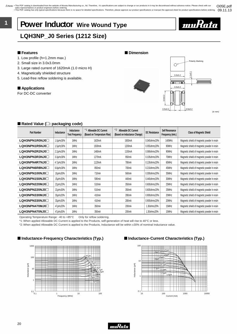
LQH3NPN1R0NJ0p 1.0µH±30% 1MHz 1620mA 1650mA 0.040ohm±20% 140MHz Magnetic shield of magnetic powder in resin
LQH3NPN1R5NJ0p 1.5µH±30% 1MHz 1500mA 1200mA 0.055ohm±20% 90MHz Magnetic shield of magnetic powder in resin
LQH3NPN2R2NJ0p 2.2µH±30% 1MHz 1460mA 1150mA 0.069ohm±20% 90MHz Magnetic shield of magnetic powder in resin
LQH3NPN3R3NJ0p 3.3µH±30% 1MHz 1270mA 950mA 0.105ohm±20% 70MHz Magnetic shield of magnetic powder in resin
LQH3NPN4R7NJ0p 4.7µH±30% 1MHz 1120mA 780mA 0.130ohm±20% 65MHz Magnetic shield of magnetic powder in resin
LQH3NPN6R8NJ0p 6.8µH±30% 1MHz 850mA 700mA 0.210ohm±20% 45MHz Magnetic shield of magnetic powder in resin
LQH3NPN100NJ0p 10µH±30% 1MHz 710mA 560mA 0.300ohm±20% 35MHz Magnetic shield of magnetic powder in resin
LQH3NPN150NJ0p 15µH±30% 1MHz 590mA 440mA 0.440ohm±20% 30MHz Magnetic shield of magnetic powder in resin
LQH3NPN220MJ0p 22µH±20% 1MHz 510mA 350mA 0.600ohm±20% 25MHz Magnetic shield of magnetic powder in resin
LQH3NPN220NJ0p 22µH±30% 1MHz 510mA 350mA 0.600ohm±20% 25MHz Magnetic shield of magnetic powder in resin
LQH3NPN330MJ0p 33µH±20% 1MHz 410mA 280mA 0.900ohm±20% 20MHz Magnetic shield of magnetic powder in resin
LQH3NPN330NJ0p 33µH±30% 1MHz 410mA 280mA 0.900ohm±20% 20MHz Magnetic shield of magnetic powder in resin
LQH3NPN470MJ0p 47µH±20% 1MHz 350mA 200mA 1.30ohm±20% 15MHz Magnetic shield of magnetic powder in resin
LQH3NPN470NJ0p 47µH±30% 1MHz 350mA 200mA 1.30ohm±20% 15MHz Magnetic shield of magnetic powder in resin
Operating Temperature Range: -40 to +85°C Only for reflow soldering.
1.0µH
1.5µH2.2µH
3.3µH4.7µH
6.8µH10µH
15µH22µH
33µH47µH
0.1
1
10
100
1000
0.1 1 10 100Frequency (MHz)
Indu
ctan
ce (
µH)
Inductance-Frequency Characteristics (Typ.)
1.0µH1.5µH
2.2µH3.3µH
4.7µH
6.8µH10µH
15µH22µH
33µH47µH
0.1
1
10
100
10 100 1000 10000Current (mA)
Indu
ctan
ce (
µH)
Inductance-Current Characteristics (Typ.)
Power Inductor Wire Wound Type
LQH3NP_J0 Series (1212 Size)
1. Low profile (h=1.2mm max.) 2. Small size in 3.0x3.0mm3. Large rated current of 1620mA (1.0 micro H)4. Magnetically shielded structure5. Lead-free reflow soldering is available.
ApplicationsFor DC-DC converter
Dimension Features
Rated Value (p: packaging code)
*1: When applied Allowable DC Current is applied to the Products, self-generation of heat will rise to 40°C or less.*2: When applied Allowable DC Current is applied to the Products, Inductance will be within ±30% of nominal Inductance value.
*1 *2
1
!Note • Please read rating and !CAUTION (for storage, operating, rating, soldering, mounting and handling) in this catalog to prevent smoking and/or burning, etc.• This catalog has only typical specifications because there is no space for detailed specifications. Therefore, please approve our product specifications or transact the approval sheet for product specifications before ordering.
21
• This PDF catalog is downloaded from the website of Murata Manufacturing co., ltd. Therefore, it’s specifications are subject to change or our products in it may be discontinued without advance notice. Please check with our sales representatives or product engineers before ordering.
• This PDF catalog has only typical specifications because there is no space for detailed specifications. Therefore, please approve our product specifications or transact the approval sheet for product specifications before ordering.
!Note O05E.pdf09.11.13
2.7±0.2
3.0±0.2
0.9±0.2 0.9±0.2
1.2±0.2 (in mm)
3.0±
0.2
0.90
±0.1
Polarity Marking
Part Number InductanceInductance
Test FrequencyAllowable DC Current
(Based on Temperature Rise)Allowable DC Current
(Based on Inductance Change)DC Resistance
Self ResonanceFrequency (min.)
Class of Magnetic Shield
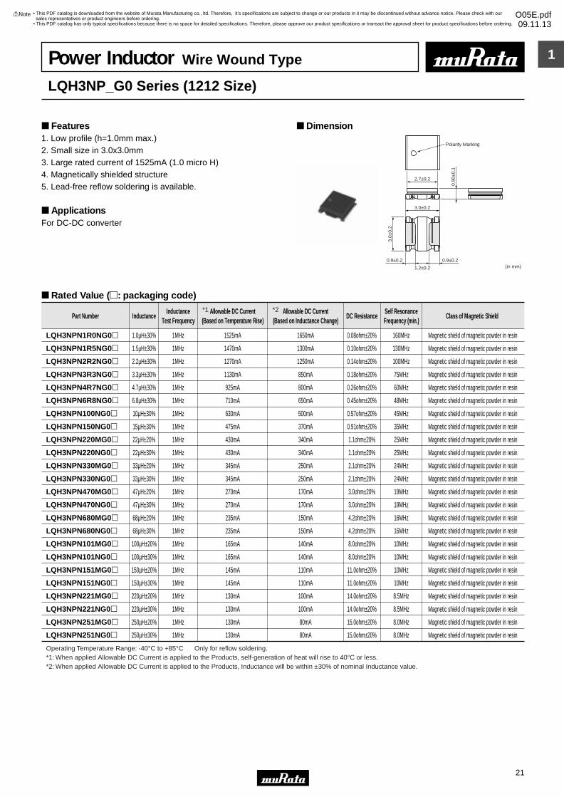
LQH3NPN1R0NG0p 1.0µH±30% 1MHz 1525mA 1650mA 0.08ohm±20% 160MHz Magnetic shield of magnetic powder in resin
LQH3NPN1R5NG0p 1.5µH±30% 1MHz 1470mA 1300mA 0.10ohm±20% 130MHz Magnetic shield of magnetic powder in resin
LQH3NPN2R2NG0p 2.2µH±30% 1MHz 1270mA 1250mA 0.14ohm±20% 100MHz Magnetic shield of magnetic powder in resin
LQH3NPN3R3NG0p 3.3µH±30% 1MHz 1130mA 850mA 0.18ohm±20% 75MHz Magnetic shield of magnetic powder in resin
LQH3NPN4R7NG0p 4.7µH±30% 1MHz 925mA 800mA 0.26ohm±20% 60MHz Magnetic shield of magnetic powder in resin
LQH3NPN6R8NG0p 6.8µH±30% 1MHz 710mA 650mA 0.45ohm±20% 48MHz Magnetic shield of magnetic powder in resin
LQH3NPN100NG0p 10µH±30% 1MHz 630mA 500mA 0.57ohm±20% 45MHz Magnetic shield of magnetic powder in resin
LQH3NPN150NG0p 15µH±30% 1MHz 475mA 370mA 0.91ohm±20% 35MHz Magnetic shield of magnetic powder in resin
LQH3NPN220MG0p 22µH±20% 1MHz 430mA 340mA 1.1ohm±20% 25MHz Magnetic shield of magnetic powder in resin
LQH3NPN220NG0p 22µH±30% 1MHz 430mA 340mA 1.1ohm±20% 25MHz Magnetic shield of magnetic powder in resin
LQH3NPN330MG0p 33µH±20% 1MHz 345mA 250mA 2.1ohm±20% 24MHz Magnetic shield of magnetic powder in resin
LQH3NPN330NG0p 33µH±30% 1MHz 345mA 250mA 2.1ohm±20% 24MHz Magnetic shield of magnetic powder in resin
LQH3NPN470MG0p 47µH±20% 1MHz 270mA 170mA 3.0ohm±20% 19MHz Magnetic shield of magnetic powder in resin
LQH3NPN470NG0p 47µH±30% 1MHz 270mA 170mA 3.0ohm±20% 19MHz Magnetic shield of magnetic powder in resin
LQH3NPN680MG0p 68µH±20% 1MHz 235mA 150mA 4.2ohm±20% 16MHz Magnetic shield of magnetic powder in resin
LQH3NPN680NG0p 68µH±30% 1MHz 235mA 150mA 4.2ohm±20% 16MHz Magnetic shield of magnetic powder in resin
LQH3NPN101MG0p 100µH±20% 1MHz 165mA 140mA 8.0ohm±20% 10MHz Magnetic shield of magnetic powder in resin
LQH3NPN101NG0p 100µH±30% 1MHz 165mA 140mA 8.0ohm±20% 10MHz Magnetic shield of magnetic powder in resin
LQH3NPN151MG0p 150µH±20% 1MHz 145mA 110mA 11.0ohm±20% 10MHz Magnetic shield of magnetic powder in resin
LQH3NPN151NG0p 150µH±30% 1MHz 145mA 110mA 11.0ohm±20% 10MHz Magnetic shield of magnetic powder in resin
LQH3NPN221MG0p 220µH±20% 1MHz 130mA 100mA 14.0ohm±20% 8.5MHz Magnetic shield of magnetic powder in resin
LQH3NPN221NG0p 220µH±30% 1MHz 130mA 100mA 14.0ohm±20% 8.5MHz Magnetic shield of magnetic powder in resin
LQH3NPN251MG0p 250µH±20% 1MHz 130mA 80mA 15.0ohm±20% 8.0MHz Magnetic shield of magnetic powder in resin
LQH3NPN251NG0p 250µH±30% 1MHz 130mA 80mA 15.0ohm±20% 8.0MHz Magnetic shield of magnetic powder in resin
Operating Temperature Range: -40°C to +85°C Only for reflow soldering.
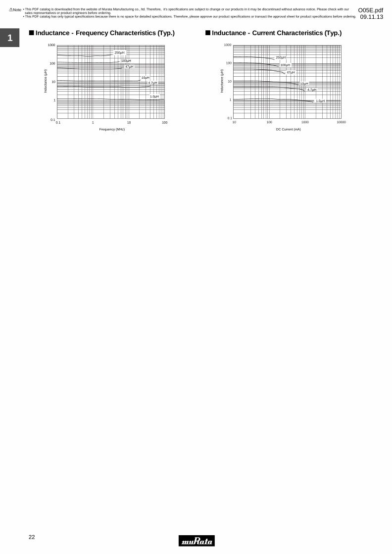
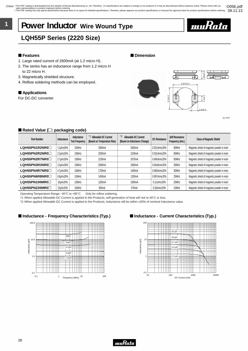
Power Inductor Wire Wound Type
LQH3NP_G0 Series (1212 Size)
1. Low profile (h=1.0mm max.) 2. Small size in 3.0x3.0mm3. Large rated current of 1525mA (1.0 micro H)4. Magnetically shielded structure5. Lead-free reflow soldering is available.
ApplicationsFor DC-DC converter
Dimension Features
Rated Value (p: packaging code)
*1: When applied Allowable DC Current is applied to the Products, self-generation of heat will rise to 40°C or less.*2: When applied Allowable DC Current is applied to the Products, Inductance will be within ±30% of nominal Inductance value.
*1 *2
1
!Note • Please read rating and !CAUTION (for storage, operating, rating, soldering, mounting and handling) in this catalog to prevent smoking and/or burning, etc.• This catalog has only typical specifications because there is no space for detailed specifications. Therefore, please approve our product specifications or transact the approval sheet for product specifications before ordering.
22
• This PDF catalog is downloaded from the website of Murata Manufacturing co., ltd. Therefore, it’s specifications are subject to change or our products in it may be discontinued without advance notice. Please check with our sales representatives or product engineers before ordering.
• This PDF catalog has only typical specifications because there is no space for detailed specifications. Therefore, please approve our product specifications or transact the approval sheet for product specifications before ordering.
!Note O05E.pdf09.11.13
Frequency (MHz)
Indu
ctan
ce (
µH)
0.1
1
10
100
1000
0.1 1 10 100
1.0µH
4.7µH
47µH
100µH
250µH
10µH
Inductance - Frequency Characteristics (Typ.)
DC Current (mA)
Indu
ctan
ce (
µH)
0.1
1
10
100
1000
10 100 1000 10000
1.0µH
4.7µH
10µH
47µH
100µH
250µH
Inductance - Current Characteristics (Typ.)
1
!Note • Please read rating and !CAUTION (for storage, operating, rating, soldering, mounting and handling) in this catalog to prevent smoking and/or burning, etc.• This catalog has only typical specifications because there is no space for detailed specifications. Therefore, please approve our product specifications or transact the approval sheet for product specifications before ordering.
23
• This PDF catalog is downloaded from the website of Murata Manufacturing co., ltd. Therefore, it’s specifications are subject to change or our products in it may be discontinued without advance notice. Please check with our sales representatives or product engineers before ordering.
• This PDF catalog has only typical specifications because there is no space for detailed specifications. Therefore, please approve our product specifications or transact the approval sheet for product specifications before ordering.
!Note O05E.pdf09.11.13
2.7±0.2
(in mm)
3.2±0.3
2.5±0.2
2.5±0.2
A: 2.8 max.
AA
1.3±0.2
0.9±0.30.9±0.3
1.55
±0.1
5
Part Number InductanceInductance
Test FrequencyAllowable DC Current
(Based on Temperature Rise)Allowable DC Current
(Based on Inductance Change)DC Resistance
Self ResonanceFrequency (min.)
Class of Magnetic Shield
LQH32PNR47NN0p 0.47µH±30% 1MHz 2550mA 3400mA 0.03ohm±20% 100MHz Magnetic shield of magnetic powder in resin
LQH32PN1R0NN0p 1.0µH±30% 1MHz 2050mA 2300mA 0.045ohm±20% 100MHz Magnetic shield of magnetic powder in resin
LQH32PN1R5NN0p 1.5µH±30% 1MHz 1750mA 1750mA 0.057ohm±20% 70MHz Magnetic shield of magnetic powder in resin
LQH32PN2R2NN0p 2.2µH±30% 1MHz 1600mA 1550mA 0.076ohm±20% 70MHz Magnetic shield of magnetic powder in resin
LQH32PN3R3NN0p 3.3µH±30% 1MHz 1200mA 1250mA 0.12ohm±20% 50MHz Magnetic shield of magnetic powder in resin
LQH32PN4R7NN0p 4.7µH±30% 1MHz 1000mA 1000mA 0.18ohm±20% 40MHz Magnetic shield of magnetic powder in resin
LQH32PN6R8NN0p 6.8µH±30% 1MHz 850mA 850mA 0.24ohm±20% 40MHz Magnetic shield of magnetic powder in resin
LQH32PN100MN0p 10µH±20% 1MHz 700mA 750mA 0.38ohm±20% 30MHz Magnetic shield of magnetic powder in resin
LQH32PN220MN0p 22µH±20% 1MHz 450mA 500mA 0.81ohm±20% 20MHz Magnetic shield of magnetic powder in resin
Operating Temperature Range: -40°C to +85°C Only for reflow soldering.
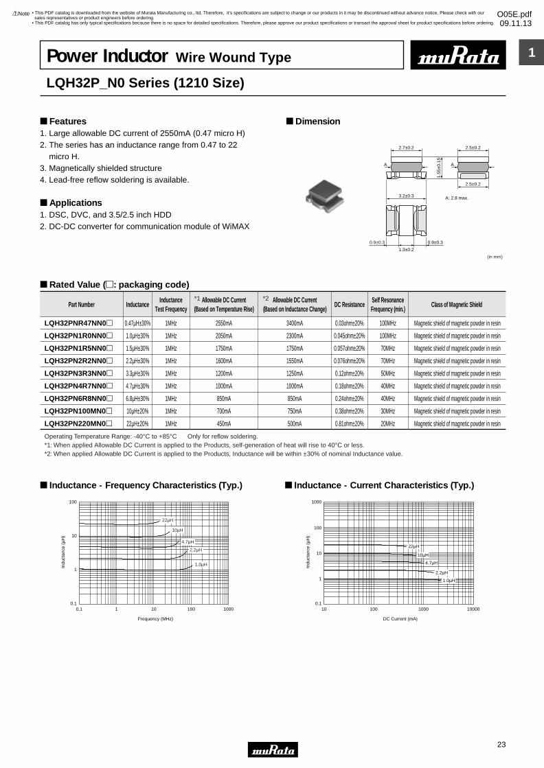
Indu
ctan
ce (
µH)
Frequency (MHz)
100
10
1
0.10.1 1 10 1000100
22µH
10µH
4.7µH
2.2µH
1.0µH
Inductance - Frequency Characteristics (Typ.)
Indu
ctan
ce (
µH)
1000
100
10
1
0.1
DC Current (mA)
10 100 1000 10000
22µH
10µH
4.7µH
2.2µH
1.0µH
Inductance - Current Characteristics (Typ.)
Power Inductor Wire Wound Type
LQH32P_N0 Series (1210 Size)
1. Large allowable DC current of 2550mA (0.47 micro H)2. The series has an inductance range from 0.47 to 22 micro H.3. Magnetically shielded structure4. Lead-free reflow soldering is available.
Applications1. DSC, DVC, and 3.5/2.5 inch HDD2. DC-DC converter for communication module of WiMAX
Dimension Features
Rated Value (p: packaging code)
*1: When applied Allowable DC Current is applied to the Products, self-generation of heat will rise to 40°C or less.*2: When applied Allowable DC Current is applied to the Products, Inductance will be within ±30% of nominal Inductance value.
*1 *2
1
!Note • Please read rating and !CAUTION (for storage, operating, rating, soldering, mounting and handling) in this catalog to prevent smoking and/or burning, etc.• This catalog has only typical specifications because there is no space for detailed specifications. Therefore, please approve our product specifications or transact the approval sheet for product specifications before ordering.
24
• This PDF catalog is downloaded from the website of Murata Manufacturing co., ltd. Therefore, it’s specifications are subject to change or our products in it may be discontinued without advance notice. Please check with our sales representatives or product engineers before ordering.
• This PDF catalog has only typical specifications because there is no space for detailed specifications. Therefore, please approve our product specifications or transact the approval sheet for product specifications before ordering.
!Note O05E.pdf09.11.13
4.0±0.2
1.65
±0.1
5
4.0±0.2
1.2±0.2 1.2±0.21.0 min.
3.7±0.2
2.4 min.
0.35
min
.
3.5±
0.2
(in mm)
Part Number InductanceInductance
Test FrequencyAllowable DC Current
(Based on Temperature Rise)Allowable DC Current
(Based on Inductance Change)DC Resistance
Self ResonanceFrequency (min.)
Class of Magnetic Shield
LQH44PN1R0NP0p 1.0µH±30% 1MHz 2450mA 2950mA 0.030ohm±20% 90MHz Magnetic shield of magnetic powder in resin
LQH44PN2R2MP0p 2.2µH±20% 1MHz 1800mA 2500mA 0.049ohm±20% 70MHz Magnetic shield of magnetic powder in resin
LQH44PN3R3MP0p 3.3µH±20% 1MHz 1770mA 2100mA 0.065ohm±20% 50MHz Magnetic shield of magnetic powder in resin
LQH44PN4R7MP0p 4.7µH±20% 1MHz 1700mA 1700mA 0.080ohm±20% 40MHz Magnetic shield of magnetic powder in resin
LQH44PN6R8MP0p 6.8µH±20% 1MHz 1340mA 1400mA 0.12ohm±20% 35MHz Magnetic shield of magnetic powder in resin
LQH44PN100MP0p 10µH±20% 1MHz 1170mA 1150mA 0.16ohm±20% 25MHz Magnetic shield of magnetic powder in resin
LQH44PN220MP0p 22µH±20% 1MHz 790mA 800mA 0.37ohm±20% 17MHz Magnetic shield of magnetic powder in resin
Operating Temperature Range: -40 to +85°C Only for reflow soldering.
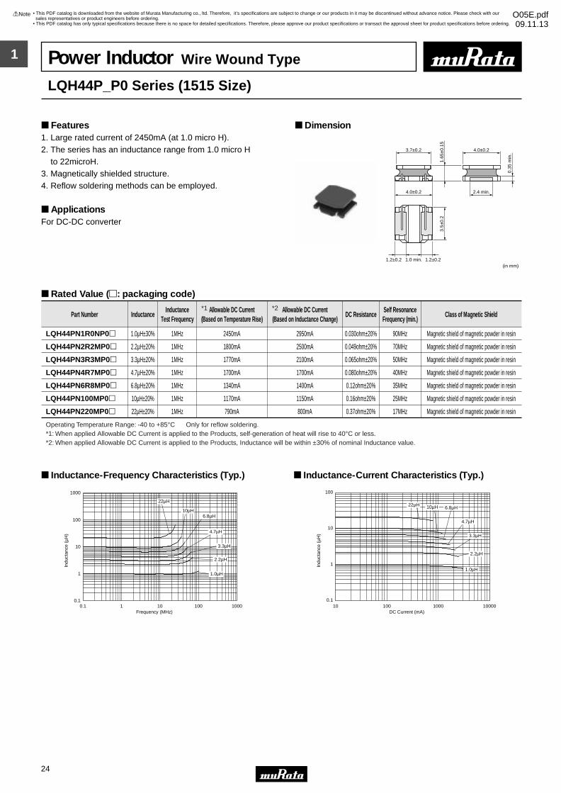
0.1
1
10
100
1000
0.1 1 10 100 1000Frequency (MHz)
Indu
ctan
ce (
µH)
1.0µH
2.2µH
3.3µH
4.7µH
6.8µH10µH
22µH
Inductance-Frequency Characteristics (Typ.)
1.0µH
2.2µH
3.3µH
4.7µH
6.8µH10µH22µH
0.1
1
10
100
10 100 1000 10000DC Current (mA)
Indu
ctan
ce (
µH)
Inductance-Current Characteristics (Typ.)
Power Inductor Wire Wound Type
LQH44P_P0 Series (1515 Size)
1. Large rated current of 2450mA (at 1.0 micro H).2. The series has an inductance range from 1.0 micro H to 22microH.3. Magnetically shielded structure.4. Reflow soldering methods can be employed.
ApplicationsFor DC-DC converter
Dimension Features
Rated Value (p: packaging code)
*1: When applied Allowable DC Current is applied to the Products, self-generation of heat will rise to 40°C or less.*2: When applied Allowable DC Current is applied to the Products, Inductance will be within ±30% of nominal Inductance value.
*1 *2

1
!Note • Please read rating and !CAUTION (for storage, operating, rating, soldering, mounting and handling) in this catalog to prevent smoking and/or burning, etc.• This catalog has only typical specifications because there is no space for detailed specifications. Therefore, please approve our product specifications or transact the approval sheet for product specifications before ordering.
25
• This PDF catalog is downloaded from the website of Murata Manufacturing co., ltd. Therefore, it’s specifications are subject to change or our products in it may be discontinued without advance notice. Please check with our sales representatives or product engineers before ordering.
• This PDF catalog has only typical specifications because there is no space for detailed specifications. Therefore, please approve our product specifications or transact the approval sheet for product specifications before ordering.
!Note O05E.pdf09.11.13
4.0±0.2
1.1±0.2 1.1±0.2
4.0±
0.2
1.1±
0.1
(0.1
2)
(in mm)
Part Number InductanceInductance
Test FrequencyAllowable DC Current
(Based on Temperature Rise)Allowable DC Current
(Based on Inductance Change)DC Resistance
Self ResonanceFrequency (min.)
Class of Magnetic Shield
LQH44PN1R0NJ0p 1.0µH±30% 1MHz 1530mA 2000mA 0.048ohm±20% 120MHz Magnetic shield of magnetic powder in resin
LQH44PN1R5MJ0p 1.5µH±20% 1MHz 1380mA 1600mA 0.061ohm±20% 90MHz Magnetic shield of magnetic powder in resin
LQH44PN2R2MJ0p 2.2µH±20% 1MHz 1230mA 1320mA 0.074ohm±20% 68MHz Magnetic shield of magnetic powder in resin
LQH44PN3R3MJ0p 3.3µH±20% 1MHz 1000mA 900mA 0.088ohm±20% 55MHz Magnetic shield of magnetic powder in resin
LQH44PN4R7MJ0p 4.7µH±20% 1MHz 980mA 840mA 0.117ohm±20% 50MHz Magnetic shield of magnetic powder in resin
LQH44PN6R8MJ0p 6.8µH±20% 1MHz 860mA 720mA 0.143ohm±20% 38MHz Magnetic shield of magnetic powder in resin
LQH44PN100MJ0p 10µH±20% 1MHz 790mA 560mA 0.207ohm±20% 30MHz Magnetic shield of magnetic powder in resin
LQH44PN150MJ0p 15µH±20% 1MHz 610mA 430mA 0.385ohm±20% 25MHz Magnetic shield of magnetic powder in resin
LQH44PN220MJ0p 22µH±20% 1MHz 550mA 400mA 0.480ohm±20% 18MHz Magnetic shield of magnetic powder in resin
LQH44PN330MJ0p 33µH±20% 1MHz 430mA 360mA 0.740ohm±20% 15MHz Magnetic shield of magnetic powder in resin
LQH44PN470MJ0p 47µH±20% 1MHz 380mA 300mA 1.014ohm±20% 13MHz Magnetic shield of magnetic powder in resin
Operating Temperature Range: -40 to +85°C Only for reflow soldering.
0.1
1
10
100
1000
0.1 1 10 100 1000Frequency (MHz)
Indu
ctan
ce (
µH)
1.0µH
2.2µH1.5µH
3.3µH4.7µH
6.8µH10µH
15µH22µH
33µH47µH
Inductance-Frequency Characteristics (Typ.)
0.1
1
10
100
10 100 1000 10000DC Current (mA)
Indu
ctan
ce (
µH)
1.0µH1.5µH2.2µH3.3µH4.7µH6.8µH10µH15µH22µH33µH47µH
Inductance-Current Characteristics (Typ.)
Power Inductor Wire Wound Type
LQH44P_J0 Series (1515 Size)
1. Large rated current of 1530mA (at 1.0 micro H).2. The series has an inductance range from 1.0 micro H to 47 micro H.3. Magnetically shielded structure.4. Reflow soldering methods can be employed.
ApplicationsFor DC-DC converter
Dimension Features
Rated Value (p: packaging code)
*1: When applied Allowable DC Current is applied to the Products, self-generation of heat will rise to 40°C or less.*2: When applied Allowable DC Current is applied to the Products, Inductance will be within ±30% of nominal Inductance value.
*1 *2
1
!Note • Please read rating and !CAUTION (for storage, operating, rating, soldering, mounting and handling) in this catalog to prevent smoking and/or burning, etc.• This catalog has only typical specifications because there is no space for detailed specifications. Therefore, please approve our product specifications or transact the approval sheet for product specifications before ordering.
26
• This PDF catalog is downloaded from the website of Murata Manufacturing co., ltd. Therefore, it’s specifications are subject to change or our products in it may be discontinued without advance notice. Please check with our sales representatives or product engineers before ordering.
• This PDF catalog has only typical specifications because there is no space for detailed specifications. Therefore, please approve our product specifications or transact the approval sheet for product specifications before ordering.
!Note O05E.pdf09.11.13
5.87±0.2
5.2±
0.2
1.2±
0.2
1.6±0.2
1.85
±0.1
5
(in mm)
Part Number InductanceInductance
Test FrequencyAllowable DC Current
(Based on Temperature Rise)Allowable DC Current
(Based on Inductance Change)DC Resistance
Self ResonanceFrequency (min.)
Class of Magnetic Shield
LQH55PN1R2NR0p 1.2µH±30% 100kHz 2900mA 2600mA 0.021ohm±20% 80MHz Magnetic shield of magnetic powder in resin
LQH55PN2R2NR0p 2.2µH±30% 100kHz 2500mA 2100mA 0.031ohm±20% 60MHz Magnetic shield of magnetic powder in resin
LQH55PN2R7NR0p 2.7µH±30% 100kHz 2150mA 2070mA 0.040ohm±20% 50MHz Magnetic shield of magnetic powder in resin
LQH55PN3R3NR0p 3.3µH±30% 100kHz 2000mA 2000mA 0.044ohm±20% 35MHz Magnetic shield of magnetic powder in resin
LQH55PN4R7NR0p 4.7µH±30% 100kHz 1750mA 1400mA 0.060ohm±20% 30MHz Magnetic shield of magnetic powder in resin
LQH55PN6R8NR0p 6.8µH±30% 100kHz 1450mA 1200mA 0.087ohm±20% 25MHz Magnetic shield of magnetic powder in resin
LQH55PN100MR0p 10µH±20% 100kHz 1250mA 1000mA 0.11ohm±20% 20MHz Magnetic shield of magnetic powder in resin
LQH55PN220MR0p 22µH±20% 100kHz 850mA 670mA 0.26ohm±20% 10MHz Magnetic shield of magnetic powder in resin
Operating Temperature Range: -40°C to +85°C Only for reflow soldering.
Indu
ctan
ce (
µH)
Frequency (MHz)
0.1
1.0
10.0
100.0
0.1 1 10 100
22µH
1.2µH
2.2µH
4.7µH
10µH
Inductance - Frequency Characteristics (Typ.)
0.1
100
10
1
Indu
ctan
ce (
µH)
10 100 1000 10000DC Current (mA)
22 µH
10 µH
4.7 µH
2.2 µH
1.2 µH
Inductance - Current Characteristics (Typ.)
Power Inductor Wire Wound Type
LQH55P Series (2220 Size)
1. Large rated current of 2600mA (at 1.2 micro H).2. The series has an inductance range from 1.2 micro H to 22 micro H.3. Magnetically shielded structure.4. Reflow soldering methods can be employed.
ApplicationsFor DC-DC converter
Dimension Features
Rated Value (p: packaging code)
*1: When applied Allowable DC Current is applied to the Products, self-generation of heat will rise to 40°C or less.*2: When applied Allowable DC Current is applied to the Products, Inductance will be within ±30% of nominal Inductance value.
*1 *2
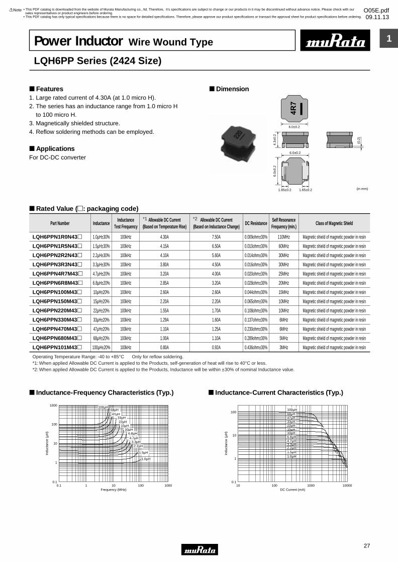
1
!Note • Please read rating and !CAUTION (for storage, operating, rating, soldering, mounting and handling) in this catalog to prevent smoking and/or burning, etc.• This catalog has only typical specifications because there is no space for detailed specifications. Therefore, please approve our product specifications or transact the approval sheet for product specifications before ordering.
27
• This PDF catalog is downloaded from the website of Murata Manufacturing co., ltd. Therefore, it’s specifications are subject to change or our products in it may be discontinued without advance notice. Please check with our sales representatives or product engineers before ordering.
• This PDF catalog has only typical specifications because there is no space for detailed specifications. Therefore, please approve our product specifications or transact the approval sheet for product specifications before ordering.
!Note O05E.pdf09.11.13
6.0±0.2
6.0±0.2
1.65±0.2 1.65±0.2
6.0±
0.2
4.3±
0.2
(0.2
)
(in mm)
Part Number InductanceInductance
Test FrequencyAllowable DC Current
(Based on Temperature Rise)Allowable DC Current
(Based on Inductance Change)DC Resistance
Self ResonanceFrequency (min.)
Class of Magnetic Shield
LQH6PPN1R0N43p 1.0µH±30% 100kHz 4.30A 7.50A 0.009ohm±30% 110MHz Magnetic shield of magnetic powder in resin
LQH6PPN1R5N43p 1.5µH±30% 100kHz 4.15A 6.50A 0.010ohm±30% 60MHz Magnetic shield of magnetic powder in resin
LQH6PPN2R2N43p 2.2µH±30% 100kHz 4.10A 5.60A 0.014ohm±30% 30MHz Magnetic shield of magnetic powder in resin
LQH6PPN3R3N43p 3.3µH±30% 100kHz 3.80A 4.50A 0.016ohm±30% 30MHz Magnetic shield of magnetic powder in resin
LQH6PPN4R7M43p 4.7µH±20% 100kHz 3.20A 4.00A 0.020ohm±30% 25MHz Magnetic shield of magnetic powder in resin
LQH6PPN6R8M43p 6.8µH±20% 100kHz 2.85A 3.20A 0.028ohm±30% 20MHz Magnetic shield of magnetic powder in resin
LQH6PPN100M43p 10µH±20% 100kHz 2.60A 2.60A 0.044ohm±30% 15MHz Magnetic shield of magnetic powder in resin
LQH6PPN150M43p 15µH±20% 100kHz 2.20A 2.20A 0.065ohm±30% 10MHz Magnetic shield of magnetic powder in resin
LQH6PPN220M43p 22µH±20% 100kHz 1.55A 1.70A 0.108ohm±30% 10MHz Magnetic shield of magnetic powder in resin
LQH6PPN330M43p 33µH±20% 100kHz 1.29A 1.60A 0.137ohm±30% 6MHz Magnetic shield of magnetic powder in resin
LQH6PPN470M43p 47µH±20% 100kHz 1.10A 1.25A 0.230ohm±30% 6MHz Magnetic shield of magnetic powder in resin
LQH6PPN680M43p 68µH±20% 100kHz 1.00A 1.10A 0.289ohm±30% 5MHz Magnetic shield of magnetic powder in resin
LQH6PPN101M43p 100µH±20% 100kHz 0.80A 0.92A 0.436ohm±30% 3MHz Magnetic shield of magnetic powder in resin
Operating Temperature Range: -40 to +85°C Only for reflow soldering.
0.1
1
10
100
1000
0.1 1 10 100 1000Frequency (MHz)
Indu
ctan
ce (
µH)
1.0µH
1.5µH
2.2µH3.3µH
4.7µH6.8µH
10µH15µH
22µH33µH
47µH68µH
100µH
Inductance-Frequency Characteristics (Typ.)
0.1
1
10
100
10 100 1000 10000DC Current (mA)
Indu
ctan
ce (
µH)
1.0µH1.5µH2.2µH3.3µH4.7µH6.8µH10µH15µH22µH33µH47µH68µH100µH
Inductance-Current Characteristics (Typ.)
Power Inductor Wire Wound Type
LQH6PP Series (2424 Size)
1. Large rated current of 4.30A (at 1.0 micro H).2. The series has an inductance range from 1.0 micro H to 100 micro H.3. Magnetically shielded structure.4. Reflow soldering methods can be employed.
ApplicationsFor DC-DC converter
Dimension Features
Rated Value (p: packaging code)
*1: When applied Allowable DC Current is applied to the Products, self-generation of heat will rise to 40°C or less.*2: When applied Allowable DC Current is applied to the Products, Inductance will be within ±30% of nominal Inductance value.
*1 *2
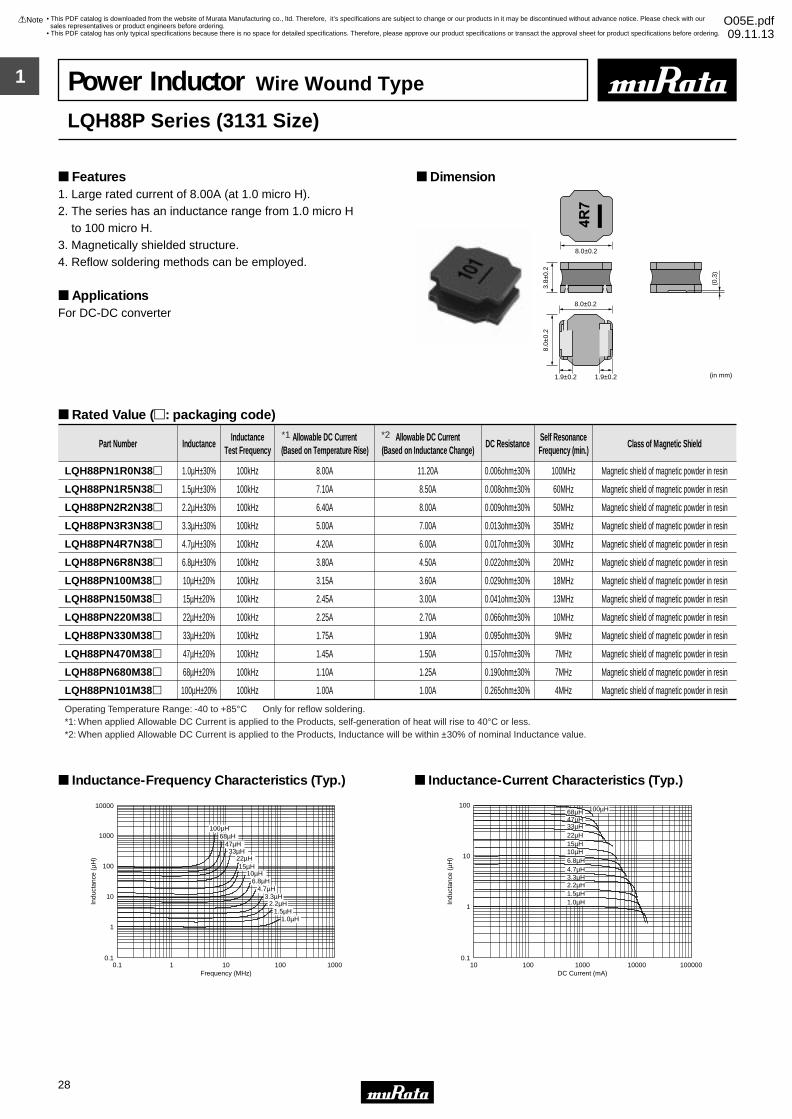
1
!Note • Please read rating and !CAUTION (for storage, operating, rating, soldering, mounting and handling) in this catalog to prevent smoking and/or burning, etc.• This catalog has only typical specifications because there is no space for detailed specifications. Therefore, please approve our product specifications or transact the approval sheet for product specifications before ordering.
28
• This PDF catalog is downloaded from the website of Murata Manufacturing co., ltd. Therefore, it’s specifications are subject to change or our products in it may be discontinued without advance notice. Please check with our sales representatives or product engineers before ordering.
• This PDF catalog has only typical specifications because there is no space for detailed specifications. Therefore, please approve our product specifications or transact the approval sheet for product specifications before ordering.
!Note O05E.pdf09.11.13
8.0±0.2
8.0±0.2
1.9±0.2 1.9±0.2
8.0±
0.2
3.8±
0.2
(0.3
)
(in mm)
Part Number InductanceInductance
Test FrequencyAllowable DC Current
(Based on Temperature Rise)Allowable DC Current
(Based on Inductance Change)DC Resistance
Self ResonanceFrequency (min.)
Class of Magnetic Shield
LQH88PN1R0N38p 1.0µH±30% 100kHz 8.00A 11.20A 0.006ohm±30% 100MHz Magnetic shield of magnetic powder in resin
LQH88PN1R5N38p 1.5µH±30% 100kHz 7.10A 8.50A 0.008ohm±30% 60MHz Magnetic shield of magnetic powder in resin
LQH88PN2R2N38p 2.2µH±30% 100kHz 6.40A 8.00A 0.009ohm±30% 50MHz Magnetic shield of magnetic powder in resin
LQH88PN3R3N38p 3.3µH±30% 100kHz 5.00A 7.00A 0.013ohm±30% 35MHz Magnetic shield of magnetic powder in resin
LQH88PN4R7N38p 4.7µH±30% 100kHz 4.20A 6.00A 0.017ohm±30% 30MHz Magnetic shield of magnetic powder in resin
LQH88PN6R8N38p 6.8µH±30% 100kHz 3.80A 4.50A 0.022ohm±30% 20MHz Magnetic shield of magnetic powder in resin
LQH88PN100M38p 10µH±20% 100kHz 3.15A 3.60A 0.029ohm±30% 18MHz Magnetic shield of magnetic powder in resin
LQH88PN150M38p 15µH±20% 100kHz 2.45A 3.00A 0.041ohm±30% 13MHz Magnetic shield of magnetic powder in resin
LQH88PN220M38p 22µH±20% 100kHz 2.25A 2.70A 0.066ohm±30% 10MHz Magnetic shield of magnetic powder in resin
LQH88PN330M38p 33µH±20% 100kHz 1.75A 1.90A 0.095ohm±30% 9MHz Magnetic shield of magnetic powder in resin
LQH88PN470M38p 47µH±20% 100kHz 1.45A 1.50A 0.157ohm±30% 7MHz Magnetic shield of magnetic powder in resin
LQH88PN680M38p 68µH±20% 100kHz 1.10A 1.25A 0.190ohm±30% 7MHz Magnetic shield of magnetic powder in resin
LQH88PN101M38p 100µH±20% 100kHz 1.00A 1.00A 0.265ohm±30% 4MHz Magnetic shield of magnetic powder in resin
Operating Temperature Range: -40 to +85°C Only for reflow soldering.
0.1
1
10
100
10000
1000
0.1 1 10 100 1000Frequency (MHz)
Indu
ctan
ce (
µH)
1.0µH1.5µH
2.2µH3.3µH
4.7µH6.8µH
10µH15µH
22µH33µH
47µH68µH
100µH
Inductance-Frequency Characteristics (Typ.)
0.1
1
10
100
10 100 1000 10000010000DC Current (mA)
Indu
ctan
ce (
µH)
1.0µH1.5µH
3.3µH4.7µH6.8µH10µH15µH
2.2µH
22µH33µH47µH68µH 100µH
Inductance-Current Characteristics (Typ.)
Power Inductor Wire Wound Type
LQH88P Series (3131 Size)
1. Large rated current of 8.00A (at 1.0 micro H).2. The series has an inductance range from 1.0 micro H to 100 micro H.3. Magnetically shielded structure.4. Reflow soldering methods can be employed.
ApplicationsFor DC-DC converter
Dimension Features
Rated Value (p: packaging code)
*1: When applied Allowable DC Current is applied to the Products, self-generation of heat will rise to 40°C or less.*2: When applied Allowable DC Current is applied to the Products, Inductance will be within ±30% of nominal Inductance value.
*1 *2
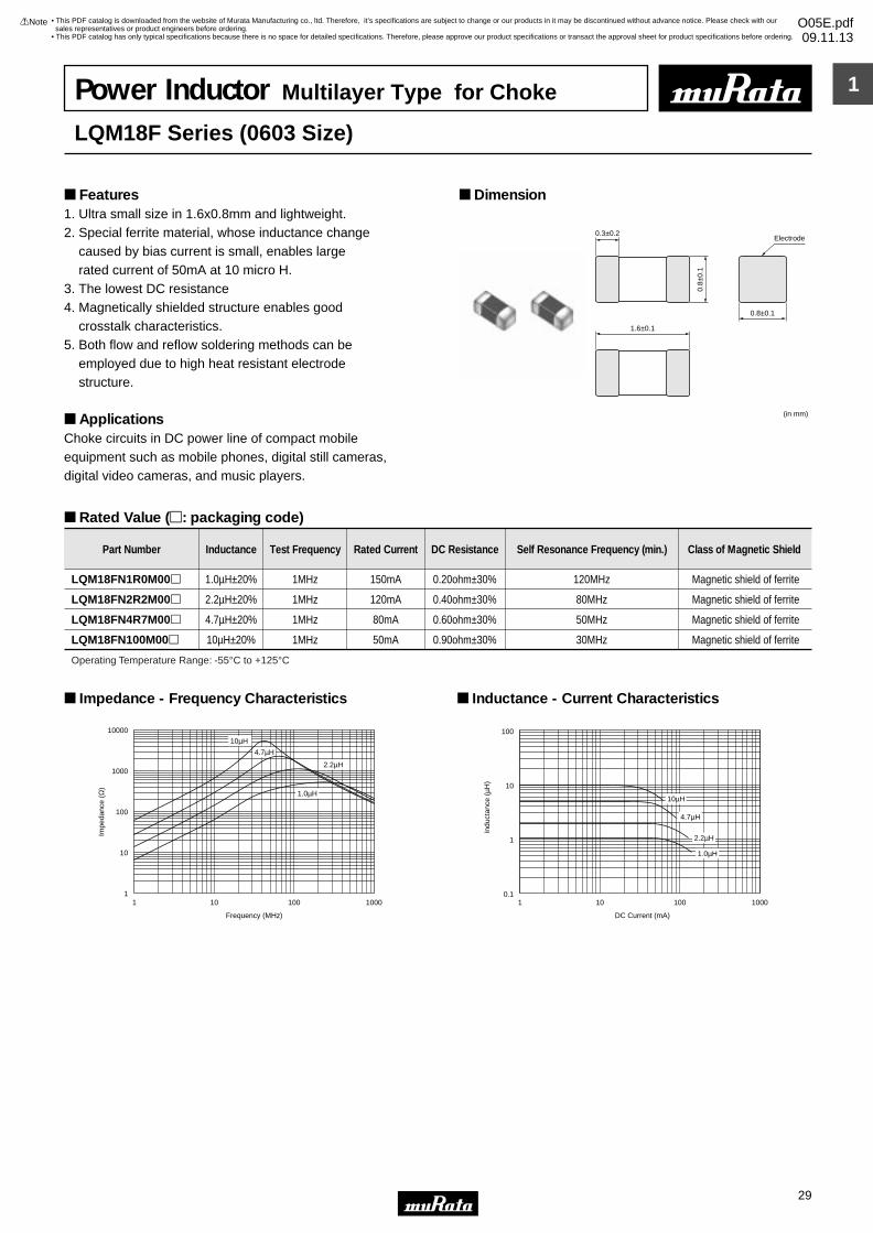
1
!Note • Please read rating and !CAUTION (for storage, operating, rating, soldering, mounting and handling) in this catalog to prevent smoking and/or burning, etc.• This catalog has only typical specifications because there is no space for detailed specifications. Therefore, please approve our product specifications or transact the approval sheet for product specifications before ordering.
29
• This PDF catalog is downloaded from the website of Murata Manufacturing co., ltd. Therefore, it’s specifications are subject to change or our products in it may be discontinued without advance notice. Please check with our sales representatives or product engineers before ordering.
• This PDF catalog has only typical specifications because there is no space for detailed specifications. Therefore, please approve our product specifications or transact the approval sheet for product specifications before ordering.
!Note O05E.pdf09.11.13
Power Inductor Multilayer Type for Choke
LQM18F Series (0603 Size)
1. Ultra small size in 1.6x0.8mm and lightweight.2. Special ferrite material, whose inductance change caused by bias current is small, enables large rated current of 50mA at 10 micro H.3. The lowest DC resistance4. Magnetically shielded structure enables good crosstalk characteristics.5. Both flow and reflow soldering methods can be employed due to high heat resistant electrode structure.
ApplicationsChoke circuits in DC power line of compact mobile equipment such as mobile phones, digital still cameras,digital video cameras, and music players.
Dimension Features
Rated Value (p: packaging code)
1.6±0.1
0.3±0.2
0.8±0.1
0.8±
0.1
(in mm)
Electrode
Part Number Inductance Test Frequency Rated Current DC Resistance Self Resonance Frequency (min.) Class of Magnetic Shield
LQM18FN1R0M00p 1.0µH±20% 1MHz 150mA 0.20ohm±30% 120MHz Magnetic shield of ferrite
LQM18FN2R2M00p 2.2µH±20% 1MHz 120mA 0.40ohm±30% 80MHz Magnetic shield of ferrite
LQM18FN4R7M00p 4.7µH±20% 1MHz 80mA 0.60ohm±30% 50MHz Magnetic shield of ferrite
LQM18FN100M00p 10µH±20% 1MHz 50mA 0.90ohm±30% 30MHz Magnetic shield of ferrite
Operating Temperature Range: -55°C to +125°C
Impe
danc
e (Ω
)
1 10 100 1000
Frequency (MHz)
1
100
1000
10
10000
10µH
4.7µH
1.0µH
2.2µH
Impedance - Frequency Characteristics
100
10
1
0.11 10 100 1000
DC Current (mA)
Indu
ctan
ce (
µH)
10µH
4.7µH
2.2µH
1.0µH
Inductance - Current Characteristics
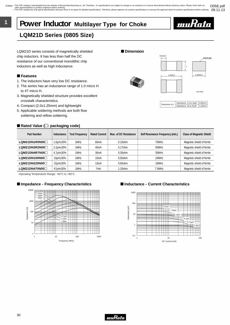
1
!Note • Please read rating and !CAUTION (for storage, operating, rating, soldering, mounting and handling) in this catalog to prevent smoking and/or burning, etc.• This catalog has only typical specifications because there is no space for detailed specifications. Therefore, please approve our product specifications or transact the approval sheet for product specifications before ordering.
30
• This PDF catalog is downloaded from the website of Murata Manufacturing co., ltd. Therefore, it’s specifications are subject to change or our products in it may be discontinued without advance notice. Please check with our sales representatives or product engineers before ordering.
• This PDF catalog has only typical specifications because there is no space for detailed specifications. Therefore, please approve our product specifications or transact the approval sheet for product specifications before ordering.
!Note O05E.pdf09.11.13
Power Inductor Multilayer Type for Choke
LQM21D Series (0805 Size)
LQM21D series consists of magnetically shielded chip inductors. It has less than half the DC resistance of our conventional monolithic chip inductors as well as high inductance.
Features1. The inductors have very low DC resistance.2. The series has an inductance range of 1.0 micro H to 47 micro H.3. Magnetically shielded structure provides excellent crosstalk characteristics.4. Compact (2.0x1.25mm) and lightweight5. Applicable soldering methods are both flow soldering and reflow soldering.
Dimension
Rated Value (p: packaging code)
2.0±0.2
0.5±0.3
1.25±0.2
t
Electrode
(in mm)
Inductance: 1.0 to 10µHDimension of t
Inductance: 22 to 47µH
0.85±0.2
1.25±0.2
Part Number Inductance Test Frequency Rated Current Max. of DC Resistance Self Resonance Frequency (min.) Class of Magnetic Shield
LQM21DN1R0N00p 1.0µH±30% 1MHz 60mA 0.10ohm 75MHz Magnetic shield of ferrite
LQM21DN2R2N00p 2.2µH±30% 1MHz 40mA 0.17ohm 50MHz Magnetic shield of ferrite
LQM21DN4R7N00p 4.7µH±30% 1MHz 30mA 0.30ohm 35MHz Magnetic shield of ferrite
LQM21DN100N00p 10µH±30% 1MHz 15mA 0.50ohm 24MHz Magnetic shield of ferrite
LQM21DN220N00p 22µH±30% 1MHz 13mA 0.65ohm 16MHz Magnetic shield of ferrite
LQM21DN470N00p 47µH±30% 1MHz 7mA 1.20ohm 7.5MHz Magnetic shield of ferrite
Operating Temperature Range: -40°C to +85°C
47µH22µH10µH
4.7µH2.2µH
1 10 100 1000
1
10
100
1000
10000
Frequency (MHz)
Impe
danc
e (Ω
)
1.0µH
Impedance - Frequency Characteristics
1 10 100
DC Current (mA)
Indu
ctan
ce (
µH)
0.1
10
1
100
1000
47µH
22µH
10µH
4.7µH
2.2µH
1.0µH
Inductance - Current Characteristics
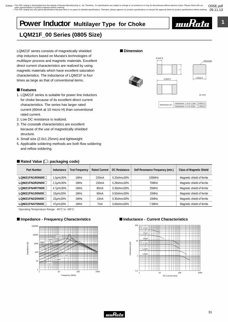
1
!Note • Please read rating and !CAUTION (for storage, operating, rating, soldering, mounting and handling) in this catalog to prevent smoking and/or burning, etc.• This catalog has only typical specifications because there is no space for detailed specifications. Therefore, please approve our product specifications or transact the approval sheet for product specifications before ordering.
31
• This PDF catalog is downloaded from the website of Murata Manufacturing co., ltd. Therefore, it’s specifications are subject to change or our products in it may be discontinued without advance notice. Please check with our sales representatives or product engineers before ordering.
• This PDF catalog has only typical specifications because there is no space for detailed specifications. Therefore, please approve our product specifications or transact the approval sheet for product specifications before ordering.
!Note O05E.pdf09.11.13
Power Inductor Multilayer Type for Choke
LQM21F_00 Series (0805 Size)
LQM21F series consists of magnetically shielded chip inductors based on Murata's technologies of multilayer process and magnetic materials. Excellent direct current characteristics are realized by using magnetic materials which have excellent saturation characteristics. The inductance of LQM21F is four times as large as that of conventional items.
Features1. LQM21F series is suitable for power line inductors for choke because of its excellent direct current characteristics. The series has larger rated current (60mA at 10 micro H) than conventional rated current.2. Low DC resistance is realized.3. The crosstalk characteristics are excellent because of the use of magnetically shielded structure.4. Small size (2.0x1.25mm) and lightweight5. Applicable soldering methods are both flow soldering and reflow soldering.
Dimension
Rated Value (p: packaging code)
2.0±0.2
0.5±0.3
t
(in mm)
Inductance: 1.0 to 2.2µHDimension of t
Inductance: 4.7 to 47µH
0.85±0.2
1.25±0.2
1.25±0.2
Electrode
Part Number Inductance Test Frequency Rated Current DC Resistance Self Resonance Frequency (min.) Class of Magnetic Shield
LQM21FN1R0N00p 1.0µH±30% 1MHz 220mA 0.20ohm±30% 105MHz Magnetic shield of ferrite
LQM21FN2R2N00p 2.2µH±30% 1MHz 150mA 0.28ohm±30% 70MHz Magnetic shield of ferrite
LQM21FN4R7N00p 4.7µH±30% 1MHz 80mA 0.30ohm±30% 25MHz Magnetic shield of ferrite
LQM21FN100N00p 10µH±30% 1MHz 60mA 0.50ohm±30% 15MHz Magnetic shield of ferrite
LQM21FN220N00p 22µH±30% 1MHz 13mA 0.35ohm±30% 15MHz Magnetic shield of ferrite
LQM21FN470N00p 47µH±30% 1MHz 7mA 0.60ohm±30% 7.5MHz Magnetic shield of ferrite
Operating Temperature Range: -40°C to +85°C
1 10 100 1000
100000
10000
1000
100
10
1
10µH
4.7µH
2.2µH
22µH
1.0µH
47µH
Frequency (MHz)
Impe
danc
e (Ω
)
Impedance - Frequency Characteristics
1 10 100 1000
100
10
0.1
1
DC Current (mA)
Indu
ctan
ce (
µH)
10µH
4.7µH
2.2µH
22µH
1.0µH
47µH
Inductance - Current Characteristics
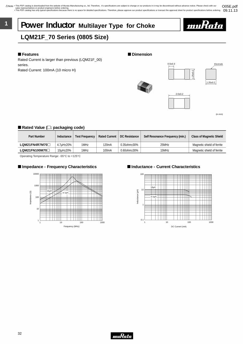
1
!Note • Please read rating and !CAUTION (for storage, operating, rating, soldering, mounting and handling) in this catalog to prevent smoking and/or burning, etc.• This catalog has only typical specifications because there is no space for detailed specifications. Therefore, please approve our product specifications or transact the approval sheet for product specifications before ordering.
32
• This PDF catalog is downloaded from the website of Murata Manufacturing co., ltd. Therefore, it’s specifications are subject to change or our products in it may be discontinued without advance notice. Please check with our sales representatives or product engineers before ordering.
• This PDF catalog has only typical specifications because there is no space for detailed specifications. Therefore, please approve our product specifications or transact the approval sheet for product specifications before ordering.
!Note O05E.pdf09.11.13
Power Inductor Multilayer Type for Choke
LQM21F_70 Series (0805 Size)
Rated Current is larger than previous (LQM21F_00)series.Rated Current: 100mA (10 micro H)
Dimension Features
Rated Value (p: packaging code)
2.0±0.2
0.5±0.3
1.25±0.2
1.25
±0.2
Electrode
(in mm)
Part Number Inductance Test Frequency Rated Current DC Resistance Self Resonance Frequency (min.) Class of Magnetic Shield
LQM21FN4R7M70p 4.7µH±20% 1MHz 120mA 0.35ohm±30% 25MHz Magnetic shield of ferrite
LQM21FN100M70p 10µH±20% 1MHz 100mA 0.60ohm±30% 15MHz Magnetic shield of ferrite
Operating Temperature Range: -55°C to +125°C
1 10 100 10001
10
100
1000
10000
Frequency (MHz)
Impe
danc
e (Ω
) 10µH4.7µH
Impedance - Frequency Characteristics
Indu
ctan
ce (
µH)
DC Current (mA)
0.1
1
10
100
1 10010 1000
10µH
4.7µH
Inductance - Current Characteristics
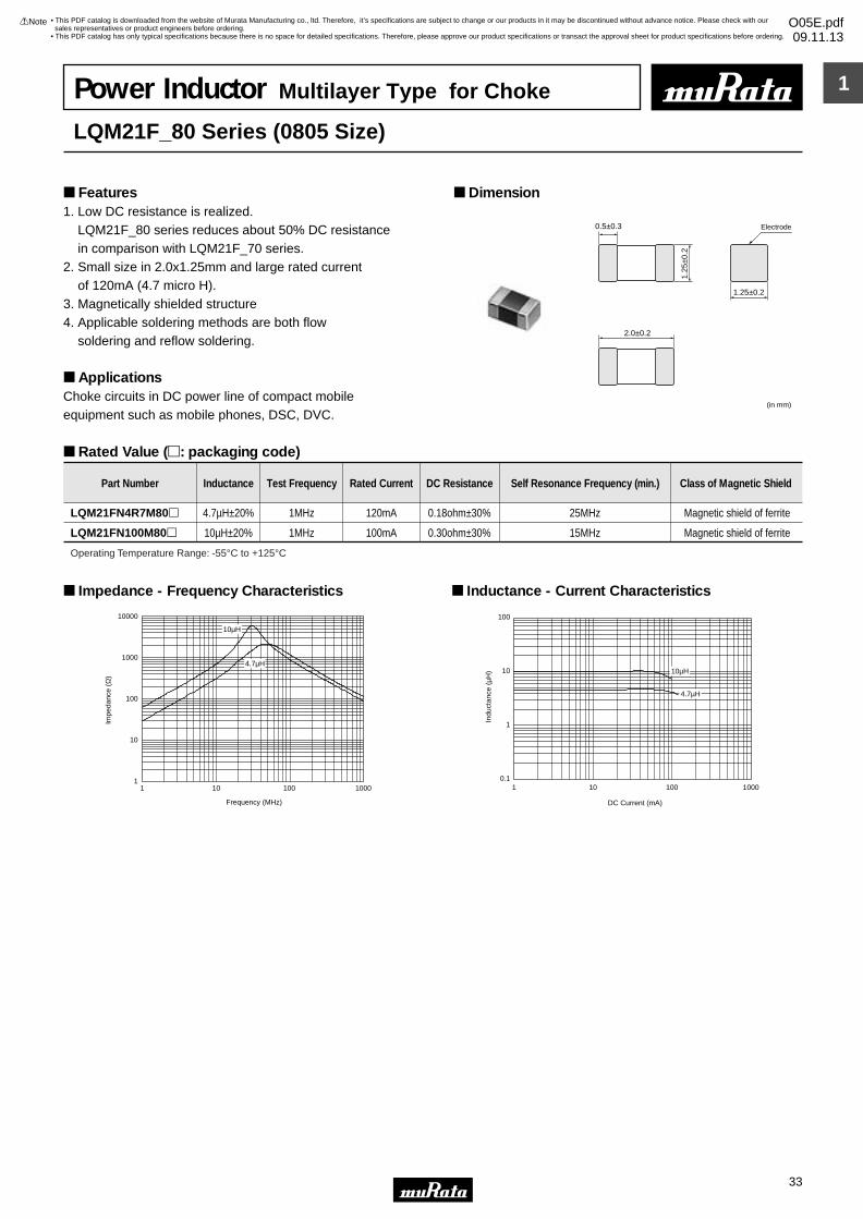
1
!Note • Please read rating and !CAUTION (for storage, operating, rating, soldering, mounting and handling) in this catalog to prevent smoking and/or burning, etc.• This catalog has only typical specifications because there is no space for detailed specifications. Therefore, please approve our product specifications or transact the approval sheet for product specifications before ordering.
33
• This PDF catalog is downloaded from the website of Murata Manufacturing co., ltd. Therefore, it’s specifications are subject to change or our products in it may be discontinued without advance notice. Please check with our sales representatives or product engineers before ordering.
• This PDF catalog has only typical specifications because there is no space for detailed specifications. Therefore, please approve our product specifications or transact the approval sheet for product specifications before ordering.
!Note O05E.pdf09.11.13
Power Inductor Multilayer Type for Choke
LQM21F_80 Series (0805 Size)
1. Low DC resistance is realized. LQM21F_80 series reduces about 50% DC resistance in comparison with LQM21F_70 series.2. Small size in 2.0x1.25mm and large rated current of 120mA (4.7 micro H). 3. Magnetically shielded structure4. Applicable soldering methods are both flow soldering and reflow soldering.
ApplicationsChoke circuits in DC power line of compact mobile equipment such as mobile phones, DSC, DVC.
Dimension Features
Rated Value (p: packaging code)
2.0±0.2
0.5±0.3
1.25±0.2
1.25
±0.2
Electrode
(in mm)
Part Number Inductance Test Frequency Rated Current DC Resistance Self Resonance Frequency (min.) Class of Magnetic Shield
LQM21FN4R7M80p 4.7µH±20% 1MHz 120mA 0.18ohm±30% 25MHz Magnetic shield of ferrite
LQM21FN100M80p 10µH±20% 1MHz 100mA 0.30ohm±30% 15MHz Magnetic shield of ferrite
Operating Temperature Range: -55°C to +125°C
1 10 100 10001
10
100
1000
10000
Frequency (MHz)
Impe
danc
e (Ω
)
10µH
4.7µH
Impedance - Frequency Characteristics
0.1
1
10
100
Indu
ctan
ce (
µH)
1 10 100 1000
DC Current (mA)
10µH
4.7µH
Inductance - Current Characteristics
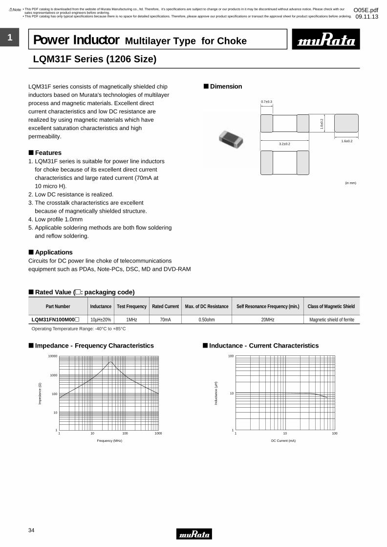
1
!Note • Please read rating and !CAUTION (for storage, operating, rating, soldering, mounting and handling) in this catalog to prevent smoking and/or burning, etc.• This catalog has only typical specifications because there is no space for detailed specifications. Therefore, please approve our product specifications or transact the approval sheet for product specifications before ordering.
34
• This PDF catalog is downloaded from the website of Murata Manufacturing co., ltd. Therefore, it’s specifications are subject to change or our products in it may be discontinued without advance notice. Please check with our sales representatives or product engineers before ordering.
• This PDF catalog has only typical specifications because there is no space for detailed specifications. Therefore, please approve our product specifications or transact the approval sheet for product specifications before ordering.
!Note O05E.pdf09.11.13
Power Inductor Multilayer Type for Choke
LQM31F Series (1206 Size)
LQM31F series consists of magnetically shielded chip inductors based on Murata's technologies of multilayer process and magnetic materials. Excellent direct current characteristics and low DC resistance are realized by using magnetic materials which have excellent saturation characteristics and high permeability.
Features1. LQM31F series is suitable for power line inductors for choke because of its excellent direct current characteristics and large rated current (70mA at 10 micro H).2. Low DC resistance is realized.3. The crosstalk characteristics are excellent because of magnetically shielded structure.4. Low profile 1.0mm5. Applicable soldering methods are both flow soldering and reflow soldering.
ApplicationsCircuits for DC power line choke of telecommunicationsequipment such as PDAs, Note-PCs, DSC, MD and DVD-RAM
Dimension
Rated Value (p: packaging code)
3.2±0.2
0.7±0.3
1.6±0.2
(in mm)
1.0±
0.2
Part Number Inductance Test Frequency Rated Current Max. of DC Resistance Self Resonance Frequency (min.) Class of Magnetic Shield
LQM31FN100M00p 10µH±20% 1MHz 70mA 0.50ohm 20MHz Magnetic shield of ferrite
Operating Temperature Range: -40°C to +85°C
1 10 100 1000
10000
1000
100
10
1
Frequency (MHz)
Impe
danc
e (Ω
)
Impedance - Frequency Characteristics
1 10 100
100
10
1
DC Current (mA)
Indu
ctan
ce (
µH)
Inductance - Current Characteristics
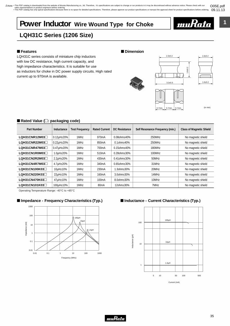
1
!Note • Please read rating and !CAUTION (for storage, operating, rating, soldering, mounting and handling) in this catalog to prevent smoking and/or burning, etc.• This catalog has only typical specifications because there is no space for detailed specifications. Therefore, please approve our product specifications or transact the approval sheet for product specifications before ordering.
35
• This PDF catalog is downloaded from the website of Murata Manufacturing co., ltd. Therefore, it’s specifications are subject to change or our products in it may be discontinued without advance notice. Please check with our sales representatives or product engineers before ordering.
• This PDF catalog has only typical specifications because there is no space for detailed specifications. Therefore, please approve our product specifications or transact the approval sheet for product specifications before ordering.
!Note O05E.pdf09.11.13
Power Inductor Wire Wound Type for Choke
LQH31C Series (1206 Size)
LQH31C series consists of miniature chip inductorswith low DC resistance, high current capacity, and high impedance characteristics. It is suitable for useas inductors for choke in DC power supply circuits. High ratedcurrent up to 970mA is available.
Dimension Features
Rated Value (p: packaging code)
2.3±0.2
1.8±
0.2
1.6±0.2
1.6±0.23.2±0.3
0.7min. 0.7min. 0.7min. (in mm)
Part Number Inductance Test Frequency Rated Current DC Resistance Self Resonance Frequency (min.) Class of Magnetic Shield
LQH31CNR12M03p 0.12µH±20% 1MHz 970mA 0.08ohm±40% 250MHz No magnetic shield
LQH31CNR22M03p 0.22µH±20% 1MHz 850mA 0.1ohm±40% 250MHz No magnetic shield
LQH31CNR47M03p 0.47µH±20% 1MHz 700mA 0.15ohm±40% 180MHz No magnetic shield
LQH31CN1R0M03p 1.0µH±20% 1MHz 510mA 0.28ohm±30% 100MHz No magnetic shield
LQH31CN2R2M03p 2.2µH±20% 1MHz 430mA 0.41ohm±30% 50MHz No magnetic shield
LQH31CN4R7M03p 4.7µH±20% 1MHz 340mA 0.65ohm±30% 31MHz No magnetic shield
LQH31CN100K03p 10µH±10% 1MHz 230mA 1.3ohm±30% 20MHz No magnetic shield
LQH31CN220K03p 22µH±10% 1MHz 160mA 3.0ohm±30% 14MHz No magnetic shield
LQH31CN470K03p 47µH±10% 1MHz 100mA 8.0ohm±30% 10MHz No magnetic shield
LQH31CN101K03p 100µH±10% 1MHz 80mA 12ohm±30% 7MHz No magnetic shield
Operating Temperature Range: -40°C to +85°C
0.01
0.1
1
10
100
1000
0.01 0.1 1 10 100 1000
Frequency (MHz)
Impe
danc
e (k
Ω)
100µH
10µH
1.0µH
Impedance - Frequency Characteristics (Typ.)
100µH
10µH
1.0µH
100
10
1
5 10 50 100 500
Current (mA)
Indu
ctan
ce (
µH)
Inductance - Current Characteristics (Typ.)
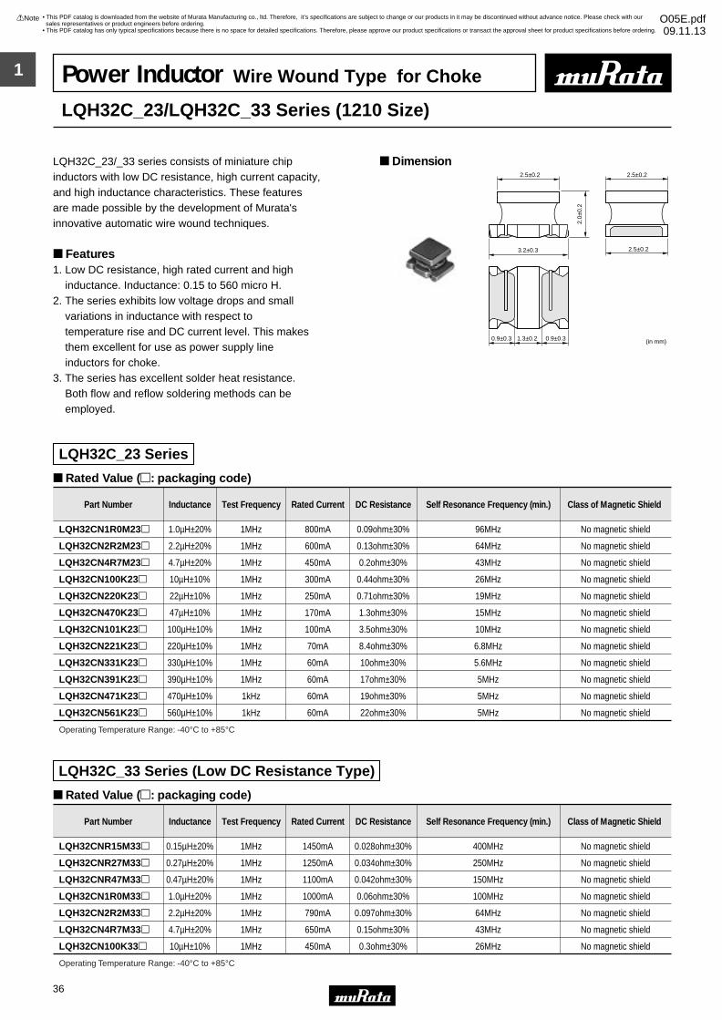
1
!Note • Please read rating and !CAUTION (for storage, operating, rating, soldering, mounting and handling) in this catalog to prevent smoking and/or burning, etc.• This catalog has only typical specifications because there is no space for detailed specifications. Therefore, please approve our product specifications or transact the approval sheet for product specifications before ordering.
36
• This PDF catalog is downloaded from the website of Murata Manufacturing co., ltd. Therefore, it’s specifications are subject to change or our products in it may be discontinued without advance notice. Please check with our sales representatives or product engineers before ordering.
• This PDF catalog has only typical specifications because there is no space for detailed specifications. Therefore, please approve our product specifications or transact the approval sheet for product specifications before ordering.
!Note O05E.pdf09.11.13
Power Inductor Wire Wound Type for Choke
LQH32C_23/LQH32C_33 Series (1210 Size)
LQH32C_23/_33 series consists of miniature chip inductors with low DC resistance, high current capacity,and high inductance characteristics. These featuresare made possible by the development of Murata's innovative automatic wire wound techniques.
Features 1. Low DC resistance, high rated current and high inductance. Inductance: 0.15 to 560 micro H.2. The series exhibits low voltage drops and small variations in inductance with respect to temperature rise and DC current level. This makes them excellent for use as power supply line inductors for choke.3. The series has excellent solder heat resistance. Both flow and reflow soldering methods can be employed.
Dimension
Rated Value (p: packaging code)
Rated Value (p: packaging code)
LQH32C_23 Series
LQH32C_33 Series (Low DC Resistance Type)
(in mm)
2.5±0.2 2.5±0.2
2.0±
0.2
2.5±0.23.2±0.3
0.9±0.3 1.3±0.2 0.9±0.3
Part Number Inductance Test Frequency Rated Current DC Resistance Self Resonance Frequency (min.) Class of Magnetic Shield
Part Number Inductance Test Frequency Rated Current DC Resistance Self Resonance Frequency (min.) Class of Magnetic Shield
LQH32CN1R0M23p 1.0µH±20% 1MHz 800mA 0.09ohm±30% 96MHz No magnetic shield
LQH32CN2R2M23p 2.2µH±20% 1MHz 600mA 0.13ohm±30% 64MHz No magnetic shield
LQH32CN4R7M23p 4.7µH±20% 1MHz 450mA 0.2ohm±30% 43MHz No magnetic shield
LQH32CN100K23p 10µH±10% 1MHz 300mA 0.44ohm±30% 26MHz No magnetic shield
LQH32CN220K23p 22µH±10% 1MHz 250mA 0.71ohm±30% 19MHz No magnetic shield
LQH32CN470K23p 47µH±10% 1MHz 170mA 1.3ohm±30% 15MHz No magnetic shield
LQH32CN101K23p 100µH±10% 1MHz 100mA 3.5ohm±30% 10MHz No magnetic shield
LQH32CN221K23p 220µH±10% 1MHz 70mA 8.4ohm±30% 6.8MHz No magnetic shield
LQH32CN331K23p 330µH±10% 1MHz 60mA 10ohm±30% 5.6MHz No magnetic shield
LQH32CN391K23p 390µH±10% 1MHz 60mA 17ohm±30% 5MHz No magnetic shield
LQH32CN471K23p 470µH±10% 1kHz 60mA 19ohm±30% 5MHz No magnetic shield
LQH32CN561K23p 560µH±10% 1kHz 60mA 22ohm±30% 5MHz No magnetic shield
LQH32CNR15M33p 0.15µH±20% 1MHz 1450mA 0.028ohm±30% 400MHz No magnetic shield
LQH32CNR27M33p 0.27µH±20% 1MHz 1250mA 0.034ohm±30% 250MHz No magnetic shield
LQH32CNR47M33p 0.47µH±20% 1MHz 1100mA 0.042ohm±30% 150MHz No magnetic shield
LQH32CN1R0M33p 1.0µH±20% 1MHz 1000mA 0.06ohm±30% 100MHz No magnetic shield
LQH32CN2R2M33p 2.2µH±20% 1MHz 790mA 0.097ohm±30% 64MHz No magnetic shield
LQH32CN4R7M33p 4.7µH±20% 1MHz 650mA 0.15ohm±30% 43MHz No magnetic shield
LQH32CN100K33p 10µH±10% 1MHz 450mA 0.3ohm±30% 26MHz No magnetic shield
Operating Temperature Range: -40°C to +85°C
Operating Temperature Range: -40°C to +85°C

1
!Note • Please read rating and !CAUTION (for storage, operating, rating, soldering, mounting and handling) in this catalog to prevent smoking and/or burning, etc.• This catalog has only typical specifications because there is no space for detailed specifications. Therefore, please approve our product specifications or transact the approval sheet for product specifications before ordering.
37
• This PDF catalog is downloaded from the website of Murata Manufacturing co., ltd. Therefore, it’s specifications are subject to change or our products in it may be discontinued without advance notice. Please check with our sales representatives or product engineers before ordering.
• This PDF catalog has only typical specifications because there is no space for detailed specifications. Therefore, please approve our product specifications or transact the approval sheet for product specifications before ordering.
!Note O05E.pdf09.11.13
0.01
0.1
1
10
100
1000
0.01 0.1 1 10 100 1000
Frequency (MHz)
Impe
danc
e (k
Ω)
100µH
10µH
1.0µH
Impedance - Frequency Characteristics (Typ.)LQH32C_23/LQH32C_33
1 10 1000100
1000
100
10
1
0.1
DC Current (mA)
Indu
ctan
ce (
µH)
100µH
10µH
1.0µH
Inductance - Current Characteristics (Typ.)LQH32C_23/LQH32C_33
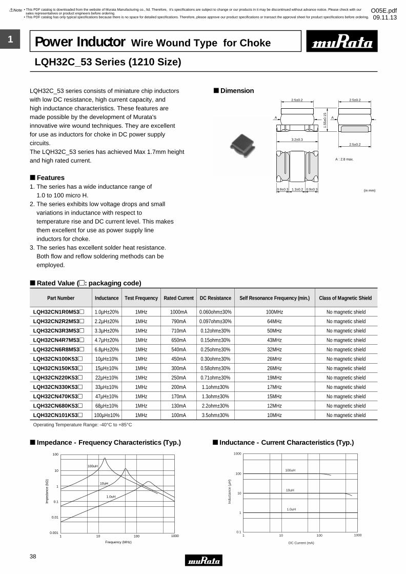
1
!Note • Please read rating and !CAUTION (for storage, operating, rating, soldering, mounting and handling) in this catalog to prevent smoking and/or burning, etc.• This catalog has only typical specifications because there is no space for detailed specifications. Therefore, please approve our product specifications or transact the approval sheet for product specifications before ordering.
38
• This PDF catalog is downloaded from the website of Murata Manufacturing co., ltd. Therefore, it’s specifications are subject to change or our products in it may be discontinued without advance notice. Please check with our sales representatives or product engineers before ordering.
• This PDF catalog has only typical specifications because there is no space for detailed specifications. Therefore, please approve our product specifications or transact the approval sheet for product specifications before ordering.
!Note O05E.pdf09.11.13
Power Inductor Wire Wound Type for Choke
LQH32C_53 Series (1210 Size)
LQH32C_53 series consists of miniature chip inductorswith low DC resistance, high current capacity, and high inductance characteristics. These features are made possible by the development of Murata's innovative wire wound techniques. They are excellent for use as inductors for choke in DC power supply circuits.The LQH32C_53 series has achieved Max 1.7mm heightand high rated current.
Features1. The series has a wide inductance range of 1.0 to 100 micro H.2. The series exhibits low voltage drops and small variations in inductance with respect to temperature rise and DC current level. This makes them excellent for use as power supply line inductors for choke.3. The series has excellent solder heat resistance. Both flow and reflow soldering methods can be employed.
Dimension
Rated Value (p: packaging code)
2.5±0.2 2.5±0.2
1.55
±0.1
5
2.5±0.23.2±0.3
A : 2.8 max.
A
0.9±0.3 1.3±0.2 0.9±0.3
A
(in mm)
Part Number Inductance Test Frequency Rated Current DC Resistance Self Resonance Frequency (min.) Class of Magnetic Shield
LQH32CN1R0M53p 1.0µH±20% 1MHz 1000mA 0.060ohm±30% 100MHz No magnetic shield
LQH32CN2R2M53p 2.2µH±20% 1MHz 790mA 0.097ohm±30% 64MHz No magnetic shield
LQH32CN3R3M53p 3.3µH±20% 1MHz 710mA 0.12ohm±30% 50MHz No magnetic shield
LQH32CN4R7M53p 4.7µH±20% 1MHz 650mA 0.15ohm±30% 43MHz No magnetic shield
LQH32CN6R8M53p 6.8µH±20% 1MHz 540mA 0.25ohm±30% 32MHz No magnetic shield
LQH32CN100K53p 10µH±10% 1MHz 450mA 0.30ohm±30% 26MHz No magnetic shield
LQH32CN150K53p 15µH±10% 1MHz 300mA 0.58ohm±30% 26MHz No magnetic shield
LQH32CN220K53p 22µH±10% 1MHz 250mA 0.71ohm±30% 19MHz No magnetic shield
LQH32CN330K53p 33µH±10% 1MHz 200mA 1.1ohm±30% 17MHz No magnetic shield
LQH32CN470K53p 47µH±10% 1MHz 170mA 1.3ohm±30% 15MHz No magnetic shield
LQH32CN680K53p 68µH±10% 1MHz 130mA 2.2ohm±30% 12MHz No magnetic shield
LQH32CN101K53p 100µH±10% 1MHz 100mA 3.5ohm±30% 10MHz No magnetic shield
Operating Temperature Range: -40°C to +85°C
1 10 100
10
100
1
0.1
0.01
0.0011000
10uH
1.0uH
Impe
danc
e (k
Ω)
Frequency (MHz)
100uH
Impedance - Frequency Characteristics (Typ.)
1 10 100
100
1000
10
1
0.11000
100uH
10uH
1.0uH
DC Current (mA)
Indu
ctan
ce (
µH)
Inductance - Current Characteristics (Typ.)
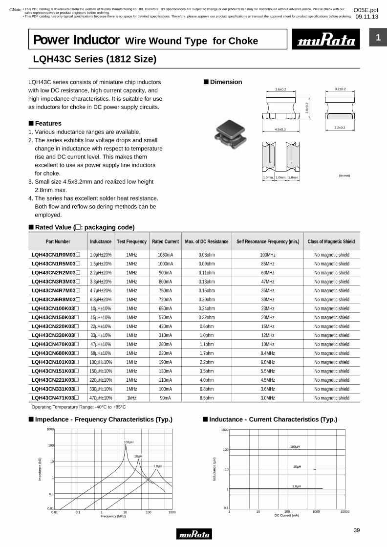
1
!Note • Please read rating and !CAUTION (for storage, operating, rating, soldering, mounting and handling) in this catalog to prevent smoking and/or burning, etc.• This catalog has only typical specifications because there is no space for detailed specifications. Therefore, please approve our product specifications or transact the approval sheet for product specifications before ordering.
39
• This PDF catalog is downloaded from the website of Murata Manufacturing co., ltd. Therefore, it’s specifications are subject to change or our products in it may be discontinued without advance notice. Please check with our sales representatives or product engineers before ordering.
• This PDF catalog has only typical specifications because there is no space for detailed specifications. Therefore, please approve our product specifications or transact the approval sheet for product specifications before ordering.
!Note O05E.pdf09.11.13
Power Inductor Wire Wound Type for Choke
LQH43C Series (1812 Size)
LQH43C series consists of miniature chip inductorswith low DC resistance, high current capacity, and high impedance characteristics. It is suitable for useas inductors for choke in DC power supply circuits.
Features1. Various inductance ranges are available.2. The series exhibits low voltage drops and small change in inductance with respect to temperature rise and DC current level. This makes them excellent to use as power supply line inductors for choke.3. Small size 4.5x3.2mm and realized low height 2.8mm max.4. The series has excellent solder heat resistance. Both flow and reflow soldering methods can be employed.
Dimension
Rated Value (p: packaging code)
3.6±0.2
4.5±0.3
2.6±
0.2
3.2±0.2
3.2±0.2
1.0min. 1.0min. 1.0min.(in mm)
Part Number Inductance Test Frequency Rated Current Max. of DC Resistance Self Resonance Frequency (min.) Class of Magnetic Shield
LQH43CN1R0M03p 1.0µH±20% 1MHz 1080mA 0.08ohm 100MHz No magnetic shield
LQH43CN1R5M03p 1.5µH±20% 1MHz 1000mA 0.09ohm 85MHz No magnetic shield
LQH43CN2R2M03p 2.2µH±20% 1MHz 900mA 0.11ohm 60MHz No magnetic shield
LQH43CN3R3M03p 3.3µH±20% 1MHz 800mA 0.13ohm 47MHz No magnetic shield
LQH43CN4R7M03p 4.7µH±20% 1MHz 750mA 0.15ohm 35MHz No magnetic shield
LQH43CN6R8M03p 6.8µH±20% 1MHz 720mA 0.20ohm 30MHz No magnetic shield
LQH43CN100K03p 10µH±10% 1MHz 650mA 0.24ohm 23MHz No magnetic shield
LQH43CN150K03p 15µH±10% 1MHz 570mA 0.32ohm 20MHz No magnetic shield
LQH43CN220K03p 22µH±10% 1MHz 420mA 0.6ohm 15MHz No magnetic shield
LQH43CN330K03p 33µH±10% 1MHz 310mA 1.0ohm 12MHz No magnetic shield
LQH43CN470K03p 47µH±10% 1MHz 280mA 1.1ohm 10MHz No magnetic shield
LQH43CN680K03p 68µH±10% 1MHz 220mA 1.7ohm 8.4MHz No magnetic shield
LQH43CN101K03p 100µH±10% 1MHz 190mA 2.2ohm 6.8MHz No magnetic shield
LQH43CN151K03p 150µH±10% 1MHz 130mA 3.5ohm 5.5MHz No magnetic shield
LQH43CN221K03p 220µH±10% 1MHz 110mA 4.0ohm 4.5MHz No magnetic shield
LQH43CN331K03p 330µH±10% 1MHz 100mA 6.8ohm 3.6MHz No magnetic shield
LQH43CN471K03p 470µH±10% 1kHz 90mA 8.5ohm 3.0MHz No magnetic shield
Operating Temperature Range: -40°C to +85°C
0.01 0.1 1 10010
100
1000
10
1
0.1
0.011000
Impe
danc
e (k
Ω)
Frequency (MHz)
1.0µH
100µH
10µH
Impedance - Frequency Characteristics (Typ.)
1 10 100 100001000
1000
100
10
1
0.1
DC Current (mA)
Indu
ctan
ce (
µH)
100µH
10µH
1.0µH
Inductance - Current Characteristics (Typ.)
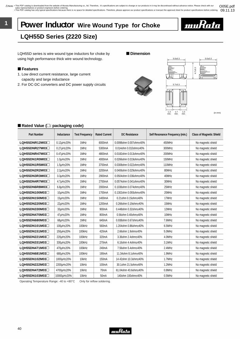
1
!Note • Please read rating and !CAUTION (for storage, operating, rating, soldering, mounting and handling) in this catalog to prevent smoking and/or burning, etc.• This catalog has only typical specifications because there is no space for detailed specifications. Therefore, please approve our product specifications or transact the approval sheet for product specifications before ordering.
40
• This PDF catalog is downloaded from the website of Murata Manufacturing co., ltd. Therefore, it’s specifications are subject to change or our products in it may be discontinued without advance notice. Please check with our sales representatives or product engineers before ordering.
• This PDF catalog has only typical specifications because there is no space for detailed specifications. Therefore, please approve our product specifications or transact the approval sheet for product specifications before ordering.
!Note O05E.pdf09.11.13
Power Inductor Wire Wound Type for Choke
LQH55D Series (2220 Size)
LQH55D series is wire wound type inductors for choke by using high performance thick wire wound technology.
Features1. Low direct current resistance, large current capacity and large inductance2. For DC-DC converters and DC power supply circuits
Dimension
Rated Value (p: packaging code)
4.7±
0.3
5.0±0.3 5.0±0.3
5.7±0.3
1.7min.
1.3min.
1.3min. (in mm)
Part Number Inductance Test Frequency Rated Current DC Resistance Self Resonance Frequency (min.) Class of Magnetic Shield
LQH55DNR12M03p 0.12µH±20% 1MHz 6000mA 0.0098ohm 0.007ohm±40% 450MHz No magnetic shield
LQH55DNR27M03p 0.27µH±20% 1MHz 5300mA 0.014ohm 0.010ohm±40% 300MHz No magnetic shield
LQH55DNR47M03p 0.47µH±20% 1MHz 4800mA 0.0182ohm 0.013ohm±40% 200MHz No magnetic shield
LQH55DN1R0M03p 1.0µH±20% 1MHz 4000mA 0.0266ohm 0.019ohm±40% 150MHz No magnetic shield
LQH55DN1R5M03p 1.5µH±20% 1MHz 3700mA 0.0308ohm 0.022ohm±40% 110MHz No magnetic shield
LQH55DN2R2M03p 2.2µH±20% 1MHz 3200mA 0.0406ohm 0.029ohm±40% 80MHz No magnetic shield
LQH55DN3R3M03p 3.3µH±20% 1MHz 2900mA 0.0504ohm 0.036ohm±40% 40MHz No magnetic shield
LQH55DN4R7M03p 4.7µH±20% 1MHz 2700mA 0.0574ohm 0.041ohm±40% 30MHz No magnetic shield
LQH55DN6R8M03p 6.8µH±20% 1MHz 2000mA 0.1036ohm 0.074ohm±40% 25MHz No magnetic shield
LQH55DN100M03p 10µH±20% 1MHz 1700mA 0.1302ohm 0.093ohm±40% 20MHz No magnetic shield
LQH55DN150M03p 15µH±20% 1MHz 1400mA 0.21ohm 0.15ohm±40% 17MHz No magnetic shield
LQH55DN220M03p 22µH±20% 1MHz 1200mA 0.266ohm 0.19ohm±40% 15MHz No magnetic shield
LQH55DN330M03p 33µH±20% 1MHz 900mA 0.448ohm 0.32ohm±40% 12MHz No magnetic shield
LQH55DN470M03p 47µH±20% 1MHz 800mA 0.56ohm 0.40ohm±40% 10MHz No magnetic shield
LQH55DN680M03p 68µH±20% 1MHz 640mA 0.938ohm 0.67ohm±40% 7.6MHz No magnetic shield
LQH55DN101M03p 100µH±20% 100kHz 560mA 1.204ohm 0.86ohm±40% 6.5MHz No magnetic shield
LQH55DN151M03p 150µH±20% 100kHz 420mA 2.66ohm 1.9ohm±40% 5.0MHz No magnetic shield
LQH55DN221M03p 220µH±20% 100kHz 320mA 3.36ohm 2.4ohm±40% 4.0MHz No magnetic shield
LQH55DN331M03p 330µH±20% 100kHz 270mA 6.16ohm 4.4ohm±40% 3.1MHz No magnetic shield
LQH55DN471M03p 470µH±20% 100kHz 240mA 7.56ohm 5.4ohm±40% 2.4MHz No magnetic shield
LQH55DN681M03p 680µH±20% 100kHz 190mA 11.34ohm 8.1ohm±40% 1.9MHz No magnetic shield
LQH55DN102M03p 1000µH±20% 10kHz 150mA 14.42ohm 10.3ohm±40% 1.7MHz No magnetic shield
LQH55DN222M03p 2200µH±20% 10kHz 100mA 30.1ohm 21.5ohm±40% 1.2MHz No magnetic shield
LQH55DN472M03p 4700µH±20% 10kHz 70mA 61.04ohm 43.6ohm±40% 0.8MHz No magnetic shield
LQH55DN103M03p 10000µH±20% 10kHz 50mA 140ohm 100ohm±40% 0.5MHz No magnetic shield
Operating Temperature Range: -40 to +80°C Only for reflow soldering.
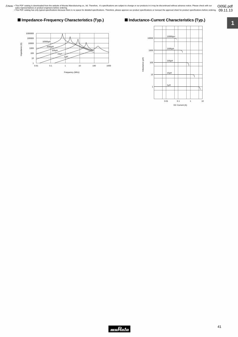
1
!Note • Please read rating and !CAUTION (for storage, operating, rating, soldering, mounting and handling) in this catalog to prevent smoking and/or burning, etc.• This catalog has only typical specifications because there is no space for detailed specifications. Therefore, please approve our product specifications or transact the approval sheet for product specifications before ordering.
41
• This PDF catalog is downloaded from the website of Murata Manufacturing co., ltd. Therefore, it’s specifications are subject to change or our products in it may be discontinued without advance notice. Please check with our sales representatives or product engineers before ordering.
• This PDF catalog has only typical specifications because there is no space for detailed specifications. Therefore, please approve our product specifications or transact the approval sheet for product specifications before ordering.
!Note O05E.pdf09.11.13
10000µH
Frequency (MHz)
10
100
1000
10000
100000
1000000
10.01 0.1 1 10 100 1000
1000µH
100µH
10µH1µH
Impe
danc
e (Ω
) Impedance-Frequency Characteristics (Typ.)
Indu
ctan
ce (
µH)
DC Current (A)
10000
1000
100
10
1
0.01 0.1 1 10
1µH
10µH
10000µH
1000µH
100µH
Inductance-Current Characteristics (Typ.)
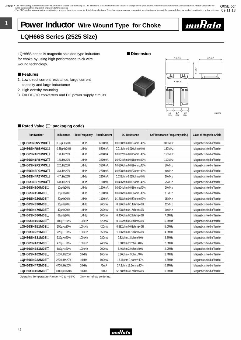
1
!Note • Please read rating and !CAUTION (for storage, operating, rating, soldering, mounting and handling) in this catalog to prevent smoking and/or burning, etc.• This catalog has only typical specifications because there is no space for detailed specifications. Therefore, please approve our product specifications or transact the approval sheet for product specifications before ordering.
42
• This PDF catalog is downloaded from the website of Murata Manufacturing co., ltd. Therefore, it’s specifications are subject to change or our products in it may be discontinued without advance notice. Please check with our sales representatives or product engineers before ordering.
• This PDF catalog has only typical specifications because there is no space for detailed specifications. Therefore, please approve our product specifications or transact the approval sheet for product specifications before ordering.
!Note O05E.pdf09.11.13
Power Inductor Wire Wound Type for Choke
LQH66S Series (2525 Size)
LQH66S series is magnetic shielded type inductorsfor choke by using high performance thick wire wound technology.
Features1. Low direct current resistance, large current capacity and large inductance2. High density mounting3. For DC-DC converters and DC power supply circuits
Dimension
Rated Value (p: packaging code)
4.7±
0.3
6.3±0.3 6.3±0.3
6.3±0.3
(in mm)1.7min.
1.3min.
1.3min.
Part Number Inductance Test Frequency Rated Current DC Resistance Self Resonance Frequency (min.) Class of Magnetic Shield
LQH66SNR27M03p 0.27µH±20% 1MHz 6000mA 0.0098ohm 0.007ohm±40% 300MHz Magnetic shield of ferrite
LQH66SNR68M03p 0.68µH±20% 1MHz 5300mA 0.014ohm 0.010ohm±40% 180MHz Magnetic shield of ferrite
LQH66SN1R0M03p 1.0µH±20% 1MHz 4700mA 0.0182ohm 0.013ohm±40% 150MHz Magnetic shield of ferrite
LQH66SN1R5M03p 1.5µH±20% 1MHz 3800mA 0.0224ohm 0.016ohm±40% 110MHz Magnetic shield of ferrite
LQH66SN2R2M03p 2.2µH±20% 1MHz 3300mA 0.0266ohm 0.019ohm±40% 80MHz Magnetic shield of ferrite
LQH66SN3R3M03p 3.3µH±20% 1MHz 2600mA 0.0308ohm 0.022ohm±40% 40MHz Magnetic shield of ferrite
LQH66SN4R7M03p 4.7µH±20% 1MHz 2200mA 0.035ohm 0.025ohm±40% 30MHz Magnetic shield of ferrite
LQH66SN6R8M03p 6.8µH±20% 1MHz 1800mA 0.0406ohm 0.029ohm±40% 25MHz Magnetic shield of ferrite
LQH66SN100M03p 10µH±20% 1MHz 1600mA 0.0504ohm 0.036ohm±40% 20MHz Magnetic shield of ferrite
LQH66SN150M03p 15µH±20% 1MHz 1300mA 0.0966ohm 0.069ohm±40% 17MHz Magnetic shield of ferrite
LQH66SN220M03p 22µH±20% 1MHz 1100mA 0.1218ohm 0.087ohm±40% 15MHz Magnetic shield of ferrite
LQH66SN330M03p 33µH±20% 1MHz 860mA 0.196ohm 0.14ohm±40% 12MHz Magnetic shield of ferrite
LQH66SN470M03p 47µH±20% 1MHz 760mA 0.238ohm 0.17ohm±40% 10MHz Magnetic shield of ferrite
LQH66SN680M03p 68µH±20% 1MHz 600mA 0.406ohm 0.29ohm±40% 7.6MHz Magnetic shield of ferrite
LQH66SN101M03p 100µH±20% 100kHz 520mA 0.504ohm 0.36ohm±40% 6.5MHz Magnetic shield of ferrite
LQH66SN151M03p 150µH±20% 100kHz 420mA 0.882ohm 0.63ohm±40% 5.0MHz Magnetic shield of ferrite
LQH66SN221M03p 220µH±20% 100kHz 350mA 1.106ohm 0.79ohm±40% 4.0MHz Magnetic shield of ferrite
LQH66SN331M03p 330µH±20% 100kHz 280mA 2.52ohm 1.8ohm±40% 3.2MHz Magnetic shield of ferrite
LQH66SN471M03p 470µH±20% 100kHz 240mA 3.08ohm 2.2ohm±40% 2.5MHz Magnetic shield of ferrite
LQH66SN681M03p 680µH±20% 100kHz 200mA 5.46ohm 3.9ohm±40% 2.0MHz Magnetic shield of ferrite
LQH66SN102M03p 1000µH±20% 10kHz 160mA 6.86ohm 4.9ohm±40% 1.7MHz Magnetic shield of ferrite
LQH66SN222M03p 2200µH±20% 10kHz 100mA 13.16ohm 9.4ohm±40% 1.2MHz Magnetic shield of ferrite
LQH66SN472M03p 4700µH±20% 10kHz 70mA 27.3ohm 19.5ohm±40% 0.8MHz Magnetic shield of ferrite
LQH66SN103M03p 10000µH±20% 10kHz 50mA 55.58ohm 39.7ohm±40% 0.5MHz Magnetic shield of ferrite
Operating Temperature Range: -40 to +85°C Only for reflow soldering.
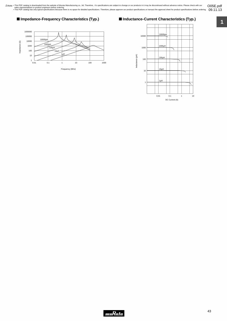
1
!Note • Please read rating and !CAUTION (for storage, operating, rating, soldering, mounting and handling) in this catalog to prevent smoking and/or burning, etc.• This catalog has only typical specifications because there is no space for detailed specifications. Therefore, please approve our product specifications or transact the approval sheet for product specifications before ordering.
43
• This PDF catalog is downloaded from the website of Murata Manufacturing co., ltd. Therefore, it’s specifications are subject to change or our products in it may be discontinued without advance notice. Please check with our sales representatives or product engineers before ordering.
• This PDF catalog has only typical specifications because there is no space for detailed specifications. Therefore, please approve our product specifications or transact the approval sheet for product specifications before ordering.
!Note O05E.pdf09.11.13
10000µH
Frequency (MHz)
Impe
danc
e (Ω
)
10
100
1000
10000
100000
1000000
10.01 0.1 1 10 100 1000
100µH
10µH
1µH
1000µH
Impedance-Frequency Characteristics (Typ.)
DC Current (A)
Indu
ctan
ce (
µH)
10000
1000
100
10
1
0.01 0.1 1 10
1µH
10µH
10000µH
1000µH
100µH
Inductance-Current Characteristics (Typ.)
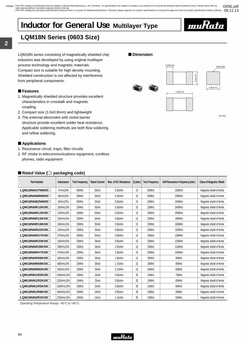
2
!Note • Please read rating and !CAUTION (for storage, operating, rating, soldering, mounting and handling) in this catalog to prevent smoking and/or burning, etc.• This catalog has only typical specifications because there is no space for detailed specifications. Therefore, please approve our product specifications or transact the approval sheet for product specifications before ordering.
44
• This PDF catalog is downloaded from the website of Murata Manufacturing co., ltd. Therefore, it’s specifications are subject to change or our products in it may be discontinued without advance notice. Please check with our sales representatives or product engineers before ordering.
• This PDF catalog has only typical specifications because there is no space for detailed specifications. Therefore, please approve our product specifications or transact the approval sheet for product specifications before ordering.
!Note O05E.pdf09.11.13
Inductor for General Use Multilayer Type
LQM18N Series (0603 Size)
LQM18N series consisting of magnetically shielded chip inductors was developed by using original multilayer process technology and magnetic materials.Compact size is suitable for high density mounting.Shielded construction is not affected by interferencefrom peripheral components.
Features1. Magnetically shielded structure provides excellent characteristics in crosstalk and magnetic coupling.2. Compact size (1.6x0.8mm) and lightweight3. The external electrodes with nickel barrier structure provide excellent solder heat resistance. Applicable soldering methods are both flow soldering and reflow soldering.
Applications1. Resonance circuit, traps, filter circuits 2. RF choke in telecommunications equipment, cordless phones, radio equipment
Dimension
Rated Value (p: packaging code)
1.6±0.15
0.35±0.15
0.8±0.15
0.8±
0.15
(in mm)
Electrode
Part Number Inductance Test Frequency Rated Current Max. of DC Resistance Q (min.) Test Frequency Self Resonance Frequency (min.) Class of Magnetic Shield
LQM18NN47NM00p 47nH±20% 50MHz 50mA 0.30ohm 10 50MHz 260MHz Magnetic shield of ferrite
LQM18NN68NM00p 68nH±20% 50MHz 50mA 0.30ohm 10 50MHz 250MHz Magnetic shield of ferrite
LQM18NN82NM00p 82nH±20% 50MHz 50mA 0.30ohm 10 50MHz 245MHz Magnetic shield of ferrite
LQM18NNR10K00p 100nH±10% 25MHz 50mA 0.50ohm 15 25MHz 240MHz Magnetic shield of ferrite
LQM18NNR12K00p 120nH±10% 25MHz 50mA 0.50ohm 15 25MHz 205MHz Magnetic shield of ferrite
LQM18NNR15K00p 150nH±10% 25MHz 50mA 0.60ohm 15 25MHz 180MHz Magnetic shield of ferrite
LQM18NNR18K00p 180nH±10% 25MHz 50mA 0.60ohm 15 25MHz 165MHz Magnetic shield of ferrite
LQM18NNR22K00p 220nH±10% 25MHz 50mA 0.80ohm 15 25MHz 150MHz Magnetic shield of ferrite
LQM18NNR27K00p 270nH±10% 25MHz 50mA 0.80ohm 15 25MHz 136MHz Magnetic shield of ferrite
LQM18NNR33K00p 330nH±10% 25MHz 35mA 0.85ohm 15 25MHz 125MHz Magnetic shield of ferrite
LQM18NNR39K00p 390nH±10% 25MHz 35mA 1.00ohm 15 25MHz 110MHz Magnetic shield of ferrite
LQM18NNR47K00p 470nH±10% 25MHz 35mA 1.35ohm 15 25MHz 105MHz Magnetic shield of ferrite
LQM18NNR56K00p 560nH±10% 25MHz 35mA 1.55ohm 15 25MHz 95MHz Magnetic shield of ferrite
LQM18NNR68K00p 680nH±10% 25MHz 35mA 1.70ohm 15 25MHz 90MHz Magnetic shield of ferrite
LQM18NNR82K00p 820nH±10% 25MHz 35mA 2.10ohm 15 25MHz 85MHz Magnetic shield of ferrite
LQM18NN1R0K00p 1000nH±10% 10MHz 25mA 0.60ohm 35 10MHz 75MHz Magnetic shield of ferrite
LQM18NN1R2K00p 1200nH±10% 10MHz 25mA 0.80ohm 35 10MHz 65MHz Magnetic shield of ferrite
LQM18NN1R5K00p 1500nH±10% 10MHz 25mA 0.80ohm 35 10MHz 60MHz Magnetic shield of ferrite
LQM18NN1R8K00p 1800nH±10% 10MHz 25mA 0.95ohm 35 10MHz 55MHz Magnetic shield of ferrite
LQM18NN2R2K00p 2200nH±10% 10MHz 15mA 1.15ohm 35 10MHz 50MHz Magnetic shield of ferrite
Operating Temperature Range: -40°C to +85°C
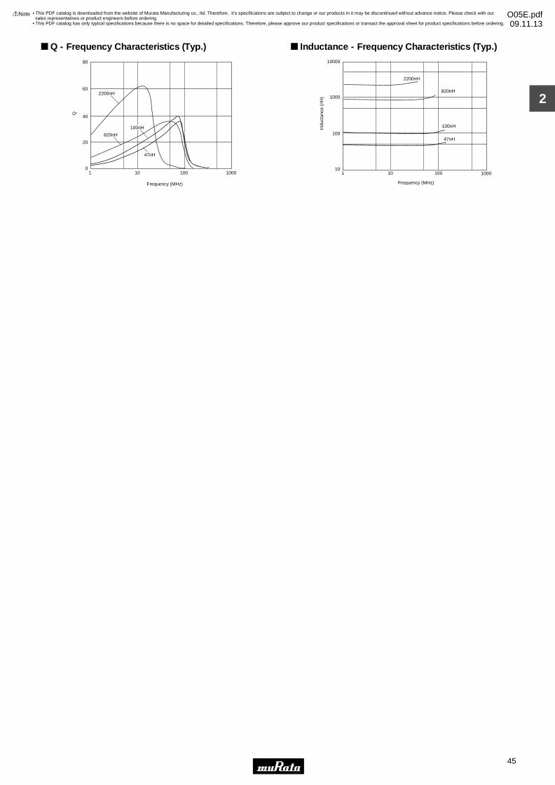
2
!Note • Please read rating and !CAUTION (for storage, operating, rating, soldering, mounting and handling) in this catalog to prevent smoking and/or burning, etc.• This catalog has only typical specifications because there is no space for detailed specifications. Therefore, please approve our product specifications or transact the approval sheet for product specifications before ordering.
45
• This PDF catalog is downloaded from the website of Murata Manufacturing co., ltd. Therefore, it’s specifications are subject to change or our products in it may be discontinued without advance notice. Please check with our sales representatives or product engineers before ordering.
• This PDF catalog has only typical specifications because there is no space for detailed specifications. Therefore, please approve our product specifications or transact the approval sheet for product specifications before ordering.
!Note O05E.pdf09.11.13
47nH
80
60
40
20
01000100101
Q
Frequency (MHz)
100nH
820nH
2200nH
Q - Frequency Characteristics (Typ.)
100nH
820nH
2200nH
1 10 100 1000
10000
1000
100
10
47nH
Frequency (MHz)
Indu
ctan
ce (
nH)
Inductance - Frequency Characteristics (Typ.)
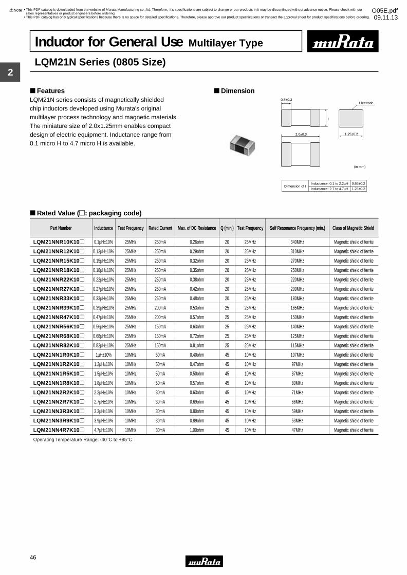
2
!Note • Please read rating and !CAUTION (for storage, operating, rating, soldering, mounting and handling) in this catalog to prevent smoking and/or burning, etc.• This catalog has only typical specifications because there is no space for detailed specifications. Therefore, please approve our product specifications or transact the approval sheet for product specifications before ordering.
46
• This PDF catalog is downloaded from the website of Murata Manufacturing co., ltd. Therefore, it’s specifications are subject to change or our products in it may be discontinued without advance notice. Please check with our sales representatives or product engineers before ordering.
• This PDF catalog has only typical specifications because there is no space for detailed specifications. Therefore, please approve our product specifications or transact the approval sheet for product specifications before ordering.
!Note O05E.pdf09.11.13
Inductor for General Use Multilayer Type
LQM21N Series (0805 Size)
LQM21N series consists of magnetically shielded chip inductors developed using Murata's original multilayer process technology and magnetic materials.The miniature size of 2.0x1.25mm enables compact design of electric equipment. Inductance range from 0.1 micro H to 4.7 micro H is available.
Dimension Features
Rated Value (p: packaging code)
2.0±0.3
0.5±0.3
1.25±0.2
t
Electrode
(in mm)
Inductance: 0.1 to 2.2µHDimension of t
Inductance: 2.7 to 4.7µH
0.85±0.2
1.25±0.2
Part Number Inductance Test Frequency Rated Current Max. of DC Resistance Q (min.) Test Frequency Self Resonance Frequency (min.) Class of Magnetic Shield
LQM21NNR10K10p 0.1µH±10% 25MHz 250mA 0.26ohm 20 25MHz 340MHz Magnetic shield of ferrite
LQM21NNR12K10p 0.12µH±10% 25MHz 250mA 0.29ohm 20 25MHz 310MHz Magnetic shield of ferrite
LQM21NNR15K10p 0.15µH±10% 25MHz 250mA 0.32ohm 20 25MHz 270MHz Magnetic shield of ferrite
LQM21NNR18K10p 0.18µH±10% 25MHz 250mA 0.35ohm 20 25MHz 250MHz Magnetic shield of ferrite
LQM21NNR22K10p 0.22µH±10% 25MHz 250mA 0.38ohm 20 25MHz 220MHz Magnetic shield of ferrite
LQM21NNR27K10p 0.27µH±10% 25MHz 250mA 0.42ohm 20 25MHz 200MHz Magnetic shield of ferrite
LQM21NNR33K10p 0.33µH±10% 25MHz 250mA 0.48ohm 20 25MHz 180MHz Magnetic shield of ferrite
LQM21NNR39K10p 0.39µH±10% 25MHz 200mA 0.53ohm 25 25MHz 165MHz Magnetic shield of ferrite
LQM21NNR47K10p 0.47µH±10% 25MHz 200mA 0.57ohm 25 25MHz 150MHz Magnetic shield of ferrite
LQM21NNR56K10p 0.56µH±10% 25MHz 150mA 0.63ohm 25 25MHz 140MHz Magnetic shield of ferrite
LQM21NNR68K10p 0.68µH±10% 25MHz 150mA 0.72ohm 25 25MHz 125MHz Magnetic shield of ferrite
LQM21NNR82K10p 0.82µH±10% 25MHz 150mA 0.81ohm 25 25MHz 115MHz Magnetic shield of ferrite
LQM21NN1R0K10p 1µH±10% 10MHz 50mA 0.40ohm 45 10MHz 107MHz Magnetic shield of ferrite
LQM21NN1R2K10p 1.2µH±10% 10MHz 50mA 0.47ohm 45 10MHz 97MHz Magnetic shield of ferrite
LQM21NN1R5K10p 1.5µH±10% 10MHz 50mA 0.50ohm 45 10MHz 87MHz Magnetic shield of ferrite
LQM21NN1R8K10p 1.8µH±10% 10MHz 50mA 0.57ohm 45 10MHz 80MHz Magnetic shield of ferrite
LQM21NN2R2K10p 2.2µH±10% 10MHz 30mA 0.63ohm 45 10MHz 71MHz Magnetic shield of ferrite
LQM21NN2R7K10p 2.7µH±10% 10MHz 30mA 0.69ohm 45 10MHz 66MHz Magnetic shield of ferrite
LQM21NN3R3K10p 3.3µH±10% 10MHz 30mA 0.80ohm 45 10MHz 59MHz Magnetic shield of ferrite
LQM21NN3R9K10p 3.9µH±10% 10MHz 30mA 0.89ohm 45 10MHz 53MHz Magnetic shield of ferrite
LQM21NN4R7K10p 4.7µH±10% 10MHz 30mA 1.00ohm 45 10MHz 47MHz Magnetic shield of ferrite
Operating Temperature Range: -40°C to +85°C
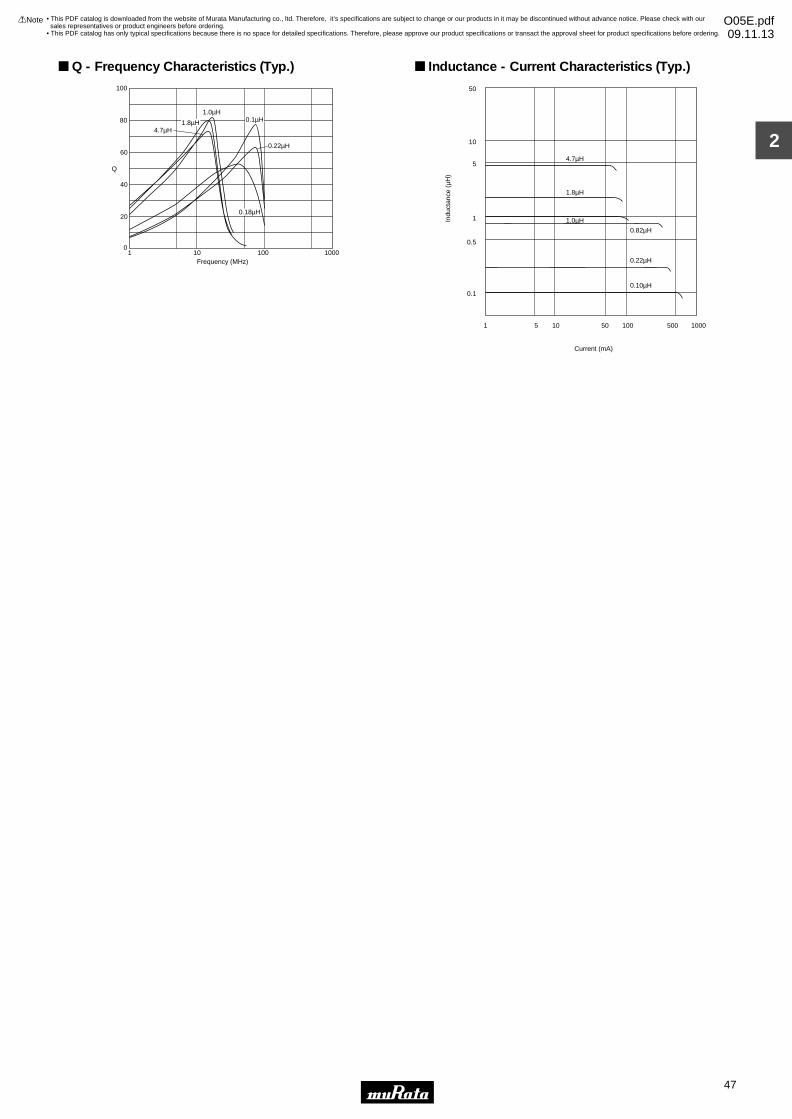
2
!Note • Please read rating and !CAUTION (for storage, operating, rating, soldering, mounting and handling) in this catalog to prevent smoking and/or burning, etc.• This catalog has only typical specifications because there is no space for detailed specifications. Therefore, please approve our product specifications or transact the approval sheet for product specifications before ordering.
47
• This PDF catalog is downloaded from the website of Murata Manufacturing co., ltd. Therefore, it’s specifications are subject to change or our products in it may be discontinued without advance notice. Please check with our sales representatives or product engineers before ordering.
• This PDF catalog has only typical specifications because there is no space for detailed specifications. Therefore, please approve our product specifications or transact the approval sheet for product specifications before ordering.
!Note O05E.pdf09.11.13
Frequency (MHz)
100
0
80
60
20
40
1 10 100 1000
Q
4.7µH
1.0µH
1.8µH 0.1µH
0.22µH
0.18µH
Q - Frequency Characteristics (Typ.)
50
10
5
1
0.5
0.1
Indu
ctan
ce (
µH)
1 5 10 50 100 500 1000
Current (mA)
1.0µH
1.8µH
4.7µH
0.22µH
0.10µH
0.82µH
Inductance - Current Characteristics (Typ.)
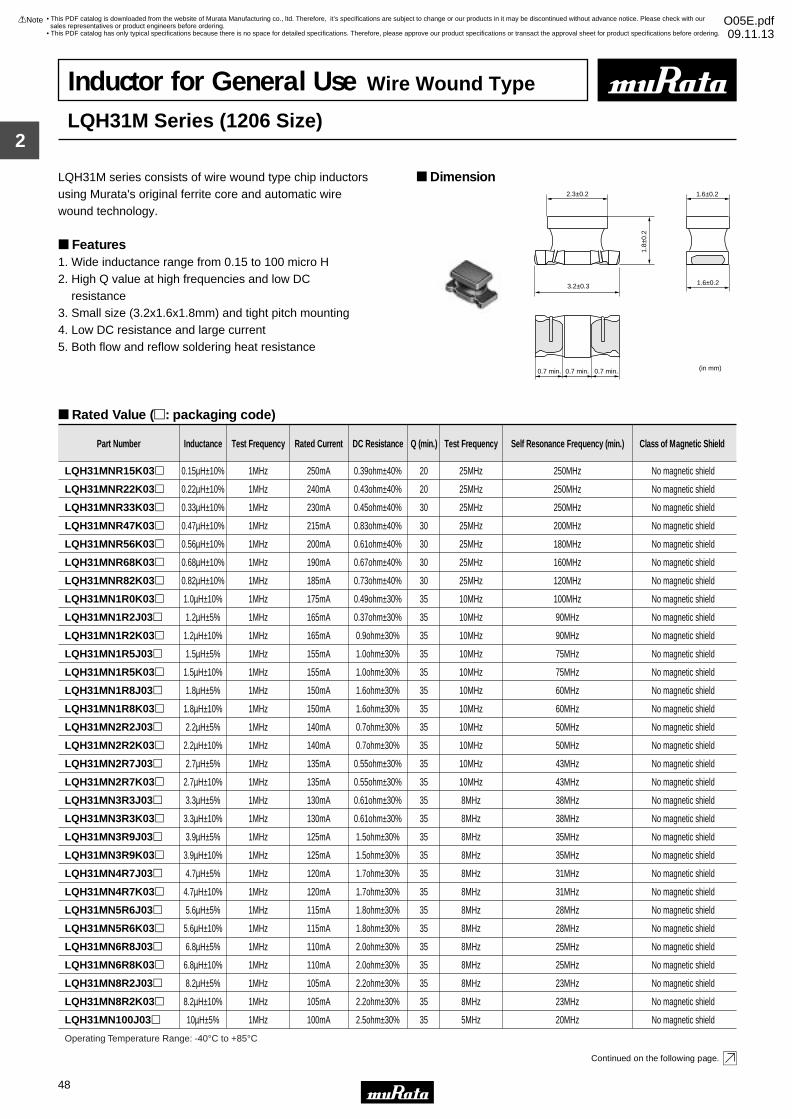
2
!Note • Please read rating and !CAUTION (for storage, operating, rating, soldering, mounting and handling) in this catalog to prevent smoking and/or burning, etc.• This catalog has only typical specifications because there is no space for detailed specifications. Therefore, please approve our product specifications or transact the approval sheet for product specifications before ordering.
48
• This PDF catalog is downloaded from the website of Murata Manufacturing co., ltd. Therefore, it’s specifications are subject to change or our products in it may be discontinued without advance notice. Please check with our sales representatives or product engineers before ordering.
• This PDF catalog has only typical specifications because there is no space for detailed specifications. Therefore, please approve our product specifications or transact the approval sheet for product specifications before ordering.
!Note O05E.pdf09.11.13
Inductor for General Use Wire Wound Type
LQH31M Series (1206 Size)
LQH31M series consists of wire wound type chip inductorsusing Murata's original ferrite core and automatic wire wound technology.
Features1. Wide inductance range from 0.15 to 100 micro H2. High Q value at high frequencies and low DC resistance 3. Small size (3.2x1.6x1.8mm) and tight pitch mounting4. Low DC resistance and large current5. Both flow and reflow soldering heat resistance
Dimension
Rated Value (p: packaging code)
Continued on the following page.
2.3±0.2
1.8±
0.2
1.6±0.2
1.6±0.23.2±0.3
0.7 min. 0.7 min. 0.7 min. (in mm)
Part Number Inductance Test Frequency Rated Current DC Resistance Q (min.) Test Frequency Self Resonance Frequency (min.) Class of Magnetic Shield
LQH31MNR15K03p 0.15µH±10% 1MHz 250mA 0.39ohm±40% 20 25MHz 250MHz No magnetic shield
LQH31MNR22K03p 0.22µH±10% 1MHz 240mA 0.43ohm±40% 20 25MHz 250MHz No magnetic shield
LQH31MNR33K03p 0.33µH±10% 1MHz 230mA 0.45ohm±40% 30 25MHz 250MHz No magnetic shield
LQH31MNR47K03p 0.47µH±10% 1MHz 215mA 0.83ohm±40% 30 25MHz 200MHz No magnetic shield
LQH31MNR56K03p 0.56µH±10% 1MHz 200mA 0.61ohm±40% 30 25MHz 180MHz No magnetic shield
LQH31MNR68K03p 0.68µH±10% 1MHz 190mA 0.67ohm±40% 30 25MHz 160MHz No magnetic shield
LQH31MNR82K03p 0.82µH±10% 1MHz 185mA 0.73ohm±40% 30 25MHz 120MHz No magnetic shield
LQH31MN1R0K03p 1.0µH±10% 1MHz 175mA 0.49ohm±30% 35 10MHz 100MHz No magnetic shield
LQH31MN1R2J03p 1.2µH±5% 1MHz 165mA 0.37ohm±30% 35 10MHz 90MHz No magnetic shield
LQH31MN1R2K03p 1.2µH±10% 1MHz 165mA 0.9ohm±30% 35 10MHz 90MHz No magnetic shield
LQH31MN1R5J03p 1.5µH±5% 1MHz 155mA 1.0ohm±30% 35 10MHz 75MHz No magnetic shield
LQH31MN1R5K03p 1.5µH±10% 1MHz 155mA 1.0ohm±30% 35 10MHz 75MHz No magnetic shield
LQH31MN1R8J03p 1.8µH±5% 1MHz 150mA 1.6ohm±30% 35 10MHz 60MHz No magnetic shield
LQH31MN1R8K03p 1.8µH±10% 1MHz 150mA 1.6ohm±30% 35 10MHz 60MHz No magnetic shield
LQH31MN2R2J03p 2.2µH±5% 1MHz 140mA 0.7ohm±30% 35 10MHz 50MHz No magnetic shield
LQH31MN2R2K03p 2.2µH±10% 1MHz 140mA 0.7ohm±30% 35 10MHz 50MHz No magnetic shield
LQH31MN2R7J03p 2.7µH±5% 1MHz 135mA 0.55ohm±30% 35 10MHz 43MHz No magnetic shield
LQH31MN2R7K03p 2.7µH±10% 1MHz 135mA 0.55ohm±30% 35 10MHz 43MHz No magnetic shield
LQH31MN3R3J03p 3.3µH±5% 1MHz 130mA 0.61ohm±30% 35 8MHz 38MHz No magnetic shield
LQH31MN3R3K03p 3.3µH±10% 1MHz 130mA 0.61ohm±30% 35 8MHz 38MHz No magnetic shield
LQH31MN3R9J03p 3.9µH±5% 1MHz 125mA 1.5ohm±30% 35 8MHz 35MHz No magnetic shield
LQH31MN3R9K03p 3.9µH±10% 1MHz 125mA 1.5ohm±30% 35 8MHz 35MHz No magnetic shield
LQH31MN4R7J03p 4.7µH±5% 1MHz 120mA 1.7ohm±30% 35 8MHz 31MHz No magnetic shield
LQH31MN4R7K03p 4.7µH±10% 1MHz 120mA 1.7ohm±30% 35 8MHz 31MHz No magnetic shield
Operating Temperature Range: -40°C to +85°C
LQH31MN5R6J03p 5.6µH±5% 1MHz 115mA 1.8ohm±30% 35 8MHz 28MHz No magnetic shield
LQH31MN5R6K03p 5.6µH±10% 1MHz 115mA 1.8ohm±30% 35 8MHz 28MHz No magnetic shield
LQH31MN6R8J03p 6.8µH±5% 1MHz 110mA 2.0ohm±30% 35 8MHz 25MHz No magnetic shield
LQH31MN6R8K03p 6.8µH±10% 1MHz 110mA 2.0ohm±30% 35 8MHz 25MHz No magnetic shield
LQH31MN8R2J03p 8.2µH±5% 1MHz 105mA 2.2ohm±30% 35 8MHz 23MHz No magnetic shield
LQH31MN8R2K03p 8.2µH±10% 1MHz 105mA 2.2ohm±30% 35 8MHz 23MHz No magnetic shield
LQH31MN100J03p 10µH±5% 1MHz 100mA 2.5ohm±30% 35 5MHz 20MHz No magnetic shield
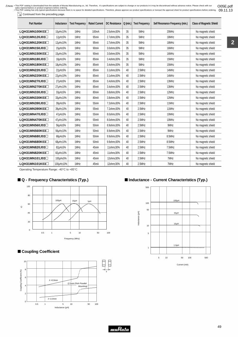
2
!Note • Please read rating and !CAUTION (for storage, operating, rating, soldering, mounting and handling) in this catalog to prevent smoking and/or burning, etc.• This catalog has only typical specifications because there is no space for detailed specifications. Therefore, please approve our product specifications or transact the approval sheet for product specifications before ordering.
49
• This PDF catalog is downloaded from the website of Murata Manufacturing co., ltd. Therefore, it’s specifications are subject to change or our products in it may be discontinued without advance notice. Please check with our sales representatives or product engineers before ordering.
• This PDF catalog has only typical specifications because there is no space for detailed specifications. Therefore, please approve our product specifications or transact the approval sheet for product specifications before ordering.
!Note O05E.pdf09.11.13
Continued from the preceding page.
Coupling Coefficient
10
8
6
4
2
00.5 1 5 10 50 100
Inductance (µH)
Cou
plin
g C
oeffi
cien
t (%
)
R
R=0.9mm
R=2.0mm
(2.5mm Pitch Parallel Mounting)
Part Number Inductance Test Frequency Rated Current DC Resistance Q (min.) Test Frequency Self Resonance Frequency (min.) Class of Magnetic Shield
LQH31MN100K03p 10µH±10% 1MHz 100mA 2.5ohm±30% 35 5MHz 20MHz No magnetic shield
LQH31MN120J03p 12µH±5% 1MHz 95mA 2.7ohm±30% 35 5MHz 18MHz No magnetic shield
LQH31MN120K03p 12µH±10% 1MHz 95mA 2.7ohm±30% 35 5MHz 18MHz No magnetic shield
LQH31MN150J03p 15µH±5% 1MHz 90mA 3.0ohm±30% 35 5MHz 16MHz No magnetic shield
LQH31MN150K03p 15µH±10% 1MHz 90mA 3.0ohm±30% 35 5MHz 16MHz No magnetic shield
LQH31MN180J03p 18µH±5% 1MHz 85mA 3.4ohm±30% 35 5MHz 15MHz No magnetic shield
LQH31MN180K03p 18µH±10% 1MHz 85mA 3.4ohm±30% 35 5MHz 15MHz No magnetic shield
LQH31MN220J03p 22µH±5% 1MHz 85mA 3.1ohm±30% 40 2.5MHz 14MHz No magnetic shield
LQH31MN220K03p 22µH±10% 1MHz 85mA 3.1ohm±30% 40 2.5MHz 14MHz No magnetic shield
LQH31MN270J03p 27µH±5% 1MHz 85mA 3.4ohm±30% 40 2.5MHz 13MHz No magnetic shield
LQH31MN270K03p 27µH±10% 1MHz 85mA 3.4ohm±30% 40 2.5MHz 13MHz No magnetic shield
LQH31MN330J03p 33µH±5% 1MHz 80mA 3.8ohm±30% 40 2.5MHz 12MHz No magnetic shield
LQH31MN330K03p 33µH±10% 1MHz 80mA 3.8ohm±30% 40 2.5MHz 12MHz No magnetic shield
LQH31MN390J03p 39µH±5% 1MHz 55mA 7.2ohm±30% 40 2.5MHz 11MHz No magnetic shield
LQH31MN390K03p 39µH±10% 1MHz 55mA 7.2ohm±30% 40 2.5MHz 11MHz No magnetic shield
LQH31MN470J03p 47µH±5% 1MHz 55mA 8.0ohm±30% 40 2.5MHz 10MHz No magnetic shield
LQH31MN470K03p 47µH±10% 1MHz 55mA 8.0ohm±30% 40 2.5MHz 10MHz No magnetic shield
LQH31MN560J03p 56µH±5% 1MHz 50mA 8.9ohm±30% 40 2.5MHz 9MHz No magnetic shield
LQH31MN560K03p 56µH±10% 1MHz 50mA 8.9ohm±30% 40 2.5MHz 9MHz No magnetic shield
LQH31MN680J03p 68µH±5% 1MHz 50mA 9.9ohm±30% 40 2.5MHz 8.5MHz No magnetic shield
LQH31MN680K03p 68µH±10% 1MHz 50mA 9.9ohm±30% 40 2.5MHz 8.5MHz No magnetic shield
LQH31MN820J03p 82µH±5% 1MHz 45mA 11ohm±30% 40 2.5MHz 7.5MHz No magnetic shield
LQH31MN820K03p 82µH±10% 1MHz 45mA 11ohm±30% 40 2.5MHz 7.5MHz No magnetic shield
LQH31MN101J03p 100µH±5% 1MHz 45mA 12ohm±30% 40 2.5MHz 7MHz No magnetic shield
LQH31MN101K03p 100µH±10% 1MHz 45mA 12ohm±30% 40 2.5MHz 7MHz No magnetic shield
Operating Temperature Range: -40°C to +85°C
0
20
40
60
80
100
0.5 1 5 10 50 100
Frequency (MHz)
Q
100µH 10µH 1µH
Q - Frequency Characteristics (Typ.)
500
100
50
10
5
1
100µH
33µH
10µH
1.0µH
5 10 50 100 500
Indu
ctan
ce (
µH)
Current (mA)
Inductance - Current Characteristics (Typ.)
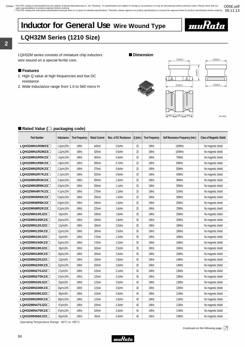
2
!Note • Please read rating and !CAUTION (for storage, operating, rating, soldering, mounting and handling) in this catalog to prevent smoking and/or burning, etc.• This catalog has only typical specifications because there is no space for detailed specifications. Therefore, please approve our product specifications or transact the approval sheet for product specifications before ordering.
50
• This PDF catalog is downloaded from the website of Murata Manufacturing co., ltd. Therefore, it’s specifications are subject to change or our products in it may be discontinued without advance notice. Please check with our sales representatives or product engineers before ordering.
• This PDF catalog has only typical specifications because there is no space for detailed specifications. Therefore, please approve our product specifications or transact the approval sheet for product specifications before ordering.
!Note O05E.pdf09.11.13
Inductor for General Use Wire Wound Type
LQH32M Series (1210 Size)
LQH32M series consists of miniature chip inductors wire wound on a special ferrite core.
Features1. High Q value at high frequencies and low DC resistance2. Wide inductance range from 1.0 to 560 micro H
Dimension
Rated Value (p: packaging code)
Continued on the following page.
(in mm)
2.5±0.2 2.5±0.2
2.0±
0.2
2.5±0.23.2±0.3
0.9±0.3 1.3±0.2 0.9±0.3
Part Number Inductance Test Frequency Rated Current Max. of DC Resistance Q (min.) Test Frequency Self Resonance Frequency (min.) Class of Magnetic Shield
LQH32MN1R0M23p 1.0µH±20% 1MHz 445mA 0.5ohm 20 1MHz 100MHz No magnetic shield
LQH32MN1R2M23p 1.2µH±20% 1MHz 425mA 0.6ohm 20 1MHz 100MHz No magnetic shield
LQH32MN1R5K23p 1.5µH±10% 1MHz 400mA 0.6ohm 20 1MHz 75MHz No magnetic shield
LQH32MN1R8K23p 1.8µH±10% 1MHz 390mA 0.7ohm 20 1MHz 60MHz No magnetic shield
LQH32MN2R2K23p 2.2µH±10% 1MHz 370mA 0.8ohm 20 1MHz 50MHz No magnetic shield
LQH32MN2R7K23p 2.7µH±10% 1MHz 320mA 0.9ohm 20 1MHz 43MHz No magnetic shield
LQH32MN3R3K23p 3.3µH±10% 1MHz 300mA 1.0ohm 20 1MHz 38MHz No magnetic shield
LQH32MN3R9K23p 3.9µH±10% 1MHz 290mA 1.1ohm 20 1MHz 35MHz No magnetic shield
LQH32MN4R7K23p 4.7µH±10% 1MHz 270mA 1.2ohm 20 1MHz 31MHz No magnetic shield
LQH32MN5R6K23p 5.6µH±10% 1MHz 250mA 1.3ohm 20 1MHz 28MHz No magnetic shield
LQH32MN6R8K23p 6.8µH±10% 1MHz 240mA 1.5ohm 20 1MHz 25MHz No magnetic shield
LQH32MN8R2K23p 8.2µH±10% 1MHz 225mA 1.6ohm 20 1MHz 23MHz No magnetic shield
LQH32MN100J23p 10µH±5% 1MHz 190mA 1.8ohm 35 1MHz 20MHz No magnetic shield
LQH32MN100K23p 10µH±10% 1MHz 190mA 1.8ohm 35 1MHz 20MHz No magnetic shield
LQH32MN120J23p 12µH±5% 1MHz 180mA 2.0ohm 35 1MHz 18MHz No magnetic shield
LQH32MN120K23p 12µH±10% 1MHz 180mA 2.0ohm 35 1MHz 18MHz No magnetic shield
LQH32MN150J23p 15µH±5% 1MHz 170mA 2.2ohm 35 1MHz 16MHz No magnetic shield
LQH32MN150K23p 15µH±10% 1MHz 170mA 2.2ohm 35 1MHz 16MHz No magnetic shield
LQH32MN180J23p 18µH±5% 1MHz 165mA 2.5ohm 35 1MHz 15MHz No magnetic shield
LQH32MN180K23p 18µH±10% 1MHz 165mA 2.5ohm 35 1MHz 15MHz No magnetic shield
LQH32MN220J23p 22µH±5% 1MHz 150mA 2.8ohm 35 1MHz 14MHz No magnetic shield
LQH32MN220K23p 22µH±10% 1MHz 150mA 2.8ohm 35 1MHz 14MHz No magnetic shield
LQH32MN270J23p 27µH±5% 1MHz 125mA 3.1ohm 35 1MHz 13MHz No magnetic shield
LQH32MN270K23p 27µH±10% 1MHz 125mA 3.1ohm 35 1MHz 13MHz No magnetic shield
Operating Temperature Range: -40°C to +85°C
LQH32MN330J23p 33µH±5% 1MHz 115mA 3.5ohm 40 1MHz 12MHz No magnetic shield
LQH32MN330K23p 33µH±10% 1MHz 115mA 3.5ohm 40 1MHz 12MHz No magnetic shield
LQH32MN390J23p 39µH±5% 1MHz 110mA 3.9ohm 40 1MHz 11MHz No magnetic shield
LQH32MN390K23p 39µH±10% 1MHz 110mA 3.9ohm 40 1MHz 11MHz No magnetic shield
LQH32MN470J23p 47µH±5% 1MHz 100mA 4.3ohm 40 1MHz 11MHz No magnetic shield
LQH32MN470K23p 47µH±10% 1MHz 100mA 4.3ohm 40 1MHz 11MHz No magnetic shield
LQH32MN560J23p 56µH±5% 1MHz 85mA 4.9ohm 40 1MHz 10MHz No magnetic shield
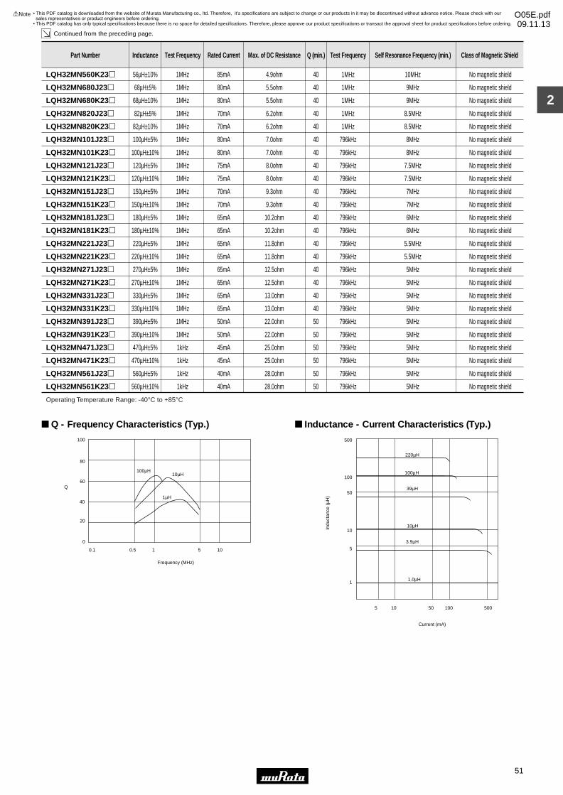
2
!Note • Please read rating and !CAUTION (for storage, operating, rating, soldering, mounting and handling) in this catalog to prevent smoking and/or burning, etc.• This catalog has only typical specifications because there is no space for detailed specifications. Therefore, please approve our product specifications or transact the approval sheet for product specifications before ordering.
51
• This PDF catalog is downloaded from the website of Murata Manufacturing co., ltd. Therefore, it’s specifications are subject to change or our products in it may be discontinued without advance notice. Please check with our sales representatives or product engineers before ordering.
• This PDF catalog has only typical specifications because there is no space for detailed specifications. Therefore, please approve our product specifications or transact the approval sheet for product specifications before ordering.
!Note O05E.pdf09.11.13
Continued from the preceding page.
Part Number Inductance Test Frequency Rated Current Max. of DC Resistance Q (min.) Test Frequency Self Resonance Frequency (min.) Class of Magnetic Shield
LQH32MN560K23p 56µH±10% 1MHz 85mA 4.9ohm 40 1MHz 10MHz No magnetic shield
LQH32MN680J23p 68µH±5% 1MHz 80mA 5.5ohm 40 1MHz 9MHz No magnetic shield
LQH32MN680K23p 68µH±10% 1MHz 80mA 5.5ohm 40 1MHz 9MHz No magnetic shield
LQH32MN820J23p 82µH±5% 1MHz 70mA 6.2ohm 40 1MHz 8.5MHz No magnetic shield
LQH32MN820K23p 82µH±10% 1MHz 70mA 6.2ohm 40 1MHz 8.5MHz No magnetic shield
LQH32MN101J23p 100µH±5% 1MHz 80mA 7.0ohm 40 796kHz 8MHz No magnetic shield
LQH32MN101K23p 100µH±10% 1MHz 80mA 7.0ohm 40 796kHz 8MHz No magnetic shield
LQH32MN121J23p 120µH±5% 1MHz 75mA 8.0ohm 40 796kHz 7.5MHz No magnetic shield
LQH32MN121K23p 120µH±10% 1MHz 75mA 8.0ohm 40 796kHz 7.5MHz No magnetic shield
LQH32MN151J23p 150µH±5% 1MHz 70mA 9.3ohm 40 796kHz 7MHz No magnetic shield
LQH32MN151K23p 150µH±10% 1MHz 70mA 9.3ohm 40 796kHz 7MHz No magnetic shield
LQH32MN181J23p 180µH±5% 1MHz 65mA 10.2ohm 40 796kHz 6MHz No magnetic shield
LQH32MN181K23p 180µH±10% 1MHz 65mA 10.2ohm 40 796kHz 6MHz No magnetic shield
LQH32MN221J23p 220µH±5% 1MHz 65mA 11.8ohm 40 796kHz 5.5MHz No magnetic shield
LQH32MN221K23p 220µH±10% 1MHz 65mA 11.8ohm 40 796kHz 5.5MHz No magnetic shield
LQH32MN271J23p 270µH±5% 1MHz 65mA 12.5ohm 40 796kHz 5MHz No magnetic shield
LQH32MN271K23p 270µH±10% 1MHz 65mA 12.5ohm 40 796kHz 5MHz No magnetic shield
LQH32MN331J23p 330µH±5% 1MHz 65mA 13.0ohm 40 796kHz 5MHz No magnetic shield
LQH32MN331K23p 330µH±10% 1MHz 65mA 13.0ohm 40 796kHz 5MHz No magnetic shield
LQH32MN391J23p 390µH±5% 1MHz 50mA 22.0ohm 50 796kHz 5MHz No magnetic shield
LQH32MN391K23p 390µH±10% 1MHz 50mA 22.0ohm 50 796kHz 5MHz No magnetic shield
LQH32MN471J23p 470µH±5% 1kHz 45mA 25.0ohm 50 796kHz 5MHz No magnetic shield
LQH32MN471K23p 470µH±10% 1kHz 45mA 25.0ohm 50 796kHz 5MHz No magnetic shield
LQH32MN561J23p 560µH±5% 1kHz 40mA 28.0ohm 50 796kHz 5MHz No magnetic shield
LQH32MN561K23p 560µH±10% 1kHz 40mA 28.0ohm 50 796kHz 5MHz No magnetic shield
Operating Temperature Range: -40°C to +85°C
0
20
40
60
80
100
0.1 0.5 1 5 10
Frequency (MHz)
Q
100µH10µH
1µH
Q - Frequency Characteristics (Typ.)
500
100
50
10
5
1
100µH
5 10 50 100 500
Indu
ctan
ce (
µH)
Current (mA)
220µH
39µH
10µH
3.9µH
1.0µH
Inductance - Current Characteristics (Typ.)
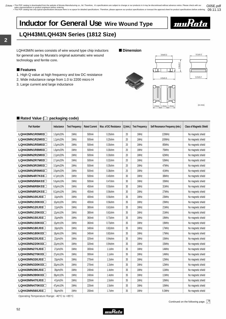
2
!Note • Please read rating and !CAUTION (for storage, operating, rating, soldering, mounting and handling) in this catalog to prevent smoking and/or burning, etc.• This catalog has only typical specifications because there is no space for detailed specifications. Therefore, please approve our product specifications or transact the approval sheet for product specifications before ordering.
52
• This PDF catalog is downloaded from the website of Murata Manufacturing co., ltd. Therefore, it’s specifications are subject to change or our products in it may be discontinued without advance notice. Please check with our sales representatives or product engineers before ordering.
• This PDF catalog has only typical specifications because there is no space for detailed specifications. Therefore, please approve our product specifications or transact the approval sheet for product specifications before ordering.
!Note O05E.pdf09.11.13
Inductor for General Use Wire Wound Type
LQH43M/LQH43N Series (1812 Size)
LQH43M/N series consists of wire wound type chip inductors for general use by Murata's original automatic wire wound technology and ferrite core.
Features1. High Q value at high frequency and low DC resistance2. Wide inductance range from 1.0 to 2200 micro H3. Large current and large inductance
Dimension
Rated Value (p: packaging code)
Continued on the following page.
3.6±0.2
4.5±0.3
2.6±
0.2
3.2±0.2
3.2±0.2
1.0min. 1.0min. 1.0min.(in mm)
Part Number Inductance Test Frequency Rated Current Max. of DC Resistance Q (min.) Test Frequency Self Resonance Frequency (min.) Class of Magnetic Shield
LQH43MN1R0M03p 1.0µH±20% 1MHz 500mA 0.20ohm 20 1MHz 120MHz No magnetic shield
LQH43MN1R2M03p 1.2µH±20% 1MHz 500mA 0.20ohm 20 1MHz 100MHz No magnetic shield
LQH43MN1R5M03p 1.5µH±20% 1MHz 500mA 0.30ohm 20 1MHz 85MHz No magnetic shield
LQH43MN1R8M03p 1.8µH±20% 1MHz 500mA 0.30ohm 20 1MHz 75MHz No magnetic shield
LQH43MN2R2M03p 2.2µH±20% 1MHz 500mA 0.30ohm 20 1MHz 62MHz No magnetic shield
LQH43MN2R7M03p 2.7µH±20% 1MHz 500mA 0.32ohm 20 1MHz 53MHz No magnetic shield
LQH43MN3R3M03p 3.3µH±20% 1MHz 500mA 0.35ohm 20 1MHz 47MHz No magnetic shield
LQH43MN3R9M03p 3.9µH±20% 1MHz 500mA 0.38ohm 20 1MHz 41MHz No magnetic shield
LQH43MN4R7K03p 4.7µH±10% 1MHz 500mA 0.40ohm 30 1MHz 38MHz No magnetic shield
LQH43MN5R6K03p 5.6µH±10% 1MHz 500mA 0.47ohm 30 1MHz 33MHz No magnetic shield
LQH43MN6R8K03p 6.8µH±10% 1MHz 450mA 0.50ohm 30 1MHz 31MHz No magnetic shield
LQH43MN8R2K03p 8.2µH±10% 1MHz 450mA 0.56ohm 30 1MHz 27MHz No magnetic shield
LQH43MN100J03p 10µH±5% 1MHz 400mA 0.56ohm 35 1MHz 23MHz No magnetic shield
LQH43MN100K03p 10µH±10% 1MHz 400mA 0.56ohm 35 1MHz 23MHz No magnetic shield
LQH43MN120J03p 12µH±5% 1MHz 380mA 0.62ohm 35 1MHz 21MHz No magnetic shield
LQH43MN120K03p 12µH±10% 1MHz 380mA 0.62ohm 35 1MHz 21MHz No magnetic shield
LQH43MN150J03p 15µH±5% 1MHz 360mA 0.73ohm 35 1MHz 19MHz No magnetic shield
LQH43MN150K03p 15µH±10% 1MHz 360mA 0.73ohm 35 1MHz 19MHz No magnetic shield
LQH43MN180J03p 18µH±5% 1MHz 340mA 0.82ohm 35 1MHz 17MHz No magnetic shield
LQH43MN180K03p 18µH±10% 1MHz 340mA 0.82ohm 35 1MHz 17MHz No magnetic shield
LQH43MN220J03p 22µH±5% 1MHz 320mA 0.94ohm 35 1MHz 15MHz No magnetic shield
LQH43MN220K03p 22µH±10% 1MHz 320mA 0.94ohm 35 1MHz 15MHz No magnetic shield
LQH43MN270J03p 27µH±5% 1MHz 300mA 1.1ohm 35 1MHz 14MHz No magnetic shield
LQH43MN270K03p 27µH±10% 1MHz 300mA 1.1ohm 35 1MHz 14MHz No magnetic shield
Operating Temperature Range: -40°C to +85°C
LQH43MN330J03p 33µH±5% 1MHz 270mA 1.2ohm 35 1MHz 12MHz No magnetic shield
LQH43MN330K03p 33µH±10% 1MHz 270mA 1.2ohm 35 1MHz 12MHz No magnetic shield
LQH43MN390J03p 39µH±5% 1MHz 240mA 1.4ohm 35 1MHz 11MHz No magnetic shield
LQH43MN390K03p 39µH±10% 1MHz 240mA 1.4ohm 35 1MHz 11MHz No magnetic shield
LQH43MN470J03p 47µH±5% 1MHz 220mA 1.5ohm 35 1MHz 10MHz No magnetic shield
LQH43MN470K03p 47µH±10% 1MHz 220mA 1.5ohm 35 1MHz 10MHz No magnetic shield
LQH43MN560J03p 56µH±5% 1MHz 200mA 1.7ohm 35 1MHz 9.3MHz No magnetic shield
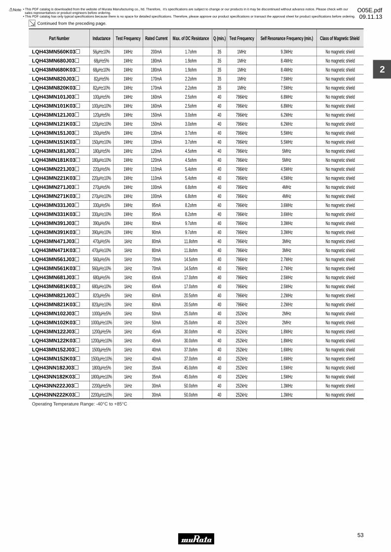
2
!Note • Please read rating and !CAUTION (for storage, operating, rating, soldering, mounting and handling) in this catalog to prevent smoking and/or burning, etc.• This catalog has only typical specifications because there is no space for detailed specifications. Therefore, please approve our product specifications or transact the approval sheet for product specifications before ordering.
53
• This PDF catalog is downloaded from the website of Murata Manufacturing co., ltd. Therefore, it’s specifications are subject to change or our products in it may be discontinued without advance notice. Please check with our sales representatives or product engineers before ordering.
• This PDF catalog has only typical specifications because there is no space for detailed specifications. Therefore, please approve our product specifications or transact the approval sheet for product specifications before ordering.
!Note O05E.pdf09.11.13
Continued from the preceding page.
Part Number Inductance Test Frequency Rated Current Max. of DC Resistance Q (min.) Test Frequency Self Resonance Frequency (min.) Class of Magnetic Shield
LQH43MN560K03p 56µH±10% 1MHz 200mA 1.7ohm 35 1MHz 9.3MHz No magnetic shield
LQH43MN680J03p 68µH±5% 1MHz 180mA 1.9ohm 35 1MHz 8.4MHz No magnetic shield
LQH43MN680K03p 68µH±10% 1MHz 180mA 1.9ohm 35 1MHz 8.4MHz No magnetic shield
LQH43MN820J03p 82µH±5% 1MHz 170mA 2.2ohm 35 1MHz 7.5MHz No magnetic shield
LQH43MN820K03p 82µH±10% 1MHz 170mA 2.2ohm 35 1MHz 7.5MHz No magnetic shield
LQH43MN101J03p 100µH±5% 1MHz 160mA 2.5ohm 40 796kHz 6.8MHz No magnetic shield
LQH43MN101K03p 100µH±10% 1MHz 160mA 2.5ohm 40 796kHz 6.8MHz No magnetic shield
LQH43MN121J03p 120µH±5% 1MHz 150mA 3.0ohm 40 796kHz 6.2MHz No magnetic shield
LQH43MN121K03p 120µH±10% 1MHz 150mA 3.0ohm 40 796kHz 6.2MHz No magnetic shield
LQH43MN151J03p 150µH±5% 1MHz 130mA 3.7ohm 40 796kHz 5.5MHz No magnetic shield
LQH43MN151K03p 150µH±10% 1MHz 130mA 3.7ohm 40 796kHz 5.5MHz No magnetic shield
LQH43MN181J03p 180µH±5% 1MHz 120mA 4.5ohm 40 796kHz 5MHz No magnetic shield
LQH43MN181K03p 180µH±10% 1MHz 120mA 4.5ohm 40 796kHz 5MHz No magnetic shield
LQH43MN221J03p 220µH±5% 1MHz 110mA 5.4ohm 40 796kHz 4.5MHz No magnetic shield
LQH43MN221K03p 220µH±10% 1MHz 110mA 5.4ohm 40 796kHz 4.5MHz No magnetic shield
LQH43MN271J03p 270µH±5% 1MHz 100mA 6.8ohm 40 796kHz 4MHz No magnetic shield
LQH43MN271K03p 270µH±10% 1MHz 100mA 6.8ohm 40 796kHz 4MHz No magnetic shield
LQH43MN331J03p 330µH±5% 1MHz 95mA 8.2ohm 40 796kHz 3.6MHz No magnetic shield
LQH43MN331K03p 330µH±10% 1MHz 95mA 8.2ohm 40 796kHz 3.6MHz No magnetic shield
LQH43MN391J03p 390µH±5% 1MHz 90mA 9.7ohm 40 796kHz 3.3MHz No magnetic shield
LQH43MN391K03p 390µH±10% 1MHz 90mA 9.7ohm 40 796kHz 3.3MHz No magnetic shield
LQH43MN471J03p 470µH±5% 1kHz 80mA 11.8ohm 40 796kHz 3MHz No magnetic shield
LQH43MN471K03p 470µH±10% 1kHz 80mA 11.8ohm 40 796kHz 3MHz No magnetic shield
LQH43MN561J03p 560µH±5% 1kHz 70mA 14.5ohm 40 796kHz 2.7MHz No magnetic shield
LQH43MN561K03p 560µH±10% 1kHz 70mA 14.5ohm 40 796kHz 2.7MHz No magnetic shield
LQH43MN681J03p 680µH±5% 1kHz 65mA 17.0ohm 40 796kHz 2.5MHz No magnetic shield
LQH43MN681K03p 680µH±10% 1kHz 65mA 17.0ohm 40 796kHz 2.5MHz No magnetic shield
LQH43MN821J03p 820µH±5% 1kHz 60mA 20.5ohm 40 796kHz 2.2MHz No magnetic shield
LQH43MN821K03p 820µH±10% 1kHz 60mA 20.5ohm 40 796kHz 2.2MHz No magnetic shield
LQH43MN102J03p 1000µH±5% 1kHz 50mA 25.0ohm 40 252kHz 2MHz No magnetic shield
LQH43MN102K03p 1000µH±10% 1kHz 50mA 25.0ohm 40 252kHz 2MHz No magnetic shield
LQH43MN122J03p 1200µH±5% 1kHz 45mA 30.0ohm 40 252kHz 1.8MHz No magnetic shield
LQH43MN122K03p 1200µH±10% 1kHz 45mA 30.0ohm 40 252kHz 1.8MHz No magnetic shield
LQH43MN152J03p 1500µH±5% 1kHz 40mA 37.0ohm 40 252kHz 1.6MHz No magnetic shield
LQH43MN152K03p 1500µH±10% 1kHz 40mA 37.0ohm 40 252kHz 1.6MHz No magnetic shield
LQH43NN182J03p 1800µH±5% 1kHz 35mA 45.0ohm 40 252kHz 1.5MHz No magnetic shield
LQH43NN182K03p 1800µH±10% 1kHz 35mA 45.0ohm 40 252kHz 1.5MHz No magnetic shield
LQH43NN222J03p 2200µH±5% 1kHz 30mA 50.0ohm 40 252kHz 1.3MHz No magnetic shield
LQH43NN222K03p 2200µH±10% 1kHz 30mA 50.0ohm 40 252kHz 1.3MHz No magnetic shield
Operating Temperature Range: -40°C to +85°C
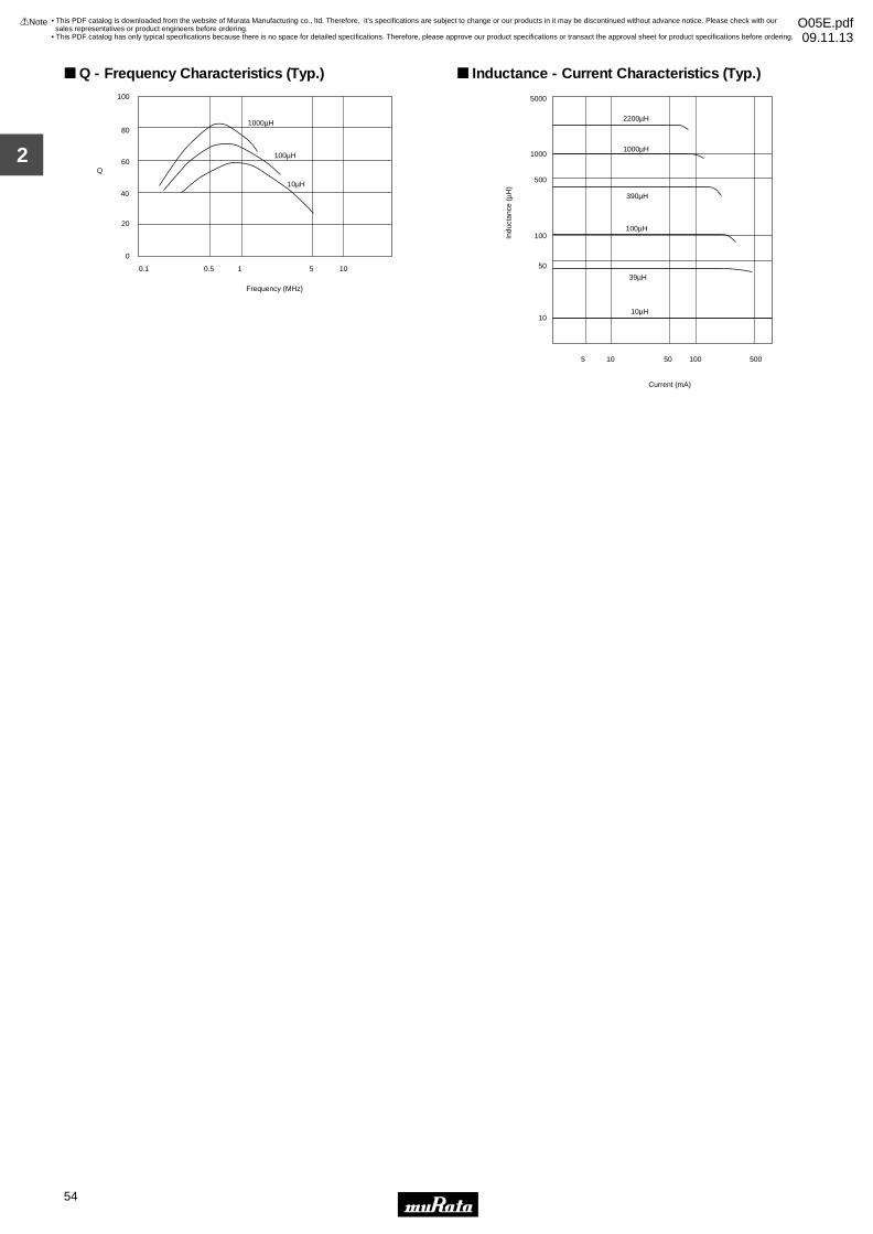
2
!Note • Please read rating and !CAUTION (for storage, operating, rating, soldering, mounting and handling) in this catalog to prevent smoking and/or burning, etc.• This catalog has only typical specifications because there is no space for detailed specifications. Therefore, please approve our product specifications or transact the approval sheet for product specifications before ordering.
54
• This PDF catalog is downloaded from the website of Murata Manufacturing co., ltd. Therefore, it’s specifications are subject to change or our products in it may be discontinued without advance notice. Please check with our sales representatives or product engineers before ordering.
• This PDF catalog has only typical specifications because there is no space for detailed specifications. Therefore, please approve our product specifications or transact the approval sheet for product specifications before ordering.
!Note O05E.pdf09.11.13
0
20
40
60
80
100
0.1 0.5 1 5 10
Frequency (MHz)
Q
1000µH
100µH
10µH
Q - Frequency Characteristics (Typ.)
5000
1000
500
100
50
10
100µH
5 10 50 100 500
Indu
ctan
ce (
µH)
Current (mA)
390µH
1000µH
2200µH
39µH
10µH
Inductance - Current Characteristics (Typ.)
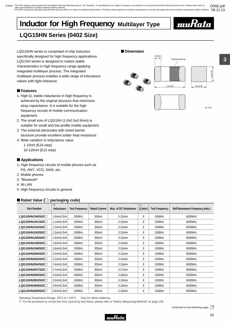
3
!Note • Please read rating and !CAUTION (for storage, operating, rating, soldering, mounting and handling) in this catalog to prevent smoking and/or burning, etc.• This catalog has only typical specifications because there is no space for detailed specifications. Therefore, please approve our product specifications or transact the approval sheet for product specifications before ordering.
55
• This PDF catalog is downloaded from the website of Murata Manufacturing co., ltd. Therefore, it’s specifications are subject to change or our products in it may be discontinued without advance notice. Please check with our sales representatives or product engineers before ordering.
• This PDF catalog has only typical specifications because there is no space for detailed specifications. Therefore, please approve our product specifications or transact the approval sheet for product specifications before ordering.
!Note O05E.pdf09.11.13
0.5±0.05
(in mm)
1.0±0.05
0.5±
0.05
0.25±0.1
Polarity Marking
Part Number Inductance Test Frequency Rated Current Max. of DC Resistance Q (min.) Test Frequency Self Resonance Frequency (min.)
LQG15HN1N0S02p 1.0nH±0.3nH 100MHz 300mA 0.10ohm 8 100MHz 6000MHz
LQG15HN1N1S02p 1.1nH±0.3nH 100MHz 300mA 0.10ohm 8 100MHz 6000MHz
LQG15HN1N2S02p 1.2nH±0.3nH 100MHz 300mA 0.10ohm 8 100MHz 6000MHz
LQG15HN1N3S02p 1.3nH±0.3nH 100MHz 300mA 0.10ohm 8 100MHz 6000MHz
LQG15HN1N5S02p 1.5nH±0.3nH 100MHz 300mA 0.10ohm 8 100MHz 6000MHz
LQG15HN1N6S02p 1.6nH±0.3nH 100MHz 300mA 0.10ohm 8 100MHz 6000MHz
LQG15HN1N8S02p 1.8nH±0.3nH 100MHz 300mA 0.10ohm 8 100MHz 6000MHz
LQG15HN2N0S02p 2.0nH±0.3nH 100MHz 300mA 0.12ohm 8 100MHz 6000MHz
LQG15HN2N2S02p 2.2nH±0.3nH 100MHz 300mA 0.15ohm 8 100MHz 6000MHz
LQG15HN2N4S02p 2.4nH±0.3nH 100MHz 300mA 0.16ohm 8 100MHz 6000MHz
LQG15HN2N7S02p 2.7nH±0.3nH 100MHz 300mA 0.17ohm 8 100MHz 6000MHz
LQG15HN3N0S02p 3.0nH±0.3nH 100MHz 300mA 0.18ohm 8 100MHz 6000MHz
LQG15HN3N3S02p 3.3nH±0.3nH 100MHz 300mA 0.19ohm 8 100MHz 6000MHz
LQG15HN3N6S02p 3.6nH±0.3nH 100MHz 300mA 0.19ohm 8 100MHz 6000MHz
LQG15HN3N9S02p 3.9nH±0.3nH 100MHz 300mA 0.19ohm 8 100MHz 6000MHz
Operating Temperature Range: -55°C to +125°C Only for reflow soldering.
Inductor for High Frequency Multilayer Type
LQG15HN Series (0402 Size)
LQG15HN series is comprised of chip inductors specifically designed for high frequency applications.LQG15H series is designed to realize stable characteristics in high frequency range applying integrated multilayer process. The integrated multilayer process enables a wide range of inductance values with tight tolerance.
Features1. High-Q, stable inductance in high frequency is achieved by the original structure that minimizes stray capacitance. It is suitable for the high frequency circuits of mobile communication equipment.2. The small size of LQG15H (1.0x0.5x0.5mm) is suitable for small and low profile mobile equipment.3. The external electrodes with nickel barrier structure provide excellent solder heat resistance.4. Wide variation in inductance value 1-10nH (E24 step) 10-120nH (E12 step)
Applications1. High frequency circuits of mobile phones such as PA, ANT, VCO, SAW, etc.2. Mobile phones3. "Bluetooth"4. W-LAN5. High frequency circuits in general
Dimension
Rated Value (p: packaging code)
Continued on the following page.
*1 For the procedure to correct the error caused by test fixture, please refer to "Notice (Measuring Method)" on page 105.
*1 *1
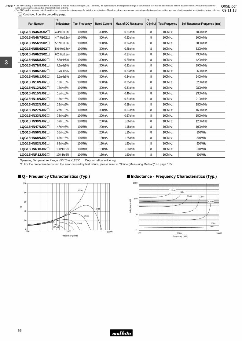
3
!Note • Please read rating and !CAUTION (for storage, operating, rating, soldering, mounting and handling) in this catalog to prevent smoking and/or burning, etc.• This catalog has only typical specifications because there is no space for detailed specifications. Therefore, please approve our product specifications or transact the approval sheet for product specifications before ordering.
56
• This PDF catalog is downloaded from the website of Murata Manufacturing co., ltd. Therefore, it’s specifications are subject to change or our products in it may be discontinued without advance notice. Please check with our sales representatives or product engineers before ordering.
• This PDF catalog has only typical specifications because there is no space for detailed specifications. Therefore, please approve our product specifications or transact the approval sheet for product specifications before ordering.
!Note O05E.pdf09.11.13
LQG15HN4N7S02p 4.7nH±0.3nH 100MHz 300mA 0.23ohm 8 100MHz 6000MHz
LQG15HN5N1S02p 5.1nH±0.3nH 100MHz 300mA 0.24ohm 8 100MHz 6000MHz
LQG15HN5N6S02p 5.6nH±0.3nH 100MHz 300mA 0.26ohm 8 100MHz 5300MHz
LQG15HN6N2S02p 6.2nH±0.3nH 100MHz 300mA 0.27ohm 8 100MHz 4300MHz
LQG15HN6N8J02p 6.8nH±5% 100MHz 300mA 0.29ohm 8 100MHz 4200MHz
LQG15HN7N5J02p 7.5nH±5% 100MHz 300mA 0.31ohm 8 100MHz 3900MHz
LQG15HN8N2J02p 8.2nH±5% 100MHz 300mA 0.33ohm 8 100MHz 3600MHz
Part Number Inductance Test Frequency Rated Current Max. of DC Resistance Q (min.) Test Frequency Self Resonance Frequency (min.)
LQG15HN9N1J02p 9.1nH±5% 100MHz 300mA 0.34ohm 8 100MHz 3400MHz
LQG15HN10NJ02p 10nH±5% 100MHz 300mA 0.35ohm 8 100MHz 3200MHz
LQG15HN12NJ02p 12nH±5% 100MHz 300mA 0.41ohm 8 100MHz 2800MHz
LQG15HN15NJ02p 15nH±5% 100MHz 300mA 0.46ohm 8 100MHz 2300MHz
LQG15HN18NJ02p 18nH±5% 100MHz 300mA 0.51ohm 8 100MHz 2100MHz
LQG15HN22NJ02p 22nH±5% 100MHz 300mA 0.58ohm 8 100MHz 1800MHz
LQG15HN27NJ02p 27nH±5% 100MHz 300mA 0.67ohm 8 100MHz 1600MHz
LQG15HN33NJ02p 33nH±5% 100MHz 200mA 0.67ohm 8 100MHz 1500MHz
LQG15HN39NJ02p 39nH±5% 100MHz 200mA 1.06ohm 8 100MHz 1200MHz
LQG15HN47NJ02p 47nH±5% 100MHz 200mA 1.15ohm 8 100MHz 1000MHz
LQG15HN56NJ02p 56nH±5% 100MHz 200mA 1.20ohm 8 100MHz 800MHz
LQG15HN68NJ02p 68nH±5% 100MHz 180mA 1.25ohm 8 100MHz 800MHz
LQG15HN82NJ02p 82nH±5% 100MHz 150mA 1.60ohm 8 100MHz 600MHz
LQG15HNR10J02p 100nH±5% 100MHz 150mA 1.60ohm 8 100MHz 600MHz
LQG15HNR12J02p 120nH±5% 100MHz 150mA 1.60ohm 8 100MHz 600MHz
Operating Temperature Range: -55°C to +125°C Only for reflow soldering.
100 1000 10000
Frequency (MHz)
100
80
60
40
20
0
Q
1.5nH
4.7nH
12nH
33nH68nH
120nH
Q - Frequency Characteristics (Typ.)
100 1000 10000
Frequency (MHz)
1000
100
10
1
Indu
ctan
ce (
nH)
1.5nH
12nH
4.7nH
33nH
68nH120nH
Inductance - Frequency Characteristics (Typ.)
LQG15HN4N3S02p 4.3nH±0.3nH 100MHz 300mA 0.21ohm 8 100MHz 6000MHz
Continued from the preceding page.
*1 For the procedure to correct the error caused by test fixture, please refer to "Notice (Measuring Method)" on page 105.
*1 *1

3
!Note • Please read rating and !CAUTION (for storage, operating, rating, soldering, mounting and handling) in this catalog to prevent smoking and/or burning, etc.• This catalog has only typical specifications because there is no space for detailed specifications. Therefore, please approve our product specifications or transact the approval sheet for product specifications before ordering.
57
• This PDF catalog is downloaded from the website of Murata Manufacturing co., ltd. Therefore, it’s specifications are subject to change or our products in it may be discontinued without advance notice. Please check with our sales representatives or product engineers before ordering.
• This PDF catalog has only typical specifications because there is no space for detailed specifications. Therefore, please approve our product specifications or transact the approval sheet for product specifications before ordering.
!Note O05E.pdf09.11.13
0.5±0.05
(in mm)
1.0±0.05
0.5±
0.05
0.25±0.1
Polarity Marking
Part Number Inductance Test Frequency Rated Current Max. of DC Resistance Q (min.) Test Frequency Self Resonance Frequency (min.)
LQG15HS1N0S02p 1.0nH±0.3nH 100MHz 300mA 0.07ohm 8 100MHz 10000MHz
LQG15HS1N1S02p 1.1nH±0.3nH 100MHz 300mA 0.09ohm 8 100MHz 6000MHz
LQG15HS1N2S02p 1.2nH±0.3nH 100MHz 300mA 0.09ohm 8 100MHz 6000MHz
LQG15HS1N3S02p 1.3nH±0.3nH 100MHz 300mA 0.09ohm 8 100MHz 6000MHz
LQG15HS1N5S02p 1.5nH±0.3nH 100MHz 300mA 0.1ohm 8 100MHz 6000MHz
LQG15HS1N6S02p 1.6nH±0.3nH 100MHz 300mA 0.1ohm 8 100MHz 6000MHz
Operating Temperature Range: -55°C to +125°C Only for reflow soldering.
Inductor for High Frequency Multilayer Type
LQG15HS Series (0402 Size)
LQG15HS series is comprised of chip inductorsspecifically designed for high frequency applications. LQG15H series is designed to realize stable characteristics in high frequency range applying integrated multilayer process. The integrated multilayer process enables a wide range of inductance values with tight tolerance.Since recent mobile phones install color LCDs and camera modules, the power consumption becomes higher.In order to reduce power consumption a low DC resistance is strongly required. LQG15HS has achieved the lowest DC resistance.
Features1. High-Q, stable inductance in high frequency is achieved by the original structure that minimizes stray capacitance. It is suitable for the high frequency circuits of mobile communication equipment.2. The small size of LQG15H (1.0x0.5x0.5mm) is suitable for small and low profile mobile equipment.3. The external electrodes with nickel barrier structure provide excellent solder heat resistance.4. Wide variation in inductance value 1-10nH (E24 step) 10-270nH (E12 step)
Applications1. High frequency circuits of mobile phones such as PA, ANT, VCO, SAW, etc.2. Mobile phones3. "Bluetooth"4. W-LAN5. High frequency circuits in general
SupplementsFor the product with tight inductance tolerance,please contact our local sales or product engineers.
Dimension
Rated Value (p: packaging code)
Continued on the following page.
*1 For the procedure to correct the error caused by test fixture, please refer to "Notice (Measuring Method)" on page 105.
*1 *1
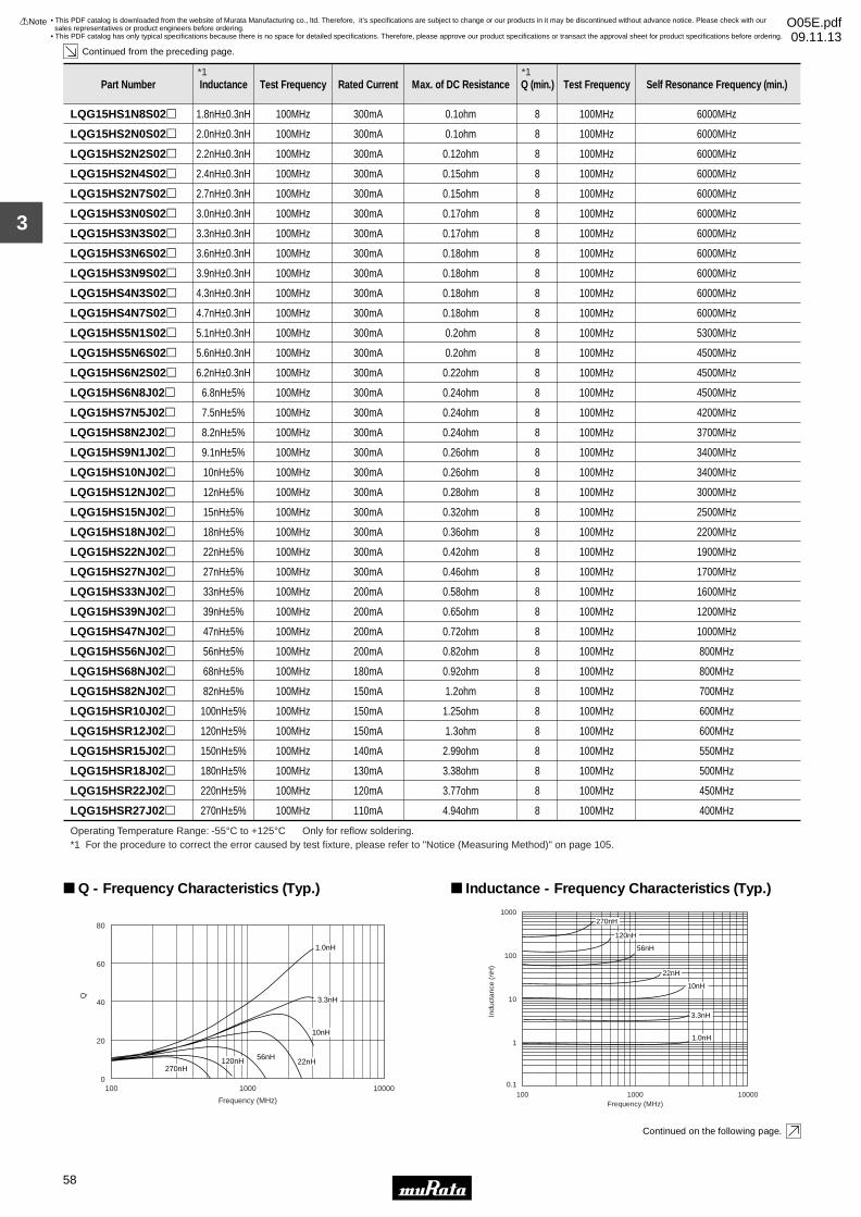
3
!Note • Please read rating and !CAUTION (for storage, operating, rating, soldering, mounting and handling) in this catalog to prevent smoking and/or burning, etc.• This catalog has only typical specifications because there is no space for detailed specifications. Therefore, please approve our product specifications or transact the approval sheet for product specifications before ordering.
58
• This PDF catalog is downloaded from the website of Murata Manufacturing co., ltd. Therefore, it’s specifications are subject to change or our products in it may be discontinued without advance notice. Please check with our sales representatives or product engineers before ordering.
• This PDF catalog has only typical specifications because there is no space for detailed specifications. Therefore, please approve our product specifications or transact the approval sheet for product specifications before ordering.
!Note O05E.pdf09.11.13
LQG15HS2N0S02p 2.0nH±0.3nH 100MHz 300mA 0.1ohm 8 100MHz 6000MHz
LQG15HS2N2S02p 2.2nH±0.3nH 100MHz 300mA 0.12ohm 8 100MHz 6000MHz
LQG15HS2N4S02p 2.4nH±0.3nH 100MHz 300mA 0.15ohm 8 100MHz 6000MHz
LQG15HS2N7S02p 2.7nH±0.3nH 100MHz 300mA 0.15ohm 8 100MHz 6000MHz
LQG15HS3N0S02p 3.0nH±0.3nH 100MHz 300mA 0.17ohm 8 100MHz 6000MHz
LQG15HS3N3S02p 3.3nH±0.3nH 100MHz 300mA 0.17ohm 8 100MHz 6000MHz
LQG15HS3N6S02p 3.6nH±0.3nH 100MHz 300mA 0.18ohm 8 100MHz 6000MHz
LQG15HS3N9S02p 3.9nH±0.3nH 100MHz 300mA 0.18ohm 8 100MHz 6000MHz
LQG15HS4N3S02p 4.3nH±0.3nH 100MHz 300mA 0.18ohm 8 100MHz 6000MHz
LQG15HS4N7S02p 4.7nH±0.3nH 100MHz 300mA 0.18ohm 8 100MHz 6000MHz
LQG15HS5N1S02p 5.1nH±0.3nH 100MHz 300mA 0.2ohm 8 100MHz 5300MHz
LQG15HS5N6S02p 5.6nH±0.3nH 100MHz 300mA 0.2ohm 8 100MHz 4500MHz
LQG15HS6N2S02p 6.2nH±0.3nH 100MHz 300mA 0.22ohm 8 100MHz 4500MHz
LQG15HS6N8J02p 6.8nH±5% 100MHz 300mA 0.24ohm 8 100MHz 4500MHz
LQG15HS7N5J02p 7.5nH±5% 100MHz 300mA 0.24ohm 8 100MHz 4200MHz
LQG15HS8N2J02p 8.2nH±5% 100MHz 300mA 0.24ohm 8 100MHz 3700MHz
Part Number Inductance Test Frequency Rated Current Max. of DC Resistance Q (min.) Test Frequency Self Resonance Frequency (min.)
LQG15HS9N1J02p 9.1nH±5% 100MHz 300mA 0.26ohm 8 100MHz 3400MHz
LQG15HS10NJ02p 10nH±5% 100MHz 300mA 0.26ohm 8 100MHz 3400MHz
LQG15HS12NJ02p 12nH±5% 100MHz 300mA 0.28ohm 8 100MHz 3000MHz
LQG15HS15NJ02p 15nH±5% 100MHz 300mA 0.32ohm 8 100MHz 2500MHz
LQG15HS18NJ02p 18nH±5% 100MHz 300mA 0.36ohm 8 100MHz 2200MHz
LQG15HS22NJ02p 22nH±5% 100MHz 300mA 0.42ohm 8 100MHz 1900MHz
LQG15HS27NJ02p 27nH±5% 100MHz 300mA 0.46ohm 8 100MHz 1700MHz
LQG15HS33NJ02p 33nH±5% 100MHz 200mA 0.58ohm 8 100MHz 1600MHz
LQG15HS39NJ02p 39nH±5% 100MHz 200mA 0.65ohm 8 100MHz 1200MHz
LQG15HS47NJ02p 47nH±5% 100MHz 200mA 0.72ohm 8 100MHz 1000MHz
LQG15HS56NJ02p 56nH±5% 100MHz 200mA 0.82ohm 8 100MHz 800MHz
LQG15HS68NJ02p 68nH±5% 100MHz 180mA 0.92ohm 8 100MHz 800MHz
LQG15HS82NJ02p 82nH±5% 100MHz 150mA 1.2ohm 8 100MHz 700MHz
LQG15HSR10J02p 100nH±5% 100MHz 150mA 1.25ohm 8 100MHz 600MHz
LQG15HSR12J02p 120nH±5% 100MHz 150mA 1.3ohm 8 100MHz 600MHz
LQG15HSR15J02p 150nH±5% 100MHz 140mA 2.99ohm 8 100MHz 550MHz
LQG15HSR18J02p 180nH±5% 100MHz 130mA 3.38ohm 8 100MHz 500MHz
LQG15HSR22J02p 220nH±5% 100MHz 120mA 3.77ohm 8 100MHz 450MHz
LQG15HSR27J02p 270nH±5% 100MHz 110mA 4.94ohm 8 100MHz 400MHz
Operating Temperature Range: -55°C to +125°C Only for reflow soldering.
0
20
40
60
80
100 1000 10000
Frequency (MHz)
Q
120nH
1.0nH
3.3nH
10nH
22nH56nH
270nH
Q - Frequency Characteristics (Typ.)
1
0.1
10
100
1000
100 1000 10000Frequency (MHz)
Indu
ctan
ce (
nH)
E4991A
3.3nH
1.0nH
10nH
22nH
56nH
120nH
270nH
Inductance - Frequency Characteristics (Typ.)
LQG15HS1N8S02p 1.8nH±0.3nH 100MHz 300mA 0.1ohm 8 100MHz 6000MHz
Continued from the preceding page.
Continued on the following page.
*1 For the procedure to correct the error caused by test fixture, please refer to "Notice (Measuring Method)" on page 105.
*1 *1
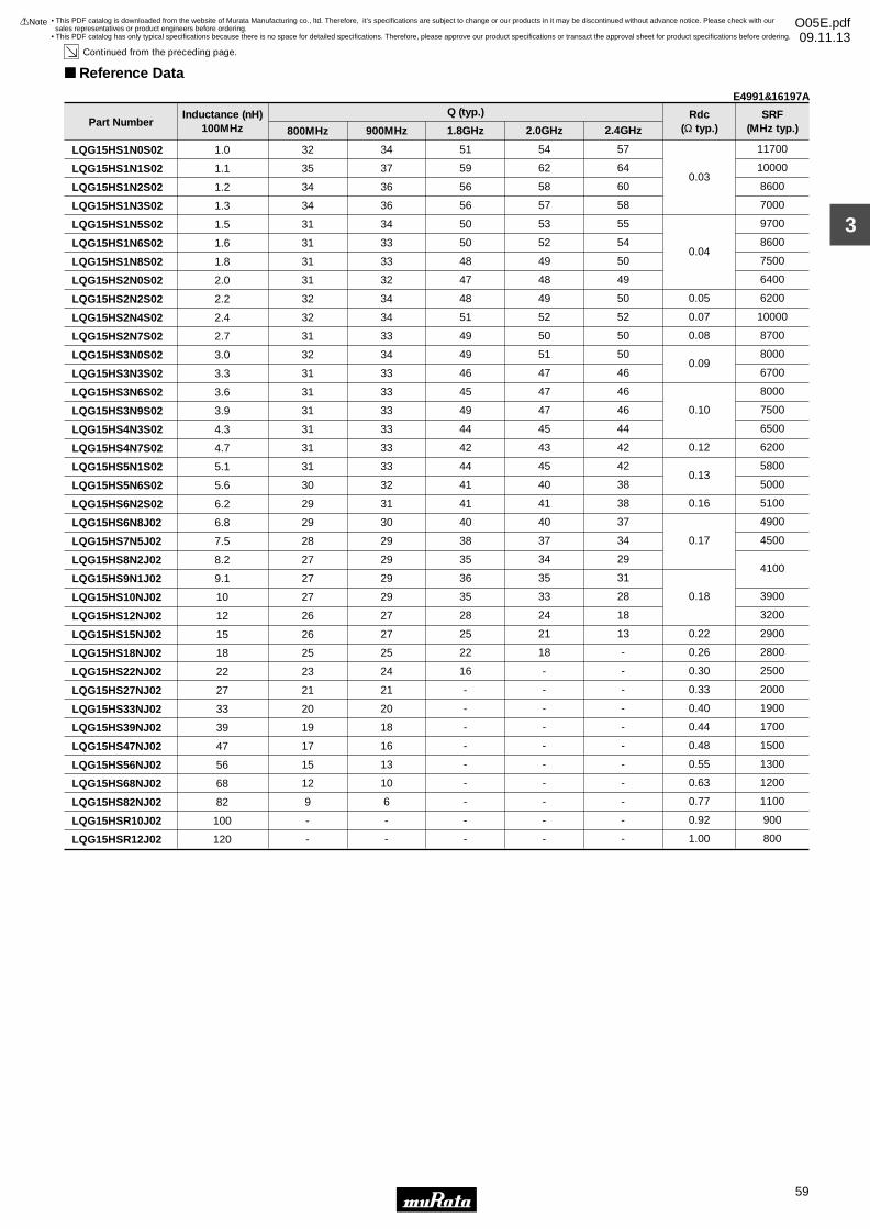
3
!Note • Please read rating and !CAUTION (for storage, operating, rating, soldering, mounting and handling) in this catalog to prevent smoking and/or burning, etc.• This catalog has only typical specifications because there is no space for detailed specifications. Therefore, please approve our product specifications or transact the approval sheet for product specifications before ordering.
59
• This PDF catalog is downloaded from the website of Murata Manufacturing co., ltd. Therefore, it’s specifications are subject to change or our products in it may be discontinued without advance notice. Please check with our sales representatives or product engineers before ordering.
• This PDF catalog has only typical specifications because there is no space for detailed specifications. Therefore, please approve our product specifications or transact the approval sheet for product specifications before ordering.
!Note O05E.pdf09.11.13
Continued from the preceding page.
Reference Data
Part Number
LQG15HS1N0S02
LQG15HS1N1S02
LQG15HS1N2S02
LQG15HS1N3S02
LQG15HS1N5S02
LQG15HS1N6S02
LQG15HS1N8S02
LQG15HS2N0S02
LQG15HS2N2S02
LQG15HS2N4S02
LQG15HS2N7S02
LQG15HS3N0S02
LQG15HS3N3S02
LQG15HS3N6S02
LQG15HS3N9S02
LQG15HS4N3S02
LQG15HS4N7S02
LQG15HS5N1S02
LQG15HS5N6S02
LQG15HS6N2S02
LQG15HS6N8J02
LQG15HS7N5J02
LQG15HS8N2J02
LQG15HS9N1J02
LQG15HS10NJ02
LQG15HS12NJ02
LQG15HS15NJ02
LQG15HS18NJ02
LQG15HS22NJ02
LQG15HS27NJ02
LQG15HS33NJ02
LQG15HS39NJ02
LQG15HS47NJ02
LQG15HS56NJ02
LQG15HS68NJ02
LQG15HS82NJ02
LQG15HSR10J02
LQG15HSR12J02
1.0
1.1
1.2
1.3
1.5
1.6
1.8
2.0
2.2
2.4
2.7
3.0
3.3
3.6
3.9
4.3
4.7
5.1
5.6
6.2
6.8
7.5
8.2
9.1
10
12
15
18
22
27
33
39
47
56
68
82
100
120
Inductance (nH)100MHz
Rdc(Ω typ.)
SRF(MHz typ.)
32
35
34
34
31
31
31
31
32
32
31
32
31
31
31
31
31
31
30
29
29
28
27
27
27
26
26
25
23
21
20
19
17
15
12
9
-
-
800MHz
34
37
36
36
34
33
33
32
34
34
33
34
33
33
33
33
33
33
32
31
30
29
29
29
29
27
27
25
24
21
20
18
16
13
10
6
-
-
900MHz
51
59
56
56
50
50
48
47
48
51
49
49
46
45
49
44
42
44
41
41
40
38
35
36
35
28
25
22
16
-
-
-
-
-
-
-
-
-
1.8GHz
Q (typ.)
54
62
58
57
53
52
49
48
49
52
50
51
47
47
47
45
43
45
40
41
40
37
34
35
33
24
21
18
-
-
-
-
-
-
-
-
-
-
2.0GHz
57
64
60
58
55
54
50
49
50
52
50
50
46
46
46
44
42
42
38
38
37
34
29
31
28
18
13
-
-
-
-
-
-
-
-
-
-
-
2.4GHz
0.03
0.04
0.05
0.07
0.08
0.09
0.10
0.12
0.13
0.16
0.17
0.18
0.22
0.26
0.30
0.33
0.40
0.44
0.48
0.55
0.63
0.77
0.92
1.00
11700
10000
8600
7000
9700
8600
7500
6400
6200
10000
8700
8000
6700
8000
7500
6500
6200
5800
5000
5100
4900
4500
4100
3900
3200
2900
2800
2500
2000
1900
1700
1500
1300
1200
1100
900
800
E4991&16197A
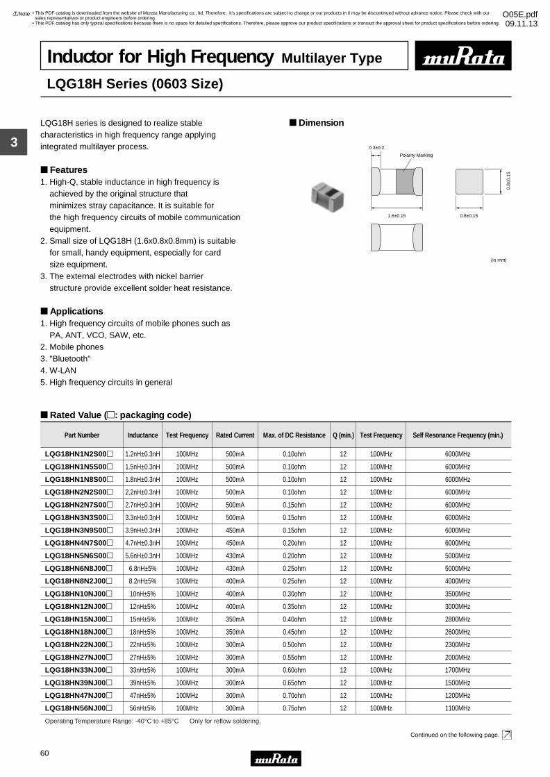
3
!Note • Please read rating and !CAUTION (for storage, operating, rating, soldering, mounting and handling) in this catalog to prevent smoking and/or burning, etc.• This catalog has only typical specifications because there is no space for detailed specifications. Therefore, please approve our product specifications or transact the approval sheet for product specifications before ordering.
60
• This PDF catalog is downloaded from the website of Murata Manufacturing co., ltd. Therefore, it’s specifications are subject to change or our products in it may be discontinued without advance notice. Please check with our sales representatives or product engineers before ordering.
• This PDF catalog has only typical specifications because there is no space for detailed specifications. Therefore, please approve our product specifications or transact the approval sheet for product specifications before ordering.
!Note O05E.pdf09.11.13
Inductor for High Frequency Multilayer Type
LQG18H Series (0603 Size)
LQG18H series is designed to realize stable characteristics in high frequency range applying integrated multilayer process.
Features1. High-Q, stable inductance in high frequency is achieved by the original structure that minimizes stray capacitance. It is suitable for the high frequency circuits of mobile communication equipment.2. Small size of LQG18H (1.6x0.8x0.8mm) is suitable for small, handy equipment, especially for card size equipment.3. The external electrodes with nickel barrier structure provide excellent solder heat resistance.
Applications1. High frequency circuits of mobile phones such as PA, ANT, VCO, SAW, etc.2. Mobile phones3. "Bluetooth"4. W-LAN5. High frequency circuits in general
Dimension
Rated Value (p: packaging code)
Continued on the following page.
1.6±0.15
0.3±0.2
Polarity Marking
0.8±0.15
(in mm)
0.8±
0.15
Part Number Inductance Test Frequency Rated Current Max. of DC Resistance Q (min.) Test Frequency Self Resonance Frequency (min.)
LQG18HN1N2S00p 1.2nH±0.3nH 100MHz 500mA 0.10ohm 12 100MHz 6000MHz
LQG18HN1N5S00p 1.5nH±0.3nH 100MHz 500mA 0.10ohm 12 100MHz 6000MHz
LQG18HN1N8S00p 1.8nH±0.3nH 100MHz 500mA 0.10ohm 12 100MHz 6000MHz
LQG18HN2N2S00p 2.2nH±0.3nH 100MHz 500mA 0.10ohm 12 100MHz 6000MHz
LQG18HN2N7S00p 2.7nH±0.3nH 100MHz 500mA 0.15ohm 12 100MHz 6000MHz
LQG18HN3N3S00p 3.3nH±0.3nH 100MHz 500mA 0.15ohm 12 100MHz 6000MHz
LQG18HN3N9S00p 3.9nH±0.3nH 100MHz 450mA 0.15ohm 12 100MHz 6000MHz
LQG18HN4N7S00p 4.7nH±0.3nH 100MHz 450mA 0.20ohm 12 100MHz 6000MHz
LQG18HN5N6S00p 5.6nH±0.3nH 100MHz 430mA 0.20ohm 12 100MHz 5000MHz
LQG18HN6N8J00p 6.8nH±5% 100MHz 430mA 0.25ohm 12 100MHz 5000MHz
LQG18HN8N2J00p 8.2nH±5% 100MHz 400mA 0.25ohm 12 100MHz 4000MHz
LQG18HN10NJ00p 10nH±5% 100MHz 400mA 0.30ohm 12 100MHz 3500MHz
LQG18HN12NJ00p 12nH±5% 100MHz 400mA 0.35ohm 12 100MHz 3000MHz
LQG18HN15NJ00p 15nH±5% 100MHz 350mA 0.40ohm 12 100MHz 2800MHz
LQG18HN18NJ00p 18nH±5% 100MHz 350mA 0.45ohm 12 100MHz 2600MHz
LQG18HN22NJ00p 22nH±5% 100MHz 300mA 0.50ohm 12 100MHz 2300MHz
LQG18HN27NJ00p 27nH±5% 100MHz 300mA 0.55ohm 12 100MHz 2000MHz
LQG18HN33NJ00p 33nH±5% 100MHz 300mA 0.60ohm 12 100MHz 1700MHz
LQG18HN39NJ00p 39nH±5% 100MHz 300mA 0.65ohm 12 100MHz 1500MHz
LQG18HN47NJ00p 47nH±5% 100MHz 300mA 0.70ohm 12 100MHz 1200MHz
LQG18HN56NJ00p 56nH±5% 100MHz 300mA 0.75ohm 12 100MHz 1100MHz
Operating Temperature Range: -40°C to +85°C Only for reflow soldering.
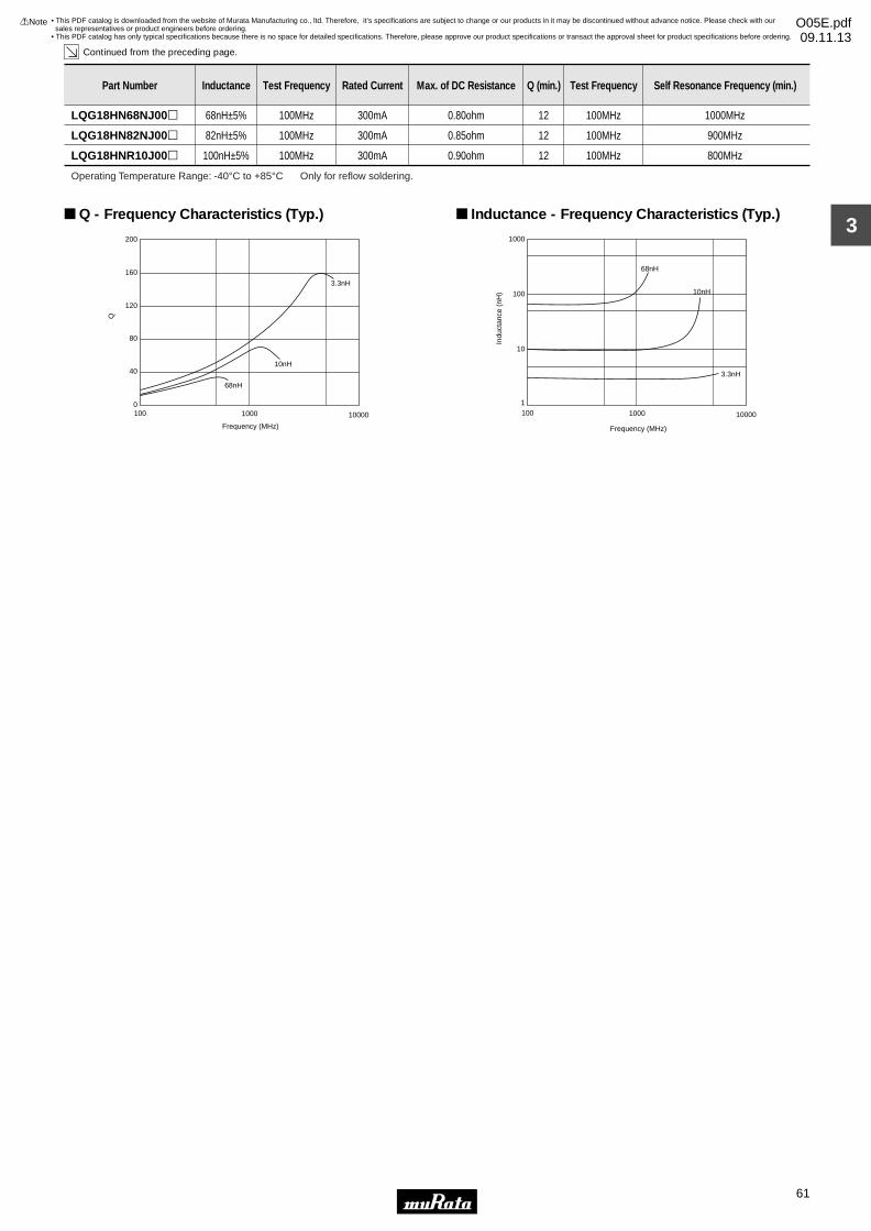
3
!Note • Please read rating and !CAUTION (for storage, operating, rating, soldering, mounting and handling) in this catalog to prevent smoking and/or burning, etc.• This catalog has only typical specifications because there is no space for detailed specifications. Therefore, please approve our product specifications or transact the approval sheet for product specifications before ordering.
61
• This PDF catalog is downloaded from the website of Murata Manufacturing co., ltd. Therefore, it’s specifications are subject to change or our products in it may be discontinued without advance notice. Please check with our sales representatives or product engineers before ordering.
• This PDF catalog has only typical specifications because there is no space for detailed specifications. Therefore, please approve our product specifications or transact the approval sheet for product specifications before ordering.
!Note O05E.pdf09.11.13
Continued from the preceding page.
LQG18HN68NJ00p 68nH±5% 100MHz 300mA 0.80ohm 12 100MHz 1000MHz
LQG18HN82NJ00p 82nH±5% 100MHz 300mA 0.85ohm 12 100MHz 900MHz
Part Number Inductance Test Frequency Rated Current Max. of DC Resistance Q (min.) Test Frequency Self Resonance Frequency (min.)
LQG18HNR10J00p 100nH±5% 100MHz 300mA 0.90ohm 12 100MHz 800MHz
Operating Temperature Range: -40°C to +85°C Only for reflow soldering.
100 1000 10000
Frequency (MHz)
200
160
120
80
40
0
3.3nH
10nH
68nH
Q
Q - Frequency Characteristics (Typ.)
100 1000 10000
1000
100
10
1
68nH
10nH
3.3nH
Frequency (MHz)
Indu
ctan
ce (
nH)
Inductance - Frequency Characteristics (Typ.)
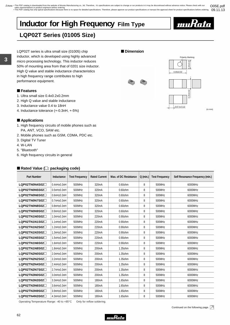
3
!Note • Please read rating and !CAUTION (for storage, operating, rating, soldering, mounting and handling) in this catalog to prevent smoking and/or burning, etc.• This catalog has only typical specifications because there is no space for detailed specifications. Therefore, please approve our product specifications or transact the approval sheet for product specifications before ordering.
62
• This PDF catalog is downloaded from the website of Murata Manufacturing co., ltd. Therefore, it’s specifications are subject to change or our products in it may be discontinued without advance notice. Please check with our sales representatives or product engineers before ordering.
• This PDF catalog has only typical specifications because there is no space for detailed specifications. Therefore, please approve our product specifications or transact the approval sheet for product specifications before ordering.
!Note O05E.pdf09.11.13
Inductor for High Frequency Film Type
LQP02T Series (01005 Size)
LQP02T series is ultra small size (01005) chip inductor, which is developed using highly advanced micro processing technology. This inductor reduces 50% of mounting area from that of 0201 size inductor.High Q value and stable inductance characteristics in high frequency range contributes to high performance equipment.
Features1. Ultra small size 0.4x0.2x0.2mm2. High Q value and stable inductance3. Inductance value 0.4 to 18nH4. Inductance tolerance (+-0.3nH, +-5%)
Applications1. High frequency circuits of mobile phones such as PA, ANT, VCO, SAW etc.2. Mobile phones such as GSM, CDMA, PDC etc.3. Digital TV Tuner4. W-LAN5. "Bluetooth"6. High frequency circuits in general
Dimension
Rated Value (p: packaging code)
Continued on the following page.
(in mm)
0.20
±0.0
2
0.40±0.02
0.20
±0.0
2
0.07 to 0.12
Polarity Marking
Part Number Inductance Test Frequency Rated Current Max. of DC Resistance Q (min.) Test Frequency Self Resonance Frequency (min.)
LQP02TN0N4S02p 0.4nH±0.3nH 500MHz 320mA 0.60ohm 8 500MHz 6000MHz
LQP02TN0N5S02p 0.5nH±0.3nH 500MHz 320mA 0.60ohm 8 500MHz 6000MHz
LQP02TN0N6S02p 0.6nH±0.3nH 500MHz 320mA 0.60ohm 8 500MHz 6000MHz
LQP02TN0N7S02p 0.7nH±0.3nH 500MHz 320mA 0.60ohm 8 500MHz 6000MHz
LQP02TN0N8S02p 0.8nH±0.3nH 500MHz 320mA 0.60ohm 8 500MHz 6000MHz
LQP02TN0N9S02p 0.9nH±0.3nH 500MHz 320mA 0.60ohm 8 500MHz 6000MHz
LQP02TN1N0S02p 1.0nH±0.3nH 500MHz 220mA 0.90ohm 8 500MHz 6000MHz
LQP02TN1N1S02p 1.1nH±0.3nH 500MHz 220mA 0.90ohm 8 500MHz 6000MHz
LQP02TN1N2S02p 1.2nH±0.3nH 500MHz 220mA 0.90ohm 8 500MHz 6000MHz
LQP02TN1N3S02p 1.3nH±0.3nH 500MHz 220mA 0.90ohm 8 500MHz 6000MHz
LQP02TN1N5S02p 1.5nH±0.3nH 500MHz 220mA 0.90ohm 8 500MHz 6000MHz
LQP02TN1N6S02p 1.6nH±0.3nH 500MHz 220mA 0.90ohm 8 500MHz 6000MHz
LQP02TN1N8S02p 1.8nH±0.3nH 500MHz 200mA 1.35ohm 8 500MHz 6000MHz
LQP02TN2N0S02p 2.0nH±0.3nH 500MHz 200mA 1.35ohm 8 500MHz 6000MHz
LQP02TN2N2S02p 2.2nH±0.3nH 500MHz 200mA 1.35ohm 8 500MHz 6000MHz
LQP02TN2N4S02p 2.4nH±0.3nH 500MHz 200mA 1.35ohm 8 500MHz 6000MHz
LQP02TN2N7S02p 2.7nH±0.3nH 500MHz 200mA 1.35ohm 8 500MHz 6000MHz
LQP02TN3N0S02p 3.0nH±0.3nH 500MHz 200mA 1.35ohm 8 500MHz 6000MHz
LQP02TN3N3S02p 3.3nH±0.3nH 500MHz 180mA 1.65ohm 8 500MHz 6000MHz
LQP02TN3N6S02p 3.6nH±0.3nH 500MHz 180mA 1.65ohm 8 500MHz 6000MHz
LQP02TN3N9S02p 3.9nH±0.3nH 500MHz 180mA 1.65ohm 8 500MHz 6000MHz
LQP02TN4N3S02p 4.3nH±0.3nH 500MHz 180mA 1.65ohm 8 500MHz 6000MHz
Operating Temperature Range: -40 to +85°C Only for reflow soldering.
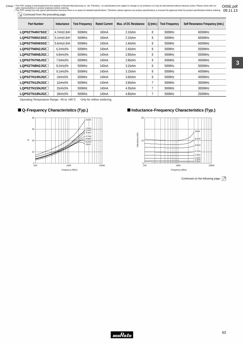
3
!Note • Please read rating and !CAUTION (for storage, operating, rating, soldering, mounting and handling) in this catalog to prevent smoking and/or burning, etc.• This catalog has only typical specifications because there is no space for detailed specifications. Therefore, please approve our product specifications or transact the approval sheet for product specifications before ordering.
63
• This PDF catalog is downloaded from the website of Murata Manufacturing co., ltd. Therefore, it’s specifications are subject to change or our products in it may be discontinued without advance notice. Please check with our sales representatives or product engineers before ordering.
• This PDF catalog has only typical specifications because there is no space for detailed specifications. Therefore, please approve our product specifications or transact the approval sheet for product specifications before ordering.
!Note O05E.pdf09.11.13
Continued from the preceding page.
Continued on the following page.
LQP02TN4N7S02p 4.7nH±0.3nH 500MHz 160mA 2.10ohm 8 500MHz 6000MHz
Part Number Inductance Test Frequency Rated Current Max. of DC Resistance Q (min.) Test Frequency Self Resonance Frequency (min.)
LQP02TN5N1S02p 5.1nH±0.3nH 500MHz 160mA 2.10ohm 8 500MHz 6000MHz
LQP02TN5N6S02p 5.6nH±0.3nH 500MHz 140mA 2.40ohm 8 500MHz 6000MHz
LQP02TN6N2J02p 6.2nH±5% 500MHz 140mA 2.40ohm 8 500MHz 5500MHz
LQP02TN6N8J02p 6.8nH±5% 500MHz 140mA 2.85ohm 8 500MHz 5500MHz
LQP02TN7N5J02p 7.5nH±5% 500MHz 140mA 2.85ohm 8 500MHz 4500MHz
LQP02TN8N2J02p 8.2nH±5% 500MHz 140mA 3.15ohm 8 500MHz 5000MHz
LQP02TN9N1J02p 9.1nH±5% 500MHz 140mA 3.15ohm 8 500MHz 4000MHz
LQP02TN10NJ02p 10nH±5% 500MHz 140mA 3.60ohm 8 500MHz 4000MHz
LQP02TN12NJ02p 12nH±5% 500MHz 140mA 3.90ohm 7 500MHz 3500MHz
LQP02TN15NJ02p 15nH±5% 500MHz 140mA 4.35ohm 7 500MHz 3000MHz
LQP02TN18NJ02p 18nH±5% 500MHz 140mA 4.80ohm 7 500MHz 2500MHz
Operating Temperature Range: -40 to +85°C Only for reflow soldering.
0
10
20
30
40
100001000100
Frequency (MHz)
Q
10nH8.2nH
6.8nH4.7nH
3.3nH2.2nH1.0nH
0.6nH
Q-Frequency Characteristics (Typ.)
0
10
20
100001000100
Frequency (MHz)
Indu
ctan
ce (
nH)
0.6nH1.0nH2.2nH
3.3nH
4.7nH
6.8nH
8.2nH
10nH
Inductance-Frequency Characteristics (Typ.)
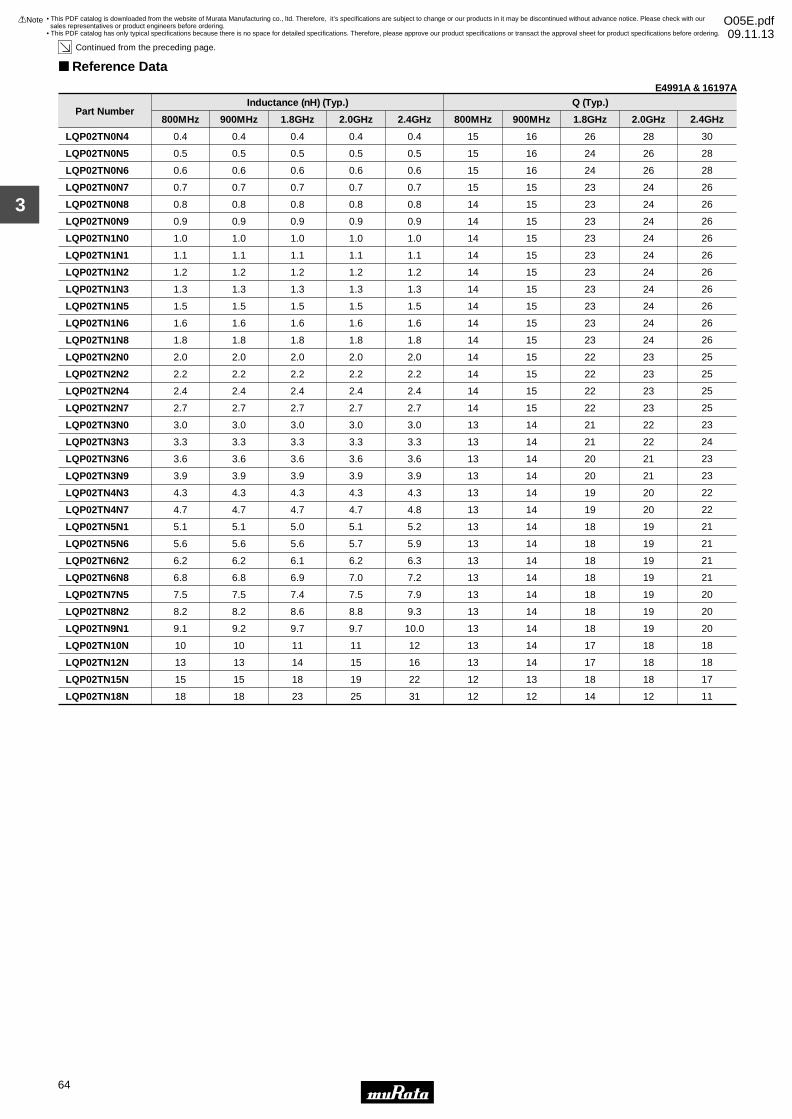
3
!Note • Please read rating and !CAUTION (for storage, operating, rating, soldering, mounting and handling) in this catalog to prevent smoking and/or burning, etc.• This catalog has only typical specifications because there is no space for detailed specifications. Therefore, please approve our product specifications or transact the approval sheet for product specifications before ordering.
64
• This PDF catalog is downloaded from the website of Murata Manufacturing co., ltd. Therefore, it’s specifications are subject to change or our products in it may be discontinued without advance notice. Please check with our sales representatives or product engineers before ordering.
• This PDF catalog has only typical specifications because there is no space for detailed specifications. Therefore, please approve our product specifications or transact the approval sheet for product specifications before ordering.
!Note O05E.pdf09.11.13
Continued from the preceding page.
Reference Data
Part Number
LQP02TN0N4
LQP02TN0N5
LQP02TN0N6
LQP02TN0N7
LQP02TN0N8
LQP02TN0N9
LQP02TN1N0
LQP02TN1N1
LQP02TN1N2
LQP02TN1N3
LQP02TN1N5
LQP02TN1N6
LQP02TN1N8
LQP02TN2N0
LQP02TN2N2
LQP02TN2N4
LQP02TN2N7
LQP02TN3N0
LQP02TN3N3
LQP02TN3N6
LQP02TN3N9
LQP02TN4N3
LQP02TN4N7
LQP02TN5N1
LQP02TN5N6
LQP02TN6N2
LQP02TN6N8
LQP02TN7N5
LQP02TN8N2
LQP02TN9N1
LQP02TN10N
LQP02TN12N
LQP02TN15N
LQP02TN18N
0.4
0.5
0.6
0.7
0.8
0.9
1.0
1.1
1.2
1.3
1.5
1.6
1.8
2.0
2.2
2.4
2.7
3.0
3.3
3.6
3.9
4.3
4.7
5.1
5.6
6.2
6.8
7.5
8.2
9.1
10
13
15
18
800MHz
0.4
0.5
0.6
0.7
0.8
0.9
1.0
1.1
1.2
1.3
1.5
1.6
1.8
2.0
2.2
2.4
2.7
3.0
3.3
3.6
3.9
4.3
4.7
5.1
5.6
6.2
6.8
7.5
8.2
9.2
10
13
15
18
900MHz
0.4
0.5
0.6
0.7
0.8
0.9
1.0
1.1
1.2
1.3
1.5
1.6
1.8
2.0
2.2
2.4
2.7
3.0
3.3
3.6
3.9
4.3
4.7
5.0
5.6
6.1
6.9
7.4
8.6
9.7
11
14
18
23
1.8GHz
0.4
0.5
0.6
0.7
0.8
0.9
1.0
1.1
1.2
1.3
1.5
1.6
1.8
2.0
2.2
2.4
2.7
3.0
3.3
3.6
3.9
4.3
4.7
5.1
5.7
6.2
7.0
7.5
8.8
9.7
11
15
19
25
2.0GHz
0.4
0.5
0.6
0.7
0.8
0.9
1.0
1.1
1.2
1.3
1.5
1.6
1.8
2.0
2.2
2.4
2.7
3.0
3.3
3.6
3.9
4.3
4.8
5.2
5.9
6.3
7.2
7.9
9.3
10.0
12
16
22
31
2.4GHz
15
15
15
15
14
14
14
14
14
14
14
14
14
14
14
14
14
13
13
13
13
13
13
13
13
13
13
13
13
13
13
13
12
12
800MHz
16
16
16
15
15
15
15
15
15
15
15
15
15
15
15
15
15
14
14
14
14
14
14
14
14
14
14
14
14
14
14
14
13
12
900MHz
26
24
24
23
23
23
23
23
23
23
23
23
23
22
22
22
22
21
21
20
20
19
19
18
18
18
18
18
18
18
17
17
18
14
1.8GHz
Inductance (nH) (Typ.) Q (Typ.)
28
26
26
24
24
24
24
24
24
24
24
24
24
23
23
23
23
22
22
21
21
20
20
19
19
19
19
19
19
19
18
18
18
12
2.0GHz
30
28
28
26
26
26
26
26
26
26
26
26
26
25
25
25
25
23
24
23
23
22
22
21
21
21
21
20
20
20
18
18
17
11
2.4GHz
E4991A & 16197A
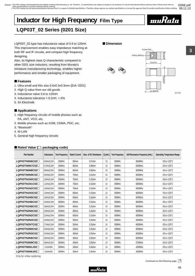
3
!Note • Please read rating and !CAUTION (for storage, operating, rating, soldering, mounting and handling) in this catalog to prevent smoking and/or burning, etc.• This catalog has only typical specifications because there is no space for detailed specifications. Therefore, please approve our product specifications or transact the approval sheet for product specifications before ordering.
65
• This PDF catalog is downloaded from the website of Murata Manufacturing co., ltd. Therefore, it’s specifications are subject to change or our products in it may be discontinued without advance notice. Please check with our sales representatives or product engineers before ordering.
• This PDF catalog has only typical specifications because there is no space for detailed specifications. Therefore, please approve our product specifications or transact the approval sheet for product specifications before ordering.
!Note O05E.pdf09.11.13
Inductor for High Frequency Film Type
LQP03T_02 Series (0201 Size)
LQP03T_02 type has inductance value of 0.6 to 120nH.This improvement enables easy impedance matching at both RF and IF circuits, and compact high frequency designing.Also, its highest class Q characteristic compared to other 0201 size inductors, resulting from Murata's miniature manufacturing technology, enables higher performance and smaller packaging of equipment.
Features 1. Ultra small and thin size 0.6x0.3x0.3mm (EIA: 0201)2. High Q value from our old goods3. Inductance value 0.6 to 120nH4. Inductance tolerance +-0.2nH, +-5%5. Sn Electrode
Applications 1. High frequency circuits of mobile phones such as PA, ANT, VCO, etc.2. Mobile phones such as GSM, CDMA, PDC, etc.3. "Bluetooth"4. W-LAN 5. General high frequency circuits
Dimension
Rated Value (p: packaging code)
Continued on the following page.
0.6±0.03
0.3±
0.03
0.3±
0.03
0.15±0.05(in mm)
Polarity Marking
Colored Side
Part Number Inductance Test Frequency Rated Current Max. of DC Resistance Q (min.) Test Frequency Self Resonance Frequency (min.) Operating Temperature Range
LQP03TN0N6C02p 0.6nH±0.2nH 500MHz 850mA 0.07ohm 14 500MHz 6000MHz -55 to +125°C
LQP03TN0N7C02p 0.7nH±0.2nH 500MHz 800mA 0.08ohm 14 500MHz 6000MHz -55 to +125°C
LQP03TN0N8C02p 0.8nH±0.2nH 500MHz 800mA 0.08ohm 14 500MHz 6000MHz -55 to +125°C
LQP03TN0N9C02p 0.9nH±0.2nH 500MHz 750mA 0.10ohm 14 500MHz 6000MHz -55 to +125°C
LQP03TN1N0C02p 1.0nH±0.2nH 500MHz 750mA 0.10ohm 14 500MHz 6000MHz -55 to +125°C
LQP03TN1N1C02p 1.1nH±0.2nH 500MHz 750mA 0.10ohm 14 500MHz 6000MHz -55 to +125°C
LQP03TN1N2C02p 1.2nH±0.2nH 500MHz 750mA 0.10ohm 14 500MHz 6000MHz -55 to +125°C
LQP03TN1N3C02p 1.3nH±0.2nH 500MHz 600mA 0.15ohm 14 500MHz 6000MHz -55 to +125°C
LQP03TN1N5C02p 1.5nH±0.2nH 500MHz 600mA 0.15ohm 14 500MHz 6000MHz -55 to +125°C
LQP03TN1N6C02p 1.6nH±0.2nH 500MHz 600mA 0.15ohm 14 500MHz 6000MHz -55 to +125°C
LQP03TN1N8C02p 1.8nH±0.2nH 500MHz 600mA 0.15ohm 14 500MHz 6000MHz -55 to +125°C
LQP03TN2N0C02p 2.0nH±0.2nH 500MHz 600mA 0.15ohm 14 500MHz 6000MHz -55 to +125°C
LQP03TN2N2C02p 2.2nH±0.2nH 500MHz 600mA 0.15ohm 14 500MHz 6000MHz -55 to +125°C
LQP03TN2N4C02p 2.4nH±0.2nH 500MHz 500mA 0.20ohm 14 500MHz 6000MHz -55 to +125°C
LQP03TN2N7C02p 2.7nH±0.2nH 500MHz 500mA 0.20ohm 14 500MHz 6000MHz -55 to +125°C
LQP03TN3N0C02p 3.0nH±0.2nH 500MHz 450mA 0.25ohm 14 500MHz 6000MHz -55 to +125°C
LQP03TN3N3C02p 3.3nH±0.2nH 500MHz 450mA 0.25ohm 14 500MHz 6000MHz -55 to +125°C
LQP03TN3N6C02p 3.6nH±0.2nH 500MHz 400mA 0.30ohm 14 500MHz 6000MHz -55 to +125°C
LQP03TN3N9C02p 3.9nH±0.2nH 500MHz 400mA 0.30ohm 14 500MHz 5700MHz -55 to +125°C
Only for reflow soldering.
LQP03TN5N1J02p 5.1nH±5% 500MHz 350mA 0.40ohm 14 500MHz 4200MHz -55 to +125°C
LQP03TN5N6J02p 5.6nH±5% 500MHz 350mA 0.40ohm 14 500MHz 4000MHz -55 to +125°C
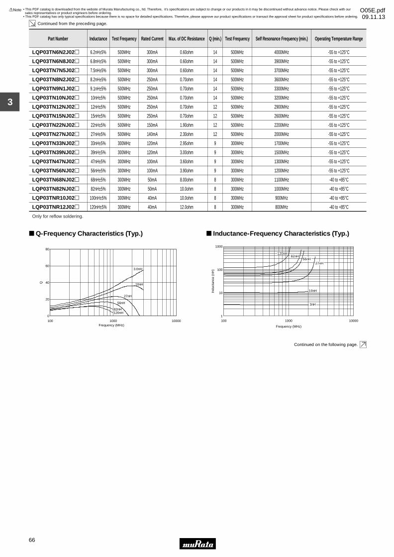
3
!Note • Please read rating and !CAUTION (for storage, operating, rating, soldering, mounting and handling) in this catalog to prevent smoking and/or burning, etc.• This catalog has only typical specifications because there is no space for detailed specifications. Therefore, please approve our product specifications or transact the approval sheet for product specifications before ordering.
66
• This PDF catalog is downloaded from the website of Murata Manufacturing co., ltd. Therefore, it’s specifications are subject to change or our products in it may be discontinued without advance notice. Please check with our sales representatives or product engineers before ordering.
• This PDF catalog has only typical specifications because there is no space for detailed specifications. Therefore, please approve our product specifications or transact the approval sheet for product specifications before ordering.
!Note O05E.pdf09.11.13
Continued from the preceding page.
Continued on the following page.
LQP03TN6N2J02p 6.2nH±5% 500MHz 300mA 0.60ohm 14 500MHz 4000MHz -55 to +125°C
LQP03TN6N8J02p 6.8nH±5% 500MHz 300mA 0.60ohm 14 500MHz 3900MHz -55 to +125°C
LQP03TN7N5J02p 7.5nH±5% 500MHz 300mA 0.60ohm 14 500MHz 3700MHz -55 to +125°C
Part Number Inductance Test Frequency Rated Current Max. of DC Resistance Q (min.) Test Frequency Self Resonance Frequency (min.) Operating Temperature Range
LQP03TN8N2J02p 8.2nH±5% 500MHz 250mA 0.70ohm 14 500MHz 3600MHz -55 to +125°C
LQP03TN9N1J02p 9.1nH±5% 500MHz 250mA 0.70ohm 14 500MHz 3300MHz -55 to +125°C
LQP03TN10NJ02p 10nH±5% 500MHz 250mA 0.70ohm 14 500MHz 3200MHz -55 to +125°C
LQP03TN12NJ02p 12nH±5% 500MHz 250mA 0.70ohm 12 500MHz 2900MHz -55 to +125°C
LQP03TN15NJ02p 15nH±5% 500MHz 250mA 0.70ohm 12 500MHz 2600MHz -55 to +125°C
LQP03TN22NJ02p 22nH±5% 500MHz 150mA 1.90ohm 12 500MHz 2200MHz -55 to +125°C
LQP03TN27NJ02p 27nH±5% 500MHz 140mA 2.30ohm 12 500MHz 2000MHz -55 to +125°C
LQP03TN33NJ02p 33nH±5% 300MHz 120mA 2.95ohm 9 300MHz 1700MHz -55 to +125°C
LQP03TN39NJ02p 39nH±5% 300MHz 120mA 3.00ohm 9 300MHz 1500MHz -55 to +125°C
LQP03TN47NJ02p 47nH±5% 300MHz 100mA 3.60ohm 9 300MHz 1300MHz -55 to +125°C
LQP03TN56NJ02p 56nH±5% 300MHz 100mA 3.90ohm 9 300MHz 1200MHz -55 to +125°C
LQP03TN68NJ02p 68nH±5% 300MHz 50mA 8.00ohm 8 300MHz 1100MHz -40 to +85°C
LQP03TN82NJ02p 82nH±5% 300MHz 50mA 10.0ohm 8 300MHz 1000MHz -40 to +85°C
LQP03TNR10J02p 100nH±5% 300MHz 40mA 10.0ohm 8 300MHz 900MHz -40 to +85°C
LQP03TNR12J02p 120nH±5% 300MHz 40mA 12.0ohm 8 300MHz 800MHz -40 to +85°C
Only for reflow soldering.
0
20
40
60
80
100 1000 10000Frequency (MHz)
Q
120nH82nH
56nH
27nH
3.0nH
10nH
Q-Frequency Characteristics (Typ.)
1
10
100
1000
100 1000 10000
Frequency (MHz)
Indu
ctan
ce (
nH)
10nH
3nH
56nH27nH
82nH120nH
Inductance-Frequency Characteristics (Typ.)

3
!Note • Please read rating and !CAUTION (for storage, operating, rating, soldering, mounting and handling) in this catalog to prevent smoking and/or burning, etc.• This catalog has only typical specifications because there is no space for detailed specifications. Therefore, please approve our product specifications or transact the approval sheet for product specifications before ordering.
67
• This PDF catalog is downloaded from the website of Murata Manufacturing co., ltd. Therefore, it’s specifications are subject to change or our products in it may be discontinued without advance notice. Please check with our sales representatives or product engineers before ordering.
• This PDF catalog has only typical specifications because there is no space for detailed specifications. Therefore, please approve our product specifications or transact the approval sheet for product specifications before ordering.
!Note O05E.pdf09.11.13
Continued from the preceding page.
Reference Data
Part Number
LQP03TN0N6
LQP03TN0N7
LQP03TN0N8
LQP03TN0N9
LQP03TN1N0
LQP03TN1N1
LQP03TN1N2
LQP03TN1N3
LQP03TN1N5
LQP03TN1N6
LQP03TN1N8
LQP03TN2N0
LQP03TN2N2
LQP03TN2N4
LQP03TN2N7
LQP03TN3N0
LQP03TN3N3
LQP03TN3N6
LQP03TN3N9
LQP03TN4N3
LQP03TN4N7
LQP03TN5N1
LQP03TN5N6
LQP03TN6N2
LQP03TN6N8
LQP03TN7N5
LQP03TN8N2
LQP03TN9N1
LQP03TN10N
LQP03TN12N
LQP03TN15N
LQP03TN18N
LQP03TN22N
LQP03TN27N
LQP03TN33N
LQP03TN39N
LQP03TN47N
LQP03TN56N
0.6
0.7
0.8
0.9
1.0
1.1
1.2
1.3
1.5
1.6
1.8
2.0
2.2
2.4
2.7
3.0
3.3
3.6
3.9
4.3
4.7
5.1
5.6
6.2
6.8
7.5
8.2
9.1
10
12
15
18
22
28
35
42
55
63
800MHz
0.6
0.7
0.8
0.9
1.0
1.1
1.2
1.3
1.5
1.6
1.8
2.0
2.2
2.4
2.7
3.0
3.3
3.6
3.9
4.3
4.7
5.1
5.6
6.2
6.8
7.5
8.2
9.1
10
12
15
18
23
29
36
44
58
67
900MHz
0.6
0.7
0.8
0.9
1.0
1.1
1.2
1.3
1.5
1.6
1.8
2.0
2.2
2.4
2.7
3.0
3.3
3.6
3.9
4.3
4.8
5.2
5.8
6.5
7.1
7.9
8.6
9.9
11
13
18
24
32
47
-
-
-
-
1.8GHz
0.6
0.7
0.8
0.9
1.0
1.1
1.2
1.3
1.5
1.6
1.8
2.0
2.2
2.4
2.7
3.0
3.3
3.7
4.0
4.4
4.9
5.3
5.9
6.6
7.4
8.2
9.1
10
12
14
19
-
-
-
-
-
-
-
2.0GHz
0.6
0.7
0.8
0.9
1.0
1.1
1.2
1.3
1.5
1.6
1.8
2.0
2.2
2.4
2.7
3.0
3.4
3.7
4.1
4.5
5.1
5.5
6.1
6.9
7.7
8.7
9.6
11
13
16
23
-
-
-
-
-
-
-
2.4GHz
50 min.
50 min.
50 min.
50 min.
50 min.
50 min.
50
48
45
43
36
38
28
36
28
28
29
31
29
28
28
26
22
20
21
21
18
20
21
21
21
18
16
15
18
15
14
13
800MHz
54 min.
54 min.
54 min.
54 min.
54 min.
54 min.
54
52
48
47
38
40
35
38
30
29
31
33
31
30
30
28
24
21
22
22
19
21
22
22
21
19
17
15
19
15
14
13
900MHz
70 min.
70 min.
70 min.
70 min.
70 min.
70 min.
70
67
63
57
50
52
49
50
40
39
42
43
41
40
40
37
32
27
29
28
25
26
28
27
25
20
16
13
-
-
-
-
1.8GHz
Inductance (nH) (typ.) Q (Typ.)
73 min.
73 min.
73 min.
73 min.
73 min.
73 min.
73
72
66
64
53
54
52
53
42
41
43
45
43
42
42
39
33
28
30
30
25
26
28
27
24
-
-
-
-
-
-
-
2.0GHz
77 min.
77 min.
77 min.
77 min.
77 min.
77 min.
77
74
69
67
55
57
54
56
44
43
45
47
45
44
43
40
33
28
30
29
24
25
27
25
22
-
-
-
-
-
-
-
2.4GHz
E4991A & 16197A

3
!Note • Please read rating and !CAUTION (for storage, operating, rating, soldering, mounting and handling) in this catalog to prevent smoking and/or burning, etc.• This catalog has only typical specifications because there is no space for detailed specifications. Therefore, please approve our product specifications or transact the approval sheet for product specifications before ordering.
68
• This PDF catalog is downloaded from the website of Murata Manufacturing co., ltd. Therefore, it’s specifications are subject to change or our products in it may be discontinued without advance notice. Please check with our sales representatives or product engineers before ordering.
• This PDF catalog has only typical specifications because there is no space for detailed specifications. Therefore, please approve our product specifications or transact the approval sheet for product specifications before ordering.
!Note O05E.pdf09.11.13
Inductor for High Frequency Film Type
LQP03T_00 Series (0201 Size)
LQP03T_00 series offers ultra small size using Murata's miniature manufacturing technology.By this, LQP03T_00 series contributes to miniaturization of equipment.Also, its highest class Q characteristic compared to other Monolithic inductors, enables higher performance of equipment.Furthermore, it enables easy impedance matching at both RF and IF circuits, and compact high frequency circuit designing, because it realizes 0.1nH step at0.6 to 3.9nH and E24 step at 4.3 to 10nH.
Features1. Ultra small size 0.6x0.3x0.3mm2. High Q value in high frequency range3. 0.1nH step 0.6 to 3.9nH: +-0.1nH, +-0.2nH E24 step 4.3 to 10nH: +-3% E12 step 4.7 to 27nH: +-3%, +-5% 33 to 56nH: +-5%4. Sn Electrode
Applications1. High frequency circuits of mobile phones such as PA, ANT, VCO, SAW, etc.2. Mobile phones3. "Bluetooth"4. W-LAN5. High frequency circuits in general
Dimension
Rated Value (p: packaging code)
Continued on the following page.
0.60±0.05
Colored Side
*Inductance: 1.0 to 56nH
0.30
±0.0
50.
30±0
.05
0.15±0.05(in mm)
Colored Side
*Polarity Marking
Part Number Inductance Test Frequency Rated Current Max. of DC Resistance Q (min.) Test Frequency Self Resonance Frequency (min.)
LQP03TN0N6B00p 0.6nH±0.1nH 500MHz 840mA 0.08ohm 13 500MHz 6000MHz
LQP03TN0N6C00p 0.6nH±0.2nH 500MHz 840mA 0.08ohm 13 500MHz 6000MHz
LQP03TN0N7B00p 0.7nH±0.1nH 500MHz 820mA 0.09ohm 13 500MHz 6000MHz
LQP03TN0N8B00p 0.8nH±0.1nH 500MHz 820mA 0.09ohm 13 500MHz 6000MHz
LQP03TN0N8C00p 0.8nH±0.2nH 500MHz 820mA 0.09ohm 13 500MHz 6000MHz
LQP03TN0N9B00p 0.9nH±0.1nH 500MHz 800mA 0.10ohm 13 500MHz 6000MHz
LQP03TN1N0B00p 1.0nH±0.1nH 500MHz 800mA 0.10ohm 13 500MHz 6000MHz
LQP03TN1N0C00p 1.0nH±0.2nH 500MHz 800mA 0.10ohm 13 500MHz 6000MHz
LQP03TN1N1B00p 1.1nH±0.1nH 500MHz 560mA 0.13ohm 13 500MHz 6000MHz
LQP03TN1N2B00p 1.2nH±0.1nH 500MHz 560mA 0.13ohm 13 500MHz 6000MHz
LQP03TN1N2C00p 1.2nH±0.2nH 500MHz 560mA 0.13ohm 13 500MHz 6000MHz
LQP03TN1N3B00p 1.3nH±0.1nH 500MHz 560mA 0.16ohm 13 500MHz 6000MHz
LQP03TN1N4B00p 1.4nH±0.1nH 500MHz 560mA 0.16ohm 13 500MHz 6000MHz
LQP03TN1N5B00p 1.5nH±0.1nH 500MHz 560mA 0.16ohm 13 500MHz 6000MHz
Operating Temperature Range: -40 to +85°C Only for reflow soldering.
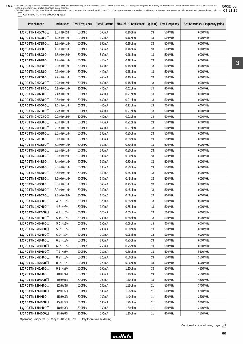
3
!Note • Please read rating and !CAUTION (for storage, operating, rating, soldering, mounting and handling) in this catalog to prevent smoking and/or burning, etc.• This catalog has only typical specifications because there is no space for detailed specifications. Therefore, please approve our product specifications or transact the approval sheet for product specifications before ordering.
69
• This PDF catalog is downloaded from the website of Murata Manufacturing co., ltd. Therefore, it’s specifications are subject to change or our products in it may be discontinued without advance notice. Please check with our sales representatives or product engineers before ordering.
• This PDF catalog has only typical specifications because there is no space for detailed specifications. Therefore, please approve our product specifications or transact the approval sheet for product specifications before ordering.
!Note O05E.pdf09.11.13
Continued from the preceding page.
Continued on the following page.
LQP03TN1N5C00p 1.5nH±0.2nH 500MHz 560mA 0.16ohm 13 500MHz 6000MHz
LQP03TN1N6B00p 1.6nH±0.1nH 500MHz 560mA 0.16ohm 13 500MHz 6000MHz
LQP03TN1N7B00p 1.7nH±0.1nH 500MHz 560mA 0.16ohm 13 500MHz 6000MHz
LQP03TN1N8B00p 1.8nH±0.1nH 500MHz 560mA 0.16ohm 13 500MHz 6000MHz
LQP03TN1N8C00p 1.8nH±0.2nH 500MHz 560mA 0.16ohm 13 500MHz 6000MHz
LQP03TN1N9B00p 1.9nH±0.1nH 500MHz 440mA 0.18ohm 13 500MHz 6000MHz
LQP03TN2N0B00p 2.0nH±0.1nH 500MHz 440mA 0.18ohm 13 500MHz 6000MHz
LQP03TN2N1B00p 2.1nH±0.1nH 500MHz 440mA 0.18ohm 13 500MHz 6000MHz
LQP03TN2N2B00p 2.2nH±0.1nH 500MHz 440mA 0.18ohm 13 500MHz 6000MHz
Part Number Inductance Test Frequency Rated Current Max. of DC Resistance Q (min.) Test Frequency Self Resonance Frequency (min.)
LQP03TN2N2C00p 2.2nH±0.2nH 500MHz 440mA 0.18ohm 13 500MHz 6000MHz
LQP03TN2N3B00p 2.3nH±0.1nH 500MHz 440mA 0.21ohm 13 500MHz 6000MHz
LQP03TN2N4B00p 2.4nH±0.1nH 500MHz 440mA 0.21ohm 13 500MHz 6000MHz
LQP03TN2N5B00p 2.5nH±0.1nH 500MHz 440mA 0.21ohm 13 500MHz 6000MHz
LQP03TN2N6B00p 2.6nH±0.1nH 500MHz 440mA 0.21ohm 13 500MHz 6000MHz
LQP03TN2N7B00p 2.7nH±0.1nH 500MHz 440mA 0.21ohm 13 500MHz 6000MHz
LQP03TN2N7C00p 2.7nH±0.2nH 500MHz 440mA 0.21ohm 13 500MHz 6000MHz
LQP03TN2N8B00p 2.8nH±0.1nH 500MHz 440mA 0.21ohm 13 500MHz 6000MHz
LQP03TN2N9B00p 2.9nH±0.1nH 500MHz 440mA 0.21ohm 13 500MHz 6000MHz
LQP03TN3N0B00p 3.0nH±0.1nH 500MHz 380mA 0.30ohm 13 500MHz 6000MHz
LQP03TN3N1B00p 3.1nH±0.1nH 500MHz 380mA 0.30ohm 13 500MHz 6000MHz
LQP03TN3N2B00p 3.2nH±0.1nH 500MHz 380mA 0.30ohm 13 500MHz 6000MHz
LQP03TN3N3B00p 3.3nH±0.1nH 500MHz 380mA 0.30ohm 13 500MHz 6000MHz
LQP03TN3N3C00p 3.3nH±0.2nH 500MHz 380mA 0.30ohm 13 500MHz 6000MHz
LQP03TN3N4B00p 3.4nH±0.1nH 500MHz 380mA 0.30ohm 13 500MHz 6000MHz
LQP03TN3N5B00p 3.5nH±0.1nH 500MHz 380mA 0.30ohm 13 500MHz 6000MHz
LQP03TN3N6B00p 3.6nH±0.1nH 500MHz 340mA 0.45ohm 13 500MHz 6000MHz
LQP03TN3N7B00p 3.7nH±0.1nH 500MHz 340mA 0.45ohm 13 500MHz 6000MHz
LQP03TN3N8B00p 3.8nH±0.1nH 500MHz 340mA 0.45ohm 13 500MHz 6000MHz
LQP03TN3N9B00p 3.9nH±0.1nH 500MHz 340mA 0.45ohm 13 500MHz 6000MHz
LQP03TN3N9C00p 3.9nH±0.2nH 500MHz 340mA 0.45ohm 13 500MHz 6000MHz
LQP03TN4N3H00p 4.3nH±3% 500MHz 320mA 0.55ohm 13 500MHz 6000MHz
LQP03TN4N7H00p 4.7nH±3% 500MHz 320mA 0.55ohm 13 500MHz 6000MHz
LQP03TN4N7J00p 4.7nH±5% 500MHz 320mA 0.55ohm 13 500MHz 6000MHz
LQP03TN5N1H00p 5.1nH±3% 500MHz 280mA 0.68ohm 13 500MHz 6000MHz
LQP03TN5N6H00p 5.6nH±3% 500MHz 280mA 0.68ohm 13 500MHz 6000MHz
LQP03TN5N6J00p 5.6nH±5% 500MHz 280mA 0.68ohm 13 500MHz 6000MHz
LQP03TN6N2H00p 6.2nH±3% 500MHz 260mA 0.75ohm 13 500MHz 6000MHz
LQP03TN6N8H00p 6.8nH±3% 500MHz 260mA 0.75ohm 13 500MHz 6000MHz
LQP03TN6N8J00p 6.8nH±5% 500MHz 260mA 0.75ohm 13 500MHz 6000MHz
LQP03TN7N5H00p 7.5nH±3% 500MHz 220mA 0.86ohm 13 500MHz 5500MHz
LQP03TN8N2H00p 8.2nH±3% 500MHz 220mA 0.86ohm 13 500MHz 5500MHz
LQP03TN8N2J00p 8.2nH±5% 500MHz 220mA 0.86ohm 13 500MHz 5500MHz
LQP03TN9N1H00p 9.1nH±3% 500MHz 200mA 1.10ohm 13 500MHz 4500MHz
LQP03TN10NH00p 10nH±3% 500MHz 200mA 1.10ohm 13 500MHz 4500MHz
LQP03TN10NJ00p 10nH±5% 500MHz 200mA 1.10ohm 13 500MHz 4500MHz
LQP03TN12NH00p 12nH±3% 500MHz 180mA 1.25ohm 11 500MHz 3700MHz
LQP03TN12NJ00p 12nH±5% 500MHz 180mA 1.25ohm 11 500MHz 3700MHz
LQP03TN15NH00p 15nH±3% 500MHz 180mA 1.40ohm 11 500MHz 3300MHz
LQP03TN15NJ00p 15nH±5% 500MHz 180mA 1.40ohm 11 500MHz 3300MHz
LQP03TN18NH00p 18nH±3% 500MHz 160mA 1.60ohm 11 500MHz 3100MHz
Operating Temperature Range: -40 to +85°C Only for reflow soldering.
LQP03TN18NJ00p 18nH±5% 500MHz 160mA 1.60ohm 11 500MHz 3100MHz
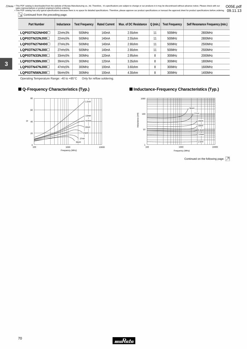
3
!Note • Please read rating and !CAUTION (for storage, operating, rating, soldering, mounting and handling) in this catalog to prevent smoking and/or burning, etc.• This catalog has only typical specifications because there is no space for detailed specifications. Therefore, please approve our product specifications or transact the approval sheet for product specifications before ordering.
70
• This PDF catalog is downloaded from the website of Murata Manufacturing co., ltd. Therefore, it’s specifications are subject to change or our products in it may be discontinued without advance notice. Please check with our sales representatives or product engineers before ordering.
• This PDF catalog has only typical specifications because there is no space for detailed specifications. Therefore, please approve our product specifications or transact the approval sheet for product specifications before ordering.
!Note O05E.pdf09.11.13
Continued from the preceding page.
Continued on the following page.
Part Number Inductance Test Frequency Rated Current Max. of DC Resistance Q (min.) Test Frequency Self Resonance Frequency (min.)
LQP03TN22NH00p 22nH±3% 500MHz 140mA 2.55ohm 11 500MHz 2800MHz
LQP03TN22NJ00p 22nH±5% 500MHz 140mA 2.55ohm 11 500MHz 2800MHz
LQP03TN27NH00p 27nH±3% 500MHz 140mA 2.90ohm 11 500MHz 2500MHz
LQP03TN27NJ00p 27nH±5% 500MHz 140mA 2.90ohm 11 500MHz 2500MHz
LQP03TN33NJ00p 33nH±5% 300MHz 120mA 2.95ohm 8 300MHz 2000MHz
LQP03TN39NJ00p 39nH±5% 300MHz 120mA 3.35ohm 8 300MHz 1800MHz
LQP03TN47NJ00p 47nH±5% 300MHz 100mA 3.60ohm 8 300MHz 1600MHz
LQP03TN56NJ00p 56nH±5% 300MHz 100mA 4.30ohm 8 300MHz 1400MHz
Operating Temperature Range: -40 to +85°C Only for reflow soldering.
100 1000 10000
20
40
60
80
0
Q
Frequency (MHz)
E4991A 16197A
1.5nH
3.9nH
6.8nH
10nH
15nH
27nH
56nH
Q-Frequency Characteristics (Typ.)
1
10
100
1000
100 1000 10000
Frequency (MHz)
Indu
ctan
ce (
nH)
E4991A 16197A
1.5nH
3.9nH
6.8nH
10nH
15nH
27nH
56nH
Inductance-Frequency Characteristics (Typ.)
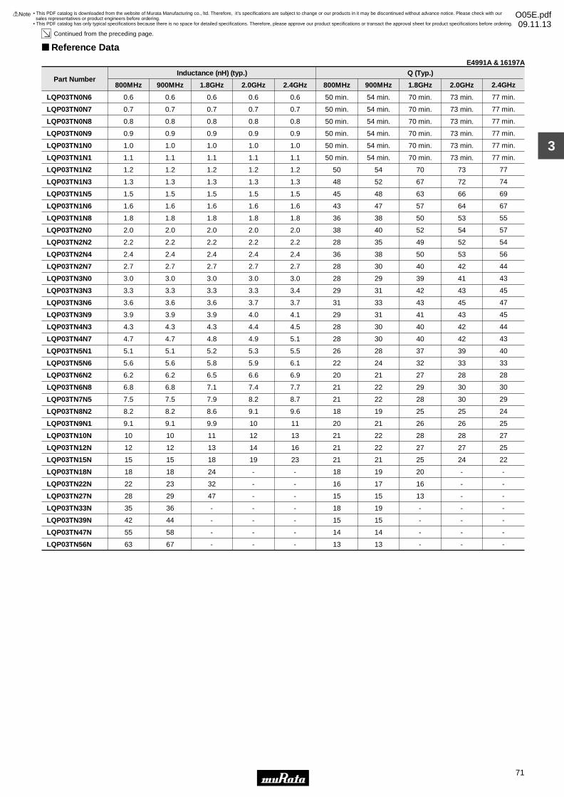
3
!Note • Please read rating and !CAUTION (for storage, operating, rating, soldering, mounting and handling) in this catalog to prevent smoking and/or burning, etc.• This catalog has only typical specifications because there is no space for detailed specifications. Therefore, please approve our product specifications or transact the approval sheet for product specifications before ordering.
71
• This PDF catalog is downloaded from the website of Murata Manufacturing co., ltd. Therefore, it’s specifications are subject to change or our products in it may be discontinued without advance notice. Please check with our sales representatives or product engineers before ordering.
• This PDF catalog has only typical specifications because there is no space for detailed specifications. Therefore, please approve our product specifications or transact the approval sheet for product specifications before ordering.
!Note O05E.pdf09.11.13
Continued from the preceding page.
Reference Data
Part Number
LQP03TN0N6
LQP03TN0N7
LQP03TN0N8
LQP03TN0N9
LQP03TN1N0
LQP03TN1N1
LQP03TN1N2
LQP03TN1N3
LQP03TN1N5
LQP03TN1N6
LQP03TN1N8
LQP03TN2N0
LQP03TN2N2
LQP03TN2N4
LQP03TN2N7
LQP03TN3N0
LQP03TN3N3
LQP03TN3N6
LQP03TN3N9
LQP03TN4N3
LQP03TN4N7
LQP03TN5N1
LQP03TN5N6
LQP03TN6N2
LQP03TN6N8
LQP03TN7N5
LQP03TN8N2
LQP03TN9N1
LQP03TN10N
LQP03TN12N
LQP03TN15N
LQP03TN18N
LQP03TN22N
LQP03TN27N
LQP03TN33N
LQP03TN39N
LQP03TN47N
LQP03TN56N
0.6
0.7
0.8
0.9
1.0
1.1
1.2
1.3
1.5
1.6
1.8
2.0
2.2
2.4
2.7
3.0
3.3
3.6
3.9
4.3
4.7
5.1
5.6
6.2
6.8
7.5
8.2
9.1
10
12
15
18
22
28
35
42
55
63
800MHz
0.6
0.7
0.8
0.9
1.0
1.1
1.2
1.3
1.5
1.6
1.8
2.0
2.2
2.4
2.7
3.0
3.3
3.6
3.9
4.3
4.7
5.1
5.6
6.2
6.8
7.5
8.2
9.1
10
12
15
18
23
29
36
44
58
67
900MHz
0.6
0.7
0.8
0.9
1.0
1.1
1.2
1.3
1.5
1.6
1.8
2.0
2.2
2.4
2.7
3.0
3.3
3.6
3.9
4.3
4.8
5.2
5.8
6.5
7.1
7.9
8.6
9.9
11
13
18
24
32
47
-
-
-
-
1.8GHz
0.6
0.7
0.8
0.9
1.0
1.1
1.2
1.3
1.5
1.6
1.8
2.0
2.2
2.4
2.7
3.0
3.3
3.7
4.0
4.4
4.9
5.3
5.9
6.6
7.4
8.2
9.1
10
12
14
19
-
-
-
-
-
-
-
2.0GHz
0.6
0.7
0.8
0.9
1.0
1.1
1.2
1.3
1.5
1.6
1.8
2.0
2.2
2.4
2.7
3.0
3.4
3.7
4.1
4.5
5.1
5.5
6.1
6.9
7.7
8.7
9.6
11
13
16
23
-
-
-
-
-
-
-
2.4GHz
50 min.
50 min.
50 min.
50 min.
50 min.
50 min.
50
48
45
43
36
38
28
36
28
28
29
31
29
28
28
26
22
20
21
21
18
20
21
21
21
18
16
15
18
15
14
13
800MHz
54 min.
54 min.
54 min.
54 min.
54 min.
54 min.
54
52
48
47
38
40
35
38
30
29
31
33
31
30
30
28
24
21
22
22
19
21
22
22
21
19
17
15
19
15
14
13
900MHz
70 min.
70 min.
70 min.
70 min.
70 min.
70 min.
70
67
63
57
50
52
49
50
40
39
42
43
41
40
40
37
32
27
29
28
25
26
28
27
25
20
16
13
-
-
-
-
1.8GHz
Inductance (nH) (typ.) Q (Typ.)
73 min.
73 min.
73 min.
73 min.
73 min.
73 min.
73
72
66
64
53
54
52
53
42
41
43
45
43
42
42
39
33
28
30
30
25
26
28
27
24
-
-
-
-
-
-
-
2.0GHz
77 min.
77 min.
77 min.
77 min.
77 min.
77 min.
77
74
69
67
55
57
54
56
44
43
45
47
45
44
43
40
33
28
30
29
24
25
27
25
22
-
-
-
-
-
-
-
2.4GHz
E4991A & 16197A
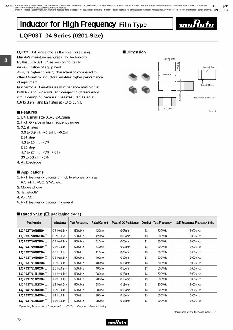
3
!Note • Please read rating and !CAUTION (for storage, operating, rating, soldering, mounting and handling) in this catalog to prevent smoking and/or burning, etc.• This catalog has only typical specifications because there is no space for detailed specifications. Therefore, please approve our product specifications or transact the approval sheet for product specifications before ordering.
72
• This PDF catalog is downloaded from the website of Murata Manufacturing co., ltd. Therefore, it’s specifications are subject to change or our products in it may be discontinued without advance notice. Please check with our sales representatives or product engineers before ordering.
• This PDF catalog has only typical specifications because there is no space for detailed specifications. Therefore, please approve our product specifications or transact the approval sheet for product specifications before ordering.
!Note O05E.pdf09.11.13
Inductor for High Frequency Film Type
LQP03T_04 Series (0201 Size)
LQP03T_04 series offers ultra small size using Murata's miniature manufacturing technology.By this, LQP03T_04 series contributes to miniaturization of equipment.Also, its highest class Q characteristic compared to other Monolithic inductors, enables higher performance of equipment.Furthermore, it enables easy impedance matching at both RF and IF circuits, and compact high frequency circuit designing because it realizes 0.1nH step at0.6 to 3.9nH and E24 step at 4.3 to 10nH.
Features1. Ultra small size 0.6x0.3x0.3mm2. High Q value in high frequency range3. 0.1nH step 0.6 to 3.9nH: +-0.1nH, +-0.2nH E24 step 4.3 to 10nH: +-3% E12 step 4.7 to 27nH: +-3%, +-5% 33 to 56nH: +-5%4. Au Electrode
Applications1. High frequency circuits of mobile phones such as PA, ANT, VCO, SAW, etc.2. Mobile phone 3. "Bluetooth"4. W-LAN5. High frequency circuits in general
Dimension
Rated Value (p: packaging code)
Continued on the following page.
0.60±0.05
Colored Side
*Inductance: 1.0 to 56nH
0.30
±0.0
50.
30±0
.05
0.15±0.05(in mm)
Colored Side
*Polarity Marking
Part Number Inductance Test Frequency Rated Current Max. of DC Resistance Q (min.) Test Frequency Self Resonance Frequency (min.)
LQP03TN0N6B04p 0.6nH±0.1nH 500MHz 420mA 0.08ohm 13 500MHz 6000MHz
LQP03TN0N6C04p 0.6nH±0.2nH 500MHz 420mA 0.08ohm 13 500MHz 6000MHz
LQP03TN0N7B04p 0.7nH±0.1nH 500MHz 410mA 0.09ohm 13 500MHz 6000MHz
LQP03TN0N8B04p 0.8nH±0.1nH 500MHz 410mA 0.09ohm 13 500MHz 6000MHz
LQP03TN0N8C04p 0.8nH±0.2nH 500MHz 410mA 0.09ohm 13 500MHz 6000MHz
LQP03TN0N9B04p 0.9nH±0.1nH 500MHz 400mA 0.10ohm 13 500MHz 6000MHz
LQP03TN1N0B04p 1.0nH±0.1nH 500MHz 400mA 0.10ohm 13 500MHz 6000MHz
LQP03TN1N0C04p 1.0nH±0.2nH 500MHz 400mA 0.10ohm 13 500MHz 6000MHz
LQP03TN1N1B04p 1.1nH±0.1nH 500MHz 280mA 0.13ohm 13 500MHz 6000MHz
LQP03TN1N2B04p 1.2nH±0.1nH 500MHz 280mA 0.13ohm 13 500MHz 6000MHz
LQP03TN1N2C04p 1.2nH±0.2nH 500MHz 280mA 0.13ohm 13 500MHz 6000MHz
LQP03TN1N3B04p 1.3nH±0.1nH 500MHz 280mA 0.16ohm 13 500MHz 6000MHz
LQP03TN1N4B04p 1.4nH±0.1nH 500MHz 280mA 0.16ohm 13 500MHz 6000MHz
LQP03TN1N5B04p 1.5nH±0.1nH 500MHz 280mA 0.16ohm 13 500MHz 6000MHz
Operating Temperature Range: -40 to +85°C Only for reflow soldering.

3
!Note • Please read rating and !CAUTION (for storage, operating, rating, soldering, mounting and handling) in this catalog to prevent smoking and/or burning, etc.• This catalog has only typical specifications because there is no space for detailed specifications. Therefore, please approve our product specifications or transact the approval sheet for product specifications before ordering.
73
• This PDF catalog is downloaded from the website of Murata Manufacturing co., ltd. Therefore, it’s specifications are subject to change or our products in it may be discontinued without advance notice. Please check with our sales representatives or product engineers before ordering.
• This PDF catalog has only typical specifications because there is no space for detailed specifications. Therefore, please approve our product specifications or transact the approval sheet for product specifications before ordering.
!Note O05E.pdf09.11.13
Continued from the preceding page.
Continued on the following page.
LQP03TN1N5C04p 1.5nH±0.2nH 500MHz 280mA 0.16ohm 13 500MHz 6000MHz
LQP03TN1N6B04p 1.6nH±0.1nH 500MHz 280mA 0.16ohm 13 500MHz 6000MHz
LQP03TN1N7B04p 1.7nH±0.1nH 500MHz 280mA 0.16ohm 13 500MHz 6000MHz
LQP03TN1N8B04p 1.8nH±0.1nH 500MHz 280mA 0.16ohm 13 500MHz 6000MHz
LQP03TN1N8C04p 1.8nH±0.2nH 500MHz 280mA 0.16ohm 13 500MHz 6000MHz
LQP03TN1N9B04p 1.9nH±0.1nH 500MHz 220mA 0.18ohm 13 500MHz 6000MHz
LQP03TN2N0B04p 2.0nH±0.1nH 500MHz 220mA 0.18ohm 13 500MHz 6000MHz
LQP03TN2N1B04p 2.1nH±0.1nH 500MHz 220mA 0.18ohm 13 500MHz 6000MHz
LQP03TN2N2B04p 2.2nH±0.1nH 500MHz 220mA 0.18ohm 13 500MHz 6000MHz
Part Number Inductance Test Frequency Rated Current Max. of DC Resistance Q (min.) Test Frequency Self Resonance Frequency (min.)
LQP03TN2N2C04p 2.2nH±0.2nH 500MHz 220mA 0.18ohm 13 500MHz 6000MHz
LQP03TN2N3B04p 2.3nH±0.1nH 500MHz 220mA 0.20ohm 13 500MHz 6000MHz
LQP03TN2N4B04p 2.4nH±0.1nH 500MHz 220mA 0.20ohm 13 500MHz 6000MHz
LQP03TN2N5B04p 2.5nH±0.1nH 500MHz 220mA 0.20ohm 13 500MHz 6000MHz
LQP03TN2N6B04p 2.6nH±0.1nH 500MHz 220mA 0.20ohm 13 500MHz 6000MHz
LQP03TN2N7B04p 2.7nH±0.1nH 500MHz 220mA 0.20ohm 13 500MHz 6000MHz
LQP03TN2N7C04p 2.7nH±0.2nH 500MHz 220mA 0.20ohm 13 500MHz 6000MHz
LQP03TN2N8B04p 2.8nH±0.1nH 500MHz 220mA 0.20ohm 13 500MHz 6000MHz
LQP03TN2N9B04p 2.9nH±0.1nH 500MHz 220mA 0.20ohm 13 500MHz 6000MHz
LQP03TN3N0B04p 3.0nH±0.1nH 500MHz 190mA 0.20ohm 13 500MHz 6000MHz
LQP03TN3N1B04p 3.1nH±0.1nH 500MHz 190mA 0.20ohm 13 500MHz 6000MHz
LQP03TN3N2B04p 3.2nH±0.1nH 500MHz 190mA 0.20ohm 13 500MHz 6000MHz
LQP03TN3N3B04p 3.3nH±0.1nH 500MHz 190mA 0.20ohm 13 500MHz 6000MHz
LQP03TN3N3C04p 3.3nH±0.2nH 500MHz 190mA 0.20ohm 13 500MHz 6000MHz
LQP03TN3N4B04p 3.4nH±0.1nH 500MHz 190mA 0.30ohm 13 500MHz 6000MHz
LQP03TN3N5B04p 3.5nH±0.1nH 500MHz 190mA 0.30ohm 13 500MHz 6000MHz
LQP03TN3N6B04p 3.6nH±0.1nH 500MHz 170mA 0.30ohm 13 500MHz 6000MHz
LQP03TN3N7B04p 3.7nH±0.1nH 500MHz 170mA 0.30ohm 13 500MHz 6000MHz
LQP03TN3N8B04p 3.8nH±0.1nH 500MHz 170mA 0.30ohm 13 500MHz 6000MHz
LQP03TN3N9B04p 3.9nH±0.1nH 500MHz 170mA 0.30ohm 13 500MHz 6000MHz
LQP03TN3N9C04p 3.9nH±0.2nH 500MHz 170mA 0.30ohm 13 500MHz 6000MHz
LQP03TN4N3H04p 4.3nH±3% 500MHz 160mA 0.40ohm 13 500MHz 6000MHz
LQP03TN4N7H04p 4.7nH±3% 500MHz 160mA 0.40ohm 13 500MHz 6000MHz
LQP03TN4N7J04p 4.7nH±5% 500MHz 160mA 0.40ohm 13 500MHz 6000MHz
LQP03TN5N1H04p 5.1nH±3% 500MHz 140mA 0.55ohm 13 500MHz 6000MHz
LQP03TN5N6H04p 5.6nH±3% 500MHz 140mA 0.55ohm 13 500MHz 6000MHz
LQP03TN5N6J04p 5.6nH±5% 500MHz 140mA 0.55ohm 13 500MHz 6000MHz
LQP03TN6N2H04p 6.2nH±3% 500MHz 130mA 0.60ohm 13 500MHz 6000MHz
LQP03TN6N2J04p 6.2nH±5% 500MHz 130mA 0.60ohm 13 500MHz 6000MHz
LQP03TN6N8H04p 6.8nH±3% 500MHz 130mA 0.60ohm 13 500MHz 6000MHz
LQP03TN6N8J04p 6.8nH±5% 500MHz 130mA 0.60ohm 13 500MHz 6000MHz
LQP03TN7N5H04p 7.5nH±3% 500MHz 110mA 0.65ohm 13 500MHz 5500MHz
LQP03TN7N5J04p 7.5nH±5% 500MHz 110mA 0.65ohm 13 500MHz 5500MHz
LQP03TN8N2H04p 8.2nH±3% 500MHz 110mA 0.86ohm 13 500MHz 5500MHz
LQP03TN8N2J04p 8.2nH±5% 500MHz 110mA 0.86ohm 13 500MHz 5500MHz
LQP03TN9N1H04p 9.1nH±3% 500MHz 100mA 1.10ohm 13 500MHz 4500MHz
LQP03TN9N1J04p 9.1nH±5% 500MHz 100mA 1.10ohm 13 500MHz 4500MHz
LQP03TN10NH04p 10nH±3% 500MHz 100mA 1.10ohm 13 500MHz 4500MHz
LQP03TN10NJ04p 10nH±5% 500MHz 100mA 1.10ohm 13 500MHz 4500MHz
LQP03TN12NH04p 12nH±3% 500MHz 90mA 1.15ohm 11 500MHz 3700MHz
LQP03TN12NJ04p 12nH±5% 500MHz 90mA 1.15ohm 11 500MHz 3700MHz
Operating Temperature Range: -40 to +85°C Only for reflow soldering.
LQP03TN15NH04p 15nH±3% 500MHz 90mA 1.40ohm 11 500MHz 3300MHz
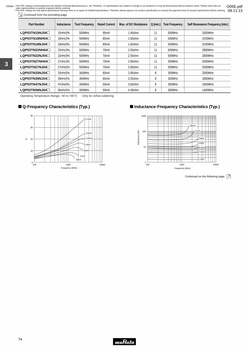
3
!Note • Please read rating and !CAUTION (for storage, operating, rating, soldering, mounting and handling) in this catalog to prevent smoking and/or burning, etc.• This catalog has only typical specifications because there is no space for detailed specifications. Therefore, please approve our product specifications or transact the approval sheet for product specifications before ordering.
74
• This PDF catalog is downloaded from the website of Murata Manufacturing co., ltd. Therefore, it’s specifications are subject to change or our products in it may be discontinued without advance notice. Please check with our sales representatives or product engineers before ordering.
• This PDF catalog has only typical specifications because there is no space for detailed specifications. Therefore, please approve our product specifications or transact the approval sheet for product specifications before ordering.
!Note O05E.pdf09.11.13
Continued from the preceding page.
Continued on the following page.
Part Number Inductance Test Frequency Rated Current Max. of DC Resistance Q (min.) Test Frequency Self Resonance Frequency (min.)
LQP03TN15NJ04p 15nH±5% 500MHz 90mA 1.40ohm 11 500MHz 3300MHz
LQP03TN18NH04p 18nH±3% 500MHz 80mA 1.60ohm 11 500MHz 3100MHz
LQP03TN18NJ04p 18nH±5% 500MHz 80mA 1.60ohm 11 500MHz 3100MHz
LQP03TN22NH04p 22nH±3% 500MHz 70mA 2.55ohm 11 500MHz 2800MHz
LQP03TN22NJ04p 22nH±5% 500MHz 70mA 2.55ohm 11 500MHz 2800MHz
LQP03TN27NH04p 27nH±3% 500MHz 70mA 2.90ohm 11 500MHz 2500MHz
LQP03TN27NJ04p 27nH±5% 500MHz 70mA 2.90ohm 11 500MHz 2500MHz
LQP03TN33NJ04p 33nH±5% 300MHz 60mA 2.95ohm 8 300MHz 2000MHz
LQP03TN39NJ04p 39nH±5% 300MHz 60mA 3.35ohm 8 300MHz 1800MHz
LQP03TN47NJ04p 47nH±5% 300MHz 50mA 3.60ohm 8 300MHz 1600MHz
LQP03TN56NJ04p 56nH±5% 300MHz 50mA 4.30ohm 8 300MHz 1400MHz
Operating Temperature Range: -40 to +85°C Only for reflow soldering.
100 1000 10000
20
40
60
80
0
Q
Frequency (MHz)
E4991A 16197A
1.5nH
3.9nH
6.8nH
10nH
15nH
27nH
56nH
Q-Frequency Characteristics (Typ.)
1
10
100
1000
100 1000 10000
Frequency (MHz)
Indu
ctan
ce (
nH)
E4991A 16197A
1.5nH
3.9nH
6.8nH
10nH
15nH
27nH
56nH
Inductance-Frequency Characteristics (Typ.)

3
!Note • Please read rating and !CAUTION (for storage, operating, rating, soldering, mounting and handling) in this catalog to prevent smoking and/or burning, etc.• This catalog has only typical specifications because there is no space for detailed specifications. Therefore, please approve our product specifications or transact the approval sheet for product specifications before ordering.
75
• This PDF catalog is downloaded from the website of Murata Manufacturing co., ltd. Therefore, it’s specifications are subject to change or our products in it may be discontinued without advance notice. Please check with our sales representatives or product engineers before ordering.
• This PDF catalog has only typical specifications because there is no space for detailed specifications. Therefore, please approve our product specifications or transact the approval sheet for product specifications before ordering.
!Note O05E.pdf09.11.13
Continued from the preceding page.
Reference Data
Part Number
LQP03TN0N6
LQP03TN0N7
LQP03TN0N8
LQP03TN0N9
LQP03TN1N0
LQP03TN1N1
LQP03TN1N2
LQP03TN1N3
LQP03TN1N5
LQP03TN1N6
LQP03TN1N8
LQP03TN2N0
LQP03TN2N2
LQP03TN2N4
LQP03TN2N7
LQP03TN3N0
LQP03TN3N3
LQP03TN3N6
LQP03TN3N9
LQP03TN4N3
LQP03TN4N7
LQP03TN5N1
LQP03TN5N6
LQP03TN6N8
LQP03TN8N2
LQP03TN10N
LQP03TN12N
LQP03TN15N
LQP03TN18N
LQP03TN22N
LQP03TN27N
LQP03TN33N
LQP03TN39N
LQP03TN47N
LQP03TN56N
0.6
0.7
0.8
0.9
1.0
1.1
1.2
1.3
1.5
1.6
1.8
2.0
2.2
2.4
2.7
3.0
3.3
3.6
3.9
4.3
4.7
5.1
5.6
6.8
8.2
10
12
15
18
22
28
35
42
55
63
800MHz
0.6
0.7
0.8
0.9
1.0
1.1
1.2
1.3
1.5
1.6
1.8
2.0
2.2
2.4
2.7
3.0
3.3
3.6
3.9
4.3
4.7
5.1
5.6
6.8
8.2
10
12
15
18
23
29
36
44
58
67
900MHz
0.6
0.7
0.8
0.9
1.0
1.1
1.2
1.3
1.5
1.6
1.8
2.0
2.2
2.4
2.7
3.0
3.3
3.6
3.9
4.3
4.8
5.2
5.8
7.1
8.6
11
13
18
24
32
47
-
-
-
-
1.8GHz
0.6
0.7
0.8
0.9
1.0
1.1
1.2
1.3
1.5
1.6
1.8
2.0
2.2
2.4
2.7
3.0
3.3
3.7
4.0
4.4
4.9
5.3
5.9
7.4
9.1
12
14
19
-
-
-
-
-
-
-
2.0GHz
0.6
0.7
0.8
0.9
1.0
1.1
1.2
1.3
1.5
1.6
1.8
2.0
2.2
2.4
2.7
3.0
3.4
3.7
4.1
4.5
5.1
5.5
6.1
7.7
9.6
13
16
23
-
-
-
-
-
-
-
2.4GHz
50 min.
50 min.
50 min.
50 min.
50 min.
50 min.
50
48
45
43
36
38
28
36
28
28
29
31
29
28
28
26
26
26
26
24
21
21
18
16
15
18
15
14
13
800MHz
54 min.
54 min.
54 min.
54 min.
54 min.
54 min.
54
52
48
47
38
40
35
38
30
29
31
33
31
30
30
28
28
28
28
25
22
21
19
17
15
19
15
14
13
900MHz
70 min.
70 min.
70 min.
70 min.
70 min.
70 min.
70
67
63
57
50
52
49
50
40
39
42
43
41
40
40
37
36
36
36
32
27
25
20
16
13
-
-
-
-
1.8GHz
Inductance (nH) (Typ.) Q (Typ.)
73 min.
73 min.
73 min.
73 min.
73 min.
73 min.
73
72
66
64
53
54
52
53
42
41
43
45
43
42
42
39
38
38
37
32
27
24
-
-
-
-
-
-
-
2.0GHz
77 min.
77 min.
77 min.
77 min.
77 min.
77 min.
77
74
69
67
55
57
54
56
44
43
45
47
45
44
43
40
39
39
38
32
25
22
-
-
-
-
-
-
-
2.4GHz
E4991A & 16197A
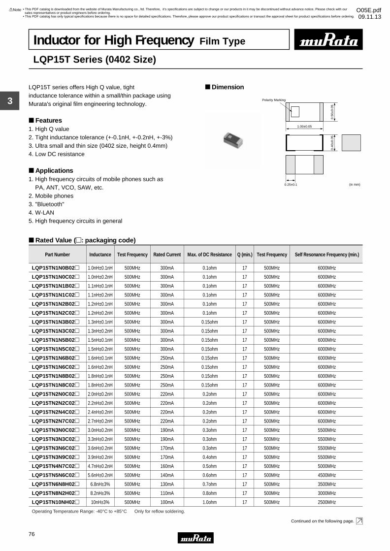
3
!Note • Please read rating and !CAUTION (for storage, operating, rating, soldering, mounting and handling) in this catalog to prevent smoking and/or burning, etc.• This catalog has only typical specifications because there is no space for detailed specifications. Therefore, please approve our product specifications or transact the approval sheet for product specifications before ordering.
76
• This PDF catalog is downloaded from the website of Murata Manufacturing co., ltd. Therefore, it’s specifications are subject to change or our products in it may be discontinued without advance notice. Please check with our sales representatives or product engineers before ordering.
• This PDF catalog has only typical specifications because there is no space for detailed specifications. Therefore, please approve our product specifications or transact the approval sheet for product specifications before ordering.
!Note O05E.pdf09.11.13
Inductor for High Frequency Film Type
LQP15T Series (0402 Size)
LQP15T series offers High Q value, tight inductance tolerance within a small/thin package using Murata's original film engineering technology.
Features1. High Q value2. Tight inductance tolerance (+-0.1nH, +-0.2nH, +-3%)3. Ultra small and thin size (0402 size, height 0.4mm)4. Low DC resistance
Applications1. High frequency circuits of mobile phones such as PA, ANT, VCO, SAW, etc.2. Mobile phones3. "Bluetooth"4. W-LAN5. High frequency circuits in general
Dimension
Rated Value (p: packaging code)
Continued on the following page.
1.00±0.05
0.50
±0.0
50.
40±0
.05
0.25±0.1 (in mm)
Polarity Marking
Part Number Inductance Test Frequency Rated Current Max. of DC Resistance Q (min.) Test Frequency Self Resonance Frequency (min.)
LQP15TN1N0B02p 1.0nH±0.1nH 500MHz 300mA 0.1ohm 17 500MHz 6000MHz
LQP15TN1N0C02p 1.0nH±0.2nH 500MHz 300mA 0.1ohm 17 500MHz 6000MHz
LQP15TN1N1B02p 1.1nH±0.1nH 500MHz 300mA 0.1ohm 17 500MHz 6000MHz
LQP15TN1N1C02p 1.1nH±0.2nH 500MHz 300mA 0.1ohm 17 500MHz 6000MHz
LQP15TN1N2B02p 1.2nH±0.1nH 500MHz 300mA 0.1ohm 17 500MHz 6000MHz
LQP15TN1N2C02p 1.2nH±0.2nH 500MHz 300mA 0.1ohm 17 500MHz 6000MHz
LQP15TN1N3B02p 1.3nH±0.1nH 500MHz 300mA 0.15ohm 17 500MHz 6000MHz
LQP15TN1N3C02p 1.3nH±0.2nH 500MHz 300mA 0.15ohm 17 500MHz 6000MHz
LQP15TN1N5B02p 1.5nH±0.1nH 500MHz 300mA 0.15ohm 17 500MHz 6000MHz
LQP15TN1N5C02p 1.5nH±0.2nH 500MHz 300mA 0.15ohm 17 500MHz 6000MHz
LQP15TN1N6B02p 1.6nH±0.1nH 500MHz 250mA 0.15ohm 17 500MHz 6000MHz
LQP15TN1N6C02p 1.6nH±0.2nH 500MHz 250mA 0.15ohm 17 500MHz 6000MHz
LQP15TN1N8B02p 1.8nH±0.1nH 500MHz 250mA 0.15ohm 17 500MHz 6000MHz
LQP15TN1N8C02p 1.8nH±0.2nH 500MHz 250mA 0.15ohm 17 500MHz 6000MHz
LQP15TN2N0C02p 2.0nH±0.2nH 500MHz 220mA 0.2ohm 17 500MHz 6000MHz
LQP15TN2N2C02p 2.2nH±0.2nH 500MHz 220mA 0.2ohm 17 500MHz 6000MHz
LQP15TN2N4C02p 2.4nH±0.2nH 500MHz 220mA 0.2ohm 17 500MHz 6000MHz
LQP15TN2N7C02p 2.7nH±0.2nH 500MHz 220mA 0.2ohm 17 500MHz 6000MHz
LQP15TN3N0C02p 3.0nH±0.2nH 500MHz 190mA 0.3ohm 17 500MHz 5500MHz
LQP15TN3N3C02p 3.3nH±0.2nH 500MHz 190mA 0.3ohm 17 500MHz 5500MHz
LQP15TN3N6C02p 3.6nH±0.2nH 500MHz 170mA 0.3ohm 17 500MHz 5500MHz
LQP15TN3N9C02p 3.9nH±0.2nH 500MHz 170mA 0.4ohm 17 500MHz 5500MHz
LQP15TN4N7C02p 4.7nH±0.2nH 500MHz 160mA 0.5ohm 17 500MHz 5000MHz
Operating Temperature Range: -40°C to +85°C Only for reflow soldering.
LQP15TN5N6C02p 5.6nH±0.2nH 500MHz 140mA 0.6ohm 17 500MHz 4500MHz
LQP15TN6N8H02p 6.8nH±3% 500MHz 130mA 0.7ohm 17 500MHz 3500MHz
LQP15TN8N2H02p 8.2nH±3% 500MHz 110mA 0.8ohm 17 500MHz 3000MHz
LQP15TN10NH02p 10nH±3% 500MHz 100mA 1.0ohm 17 500MHz 2500MHz
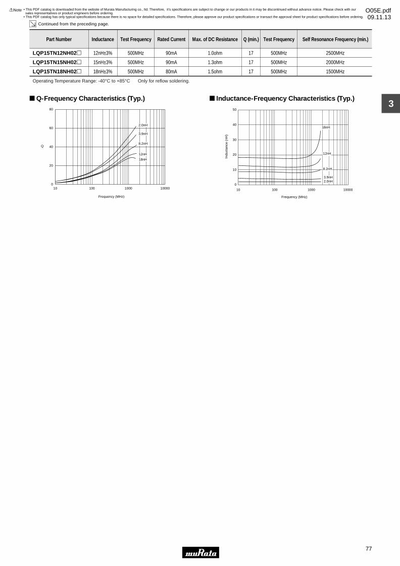
3
!Note • Please read rating and !CAUTION (for storage, operating, rating, soldering, mounting and handling) in this catalog to prevent smoking and/or burning, etc.• This catalog has only typical specifications because there is no space for detailed specifications. Therefore, please approve our product specifications or transact the approval sheet for product specifications before ordering.
77
• This PDF catalog is downloaded from the website of Murata Manufacturing co., ltd. Therefore, it’s specifications are subject to change or our products in it may be discontinued without advance notice. Please check with our sales representatives or product engineers before ordering.
• This PDF catalog has only typical specifications because there is no space for detailed specifications. Therefore, please approve our product specifications or transact the approval sheet for product specifications before ordering.
!Note O05E.pdf09.11.13
Continued from the preceding page.
Part Number Inductance Test Frequency Rated Current Max. of DC Resistance Q (min.) Test Frequency Self Resonance Frequency (min.)
LQP15TN12NH02p 12nH±3% 500MHz 90mA 1.0ohm 17 500MHz 2500MHz
LQP15TN15NH02p 15nH±3% 500MHz 90mA 1.3ohm 17 500MHz 2000MHz
LQP15TN18NH02p 18nH±3% 500MHz 80mA 1.5ohm 17 500MHz 1500MHz
Operating Temperature Range: -40°C to +85°C Only for reflow soldering.
Q
Frequency (MHz)
0
20
40
60
80
10 100 1000 10000
2.0nH
3.9nH
8.2nH
12nH
18nH
Q-Frequency Characteristics (Typ.)
Indu
ctan
ce (
nH)
Frequency (MHz)
0
10
20
30
40
50
10 100 1000 10000
2.0nH3.9nH
8.2nH
12nH
18nH
Inductance-Frequency Characteristics (Typ.)
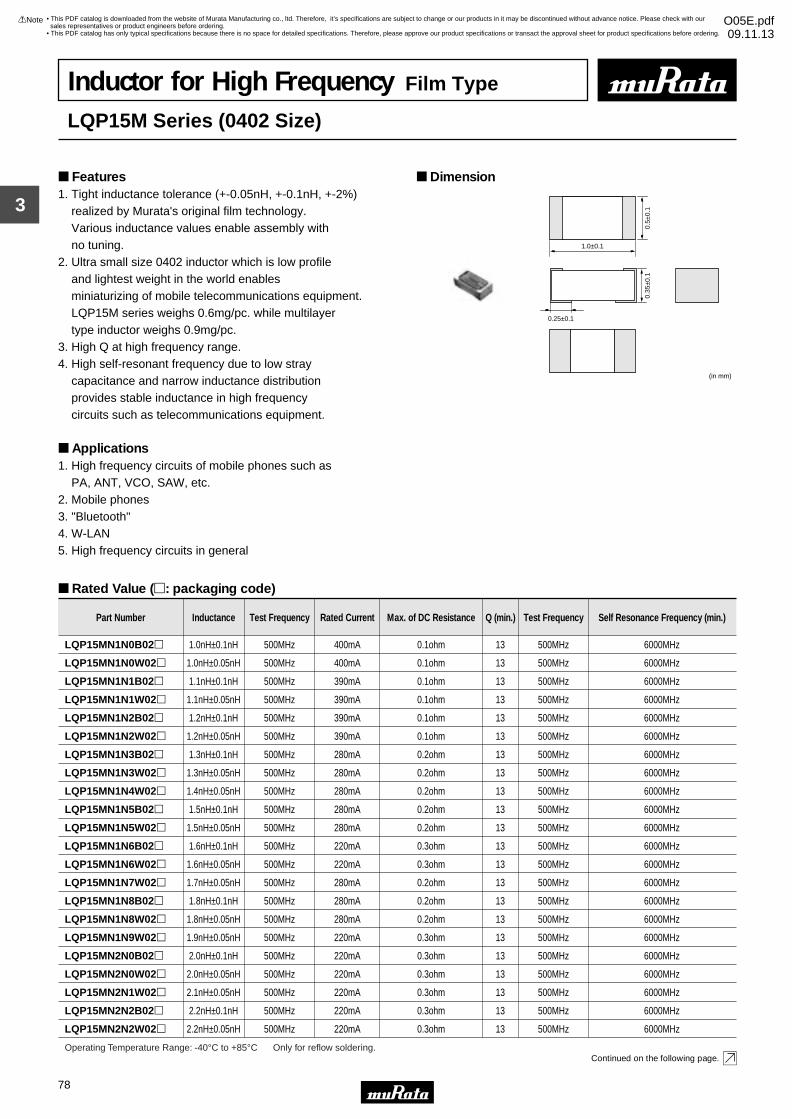
3
!Note • Please read rating and !CAUTION (for storage, operating, rating, soldering, mounting and handling) in this catalog to prevent smoking and/or burning, etc.• This catalog has only typical specifications because there is no space for detailed specifications. Therefore, please approve our product specifications or transact the approval sheet for product specifications before ordering.
78
• This PDF catalog is downloaded from the website of Murata Manufacturing co., ltd. Therefore, it’s specifications are subject to change or our products in it may be discontinued without advance notice. Please check with our sales representatives or product engineers before ordering.
• This PDF catalog has only typical specifications because there is no space for detailed specifications. Therefore, please approve our product specifications or transact the approval sheet for product specifications before ordering.
!Note O05E.pdf09.11.13
Inductor for High Frequency Film Type
LQP15M Series (0402 Size)
1. Tight inductance tolerance (+-0.05nH, +-0.1nH, +-2%) realized by Murata's original film technology. Various inductance values enable assembly with no tuning.2. Ultra small size 0402 inductor which is low profile and lightest weight in the world enables miniaturizing of mobile telecommunications equipment. LQP15M series weighs 0.6mg/pc. while multilayer type inductor weighs 0.9mg/pc.3. High Q at high frequency range.4. High self-resonant frequency due to low stray capacitance and narrow inductance distribution provides stable inductance in high frequency circuits such as telecommunications equipment.
Applications1. High frequency circuits of mobile phones such as PA, ANT, VCO, SAW, etc.2. Mobile phones3. "Bluetooth"4. W-LAN5. High frequency circuits in general
Dimension Features
Rated Value (p: packaging code)
Continued on the following page.
1.0±0.1
0.5±
0.1
0.25±0.1
0.35
±0.1
(in mm)
Part Number Inductance Test Frequency Rated Current Max. of DC Resistance Q (min.) Test Frequency Self Resonance Frequency (min.)
LQP15MN1N0B02p 1.0nH±0.1nH 500MHz 400mA 0.1ohm 13 500MHz 6000MHz
LQP15MN1N0W02p 1.0nH±0.05nH 500MHz 400mA 0.1ohm 13 500MHz 6000MHz
LQP15MN1N1B02p 1.1nH±0.1nH 500MHz 390mA 0.1ohm 13 500MHz 6000MHz
LQP15MN1N1W02p 1.1nH±0.05nH 500MHz 390mA 0.1ohm 13 500MHz 6000MHz
LQP15MN1N2B02p 1.2nH±0.1nH 500MHz 390mA 0.1ohm 13 500MHz 6000MHz
LQP15MN1N2W02p 1.2nH±0.05nH 500MHz 390mA 0.1ohm 13 500MHz 6000MHz
LQP15MN1N3B02p 1.3nH±0.1nH 500MHz 280mA 0.2ohm 13 500MHz 6000MHz
LQP15MN1N3W02p 1.3nH±0.05nH 500MHz 280mA 0.2ohm 13 500MHz 6000MHz
LQP15MN1N4W02p 1.4nH±0.05nH 500MHz 280mA 0.2ohm 13 500MHz 6000MHz
LQP15MN1N5B02p 1.5nH±0.1nH 500MHz 280mA 0.2ohm 13 500MHz 6000MHz
LQP15MN1N5W02p 1.5nH±0.05nH 500MHz 280mA 0.2ohm 13 500MHz 6000MHz
LQP15MN1N6B02p 1.6nH±0.1nH 500MHz 220mA 0.3ohm 13 500MHz 6000MHz
LQP15MN1N6W02p 1.6nH±0.05nH 500MHz 220mA 0.3ohm 13 500MHz 6000MHz
LQP15MN1N7W02p 1.7nH±0.05nH 500MHz 280mA 0.2ohm 13 500MHz 6000MHz
LQP15MN1N8B02p 1.8nH±0.1nH 500MHz 280mA 0.2ohm 13 500MHz 6000MHz
LQP15MN1N8W02p 1.8nH±0.05nH 500MHz 280mA 0.2ohm 13 500MHz 6000MHz
LQP15MN1N9W02p 1.9nH±0.05nH 500MHz 220mA 0.3ohm 13 500MHz 6000MHz
LQP15MN2N0B02p 2.0nH±0.1nH 500MHz 220mA 0.3ohm 13 500MHz 6000MHz
LQP15MN2N0W02p 2.0nH±0.05nH 500MHz 220mA 0.3ohm 13 500MHz 6000MHz
LQP15MN2N1W02p 2.1nH±0.05nH 500MHz 220mA 0.3ohm 13 500MHz 6000MHz
LQP15MN2N2B02p 2.2nH±0.1nH 500MHz 220mA 0.3ohm 13 500MHz 6000MHz
Operating Temperature Range: -40°C to +85°C Only for reflow soldering.
LQP15MN2N2W02p 2.2nH±0.05nH 500MHz 220mA 0.3ohm 13 500MHz 6000MHz
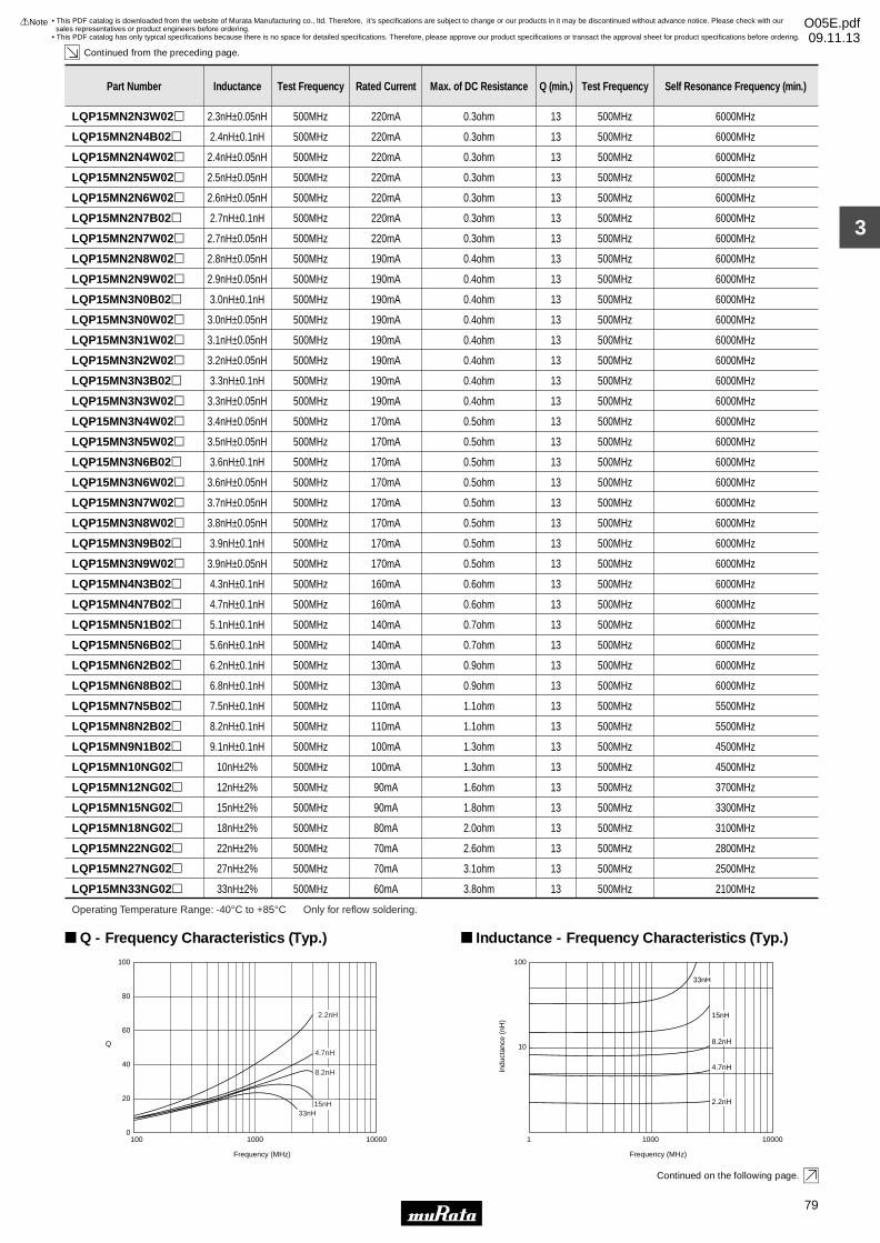
3
!Note • Please read rating and !CAUTION (for storage, operating, rating, soldering, mounting and handling) in this catalog to prevent smoking and/or burning, etc.• This catalog has only typical specifications because there is no space for detailed specifications. Therefore, please approve our product specifications or transact the approval sheet for product specifications before ordering.
79
• This PDF catalog is downloaded from the website of Murata Manufacturing co., ltd. Therefore, it’s specifications are subject to change or our products in it may be discontinued without advance notice. Please check with our sales representatives or product engineers before ordering.
• This PDF catalog has only typical specifications because there is no space for detailed specifications. Therefore, please approve our product specifications or transact the approval sheet for product specifications before ordering.
!Note O05E.pdf09.11.13
Continued from the preceding page.
Continued on the following page.
LQP15MN2N3W02p 2.3nH±0.05nH 500MHz 220mA 0.3ohm 13 500MHz 6000MHz
Part Number Inductance Test Frequency Rated Current Max. of DC Resistance Q (min.) Test Frequency Self Resonance Frequency (min.)
LQP15MN2N4B02p 2.4nH±0.1nH 500MHz 220mA 0.3ohm 13 500MHz 6000MHz
LQP15MN2N4W02p 2.4nH±0.05nH 500MHz 220mA 0.3ohm 13 500MHz 6000MHz
LQP15MN2N5W02p 2.5nH±0.05nH 500MHz 220mA 0.3ohm 13 500MHz 6000MHz
LQP15MN2N6W02p 2.6nH±0.05nH 500MHz 220mA 0.3ohm 13 500MHz 6000MHz
LQP15MN2N7B02p 2.7nH±0.1nH 500MHz 220mA 0.3ohm 13 500MHz 6000MHz
LQP15MN2N7W02p 2.7nH±0.05nH 500MHz 220mA 0.3ohm 13 500MHz 6000MHz
LQP15MN2N8W02p 2.8nH±0.05nH 500MHz 190mA 0.4ohm 13 500MHz 6000MHz
LQP15MN2N9W02p 2.9nH±0.05nH 500MHz 190mA 0.4ohm 13 500MHz 6000MHz
LQP15MN3N0B02p 3.0nH±0.1nH 500MHz 190mA 0.4ohm 13 500MHz 6000MHz
LQP15MN3N0W02p 3.0nH±0.05nH 500MHz 190mA 0.4ohm 13 500MHz 6000MHz
LQP15MN3N1W02p 3.1nH±0.05nH 500MHz 190mA 0.4ohm 13 500MHz 6000MHz
LQP15MN3N2W02p 3.2nH±0.05nH 500MHz 190mA 0.4ohm 13 500MHz 6000MHz
LQP15MN3N3B02p 3.3nH±0.1nH 500MHz 190mA 0.4ohm 13 500MHz 6000MHz
LQP15MN3N3W02p 3.3nH±0.05nH 500MHz 190mA 0.4ohm 13 500MHz 6000MHz
LQP15MN3N4W02p 3.4nH±0.05nH 500MHz 170mA 0.5ohm 13 500MHz 6000MHz
LQP15MN3N5W02p 3.5nH±0.05nH 500MHz 170mA 0.5ohm 13 500MHz 6000MHz
LQP15MN3N6B02p 3.6nH±0.1nH 500MHz 170mA 0.5ohm 13 500MHz 6000MHz
LQP15MN3N6W02p 3.6nH±0.05nH 500MHz 170mA 0.5ohm 13 500MHz 6000MHz
LQP15MN3N7W02p 3.7nH±0.05nH 500MHz 170mA 0.5ohm 13 500MHz 6000MHz
LQP15MN3N8W02p 3.8nH±0.05nH 500MHz 170mA 0.5ohm 13 500MHz 6000MHz
LQP15MN3N9B02p 3.9nH±0.1nH 500MHz 170mA 0.5ohm 13 500MHz 6000MHz
LQP15MN3N9W02p 3.9nH±0.05nH 500MHz 170mA 0.5ohm 13 500MHz 6000MHz
LQP15MN4N3B02p 4.3nH±0.1nH 500MHz 160mA 0.6ohm 13 500MHz 6000MHz
LQP15MN4N7B02p 4.7nH±0.1nH 500MHz 160mA 0.6ohm 13 500MHz 6000MHz
LQP15MN5N1B02p 5.1nH±0.1nH 500MHz 140mA 0.7ohm 13 500MHz 6000MHz
LQP15MN5N6B02p 5.6nH±0.1nH 500MHz 140mA 0.7ohm 13 500MHz 6000MHz
LQP15MN6N2B02p 6.2nH±0.1nH 500MHz 130mA 0.9ohm 13 500MHz 6000MHz
LQP15MN6N8B02p 6.8nH±0.1nH 500MHz 130mA 0.9ohm 13 500MHz 6000MHz
LQP15MN7N5B02p 7.5nH±0.1nH 500MHz 110mA 1.1ohm 13 500MHz 5500MHz
LQP15MN8N2B02p 8.2nH±0.1nH 500MHz 110mA 1.1ohm 13 500MHz 5500MHz
LQP15MN9N1B02p 9.1nH±0.1nH 500MHz 100mA 1.3ohm 13 500MHz 4500MHz
LQP15MN10NG02p 10nH±2% 500MHz 100mA 1.3ohm 13 500MHz 4500MHz
LQP15MN12NG02p 12nH±2% 500MHz 90mA 1.6ohm 13 500MHz 3700MHz
LQP15MN15NG02p 15nH±2% 500MHz 90mA 1.8ohm 13 500MHz 3300MHz
LQP15MN18NG02p 18nH±2% 500MHz 80mA 2.0ohm 13 500MHz 3100MHz
LQP15MN22NG02p 22nH±2% 500MHz 70mA 2.6ohm 13 500MHz 2800MHz
LQP15MN27NG02p 27nH±2% 500MHz 70mA 3.1ohm 13 500MHz 2500MHz
LQP15MN33NG02p 33nH±2% 500MHz 60mA 3.8ohm 13 500MHz 2100MHz
Operating Temperature Range: -40°C to +85°C Only for reflow soldering.
100
80
60
40
20
0100 1000 10000
Frequency (MHz)
Q
33nH15nH
4.7nH
8.2nH
2.2nH
Q - Frequency Characteristics (Typ.)
33nH
15nH
4.7nH
8.2nH
2.2nH
100
10
1 1000 10000
Frequency (MHz)
Indu
ctan
ce (
nH)
Inductance - Frequency Characteristics (Typ.)
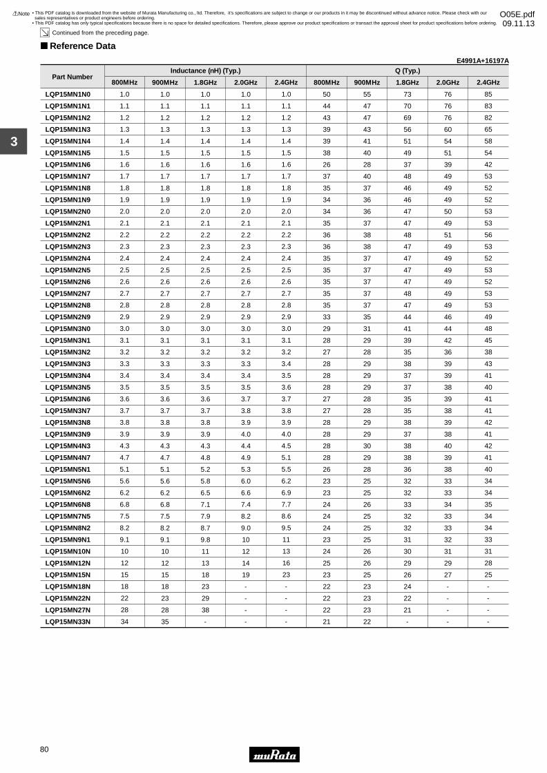
3
!Note • Please read rating and !CAUTION (for storage, operating, rating, soldering, mounting and handling) in this catalog to prevent smoking and/or burning, etc.• This catalog has only typical specifications because there is no space for detailed specifications. Therefore, please approve our product specifications or transact the approval sheet for product specifications before ordering.
80
• This PDF catalog is downloaded from the website of Murata Manufacturing co., ltd. Therefore, it’s specifications are subject to change or our products in it may be discontinued without advance notice. Please check with our sales representatives or product engineers before ordering.
• This PDF catalog has only typical specifications because there is no space for detailed specifications. Therefore, please approve our product specifications or transact the approval sheet for product specifications before ordering.
!Note O05E.pdf09.11.13
Continued from the preceding page.
Reference Data
Part Number
LQP15MN1N0
LQP15MN1N1
LQP15MN1N2
LQP15MN1N3
LQP15MN1N4
LQP15MN1N5
LQP15MN1N6
LQP15MN1N7
LQP15MN1N8
LQP15MN1N9
LQP15MN2N0
LQP15MN2N1
LQP15MN2N2
LQP15MN2N3
LQP15MN2N4
LQP15MN2N5
LQP15MN2N6
LQP15MN2N7
LQP15MN2N8
LQP15MN2N9
LQP15MN3N0
LQP15MN3N1
LQP15MN3N2
LQP15MN3N3
LQP15MN3N4
LQP15MN3N5
LQP15MN3N6
LQP15MN3N7
LQP15MN3N8
LQP15MN3N9
LQP15MN4N3
LQP15MN4N7
LQP15MN5N1
LQP15MN5N6
LQP15MN6N2
LQP15MN6N8
LQP15MN7N5
LQP15MN8N2
LQP15MN9N1
LQP15MN10N
LQP15MN12N
LQP15MN15N
LQP15MN18N
LQP15MN22N
LQP15MN27N
LQP15MN33N
1.0
1.1
1.2
1.3
1.4
1.5
1.6
1.7
1.8
1.9
2.0
2.1
2.2
2.3
2.4
2.5
2.6
2.7
2.8
2.9
3.0
3.1
3.2
3.3
3.4
3.5
3.6
3.7
3.8
3.9
4.3
4.7
5.1
5.6
6.2
6.8
7.5
8.2
9.1
10
12
15
18
22
28
34
800MHz
1.0
1.1
1.2
1.3
1.4
1.5
1.6
1.7
1.8
1.9
2.0
2.1
2.2
2.3
2.4
2.5
2.6
2.7
2.8
2.9
3.0
3.1
3.2
3.3
3.4
3.5
3.6
3.7
3.8
3.9
4.3
4.7
5.1
5.6
6.2
6.8
7.5
8.2
9.1
10
12
15
18
23
28
35
900MHz
1.0
1.1
1.2
1.3
1.4
1.5
1.6
1.7
1.8
1.9
2.0
2.1
2.2
2.3
2.4
2.5
2.6
2.7
2.8
2.9
3.0
3.1
3.2
3.3
3.4
3.5
3.6
3.7
3.8
3.9
4.3
4.8
5.2
5.8
6.5
7.1
7.9
8.7
9.8
11
13
18
23
29
38
-
1.8GHz
1.0
1.1
1.2
1.3
1.4
1.5
1.6
1.7
1.8
1.9
2.0
2.1
2.2
2.3
2.4
2.5
2.6
2.7
2.8
2.9
3.0
3.1
3.2
3.3
3.4
3.5
3.7
3.8
3.9
4.0
4.4
4.9
5.3
6.0
6.6
7.4
8.2
9.0
10
12
14
19
-
-
-
-
2.0GHz
1.0
1.1
1.2
1.3
1.4
1.5
1.6
1.7
1.8
1.9
2.0
2.1
2.2
2.3
2.4
2.5
2.6
2.7
2.8
2.9
3.0
3.1
3.2
3.4
3.5
3.6
3.7
3.8
3.9
4.0
4.5
5.1
5.5
6.2
6.9
7.7
8.6
9.5
11
13
16
23
-
-
-
-
2.4GHz
Inductance (nH) (Typ.)
50
44
43
39
39
38
26
37
35
34
34
35
36
36
35
35
35
35
35
33
29
28
27
28
28
28
27
27
28
28
28
28
26
23
23
24
24
24
23
24
25
23
22
22
22
21
800MHz
55
47
47
43
41
40
28
40
37
36
36
37
38
38
37
37
37
37
37
35
31
29
28
29
29
29
28
28
29
29
30
29
28
25
25
26
25
25
25
26
26
25
23
23
23
22
900MHz
73
70
69
56
51
49
37
48
46
46
47
47
48
47
47
47
47
48
47
44
41
39
35
38
37
37
35
35
38
37
38
38
36
32
32
33
32
32
31
30
29
26
24
22
21
-
1.8GHz
76
76
76
60
54
51
39
49
49
49
50
49
51
49
49
49
49
49
49
46
44
42
36
39
39
38
39
38
39
38
40
39
38
33
33
34
33
33
32
31
29
27
-
-
-
-
2.0GHz
85
83
82
65
58
54
42
53
52
52
53
53
56
53
52
53
52
53
53
49
48
45
38
43
41
40
41
41
42
41
42
41
40
34
34
35
34
34
33
31
28
25
-
-
-
-
2.4GHz
Q (Typ.)E4991A+16197A
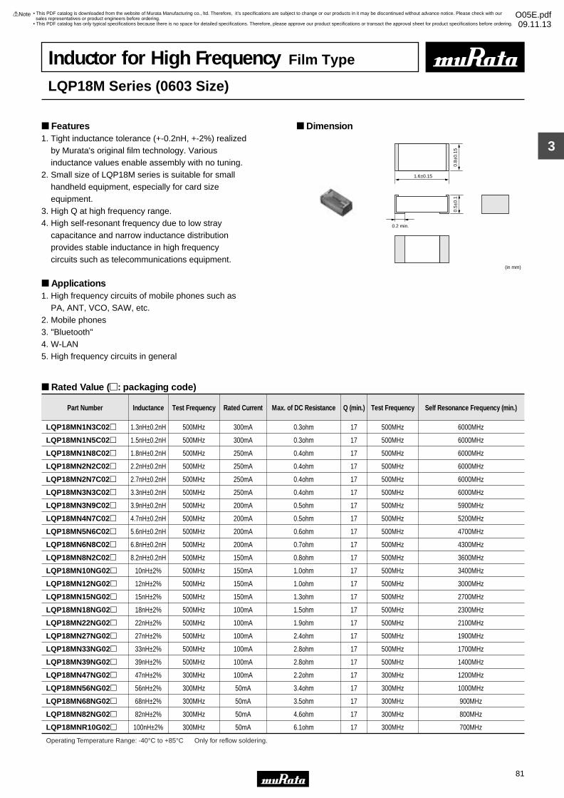
3
!Note • Please read rating and !CAUTION (for storage, operating, rating, soldering, mounting and handling) in this catalog to prevent smoking and/or burning, etc.• This catalog has only typical specifications because there is no space for detailed specifications. Therefore, please approve our product specifications or transact the approval sheet for product specifications before ordering.
81
• This PDF catalog is downloaded from the website of Murata Manufacturing co., ltd. Therefore, it’s specifications are subject to change or our products in it may be discontinued without advance notice. Please check with our sales representatives or product engineers before ordering.
• This PDF catalog has only typical specifications because there is no space for detailed specifications. Therefore, please approve our product specifications or transact the approval sheet for product specifications before ordering.
!Note O05E.pdf09.11.13
Inductor for High Frequency Film Type
LQP18M Series (0603 Size)
1. Tight inductance tolerance (+-0.2nH, +-2%) realized by Murata's original film technology. Various inductance values enable assembly with no tuning.2. Small size of LQP18M series is suitable for small handheld equipment, especially for card size equipment.3. High Q at high frequency range.4. High self-resonant frequency due to low stray capacitance and narrow inductance distribution provides stable inductance in high frequency circuits such as telecommunications equipment.
Applications1. High frequency circuits of mobile phones such as PA, ANT, VCO, SAW, etc.2. Mobile phones3. "Bluetooth"4. W-LAN5. High frequency circuits in general
Dimension Features
Rated Value (p: packaging code)
1.6±0.15
0.2 min.
0.8±
0.15
0.5±
0.1
(in mm)
Part Number Inductance Test Frequency Rated Current Max. of DC Resistance Q (min.) Test Frequency Self Resonance Frequency (min.)
LQP18MN1N3C02p 1.3nH±0.2nH 500MHz 300mA 0.3ohm 17 500MHz 6000MHz
LQP18MN1N5C02p 1.5nH±0.2nH 500MHz 300mA 0.3ohm 17 500MHz 6000MHz
LQP18MN1N8C02p 1.8nH±0.2nH 500MHz 250mA 0.4ohm 17 500MHz 6000MHz
LQP18MN2N2C02p 2.2nH±0.2nH 500MHz 250mA 0.4ohm 17 500MHz 6000MHz
LQP18MN2N7C02p 2.7nH±0.2nH 500MHz 250mA 0.4ohm 17 500MHz 6000MHz
LQP18MN3N3C02p 3.3nH±0.2nH 500MHz 250mA 0.4ohm 17 500MHz 6000MHz
LQP18MN3N9C02p 3.9nH±0.2nH 500MHz 200mA 0.5ohm 17 500MHz 5900MHz
LQP18MN4N7C02p 4.7nH±0.2nH 500MHz 200mA 0.5ohm 17 500MHz 5200MHz
LQP18MN5N6C02p 5.6nH±0.2nH 500MHz 200mA 0.6ohm 17 500MHz 4700MHz
LQP18MN6N8C02p 6.8nH±0.2nH 500MHz 200mA 0.7ohm 17 500MHz 4300MHz
LQP18MN8N2C02p 8.2nH±0.2nH 500MHz 150mA 0.8ohm 17 500MHz 3600MHz
LQP18MN10NG02p 10nH±2% 500MHz 150mA 1.0ohm 17 500MHz 3400MHz
LQP18MN12NG02p 12nH±2% 500MHz 150mA 1.0ohm 17 500MHz 3000MHz
LQP18MN15NG02p 15nH±2% 500MHz 150mA 1.3ohm 17 500MHz 2700MHz
LQP18MN18NG02p 18nH±2% 500MHz 100mA 1.5ohm 17 500MHz 2300MHz
LQP18MN22NG02p 22nH±2% 500MHz 100mA 1.9ohm 17 500MHz 2100MHz
LQP18MN27NG02p 27nH±2% 500MHz 100mA 2.4ohm 17 500MHz 1900MHz
LQP18MN33NG02p 33nH±2% 500MHz 100mA 2.8ohm 17 500MHz 1700MHz
LQP18MN39NG02p 39nH±2% 500MHz 100mA 2.8ohm 17 500MHz 1400MHz
LQP18MN47NG02p 47nH±2% 300MHz 100mA 2.2ohm 17 300MHz 1200MHz
LQP18MN56NG02p 56nH±2% 300MHz 50mA 3.4ohm 17 300MHz 1000MHz
LQP18MN68NG02p 68nH±2% 300MHz 50mA 3.5ohm 17 300MHz 900MHz
LQP18MN82NG02p 82nH±2% 300MHz 50mA 4.6ohm 17 300MHz 800MHz
LQP18MNR10G02p 100nH±2% 300MHz 50mA 6.1ohm 17 300MHz 700MHz
Operating Temperature Range: -40°C to +85°C Only for reflow soldering.
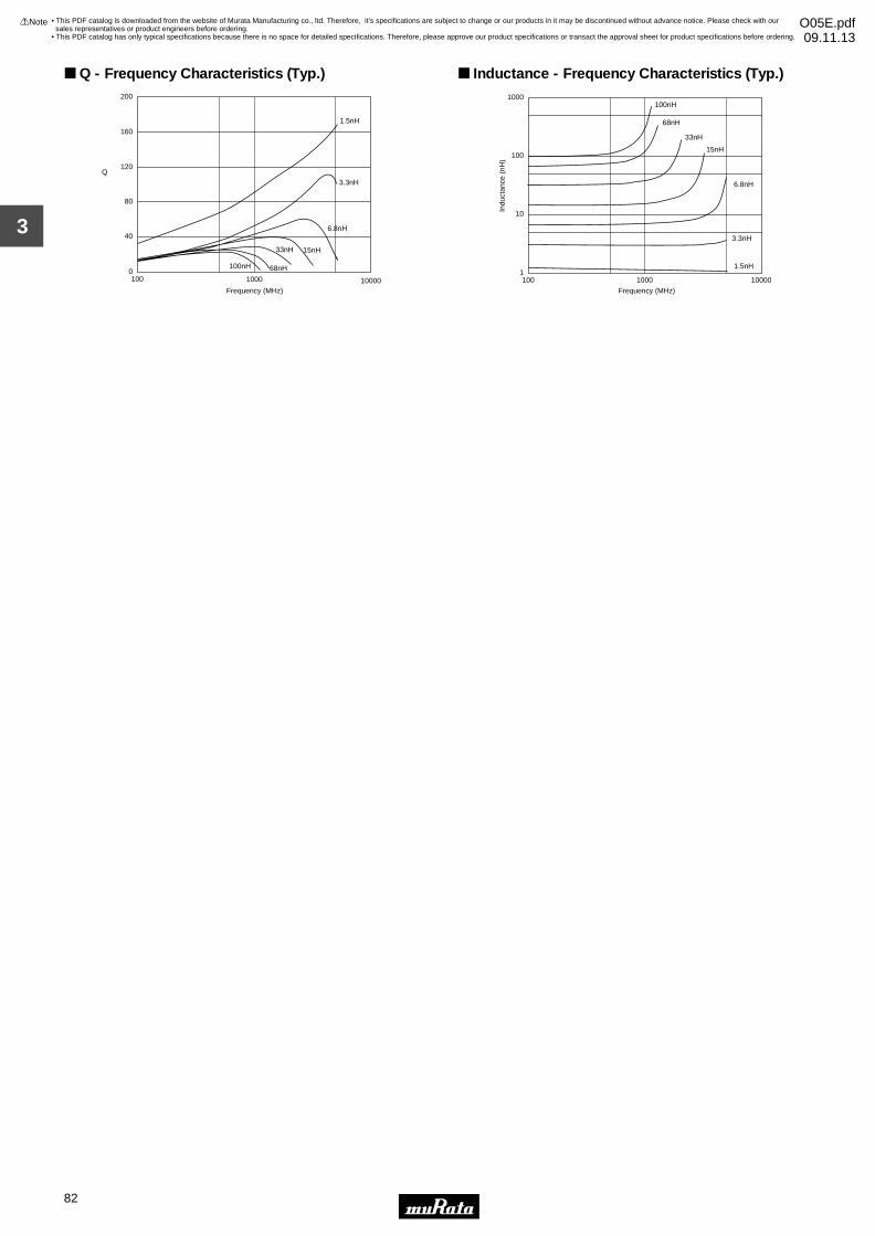
3
!Note • Please read rating and !CAUTION (for storage, operating, rating, soldering, mounting and handling) in this catalog to prevent smoking and/or burning, etc.• This catalog has only typical specifications because there is no space for detailed specifications. Therefore, please approve our product specifications or transact the approval sheet for product specifications before ordering.
82
• This PDF catalog is downloaded from the website of Murata Manufacturing co., ltd. Therefore, it’s specifications are subject to change or our products in it may be discontinued without advance notice. Please check with our sales representatives or product engineers before ordering.
• This PDF catalog has only typical specifications because there is no space for detailed specifications. Therefore, please approve our product specifications or transact the approval sheet for product specifications before ordering.
!Note O05E.pdf09.11.13
100 1000 10000
200
160
120
80
40
0
Q
1.5nH
3.3nH
6.8nH
15nH33nH
68nH100nH
Frequency (MHz)
Q - Frequency Characteristics (Typ.)
100 1000 10000
Frequency (MHz)
1000
100
10
11.5nH
3.3nH
6.8nH
15nH
33nH
68nH
100nH
Indu
ctan
ce (
nH)
Inductance - Frequency Characteristics (Typ.)
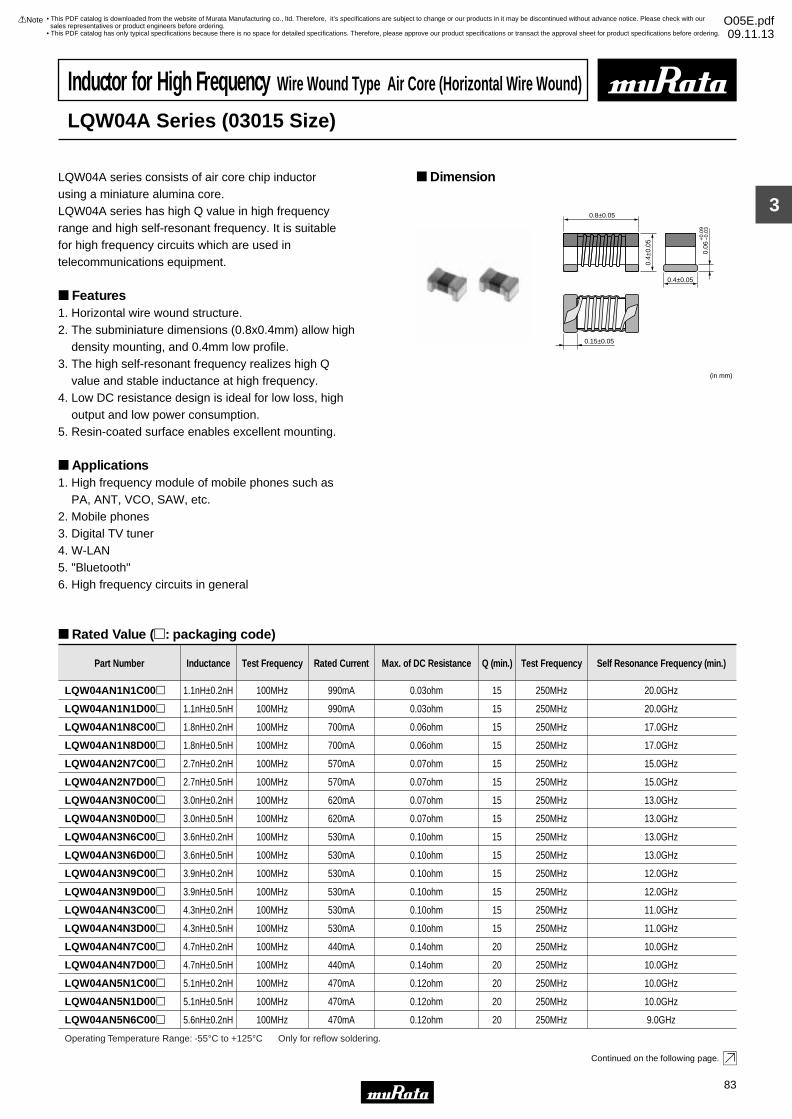
3
!Note • Please read rating and !CAUTION (for storage, operating, rating, soldering, mounting and handling) in this catalog to prevent smoking and/or burning, etc.• This catalog has only typical specifications because there is no space for detailed specifications. Therefore, please approve our product specifications or transact the approval sheet for product specifications before ordering.
83
• This PDF catalog is downloaded from the website of Murata Manufacturing co., ltd. Therefore, it’s specifications are subject to change or our products in it may be discontinued without advance notice. Please check with our sales representatives or product engineers before ordering.
• This PDF catalog has only typical specifications because there is no space for detailed specifications. Therefore, please approve our product specifications or transact the approval sheet for product specifications before ordering.
!Note O05E.pdf09.11.13
Inductor for High Frequency Wire Wound Type Air Core (Horizontal Wire Wound)
LQW04A Series (03015 Size)
LQW04A series consists of air core chip inductorusing a miniature alumina core.LQW04A series has high Q value in high frequency range and high self-resonant frequency. It is suitable for high frequency circuits which are used in telecommunications equipment.
Features1. Horizontal wire wound structure.2. The subminiature dimensions (0.8x0.4mm) allow high density mounting, and 0.4mm low profile.3. The high self-resonant frequency realizes high Q value and stable inductance at high frequency.4. Low DC resistance design is ideal for low loss, high output and low power consumption.5. Resin-coated surface enables excellent mounting.
Applications1. High frequency module of mobile phones such as PA, ANT, VCO, SAW, etc.2. Mobile phones3. Digital TV tuner4. W-LAN5. "Bluetooth"6. High frequency circuits in general
Dimension
Rated Value (p: packaging code)
Continued on the following page.
0.8±0.05
0.4±
0.05
0.15±0.05
(in mm)
0.4±0.05
0.06
+0.
09-
0.03
Part Number Inductance Test Frequency Rated Current Max. of DC Resistance Q (min.) Test Frequency Self Resonance Frequency (min.)
LQW04AN1N1C00p 1.1nH±0.2nH 100MHz 990mA 0.03ohm 15 250MHz 20.0GHz
LQW04AN1N1D00p 1.1nH±0.5nH 100MHz 990mA 0.03ohm 15 250MHz 20.0GHz
LQW04AN1N8C00p 1.8nH±0.2nH 100MHz 700mA 0.06ohm 15 250MHz 17.0GHz
LQW04AN1N8D00p 1.8nH±0.5nH 100MHz 700mA 0.06ohm 15 250MHz 17.0GHz
LQW04AN2N7C00p 2.7nH±0.2nH 100MHz 570mA 0.07ohm 15 250MHz 15.0GHz
LQW04AN2N7D00p 2.7nH±0.5nH 100MHz 570mA 0.07ohm 15 250MHz 15.0GHz
LQW04AN3N0C00p 3.0nH±0.2nH 100MHz 620mA 0.07ohm 15 250MHz 13.0GHz
LQW04AN3N0D00p 3.0nH±0.5nH 100MHz 620mA 0.07ohm 15 250MHz 13.0GHz
LQW04AN3N6C00p 3.6nH±0.2nH 100MHz 530mA 0.10ohm 15 250MHz 13.0GHz
LQW04AN3N6D00p 3.6nH±0.5nH 100MHz 530mA 0.10ohm 15 250MHz 13.0GHz
LQW04AN3N9C00p 3.9nH±0.2nH 100MHz 530mA 0.10ohm 15 250MHz 12.0GHz
LQW04AN3N9D00p 3.9nH±0.5nH 100MHz 530mA 0.10ohm 15 250MHz 12.0GHz
LQW04AN4N3C00p 4.3nH±0.2nH 100MHz 530mA 0.10ohm 15 250MHz 11.0GHz
LQW04AN4N3D00p 4.3nH±0.5nH 100MHz 530mA 0.10ohm 15 250MHz 11.0GHz
LQW04AN4N7C00p 4.7nH±0.2nH 100MHz 440mA 0.14ohm 20 250MHz 10.0GHz
LQW04AN4N7D00p 4.7nH±0.5nH 100MHz 440mA 0.14ohm 20 250MHz 10.0GHz
LQW04AN5N1C00p 5.1nH±0.2nH 100MHz 470mA 0.12ohm 20 250MHz 10.0GHz
LQW04AN5N1D00p 5.1nH±0.5nH 100MHz 470mA 0.12ohm 20 250MHz 10.0GHz
LQW04AN5N6C00p 5.6nH±0.2nH 100MHz 470mA 0.12ohm 20 250MHz 9.0GHz
Operating Temperature Range: -55°C to +125°C Only for reflow soldering.
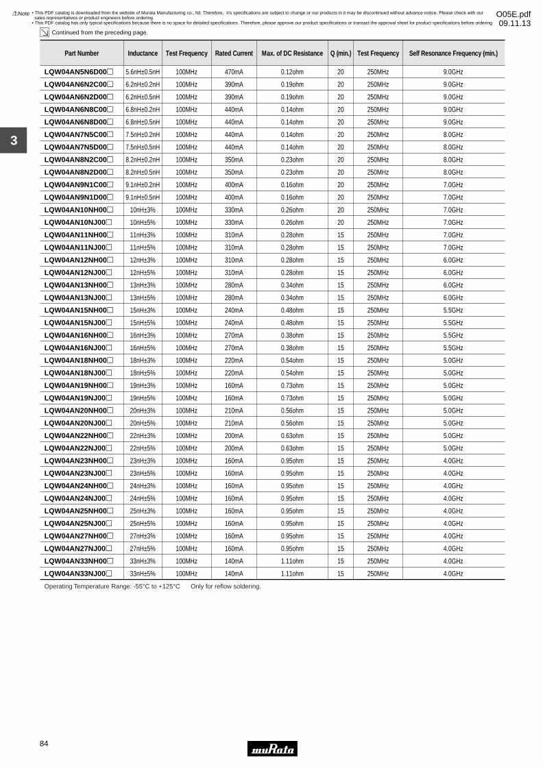
3
!Note • Please read rating and !CAUTION (for storage, operating, rating, soldering, mounting and handling) in this catalog to prevent smoking and/or burning, etc.• This catalog has only typical specifications because there is no space for detailed specifications. Therefore, please approve our product specifications or transact the approval sheet for product specifications before ordering.
84
• This PDF catalog is downloaded from the website of Murata Manufacturing co., ltd. Therefore, it’s specifications are subject to change or our products in it may be discontinued without advance notice. Please check with our sales representatives or product engineers before ordering.
• This PDF catalog has only typical specifications because there is no space for detailed specifications. Therefore, please approve our product specifications or transact the approval sheet for product specifications before ordering.
!Note O05E.pdf09.11.13
Continued from the preceding page.
LQW04AN5N6D00p 5.6nH±0.5nH 100MHz 470mA 0.12ohm 20 250MHz 9.0GHz
LQW04AN6N2C00p 6.2nH±0.2nH 100MHz 390mA 0.19ohm 20 250MHz 9.0GHz
LQW04AN6N2D00p 6.2nH±0.5nH 100MHz 390mA 0.19ohm 20 250MHz 9.0GHz
LQW04AN6N8C00p 6.8nH±0.2nH 100MHz 440mA 0.14ohm 20 250MHz 9.0GHz
Part Number Inductance Test Frequency Rated Current Max. of DC Resistance Q (min.) Test Frequency Self Resonance Frequency (min.)
LQW04AN6N8D00p 6.8nH±0.5nH 100MHz 440mA 0.14ohm 20 250MHz 9.0GHz
LQW04AN7N5C00p 7.5nH±0.2nH 100MHz 440mA 0.14ohm 20 250MHz 8.0GHz
LQW04AN7N5D00p 7.5nH±0.5nH 100MHz 440mA 0.14ohm 20 250MHz 8.0GHz
LQW04AN8N2C00p 8.2nH±0.2nH 100MHz 350mA 0.23ohm 20 250MHz 8.0GHz
LQW04AN8N2D00p 8.2nH±0.5nH 100MHz 350mA 0.23ohm 20 250MHz 8.0GHz
LQW04AN9N1C00p 9.1nH±0.2nH 100MHz 400mA 0.16ohm 20 250MHz 7.0GHz
LQW04AN9N1D00p 9.1nH±0.5nH 100MHz 400mA 0.16ohm 20 250MHz 7.0GHz
LQW04AN10NH00p 10nH±3% 100MHz 330mA 0.26ohm 20 250MHz 7.0GHz
LQW04AN10NJ00p 10nH±5% 100MHz 330mA 0.26ohm 20 250MHz 7.0GHz
LQW04AN11NH00p 11nH±3% 100MHz 310mA 0.28ohm 15 250MHz 7.0GHz
LQW04AN11NJ00p 11nH±5% 100MHz 310mA 0.28ohm 15 250MHz 7.0GHz
LQW04AN12NH00p 12nH±3% 100MHz 310mA 0.28ohm 15 250MHz 6.0GHz
LQW04AN12NJ00p 12nH±5% 100MHz 310mA 0.28ohm 15 250MHz 6.0GHz
LQW04AN13NH00p 13nH±3% 100MHz 280mA 0.34ohm 15 250MHz 6.0GHz
LQW04AN13NJ00p 13nH±5% 100MHz 280mA 0.34ohm 15 250MHz 6.0GHz
LQW04AN15NH00p 15nH±3% 100MHz 240mA 0.48ohm 15 250MHz 5.5GHz
LQW04AN15NJ00p 15nH±5% 100MHz 240mA 0.48ohm 15 250MHz 5.5GHz
LQW04AN16NH00p 16nH±3% 100MHz 270mA 0.38ohm 15 250MHz 5.5GHz
LQW04AN16NJ00p 16nH±5% 100MHz 270mA 0.38ohm 15 250MHz 5.5GHz
LQW04AN18NH00p 18nH±3% 100MHz 220mA 0.54ohm 15 250MHz 5.0GHz
LQW04AN18NJ00p 18nH±5% 100MHz 220mA 0.54ohm 15 250MHz 5.0GHz
LQW04AN19NH00p 19nH±3% 100MHz 160mA 0.73ohm 15 250MHz 5.0GHz
LQW04AN19NJ00p 19nH±5% 100MHz 160mA 0.73ohm 15 250MHz 5.0GHz
LQW04AN20NH00p 20nH±3% 100MHz 210mA 0.56ohm 15 250MHz 5.0GHz
LQW04AN20NJ00p 20nH±5% 100MHz 210mA 0.56ohm 15 250MHz 5.0GHz
LQW04AN22NH00p 22nH±3% 100MHz 200mA 0.63ohm 15 250MHz 5.0GHz
LQW04AN22NJ00p 22nH±5% 100MHz 200mA 0.63ohm 15 250MHz 5.0GHz
LQW04AN23NH00p 23nH±3% 100MHz 160mA 0.95ohm 15 250MHz 4.0GHz
LQW04AN23NJ00p 23nH±5% 100MHz 160mA 0.95ohm 15 250MHz 4.0GHz
LQW04AN24NH00p 24nH±3% 100MHz 160mA 0.95ohm 15 250MHz 4.0GHz
LQW04AN24NJ00p 24nH±5% 100MHz 160mA 0.95ohm 15 250MHz 4.0GHz
LQW04AN25NH00p 25nH±3% 100MHz 160mA 0.95ohm 15 250MHz 4.0GHz
LQW04AN25NJ00p 25nH±5% 100MHz 160mA 0.95ohm 15 250MHz 4.0GHz
LQW04AN27NH00p 27nH±3% 100MHz 160mA 0.95ohm 15 250MHz 4.0GHz
LQW04AN27NJ00p 27nH±5% 100MHz 160mA 0.95ohm 15 250MHz 4.0GHz
LQW04AN33NH00p 33nH±3% 100MHz 140mA 1.11ohm 15 250MHz 4.0GHz
LQW04AN33NJ00p 33nH±5% 100MHz 140mA 1.11ohm 15 250MHz 4.0GHz
Operating Temperature Range: -55°C to +125°C Only for reflow soldering.
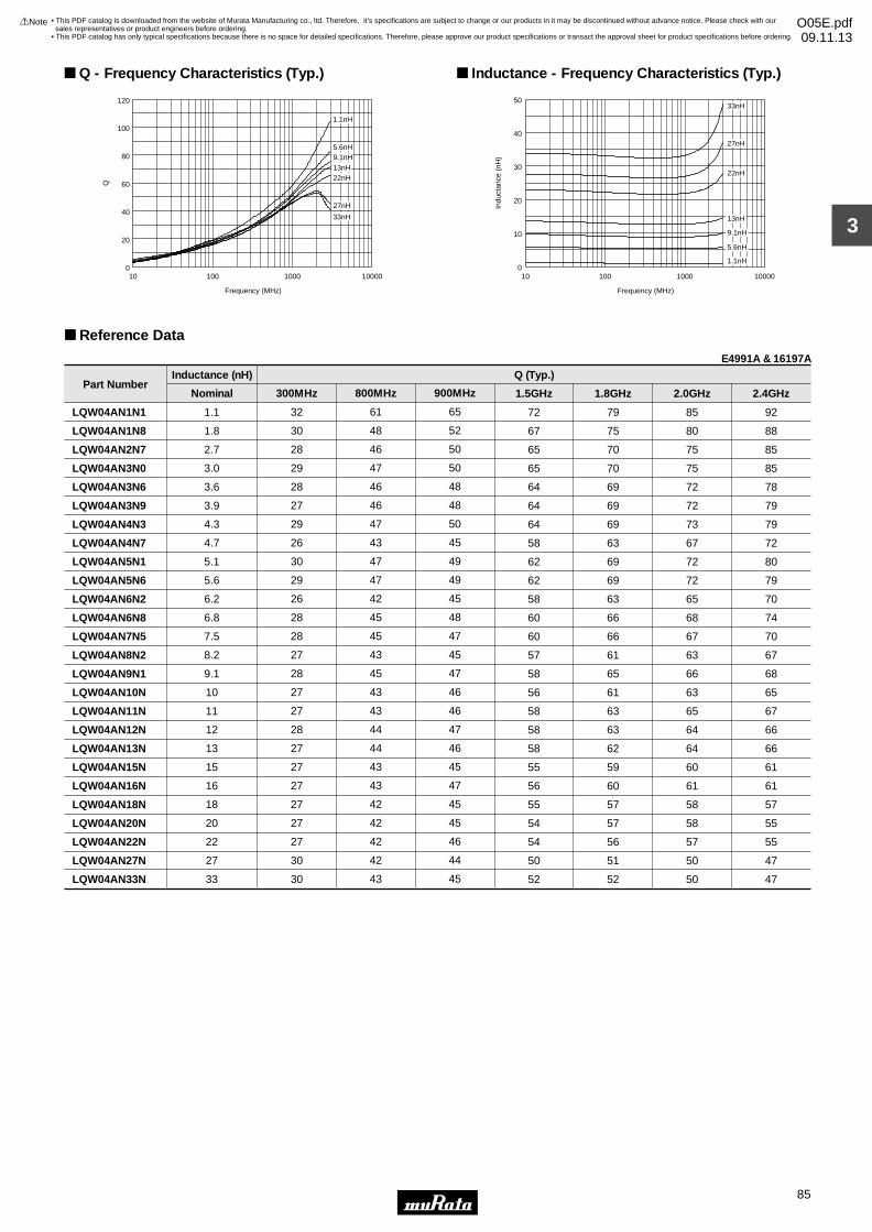
3
!Note • Please read rating and !CAUTION (for storage, operating, rating, soldering, mounting and handling) in this catalog to prevent smoking and/or burning, etc.• This catalog has only typical specifications because there is no space for detailed specifications. Therefore, please approve our product specifications or transact the approval sheet for product specifications before ordering.
85
• This PDF catalog is downloaded from the website of Murata Manufacturing co., ltd. Therefore, it’s specifications are subject to change or our products in it may be discontinued without advance notice. Please check with our sales representatives or product engineers before ordering.
• This PDF catalog has only typical specifications because there is no space for detailed specifications. Therefore, please approve our product specifications or transact the approval sheet for product specifications before ordering.
!Note O05E.pdf09.11.13
Reference Data
Part Number
LQW04AN1N1
LQW04AN1N8
LQW04AN2N7
LQW04AN3N0
LQW04AN3N6
LQW04AN3N9
LQW04AN4N3
LQW04AN4N7
LQW04AN5N1
LQW04AN5N6
LQW04AN6N2
LQW04AN6N8
LQW04AN7N5
LQW04AN8N2
LQW04AN9N1
LQW04AN10N
LQW04AN11N
LQW04AN12N
LQW04AN13N
LQW04AN15N
LQW04AN16N
LQW04AN18N
LQW04AN20N
LQW04AN22N
LQW04AN27N
LQW04AN33N
1.1
1.8
2.7
3.0
3.6
3.9
4.3
4.7
5.1
5.6
6.2
6.8
7.5
8.2
9.1
10
11
12
13
15
16
18
20
22
27
33
Nominal
32
30
28
29
28
27
29
26
30
29
26
28
28
27
28
27
27
28
27
27
27
27
27
27
30
30
300MHz
61
48
46
47
46
46
47
43
47
47
42
45
45
43
45
43
43
44
44
43
43
42
42
42
42
43
800MHz
65
52
50
50
48
48
50
45
49
49
45
48
47
45
47
46
46
47
46
45
47
45
45
46
44
45
900MHz
72
67
65
65
64
64
64
58
62
62
58
60
60
57
58
56
58
58
58
55
56
55
54
54
50
52
1.5GHz
79
75
70
70
69
69
69
63
69
69
63
66
66
61
65
61
63
63
62
59
60
57
57
56
51
52
1.8GHz
85
80
75
75
72
72
73
67
72
72
65
68
67
63
66
63
65
64
64
60
61
58
58
57
50
50
2.0GHz
92
88
85
85
78
79
79
72
80
79
70
74
70
67
68
65
67
66
66
61
61
57
55
55
47
47
2.4GHz
Inductance (nH) Q (Typ.)
E4991A & 16197A
0
20
40
60
80
100
120
10 100 1000 10000
Frequency (MHz)
Q
1.1nH
5.6nH9.1nH
22nH13nH
27nH
33nH
Q - Frequency Characteristics (Typ.)
0
10
20
30
40
50
10 100 1000 10000
Frequency (MHz)
Indu
ctan
ce (
nH)
1.1nH
5.6nH
9.1nH
13nH
22nH
27nH
33nH
Inductance - Frequency Characteristics (Typ.)
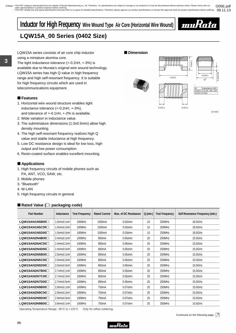
3
!Note • Please read rating and !CAUTION (for storage, operating, rating, soldering, mounting and handling) in this catalog to prevent smoking and/or burning, etc.• This catalog has only typical specifications because there is no space for detailed specifications. Therefore, please approve our product specifications or transact the approval sheet for product specifications before ordering.
86
• This PDF catalog is downloaded from the website of Murata Manufacturing co., ltd. Therefore, it’s specifications are subject to change or our products in it may be discontinued without advance notice. Please check with our sales representatives or product engineers before ordering.
• This PDF catalog has only typical specifications because there is no space for detailed specifications. Therefore, please approve our product specifications or transact the approval sheet for product specifications before ordering.
!Note O05E.pdf09.11.13
Inductor for High Frequency Wire Wound Type Air Core (Horizontal Wire Wound)
LQW15A_00 Series (0402 Size)
LQW15A series consists of air core chip inductorusing a miniature alumina core.The tight inductance tolerance (+-0.2nH, +-3%) is available due to Murata's original wire wound technology.LQW15A series has high Q value in high frequency range and high self-resonant frequency. It is suitable for high frequency circuits which are used in telecommunications equipment.
Features1. Horizontal wire wound structure enables tight inductance tolerance (+-0.2nH, +-3%), and tolerance of +-0.1nH, +-2% is available.2. Wide variation in inductance value. 3. The subminiature dimensions (1.0x0.5mm) allow high density mounting.4. The high self-resonant frequency realizes high Q value and stable inductance at high frequency.5. Low DC resistance design is ideal for low loss, high output and low power consumption.6. Resin-coated surface enables excellent mounting.
Applications1. High frequency circuits of mobile phones such as PA, ANT, VCO, SAW, etc.2. Mobile phones3. "Bluetooth"4. W-LAN5. High frequency circuits in general
Dimension
Rated Value (p: packaging code)
Continued on the following page.
1.0±0.1
0.5±
0.1
0.10
±0.0
5
0.2±0.1 0.2±0.1
W∗
W0.6±0.10.5±0.1
Inductance (nH)1.5-23, 100, 12024-91
(in mm)
∗
0.5±0.1
Part Number Inductance Test Frequency Rated Current Max. of DC Resistance Q (min.) Test Frequency Self Resonance Frequency (min.)
LQW15AN1N5B00p 1.5nH±0.1nH 100MHz 1000mA 0.03ohm 10 250MHz 18.0GHz
LQW15AN1N5C00p 1.5nH±0.2nH 100MHz 1000mA 0.03ohm 10 250MHz 18.0GHz
LQW15AN1N5D00p 1.5nH±0.5nH 100MHz 1000mA 0.03ohm 10 250MHz 18.0GHz
LQW15AN2N4B00p 2.4nH±0.1nH 100MHz 850mA 0.05ohm 20 250MHz 15.0GHz
LQW15AN2N4C00p 2.4nH±0.2nH 100MHz 850mA 0.05ohm 20 250MHz 15.0GHz
LQW15AN2N4D00p 2.4nH±0.5nH 100MHz 850mA 0.05ohm 20 250MHz 15.0GHz
LQW15AN2N5B00p 2.5nH±0.1nH 100MHz 850mA 0.05ohm 20 250MHz 15.0GHz
LQW15AN2N5C00p 2.5nH±0.2nH 100MHz 850mA 0.05ohm 20 250MHz 15.0GHz
LQW15AN2N5D00p 2.5nH±0.5nH 100MHz 850mA 0.05ohm 20 250MHz 15.0GHz
LQW15AN2N7B00p 2.7nH±0.1nH 100MHz 850mA 0.05ohm 20 250MHz 15.0GHz
LQW15AN2N7C00p 2.7nH±0.2nH 100MHz 850mA 0.05ohm 20 250MHz 15.0GHz
LQW15AN2N7D00p 2.7nH±0.5nH 100MHz 850mA 0.05ohm 20 250MHz 15.0GHz
LQW15AN2N9B00p 2.9nH±0.1nH 100MHz 750mA 0.07ohm 20 250MHz 15.0GHz
LQW15AN2N9C00p 2.9nH±0.2nH 100MHz 750mA 0.07ohm 20 250MHz 15.0GHz
LQW15AN2N9D00p 2.9nH±0.5nH 100MHz 750mA 0.07ohm 20 250MHz 15.0GHz
LQW15AN3N9B00p 3.9nH±0.1nH 100MHz 750mA 0.07ohm 25 250MHz 10.0GHz
Operating Temperature Range: -55°C to +125°C Only for reflow soldering.
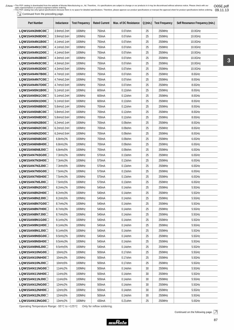
3
!Note • Please read rating and !CAUTION (for storage, operating, rating, soldering, mounting and handling) in this catalog to prevent smoking and/or burning, etc.• This catalog has only typical specifications because there is no space for detailed specifications. Therefore, please approve our product specifications or transact the approval sheet for product specifications before ordering.
87
• This PDF catalog is downloaded from the website of Murata Manufacturing co., ltd. Therefore, it’s specifications are subject to change or our products in it may be discontinued without advance notice. Please check with our sales representatives or product engineers before ordering.
• This PDF catalog has only typical specifications because there is no space for detailed specifications. Therefore, please approve our product specifications or transact the approval sheet for product specifications before ordering.
!Note O05E.pdf09.11.13
Continued from the preceding page.
Continued on the following page.
LQW15AN3N9C00p 3.9nH±0.2nH 100MHz 750mA 0.07ohm 25 250MHz 10.0GHz
LQW15AN3N9D00p 3.9nH±0.5nH 100MHz 750mA 0.07ohm 25 250MHz 10.0GHz
LQW15AN4N1B00p 4.1nH±0.1nH 100MHz 750mA 0.07ohm 25 250MHz 10.0GHz
LQW15AN4N1C00p 4.1nH±0.2nH 100MHz 750mA 0.07ohm 25 250MHz 10.0GHz
LQW15AN4N1D00p 4.1nH±0.5nH 100MHz 750mA 0.07ohm 25 250MHz 10.0GHz
LQW15AN4N3B00p 4.3nH±0.1nH 100MHz 750mA 0.07ohm 25 250MHz 10.0GHz
LQW15AN4N3C00p 4.3nH±0.2nH 100MHz 750mA 0.07ohm 25 250MHz 10.0GHz
Part Number Inductance Test Frequency Rated Current Max. of DC Resistance Q (min.) Test Frequency Self Resonance Frequency (min.)
LQW15AN4N3D00p 4.3nH±0.5nH 100MHz 750mA 0.07ohm 25 250MHz 10.0GHz
LQW15AN4N7B00p 4.7nH±0.1nH 100MHz 750mA 0.07ohm 25 250MHz 8.0GHz
LQW15AN4N7C00p 4.7nH±0.2nH 100MHz 750mA 0.07ohm 25 250MHz 8.0GHz
LQW15AN4N7D00p 4.7nH±0.5nH 100MHz 750mA 0.07ohm 25 250MHz 8.0GHz
LQW15AN5N1B00p 5.1nH±0.1nH 100MHz 600mA 0.12ohm 25 250MHz 8.0GHz
LQW15AN5N1C00p 5.1nH±0.2nH 100MHz 600mA 0.12ohm 25 250MHz 8.0GHz
LQW15AN5N1D00p 5.1nH±0.5nH 100MHz 600mA 0.12ohm 25 250MHz 8.0GHz
LQW15AN5N8B00p 5.8nH±0.1nH 100MHz 700mA 0.12ohm 25 250MHz 8.0GHz
LQW15AN5N8C00p 5.8nH±0.2nH 100MHz 700mA 0.12ohm 25 250MHz 8.0GHz
LQW15AN5N8D00p 5.8nH±0.5nH 100MHz 700mA 0.12ohm 25 250MHz 8.0GHz
LQW15AN6N2B00p 6.2nH±0.1nH 100MHz 700mA 0.09ohm 25 250MHz 8.0GHz
LQW15AN6N2C00p 6.2nH±0.2nH 100MHz 700mA 0.09ohm 25 250MHz 8.0GHz
LQW15AN6N2D00p 6.2nH±0.5nH 100MHz 700mA 0.09ohm 25 250MHz 8.0GHz
LQW15AN6N8G00p 6.8nH±2% 100MHz 700mA 0.09ohm 25 250MHz 6.0GHz
LQW15AN6N8H00p 6.8nH±3% 100MHz 700mA 0.09ohm 25 250MHz 6.0GHz
LQW15AN6N8J00p 6.8nH±5% 100MHz 700mA 0.09ohm 25 250MHz 6.0GHz
LQW15AN7N3G00p 7.3nH±2% 100MHz 570mA 0.13ohm 25 250MHz 6.0GHz
LQW15AN7N3H00p 7.3nH±3% 100MHz 570mA 0.13ohm 25 250MHz 6.0GHz
LQW15AN7N3J00p 7.3nH±5% 100MHz 570mA 0.13ohm 25 250MHz 6.0GHz
LQW15AN7N5G00p 7.5nH±2% 100MHz 570mA 0.13ohm 25 250MHz 6.0GHz
LQW15AN7N5H00p 7.5nH±3% 100MHz 570mA 0.13ohm 25 250MHz 6.0GHz
LQW15AN7N5J00p 7.5nH±5% 100MHz 570mA 0.13ohm 25 250MHz 6.0GHz
LQW15AN8N2G00p 8.2nH±2% 100MHz 540mA 0.14ohm 25 250MHz 5.5GHz
LQW15AN8N2H00p 8.2nH±3% 100MHz 540mA 0.14ohm 25 250MHz 5.5GHz
LQW15AN8N2J00p 8.2nH±5% 100MHz 540mA 0.14ohm 25 250MHz 5.5GHz
LQW15AN8N7G00p 8.7nH±2% 100MHz 540mA 0.14ohm 25 250MHz 5.5GHz
LQW15AN8N7H00p 8.7nH±3% 100MHz 540mA 0.14ohm 25 250MHz 5.5GHz
LQW15AN8N7J00p 8.7nH±5% 100MHz 540mA 0.14ohm 25 250MHz 5.5GHz
LQW15AN9N1G00p 9.1nH±2% 100MHz 540mA 0.14ohm 25 250MHz 5.5GHz
LQW15AN9N1H00p 9.1nH±3% 100MHz 540mA 0.14ohm 25 250MHz 5.5GHz
LQW15AN9N1J00p 9.1nH±5% 100MHz 540mA 0.14ohm 25 250MHz 5.5GHz
LQW15AN9N5G00p 9.5nH±2% 100MHz 540mA 0.14ohm 25 250MHz 5.5GHz
LQW15AN9N5H00p 9.5nH±3% 100MHz 540mA 0.14ohm 25 250MHz 5.5GHz
LQW15AN9N5J00p 9.5nH±5% 100MHz 540mA 0.14ohm 25 250MHz 5.5GHz
LQW15AN10NG00p 10nH±2% 100MHz 500mA 0.17ohm 25 250MHz 5.5GHz
LQW15AN10NH00p 10nH±3% 100MHz 500mA 0.17ohm 25 250MHz 5.5GHz
LQW15AN10NJ00p 10nH±5% 100MHz 500mA 0.17ohm 25 250MHz 5.5GHz
LQW15AN11NG00p 11nH±2% 100MHz 500mA 0.14ohm 30 250MHz 5.5GHz
LQW15AN11NH00p 11nH±3% 100MHz 500mA 0.14ohm 30 250MHz 5.5GHz
LQW15AN11NJ00p 11nH±5% 100MHz 500mA 0.14ohm 30 250MHz 5.5GHz
LQW15AN12NG00p 12nH±2% 100MHz 500mA 0.14ohm 30 250MHz 5.5GHz
Operating Temperature Range: -55°C to +125°C Only for reflow soldering.
LQW15AN12NH00p 12nH±3% 100MHz 500mA 0.14ohm 30 250MHz 5.5GHz
LQW15AN12NJ00p 12nH±5% 100MHz 500mA 0.14ohm 30 250MHz 5.5GHz
LQW15AN13NG00p 13nH±2% 100MHz 430mA 0.21ohm 25 250MHz 5.0GHz

3
!Note • Please read rating and !CAUTION (for storage, operating, rating, soldering, mounting and handling) in this catalog to prevent smoking and/or burning, etc.• This catalog has only typical specifications because there is no space for detailed specifications. Therefore, please approve our product specifications or transact the approval sheet for product specifications before ordering.
88
• This PDF catalog is downloaded from the website of Murata Manufacturing co., ltd. Therefore, it’s specifications are subject to change or our products in it may be discontinued without advance notice. Please check with our sales representatives or product engineers before ordering.
• This PDF catalog has only typical specifications because there is no space for detailed specifications. Therefore, please approve our product specifications or transact the approval sheet for product specifications before ordering.
!Note O05E.pdf09.11.13
Continued from the preceding page.
Continued on the following page.
Part Number Inductance Test Frequency Rated Current Max. of DC Resistance Q (min.) Test Frequency Self Resonance Frequency (min.)
LQW15AN13NH00p 13nH±3% 100MHz 430mA 0.21ohm 25 250MHz 5.0GHz
LQW15AN13NJ00p 13nH±5% 100MHz 430mA 0.21ohm 25 250MHz 5.0GHz
LQW15AN15NG00p 15nH±2% 100MHz 460mA 0.16ohm 30 250MHz 5.0GHz
LQW15AN15NH00p 15nH±3% 100MHz 460mA 0.16ohm 30 250MHz 5.0GHz
LQW15AN15NJ00p 15nH±5% 100MHz 460mA 0.16ohm 30 250MHz 5.0GHz
LQW15AN16NG00p 16nH±2% 100MHz 370mA 0.24ohm 25 250MHz 4.5GHz
LQW15AN16NH00p 16nH±3% 100MHz 370mA 0.24ohm 25 250MHz 4.5GHz
LQW15AN16NJ00p 16nH±5% 100MHz 370mA 0.24ohm 25 250MHz 4.5GHz
LQW15AN18NG00p 18nH±2% 100MHz 370mA 0.27ohm 25 250MHz 4.5GHz
LQW15AN18NH00p 18nH±3% 100MHz 370mA 0.27ohm 25 250MHz 4.5GHz
LQW15AN18NJ00p 18nH±5% 100MHz 370mA 0.27ohm 25 250MHz 4.5GHz
LQW15AN19NG00p 19nH±2% 100MHz 370mA 0.27ohm 25 250MHz 4.5GHz
LQW15AN19NH00p 19nH±3% 100MHz 370mA 0.27ohm 25 250MHz 4.5GHz
LQW15AN19NJ00p 19nH±5% 100MHz 370mA 0.27ohm 25 250MHz 4.5GHz
LQW15AN20NG00p 20nH±2% 100MHz 370mA 0.27ohm 25 250MHz 4.0GHz
LQW15AN20NH00p 20nH±3% 100MHz 370mA 0.27ohm 25 250MHz 4.0GHz
LQW15AN20NJ00p 20nH±5% 100MHz 370mA 0.27ohm 25 250MHz 4.0GHz
LQW15AN22NG00p 22nH±2% 100MHz 310mA 0.30ohm 25 250MHz 4.0GHz
LQW15AN22NH00p 22nH±3% 100MHz 310mA 0.30ohm 25 250MHz 4.0GHz
LQW15AN22NJ00p 22nH±5% 100MHz 310mA 0.30ohm 25 250MHz 4.0GHz
LQW15AN23NG00p 23nH±2% 100MHz 310mA 0.30ohm 25 250MHz 3.8GHz
LQW15AN23NH00p 23nH±3% 100MHz 310mA 0.30ohm 25 250MHz 3.8GHz
LQW15AN23NJ00p 23nH±5% 100MHz 310mA 0.30ohm 25 250MHz 3.8GHz
LQW15AN24NG00p 24nH±2% 100MHz 280mA 0.52ohm 25 250MHz 3.5GHz
LQW15AN24NH00p 24nH±3% 100MHz 280mA 0.52ohm 25 250MHz 3.5GHz
LQW15AN24NJ00p 24nH±5% 100MHz 280mA 0.52ohm 25 250MHz 3.5GHz
LQW15AN27NG00p 27nH±2% 100MHz 280mA 0.52ohm 25 250MHz 3.5GHz
LQW15AN27NH00p 27nH±3% 100MHz 280mA 0.52ohm 25 250MHz 3.5GHz
LQW15AN27NJ00p 27nH±5% 100MHz 280mA 0.52ohm 25 250MHz 3.5GHz
LQW15AN30NG00p 30nH±2% 100MHz 270mA 0.58ohm 25 250MHz 3.3GHz
LQW15AN30NH00p 30nH±3% 100MHz 270mA 0.58ohm 25 250MHz 3.3GHz
LQW15AN30NJ00p 30nH±5% 100MHz 270mA 0.58ohm 25 250MHz 3.3GHz
LQW15AN33NG00p 33nH±2% 100MHz 260mA 0.63ohm 25 250MHz 3.2GHz
LQW15AN33NH00p 33nH±3% 100MHz 260mA 0.63ohm 25 250MHz 3.2GHz
LQW15AN33NJ00p 33nH±5% 100MHz 260mA 0.63ohm 25 250MHz 3.2GHz
LQW15AN36NG00p 36nH±2% 100MHz 260mA 0.63ohm 25 250MHz 3.1GHz
LQW15AN36NH00p 36nH±3% 100MHz 260mA 0.63ohm 25 250MHz 3.1GHz
LQW15AN36NJ00p 36nH±5% 100MHz 260mA 0.63ohm 25 250MHz 3.1GHz
Operating Temperature Range: -55°C to +125°C Only for reflow soldering.
LQW15AN39NG00p 39nH±2% 100MHz 250mA 0.70ohm 25 250MHz 3.0GHz
LQW15AN39NH00p 39nH±3% 100MHz 250mA 0.70ohm 25 250MHz 3.0GHz
LQW15AN39NJ00p 39nH±5% 100MHz 250mA 0.70ohm 25 250MHz 3.0GHz
LQW15AN40NG00p 40nH±2% 100MHz 250mA 0.70ohm 25 250MHz 3.0GHz
LQW15AN40NH00p 40nH±3% 100MHz 250mA 0.70ohm 25 250MHz 3.0GHz
LQW15AN40NJ00p 40nH±5% 100MHz 250mA 0.70ohm 25 250MHz 3.0GHz
LQW15AN43NG00p 43nH±2% 100MHz 250mA 0.70ohm 25 250MHz 3.0GHz
LQW15AN43NH00p 43nH±3% 100MHz 250mA 0.70ohm 25 250MHz 3.0GHz
LQW15AN43NJ00p 43nH±5% 100MHz 250mA 0.70ohm 25 250MHz 3.0GHz
LQW15AN47NG00p 47nH±2% 100MHz 210mA 1.08ohm 25 200MHz 2.9GHz
LQW15AN47NH00p 47nH±3% 100MHz 210mA 1.08ohm 25 200MHz 2.9GHz
LQW15AN47NJ00p 47nH±5% 100MHz 210mA 1.08ohm 25 200MHz 2.9GHz
LQW15AN51NG00p 51nH±2% 100MHz 210mA 1.08ohm 25 200MHz 2.85GHz
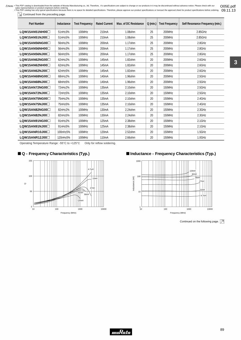
3
!Note • Please read rating and !CAUTION (for storage, operating, rating, soldering, mounting and handling) in this catalog to prevent smoking and/or burning, etc.• This catalog has only typical specifications because there is no space for detailed specifications. Therefore, please approve our product specifications or transact the approval sheet for product specifications before ordering.
89
• This PDF catalog is downloaded from the website of Murata Manufacturing co., ltd. Therefore, it’s specifications are subject to change or our products in it may be discontinued without advance notice. Please check with our sales representatives or product engineers before ordering.
• This PDF catalog has only typical specifications because there is no space for detailed specifications. Therefore, please approve our product specifications or transact the approval sheet for product specifications before ordering.
!Note O05E.pdf09.11.13
Continued from the preceding page.
Continued on the following page.
Part Number Inductance Test Frequency Rated Current Max. of DC Resistance Q (min.) Test Frequency Self Resonance Frequency (min.)
LQW15AN51NH00p 51nH±3% 100MHz 210mA 1.08ohm 25 200MHz 2.85GHz
LQW15AN51NJ00p 51nH±5% 100MHz 210mA 1.08ohm 25 200MHz 2.85GHz
LQW15AN56NG00p 56nH±2% 100MHz 200mA 1.17ohm 25 200MHz 2.8GHz
LQW15AN56NH00p 56nH±3% 100MHz 200mA 1.17ohm 25 200MHz 2.8GHz
LQW15AN56NJ00p 56nH±5% 100MHz 200mA 1.17ohm 25 200MHz 2.8GHz
LQW15AN62NG00p 62nH±2% 100MHz 145mA 1.82ohm 20 200MHz 2.6GHz
LQW15AN62NH00p 62nH±3% 100MHz 145mA 1.82ohm 20 200MHz 2.6GHz
LQW15AN62NJ00p 62nH±5% 100MHz 145mA 1.82ohm 20 200MHz 2.6GHz
LQW15AN68NG00p 68nH±2% 100MHz 140mA 1.96ohm 20 200MHz 2.5GHz
LQW15AN68NJ00p 68nH±5% 100MHz 140mA 1.96ohm 20 200MHz 2.5GHz
LQW15AN72NG00p 72nH±2% 100MHz 135mA 2.10ohm 20 150MHz 2.5GHz
LQW15AN72NJ00p 72nH±5% 100MHz 135mA 2.10ohm 20 150MHz 2.5GHz
LQW15AN75NG00p 75nH±2% 100MHz 135mA 2.10ohm 20 150MHz 2.4GHz
LQW15AN75NJ00p 75nH±5% 100MHz 135mA 2.10ohm 20 150MHz 2.4GHz
LQW15AN82NG00p 82nH±2% 100MHz 130mA 2.24ohm 20 150MHz 2.3GHz
LQW15AN82NJ00p 82nH±5% 100MHz 130mA 2.24ohm 20 150MHz 2.3GHz
LQW15AN91NG00p 91nH±2% 100MHz 125mA 2.38ohm 20 150MHz 2.1GHz
LQW15AN91NJ00p 91nH±5% 100MHz 125mA 2.38ohm 20 150MHz 2.1GHz
LQW15ANR10J00p 100nH±5% 100MHz 120mA 2.52ohm 20 150MHz 1.5GHz
LQW15ANR12J00p 120nH±5% 100MHz 110mA 2.66ohm 20 150MHz 1.0GHz
Operating Temperature Range: -55°C to +125°C Only for reflow soldering.
0
50
100
150
10 100 1000 10000
Q
Frequency (MHz)
4.7nH
10nH
27nH
82nH
120nH
56nH
Q - Frequency Characteristics (Typ.)
1
10
100
1000
10
Indu
ctan
ce (
nH)
100 1000 10000
Frequency (MHz)
120nH
82nH
56nH
27nH
10nH
4.7nH
Inductance - Frequency Characteristics (Typ.)
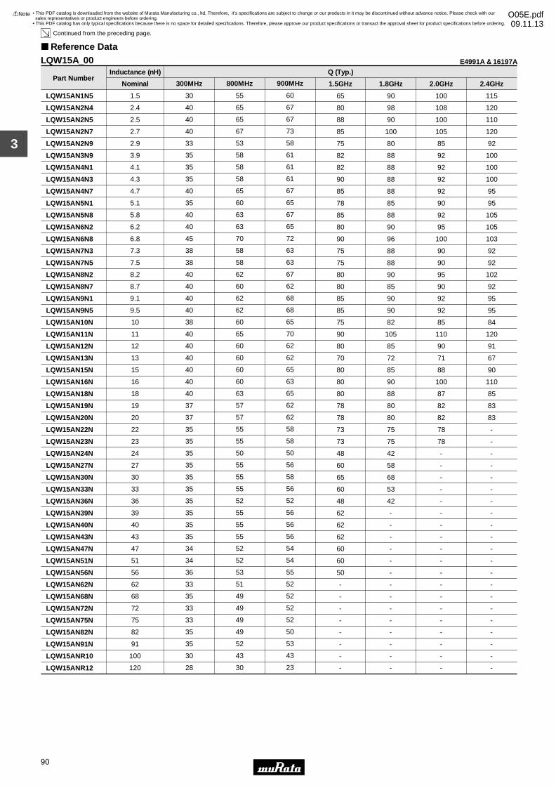
3
!Note • Please read rating and !CAUTION (for storage, operating, rating, soldering, mounting and handling) in this catalog to prevent smoking and/or burning, etc.• This catalog has only typical specifications because there is no space for detailed specifications. Therefore, please approve our product specifications or transact the approval sheet for product specifications before ordering.
90
• This PDF catalog is downloaded from the website of Murata Manufacturing co., ltd. Therefore, it’s specifications are subject to change or our products in it may be discontinued without advance notice. Please check with our sales representatives or product engineers before ordering.
• This PDF catalog has only typical specifications because there is no space for detailed specifications. Therefore, please approve our product specifications or transact the approval sheet for product specifications before ordering.
!Note O05E.pdf09.11.13
Continued from the preceding page.
Reference Data
Part Number
LQW15AN1N5
LQW15AN2N4
LQW15AN2N5
LQW15AN2N7
LQW15AN2N9
LQW15AN3N9
LQW15AN4N1
LQW15AN4N3
LQW15AN4N7
LQW15AN5N1
LQW15AN5N8
LQW15AN6N2
LQW15AN6N8
LQW15AN7N3
LQW15AN7N5
LQW15AN8N2
LQW15AN8N7
LQW15AN9N1
LQW15AN9N5
LQW15AN10N
LQW15AN11N
LQW15AN12N
LQW15AN13N
LQW15AN15N
LQW15AN16N
LQW15AN18N
LQW15AN19N
LQW15AN20N
LQW15AN22N
LQW15AN23N
LQW15AN24N
LQW15AN27N
LQW15AN30N
LQW15AN33N
LQW15AN36N
LQW15AN39N
LQW15AN40N
LQW15AN43N
LQW15AN47N
LQW15AN51N
LQW15AN56N
LQW15AN62N
LQW15AN68N
LQW15AN72N
LQW15AN75N
LQW15AN82N
LQW15AN91N
LQW15ANR10
LQW15ANR12
1.5
2.4
2.5
2.7
2.9
3.9
4.1
4.3
4.7
5.1
5.8
6.2
6.8
7.3
7.5
8.2
8.7
9.1
9.5
10
11
12
13
15
16
18
19
20
22
23
24
27
30
33
36
39
40
43
47
51
56
62
68
72
75
82
91
100
120
Nominal
30
40
40
40
33
35
35
35
40
35
40
40
45
38
38
40
40
40
40
38
40
40
40
40
40
40
37
37
35
35
35
35
35
35
35
35
35
35
34
34
36
33
35
33
33
35
35
30
28
300MHz
55
65
65
67
53
58
58
58
65
60
63
63
70
58
58
62
60
62
62
60
65
60
60
60
60
63
57
57
55
55
50
55
55
55
52
55
55
55
52
52
53
51
49
49
49
49
52
43
30
800MHz
60
67
67
73
58
61
61
61
67
65
67
65
72
63
63
67
62
68
68
65
70
62
62
65
63
65
62
62
58
58
50
56
58
56
52
56
56
56
54
54
55
52
52
52
52
50
53
43
23
900MHz
65
80
88
85
75
82
82
90
85
78
85
80
90
75
75
80
80
85
85
75
90
80
70
80
80
80
78
78
73
73
48
60
65
60
48
62
62
62
60
60
50
-
-
-
-
-
-
-
-
1.5GHz
90
98
90
100
80
88
88
88
88
85
88
90
96
88
88
90
85
90
90
82
105
85
72
85
90
88
80
80
75
75
42
58
68
53
42
-
-
-
-
-
-
-
-
-
-
-
-
-
-
1.8GHz
100
108
100
105
85
92
92
92
92
90
92
95
100
90
90
95
90
92
92
85
110
90
71
88
100
87
82
82
78
78
-
-
-
-
-
-
-
-
-
-
-
-
-
-
-
-
-
-
-
2.0GHz
115
120
110
120
92
100
100
100
95
95
105
105
103
92
92
102
92
95
95
84
120
91
67
90
110
85
83
83
-
-
-
-
-
-
-
-
-
-
-
-
-
-
-
-
-
-
-
-
-
2.4GHz
Inductance (nH) Q (Typ.)
E4991A & 16197ALQW15A_00
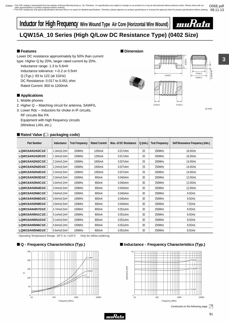
3
!Note • Please read rating and !CAUTION (for storage, operating, rating, soldering, mounting and handling) in this catalog to prevent smoking and/or burning, etc.• This catalog has only typical specifications because there is no space for detailed specifications. Therefore, please approve our product specifications or transact the approval sheet for product specifications before ordering.
91
• This PDF catalog is downloaded from the website of Murata Manufacturing co., ltd. Therefore, it’s specifications are subject to change or our products in it may be discontinued without advance notice. Please check with our sales representatives or product engineers before ordering.
• This PDF catalog has only typical specifications because there is no space for detailed specifications. Therefore, please approve our product specifications or transact the approval sheet for product specifications before ordering.
!Note O05E.pdf09.11.13
Inductor for High Frequency Wire Wound Type Air Core (Horizontal Wire Wound)
LQW15A_10 Series (High Q/Low DC Resistance Type) (0402 Size)
Lower DC resistance approximately by 50% than current type. Higher Q by 20%, larger rated current by 20%. Inductance range: 1.3 to 5.6nH Inductance tolerance: +-0.2 or 0.5nH Q (Typ.): 83 to 122 (at 1GHz) DC Resistance: 0.017 to 0.051 ohm Rated Current: 800 to 1200mA
Applications1. Mobile phones2. Higher Q -- Matching circuit for antenna, SAWFIL3. Lower Rdc -- Inductors for choke in IF circuits, RF circuits like PA Equipment with high frequency circuits (Wireless LAN, etc.)
Dimension Features
Rated Value (p: packaging code)
Continued on the following page.
0.6±0.11.0±0.1
0.5±
0.1
0.10
±0.0
5
0.2±0.1 0.2±0.1
(in mm)
0.5±0.1
Part Number Inductance Test Frequency Rated Current Max. of DC Resistance Q (min.) Test Frequency Self Resonance Frequency (min.)
LQW15AN1N3C10p 1.3nH±0.2nH 100MHz 1200mA 0.017ohm 20 250MHz 16.0GHz
LQW15AN1N3D10p 1.3nH±0.5nH 100MHz 1200mA 0.017ohm 20 250MHz 16.0GHz
LQW15AN2N2C10p 2.2nH±0.2nH 100MHz 1000mA 0.027ohm 25 250MHz 14.0GHz
LQW15AN2N2D10p 2.2nH±0.5nH 100MHz 1000mA 0.027ohm 25 250MHz 14.0GHz
LQW15AN2N4D10p 2.4nH±0.5nH 100MHz 1000mA 0.027ohm 25 250MHz 14.0GHz
LQW15AN3N3D10p 3.3nH±0.5nH 100MHz 900mA 0.040ohm 30 250MHz 12.0GHz
LQW15AN3N4C10p 3.4nH±0.2nH 100MHz 900mA 0.040ohm 30 250MHz 12.0GHz
LQW15AN3N4D10p 3.4nH±0.5nH 100MHz 900mA 0.040ohm 30 250MHz 12.0GHz
LQW15AN3N6C10p 3.6nH±0.2nH 100MHz 900mA 0.040ohm 30 250MHz 9.5GHz
LQW15AN3N6D10p 3.6nH±0.5nH 100MHz 900mA 0.040ohm 30 250MHz 9.5GHz
LQW15AN3N9D10p 3.9nH±0.5nH 100MHz 900mA 0.040ohm 30 250MHz 7.0GHz
LQW15AN4N7D10p 4.7nH±0.5nH 100MHz 800mA 0.051ohm 30 250MHz 8.0GHz
LQW15AN5N1C10p 5.1nH±0.2nH 100MHz 800mA 0.051ohm 30 250MHz 8.0GHz
LQW15AN5N1D10p 5.1nH±0.5nH 100MHz 800mA 0.051ohm 30 250MHz 8.0GHz
LQW15AN5N6C10p 5.6nH±0.2nH 100MHz 800mA 0.051ohm 30 250MHz 8.0GHz
LQW15AN5N6D10p 5.6nH±0.5nH 100MHz 800mA 0.051ohm 30 250MHz 8.0GHz
Operating Temperature Range: -55°C to +125°C Only for reflow soldering.
0
50
100
150
200
250
10 100 1000 10000
Frequency (MHz)
Q
5.6nH
3.6nH
1.3nH
Q - Frequency Characteristics (Typ.)
110 100 1000 10000
Frequency (MHz)
Indu
ctan
ce (
nH)
10
5.6nH
3.6nH
1.3nH
Inductance - Frequency Characteristics (Typ.)
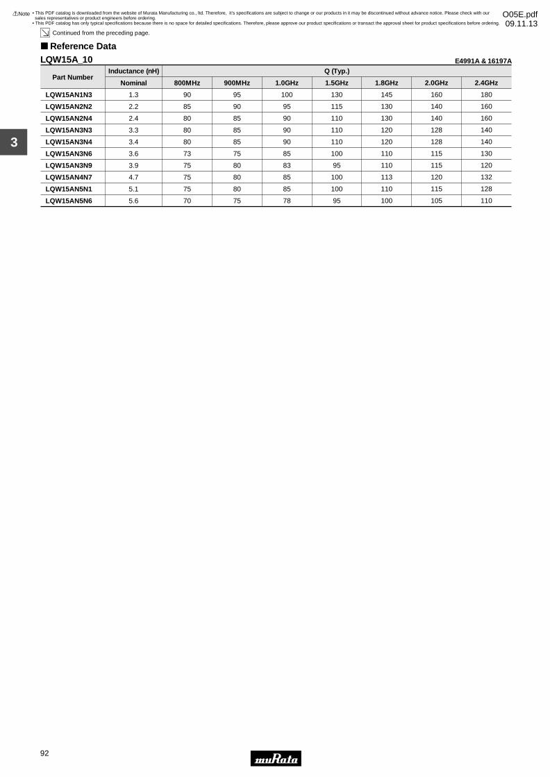
3
!Note • Please read rating and !CAUTION (for storage, operating, rating, soldering, mounting and handling) in this catalog to prevent smoking and/or burning, etc.• This catalog has only typical specifications because there is no space for detailed specifications. Therefore, please approve our product specifications or transact the approval sheet for product specifications before ordering.
92
• This PDF catalog is downloaded from the website of Murata Manufacturing co., ltd. Therefore, it’s specifications are subject to change or our products in it may be discontinued without advance notice. Please check with our sales representatives or product engineers before ordering.
• This PDF catalog has only typical specifications because there is no space for detailed specifications. Therefore, please approve our product specifications or transact the approval sheet for product specifications before ordering.
!Note O05E.pdf09.11.13
Continued from the preceding page.
Reference Data
Part Number
LQW15AN1N3
LQW15AN2N2
LQW15AN2N4
LQW15AN3N3
LQW15AN3N4
LQW15AN3N6
LQW15AN3N9
LQW15AN4N7
LQW15AN5N1
LQW15AN5N6
1.3
2.2
2.4
3.3
3.4
3.6
3.9
4.7
5.1
5.6
Nominal
90
85
80
80
80
73
75
75
75
70
800MHz
95
90
85
85
85
75
80
80
80
75
900MHz
100
95
90
90
90
85
83
85
85
78
1.0GHz
130
115
110
110
110
100
95
100
100
95
1.5GHz
145
130
130
120
120
110
110
113
110
100
1.8GHz
160
140
140
128
128
115
115
120
115
105
2.0GHz
180
160
160
140
140
130
120
132
128
110
2.4GHz
Inductance (nH) Q (Typ.)E4991A & 16197ALQW15A_10
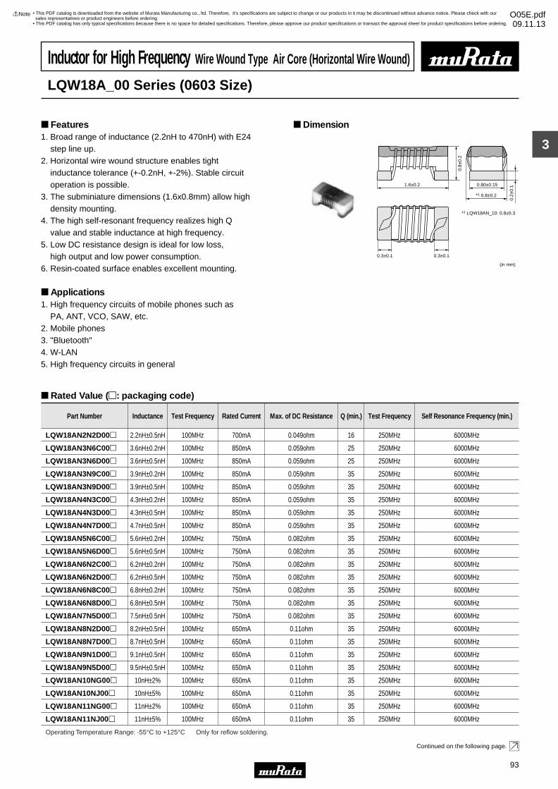
3
!Note • Please read rating and !CAUTION (for storage, operating, rating, soldering, mounting and handling) in this catalog to prevent smoking and/or burning, etc.• This catalog has only typical specifications because there is no space for detailed specifications. Therefore, please approve our product specifications or transact the approval sheet for product specifications before ordering.
93
• This PDF catalog is downloaded from the website of Murata Manufacturing co., ltd. Therefore, it’s specifications are subject to change or our products in it may be discontinued without advance notice. Please check with our sales representatives or product engineers before ordering.
• This PDF catalog has only typical specifications because there is no space for detailed specifications. Therefore, please approve our product specifications or transact the approval sheet for product specifications before ordering.
!Note O05E.pdf09.11.13
Inductor for High Frequency Wire Wound Type Air Core (Horizontal Wire Wound)
LQW18A_00 Series (0603 Size)
1. Broad range of inductance (2.2nH to 470nH) with E24 step line up.2. Horizontal wire wound structure enables tight inductance tolerance (+-0.2nH, +-2%). Stable circuit operation is possible.3. The subminiature dimensions (1.6x0.8mm) allow high density mounting.4. The high self-resonant frequency realizes high Q value and stable inductance at high frequency.5. Low DC resistance design is ideal for low loss, high output and low power consumption.6. Resin-coated surface enables excellent mounting.
Applications1. High frequency circuits of mobile phones such as PA, ANT, VCO, SAW, etc.2. Mobile phones3. "Bluetooth"4. W-LAN5. High frequency circuits in general
Dimension Features
Rated Value (p: packaging code)
Continued on the following page.
1.6±0.2
*1 0.8±0.2
0.80±0.15
(in mm)
0.8±
0.2
0.2±
0.1
0.3±0.1 0.3±0.1
*1 LQW18AN_10: 0.8±0.3
Part Number Inductance Test Frequency Rated Current Max. of DC Resistance Q (min.) Test Frequency Self Resonance Frequency (min.)
LQW18AN2N2D00p 2.2nH±0.5nH 100MHz 700mA 0.049ohm 16 250MHz 6000MHz
LQW18AN3N6C00p 3.6nH±0.2nH 100MHz 850mA 0.059ohm 25 250MHz 6000MHz
LQW18AN3N6D00p 3.6nH±0.5nH 100MHz 850mA 0.059ohm 25 250MHz 6000MHz
LQW18AN3N9C00p 3.9nH±0.2nH 100MHz 850mA 0.059ohm 35 250MHz 6000MHz
LQW18AN3N9D00p 3.9nH±0.5nH 100MHz 850mA 0.059ohm 35 250MHz 6000MHz
LQW18AN4N3C00p 4.3nH±0.2nH 100MHz 850mA 0.059ohm 35 250MHz 6000MHz
LQW18AN4N3D00p 4.3nH±0.5nH 100MHz 850mA 0.059ohm 35 250MHz 6000MHz
LQW18AN4N7D00p 4.7nH±0.5nH 100MHz 850mA 0.059ohm 35 250MHz 6000MHz
LQW18AN5N6C00p 5.6nH±0.2nH 100MHz 750mA 0.082ohm 35 250MHz 6000MHz
LQW18AN5N6D00p 5.6nH±0.5nH 100MHz 750mA 0.082ohm 35 250MHz 6000MHz
LQW18AN6N2C00p 6.2nH±0.2nH 100MHz 750mA 0.082ohm 35 250MHz 6000MHz
LQW18AN6N2D00p 6.2nH±0.5nH 100MHz 750mA 0.082ohm 35 250MHz 6000MHz
LQW18AN6N8C00p 6.8nH±0.2nH 100MHz 750mA 0.082ohm 35 250MHz 6000MHz
LQW18AN6N8D00p 6.8nH±0.5nH 100MHz 750mA 0.082ohm 35 250MHz 6000MHz
LQW18AN7N5D00p 7.5nH±0.5nH 100MHz 750mA 0.082ohm 35 250MHz 6000MHz
LQW18AN8N2D00p 8.2nH±0.5nH 100MHz 650mA 0.11ohm 35 250MHz 6000MHz
LQW18AN8N7D00p 8.7nH±0.5nH 100MHz 650mA 0.11ohm 35 250MHz 6000MHz
LQW18AN9N1D00p 9.1nH±0.5nH 100MHz 650mA 0.11ohm 35 250MHz 6000MHz
LQW18AN9N5D00p 9.5nH±0.5nH 100MHz 650mA 0.11ohm 35 250MHz 6000MHz
LQW18AN10NG00p 10nH±2% 100MHz 650mA 0.11ohm 35 250MHz 6000MHz
LQW18AN10NJ00p 10nH±5% 100MHz 650mA 0.11ohm 35 250MHz 6000MHz
LQW18AN11NG00p 11nH±2% 100MHz 650mA 0.11ohm 35 250MHz 6000MHz
LQW18AN11NJ00p 11nH±5% 100MHz 650mA 0.11ohm 35 250MHz 6000MHz
Operating Temperature Range: -55°C to +125°C Only for reflow soldering.
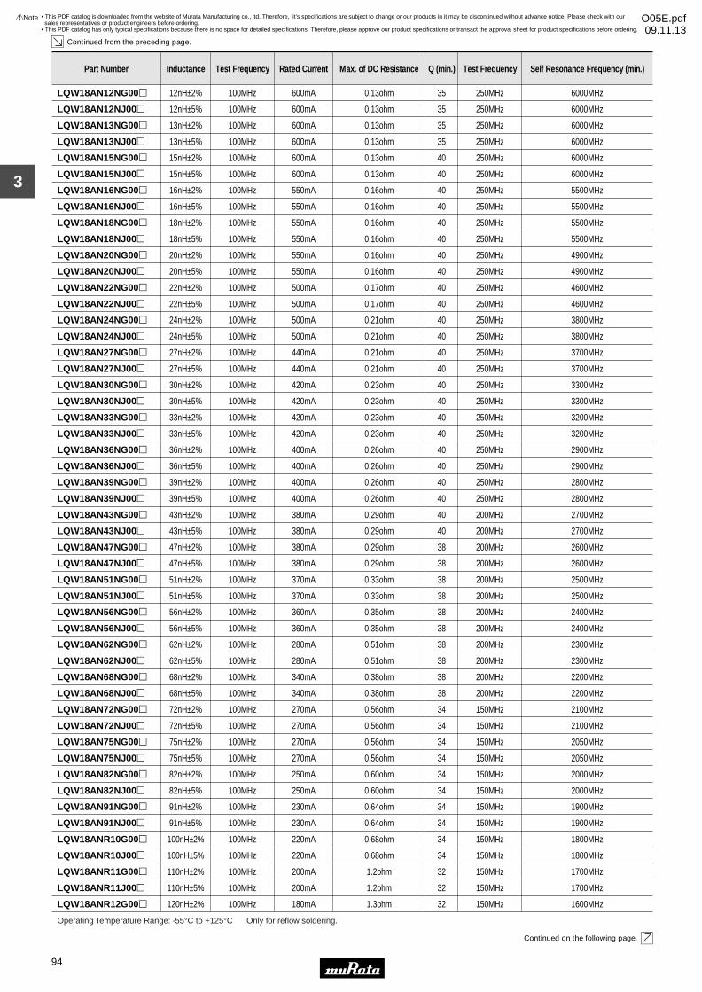
3
!Note • Please read rating and !CAUTION (for storage, operating, rating, soldering, mounting and handling) in this catalog to prevent smoking and/or burning, etc.• This catalog has only typical specifications because there is no space for detailed specifications. Therefore, please approve our product specifications or transact the approval sheet for product specifications before ordering.
94
• This PDF catalog is downloaded from the website of Murata Manufacturing co., ltd. Therefore, it’s specifications are subject to change or our products in it may be discontinued without advance notice. Please check with our sales representatives or product engineers before ordering.
• This PDF catalog has only typical specifications because there is no space for detailed specifications. Therefore, please approve our product specifications or transact the approval sheet for product specifications before ordering.
!Note O05E.pdf09.11.13
Continued from the preceding page.
Continued on the following page.
Part Number Inductance Test Frequency Rated Current Max. of DC Resistance Q (min.) Test Frequency Self Resonance Frequency (min.)
LQW18AN12NG00p 12nH±2% 100MHz 600mA 0.13ohm 35 250MHz 6000MHz
LQW18AN12NJ00p 12nH±5% 100MHz 600mA 0.13ohm 35 250MHz 6000MHz
LQW18AN13NG00p 13nH±2% 100MHz 600mA 0.13ohm 35 250MHz 6000MHz
LQW18AN13NJ00p 13nH±5% 100MHz 600mA 0.13ohm 35 250MHz 6000MHz
LQW18AN15NG00p 15nH±2% 100MHz 600mA 0.13ohm 40 250MHz 6000MHz
LQW18AN15NJ00p 15nH±5% 100MHz 600mA 0.13ohm 40 250MHz 6000MHz
LQW18AN16NG00p 16nH±2% 100MHz 550mA 0.16ohm 40 250MHz 5500MHz
LQW18AN16NJ00p 16nH±5% 100MHz 550mA 0.16ohm 40 250MHz 5500MHz
LQW18AN18NG00p 18nH±2% 100MHz 550mA 0.16ohm 40 250MHz 5500MHz
LQW18AN18NJ00p 18nH±5% 100MHz 550mA 0.16ohm 40 250MHz 5500MHz
LQW18AN20NG00p 20nH±2% 100MHz 550mA 0.16ohm 40 250MHz 4900MHz
LQW18AN20NJ00p 20nH±5% 100MHz 550mA 0.16ohm 40 250MHz 4900MHz
LQW18AN22NG00p 22nH±2% 100MHz 500mA 0.17ohm 40 250MHz 4600MHz
LQW18AN22NJ00p 22nH±5% 100MHz 500mA 0.17ohm 40 250MHz 4600MHz
LQW18AN24NG00p 24nH±2% 100MHz 500mA 0.21ohm 40 250MHz 3800MHz
LQW18AN24NJ00p 24nH±5% 100MHz 500mA 0.21ohm 40 250MHz 3800MHz
LQW18AN27NG00p 27nH±2% 100MHz 440mA 0.21ohm 40 250MHz 3700MHz
LQW18AN27NJ00p 27nH±5% 100MHz 440mA 0.21ohm 40 250MHz 3700MHz
LQW18AN30NG00p 30nH±2% 100MHz 420mA 0.23ohm 40 250MHz 3300MHz
LQW18AN30NJ00p 30nH±5% 100MHz 420mA 0.23ohm 40 250MHz 3300MHz
LQW18AN33NG00p 33nH±2% 100MHz 420mA 0.23ohm 40 250MHz 3200MHz
LQW18AN33NJ00p 33nH±5% 100MHz 420mA 0.23ohm 40 250MHz 3200MHz
LQW18AN36NG00p 36nH±2% 100MHz 400mA 0.26ohm 40 250MHz 2900MHz
LQW18AN36NJ00p 36nH±5% 100MHz 400mA 0.26ohm 40 250MHz 2900MHz
LQW18AN39NG00p 39nH±2% 100MHz 400mA 0.26ohm 40 250MHz 2800MHz
LQW18AN39NJ00p 39nH±5% 100MHz 400mA 0.26ohm 40 250MHz 2800MHz
LQW18AN43NG00p 43nH±2% 100MHz 380mA 0.29ohm 40 200MHz 2700MHz
LQW18AN43NJ00p 43nH±5% 100MHz 380mA 0.29ohm 40 200MHz 2700MHz
LQW18AN47NG00p 47nH±2% 100MHz 380mA 0.29ohm 38 200MHz 2600MHz
LQW18AN47NJ00p 47nH±5% 100MHz 380mA 0.29ohm 38 200MHz 2600MHz
LQW18AN51NG00p 51nH±2% 100MHz 370mA 0.33ohm 38 200MHz 2500MHz
LQW18AN51NJ00p 51nH±5% 100MHz 370mA 0.33ohm 38 200MHz 2500MHz
LQW18AN56NG00p 56nH±2% 100MHz 360mA 0.35ohm 38 200MHz 2400MHz
LQW18AN56NJ00p 56nH±5% 100MHz 360mA 0.35ohm 38 200MHz 2400MHz
LQW18AN62NG00p 62nH±2% 100MHz 280mA 0.51ohm 38 200MHz 2300MHz
LQW18AN62NJ00p 62nH±5% 100MHz 280mA 0.51ohm 38 200MHz 2300MHz
LQW18AN68NG00p 68nH±2% 100MHz 340mA 0.38ohm 38 200MHz 2200MHz
LQW18AN68NJ00p 68nH±5% 100MHz 340mA 0.38ohm 38 200MHz 2200MHz
LQW18AN72NG00p 72nH±2% 100MHz 270mA 0.56ohm 34 150MHz 2100MHz
LQW18AN72NJ00p 72nH±5% 100MHz 270mA 0.56ohm 34 150MHz 2100MHz
LQW18AN75NG00p 75nH±2% 100MHz 270mA 0.56ohm 34 150MHz 2050MHz
Operating Temperature Range: -55°C to +125°C Only for reflow soldering.
LQW18AN75NJ00p 75nH±5% 100MHz 270mA 0.56ohm 34 150MHz 2050MHz
LQW18AN82NG00p 82nH±2% 100MHz 250mA 0.60ohm 34 150MHz 2000MHz
LQW18AN82NJ00p 82nH±5% 100MHz 250mA 0.60ohm 34 150MHz 2000MHz
LQW18AN91NG00p 91nH±2% 100MHz 230mA 0.64ohm 34 150MHz 1900MHz
LQW18AN91NJ00p 91nH±5% 100MHz 230mA 0.64ohm 34 150MHz 1900MHz
LQW18ANR10G00p 100nH±2% 100MHz 220mA 0.68ohm 34 150MHz 1800MHz
LQW18ANR10J00p 100nH±5% 100MHz 220mA 0.68ohm 34 150MHz 1800MHz
LQW18ANR11G00p 110nH±2% 100MHz 200mA 1.2ohm 32 150MHz 1700MHz
LQW18ANR11J00p 110nH±5% 100MHz 200mA 1.2ohm 32 150MHz 1700MHz
LQW18ANR12G00p 120nH±2% 100MHz 180mA 1.3ohm 32 150MHz 1600MHz
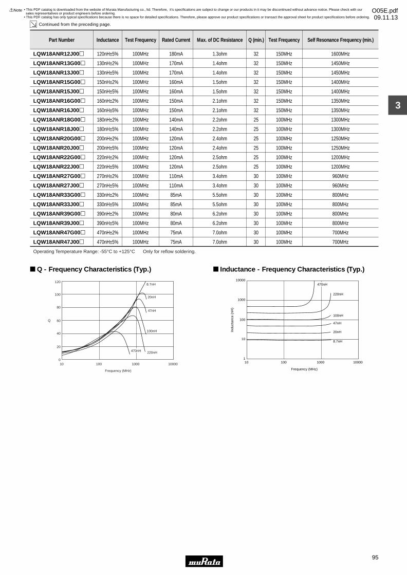
3
!Note • Please read rating and !CAUTION (for storage, operating, rating, soldering, mounting and handling) in this catalog to prevent smoking and/or burning, etc.• This catalog has only typical specifications because there is no space for detailed specifications. Therefore, please approve our product specifications or transact the approval sheet for product specifications before ordering.
95
• This PDF catalog is downloaded from the website of Murata Manufacturing co., ltd. Therefore, it’s specifications are subject to change or our products in it may be discontinued without advance notice. Please check with our sales representatives or product engineers before ordering.
• This PDF catalog has only typical specifications because there is no space for detailed specifications. Therefore, please approve our product specifications or transact the approval sheet for product specifications before ordering.
!Note O05E.pdf09.11.13
Continued from the preceding page.
Part Number Inductance Test Frequency Rated Current Max. of DC Resistance Q (min.) Test Frequency Self Resonance Frequency (min.)
LQW18ANR12J00p 120nH±5% 100MHz 180mA 1.3ohm 32 150MHz 1600MHz
LQW18ANR13G00p 130nH±2% 100MHz 170mA 1.4ohm 32 150MHz 1450MHz
LQW18ANR13J00p 130nH±5% 100MHz 170mA 1.4ohm 32 150MHz 1450MHz
LQW18ANR15G00p 150nH±2% 100MHz 160mA 1.5ohm 32 150MHz 1400MHz
LQW18ANR15J00p 150nH±5% 100MHz 160mA 1.5ohm 32 150MHz 1400MHz
LQW18ANR16G00p 160nH±2% 100MHz 150mA 2.1ohm 32 150MHz 1350MHz
LQW18ANR16J00p 160nH±5% 100MHz 150mA 2.1ohm 32 150MHz 1350MHz
LQW18ANR18G00p 180nH±2% 100MHz 140mA 2.2ohm 25 100MHz 1300MHz
LQW18ANR18J00p 180nH±5% 100MHz 140mA 2.2ohm 25 100MHz 1300MHz
LQW18ANR20G00p 200nH±2% 100MHz 120mA 2.4ohm 25 100MHz 1250MHz
LQW18ANR20J00p 200nH±5% 100MHz 120mA 2.4ohm 25 100MHz 1250MHz
LQW18ANR22G00p 220nH±2% 100MHz 120mA 2.5ohm 25 100MHz 1200MHz
LQW18ANR22J00p 220nH±5% 100MHz 120mA 2.5ohm 25 100MHz 1200MHz
LQW18ANR27G00p 270nH±2% 100MHz 110mA 3.4ohm 30 100MHz 960MHz
LQW18ANR27J00p 270nH±5% 100MHz 110mA 3.4ohm 30 100MHz 960MHz
LQW18ANR33G00p 330nH±2% 100MHz 85mA 5.5ohm 30 100MHz 800MHz
LQW18ANR33J00p 330nH±5% 100MHz 85mA 5.5ohm 30 100MHz 800MHz
LQW18ANR39G00p 390nH±2% 100MHz 80mA 6.2ohm 30 100MHz 800MHz
LQW18ANR39J00p 390nH±5% 100MHz 80mA 6.2ohm 30 100MHz 800MHz
LQW18ANR47G00p 470nH±2% 100MHz 75mA 7.0ohm 30 100MHz 700MHz
LQW18ANR47J00p 470nH±5% 100MHz 75mA 7.0ohm 30 100MHz 700MHz
Operating Temperature Range: -55°C to +125°C Only for reflow soldering.
120
100
80
60
40
20
010 100 1000 10000
Frequency (MHz)
Q
8.7nH
20nH
47nH
100nH
220nH470nH
Q - Frequency Characteristics (Typ.)
1000
10000
100
10
110 100 1000 10000
Frequency (MHz)
Indu
ctan
ce (
nH)
220nH
100nH
47nH
20nH
8.7nH
470nH
Inductance - Frequency Characteristics (Typ.)
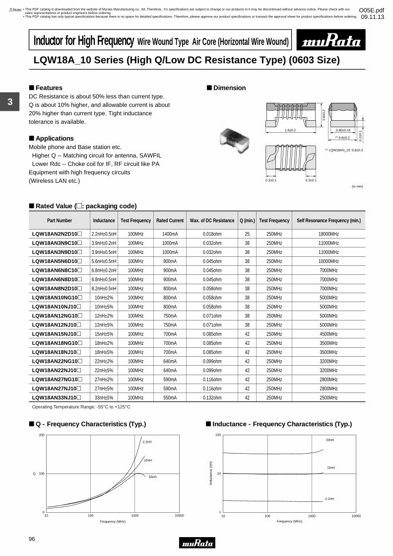
3
!Note • Please read rating and !CAUTION (for storage, operating, rating, soldering, mounting and handling) in this catalog to prevent smoking and/or burning, etc.• This catalog has only typical specifications because there is no space for detailed specifications. Therefore, please approve our product specifications or transact the approval sheet for product specifications before ordering.
96
• This PDF catalog is downloaded from the website of Murata Manufacturing co., ltd. Therefore, it’s specifications are subject to change or our products in it may be discontinued without advance notice. Please check with our sales representatives or product engineers before ordering.
• This PDF catalog has only typical specifications because there is no space for detailed specifications. Therefore, please approve our product specifications or transact the approval sheet for product specifications before ordering.
!Note O05E.pdf09.11.13
Inductor for High Frequency Wire Wound Type Air Core (Horizontal Wire Wound)
LQW18A_10 Series (High Q/Low DC Resistance Type) (0603 Size)
DC Resistance is about 50% less than current type.Q is about 10% higher, and allowable current is about 20% higher than current type. Tight inductance tolerance is available.
ApplicationsMobile phone and Base station etc. Higher Q -- Matching circuit for antenna, SAWFIL Lower Rdc -- Choke coil for IF, RF circuit like PAEquipment with high frequency circuits (Wireless LAN etc.)
Dimension Features
Rated Value (p: packaging code)
1.6±0.2
*1 0.8±0.2
0.80±0.15
(in mm)
0.8±
0.2
0.2±
0.1
0.3±0.1 0.3±0.1
*1 LQW18AN_10: 0.8±0.3
Part Number Inductance Test Frequency Rated Current Max. of DC Resistance Q (min.) Test Frequency Self Resonance Frequency (min.)
LQW18AN2N2D10p 2.2nH±0.5nH 100MHz 1400mA 0.018ohm 25 250MHz 18000MHz
LQW18AN3N9C10p 3.9nH±0.2nH 100MHz 1000mA 0.032ohm 38 250MHz 11000MHz
LQW18AN3N9D10p 3.9nH±0.5nH 100MHz 1000mA 0.032ohm 38 250MHz 11000MHz
LQW18AN5N6D10p 5.6nH±0.5nH 100MHz 900mA 0.045ohm 38 250MHz 10000MHz
LQW18AN6N8C10p 6.8nH±0.2nH 100MHz 900mA 0.045ohm 38 250MHz 7000MHz
LQW18AN6N8D10p 6.8nH±0.5nH 100MHz 900mA 0.045ohm 38 250MHz 7000MHz
LQW18AN8N2D10p 8.2nH±0.5nH 100MHz 800mA 0.058ohm 38 250MHz 7000MHz
LQW18AN10NG10p 10nH±2% 100MHz 800mA 0.058ohm 38 250MHz 5000MHz
LQW18AN10NJ10p 10nH±5% 100MHz 800mA 0.058ohm 38 250MHz 5000MHz
LQW18AN12NG10p 12nH±2% 100MHz 750mA 0.071ohm 38 250MHz 5000MHz
LQW18AN12NJ10p 12nH±5% 100MHz 750mA 0.071ohm 38 250MHz 5000MHz
LQW18AN15NJ10p 15nH±5% 100MHz 700mA 0.085ohm 42 250MHz 4500MHz
LQW18AN18NG10p 18nH±2% 100MHz 700mA 0.085ohm 42 250MHz 3500MHz
LQW18AN18NJ10p 18nH±5% 100MHz 700mA 0.085ohm 42 250MHz 3500MHz
LQW18AN22NG10p 22nH±2% 100MHz 640mA 0.099ohm 42 250MHz 3200MHz
LQW18AN22NJ10p 22nH±5% 100MHz 640mA 0.099ohm 42 250MHz 3200MHz
LQW18AN27NG10p 27nH±2% 100MHz 590mA 0.116ohm 42 250MHz 2800MHz
LQW18AN27NJ10p 27nH±5% 100MHz 590mA 0.116ohm 42 250MHz 2800MHz
LQW18AN33NJ10p 33nH±5% 100MHz 550mA 0.132ohm 42 250MHz 2500MHz
Operating Temperature Range: -55°C to +125°C
Q
Frequency (MHz)
0
100
200
10 100 1000 10000
2.2nH
10nH
33nH
Q - Frequency Characteristics (Typ.)
1
10
100
10 100 1000 10000
Frequency (MHz)
Indu
ctan
ce (
nH)
2.2nH
10nH
33nH
Inductance - Frequency Characteristics (Typ.)
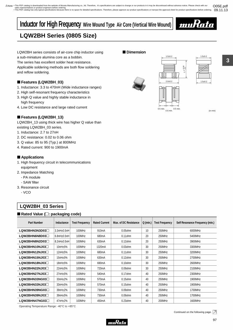
3
!Note • Please read rating and !CAUTION (for storage, operating, rating, soldering, mounting and handling) in this catalog to prevent smoking and/or burning, etc.• This catalog has only typical specifications because there is no space for detailed specifications. Therefore, please approve our product specifications or transact the approval sheet for product specifications before ordering.
97
• This PDF catalog is downloaded from the website of Murata Manufacturing co., ltd. Therefore, it’s specifications are subject to change or our products in it may be discontinued without advance notice. Please check with our sales representatives or product engineers before ordering.
• This PDF catalog has only typical specifications because there is no space for detailed specifications. Therefore, please approve our product specifications or transact the approval sheet for product specifications before ordering.
!Note O05E.pdf09.11.13
Inductor for High Frequency Wire Wound Type Air Core (Vertical Wire Wound)
LQW2BH Series (0805 Size)
LQW2BH series consists of air-core chip inductor using a sub-miniature alumina core as a bobbin.The series has excellent solder heat resistance.Applicable soldering methods are both flow solderingand reflow soldering.
Features (LQW2BH_03)1. Inductance: 3.3 to 470nH (Wide inductance ranges)2. High self-resonant frequency characteristics3. High Q value and highly stable inductance in high frequency4. Low DC resistance and large rated current
Features (LQW2BH_13)LQW2BH_13 using thick wire has higher Q value than existing LQW2BH_03 series.1. Inductance: 2.7 to 27nH2. DC resistance: 0.02 to 0.06 ohm3. Q value: 85 to 95 (Typ.) at 800MHz4. Rated current: 900 to 1900mA
Applications1. High frequency circuit in telecommunications equipment2. Impedance Matching - PA module - SAW filter3. Resonance circuit - VCO
Dimension
Rated Value (p: packaging code)
Continued on the following page.
LQW2BH_03 Series
2.0±0.2
1.5±0.2
0.5 min.0.5 min.0.5 min.
1.5±0.2
1.5±0.2
(in mm)
1.7
+0.
08-0
.1
Part Number Inductance Test Frequency Rated Current Max. of DC Resistance Q (min.) Test Frequency Self Resonance Frequency (min.)
LQW2BHN3N3D03p 3.3nH±0.5nH 100MHz 910mA 0.05ohm 10 250MHz 6000MHz
LQW2BHN6N8D03p 6.8nH±0.5nH 100MHz 680mA 0.11ohm 20 250MHz 5400MHz
LQW2BHN8N2D03p 8.2nH±0.5nH 100MHz 630mA 0.12ohm 20 250MHz 3900MHz
LQW2BHN10NJ03p 10nH±5% 100MHz 1320mA 0.03ohm 30 250MHz 3300MHz
LQW2BHN12NJ03p 12nH±5% 100MHz 680mA 0.11ohm 30 250MHz 3200MHz
LQW2BHN15NJ03p 15nH±5% 100MHz 630mA 0.12ohm 30 250MHz 2700MHz
LQW2BHN18NJ03p 18nH±5% 100MHz 690mA 0.10ohm 30 250MHz 2600MHz
LQW2BHN22NJ03p 22nH±5% 100MHz 720mA 0.09ohm 30 250MHz 2100MHz
LQW2BHN27NJ03p 27nH±5% 100MHz 540mA 0.17ohm 40 250MHz 2300MHz
LQW2BHN33NG03p 33nH±2% 100MHz 570mA 0.15ohm 40 250MHz 1900MHz
LQW2BHN33NJ03p 33nH±5% 100MHz 570mA 0.15ohm 40 250MHz 1900MHz
LQW2BHN39NG03p 39nH±2% 100MHz 730mA 0.09ohm 40 250MHz 1700MHz
LQW2BHN39NJ03p 39nH±5% 100MHz 730mA 0.09ohm 40 250MHz 1700MHz
LQW2BHN47NG03p 47nH±2% 100MHz 450mA 0.23ohm 40 200MHz 1600MHz
Operating Temperature Range: -40°C to +85°C
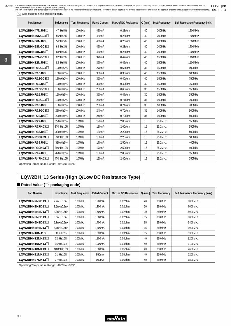
3
!Note • Please read rating and !CAUTION (for storage, operating, rating, soldering, mounting and handling) in this catalog to prevent smoking and/or burning, etc.• This catalog has only typical specifications because there is no space for detailed specifications. Therefore, please approve our product specifications or transact the approval sheet for product specifications before ordering.
98
• This PDF catalog is downloaded from the website of Murata Manufacturing co., ltd. Therefore, it’s specifications are subject to change or our products in it may be discontinued without advance notice. Please check with our sales representatives or product engineers before ordering.
• This PDF catalog has only typical specifications because there is no space for detailed specifications. Therefore, please approve our product specifications or transact the approval sheet for product specifications before ordering.
!Note O05E.pdf09.11.13
Continued from the preceding page.
LQW2BH_13 Series (High Q/Low DC Resistance Type)
Rated Value (p: packaging code)
LQW2BHN47NJ03p 47nH±5% 100MHz 450mA 0.23ohm 40 200MHz 1600MHz
LQW2BHN56NG03p 56nH±2% 100MHz 430mA 0.26ohm 40 200MHz 1500MHz
LQW2BHN56NJ03p 56nH±5% 100MHz 430mA 0.26ohm 40 200MHz 1500MHz
LQW2BHN68NG03p 68nH±2% 100MHz 460mA 0.23ohm 40 200MHz 1200MHz
LQW2BHN68NJ03p 68nH±5% 100MHz 460mA 0.23ohm 40 200MHz 1200MHz
LQW2BHN82NG03p 82nH±2% 100MHz 320mA 0.42ohm 40 150MHz 1100MHz
LQW2BHN82NJ03p 82nH±5% 100MHz 320mA 0.42ohm 40 150MHz 1100MHz
LQW2BHNR10G03p 100nH±2% 100MHz 270mA 0.55ohm 35 150MHz 900MHz
LQW2BHNR10J03p 100nH±5% 100MHz 350mA 0.38ohm 40 150MHz 900MHz
LQW2BHNR12G03p 120nH±2% 100MHz 320mA 0.40ohm 40 150MHz 750MHz
Part Number Inductance Test Frequency Rated Current Max. of DC Resistance Q (min.) Test Frequency Self Resonance Frequency (min.)
LQW2BHNR12J03p 120nH±5% 100MHz 320mA 0.40ohm 40 150MHz 750MHz
LQW2BHNR15G03p 150nH±2% 100MHz 260mA 0.68ohm 30 150MHz 350MHz
LQW2BHNR15J03p 150nH±5% 100MHz 390mA 0.47ohm 30 150MHz 350MHz
LQW2BHNR18G03p 180nH±2% 100MHz 250mA 0.71ohm 35 100MHz 700MHz
LQW2BHNR18J03p 180nH±5% 100MHz 250mA 0.71ohm 35 100MHz 700MHz
LQW2BHNR22G03p 220nH±2% 100MHz 240mA 0.70ohm 35 100MHz 500MHz
LQW2BHNR22J03p 220nH±5% 100MHz 240mA 0.70ohm 35 100MHz 500MHz
LQW2BHNR27J03p 270nH±5% 10MHz 190mA 2.00ohm 15 25.2MHz 550MHz
LQW2BHNR27K03p 270nH±10% 10MHz 190mA 2.00ohm 15 25.2MHz 550MHz
LQW2BHNR33J03p 330nH±5% 10MHz 180mA 2.20ohm 15 25.2MHz 500MHz
LQW2BHNR33K03p 330nH±10% 10MHz 180mA 2.20ohm 15 25.2MHz 500MHz
LQW2BHNR39J03p 390nH±5% 10MHz 170mA 2.50ohm 15 25.2MHz 400MHz
LQW2BHNR39K03p 390nH±10% 10MHz 170mA 2.50ohm 15 25.2MHz 400MHz
LQW2BHNR47J03p 470nH±5% 10MHz 160mA 2.80ohm 15 25.2MHz 350MHz
LQW2BHNR47K03p 470nH±10% 10MHz 160mA 2.80ohm 15 25.2MHz 350MHz
Operating Temperature Range: -40°C to +85°C
Part Number Inductance Test Frequency Rated Current Max. of DC Resistance Q (min.) Test Frequency Self Resonance Frequency (min.)
LQW2BHN2N7D13p 2.7nH±0.5nH 100MHz 1900mA 0.02ohm 20 250MHz 6000MHz
LQW2BHN3N1D13p 3.1nH±0.5nH 100MHz 1800mA 0.02ohm 20 250MHz 6000MHz
LQW2BHN3N3D13p 3.3nH±0.5nH 100MHz 1700mA 0.02ohm 20 250MHz 6000MHz
LQW2BHN5N6D13p 5.6nH±0.5nH 100MHz 1500mA 0.02ohm 35 250MHz 6000MHz
LQW2BHN6N8D13p 6.8nH±0.5nH 100MHz 1400mA 0.02ohm 35 250MHz 5400MHz
LQW2BHN8N6D13p 8.6nH±0.5nH 100MHz 1300mA 0.03ohm 35 250MHz 3900MHz
LQW2BHN10NJ13p 10nH±5% 100MHz 1320mA 0.03ohm 35 250MHz 3300MHz
LQW2BHN12NK13p 12nH±10% 100MHz 1100mA 0.04ohm 40 250MHz 3200MHz
LQW2BHN15NK13p 15nH±10% 100MHz 1000mA 0.04ohm 40 250MHz 3100MHz
LQW2BHN18NK13p 18.8nH±10% 100MHz 1000mA 0.05ohm 40 250MHz 2600MHz
LQW2BHN21NK13p 21nH±10% 100MHz 950mA 0.05ohm 40 250MHz 2200MHz
LQW2BHN27NK13p 27nH±10% 100MHz 900mA 0.06ohm 40 250MHz 1800MHz
Operating Temperature Range: -40°C to +85°C
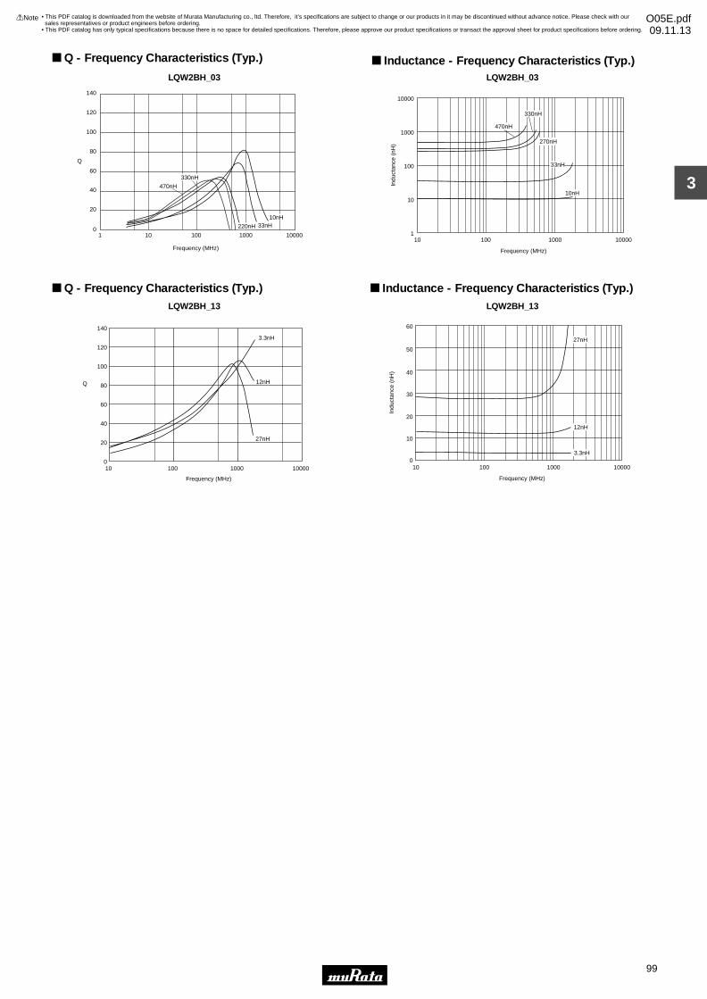
3
!Note • Please read rating and !CAUTION (for storage, operating, rating, soldering, mounting and handling) in this catalog to prevent smoking and/or burning, etc.• This catalog has only typical specifications because there is no space for detailed specifications. Therefore, please approve our product specifications or transact the approval sheet for product specifications before ordering.
99
• This PDF catalog is downloaded from the website of Murata Manufacturing co., ltd. Therefore, it’s specifications are subject to change or our products in it may be discontinued without advance notice. Please check with our sales representatives or product engineers before ordering.
• This PDF catalog has only typical specifications because there is no space for detailed specifications. Therefore, please approve our product specifications or transact the approval sheet for product specifications before ordering.
!Note O05E.pdf09.11.13
LQW2BH_03
1 10 100 10000
Frequency (MHz)
100
80
120
140
60
40
20
01000
Q
10nH33nH220nH
330nH
470nH
Q - Frequency Characteristics (Typ.)
LQW2BH_03
LQW2BH_13 LQW2BH_13
1
10
100
1000
10000
10 100 1000 10000
Frequency (MHz)
Indu
ctan
ce (
nH)
470nH
330nH
270nH
33nH
10nH
Inductance - Frequency Characteristics (Typ.)
10 1000100 100000
20
40
60
80
100
120
140
3.3nH
27nH
12nHQ
Frequency (MHz)
Q - Frequency Characteristics (Typ.)
10 100 1000 10000
Frequency (MHz)
Indu
ctan
ce (
nH)
60
50
40
30
20
10
0
27nH
3.3nH
12nH
Inductance - Frequency Characteristics (Typ.)
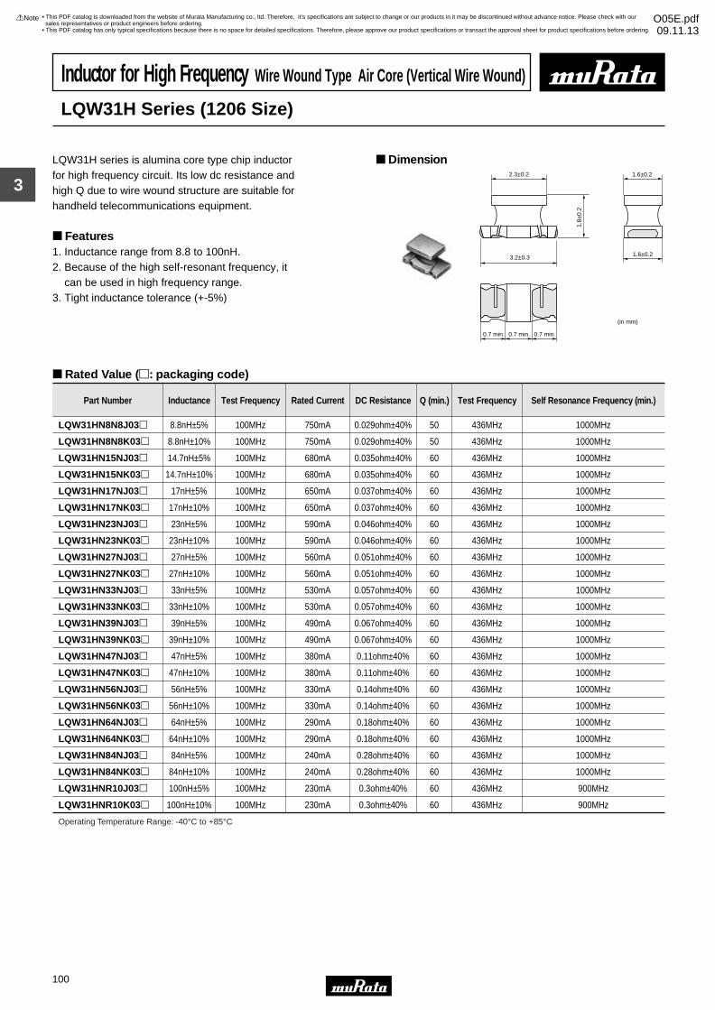
3
!Note • Please read rating and !CAUTION (for storage, operating, rating, soldering, mounting and handling) in this catalog to prevent smoking and/or burning, etc.• This catalog has only typical specifications because there is no space for detailed specifications. Therefore, please approve our product specifications or transact the approval sheet for product specifications before ordering.
100
• This PDF catalog is downloaded from the website of Murata Manufacturing co., ltd. Therefore, it’s specifications are subject to change or our products in it may be discontinued without advance notice. Please check with our sales representatives or product engineers before ordering.
• This PDF catalog has only typical specifications because there is no space for detailed specifications. Therefore, please approve our product specifications or transact the approval sheet for product specifications before ordering.
!Note O05E.pdf09.11.13
Inductor for High Frequency Wire Wound Type Air Core (Vertical Wire Wound)
LQW31H Series (1206 Size)
LQW31H series is alumina core type chip inductor for high frequency circuit. Its low dc resistance and high Q due to wire wound structure are suitable for handheld telecommunications equipment.
Features1. Inductance range from 8.8 to 100nH.2. Because of the high self-resonant frequency, it can be used in high frequency range.3. Tight inductance tolerance (+-5%)
Dimension
Rated Value (p: packaging code)
2.3±0.2
1.8±
0.2
1.6±0.2
1.6±0.23.2±0.3
0.7 min. 0.7 min. 0.7 min.
(in mm)
Part Number Inductance Test Frequency Rated Current DC Resistance Q (min.) Test Frequency Self Resonance Frequency (min.)
LQW31HN8N8J03p 8.8nH±5% 100MHz 750mA 0.029ohm±40% 50 436MHz 1000MHz
LQW31HN8N8K03p 8.8nH±10% 100MHz 750mA 0.029ohm±40% 50 436MHz 1000MHz
LQW31HN15NJ03p 14.7nH±5% 100MHz 680mA 0.035ohm±40% 60 436MHz 1000MHz
LQW31HN15NK03p 14.7nH±10% 100MHz 680mA 0.035ohm±40% 60 436MHz 1000MHz
LQW31HN17NJ03p 17nH±5% 100MHz 650mA 0.037ohm±40% 60 436MHz 1000MHz
LQW31HN17NK03p 17nH±10% 100MHz 650mA 0.037ohm±40% 60 436MHz 1000MHz
LQW31HN23NJ03p 23nH±5% 100MHz 590mA 0.046ohm±40% 60 436MHz 1000MHz
LQW31HN23NK03p 23nH±10% 100MHz 590mA 0.046ohm±40% 60 436MHz 1000MHz
LQW31HN27NJ03p 27nH±5% 100MHz 560mA 0.051ohm±40% 60 436MHz 1000MHz
LQW31HN27NK03p 27nH±10% 100MHz 560mA 0.051ohm±40% 60 436MHz 1000MHz
LQW31HN33NJ03p 33nH±5% 100MHz 530mA 0.057ohm±40% 60 436MHz 1000MHz
LQW31HN33NK03p 33nH±10% 100MHz 530mA 0.057ohm±40% 60 436MHz 1000MHz
LQW31HN39NJ03p 39nH±5% 100MHz 490mA 0.067ohm±40% 60 436MHz 1000MHz
LQW31HN39NK03p 39nH±10% 100MHz 490mA 0.067ohm±40% 60 436MHz 1000MHz
LQW31HN47NJ03p 47nH±5% 100MHz 380mA 0.11ohm±40% 60 436MHz 1000MHz
LQW31HN47NK03p 47nH±10% 100MHz 380mA 0.11ohm±40% 60 436MHz 1000MHz
LQW31HN56NJ03p 56nH±5% 100MHz 330mA 0.14ohm±40% 60 436MHz 1000MHz
LQW31HN56NK03p 56nH±10% 100MHz 330mA 0.14ohm±40% 60 436MHz 1000MHz
LQW31HN64NJ03p 64nH±5% 100MHz 290mA 0.18ohm±40% 60 436MHz 1000MHz
LQW31HN64NK03p 64nH±10% 100MHz 290mA 0.18ohm±40% 60 436MHz 1000MHz
LQW31HN84NJ03p 84nH±5% 100MHz 240mA 0.28ohm±40% 60 436MHz 1000MHz
LQW31HN84NK03p 84nH±10% 100MHz 240mA 0.28ohm±40% 60 436MHz 1000MHz
LQW31HNR10J03p 100nH±5% 100MHz 230mA 0.3ohm±40% 60 436MHz 900MHz
LQW31HNR10K03p 100nH±10% 100MHz 230mA 0.3ohm±40% 60 436MHz 900MHz
Operating Temperature Range: -40°C to +85°C
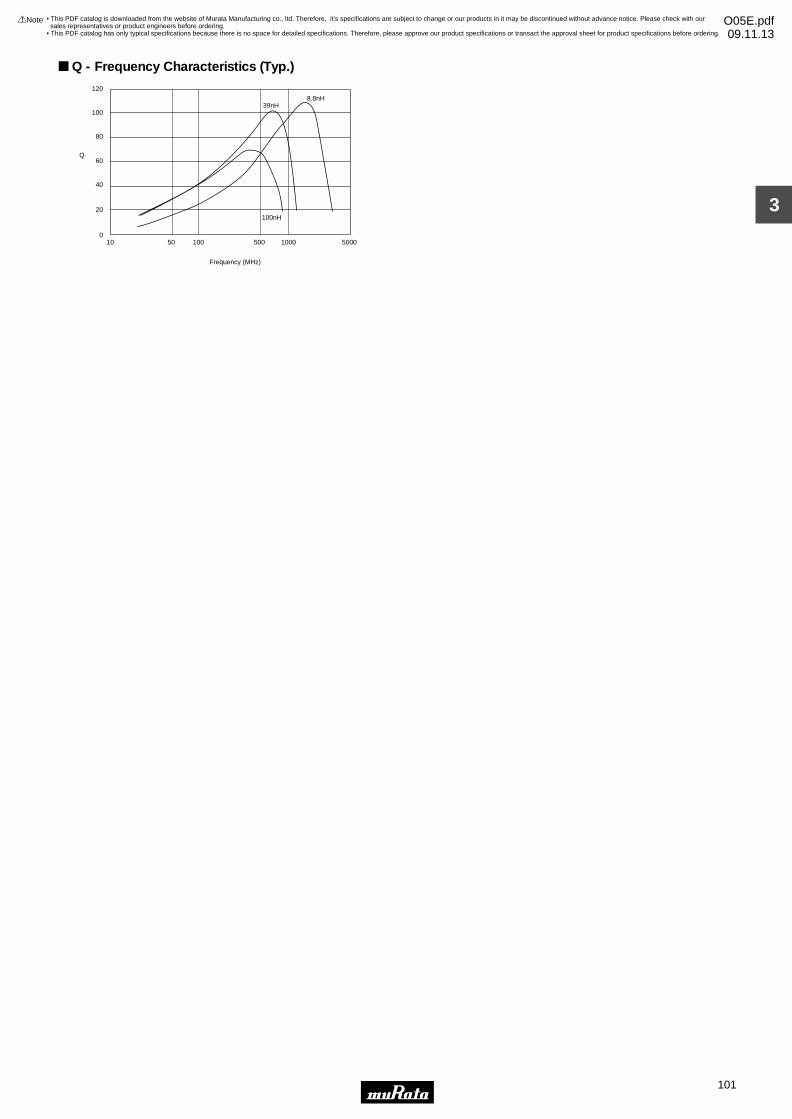
3
!Note • Please read rating and !CAUTION (for storage, operating, rating, soldering, mounting and handling) in this catalog to prevent smoking and/or burning, etc.• This catalog has only typical specifications because there is no space for detailed specifications. Therefore, please approve our product specifications or transact the approval sheet for product specifications before ordering.
101
• This PDF catalog is downloaded from the website of Murata Manufacturing co., ltd. Therefore, it’s specifications are subject to change or our products in it may be discontinued without advance notice. Please check with our sales representatives or product engineers before ordering.
• This PDF catalog has only typical specifications because there is no space for detailed specifications. Therefore, please approve our product specifications or transact the approval sheet for product specifications before ordering.
!Note O05E.pdf09.11.13
10 50 100 500 1000 5000
Frequency (MHz)
120
100
80
60
40
20
0
Q
39nH8.8nH
100nH
Q - Frequency Characteristics (Typ.)
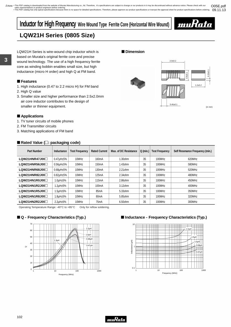
3
!Note • Please read rating and !CAUTION (for storage, operating, rating, soldering, mounting and handling) in this catalog to prevent smoking and/or burning, etc.• This catalog has only typical specifications because there is no space for detailed specifications. Therefore, please approve our product specifications or transact the approval sheet for product specifications before ordering.
102
• This PDF catalog is downloaded from the website of Murata Manufacturing co., ltd. Therefore, it’s specifications are subject to change or our products in it may be discontinued without advance notice. Please check with our sales representatives or product engineers before ordering.
• This PDF catalog has only typical specifications because there is no space for detailed specifications. Therefore, please approve our product specifications or transact the approval sheet for product specifications before ordering.
!Note O05E.pdf09.11.13
Inductor for High Frequency Wire Wound Type Ferrite Core (Horizontal Wire Wound)
LQW21H Series (0805 Size)
LQW21H Series is wire-wound chip inductor which isbased on Murata's original ferrite core and precisewound technology. The use of a high frequency ferritecore as winding bobbin enables small size, but highinductance (micro H order) and high Q at FM band.
Features1. High inductance (0.47 to 2.2 micro H) for FM band 2. High Q value3. Smaller size and higher performance than 2.5x2.0mm air core inductor contributes to the design of smaller or thinner equipment.
Applications1. TV tuner circuits of mobile phones2. FM Transmitter circuits3. Matching applications of FM band
Dimension
Rated Value (p: packaging code)
0.45±0.1
1.2±0.2
2.0±0.2
0.15
±0.1
(in mm)
0.9±
0.1
Part Number Inductance Test Frequency Rated Current Max. of DC Resistance Q (min.) Test Frequency Self Resonance Frequency (min.)
LQW21HNR47J00p 0.47µH±5% 10MHz 160mA 1.30ohm 35 100MHz 620MHz
LQW21HNR56J00p 0.56µH±5% 10MHz 150mA 1.43ohm 35 100MHz 580MHz
LQW21HNR68J00p 0.68µH±5% 10MHz 130mA 2.21ohm 35 100MHz 520MHz
LQW21HNR82J00p 0.82µH±5% 10MHz 125mA 2.34ohm 35 100MHz 480MHz
LQW21HN1R0J00p 1.0µH±5% 10MHz 115mA 2.86ohm 35 100MHz 450MHz
LQW21HN1R2J00p 1.2µH±5% 10MHz 100mA 3.12ohm 35 100MHz 400MHz
LQW21HN1R5J00p 1.5µH±5% 10MHz 85mA 5.33ohm 35 100MHz 350MHz
LQW21HN1R8J00p 1.8µH±5% 10MHz 80mA 5.85ohm 35 100MHz 320MHz
LQW21HN2R2J00p 2.2µH±5% 10MHz 75mA 6.50ohm 35 100MHz 300MHz
Operating Temperature Range: -40°C to +85°C Only for reflow soldering.
Frequency (MHz)
Q
0
10
20
30
40
50
60
70
1 10 100 1000
0.47µH
0.68µH
1.0µH
2.2µH
1.5µH
Q - Frequency Characteristics (Typ.)
Indu
ctan
ce (
µH)
Frequency (MHz)
0.11
1
10
10
1000100
2.2µH
1.5µH
1.0µH
0.68µH
0.47µH
Inductance - Frequency Characteristics (Typ.)
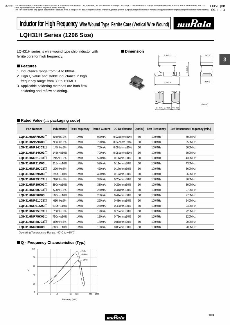
3
!Note • Please read rating and !CAUTION (for storage, operating, rating, soldering, mounting and handling) in this catalog to prevent smoking and/or burning, etc.• This catalog has only typical specifications because there is no space for detailed specifications. Therefore, please approve our product specifications or transact the approval sheet for product specifications before ordering.
103
• This PDF catalog is downloaded from the website of Murata Manufacturing co., ltd. Therefore, it’s specifications are subject to change or our products in it may be discontinued without advance notice. Please check with our sales representatives or product engineers before ordering.
• This PDF catalog has only typical specifications because there is no space for detailed specifications. Therefore, please approve our product specifications or transact the approval sheet for product specifications before ordering.
!Note O05E.pdf09.11.13
Inductor for High Frequency Wire Wound Type Ferrite Core (Vertical Wire Wound)
LQH31H Series (1206 Size)
LQH31H series is wire wound type chip inductor with ferrite core for high frequency.
Features1. Inductance range from 54 to 880nH2. High Q value and stable inductance in high frequency range from 30 to 150MHz3. Applicable soldering methods are both flow soldering and reflow soldering.
Dimension
Rated Value (p: packaging code)
2.3±0.2
1.8±
0.2
1.6±0.2
1.6±0.23.2±0.3
0.7 min. 0.7 min. 0.7 min.
(in mm)
Part Number Inductance Test Frequency Rated Current DC Resistance Q (min.) Test Frequency Self Resonance Frequency (min.)
LQH31HN54NK03p 54nH±10% 1MHz 920mA 0.035ohm±30% 50 100MHz 800MHz
LQH31HN95NK03p 95nH±10% 1MHz 790mA 0.047ohm±30% 60 100MHz 650MHz
LQH31HNR14J03p 145nH±5% 1MHz 700mA 0.061ohm±30% 60 100MHz 500MHz
LQH31HNR14K03p 145nH±10% 1MHz 700mA 0.061ohm±30% 60 100MHz 500MHz
LQH31HNR21J03p 215nH±5% 1MHz 520mA 0.11ohm±30% 60 100MHz 430MHz
LQH31HNR21K03p 215nH±10% 1MHz 520mA 0.11ohm±30% 60 100MHz 430MHz
LQH31HNR29J03p 290nH±5% 1MHz 420mA 0.17ohm±30% 60 100MHz 360MHz
LQH31HNR29K03p 290nH±10% 1MHz 420mA 0.17ohm±30% 60 100MHz 360MHz
LQH31HNR39J03p 390nH±5% 1MHz 330mA 0.26ohm±30% 60 100MHz 300MHz
LQH31HNR39K03p 390nH±10% 1MHz 330mA 0.26ohm±30% 60 100MHz 300MHz
LQH31HNR50J03p 500nH±5% 1MHz 260mA 0.44ohm±30% 60 100MHz 270MHz
LQH31HNR50K03p 500nH±10% 1MHz 260mA 0.44ohm±30% 60 100MHz 270MHz
LQH31HNR61J03p 610nH±5% 1MHz 250mA 0.48ohm±30% 60 100MHz 240MHz
LQH31HNR61K03p 610nH±10% 1MHz 250mA 0.48ohm±30% 60 100MHz 240MHz
LQH31HNR75J03p 750nH±5% 1MHz 190mA 0.79ohm±30% 60 100MHz 220MHz
LQH31HNR75K03p 750nH±10% 1MHz 190mA 0.79ohm±30% 60 100MHz 220MHz
LQH31HNR88J03p 880nH±5% 1MHz 180mA 0.86ohm±30% 60 100MHz 200MHz
LQH31HNR88K03p 880nH±10% 1MHz 180mA 0.86ohm±30% 60 100MHz 200MHz
Operating Temperature Range: -40°C to +85°C
215nH
880nH
54nH
1 5 10 50 100 500 1000
Frequency (MHz)
100
80
60
40
20
0
Q
Q - Frequency Characteristics (Typ.)
!Caution (Rating)Do not use products beyond the rated current asthis may create excessive heat.
Notice (Storage and Operating Condition)<Operating Environment>Do not use products in chemical atmosphere such as chlorine gas, acid or sulfide gas.<Storage Requirements>1. Storage Period LQG/LQM series should be used within 6 months; the other products should be used within 12 months. Check solderability if this period is exceeded.2. Storage Conditions (1) Store products in a warehouse in compliance with the following conditions: Temperature: -10 to +40 degrees C. Humidity: 15 to 85% (relative humidity)
Do not subject products to rapid changes in temperature and humidity. Do not store them in chemical atmosphere such as one containing sulfurous acid gas or alkaline gas. This will prevent electrode oxidation which causes poor solderability and possible corrosion of inductors. (2) Do not store products in bulk packaging to prevent collision among inductors which causes core chipping and wire breakage. (3) Store products on pallets to protect from humidity, dust, etc. (4) Avoid heat shock, vibration, direct sunlight, etc.
Notice (Handling)This item is designed to have sufficient strength, but handle with care to avoid chipping or breaking its ceramic structure.LQW_A series/ LQW_H series• To prevent breaking the wire, avoid touching sharp material, such as tweezers, to the wire wound portion.• To prevent breaking the core, avoid applying excessive mechanical shock to products mounted on the board.• In some mounting machines, when picking up components, support pin pushes up the components from the bottom of base tape. In this case, please remove the support pin. The support pin may damage the components and break wire.• In rare case, the laser recognition can not recognize this component. Please contact us when you use laser recognizion. (There is no problem with the permeation and reflection type.)LQH_C/D/H/M/N/P series• To prevent breaking the wire, avoid touching sharp material, such as tweezers, to the wire wound portion.• To prevent breaking the core, avoid applying excessive mechanical shock to products mounted on the board.
• Temperature may rise up to max. 40 °C when applying the rated current to LQH3NP. Be careful of the temperature rating of the circuit board and components around the chip inductor.LQG,LQP series (exept LQP02T_02/LQP03T_02)• The pattern of the chip inductor is covered with protective film. Take care to avoid damaging the chip inductor when handling it with pick-up nozzles, sharp instruments, etc.LQM series• There is the possibility that magnetism may change the inductance value. Do not use a magnet or tweezers with magnetism when handling chip inductors. (The tip of the tweezers should be molded with resin or pottery.)• When the excessive current over rated current is applied, it may cause the inductance value to change due to magnetism.<Handling>1. Avoid applying excessive stress to products to prevent damage.2. Do not touch wire wound with sharp objects such as tweezers to prevent wire breakage.3. Do not apply excessive force to products mounted on boards to prevent core breakage.
!Caution/Notice
Continued on the following page.
!Caution/Notice
!Note • Please read rating and !CAUTION (for storage, operating, rating, soldering, mounting and handling) in this catalog to prevent smoking and/or burning, etc.• This catalog has only typical specifications because there is no space for detailed specifications. Therefore, please approve our product specifications or transact the approval sheet for product specifications before ordering.
104
• This PDF catalog is downloaded from the website of Murata Manufacturing co., ltd. Therefore, it’s specifications are subject to change or our products in it may be discontinued without advance notice. Please check with our sales representatives or product engineers before ordering.
• This PDF catalog has only typical specifications because there is no space for detailed specifications. Therefore, please approve our product specifications or transact the approval sheet for product specifications before ordering.
!Note O05E.pdf09.11.13
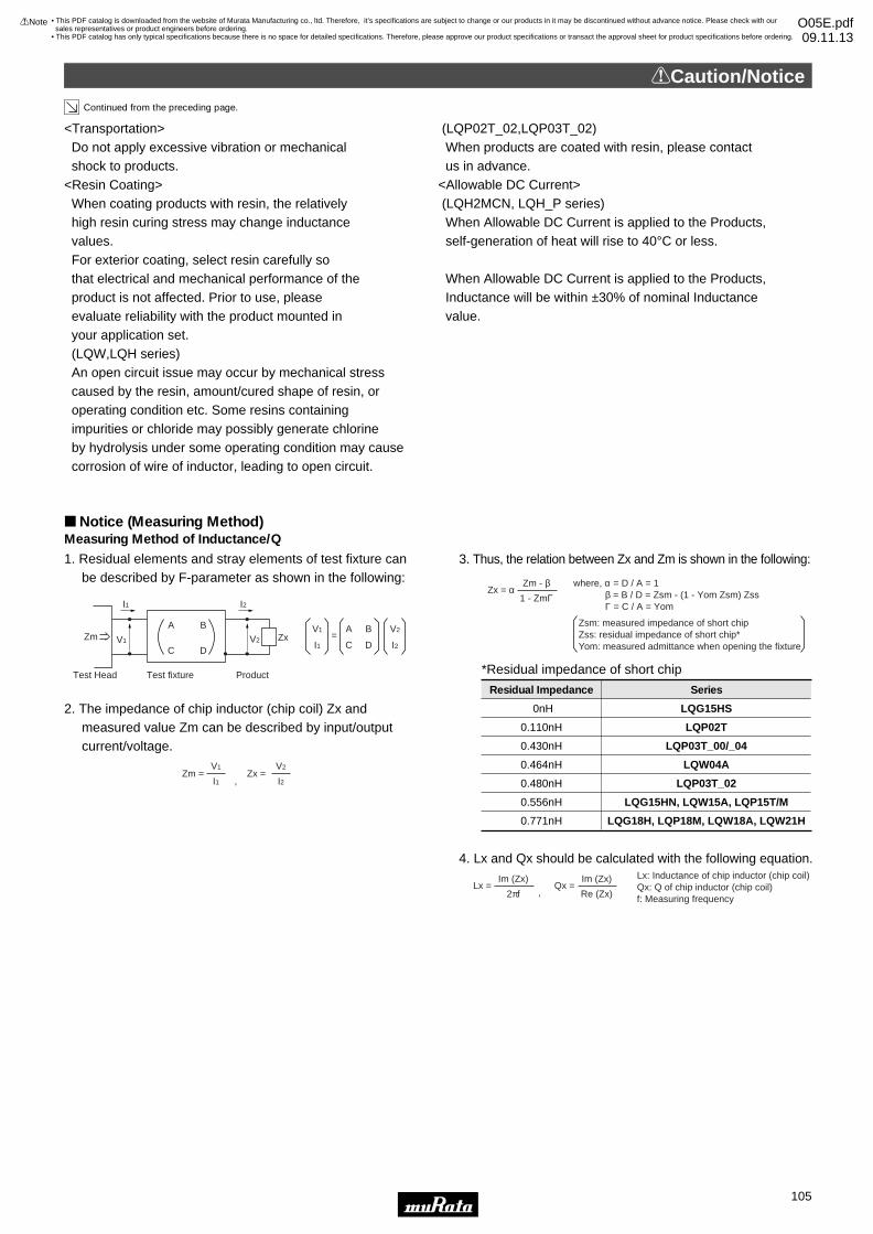
Notice (Measuring Method)
<Transportation> Do not apply excessive vibration or mechanical shock to products.<Resin Coating> When coating products with resin, the relatively high resin curing stress may change inductance values. For exterior coating, select resin carefully so that electrical and mechanical performance of the product is not affected. Prior to use, please evaluate reliability with the product mounted in your application set. (LQW,LQH series) An open circuit issue may occur by mechanical stress caused by the resin, amount/cured shape of resin, or operating condition etc. Some resins containing impurities or chloride may possibly generate chlorine by hydrolysis under some operating condition may cause corrosion of wire of inductor, leading to open circuit.
(LQP02T_02,LQP03T_02) When products are coated with resin, please contact us in advance.<Allowable DC Current> (LQH2MCN, LQH_P series) When Allowable DC Current is applied to the Products, self-generation of heat will rise to 40°C or less. When Allowable DC Current is applied to the Products, Inductance will be within ±30% of nominal Inductance value.
!Caution/Notice
Measuring Method of Inductance/Q
1. Residual elements and stray elements of test fixture can be described by F-parameter as shown in the following:
2. The impedance of chip inductor (chip coil) Zx and measured value Zm can be described by input/output current/voltage.
3. Thus, the relation between Zx and Zm is shown in the following:
4. Lx and Qx should be calculated with the following equation.
0nH LQG15HS
0.430nH LQP03T_00/_04
0.110nH LQP02T
0.464nH LQW04A
0.480nH LQP03T_02
0.556nH LQG15HN, LQW15A, LQP15T/M
0.771nH LQG18H, LQP18M, LQW18A, LQW21H
Residual Impedance Series
V1 A=
B
I1 C D
V2
I2
A B
C D
Zm ZxV1 V2
I1 I2
ProductTest fixtureTest Head
V1
I1 ,Zm =
Zm - β1 - ZmΓ
Zx = α
V2
I2Zx =
where, α = D / A = 1 β = B / D = Zsm - (1 - Yom Zsm) Zss Γ = C / A = Yom
Zsm: measured impedance of short chipZss: residual impedance of short chip*Yom: measured admittance when opening the fixture
Lx: Inductance of chip inductor (chip coil)Qx: Q of chip inductor (chip coil)f: Measuring frequency
*Residual impedance of short chip
,
Im (Zx)
2πfLx =
Im (Zx)
Re (Zx)Qx =
Continued from the preceding page.
!Caution/Notice
!Note • Please read rating and !CAUTION (for storage, operating, rating, soldering, mounting and handling) in this catalog to prevent smoking and/or burning, etc.• This catalog has only typical specifications because there is no space for detailed specifications. Therefore, please approve our product specifications or transact the approval sheet for product specifications before ordering.
105
• This PDF catalog is downloaded from the website of Murata Manufacturing co., ltd. Therefore, it’s specifications are subject to change or our products in it may be discontinued without advance notice. Please check with our sales representatives or product engineers before ordering.
• This PDF catalog has only typical specifications because there is no space for detailed specifications. Therefore, please approve our product specifications or transact the approval sheet for product specifications before ordering.
!Note O05E.pdf09.11.13
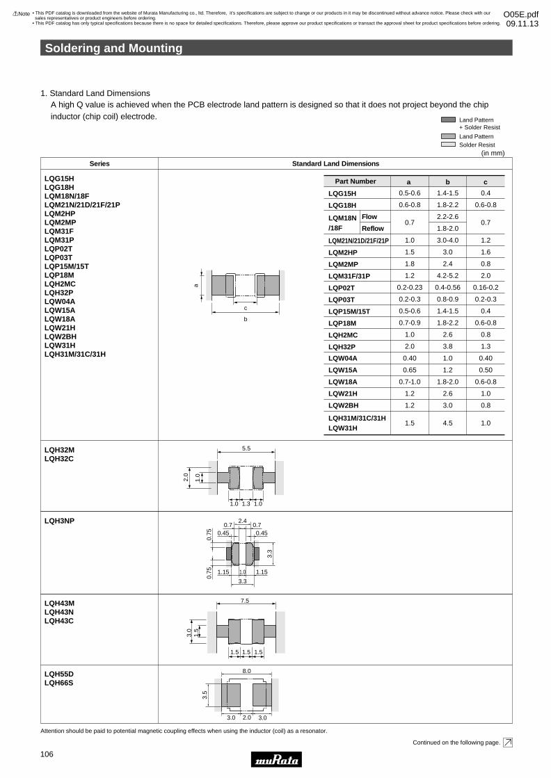
A high Q value is achieved when the PCB electrode land pattern is designed so that it does not project beyond the chip inductor (chip coil) electrode.
(in mm)
c
a
b
Standard Land DimensionsSeries
LQW04A
LQW15A
LQW18A
LQW21H
LQW2BH
LQH31M/31C/31HLQW31H
0.40
0.65
0.7-1.0
1.2
1.2
1.5
1.0
1.2
1.8-2.0
2.6
3.0
4.5
0.40
0.50
0.6-0.8
1.0
0.8
1.0
LQG15H
LQG18H
LQM18N/18F
LQM21N/21D/21F/21P
LQM2HP
LQM2MP
LQM31F/31P
LQP02T
LQP03T
LQP15M/15T
LQP18M
LQH2MC
LQH32P
0.5-0.6
0.6-0.8
0.7
1.0
1.5
1.8
1.2
0.2-0.23
0.2-0.3
0.5-0.6
0.7-0.9
1.0
2.0
1.4-1.5
1.8-2.2
2.2-2.6
1.8-2.0
3.0-4.0
3.0
2.4
4.2-5.2
0.4-0.56
0.8-0.9
1.4-1.5
1.8-2.2
2.6
3.8
0.4
0.6-0.8
0.7
1.2
1.6
0.8
2.0
0.16-0.2
0.2-0.3
0.4
0.6-0.8
0.8
1.3
7.5
1.5
3.0
1.5
1.5 1.5
8.0
3.5
3.0 2.0 3.0
LQG15HLQG18HLQM18N/18FLQM21N/21D/21F/21PLQM2HPLQM2MPLQM31FLQM31PLQP02TLQP03TLQP15M/15TLQP18MLQH2MCLQH32PLQW04ALQW15ALQW18ALQW21HLQW2BHLQW31HLQH31M/31C/31H
LQH32MLQH32C
LQH43MLQH43NLQH43C
LQH55DLQH66S
Part Number a b c
1. Standard Land Dimensions
Attention should be paid to potential magnetic coupling effects when using the inductor (coil) as a resonator.
Land Pattern
Land Pattern+ Solder Resist
Solder Resist
5.5
1.0
2.0
1.0
1.3 1.0
2.4
0.75
0.75
3.3
1.01.15 1.15
0.45 0.450.7 0.7
3.3
Flow
Reflow
Continued on the following page.
LQH3NP
Soldering and Mounting
!Note • Please read rating and !CAUTION (for storage, operating, rating, soldering, mounting and handling) in this catalog to prevent smoking and/or burning, etc.• This catalog has only typical specifications because there is no space for detailed specifications. Therefore, please approve our product specifications or transact the approval sheet for product specifications before ordering.
106
• This PDF catalog is downloaded from the website of Murata Manufacturing co., ltd. Therefore, it’s specifications are subject to change or our products in it may be discontinued without advance notice. Please check with our sales representatives or product engineers before ordering.
• This PDF catalog has only typical specifications because there is no space for detailed specifications. Therefore, please approve our product specifications or transact the approval sheet for product specifications before ordering.
!Note O05E.pdf09.11.13
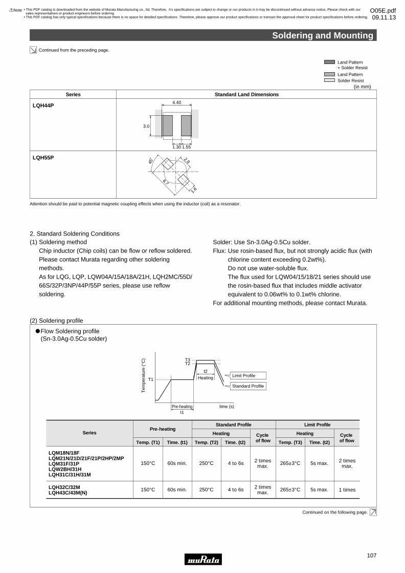
Continued from the preceding page.
2. Standard Soldering Conditions(1) Soldering method
Chip inductor (Chip coils) can be flow or reflow soldered. Please contact Murata regarding other soldering methods.As for LQG, LQP, LQW04A/15A/18A/21H, LQH2MC/55D/ 66S/32P/3NP/44P/55P series, please use reflow soldering.
Solder: Use Sn-3.0Ag-0.5Cu solder.Flux: Use rosin-based flux, but not strongly acidic flux (with
chlorine content exceeding 0.2wt%).Do not use water-soluble flux.The flux used for LQW04/15/18/21 series should use the rosin-based flux that includes middle activator equivalent to 0.06wt% to 0.1wt% chlorine.
For additional mounting methods, please contact Murata.
(2) Soldering profile
Continued on the following page.
"Flow Soldering profile (Sn-3.0Ag-0.5Cu solder)
SeriesPre-heating
Standard Profile Limit Profile
Heating
Temp. (T1) Temp. (T2)Time. (t1)
150°C 60s min. 250°C 4 to 6s 2 timesmax. 5s max. 2 times
max.265±3°C
Time. (t2)
HeatingCycle of flow Temp. (T3) Time. (t2)
Cycle of flow
T1
T3T2
Tem
pera
ture
(°C
)
Pre-heating time (s)
t2
Heating Limit Profile
Standard Profile
t1
150°C 60s min. 250°C 4 to 6s 2 timesmax. 5s max. 1 times265±3°C
LQM18N/18FLQM21N/21D/21F/21P/2HP/2MPLQM31F/31PLQW2BH/31HLQH31C/31H/31M
LQH32C/32MLQH43C/43M(N)
LQH44P
LQH55P 2.9
6.7
1.6
45˚
Attention should be paid to potential magnetic coupling effects when using the inductor (coil) as a resonator.
Standard Land DimensionsSeries
(in mm)
Land Pattern
Land Pattern+ Solder Resist
Solder Resist
1.30 1.55
4.40
3.0
Soldering and Mounting
!Note • Please read rating and !CAUTION (for storage, operating, rating, soldering, mounting and handling) in this catalog to prevent smoking and/or burning, etc.• This catalog has only typical specifications because there is no space for detailed specifications. Therefore, please approve our product specifications or transact the approval sheet for product specifications before ordering.
107
• This PDF catalog is downloaded from the website of Murata Manufacturing co., ltd. Therefore, it’s specifications are subject to change or our products in it may be discontinued without advance notice. Please check with our sales representatives or product engineers before ordering.
• This PDF catalog has only typical specifications because there is no space for detailed specifications. Therefore, please approve our product specifications or transact the approval sheet for product specifications before ordering.
!Note O05E.pdf09.11.13
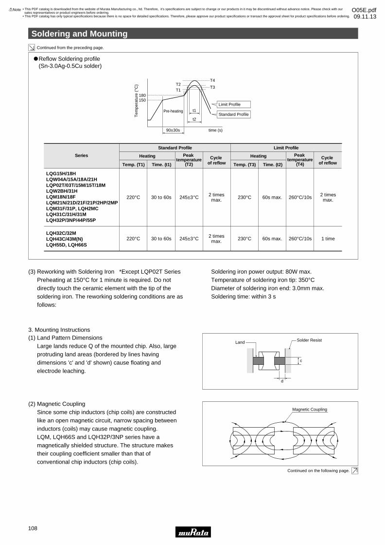
Continued from the preceding page.
Continued on the following page.
"Reflow Soldering profile (Sn-3.0Ag-0.5Cu solder)
Series
Standard Profile Limit Profile
Temp. (T1) Time. (t1)
Heating
220°C 30 to 60s 245±3°C 2 timesmax. 230°C 260°C/10s 2 times
max.60s max.
Cycle of reflow
Peak temperature
(T2) Temp. (T3) Time. (t2)
Heating Cycle of reflow
Peak temperature
(T4)
150180
T2T4
T3T1
Tem
pera
ture
(°C
)90±30s time (s)
t2
t1Limit Profile
Standard ProfilePre-heating
LQG15H/18HLQW04A/15A/18A/21HLQP02T/03T/15M/15T/18MLQW2BH/31HLQM18N/18FLQM21N/21D/21F/21P/2HP/2MPLQM31F/31P, LQH2MCLQH31C/31H/31MLQH32P/3NP/44P/55P
LQH32C/32MLQH43C/43M(N)LQH55D, LQH66S
220°C 30 to 60s 245±3°C 2 timesmax. 230°C 260°C/10s 1 time60s max.
(3) Reworking with Soldering Iron *Except LQP02T SeriesPreheating at 150°C for 1 minute is required. Do not directly touch the ceramic element with the tip of the soldering iron. The reworking soldering conditions are as follows:
Soldering iron power output: 80W max.Temperature of soldering iron tip: 350°CDiameter of soldering iron end: 3.0mm max.Soldering time: within 3 s
3. Mounting Instructions(1) Land Pattern Dimensions
Large lands reduce Q of the mounted chip. Also, large protruding land areas (bordered by lines having dimensions 'c' and 'd' shown) cause floating and electrode leaching.
(2) Magnetic CouplingSince some chip inductors (chip coils) are constructed like an open magnetic circuit, narrow spacing between inductors (coils) may cause magnetic coupling.LQM, LQH66S and LQH32P/3NP series have a magnetically shielded structure. The structure makes their coupling coefficient smaller than that of conventional chip inductors (chip coils).
d
c
Magnetic Coupling
Land Solder Resist
Soldering and Mounting
!Note • Please read rating and !CAUTION (for storage, operating, rating, soldering, mounting and handling) in this catalog to prevent smoking and/or burning, etc.• This catalog has only typical specifications because there is no space for detailed specifications. Therefore, please approve our product specifications or transact the approval sheet for product specifications before ordering.
108
• This PDF catalog is downloaded from the website of Murata Manufacturing co., ltd. Therefore, it’s specifications are subject to change or our products in it may be discontinued without advance notice. Please check with our sales representatives or product engineers before ordering.
• This PDF catalog has only typical specifications because there is no space for detailed specifications. Therefore, please approve our product specifications or transact the approval sheet for product specifications before ordering.
!Note O05E.pdf09.11.13
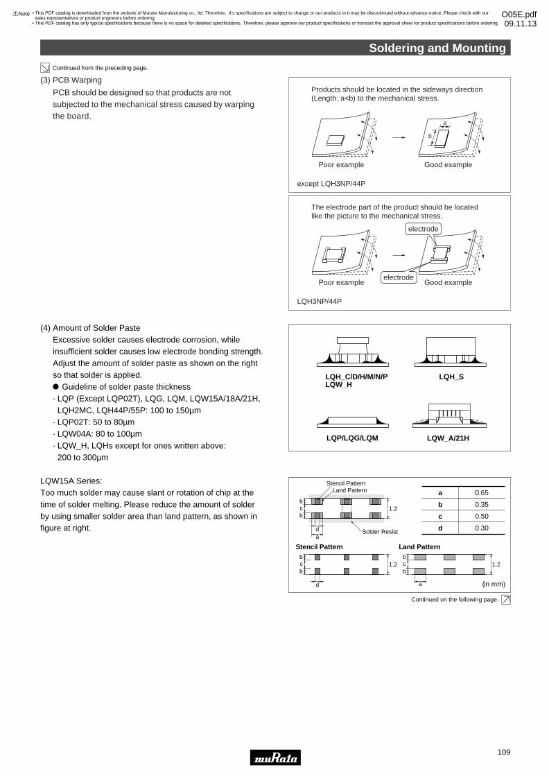
Continued from the preceding page.
(3) PCB Warping
PCB should be designed so that products are not subjected to the mechanical stress caused by warping the board.
Poor example
except LQH3NP/44P
Products should be located in the sideways direction (Length: a<b) to the mechanical stress.
Good example
a
b
Poor example
LQH3NP/44P
The electrode part of the product should be located like the picture to the mechanical stress.
Good example
Continued on the following page.
LQP/LQG/LQM
LQH_C/D/H/M/N/PLQW_H
LQH_S
LQW_A/21H
(4) Amount of Solder PasteExcessive solder causes electrode corrosion, while insufficient solder causes low electrode bonding strength. Adjust the amount of solder paste as shown on the right so that solder is applied." Guideline of solder paste thickness· LQP (Except LQP02T), LQG, LQM, LQW15A/18A/21H, LQH2MC, LQH44P/55P: 100 to 150µm· LQP02T: 50 to 80µm· LQW04A: 80 to 100µm· LQW_H, LQHs except for ones written above: 200 to 300µm
LQW15A Series:Too much solder may cause slant or rotation of chip at the time of solder melting. Please reduce the amount of solder by using smaller solder area than land pattern, as shown in figure at right.
a 0.65
(in mm)
b 0.35
c 0.50
d 0.30
1.2
Stencil PatternLand Pattern
Solder Resista
b
bc
d
1.2
Stencil Patternb
bc
d
1.2
Land Pattern
a
b
bc
electrode
electrode
Soldering and Mounting
!Note • Please read rating and !CAUTION (for storage, operating, rating, soldering, mounting and handling) in this catalog to prevent smoking and/or burning, etc.• This catalog has only typical specifications because there is no space for detailed specifications. Therefore, please approve our product specifications or transact the approval sheet for product specifications before ordering.
109
• This PDF catalog is downloaded from the website of Murata Manufacturing co., ltd. Therefore, it’s specifications are subject to change or our products in it may be discontinued without advance notice. Please check with our sales representatives or product engineers before ordering.
• This PDF catalog has only typical specifications because there is no space for detailed specifications. Therefore, please approve our product specifications or transact the approval sheet for product specifications before ordering.
!Note O05E.pdf09.11.13
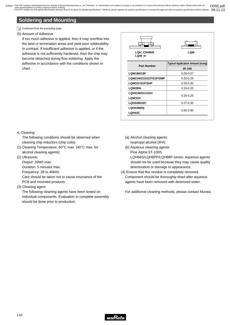
LQH_C/H/M/NLQW_H
LQM
LQM18N/18F
LQM21N/21D/21F/21P/2MP
LQM31F/31P/2HP
LQW2BH
LQH31M/31C/31H
LQW31H
LQH32M/32C
LQH43M(N)
LQH43C
0.06-0.07
0.20-0.25
0.25-0.30
0.15-0.20
0.20-0.25
0.27-0.35
0.60-0.80
Continued from the preceding page.
(5) Amount of AdhesiveIf too much adhesive is applied, then it may overflow into the land or termination areas and yield poor solderability. In contrast, if insufficient adhesive is applied, or if the adhesive is not sufficiently hardened, then the chip may become detached during flow soldering. Apply the adhesive in accordance with the conditions shown in chart.
Typical Application Amount (in:mg)Part Number
IR-100
4. CleaningThe following conditions should be observed when cleaning chip inductors (chip coils):
(1) Cleaning Temperature: 60°C max. (40°C max. for alcohol cleaning agents)
(2) Ultrasonic Output: 20W/l max.Duration: 5 minutes max.Frequency: 28 to 40kHzCare should be taken not to cause resonance of thePCB and mounted products.
(3) Cleaning agent The following cleaning agents have been tested on individual components. Evaluation in complete assembly should be done prior to production.
(a) Alcohol cleaning agentsIsopropyl alcohol (IPA)
(b) Aqueous cleaning agentsPine Alpha ST-100SLQH66S/LQH6PP/LQH88P series: Aqueous agents should not be used because they may cause quality deterioration or damage to appearance.
(4) Ensure that flux residue is completely removed.Component should be thoroughly dried after aqueous agents have been removed with deionized water.
For additional cleaning methods, please contact Murata.
Soldering and Mounting
!Note • Please read rating and !CAUTION (for storage, operating, rating, soldering, mounting and handling) in this catalog to prevent smoking and/or burning, etc.• This catalog has only typical specifications because there is no space for detailed specifications. Therefore, please approve our product specifications or transact the approval sheet for product specifications before ordering.
110
• This PDF catalog is downloaded from the website of Murata Manufacturing co., ltd. Therefore, it’s specifications are subject to change or our products in it may be discontinued without advance notice. Please check with our sales representatives or product engineers before ordering.
• This PDF catalog has only typical specifications because there is no space for detailed specifications. Therefore, please approve our product specifications or transact the approval sheet for product specifications before ordering.
!Note O05E.pdf09.11.13
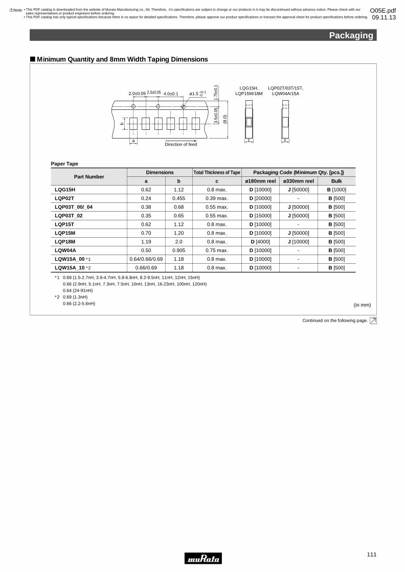
Minimum Quantity and 8mm Width Taping Dimensions
Direction of feed
2.0±0.05 4.0±0.1
a
b
c
1.75
±0.1
ø1.5 +0.1-0
3.5±
0.05
(8.0
)
2.0±0.05
c
LQG15H,LQP15M/18M
LQP02T/03T/15T,LQW04A/15A
Continued on the following page.
Part Numbera
Paper Tape
LQG15H
LQP03T_00/_04
LQP15T
LQP15M
LQP18M
LQW04A
LQW15A_00 ∗1
LQW15A_10 ∗2
0.62
0.38
0.62
0.70
1.19
0.50
0.64/0.66/0.69
0.66/0.69
b
1.12
0.68
1.12
1.20
2.0
0.905
1.18
1.18
c
0.8 max.
0.55 max.
0.8 max.
0.8 max.
0.8 max.
0.75 max.
0.8 max.
0.8 max.
ø180mm reel
D [10000]
ø330mm reel
Dimensions Total Thickness of Tape Packaging Code (Minimum Qty. [pcs.])
J [50000]
Bulk
B [1000]
D [10000] J [50000] B [500]
D [10000] - B [500]
D [10000] J [50000] B [500]
D [4000] J [10000] B [500]
D [10000] - B [500]
D [10000] - B [500]
D [10000] - B [500]
LQP03T_02 0.35 0.65 0.55 max. D [15000] J [50000] B [500]
LQP02T 0.24 0.455 0.39 max. D [20000] - B [500]
(in mm)
∗1 0.69 (1.5-2.7nH, 3.9-4.7nH, 5.8-6.8nH, 8.2-9.5nH, 11nH, 12nH, 15nH)
0.66 (2.9nH, 5.1nH, 7.3nH, 7.5nH, 10nH, 13nH, 16-23nH, 100nH, 120nH)
0.64 (24-91nH)
∗2 0.69 (1.3nH)
0.66 (2.2-5.6nH)
Packaging
!Note • Please read rating and !CAUTION (for storage, operating, rating, soldering, mounting and handling) in this catalog to prevent smoking and/or burning, etc.• This catalog has only typical specifications because there is no space for detailed specifications. Therefore, please approve our product specifications or transact the approval sheet for product specifications before ordering.
111
• This PDF catalog is downloaded from the website of Murata Manufacturing co., ltd. Therefore, it’s specifications are subject to change or our products in it may be discontinued without advance notice. Please check with our sales representatives or product engineers before ordering.
• This PDF catalog has only typical specifications because there is no space for detailed specifications. Therefore, please approve our product specifications or transact the approval sheet for product specifications before ordering.
!Note O05E.pdf09.11.13
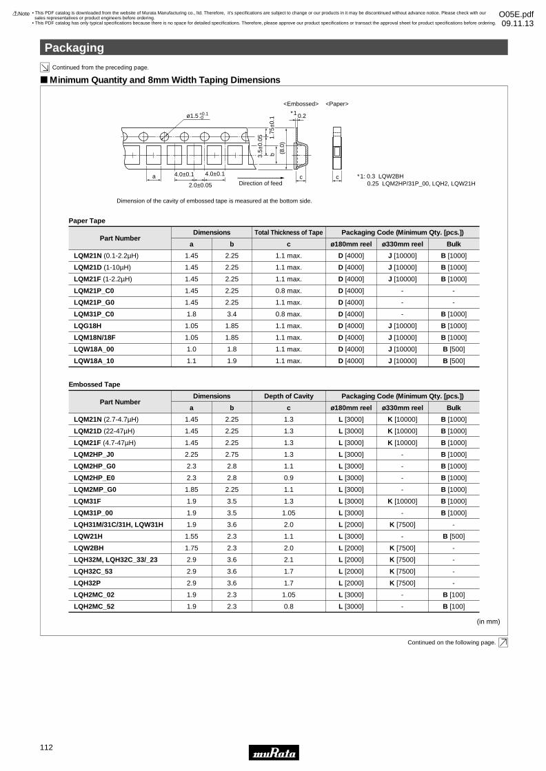
a
b
cDirection of feed
Dimension of the cavity of embossed tape is measured at the bottom side.
4.0±0.1 4.0±0.1
2.0±0.05
0.2
3.5±
0.05 1.
75±0
.1
(8.
0)
ø1.5 +0.1-0
∗1
∗1: 0.3 LQW2BH 0.25 LQM2HP/31P_00, LQH2, LQW21H
Minimum Quantity and 8mm Width Taping Dimensions
<Embossed> <Paper>
c
Continued on the following page.
(in mm)
Continued from the preceding page.
Part Numbera
Paper Tape
LQM21N (0.1-2.2µH)
LQM21D (1-10µH)
LQM21F (1-2.2µH)
LQG18H
LQM18N/18F
LQW18A_00
LQW18A_10
1.45
1.45
1.45
1.05
1.05
1.0
1.1
b
2.25
2.25
2.25
1.85
1.85
1.8
1.9
c
1.1 max.
1.1 max.
1.1 max.
1.1 max.
1.1 max.
1.1 max.
1.1 max.
ø180mm reel
D [4000]
ø330mm reel
Dimensions Packaging Code (Minimum Qty. [pcs.])
J [10000]
Bulk
B [1000]
D [4000] J [10000] B [1000]
D [4000] J [10000] B [1000]
D [4000] J [10000] B [1000]
D [4000] J [10000] B [1000]
D [4000] J [10000] B [500]
D [4000] J [10000] B [500]
LQM21P_C0 1.45 2.25 0.8 max. D [4000] - -
LQM21P_G0 1.45 2.25 1.1 max. D [4000] - -
LQM31P_C0 1.8 3.4 0.8 max. D [4000] - B [1000]
Part Numbera
Embossed Tape
LQM21N (2.7-4.7µH)
LQM21D (22-47µH)
LQM21F (4.7-47µH)
LQM31F
LQH31M/31C/31H, LQW31H
LQH32M, LQH32C_33/_23
LQH32C_53
1.45
1.45
1.45
1.9
1.9
2.9
2.9
b
2.25
2.25
2.25
3.5
3.6
3.6
3.6
c
1.3
1.3
1.3
1.3
2.0
2.1
1.7
ø180mm reel
L [3000]
ø330mm reel
Dimensions
Total Thickness of Tape
Depth of Cavity Packaging Code (Minimum Qty. [pcs.])
K [10000]
Bulk
B [1000]
L [3000] K [10000] B [1000]
L [3000] K [10000] B [1000]
LQM2HP_G0 2.3 2.8 1.1 L [3000] - B [1000]
L [3000] K [10000] B [1000]
L [2000] K [7500] -
LQW2BH 1.75 2.3 2.0 L [2000] K [7500] -
L [2000] K [7500] -
L [2000] K [7500] -
LQH32P 2.9 3.6 1.7 L [2000] K [7500] -
LQM2HP_E0 2.3 2.8 0.9 L [3000] - B [1000]
LQM2HP_J0 2.25 2.75 1.3 L [3000] - B [1000]
LQM31P_00 1.9 3.5 1.05 L [3000] - B [1000]
LQW21H 1.55 2.3 1.1 L [3000] - B [500]
LQH2MC_02 1.9 2.3 1.05 L [3000] - B [100]
LQH2MC_52 1.9 2.3 0.8 L [3000] - B [100]
LQM2MP_G0 1.85 2.25 1.1 L [3000] - B [1000]
Packaging
!Note • Please read rating and !CAUTION (for storage, operating, rating, soldering, mounting and handling) in this catalog to prevent smoking and/or burning, etc.• This catalog has only typical specifications because there is no space for detailed specifications. Therefore, please approve our product specifications or transact the approval sheet for product specifications before ordering.
112
• This PDF catalog is downloaded from the website of Murata Manufacturing co., ltd. Therefore, it’s specifications are subject to change or our products in it may be discontinued without advance notice. Please check with our sales representatives or product engineers before ordering.
• This PDF catalog has only typical specifications because there is no space for detailed specifications. Therefore, please approve our product specifications or transact the approval sheet for product specifications before ordering.
!Note O05E.pdf09.11.13
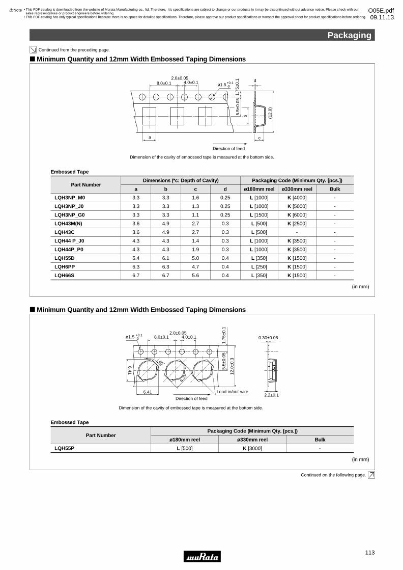
Continued from the preceding page.
(in mm)
a
b
c
d8.0±0.1
2.0±0.054.0±0.1
5.5±
0.05
1.75
±0.1
(12.
0)
ø1.5+0.1-0
Direction of feed
Minimum Quantity and 12mm Width Embossed Taping Dimensions
(in mm)
Minimum Quantity and 12mm Width Embossed Taping Dimensions
ø1.5 +0.1-0
45˚
8.0±0.12.0±0.05
4.0±0.1
5.5±
0.05
12.0
±0.3
1.75
±0.1
0.30±0.05
2.2±0.1
6.27
6.41
6.41
Direction of feed
Lead-in/out wire
Embossed Tape
Part Numberø180mm reel
Packaging Code (Minimum Qty. [pcs.])
ø330mm reel Bulk
LQH55P L [500] K [3000] -
Continued on the following page.
Dimension of the cavity of embossed tape is measured at the bottom side.
Dimension of the cavity of embossed tape is measured at the bottom side.
Part Numbera
Embossed Tape
LQH43M(N)
LQH43C
LQH55D
LQH66S
3.6
3.6
5.4
6.7
b
4.9
4.9
6.1
6.7
c
2.7
2.7
5.0
5.6
d ø180mm reel
Dimensions (*c: Depth of Cavity) Packaging Code (Minimum Qty. [pcs.])
ø330mm reel
0.3 L [500] K [2500]
0.3 L [500] -
0.4 L [350] K [1500]
0.4 L [350] K [1500]
Bulk
-
-
-
-
LQH3NP_G0 3.3 3.3 1.1 0.25 L [1500] K [6000] -
LQH3NP_J0 3.3 3.3 1.3 0.25 L [1000] K [5000] -
LQH3NP_M0 3.3 3.3 1.6 0.25 L [1000] K [4000] -
LQH44 P_J0 4.3 4.3 1.4 0.3 L [1000] K [3500] -
LQH44P_P0 4.3 4.3 1.9 0.3 L [1000] K [3500] -
LQH6PP 6.3 6.3 4.7 0.4 L [250] K [1500] -
Packaging
!Note • Please read rating and !CAUTION (for storage, operating, rating, soldering, mounting and handling) in this catalog to prevent smoking and/or burning, etc.• This catalog has only typical specifications because there is no space for detailed specifications. Therefore, please approve our product specifications or transact the approval sheet for product specifications before ordering.
113
• This PDF catalog is downloaded from the website of Murata Manufacturing co., ltd. Therefore, it’s specifications are subject to change or our products in it may be discontinued without advance notice. Please check with our sales representatives or product engineers before ordering.
• This PDF catalog has only typical specifications because there is no space for detailed specifications. Therefore, please approve our product specifications or transact the approval sheet for product specifications before ordering.
!Note O05E.pdf09.11.13
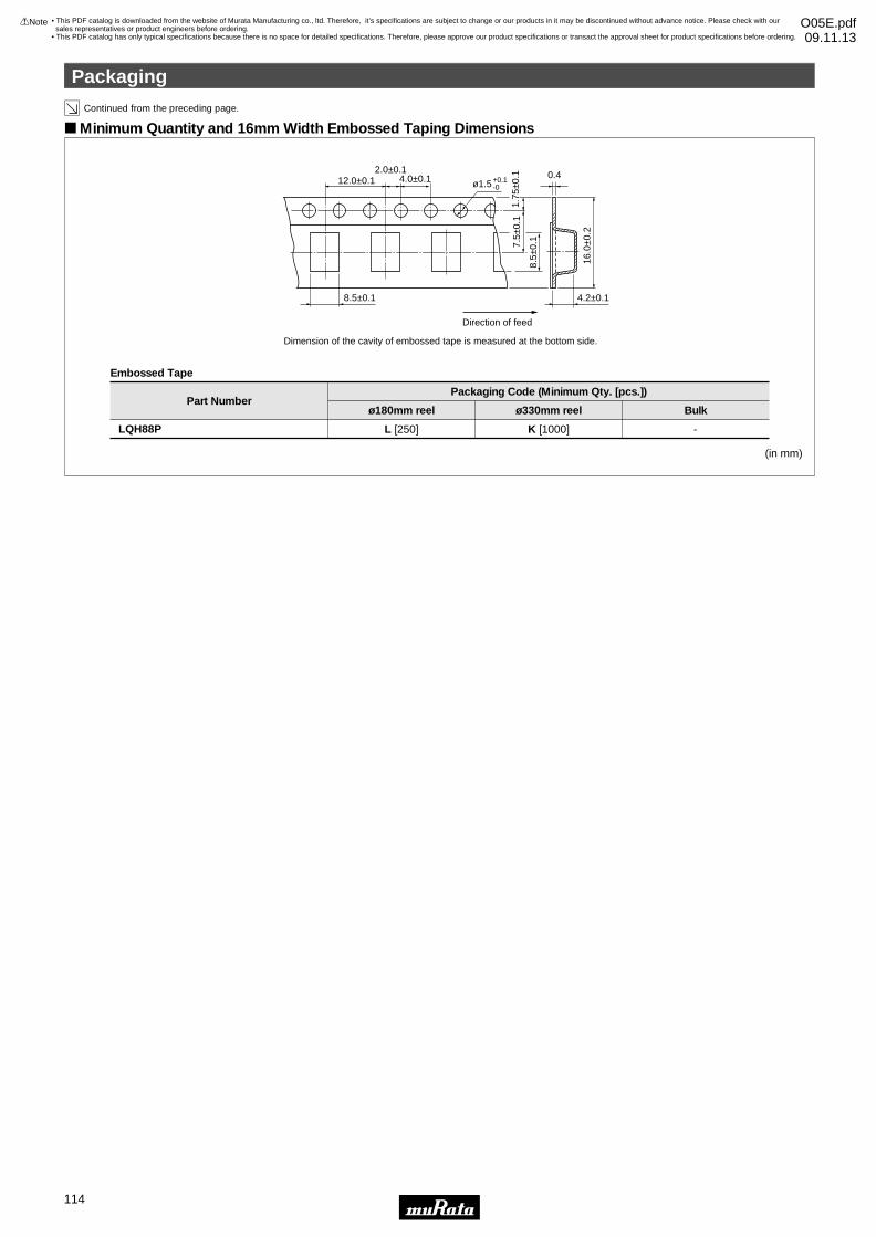
Continued from the preceding page.
8.5±0.1
8.5±
0.1
4.2±0.1
0.412.0±0.1
2.0±0.14.0±0.1
7.5±
0.1
1.75
±0.1
16.0
±0.2
ø1.5+0.1-0
Direction of feed
Minimum Quantity and 16mm Width Embossed Taping Dimensions
(in mm)
Embossed Tape
Part Numberø180mm reel
Packaging Code (Minimum Qty. [pcs.])
ø330mm reel Bulk
LQH88P L [250] K [1000] -
Dimension of the cavity of embossed tape is measured at the bottom side.
Packaging
!Note • Please read rating and !CAUTION (for storage, operating, rating, soldering, mounting and handling) in this catalog to prevent smoking and/or burning, etc.• This catalog has only typical specifications because there is no space for detailed specifications. Therefore, please approve our product specifications or transact the approval sheet for product specifications before ordering.
114
• This PDF catalog is downloaded from the website of Murata Manufacturing co., ltd. Therefore, it’s specifications are subject to change or our products in it may be discontinued without advance notice. Please check with our sales representatives or product engineers before ordering.
• This PDF catalog has only typical specifications because there is no space for detailed specifications. Therefore, please approve our product specifications or transact the approval sheet for product specifications before ordering.
!Note O05E.pdf09.11.13
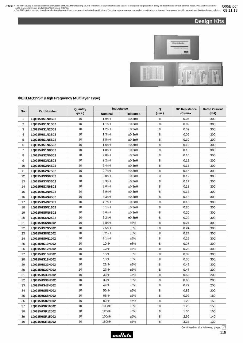
Design Kits
1
Part NumberNo.Rated Current
(mA)DC Resistance
(Ω) max.Q
(min.)ToleranceNominal
InductanceQuantity(pcs.)
oEKLMQ15SC (High Frequency Multilayer Type)
Continued on the following page.
LQG15HS1N0S02
LQG15HS1N1S02
LQG15HS1N2S02
LQG15HS1N3S02
LQG15HS1N5S02
LQG15HS1N6S02
LQG15HS1N8S02
LQG15HS2N0S02
LQG15HS2N2S02
LQG15HS2N4S02
LQG15HS2N7S02
LQG15HS3N0S02
LQG15HS3N3S02
LQG15HS3N6S02
LQG15HS3N9S02
LQG15HS4N3S02
LQG15HS4N7S02
LQG15HS5N1S02
LQG15HS5N6S02
LQG15HS6N2S02
LQG15HS6N8J02
LQG15HS7N5J02
LQG15HS8N2J02
LQG15HS9N1J02
LQG15HS10NJ02
LQG15HS12NJ02
LQG15HS15NJ02
LQG15HS18NJ02
LQG15HS22NJ02
LQG15HS27NJ02
LQG15HS33NJ02
LQG15HS39NJ02
LQG15HS47NJ02
LQG15HS56NJ02
LQG15HS68NJ02
LQG15HS82NJ02
LQG15HSR10J02
LQG15HSR12J02
LQG15HSR15J02
LQG15HSR18J02
1
2
3
4
5
6
7
8
9
10
11
12
13
14
15
16
17
18
19
20
21
22
23
24
25
26
27
28
29
30
31
32
33
34
35
36
37
38
39
40
300
300
300
300
300
300
300
300
300
300
300
300
300
300
300
300
300
300
300
300
300
300
300
300
300
300
300
300
300
300
200
200
200
200
180
150
150
150
140
130
0.07
0.09
0.09
0.09
0.10
0.10
0.10
0.10
0.12
0.15
0.15
0.17
0.17
0.18
0.18
0.18
0.18
0.20
0.20
0.22
0.24
0.24
0.24
0.26
0.26
0.28
0.32
0.36
0.42
0.46
0.58
0.65
0.72
0.82
0.92
1.20
1.25
1.30
2.99
3.38
8
8
8
8
8
8
8
8
8
8
8
8
8
8
8
8
8
8
8
8
8
8
8
8
8
8
8
8
8
8
8
8
8
8
8
8
8
8
8
8
±0.3nH
±0.3nH
±0.3nH
±0.3nH
±0.3nH
±0.3nH
±0.3nH
±0.3nH
±0.3nH
±0.3nH
±0.3nH
±0.3nH
±0.3nH
±0.3nH
±0.3nH
±0.3nH
±0.3nH
±0.3nH
±0.3nH
±0.3nH
±5%
±5%
±5%
±5%
±5%
±5%
±5%
±5%
±5%
±5%
±5%
±5%
±5%
±5%
±5%
±5%
±5%
±5%
±5%
±5%
1.0nH
1.1nH
1.2nH
1.3nH
1.5nH
1.6nH
1.8nH
2.0nH
2.2nH
2.4nH
2.7nH
3.0nH
3.3nH
3.6nH
3.9nH
4.3nH
4.7nH
5.1nH
5.6nH
6.2nH
6.8nH
7.5nH
8.2nH
9.1nH
10nH
12nH
15nH
18nH
22nH
27nH
33nH
39nH
47nH
56nH
68nH
82nH
100nH
120nH
150nH
180nH
10
10
10
10
10
10
10
10
10
10
10
10
10
10
10
10
10
10
10
10
10
10
10
10
10
10
10
10
10
10
10
10
10
10
10
10
10
10
10
10
Design Kits
!Note • Please read rating and !CAUTION (for storage, operating, rating, soldering, mounting and handling) in this catalog to prevent smoking and/or burning, etc.• This catalog has only typical specifications because there is no space for detailed specifications. Therefore, please approve our product specifications or transact the approval sheet for product specifications before ordering.
115
• This PDF catalog is downloaded from the website of Murata Manufacturing co., ltd. Therefore, it’s specifications are subject to change or our products in it may be discontinued without advance notice. Please check with our sales representatives or product engineers before ordering.
• This PDF catalog has only typical specifications because there is no space for detailed specifications. Therefore, please approve our product specifications or transact the approval sheet for product specifications before ordering.
!Note O05E.pdf09.11.13
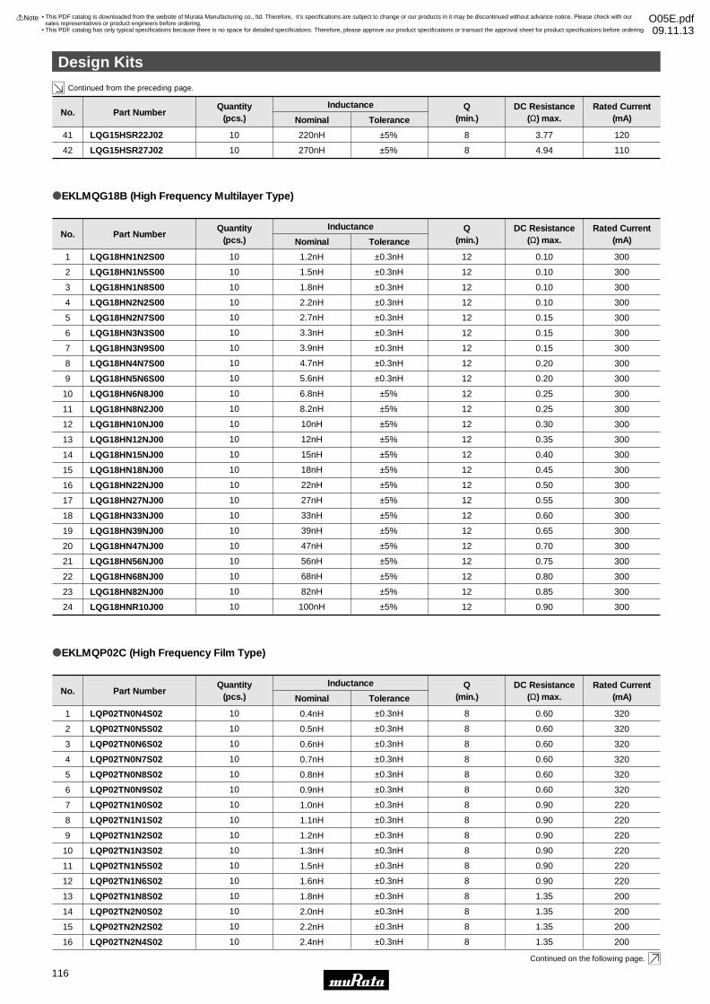
Design Kits
2
Continued from the preceding page.
Continued on the following page.
Part NumberNo.
LQG18HN1N2S00
LQG18HN1N5S00
LQG18HN1N8S00
LQG18HN2N2S00
1
2
3
4
Rated Current(mA)
300
300
300
300
DC Resistance(Ω) max.
0.10
0.10
0.10
0.10
Q(min.)
12
12
12
12
ToleranceNominal
±0.3nH
±0.3nH
±0.3nH
±0.3nH
Inductance
1.2nH
1.5nH
1.8nH
2.2nH
Quantity(pcs.)
10
10
10
10
oEKLMQG18B (High Frequency Multilayer Type)
Part NumberNo.
LQG15HSR22J02
LQG15HSR27J02
41
42
Rated Current(mA)
120
110
DC Resistance(Ω) max.
3.77
4.94
Q(min.)
8
8
ToleranceNominal
±5%
±5%
Inductance
220nH
270nH
Quantity(pcs.)
10
10
LQG18HN2N7S00
LQG18HN3N3S00
LQG18HN3N9S00
LQG18HN4N7S00
LQG18HN5N6S00
LQG18HN6N8J00
LQG18HN8N2J00
LQG18HN10NJ00
LQG18HN12NJ00
LQG18HN15NJ00
LQG18HN18NJ00
LQG18HN22NJ00
LQG18HN27NJ00
LQG18HN33NJ00
LQG18HN39NJ00
LQG18HN47NJ00
LQG18HN56NJ00
LQG18HN68NJ00
LQG18HN82NJ00
LQG18HNR10J00
5
6
7
8
9
10
11
12
13
14
15
16
17
18
19
20
21
22
23
24
300
300
300
300
300
300
300
300
300
300
300
300
300
300
300
300
300
300
300
300
0.15
0.15
0.15
0.20
0.20
0.25
0.25
0.30
0.35
0.40
0.45
0.50
0.55
0.60
0.65
0.70
0.75
0.80
0.85
0.90
12
12
12
12
12
12
12
12
12
12
12
12
12
12
12
12
12
12
12
12
±0.3nH
±0.3nH
±0.3nH
±0.3nH
±0.3nH
±5%
±5%
±5%
±5%
±5%
±5%
±5%
±5%
±5%
±5%
±5%
±5%
±5%
±5%
±5%
2.7nH
3.3nH
3.9nH
4.7nH
5.6nH
6.8nH
8.2nH
10nH
12nH
15nH
18nH
22nH
27nH
33nH
39nH
47nH
56nH
68nH
82nH
100nH
10
10
10
10
10
10
10
10
10
10
10
10
10
10
10
10
10
10
10
10
Part NumberNo.
LQP02TN0N4S02
LQP02TN0N5S02
LQP02TN0N6S02
LQP02TN0N7S02
LQP02TN0N8S02
LQP02TN0N9S02
LQP02TN1N0S02
LQP02TN1N1S02
LQP02TN1N2S02
LQP02TN1N3S02
LQP02TN1N5S02
LQP02TN1N6S02
LQP02TN1N8S02
LQP02TN2N0S02
LQP02TN2N2S02
LQP02TN2N4S02
1
2
3
4
5
6
7
8
9
10
11
12
13
14
15
16
Rated Current(mA)
320
320
320
320
320
320
220
220
220
220
220
220
200
200
200
200
DC Resistance(Ω) max.
0.60
0.60
0.60
0.60
0.60
0.60
0.90
0.90
0.90
0.90
0.90
0.90
1.35
1.35
1.35
1.35
Q(min.)
8
8
8
8
8
8
8
8
8
8
8
8
8
8
8
8
ToleranceNominal
±0.3nH
±0.3nH
±0.3nH
±0.3nH
±0.3nH
±0.3nH
±0.3nH
±0.3nH
±0.3nH
±0.3nH
±0.3nH
±0.3nH
±0.3nH
±0.3nH
±0.3nH
±0.3nH
InductanceQuantity(pcs.)
10
10
10
10
10
10
10
10
10
10
10
10
10
10
10
10
oEKLMQP02C (High Frequency Film Type)
0.4nH
0.5nH
0.6nH
0.7nH
0.8nH
0.9nH
1.0nH
1.1nH
1.2nH
1.3nH
1.5nH
1.6nH
1.8nH
2.0nH
2.2nH
2.4nH
Design Kits
!Note • Please read rating and !CAUTION (for storage, operating, rating, soldering, mounting and handling) in this catalog to prevent smoking and/or burning, etc.• This catalog has only typical specifications because there is no space for detailed specifications. Therefore, please approve our product specifications or transact the approval sheet for product specifications before ordering.
116
• This PDF catalog is downloaded from the website of Murata Manufacturing co., ltd. Therefore, it’s specifications are subject to change or our products in it may be discontinued without advance notice. Please check with our sales representatives or product engineers before ordering.
• This PDF catalog has only typical specifications because there is no space for detailed specifications. Therefore, please approve our product specifications or transact the approval sheet for product specifications before ordering.
!Note O05E.pdf09.11.13
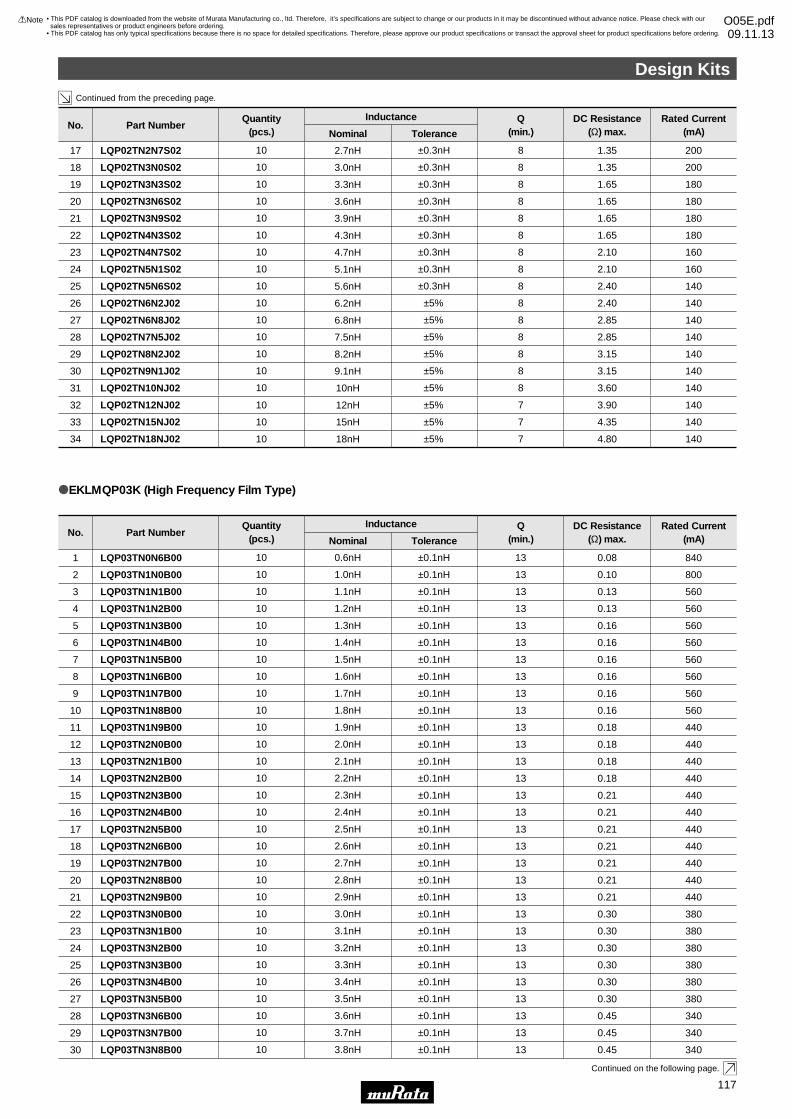
Design Kits
3
Continued from the preceding page.
Continued on the following page.
LQP03TN2N2B00
LQP03TN2N3B00
LQP03TN2N4B00
LQP03TN2N5B00
LQP03TN2N6B00
LQP03TN2N7B00
LQP03TN2N8B00
LQP03TN2N9B00
LQP03TN3N0B00
LQP03TN3N1B00
LQP03TN3N2B00
LQP03TN3N3B00
LQP03TN3N4B00
LQP03TN3N5B00
LQP03TN3N6B00
LQP03TN3N7B00
LQP03TN3N8B00
14
15
16
17
18
19
20
21
22
23
24
25
26
27
28
29
30
440
440
440
440
440
440
440
440
380
380
380
380
380
380
340
340
340
0.18
0.21
0.21
0.21
0.21
0.21
0.21
0.21
0.30
0.30
0.30
0.30
0.30
0.30
0.45
0.45
0.45
13
13
13
13
13
13
13
13
13
13
13
13
13
13
13
13
13
±0.1nH
±0.1nH
±0.1nH
±0.1nH
±0.1nH
±0.1nH
±0.1nH
±0.1nH
±0.1nH
±0.1nH
±0.1nH
±0.1nH
±0.1nH
±0.1nH
±0.1nH
±0.1nH
±0.1nH
2.2nH
2.3nH
2.4nH
2.5nH
2.6nH
2.7nH
2.8nH
2.9nH
3.0nH
3.1nH
3.2nH
3.3nH
3.4nH
3.5nH
3.6nH
3.7nH
3.8nH
10
10
10
10
10
10
10
10
10
10
10
10
10
10
10
10
10
Part NumberNo.
LQP03TN0N6B00
LQP03TN1N0B00
LQP03TN1N1B00
LQP03TN1N2B00
LQP03TN1N3B00
LQP03TN1N4B00
LQP03TN1N5B00
LQP03TN1N6B00
LQP03TN1N7B00
LQP03TN1N8B00
LQP03TN1N9B00
LQP03TN2N0B00
LQP03TN2N1B00
1
2
3
4
5
6
7
8
9
10
11
12
13
Rated Current(mA)
840
800
560
560
560
560
560
560
560
560
440
440
440
DC Resistance(Ω) max.
0.08
0.10
0.13
0.13
0.16
0.16
0.16
0.16
0.16
0.16
0.18
0.18
0.18
Q(min.)
13
13
13
13
13
13
13
13
13
13
13
13
13
ToleranceNominal
±0.1nH
±0.1nH
±0.1nH
±0.1nH
±0.1nH
±0.1nH
±0.1nH
±0.1nH
±0.1nH
±0.1nH
±0.1nH
±0.1nH
±0.1nH
Inductance
0.6nH
1.0nH
1.1nH
1.2nH
1.3nH
1.4nH
1.5nH
1.6nH
1.7nH
1.8nH
1.9nH
2.0nH
2.1nH
Quantity(pcs.)
10
10
10
10
10
10
10
10
10
10
10
10
10
oEKLMQP03K (High Frequency Film Type)
LQP02TN2N7S02
LQP02TN3N0S02
LQP02TN3N3S02
LQP02TN3N6S02
LQP02TN3N9S02
LQP02TN4N3S02
LQP02TN4N7S02
LQP02TN5N1S02
LQP02TN5N6S02
LQP02TN6N2J02
LQP02TN6N8J02
LQP02TN7N5J02
LQP02TN8N2J02
LQP02TN9N1J02
LQP02TN10NJ02
17
18
19
20
21
22
23
24
25
26
27
28
29
30
31
200
200
180
180
180
180
160
160
140
140
140
140
140
140
140
1.35
1.35
1.65
1.65
1.65
1.65
2.10
2.10
2.40
2.40
2.85
2.85
3.15
3.15
3.60
8
8
8
8
8
8
8
8
8
8
8
8
8
8
8
±0.3nH
±0.3nH
±0.3nH
±0.3nH
±0.3nH
±0.3nH
±0.3nH
±0.3nH
±0.3nH
±5%
±5%
±5%
±5%
±5%
±5%
10
10
10
10
10
10
10
10
10
10
10
10
10
10
10
2.7nH
3.0nH
3.3nH
3.6nH
3.9nH
4.3nH
4.7nH
5.1nH
5.6nH
6.2nH
6.8nH
7.5nH
8.2nH
9.1nH
10nH
LQP02TN12NJ02
LQP02TN15NJ02
LQP02TN18NJ02
32
33
34
140
140
140
3.90
4.35
4.80
7
7
7
±5%
±5%
±5%
10
10
10
12nH
15nH
18nH
Part NumberNo.Rated Current
(mA)DC Resistance
(Ω) max.Q
(min.)ToleranceNominal
InductanceQuantity(pcs.)
Design Kits
!Note • Please read rating and !CAUTION (for storage, operating, rating, soldering, mounting and handling) in this catalog to prevent smoking and/or burning, etc.• This catalog has only typical specifications because there is no space for detailed specifications. Therefore, please approve our product specifications or transact the approval sheet for product specifications before ordering.
117
• This PDF catalog is downloaded from the website of Murata Manufacturing co., ltd. Therefore, it’s specifications are subject to change or our products in it may be discontinued without advance notice. Please check with our sales representatives or product engineers before ordering.
• This PDF catalog has only typical specifications because there is no space for detailed specifications. Therefore, please approve our product specifications or transact the approval sheet for product specifications before ordering.
!Note O05E.pdf09.11.13
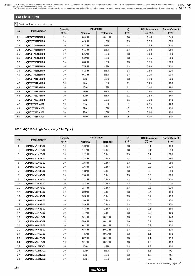
Design Kits
4
Continued from the preceding page.
Continued on the following page.
LQP15MN3N0B02
LQP15MN3N3B02
LQP15MN3N6B02
LQP15MN3N9B02
LQP15MN4N3B02
LQP15MN4N7B02
LQP15MN5N1B02
LQP15MN5N6B02
LQP15MN6N2B02
LQP15MN6N8B02
LQP15MN7N5B02
LQP15MN8N2B02
LQP15MN9N1B02
12
13
14
15
16
17
18
19
20
21
22
23
24
190
190
170
170
160
160
140
140
130
130
110
110
100
0.4
0.4
0.5
0.5
0.6
0.6
0.7
0.7
0.9
0.9
1.1
1.1
1.3
13
13
13
13
13
13
13
13
13
13
13
13
13
0.1nH
0.1nH
0.1nH
0.1nH
0.1nH
0.1nH
±0.1nH
±0.1nH
±0.1nH
±0.1nH
±0.1nH
±0.1nH
±0.1nH
3.0nH
3.3nH
3.6nH
3.9nH
4.3nH
4.7nH
5.1nH
5.6nH
6.2nH
6.8nH
7.5nH
8.2nH
9.1nH
10
10
10
10
10
10
10
10
10
10
10
10
10
Part NumberNo.
LQP15MN1N0B02
LQP15MN1N1B02
LQP15MN1N2B02
LQP15MN1N3B02
LQP15MN1N5B02
LQP15MN1N6B02
LQP15MN1N8B02
LQP15MN2N0B02
LQP15MN2N2B02
LQP15MN2N4B02
LQP15MN2N7B02
1
2
3
4
5
6
7
8
9
10
11
Rated Current(mA)
400
390
390
280
280
220
280
220
220
220
220
DC Resistance(Ω) max.
0.1
0.1
0.1
0.2
0.2
0.3
0.2
0.3
0.3
0.3
0.3
Q(min.)
13
13
13
13
13
13
13
13
13
13
13
ToleranceNominal
0.1nH
0.1nH
0.1nH
0.1nH
0.1nH
0.1nH
0.1nH
0.1nH
0.1nH
0.1nH
0.1nH
Inductance
1.0nH
1.1nH
1.2nH
1.3nH
1.5nH
1.6nH
1.8nH
2.0nH
2.2nH
2.4nH
2.7nH
Quantity(pcs.)
10
10
10
10
10
10
10
10
10
10
10
oEKLMQP15B (High Frequency Film Type)
Part NumberNo.Rated Current
(mA)DC Resistance
(Ω) max.Q
(min.)ToleranceNominal
InductanceQuantity(pcs.)
LQP03TN5N1H00
LQP03TN5N6H00
LQP03TN6N2H00
LQP03TN6N8H00
LQP03TN7N5H00
LQP03TN8N2H00
LQP03TN9N1H00
LQP03TN10NH00
LQP03TN12NH00
LQP03TN15NH00
LQP03TN18NH00
LQP03TN22NH00
LQP03TN27NH00
LQP03TN33NJ00
LQP03TN39NJ00
LQP03TN47NJ00
LQP03TN56NJ00
34
35
36
37
38
39
40
41
42
43
44
45
46
47
48
49
50
280
280
260
260
220
220
200
200
180
180
160
140
140
120
120
100
100
0.68
0.68
0.75
0.75
0.86
0.86
1.10
1.10
1.25
1.40
1.60
2.55
2.90
2.95
3.35
3.60
4.30
13
13
13
13
13
13
13
13
11
11
11
11
11
8
8
8
8
±3%
±3%
±3%
±3%
±3%
±3%
±3%
±3%
±3%
±3%
±3%
±3%
±3%
±5%
±5%
±5%
±5%
5.1nH
5.6nH
6.2nH
6.8nH
7.5nH
8.2nH
9.1nH
10nH
12nH
15nH
18nH
22nH
27nH
33nH
39nH
47nH
56nH
10
10
10
10
10
10
10
10
10
10
10
10
10
10
10
10
10
LQP03TN3N9B00
LQP03TN4N3H00
LQP03TN4N7H00
31
32
33
340
320
320
0.45
0.55
0.55
13
13
13
±0.1nH
±3%
±3%
3.9nH
4.3nH
4.7nH
10
10
10
LQP15MN10NG02
LQP15MN12NG02
25
26
100
90
1.3
1.6
13
13
±2%
±2%
10nH
12nH
10
10
LQP15MN15NG0227 901.813±2%15nH10
LQP15MN18NG0228 802.013±2%18nH10
Design Kits
!Note • Please read rating and !CAUTION (for storage, operating, rating, soldering, mounting and handling) in this catalog to prevent smoking and/or burning, etc.• This catalog has only typical specifications because there is no space for detailed specifications. Therefore, please approve our product specifications or transact the approval sheet for product specifications before ordering.
118
• This PDF catalog is downloaded from the website of Murata Manufacturing co., ltd. Therefore, it’s specifications are subject to change or our products in it may be discontinued without advance notice. Please check with our sales representatives or product engineers before ordering.
• This PDF catalog has only typical specifications because there is no space for detailed specifications. Therefore, please approve our product specifications or transact the approval sheet for product specifications before ordering.
!Note O05E.pdf09.11.13
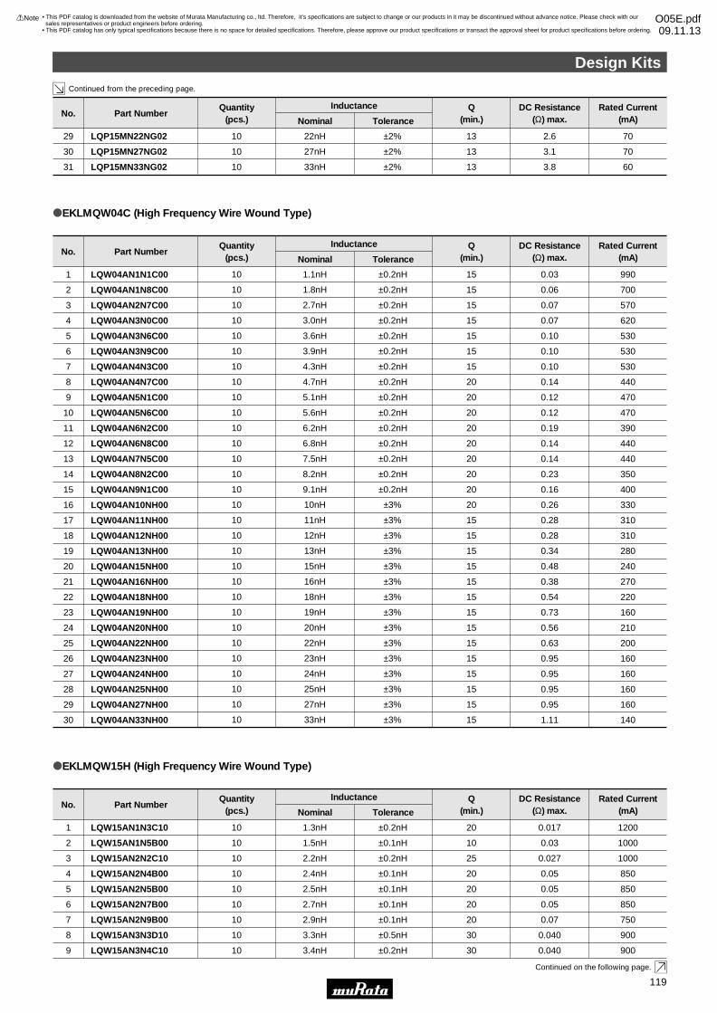
Design Kits
5
Continued from the preceding page.
Continued on the following page.
LQW15AN1N3C10
LQW15AN1N5B00
LQW15AN2N2C10
LQW15AN2N4B00
LQW15AN2N5B00
1
2
3
4
5
1200
1000
1000
850
850
0.017
0.03
0.027
0.05
0.05
20
10
25
20
20
±0.2nH
±0.1nH
±0.2nH
±0.1nH
±0.1nH
1.3nH
1.5nH
2.2nH
2.4nH
2.5nH
10
10
10
10
10
oEKLMQW15H (High Frequency Wire Wound Type)
Part NumberNo.Rated Current
(mA)DC Resistance
(Ω) max.Q
(min.)ToleranceNominal
InductanceQuantity(pcs.)
LQW04AN10NH00
LQW04AN11NH00
LQW04AN12NH00
LQW04AN13NH00
LQW04AN15NH00
LQW04AN16NH00
LQW04AN18NH00
LQW04AN19NH00
LQW04AN20NH00
LQW04AN22NH00
LQW04AN23NH00
LQW04AN24NH00
LQW04AN25NH00
LQW04AN27NH00
LQW04AN33NH00
16
17
18
19
20
21
22
23
24
25
26
27
28
29
30
330
310
310
280
240
270
220
160
210
200
160
160
160
160
140
0.26
0.28
0.28
0.34
0.48
0.38
0.54
0.73
0.56
0.63
0.95
0.95
0.95
0.95
1.11
20
15
15
15
15
15
15
15
15
15
15
15
15
15
15
±3%
±3%
±3%
±3%
±3%
±3%
±3%
±3%
±3%
±3%
±3%
±3%
±3%
±3%
±3%
10nH
11nH
12nH
13nH
15nH
16nH
18nH
19nH
20nH
22nH
23nH
24nH
25nH
27nH
33nH
10
10
10
10
10
10
10
10
10
10
10
10
10
10
10
LQW04AN5N6C00
LQW04AN6N2C00
LQW04AN6N8C00
LQW04AN7N5C00
LQW04AN8N2C00
LQW04AN9N1C00
10
11
12
13
14
15
470
390
440
440
350
400
0.12
0.19
0.14
0.14
0.23
0.16
20
20
20
20
20
20
±0.2nH
±0.2nH
±0.2nH
±0.2nH
±0.2nH
±0.2nH
5.6nH
6.2nH
6.8nH
7.5nH
8.2nH
9.1nH
10
10
10
10
10
10
oEKLMQW04C (High Frequency Wire Wound Type)
LQW04AN1N1C00
LQW04AN1N8C00
LQW04AN2N7C00
LQW04AN3N0C00
LQW04AN3N6C00
LQW04AN3N9C00
LQW04AN4N3C00
LQW04AN4N7C00
LQW04AN5N1C00
1
2
3
4
5
6
7
8
9
990
700
570
620
530
530
530
440
470
0.03
0.06
0.07
0.07
0.10
0.10
0.10
0.14
0.12
15
15
15
15
15
15
15
20
20
±0.2nH
±0.2nH
±0.2nH
±0.2nH
±0.2nH
±0.2nH
±0.2nH
±0.2nH
±0.2nH
1.1nH
1.8nH
2.7nH
3.0nH
3.6nH
3.9nH
4.3nH
4.7nH
5.1nH
10
10
10
10
10
10
10
10
10
Part NumberNo.Rated Current
(mA)DC Resistance
(Ω) max.Q
(min.)ToleranceNominal
InductanceQuantity(pcs.)
Part NumberNo.Rated Current
(mA)DC Resistance
(Ω) max.Q
(min.)ToleranceNominal
InductanceQuantity(pcs.)
LQP15MN22NG02
LQP15MN27NG02
LQP15MN33NG02
29
30
31
70
70
60
2.6
3.1
3.8
13
13
13
±2%
±2%
±2%
22nH
27nH
33nH
10
10
10
LQW15AN3N4C109 9000.04030±0.2nH3.4nH10
LQW15AN2N7B00
LQW15AN2N9B00
LQW15AN3N3D10
6
7
8
850
750
900
0.05
0.07
0.040
20
20
30
±0.1nH
±0.1nH
±0.5nH
2.7nH
2.9nH
3.3nH
10
10
10
Design Kits
!Note • Please read rating and !CAUTION (for storage, operating, rating, soldering, mounting and handling) in this catalog to prevent smoking and/or burning, etc.• This catalog has only typical specifications because there is no space for detailed specifications. Therefore, please approve our product specifications or transact the approval sheet for product specifications before ordering.
119
• This PDF catalog is downloaded from the website of Murata Manufacturing co., ltd. Therefore, it’s specifications are subject to change or our products in it may be discontinued without advance notice. Please check with our sales representatives or product engineers before ordering.
• This PDF catalog has only typical specifications because there is no space for detailed specifications. Therefore, please approve our product specifications or transact the approval sheet for product specifications before ordering.
!Note O05E.pdf09.11.13
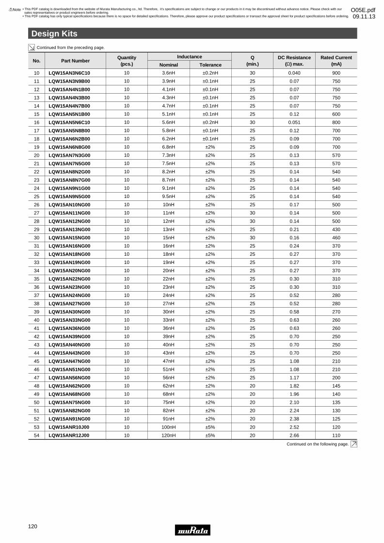
Design Kits
6
Continued from the preceding page.
Continued on the following page.
LQW15ANR10J00
LQW15ANR12J00
53
54
120
110
2.52
2.66
20
20
±5%
±5%
100nH
120nH
10
10
LQW15AN27NG00
LQW15AN30NG00
LQW15AN33NG00
LQW15AN36NG00
LQW15AN39NG00
LQW15AN40NG00
LQW15AN43NG00
LQW15AN47NG00
LQW15AN51NG00
LQW15AN56NG00
LQW15AN62NG00
LQW15AN68NG00
LQW15AN75NG00
LQW15AN82NG00
LQW15AN91NG00
38
39
40
41
42
43
44
45
46
47
48
49
50
51
52
280
270
260
260
250
250
250
210
210
200
145
140
135
130
125
0.52
0.58
0.63
0.63
0.70
0.70
0.70
1.08
1.08
1.17
1.82
1.96
2.10
2.24
2.38
25
25
25
25
25
25
25
25
25
25
20
20
20
20
20
±2%
±2%
±2%
±2%
±2%
±2%
±2%
±2%
±2%
±2%
±2%
±2%
±2%
±2%
±2%
27nH
30nH
33nH
36nH
39nH
40nH
43nH
47nH
51nH
56nH
62nH
68nH
75nH
82nH
91nH
10
10
10
10
10
10
10
10
10
10
10
10
10
10
10
LQW15AN12NG00
LQW15AN13NG00
LQW15AN15NG00
LQW15AN16NG00
LQW15AN18NG00
LQW15AN19NG00
LQW15AN20NG00
LQW15AN22NG00
LQW15AN23NG00
LQW15AN24NG00
28
29
30
31
32
33
34
35
36
37
500
430
460
370
370
370
370
310
310
280
0.14
0.21
0.16
0.24
0.27
0.27
0.27
0.30
0.30
0.52
30
25
30
25
25
25
25
25
25
25
±2%
±2%
±2%
±2%
±2%
±2%
±2%
±2%
±2%
±2%
12nH
13nH
15nH
16nH
18nH
19nH
20nH
22nH
23nH
24nH
10
10
10
10
10
10
10
10
10
10
Part NumberNo.Rated Current
(mA)DC Resistance
(Ω) max.Q
(min.)ToleranceNominal
InductanceQuantity(pcs.)
LQW15AN3N6C10
LQW15AN3N9B00
LQW15AN4N1B00
LQW15AN4N3B00
LQW15AN4N7B00
LQW15AN5N1B00
LQW15AN5N6C10
LQW15AN5N8B00
LQW15AN6N2B00
LQW15AN6N8G00
LQW15AN7N3G00
LQW15AN7N5G00
LQW15AN8N2G00
LQW15AN8N7G00
LQW15AN9N1G00
LQW15AN9N5G00
LQW15AN10NG00
LQW15AN11NG00
10
11
12
13
14
15
16
17
18
19
20
21
22
23
24
25
26
27
900
750
750
750
750
600
800
700
700
700
570
570
540
540
540
540
500
500
0.040
0.07
0.07
0.07
0.07
0.12
0.051
0.12
0.09
0.09
0.13
0.13
0.14
0.14
0.14
0.14
0.17
0.14
30
25
25
25
25
25
30
25
25
25
25
25
25
25
25
25
25
30
±0.2nH
±0.1nH
±0.1nH
±0.1nH
±0.1nH
±0.1nH
±0.2nH
±0.1nH
±0.1nH
±2%
±2%
±2%
±2%
±2%
±2%
±2%
±2%
±2%
3.6nH
3.9nH
4.1nH
4.3nH
4.7nH
5.1nH
5.6nH
5.8nH
6.2nH
6.8nH
7.3nH
7.5nH
8.2nH
8.7nH
9.1nH
9.5nH
10nH
11nH
10
10
10
10
10
10
10
10
10
10
10
10
10
10
10
10
10
10
Design Kits
!Note • Please read rating and !CAUTION (for storage, operating, rating, soldering, mounting and handling) in this catalog to prevent smoking and/or burning, etc.• This catalog has only typical specifications because there is no space for detailed specifications. Therefore, please approve our product specifications or transact the approval sheet for product specifications before ordering.
120
• This PDF catalog is downloaded from the website of Murata Manufacturing co., ltd. Therefore, it’s specifications are subject to change or our products in it may be discontinued without advance notice. Please check with our sales representatives or product engineers before ordering.
• This PDF catalog has only typical specifications because there is no space for detailed specifications. Therefore, please approve our product specifications or transact the approval sheet for product specifications before ordering.
!Note O05E.pdf09.11.13
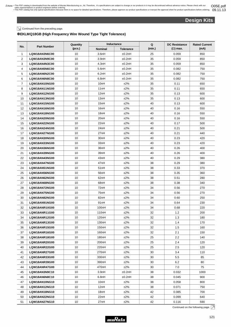
Design Kits
7
Continued from the preceding page.
Continued on the following page.
LQW18AN10NG10
LQW18AN12NG10
LQW18AN18NG10
LQW18AN22NG10
LQW18AN27NG10
47
48
49
50
51
800
750
700
640
590
0.058
0.071
0.085
0.099
0.116
38
38
42
42
42
±2%
±2%
±2%
±2%
±2%
10nH
12nH
18nH
22nH
27nH
10
10
10
10
10
LQW18ANR10G00
LQW18ANR11G00
LQW18ANR12G00
LQW18ANR13G00
LQW18ANR15G00
LQW18ANR16G00
LQW18ANR18G00
LQW18ANR20G00
LQW18ANR22G00
LQW18ANR27G00
LQW18ANR33G00
LQW18ANR39G00
LQW18ANR47G00
LQW18AN3N9C10
LQW18AN6N8C10
32
33
34
35
36
37
38
39
40
41
42
43
44
45
46
220
200
180
170
160
150
140
120
120
110
85
80
75
1000
900
0.68
1.2
1.3
1.4
1.5
2.1
2.2
2.4
2.5
3.4
5.5
6.2
7.0
0.032
0.045
34
32
32
32
32
32
25
25
25
30
30
30
30
38
38
±2%
±2%
±2%
±2%
±2%
±2%
±2%
±2%
±2%
±2%
±2%
±2%
±2%
±0.2nH
±0.2nH
100nH
110nH
120nH
130nH
150nH
160nH
180nH
200nH
220nH
270nH
330nH
390nH
470nH
3.9nH
6.8nH
10
10
10
10
10
10
10
10
10
10
10
10
10
10
10
LQW18AN43NG00
LQW18AN47NG00
LQW18AN51NG00
LQW18AN56NG00
LQW18AN62NG00
LQW18AN68NG00
LQW18AN72NG00
LQW18AN75NG00
LQW18AN82NG00
LQW18AN91NG00
22
23
24
25
26
27
28
29
30
31
380
380
370
360
280
340
270
270
250
230
0.29
0.29
0.33
0.35
0.51
0.38
0.56
0.56
0.60
0.64
40
38
38
38
38
38
34
34
34
34
±2%
±2%
±2%
±2%
±2%
±2%
±2%
±2%
±2%
±2%
43nH
47nH
51nH
56nH
62nH
68nH
72nH
75nH
82nH
91nH
10
10
10
10
10
10
10
10
10
10
LQW18AN4N3C00
LQW18AN5N6C00
LQW18AN6N2C00
LQW18AN6N8C00
LQW18AN10NG00
LQW18AN11NG00
LQW18AN12NG00
LQW18AN13NG00
LQW18AN15NG00
LQW18AN16NG00
LQW18AN18NG00
LQW18AN20NG00
LQW18AN22NG00
LQW18AN24NG00
LQW18AN27NG00
LQW18AN30NG00
LQW18AN33NG00
LQW18AN36NG00
LQW18AN39NG00
3
4
5
6
7
8
9
10
11
12
13
14
15
16
17
18
19
20
21
850
750
750
750
650
650
600
600
600
550
550
550
500
500
440
420
420
400
400
0.059
0.082
0.082
0.082
0.11
0.11
0.13
0.13
0.13
0.16
0.16
0.16
0.17
0.21
0.21
0.23
0.23
0.26
0.26
35
35
35
35
35
35
35
35
40
40
40
40
40
40
40
40
40
40
40
±0.2nH
±0.2nH
±0.2nH
±0.2nH
±2%
±2%
±2%
±2%
±2%
±2%
±2%
±2%
±2%
±2%
±2%
±2%
±2%
±2%
±2%
4.3nH
5.6nH
6.2nH
6.8nH
10nH
11nH
12nH
13nH
15nH
16nH
18nH
20nH
22nH
24nH
27nH
30nH
33nH
36nH
39nH
10
10
10
10
10
10
10
10
10
10
10
10
10
10
10
10
10
10
10
Part NumberNo.
LQW18AN3N6C00
LQW18AN3N9C00
1
2
Rated Current(mA)
850
850
DC Resistance(Ω) max.
0.059
0.059
Q(min.)
25
35
ToleranceNominal
±0.2nH
±0.2nH
Inductance
3.6nH
3.9nH
Quantity(pcs.)
10
10
oEKLMQ18GB (High Frequency Wire Wound Type Tight Tolerance)
Design Kits
!Note • Please read rating and !CAUTION (for storage, operating, rating, soldering, mounting and handling) in this catalog to prevent smoking and/or burning, etc.• This catalog has only typical specifications because there is no space for detailed specifications. Therefore, please approve our product specifications or transact the approval sheet for product specifications before ordering.
121
• This PDF catalog is downloaded from the website of Murata Manufacturing co., ltd. Therefore, it’s specifications are subject to change or our products in it may be discontinued without advance notice. Please check with our sales representatives or product engineers before ordering.
• This PDF catalog has only typical specifications because there is no space for detailed specifications. Therefore, please approve our product specifications or transact the approval sheet for product specifications before ordering.
!Note O05E.pdf09.11.13
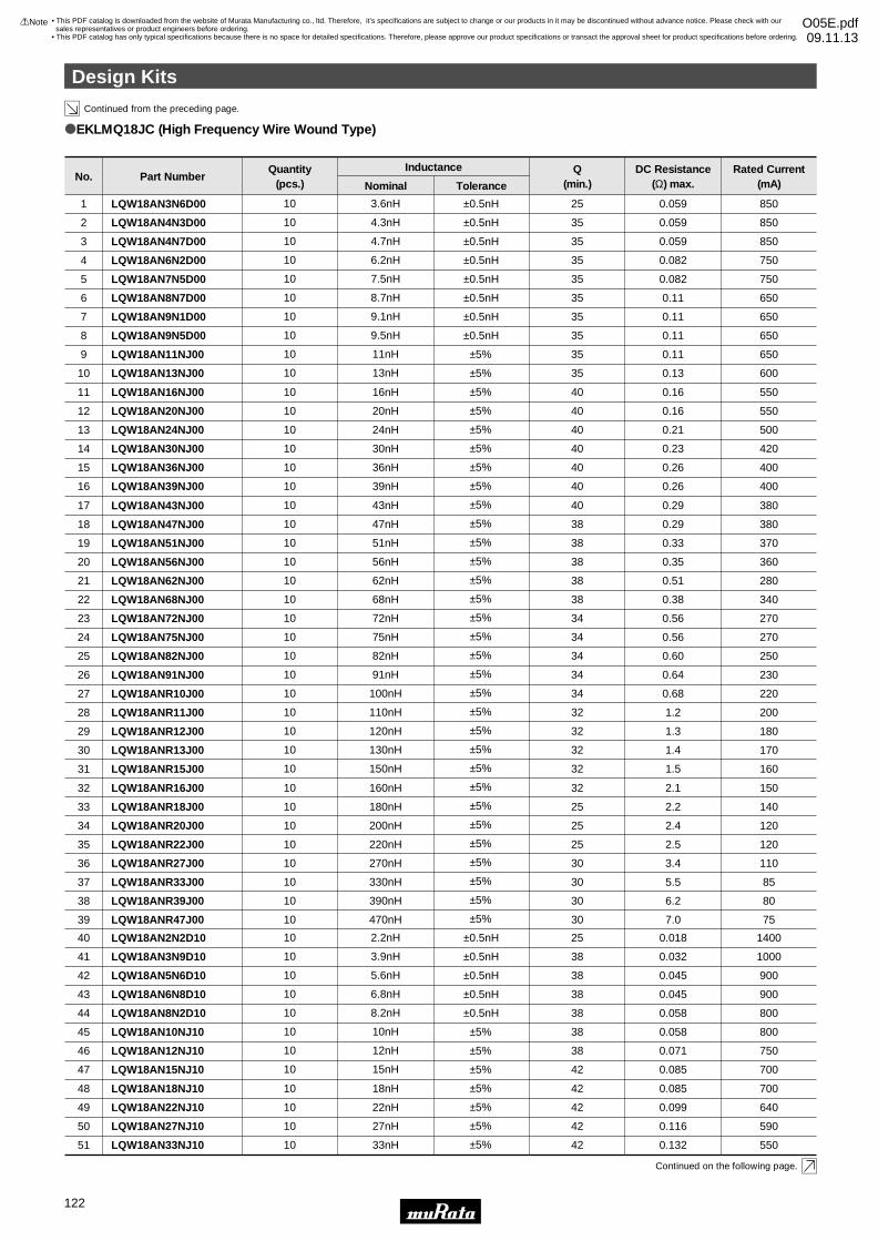
Design Kits
8
Continued from the preceding page.
Continued on the following page.
Part NumberNo.Rated Current
(mA)DC Resistance
(Ω) max.Q
(min.)ToleranceNominal
InductanceQuantity(pcs.)
oEKLMQ18JC (High Frequency Wire Wound Type)
LQW18ANR16J00
LQW18ANR18J00
LQW18ANR20J00
LQW18ANR22J00
LQW18ANR27J00
LQW18ANR33J00
LQW18ANR39J00
LQW18ANR47J00
32
33
34
35
36
37
38
39
150
140
120
120
110
85
80
75
2.1
2.2
2.4
2.5
3.4
5.5
6.2
7.0
32
25
25
25
30
30
30
30
160nH
180nH
200nH
220nH
270nH
330nH
390nH
470nH
10
10
10
10
10
10
10
10
LQW18AN43NJ00
LQW18AN47NJ00
LQW18AN51NJ00
LQW18AN56NJ00
LQW18AN62NJ00
LQW18AN68NJ00
LQW18AN72NJ00
LQW18AN75NJ00
LQW18AN82NJ00
LQW18AN91NJ00
LQW18ANR10J00
LQW18ANR11J00
LQW18ANR12J00
LQW18ANR13J00
LQW18ANR15J00
17
18
19
20
21
22
23
24
25
26
27
28
29
30
31
380
380
370
360
280
340
270
270
250
230
220
200
180
170
160
0.29
0.29
0.33
0.35
0.51
0.38
0.56
0.56
0.60
0.64
0.68
1.2
1.3
1.4
1.5
40
38
38
38
38
38
34
34
34
34
34
32
32
32
32
43nH
47nH
51nH
56nH
62nH
68nH
72nH
75nH
82nH
91nH
100nH
110nH
120nH
130nH
150nH
10
10
10
10
10
10
10
10
10
10
10
10
10
10
10
LQW18AN16NJ00
LQW18AN18NJ10
LQW18AN20NJ00
LQW18AN22NJ10
LQW18AN24NJ00
LQW18AN27NJ10
LQW18AN30NJ00
LQW18AN33NJ10
LQW18AN36NJ00
LQW18AN39NJ00
11
48
12
49
13
50
14
51
15
16
550
700
550
640
500
590
420
550
400
400
0.16
0.085
0.16
0.099
0.21
0.116
0.23
0.132
0.26
0.26
40
42
40
42
40
42
40
42
40
40
16nH
18nH
20nH
22nH
24nH
27nH
30nH
33nH
36nH
39nH
10
10
10
10
10
10
10
10
10
10
LQW18AN2N2D10
LQW18AN3N6D00
LQW18AN3N9D10
LQW18AN4N3D00
LQW18AN4N7D00
LQW18AN5N6D10
LQW18AN6N2D00
LQW18AN6N8D10
LQW18AN7N5D00
LQW18AN8N2D10
LQW18AN8N7D00
LQW18AN9N1D00
LQW18AN9N5D00
LQW18AN10NJ10
LQW18AN11NJ00
LQW18AN12NJ10
LQW18AN13NJ00
LQW18AN15NJ10
40
1
41
2
3
42
4
43
5
44
6
7
8
45
9
46
10
47
1400
850
1000
850
850
900
750
900
750
800
650
650
650
800
650
750
600
700
0.018
0.059
0.032
0.059
0.059
0.045
0.082
0.045
0.082
0.058
0.11
0.11
0.11
0.058
0.11
0.071
0.13
0.085
25
25
38
35
35
38
35
38
35
38
35
35
35
38
35
38
35
42
±0.5nH
±0.5nH
±0.5nH
±0.5nH
±0.5nH
±0.5nH
±0.5nH
±0.5nH
±0.5nH
±0.5nH
±0.5nH
±0.5nH
±0.5nH
±5%
±5%
±5%
±5%
±5%
±5%
±5%
±5%
±5%
±5%
±5%
±5%
±5%
±5%
±5%
±5%
±5%
±5%
±5%
±5%
±5%
±5%
±5%
±5%
±5%
±5%
±5%
±5%
±5%
±5%
±5%
±5%
±5%
±5%
±5%
±5%
±5%
±5%
2.2nH
3.6nH
3.9nH
4.3nH
4.7nH
5.6nH
6.2nH
6.8nH
7.5nH
8.2nH
8.7nH
9.1nH
9.5nH
10nH
11nH
12nH
13nH
15nH
10
10
10
10
10
10
10
10
10
10
10
10
10
10
10
10
10
10
Design Kits
!Note • Please read rating and !CAUTION (for storage, operating, rating, soldering, mounting and handling) in this catalog to prevent smoking and/or burning, etc.• This catalog has only typical specifications because there is no space for detailed specifications. Therefore, please approve our product specifications or transact the approval sheet for product specifications before ordering.
122
• This PDF catalog is downloaded from the website of Murata Manufacturing co., ltd. Therefore, it’s specifications are subject to change or our products in it may be discontinued without advance notice. Please check with our sales representatives or product engineers before ordering.
• This PDF catalog has only typical specifications because there is no space for detailed specifications. Therefore, please approve our product specifications or transact the approval sheet for product specifications before ordering.
!Note O05E.pdf09.11.13
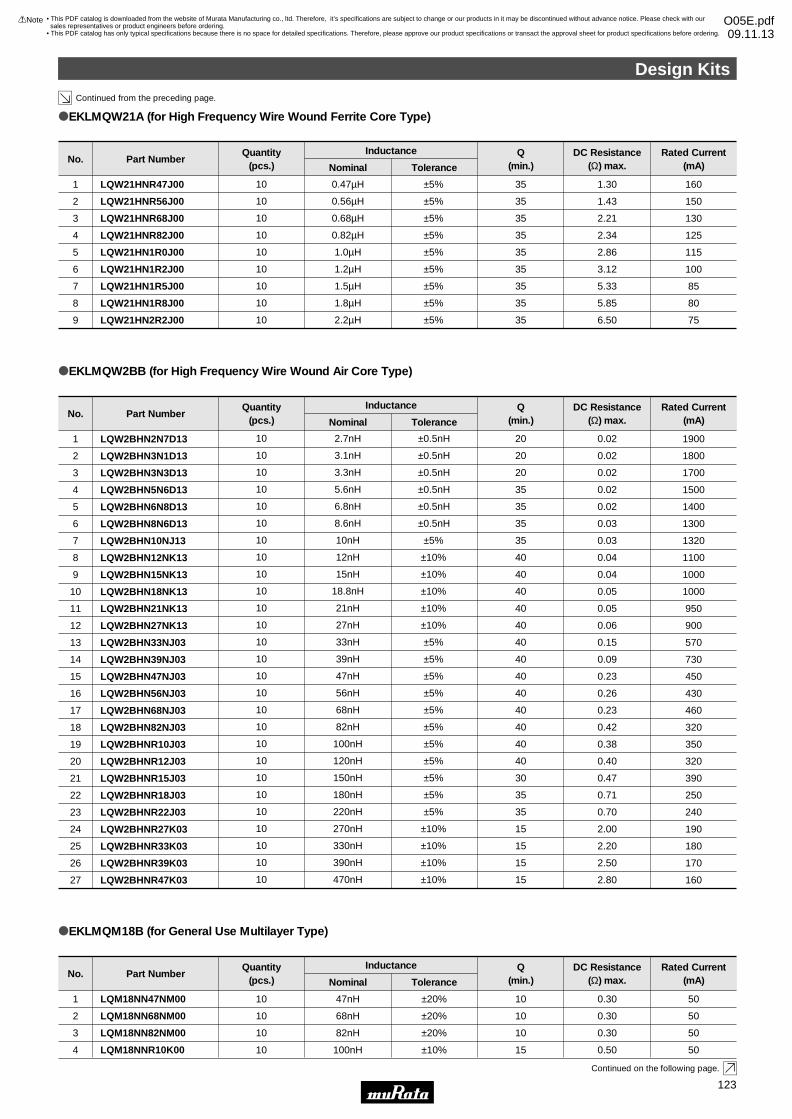
Design Kits
9
Continued from the preceding page.
Continued on the following page.
Part NumberNo.Rated Current
(mA)DC Resistance
(Ω) max.Q
(min.)ToleranceNominal
InductanceQuantity(pcs.)
LQM18NN47NM00
LQM18NN68NM00
LQM18NN82NM00
1
2
3
50
50
50
0.30
0.30
0.30
10
10
10
±20%
±20%
±20%
47nH
68nH
82nH
10
10
10
oEKLMQM18B (for General Use Multilayer Type)
LQM18NNR10K004 500.5015±10%100nH10
Part NumberNo.ToleranceNominal
InductanceQuantity(pcs.)
LQW21HNR47J00
LQW21HNR56J00
LQW21HNR68J00
LQW21HNR82J00
LQW21HN1R0J00
LQW21HN1R2J00
LQW21HN1R5J00
LQW21HN1R8J00
LQW21HN2R2J00
1
2
3
4
5
6
7
8
9
160
150
130
125
115
100
85
80
75
1.30
1.43
2.21
2.34
2.86
3.12
5.33
5.85
6.50
35
35
35
35
35
35
35
35
35
±5%
±5%
±5%
±5%
±5%
±5%
±5%
±5%
±5%
0.47µH
0.56µH
0.68µH
0.82µH
1.0µH
1.2µH
1.5µH
1.8µH
2.2µH
10
10
10
10
10
10
10
10
10
oEKLMQW21A (for High Frequency Wire Wound Ferrite Core Type)
Rated Current(mA)
DC Resistance(Ω) max.
Q(min.)
Part NumberNo.ToleranceNominal
InductanceQuantity(pcs.)
LQW2BHN2N7D13
LQW2BHN3N1D13
LQW2BHN3N3D13
LQW2BHN5N6D13
LQW2BHN6N8D13
LQW2BHN8N6D13
LQW2BHN10NJ13
LQW2BHN12NK13
LQW2BHN15NK13
LQW2BHN18NK13
LQW2BHN21NK13
LQW2BHN27NK13
LQW2BHN33NJ03
LQW2BHN39NJ03
LQW2BHN47NJ03
LQW2BHN56NJ03
LQW2BHN68NJ03
LQW2BHN82NJ03
LQW2BHNR10J03
LQW2BHNR12J03
LQW2BHNR15J03
LQW2BHNR18J03
LQW2BHNR22J03
LQW2BHNR27K03
LQW2BHNR33K03
LQW2BHNR39K03
LQW2BHNR47K03
1
2
3
4
5
6
7
8
9
10
11
12
13
14
15
16
17
18
19
20
21
22
23
24
25
26
27
1900
1800
1700
1500
1400
1300
1320
1100
1000
1000
950
900
570
730
450
430
460
320
350
320
390
250
240
190
180
170
160
0.02
0.02
0.02
0.02
0.02
0.03
0.03
0.04
0.04
0.05
0.05
0.06
0.15
0.09
0.23
0.26
0.23
0.42
0.38
0.40
0.47
0.71
0.70
2.00
2.20
2.50
2.80
20
20
20
35
35
35
35
40
40
40
40
40
40
40
40
40
40
40
40
40
30
35
35
15
15
15
15
±0.5nH
±0.5nH
±0.5nH
±0.5nH
±0.5nH
±0.5nH
±5%
±10%
±10%
±10%
±10%
±10%
±5%
±5%
±5%
±5%
±5%
±5%
±5%
±5%
±5%
±5%
±5%
±10%
±10%
±10%
±10%
2.7nH
3.1nH
3.3nH
5.6nH
6.8nH
8.6nH
10nH
12nH
15nH
18.8nH
21nH
27nH
33nH
39nH
47nH
56nH
68nH
82nH
100nH
120nH
150nH
180nH
220nH
270nH
330nH
390nH
470nH
10
10
10
10
10
10
10
10
10
10
10
10
10
10
10
10
10
10
10
10
10
10
10
10
10
10
10
oEKLMQW2BB (for High Frequency Wire Wound Air Core Type)
Rated Current(mA)
DC Resistance(Ω) max.
Q(min.)
Design Kits
!Note • Please read rating and !CAUTION (for storage, operating, rating, soldering, mounting and handling) in this catalog to prevent smoking and/or burning, etc.• This catalog has only typical specifications because there is no space for detailed specifications. Therefore, please approve our product specifications or transact the approval sheet for product specifications before ordering.
123
• This PDF catalog is downloaded from the website of Murata Manufacturing co., ltd. Therefore, it’s specifications are subject to change or our products in it may be discontinued without advance notice. Please check with our sales representatives or product engineers before ordering.
• This PDF catalog has only typical specifications because there is no space for detailed specifications. Therefore, please approve our product specifications or transact the approval sheet for product specifications before ordering.
!Note O05E.pdf09.11.13
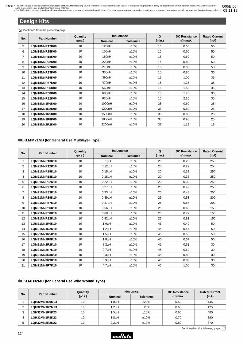
Design Kits
10
Continued from the preceding page.
Continued on the following page.
oEKLMH32MC (for General Use Wire Wound Type)
Part NumberNo.
LQH32MN1R0M23
LQH32MN1R2M23
LQH32MN1R5K23
LQH32MN1R8K23
LQH32MN2R2K23
1
2
3
4
5
Rated Current(mA)
445
425
400
390
370
DC Resistance(Ω) max.
0.50
0.60
0.60
0.70
0.80
ToleranceNominal
±20%
±20%
±10%
±10%
±10%
Inductance
1.0µH
1.2µH
1.5µH
1.8µH
2.2µH
Quantity(pcs.)
10
10
10
10
10
Part NumberNo.Rated Current
(mA)DC Resistance
(Ω) max.Q
(min.)ToleranceNominal
InductanceQuantity(pcs.)
LQM21NNR10K10
LQM21NNR12K10
1
2
250
250
0.26
0.29
20
20
±10%
±10%
0.1µH
0.12µH
10
10
oEKLMM21NB (for General Use Multilayer Type)
LQM21NN1R5K10
LQM21NN1R8K10
LQM21NN2R2K10
LQM21NN2R7K10
LQM21NN3R3K10
LQM21NN3R9K10
LQM21NN4R7K10
15
16
17
18
19
20
21
50
50
30
30
30
30
30
0.50
0.57
0.63
0.69
0.80
0.89
1.00
45
45
45
45
45
45
45
±10%
±10%
±10%
±10%
±10%
±10%
±10%
1.5µH
1.8µH
2.2µH
2.7µH
3.3µH
3.9µH
4.7µH
10
10
10
10
10
10
10
LQM21NNR56K10
LQM21NNR68K10
LQM21NNR82K10
LQM21NN1R0K10
LQM21NN1R2K10
10
11
12
13
14
150
150
150
50
50
0.63
0.72
0.81
0.40
0.47
25
25
25
45
45
±10%
±10%
±10%
±10%
±10%
0.56µH
0.68µH
0.82µH
1.0µH
1.2µH
10
10
10
10
10
LQM21NNR15K10
LQM21NNR18K10
LQM21NNR22K10
LQM21NNR27K10
LQM21NNR33K10
LQM21NNR39K10
LQM21NNR47K10
3
4
5
6
7
8
9
250
250
250
250
250
200
200
0.32
0.35
0.38
0.42
0.48
0.53
0.57
20
20
20
20
20
25
25
±10%
±10%
±10%
±10%
±10%
±10%
±10%
0.15µH
0.18µH
0.22µH
0.27µH
0.33µH
0.39µH
0.47µH
10
10
10
10
10
10
10
Part NumberNo.Rated Current
(mA)DC Resistance
(Ω) max.Q
(min.)ToleranceNominal
InductanceQuantity(pcs.)
LQM18NNR12K00
LQM18NNR15K00
LQM18NNR18K00
LQM18NNR22K00
LQM18NNR27K00
LQM18NNR33K00
LQM18NNR39K00
LQM18NNR47K00
LQM18NNR56K00
LQM18NNR68K00
LQM18NNR82K00
LQM18NN1R0K00
LQM18NN1R2K00
LQM18NN1R5K00
LQM18NN1R8K00
LQM18NN2R2K00
5
6
7
8
9
10
11
12
13
14
15
16
17
18
19
20
50
50
50
50
50
35
35
35
35
35
35
25
25
25
25
15
0.50
0.60
0.60
0.80
0.80
0.85
1.00
1.35
1.55
1.70
2.10
0.60
0.80
0.80
0.95
1.15
15
15
15
15
15
15
15
15
15
15
15
35
35
35
35
35
±10%
±10%
±10%
±10%
±10%
±10%
±10%
±10%
±10%
±10%
±10%
±10%
±10%
±10%
±10%
±10%
120nH
150nH
180nH
220nH
270nH
330nH
390nH
470nH
560nH
680nH
820nH
1000nH
1200nH
1500nH
1800nH
2200nH
10
10
10
10
10
10
10
10
10
10
10
10
10
10
10
10
Design Kits
!Note • Please read rating and !CAUTION (for storage, operating, rating, soldering, mounting and handling) in this catalog to prevent smoking and/or burning, etc.• This catalog has only typical specifications because there is no space for detailed specifications. Therefore, please approve our product specifications or transact the approval sheet for product specifications before ordering.
124
• This PDF catalog is downloaded from the website of Murata Manufacturing co., ltd. Therefore, it’s specifications are subject to change or our products in it may be discontinued without advance notice. Please check with our sales representatives or product engineers before ordering.
• This PDF catalog has only typical specifications because there is no space for detailed specifications. Therefore, please approve our product specifications or transact the approval sheet for product specifications before ordering.
!Note O05E.pdf09.11.13
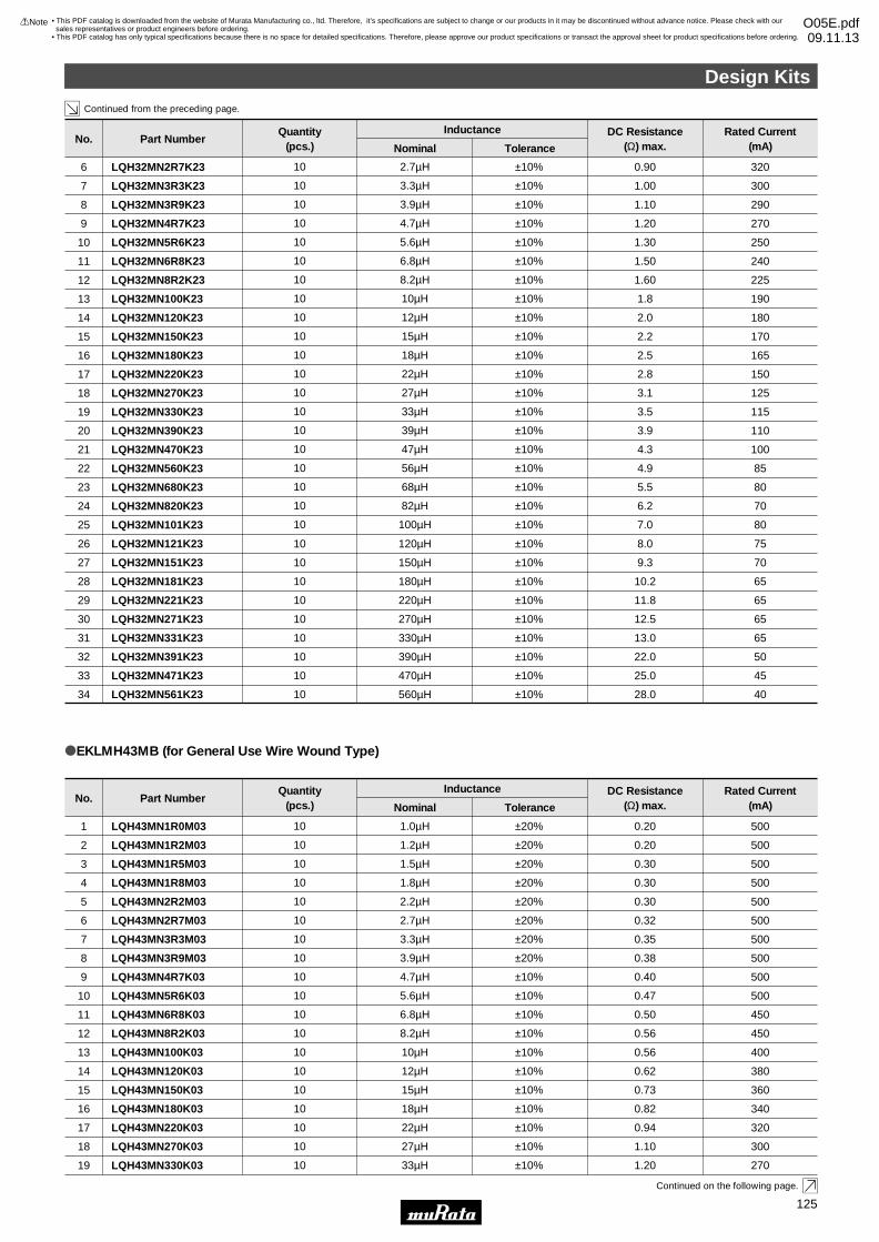
Design Kits
11
Continued from the preceding page.
Continued on the following page.
LQH43MN100K03
LQH43MN120K03
LQH43MN150K03
LQH43MN180K03
LQH43MN220K03
LQH43MN270K03
LQH43MN330K03
13
14
15
16
17
18
19
400
380
360
340
320
300
270
0.56
0.62
0.73
0.82
0.94
1.10
1.20
±10%
±10%
±10%
±10%
±10%
±10%
±10%
10µH
12µH
15µH
18µH
22µH
27µH
33µH
10
10
10
10
10
10
10
oEKLMH43MB (for General Use Wire Wound Type)
Part NumberNo.
LQH43MN1R0M03
LQH43MN1R2M03
LQH43MN1R5M03
LQH43MN1R8M03
LQH43MN2R2M03
LQH43MN2R7M03
LQH43MN3R3M03
LQH43MN3R9M03
LQH43MN4R7K03
LQH43MN5R6K03
LQH43MN6R8K03
LQH43MN8R2K03
1
2
3
4
5
6
7
8
9
10
11
12
Rated Current(mA)
500
500
500
500
500
500
500
500
500
500
450
450
DC Resistance(Ω) max.
0.20
0.20
0.30
0.30
0.30
0.32
0.35
0.38
0.40
0.47
0.50
0.56
ToleranceNominal
±20%
±20%
±20%
±20%
±20%
±20%
±20%
±20%
±10%
±10%
±10%
±10%
Inductance
1.0µH
1.2µH
1.5µH
1.8µH
2.2µH
2.7µH
3.3µH
3.9µH
4.7µH
5.6µH
6.8µH
8.2µH
Quantity(pcs.)
10
10
10
10
10
10
10
10
10
10
10
10
LQH32MN121K23
LQH32MN151K23
LQH32MN181K23
LQH32MN221K23
26
27
28
29
75
70
65
65
8.0
9.3
10.2
11.8
±10%
±10%
±10%
±10%
120µH
150µH
180µH
220µH
10
10
10
10
LQH32MN2R7K23
LQH32MN3R3K23
LQH32MN3R9K23
LQH32MN4R7K23
LQH32MN5R6K23
LQH32MN6R8K23
LQH32MN8R2K23
LQH32MN100K23
LQH32MN120K23
LQH32MN150K23
LQH32MN180K23
LQH32MN220K23
LQH32MN270K23
LQH32MN330K23
LQH32MN390K23
LQH32MN470K23
LQH32MN560K23
LQH32MN680K23
LQH32MN820K23
LQH32MN101K23
6
7
8
9
10
11
12
13
14
15
16
17
18
19
20
21
22
23
24
25
320
300
290
270
250
240
225
190
180
170
165
150
125
115
110
100
85
80
70
80
0.90
1.00
1.10
1.20
1.30
1.50
1.60
1.8
2.0
2.2
2.5
2.8
3.1
3.5
3.9
4.3
4.9
5.5
6.2
7.0
±10%
±10%
±10%
±10%
±10%
±10%
±10%
±10%
±10%
±10%
±10%
±10%
±10%
±10%
±10%
±10%
±10%
±10%
±10%
±10%
2.7µH
3.3µH
3.9µH
4.7µH
5.6µH
6.8µH
8.2µH
10µH
12µH
15µH
18µH
22µH
27µH
33µH
39µH
47µH
56µH
68µH
82µH
100µH
10
10
10
10
10
10
10
10
10
10
10
10
10
10
10
10
10
10
10
10
LQH32MN271K23
LQH32MN331K23
LQH32MN391K23
LQH32MN471K23
LQH32MN561K23
30
31
32
33
34
65
65
50
45
40
12.5
13.0
22.0
25.0
28.0
±10%
±10%
±10%
±10%
±10%
270µH
330µH
390µH
470µH
560µH
10
10
10
10
10
Part NumberNo.Rated Current
(mA)DC Resistance
(Ω) max.ToleranceNominal
InductanceQuantity(pcs.)
Design Kits
!Note • Please read rating and !CAUTION (for storage, operating, rating, soldering, mounting and handling) in this catalog to prevent smoking and/or burning, etc.• This catalog has only typical specifications because there is no space for detailed specifications. Therefore, please approve our product specifications or transact the approval sheet for product specifications before ordering.
125
• This PDF catalog is downloaded from the website of Murata Manufacturing co., ltd. Therefore, it’s specifications are subject to change or our products in it may be discontinued without advance notice. Please check with our sales representatives or product engineers before ordering.
• This PDF catalog has only typical specifications because there is no space for detailed specifications. Therefore, please approve our product specifications or transact the approval sheet for product specifications before ordering.
!Note O05E.pdf09.11.13
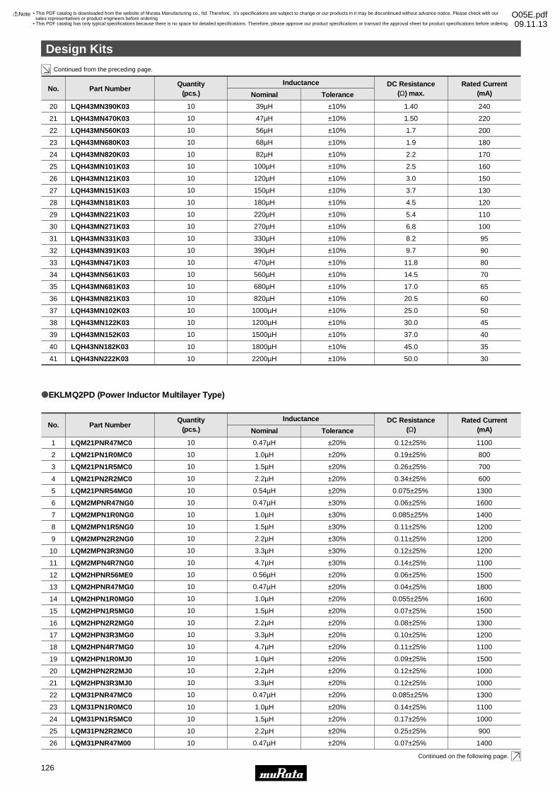
Continued from the preceding page.
12
Design Kits
Continued on the following page.
LQM31PN1R0MC0
LQM31PN1R5MC0
LQM31PN2R2MC0
LQM31PNR47M00
23
24
25
26
1100
1000
900
1400
0.14±25%
0.17±25%
0.25±25%
0.07±25%
±20%
±20%
±20%
±20%
1.0µH
1.5µH
2.2µH
0.47µH
10
10
10
10
oEKLMQ2PD (Power Inductor Multilayer Type)
Part NumberNo.
LQM21PNR47MC0
LQM21PN1R0MC0
LQM21PN1R5MC0
LQM21PN2R2MC0
LQM21PNR54MG0
LQM2MPNR47NG0
LQM2MPN1R0NG0
LQM2MPN1R5NG0
LQM2MPN2R2NG0
LQM2MPN3R3NG0
LQM2MPN4R7NG0
LQM2HPNR56ME0
LQM2HPNR47MG0
LQM2HPN1R0MG0
LQM2HPN1R5MG0
LQM2HPN2R2MG0
LQM2HPN3R3MG0
LQM2HPN4R7MG0
LQM2HPN1R0MJ0
LQM2HPN2R2MJ0
LQM2HPN3R3MJ0
LQM31PNR47MC0
1
2
3
4
5
6
7
8
9
10
11
12
13
14
15
16
17
18
19
20
21
22
Rated Current(mA)
1100
800
700
600
1300
1600
1400
1200
1200
1200
1100
1500
1800
1600
1500
1300
1200
1100
1500
1000
1000
1300
DC Resistance(Ω)
0.12±25%
0.19±25%
0.26±25%
0.34±25%
0.075±25%
0.06±25%
0.085±25%
0.11±25%
0.11±25%
0.12±25%
0.14±25%
0.06±25%
0.04±25%
0.055±25%
0.07±25%
0.08±25%
0.10±25%
0.11±25%
0.09±25%
0.12±25%
0.12±25%
0.085±25%
ToleranceNominal
±20%
±20%
±20%
±20%
±20%
±30%
±30%
±30%
±30%
±30%
±30%
±20%
±20%
±20%
±20%
±20%
±20%
±20%
±20%
±20%
±20%
±20%
Inductance
0.47µH
1.0µH
1.5µH
2.2µH
0.54µH
0.47µH
1.0µH
1.5µH
2.2µH
3.3µH
4.7µH
0.56µH
0.47µH
1.0µH
1.5µH
2.2µH
3.3µH
4.7µH
1.0µH
2.2µH
3.3µH
0.47µH
Quantity(pcs.)
10
10
10
10
10
10
10
10
10
10
10
10
10
10
10
10
10
10
10
10
10
10
LQH43NN182K03
LQH43NN222K03
40
41
35
30
45.0
50.0
±10%
±10%
1800µH
2200µH
10
10
Part NumberNo.Rated Current
(mA)DC Resistance
(Ω) max.ToleranceNominal
InductanceQuantity(pcs.)
LQH43MN390K03
LQH43MN470K03
LQH43MN560K03
LQH43MN680K03
LQH43MN820K03
LQH43MN101K03
LQH43MN121K03
LQH43MN151K03
LQH43MN181K03
LQH43MN221K03
LQH43MN271K03
LQH43MN331K03
LQH43MN391K03
LQH43MN471K03
LQH43MN561K03
LQH43MN681K03
LQH43MN821K03
LQH43MN102K03
LQH43MN122K03
LQH43MN152K03
20
21
22
23
24
25
26
27
28
29
30
31
32
33
34
35
36
37
38
39
240
220
200
180
170
160
150
130
120
110
100
95
90
80
70
65
60
50
45
40
1.40
1.50
1.7
1.9
2.2
2.5
3.0
3.7
4.5
5.4
6.8
8.2
9.7
11.8
14.5
17.0
20.5
25.0
30.0
37.0
±10%
±10%
±10%
±10%
±10%
±10%
±10%
±10%
±10%
±10%
±10%
±10%
±10%
±10%
±10%
±10%
±10%
±10%
±10%
±10%
39µH
47µH
56µH
68µH
82µH
100µH
120µH
150µH
180µH
220µH
270µH
330µH
390µH
470µH
560µH
680µH
820µH
1000µH
1200µH
1500µH
10
10
10
10
10
10
10
10
10
10
10
10
10
10
10
10
10
10
10
10
Design Kits
!Note • Please read rating and !CAUTION (for storage, operating, rating, soldering, mounting and handling) in this catalog to prevent smoking and/or burning, etc.• This catalog has only typical specifications because there is no space for detailed specifications. Therefore, please approve our product specifications or transact the approval sheet for product specifications before ordering.
126
• This PDF catalog is downloaded from the website of Murata Manufacturing co., ltd. Therefore, it’s specifications are subject to change or our products in it may be discontinued without advance notice. Please check with our sales representatives or product engineers before ordering.
• This PDF catalog has only typical specifications because there is no space for detailed specifications. Therefore, please approve our product specifications or transact the approval sheet for product specifications before ordering.
!Note O05E.pdf09.11.13
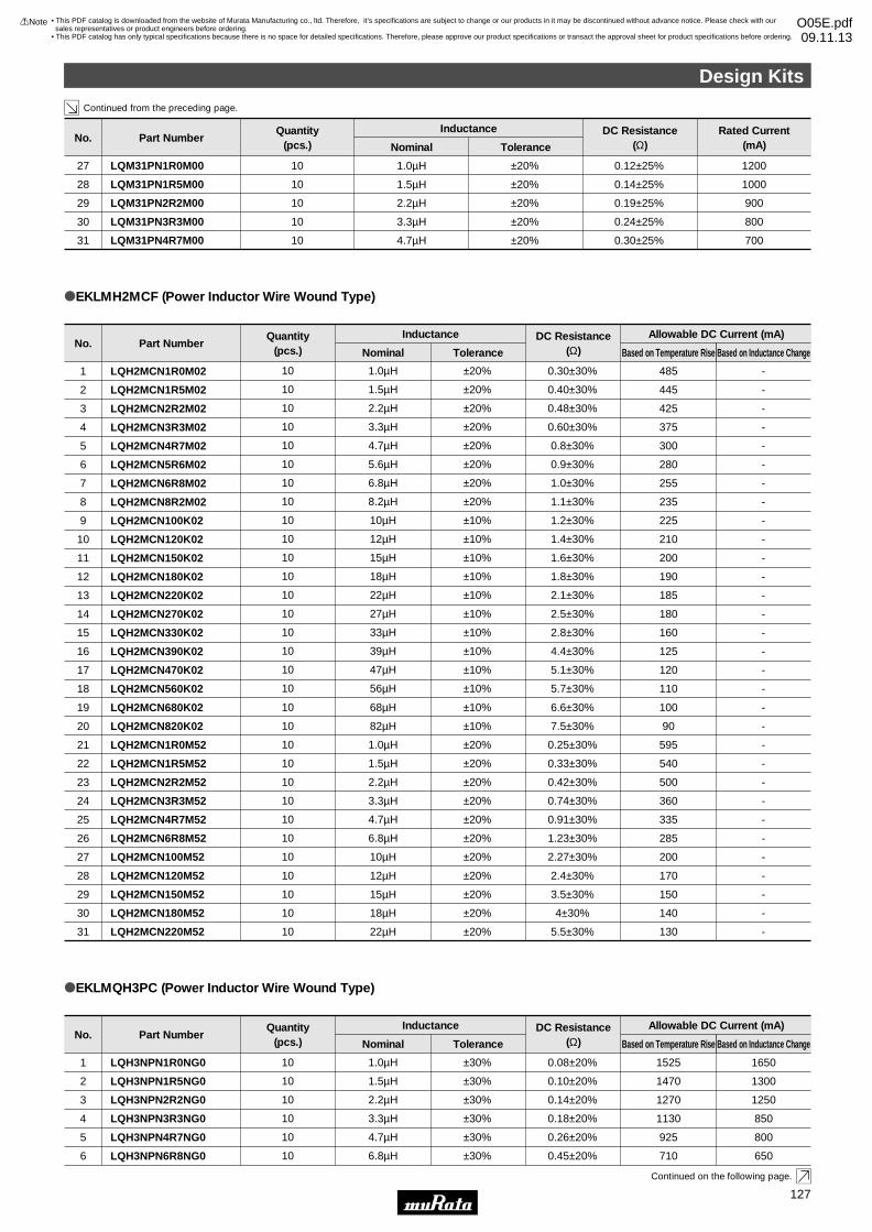
Design Kits
13
Continued from the preceding page.
Continued on the following page.
Part NumberNo.DC Resistance
(Ω)ToleranceNominal
InductanceQuantity(pcs.)
LQH2MCN1R0M02
LQH2MCN1R5M02
LQH2MCN2R2M02
LQH2MCN3R3M02
LQH2MCN4R7M02
LQH2MCN5R6M02
LQH2MCN6R8M02
LQH2MCN8R2M02
LQH2MCN100K02
LQH2MCN120K02
LQH2MCN150K02
LQH2MCN180K02
LQH2MCN220K02
LQH2MCN270K02
LQH2MCN330K02
LQH2MCN390K02
LQH2MCN470K02
LQH2MCN560K02
1
2
3
4
5
6
7
8
9
10
11
12
13
14
15
16
17
18
-
-
-
-
-
-
-
-
-
-
-
-
-
-
-
-
-
-
485
445
425
375
300
280
255
235
225
210
200
190
185
180
160
125
120
110
0.30±30%
0.40±30%
0.48±30%
0.60±30%
0.8±30%
0.9±30%
1.0±30%
1.1±30%
1.2±30%
1.4±30%
1.6±30%
1.8±30%
2.1±30%
2.5±30%
2.8±30%
4.4±30%
5.1±30%
5.7±30%
±20%
±20%
±20%
±20%
±20%
±20%
±20%
±20%
±10%
±10%
±10%
±10%
±10%
±10%
±10%
±10%
±10%
±10%
1.0µH
1.5µH
2.2µH
3.3µH
4.7µH
5.6µH
6.8µH
8.2µH
10µH
12µH
15µH
18µH
22µH
27µH
33µH
39µH
47µH
56µH
10
10
10
10
10
10
10
10
10
10
10
10
10
10
10
10
10
10
oEKLMH2MCF (Power Inductor Wire Wound Type)
Based on Inductance ChangeBased on Temperature Rise
Allowable DC Current (mA)
LQH2MCN680K02
LQH2MCN820K02
LQH2MCN1R0M52
LQH2MCN1R5M52
LQH2MCN2R2M52
LQH2MCN3R3M52
LQH2MCN4R7M52
LQH2MCN6R8M52
LQH2MCN100M52
19
20
21
22
23
24
25
26
27
-
-
-
-
-
-
-
-
-
100
90
595
540
500
360
335
285
200
6.6±30%
7.5±30%
0.25±30%
0.33±30%
0.42±30%
0.74±30%
0.91±30%
1.23±30%
2.27±30%
±10%
±10%
±20%
±20%
±20%
±20%
±20%
±20%
±20%
68µH
82µH
1.0µH
1.5µH
2.2µH
3.3µH
4.7µH
6.8µH
10µH
10
10
10
10
10
10
10
10
10
LQH2MCN120M52
LQH2MCN150M52
LQH2MCN180M52
LQH2MCN220M52
28
29
30
31
-
-
-
-
170
150
140
130
2.4±30%
3.5±30%
4±30%
5.5±30%
±20%
±20%
±20%
±20%
12µH
15µH
18µH
22µH
10
10
10
10
Part NumberNo.DC Resistance
(Ω)ToleranceNominal
InductanceQuantity(pcs.)
LQH3NPN1R0NG0
LQH3NPN1R5NG0
LQH3NPN2R2NG0
LQH3NPN3R3NG0
LQH3NPN4R7NG0
LQH3NPN6R8NG0
1
2
3
4
5
6
1650
1300
1250
850
800
650
1525
1470
1270
1130
925
710
0.08±20%
0.10±20%
0.14±20%
0.18±20%
0.26±20%
0.45±20%
±30%
±30%
±30%
±30%
±30%
±30%
1.0µH
1.5µH
2.2µH
3.3µH
4.7µH
6.8µH
10
10
10
10
10
10
oEKLMQH3PC (Power Inductor Wire Wound Type)
Based on Inductance ChangeBased on Temperature Rise
Allowable DC Current (mA)
Part NumberNo.Rated Current
(mA)DC Resistance
(Ω)ToleranceNominal
InductanceQuantity(pcs.)
LQM31PN1R5M00
LQM31PN2R2M00
LQM31PN3R3M00
LQM31PN4R7M00
28
29
30
31
1000
900
800
700
0.14±25%
0.19±25%
0.24±25%
0.30±25%
±20%
±20%
±20%
±20%
1.5µH
2.2µH
3.3µH
4.7µH
10
10
10
10
LQM31PN1R0M0027 12000.12±25%±20%1.0µH10
Design Kits
!Note • Please read rating and !CAUTION (for storage, operating, rating, soldering, mounting and handling) in this catalog to prevent smoking and/or burning, etc.• This catalog has only typical specifications because there is no space for detailed specifications. Therefore, please approve our product specifications or transact the approval sheet for product specifications before ordering.
127
• This PDF catalog is downloaded from the website of Murata Manufacturing co., ltd. Therefore, it’s specifications are subject to change or our products in it may be discontinued without advance notice. Please check with our sales representatives or product engineers before ordering.
• This PDF catalog has only typical specifications because there is no space for detailed specifications. Therefore, please approve our product specifications or transact the approval sheet for product specifications before ordering.
!Note O05E.pdf09.11.13
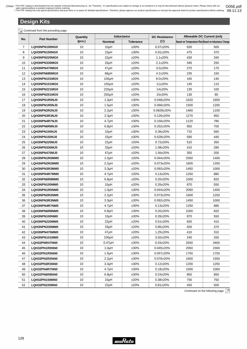
Continued from the preceding page.
14
Design Kits
Continued on the following page.
LQH3NPN1R0NM0
LQH3NPN2R2NM0
LQH3NPN3R3NM0
LQH3NPN4R7NM0
LQH3NPN6R8NM0
LQH3NPN100NM0
LQH3NPN220MM0
LQH3NPN330MM0
LQH3NPN470MM0
LQH3NPN101MM0
LQH32PNR47NN0
LQH32PN1R0NN0
LQH32PN1R5NN0
LQH32PN2R2NN0
LQH32PN3R3NN0
LQH32PN4R7NN0
LQH32PN6R8NN0
LQH32PN100MN0
LQH32PN220MN0
34
35
36
37
38
39
40
41
42
43
44
45
46
47
48
49
50
51
52
1400
1250
1000
880
820
550
410
370
310
200
3400
2300
1750
1550
1250
1000
850
750
500
2050
1600
1450
1250
1000
870
650
500
410
240
2550
2050
1750
1600
1200
1000
850
700
450
0.044±20%
0.073±20%
0.092±20%
0.13±20%
0.20±20%
0.26±20%
0.51±20%
0.85±20%
1.25±20%
3.50±20%
0.03±20%
0.045±20%
0.057±20%
0.076±20%
0.12±20%
0.18±20%
0.24±20%
0.38±20%
0.81±20%
±30%
±30%
±30%
±30%
±30%
±30%
±20%
±20%
±20%
±20%
±30%
±30%
±30%
±30%
±30%
±30%
±30%
±20%
±20%
1.0µH
2.2µH
3.3µH
4.7µH
6.8µH
10µH
22µH
33µH
47µH
100µH
0.47µH
1.0µH
1.5µH
2.2µH
3.3µH
4.7µH
6.8µH
10µH
22µH
10
10
10
10
10
10
10
10
10
10
10
10
10
10
10
10
10
10
10
LQH3NPN680MG0
LQH3NPN101MG0
LQH3NPN151MG0
LQH3NPN221MG0
LQH3NPN251MG0
12
13
14
15
16
150
140
110
100
80
235
165
145
130
130
4.2±20%
8.0±20%
11±20%
14±20%
15±20%
±20%
±20%
±20%
±20%
±20%
68µH
100µH
150µH
220µH
250µH
10
10
10
10
10
LQH3NPN1R0MM0
LQH3NPN2R2MM0
LQH3NPN3R3MM0
LQH3NPN4R7MM0
LQH3NPN6R8MM0
LQH3NPN100MM0
28
29
30
31
32
33
1400
1250
1000
880
820
550
2050
1600
1450
1250
1000
870
0.044±20%
0.073±20%
0.092±20%
0.13±20%
0.20±20%
0.26±20%
±20%
±20%
±20%
±20%
±20%
±20%
1.0µH
2.2µH
3.3µH
4.7µH
6.8µH
10µH
10
10
10
10
10
10
LQH3NPN1R0NJ0
LQH3NPN1R5NJ0
LQH3NPN2R2NJ0
LQH3NPN3R3NJ0
LQH3NPN4R7NJ0
LQH3NPN6R8NJ0
LQH3NPN100NJ0
LQH3NPN150NJ0
LQH3NPN220MJ0
LQH3NPN330MJ0
LQH3NPN470MJ0
17
18
19
20
21
22
23
24
25
26
27
1650
1200
1150
950
780
700
560
440
350
280
200
1620
1500
1460
1270
1120
850
710
590
510
410
350
0.048±20%
0.066±20%
0.0828±20%
0.126±20%
0.156±20%
0.252±20%
0.36±20%
0.528±20%
0.72±20%
1.08±20%
1.56±20%
±30%
±30%
±30%
±30%
±30%
±30%
±30%
±30%
±20%
±20%
±20%
1.0µH
1.5µH
2.2µH
3.3µH
4.7µH
6.8µH
10µH
15µH
22µH
33µH
47µH
10
10
10
10
10
10
10
10
10
10
10
Part NumberNo.DC Resistance
(Ω)ToleranceNominal
InductanceQuantity(pcs.) Based on Inductance ChangeBased on Temperature Rise
Allowable DC Current (mA)
LQH3NPN100NG0
LQH3NPN150NG0
LQH3NPN220MG0
LQH3NPN330MG0
LQH3NPN470MG0
7
8
9
10
11
500
370
340
250
170
630
475
430
345
270
0.57±20%
0.91±20%
1.1±20%
2.1±20%
3.0±20%
±30%
±30%
±20%
±20%
±20%
10µH
15µH
22µH
33µH
47µH
10
10
10
10
10
Design Kits
!Note • Please read rating and !CAUTION (for storage, operating, rating, soldering, mounting and handling) in this catalog to prevent smoking and/or burning, etc.• This catalog has only typical specifications because there is no space for detailed specifications. Therefore, please approve our product specifications or transact the approval sheet for product specifications before ordering.
128
• This PDF catalog is downloaded from the website of Murata Manufacturing co., ltd. Therefore, it’s specifications are subject to change or our products in it may be discontinued without advance notice. Please check with our sales representatives or product engineers before ordering.
• This PDF catalog has only typical specifications because there is no space for detailed specifications. Therefore, please approve our product specifications or transact the approval sheet for product specifications before ordering.
!Note O05E.pdf09.11.13

Design Kits
15
Continued from the preceding page.
Continued on the following page.
LQH32CN4R7M336 6500.15±30%±20%4.7µH10
oEKLMH32CC (Power Inductor Wire Wound Type for Choke)
Part NumberNo.Rated Current
(mA)DC Resistance
(Ω)ToleranceNominal
InductanceQuantity(pcs.)
LQH32CNR15M33
LQH32CNR27M33
LQH32CNR47M33
LQH32CN1R0M33
LQH32CN2R2M33
1
2
3
4
5
1450
1250
1100
1000
790
0.028±30%
0.034±30%
0.042±30%
0.06±30%
0.097±30%
±20%
±20%
±20%
±20%
±20%
0.15µH
0.27µH
0.47µH
1.0µH
2.2µH
10
10
10
10
10
Part NumberNo.
LQM18FN1R0M00
LQM18FN2R2M00
LQM18FN4R7M00
LQM18FN100M00
LQM21FN1R0N00
LQM21FN2R2N00
LQM21FN4R7M70
LQM21FN4R7M80
LQM21FN100M70
LQM21FN100M80
LQM21FN220N00
LQM21FN470N00
LQM31FN100M00
1
2
3
4
5
6
7
8
9
10
11
12
13
Rated Current(mA)
150
120
80
50
220
150
120
120
100
100
13
7
70
DC Resistance(Ω)
0.20±30%
0.40±30%
0.60±30%
0.90±30%
0.20±30%
0.28±30%
0.35±30%
0.18±30%
0.60±30%
0.30±30%
0.35±30%
0.60±30%
0.50 max.
ToleranceNominal
±20%
±20%
±20%
±20%
±30%
±30%
±20%
±20%
±20%
±20%
±30%
±30%
±20%
Inductance
1.0µH
2.2µH
4.7µH
10µH
1.0µH
2.2µH
4.7µH
4.7µH
10µH
10µH
22µH
47µH
10µH
Quantity(pcs.)
10
10
10
10
10
10
10
10
10
10
10
10
10
oEKLMM18FB (Power Inductor Multilayer Type for Choke)
Part NumberNo.DC Resistance
(Ω)ToleranceNominal
InductanceQuantity(pcs.)
LQH55PN1R2NR0
LQH55PN2R2NR0
LQH55PN2R7NR0
LQH55PN3R3NR0
LQH55PN4R7NR0
LQH55PN6R8NR0
LQH55PN100MR0
LQH55PN220MR0
1
2
3
4
5
6
7
8
2600
2100
2070
2000
1400
1200
1000
670
2900
2500
2150
2000
1750
1450
1250
850
0.021±20%
0.031±20%
0.040±20%
0.044±20%
0.060±20%
0.087±20%
0.11±20%
0.26±20%
±30%
±30%
±30%
±30%
±30%
±30%
±20%
±30%
1.2µH
2.2µH
2.7µH
3.3µH
4.7µH
6.8µH
10µH
22µH
10
10
10
10
10
10
10
10
oEKLMQH5PA (Power Inductor Wire Wound Type)
Based on Inductance ChangeBased on Temperature Rise
Allowable DC Current (mA)
Part NumberNo.DC Resistance
(Ω)ToleranceNominal
InductanceQuantity(pcs.)
LQH44PN1R0NP0
LQH44PN2R2MP0
LQH44PN3R3MP0
LQH44PN4R7MP0
LQH44PN6R8MP0
LQH44PN100MP0
LQH44PN220MP0
1
2
3
4
5
6
7
2950
2500
2100
1700
1400
1150
800
2450
1800
1770
1700
1340
1170
790
0.030±20%
0.049±20%
0.065±20%
0.080±20%
0.12±20%
0.16±20%
0.37±20%
±30%
±20%
±20%
±20%
±20%
±20%
±20%
1.0µH
2.2µH
3.3µH
4.7µH
6.8µH
10µH
22µH
10
10
10
10
10
10
10
oEKLMQH4PA (Power Inductor Wire Wound Type)
Based on Inductance ChangeBased on Temperature Rise
Allowable DC Current (mA)
Design Kits
!Note • Please read rating and !CAUTION (for storage, operating, rating, soldering, mounting and handling) in this catalog to prevent smoking and/or burning, etc.• This catalog has only typical specifications because there is no space for detailed specifications. Therefore, please approve our product specifications or transact the approval sheet for product specifications before ordering.
129
• This PDF catalog is downloaded from the website of Murata Manufacturing co., ltd. Therefore, it’s specifications are subject to change or our products in it may be discontinued without advance notice. Please check with our sales representatives or product engineers before ordering.
• This PDF catalog has only typical specifications because there is no space for detailed specifications. Therefore, please approve our product specifications or transact the approval sheet for product specifications before ordering.
!Note O05E.pdf09.11.13
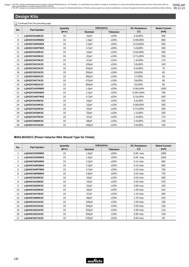
Continued from the preceding page.
16
Design Kits
oEKLMH43CC (Power Inductor Wire Wound Type for Choke)
Part NumberNo.Rated Current
(mA)DC Resistance
(Ω)ToleranceNominal
InductanceQuantity(pcs.)
LQH43CN1R0M03
LQH43CN1R5M03
LQH43CN2R2M03
LQH43CN3R3M03
LQH43CN4R7M03
LQH43CN6R8M03
LQH43CN100K03
LQH43CN150K03
LQH43CN220K03
LQH43CN330K03
LQH43CN470K03
LQH43CN680K03
LQH43CN101K03
LQH43CN151K03
LQH43CN221K03
LQH43CN331K03
LQH43CN471K03
1
2
3
4
5
6
7
8
9
10
11
12
13
14
15
16
17
1080
1000
900
800
750
720
650
570
420
310
280
220
190
130
110
100
90
0.08 max
0.09 max
0.11 max
0.13 max
0.15 max
0.20 max
0.24 max
0.32 max
0.60 max
1.00 max
1.10 max
1.70 max
2.20 max
3.50 max
4.00 max
6.80 max
8.50 max
±20%
±20%
±20%
±20%
±20%
±20%
±10%
±10%
±10%
±10%
±10%
±10%
±10%
±10%
±10%
±10%
±10%
1.0µH
1.5µH
2.2µH
3.3µH
4.7µH
6.8µH
10µH
15µH
22µH
33µH
47µH
68µH
100µH
150µH
220µH
330µH
470µH
10
10
10
10
10
10
10
10
10
10
10
10
10
10
10
10
10
LQH32CN100K53
LQH32CN150K53
LQH32CN220K53
LQH32CN330K53
LQH32CN470K53
LQH32CN680K53
LQH32CN101K53
23
24
25
26
27
28
29
450
300
250
200
170
130
100
0.3±30%
0.58±30%
0.71±30%
1.1±30%
1.3±30%
2.2±30%
3.5±30%
±10%
±10%
±10%
±10%
±10%
±10%
±10%
10µH
15µH
22µH
33µH
47µH
68µH
100µH
10
10
10
10
10
10
10
LQH32CN100K33
LQH32CN1R0M23
LQH32CN2R2M23
LQH32CN4R7M23
LQH32CN100K23
LQH32CN220K23
7
8
9
10
11
12
450
800
600
450
300
250
0.3±30%
0.09±30%
0.13±30%
0.2±30%
0.44±30%
0.71±30%
±10%
±20%
±20%
±20%
±10%
±10%
10µH
1.0µH
2.2µH
4.7µH
10µH
22µH
10
10
10
10
10
10
LQH32CN1R0M53
LQH32CN2R2M53
LQH32CN4R7M53
20
21
22
1000
790
650
0.06±30%
0.097±30%
0.15±30%
±20%
±20%
±20%
1.0µH
2.2µH
4.7µH
10
10
10
LQH32CN331K23
LQH32CN391K23
LQH32CN471K23
LQH32CN561K23
16
17
18
19
60
60
60
60
10±30%
17±30%
19±30%
22±30%
±10%
±10%
±10%
±10%
330µH
390µH
470µH
560µH
10
10
10
10
LQH32CN470K23
LQH32CN101K23
LQH32CN221K23
13
14
15
170
100
70
1.3±30%
3.5±30%
8.4±30%
±10%
±10%
±10%
47µH
100µH
220µH
10
10
10
Part NumberNo.Rated Current
(mA)DC Resistance
(Ω)ToleranceNominal
InductanceQuantity(pcs.)
Design Kits
!Note • Please read rating and !CAUTION (for storage, operating, rating, soldering, mounting and handling) in this catalog to prevent smoking and/or burning, etc.• This catalog has only typical specifications because there is no space for detailed specifications. Therefore, please approve our product specifications or transact the approval sheet for product specifications before ordering.
130
• This PDF catalog is downloaded from the website of Murata Manufacturing co., ltd. Therefore, it’s specifications are subject to change or our products in it may be discontinued without advance notice. Please check with our sales representatives or product engineers before ordering.
• This PDF catalog has only typical specifications because there is no space for detailed specifications. Therefore, please approve our product specifications or transact the approval sheet for product specifications before ordering.
!Note O05E.pdf09.11.13
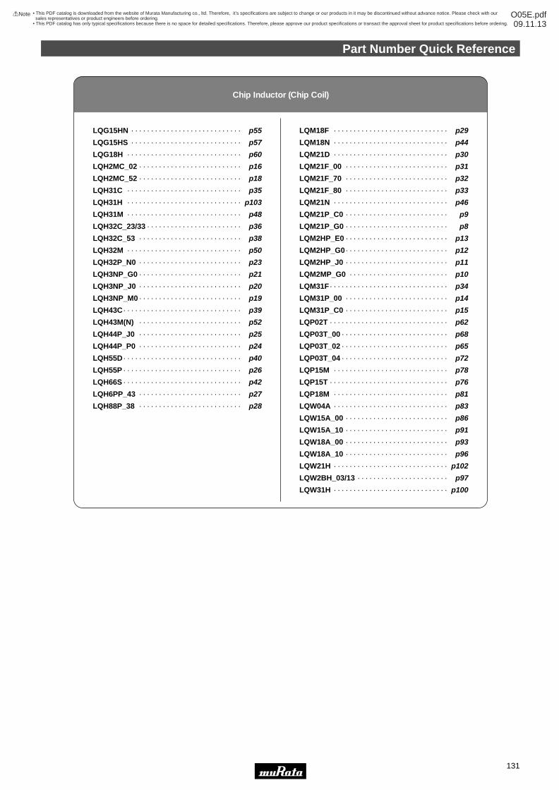
Part Number Quick Reference
!Note • Please read rating and !CAUTION (for storage, operating, rating, soldering, mounting and handling) in this catalog to prevent smoking and/or burning, etc.• This catalog has only typical specifications because there is no space for detailed specifications. Therefore, please approve our product specifications or transact the approval sheet for product specifications before ordering.
131
Chip Inductor (Chip Coil)
LQG15HN
LQG15HS
LQG18H
LQH2MC_02
LQH2MC_52
LQH31C
LQH31H
LQH31M
LQH32C_23/33
LQH32C_53
LQH32M
LQH32P_N0
LQH3NP_G0
LQH3NP_J0
LQH3NP_M0
LQH43C
LQH43M(N)
LQH44P_J0
LQH44P_P0
LQH55D
LQH55P
LQH66S
LQH6PP_43
LQH88P_38
p55
p57
p60
p16
p18
p35
p103
p48
p36
p38
p50
p23
p21
p20
p19
p39
p52
p25
p24
p40
p26
p42
p27
p28
· · · · · · · · · · · · · · · · · · · · · · · · · · · ·
· · · · · · · · · · · · · · · · · · · · · · · · · · · ·
· · · · · · · · · · · · · · · · · · · · · · · · · · · · ·
· · · · · · · · · · · · · · · · · · · · · · · · · ·
· · · · · · · · · · · · · · · · · · · · · · · · · ·
· · · · · · · · · · · · · · · · · · · · · · · · · · · · ·
· · · · · · · · · · · · · · · · · · · · · · · · · · · · ·
· · · · · · · · · · · · · · · · · · · · · · · · · · · · ·
· · · · · · · · · · · · · · · · · · · · · · · ·
· · · · · · · · · · · · · · · · · · · · · · · · · ·
· · · · · · · · · · · · · · · · · · · · · · · · · · · · ·
· · · · · · · · · · · · · · · · · · · · · · · · · ·
· · · · · · · · · · · · · · · · · · · · · · · · · ·
· · · · · · · · · · · · · · · · · · · · · · · · · ·
· · · · · · · · · · · · · · · · · · · · · · · · · ·
· · · · · · · · · · · · · · · · · · · · · · · · · · · · · ·
· · · · · · · · · · · · · · · · · · · · · · · · · ·
· · · · · · · · · · · · · · · · · · · · · · · · · ·
· · · · · · · · · · · · · · · · · · · · · · · · · ·
· · · · · · · · · · · · · · · · · · · · · · · · · · · · · ·
· · · · · · · · · · · · · · · · · · · · · · · · · · · · · ·
· · · · · · · · · · · · · · · · · · · · · · · · · · · · · ·
· · · · · · · · · · · · · · · · · · · · · · · · · ·
· · · · · · · · · · · · · · · · · · · · · · · · · ·
LQM18F
LQM18N
LQM21D
LQM21F_00
LQM21F_70
LQM21F_80
LQM21N
LQM21P_C0
LQM21P_G0
LQM2HP_E0
LQM2HP_G0
LQM2HP_J0
LQM2MP_G0
LQM31F
LQM31P_00
LQM31P_C0
LQP02T
LQP03T_00
LQP03T_02
LQP03T_04
LQP15M
LQP15T
LQP18M
LQW04A
LQW15A_00
LQW15A_10
LQW18A_00
LQW18A_10
LQW21H
LQW2BH_03/13
LQW31H
p29
p44
p30
p31
p32
p33
p46
p9
p8
p13
p12
p11
p10
p34
p14
p15
p62
p68
p65
p72
p78
p76
p81
p83
p86
p91
p93
p96
p102
p97
p100
· · · · · · · · · · · · · · · · · · · · · · · · · · · · ·
· · · · · · · · · · · · · · · · · · · · · · · · · · · · ·
· · · · · · · · · · · · · · · · · · · · · · · · · · · · ·
· · · · · · · · · · · · · · · · · · · · · · · · · ·
· · · · · · · · · · · · · · · · · · · · · · · · · ·
· · · · · · · · · · · · · · · · · · · · · · · · · ·
· · · · · · · · · · · · · · · · · · · · · · · · · · · · ·
· · · · · · · · · · · · · · · · · · · · · · · · · ·
· · · · · · · · · · · · · · · · · · · · · · · · · ·
· · · · · · · · · · · · · · · · · · · · · · · · · ·
· · · · · · · · · · · · · · · · · · · · · · · · · ·
· · · · · · · · · · · · · · · · · · · · · · · · · ·
· · · · · · · · · · · · · · · · · · · · · · · · ·
· · · · · · · · · · · · · · · · · · · · · · · · · · · · · ·
· · · · · · · · · · · · · · · · · · · · · · · · · ·
· · · · · · · · · · · · · · · · · · · · · · · · · ·
· · · · · · · · · · · · · · · · · · · · · · · · · · · · · ·
· · · · · · · · · · · · · · · · · · · · · · · · · · ·
· · · · · · · · · · · · · · · · · · · · · · · · · · ·
· · · · · · · · · · · · · · · · · · · · · · · · · · ·
· · · · · · · · · · · · · · · · · · · · · · · · · · · · ·
· · · · · · · · · · · · · · · · · · · · · · · · · · · · · ·
· · · · · · · · · · · · · · · · · · · · · · · · · · · · ·
· · · · · · · · · · · · · · · · · · · · · · · · · · · · ·
· · · · · · · · · · · · · · · · · · · · · · · · · ·
· · · · · · · · · · · · · · · · · · · · · · · · · ·
· · · · · · · · · · · · · · · · · · · · · · · · · ·
· · · · · · · · · · · · · · · · · · · · · · · · · ·
· · · · · · · · · · · · · · · · · · · · · · · · · · · · ·
· · · · · · · · · · · · · · · · · · · · · · ·
· · · · · · · · · · · · · · · · · · · · · · · · · · · · ·
• This PDF catalog is downloaded from the website of Murata Manufacturing co., ltd. Therefore, it’s specifications are subject to change or our products in it may be discontinued without advance notice. Please check with our sales representatives or product engineers before ordering.
• This PDF catalog has only typical specifications because there is no space for detailed specifications. Therefore, please approve our product specifications or transact the approval sheet for product specifications before ordering.
!Note O05E.pdf09.11.13
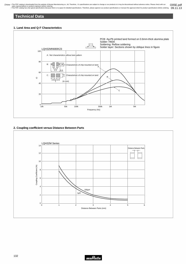
1. Land Area and Q-F Characteristics
2. Coupling coefficient versus Distance Between Parts
14
10
12
8
6
4
0
2
10 2 3
Distance Between Parts (mm)
Cou
plin
g C
oeffi
cien
t (%
)
4 5 6
1µH
330µH
Distance Between Parts
100
80
60
40
20
050k10k 100k 500k
Frequency (Hz)
Q
1M 5M
A
B
C
2.5 2.5
2.5
21
1
1 15.51.3
(in mm)
C :
B : Characteristic of chip mounted on land
Characteristic of chip mounted on land
A : Net characteristics without land pattern
PCB: Ag-Pb printed land formed on 0.6mm-thick alumina plateSolder: H60ASoldering: Reflow solderingSolder layer: Sections shown by oblique lines in figure
LQH32MN680K23
LQH32M Series
Technical Data
!Note • Please read rating and !CAUTION (for storage, operating, rating, soldering, mounting and handling) in this catalog to prevent smoking and/or burning, etc.• This catalog has only typical specifications because there is no space for detailed specifications. Therefore, please approve our product specifications or transact the approval sheet for product specifications before ordering.
132
• This PDF catalog is downloaded from the website of Murata Manufacturing co., ltd. Therefore, it’s specifications are subject to change or our products in it may be discontinued without advance notice. Please check with our sales representatives or product engineers before ordering.
• This PDF catalog has only typical specifications because there is no space for detailed specifications. Therefore, please approve our product specifications or transact the approval sheet for product specifications before ordering.
!Note O05E.pdf09.11.13
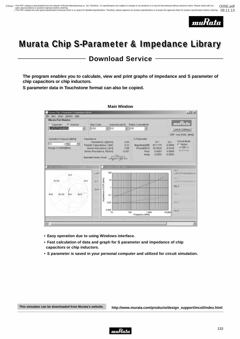
Murata Chip S-Parameter & Impedance Library
• Easy operation due to using Windows interface.
• Fast calculation of data and graph for S parameter and impedance of chip capacitors or chip inductors.
• S parameter is saved in your personal computer and utilized for circuit simulation.
The program enables you to calculate, view and print graphs of impedance and S parameter of chip capacitors or chip inductors.S parameter data in Touchstone format can also be copied.
Murata Chip S-Parameter & Impedance LibraryDownload Service
Main Window
http://www.murata.com/products/design_support/mcsil/index.htmlThis simulator can be downloaded from Murata's website.
133
• This PDF catalog is downloaded from the website of Murata Manufacturing co., ltd. Therefore, it’s specifications are subject to change or our products in it may be discontinued without advance notice. Please check with our sales representatives or product engineers before ordering.
• This PDF catalog has only typical specifications because there is no space for detailed specifications. Therefore, please approve our product specifications or transact the approval sheet for product specifications before ordering.
!Note O05E.pdf09.11.13