Coil-EEFL Tubes as Unrivaled Light Source with Small W ...
10
Science Research 2015; 3(4): 230-239 Published online August 5, 2015 (http://www.sciencepublishinggroup.com/j/sr) doi: 10.11648/j.sr.20150304.21 ISSN: 2329-0935 (Print); ISSN: 2329-0927 (Online) Coil-EEFL Tubes as Unrivaled Light Source with Small W coil Over Solid Light Sources Lyuji Ozawa Japanese Government licensed Consultant in Science, Changping Qu, Beijing, China Email address: [email protected] To cite this article: Lyuji Ozawa. Coil-EEFL Tubes as Unrivaled Light Source with Small W coil Over Solid Light Sources. Science Research. Vol. 3, No. 4, 2015, pp. 230-239. doi: 10.11648/j.sr.20150304.21 Abstract: It has found that the active power consumption, W coil , of the single coil-EEFL tube that is not related with the energy for the generation of the lights, reduces to below 0.1 W act of the commercial CCFL tube with the same brightness of the original CCFL tube. The coil-EEFL tubes allow the parallel connection with the single external AC driving circuit. ΣW coil of 10 coil-EEFL tubes goes down to 0.03 ΣW act . The figure of the merit of the lighting devices is quantum efficiency η q . The η q of the FL tubes is the astronomical number that is 10 13 visible photons per unit volume (m 3 ) of Ar gas space per unit time (s) by one moving electron in the superconductive vacuum. The coil-EEFL tubes hold the unrivaled advantage with the power consumption and illuminance (lm m -2 ) over the solid LED lamps that have only η q ≈ 0.5. A half of the injected electrons inevitably lose the energy by the Joule Heat. Keywords: Green Energy, Power Consumption, Light Source, FL Tube, PDP 1. Introduction The FL tubes have the studied for more than 80 years. The established technologies of the FL tubes however conceal the great latent advantages of the lighted FL tubes by the invalided evaluations and misinterpretations of the observed results. The latent advantages of FL tubes are below: 1. The coexistence of the disparate electric circuits [1, 2]. They are (a) the external AC driving circuit and (b) the internal DC electric circuit, notwithstanding the FL tube is operated with the visible AC driving circuit. The internal DC electric circuit in Ar as space is invisible by the naked eyes, so that the presence has overlooked in the past study. Then, it has believed for 80 years that the lights in the FL tubes generate by the electrons from the external AC driving circuit [3, 4, 5, 6]. Recently it has revealed that the electrodes of the HCFL tubes never emit the thermoelectrons into the Ar gas space [7]. Consequently, the electrons in the external AC driving circuit never emit the light. The moving electrons from the cathode and anode of the internal DC electric power generator solely generate the lights from FL tubes. 2. The lights from the FL tubes generate from the excitation of Hg atoms by the moving electrons in the “superconductive vacuum between Ar atoms” in lighted FL tube [8]. The moving electrons in the superconductive vacuum do not lose the kinetic energy. Statistically, one moving electron in the lighted FL tube generates the astronomical number of 10 13 visible photons per unit volume of Ar gas space (m 3 ) per unit time (s) that is the quantum efficiency η q [8]. The figure of the merit of the lighting devices is the η q . In the past, the study of the FL tubes, including PDP, ever reported η q . 3. The commercial compact 20W-HCFL tube, that the positive column has the temperature at 60 o C, emits the illuminance of 5700 (lm m -2 ) [9], corresponding to “2 x 10 26 photons per second”. The compact 20W-HCFL tube comfortably illuminate the furniture or desktop in 17 m 2 room with the daytime scenery under the slightly overcastting sky, which the human eyes adjust for 5 million years. The comfortable illumination of the room is made by the illuminance (330 lm m -2 ). The required number of the FL tubes for the illumination of the given room has ever calculated quantitatively, The illuminated room by one compact 20W-HCFL tube is calculated as 17 m 2 {5700 (lm m -2 ) x (330 lm) -1 }. Many commercial compact HCFL tubes do not light up with the illuminance of 5700 (lm m -2 ). They are around 2000 (lm m -2 ) with misunderstanding of the evaluation of the performance of the FL tubes by the luminous efficiency (lm W -1 ).
Transcript of Coil-EEFL Tubes as Unrivaled Light Source with Small W ...

Science Research 2015; 3(4): 230-239
Published online August 5, 2015 (http://www.sciencepublishinggroup.com/j/sr)
doi: 10.11648/j.sr.20150304.21
ISSN: 2329-0935 (Print); ISSN: 2329-0927 (Online)
Coil-EEFL Tubes as Unrivaled Light Source with Small Wcoil Over Solid Light Sources
Lyuji Ozawa
Japanese Government licensed Consultant in Science, Changping Qu, Beijing, China
Email address: [email protected]
To cite this article: Lyuji Ozawa. Coil-EEFL Tubes as Unrivaled Light Source with Small Wcoil Over Solid Light Sources. Science Research.
Vol. 3, No. 4, 2015, pp. 230-239. doi: 10.11648/j.sr.20150304.21
Abstract: It has found that the active power consumption, Wcoil, of the single coil-EEFL tube that is not related with the energy
for the generation of the lights, reduces to below 0.1 Wact of the commercial CCFL tube with the same brightness of the original
CCFL tube. The coil-EEFL tubes allow the parallel connection with the single external AC driving circuit. ΣWcoil of 10
coil-EEFL tubes goes down to 0.03 ΣWact. The figure of the merit of the lighting devices is quantum efficiency ηq. The ηq of the
FL tubes is the astronomical number that is 1013
visible photons per unit volume (m3) of Ar gas space per unit time (s) by one
moving electron in the superconductive vacuum. The coil-EEFL tubes hold the unrivaled advantage with the power consumption
and illuminance (lm m-2
) over the solid LED lamps that have only ηq ≈ 0.5. A half of the injected electrons inevitably lose the
energy by the Joule Heat.
Keywords: Green Energy, Power Consumption, Light Source, FL Tube, PDP
1. Introduction
The FL tubes have the studied for more than 80 years. The
established technologies of the FL tubes however conceal the
great latent advantages of the lighted FL tubes by the invalided
evaluations and misinterpretations of the observed results. The
latent advantages of FL tubes are below:
1. The coexistence of the disparate electric circuits [1, 2].
They are (a) the external AC driving circuit and (b) the
internal DC electric circuit, notwithstanding the FL tube
is operated with the visible AC driving circuit. The
internal DC electric circuit in Ar as space is invisible by
the naked eyes, so that the presence has overlooked in
the past study. Then, it has believed for 80 years that the
lights in the FL tubes generate by the electrons from the
external AC driving circuit [3, 4, 5, 6]. Recently it has
revealed that the electrodes of the HCFL tubes never
emit the thermoelectrons into the Ar gas space [7].
Consequently, the electrons in the external AC driving
circuit never emit the light. The moving electrons from
the cathode and anode of the internal DC electric power
generator solely generate the lights from FL tubes.
2. The lights from the FL tubes generate from the excitation
of Hg atoms by the moving electrons in the
“superconductive vacuum between Ar atoms” in lighted
FL tube [8]. The moving electrons in the superconductive
vacuum do not lose the kinetic energy. Statistically, one
moving electron in the lighted FL tube generates the
astronomical number of 1013
visible photons per unit
volume of Ar gas space (m3) per unit time (s) that is the
quantum efficiency ηq [8]. The figure of the merit of the
lighting devices is the ηq. In the past, the study of the FL
tubes, including PDP, ever reported ηq.
3. The commercial compact 20W-HCFL tube, that the
positive column has the temperature at 60oC, emits the
illuminance of 5700 (lm m-2
) [9], corresponding to “2 x
1026
photons per second”. The compact 20W-HCFL
tube comfortably illuminate the furniture or desktop in
17 m2 room with the daytime scenery under the slightly
overcastting sky, which the human eyes adjust for 5
million years. The comfortable illumination of the room
is made by the illuminance (330 lm m-2
). The required
number of the FL tubes for the illumination of the given
room has ever calculated quantitatively, The illuminated
room by one compact 20W-HCFL tube is calculated as
17 m2 {5700 (lm m
-2) x (330 lm)
-1}. Many commercial
compact HCFL tubes do not light up with the
illuminance of 5700 (lm m-2
). They are around 2000 (lm
m-2
) with misunderstanding of the evaluation of the
performance of the FL tubes by the luminous efficiency
(lm W-1
).

Science Research 2015; 3(4): 230-239 231
4. Incorrect determination of the commercial FL tubes.
The real active power consumption, Wact, of the external
AC driving circuit has deliberately determined with the
Wtube, neglected Wdrive [10]. The actual Wact of the
external AC driving device is given by Wact = Wtube +
Wdrive. The Wact of the 40W-HCFL tube is around 80 W
with the ballast (chock coil) and 60 W with the inverter.
5. The antipollution of Hg on the earth by the scrapped FL
tubes. The Hg atoms in FL tubes are liquid Hg. The real
Hg pollution to the living life is made with the organic
Hg compounds. Anyhow, the operation life of the FL
tubes prolongs to longer than 105 hours by the
application of the coil-EEFL tubes. If one uses the lamp
for 10 hours per day, he may light up the lamp for 4 x
103 hours per year, and 4 x 10
4 hours for 10 years. If one
takes the HCFL tubes, the operation life is less than 104
hours with the evaporation of the W-filament coil.
Those are the example of concealed latent advantages of the
lighted FL tubes by the determination by the erroneous
luminous efficiency (lm W-1
). The luminance from the lighted
FL tubes is significantly influenced by the electric field, Fphos,
from the electric charges on the phosphor screen [10].
At present, the LED lamps are on the market with the
advertisement of the energy saving light source. We may
calculate, as an example, the illumination of the room by the
LED lamps as the scientific reality. The lighting mechanisms
of the LED lamps quite differ from the FL tubes. The LED
lamp emits a photon by the recombination of a pair of the
electron and hole at the luminescence center. The number of
the recombinations of the electrons and holes determines the
number of the lighted photons. The number of the photons
does not change with the applied voltage to the LED. For the
generation of the lights by the LED lamp, the electrons and
holes must inject into the LED lamp. The LED lamp is the
solid device that is not the superconductive device. The LED
lamps inevitable have the electric resistance so that the
injected electrons and holes in the LED lamp lose some
amount of the energy by the electric resistance as the Joule
Heat. The experimentally determined quantum efficiency is ηq
≈ 0.5 [11]. Two (2) pairs of the electrons and holes must inject
to the LED lamp for the generation of one photon. We may
calculate the number of the injected electrons into the LED
lamp for the illumination of the 1 m2 room. The calculated
number is 2 x 1025
electrons per second to the LED lamp on
the dais. The 2 x 1025
electrons per second correspond to the
DC electric current of 3 x 10⁶ A = 3 x 10
3 kA (= 1.6 x 10
-19 x 2
x 1025
Coulomb per second). The LEDs are solids that
inevitably have the electric resistance caused by the thermal
perturbation from the thermally vibrating atoms at the lattice
sites. The thermally perturbed energy level becomes the bands.
You may detect the absorption bands by the spectrometer. The
generated Joule Heat in the LED lamps is given by I2R. The
LED lamps are operated with the low applied voltage, 2,8V,
but with the huge electric current 3 x 10⁶ A. The power
consumption is calculated as 8.4 x 10³ kW (= 2.8 V x 3 x 10
6
A). If the LED lamps operated with field scan [12], the power
consumption of the LED alone may reduce to the 1.2 kW (=
8.4 x 106 x 1.5 x 10
-4 W) by the field scan for the illumination
of the 1 m2 room. As already described, one compact
20W-HCFL tube may illuminate the 17 m2 room with the
illuminance (330 lm m-2
). If the same room is illuminated by
the LED lamps, the required LED lamps are calculated as 17
times of the LED lamps on the dais. The LED lamps are the
heater of 20 kW (= 1.2 x 17 kW) for the illumination by the
illuminance (330 lm m-2
). The field scan of the LED lamps
requires the AC driving circuit. There is no theoretical
calculation data based on the ηq. There is a large difference
between the commercial advisement and science. Total power
consumption of the LED lamps with the field scan adds the
Wdrive of the AC driving circuit. The theoretical and
quantitative calculations indicate that the practical LED lamps
for the illumination purpose inevitably radiate the huge
amount of the heat in the illuminating room. You may
compare with the commercialized compact 20W-HCFL tube.
The advantage of the commercialized compact 20W-HCFL
tube has been concealed with the erroneous luminous
efficiency (lm W-1
).
The above quantitative calculations clearly indicate that the
lighted FL tubes hold the great latent advantage as the
unrivaled light source as if the removal or significantly
reduction of the unnecessary Wact of the external AC driving
circuit is made for the lighting source on the given room. For
instance, the power consumption of the internal DC electric
power generator of the nominal 40W-HCFL tube is below 0.1
W. The active AC power consumption, Wact, of the external
AC power consumption is 60 W. In this report, we will take a
first priority that is the reduction of the unnecessary Wact for
the light generation of the FL tubes. The Wact may down to a
few % levels from the present Wact by the application of the
coil-EEFL tubes [2]. As the reduced Wcoil to a few % of the
present Wact, the coil-EEFL tubes may operate with the
combination of the solar cells and battery. The remarkable
reduction of the Wact really contributes to the green energy
project on the world.
2. Significant Reduction of Wact by
Application of Coil-EEFL Tubes
The urgent subject for the improvement of the FL tubes is
the significant reduction of the Wact of the external AC driving
circuit with the long operation life. We cannot take the
commercial HCFL tubes for the study on the reduction of the
Wact. The HCFL tubes essentially have the large Wact and short
operation life less than 103 hours. The large Wact is caused by
the large induced AC current in the external AC driving circuit.
The large induced AC current comes from the large
capacitance of the Ctube that is formed with the large number of
the Ar1+
in the lighted FL tube. The unnecessary Wact for the
lighting of the FL tubes is determined by the large induced AC
current from the capacitor Ctube. It has found that the Wact of
the single lighted HCFL tubes may reduce to 0.1 Wact of the
present FL tube by the conversion to the coil-EEFL tube. Then,
we have found the further reduction of the Wcoil to 0.03 Wact by

232 Lyuji Ozawa: Coil-EEFL Tubes as Unrivaled Light Source with Small Wcoil Over Solid Light Sources
the parallel connection of 10 coil-EEFL tubes with the single
AC driving circuit that has the transformer for the output
voltage. The designers of the AC and DC driving circuits of
the coil-EEFL tubes may contribute to the remarkable
reduction of the ΣWcoil. The details are below:
2.1. No Involvement of Ctube in AC Operation of Coil-EEFL
Tubes
The ordinal FL tubes have the disadvantage that the
electrodes of the FL tube pick up the large induced AC current
from the huge number of the Ar1+
in the Ar gas space of the
lighted FL tubes. The number of the Ar1+
in the Ar gas space
changes with the Ar gas pressures at the given FL tube. The
number of Ar1+
changes with the diameters and length of the
FL tube at the given Ar gas pressure. The large induced AC
current results in the large Wact of the external AC driving
circuit. The size and Ar gas pressures of the commercial
HCFL tubes have been determined by the minimization of the
Wact.
It has found that the external electrodes (EEs) of the AC
driving circuit of the lighted coil-EEFL tubes do not pick up
the induced AC current from the Ctube. The operation
conditions of the coil-EEFL tubes are free from the amount of
the Ar1+
in the lighted FL tube. This is a breakthrough of the
study on the FL tubes. The coil-EEFL tubes may contain the
high Ar gas pressures without the change of the Wcoil. The
facts described above allow us that the study on the details of
the Wcoil of the coil-EEFL tubes can be made with the
coil-EEFL tubes by the conversion from the commercial FL
tubes. The results may apply to the Wcoil of the coil-EEFL
tubes that have improved the illuminance with the high Ar gas
pressure; e. g., 1 x10⁴ Pa (= 70 Torr) without change of the
Wcoil.
It is well known that the illuminance (lm m-2
) of the FL
tubes linearly increases with the Ar gas pressures, but the Wact
of the external AC driving circuit also linearly increases with
the Ar gas pressures. The coil-EEFL tubes can be operated
with the high Ar gas pressures, e.g., 104 Pa (= 70 Torr) without
change the Wcoil. Therefore, the coil-EEFL tubes may operate
the high Ar gas pressures with the same Wcoil, resulting in the
high illuminance (lm m-2
) with the same Wcoil, as if the
coil-EEFL tubes have the shallow gap less than 3 x 10⁻⁴
m
[10].
The coil-EEFL tubes exclusively utilize the cathode and
anode of the internal DC electric power generator that forms in
the Ar gas space without the injection of the electrons from the
external AC driving circuit [2]. The real cathode and anode for
the operation of the lighted FL tubes are the volume of the
glow lights on the polarized phosphor particles under the EEs
on the outer glass wall of the FL tubes [2].
The thickness of the volume of the glow light on the
polarized phosphor particles is around 3 x 10⁻³
m on the
polarized phosphor particles under the EEs. The thickness of
the glow lights on the polarized phosphor particles determines
the preferable diameters of the coil-EEFL tubes. The total
thickness of the volume of the glow lights in the given FL tube
is 6 x 10⁻³
m (= 2 x 3 x 10-3
m). The total thickness of the glass
tube is 2 x 10⁻³
m. The preferable outer diameters of the
coil-EEFL tubes are calculated as 8 x 10⁻³
m {= (6 + 2) x 10-3
m}. Practically the outer diameter of the coil-EEFL tubes is
narrower than 1.2 x 10⁻²
m (T-4) for the high illuminance (lm
m-2
) with the high Ar gas pressures. The coil-EEFL tube wider
than 1.2 x 10⁻²
m also emits the illuminance (lm m-2
) higher
than that of the commercial HCFL tubes with the high Ar gas
pressures. The coil-EEFL tubes with the wider glass tubes
require the high Ar gas pressures, preferably 1 x 10⁴ Pa (= 70
Torr), for the increase in the scattering of the moving electrons
in the wide positive column for the generation of the lights.
Unfortunately, we do not have the proper production facilities
for the coil-EEFL tubes in China. With this reason, we take the
commercial CCFL tubes produced by other countries for the
study on the coil-EEFL tubes.
The coil-EEFL tubes have produced by the conversion from
the commercial CCFL tube in the outer diameter of 9.5 x 10⁻²
m (T-3). The Ar gas pressures in the coil-EEFL tubes are 7 x
103 Pa (= 50 Torr). We have found the commercial cup-EEFL
tubes with the same diameter with the CCFL tubes on the
market. The operation mechanisms of the cup-EEFL tubes
differ from the operation mechanisms of the coil-EEFL tube.
The difference comes from the bottom of the cup electrodes of
the cup-EEFL tubes. Then, we have an interesting experiment.
The bottom of the cup-EEs of the cup-EEFL tubes vertically
sets on the longitudinal direction of the FL tubes. We thought
the bottom of the cup-EEs picks up the induced AC current
from the Ctube in the Ar gas space in the lighted cup-EEFL
tubes. The operation conditions of the cup-EEFL tubes have
the same with the operation conditions of the CCFL tubes and
HCFL tubes. We have thought that the electron sources as the
cathode and anode of the cup-EEFL tubes are the same with
the coil-EEFL tube. As we cut off the bottom of the cup
electrodes, the cup-EEs change to the cylinder-EEs. The
cylinder-EEFL tubes significant reduce the Wsyl to 0.1 Wact,
holding the illuminance. The cylinder-EEFL tubes are
equivalent with the coil-EEFL tubes. The experimental results
inform us that if the metal electrodes vertically set in the FL
tubes at outside or inside of the FL tubes, the electrodes pick
up the induced AC current from the Ctube. The finding is
important information of the study on the FL tubes.
The demerit of the cylinder-EEs is the vacuum break during
the operation. The mechanism of the vacuum break of the
cylinder EEFL tube is below. There is unavoidably a
microscopic air gap between the surface of the glass and metal
plate. The air in the gap generates the arc current. The arc
current heats up the surface spot of the glass tube to softening
temperature. The softening area of the glass wall is under the
air pressure at one atmosphere. The softening area generates
the through hole under the air pressure. The microscopic hole
breaks the vacuum of the cylinder EEFL tube. For the
protection of the vacuum break, the cup-EEFL tubes are
produced with the borosilicate glass tubes that have the high
softening temperatures. But the borosilicate glass tubes do not
protect the vacuum break of the cylinder-EEFL tubes. The
coil-EEFL tubes completely solved the problem of the
vacuum-break by the AC operation.

Science Research 2015; 3(4): 230-239 233
2.2. Anisotropic Electric Field of Coil-EEs
The distinguish features of the EEs on the outer glass wall
is the anisotropic electric field into the defined phosphor
particles in the phosphor screen. The electric field from the
EEs on the outer glass wall does not extend to the
longitudinal direction in either the phosphor screen or glass
tube wall and the Ar gas space. The electric field of the EEs
on the outer glass wall restricts to the vertical direction from
the EEs. The limited phosphor particles under the EEs are
synchronously polarized with the AC electric field from the
EEs. Accordingly, the Wcoil of the coil-EEFL tubes is
determined by the limited number of the periodically and
synchronously polarized phosphor particles under the EEs.
The phosphor particles are the polycrystalline particles that
belong to the unsymmetrical crystal. The reason is the high
transition probability of the luminescent centers. The
unsymmetrical crystals easily and largely deform the crystal
structure under the electric field. As the consequence of the
periodical and synchronous deformation of the phosphor
particles under the AC electric field from the EEs, the
capacitor Ccoil forms in the limited number of the phosphor
particles in the screen.
The phosphor particles are the polycrystalline particles
that contain the plural growing axes in each particle.
Naturally, each polycrystalline phosphor particle has many
sharp points and sharp line-edges on the surface of the
phosphor particles. The sharpness of the points and
sharpness of the line-edges on the surfaces of the phosphor
particle change with the production conditions of the
phosphor particles [12, 13]. The sharpness of the commercial
phosphor powders are not controlled by the production
process. The phosphor particles that are produced with the
well controlled conditions have the sharpness less than 1 x
10-7
m (= 0.1 µm) [2]. The electric field from the sharp points
and sharp line-edges of the many polarized phosphor
particles are equivalent with the sharp points of the needle
electrodes [2]. It should be noted that the surfaces of the
commercial phosphor particles heavily contaminated with
the deliberately adhered microclusters and deliberately
added inorganic binders. The phosphor screen of the
coil-EEFL tubes can be made with those commercial
phosphor powders, but the coil-EEFL tubes will have a low
performance.
As the electric field from the EE is higher than 1.0 kV, the
electric field from the sharp points of the polarized phosphor
particles suddenly ionize the Ar atoms in the given volume
that forms in front of the polarized phosphor particles. The
threshold voltage changes with the commercial phosphor
particles. The volume of the glow lights forms the internal
DC electric power generator in the Ar gas space [2]. The
coil-EEFL tubes utilize the volume of the glow light as the
cathode and anode in the Ar gas space. Thus, the lights of the
coil-EEFL tubes are generated by the excited Ar (and Hg)
atoms by the moving electrons between cathode and anode of
the internal DC electric power generator. The generation of
the lights isolates from the power consumption of the AC
driving circuit. The details of the formation of the internal
DC electric circuit are below:
Figure 1. Illustration of anisotropic electric field, FEE, from EE on glass wall
of coil-EEFL tube.
Figure 1 illustrates the electric fields from the EE (FEE) on
outer glass wall to perpendicular (vertical) direction against
the glass wall and to longitudinal (horizontal) direction in the
phosphor screen and in the Ar gas space. The anisotropic
electric field of the FEE to the vertical direction exclusively
polarizes the phosphor particles under the EEs on the glass
wall. The electric field from the sharp edges of the polarized
phosphor particles ionizes the Ar atoms in front of the
polarized phosphor particles. The anisotropic FEE is shielded
by the electric charges in the volume of the glow lights, so
that the FEE does not extend to the Ar gas space. The shielded
EEs never pick up the Ctube in the Ar gas space of the lighted
FL tube. This can be proved by the change in the positions of
the EEs on the glass wall from 1 cm to 38 cm. The WEEFL
does not change with positions of the EEs. Furthermore, the
DC electric field from the internal DC electric power
generator does not pick up the Ctube. The application of the
coil-EEFL tubes successfully takes away the difficulty of the
removal of the Ctube in the external AC driving circuit of the
lighted FL tubes.
2.3. Optimized Layers of Phosphor Screen
Followings are the optimization of the layers of the
phosphor particles in the phosphor screens in the coil-EEFL
tubes. One of the prerequisite conditions of the practical
coil-EEFL tubes is the polarization of the phosphor particles
arranged at top layer of the phosphor screen. As the phosphor
particles at the top layer ionize by the electric field from the
EEs, the Ar atoms ionize under the electric field from the
polarized phosphor particles. If the phosphor particles at the
top layer do not polarize under the EEs, the coil-EEFL tubes
do not light up. There is the threshold layer for the
polarization of the phosphor particles at the top layer on the
phosphor screen.
The quantitative study of the effective electric field of the
EEs at the top layer of the phosphor screen cannot study on
the phosphor screen in the FL tube. The valuable information
of the effective electric field from the bottom electrode to the
phosphor particles at top layer in the phosphor screen is
made by the development of the high resolution of the

234 Lyuji Ozawa: Coil-EEFL Tubes as Unrivaled Light Source with Small Wcoil Over Solid Light Sources
images on the phosphor screens of the miniature CRT in the
screen size in 1 x 10⁻⁴
m2 [14]. The miniature CRT requires
the removal of the electrons on the surface of the phosphor
particles arranged at top layer on the phosphor screen by the
electrode under the phosphor screen. The number of the
layers of the phosphor screens on the electrode is precisely
made with the study on the phosphor screens of the miniature
CRT [14]. The phosphor particles effectively absorb the
strength of the electric field of the electrode at bottom of the
phosphor screen. The optimized layers of the phosphor
screen for the miniature CRT are a few layers. If the
phosphor screen is made by thicker than 7 layers, the electric
field from the electrode at bottom does not reach to the
phosphor particles at the top layer.
By the referring to the results of the miniature CRT, the
EEs on the outer glass wall of the coil-EEFL tubes may
extend to the phosphor particles arranged at the top layer on
the phosphor screen that is less than 5 layers. The coil-EEFL
tubes do not light up with the phosphor screens thicker than 7
layers. If the surfaces of the phosphor particles are
contaminated with the residuals of the phosphor production,
the phosphor screen in 3 layers in the coil-EEFL tubes do not
emit the lights. If the phosphor screen is made with the blend
mixture with the phosphor particles and solid-binder
particles of the low melting temperatures, the phosphor
screen in 3 layers in the coil-EEFL tubes do not light up. You
must make the special order to them that the phosphor
powders have the clean surface chemically and physically.
This is an important point of the study on the coil-EEFL
tubes.
The advanced phosphor powders and screening
technology request for the production of the coil-EEFL tubes.
The conclusion gives a very hard condition to the scientists
and engineers who have studied on the FL tubes with the
established books and publications of the FL tubes before
2000.
There is another serious problem in the production of the
coil-EEFL tubes. The coil-EEFL tubes cannot produce with
the poor maintenance of the pumping system, especially
contaminated oil-vapor of the rotary pump. You must use the
oil less rotary pumps for the preparation of the reliable
coil-EEFL tubes.
The scientists and engineers, who are studying on the FL
tubes, must accept the new and advanced concepts with the
scientific evidences by the material science. The optimized
brightness of the coil-EEFL tubes is produced with the 4 to 5
layers of the phosphor particles that have the clean surface
physically and chemically. Many commercial HCFL tubes
are produced with the phosphor screen thicker than 5 layers
of the commercial phosphor particles. The surfaces of many
commercial phosphor particles are heavily contaminated. It
is said again that the coil-EEFL tubes never light up with the
phosphor screens thicker than 7 layers and with the
contaminated surface of phosphor particles.
We have the studies of the coil-EEFL tubes by the
conversion from the selected commercial CCFL tubes in the
outer diameter 9.5 x 10⁻²
m (T-3). The tested commercial
CCFL tubes are acceptable for the conversion to the
coil-EEFL tubes. However, many CCFL tubes did not
convert to the coil-EEFL tubes with the thick phosphor
screens and contaminated phosphor particles.
2.4. Positive Column in Ar Gas Space of Lighted FL Tube
The generation of the lights from the phosphor screen of
the lighted FL tubes is solely determined by the moving
electrons in the Ar gas space. However, the volume of the
moving electrons is restricted in the positive volume. We
must know the details of (a) the restriction of the volume of
the positive column and (b) the generation mechanisms of
the lights in the Ar gas space in the positive column of the
lighted FL tubes. The lights originate from the excitation of
the Hg atoms in the Ar gas space in the positive column. The
Ar gas space in the positive column contains the Hg atoms
evaporated from the Hg droplets on the phosphor screen. The
amount of the evaporated Hg atoms in the positive column
depends on the temperatures of the phosphor screen on the
inner glass wall of the FL tube. Since the heat source is in the
positive column, the temperatures of the phosphor screen are
controlled by the depths of the gap between positive column
and phosphor screen [10]. The brighter coil-EEFL tubes are
produced with the high temperatures of the phosphor screens
as possible. The Ar gas space in the gap works as the thermal
insulator that surrounds the positive column. The depth of
the gap should be minimized for the FL tubes for the heating
the Hg droplets on the phosphor screen. The required depth
of the gap is less than 3 x 10⁻⁴
m. The evaporated Hg atoms in
the positive column from the Hg droplets on the phosphor
screen are excited by the moving electrons between the
cathode and anode of the internal DC electric power
generator in Ar gas space. The main problem is that the
volume of the Ar gas space, in which the electrons move on,
is restricted with the localized electric field from the
phosphor screen Fphos that has ever discussed in the study on
the FL tubes.
The approaching electrons to the phosphor screen receive
the strong Coulomb’s repulsion from the Fphos. The moving
electrons cannot reach on the surface of the phosphor screen.
The electric conduction in the phosphor screen do not
involve in the moving electrons. The electrons only move on
in the Ar gas space defined by Fvect ≥ Fphos. The defined
volume is called as the positive column. The FL tubes
inevitably have the gap between phosphor screen and
positive column. The electrons move on in the
superconductive vacuum in the Ar gas space in the positive
column between cathode and anode. The moving electrons in
the positive column solely ionize and excite the Ar (and
evaporated Hg) atoms in the positive column in the lighted
FL tube.
The coil-EEFL tubes should be made with the FL tubes
that have the gap shallower than 3 x 10⁻⁴
m. The shallow
depth of the gap is determined from the build-up curve of the
lumen (lm) on the control panel of the Ulbricht Sphere [9].
The build-up curve of the lumen (lm) must reach to the
saturation level within the time less than 5 minutes. The

Science Research 2015; 3(4): 230-239 235
study on the phosphor screen of the coil-EEFL tubes must
step in the process of the atomic layer of the surface
condition of each phosphor particle among 1016
particles per
gram. Fortunately, we take the selected commercial CCFL
tubes on the market for the study on the Wcoil, although the
phosphor screen is not optimized conditions.
3. Incredible Reduction of Wact by Wcoil of
Coil-EEFL Tubes
The Wcoil of the external AC driving circuit of the
coil-EEFL tube, which has converted from the commercial
CCFL tubes, incredibly reduces to a low level [15]. We have
found the commercial CCFL tubes in 3.2 x 10⁻³
m outer
diameter (T-1) with 0.40 m long from Taiwan. The following
experiments were made with those CCFL tubes. The Ar gas
pressures are at 1 x 10⁴ Pa (≈ 70 Torr). The depth of the gap of
the CCFL tubes had estimated as 3 x 10⁻⁴
m from the build-up
curve of the lumen (lm) on the control panel in the Ulbricht
Sphere. We have converted the CCFL tubes to the coil-EEFL
tubes by winding of the lead wire (1 x 10⁻³
m metal diameter)
on the outer glass tube with 10 turns. The lead wire is covered
with the plastic layer in the thickness 5 x 10⁻⁴
m. Figure 2
shows the photographs of the converted coil-EEFL tube
(above) and original commercial CCFL tube (bottom).
coil-EEFL tube
CCFL tube
Figure 2. Photographs of coil-EEFL tube (above) and CCFL tube (bottom).
Many commercial HCFL tubes contain the Ar gas pressure at
only 931 Pa (7 Torr) with the 3 x 10⁻³
m depth of the gap. The
commercial 40W-HCFL tubes may convert to the coil-EEFL
tubes, but the converted coil-EEFL tubes have the low
brightness, less than a half of that of the original HCFL tubes.
The low brightness of the converted EEFL tubes from the
commercial HCFL tubes is caused with (a) the low Ar gas
pressure, with (b) the deep gap between positive column and
phosphor screen, and (c) small scattering range of the moving
electrons from the 3G electron source. If the preparation
conditions of the coil-EEFL tubes in wider diameters are
optimized, the coil-EEFL tubes may have the high brightness.
Unfortunately, we cannot find a laboratory for the study on the
coil-EEFL tubes in the diameters wider than 1.0 x 10⁻²
m in
China.
+
+
-
-
-
-
+
+
+
+
-
-
external
electrodeexternal
electrodecoil-EEFL tube
internal DC electron circuit
polarized phosphor particles
anodecathode
AC power
lighted coil-EEFL tube
e
e
glow
light
Ar1+
Ar1+
glow
light
Figure 3. Photopicture of lighted coil-EEFL tube (above) and schematic
explanation of formation of internal DC electric power generator by volume
of glow lights and moving direction of the electrons between cathode and
anode.
0 4 5 62 31
6
4
2
0
applied peak voltages (Vp)
(kV)
Illu
min
ance
(
x 1
00
0 L
ux
)
Illu
min
ance
coil-EEFL tubes
Figure 4. Voltage Dependence Curve of Illuminance of Coil-EEFL Tube.
Figure 3 shows the photograph of the lighted coil-EEFL
tube (above) and the illustration of the formation of the
internal DC electric power generator in front of the polarized
phosphor particles for a half cycle of the external AC driving
circuit (below). The electrons move from the cathode to the
anode under the Fvect of the internal DC electric power
generator. The electrons that arrive to the anode recombine
with the Ar1+
and return to Ar atoms. Figure 4 shows the
dependence of the illuminance (x 103 Lux) of the coil-EEFL
tube as a function of the AC applied voltages (Vp) to the EEs.
The illuminance of the coil-EEFL tubes linearly increases
with the applied voltages. We recommend the operation of the
coil-EEFL tubes with the applied voltages at 5 kV.
3.1. Wact of Single Coil-EEFL Tubes
The average Wact of the original CCFL tube is 16 W. We
will describe first about the coil-EEFL tube that is converted
from the CCFL tube. The coil-EEFL tubes and CCFL tubes are
operated with the 2 kVp of the external AC driving circuit with
30 kHz. The Wcoil of the coil-EEFL tubes do not change with
the applied voltages. The change is the brightness of the

236 Lyuji Ozawa: Coil-EEFL Tubes as Unrivaled Light Source with Small Wcoil Over Solid Light Sources
coil-EEFL tubes with the applied voltages. The Wcoil of
individual coil-EEFL tubes linearly changed with the winding
numbers of the lead wire. With 10 tunes, the Wcoil is 4.5 W.
Hence, we may reduce significantly the Wcoil to 0.28 WCCFL {=
4.5 x (16)-1
} by the conversion to the coil-EEFL tubes with 10
turns. Figure 5 shows the Wcoil as the function of the number
of the turns of the lead wire on the outer glass wall of the
coil-EEFL tube. The lumen (lm) of the coil-EEFL tubes on the
control panel of the Ulbricht Sphere do not change with the
sizes of the EEs higher than 3 turns (= 3 x 10⁻³
m width) of the
lead wire. The illuminance of the coil-EEFL tubes with the
EEs above 3 turns has the same illuminance with the
commercial CCFL tubes. For the security, we have made the
experiments with the 10 turns.
5
4
3
2
1
00 2 4 6 8 10
number of turns of coil
A =
Wco
il(W
) at
n =
0
constant
lumen
Figure 5. A-values of ΣWcoil-curves in parallel connection of coil-EEFL tubes
as function of number of turning coil on coil-EEFL tube.
3.2. Further Reduction of Wcoil by Parallel Connection with
Single AC Driving Circuit.
The coil-EEFL tubes and CCFL tubes allows the parallel
connection with the single AC driving device. Each coil-EEFL
tube in the parallel connection has the equal illuminance. The
results indicate the well control of the capacitances Cphos of the
coil-EEFL tubes and the Ctube of the CCFL tubes. The
commercial HCFL tubes have the large variation of the Ctube
with the large variation in the amount of the BaO particles on
the W-filament coils. The commercial 40W-HCFL tubes do
not light up with the parallel connection. The variation in the
capacitances of the Ctube in the commercial HCFL tubes comes
from the misunderstanding of the role of the BaO particles on
the W-filament coils.
0 1 2 3 4 5 6 7 8 9 10
0
20
40
60
80
100
120
AC
W
act
(W
)
number of EEFL tubes in parallel connection
ΣWCCFL = nWact
coil-EEFL tubes ΣWcoil = A+ αn
CCFL tubes
140
160
Figure 6. Experimental curves of 10 CCFL tubes (black circles) and 10
coil-EEFL tubes in parallel connection with single AC driving circuit that
supplies 2.5 kV with 30 kHz.
coil
-EE
FL
tu
be
Figure 7. Circuit diagram of AC driving device with transformer for output voltage.
Science Research 2015; 3(4): 230-239 237
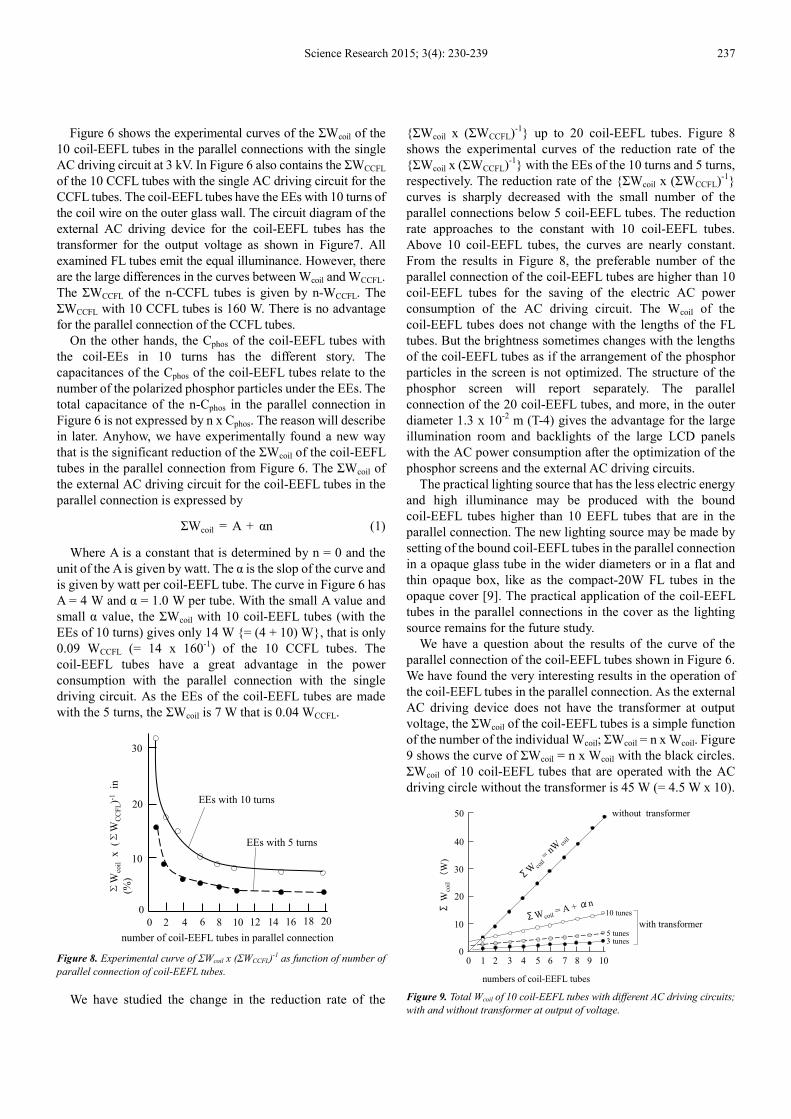
Figure 6 shows the experimental curves of the ΣWcoil of the
10 coil-EEFL tubes in the parallel connections with the single
AC driving circuit at 3 kV. In Figure 6 also contains the ΣWCCFL
of the 10 CCFL tubes with the single AC driving circuit for the
CCFL tubes. The coil-EEFL tubes have the EEs with 10 turns of
the coil wire on the outer glass wall. The circuit diagram of the
external AC driving device for the coil-EEFL tubes has the
transformer for the output voltage as shown in Figure7. All
examined FL tubes emit the equal illuminance. However, there
are the large differences in the curves between Wcoil and WCCFL.
The ΣWCCFL of the n-CCFL tubes is given by n-WCCFL. The
ΣWCCFL with 10 CCFL tubes is 160 W. There is no advantage
for the parallel connection of the CCFL tubes.
On the other hands, the Cphos of the coil-EEFL tubes with
the coil-EEs in 10 turns has the different story. The
capacitances of the Cphos of the coil-EEFL tubes relate to the
number of the polarized phosphor particles under the EEs. The
total capacitance of the n-Cphos in the parallel connection in
Figure 6 is not expressed by n x Cphos. The reason will describe
in later. Anyhow, we have experimentally found a new way
that is the significant reduction of the ΣWcoil of the coil-EEFL
tubes in the parallel connection from Figure 6. The ΣWcoil of
the external AC driving circuit for the coil-EEFL tubes in the
parallel connection is expressed by
ΣWcoil = A + αn (1)
Where A is a constant that is determined by n = 0 and the
unit of the A is given by watt. The α is the slop of the curve and
is given by watt per coil-EEFL tube. The curve in Figure 6 has
A = 4 W and α = 1.0 W per tube. With the small A value and
small α value, the ΣWcoil with 10 coil-EEFL tubes (with the
EEs of 10 turns) gives only 14 W {= (4 + 10) W}, that is only
0.09 WCCFL (= 14 x 160-1
) of the 10 CCFL tubes. The
coil-EEFL tubes have a great advantage in the power
consumption with the parallel connection with the single
driving circuit. As the EEs of the coil-EEFL tubes are made
with the 5 turns, the ΣWcoil is 7 W that is 0.04 WCCFL.
0
0
10
30
20
4 8 12 16 201814102 6
number of coil-EEFL tubes in parallel connection
EEs with 10 turns
ΣW
coil
x
(ΣW
CC
FL)-1
in
(%)
EEs with 5 turns
Figure 8. Experimental curve of ΣWcoil x (ΣWCCFL)-1 as function of number of
parallel connection of coil-EEFL tubes.
We have studied the change in the reduction rate of the
{ΣWcoil x (ΣWCCFL)-1
} up to 20 coil-EEFL tubes. Figure 8
shows the experimental curves of the reduction rate of the
{ΣWcoil x (ΣWCCFL)-1
} with the EEs of the 10 turns and 5 turns,
respectively. The reduction rate of the {ΣWcoil x (ΣWCCFL)-1
}
curves is sharply decreased with the small number of the
parallel connections below 5 coil-EEFL tubes. The reduction
rate approaches to the constant with 10 coil-EEFL tubes.
Above 10 coil-EEFL tubes, the curves are nearly constant.
From the results in Figure 8, the preferable number of the
parallel connection of the coil-EEFL tubes are higher than 10
coil-EEFL tubes for the saving of the electric AC power
consumption of the AC driving circuit. The Wcoil of the
coil-EEFL tubes does not change with the lengths of the FL
tubes. But the brightness sometimes changes with the lengths
of the coil-EEFL tubes as if the arrangement of the phosphor
particles in the screen is not optimized. The structure of the
phosphor screen will report separately. The parallel
connection of the 20 coil-EEFL tubes, and more, in the outer
diameter 1.3 x 10⁻²
m (T-4) gives the advantage for the large
illumination room and backlights of the large LCD panels
with the AC power consumption after the optimization of the
phosphor screens and the external AC driving circuits.
The practical lighting source that has the less electric energy
and high illuminance may be produced with the bound
coil-EEFL tubes higher than 10 EEFL tubes that are in the
parallel connection. The new lighting source may be made by
setting of the bound coil-EEFL tubes in the parallel connection
in a opaque glass tube in the wider diameters or in a flat and
thin opaque box, like as the compact-20W FL tubes in the
opaque cover [9]. The practical application of the coil-EEFL
tubes in the parallel connections in the cover as the lighting
source remains for the future study.
We have a question about the results of the curve of the
parallel connection of the coil-EEFL tubes shown in Figure 6.
We have found the very interesting results in the operation of
the coil-EEFL tubes in the parallel connection. As the external
AC driving device does not have the transformer at output
voltage, the ΣWcoil of the coil-EEFL tubes is a simple function
of the number of the individual Wcoil; ΣWcoil = n x Wcoil. Figure
9 shows the curve of ΣWcoil = n x Wcoil with the black circles.
ΣWcoil of 10 coil-EEFL tubes that are operated with the AC
driving circle without the transformer is 45 W (= 4.5 W x 10).
0 10
2 3 4 5 6 7 8 9 10
10
20
30
40
50
numbers of coil-EEFL tubes
ΣW
coil(
W)
without transformer
with transformer
ΣW co
il= n
Wco
il
ΣWcoil= A + αn
10 tunes
5 tunes3 tunes
Figure 9. Total Wcoil of 10 coil-EEFL tubes with different AC driving circuits;
with and without transformer at output of voltage.

238 Lyuji Ozawa: Coil-EEFL Tubes as Unrivaled Light Source with Small W
As the external AC driving circuit has the transformer
shown in Figure 7, the curve of the ΣWcoil drastically changes
from the n Wcoil. As the coil-EEFL tubes in the parallel
connection are operated with the AC driving circuit shown in
Figure 7, the ΣWcoil follows with Eq (1). Th
9 with the transformer shown in Figure 7 are
values of the Eq (1). The A-values of the Eq (1)
with the number of the turns of the lead wire on the outer
glass wall of the coil-EEFL tubes. Figure 9 shows
values with the 10 turns, 5 turns and 3 turns, respectively
with the transformer in Figure 7. The A value
changed with the number of the turns of the lead wire on the
outer glass wall of the EEFL tube. The slope of the three
curves have same α = 1.0.
Fortunately, we temporarily have the different AC driving
circuit that has the complicated transformer
the voltage of the AC driving circuit with 3 kV
The coil-EEFL tubes in the parallel connection
same A values but the different slope as α
1.0 in Eq. (1). The ΣWcoil of the 10 coil-EEFL tubes
EEs with the 5 turns is only 7 W (= 4 + 3 W) that is 0.04
WCCFL {= 7 W x (160 W)-1
}. The ΣWcoil with 20 coil
tubes is 10 W (= 4 + 6 W). The individual coil
have the same illuminance. Consequently, you may have the
20 times of the illuminance with 10 W of the AC power
consumption. The 20 coil-EEFL tubes in the parallel
connection can be operated with the combination of th
cell and battery. Unfortunately we do not have the circuit
designer around us. A very interesting subject that the
remarkable reduction of the ΣWcoil of the coil
the parallel connection remains for the future study by the
circuit designers.
Figure 10. Wcoil at n = 0 of coil-EEFL tubes in different outer diameters of
coil-EEFL tubes.
We have the preliminary studies on the A
different diameters of the coil-EEFL tubes with 5 turns
the future study. Figure 10 shows the experimental results.
The A-values have the linear function of the outer diameters
of the FL tubes. If the outer diameter of the coil
is 3.2 x 10⁻²
m (T-10), the ΣWcoil of the coil
given by ΣWcoil = 12 W + αn with the circuit in Figure 7.
ΣWcoil of the 10 coil-EEFL tubes is calculated with 22 W {=
12 + 10) W} that is 0.04 Wact of the 40W-
0 1.0 2.00
15
10
5
diameters of coil-EEFL tubes (x 10
12 W
6 W4 W
1.3 W
Wco
il(W
)
EEFL Tubes as Unrivaled Light Source with Small Wcoil Over Solid Light Sources
circuit has the transformer as
drastically changes
EEFL tubes in the parallel
connection are operated with the AC driving circuit shown in
follows with Eq (1). The curves in Figure
are the different A
Eq (1) are changed
with the number of the turns of the lead wire on the outer
Figure 9 shows the A
values with the 10 turns, 5 turns and 3 turns, respectively
A values are linearly
turns of the lead wire on the
The slope of the three
Fortunately, we temporarily have the different AC driving
transformer at the output of
with 3 kV and 50 kHz.
in the parallel connection have the
α = 0.3, instead of
EEFL tubes with the
7 W (= 4 + 3 W) that is 0.04
with 20 coil-EEFL
The individual coil-EEFL tubes
have the same illuminance. Consequently, you may have the
20 times of the illuminance with 10 W of the AC power
tubes in the parallel
can be operated with the combination of the solar
we do not have the circuit
designer around us. A very interesting subject that the
of the coil-EEFL tubes in
future study by the
EEFL tubes in different outer diameters of
We have the preliminary studies on the A-values of the
EEFL tubes with 5 turns for
shows the experimental results.
values have the linear function of the outer diameters
If the outer diameter of the coil-EEFL tubes
of the coil-EEFL tubes is
rcuit in Figure 7. The
EEFL tubes is calculated with 22 W {=
40W-HCFL tubes with
the inverter. Figure 11 shows the photopicture of the lighted
10 coil-EEFL tubes that have converted from the
40W-HCFL tubes that have selected from a store
illuminance of the individual
from the commercial 40W-HCFL tubes is about a half of the
40W-HCFL tubes. Total illuminance of the 10 coil
tubes is nearly 5 times of the original 40W
have 5 times of the illuminance with the one third of the AC
power consumption. The low illuminance of the coil
tubes is caused with (a) the low Ar gas pressure at 931 Pa (7
Torr) and (b) the deep depth (~ 1 x 10
screen and positive column of the lighted HCFL tubes.
Figure 11. Photograph of lighted 10 coil
10-2 m with 1.2 m long in parallel connection with single AC driving device
that supplies 4 kV with 50 kHz to the electrodes of EEs
The both Wcoil and the light intensity from the phosphor
screen of the coil-EEFL tubes d
between EEs on the FL glass tubes
evidently indicate no involvement of the C
coil-EEFL tubes. We have not optimized the performance of
the coil-EEFL tubes in this study. The remained subject of the
coil-EEFL tubes is the control of the change in the phosphor
screen. The optimization of the coil
the future study for some else
operated with the external DC electric circuit
zero [2]. The external DC electric circuits may
with the application of the piezoelectric transformer.
completion of the study on the
the lighting source will be made
future. The author wishes it.
4. Conclusion
The lighted FL tubes are operated with the disparate circuits
that are (a) the external AC driving circuit and
DC driving circuit, although the FL tubes are operated with the
single AC driving circuit. The lights of the FL tubes are
generated by the excitation of the Ar and Hg atoms with the
moving electrons in the internal DC driving circuit. The
external AC driving circuit is closed with the induced AC
current, not flowing electrons, from the capacitor C
role of the external AC circuit is the conjugation with the
internal DC electric circuit by the electric field from the
3.0
EEFL tubes (x 10-2 m)
12 W
Over Solid Light Sources
shows the photopicture of the lighted
that have converted from the commercial
that have selected from a store. The
individual coil-EEFL tubes converted
HCFL tubes is about a half of the
Total illuminance of the 10 coil-EEFL
f the original 40W-HCFL tube. We
have 5 times of the illuminance with the one third of the AC
The low illuminance of the coil-EEFL
tubes is caused with (a) the low Ar gas pressure at 931 Pa (7
Torr) and (b) the deep depth (~ 1 x 10⁻³
m) between phosphor
lumn of the lighted HCFL tubes.
Photograph of lighted 10 coil-EEFL tubes in outer diameter 3.2 x
m with 1.2 m long in parallel connection with single AC driving device
that supplies 4 kV with 50 kHz to the electrodes of EEs.
and the light intensity from the phosphor
FL tubes do not change with the distance
glass tubes. The experimental results
no involvement of the Ctube in the lighted
We have not optimized the performance of
EEFL tubes in this study. The remained subject of the
EEFL tubes is the control of the change in the phosphor
The optimization of the coil-EEFL tubes remains for
for some else. If the coil-EEFL tubes are
operated with the external DC electric circuit, the Wcoil will be
The external DC electric circuits may be produced
with the application of the piezoelectric transformer. The
the unrivaled coil-EEFL tubes as
will be made by someone else in the near
The lighted FL tubes are operated with the disparate circuits
the external AC driving circuit and (b) the internal
driving circuit, although the FL tubes are operated with the
The lights of the FL tubes are
generated by the excitation of the Ar and Hg atoms with the
moving electrons in the internal DC driving circuit. The
circuit is closed with the induced AC
current, not flowing electrons, from the capacitor Ctube. The
role of the external AC circuit is the conjugation with the
internal DC electric circuit by the electric field from the

Science Research 2015; 3(4): 230-239 239
electrodes of the lighted FL tubes. So far as the electrodes of
the external AC driving circuit vertically set at either outside
or inside of the ends of the FL tubes, the electrodes inevitably
pick up the large AC induced current from the capacitor Ctube.
The induced AC current at the electrodes determine the large
Wact of the external AC driving circuit. The large Wact does not
involve in the generation of the lights in the lighted FL tubes.
The reduction of the Wact of the external AC driving circuit is
the urgent subject for the energy saving of the lighted FL tubes.
This report has aimed the significant reduction of the Wact of
the external AC driving circuit by the application of the
coil-EEFL tubes.
It has found that coil-EEFL tubes significantly minimize the
Wcoil with no involvement in the Ctube in the operation. The
single coil-EEFL tube may reduce to 0.3 Wact. The further
reduction of the Wcoil is made with the parallel connection of
the coil-EEFL tubes with the single AC driving circuit with
the transformer at output. The ΣWcoil of 20 coil-EEFL tubes in
the parallel connection under the single AC driving circuit will
be down to 0.03 ΣWact of the commercial HCFL tubes. The
illuminance (lm m-2
) of the coil-EEFL tubes is determined by
the operation conditions of the internal DC electric power
generator that forms in the Ar gas space. The results suggest us
that the coil-EEFL tubes, that have the astronomical quantum
efficiency, are the unrivaled light source with the very small
Wcoil over the solid lighting sources, such as the LED lamps.
The study on the optimizations of the coil-EEFL tubes remains
for a future study by someone else.
Acknowledgement
The author wishes to express his great appreciation to Dr.
Takao Toryu for his deliberate instruction of this project.
References
[1] L. Ozawa and Y. Tian, “Coexistence of disparities of external AC driving circuit and internal DC electron circuit in operation of fluorescence tube”, J. China Ill. Engs. Soc., 6, 19-30, 2011
[2] L. Ozawa, “Development of prototype of coil-EEFL tubes”, Science Research, 3(4), pp 220-229, 2015
[3] F. M. Penning, “ Electrical discharges in gases, The Macmillan Company, New York, 1957
[4] J. F. Waymouth, “Electric Discharge Lamp”, MIT Press, 1971
[5] Handbook of “Electric Discharge lamps”, Japanese Institute of Electric Engineers, 1973
[6] American Vacuum society Classics, (1) The fundamental data on electrical discharge gases, (2) Field emission and field ionization, (3) Vacuum technology and space simulation, (4) The physical basics of ultrahigh vacuum, (5) Handbook of electron tube and vacuum techniques, (6) Vacuum sealing techniques, and (7) Ionized gases, American Institute of Physics, 1993
[7] L. Ozawa and Y. Tian, “A new 4G electron source for Fluorescent tubes, J. China Illu. Eng. Soc., 7, pp 58-65, 2012
[8] L. Ozawa and Y. Tian, “calculation of quantum efficiency of phosphor screens in CRTs and FL tubes, Korean J. Information display, 11, pp 128-133, 2010
[9] L. Ozawa, “Illuminance (lm m2) of compact 20W-HCFL tube”, Science Research, 3(4), pp 170-179, 2015.
[10] L. Ozawa, “illuminance of FL tubes controlled by depth of gap between positive column and phosphor screen”, Science Research, 3(2), pp 93-104, 2015
[11] L. Ozawa and T. Yakui, [Restriction of solid lighting sources in practical use], J. China Illu. Eng. Soc., 6, pp57-64, 2011
[12] L. Ozawa, “Figure 3-2 and Table 3-1 in Cathodoluminescence and Photoluminescence, theory and practical application”, CRC Press, Taylor & Francis, Group, Boca Raton, 2007
[13] L. Ozawa, “Cathodoluminescence”, Kodansha, Tokyo, Japan, 1990
[14] L. Ozawa and K. Oki, “307,200 pixels cm-2 resolution phosphor screen in monochrome CRT”, Materials chemistry and Physics, 60, 274-281, 1999
[15] L. Ozawa and M. Kato, “Coil-EEFL tube”, China Pat. 102,067,276, May 18, 2011; and Japan Pat. 4,923,110, Feb. 10, 2012
[16] L. Ozawa and Y. Tian, “Remarkable enhancement of luminance of coil-EEFL tubes setting in vacuum-sealed sheath tube”, J. China Ill. Engs. Soc., 8, 105-113, 2013.