COHFN WOLF - Connecticut
32
COHFN WOLF ~PC.~ ATTORNEYS AT LAW April 1, 2015 Attorney Melanie Bachman Acting Executive Director Connecticut Siting Council Ten Franklin Square New Britain, CT 06051 Re: Notice of Exempt Modification Danbury Hospital/T-Mobile equipment upgrade Site ID CT11108A 24 Hospital Avenue, Danbury Dear Attorney Bachman: JULIE D. KOHLER PLEASE REPLY TO: BrICJgep01~ WRITER'S DIRECT DIAL: ~ZO3~ 33~I-4~ r J7 E -Mail Address: [email protected] This office represents T -Mobile Northeast LLC ("T -Mobile") and has been retained to file exempt modification filings with the Connecticut Siting Council on its behalf. In this case, Danbury Hospital owns the existing building that hosts several wireless telecommunications facilities at 24 Hospital Avenue, Road, Danbury Connecticut (latitude 41.40506/ longitude -73.44555). The Council assumed jurisdiction of a facility at this site in Docket 79 in 1987 and has acknowledged multiple exempt modifications since that time. This facility is therefore within the Council's jurisdiction. T -Mobile intends to replace two (2) two antennas and add one (1) antenna and related equipment at this existing rooftop telecommunications facility in Danbury ("Danbury Facility"). Please accept this letter as notification, pursuant to R.C.S.A. § 16-50j-73, of construction which constitutes an exempt modification pursuant to R.C.S.A. § 16 -50j -72(b)(2). In accordance with R.C.S.A. § 16-50j-73, a copy of this letter is being sent to the Mayor, Mark D. Boughton and the property owner, Danbury Hospital. The existing Danbury Facility consists of a 134' 7" building on which T -Mobile currently has 3 rooftop mounted arrays and associated equipment. T -Mobile plans to replace two (2) antennas on each of two sectors (beta and gamma) and add an antenna to the alpha sector. The antennas in the alpha and beta sectors are at a centerline of 154 feet, and antennas are at a centerline of 127 feet in the gamma sector. T -Mobile will add RRUs (remote radio units) behind each ac~tenna. T -Mobile will also use spare fiber for the proposed antennas. (See the plans revised to March 10, 2105 attached hereto as Exhibit A). The existing Facility is Docket No. 79 contains no limitations or restrictions relevant to T-Mobile's proposed modifications. 1115 BROAD STREET 1SH DEER HILL AVENUE 3ZO POST ROAD WEST 6S~ ORANGE C~.NTER ROAD P.O. BOX 1H21 DANBURY, CT O6H1O WESTPORT, CT OSHHO ORANGE, CT 06477 BRIDGEPORT, CT OG6OI-IHZI Ts~: (203) 7922771 Tel: (203) 222-1034 'ILL: (203) 298-4066 'ILL: (203) 368-0211 Fax: (203) 791-8149 Fnx: (203) 227-1373 Fwac: (203) 298 068 Fnx: (203) 3949901
Transcript of COHFN WOLF - Connecticut

COHFNWOLF~PC.~ATTORNEYS AT LAW
April 1, 2015
Attorney Melanie BachmanActing Executive DirectorConnecticut Siting CouncilTen Franklin SquareNew Britain, CT 06051
Re: Notice of Exempt ModificationDanbury Hospital/T-Mobile equipment upgradeSite ID CT11108A24 Hospital Avenue, Danbury
Dear Attorney Bachman:
JULIE D. KOHLER
PLEASE REPLY TO: BrICJgep01~
WRITER'S DIRECT DIAL: ~ZO3~ 33~I-4~ rJ7
E-Mail Address: [email protected]
This office represents T-Mobile Northeast LLC ("T-Mobile") and has been retained tofile exempt modification filings with the Connecticut Siting Council on its behalf.
In this case, Danbury Hospital owns the existing building that hosts several wirelesstelecommunications facilities at 24 Hospital Avenue, Road, Danbury Connecticut (latitude41.40506/ longitude -73.44555). The Council assumed jurisdiction of a facility at this site inDocket 79 in 1987 and has acknowledged multiple exempt modifications since that time. Thisfacility is therefore within the Council's jurisdiction.
T-Mobile intends to replace two (2) two antennas and add one (1) antenna and relatedequipment at this existing rooftop telecommunications facility in Danbury ("Danbury Facility").Please accept this letter as notification, pursuant to R.C.S.A. § 16-50j-73, of constructionwhich constitutes an exempt modification pursuant to R.C.S.A. § 16-50j-72(b)(2). Inaccordance with R.C.S.A. § 16-50j-73, a copy of this letter is being sent to the Mayor, Mark D.Boughton and the property owner, Danbury Hospital.
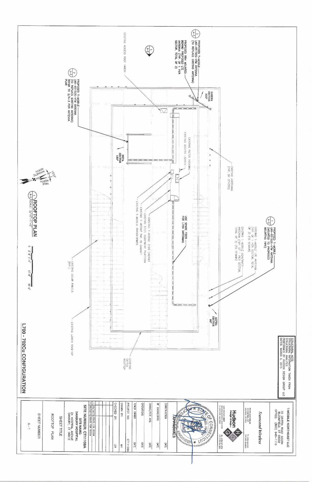
The existing Danbury Facility consists of a 134' 7" building on which T-Mobile currentlyhas 3 rooftop mounted arrays and associated equipment. T-Mobile plans to replace two (2)antennas on each of two sectors (beta and gamma) and add an antenna to the alpha sector.The antennas in the alpha and beta sectors are at a centerline of 154 feet, and antennas areat a centerline of 127 feet in the gamma sector. T-Mobile will add RRUs (remote radio units)behind each ac~tenna. T-Mobile will also use spare fiber for the proposed antennas. (See theplans revised to March 10, 2105 attached hereto as Exhibit A). The existing Facility is
Docket No. 79 contains no limitations or restrictions relevant to T-Mobile's proposed modifications.
1115 BROAD STREET 1SH DEER HILL AVENUE 3ZO POST ROAD WEST 6S~ ORANGE C~.NTER ROAD
P.O. BOX 1H21 DANBURY, CT O6H1O WESTPORT, CT OSHHO ORANGE, CT 06477BRIDGEPORT, CT OG6OI-IHZI Ts~: (203) 7922771 Tel: (203) 222-1034 'ILL: (203) 298-4066'ILL: (203) 368-0211 Fax: (203) 791-8149 Fnx: (203) 227-1373 Fwac: (203) 298 068Fnx: (203) 3949901

COHFNWOLF~EG~
April 1, 2015Site ID CT11108APage 2
structurally capable of supporting T-Mobile's proposed modifications, as indicated in thestructural assessment dated March 6, 2015 and attached hereto as Exhibit B.
The planned modifications to the Danbury Facility fall squarely within those activitiesexplicitly provided for in R.C.S.A. § 16-50j-72(b)(2).
1 . The proposed modification will not increase the height of the rooftop facility orthe antennas. T-Mobile's equipment is simply a replacement of existing equipment at thesame centerlines. The enclosed plans confirm that the proposed modification will not increasethe height of the Facility.
2 . T-Mobile's proposed equipment will be located entirely within the existingequipment area. No expansion of site boundaries is necessary,
3 . The proposed modification to the Facility will not increase the noise levels at theexisting facility by six decibels or more.
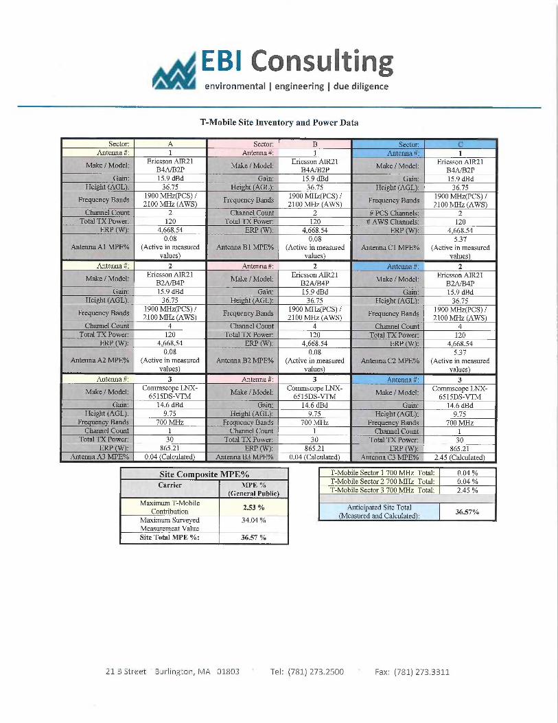
4 . The operation of the replacement and additional antennas will not increase thetotal radio frequency (RF) power density, measured at the nearest point of exposure (therooftop), to a level at or above the applicable standard. According to a Radio FrequencyEmissions Analysis Report prepared by EBI dated March 30, 2015, T-Mobile's operationswould add 2.53% of the FCC Standard. Therefore, the calculated "worst case" power densityfor the planned combined operation at the site including all of the proposed antennas would be36.57% of the FCC Standard as calculated for a mixed frequency site as evidenced by theengineering exhibit attached hereto as Exhibit C.
For the foregoing reasons, T-Mobile respectfully submits that the proposed replacementand additional antennas and equipment at the Danbury Facility constitutes an exemptmodification under R.C.S.A. § 16-50j-72(b)(2). Upon acknowledgement by the Council of thisproposed exempt modification, T-Mobile shall commence construction approximately sixtydays from the date of the Council's notice of acknowledgement.
Sincerely,
u ie D. Kohler, Esq.
cc: City of Danbury, Mayor Mark D. BoughtonDanbury HospitalElizabeth Jamieson, Transcend Wireless


SITE NAME: DAN BU RY HOSPITAL
24 HOSPITAL AVENUE
DAN B U RY, CT 06810
FAIRFIELD COUNTY
SITE NUMBER: CT11108A
L700 - 7
02Cu CONFIGURATION
GENERAL NOTES
1. THIS DOCUMENT IS T
HE CREATION, DESIGN, P
ROPERLY AND COPYRIGHTED WORK OF
T-MOBILE. ANY DUPLICATION
OR USE WITHOUT EXPRESS WRITTEN
CONSENT IS
STRICTLYPROHIBITED. DUPLICATION
AND USE BY GOVERNMENT AGENCIES FOR THE PURPOSES OF
CONDUCTING THEIR
LAWFULLY AUTHORIZED REGULATORY AND ADMINISTR4TIVE
FUNCTIONS IS
SPECIFICALLY ALLOWED.
2. THE FACILIT( IS
AN UNMANNED PRIVATE
AND SECURED EQUIPMENT INSTALLATION. IT
IS ONLY
ACCESSED BY TRAINED TECHNICIANS FOR PERIODIC
ROUTINE MAINTENANCE AND THEREFORE
DOES NOT REQUIRE ANY WATER OR SANITARY
SEWER SERVICE.
THE FACILITY
IS NOT
GOVERNED BY REGULATIONS REQUIRING PUBLIC ACCESS PER ADA RE4UIREMENTS.
3. CONTRACTOR SHALL VERIFY
ALL PLANS AND EXISTING
DIMENSIONS AND CONDITIONS ON THE
JOB SITE
AND SHALL IMMEDIATELY
NOTIF`( THE T-MOBILE NORTHEAST, LLC REPRESENTATIVE
IN WRITING
OF DISCREPANCIES BEFORE PROCEEDING WITH
THE WORK OR BE RESPONSI9LE
FOR SAME.
SPECIAL STRUCTURAL NOTES
t. STRUCTURAL DESIGNS AND DETAILS
FOR ANTENNA MOUNTS COMPLETED BY HUDSON DESIGN
ON BEHALF OF T-
MOBILE ARE INCLUSIVE
OF THE ENURE ANTENNA SUPPORT STRUCTURE
(GLOBAL STRUCTURAL
STABILITY ANALYSIS
BY
OTHERS),
EXISTING TOWER
PLATFORM,
D(ISTING ANTENNA MOUNTS AND ALL OTHER ASPECTS OF THE STRUCTURE THAT WILL
SUPPORT THE T-~AOBILE
MODERNIZATION EQUIPMENT DEPLOYMENT AS DEPICTED HEREIN.
2. HUDSON DESIGN ASSUMES THAT THE TOWER IS
PROPERLY CONSTRUCTED ANA MAINTAINED.
ALL STRUCTURAL MEMBERS AND THEIR
CONNECTION ARE ASSUMED TO BE
IN GOOD
CONDfTION AND ARE FREE FROM DEFECTS WITH
NO DETERIORATION
TO RS MEMBER
CAPACffIES
(APPROVALS
'PROJECT MANAGER
DATE
CONSTRUCTION
DATE
RF ENGINEERING
DATE
ZONING /SITE ACQ_
DATE
OPERATIONS
DATE
TOWER OWNER
DATE
,gyp .:,
Hfi ~
4 ,
~ i,~ ,
.. ~ ~n.~~~ s,~r~~„~~~5omrb+ry ~ospi~d
A
;,.w~,s~~P,F~~~~P~,,,~ PROJECT
~~~~,.s ,,,~r~_
.,.SITEKwrrr_mt~
~r~ ".y ~.on.-,
. 4=
V too'
_ c .
.zf,
CALL
BEFORE YOU DIG
CALL TOLL FREE 8~0-922-4455
OR CALL B
UNDERGROUND SERVICE ALERT
T-MOBILE TECHNICIAN S1TE SAFETY NOTES
LOCATION
SPECIAL RESTRICTIONS
SECTOR A:
ACCESS NOT PERMITTED
SECTOR B:
ACCESS NOT PERMITTED
SECTOR C:
ACCESS NOT PERMITTED
GPS/LMU:
UNRESTRICTED
RADIO CABINETS:
UNRESTRICTED
PPC DISCONNECT:
UNRESTRICTED
MAIN CIRCUIT D
/C:
UNRESTRICTED
NIU~T DEMARC:
UNRESTRICTED
OTHER/SPECIAL:
NONE
PROJECT INFORMATION
SCOPE OF WORK:
UNMANNED TELECOMMUNICATIONS FACILITY T-
MOBILE
EQUIPMENT MODERNIZATION
ZONING JURISDICTION:
BASED ON INFORMATION
PROVIDED BY T-
MOBILE, THIS
TELECOMMUNICATIONS EQUIPMENT DEPLOYMENT IS
AN
ELIGIBLE FACILITY
UNDER THE TAX RELIEF A
CT OF 2012,
47 USC 1455(A), A
ND IS
SUBJECT TO AN EXPEQITED
ELJGIBLE FACILITIES
REQUEST/REVIEW AND ZONING
PRE-EMPTION FOR LOCAL DISCREf10NARY PERMITS
(VARIANCE, SPECIAL PERMIT, SITE
PLAN REVIEW).
SITE ADDRESS:
24 HOSPITAL AVENUE
DANBURY, CT 06810
LATITUDE: 41' OB' 26.95" N
LONGITUDE:
73' 16~
10.42" W
JURISDICTION: NATIONAL, S
TATE &LOCAL CODES OR ORDINANCES
CURRENT USE:
TELECOMMUNICATIONS FACILITY
PROPOSED USE:
TELECOMMUNICATIONS FACILITY
DRAWING INDEX
REV
T-1 TITLE SHEET
0
GN-1 GENERAL NOTES
0
A-1 ROOFTOP PLAN
0
A-2 ELEVATION
0
A-3 ANTENNA PLAN &MOUNTING DETAIL
0
G-1 GROUNDING DETAILS
0
T-MOBILE NORTHEAST LLC
35 GRIFFIN
ROAD SOUTH
BLOOMFIELD, CT 06002
OFFICE: (B60) 648-1116
Transcend Wire%ss
TRANSCEND WIRELESS
101NDUSIRI~L AVE
del-j3ni}604LA55MAHWAH, NJ 07430
~-Ak:~;019 6B4D066
Hudson~~
Deign Graapuc
1600 0SGOOD STREET
9UIlDING 20 NORiH. Sl1RE 3090
TEI: 1978 557-5553N.AN~OVER, MA OIB45
FA%'R97B]33~SSB6
d~t1tlN~ rinhgi,
~~~~~.~~``q~ C~NN~.c~~~..~,f.
.0 '\
~
~ ~ A
C
~
~- -
~~rri~ C~1Etl- ~`~` ~~~`~~~
A
Y~ ALS
CONSTRUCTION DATE
RF ENGINEERING DATE
ZONING/SITE ACQ. DATE
OPERATIONS GATE
TOWER OWNER
DAB
PROJECT Nd:
CT111Q8A
DRAWN BY:
MH
CHECKED BY:
DR
1 D3/1Of15 ISSUED FOR REVIEW
0 82/23/15 ISSUED FOR REVIEW
SITE NUMBER: CT11108A
SITE NAME;
DANBURY HOSPITAL
24 HOSPITAL AVENUE
DANBURY, CT 06810
SHEET TITLE
TITLE SHEET
SHEET NUMBER
T-1

GROUNDING NOTES
THE SUBCOMRACTOR SHALL REVIEW
AND INSPECT T
HE
IXISi1NG FACILITY G
ROUNDING SYSTEM
AND LIGHTNING
PROTECTION SYSTEM (
AS QESIGNED A
ND INSTALLED) F
OR
STRICT COMPLIANCE WITH THE NEC (AS ADOPTED
Blf THE
AHJ), THE SITE-SPECiFlC (UL, LPI, O
R NF~A) LIGHTING
PROTECTION CODE, A
ND GENER4L COMPLJANCE WITH
TELCORDIA AND TIA G
ROUNDING STANDARDS. T
HE
SUBCONTRACTOR SHALL REPORT ANY VIOLAT10N5 O
RADVERSE FlN~INGS T
O THE CONTRACTOR FOR RESOLUTION.
2. ALL GROUND ELECTRODE SYSTEMS (INCLUDING
TELECOMMUNICATION, R4DI0, LIGHTNING PROTECTION, A
ND
AC POWER GES'S) S
HALL BE BONDED TOGETHER, AT O
RBELOW GRADE,. 6
Y lW0 OR MORE COPPER BONDING
CONDUCTORS IN
ACCORDANCE WITH T
HE NEC.
3. THE SUBCONTRACTOR SHALL P
ERFORM IEEE
FALL-OF-POTENTIAL RESISTANCE T
O EARTH TESTING (
PER IEEE
110D AND 81) FQR
NEW GROUND ELECTRODE SYSTEMS. T
HE
SUBCONTRACTOR SHALL FURNISH
AND INSTALL
SUPPLEMENTAL GROUND ELECTRODES A
S NEEDED T
OACHIEVE A TEST RESULT O
F 5 OHMS OR LESS.
4. METAL RACEWAY SHALL N
OT BE USED AS THE NEC
REQUIRED EQUIPMENT G
ROUND CONDUCTOR. STR4NDED
COPPER CONDUCTORS WITH
GREEN INSULATION, SIZED IN
ACCORDANCE WITH T
HE NEC, S
HALL BE FURNISHED A
ND
INSTALLED WITH T
HE POWER CIRCUITS T
Q BTS EQUIPMENT.
5. EACH BTS CABINET F
RAME SHALL B
E DIRECTLY
CONNECTED TO THE MASTER
GROUND BAR WITH
GREEN
INSULATED SUPPLEMENTAL EQUIPMENT G
RQUND WIRES, 6
AWG STRANDED COPPER OR IARGER
FOR INDOOR
BTS 2 AWG
STRANDED COPPER FOR OUTDOOR BTS.
6. IXOTHERMIC WELDS SHALL B
E USED FOR ALL G
ROUNDING
CONNECTIONS BELOW GRADE.
7. APPROVED AN110XIDANT COATINGS (I.E., C
ONDUCTNE GEL
OR PASTE) SHALL B
E USED
ON ALL C
OMPRESSION AND
BOLTED GROUND CONNECTIONS.
8. ICE BRIDGE BONDING CONDUCTORS SHALL BE
EXOTHERMICALLY BONDED OR BOLTED T
O THE BRIDGE A
ND
THE TOWER GROUND BAR.
9. ALUMINUM CONDUCTOR OR COPPER CLAD STEEL
CONDUCTOR SHALL N
OT BE USED FOR GRQUNDING
CONNECTIONS.
10. MISCELLANEOUS ELECTRICAL A
ND NON-ELECTRICAL
METAL BOXES, FRAMES AND SUPPORTS SHALL BE BONDED
TO THE GROUND RING, IN
ACCORDANCE WI1H T
HE NEC.
11. METAL CON~Uff SHALL BE MADE ELECTRICALLY
CONTINUOUS WITH LISTED
BONDING FlTTINGS O
R BY
BONDING ACROSS 11iE DISCONTINUITY WITH 6
AWS COPPER
WIRE UL APPROVED GROUNDING TYPE CONDUIT CLOMPS.
12. ALL NEW STRUCTURES WITH
A FOUNDATION AND/OR FOOTING
HAVING 20 Ff_
OR MORE OF 1/2 IN. O
R GREATER
ELECTRICALLY CONDUCTIVE REINFORCING STEEL MUST HAVE IT
BONDED TO THE GROUND RING
USING AN EXOTHERMIC WELD
CONNECTION USING #2 AWG SOLID
BARE TINNED COPPER
GROUND WIRE, P
ER NEC 250.50
GENERAL NOTES
1. FOR THE PURPOSE OF CONSTRUCTION DRAWING, THE FOLLOWING
DEFlNffIONS SHALL APPLY:
CONTRACTOR -TRANSCEND WIRELESS
SUBCONTRACTOR -GENERAL CONTRACTOR (CONSTRUCTION)
OWNER - T -
MOBILE
2. PRIOR TO THE SUBMISSION OF BIDS, T
HE BIDDING
SUBCONTRACTOR SHALL
VI51T THE CELL SITE T
O FAMILIARIZE
WITH THE IXISTING
CONDITIONS AND TO
CONFIRM THAT THE WORK GAN BE ACCOMPLISHED AS SHOWN ON THE
CONSTRUCTION DRAWINGS. ANY DISCREPANCY FOUND SHALL BE BROUGHT TO
THE ATTENTION
OF CONTRACTOR.
3. ALL MATERIALS
FURNISHED AND INSTALLED
SHALL BE IN
STRICTACCORDANCE WITH
ALL APPLICABLE CODES, REGULATIONS, AND ORDINANCES.
SUBCONTRACTOR SHALL ISSUE ALL APPROPRIATE NOTICES AND COMPLY WITH
ALL LAWS, ORDINANCES, RULES, REGULATIONS, AND LAWFUL ORDERS OF ANY
PUBLIC AUTHORITY REGARDING THE PERFORMANCE OF THE WORK. ALL WQRK
CARRIED OUT SHALL COMPLY WITH
ALL APPLICABLE MUNICIPAL A
ND UTILfTY
COMPANY SPECIFICATIONS A
ND LOCAL JURISDICTIONAL C
ODES, ORDINANCES AND
APPLICABLE REGULATIONS.
4. DRAWINGS PROVIDED HERE ARE NQT TO BE SCALED AND ARE INTENDED
TO SHOW OUTLINE ONLY.
5. UNLESS NOTED OTHERWISE, THE WORK SHALL INCLUDE FURNISHING
MATERIALS, EQUIPMENT, APPURTENANCES, AND LABOR NECESSARY TO COMPLETE
ALL INSTALLATIONS A
S INDICATED
ON THE DRAWINGS.
6.
"KITTING LIST" S
UPPLIED WITH
THE BID
PACI(AGE IDENTIFIES ITEMS T
HAT
WILL BE SUPPLIED BY CONTRACTOR. ITEMS
NOT INCLUDED IN
THE BILL O
FMATERIALS
AND KITTING
L15T SHALL BE SUPPLIED BY THE SUBCONTRACTOR.
7. THE SUBCONTR,4CTOR SHALL INSTALL A
LL EQUIPMENT AND MATERIALS
INACCORDANCE WITH
MANUFACTURER'S RECOMMENDATIONS UNLESS SPECIFICALLY
STATED OTHERWISE.
S.
IF THE SPECIFlED
EQUIPMENT CANNOT BE INSTALLED
AS SHOWN ON THESE
DRAWINGS, THE SUBCONTRACTOR SHALL PROPOSE AN ALTERNATIVE INSTALLATION
SPACE FOR APPROVAL BY THE CONTRACTOR.
9. SUBCONTRACTOR SHALL DETERMWE ACTUAL ROUTWG OF CONDUIT, POWER
AND T1
CABLES, GROUNDING CABLES AS SHOWN 4N THE POWER, GROUNDING
AND TELCO PLAN DRAWING. SUBCONTRACTOR SHALL UTILIZE
EXISTING TRAYS
AND/OR SHALL ADD NEW TRAYS AS NECESSARY. SUBCONTRACTOR SHALL
CONFIRM THE ACTUAL ROUTING WITH
THE CONTRACTOR.
10. THE SUBCONTRACTOR SHALL PROTECT EXISTING
IMPROVEMENTS,
PAVEMENTS, CURBS, LANDSCAPING AND STRUCTURES. ANY DAMAGED PART
SHALL BE REPAIRED AT SUBCONTRACTOR'S IXPENSE TO THE SATISFACTION
QF
OWNER.
11. SUBCONTR4CTOR SHALL LEGALLY
AND PROPERLY DISPOSE OF ALL SCRAP
MATERIALS SUCH AS COAXIAL C
ABLES AND OTHER ITEMS
REMOVED FROM THE
EXISTING FACILITY.
ANTENNAS REMOVED SHALL BE RETURNED TO THE OWNER'S
DESIGNATED LOCATION.
12. SUBCONTRACTOR SHALL LEAVE PREMISES IN
CLEAN CONDITION.
13. ALL CONCRETE REPAIR
WORK SHALL BE DONE IN
ACCORDANCE WITH
AMERICAN CONCRETE INSTITUTE (ACT) 3
01.
14. ANY NEW CONCRETE NEEDED FOR THE CONSTRUCTION SHALL BE
AIR-ENTRAINED AND SHALL HAVE 4000 PSi S
TRENGTH. AT 28 DAYS. ALL
CONCRETE WORK SHALL BE DONE IN
ACCORDANCE WITH
ACI 318 CODE
REQUIREMENTS.
15. ALL STRUCTURAL STEEL WORK SHALL BE DETAILED, F
ABRICATED AND ERECTED
IN ACCORDANCE WITN
NSC SPECIFICATIONS. A
LL STRUCTUR,4L STEEL SHALL BE
ASTM A36 (Fy = 36 ksi)
UNLESS OTHERWISE NOTED.
PIPES SHALL BE ASTM A53
T(PE E (Fy = 36 ksi).
ALL STEEL EXPOSED TO WEATHER SHALL BE HOT DIPPED
GALVANIZED. TOUCHUP ALL SCR,4TCHES A
ND OTHER MARKS IN
THE FIELD
AFTERSTEEL IS
ERECTED USING A COMPATIBLE ZINC RICH
PAINT.
16. CONSTRUCTION SHALL COMPLY WITH
UMTS SPECIFICATIONS
AND "GENERAL
CONSTRUCTION SERVICES FOR CONSTRUCTION OF T-
MOBILE SITES."
17. SUBCONTRACTOR SHALL VERIFY
ALL EXISTING
DIMENSIONS AND CQNDITIONS
PRIOR TO COMMENCWG ANY WORK. ALL DIMENSIONS OF EXISTING
CONSTRUCTION
SHOWN ON THE DRAWINGS MUST BE VERIFIED.
SUBCONTRACTOR SHALL NOTIFY
THE CONTRACTOR OF ANY DISCREPANCIES PRIOR TO ORDERING MkTERIAL
OR
PROCEEDWG WITH
CONSTRUCTION.
18. THE EXISTING
CELL SITE
IS IN
FULL COMMERCIAL OPERATION. ANY
CONSTRUCTION WDRK BY SUBCONTRACTOR SHALL NOT DISRUPT THE EXISTING
NORMAL OPERATION. ANY WORK ON EXISTING
EQUIPMENT MUST BE COORDINATED
WITH CONTRACTOR. ALSO, WORK SHOULD BE SCHEDULED FOR AN APPROPRIATE
MAINTENANCE WINDOW USUALLY IN
LOW TRAFFIC
PERIODS AFTER MIDNIGHT.
19. SINCE THE CELL SITE
IS ACTIVE, A
LL SAFETY PRECAUTIONS MUST BE TAKEN
WHEN WORKING AROUND HIGH
LEVELS OF ELECTROMAGNETIC RADIATION.
EQUIPMENT SHOULD BE SHUTDOWN PRIOR
TO PERFORMING ANY WORK THAT
COULD EXPOSE THE WORKERS TO DANGER. PERSONAL RF IXPOSURE MONITORS
ARE ADVISED
TO BE WORN TO ALERT OF ANY DANGEROUS EXPOSURE LEVELS.
20. APPLICABLE BUILDING
CODES:
SUBCONTRACTOR'S WQRK SHALL COMPLY WRH ALL APPLICABLE NATIONAL, STATE,
AND LOCAL CODES AS ADOPTED BY THE LOCAL AUTHORITY HAVING
JURISDICTION(AHJ) FOR THE LOCATION.
THE EDITION
OF THE AHJ ADOPTED CODES AND
STANDARDS IN
EFFECT ON THE DATE OF CONTR4CT AWARD SHALL GOVERN THE
DESIGN.BUILDING
CODE: IBC 2
003 Wf 2D05 CT SUPPLEMENT + 2009 AMENDMENT
ELECTRICAL CODE: REFER TO ELECTRICAL
DRAWINGS
LIGHTENING CODE: REFER TO ELECTRICAL
DRAWINGS
SUBCONTRACTOR'S WORK SHALL COMPLY WffH
THE LATEST EDITION
OF THE
FOLLOWING STANDARDS:
AMERICAN CONCRETE INSTITUTE (ACT} 3
i8; BUILDING
CODE
REQUIREMENTS FOR STRUCTURAL CONCRETE;
AMERICAN INSTITUTE
OF STEEL CONSTRUCTION {AISC)
MANUAL OF STEEL CONSTRUCTION, ASD, NINTH
EDITION;
TELECOMMUNICATIONS INDUSTRY ASSOCIATION (TIA) 2
22-F,
STRUCTURAL STANDARDS FOR STEEL
ANTENNA TOWER AND ANTENNA SUPPORTING STRUCTURES; REFER
TO ELECTRICAL DRAWINGS FOR SPECIFIC
ELECTRICAL STANDARDS.
FOR ANY CONFLICTS BETWEEN SECTIONS OF LISTED
CODES AND STANQARDS
REGARDING MATERIAL,
METHODS OF CONSTRUCTION, OR OTHER REQUIREMENTS,
THE MOST RESTRICTIVE R
EgUIREMENT SHALL GOVERN. WHERE THERE IS
CONFLICT
BETWEEN A GENERAL REQUIREMENT AND A SPECIFIC
REQUIREMENT, THE SPECIFlC
REQUIREMENT SHALL GOVERN.
ABBREVIATIONS
AGL
ABOVE GRADE LEVEL
G.C. GENERAL CONTRACTOR
RF
RADIO FREQUENCY
AWG
AMERICAN WIRE
GAUGE
MGB
MASTER GROUND BUS
BCW
BARE COPPER WIRE
MIN MINIMUM
TBD
TO BE DETERMINED
BTS
BASE TRANSCEIVER STATION PROPOSED
NEW
THR
TO BE REMOVED
EXISTING EXISI7NG N.T.S.
NOT TO SCALE
TBRR
TO BE REMOVED
EG
EQUIPMENT GROUND
REF
REFERENCE
AND REPLACE➢
EGR
EQUIPMENT GROUND RING
REq
REQUIRED
NP
TYPICAL
T-MOBILE NORTHEAST LLC
35 GRIFFIN
ROAD SOUTH
BLOOMFIELD, CT 06002
OFFICE: (860) 648-1116
Transcend Wrrefess
7ftANSCET~D WI6aFS5t01NDUSiRIALAVE
1F1: ~2D1~68d-0055MAHWAH N1 W
4~0
CA[~1~684-0066
Hudson~~
~~~
I6000SGOOD STREET
6111L~ING 20NORIH SIIliE 309D
TEL•~978)557-3553N.ANDOVER, M
A010/5
FAX; ~97B~3365586
t ~„1pµ111 I I I! I u t t~~i~rr
,q ,.,.~pZ .,~
?~•. C~`G~
'~
~ fi~
~ -
5z
A ~+Iq~'1~ S
CONSTRUCTION DATE
RF ENGINEERING DATE
ZONING/STYE ACQ. DATE
DPERNTIONS DATE
TQWER OWNER
DATE
PROJECT N0:
CT11108A
DRAWN BY:
MH
CHECKED BY:
DR
1 U3/i0/75 ISSUED FOR REVIEW
4 02/3/15 ISSUED FOR F2EVIEW
SITE NUMBER: CT11108A
SITE NAME:
DANBURY HOSPITAL
24 HOSPITAL AVENUE
DANBURY, CT 06810
SHEET TITLE
GENERAL NOTES
SHEET NUMBER
GN-1


STAINLESS
STEEL
HARDWARE
GROUNDING
TWO HOLE COPPER
COMPRESSION TERMINAL
ANTENNA
-ANTENNA SUPPORT
(NP. OF 1 PER
PIPE (NP )
SECTOR, TOTAL OF3)
RRU (NP. OF 3)
C
~~ ~~ - EGB
:f
POWER PANEL
TOWER
~~I TELCO CABINET
-UTILITY
CONDUITS
CABLE TRAYS
~, S
EXISTING ~ ',}~
Li ~--~~
EXISTING 3106
~
CABI ET
CABINET ~j
i~ G
G
Gl
a: —.~~11 .7~ ~- EGB
_ . .-
EQUIPMENT PAD
fi -~ ---
G
G
MGB
TO EXIST. G
ROUND
CONNECTION
2 GROUNDING RISER DIAGRAM
G-1 N.T.S.
FROM AIVTENNA-
T-MOBILE NORTHEAST LLC
35 GRIFFlN
ROAD SOUTH
BLOOMFIELD, CT 06002
OFFICE: (86~) 648-1116
Tf8/75C8R[~ W1f~~E.'S5
TRANSCEND WIRELESS101NDU5iRIAl A
VE
TEL: ~201~6849055MAHWAH. NJ 07030
FAX:IZ01)6840066
Hudson~~
Des}grt Gra~pac
1600 0.5GOOD STREET
BUILDING YO NORTH, SURE 3090 iEl: ~97BJ 557-5553
N. AN~OVFR, MA01845
FAX: ~97B~336.5586
\````«~~a atluniunt~rpr ~` 'i\,,,~
o f c
o~v~F`~~~,,,,-,3~' --a
~ ~
~
i ̀
~~`~
,`
AP
l"J'V~` S
CONSTRUCTION DAlE
RF ENGINEERING DAIS
ZONING/SITE ACQ. DATE
OPERATIONS DATE
TOWER OWNER
QATE
PROJECT N0:
CT11108A
DR,4WN BY:
MH
CHECKED BY:
DR
1 OS/ID/IS ISSUED FOR REVIEW
0 02/23/15 ISSUED FOR REVIEW
SITE NUMBER: CT11108A
SITE NAME:
DANBUHY HOSPITAL
24 HOSPITAL AVENUE
DANBURY, CT 06810
SHEET TITLE
GROUNDING DETAILS
SHEET NUMBER
G-1
GROUND BAR
LOCK WASHER,
FLAT WASHER, NP.
SNP"~
3/8"x1-1/4" HEX
NUT, NP.
BOLT
GROUND BAR
GROUNDING
EXPOSED BARE COPPER TO BE
CABLE
KEPT TO ABSOLUTE MINIMUM, N
OINSULATION
ALLOWED WITHIN
THE
SECTION "A-
A"
COMPRESSION TERMINAL (TYPICAL)
NOTE:
1. DOUBLING UP" OR "STACKING
OF CONNECTION IS
NOT PERMITTED.
2. OXIDE INHlBIT1NG
COMPOUND TO BE USED AT ALL LOCATIONS.
3. CADWELD DOWNLEADS FROM UPPER EGB, LOWER EGB, AND MGB.
TYPICAL GROUND BAR
CONNECTION DETAIL
G-1 N.T.S.
JUMPER REQUIRED ONL'
WHEN T-1/4"~ AND
L4RGER (NP.)
CONNECTOR
WEATHERPROOFING
KR ~P•~
FROM ANTENNA
FRAME SUPPORT
WEATHERPROOFlNG
KIT (NP.)
STANDARD
GROUND KIT (
NP.)
T~T6TS A~TMP~ E
COAX GROUND KIT
COMMSCOPE KIT
N0. GB-0414-IT
OR EQUAL
#2 AWG BCW
A~2 AWE BCW. BONDED
r0 GROUND WIRE ALONG
CA9LE L4DOER TO CIGBE/MIGB
NOTE:
1. D0 NOT INSTALL C
ABLE GROUND KIT
AT A BEND AND ALWAYS
DIRECT GROUND WIRE DOWN TO CIGBE.
GROUND WIRE TO GROUND
~ BAR CONNECTION DETAIL
~-~ N.T.S.
TO ANTENNA
GROUND LUG ~~
- T'~~ I I
ANTENNA GROUND ~ ~fJ
~~ -STANDARD
BAR (CIGBE) (TOP)
b
L ./
GROUNDING KIT
SEE NOTE 1.
/~~
(NP.)
~'—
~fi AWG (PROVIDED
#2 AWG BCW LUG
~ ~'~'~T~'~
GRQUNDINC
(TMP.) r~ KIT
NP)
~`
I ~ HYBRID/COAX
CABLES
—
(NP. FOR ALL)
ANTENNA GROUND
STANDARD GROUND
BAR (CIGBE)
KIT (NP.)
(BOTTOM) SEE
NOTE 1.
__~ i'
#6 AWG LOG
(2) #2 AWG BCW
1
~ TO BTS VIA
TRAY OR ICEBRIDGE
~~~- -i
GRADE
#2 AWG BCW
-" - ,
RING GROUND
NOTE:
1. NUMBER QF GROUND BARS MAY VARY DEPENDING ON THE TYPE OF
TOWER. ANTENNA LOCATION AND CONNECTION ANTENNA LOCATION
AND CONNECTION ORIENTATION. PROVIDE AS REQUIRED.
2. A SEPARATE GROUND BAR TO BE USED FOR GPS ANTENNA IF
REQUIRED.
~ ANTENNA CABLE GROUNDING
~-~ N.T.S.


HudsonDesign Group~tc
March 6, 201 S
Transcend WireEess
Transcend Wireless10 Industrial AvenueMahwah, NJ 07430
RE; T-Mobile Site Number:Site Name:Site Address:
To Whom It May Concern:
d
CT11108ADanbury Hospital24 Hospital AvenueDanbury, CT 06810
Hudson Design Group LLC (HDG) has been authorized by Transcend Wireless to perform a structural assessment onthe above mention site to determine its capability of supporting the proposed antennas:
• (3) Commscope LNX-6515DS-VTM antennas (1 per sector) mounted on proposed/existing steel pipes.
• (3) RRUS-1 1 RRH's (1 per sector) mounted behind the antennas.
Based on our evaluation, we have determined that the existing structure IS CAPABLE of supporting the proposedantenna installation. HDG reviewed the existing and proposed antenna loading along with field photographs todetermine this assessment. Reference the latest HDG construction drawings for the proposed antenna locations andattachment details.
This assessment was conducted in accordance with EIA/TIA-222-F, Structural Standards for Steel Antenna Towers andAntenna Supporting Structures, the International Building Code 2003 with 2005 Connecticut Supplement with 2009Amendments, and the ASCE 7-05 Minimum Design Loads for Buildings and Other Structures.
Reference Documents:
• Construction Drawings prepared by Atlantis Group dated September 18, 2013.
• Structural Evaluation Letter prepared by Atlantis Group dated September 19, 2013.
This determination was based on the following limitations and assumptions:
1. HDG is not responsible for any modifications completed prior to and hereafter which HDG was not directlyinvolved.
2. All structural members and their connections are assumed to be in good condition and are free from defectswith no deterioration to its member capacities. Contractor is to perform apre-inspection to confirm.
3. All antennas, coax cables and waveguide cables are assumed to be properly installed and supported asper the manufacturer's requirements.
4. All the components supporting the T-Mobile antennas mounts are assumed to be designed to all applicablecodes and designed for identical to or larger than the currently proposed loads.
5. The new and existing mounts have been adequately secured to the building structure.
Please feel free to contact our office should you have any questions. \\~~~~~~~"'~~F CONS;"',,,,,,~~~
Respectfully Submitted, ~~?.•'p~ ~2 ̀ iceHudson Design Group LLC _ ̀'~ ~ ~ ~:G~
- s24 ~~~<l/
/I , ~ ~' rvs~o ~'~ ~.
~ C ~ / ~ /` ~~ ~`~'~+NA~ntisu„a~ua~̀~̀
Michael Cabral Daniel P. Hamm, PEStructural Dept. Head Principal
p: 978.557.5553 f: 978.336.5586 a: 1600 Osgood Street, Building 20 North, Suife 3090, N. Andover, MA 01845p: 413.588.8139 f: 413.517.0590 a: 116 Pleasant Street, Ste 302, Easthampton, MA 01027


EBI Consulting~, environmental ~ engineering ~ due diligence
RADIO FREQUENCY EMISSIONS ANALYSIS REPORTEVALUATION OF HUMAN EXPOSURE POTENTIAL
TO NON-IONIZING EMISSIONS
ON SITE MEASUREMENTS PERFORMED: MARCH 24, 2015
T-Mobile Existing Facility
Site I D: CT11108A
Danbury Hospital24 Hospital AvenueDanbury, CT 06810
March 30, 2015
EBI Project Number: 6215001609
Site Compliance Summary
Compliance Status: COMPLIANT
Site total MPE% ofFCC general public 36.57allowable limit:
21 B Street Burlington, MA 01803 Tel: (781) 273.2500 Fax: (781) 273.3311

E61 Consultingenvironmental ~ engineering ~ due diligence
March 30, 2015
T-Mobile USAAttu: Jason Overbey, RF Manager35 Griffin Road SouthBloomfield, CT 06002
Emissions Analysis for Site: CT11108A —Danbury Hospital
EBI Consulting was directed to analyze the proposed T-Mobile facility located at 24 Hospital Avenue,
Danbury, CT, for the purpose of determining whether the emissions from the Proposed T-Mobile
.Antenna Installation located on this property are within specified federal limits. For this analysis, power
density measurements were taken on site by EBI Consulting's field technicians on March 24, 2015 to
determine the e~sting radio frequency (RF) emissions values present on and surrounding the rooftop
walking surface of the hospital. Theoretical calculations were then performed to determine the additional
contribution to this composite value from the proposed T-Mobile upgrades to the existing facility
All information used in this report was analyzed as a percentage of current Maximum Permissible
Exposure (% MPE) as listed in the FCC OET Bulletin 65 Edition 97-Oland ANSI/IEEE Std C95.1. The
FCC regulates Maximum Permissible Exposure in units of microwatts per square centimeter (µW/cm2).
The number of µW/cmZ calculated at each sample point is called the power density. The exposure limit
for power density varies depending upon the frequencies being utilized. Wireless Carriers and Paging
Services use different frequency bands each with different exposure limits, therefore it is necessary to
report results and limits in terms of percent MI'E rather than power density.
All results were compaxed to the FCC (Federal Communications Commission) radio frequency exposure
rules, 47 CFR 1.1307(b)(1) — (b)(3), to determine compliance with the Maximum Permissible Exposure
(MPE) limits for General Population/iJncontrolled environments as defined below.
General po~ulation/uncontrolled exposure limits apply to situations in which the general public may be
exposed or in which persons who are exposed as a consequence of their employment may not be made
fully aware of the potential for exposure or cannot exercise control over their exposure. Therefore,
members of the general public would always be considered under this category when exposure is not
employment related, for example, in the case of a telecommunications tower that exposes persons in a
nearby residential area.
2Z B Street Burlington, MA 01803 Tel: (7II1) 273.2500 Fax: (781) 273.3311

E61 Consultingenvironmental ~ engineering ~ due diligence
Public exposure to radio frequencies is regulated and enforced in units ofmicrowatts per square
centimeter (µW/cm2). The general population exposure limit for the 700 MHz Band is 467 µW/cm2, and
the general population exposure limit for the PCS and AWS bands is 1000 µW/cm2. Because each carrier
will be using different frequency bands, and each frequency band has different exposure limits, it is
necessary to report percent of MPE rather than power density.
OccupationaUcontrolled exposure limits apply to situations in which persons are exposed as a
consequence of their employment and in which those persons who are exposed have been made fully
aware of the potential for exposure and can exercise control over their exposure. OccupationaUcontrolled
exposure limits also apply where exposure is of a transient nature as a result of incidental passage through
a location where exposure levels maybe above general population/uncontrolled limits (see below), as
long as the exposed person has been made fully aware of the potential for exposure and can exercise
control over his or her exposure by leaving the area or by some other appropriate means.
Additional details can be found in FCC OET 65.
MEASUREMENT METHODOLOGY
Frequencies from 300 KHz to 50 GHz were measured using the Narda EA5091 probe in conjunction with
the NBM 550 survey meter. The EA5091 probe is "shaped" such that in a mimed signal environment (i.e.:
more than one frequency band is used in a particular location) it accurately measures the percent of MI'E.
FCG OET Bulletin No. 65 -Edition 97-01 states "A useful characteristic of broadband probes used in
multiple-frequency RF environments is afrequency-dependent response that corresponds to the variation
in MPE limits with frequency. Broadband probes having such a "shaped" response permit direct
assessment of compliance at sites where RF fields result from antennas transmitting over a wide range of
frequencies. Such probes can express the composite RF field as a percentage of the applicable MPEs".
Probe Description — As suggested in FCC OET Bulletin No. 65 -Edition 97-01, the response of the
measurement instrument should be essentially isotropic, (i.e., independent of orientation or rotation angle
of the probe). For this reason, the Narda EA5091 Isotropic probe was used for these measurements.
Sampling Method: At each measurement location, a spatially averaged measurement is collected over the
height of an average human body. The NBM 550 survey meter performs a time average measurement
while the user slowly moves the probe over a distance range of 0 cm to 200 cm (about 6 feet) above
ground level. The results recorded at each measurement location include both average and peak values
over the spatial distance.
21 B Street Burlington, MA 01803 Tel: (781) 273.2500 Fax: (781) 273.3311

'~EBI Consulting,,~ environmental ~ engineering ~ due diligence
A summary of equipment specifications for the probe and meter are listed in Table 1 below.
Manufacturer: NARDA Microwave
Probe Model: NARDA EA5091
Probe Calibration date: September 17, 2014
Survey Meter Model: NARDA NBM 550
Survey Meter calibration Date: September 8, 2014
Calibration Interval: 24 Months
Probe Specifics
Frequency Range: 300 KHz to 50 GHz
Fields) Measured: E Field
Measurement Range (% of ControlledEnvironment standard): 0.3 to 600%
Specification Standards: FCC 1997
Table 1: Measurement Equipment Information
Instrument Measurement Uncertainty: The total measurement uncertainty of the NARDA measurementprobe and meter is no greater than ±3 d8. The factors which contribute to this include the probe'sfrequency response deviation, calibration uncertainty, ellipse ratio, and isotropic response. Every effort istaken to reduce the overall uncertainty during measurement collection including rotating the probe aboutthe axis of the handle and pointing the probe directly at the likely highest source of emissions.
A summary of all sample points taken on site are displayed in Appendix A
21 B Street Burlington, MA 01803 Tel: (781) 273.2500 Fax: (781) 273.3311

EB1 Consulting~, environmental ~ engineering ~ due diligence
CALCULATIONS
Calculations were done for the proposed T-Mobile Wireless antenna facility located at 24 Hospital
Avenue, Danbury, CT, using the equipment information listed below. All calculations were performed
per the specifications under FCC OET 65. Since T-Mobile is proposing highly focused directional panel
antennas, which project most of the emitted energy out toward the horizon, all calculations were
performed utilizing the actual antenna gains in the direction of the rooftop were used per the
manufacturers' specifications. These values are approximately 33 dB lower than the maximum gain of the
antennas.
For all calculations, all equipment was calculated using the following assumptions:
1) Existing 2 GSM channels (PCS Band - 1900 MHz) were considered for each sector of theproposed installation. These Channels have a transmit power of 30 Watts per Channel.(Captured in Measured Values)
2) E~sting 2 UMTS channels (AWS Band — 2100 MHz) were considered for each sector of theproposed installation. These Channels have a transmit power of 30 Watts per Channel.(Captured in Measured Values)
3) E~sting 2 LTE channels (AWS Band — 2100 MHz) were considered for each sector of theproposed installation. These Channels have a transmit power of 60 Watts per Channel.(Captured in Measured Values)
4) Proposed 1 LTE channel (700 MHz Band) was considered for each sector of the proposedinstallation. This channel has a transmit power of 30 Watts.(Calculated and Added to Measured Values)
5) All radios at the proposed installation were considered to be running at full power and wereuncombined in their RF transmissions paths per carrier prescribed configuration. Per FCCOET Bulletin No. 65 -Edition 97-01 recommendations to achieve the maximum anticipatedvalue at each sample point, all power levels emitting from the proposed antenna installationare increased by a factor of 2.56 to account for possible in-phase reflections from thesurrounding environment. This is rarely the case, and if so, is never continuous.
6) For the following calculations the sample point was the top of a six foot person standing atthe base of the tower. For all rooftop calculations the actual antenna gains in the direction ofthe rooftop were used per the manufacturers' specifications. These values are approximately33 dB lower than the maximum gain of the antennas. The sample point for all calculationswas the top of a 6 foot person on the rooftop walking surface.
21 B Street Burlington, MA 01803 Tel: (781) 273.2500 Fax: (781) 273.3311

E61 Consultingenvironmental ~ engineering ~ due diligence
7) The antennas used in this modeling are the Ericsson AIR21 B4A/B2P& B4A/S2P) for 1900
MHz (PCS) and 2100 MHz (AWS) channels and the Commscope LNX-6515DS-VTM for
700 MHz channels. This is based on feedback from the carrier with regards to anticipated
antenna selection. The Ericsson AIR21 B4A/B2P& B4A/B2P) have a ma~mum gain of
15.9 dBd at their main lobe. The Commscope LNX-6515DS-VTM has a maximum gain of
14.6 dBd at its main lobe. For these rooftop calculations the actual antenna gains in the
direction of the rooftop were used per the manufacturers' specifications. These values are
approxirriately 33 dB lower than the maximum gain of the antennas.
8) The antenna mounting. height centerline of the proposed antennas is 36.75 feet above ground
level (AGL).
9) Composite emissions value measurements were taken on site to determine existing RF
emissions levels. The largest calculated theoretical emissions value for the T-Mobile
proposed facility upgrades (700 MHz antennas) was then added to the largest power density
value measured on site to determine the anticipated largest onsite composite value with the
contribution of the proposed T-Mobile facility upgrade. The e~sting T-Mobile equipment
operating in the 1900 MHz and 2100 MHz bands was measured during the survey and was
not calculated as part of this study to prevent duplicate contributions.
All calculations were done with respect to uncontrolled /general public threshold limits.
21 B Street Burlington, MR 01803 Tel: (781) 273.2500 Fax: (781) 273.3311
E61 Consultinenvironmental ~ engineering I due diligence
T-Mobile Site Inventory and Power Data
Sector: A Sector: $ Sector: ~'Antenna #: 1 Antenna #: 1 Antenna #: 1
Ericsson AIR21 Ericsson f1IIZ21 Ericsson AII221Make /Model: B4A/B2P
Make !Mode]: B4~2P Make /Model: B4A/B2P
Gain: 15.9 dBd Crain_ 15.9 dBd Gain: 15.9 dBdHei ht (AGL : 36.75 Hei t (AGL : 36.75 He" ht (AGL): 36.75
Frequency Bands 1900 MHz(PCS) /
Frequency Bands 1900 MIIz(PCS) /
Frequency Bauds 1900 MHz(PCS) /
21Q0 MHz (AWS) 2100 NIIIz (AWS) 2100 MHz (AWS)Channel Count 2 Channel Count 2 # PCS ChanueLs: 2
Total TX Power: 12a Total TX Power. 120 # AVJS Channels: 120ERP (4~: 4,668.54 ERP (4~: 4,668.54 ERP 4,668.54
0.08 0.08 537Antenna Al MPE% (Active in measured tlntenna Bl MPE% (Active in measured Antenna Cl MPE% (Active in measured
values values values
Antenna #: 2 Antenna #: 2 Anteima #: 2Ericsson AIlZ21 Ericsson ATR21 Ericsson AIR21Make /Model:
BZA/B4P Make /Model:
B2A/B4P Make /Model_
B2A/B4PGain. 15.9 dBd Gain_ 15.9 dBd Gain: 15.9 dBd
Hei t AGL : 36.75 Hei ht (AGL : 36.75 Hei ht AGL : 36.75
Frequency Bands 1900 MHz(PCS) /
Frequency Bands 1900 MHz(PCS) /
Frequency Bands 1900 MHz(PCS) /
2100 MHz AWS) 2100 MI3z (AWS) 2100 MHz (AWS)Channel Count 4 Channel Count 4 Chazmel Count 4
Total TX Power: 120 Total TX Power: 120 Total TX Power: 120ERP (V~: 4,668.54 ERP 4;668.54 ERP 4,668.54
0.08 0.08 537Antenna A2 MPE°Jo (Active in measured Antenna B2 MPE% (Active in measured Antenna C2 MPE°/a (Active m measured
values values values)
Antenna #: 3 Antenna #: 3 Antenna #: 3Commscope LNX- Commscope LNX- Commscope LNX-Make /Model: 6515DS-VTM
Make /Model: 6515DS-VTM
Make / ModeL- SS 15DS-VTM
Gain: 14.6 dBd Gain: 14.6 dBd Gain: 14.6 dBdHei t (AGL : 9.75 Hei t (AGL : 9.75 Hei ht (AGL : 9.75
Fre enc Bands 700 MHz Fre enc Bands 700 MFIz Fre uenc Bands 700 MHzChannel Count 1 Channel Count 1 Channel Count 1
Total TX Power: 30 Total TX Power: 30 Total TX Power: 30ERP (V~: 86521 ERP 865.21 ERP 86521
Antenna A3 MPE% 0.04 (Calculated) Antenna B3 MPE% 0.04 (Calculated) Antenna C3 MPE% 2.45 (calculated)
Site Com osite MPE%Carrier MPE
General PublicMaz~imum T-Mobile
2,53Contribution
Maximum Surveyed 34.04 °/aMeasurement ValueSite Total MPE %: 36.57
T-Mobile Sector 1 700 MHz Total: 0.04T-Mobile Sector 2 700 MHz Total: 0.04T-Mobile Sector 3 700 MHz Total: 2.45
Anticipated Site Total 36.57%
(Measured and Calculated):
21 B Street Burli~~gton, MA 01803 Tel: (781) 273..2500 Fax: (781) 273.3311

EBI ~onsultingenvironmental ~ engineering ~ due diligence
Summary
All calculations performed and measurements taken on site for this analysis yielded results that werewithin the allowable limits for general public exposure to RF Emissions.
The anticipated maximum composite contributions from the T-Mobile facility as well as the sitecomposite emissions value with regards to compliance with FCC's allowable limits for general publicexposure to RF Emissions are shown here:
T-Mobile Sector Power Density Value (%)Sector l: 0.04Sector 2: 0.04 %Sector 3 : 2.45
T-Mobile Total: 2.53%
Site Total: 36.57%
Site Com lance Status: COMPLIANT
The largest value observed while conducting the on-site measurements was 34.04% of the allowablelimits for general public exposure to RF Emissions.
The anticipated composite MPE value for this site assuming all carriers present is 36.57% of theallowable FCC established general public limit sampled on the rooftop level. All ground levels will be farbelow values measured and calculated for the rooftop walking area.
FCC guidelines state that if a site is found to be out of compliance (over allowable thresholds), thatcarriers over a 5%contribution to the composite value will require measures to bring the site intocompliance. For this facility, the composite values calculated were well within the allowable 100%threshold standard per the federal government.
----Scott Heffernan
RF Engineering Director
EBI Consulting
21 B Street
Burlington, MA 01803
2Z B Street Burlington, MA 01803 Tel: (781) 273.2500 Fax: (781) 273.3311

EBI Consulting,~ environmental ~ engineering ~ due diligence
On Site Measurements
Z1 B Street Burlington, MA 01803 Tel: (781) 273.2500 ~ Fax: (781) 273.3311

EBI Consultingenvironmental ~ engineering ~ due diligence
Accessible Areas on RooftopFCC MPE
Spatial Averages
Location Reference %Occupational MPE %General
Population MPE
1' in front of T-Mobile Sector A 0.2697 1.34853' in front of T-Mobile Sector A 0.2273 1.13656' in front of T-Mobile Sector A Inaccessible Inaccessible
Behind T-Mobile Sector A 0.2156 1.07801' in front of T-Mobile Sector B 0.4097 2.04853' in front of T-Mobile Sector B 0.4569 2.28456' in front of T-Mobile Sector B 0.4475 2.2375
Behind T-Mobile Sector B Inaccessible Inaccessible1' in front of T-Mobile Sector C Inaccessible Inaccessible3' in front of T-Mobile Sector C Inaccessible Inaccessible6' in front of T-Mobile Sector C Inaccessible Inaccessible
Behind T-Mobile Sector C Inaccessible InaccessibleATT Sector B 0.2203 1.1015ATT Sector B 0.2465 1.2325ATT Sector B 1.98 9.9000
behind VZW B 1.055 5.2750E roof door 0.759 3.7950VZW Sector A 0.3652 1.8260SPT Sector A 0.1281 0.6405ATT Sector A 0.2992 1.4960
Upper roof 0.1879 0.9395Upper roof 0.2521 1.2605Upper roof 0.444 2.2200TMO equip 0.715 3.5750TMO equip 1.096 5.4800Upper roof 2.556 12.7800W roof hatch 2.859 14.2950E roof hatch 6.807 (Maximum) 34.0350 (Maximum)
N roof 0.1198 0.5990VZW Sector C 1.547 7.7350VZW Sector C 2.365 11.8250VZW Sector C 2.071 10.3550VZW Sector C 2.443 12.2150ATT Sector C 2.492 12.4600
21 B Street Burlington, MA 01803 Tel: (781) 273.2500 Fax: (781) 273.3311

EB1 Consulting~r~; environmental ~ engineering ~ due diligence
Accessible Areas at Ground LevelFCC MPE
Spatial Averages
Location Reference %Occupational MPE %General
Population MPE
Ground 1 0.123 0.6150Ground 2 0.1184 0.5920Ground 3 0.0897 0.4485
21 B Street Burlington, MA 01803 Tel: (781) 273.2500 Fax: (781) 273.3311

E61 Consulting~ environmental ~ engineering ~ due diligence
APPENDIX B
Site Photos
21 B Street Burlington, MA 01803 Tel: (781) 273.2500 Fax: (781) 273.3311

~,,
;f
Verizon Sector B antennas
~~
~•~ ~►~-7~' K Ik 1 a !i
NOT ANE~(IF
wax -
~' ' I=_--
2. Signage on east roof access door
G~ N~TIC~~
A~~uTiaN
r_.,..~,.. _..~ ~~._
- ..~..~~.~~,F,,,~«.
T • -5k}bur~
3. Signage beside east roof access door
E81 Consulting

EBI Consulting

__ iti
~~~~~-}
3. T-Mobile Sector C signage
-.. _~
:_
:~ —r - -r
14. T-Mobile Sector C broadcast direction
;t,,.
15. Sprint Sector C antennas
EBI Consulting

Yr
~y t~
I~~
't ,,~ ~
~1~; ~ ~~~,.
~~~
- -
~ ~ I,~ ,.~.F~
~; -
' ~f ~~y.
~W~:
~9a.~D
p ~- -....
• •
~~p~~
4{ih7L{7
1
INF(NjMAi IG4
• • 1 1 •
EBI Consulting

~i
,'i
,f~
Verizon Sector B antennas
e
J
1 ~.~..
M lr f
N~QT AN ~EXIT
•~' ~,+ ~
~~ - _=— ,
2. Signage on east roof access door
~NC~TICE~~ w5hw4F
~uar~ ~il~c~
~~AUTIQN
L~~i~~~ L~:'~
::~
-_—__ ~.c ~~i7lilH~di~ _
F ~ ~Mubik~-
3. Signage beside east roof access door
r .~
_~.,
t~.~ '~ ~, ~ rt e.~.E
4. Signage on east upper roof access hatch
r
— _
5. AT&T Sector B antennas
:~
J
6. Verizon Sector A antennas above and T-Mobile Sector B antennas below
EBI Consulting

EBI Consulting

r .,
6. Verizon Sector B antennas, I of 2
17. Verizon Sector B antennas, 2 of 2
,:~~;.
8. Sprint (left) and unknown (right) Sector C
EBI Consulting
1'
`.
J~ ~)
f ~ ~ t.¢ ~
I ~~~ ~ - ~ ~t ~~►Q0 ~ ~■A -
`~/
~~ r
/ ~ I\~
•
~,
~. T -~, ~,~.
~.
L 4/~.~s
.~. -~a~-
~ ,~ 9
~ - ••
~~
i
14F hR.NAI l~h
• • 1 1 •
EBI Consulting

.~ ~
~.~~-
j y r _ .~_u
~~
`~1.r.~y
w.~
~~
25. Signage on west roof access hatch
-~^
,~ ~•-;.
„K
~
---~.r ~'
..
Y ~ r~̀
r ~ ,
26. Verizon Sector A antennas
P
~ k
27. Sprint (left) and T-Mobile (right) Sector Bantennas
~~iL
- fi
4.~, .``r ~~— - r=~~..
~ -~
r _... ' e. ~.. _
1 a~ •.a~~-;~i_
~~c
~ ~
4- _e -4
'~~ P~ ,~ a1~1
.._ .. ..
r 1~~
+z ~~r-- + ~
y'~~ . ~ _.:__
-~LL ~ w - -
.. -.
`y;.
'~' - ~
y YP,~ Nl~~~i~_ ,-~/1~.d
' .:f~ -, '!
i~ ,~F ~ ~ ~aw~ ~t
l -~__ _ - -
~ - - -.
EBI Consulting