
Coherent and Non-coherent Techniques for Cooperative...
190
Coherent and Non-coherent Techniques for Cooperative Communications Ph.D Kai Zhu University of York Electronics May 2014
Transcript of Coherent and Non-coherent Techniques for Cooperative...

Coherent and Non-coherent Techniquesfor Cooperative Communications
Ph.D
Kai ZhuUniversity of York
Electronics
May 2014

Abstract
Future wireless network may consist of a cluster of low-complexity battery-powerednodes or mobile stations (MS). Information is propagated from one location in the net-work to another by cooperation and relaying. Due to the channel fading or node fail-ure, one or more relaying links could become unreliable during multiple-hop relaying.Inspired by conventional multiple-input multiple-output (MIMO) techniques exploitingmultiple co-located transmit antennas to introduce temporal and spatial diversity, the errorperformance and robustness against channel fading of a multiple-hop cooperative networkcould be significantly improved by creating a virtual antenna array (VAA) with variousdistributed MIMO techniques. In this thesis, we concentrate on the low-complexity dis-tributed MIMO designed for both coherent and non-coherent diversity signal reception atthe destination node.
Further improvement on the network throughput as well as spectral efficiency could beachieved by extending the concept of unidirectional relaying to bidirectional cooperativecommunication. Physical-layer network coding (PLNC) assisted distributed space-timeblock coding (STBC) scheme as well as non-coherent PLNC aided distributed differ-ential STBC system are proposed. It is confirmed by the theoretical analysis that bothapproaches have the potential for offering full spatial diversity gain.
Furthermore, differential encoding and non-coherent detection techniques are generallyassociated with performance degradation due to the doubled noise variance. More im-portantly, conventional differential schemes suffer from the incapability of recovering thesource information in time-varying channels owing to the assumption of static channelmodel used in the derivation of non-coherent detection algorithm. Several low-complexitysolutions are proposed and studied in this thesis, which are able to compensate the per-formance loss caused by non-coherent detection and guarantee the reliable recovery ofinformation in applications with high mobility. A substantial amount of iteration gain isachieved by combining the differential encoding with error-correction code and sufficientinterleaving, which allows iterative possessing at the receiver.
K. Zhu, Ph.D. Thesis, Department of Electronics, University of York
ii2014

Contents
Abstract ii
List of Figures ix
List of Tables xvi
Acknowledgements xviii
Declaration xx
1 Introduction 1
1.1 Historical Perspective and State-of-the-Art . . . . . . . . . . . . . . . . . 1
1.2 MIMO and Diversity Techniques . . . . . . . . . . . . . . . . . . . . . . 3
1.3 Space-Time Coding . . . . . . . . . . . . . . . . . . . . . . . . . . . . . 4
1.4 Organization of Thesis . . . . . . . . . . . . . . . . . . . . . . . . . . . 6
1.5 Novel Contributions . . . . . . . . . . . . . . . . . . . . . . . . . . . . . 7
1.6 Notations . . . . . . . . . . . . . . . . . . . . . . . . . . . . . . . . . . 8
K. Zhu, Ph.D. Thesis, Department of Electronics, University of York
iii2014

CONTENTS iv
2 Theory of Space-Time Block Coding 9
2.1 Space-Time Block Codes . . . . . . . . . . . . . . . . . . . . . . . . . . 10
2.1.1 Evolution of Space-Time Coding . . . . . . . . . . . . . . . . . 11
2.1.1.1 STBC from Orthogonal Design . . . . . . . . . . . . . 11
2.1.1.2 Space-Time Code from Layered Design . . . . . . . . 12
2.1.1.3 Linear Dispersion Codes . . . . . . . . . . . . . . . . 13
2.1.2 Orthogonal Space-Time Block Codes . . . . . . . . . . . . . . . 15
2.1.2.1 Alamouti Space-Time Encoding . . . . . . . . . . . . 15
2.1.2.2 Alamouti Space-Time Decoding Using ML Algorithm . 16
2.1.2.3 Alamouti Scheme Decoding with Multiple ReceiveAntennas . . . . . . . . . . . . . . . . . . . . . . . . . 20
2.1.2.4 Performance Evaluation of Alamouti STBC Scheme . . 21
2.2 Differential Space-Time Block Codes (DSTBCs) . . . . . . . . . . . . . 24
2.2.1 Evolution of DSTCs . . . . . . . . . . . . . . . . . . . . . . . . 25
2.2.1.1 Differential Unitary Space-Time Modulation . . . . . . 26
2.2.1.2 Differential STBC from Orthogonal Design . . . . . . 26
2.2.2 Orthogonal Differential Space-Time Block Codes (O-DSTBC) . . 27
2.2.2.1 Differential Technique for Single-antenna Transmis-sion: DPSK . . . . . . . . . . . . . . . . . . . . . . . 27
2.2.2.2 Differential Technique for Multiple-antenna Transmis-sion: ODSTBC . . . . . . . . . . . . . . . . . . . . . 29
K. Zhu, Ph.D. Thesis, Department of Electronics, University of York 2014
CONTENTS v
2.2.2.3 Encoding of Differential Alamouti Code . . . . . . . . 30
2.2.2.4 Receiver and Non-coherent Decoding . . . . . . . . . . 34
2.2.2.5 Decoding with Multiple Receive Antennas . . . . . . . 36
2.2.2.6 Performance Evaluation of Differential STBC Scheme . 37
2.3 Conclusion . . . . . . . . . . . . . . . . . . . . . . . . . . . . . . . . . 46
3 Cooperative Space-Time Block Codes 47
3.1 Cooperative Communication and Relaying . . . . . . . . . . . . . . . . . 47
3.1.1 Distributed Space-Time Coding . . . . . . . . . . . . . . . . . . 49
3.1.2 Two-way Relay Channel and Existing Two-way Relaying Strategies 51
3.2 Cooperative Space-Time Block Codes for Bidirectional Relaying . . . . . 53
3.2.1 Physical-Layer Network Coding (PLNC) . . . . . . . . . . . . . 53
3.2.2 Design of Distributed STBC aided Two-way Relaying System . . 55
3.2.2.1 System Model . . . . . . . . . . . . . . . . . . . . . . 55
3.2.2.2 Principle of CRC-based Selective Relaying . . . . . . . 57
3.2.3 Performance Results, Comparison and Discussion . . . . . . . . 62
3.3 Numerical Analysis of Distributed STBC aided Two-way Relaying System 66
3.3.1 Mathematical Preliminaries . . . . . . . . . . . . . . . . . . . . 66
3.3.2 Upper and Lower Bound of Average End-to-End BEP for Pro-posed Distributed STBC System . . . . . . . . . . . . . . . . . . 68
3.3.3 Exact Average End-to-End BEP for Proposed Distributed STBCSystem . . . . . . . . . . . . . . . . . . . . . . . . . . . . . . . 71
K. Zhu, Ph.D. Thesis, Department of Electronics, University of York 2014

CONTENTS vi
3.4 Conclusion . . . . . . . . . . . . . . . . . . . . . . . . . . . . . . . . . 73
4 Cooperative Differential Space-Time Block Codes 75
4.1 Cooperative Differential Space-Time Block Codes for Unidirectional Re-laying . . . . . . . . . . . . . . . . . . . . . . . . . . . . . . . . . . . . 76
4.1.0.1 System Model . . . . . . . . . . . . . . . . . . . . . . 77
4.1.0.2 Proposed Two-hop Cooperative DSTBC Scheme withSelection Relaying . . . . . . . . . . . . . . . . . . . . 78
4.1.0.3 Design of Distributed DSTBC Encoding and Decoding 79
4.1.0.4 Performance Results and Discussion . . . . . . . . . . 81
4.1.0.5 Theoretical Performance Analysis . . . . . . . . . . . 84
4.1.0.6 Extension to Turbo-coded Distributed DSTBC Scheme 88
4.2 Cooperative Differential Space-Time Block Codes for Bidirectional Re-laying . . . . . . . . . . . . . . . . . . . . . . . . . . . . . . . . . . . . 91
4.2.1 System Model and Design . . . . . . . . . . . . . . . . . . . . . 92
4.2.1.1 Differential Physical-layer Network Coding for Two-way Fading Channel . . . . . . . . . . . . . . . . . . . 96
4.2.1.2 Performance Results and Discussion . . . . . . . . . . 101
4.3 Conclusion . . . . . . . . . . . . . . . . . . . . . . . . . . . . . . . . . 106
5 Iterative Detection of Channel-coded Differential Schemes in Fast FadingChannels 108
5.1 Principle of Iterative Decoding . . . . . . . . . . . . . . . . . . . . . . . 108
5.1.1 Log-Likelihood Ratio (LLR) . . . . . . . . . . . . . . . . . . . . 109
K. Zhu, Ph.D. Thesis, Department of Electronics, University of York 2014
CONTENTS vii
5.1.2 Maximum A-Posteriori (MAP) Algorithm . . . . . . . . . . . . . 110
5.1.2.1 Principle of MAP Algorithm . . . . . . . . . . . . . . 110
5.1.2.2 Logarithmic MAP Algorithm . . . . . . . . . . . . . . 112
5.1.3 SISO APP Decoder . . . . . . . . . . . . . . . . . . . . . . . . . 114
5.2 Low-complexity Iterative Non-coherent Detection of DifferentialSchemes in Fast Fading Channels . . . . . . . . . . . . . . . . . . . . . 115
5.2.1 Historical Review of Differential Schemes under Fast FadingChannels . . . . . . . . . . . . . . . . . . . . . . . . . . . . . . 115
5.2.2 Log-MAP Decoding of Uncoded DPSK Signal: A Near-CoherentPerformance Approach . . . . . . . . . . . . . . . . . . . . . . . 123
5.2.2.1 Trellis Representation of Differentially-encoded PSKSignal . . . . . . . . . . . . . . . . . . . . . . . . . . 123
5.2.2.2 APP DPSK Decoder . . . . . . . . . . . . . . . . . . . 125
5.2.2.3 Decision Feedback Differential Detection (DFDD)aided DPSK Decoder . . . . . . . . . . . . . . . . . . 126
5.2.2.4 Performance Results and Observations . . . . . . . . . 128
5.2.3 Turbo Principle aided Detection and Decoding of Channel-codedDifferential PSK . . . . . . . . . . . . . . . . . . . . . . . . . . 131
5.2.3.1 System Model . . . . . . . . . . . . . . . . . . . . . . 131
5.2.3.2 Non-coherent DPSK Demapper . . . . . . . . . . . . . 132
5.2.3.3 Semi Non-coherent Approaches Using EstimatedChannel . . . . . . . . . . . . . . . . . . . . . . . . . 133
5.2.3.4 Performance Results and Observations . . . . . . . . . 136
K. Zhu, Ph.D. Thesis, Department of Electronics, University of York 2014

CONTENTS viii
5.3 Conclusion . . . . . . . . . . . . . . . . . . . . . . . . . . . . . . . . . 149
6 Conclusions 150
6.1 Summary of Work . . . . . . . . . . . . . . . . . . . . . . . . . . . . . . 150
6.2 Future Work . . . . . . . . . . . . . . . . . . . . . . . . . . . . . . . . . 152
Appendices 153
A Derivation of Upper and Lower Bounds of the Average End-To-End BEP 154
Glossary 156
Bibliography 170
K. Zhu, Ph.D. Thesis, Department of Electronics, University of York 2014
List of Figures
2.1 Various factors that affect the design of space-time codes (STCs). . . . . . 9
2.2 The schematic of a two-branch Alamouti transmit diversity scheme encoder. 15
2.3 The schematic of a two-branch Alamouti transmit diversity scheme receiver. 18
2.4 Eb/N0 versus BER performance of Alamouti STBC invoking 2 transmitantennas and single receive antenna in quasi-static flat Rayleigh-fadingchannel. QPSK and 16PSK with Gray/SP mapping are investigated. . . . 22
2.5 Eb/N0 versus BER performance of Alamouti STBC invoking 2 trans-mit antennas and 2/4 receive antennas in quasi-static flat Rayleigh-fadingchannel. QPSK and 16PSK with Gray/SP mapping are investigated. . . . 23
2.6 The transmitter schematic of differentially-encoded PSK modulation. . . 28
2.7 The schematic of differential Alamouti STBC employing two transmitantennas. . . . . . . . . . . . . . . . . . . . . . . . . . . . . . . . . . . 30
2.8 The receiver schematic of differential Alamouti STBC employing one re-ceive antenna. . . . . . . . . . . . . . . . . . . . . . . . . . . . . . . . . 34
2.9 Error rate performance comparison between Alamouti STBC with coher-ent decoding and differential Alamouti STBC with non-coherent decod-ing. Nt = 2 transmit antennas and Nr = 1/2/4 receive antennas areemployed for transmission at 1 bit/sec/Hz over quasi-static flat Rayleigh-fading channel. . . . . . . . . . . . . . . . . . . . . . . . . . . . . . . . 39
K. Zhu, Ph.D. Thesis, Department of Electronics, University of York
ix2014

LIST OF FIGURES x
2.10 Error rate performance comparison between Alamouti STBC with coher-ent decoding and differential Alamouti STBC with non-coherent decod-ing. Nt = 2 transmit antennas and Nr = 1/2/4 receive antennas areemployed for transmission at 2 bit/sec/Hz with Gray mapping over quasi-static flat Rayleigh-fading channel. . . . . . . . . . . . . . . . . . . . . . 40
2.11 Error rate performance comparison between Alamouti STBC with coher-ent decoding and differential Alamouti STBC with non-coherent decod-ing. Nt = 2 transmit antennas and Nr = 1/2/4 receive antennas areemployed for transmission at 2 bit/sec/Hz with SP mapping over quasi-static flat Rayleigh-fading channel. . . . . . . . . . . . . . . . . . . . . . 41
2.12 Error rate performance comparison between Alamouti STBC with coher-ent decoding and differential Alamouti STBC with non-coherent decod-ing. Nt = 2 transmit antennas and Nr = 1/2/4 receive antennas areemployed for transmission at 3 bit/sec/Hz with Gray mapping over quasi-static flat Rayleigh-fading channel. . . . . . . . . . . . . . . . . . . . . . 42
2.13 Error rate performance comparison between Alamouti STBC with coher-ent decoding and differential Alamouti STBC with non-coherent decod-ing. Nt = 2 transmit antennas and Nr = 1/2/4 receive antennas areemployed for transmission at 3 bit/sec/Hz with SP mapping over quasi-static flat Rayleigh-fading channel. . . . . . . . . . . . . . . . . . . . . . 43
2.14 Error rate performance comparison between Alamouti STBC with coher-ent decoding and USTM with non-coherent decoding. Nt = 2 transmitantennas andNr = 1/2/4 receive antennas are employed for transmissionat 1 bit/sec/Hz over quasi-static flat Rayleigh-fading channel. . . . . . . . 44
2.15 Error rate performance comparison between Alamouti STBC with coher-ent decoding and USTM with non-coherent decoding. Nt = 2 transmitantennas andNr = 1/2/4 receive antennas are employed for transmissionat 1.5 bit/sec/Hz with Gray mapping over quasi-static flat Rayleigh-fadingchannel. . . . . . . . . . . . . . . . . . . . . . . . . . . . . . . . . . . . 45
3.1 Schematic of a two-way cooperative communication system. . . . . . . . 51
K. Zhu, Ph.D. Thesis, Department of Electronics, University of York 2014
LIST OF FIGURES xi
3.2 Illustration of a two-way cooperative communication system using fourtime slots. . . . . . . . . . . . . . . . . . . . . . . . . . . . . . . . . . . 52
3.3 Illustration of a two-way cooperative communication system using threetime slots. . . . . . . . . . . . . . . . . . . . . . . . . . . . . . . . . . . 53
3.4 Illustration of a two-way cooperative communication system using twotime slots. . . . . . . . . . . . . . . . . . . . . . . . . . . . . . . . . . . 54
3.5 Principle of PLNC mapping with two BPSK signals. . . . . . . . . . . . 54
3.6 The symmetric structure of a typical multi-relay aided two-way coopera-tive communication system, where each terminal node is single-antennaaided and is serving as a source node as well as a destination node. . . . . 55
3.7 The schematic of the source and relay nodes for the proposed novel PLNCaided distributed STBC scheme with selection relaying strategy, wheretwo distributed source and relay nodes are drawn in parallel for simplicity. 58
3.8 The schematic of the ith destination node for the proposed novel PLNCaided distributed STBC scheme with selection relaying strategy whenboth relay nodes can correctly decode the signals transmitted from twosource nodes, where i, j ∈ 1, 2. . . . . . . . . . . . . . . . . . . . . . 61
3.9 BER versus Eb/N0 performance of the proposed novel PLNC aided dis-tributed STBC scheme with selection relaying strategy when communi-cating over Rayleigh block fading channel, where the frame length is 2×10⁶. 63
3.10 Bar chart for the percentage of correctly and erroneously decoded bits intwo relay nodes at different Eb/N0, where the total number of bits is fixedto 2× 10⁶. . . . . . . . . . . . . . . . . . . . . . . . . . . . . . . . . . . 64
3.11 Tight upper and lower bounds of the average end-to-end BEP of the pro-posed distributed STBC scheme. . . . . . . . . . . . . . . . . . . . . . . 72
3.12 Exact average end-to-end BEP of the proposed distributed STBC scheme. 73
4.1 Schematic of a typical two-hop multi-relay cooperative communicationsystem. . . . . . . . . . . . . . . . . . . . . . . . . . . . . . . . . . . . 77
K. Zhu, Ph.D. Thesis, Department of Electronics, University of York 2014
LIST OF FIGURES xii
4.2 Schematic of the proposed two-hop distributed DSTBC aided unidirec-tional cooperative communication scheme. . . . . . . . . . . . . . . . . . 78
4.3 The schematic of the proposed distributed DSTBC encoder. . . . . . . . . 80
4.4 BER versus Eb/N0 performance of the proposed novel DPSK-DDSTBCscheme with selection relaying strategy when communicating over quasi-static Rayleigh fading channel, where the frame length is 50, 100, 300. . . 83
4.5 Bar chart for the percentage of correctly and erroneously detected bits attwo relay nodes with different Eb/N0. . . . . . . . . . . . . . . . . . . . 84
4.6 Comparison of the analytical and empirical average end-to-end BEP ofthe proposed DPSK-DDSTBC unidirectional relaying scheme with dif-ferent frame lengths. . . . . . . . . . . . . . . . . . . . . . . . . . . . . 87
4.7 The schematic of the Turbo-coded DPSK-DDSTBC scheme with selec-tion relaying strategy for one-way relaying case. . . . . . . . . . . . . . . 89
4.8 BER versus Eb/N0 performance of the Turbo-coded distributed DSTBCscheme with selection relaying strategy when communicating over quasi-static Rayleigh fading channel. . . . . . . . . . . . . . . . . . . . . . . . 91
4.9 The schematic of the proposed DPSK-DDSTBC scheme for two-way re-laying case. . . . . . . . . . . . . . . . . . . . . . . . . . . . . . . . . . 93
4.10 System structure for the differential PLNC aided two-way DPSK-DDSTBC scheme. . . . . . . . . . . . . . . . . . . . . . . . . . . . . . . 95
4.11 The constellation diagrams of the superimposed signal received by therelay node in a noise-free scenario. . . . . . . . . . . . . . . . . . . . . . 98
4.12 The schematic of the proposed non-coherent PLNC detector with a low-complexity dual-branch structure. . . . . . . . . . . . . . . . . . . . . . 99
4.13 BER versus Eb/N0 performance of the proposed novel non-coherentPLNC aided two-way cooperative system when communicating overquasi-static Rayleigh fading channel, where the frame length is 1× 10⁴. . 103
K. Zhu, Ph.D. Thesis, Department of Electronics, University of York 2014

LIST OF FIGURES xiii
4.14 Comparison of end-to-end BER performance between the proposed novelnon-coherent PLNC scheme and other existing approaches. . . . . . . . . 104
4.15 BER versus Eb/N0 performance of the proposed novel non-coherentPLNC aided distributed DSTBC scheme with selection relaying strategywhen communicating over quasi-static Rayleigh fading channel. . . . . . 105
4.16 Percentage of correctly and erroneously detected network-coded symbolsin two relay nodes at different Eb/N0, when the frame length is 500. . . . 105
5.1 A four-terminal soft-in soft-out (SISO) decoding module. . . . . . . . . . 114
5.2 The transmitter schematic for differentially-encoded PSK modulation. . . 123
5.3 Trellis representation for the differential BPSK scheme. . . . . . . . . . . 124
5.4 Trellis representation for the differential QPSK scheme. . . . . . . . . . . 124
5.5 BER versus Eb/N0 performance of DBPSK using coherent and non-coherent detection. . . . . . . . . . . . . . . . . . . . . . . . . . . . . . 130
5.6 BER versus Eb/N0 performance of uncoded DBPSK using Log-MAP de-coding with APP channel estimation. . . . . . . . . . . . . . . . . . . . . 130
5.7 The schematic of a FEC-coded differential PSK transmitter. . . . . . . . . 131
5.8 The proposed receiver structure for jointly detecting and decoding theserial concatenation of RSC and DPSK modulation. . . . . . . . . . . . . 132
5.9 The schematic of the proposed iterative non-coherent APP receiver ar-chitecture for jointly detecting and decoding the serial concatenation ofchannel code and DPSK. . . . . . . . . . . . . . . . . . . . . . . . . . . 133
5.10 Receiver structure for non-coherent DFDD-DPSK soft demapper. . . . . 135
5.11 The schematic of the proposed DFDD aided iterative non-coherent jointdetection and decoding scheme. . . . . . . . . . . . . . . . . . . . . . . 135
K. Zhu, Ph.D. Thesis, Department of Electronics, University of York 2014

LIST OF FIGURES xiv
5.12 BER versus Eb/N0 performance of the proposed novel iterative non-coherent DPSK demapper for RSC coded DPSK system when commu-nicating over correlated Rayleigh fading channel, where 4 iterations areused between the soft DPSK demapper and RSC decoder. . . . . . . . . . 137
5.13 BER versus Eb/N0 performance of the proposed novel iterative non-coherent DPSK trellis decoder for RSC coded DPSK system. Generatorpolynomial of the RSC encoder is [7 5]8 and 4 iterations are used betweenthe DPSK trellis decoder and RSC decoder. . . . . . . . . . . . . . . . . 139
5.14 BER versus Eb/N0 performance of the proposed novel iterative non-coherent DPSK trellis decoder for RSC coded DPSK system. Genera-tor polynomial of the RSC encoder is [35 23]8 and 4 iterations are usedbetween the DPSK trellis decoder and RSC decoder. . . . . . . . . . . . 140
5.15 Comparison of BER versus Eb/N0 performance of the proposed noveliterative DPSK trellis decoder with perfect and imperfect CSI. 4 iterationsare used between the DPSK trellis decoder and RSC decoder. . . . . . . . 141
5.16 BER versus Eb/N0 performance of the proposed non-coherent DFDD-DPSK soft demapper when communicating over correlated Rayleigh fad-ing channel with normalized Doppler frequency of 0.01 and 0.05. Blockinterleaver is employed. The solid dot lines are duplicated from [114] forcomparison. . . . . . . . . . . . . . . . . . . . . . . . . . . . . . . . . . 144
5.17 BER versus Eb/N0 performance of the proposed DFDD aided iterativenon-coherent trellis detection and decoding of NSC coded DQPSK whencommunicating over correlated Rayleigh fading channel with normalizedDoppler frequency of 0.01. Block interleaver is employed. The solid dotlines are duplicated from [114] for comparison. . . . . . . . . . . . . . . 145
5.18 BER versus Eb/N0 performance of the proposed DFDD aided iterativenon-coherent trellis detection and decoding of NSC coded DQPSK whencommunicating over correlated Rayleigh fading channel with normalizedDoppler frequency of 0.01. Sequence interleaver is employed. The soliddot lines are duplicated from [114] for comparison. . . . . . . . . . . . . 146
K. Zhu, Ph.D. Thesis, Department of Electronics, University of York 2014

LIST OF FIGURES xv
5.19 BER versus Eb/N0 performance of the proposed DFDD aided iterativenon-coherent trellis detection and decoding of NSC coded DQPSK whencommunicating over correlated Rayleigh fading channel with normalizedDoppler frequency of 0.05. Sequence interleaver is employed. . . . . . . 147
5.20 BER versus Eb/N0 performance of the proposed DFDD aided iterativenon-coherent trellis detection and decoding of turbo coded DQPSK whencommunicating over correlated Rayleigh fading channel with normalizedDoppler frequency of 0.01 and 0.05. Sequence interleaver is employed. . 148
K. Zhu, Ph.D. Thesis, Department of Electronics, University of York 2014

List of Tables
2.1 Comparison of maximum code rate and maximum diversity order for var-ious multiple-antenna transmission schemes. . . . . . . . . . . . . . . . . 15
2.2 Demonstration of encoding principle and transmissions for the Alamoutispace-time code. . . . . . . . . . . . . . . . . . . . . . . . . . . . . . . 16
2.3 Demonstration of computing coefficients vectors for given input data bits. 32
2.4 Calculation of intermediate symbols for given input data bits and inter-mediate symbols from previous block. . . . . . . . . . . . . . . . . . . . 33
3.1 Simulation parameters for the following BER performance evaluation. . . 62
4.1 Demonstration of the transmission schedule used in selective relaying forN = 2 relay nodes. . . . . . . . . . . . . . . . . . . . . . . . . . . . . . 79
4.2 Demonstration of computing coefficient vectors P rik for given input data
bits. . . . . . . . . . . . . . . . . . . . . . . . . . . . . . . . . . . . . . 81
4.3 Simulation parameters for the following BER performance evaluation. . . 82
4.4 An example of non-coherent PLNC for detecting two superimposedDBPSK-modulated symbol sequences. The reference symbols for s1 ands2 are assumed to be [+1,+1], and it is assumed that hs1rj = hs2rj = 1. . 97
4.5 The relationship between the BPSK-modulated symbols ps1 , ps2 andnetwork-coded symbols urj . . . . . . . . . . . . . . . . . . . . . . . . . 101
K. Zhu, Ph.D. Thesis, Department of Electronics, University of York
xvi2014
LIST OF TABLES xvii
4.6 Simulation parameters for the following BER performance evaluation. . . 102
5.1 Major contributions of differential technique for fast fading channel (PartI). . . . . . . . . . . . . . . . . . . . . . . . . . . . . . . . . . . . . . . 119
5.2 Major contributions of differential technique for fast fading channel (PartII). . . . . . . . . . . . . . . . . . . . . . . . . . . . . . . . . . . . . . . 120
5.3 Major contributions of differential technique for fast fading channel basedon MSDD (Part I). . . . . . . . . . . . . . . . . . . . . . . . . . . . . . 121
5.4 Major contributions of differential technique for fast fading channel basedon MSDD (Part II). . . . . . . . . . . . . . . . . . . . . . . . . . . . . . 122
K. Zhu, Ph.D. Thesis, Department of Electronics, University of York 2014
Acknowledgements
First and foremost, I would like to express my sincere gratitude to my supervisor, Prof.Alister, for his countless hours of work guiding me throughout the PhD study. Withoutthe kind, generous and patient support of him, this thesis would never go this far.
I benefit a lot from his rigorous attitude for scientific research which is invaluable fortunefor my future research career.
Special thanks go to my thesis advisor, Dr. Yuriy Zakharov, for his inspiring discussionand suggestion.
I am also grateful to my colleagues in the Communication Research Group for their helpand assistance, the group discussions with them are quite thought-provoking.
The financial support of the EPSRC UK and British Telecom (BT) is gratefully acknowl-edged.
I would like, last but not the least, to thank my parents and partner for their love, care, andsupport; to them I dedicate this thesis.
K. Zhu, Ph.D. Thesis, Department of Electronics, University of York
xviii2014
Declaration
All work presented in this thesis is original to the best knowledge of the author. Refer-ences and acknowledgements to other researchers have been given as appropriate.
Some of the research presented in this thesis has resulted in some publications. Thesepublications are listed as follows.
• Journal Paper
1. K. Zhu and A. G. Burr, “Performance Analysis of Relay Selection AidedDistributed STBC for Two-Way Relay Channel with Physical-Layer NetworkCoding,” IEEE Trans. Commun., under preparation, 2014.
2. K. Zhu and A. G. Burr, “Iterative Non-coherent DPSK Detection for FastFading Channels,” IEEE Trans. Commun., under preparation, 2014.
• Conference Paper
1. K. Zhu and A. G. Burr, “Relay Selection Aided Distributed Space-Time BlockCode for Two-Way Relay Channel with Physical-Layer Network Coding,”Proceedings of IEEE Vehicular Technology Conference (VTC), pp.1-5, Bu-dapest, Hungary, May 2011.
2. K. Zhu and A. G. Burr, “Differential Distributed Space-time Block Code forTwo-way Relay Channel with Physical-layer Network Coding,” Proceedingsof Progress in Electromagnetics Research Symposium (PIERS), pp.1-5, KualaLumpur, Malaysia, March 2012.(Invited Paper)
3. K. Zhu and A. G. Burr, “A Simple Non-Coherent Physical-Layer NetworkCoding for Transmissions Over Two-Way Relay Channels,” Proceedings ofIEEE Global Communications Conference (GLOBECOM), pp.2268–2273,Anaheim, California, USA, December 2012.
4. K. Zhu and A. G. Burr, “Two-Way Non-Coherent Physical-Layer Net-work Coded Differential Distributed Space-Time Block Coding,” Proceedingsof IEEE Wireless Communications and Networking Conference (WCNC),pp.2416–2421, Shanghai, China, April 2013.
5. K. Zhu and A. G. Burr, “Iterative Non-coherent Detection of Serially-Concatenated Codes with Differential Modulation,” Proceedings of IEEEWireless Communications and Networking Conference (WCNC), pp.3969–3973, Shanghai, China, April 2013.
K. Zhu, Ph.D. Thesis, Department of Electronics, University of York
xix2014

LIST OF TABLES xx
6. K. Zhu and A. G. Burr, “Iterative Non-coherent Detected DPSK Systems inFast Fading Channels,” Proceedings of IEEE Wireless Communications andNetworking Conference (WCNC), pp.660-665, Istanbul, Turkey, April 2014.
K. Zhu, Ph.D. Thesis, Department of Electronics, University of York 2014
Chapter 1
Introduction
Contents1.1 Historical Perspective and State-of-the-Art . . . . . . . . . . . . . . 1
1.2 MIMO and Diversity Techniques . . . . . . . . . . . . . . . . . . . . 3
1.3 Space-Time Coding . . . . . . . . . . . . . . . . . . . . . . . . . . . 4
1.4 Organization of Thesis . . . . . . . . . . . . . . . . . . . . . . . . . 6
1.5 Novel Contributions . . . . . . . . . . . . . . . . . . . . . . . . . . . 7
1.6 Notations . . . . . . . . . . . . . . . . . . . . . . . . . . . . . . . . . 8
1.1 Historical Perspective and State-of-the-Art
Ever since the very first long-distance transatlantic radio communication was unveiled byItalian physicist Guglielmo Marconi, wireless technology has been evolving at a dramaticrate in 113 years, from transmission of simple single-bit Morse code to the 4th generationcellular system supporting H.264 high-definition multimedia streaming. The prevalenceof laptop, smartphone and tablet reveals that wireless already permeates every aspect ofour daily lives. In 2013, there are almost 6.8 billion mobile-cellular users in the world thatimplies the number of mobile subscriptions approaches the global population as publishedin International Telecommunication Union (ITU) annual report [1].
The first generation of mobile system using analog transmission was launched in theearly 1980s. In the next decade, more sophisticated digital transmission technology wasincorporated in the second generation of cellular communication system. Unfortunately,
K. Zhu, Ph.D. Thesis, Department of Electronics, University of York
12014
CHAPTER 1. INTRODUCTION 2
its commercial application was mostly limited to speech only due to a theoretical transferspeed of 9.6 kilobits per second (kb/s). With supporting multimedia and other form ofhigh bit-rate services in mind, the third generation system and its successor, 4G Long-Term Evolution (LTE), are aiming towards a peak data rate measured at several megabitsper second (mb/s) or even more [2].
The main driving force that facilitates innovations in the wireless industry is the promiseof accessibility, mobility and portability. While an increasing number of users are enjoy-ing the freedom from being physically connected, the demands on bandwidth and spectralefficiency are growing in an explosive manner. However, in order to fulfill the current de-mand of wireless market, information throughput is required at least several orders ofmagnitude higher compared to the data rates made available by state-of-the-art technol-ogy.
On the other hand, radio spectrum is rare and crowded since a huge portion of spectrum isdedicated to satellite, military, broadcast radio and TV. Moreover, a large block of govern-ment reserved spectrum also needs to be taken into account. Consequently radio spectrumresource is extremely expensive, a few megahertz or even just kilohertz of bandwidth maycost billions of dollars to acquire. 1 Civilian digital mobile networks are working aroundthe 1GHz and 2.5GHz at which signals can penetrate obstacles, at the same time there isstill enough bandwidth for large amounts of data transmission.
The objective of telecommunications is to reliably transmit information between geo-graphically separated locations via wireless medium with adequate quality at a certainrate. In practice, however, the wireless medium/channel would severely impair the trans-mitted signals causing the received power level fluctuates rapidly. Such undesirable inter-ference is generally defined as channel fading. Thermal noise introduced by the electroniccircuit in receivers also challenges the reliable signal detection and recovery [4]. There-fore, design of modern wireless communication system is a uphill task. The dilemmafor engineers is how to cope with limited availability of radio frequency spectrum, time-varying nature of the wireless channel and many other real-world limitations, while at thesame time meeting the demand for high data traffic and quality of wire-line communica-tion.
Modern wireless communication system is under the constraint of two major resources,i.e. transmit power and spectral bandwidth. Transmitting some information to the re-ceiver at a certain rate requires certain spectral bandwidth and power which are under
1British telecom company Everything Everywhere Ltd (EE) has to pay £588,876,000 for 4G spectrumlicense at 796-801 MHz and 837-842 MHz, 2535-2570 MHz and 2655-2690Mhz (Source: Ofcom [3]).
K. Zhu, Ph.D. Thesis, Department of Electronics, University of York 2014

CHAPTER 1. INTRODUCTION 3
strict control of government organization, like Federal Communications Commission(FCC) in the U.S. In most cases, one of these resources is more precious than the other.Hence, the communication systems can be correspondingly classified as power-limitedand bandwidth-limited systems. For bandwidth-limited systems, one should make thebest use of bandwidth at the expense of power. Furthermore, bandwidth efficient modu-lation schemes are capable of improving the performance without bandwidth expansion.
1.2 MIMO and Diversity Techniques
What is the ultimate performance limit of wireless communication systems, underlyingonly by the fundamental physical nature? This question is addressed in Shannon’s ground-breaking work in the field of information theory [5]. The maximum possible transmissionrate is bounded by the channel capacity at which information can be transmitted over thechannel with arbitrarily small probability of error, despite the presence of noise.
Since the available radio spectrum is limited as mentioned earlier, the solution to im-proving maximum data rate as well as spectral efficiency relies primarily on the designof more efficient signaling techniques. Advances in error control coding, such as turbocodes (TC) [6] and low density parity check codes (LDPC) [7,8] are both capable of per-forming very close to the Shannon capacity limit in systems with a single transmit andreceive antenna, generally termed single-input single-output (SISO) systems.
Further capacity gain can be achieved by increasing the number of antennas at either/bothend(s) of the communication link. Systems equipped with multiple transmit and receiveantennas are usually called multiple-input multiple-output (MIMO) systems. Recent re-search has proven from the information-theoretical viewpoint that enormous capacitygains are available for such channels due to the diversity obtained from the independentfading experienced by individual signal paths corresponding to different antennas [9–14].It is pointed out that the capacity limit of MIMO channels scales approximately linearlywith the number of antennas.
The term ‘diversity’ or ‘diversity order’ generally indicates the slope of the error probabil-ity versus signal-to-noise ratio (SNR) curve. For single-user MIMO systems, maximumavailable diversity order is limited by Nt × Nr, where Nt is the number of transmit an-tennas and Nr is the number of receive antennas [15]. To define diversity quantitatively,although lacking in mathematical rigor, the relationship between the received SNR, de-noted by γ, and the probability of error Pb(e) is asymptotically formulated as Pb(e) ≈ γ−d
K. Zhu, Ph.D. Thesis, Department of Electronics, University of York 2014

CHAPTER 1. INTRODUCTION 4
as γ → +∞ where the exponent d represents the diversity order [16], a more formal def-inition is given in Chapter 3.
Diversity intends to mitigate the deleterious effect of fading. Various established moderncommunication systems use multiple receiving antennas at the base stations to provide re-ceive diversity, for instance a base station in the GSM systems typically has two receivingantennas [17, 18]. Such configuration enables significant improvement in data rate andspectral efficiency for the communication link from mobile station (end user) to base sta-tion. The enormous benefits as well as substantial amount of performance gain promisedby using multiple antennas ignited much research interest in this area. The diversity tech-nique was further extended to allow exploiting diversity gain when only the transmittingside is equipped with multiple antennas, hence this technique is termed transmit diversity.
In practice, the power strength of received signals might attenuate heavily during trans-mission due to time-variant fading and interference from other users, which could lead tounreliable recovery of transmitted information at the receiver. Fortunately, the surround-ing environment generally varies quickly with time, if the radio signals emitting from dif-ferent transmit antennas propagate through several independent paths before reaching thereceive antenna, the combined received signals are more likely to have sufficient powerstrength to support reliable detection at the receiver. Transmit diversity offers potentialperformance increase for the downlink (from base station to end user), although portabledevices are usually power, size, and complexity limited.
1.3 Space-Time Coding
Pioneering work on transmit diversity dates back to early 90’s, various delay transmitmodulation schemes were proposed for deployment in the base stations. By activatingtwo or more transmit antennas interchangeably, proposed scheme in [19] was effective interms of generating exactly the same diversity gain as that acquired with receive diversitybut at a cost of less efficiency in terms of required SNR for a target bit error probability.
Space-time coding (STC) is a practical real-world application of diversity technique thatis capable of providing substantial capacity gain promised by the MIMO channels. Thefamily of STC consists of space-time trellis coding (STTC) [20], space-time block coding(STBC) [21–23] and layered space-time (LST) [24] coding schemes. As suggested bytheir names, these distinct coding techniques for MIMO channels are designed to achievediversity gains and/or coding gains, as well as high spectral efficiency, by introducing
K. Zhu, Ph.D. Thesis, Department of Electronics, University of York 2014
CHAPTER 1. INTRODUCTION 5
encoding operations across both space and time domains. The original scheme of STCwas based on trellis code [20] until a simpler version using block code was proposed in1998 [21].
To elaborate further, STTC and STBC focus on boosting error performance and mitigat-ing deleterious effect of channel-induced fading by transmitting duplicated informationthrough different paths. Both STTC and STBC are able to deliver full diversity gain. Onthe other hand, LST is devised for higher attainable transmission rate and full multiplex-ing gain, which is implemented by sending independent information in parallel acrossdifferent channels. The trade-offs between diversity gain and multiplexing gain is a rathermultifaceted research topic and was studied throughly in [25] and references therein.
STBC is constructed from known orthogonal designs, where data streams to be transmit-ted are encoded in blocks and are distributed among spaced antennas across time, butSTBC suffers from a lack of coding gain because of the orthogonal nature of STBC code-words. Nonetheless, code orthogonality in return facilitates a low-complexity decodingvia linear processing at the receiver. On the other hand, STTC possesses both significantdiversity advantage as well as enormous coding gain, yet are complex to decode due tothe joint maximum likelihood sequence estimation. Furthermore, from the viewpoint ofcoding theory, STTC is an error-control code with coding rate of 1/Nt, Nt is the numberof transmit antennas [26].
STBC is more appealing in practice due to ease of implementation at the transmitter sideas well as simple and optimal decoding at the receiver side. The Alamouti code [21] ishistorically the first STBC scheme that provides simultaneous full transmit diversity andfull transmission rate. In other words, the Alamouti code exploits full diversity gain with-out needing to sacrifice the transmission rate. Alamouti STBC was originally proposedwith two transmit antennas, later Tarokh et al. extended the concept of STBC using the-ory of orthogonal designs. As a result, the Alamouti code is deemed as a special case ofthe orthogonal STBC (OSTBC) [23]. It is worthwhile to mention that a series of quasi-orthogonal STBC (QOSTBC) are also discussed in [27, 28], which are able to operate athigher transmission rate at the cost of inter-symbol interference (ISI). In this thesis, theterm ‘STBC’ is referring to the orthogonal STBC unless otherwise stated.
K. Zhu, Ph.D. Thesis, Department of Electronics, University of York 2014
CHAPTER 1. INTRODUCTION 6
1.4 Organization of Thesis
After brief introduction of the basic philosophy of wireless communications, MIMO anddiversity techniques, including space-time coding, the outline of this thesis is presentedas follows.
• Chapter 2: The concept of STBC and its variants, including orthogonal STBC,layered STBC and linear dispersion codes (LDC), are reviewed. Literatures onthe differential STBC (DSTBC) and two variants, including orthogonal differentialSTBC and unitary space-time modulation (USTM), are also presented. Emphasesare given to the orthogonal STBC and orthogonal DSTBC, encoding and decod-ing procedures, extension to multiple receiving antennas as well as performanceevaluations are also detailed in this chapter.
• Chapter 3: Cooperative communication and relaying techniques are introduced.Two-way relay network and existing two-way relaying strategies are elaborated.The concept of physical-layer network coding (PLNC) and benefit of employingPLNC in a two-way relay network are demonstrated. Novel selection relaying aideddistributed STBC scheme for two-way cooperative communication is proposed andexplained in detail. Theoretical tight upper and lower bounds as well as the exactbit error probability (BEP) are analyzed and solved.
• Chapter 4: The principles of distributed differential STBC schemes for unidi-rectional and bidirectional relaying scenarios are elaborated and evaluated in thischapter. Encoding and decoding procedures for the proposed distributed DSTBCare provided. Numerical analysis of the distributed coding scheme is also presented.A novel non-coherent PLNC algorithm is devised and investigated for two-way re-lay network dispensing with channel information.
• Chapter 5: The fundamentals of iterative decoding, maximum a posteriori(MAP) algorithm as well as soft-in soft-out (SISO) decoder are revisited. Sev-eral existing differential detection approaches are investigated, emphasis is given tothe error performance improvement under fast fading channels. Four distinct itera-tive differential detection and decoding schemes, including non-coherent differen-tial phase shift keying (DPSK) demapper, iterative a posteriori probability (APP)DPSK decoder, decision feedback differential detection (DFDD) aided soft DPSKdemapper, and DFDD aided DPSK trellis decoder, are proposed and compared.DFDD aided DPSK trellis decoder utilizing decision feedback and trellis decodingis more robust in fast fading channels.
K. Zhu, Ph.D. Thesis, Department of Electronics, University of York 2014
CHAPTER 1. INTRODUCTION 7
• Chapter 6: The main contributions are summarized to conclude the thesis. Sug-gestions for future research topics are presented.
1.5 Novel Contributions
The novel contributions of this thesis are summarized as follows.
• Conventional distributed STBC systems assume that the source and/or relay nodesare equipped with multiple co-located antennas, which could inflict extra complex-ity and energy consumption. Proposed novel distributed STBC as well as dis-tributed differential STBC schemes are both based on the single-antenna assistedtransceiver configuration. Most importantly, full diversity order is still guaranteedwhen a simple selection relaying or opportunistic relaying protocol is employedin the relay nodes. Furthermore, it is important that the effective throughput ofproposed schemes is doubled as compared to the conventional 4-timeslot two-wayrelaying.
• Theoretical end-to-end BEP of proposed distributed STBC scheme over two-wayrelay channel is provided. Upper and lower bounds of the end-to-end BEP are de-rived using moment generating function (MGF) method, which is straightforwardand intuitive. Moreover, the exact BEP expression is also solved. A direct compar-ison of analytical and empirical results confirms that the derived upper and lowerbounds are accurate and tight.
• Novel non-coherent or differential PLNC is proposed, which has a low-complexitydual-branch structure. Similar to other existing differential techniques, differentialPLNC is designed to extract the network-coded symbols dispensing with the chan-nel information. Compared with the results reported in literature, the novel differ-ential PLNC is able to perform as well as existing non-coherent PLNC schemes interms of error performance, but the computational complexity is much lower.
• Proposed non-coherent PLNC is combined with distributed DSTBC, a fully non-coherent two-way relaying scheme is presented. To be more specific, DPSK is em-ployed for the source-to-relay link, whereas distributed DSTBC is constructed dur-ing the relay-to-destination transmission. Such system configuration requires accu-rate channel estimation at neither of the receiving nodes, hence, proposed DPSKdistributed DSTBC scheme is still able to facilitate simultaneous communicationin a non-coherent way when the channel estimation is difficult to perform during
K. Zhu, Ph.D. Thesis, Department of Electronics, University of York 2014
CHAPTER 1. INTRODUCTION 8
both transmission periods. Again, with the assistance of selection relaying proto-col, full diversity gain is achieved at the destination nodes although each node inthe cooperative network is single antenna assisted.
• The performance of differential detection is studied in the context of fast fadingchannel. Recovery of differentially-encoded information with trellis decoding al-gorithm could lead to significant improvement on the error rate, allowing near-coherent performance. Four iterative DPSK detection schemes are devised withdifferent focus and considerations, for example, DFDD aided DPSK trellis decod-ing is designed to provide reliable communication in fast fading scenario while thederivation of iterative APP DPSK decoder emphasizes on delivery of accurate esti-mation with low complexity in slowly and moderately faded channels.
• When differential modulation is combined with error-correction codes and inter-leaving, it does not necessarily lead to performance degradation. It is feasible fornon-coherent detection scheme to outperform its coherent counterpart without in-flicting additional complexity. With the assistance of state-of-the-art Turbo code,our proposed differential detection and decoding algorithm is still capable of deliv-ering reliable results when the normalized Doppler frequency equals to 0.05.
1.6 Notations
Throughout this thesis, lowercase letter a, boldface lowercase letter a and boldface up-percase letter A represent scalar, vector in column form and matrix, respectively. |a|, ||a||and |A| denote the absolute value of a scalar a, the Euclidean norm of a vector a andthe determinant of a square matrix A, respectively. (·)∗, (·)T and (·)H stand for the com-plex conjugate, transpose and conjugate transpose, respectively. We define sign(x) = 1
if x > 0 and 0 otherwise, whilst the expectation is given by E [·]. The bit error probabil-ity of an event X and the probability density function (PDF) of a random variable x aredenoted by Pb(X ) and p(x), respectively. In this thesis, the definitions of ab and AB arethe Hadamard products of two column matrices and two matrices of the same dimensionsrespectively; unless otherwise stated.
K. Zhu, Ph.D. Thesis, Department of Electronics, University of York 2014

Chapter 2
Theory of Space-Time Block Coding
Contents2.1 Space-Time Block Codes . . . . . . . . . . . . . . . . . . . . . . . . 10
2.2 Differential Space-Time Block Codes (DSTBCs) . . . . . . . . . . . 24
2.3 Conclusion . . . . . . . . . . . . . . . . . . . . . . . . . . . . . . . . 46
Design of optimal space-time codes (STC) is never an easy task, it depends on a series ofcontradictory factors, some of which are shown in Fig. 2.1.
Space-Time
Coding
Decoding
Complexity
Diversity
Gain
Error
Performance
Transmission
Rate
Multiplexing
Gain
Processing
Delay
Figure 2.1: Various factors that affect the design of space-time codes (STCs).
More specifically, given different communication scenarios, STC design is aiming foroptimizing different features. For example, for quality oriented application, code designis mostly concentrated on STC that is capable of achieving high levels of diversity asit is able to provide significant performance gain quantified in terms of the bit error ra-tio (BER) or frame error ratio (FER) reduction at certain transmission energy. On the
K. Zhu, Ph.D. Thesis, Department of Electronics, University of York
92014
CHAPTER 2. THEORY OF SPACE-TIME BLOCK CODING 10
other hand, in a transmission rate oriented scenario, the effective throughput of the sys-tem can be increased by focusing on the multiplexing gain at the cost of error performancedegradation. However, in both applications, the employment of STC implies further in-vestments in terms of the required implementation complexity and processing delay.
The discussion in this literature review chapter starts with a brief introduction of variousdiversity and multiplexing techniques. We review and compare literature on the linearspace-time coding for frequency flat channels in general and in particular with empha-sis on orthogonal space-time block coding and orthogonal differential space-time blockcoding.
2.1 Space-Time Block Codes
Multi-path propagation is one of the major characteristics of the wireless channel thatimpairs the transmitted signal and challenges reliable transmission [29]. Various types ofdiversity techniques are widely used to mitigate the negative effects of multi-path fadingdue to their robust capabilities of improving the signal quality, reducing the effective errorrate as well as providing high data rate transmission and considerable diversity gain.
A class of space time coding schemes such as space-time trellis coding (STTC) [20] andspace-time block coding (STBC) [21–23, 30, 31], which combine the remarkable benefitsof both spatial and temporal diversity, have the potential for achieving outstanding perfor-mance in a multi-path fading channel by employing multiple antennas at the transmitterand/or receiver.
Although a well-designed STTC, which is beneficial from simultaneous coding gain anddiversity gain, has the potentiality of achieving near-capacity performance, the decodingcomplexity increases exponentially as the total number of trellis states increases for agiven number of transmit antennas due to the joint maximum likelihood sequence detec-tion. On the contrary, space-time block coding, in which the multiple redundant copies ofdata streams are encoded in blocks and transmitted among spaced antennas across timeover independent channels, is less complex compared with STTC. Therefore, STBC ismore appealing in terms of the simplicity of implementation and cost-effectiveness. Notethat the promise of significant amount of gain associated with STBC is based on the factthat channel exhibits rich scattering so that transmission path for given pair of transmitantenna and receive antenna is independent [15]. In practice, Rayleigh fading channelmodels are realistic for environments with a large number of scatterers. Fail to comply
K. Zhu, Ph.D. Thesis, Department of Electronics, University of York 2014
CHAPTER 2. THEORY OF SPACE-TIME BLOCK CODING 11
with this assumption would cause signals at the receiver become correlated and impossi-ble to recover the original transmitted signal.
2.1.1 Evolution of Space-Time Coding
The design of space-time coding is a rather complicated and multifaceted topic. At earlystage of STC research, attention is concentrated on employing extra transmit antennasfor the sake of maximizing the improvement of error performance and link reliability infading channels. Later the focus is shifted to attain maximum transmission rate promisedby information theoretical analysis with extra antennas.
2.1.1.1 STBC from Orthogonal Design
Consider a MIMO communication system with Nt transmit antennas and Nr receive an-tennas. OSTBC is an effective diversity technique having maximum information rate ofunity. OSTBC schemes are able to achieve full diversity order of ideally NtNr, whichsignificantly improve error performance of existing systems, at the cost of providing nomultiplexing gain.
The first STBC scheme working with two transmit antennas was originally proposed byAlamouti [21]. The Alamouti STBC is capable of achieving full rate (transmission rateequals to unity) and full diversity gain with a simple maximum likelihood (ML) decodingalgorithm assuming the channel variation is accurately tracked. More specifically, twocomplex data streams are encoded and transmitted via two orthogonal channels wherewe assume the receiver has perfect knowledge of the channel state information (CSI) aswell as the Rayleigh fading experienced by each channel is independent. His work waslater extended and generalized by Tarokh et al. [23] to a more complex scenario wherethe transmitters were equipped with more than two antennas. The resultant generalizedSTBC theory subsumes the original Alamouti G2 scheme as a special case. One of themost important properties of the STBC mentioned here is the orthogonality; therefore, allthese schemes are classified as orthogonal STBC (OSTBC).
K. Zhu, Ph.D. Thesis, Department of Electronics, University of York 2014

CHAPTER 2. THEORY OF SPACE-TIME BLOCK CODING 12
2.1.1.2 Space-Time Code from Layered Design
In this subsection, we review and examine another distinct class of multiple-antennaschemes devised for yielding full multiplexing gain at the cost of no transmit diversitygain. The attainable information rate for these spatial multiplexing techniques reaches ashigh as Nt. Compared with OSTBC, the significant improvement in transmission rate ismade available by transmitting Nt independent data streams from each transmit antenna.
The family of layered space-time (LST) codes primarily consists of horizontal layeredspace-time (HLST) codes as well as vertical layered space-time (VLST) codes. Thevery first space-time code based on layered architecture, hence termed layered space-time (LST) code, was proposed by Foschini [24]. In a LST coded MIMO system, theinformation data stream is split into several sub-streams with serial to parallel converter.Each of these sub-streams is referred to as a layer, operations in an individual layer areindependent from others. Each layer is processed as a conventional single-layer schemeand the information sequence from each layer is encoded with error-correction code andmodulated using digital modulation. The resultant modulated symbols are assigned to dif-ferent transmit antennas. Therefore, the information rate is Nt. LST receiver positionedon the other end of the communication link separates the signals exploiting a combinationof interference suppression and interference cancellation. The separated signals are thendecoded by using conventional decoding algorithms. The separation operation leads tomuch lower complexity compared to maximum likelihood decoding used in, for example,STTC. Note that the complexity of the LST receivers grows linearly with the data rate.It is also worth noticing that each transmitted stream is received by Nr antennas in thisscheme leading to attainable receive diversity order of Nr. Since the maximum availablediversity order for a MIMO system with Nt transmit antennas and Nr receive antennasis NtNr, HLST seems to be a sub-optimal scheme. Two variants of HLST, named di-agonal layered space-time (DLST) code or diagonal Bell laboratories layered space-time(D-BLAST) code [24, 32] and threaded layered space-time (TLST) code [33] are laterproposed with improved diversity gain. DLST is designed to delay the element in row i
by i− 1 symbol periods, so that the first non-zero entries in each row lie on the diagonalof the codeword matrix. Symbols located in the j-th diagonal are then transmitted fromthe j-th transmit antenna. In the DLST scenario, bits from one codeword spread acrossNt transmit antennas, hence extra space diversity introduced in the delayed transmissioncould bring performance improvement. On the other hand, the disadvantage of the de-layed transmission used in DLST is the waste of transmission time, which further causesspectral efficiency loss, as the entries below the diagonal are padded by zeros indicatingno transmission takes place.
K. Zhu, Ph.D. Thesis, Department of Electronics, University of York 2014

CHAPTER 2. THEORY OF SPACE-TIME BLOCK CODING 13
In order to overcome the inefficiency of DLST, a novel threaded layered space-time(TLST) structure is devised from DLST. The principle of exploiting space diversity toguarantee better performance is similar to DLST, but the implementation is different inTLST scheme. A spatial interleaver, usually a cyclic-shift interleaver, is introduced toscramble the symbols prior to the time interleaver. To be more specific, instead of shift-ing the first non-zero entries to the diagonal and replacing those below the diagonal withzeros, spatial interleaver assures entries in the i-th column are shifted by i − 1 times ina cyclic manner. In this way, space diversity is achieved without the need of insertingzero-entry, in other words, no spectral efficiency loss.
Vertical layered space-time (VLST) code or vertical Bell laboratories layered space-time(V-BLAST) code [34–36] is another popular candidate of LST coding schemes. As op-posed to HLST where input data stream is divided into shorter sub-streams prior to encod-ing and modulation, data sequence in a VLST system is encoded, interleaved, and mappedbefore being fed to a demultiplexer or S/P converter. This arrangement enables the intro-duction of space diversity when transmitting from Nt antennas. Furthermore, since signalfrom each transmit antenna is picked up by Nr receive antennas, the attainable diversityorder for a MIMO system employing VLST is NtNr.
2.1.1.3 Linear Dispersion Codes
In last subsection, we introduced and reviewed several distinct LST schemes and theirvariants. Existing LST techniques have focused primarily on multiplexing for supportof high transmission rate. For example, V-BLAST is contrived for theoretical spectralefficiency up to 42 bits/s/Hz. Unfortunately, the original proposal of LST poses an im-plementational limitation that the number of receive antennas should be equal or greaterthan the number of transmit antennas. The implication of such assumption is that LSTis not suitable for the downlink transmission of cellular systems as the mobile handsetsare generally single-antenna aided, whilst it is common nowadays to equip base stationswith multiple antennas. Moreover, detection and decoding of many existing STCs, suchas OSTBC, requires an exhaustive maximum-likelihood (ML) search at the receiver thatis often computationally infeasible for the scenario involving a large number of antennas.
In order to solve this problem and salvage the benefit provided by LST, Hassibi andHochwald proposed a revolutionary theory of linear dispersion code (LDC) in [37]. LDCis considered as a more generalized version of existing space-time codes supporting anyconfiguration of transmit and receive antennas. Therefore, LDC inherently subsumes OS-TBC and LST as special cases. The proposed LDC design offers a compromise for the
K. Zhu, Ph.D. Thesis, Department of Electronics, University of York 2014

CHAPTER 2. THEORY OF SPACE-TIME BLOCK CODING 14
diversity and multiplexing trade-off.
Recall that the V-BLAST architecture splits the original data stream into several sub-streams which are further encoded independently and assigned to individual antennas.Similarly, to construct LDC codewords, dispersion matrices are generated from each ofsub-streams with certain weights, which are complex scalars typically chosen from PSKor QAM constellations. The resultant dispersion matrices and weighting componentsare combined in a linear fashion so that data in each sub-streams is dispersed linearlyover space and time for exploiting both the spatial as well as temporal diversity. In themeanwhile, since LDC inherits the linear structure of VLST, desirable features like low-complexity decoding of VLST still remains. Also, many recently developed codes, suchas TVLT [38], TASTBC [39], and those proposed in [40] and reference therein, are allsubsets of the LDC framework.
It is pointed out in [41–43] that, although the original design of LDC performs well froman ergodic capacity (also referred to as the CCMC capacity) point of view, it does notnecessarily perform well in terms of the average pairwise error probability (PEP). In [42],a diverse class of LDC is proposed based on the frame theory that exhibits tremendousimprovement in terms of both ergodic capacity and error probability.
In this subsection, we discussed several popular diversity schemes, including orthogonaland non-orthogonal space-time codes such as OSTBC and LDC. Another class of spatialmultiplexing techniques, such as those belonging to the general framework of BLASTarchitectures, which sacrifice the achievable diversity potential of the channel in exchangefor very high throughput close to the MIMO channel capacity.
Tab. 2.1 summarizes the maximum code rate as well as the maximum achievable diversityorder for various multiple-antenna transmission schemes. For a given arbitrary signalconstellation, the coding rate of LDC is defined as Q/T , which represents the linearcombination of Q input symbols are transmitted within T symbol intervals.
K. Zhu, Ph.D. Thesis, Department of Electronics, University of York 2014

CHAPTER 2. THEORY OF SPACE-TIME BLOCK CODING 15
Table 2.1: Comparison of maximum code rate and maximum diversity order for variousmultiple-antenna transmission schemes.
Maximum Code Rate Maximum Diversity Order
OSTBC 1 NtNr
HLST Nt Nr
VLST Nt NtNr
LDC QT
Nrmin (Nt, T )
2.1.2 Orthogonal Space-Time Block Codes
In this section, we discuss a simple two-branch transmit diversity scheme, namely, Alam-outi space-time block coding. This part includes the encoding and decoding algorithmsand its bit error ratio (BER) performance. Orthogonal space-time block code for twotransmit antennas is usually referred to as the Alamouti space-time code or G2 space-time code.
2.1.2.1 Alamouti Space-Time Encoding
Information
Source
[x1 x2]Modulator
[x1 x2] −→[ ]x1 − x∗
2
x2 x∗1
STBC Encoder Tx 2[x2 x∗1]
Tx 1[x1 − x∗2]
Figure 2.2: The schematic of a two-branch Alamouti transmit diversity scheme encoder.
Fig. 2.2 is the baseband representation of the Alamouti space-time encoder, showing thatbefore performing the space-time encoding, the m number of information bits are firstmodulated using an M-ary modulation scheme, where we have m = log2(M). Then,according to the procedure proposed in [21], the space-time encoder groups the incomingM-ary symbols into pairs and encodes a block of two consecutive modulated symbols x1
and x2 into a valid space-time code matrix
X =
[x1 −x∗2x2 x∗1
]. (2.1)
K. Zhu, Ph.D. Thesis, Department of Electronics, University of York 2014

CHAPTER 2. THEORY OF SPACE-TIME BLOCK CODING 16
After the code matrix is generated based on Eq. (2.1), it is then fed to the transmit antennasand propagated to the receiver in two consecutive time slots. At a given symbol period,two signals are simultaneously transmitted from two antennas. During the first transmis-sion slot, x1 is transmitted from the first antenna and x2 is transmitted from the secondantenna simultaneously. In the second time slot, the signals simultaneously transmittedfrom antenna one and antenna two are −x∗2 and x∗1, respectively. Note that x∗i representsthe complex conjugate of xi, i = 1, 2.
It is clear that each row of the codeword matrix represents the encoding operation takingplace on different antennas; namely, in the space domain. At the same time, each columnrepresents diverse transmission period; in other words, the encoding is carried out in thetime domain. And the encoder takes a block of two consecutive symbols at each time;hence, this simple twin-antenna aided transmit diversity scheme is called space-time blockcode. Tab. 2.2 demonstrates the principle of encoding and transmissions for the Alamoutispace-time code.
Table 2.2: Demonstration of encoding principle and transmissions for the Alamouti space-time code.
Antenna 1 Antenna 2Time index t x1 x2
Time index t+ T −x∗2 x∗1
As mentioned above, the Alamouti STBC is one kind of orthogonal STBCs. The propertyof orthogonality can be proved by calculating the inner product of the transmit sequencesfrom the first antenna [x1 − x∗2] and the one from the second antenna [x2 x∗1], thisyields
x1x∗2 − x∗2x1 = 0 . (2.2)
The result of Eq. (2.2) is zero, this indicates that the transmit sequences from two transmitantennas are indeed orthogonal.
2.1.2.2 Alamouti Space-Time Decoding Using ML Algorithm
Alamouti STBC is an approach designed to achieve full transmit diversity by utilizingmultiple transmit antennas, but with optionally multiple receive antennas. In this subsec-
K. Zhu, Ph.D. Thesis, Department of Electronics, University of York 2014

CHAPTER 2. THEORY OF SPACE-TIME BLOCK CODING 17
tion, the decoding principle of Alamouti STBC proposed in [21] is reviewed, includingthe combining and maximum likelihood (ML) decoding. This part starts from the casewhere a single receive antenna is employed at the receiver and then is extended to multiplereceive antennas scenario.
The complex-valued fading channel coefficients experienced by the first and second trans-mit antenna with respect to the receive antenna at time index t are denoted as h1(t) andh2(t), respectively. The channel coefficients are assumed to remain constant over twoconsecutive transmission slots, but vary from block to block. Therefore, h1(t) and h2(t)
can be described as
h1(t) = h1(t+ T ) = h1 = |h1|ejθ1 , (2.3)
h2(t) = h2(t+ T ) = h2 = |h2|ejθ2 , (2.4)
where |hi| and θi (i = 1, 2) are the amplitude and phase shift of the fading channelsbetween the ith transmit antenna and the receive antenna. T is the symbol duration.
As depicted in Fig. 2.3, the signals from two transmit antennas are compromised by thefading channels. Assuming the baseband signals received at two adjacent symbol periodst and t+ T are denoted by r1 and r2, they can be formulated as
r1 = r(t) = h1x1 + h2x2 + n1 , (2.5)
r2 = r(t+ T ) = −h1x∗2 + h2x
∗1 + n2 , (2.6)
where n1 and n2 represent the Additive White Gaussian Noise (AWGN) induced in thereceiver with zero mean and a power spectral density (PSD) of N0/2 per dimension attime instant t and t+ T , respectively.
If the fading channel coefficients h1 and h2 are assumed to be perfectly recovered by thechannel estimator shown in Fig. 2.3, this means that the receiver has the knowledge of thechannel state information (CSI) which could help the receiver to improve the decodingperformance. The perfectly estimated fading coefficients h1 and h2 are sent to the sig-nal combiner to combine with the received signals r1 and r2 and generate two decisionstatistics denoted by x1 and x2 as follows
x1 = h∗1r1 + h2r∗2 , (2.7)
x2 = h∗2r1 − h1r∗2 . (2.8)
Substituting Eq. (2.5) and Eq. (2.6) into the decision statistics above, then Eq. (2.7) and
K. Zhu, Ph.D. Thesis, Department of Electronics, University of York 2014

CHAPTER 2. THEORY OF SPACE-TIME BLOCK CODING 18
Tx 1 Tx 2
x1−x∗2
x2x∗1
h1 h2
n1 n2
Channel
Estimation
Signal
Combiner
Maximum Likelihood Decoding
Rx
r1, r2
h1
h2
h1 h2 x1 x2
x1 x2
Figure 2.3: The schematic of a two-branch Alamouti transmit diversity scheme receiver.
K. Zhu, Ph.D. Thesis, Department of Electronics, University of York 2014
CHAPTER 2. THEORY OF SPACE-TIME BLOCK CODING 19
Eq. (2.8) can also be expressed as
x1 = (|h1|2 + |h2|2)x1 + h∗1n1 + h2n∗2 , (2.9)
x2 = (|h1|2 + |h2|2)x2 − h1n∗2 + h∗2n1 . (2.10)
The fading coefficient estimates h1 and h2 are also used by the maximum likelihooddecoder to find the most likely transmitted signal based on the decision rule of choosing aspecific pair of signals (x1, x2) from the signal modulation constellation to minimize thefollowing distance metric
d2(r1, h1x1 + h2x2) + d2(r2,−h1x∗2 + h2x
∗1) , (2.11)
over all possible values of x1 and x2. d2(x, y) is the squared Euclidean distance betweentwo complex-valued signals x, y and calculated by the following expression
d2(x, y) = (x− y)(x∗ − y∗) = |x− y|2 . (2.12)
Note that Eq. (2.11) is based on the assumption that all of the signals in the constellationare equi-probable.
Substituting the definition of squared Euclidean distance shown in Eq. (2.12) intoEq. (2.11), the decision criterion can be written as
d2(r1, h1x1 + h2x2) + d2(r2,−h1x∗2 + h2x
∗1)
= (r1 − h1x1 − h2x2)(r∗1 − h∗1x∗1 − h∗2x∗2) + (r2 + h1x∗2 − h2x
∗1)(r∗2 + h∗1x2 − h∗2x1)
= (|h1|2 + |h2|2)(|x1|2 + |x2|2)− h∗1r1x∗1 − h2r
∗2x∗1 − h1r
∗1x1 − h∗2r2x1
− h∗2r1x∗2 + h1r
∗2x∗2 − h2r
∗1x2 + h∗1r2x2 + |r1|2 + |r2|2 . (2.13)
Using Eq. (2.12) along with Eq. (2.7) and Eq. (2.8), we can define d2(x1, x1) andd2(x2, x2) and express them as follows
d2(x1, x1) = (x1 − x1)(x∗1 − x∗1)
= |x1|2 + |x1|2 − h∗1r1x∗1 − h2r
∗2x∗1 − h1r
∗1x1 − h∗2r2x1 . (2.14)
Similarly,
d2(x2, x2) = (x2 − x2)(x∗2 − x∗2)
= |x2|2 + |x2|2 − h∗2r1x∗2 − h1r
∗2x∗2 − h2r
∗1x2 − h∗1r2x2 . (2.15)
Combining Eq. (2.14) and Eq. (2.15) with Eq. (2.13) as well as ignoring all terms that areindependent of x1 or x2, the ML decision rule now becomes
(x1, x2) = arg min(x1,x2)∈χ
(|h1|2 + |h2|2 − 1)(|x1|2 + |x2|2) + d2(x1, x1) + d2(x2, x2) ,
(2.16)
K. Zhu, Ph.D. Thesis, Department of Electronics, University of York 2014

CHAPTER 2. THEORY OF SPACE-TIME BLOCK CODING 20
where χ is the set of all possible modulated symbol pairs (x1, x2).
For a pair of given fading channels, the decision statistics xi is a function of xi, i = 1, 2.Therefore, the ML decision rule of minimizing the distance metric in Eq. (2.16) can beseparated into two independent decoding criteria for x1 and x2 given by
x1 = arg minx1∈S
(|h1|2 + |h2|2 − 1)|x1|2 + d2(x1, x1) , (2.17)
x2 = arg minx2∈S
(|h1|2 + |h2|2 − 1)|x2|2 + d2(x2, x2) , (2.18)
where S is the legitimate constellation set. Note that for allM-ary PSK signal constel-lations, the amplitude of all modulated signal points (|h1|2 + |h2|2 − 1)|xi|2, i = 1, 2
is constant for specific channel coefficients. Hence, the decision criteria above can besimplified to
x1 = arg minx1∈S
d2(x1, x1) , (2.19)
x2 = arg minx2∈S
d2(x2, x2) . (2.20)
2.1.2.3 Alamouti Scheme Decoding with Multiple Receive Antennas
In this subsection, the Alamouti scheme with configuration of two transmit antennas andNr number of receive antennas as the work presented in [21] is revisited. In such case,the diversity gain provided by the Alamouti STBC is 2Nr.
The encoding and transmission arrangement are identical to previous case where only asingle receive antenna is employed, the only difference is the decoding algorithm.
The signals received by the jth antenna at time interval t and t + T are denoted as r1, j
and r2, j , respectively and are described by
r1, j = h1, jx1 + h2, jx2 + n1, j , (2.21)
r2, j = −h1, jx∗2 + h2, jx
∗1 + n2, j , (2.22)
where hi, j , i = 1, 2 and j = 1, 2, . . . , Nr, is the notation for the complex-valued fadingcoefficients of the channel between the ith transmit antenna and the jth receive antenna;while n1, j and n2, j represent the complex-valued AWGN added by the jth receiver attime index t and t+ T , respectively.
Assuming the channel coefficients h1,j and h2,j are perfectly estimated, the signal com-biner will produce two new decision statistics x1 and x2, which are combination of the
K. Zhu, Ph.D. Thesis, Department of Electronics, University of York 2014
CHAPTER 2. THEORY OF SPACE-TIME BLOCK CODING 21
received signals, as follows
x1 =Nr∑
j=1
h∗1, jr1, j + h2, jr∗2, j =
Nr∑
j=1
[(|h1, j|2 + |h2, j|2)x1 + h∗1, jn1, j + h2, jn
∗2, j
],
(2.23)
x2 =Nr∑
j=1
h∗2, jr1, j − h1, jr∗2, j =
Nr∑
j=1
[(|h1, j|2 + |h2, j|2)x2 + h∗2, jn1, j − h1, jn
∗2, j
].
(2.24)
Finally, the two independent decision criteria for x1 and x2 using the ML decoding algo-rithm are now adapted to
x1 = arg minx1∈S
[(Nr∑
j=1
(|h1, j|2 + |h2, j|2)− 1
)|x1|2 + d2(x1, x1)
], (2.25)
x2 = arg minx2∈S
[(Nr∑
j=1
(|h1, j|2 + |h2, j|2)− 1
)|x2|2 + d2(x2, x2)
]. (2.26)
Similar to Eq. (2.19) and Eq. (2.20), for the case ofM-ary PSK modulation, each con-stellation point has equal energy. Therefore, the above formula can also be simplifiedto
x1 = arg minx1∈S
d2(x1, x1) , (2.27)
x2 = arg minx2∈S
d2(x2, x2) . (2.28)
2.1.2.4 Performance Evaluation of Alamouti STBC Scheme
The bit error performance of the Alamouti STBC scheme is discussed in this subsection.The major advantages of the Alamouti STBC can be summarized as follows. To beginwith, the Alamouti STBC is a simple two-branch transmit diversity technique, which iswidely used to improve the quality of propagation links without any bandwidth expansion.Secondly, there is no CSI feedback from the receiver, the channel information is retrievedfrom the signal estimator and fed to the combiner and ML decoder. Thirdly, the AlamoutiSTBC is capable of achieving full transmit diversity order only with a low complexitydecoding. Therefore, it is easy to incorporate the Alamouti STBC technique in manyexisting systems without the need of re-design or major system modifications.
Note that, although the Alamouti STBC encoder takes two modulated symbols as inputand converts them to one STBC codeword, it still needs two transmission slots to send
K. Zhu, Ph.D. Thesis, Department of Electronics, University of York 2014

CHAPTER 2. THEORY OF SPACE-TIME BLOCK CODING 22
the codeword matrix. Therefore, the overall data rate of the Alamouti STBC using twotransmit antennas is unity. Another important assumption is that the channel experiencedbetween each transmit and receive antenna is randomly varying in time; however, thechannel is assumed to remain constant over two symbol periods.
10-5
10-4
10-3
10-2
10-1
1
0 5 10 15 20 25 30 35 4010
-5
10-4
10-3
10-2
10-1
1
BER
0 5 10 15 20 25 30 35 40
Eb/N0 (dB)
Gray Mapping
Set-Partitioning Mapping
SISO (Tx=1; Rx=1)
Alamouti STBC (Tx=2; Rx=1)
QPSK
16PSK
−→
−→
Figure 2.4: Eb/N0 versus BER performance of Alamouti STBC invoking 2 transmit an-tennas and single receive antenna in quasi-static flat Rayleigh-fading channel. QPSK and16PSK with Gray/SP mapping are investigated.
Fig. 2.4 shows the BER performance of the Alamouti STBC with QPSK/16PSK modu-lation and coherent detection in Rayleigh-fading channel. Combination of different mod-ulation and symbol mapping schemes, including Gray mapping and set-partitioning (SP)mapping, are simulated in order to provide a thorough comparison. Moreover, the BER ofa communication system with only one transmit antenna and one receive antenna, namelythe single-input single-output (SISO) scheme is also presented as a benchmark. It isshown in Fig. 2.4, as expected, the SISO system can only achieve first order diversitydue to the lack of any kind of diversity transmissions. As a result, the Alamouti schemesemploying QPSK and 16PSK modulation outperform the SISO system by approximately14.5 and 13.5 dB respectively, at BER of 10−4. This outstanding performance gain iscontributed by the fact that the channel experienced by one transmit antenna is spatiallyuncorrelated and independent from the channels experienced by other transmit anten-nas; hence, even if one path is deeply faded, other paths are still likely to provide high-reliability links for the transmission.
K. Zhu, Ph.D. Thesis, Department of Electronics, University of York 2014

CHAPTER 2. THEORY OF SPACE-TIME BLOCK CODING 23
10-5
10-4
10-3
10-2
10-1
1
0 5 10 15 20 2510
-5
10-4
10-3
10-2
10-1
1
BER
0 5 10 15 20 25
Eb/N0 (dB)
Gray Mapping
Set-Partitioning Mapping
Alamouti STBC (Tx=2; Rx=2)
Alamouti STBC (Tx=2; Rx=4)
QPSK
16PSK
−→
−→
Figure 2.5: Eb/N0 versus BER performance of Alamouti STBC invoking 2 transmit an-tennas and 2/4 receive antennas in quasi-static flat Rayleigh-fading channel. QPSK and16PSK with Gray/SP mapping are investigated.
It is also illustrated in Fig. 2.4 that the Alamouti STBC invoking SP mapping is approxi-mately 1.0 dB inferior to its counterpart with Gray mapping for QPSK-modulated schemewhereas the performance degradation is escalated to 1.5 ∼ 2.0 dB if higher-order mod-ulation such as 16PSK is employed, both measured at BER = 10−4. Furthermore, it isclearly evidenced in Fig. 2.4 that the bit error rate would drop by 2 order of magnitudeif 10.0 dB extra transmit energy is provided, this fact indicates that the Alamouti STBCschemes having two transmit antennas and one receive antenna is capable of attaining fulldiversity order of 2.
Fig. 2.5 depicts the BER performance of the Alamouti STBC with multiple receive anten-nas. The total number of propagation paths is proportional to the number of receivers Nr,namely 2Nr independent propagation channels are available in this scenario. In general,the theoretical diversity order of the Alamouti STBC invoking 2 transmit antennas as wellas Nr receive antennas is defined as 2Nr.
In the following simulations, Nr = 2 as well as Nr = 4 receive antennas are investigated;hence, the independent transmission paths are 4 and 8, respectively. When the numberof receive antennas is doubled, the Alamouti STBC could benefit even more from a sig-nificant deduction of required SNR per bit (Eb/N0) due to extra diversity gain. To be
K. Zhu, Ph.D. Thesis, Department of Electronics, University of York 2014

CHAPTER 2. THEORY OF SPACE-TIME BLOCK CODING 24
more specific, a Eb/N0 of 10.0 dB and 17.0 dB would be sufficient for QPSK and 16PSKwith Gray mapping to deliver a bit error probability of 10−4, which is 9.5 dB and 8.5dB less than their counterparts having single receive antenna. Similarly, if SP mappingis employed, the corresponding BER performance suffers from certain degradation about0.5-1.0 dB. Furthermore, when the number of receive antennas increases to 4, as the blackcurves in Fig. 2.5 indicate, an additional diversity gain of approximately 5.0 and 6.0 dBis attained at BER of 10−4 for Gray- and SP-mapped QPSK/16PSK schemes.
2.2 Differential Space-Time Block Codes (DSTBCs)
Previous section mostly concentrated on the theory of space-time block coding, encodingprocedure of the Alamouti OSTBC as well as optimum decoding with multiple receiveantennas. So far, the discussions are based on the assumption of perfect channel knowl-edge at the receiving end, namely coherent decoding is performed. This section is devotedto differential space-time coding (DSTC) with non-coherent decoding algorithm, whichdispenses with accurate channel state information (CSI) acquisition.
It is demonstrated in the previous section that OSTBC and other variants are capable ofeffectively mitigating multipath fading and improving the reliability and performance ofdigital communication over radio channels. The benefits of OSTBC in part stem from theoptimal coherent decoding of the combined signal with maximum-likelihood (ML) algo-rithm, which relies on the availability of channel information at the receiver. However,accurate estimation of channel coefficients is never an easy task in practice.
Conventional channel estimation techniques are generally performed through sending ashort segment of preambles (known to the receiving side) prior to the transmission of datasymbols so that channel coefficients are in turn computed correspondingly with the assis-tance of these training symbols. Although the training-based channel estimation schemeoffers a solution for the case of stationary and slowly-faded channels with relatively highaccuracy, it could become less effective and tend to fail yielding an irreducible error floorin other applications such as high-mobility scenarios.
To be more specific, it is always difficult and costly to estimate the channel accuratelywhen the surroundings are changing at a rapid rate as the previous estimates become out-dated after several symbol periods and need to be refreshed in a very frequent fashion.Hence, for the purpose of delivering reliable channel estimates in fast-faded channels,an excessive number of training symbols are transmitted which would in turn reduce the
K. Zhu, Ph.D. Thesis, Department of Electronics, University of York 2014
CHAPTER 2. THEORY OF SPACE-TIME BLOCK CODING 25
achievable data rate.
Moreover, the difficulty of getting access to accurate channel information is increased inmultiple-antenna systems. Take Alamouti OSTBC scheme with 2 transmit antennas and 4receive antennas as example signals from each transmitter propagate through independentpaths before arriving at the receivers. In order to recover the transmitted information op-timally with coherent decoding algorithm, a total of 2× 4 = 8 individual complex-valuedchannels are estimated from the training symbols. MIMO channel estimation involves asubstantial amount of high-complexity signal processing as well as arithmetic computa-tion, which consumes extra power and introduces processing delay.
Since design of state-of-the-art radio communication systems imposes stringent limita-tions on the available power and spectrum resources, it is unwise to dedicate precioustransmit energy as well as valuable bandwidth for transmission of training symbols.Hence, in general, this dilemma makes coherently decoded STC schemes less attractivein practice.
In this section, we review differential space-time codes (DSTC) which are dispensingwith channel estimation and are decoded non-coherently without channel information.Our discussion commences from a brief introduction of differential techniques, then wecarry on to explore several practical multiple-antenna differential schemes.
2.2.1 Evolution of DSTCs
The family of DSTC primarily consists of two members with distinct characteristics,namely differential space-time block codes based on orthogonal designs (DOSTBC) aswell as differential unitary space-time modulation (USTM). The underlying assumptionof a coherent MIMO system is that the fading envelop experienced during specific sym-bol period has negligible difference. In the case where fading rate is greater than symbolrate, the aforementioned assumption becomes no longer valid. DSTC is well-tailored forradio communication over fading channels where the channel coefficients are available atneither the transmitting side nor receiving side. In other words, recovery of transmittedinformation relies on non-coherent detection. Similar to coherent STC schemes, differ-ential STC is also able to deliver low probability of error by exploiting high levels ofdiversity in comparison to single-antenna systems. A brief summary of related schemesis provided in the following subsections.
K. Zhu, Ph.D. Thesis, Department of Electronics, University of York 2014
CHAPTER 2. THEORY OF SPACE-TIME BLOCK CODING 26
2.2.1.1 Differential Unitary Space-Time Modulation
The proposal of differential unitary space-time modulation (USTM) extends the conceptof differential modulation designed for single-antenna aided communication systems tomultiple-antenna scenarios. The USTM proposed in [44] is defined by a set of distinct uni-tary space-time constellation matrices, the size of which increases exponentially with theeffective throughput. Therefore, although the presented results prove that USTM couldbecome a highly effective non-coherent signaling scheme for MIMO channels, encod-ing and decoding complexity of USTM with large constellation size imposes formidableimplementation challenges.
Later, in [45], the construction of unitary space-time constellation matrices has been mod-ified and improved. Low-complexity Fourier-transform based construction scheme origi-nated from signal processing theory as well as algebraic encoding method based on codingtheory were proposed, which result in simpler encoding complexity. However, no effortwas devoted to simplification of the decoding procedure, hence exponential decodingcomplexity makes USTM less appealing in practice.
Another novel differential space-time modulation scheme based on group codes was re-ported in [46]. In the mean time, similar work of [46] was also proposed independentlyin [47]. In order to make USTM easier for implementation, [48] focused on a simplerbut suboptimal decoding algorithm for USTM schemes. The complexity of the resultantdecoding scheme is proportional to the number of antennas and transmission rate insteadof increasing exponentially with respect to the effective throughput. Other related novelconstruction methods for USTM with the goal of reducing the exponential decoding com-plexity were also presented in [49–52] and references therein.
2.2.1.2 Differential STBC from Orthogonal Design
Apart from USTM, a different class of differential coding scheme based on orthogonal de-signs was devised in [53]. The proposed differential space-time block coding (DSTBC)scheme evolves from the Alamouti code with two transmit antennas, which inherits supe-rior features of OSTBC owing to the orthogonal structure of DSTBC codewords. Sinceits inception, there was misunderstanding in the research community that earlier researchwork on differential STBC with two transmit antennas was not applicable to the case withmultiple transmit antennas. This problem was answered and clarified in [54]. Anotherapproach to designing differential detection based on orthogonal STBCs is suggested
K. Zhu, Ph.D. Thesis, Department of Electronics, University of York 2014
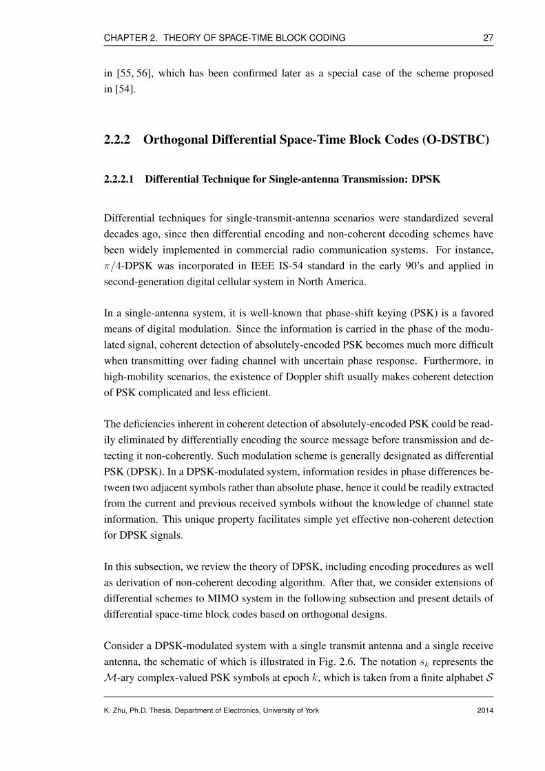
CHAPTER 2. THEORY OF SPACE-TIME BLOCK CODING 27
in [55, 56], which has been confirmed later as a special case of the scheme proposedin [54].
2.2.2 Orthogonal Differential Space-Time Block Codes (O-DSTBC)
2.2.2.1 Differential Technique for Single-antenna Transmission: DPSK
Differential techniques for single-transmit-antenna scenarios were standardized severaldecades ago, since then differential encoding and non-coherent decoding schemes havebeen widely implemented in commercial radio communication systems. For instance,π/4-DPSK was incorporated in IEEE IS-54 standard in the early 90’s and applied insecond-generation digital cellular system in North America.
In a single-antenna system, it is well-known that phase-shift keying (PSK) is a favoredmeans of digital modulation. Since the information is carried in the phase of the modu-lated signal, coherent detection of absolutely-encoded PSK becomes much more difficultwhen transmitting over fading channel with uncertain phase response. Furthermore, inhigh-mobility scenarios, the existence of Doppler shift usually makes coherent detectionof PSK complicated and less efficient.
The deficiencies inherent in coherent detection of absolutely-encoded PSK could be read-ily eliminated by differentially encoding the source message before transmission and de-tecting it non-coherently. Such modulation scheme is generally designated as differentialPSK (DPSK). In a DPSK-modulated system, information resides in phase differences be-tween two adjacent symbols rather than absolute phase, hence it could be readily extractedfrom the current and previous received symbols without the knowledge of channel stateinformation. This unique property facilitates simple yet effective non-coherent detectionfor DPSK signals.
In this subsection, we review the theory of DPSK, including encoding procedures as wellas derivation of non-coherent decoding algorithm. After that, we consider extensions ofdifferential schemes to MIMO system in the following subsection and present details ofdifferential space-time block codes based on orthogonal designs.
Consider a DPSK-modulated system with a single transmit antenna and a single receiveantenna, the schematic of which is illustrated in Fig. 2.6. The notation sk represents theM-ary complex-valued PSK symbols at epoch k, which is taken from a finite alphabet S
K. Zhu, Ph.D. Thesis, Department of Electronics, University of York 2014
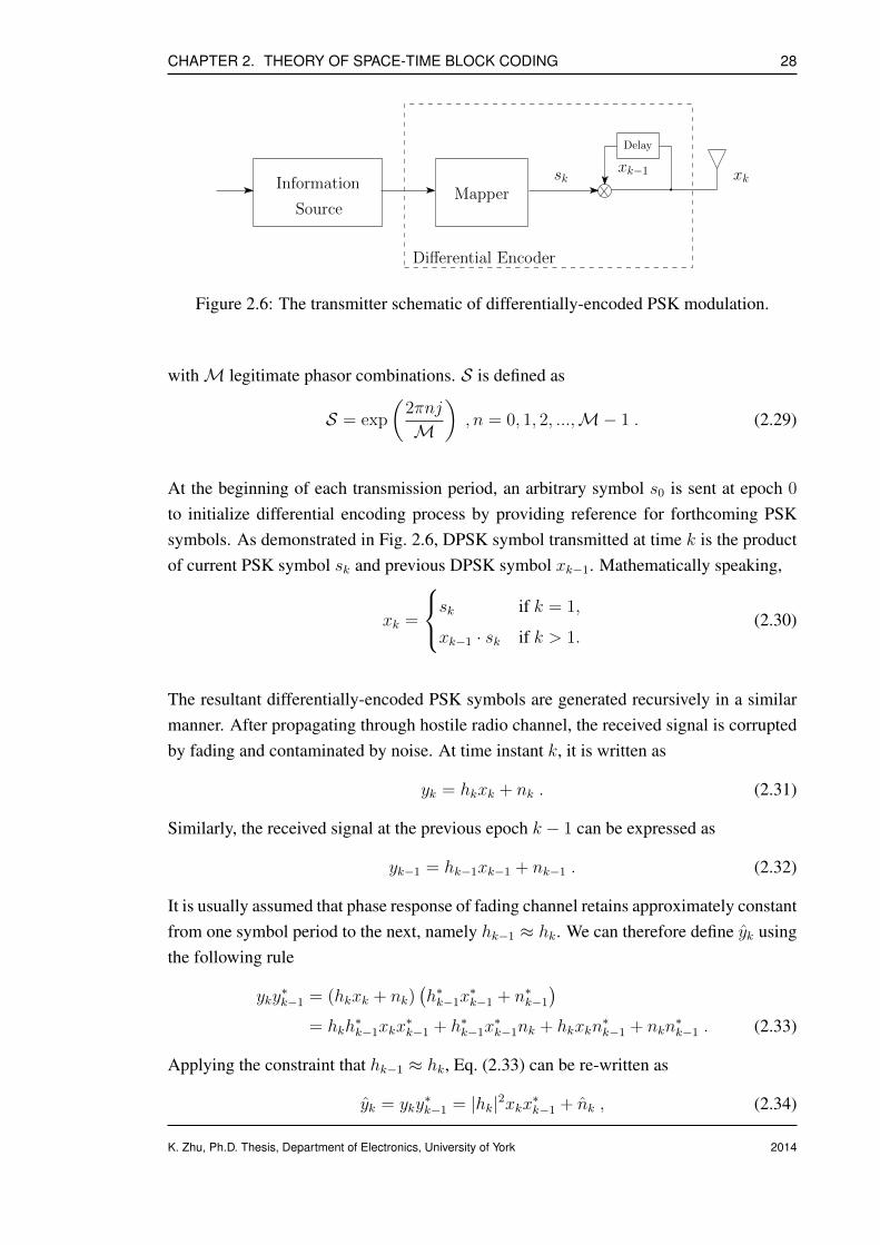
CHAPTER 2. THEORY OF SPACE-TIME BLOCK CODING 28
Information
Source
skMapper
Delay
Differential Encoder
xk−1 xk
Figure 2.6: The transmitter schematic of differentially-encoded PSK modulation.
withM legitimate phasor combinations. S is defined as
S = exp
(2πnj
M
), n = 0, 1, 2, ...,M− 1 . (2.29)
At the beginning of each transmission period, an arbitrary symbol s0 is sent at epoch 0
to initialize differential encoding process by providing reference for forthcoming PSKsymbols. As demonstrated in Fig. 2.6, DPSK symbol transmitted at time k is the productof current PSK symbol sk and previous DPSK symbol xk−1. Mathematically speaking,
xk =
sk if k = 1,
xk−1 · sk if k > 1.(2.30)
The resultant differentially-encoded PSK symbols are generated recursively in a similarmanner. After propagating through hostile radio channel, the received signal is corruptedby fading and contaminated by noise. At time instant k, it is written as
yk = hkxk + nk . (2.31)
Similarly, the received signal at the previous epoch k − 1 can be expressed as
yk−1 = hk−1xk−1 + nk−1 . (2.32)
It is usually assumed that phase response of fading channel retains approximately constantfrom one symbol period to the next, namely hk−1 ≈ hk. We can therefore define yk usingthe following rule
yky∗k−1 = (hkxk + nk)
(h∗k−1x
∗k−1 + n∗k−1
)
= hkh∗k−1xkx
∗k−1 + h∗k−1x
∗k−1nk + hkxkn
∗k−1 + nkn
∗k−1 . (2.33)
Applying the constraint that hk−1 ≈ hk, Eq. (2.33) can be re-written as
yk = yky∗k−1 = |hk|2xkx∗k−1 + nk , (2.34)
K. Zhu, Ph.D. Thesis, Department of Electronics, University of York 2014

CHAPTER 2. THEORY OF SPACE-TIME BLOCK CODING 29
where nk is the equivalent Gaussian noise containing all terms related to original noisenk. Substitute Eq. (2.30) into Eq. (2.34), this yields
yk = yky∗k−1 = |hk|2xk−1x
∗k−1sk + nk . (2.35)
Since all PSK signal points are from unitary constellation with unity energy, in otherwords, xk−1x
∗k−1 = |xk−1|2 = 1, Eq. (2.35) is further simplified into
yk = yky∗k−1 = |hk|2sk + nk . (2.36)
Upon observing Eq. (2.36), the optimal estimate of sk is found using ML algorithm, whichis formulated as
sk = arg minsk∈M−PSK
|yky∗k−1 − |hk|2sk|2 . (2.37)
Note that the term |hk|2 is considered as a scaling factor that does not affect the geometryof the detection regions provided that all PSK constellation points are on the same circle.Hence, the non-coherent detection criterion of minimizing Eq. (2.37) is equivalent tominimizing the following function
sk = arg minsk∈M−PSK
|yky∗k−1 − sk|2 . (2.38)
This implies that optimum non-coherent detection of DPSK signal is to find the hypothesissymbol fromM-ary PSK constellation that is the closet point to yky∗k−1. Observing theequivalent noise term nk, it is clear that energy level of nk is approximately 2|hk|2 timeslarger than that of conventional coherent PSK counterpart. Since average fading poweris normalized to unity, this translates to half of received SNR for differential detectionscheme which leads to 3-dB performance degradation. Non-coherently-detected DPSKscheme no longer requires the availability of channel information for data recovery, theadvantage of DPSK results from trading extra 3-dB transmit energy for exemption ofchannel knowledge.
2.2.2.2 Differential Technique for Multiple-antenna Transmission: ODSTBC
Differential transmission and non-coherent reception scheme for the single-antenna sce-nario is revisited in the last subsection, it is natural to consider extensions to MIMOchannels with similar properties. In this subsection, we primarily concentrate on a sim-ple differential scheme that is originated from classic orthogonal STBC. Differential ap-proaches based on other structures, for example unitary space-time modulation (USTM),will also be presented in general.
K. Zhu, Ph.D. Thesis, Department of Electronics, University of York 2014
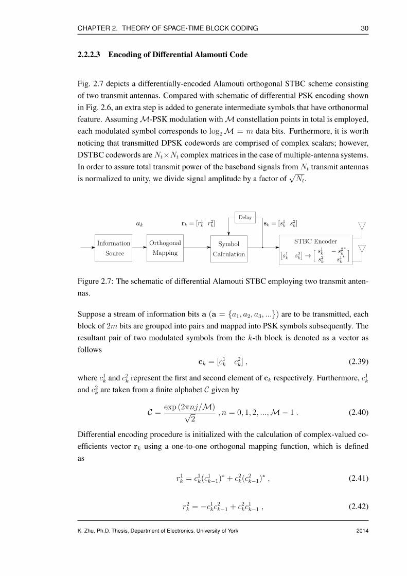
CHAPTER 2. THEORY OF SPACE-TIME BLOCK CODING 30
2.2.2.3 Encoding of Differential Alamouti Code
Fig. 2.7 depicts a differentially-encoded Alamouti orthogonal STBC scheme consistingof two transmit antennas. Compared with schematic of differential PSK encoding shownin Fig. 2.6, an extra step is added to generate intermediate symbols that have orthonormalfeature. AssumingM-PSK modulation withM constellation points in total is employed,each modulated symbol corresponds to log2M = m data bits. Furthermore, it is worthnoticing that transmitted DPSK codewords are comprised of complex scalars; however,DSTBC codewords areNt×Nt complex matrices in the case of multiple-antenna systems.In order to assure total transmit power of the baseband signals from Nt transmit antennasis normalized to unity, we divide signal amplitude by a factor of
√Nt.
Mapping
Orthogonal
ak sk = [s1k s2k]rk = [r1k r2k]
STBC Encoder
[s1k s2k
]→
[ ]s1k − s2k∗
s2k s1k∗
Delay
Symbol
Calculation
Information
Source
Figure 2.7: The schematic of differential Alamouti STBC employing two transmit anten-nas.
Suppose a stream of information bits a (a = a1, a2, a3, ...) are to be transmitted, eachblock of 2m bits are grouped into pairs and mapped into PSK symbols subsequently. Theresultant pair of two modulated symbols from the k-th block is denoted as a vector asfollows
ck = [c1k c2
k] , (2.39)
where c1k and c2
k represent the first and second element of ck respectively. Furthermore, c1k
and c2k are taken from a finite alphabet C given by
C =exp (2πnj/M)√
2, n = 0, 1, 2, ...,M− 1 . (2.40)
Differential encoding procedure is initialized with the calculation of complex-valued co-efficients vector rk using a one-to-one orthogonal mapping function, which is definedas
r1k = c1
k(c1k−1)∗ + c2
k(c2k−1)∗ , (2.41)
r2k = −c1
kc2k−1 + c2
kc1k−1 , (2.42)
K. Zhu, Ph.D. Thesis, Department of Electronics, University of York 2014
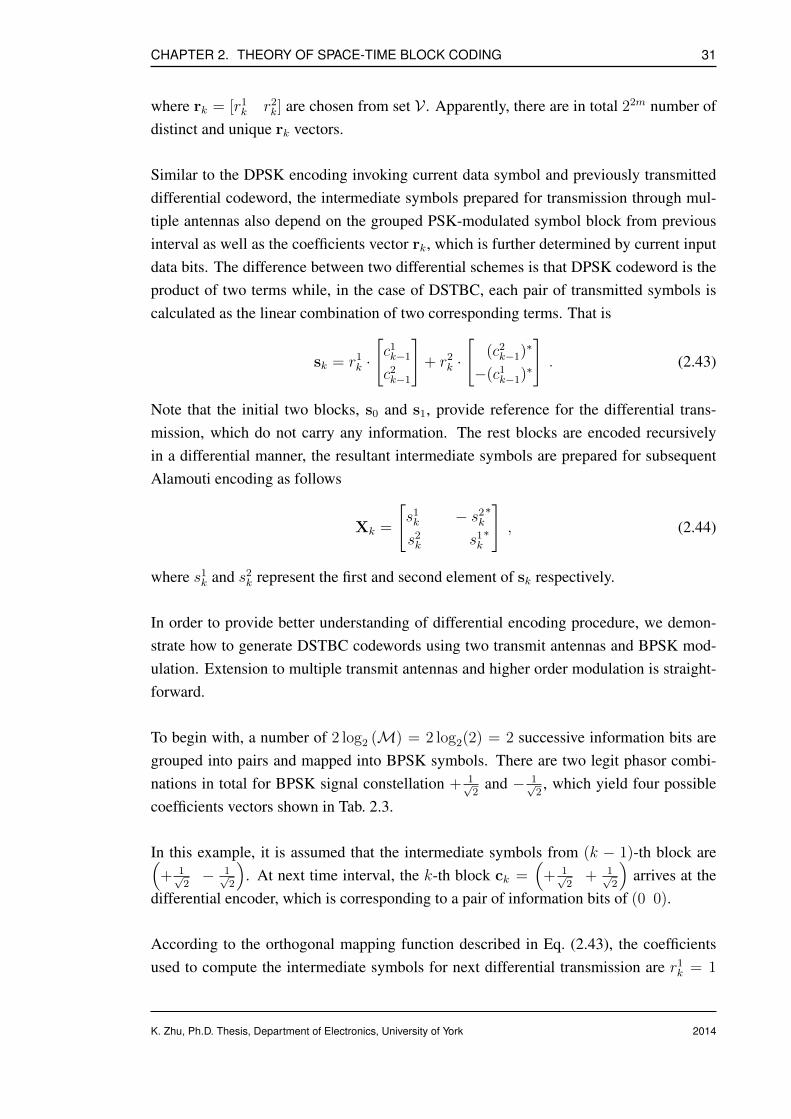
CHAPTER 2. THEORY OF SPACE-TIME BLOCK CODING 31
where rk = [r1k r2
k] are chosen from set V . Apparently, there are in total 22m number ofdistinct and unique rk vectors.
Similar to the DPSK encoding invoking current data symbol and previously transmitteddifferential codeword, the intermediate symbols prepared for transmission through mul-tiple antennas also depend on the grouped PSK-modulated symbol block from previousinterval as well as the coefficients vector rk, which is further determined by current inputdata bits. The difference between two differential schemes is that DPSK codeword is theproduct of two terms while, in the case of DSTBC, each pair of transmitted symbols iscalculated as the linear combination of two corresponding terms. That is
sk = r1k ·[c1k−1
c2k−1
]+ r2
k ·[
(c2k−1)∗
−(c1k−1)∗
]. (2.43)
Note that the initial two blocks, s0 and s1, provide reference for the differential trans-mission, which do not carry any information. The rest blocks are encoded recursivelyin a differential manner, the resultant intermediate symbols are prepared for subsequentAlamouti encoding as follows
Xk =
[s1k − s2
k∗
s2k s1
k∗
], (2.44)
where s1k and s2
k represent the first and second element of sk respectively.
In order to provide better understanding of differential encoding procedure, we demon-strate how to generate DSTBC codewords using two transmit antennas and BPSK mod-ulation. Extension to multiple transmit antennas and higher order modulation is straight-forward.
To begin with, a number of 2 log2 (M) = 2 log2(2) = 2 successive information bits aregrouped into pairs and mapped into BPSK symbols. There are two legit phasor combi-nations in total for BPSK signal constellation + 1√
2and − 1√
2, which yield four possible
coefficients vectors shown in Tab. 2.3.
In this example, it is assumed that the intermediate symbols from (k − 1)-th block are(+ 1√
2− 1√
2
). At next time interval, the k-th block ck =
(+ 1√
2+ 1√
2
)arrives at the
differential encoder, which is corresponding to a pair of information bits of (0 0).
According to the orthogonal mapping function described in Eq. (2.43), the coefficientsused to compute the intermediate symbols for next differential transmission are r1
k = 1
K. Zhu, Ph.D. Thesis, Department of Electronics, University of York 2014

CHAPTER 2. THEORY OF SPACE-TIME BLOCK CODING 32
Table 2.3: Demonstration of computing coefficients vectors for given input data bits.
Input data bits rk = [r1k r2
k]
(0 0) (1 0)(0 1) (0 -1)(1 0) (0 1)(1 1) (-1 0)
and r2k = 0, respectively. Thus, for the k-th block, we have
sk = r1k ·[c1k−1
c2k−1
]+ r2
k ·[
(c2k−1)∗
−(c1k−1)∗
],
= 1 ·[
+ 1√2
− 1√2
]+ 0 ·
[− 1√
2
− 1√2
],
=
[+ 1√
2
− 1√2
]. (2.45)
After Alamouti STBC encoding, + 1√2
and − 1√2
are sent from antenna one and two at thefirst transmission slot, + 1√
2and + 1√
2are sent from antenna one and two at the second
transmission slot, respectively.
Xk =
[s1k − s2
k∗
s2k s1
k∗
],
=
[+ 1√
2+ 1√
2
− 1√2
+ 1√2
]. (2.46)
The relationship between input data bits and intermediate symbols from previous block issummarized in Tab. 2.4.
K. Zhu, Ph.D. Thesis, Department of Electronics, University of York 2014
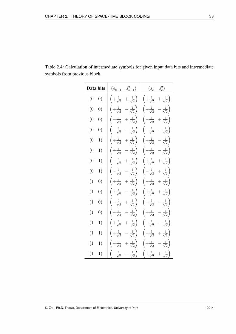
CHAPTER 2. THEORY OF SPACE-TIME BLOCK CODING 33
Table 2.4: Calculation of intermediate symbols for given input data bits and intermediatesymbols from previous block.
Data bits (s1k−1 s2
k−1) (s1k s2
k)
(0 0)(
+ 1√2
+ 1√2
) (+ 1√
2+ 1√
2
)
(0 0)(
+ 1√2− 1√
2
) (+ 1√
2− 1√
2
)
(0 0)(− 1√
2+ 1√
2
) (− 1√
2+ 1√
2
)
(0 0)(− 1√
2− 1√
2
) (− 1√
2− 1√
2
)
(0 1)(
+ 1√2
+ 1√2
) (+ 1√
2− 1√
2
)
(0 1)(
+ 1√2− 1√
2
) (− 1√
2− 1√
2
)
(0 1)(− 1√
2+ 1√
2
) (+ 1√
2+ 1√
2
)
(0 1)(− 1√
2− 1√
2
) (− 1√
2+ 1√
2
)
(1 0)(
+ 1√2
+ 1√2
) (− 1√
2+ 1√
2
)
(1 0)(
+ 1√2− 1√
2
) (+ 1√
2+ 1√
2
)
(1 0)(− 1√
2+ 1√
2
) (− 1√
2− 1√
2
)
(1 0)(− 1√
2− 1√
2
) (+ 1√
2− 1√
2
)
(1 1)(
+ 1√2
+ 1√2
) (− 1√
2− 1√
2
)
(1 1)(
+ 1√2− 1√
2
) (− 1√
2+ 1√
2
)
(1 1)(− 1√
2+ 1√
2
) (+ 1√
2− 1√
2
)
(1 1)(− 1√
2− 1√
2
) (+ 1√
2+ 1√
2
)
K. Zhu, Ph.D. Thesis, Department of Electronics, University of York 2014

CHAPTER 2. THEORY OF SPACE-TIME BLOCK CODING 34
2.2.2.4 Receiver and Non-coherent Decoding
In this subsection, we discuss the decoding algorithm for the differential Alamouti codeusing two transmit antennas. For the sake of simplicity of presentation, the number ofreceive antenna is limited to one. This limitation is lifted later enabling recovery of thetransmitted information employing Nr receive antennas.
ML
Decoding
DecisionMetric
Calculation Mapping
Orthogonal
Inverseyk
yk−1
ak
rk = [r1k r2k]
Delay
Figure 2.8: The receiver schematic of differential Alamouti STBC employing one receiveantenna.
If the notation yik represents the i-th element (i = 1, 2 when Nt = 2) from the k-threceived symbol block, the received symbols for two successive blocks can be expressedas
y1k−1 = s1
k−1h1k−1 + s2
k−1h2k−1 + n1
k−1 , (2.47)
y2k−1 = −(s2
k−1)∗h1k−1 + (s1
k−1)∗h2k−1 + n2
k−1 , (2.48)
y1k = s1
kh1k + s2
kh2k + n1
k , (2.49)
y2k = −(s2
k)∗h1
k + (s1k)∗h2
k + n2k , (2.50)
where hik is the Rayleigh fading coefficient experienced by the i-th element of the k-thblock. Under the assumption of quasi-static fading, channel coefficients appear almostconstant for consecutive blocks, h1
k−1 ≈ h1k = h1 and h2
k−1 ≈ h2k = h2. Moreover, nik
denotes the Gaussian noise added to the i-th element of the k-th block, which has zeromean and variance of 1/N0 per dimension.
For the ease of illustration, we further define the vector representations of the receivedsignals as follows
(y1k−1 (y2
k−1)∗)
=(s1k−1 s2
k−1
)(h1 h∗2h2 − h∗1
)
︸ ︷︷ ︸H
+(n1k−1 (n2
k−1)∗)
︸ ︷︷ ︸N 1k−1
. (2.51)
K. Zhu, Ph.D. Thesis, Department of Electronics, University of York 2014

CHAPTER 2. THEORY OF SPACE-TIME BLOCK CODING 35
Similarly,
(y2k−1 − (y1
k−1)∗)
=(−(s2
k−1)∗ (s1k−1)∗
)(h1 h∗2h2 − h∗1
)
︸ ︷︷ ︸H
+(n2k−1 − (n1
k−1)∗)
︸ ︷︷ ︸N 2k−1
,
(2.52)(y1k (y2
k)∗) =
(s1k s2
k
)(h1 h∗2h2 − h∗1
)
︸ ︷︷ ︸H
+(n1k−1 (n2
k−1)∗)
︸ ︷︷ ︸N 1k
. (2.53)
Construction of the decision statistics is based on the inner product of two adjacent re-ceived symbol blocks given in Eq. (2.51) and Eq. (2.53).
(y1k (y2
k)∗) ·(y1k−1) (y2
k−1)∗)
= y1k(y
1k−1)∗ + (y2
k)∗y2k−1 ,
=(s1k s2
k
)HH†
(s1k−1 s2
k−1
)∗+
(s1k s2
k
)H(N 1
k−1)∗ +N 1kH†
(s1k−1 s2
k−1
)∗+N 1
k (N 1k−1)∗︸ ︷︷ ︸
N1
,
(2.54)
r1k =
(|h1|2 + |h2|2
) (s1k(s
1k−1)∗ + s2
k(s2k−1)∗
)+ N1 . (2.55)
Similarly
(y1k (y2
k)∗) ·(y2k−1) − (y1
k−1)∗)
= y1k(y
2k−1)∗ − (y2
k)∗y1k−1 ,
=(s1k s2
k
)HH†
(−s2
k−1 s1k−1
)∗+
(s1k s2
k
)H(N 2
k−1)∗ +N 1kH†
(−s2
k−1 s1k−1
)∗+N 1
k (N 2k−1)∗︸ ︷︷ ︸
N2
(2.56)
r2k =
(|h1|2 + |h2|2
) (−s1
ks2k−1 + s2
ks1k−1
)+ N2 . (2.57)
Summarize Eq. (2.55) and Eq. (2.57), we can write the decision statistics in a vector form
(r1k r2
k
)=(|h1|2 + |h2|2
) (r1k r2
k
)+(N1 N2
). (2.58)
For a given channel realization h1 and h2, the decision statistics r1 and r2 only dependon the differential coefficients r1 and r2, respectively. Since all the coefficients vectors inthe set V have equal lengths, the receiver now chooses the closest coefficient vector fromV to the decision statistics signal vector (r1, r2) as the decoding output. Then the inversemapping of Eq. (2.41) and Eq. (2.42) is applied to recover the transmitted block of bits.
K. Zhu, Ph.D. Thesis, Department of Electronics, University of York 2014
CHAPTER 2. THEORY OF SPACE-TIME BLOCK CODING 36
2.2.2.5 Decoding with Multiple Receive Antennas
In this subsection, we extend the concept of non-coherent DSTBC reception to supportmultiple receive antennas, which could in return benefit from higher level of diversity. Thedifferential encoding and transmission arrangement are identical to the case of employinga single receive antenna; however, the combining and diversity reception algorithm on thereceiving side are different.
To begin with, transmitted DSTBC symbols picked up by the j-th receive antenna duringtwo successive symbol intervals (k − 1)-th and k-th are denoted as follows
y1j,k−1 = s1
k−1h1j,k−1 + s2
k−1h2j,k−1 + n1
j,k−1 , (2.59)
y2j,k−1 = −(s2
k−1)∗h1j,k−1 + (s1
k−1)∗h2j,k−1 + n2
j,k−1 , (2.60)
y1j,k = s1
kh1j,k + s2
kh2j,k + n1
j,k , (2.61)
y2j,k = −(s2
k)∗h1
j,k + (s1k)∗h2
j,k + n2j,k , (2.62)
where hij,k (i = 1, 2; j = 1, 2, ..., Nr) is the notation for the complex-valued Rayleighfading coefficients of the channel between the i-th transmit antenna and the j-th receiveantenna experienced by the k-th symbol block; while nij,k represents the AWGN added tothe k-th symbol block at the j-th receiver.
Since the quasi-static channel model is assumed for DSTBC transmission, hij,k could bereplaced with hj,i in the rest of this subsection to keep the presentation concise. Followingthe same steps formulated in Eq. (2.51)-Eq. (2.57), two decision metrics correspond to thej-th receiver are written as
r1j,k =
(|hj,1|2 + |hj,2|2
) (s1k(s
1k−1)∗ + s2
k(s2k−1)∗
)+ Nj,1 , (2.63)
r2j,k =
(|hj,1|2 + |hj,2|2
) (−s1
ks2k−1 + s2
ks1k−1
)+ Nj,2 . (2.64)
Summarize Eq. (2.63) and Eq. (2.64), the final decision statistics are now adapted to
(r1k r2
k
)=
(Nr∑
j=1
(|hj,1|2 + |hj,2|2
))(r1k r2
k
)+
Nr∑
j=1
(Nj,1 Nj,2
). (2.65)
K. Zhu, Ph.D. Thesis, Department of Electronics, University of York 2014

CHAPTER 2. THEORY OF SPACE-TIME BLOCK CODING 37
2.2.2.6 Performance Evaluation of Differential STBC Scheme
In this subsection, we present some simulation results of the differential STBC intro-duced previously. It is assumed that Nt = 2 antennas are used in the transmitting side,we focus on the bit error performance for scenarios with different numbers of receive an-tennas Nr = 1, 2, 4. Since various kinds of differential STBCs are derived from classicAlamouti code, the terms ‘differential STBC’ and ‘differential Alamouti code’ are usedinterchangeably.
The following simulation results are based on the quasi-static flat Rayleigh-fading channelmodel. This implies that the path gains of the fading channel, which are independent com-plex Gaussian random variables, remain constant during the transmission of one frame.We also provide the simulation results for corresponding coherent Alamouti code withexactly the same configurations as comparison benchmarks.
Fig. 2.9 plots the BER versus transmitted Eb/N0 when BPSK-modulated symbols areemitted from two transmit antennas in two successive transmission periods, the overalltransmission rate is therefore equivalent to 1 bit/sec/Hz. As denoted by red solid-lineand black dashed-line in Fig. 2.9, the BER curves corresponding to orthogonal AlamoutiSTBC and the differential one share the same slope indicating that differential Alamouticode is also capable of performing at full diversity order, albeit this is achieved at the costof approximately 3.0 dB degradation due to the doubled noise variance incurred duringnon-coherent decoding. It is natural to find such observation is consistent with systemsemploying differential PSK at the transmitter, since differential Alamouti STBC is infact an extension of DPSK to multiple-antenna scenarios. It is illustrated in Fig. 2.9 thatsignificant performance improvement of roughly 10.5 dB is attained at BER of 10−5 fromincorporating an extra antenna in the receiving side, while a further reduction of about6.50 dB transmit power is witnessed with two additional receive antennas.
It is worth noticing that the assumption of constant path gains during transmission of en-tire frame is somewhat unrealistic, however, an irreducible error floor is incurred whensuch assumption is not satisfied. For the purpose of eliminating the underlying assump-tion, a variety of solutions are contrived in literature, where using more than two receivedsymbol blocks to facilitate the detection seems perform effectively and efficiently. Formore detailed discussion, one can refer to [57] and reference therein.
Fig. 2.10 and Fig. 2.11 depict the comparison of BER versus Eb/N0 performance for asimilarly-configured differential STBC scheme with transmission rate of 2 bits/sec/Hz,which is achieved by utilizing Gray- and SP-mapped QPSK symbols for two successive
K. Zhu, Ph.D. Thesis, Department of Electronics, University of York 2014

CHAPTER 2. THEORY OF SPACE-TIME BLOCK CODING 38
transmission periods, respectively. Full diversity order is also observed in these figures.When aiming at a bit error probability of 10−5, an additional SNR of 3.0 dB is requiredfor systems invoking Nr = 1, 2, 4 receiving antennas in comparison to 1 bits/sec/Hz case.As expected, for SP-mapped scheme, the performance is slightly degraded by about 1.0∼ 2.0 dB at BER = 10−5. Fig. 2.12 and Fig. 2.13 provide similar results for differentialAlamouti scheme transmitting at 3 bits/sec/Hz under the same simulation conditions. Theresulting differential scheme, which also has the ability to acquire full spatial diversitygain, is 35.0− 27.0 = 8.0 dB and 35.0− 30.0 = 5.0 dB inferior in terms of the requiredSNR compared to the 1 bit/sec/Hz and 2 bits/sec/Hz at BER = 10−5, respectively.
According to the results presented in Fig. 2.9-Fig. 2.14, differential Alamouti codes ex-hibit many desirable properties, including straightforward and simple encoding, full spa-tial diversity gain, non-coherent decoding dispensing with channel information at thereceiver. However, on the other hand, the construction procedure of differential Alam-outi codes imposes limitations. For instance, when aiming at transmission rate of 2bits/sec/Hz, QPSK-modulated symbols are invoked to compute the intermediate sym-bol set sk following Eq. (2.41)-Eq. (2.43) defined in subsection 2.2.2.3. Note that theaforementioned encoding procedure significantly expands the signal constellation fornon-binary signalling. As a consequence, the resulting intermediate symbols are takenfrom an irregular 9QAM constellation with more than four points instead of QPSK con-stellation. This translates to some inconvenience for incorporating differential AlamoutiSTBC in existing communication systems.
Some results for USTM schemes based on group codes are considered in order to providea comprehensive comparison between distinct differential techniques. For instance, thebit error performance of unity-rate as well as 3/2-rate USTM employing Nt = 2 trans-mit antennas as well as Nr receive antennas (Nr = 1, 2, 4) are shown in Fig. 2.14 andFig. 2.15, respectively. It is clearly shown that the unique feature of USTM schemes alsoenable non-coherent detection in the receiver without the knowledge of channel coeffi-cients. Furthermore, USTM is capable of performing as well as the differential Alam-outi codes. Note that USTM schemes generally suffer from rate deficiency. To elabo-rate further, according to encoding rule of USTM, the overall coding rate is defined aslog2(2 ∗ 22)/Nt = log2(2 ∗ 22)/2 = 1.5 bits/sec/Hz, which leads to a lower coding rate incomparison to differential Alamouti STBC.
K. Zhu, Ph.D. Thesis, Department of Electronics, University of York 2014
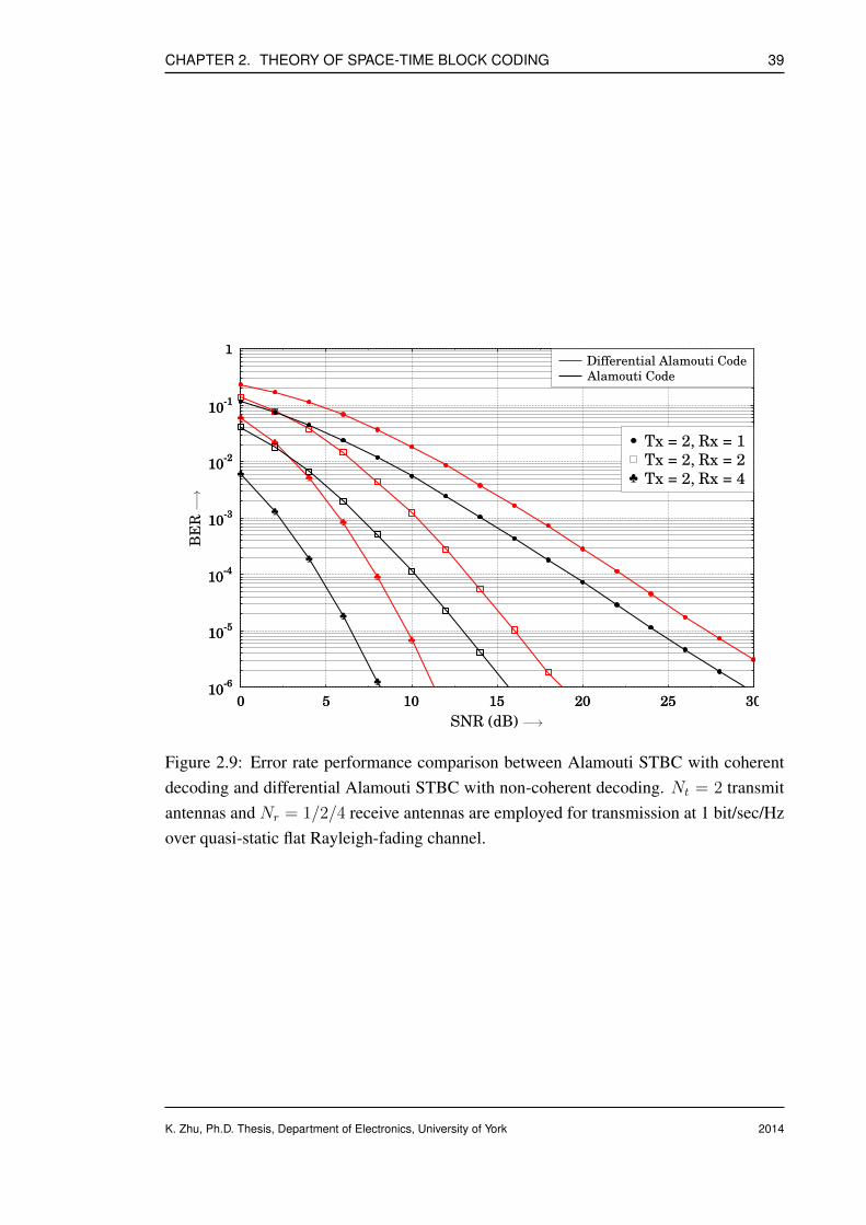
CHAPTER 2. THEORY OF SPACE-TIME BLOCK CODING 39
10-6
10-5
10-4
10-3
10-2
10-1
1
0 5 10 15 20 25 30
♣
♣
♣
♣
♣
♣
♣
♣
♣
♣
♣
10-6
10-5
10-4
10-3
10-2
10-1
1
BER
0 5 10 15 20 25 30
SNR (dB)
Differential Alamouti Code
Alamouti Code
Tx = 2, Rx = 1
Tx = 2, Rx = 2♣ Tx = 2, Rx = 4
−→
−→
Figure 2.9: Error rate performance comparison between Alamouti STBC with coherentdecoding and differential Alamouti STBC with non-coherent decoding. Nt = 2 transmitantennas and Nr = 1/2/4 receive antennas are employed for transmission at 1 bit/sec/Hzover quasi-static flat Rayleigh-fading channel.
K. Zhu, Ph.D. Thesis, Department of Electronics, University of York 2014
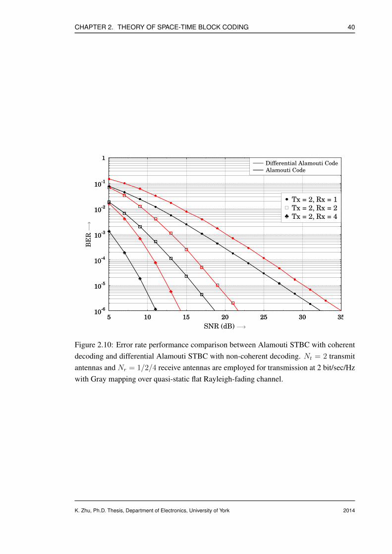
CHAPTER 2. THEORY OF SPACE-TIME BLOCK CODING 40
10-6
10-5
10-4
10-3
10-2
10-1
1
5 10 15 20 25 30 35
♣
♣
♣
♣
♣
♣
♣
♣
♣10
-6
10-5
10-4
10-3
10-2
10-1
1
BER
5 10 15 20 25 30 35
SNR (dB)
Differential Alamouti Code
Alamouti Code
Tx = 2, Rx = 1
Tx = 2, Rx = 2♣ Tx = 2, Rx = 4
−→
−→
Figure 2.10: Error rate performance comparison between Alamouti STBC with coherentdecoding and differential Alamouti STBC with non-coherent decoding. Nt = 2 transmitantennas and Nr = 1/2/4 receive antennas are employed for transmission at 2 bit/sec/Hzwith Gray mapping over quasi-static flat Rayleigh-fading channel.
K. Zhu, Ph.D. Thesis, Department of Electronics, University of York 2014

CHAPTER 2. THEORY OF SPACE-TIME BLOCK CODING 41
10-6
10-5
10-4
10-3
10-2
10-1
1
5 10 15 20 25 30 35
♣
♣
♣
♣
♣
♣
♣
♣
♣
10-6
10-5
10-4
10-3
10-2
10-1
1
BER
5 10 15 20 25 30 35
SNR (dB)
Differential Alamouti Code
Alamouti Code
Tx = 2, Rx = 1
Tx = 2, Rx = 2♣ Tx = 2, Rx = 4
−→
−→
Figure 2.11: Error rate performance comparison between Alamouti STBC with coherentdecoding and differential Alamouti STBC with non-coherent decoding. Nt = 2 transmitantennas and Nr = 1/2/4 receive antennas are employed for transmission at 2 bit/sec/Hzwith SP mapping over quasi-static flat Rayleigh-fading channel.
K. Zhu, Ph.D. Thesis, Department of Electronics, University of York 2014

CHAPTER 2. THEORY OF SPACE-TIME BLOCK CODING 42
10-6
10-5
10-4
10-3
10-2
10-1
1
5 10 15 20 25 30 35 40
♣
♣
♣
♣
♣
♣
♣
♣
♣
♣
♣
♣
10-6
10-5
10-4
10-3
10-2
10-1
1
BER
5 10 15 20 25 30 35 40
SNR (dB)
Differential Alamouti Code
Alamouti Code
Tx = 2, Rx = 1
Tx = 2, Rx = 2♣ Tx = 2, Rx = 4
−→
−→
Figure 2.12: Error rate performance comparison between Alamouti STBC with coherentdecoding and differential Alamouti STBC with non-coherent decoding. Nt = 2 transmitantennas and Nr = 1/2/4 receive antennas are employed for transmission at 3 bit/sec/Hzwith Gray mapping over quasi-static flat Rayleigh-fading channel.
K. Zhu, Ph.D. Thesis, Department of Electronics, University of York 2014

CHAPTER 2. THEORY OF SPACE-TIME BLOCK CODING 43
10-6
10-5
10-4
10-3
10-2
10-1
1
5 10 15 20 25 30 35 40
♣
♣
♣
♣
♣
♣
♣
♣
♣
♣
♣
♣
10-6
10-5
10-4
10-3
10-2
10-1
1
BER
5 10 15 20 25 30 35 40
SNR (dB)
Differential Alamouti Code
Alamouti Code
Tx = 2, Rx = 1
Tx = 2, Rx = 2♣ Tx = 2, Rx = 4
−→
−→
Figure 2.13: Error rate performance comparison between Alamouti STBC with coherentdecoding and differential Alamouti STBC with non-coherent decoding. Nt = 2 transmitantennas and Nr = 1/2/4 receive antennas are employed for transmission at 3 bit/sec/Hzwith SP mapping over quasi-static flat Rayleigh-fading channel.
K. Zhu, Ph.D. Thesis, Department of Electronics, University of York 2014
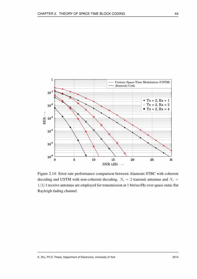
CHAPTER 2. THEORY OF SPACE-TIME BLOCK CODING 44
10-6
10-5
10-4
10-3
10-2
10-1
1
0 5 10 15 20 25 30
♣
♣
♣
♣
♣
♣
♣
♣
♣
♣
♣
10-6
10-5
10-4
10-3
10-2
10-1
1
BER
0 5 10 15 20 25 30
SNR (dB)
Unitary Space-Time Modulation (USTM)
Alamouti Code
Tx = 2, Rx = 1
Tx = 2, Rx = 2♣ Tx = 2, Rx = 4
−→
−→
Figure 2.14: Error rate performance comparison between Alamouti STBC with coherentdecoding and USTM with non-coherent decoding. Nt = 2 transmit antennas and Nr =
1/2/4 receive antennas are employed for transmission at 1 bit/sec/Hz over quasi-static flatRayleigh-fading channel.
K. Zhu, Ph.D. Thesis, Department of Electronics, University of York 2014

CHAPTER 2. THEORY OF SPACE-TIME BLOCK CODING 45
10-6
10-5
10-4
10-3
10-2
10-1
1
5 10 15 20 25 30 35
♣
♣
♣
♣
♣
♣
♣
♣10
-6
10-5
10-4
10-3
10-2
10-1
1
BER
5 10 15 20 25 30 35
SNR (dB)
Unitary Space-Time Modulation (USTM)
Alamouti Code
Tx = 2, Rx = 1
Tx = 2, Rx = 2♣ Tx = 2, Rx = 4
−→
−→
Figure 2.15: Error rate performance comparison between Alamouti STBC with coher-ent decoding and USTM with non-coherent decoding. Nt = 2 transmit antennas andNr = 1/2/4 receive antennas are employed for transmission at 1.5 bit/sec/Hz with Graymapping over quasi-static flat Rayleigh-fading channel.
K. Zhu, Ph.D. Thesis, Department of Electronics, University of York 2014
CHAPTER 2. THEORY OF SPACE-TIME BLOCK CODING 46
2.3 Conclusion
In this literature review chapter, some basic principles of space-time coding as well asdifferential space-time coding are revisited and reviewed. Discussions in this chapterinvolve the following aspects
• General introduction of various types of diversity and multiplexing techniques, in-cluding orthogonal space-time block code, layered space-time code as well as lineardispersion code are given. Desirable properties and features of each scheme are ex-plored and studied.
• The simplest orthogonal space-time block code with two transmit antennas, Alam-outi code, is discussed in detail. Alamouti STBC encoding procedure is first pre-sented, then explanation of non-coherent decoding algorithm starts with single re-ceive antenna and later extends to multiple receive antennas. Performance resultsof the Alamouti STBC are also provided and compared.
• Differential space-time coding is originated from classic space-time coding buteliminating the channel estimation component, hence it is more appealing in prac-tice due to the simplicity of implementation. Similarity and difference between thedifferential unitary space-time modulation and orthogonal differential STBC areinvestigated and discussed.
• Examples of differential encoding and non-coherent decoding techniques are pro-vided for single-antenna as well as multiple-antenna scenarios in the rest part ofChapter 2. Similarly, performance evaluations are also demonstrated.
K. Zhu, Ph.D. Thesis, Department of Electronics, University of York 2014
Chapter 3
Cooperative Space-Time Block Codes
Contents3.1 Cooperative Communication and Relaying . . . . . . . . . . . . . . 47
3.2 Cooperative Space-Time Block Codes for Bidirectional Relaying . . 53
3.3 Numerical Analysis of Distributed STBC aided Two-way RelayingSystem . . . . . . . . . . . . . . . . . . . . . . . . . . . . . . . . . . 66
3.4 Conclusion . . . . . . . . . . . . . . . . . . . . . . . . . . . . . . . . 73
3.1 Cooperative Communication and Relaying
As discussed in Chapter 1, at present, the demand for mobile multimedia services is ex-ploding at an exponential rate. In addition, the energy consumed to support the networksdelivering this kind of high-data-rate services is continuously rising. To create a state-of-the-art broadband wireless communication network, the main focus needs to be shiftedto a new paradigm which could not only meet the increasing demand for data through-put but also reduce the energy consumption. Multiple-input and multiple-output (MIMO)system provides a good solution to meet these requirements by employing multiple trans-mit/receive antennas. In the last decade, we have tasted many benefits of MIMO systems,such as substantial increases in the channel capacity as well as high transmit/receive di-versity gain [9, 13, 14].
However, a practical problem arises when implementing MIMO systems. It is difficult
K. Zhu, Ph.D. Thesis, Department of Electronics, University of York
472014
CHAPTER 3. COOPERATIVE SPACE-TIME BLOCK CODES 48
to integrate more than one antenna in a mobile handset or wireless node (in the contextof wireless sensor network (WSN)) due to stringent limitation imposed on the availablepower and hardware complexity. Most importantly, it is difficult to eliminate the cor-relations between the received signals, which arrive at the antennas simultaneously viadifferent propagation paths, when multiple antennas are deployed in a size-limited mo-bile handset. This makes the recovery of the original signal almost impossible; hence,system performance will be highly degraded.
Under such circumstances, user cooperation or cooperative communication [58–64],which introduces a large number of low-power nodes/users to cooperate and relay sig-nals for others, is a promising approach to balance the tradeoff between high networkthroughput and energy conservation. Furthermore, by creating a virtual antenna array(VAA), where each mobile unit is capable of collaborating with one partner or a few part-ners, cooperative communication has the potential for increasing the achievable capacity,spectrum efficiency, coverage area and quality of experience.
Considering these attractive benefits and the trend of future generation radio networks, anincreasing number of researchers are endeavoring to develop and establish novel multi-hop cooperative wireless networks. More explicitly, optimization of distributed coding,joint channel and network coding design, development of new relaying protocols andcooperative transmission schemes, resource and power allocations, and cross-layer opti-mization are key issues in the design of cooperative wireless networks. Much ongoing re-search on cooperative communication and relaying techniques involving the deploymentof fixed or nomadic relay nodes reveals a bright future of cooperative communications.In 2009, the IEEE standard 802.16j was approved by IEEE-SA Standards Board as anamendment to IEEE standard 802.16-2009.
Based on the behaviour of relaying terminals, the cooperative protocols can be generallyclassified as transparent relaying and regenerative relaying [65]. The former basicallyimplies that the transformations of received signals in the relay nodes simply take placein the analog domain. For instance, the well-known amplify-and-forward (AF) scheme,which only amplifies the signal amplitude before forwarding to the destination nodes, isa typical representative of transparent relaying strategy. On the other hand, in the latterscenario, the received signals in relay nodes are processed in the digital domain resultingin the waveform and information are totally changed. A popular approach called decode-and-forward (DF) falls into this category.
K. Zhu, Ph.D. Thesis, Department of Electronics, University of York 2014
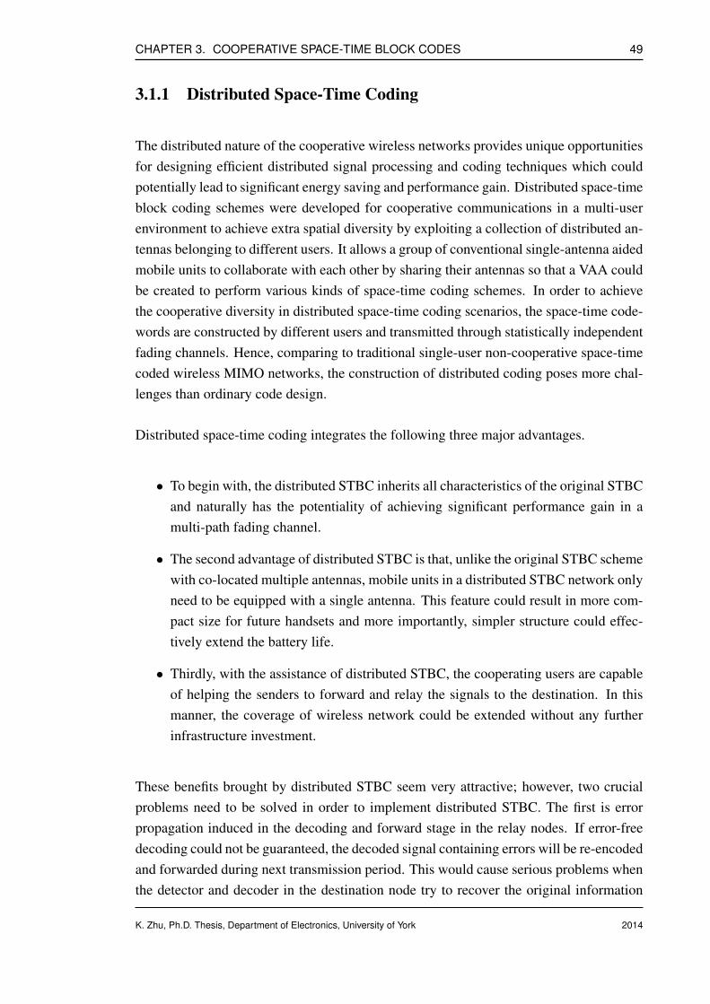
CHAPTER 3. COOPERATIVE SPACE-TIME BLOCK CODES 49
3.1.1 Distributed Space-Time Coding
The distributed nature of the cooperative wireless networks provides unique opportunitiesfor designing efficient distributed signal processing and coding techniques which couldpotentially lead to significant energy saving and performance gain. Distributed space-timeblock coding schemes were developed for cooperative communications in a multi-userenvironment to achieve extra spatial diversity by exploiting a collection of distributed an-tennas belonging to different users. It allows a group of conventional single-antenna aidedmobile units to collaborate with each other by sharing their antennas so that a VAA couldbe created to perform various kinds of space-time coding schemes. In order to achievethe cooperative diversity in distributed space-time coding scenarios, the space-time code-words are constructed by different users and transmitted through statistically independentfading channels. Hence, comparing to traditional single-user non-cooperative space-timecoded wireless MIMO networks, the construction of distributed coding poses more chal-lenges than ordinary code design.
Distributed space-time coding integrates the following three major advantages.
• To begin with, the distributed STBC inherits all characteristics of the original STBCand naturally has the potentiality of achieving significant performance gain in amulti-path fading channel.
• The second advantage of distributed STBC is that, unlike the original STBC schemewith co-located multiple antennas, mobile units in a distributed STBC network onlyneed to be equipped with a single antenna. This feature could result in more com-pact size for future handsets and more importantly, simpler structure could effec-tively extend the battery life.
• Thirdly, with the assistance of distributed STBC, the cooperating users are capableof helping the senders to forward and relay the signals to the destination. In thismanner, the coverage of wireless network could be extended without any furtherinfrastructure investment.
These benefits brought by distributed STBC seem very attractive; however, two crucialproblems need to be solved in order to implement distributed STBC. The first is errorpropagation induced in the decoding and forward stage in the relay nodes. If error-freedecoding could not be guaranteed, the decoded signal containing errors will be re-encodedand forwarded during next transmission period. This would cause serious problems whenthe detector and decoder in the destination node try to recover the original information
K. Zhu, Ph.D. Thesis, Department of Electronics, University of York 2014

CHAPTER 3. COOPERATIVE SPACE-TIME BLOCK CODES 50
and lead to severe degradation of the system performance. It is shown in [66, 67] that theorthogonality of the distributed space-time coded signals constructed and transmitted bymultiple relay nodes in a distributed manner is not preserved due to the error propagationexperienced by the relay-to-destination link. The second key issue needs to be addressedis the synchronization problem among all the collaborative relaying users, which is alsoreferred to as inter-relay-node synchronization. If the destination node picks up severalsignals from different users without sufficient synchronization, it is extremely difficult toperform an accurate decision.
Although both have N independent transmission routes from the transmitter to receiver,two distinct differences between the relaying network having N number of relay nodesand conventional multi-antenna system with N co-located transmit antennas and one re-ceive antenna make them have their unique characteristics. To begin with, in a conven-tional multi-antenna system, antennas are connected by cables enabling full cooperation.However, in the context of a distributed relaying network, they could only coordinate ina distributed fashion since antennas belonging to different users are geographically sepa-rated. Secondly, the destination node is always able to exploit full spatial diversity gainusing conventional co-located STBC schemes; however, for decode-and-forward relayingscenarios, this argument is no longer satisfied as construction of valid distributed STBCcodewords requires each relay node performs error-free recovery of the transmitted in-formation symbols. In fact, the signals observed by the relay nodes are noisy version ofthe transmitted ones, the integrity of estimates recovered from these noisy signals is notguaranteed. In this case, the destination could not attain any spatial diversity gain fromthe employment of distributed STBC.
There are many existing works related to the topic of distributed STBC, for example,in [68], the authors proposed a distributed linear dispersion (DLD) code aided multi-relaycooperative communication system. When the AF protocol is employed, the relay node isonly required to re-encode the received signal with DLD code and transmit the resultantDLD signal to the destination node. If we use the notation Nrelay to represent the totalnumber of relay nodes in the network topology, when the relays have the knowledge ofthe channels between source and relay nodes hsr and the channels between relay and des-tination node hrd, the capacity varies as a function of log(Nrelay) and the power efficiencyvaries as
√Nrelay. The work of [69] is also heuristic, in which two terminals focus on the
exchange of Alamouti space-time coded information symbols simultaneously via a singlepartner with the aid of PLNC, which has the constraint that the source nodes have to beequipped with multiple co-located antennas to avoid inducing error propagation in therelaying process. Other cooperative strategies for two-way relaying schemes, includingthe denoise-and-forward method [70], also achieve the maximum diversity gain offered
K. Zhu, Ph.D. Thesis, Department of Electronics, University of York 2014

CHAPTER 3. COOPERATIVE SPACE-TIME BLOCK CODES 51
by the fading channel.
3.1.2 Two-way Relay Channel and Existing Two-way RelayingStrategies
The direction of signal flow in conventional cooperation schemes is generally consideredas one-way mode. To be more specific, the relay nodes receive the incoming signals fromthe source nodes, which are subsequently amplified or decoded/re-encoded and finallyforwarded to the destination nodes. The hardware used in all relaying nodes is designedunder an important assumption that the transmission and reception of radio signals are notallowed at the same time. In other words, they operate in time-division half-duplex. Thiskind of unidirectional cooperative communication system usually suffers from spectralefficiency loss.
The two-way communication channel was first introduced in the early 1960s. The prop-erty and capacity bound of two-way communication channel were fully investigated andcalculated in [71]. After that, there was not much progress or significant breakthroughin the field of two-way communication until the advent of network coding (NC) [72–75].Network coding was originally proposed to save the bandwidth and increase the networkthroughput for multiple access channels. Network coding arithmetic, which exploits thebroadcast nature of mobile radio channels, is carried out at the bit level after the receivedsignals have been separately detected and decoded in the relay nodes.
Recently, the unidirectional-relay assisted cooperative communication strategies havebeen extended to transmit over two-way relay channels [76]. The schematic of a clas-sic three-node two-way cooperative communication system is shown below.
Figure 3.1: Schematic of a two-way cooperative communication system.
Node A and node B are ordinary time-division half-duplex wireless terminals, which in-tend to simultaneously exchange information with the assistance of a cooperating relaynode R. Each terminal node A or node B acts as a source node as well as a destination
K. Zhu, Ph.D. Thesis, Department of Electronics, University of York 2014

CHAPTER 3. COOPERATIVE SPACE-TIME BLOCK CODES 52
node. As the name suggests, the two-way relaying network takes advantage of the bidirec-tionality of radio channels to overcome the bandwidth inefficiency problem experiencedin one-way relaying case. It is proven in [76] from the viewpoint of information theorythat the spectral efficiency of two-way relaying system is significantly higher than that ofone-way counterpart.
Recall the two-way communication system illustrated in Fig. 3.1. In general, existingtwo-way relaying protocols can be classified into two major categories based on the timeslots needed to complete the information exchange process between two nodes.
The first approach is referred to as the conventional ‘physical-layer’ two-way relayingprotocol. It is the simplest and most straightforward approach to exchange data betweentwo terminals. A vivid illustration of this method is depicted in Fig. 3.2 below. During thefirst and second time slot, node A transmits to relay R and then R forwards the signal tonode B. Subsequently, node B sends the signal to relay R and R relays it to destinationA. Therefore, the total number of transmission slots is four.
Figure 3.2: Illustration of a two-way cooperative communication system using four timeslots.
The number of steps could be reduced to three if the network coding is employed to assistthe information exchange between node A and node B as shown in Fig. 3.3. The firststep is similar to the previous case. The difference is that the relay node R will keep thesignal from node A in its buffer before it is ready to receive signals from other users. Inthe second time slot, node B transmits to relay R and R also save the data into its buffer.Next, R performs the network coding to calculate the bit-wise exclusive or of two datastreams and then forwards the product to node A and B simultaneously. While the overall
K. Zhu, Ph.D. Thesis, Department of Electronics, University of York 2014
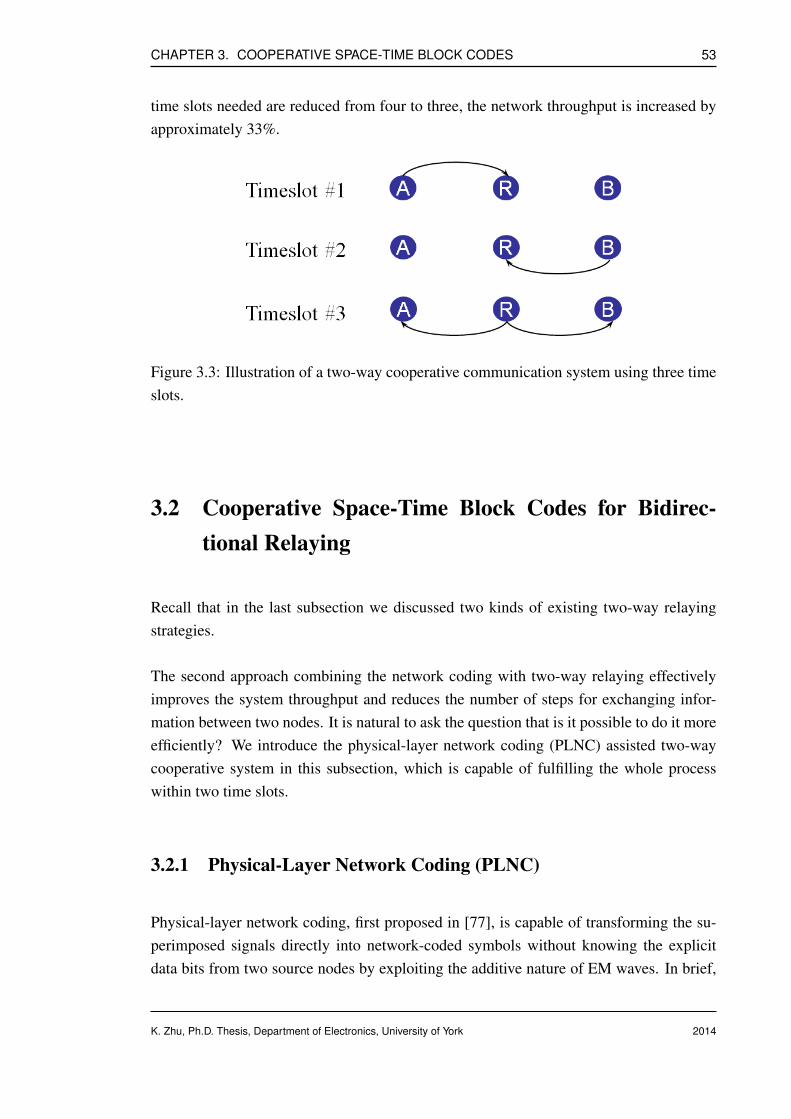
CHAPTER 3. COOPERATIVE SPACE-TIME BLOCK CODES 53
time slots needed are reduced from four to three, the network throughput is increased byapproximately 33%.
Figure 3.3: Illustration of a two-way cooperative communication system using three timeslots.
3.2 Cooperative Space-Time Block Codes for Bidirec-tional Relaying
Recall that in the last subsection we discussed two kinds of existing two-way relayingstrategies.
The second approach combining the network coding with two-way relaying effectivelyimproves the system throughput and reduces the number of steps for exchanging infor-mation between two nodes. It is natural to ask the question that is it possible to do it moreefficiently? We introduce the physical-layer network coding (PLNC) assisted two-waycooperative system in this subsection, which is capable of fulfilling the whole processwithin two time slots.
3.2.1 Physical-Layer Network Coding (PLNC)
Physical-layer network coding, first proposed in [77], is capable of transforming the su-perimposed signals directly into network-coded symbols without knowing the explicitdata bits from two source nodes by exploiting the additive nature of EM waves. In brief,
K. Zhu, Ph.D. Thesis, Department of Electronics, University of York 2014
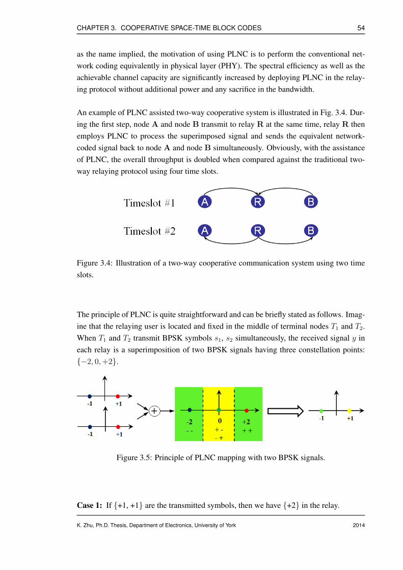
CHAPTER 3. COOPERATIVE SPACE-TIME BLOCK CODES 54
as the name implied, the motivation of using PLNC is to perform the conventional net-work coding equivalently in physical layer (PHY). The spectral efficiency as well as theachievable channel capacity are significantly increased by deploying PLNC in the relay-ing protocol without additional power and any sacrifice in the bandwidth.
An example of PLNC assisted two-way cooperative system is illustrated in Fig. 3.4. Dur-ing the first step, node A and node B transmit to relay R at the same time, relay R thenemploys PLNC to process the superimposed signal and sends the equivalent network-coded signal back to node A and node B simultaneously. Obviously, with the assistanceof PLNC, the overall throughput is doubled when compared against the traditional two-way relaying protocol using four time slots.
Figure 3.4: Illustration of a two-way cooperative communication system using two timeslots.
The principle of PLNC is quite straightforward and can be briefly stated as follows. Imag-ine that the relaying user is located and fixed in the middle of terminal nodes T1 and T2.When T1 and T2 transmit BPSK symbols s1, s2 simultaneously, the received signal y ineach relay is a superimposition of two BPSK signals having three constellation points:−2, 0,+2.
Figure 3.5: Principle of PLNC mapping with two BPSK signals.
Case 1: If +1, +1 are the transmitted symbols, then we have +2 in the relay.
K. Zhu, Ph.D. Thesis, Department of Electronics, University of York 2014
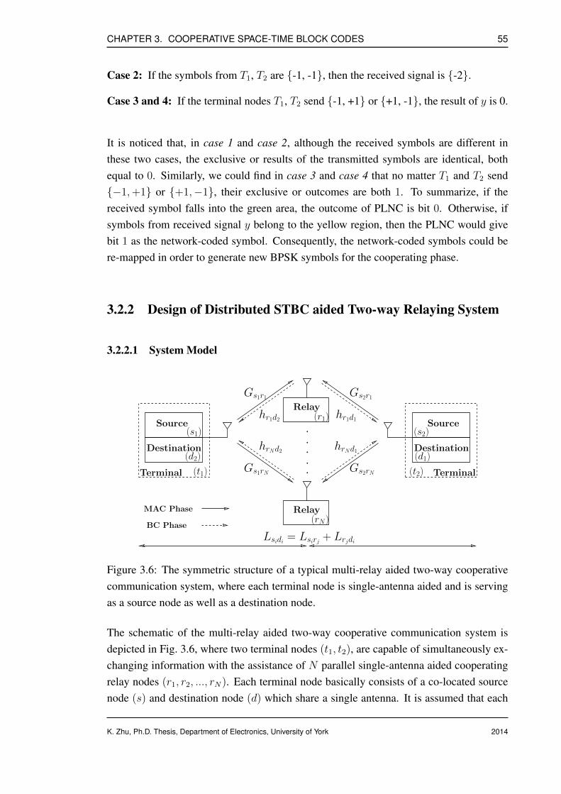
CHAPTER 3. COOPERATIVE SPACE-TIME BLOCK CODES 55
Case 2: If the symbols from T1, T2 are -1, -1, then the received signal is -2.
Case 3 and 4: If the terminal nodes T1, T2 send -1, +1 or +1, -1, the result of y is 0.
It is noticed that, in case 1 and case 2, although the received symbols are different inthese two cases, the exclusive or results of the transmitted symbols are identical, bothequal to 0. Similarly, we could find in case 3 and case 4 that no matter T1 and T2 send−1,+1 or +1,−1, their exclusive or outcomes are both 1. To summarize, if thereceived symbol falls into the green area, the outcome of PLNC is bit 0. Otherwise, ifsymbols from received signal y belong to the yellow region, then the PLNC would givebit 1 as the network-coded symbol. Consequently, the network-coded symbols could bere-mapped in order to generate new BPSK symbols for the cooperating phase.
3.2.2 Design of Distributed STBC aided Two-way Relaying System
3.2.2.1 System Model
MAC Phase
BC Phase
Destination
Terminal
Source
Relay
··
···
Gs1r1
Gs1rN
Gs2r1
hrNd1hrNd2 Destination
Terminal
Source(s1)
(d2)Gs2rN (t2)
(s2)
(d1)
(t1)
Lsidi = Lsirj + Lrjdi
hr1d1
Relay(r1)hr1d2
(rN)
Figure 3.6: The symmetric structure of a typical multi-relay aided two-way cooperativecommunication system, where each terminal node is single-antenna aided and is servingas a source node as well as a destination node.
The schematic of the multi-relay aided two-way cooperative communication system isdepicted in Fig. 3.6, where two terminal nodes (t1, t2), are capable of simultaneously ex-changing information with the assistance of N parallel single-antenna aided cooperatingrelay nodes (r1, r2, ..., rN). Each terminal node basically consists of a co-located sourcenode (s) and destination node (d) which share a single antenna. It is assumed that each
K. Zhu, Ph.D. Thesis, Department of Electronics, University of York 2014
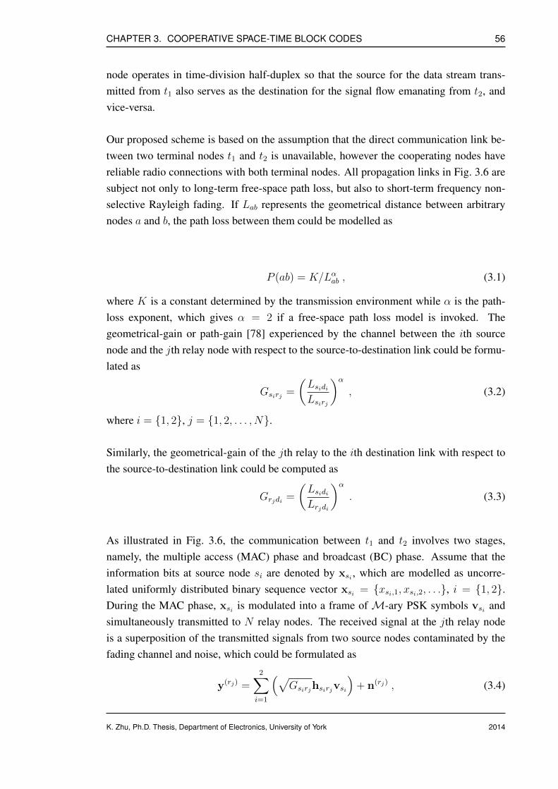
CHAPTER 3. COOPERATIVE SPACE-TIME BLOCK CODES 56
node operates in time-division half-duplex so that the source for the data stream trans-mitted from t1 also serves as the destination for the signal flow emanating from t2, andvice-versa.
Our proposed scheme is based on the assumption that the direct communication link be-tween two terminal nodes t1 and t2 is unavailable, however the cooperating nodes havereliable radio connections with both terminal nodes. All propagation links in Fig. 3.6 aresubject not only to long-term free-space path loss, but also to short-term frequency non-selective Rayleigh fading. If Lab represents the geometrical distance between arbitrarynodes a and b, the path loss between them could be modelled as
P (ab) = K/Lαab , (3.1)
where K is a constant determined by the transmission environment while α is the path-loss exponent, which gives α = 2 if a free-space path loss model is invoked. Thegeometrical-gain or path-gain [78] experienced by the channel between the ith sourcenode and the jth relay node with respect to the source-to-destination link could be formu-lated as
Gsirj =
(LsidiLsirj
)α, (3.2)
where i = 1, 2, j = 1, 2, . . . , N.
Similarly, the geometrical-gain of the jth relay to the ith destination link with respect tothe source-to-destination link could be computed as
Grjdi =
(LsidiLrjdi
)α. (3.3)
As illustrated in Fig. 3.6, the communication between t1 and t2 involves two stages,namely, the multiple access (MAC) phase and broadcast (BC) phase. Assume that theinformation bits at source node si are denoted by xsi , which are modelled as uncorre-lated uniformly distributed binary sequence vector xsi = xsi,1, xsi,2, . . ., i = 1, 2.During the MAC phase, xsi is modulated into a frame of M-ary PSK symbols vsi andsimultaneously transmitted to N relay nodes. The received signal at the jth relay nodeis a superposition of the transmitted signals from two source nodes contaminated by thefading channel and noise, which could be formulated as
y(rj) =2∑
i=1
(√Gsirjhsirjvsi
)+ n(rj) , (3.4)
K. Zhu, Ph.D. Thesis, Department of Electronics, University of York 2014

CHAPTER 3. COOPERATIVE SPACE-TIME BLOCK CODES 57
where j ∈ 1, 2, . . . , N. Furthermore, the complex-valued vector hsirj denotes thequasi-static frequency-flat Rayleigh fading coefficients of the communication link be-tween the ith source node and the jth relay node which remain constant over two sym-bol intervals, while the complex-valued vector n(rj) is the additive white Gaussian noise(AWGN) introduced in the jth relay node with zero mean and variance of N0/2 per di-mension.
It is assumed that the DF relaying strategy is incorporated in our system. Therefore,during the BC stage, a CRC-based selective relaying algorithm is employed in each relaynode to eliminate error propagation. More specifically, only correctly estimated bits arere-encoded and transmitted to the destination nodes. A frame of virtual STBC codewordsw(rj) are constructed by N cooperating relay nodes in a distributed fashion, yielding
w(rj) = [w(r1), w(r2), . . . , w(rN )]T , (3.5)
where the notation w(rj) represents the distributed STBC symbols contributed from thejth relay node after the PLNC mapping. The received signal at the ith destination node isgiven by
y(di) =N∑
j=1
(√Grjdihrjdiw
(rj))
+ n(di) , (3.6)
where i ∈ 1, 2. A similar vector hrjdi denotes the complex-valued Rayleigh blockfading coefficients of the channel between the jth relay node and the ith destination node,while the complex-valued vector n(di) is the AWGN induced in the ith destination nodehaving zero mean and variance of N0/2 per dimension.
At the destination node, a serially-concatenated conventional STBC decoder, PSK demap-per and PLNC demapper are invoked to perform the final decision and recover the infor-mation transmitted from the source nodes. Note that we assume the transmit power ofeach node is normalized to unity. Hence, each relay node transmits at 1/N of the overallpower to ensure that
∑Nj=1 |w(rj)|2 = 1 for the purpose of offering a fair comparison.
3.2.2.2 Principle of CRC-based Selective Relaying
Fig. 3.7 illustrates the architecture of source and relay nodes for the proposed CRC-basedrelay selection aided distributed STBC scheme. For ease of analysis, in this subsection,we consider a two-way cooperative STBC system with N = 2 relay nodes, which is ca-pable of achieving full diversity order with a relatively low complexity. Also, we assume
K. Zhu, Ph.D. Thesis, Department of Electronics, University of York 2014

CHAPTER 3. COOPERATIVE SPACE-TIME BLOCK CODES 58
PSK
Mapper
PSK
Mapper
PLNC
Mapper
PLNC
Mapper
PSK
Mapper
PSK
Mapper
DSTBC
Encoder
DSTBC
Encoder
xs1
y(r2)u(r2)e(r2)w(r2)
Source node 1&2
CRC
CRC
y(r1)u(r1)e(r1)w(r1)
Relay node 1&2
vs1
vs1
Channel hs1r1
Channel hs1r2
vs2
vs2
Channel hs2r1
Channel hs2r2
xs2
Figure 3.7: The schematic of the source and relay nodes for the proposed novel PLNCaided distributed STBC scheme with selection relaying strategy, where two distributedsource and relay nodes are drawn in parallel for simplicity.
K. Zhu, Ph.D. Thesis, Department of Electronics, University of York 2014
CHAPTER 3. COOPERATIVE SPACE-TIME BLOCK CODES 59
binary phase shift keying (BPSK) is employed as the modulation scheme in all source andrelay nodes. The cooperating users are located mid way between t1 and t2, so that
Lsirj = Lrjdi =Lsidi
2. (3.7)
Hence, according to Eq. (3.2) and Eq. (3.3), we have
Gsirj = Grjdi = 22 = 4 . (3.8)
As discussed earlier, the signal received by each relay node is the superposition of twonoise-corrupted BPSK-modulated signals simultaneously transmitted from s1 and s2,which could be formulated as Eq. (3.4). In order to make sure the destination nodescan successfully extract the useful information, the received superimposed signal has tobe transformed to network-coded symbols which are then transmitted by the relay duringthe broadcast phase. The most straightforward method is that each relay node detects andrecovers the explicit information bits x(rj)
s1 and x(rj)s2 from the superimposed signal individ-
ually and then performs bit-wise exclusive or (XOR) arithmetic over the estimated databits to acquire the network-coded symbol sequence. At the jth relay node, if x(rj)
si is theestimate of information bits transmitted from the ith source node, the result of networkcoding could be expressed as
u(rj) = x(rj)s1⊕ x(rj)
s2, (3.9)
where ⊕ represents the addition operation in the Galois field GF(2m), which can be sim-plified to the exclusive or (XOR) arithmetic when m = 1.
It is clear that the responsibility of a relay node is to facilitate the final decision at thedestination and make sure that the information of interest could be extracted correctly,and hence to fully detect the received signal at the relay node is unnecessary and couldmake proposed scheme inferior in terms of spectral efficiency. The unique nature ofPLNC makes it possible to transform the estimate of two superimposed BPSK-modulatedsignals directly to the equivalent network-coded symbols shown in Eq. (3.9) instead ofdetecting the information separately. In other words, the PLNC mapping is fulfilled withintwo time slots, the reduction of intermediate processing steps could potentially lead tosignificant spectral efficiency gain and energy saving. For a BPSK-modulated symbol,there are two possible phasor combinations, namely, vsi ∈ −1,+1, where i = 1, 2.Therefore, the constellation of the summation of two BPSK symbols could be describedas z = (vs1 + vs2) ∈ χ, where χ = −2, 0,+2. If the superposition of two BPSKsymbols is denoted by z(rj) at the jth relay node, then the estimate of z(rj) is computed as
z(rj) = arg minz∈χ
∥∥∥y(rj) −2∑
i=1
(√Gsirjhsirjvsi
)∥∥∥2
, (3.10)
K. Zhu, Ph.D. Thesis, Department of Electronics, University of York 2014

CHAPTER 3. COOPERATIVE SPACE-TIME BLOCK CODES 60
where j ∈ 1, 2 and ||(·)|| is the Frobenius norm of variable (·).
After the summation of two BPSK-modulated signals is estimated, PLNC is applied toobtain the network-coded bits u(rj) as follows
u(rj) = mod
(z(rj)
2− 1, 2
)= x(rj)
s1⊕ x(rj)
s2, (3.11)
where mod (a, b) represents the modulus after division between a and b. For example, ifwe assume z(rj) = −2, 0,+2, the network-coded bits u(rj) could be calculated basedon Eq. (3.11), which gives u(rj) = 0, 1, 0.
In view of the potential error propagation introduced in the decoding and re-encodingprocess, an error-detecting code based selective relaying or opportunistic relaying strat-egy is deployed in each relay node. Since CRC has been widely implemented in manycommercial mobile networks, it would not significantly decrease the data rate or exertadditional complexity on the system design. The construction of a robust error-detectingcode, such as CRC code, primarily lies in the selection of an appropriate generator poly-nomial which should be designed to maximize the error detecting capabilities. We usethe CRC-8 algorithm, a well-known and commonly used polynomial with excellent errordetecting capability which has been adopted in the WCDMA cellular network [79]. Thegenerator polynomial of CRC-8 algorithm is given by Γ = [x8 + x7 + x4 + x3 + x + 1],which corresponds to the 9-bit string 110011011.
In the source nodes, the 9-bit CRC algorithm is carried out automatically to computethe CRCs of each frame of information bits before transmission. The PLNC-coded datastream could be treated as the XOR combination (modulo-2 sum) of two estimated infor-mation sequences transmitted from both source nodes.
The linearity of the CRC [80] implies that if two sequences pass the same CRC, theirmodulo-2 sum will also pass. Moreover if one is in error, or both are in error but in differ-ent positions, the validation will fail. Hence if the CRCs computed from the PLNC-codedsignal perfectly match that acquired by performing the XOR operation on the CRCs pro-vided by the source nodes, the relay nodes will map u(rj) to BPSK-modulated symbolse(rj) and feed e(rj) to the distributed STBC encoder. On the other hand, if those twovalues are not identical, the relay node is instructed to maintain silence during that trans-mission period. The re-modulated BPSK symbols in e(rj) are then grouped into pairs inorder to construct distributed STBC codewords in the next step. One of the most distinctcharacteristics differentiating the distributed STBC from conventional STBC using co-located antennas is that each column of the distributed STBC codewords is constituted bya different relaying user and is transmitted through an independent antenna.
K. Zhu, Ph.D. Thesis, Department of Electronics, University of York 2014

CHAPTER 3. COOPERATIVE SPACE-TIME BLOCK CODES 61
As portrayed in Fig. 3.7, two cooperating relay nodes act like a twin-antenna aided MIMOtransmitter, although both of them are equipped with a single antenna. The design of thedistributed STBC encoder is based on the Alamouti scheme with two transmit antennasand one receive antenna, which could be described as follows at time index T
G2 =
g1 −g∗2g2 g∗1
=
e(r1)|T −e(r2)∗|T
e(r1)|T+1 e(r2)∗|T+1
. (3.12)
In the destination node shown in Fig. 3.8, a conventional Alamouti STBC decoder as wellas a BPSK demapper are employed to recover the PLNC-coded symbols u(rj). Then eachdestination node could extract the useful information transmitted by the correspondingsource node with the assistance of their local information as follows
xs1 = u(rj) ⊕ xs2 . (3.13)
Similarly, we have
xs2 = u(rj) ⊕ xs1 , (3.14)
where j = 1 or 2.
In the event that both relay nodes fail to transmit in the BC phase, the destination nodeswill make arbitrary assumptions about that pair of transmitted bits. In our simulations0, 0 is assumed. Note that the choice will not influence the end-to-end BER perfor-mance significantly since we assume the information sources in t1 and t2 are equiproba-ble.
Alamouti
STBC
Decoder
PSK
Demapper
PLNC
Demapper
y(di) e(rj) u(rj) xsi
Destination node i
Figure 3.8: The schematic of the ith destination node for the proposed novel PLNC aideddistributed STBC scheme with selection relaying strategy when both relay nodes cancorrectly decode the signals transmitted from two source nodes, where i, j ∈ 1, 2.
K. Zhu, Ph.D. Thesis, Department of Electronics, University of York 2014
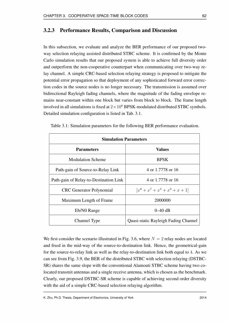
CHAPTER 3. COOPERATIVE SPACE-TIME BLOCK CODES 62
3.2.3 Performance Results, Comparison and Discussion
In this subsection, we evaluate and analyze the BER performance of our proposed two-way selection relaying assisted distributed STBC scheme. It is confirmed by the MonteCarlo simulation results that our proposed system is able to achieve full diversity orderand outperform the non-cooperative counterpart when communicating over two-way re-lay channel. A simple CRC-based selection relaying strategy is proposed to mitigate thepotential error propagation so that deployment of any sophisticated forward error correc-tion codes in the source nodes is no longer necessary. The transmission is assumed overbidirectional Rayleigh fading channels, where the magnitude of the fading envelope re-mains near-constant within one block but varies from block to block. The frame lengthinvolved in all simulations is fixed at 2×10⁶ BPSK-modulated distributed STBC symbols.Detailed simulation configuration is listed in Tab. 3.1.
Table 3.1: Simulation parameters for the following BER performance evaluation.
Simulation Parameters
Parameters Values
Modulation Scheme BPSK
Path-gain of Source-to-Relay Link 4 or 1.7778 or 16
Path-gain of Relay-to-Destination Link 4 or 1.7778 or 16
CRC Generator Polynomial [x8 + x7 + x4 + x3 + x+ 1]
Maximum Length of Frame 2000000
Eb/N0 Range 0–40 dB
Channel Type Quasi-static Rayleigh Fading Channel
We first consider the scenario illustrated in Fig. 3.6, where N = 2 relay nodes are locatedand fixed in the mid-way of the source-to-destination link. Hence, the geometrical-gainfor the source-to-relay link as well as the relay-to-destination link both equal to 4. As wecan see from Fig. 3.9, the BER of the distributed STBC with selection relaying (DSTBC-SR) shares the same slope with the conventional Alamouti STBC scheme having two co-located transmit antennas and a single receive antenna, which is chosen as the benchmark.Clearly, our proposed DSTBC-SR scheme is capable of achieving second order diversitywith the aid of a simple CRC-based selection relaying algorithm.
K. Zhu, Ph.D. Thesis, Department of Electronics, University of York 2014

CHAPTER 3. COOPERATIVE SPACE-TIME BLOCK CODES 63
10-5
10-4
10-3
10-2
10-1
1
0 5 10 15 20 25 30 35 4010
-5
10-4
10-3
10-2
10-1
1
BER
0 5 10 15 20 25 30 35 40
Eb/N0 (dB)
Tx = 1, Rx = 1 (SISO)
Tx = 2, Rx = 1 (Alamouti STBC)
DSTBC-SR (relays in the mid-point)
DSTBC-NO-SR (relays in the mid-point)
DSTBC-SR (relays not in the mid-point)
Figure 3.9: BER versus Eb/N0 performance of the proposed novel PLNC aided dis-tributed STBC scheme with selection relaying strategy when communicating overRayleigh block fading channel, where the frame length is 2× 10⁶.
K. Zhu, Ph.D. Thesis, Department of Electronics, University of York 2014

CHAPTER 3. COOPERATIVE SPACE-TIME BLOCK CODES 64
Furthermore, the DSTBC-SR scheme outperforms the non-cooperative benchmark by ap-proximately 4.0 dB at BER = 10−4. This performance gain demonstrates that the CRC-based selection relaying protocol is a low-complexity but efficient solution to preservingthe orthogonality of the distributed space-time coded signals when transmitted by a groupof cooperating relay nodes.
Fig. 3.9 also shows that, even though the cooperation stage is assisted by multiple relaynodes, the performance of distributed STBC scheme without an appropriately designedselection relaying strategy (DSTBC-NO-SR) is similar to that of a single antenna systemproviding only first order diversity. This detrimental effect generally results from errorpropagation in the relay nodes, which degrades the BER performance by more than 11.0
dB in comparison to its counterpart employing a selection relaying protocol at BER =10−3.
0
10%
20%
30%
40%
50%
60%
70%
80%
90%
100%
0 2 4 6 8 100
10%
20%
30%
40%
50%
60%
70%
80%
90%
100%
Percentage
0 2 4 6 8 10
Eb/N0 (dB)
R1, R2 Correct
R1 Correct, R2 Erroneous
R1 Erroneous, R2 Correct
R1, R2 Erroneous
Figure 3.10: Bar chart for the percentage of correctly and erroneously decoded bits in tworelay nodes at different Eb/N0, where the total number of bits is fixed to 2× 10⁶.
Fig. 3.10 demonstrates the percentage of correctly and erroneously decoded bits in tworelay nodes when the Eb/N0 is increasing from 0.0 dB to 10.0 dB. For N = 2 relaynodes, four different relaying scenarios could be generalized as follows:
K. Zhu, Ph.D. Thesis, Department of Electronics, University of York 2014
CHAPTER 3. COOPERATIVE SPACE-TIME BLOCK CODES 65
1) Relay 1 (R1) and Relay 2 (R2) both decode correctly;2) R1 decodes correctly while R2 decodes erroneously;3) R1 decodes erroneously while R2 decodes correctly;4) Neither R1 nor R2 decode correctly.
As shown in Fig. 3.10, more than 68% of the total bits transmitted from the source nodescan be decoded correctly using PLNC in both relay nodes even when the Eb/N0 = 0.0
dB, while the percentage soars to almost 100% when the Eb/N0 grows to 10.0 dB. Onthe other hand, the percentage of erroneously decoded bits in both relay nodes is lessthan 5% in the worst case when the Eb/N0 = 0.0 dB. In other words, more than 68% ofthe PLNC-coded bits transmitted from two relay nodes could be used to construct validdistributed Alamouti space-time codewords. There is a higher probability (more than95%) that at least one of the two relay nodes will be active and help other users to forwardtheir information.
We also investigate an asymmetric system architecture, where relay node r1 moves to-wards destination node d1, while the other relay r2 moves towards d2. We assumethe distance between each relay node and the nearest destination node is one quar-ter of that between two terminal nodes t1 and t2. In other words, we could defineLr1d1 = Lr2d2 = Lt1t2/4. Then, the geometrical-gain experienced by each mobile channelcould be computed based on Eqs. (3.2), (3.3), yielding:
Gs1r1 = Gs2r2 = Gr1d2 = Gr2d1 = (1/0.75)2 = 1.7778 . (3.15)
Similarly, we have:
Gs2r1 = Gs1r2 = Gr1d1 = Gr2d2 = (1/0.25)2 = 16 . (3.16)
It is shown in Fig. 3.9 that the DSTBC-SR scheme with new relay locations is also capableof achieving second order transmit diversity, although the performance is approximately1.0 dB worse than in the previous scenario. During the MAC as well as the BC stages,although half of the communication links are improved, having a geometrical-gain of 16;the remaining half, having a gain of 1.7778, are unable to provide reliable transmission.This leads to the decoding performance in one relay node being better than that in theother. As discussed above, a valid space-time codeword could be constructed only whenboth of the relay nodes achieve error-free decoding. Hence, the BER performance of thenew case slightly degrades by about 1.0 dB compared with the DSTBC-SR with centrallylocated relay nodes.
K. Zhu, Ph.D. Thesis, Department of Electronics, University of York 2014
CHAPTER 3. COOPERATIVE SPACE-TIME BLOCK CODES 66
3.3 Numerical Analysis of Distributed STBC aided Two-way Relaying System
After the discussion of system model and principle of relay selection assisted distributedSTBC over the bidirectional relay channel in subsection 3.2.2.1 and subsection 3.2.2.2, inthis subsection our focus is shifted to the analytical evaluation of the proposed scheme.Compared with the traditional probability distribution function (PDF) based approach, itis more convenient to analyze and solve the theoretical error performance by utilizing themoment generating function (MGF) method. It provides a unified way to measure the biterror probability (BEP) or pairwise error probability (PEP) of a specific system commu-nicating over diverse fading channels such as Rayleigh fading, Nakagami-n (Rician) andNakagami-m. This subsection commences from the introduction of mathematical prelim-inaries, and then concentrates on the error probability analysis of the average end-to-endBEP performance based on a bound approach, where tight upper and lower bounds arederived. After that, the analysis is extended to obtain the exact expression of the averageend-to-end BEP.
3.3.1 Mathematical Preliminaries
In general, average signal-to-noise ratio and average bit error probability are widely usedto reflect the performance of a specific system. The average SNR measured at the outputof the receiver is able to give an immediate reflection of the quality of a communicationsystem. If it is assumed that the instantaneous SNR is denoted by γ, according to [16],the average SNR can be defined as
γ ,∫ ∞
0
γpγ(γ) dγ , (3.17)
where pγ(γ) represents the probability distribution function of γ.
Note that the term ‘average’ means statistically average γ over the probability distributionof the fading.
The other criterion is the average BEP, which is the most commonly used in the literatureto reveal the nature of a radio communication system. Average BEP can be computed byusing the following formula given in [16]
Pb(E) ,∫ ∞
0
Pb(E|γ)pγ(γ) dγ , (3.18)
K. Zhu, Ph.D. Thesis, Department of Electronics, University of York 2014

CHAPTER 3. COOPERATIVE SPACE-TIME BLOCK CODES 67
where Pb(E|γ) is the conditional BEP of the received signal, which, take PSK modulationfor example, is written as Q-function. Therefore, the evaluation of average BEP overfading channel now becomes averaging the Q-function over the probability distributionof fading.
The Gaussian Q-function is defined in the form of a semi-infinite integral as shown in [16]
Q(x) ,∫ ∞
x
1√2π
exp
(−y
2
2
)dy . (3.19)
The difficulty of evaluating the average BEP primarily lies in the fact that the conditionalBEP is generally a non-linear function of the instantaneous SNR γ. Furthermore, fromthe expression of the Q-function, we note that the argument of the function is in the lowerlimit of the integral, which poses analytical difficulties when averaging statistically overits probability distribution. As a solution, Craig’s Q-function [16] offers an alternative.
Q(x) =1
π
∫ π2
0
exp
(− x2
2 sin2 θ
)dθ . (3.20)
Now the expression of this Q-function is more desirable because the argument of thisfunction is in neither the upper nor lower limits of the integral and the integrand is anelementary function. More importantly, the upper and lower limits are finite. As a result,the calculation of average BEP can be significantly simplified as
Pb(E) =
∫ ∞
0
Q(a√γ)pγ(γ) dγ
=
∫ ∞
0
1
π
∫ π2
0
exp
(− a2γ
2 sin2 θ
)dθ pγ(γ) dγ
=1
π
∫ π2
0
[∫ ∞
0
exp
(− a2γ
2 sin2 θ
)pγ(γ) dγ
]dθ
=1
π
∫ π2
0
Mγ
(− a2
2 sin2 θ
)dθ , (3.21)
where Mγ(s) =∫∞
0esγpγ(γ) dγ denotes the moment generating function of the instanta-
neous SNR, which only depends on the fading channel model , whereas the scalar a is aconstant depending on the modulation scheme.
If compare the MGF of the instantaneous SNR γ with the definition of Laplace transform
L f(t) =
∫ ∞
0
e−stf(t) dt , (3.22)
we can interestingly find that the MGF of the instantaneous SNR γ is the Laplace trans-form of Pb(E|γ), but reversing the sign of exponent, namely
L pγ(γ) = Mγ(−s) . (3.23)
K. Zhu, Ph.D. Thesis, Department of Electronics, University of York 2014
CHAPTER 3. COOPERATIVE SPACE-TIME BLOCK CODES 68
3.3.2 Upper and Lower Bound of Average End-to-End BEP for Pro-posed Distributed STBC System
The average end-to-end error probability measured at the output of the receiver, is definedas the average of the instantaneous end-to-end BEP over all possible random channel co-efficients. Mathematically, if PEtoE denotes the instantaneous end-to-end BEP, the desiredaverage end-to-end error probability PEtoE is computed as the statistical expectation ofthe instantaneous end-to-end BEP, namely,
PEtoE = E [PEtoE] . (3.24)
In addition, recall the structure of cooperative STBC scheme depicted in subsec-tion 3.2.2.1. The instantaneous end-to-end BEP PEtoE represents the average of the in-stantaneous error probabilities at terminal node t1 and t2 denoted as P ti
EtoE , this yields
PEtoE = E[P tiEtoE
], i = 1, 2
=1
2
2∑
i=1
P tiEtoE . (3.25)
Furthermore, as mentioned in subsection 3.2.2.2, the transmissions of the re-encodedsignals in the BC phase involve four different opportunistic relaying scenarios, corre-sponding to the results of the CRC verification. Hence the instantaneous end-to-end errorprobability at terminal node ti (i = 1, 2) can be formulated as follows
P tiEtoE = P ti
DSTBC(1− PMAC,r1)(1− PMAC,r2)︸ ︷︷ ︸r1, r2 both decode correctly
+ P r1→tiBPSK(1− PMAC,r1)PMAC,r2︸ ︷︷ ︸
r1 decodes correctly, r2 decodes erroneously
+ P r2→tiBPSKPMAC,r1(1− PMAC,r2)︸ ︷︷ ︸
r1 decodes erroneously, r2 decodes correctly
+1
2PMAC,r1PMAC,r2︸ ︷︷ ︸
r1, r2 both decode erroneously
, (3.26)
where the notations used in Eq. (3.26) are summarized as follows:
• PMAC,r1 and PMAC,r2 are the instantaneous error probabilities of the received sig-nals at relay node r1 and r2 during the MAC phase, respectively.
• P tiDSTBC represents the instantaneous BEP of the distributed Alamouti STBC re-
ceived at terminal node ti (i = 1, 2) during the BC phase, which corresponds to thecase when both relay nodes r1 and r2 successfully decode the signal. In this case,both relay nodes are capable of transmitting and forwarding the re-encoded signalsto destination nodes. Hence, the virtual distributed Alamouti STBC frame is jointlyconstructed.
K. Zhu, Ph.D. Thesis, Department of Electronics, University of York 2014
CHAPTER 3. COOPERATIVE SPACE-TIME BLOCK CODES 69
• P r1→tiBPSK and P r2→ti
BPSK denote the instantaneous BEP of the BPSK signals received atterminal node ti (i = 1, 2) during the BC phase. This corresponds to the case wheneither relay node r1 or r2 successfully decode the signal; therefore, only one relaynode is able to forward the re-encoded signal to destination nodes and the receivedsignal at the destination seems like a BPSK-modulated signal while the other relaynode stays silent.
• For the case when none of the two relay nodes achieves error-free decoding, thetransmission from the relay is halted during the BC stage and the destination nodesassume (as discussed above) that the pair of information bits contained in the miss-ing packet is 0, 0. Therefore, the probability of making an erroneous judgmentfor each bit is 0.5.
If z represents the exclusive or combination of the information bits from two source nodes,where z = xs1 ⊕ xs2 , the definition of the instantaneous BEP of the MAC phase at relaynode r1 can be described as the probability that symbols from u(r1) are not identical tothose transmitted in z for given complex-valued fading channel coefficients hs1r1 andhs2r1 . Thus we have
PMAC,r1 , Pr[z 6= u(r1)|hs1r1 , hs2r1
], (3.27)
where hsirj is the complex-valued fading coefficients of the channel between si and rj ,i = j = 1, 2.
Similarly, the instantaneous BEP of the MAC phase at relay node r2 is given by
PMAC,r2 , Pr[z 6= u(r2)|hs1r2 , hs2r2
]. (3.28)
According to the analysis in [81], we know that PMAC,ri is upper bounded by P (U)MAC,ri
which is given by the sum of the instantaneous BEP of the propagation paths from twosource nodes to relay nodes; while it is lower bounded by P (L)
MAC,riwhich is determined
by the instantaneous BEP of the weaker link (i = 1, 2). Since simple BPSK modulationis used in source and relay nodes, the tight upper bound and tight lower bound can beexpressed as
Tight Upper Bound:
PMAC,r1 < P(U)MAC,r1
= Q(√
2γs1r1
)+Q
(√2γs2r1
), (3.29)
PMAC,r2 < P(U)MAC,r2
= Q(√
2γs1r2
)+Q
(√2γs2r2
), (3.30)
K. Zhu, Ph.D. Thesis, Department of Electronics, University of York 2014
CHAPTER 3. COOPERATIVE SPACE-TIME BLOCK CODES 70
Tight Lower Bound:
PMAC,r1 > P(L)MAC,r1
= Q(√
2 min[γs1r1 , γs2r1 ]), (3.31)
PMAC,r2 > P(L)MAC,r2
= Q(√
2 min[γs1r2 , γs2r2 ]), (3.32)
where γsirj = Gsirj |hsirj |2Esi/σ2 is the linear signal-to-noise ratio (SNR) measured atthe transmitter when source node si is communicating with relay node rj . Furthermore,Esi denotes the transmit power which is normalized to unity, while σ2 is the variance ofthe AWGN, i = j = 1, 2.
Therefore, Eq. (3.26) can now be re-written and the average end-to-end error probabilityof the novel bidirectional relaying aided distributed STBC system is upper bounded andlower bounded by
P(U)EtoE = E
1
2
[ Part I︷ ︸︸ ︷(1− P (L)
MAC,r1
)(1− P (L)
MAC,r2
) (P t1DSTBC + P t2
DSTBC
)
+(
1− P (L)MAC,r1
)P
(U)MAC,r2
(P r1→t1BPSK + P r1→t2
BPSK
)︸ ︷︷ ︸
Part II
+ P(U)MAC,r1
(1− P (L)
MAC,r2
) (P r2→t1BPSK + P r2→t2
BPSK
)︸ ︷︷ ︸
Part III
+P(U)MAC,r1
P(U)MAC,r2︸ ︷︷ ︸
Part IV
],
(3.33)
P(L)EtoE = E
1
2
[ Part I︷ ︸︸ ︷(1− P (U)
MAC,r1
)(1− P (U)
MAC,r2
) (P t1DSTBC + P t2
DSTBC
)
+(
1− P (U)MAC,r1
)P
(L)MAC,r2
(P r1→t1BPSK + P r1→t2
BPSK
)︸ ︷︷ ︸
Part II
+ P(L)MAC,r1
(1− P (U)
MAC,r2
) (P r2→t1BPSK + P r2→t2
BPSK
)︸ ︷︷ ︸
Part III
+P(L)MAC,r1
P(L)MAC,r2︸ ︷︷ ︸
Part IV
].
(3.34)
Next, we expand Eq. (3.33) and Eq. (3.34), then solve the expectations term by term dueto the linearity of the integrals. The final expression of the average end-to-end BEP can
K. Zhu, Ph.D. Thesis, Department of Electronics, University of York 2014
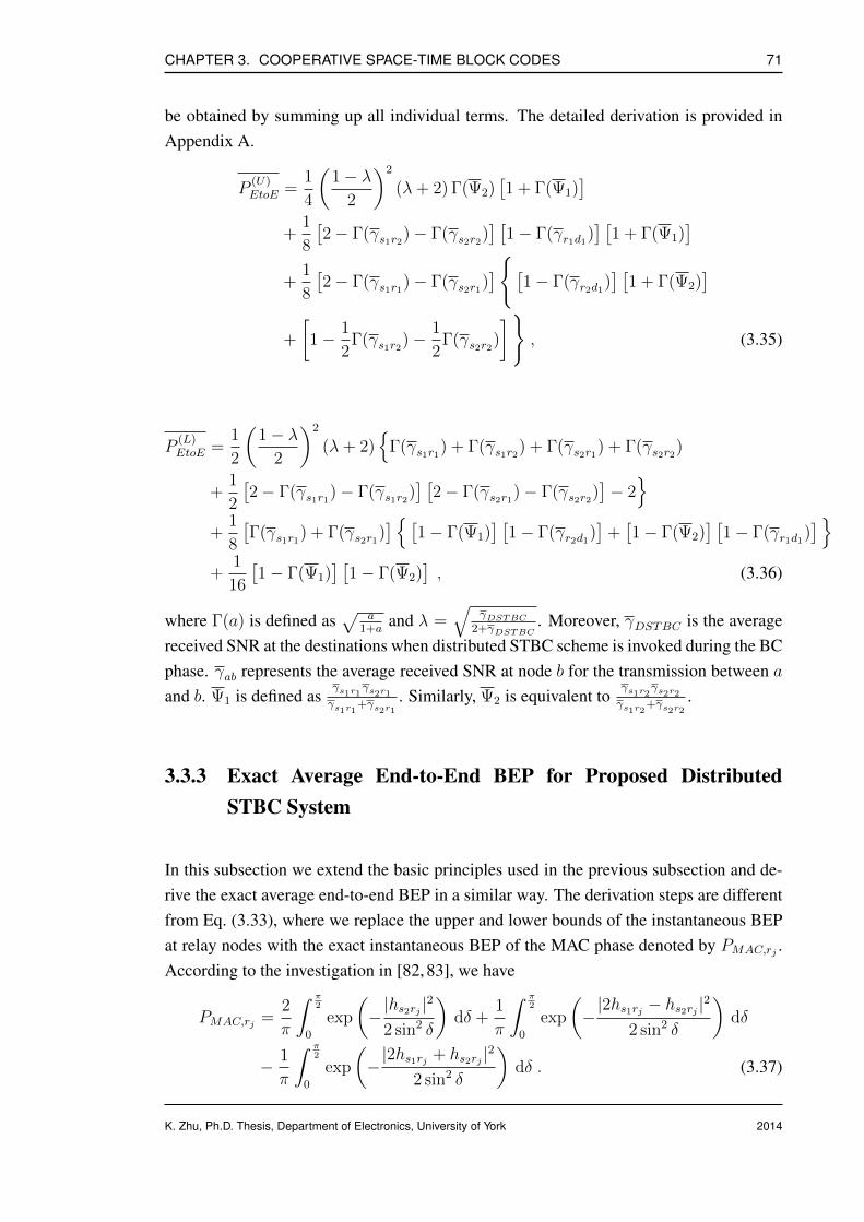
CHAPTER 3. COOPERATIVE SPACE-TIME BLOCK CODES 71
be obtained by summing up all individual terms. The detailed derivation is provided inAppendix A.
P(U)EtoE =
1
4
(1− λ
2
)2
(λ+ 2) Γ(Ψ2)[1 + Γ(Ψ1)
]
+1
8
[2− Γ(γs1r2)− Γ(γs2r2)
] [1− Γ(γr1d1)
] [1 + Γ(Ψ1)
]
+1
8
[2− Γ(γs1r1)− Γ(γs2r1)
][1− Γ(γr2d1)
] [1 + Γ(Ψ2)
]
+
[1− 1
2Γ(γs1r2)−
1
2Γ(γs2r2)
], (3.35)
P(L)EtoE =
1
2
(1− λ
2
)2
(λ+ 2)
Γ(γs1r1) + Γ(γs1r2) + Γ(γs2r1) + Γ(γs2r2)
+1
2
[2− Γ(γs1r1)− Γ(γs1r2)
] [2− Γ(γs2r1)− Γ(γs2r2)
]− 2
+1
8
[Γ(γs1r1) + Γ(γs2r1)
] [1− Γ(Ψ1)
] [1− Γ(γr2d1)
]+[1− Γ(Ψ2)
] [1− Γ(γr1d1)
]
+1
16
[1− Γ(Ψ1)
] [1− Γ(Ψ2)
], (3.36)
where Γ(a) is defined as√
a1+a
and λ =√
γDSTBC2+γDSTBC
. Moreover, γDSTBC is the averagereceived SNR at the destinations when distributed STBC scheme is invoked during the BCphase. γab represents the average received SNR at node b for the transmission between aand b. Ψ1 is defined as
γs1r1γs2r1γs1r1+γs2r1
. Similarly, Ψ2 is equivalent toγs1r2γs2r2γs1r2+γs2r2
.
3.3.3 Exact Average End-to-End BEP for Proposed DistributedSTBC System
In this subsection we extend the basic principles used in the previous subsection and de-rive the exact average end-to-end BEP in a similar way. The derivation steps are differentfrom Eq. (3.33), where we replace the upper and lower bounds of the instantaneous BEPat relay nodes with the exact instantaneous BEP of the MAC phase denoted by PMAC,rj .According to the investigation in [82, 83], we have
PMAC,rj =2
π
∫ π2
0
exp
(−|hs2rj |
2
2 sin2 δ
)dδ +
1
π
∫ π2
0
exp
(−|2hs1rj − hs2rj |
2
2 sin2 δ
)dδ
− 1
π
∫ π2
0
exp
(−|2hs1rj + hs2rj |2
2 sin2 δ
)dδ . (3.37)
K. Zhu, Ph.D. Thesis, Department of Electronics, University of York 2014
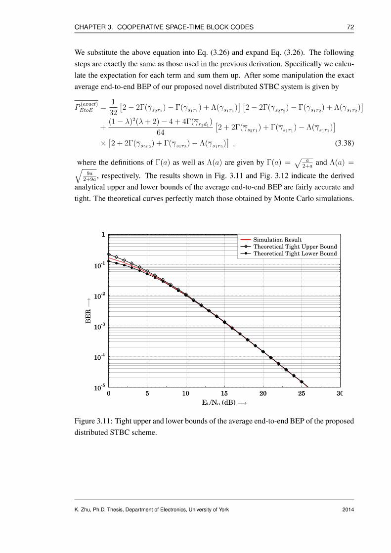
CHAPTER 3. COOPERATIVE SPACE-TIME BLOCK CODES 72
We substitute the above equation into Eq. (3.26) and expand Eq. (3.26). The followingsteps are exactly the same as those used in the previous derivation. Specifically we calcu-late the expectation for each term and sum them up. After some manipulation the exactaverage end-to-end BEP of our proposed novel distributed STBC system is given by
P(exact)EtoE =
1
32
[2− 2Γ(γs2r1)− Γ(γs1r1) + Λ(γs1r1)
] [2− 2Γ(γs2r2)− Γ(γs1r2) + Λ(γs1r2)
]
+(1− λ)2(λ+ 2)− 4 + 4Γ(γr1d1)
64
[2 + 2Γ(γs2r1) + Γ(γs1r1)− Λ(γs1r1)
]
×[2 + 2Γ(γs2r2) + Γ(γs1r2)− Λ(γs1r2)
], (3.38)
where the definitions of Γ(a) as well as Λ(a) are given by Γ(a) =√
a2+a
and Λ(a) =√9a
2+9a, respectively. The results shown in Fig. 3.11 and Fig. 3.12 indicate the derived
analytical upper and lower bounds of the average end-to-end BEP are fairly accurate andtight. The theoretical curves perfectly match those obtained by Monte Carlo simulations.
10-5
10-4
10-3
10-2
10-1
1
0 5 10 15 20 25 3010
-5
10-4
10-3
10-2
10-1
1
BER
0 5 10 15 20 25 30
Eb/N0 (dB)
Simulation Result
Theoretical Tight Upper Bound
Theoretical Tight Lower Bound
−→
−→
Figure 3.11: Tight upper and lower bounds of the average end-to-end BEP of the proposeddistributed STBC scheme.
K. Zhu, Ph.D. Thesis, Department of Electronics, University of York 2014

CHAPTER 3. COOPERATIVE SPACE-TIME BLOCK CODES 73
10-5
10-4
10-3
10-2
10-1
1
0 5 10 15 20 25 3010
-5
10-4
10-3
10-2
10-1
1
BER
0 5 10 15 20 25 30
Eb/N0 (dB)
Simulation Result
Theoretical Result
−→
−→
Figure 3.12: Exact average end-to-end BEP of the proposed distributed STBC scheme.
3.4 Conclusion
A novel distributed space-time block coding scheme using ‘decode-and-forward’ relayingprotocol for multi-relay assisted two-way cooperative communication is presented in thischapter. Some distinguished contributions of this scheme are summarized as follows:
• The network topology is similar to the one in [69] where two users simultaneouslyexchange Alamouti space-time coded signals via a relaying partner with the aidof PLNC, however we eliminate the constraint that the source nodes have to beequipped with multiple antennas. In this chapter, we show that our proposed schemecan still achieve full diversity order when each node acts as a single-antenna assistedmobile unit.
• A simple selection relaying or opportunistic relaying protocol is appropriately de-signed to effectively circumvent the error propagation inflicted by the relay nodes.More specifically, an error detection code (such as CRC) based selection relayingstrategy is proposed to retain the orthogonality of the distributed STBC codewordsas well as guarantee the full diversity order is achieved at the destination withoutemploying any sophisticated channel codes to protect the source-to-relay link.
• PLNC is employed to guarantee that the information exchange between two users
K. Zhu, Ph.D. Thesis, Department of Electronics, University of York 2014
CHAPTER 3. COOPERATIVE SPACE-TIME BLOCK CODES 74
via a single or multiple relays can be fulfilled within two time slots. Hence, thisnovel cooperative communication scheme for two-way relay channels can achievesignificant throughput and spectral efficiency improvements.
• Theoretical end-to-end bit error probability (BEP) performance of our proposeddistributed STBC scheme over two-way relay channel is investigated using the well-known MGF based approach. Tight upper and lower bounds of the average end-to-end BEP are first derived and solved. Then, the analysis is extended to obtain amore accurate expression of the exact BEP.
K. Zhu, Ph.D. Thesis, Department of Electronics, University of York 2014

Chapter 4
Cooperative Differential Space-TimeBlock Codes
Contents4.1 Cooperative Differential Space-Time Block Codes for Unidirec-
tional Relaying . . . . . . . . . . . . . . . . . . . . . . . . . . . . . . 76
4.2 Cooperative Differential Space-Time Block Codes for BidirectionalRelaying . . . . . . . . . . . . . . . . . . . . . . . . . . . . . . . . . 91
4.3 Conclusion . . . . . . . . . . . . . . . . . . . . . . . . . . . . . . . . 106
In the previous chapter, we focused on the discussion of distributed STBC scheme in thecontext of two-way cooperative communication. This chapter is devoted to the coopera-tive differential STBC (DSTBC) system under two-way relay scenario.
A novel distributed DSTBC structure is first studied, which enables construction ofDSTBC codewords from cooperation of multiple relaying partners at scattered geographiclocations in a distributed manner. We then apply the differential algorithm to the PLNCemployed in the two-way relaying network illustrated in Fig. 3.6 and propose a novellow-complexity differential PLNC, which also facilitates the extraction of information ofinterest from the superimposed signal at relay nodes, as for coherent PLNC but dispensingwith channel state information at the receiving side.
The proposed distributed DSTBC aided bidirectional relaying scheme is based on theframework developed in Chapter 3, where a similar selective relaying protocol is utilizedto guarantee the orthogonality of the distributed DSTBC codewords during the broadcast
K. Zhu, Ph.D. Thesis, Department of Electronics, University of York
752014
CHAPTER 4. COOPERATIVE DIFFERENTIAL SPACE-TIME BLOCK CODES 76
stage of two-way cooperative communication. Discussions in this chapter begin withan introduction of the distributed DSTBC scheme for unidirectional relay channels, andextend it to the bidirectional scenario in the following part of the chapter.
4.1 Cooperative Differential Space-Time Block Codes forUnidirectional Relaying
Modern telecommunication systems mostly concentrate on transmission of speech anddata using the star topology [84]. The trend of future wireless applications, for instancesmart grid and body area network, results in user cooperation among a large number ofbattery-powered network devices or communication nodes, following a peer-to-peer orheterogeneous mesh topology [84]. Consequently, data flowing in such configuration ismore likely to be forwarded in a relaying manner from node to node through the network.
Similar to the case for non-cooperative systems, fading or node failure could also lead tounreliable links in the relaying networks. Cooperative diversity [59, 61, 85] provided bymultiple cooperating users or nodes is capable of remedying the network instability andeffectively improving network robustness. It is possible to exploit further performancegain by implementing the concept of temporal and spatial diversity with the assistance ofdistributed DSTBC schemes. The maximum achievable diversity gain is identical to thatpromised in conventional multiple-antenna communication systems.
Under the circumstance that neither the transmitter nor the receiver has knowledge of thechannel coefficients, it is a preferable choice to incorporate differential encoding at thetransmitting side and non-coherent detection at the receiving side. Differential STBC forco-located multiple-antenna system was first introduced and investigated in [53]. It isdemonstrated in [53] that the unique properties of the DSTBC scheme significantly sim-plify the complexity of receiver and save precious spectrum resources otherwise requiredfor training-based channel estimation.
Motivated by the work in [86,87], we generalize and extend the principle of the distributedSTBC scheme to distributed DSTBC allowing non-coherent detection at the receiver. Ow-ing to the redundancy introduced during the differential encoding, it becomes feasible todetect the original information bits conveyed by the distributed DSTBC signal dispens-ing with the channels’ fading coefficients. On the other hand, the proposed distributedDSTBC scheme offers the same amount of spatial and temporal diversity gain as in the
K. Zhu, Ph.D. Thesis, Department of Electronics, University of York 2014
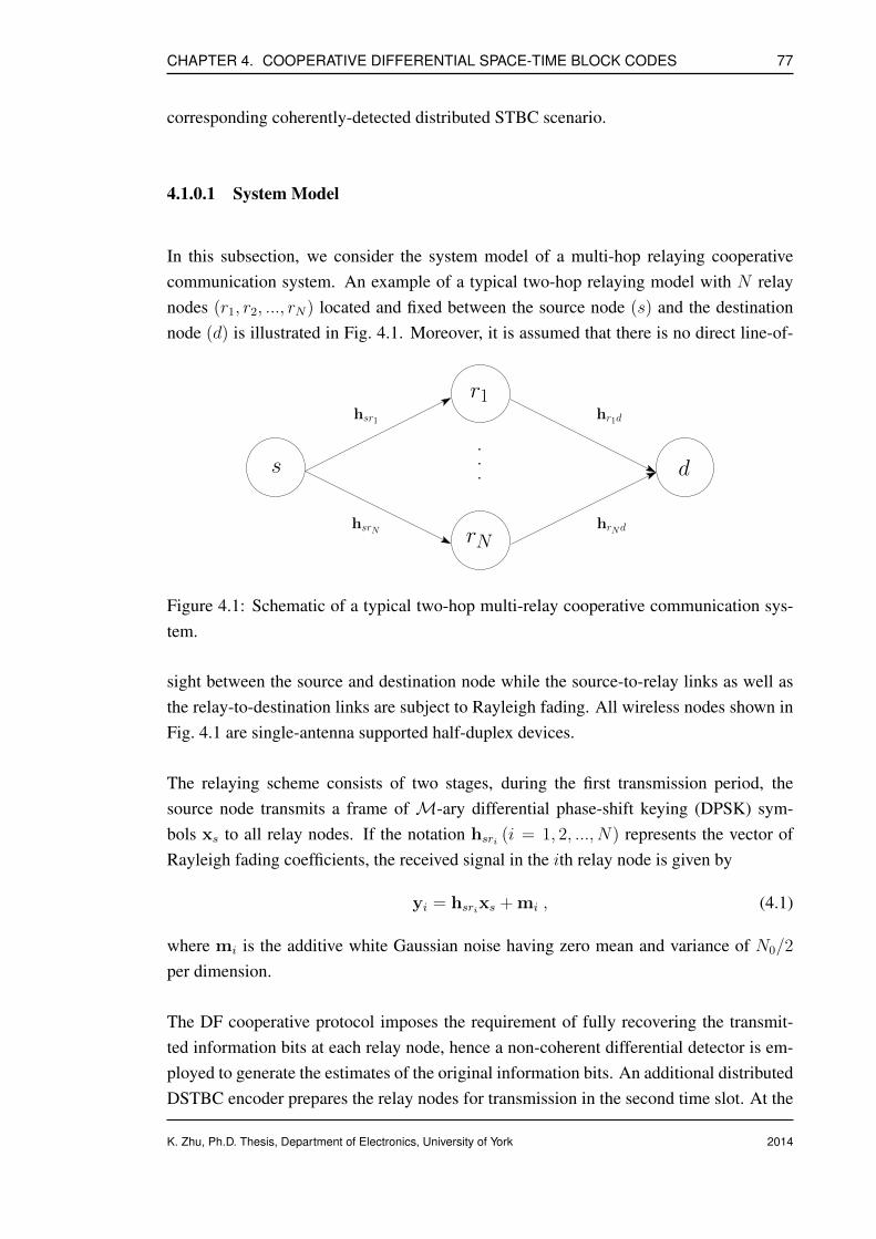
CHAPTER 4. COOPERATIVE DIFFERENTIAL SPACE-TIME BLOCK CODES 77
corresponding coherently-detected distributed STBC scenario.
4.1.0.1 System Model
In this subsection, we consider the system model of a multi-hop relaying cooperativecommunication system. An example of a typical two-hop relaying model with N relaynodes (r1, r2, ..., rN) located and fixed between the source node (s) and the destinationnode (d) is illustrated in Fig. 4.1. Moreover, it is assumed that there is no direct line-of-
s d
r1
rN
.
.
.
hr1d
hrNd
hsr1
hsrN
Figure 4.1: Schematic of a typical two-hop multi-relay cooperative communication sys-tem.
sight between the source and destination node while the source-to-relay links as well asthe relay-to-destination links are subject to Rayleigh fading. All wireless nodes shown inFig. 4.1 are single-antenna supported half-duplex devices.
The relaying scheme consists of two stages, during the first transmission period, thesource node transmits a frame of M-ary differential phase-shift keying (DPSK) sym-bols xs to all relay nodes. If the notation hsri (i = 1, 2, ..., N) represents the vector ofRayleigh fading coefficients, the received signal in the ith relay node is given by
yi = hsrixs + mi , (4.1)
where mi is the additive white Gaussian noise having zero mean and variance of N0/2
per dimension.
The DF cooperative protocol imposes the requirement of fully recovering the transmit-ted information bits at each relay node, hence a non-coherent differential detector is em-ployed to generate the estimates of the original information bits. An additional distributedDSTBC encoder prepares the relay nodes for transmission in the second time slot. At the
K. Zhu, Ph.D. Thesis, Department of Electronics, University of York 2014

CHAPTER 4. COOPERATIVE DIFFERENTIAL SPACE-TIME BLOCK CODES 78
destination node, a conventional DSTBC decoder is invoked to recover the informationbits from the received signal yd, which is expressed as
yd =N∑
i=1
hridvri + nd , (4.2)
where vri represents the distributed DSTBC symbols transmitted from the relay nodesduring the BC phase, whereas hrid indicates the Rayleigh block fading coefficients be-tween the ith relay node and the destination node whereas nd is the AWGN introduced atthe destination node having zero mean and variance of N0/2 per dimension.
4.1.0.2 Proposed Two-hop Cooperative DSTBC Scheme with Selection Relaying
A detailed block diagram of the proposed two-hop distributed DSTBC scheme with N =
2 relay nodes is demonstrated in Fig. 4.2.
Quasi
RayleighFading
Static
Source node
Quasi
RayleighFading
StaticDiff.
Decoder
STBC
Destination node
CRC
Relay node 1
Diff. PSKDetector
CRC
Relay node 2
Diff. PSKDetector
Diff.
Mod.
PSK
Distributed
DSTBC
Distributed
DSTBC
Figure 4.2: Schematic of the proposed two-hop distributed DSTBC aided unidirectionalcooperative communication scheme.
It is worth pointing out that, since the antenna array is constructed in a distributed fashion,it is unable to guarantee full diversity order at the destination if the re-encoded network-coded symbols are simply forwarded without certain protection mechanism. In order toenhance the error-resilience against potential error propagation, one popular solution isto protect the source-to-relay link by introducing redundancy using a channel code, withhigh decoding complexity at the relay nodes. A more appealing alternative is to invokea low-complexity frame-by-frame (or packet-by-packet) based relay selection strategy,similar to the one used in Section 3.2.2.2.
The negative effects of error propagation induced in the decoding and re-encoding stagecan now be effectively circumvented at each relay node. To elaborate further, a CRC
K. Zhu, Ph.D. Thesis, Department of Electronics, University of York 2014

CHAPTER 4. COOPERATIVE DIFFERENTIAL SPACE-TIME BLOCK CODES 79
error-detecting checksum is conducted prior to re-encoding the network-coded symbolsinto the distributed DSTBC frame. The generator polynomial for CRC is Γ = [x8 + x7 +
x4 + x3 + x + 1], which corresponds to the 9-bit string 110011011. Depending on theresults of CRC validation, each cooperating node can decide whether to become activeduring the second transmission period or just keep silent. For N = 2 relay nodes, thereare four different relaying scenarios summarized as follows in Tab. 4.1.
Table 4.1: Demonstration of the transmission schedule used in selective relaying for N =
2 relay nodes.
Relay 1 Relay 2 Transmission Mode
Pass Pass Distributed DSTBC
Pass Fail Differential PSK
Fail Pass Differential PSK
Fail Fail No transmission
4.1.0.3 Design of Distributed DSTBC Encoding and Decoding
In this subsection, we elaborate on the detailed encoding and decoding procedure of theproposed distributed DSTBC scheme, the schematic of which is illustrated in Fig. 4.3.
Several distributed DSTBC proposals from other contributors can be found in the liter-ature [88, 89] and references therein. It is noteworthy that existing techniques simplyincorporate conventional differential STBC in one or more cooperating nodes in order tosupport diversity reception at the destination, which requires multiple co-located antennasat relay nodes. On the contrary, our proposed scheme takes advantage of the distributednature inherent in the cooperative network allowing multiple single-antenna aided low-complexity low-power nodes to fully cooperate and exploit the same amount of spatialand temporal diversity gain.
The encoding procedure for the proposed distributed DSTBC scheme incorporating N =
2 relay nodes and a PSK signal constellation with 2L elements is stated as follows. Tobegin with, the encoding process is initialized by modulating the estimated informationbits at the ith relay node into a sequence of L-ary PSK symbols. For ease of presentation,
K. Zhu, Ph.D. Thesis, Department of Electronics, University of York 2014

CHAPTER 4. COOPERATIVE DIFFERENTIAL SPACE-TIME BLOCK CODES 80
V r1k
Delay
SymbolCalculateβ
Sr1k P r1
k
Cr1k−1
Cr1k
Distributed STBC
V r2k
SymbolCalculateβ
Sr2k P r2
k
Cr2k−1
Cr2k
Relay node 1
Relay node 2
Delay
(Cr1
k−1,−Cr1∗k
)
(Cr2
k−1, Cr2∗k
)
Figure 4.3: The schematic of the proposed distributed DSTBC encoder.
each pair of two adjacent PSK-modulated symbols is grouped into a block. To be morespecific, the kth block for the ith relay node is written as
Srik =[srik,1 srik,2
], (4.3)
where srik,1 and srik,2 represent the first and second element of Srik respectively.
For a given complex-valued set P consisting of 22L distinct 1× 2 coefficient vectors, theinput symbols at the ith relay node are mapped onto the constellation P , where the firstand second element of the resultant coefficient vector corresponding to the kth block atthe ith relay node are denoted as P ri
k =[prik,1 prik,2
]. The design of the mapping function
β is arbitrary as long as all coefficient vectors in P are unique and a one-to-one mappingis guaranteed. In this work, an orthogonal mapping function is employed, which gives
prik,1 = srik,1 (sri0 )∗ + srik,2 (sri1 )∗ , (4.4)
prik,2 = −srik,1sri1 + srik,2sri0 , (4.5)
where sri0 and sri1 are the notations for the first and second element of the reference blockat the ith relay node.
An example of the one-to-one mapping function β and the complex-valued finite set P isdemonstrated as follows. Assume the PSK constellation consists of two points 1/
√2 and
K. Zhu, Ph.D. Thesis, Department of Electronics, University of York 2014

CHAPTER 4. COOPERATIVE DIFFERENTIAL SPACE-TIME BLOCK CODES 81
−1/√
2 and the set P is defined as P = (1, 0), (0, 1), (0,−1), (−1, 0). The encodingcommences from the transmission of a pair of arbitrary reference symbols sri0 as well assri1 which do not carry any information. The orthogonal mapping β maps a block of twoinput bits onto P using Eq. (4.4) and Eq. (4.5). As a result, the one-to-one relationshipbetween input data bits and coefficient vector P ri
k is summarized in Tab. 4.2 below.
Table 4.2: Demonstration of computing coefficient vectors P rik for given input data bits.
Input data bits P rik = [prik,1 prik,2]
(0 0) (1 0)
(0 1) (0 -1)
(1 0) (0 1)
(1 1) (-1 0)
At time interval k, each relay node calculates a 1×2 differential codeword vector, denotedby Cri
k , in a recursive fashion. The corresponding differential symbols depend on the onegenerated in the previous block at time k − 1, mathematically speaking
Crik = prik,1O1(Srik−1) + prik,2O2(Srik−1) , (4.6)
where O1(Srik−1) and O2(Srik−1) are two vectors constructed on an orthogonal basis
O1(Srik−1) = Srik =[srik,1 srik,2
], (4.7)
O2(Srik−1) =[(srik,2)∗ −
(srik,1)∗]
. (4.8)
Subsequently, a distributed Alamouti STBC encoder is invoked to generate the distributedDSTBC codewords V r1
k =[cr1k,1 −
(cr1k,2)∗] for the kth block transmitted by the first
relay node, whilst V r2k =
[cr2k,1
(cr2k,2)∗] is transmitted by the second relay node.
4.1.0.4 Performance Results and Discussion
The BER performance of the proposed selection relaying aided DPSK-DDSTBC schemefor the unidirectional relaying scenario is examined and quantified using Monte-Carlosimulation as shown in Fig. 4.4 and Fig. 4.5. It is assumed that the number ofDPSK/distributed DSTBC symbols used for transmission from the source/relay node is
K. Zhu, Ph.D. Thesis, Department of Electronics, University of York 2014
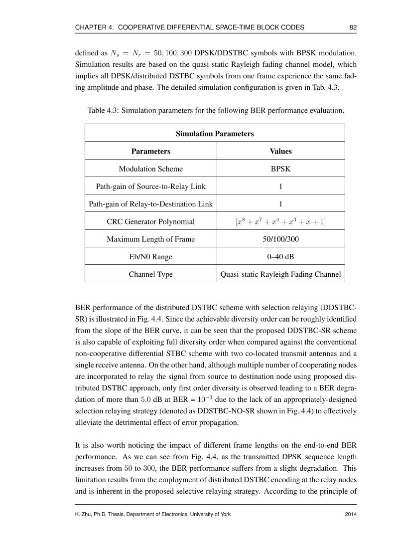
CHAPTER 4. COOPERATIVE DIFFERENTIAL SPACE-TIME BLOCK CODES 82
defined as Ns = Nr = 50, 100, 300 DPSK/DDSTBC symbols with BPSK modulation.Simulation results are based on the quasi-static Rayleigh fading channel model, whichimplies all DPSK/distributed DSTBC symbols from one frame experience the same fad-ing amplitude and phase. The detailed simulation configuration is given in Tab. 4.3.
Table 4.3: Simulation parameters for the following BER performance evaluation.
Simulation Parameters
Parameters Values
Modulation Scheme BPSK
Path-gain of Source-to-Relay Link 1
Path-gain of Relay-to-Destination Link 1
CRC Generator Polynomial [x8 + x7 + x4 + x3 + x+ 1]
Maximum Length of Frame 50/100/300
Eb/N0 Range 0–40 dB
Channel Type Quasi-static Rayleigh Fading Channel
BER performance of the distributed DSTBC scheme with selection relaying (DDSTBC-SR) is illustrated in Fig. 4.4. Since the achievable diversity order can be roughly identifiedfrom the slope of the BER curve, it can be seen that the proposed DDSTBC-SR schemeis also capable of exploiting full diversity order when compared against the conventionalnon-cooperative differential STBC scheme with two co-located transmit antennas and asingle receive antenna. On the other hand, although multiple number of cooperating nodesare incorporated to relay the signal from source to destination node using proposed dis-tributed DSTBC approach, only first order diversity is observed leading to a BER degra-dation of more than 5.0 dB at BER = 10−3 due to the lack of an appropriately-designedselection relaying strategy (denoted as DDSTBC-NO-SR shown in Fig. 4.4) to effectivelyalleviate the detrimental effect of error propagation.
It is also worth noticing the impact of different frame lengths on the end-to-end BERperformance. As we can see from Fig. 4.4, as the transmitted DPSK sequence lengthincreases from 50 to 300, the BER performance suffers from a slight degradation. Thislimitation results from the employment of distributed DSTBC encoding at the relay nodesand is inherent in the proposed selective relaying strategy. According to the principle of
K. Zhu, Ph.D. Thesis, Department of Electronics, University of York 2014
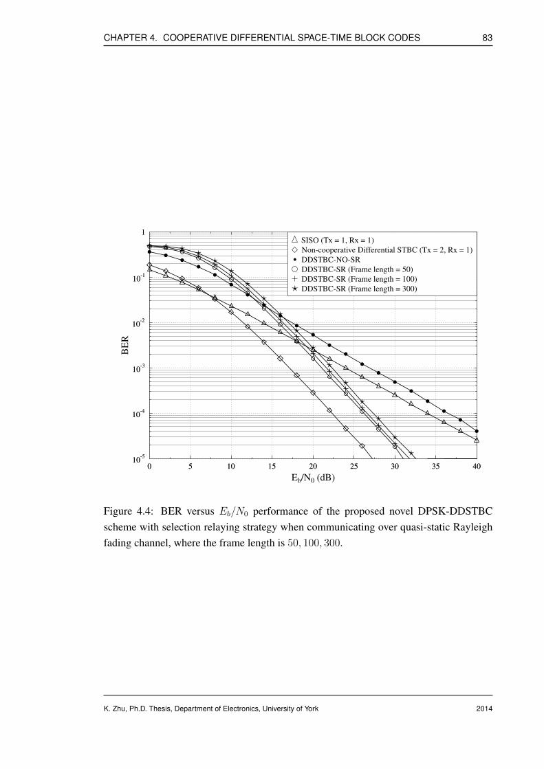
CHAPTER 4. COOPERATIVE DIFFERENTIAL SPACE-TIME BLOCK CODES 83
10-5
10-4
10-3
10-2
10-1
1
0 5 10 15 20 25 30 35 40
. . . . . . . . . . . . . . . . . . . . .10
-5
10-4
10-3
10-2
10-1
1
BER
0 5 10 15 20 25 30 35 40
Eb/N0 (dB)
SISO (Tx = 1, Rx = 1)
Non-cooperative Differential STBC (Tx = 2, Rx = 1). DDSTBC-NO-SR
DDSTBC-SR (Frame length = 50)
DDSTBC-SR (Frame length = 100)
DDSTBC-SR (Frame length = 300)
Figure 4.4: BER versus Eb/N0 performance of the proposed novel DPSK-DDSTBCscheme with selection relaying strategy when communicating over quasi-static Rayleighfading channel, where the frame length is 50, 100, 300.
K. Zhu, Ph.D. Thesis, Department of Electronics, University of York 2014
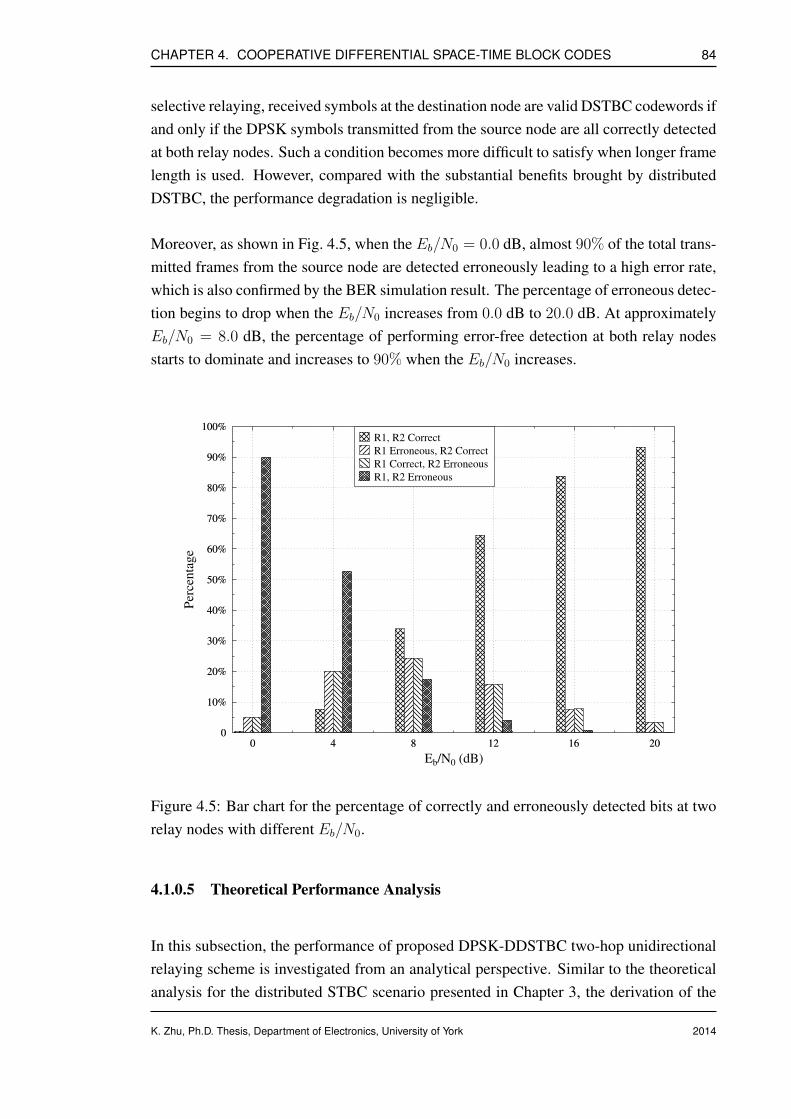
CHAPTER 4. COOPERATIVE DIFFERENTIAL SPACE-TIME BLOCK CODES 84
selective relaying, received symbols at the destination node are valid DSTBC codewords ifand only if the DPSK symbols transmitted from the source node are all correctly detectedat both relay nodes. Such a condition becomes more difficult to satisfy when longer framelength is used. However, compared with the substantial benefits brought by distributedDSTBC, the performance degradation is negligible.
Moreover, as shown in Fig. 4.5, when the Eb/N0 = 0.0 dB, almost 90% of the total trans-mitted frames from the source node are detected erroneously leading to a high error rate,which is also confirmed by the BER simulation result. The percentage of erroneous detec-tion begins to drop when the Eb/N0 increases from 0.0 dB to 20.0 dB. At approximatelyEb/N0 = 8.0 dB, the percentage of performing error-free detection at both relay nodesstarts to dominate and increases to 90% when the Eb/N0 increases.
0
10%
20%
30%
40%
50%
60%
70%
80%
90%
100%
0 4 8 12 16 200
10%
20%
30%
40%
50%
60%
70%
80%
90%
100%
Percentage
0 4 8 12 16 20
Eb/N0 (dB)
R1, R2 Correct
R1 Erroneous, R2 Correct
R1 Correct, R2 Erroneous
R1, R2 Erroneous
Figure 4.5: Bar chart for the percentage of correctly and erroneously detected bits at tworelay nodes with different Eb/N0.
4.1.0.5 Theoretical Performance Analysis
In this subsection, the performance of proposed DPSK-DDSTBC two-hop unidirectionalrelaying scheme is investigated from an analytical perspective. Similar to the theoreticalanalysis for the distributed STBC scenario presented in Chapter 3, the derivation of the
K. Zhu, Ph.D. Thesis, Department of Electronics, University of York 2014

CHAPTER 4. COOPERATIVE DIFFERENTIAL SPACE-TIME BLOCK CODES 85
average end-to-end error probability based on the moment generating function is straight-forward and intuitive.
Since the analysis methodology is very similar to that used in Section 3.3, the deriva-tion steps are described in brief in order to keep the presentation concise and compact.The instantaneous end-to-end BEP measured at the destination node, denoted by Pb,EtoE ,consists of four parts depending on the different statuses of selective relaying during thecooperating stage, which are summarized in Tab. 4.1. It is straightforward to define theinstantaneous end-to-end BEP Pb,EtoE with the following formula
Pb,EtoE = (1− P r1F,DPSK)(1− P r2
F,DPSK)Pb,DSTBC︸ ︷︷ ︸r1, r2 both decode correctly
+ (1− P r1F,DPSK)P r2
F,DPSKPb,DPSK︸ ︷︷ ︸r1 decodes correctly, r2 decodes erroneously
+ P r1F,DPSK(1− P r2
F,DPSK)Pb,DPSK︸ ︷︷ ︸r1 decodes erroneously, r2 decodes correctly
+1
2P r1F,DPSKP
r2F,DPSK
︸ ︷︷ ︸r1, r2 both decode erroneously
, (4.9)
where the notations used in Eq. (4.9) are explained as follows:
• To begin with, the term P riF,DPSK(i = 1, 2) denotes the frame error rate of the
received DPSK signal measured at the ith relay node, which is used to indicate theprobability of whether one specific DPSK frame transmitted from the source nodeis correctly detected at the ith relay node.
• Assume both relay nodes r1, r2 succeed in making correct detection, a frame ofdistributed DSTBC symbols are transmitted to the destination node at the secondhop. Pb,DSTBC represents the instantaneous BEP of the received distributed DSTBCsignal estimated at the destination node.
• If the estimation of DPSK signal is erroneous at either of the relay nodes r1, r2, theperformance of the relay-to-destination link is identical to that of DPSK schemeproviding only first order diversity as the diversity reception would fail when onlyone row or one column of the DSTBC codewords arrive at the destination node.Therefore, Pb,DPSK is used to denote the instantaneous BEP of the received signalfor the scenario of only one relay node is activated.
• In the last scenario, none of the relay nodes r1, r2 detects the DPSK symbol se-quence successfully, which results in complete radio silence during the secondtransmission period. Destination node has to pick an arbitrary pair of binary bits asthe estimation. Hence, this leads to a bit error rate of 1/2 as observed in Eq. (4.9).
K. Zhu, Ph.D. Thesis, Department of Electronics, University of York 2014
CHAPTER 4. COOPERATIVE DIFFERENTIAL SPACE-TIME BLOCK CODES 86
The frame error probability of receiving K number of sequential DPSK symbols is givenby [16]
P riF,DPSK = 1− (
1
2)K
[1 +
K∑
k=1
k∏
j=1
K + 1− jj + 1
γi
], (4.10)
where we have i = 1, 2 in this work since two relay nodes are considered in the networktopology and γi is the average received SNR at the ith relay node.
On the other hand, the bit error probability of the differential STBC scheme Pb,DSTBCwith non-coherent detection is studied in [27] and can be expressed as
Pb,DSTBC = λ2 [1 + 2(1− λ)] , λ =1
2− 1
2
(1 +
1
γ
)−1/2
, (4.11)
where γ denotes the average received SNR at the destination node.
Moreover, the bit error probability of receiving a frame of DPSK symbols with non-coherent detection at the destination node can be easily obtained by letting the framelength K = 1 and replacing γi with γ, which yields
Pb,DPSK =1
2(1 + γ). (4.12)
Finally, the average end-to-end bit error probability of the novel unidirectional distributedDSTBC relaying scheme is acquired by calculating the statistical expectation of the in-stantaneous end-to-end BEP, where the expectation is conditioned on the distribution ofthe fading channel, which gives
Pb,EtoE = E[Pb,EtoE
]. (4.13)
A closed-form expression is difficult to find for Eq. (4.13), hence the well-known numer-ical integration approach is employed to evaluate the expectation of Eq. (4.13). The ana-lytical evaluation of the average end-to-end bit error probability of the proposed DPSK-DDSTBC scheme is plotted and verified against the simulation results for different framelengths as illustrated in Fig. 4.6.
K. Zhu, Ph.D. Thesis, Department of Electronics, University of York 2014

CHAPTER 4. COOPERATIVE DIFFERENTIAL SPACE-TIME BLOCK CODES 87
Figure 4.6: Comparison of the analytical and empirical average end-to-end BEP of theproposed DPSK-DDSTBC unidirectional relaying scheme with different frame lengths.
K. Zhu, Ph.D. Thesis, Department of Electronics, University of York 2014
CHAPTER 4. COOPERATIVE DIFFERENTIAL SPACE-TIME BLOCK CODES 88
4.1.0.6 Extension to Turbo-coded Distributed DSTBC Scheme
In the previous subsection, we proposed and investigated a novel distributed DPSK-DSTBC two-hop relaying scheme for unidirectional cooperative communications. Ob-servations from analytical and empirical results both confirm the fact that the bit errorperformance of the proposed distributed scheme varies with respect to the frame length.The likelihood of making correct detection for the received DPSK symbol sequence atthe relay nodes becomes smaller if longer frame length is involved in the source-to-relaylink. As a result, implementation of the proposed scheme is constrained by this undesir-able property in practice.
The practical limitation is circumvented by incorporating a certain level of temporal re-dundancy using FEC codes in order to reinforce the reliability of the source-to-relay link.Moreover, the error rate degradation of an uncoded distributed DSTBC lacking sufficientprotection is proportional to the frame length. Fortunately, the coding gain associated tothe FEC codes also grows as an increasing number of information bits are encoded pro-viding a higher level of redundancy. Hence, the employment of FEC codes in the sourcenode offers an efficient and effective countermeasure.
In this subsection, a half-rate Turbo-coded DPSK scheme is introduced for suppressingthe sensitivity to the frame length. To elaborate further, a quadratic polynomial permu-tation (QPP) interleaver [90, 91], which has been standardized into the 3GPP LTE spec-ification, is considered as the internal interleaver for the Turbo code at the source node;whereas a random block interleaver is employed at both source and relay nodes to fullyscramble the coded symbols and eliminate the correlation between adjacent symbols. AQPP interleaver defines the relationship between the output bit index i and the input indexπ(i), which satisfies the following equation
π(i) =(f1i+ f2i
3)
modK , (4.14)
where K is the block size, f1 and f2 are the coefficients that characterize the rule ofpermutation. For example, if block size K = 1088, coefficients f1 and f2 are given in3GPP technical specification [92] as follows: f1 = 171; f2 = 204; while K = 3072,f1 = 47; f2 = 96.
The schematic of the Turbo-coded DPSK-DDSTBC scheme with selection relaying strat-egy for one-way relaying case is depicted in Fig. 4.7, in which it is assumed that twosingle-antenna assisted relay nodes (i = 1, 2) are situated between the source and des-tination node.
K. Zhu, Ph.D. Thesis, Department of Electronics, University of York 2014
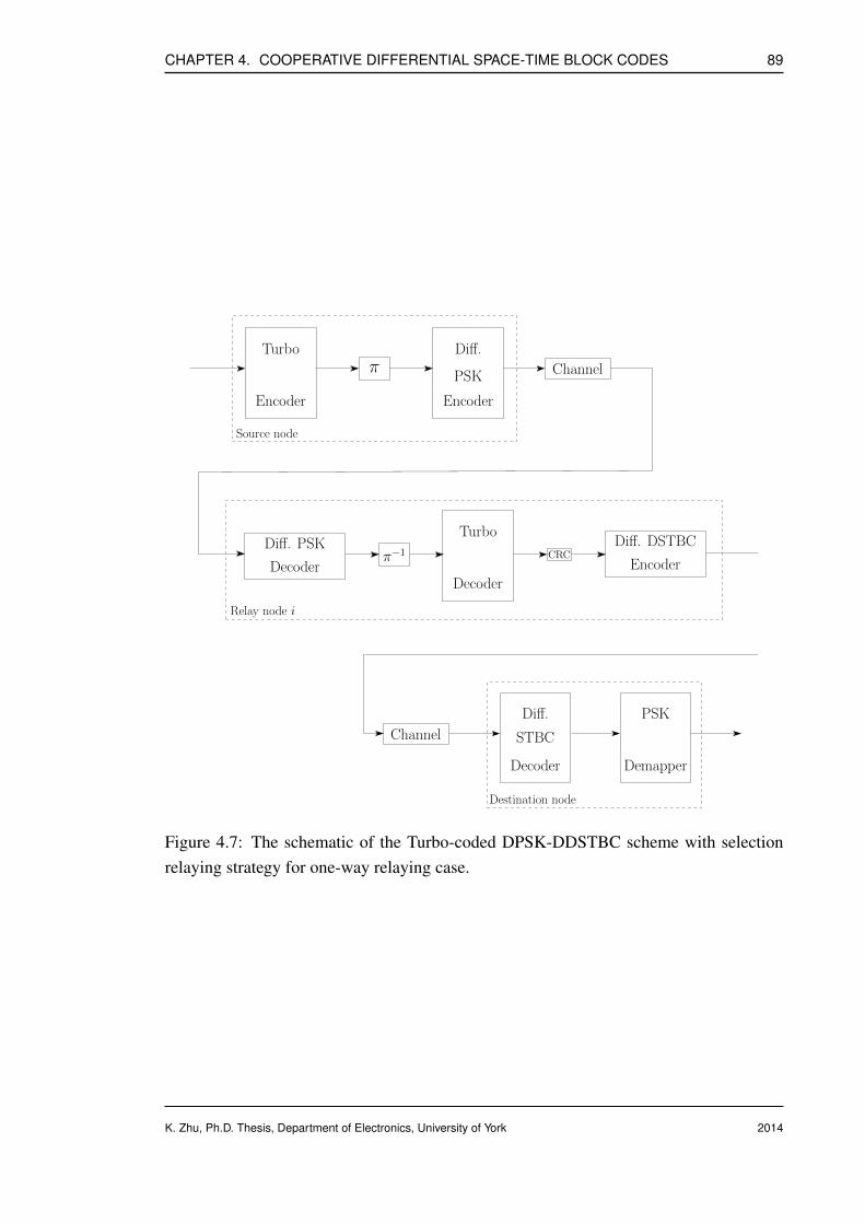
CHAPTER 4. COOPERATIVE DIFFERENTIAL SPACE-TIME BLOCK CODES 89
Diff. PSK
Decoder
Diff. DSTBC
Encoderπ−1
Turbo
Decoder
CRC
Relay node i
Diff.
Encoder
PSK Channel
Source node
πTurbo
Encoder
Diff.
Decoder
STBC
PSK
Demapper
Destination node
Channel
Figure 4.7: The schematic of the Turbo-coded DPSK-DDSTBC scheme with selectionrelaying strategy for one-way relaying case.
K. Zhu, Ph.D. Thesis, Department of Electronics, University of York 2014
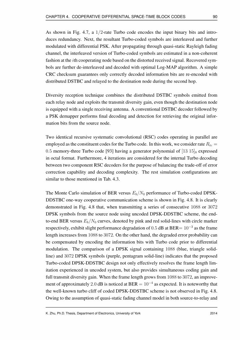
CHAPTER 4. COOPERATIVE DIFFERENTIAL SPACE-TIME BLOCK CODES 90
As shown in Fig. 4.7, a 1/2-rate Turbo code encodes the input binary bits and intro-duces redundancy. Next, the resultant Turbo-coded symbols are interleaved and furthermodulated with differential PSK. After propagating through quasi-static Rayleigh fadingchannel, the interleaved version of Turbo-coded symbols are estimated in a non-coherentfashion at the ith cooperating node based on the distorted received signal. Recovered sym-bols are further de-interleaved and decoded with optimal Log-MAP algorithm. A simpleCRC checksum guarantees only correctly decoded information bits are re-encoded withdistributed DSTBC and relayed to the destination node during the second hop.
Diversity reception technique combines the distributed DSTBC symbols emitted fromeach relay node and exploits the transmit diversity gain, even though the destination nodeis equipped with a single receiving antenna. A conventional DSTBC decoder followed bya PSK demapper performs final decoding and detection for retrieving the original infor-mation bits from the source node.
Two identical recursive systematic convolutional (RSC) codes operating in parallel areemployed as the constituent codes for the Turbo code. In this work, we consider rateRtc =
0.5 memory-three Turbo code [93] having a generator polynomial of [13 15]8 expressedin octal format. Furthermore, 4 iterations are considered for the internal Turbo decodingbetween two component RSC decoders for the purpose of balancing the trade-off of errorcorrection capability and decoding complexity. The rest simulation configurations aresimilar to those mentioned in Tab. 4.3.
The Monte Carlo simulation of BER versus Eb/N0 performance of Turbo-coded DPSK-DDSTBC one-way cooperative communication scheme is shown in Fig. 4.8. It is clearlydemonstrated in Fig. 4.8 that, when transmitting a series of consecutive 1088 or 3072
DPSK symbols from the source node using uncoded DPSK-DDSTBC scheme, the end-to-end BER versus Eb/N0 curves, denoted by pink and red solid-lines with circle markerrespectively, exhibit slight performance degradation of 0.5 dB at BER= 10−3 as the framelength increases from 1088 to 3072. On the other hand, the degraded error probability canbe compensated by encoding the information bits with Turbo code prior to differentialmodulation. The comparison of a DPSK signal containing 1088 (blue, triangle solid-line) and 3072 DPSK symbols (purple, pentagram solid-line) indicates that the proposedTurbo-coded DPSK-DDSTBC design not only effectively resolves the frame length lim-itation experienced in uncoded system, but also provides simultaneous coding gain andfull transmit diversity gain. When the frame length grows from 1088 to 3072, an improve-ment of approximately 2.0 dB is noticed at BER = 10−4 as expected. It is noteworthy thatthe well-known turbo cliff of coded DPSK-DDSTBC scheme is not observed in Fig. 4.8.Owing to the assumption of quasi-static fading channel model in both source-to-relay and
K. Zhu, Ph.D. Thesis, Department of Electronics, University of York 2014

CHAPTER 4. COOPERATIVE DIFFERENTIAL SPACE-TIME BLOCK CODES 91
relay-to-destination links, stringent limitation is imposed on the available coding gainprovided by the channel codes including Turbo code, due to lack of time diversity.
Figure 4.8: BER versus Eb/N0 performance of the Turbo-coded distributed DSTBCscheme with selection relaying strategy when communicating over quasi-static Rayleighfading channel.
4.2 Cooperative Differential Space-Time Block Codes forBidirectional Relaying
In the previous subsection, we investigated a fully non-coherent distributed differentialSTBC scheme in the context of two-hop unidirectional cooperative communication. Al-though the decoding and detection at both relay and destination nodes are independentwith channel’s fading coefficients, it is still capable of attaining full transmit diversitygain. In this subsection, we take one step further by extending the unidirectional DPSK-DDSTBC scheme to bidirectional relaying scenario.
K. Zhu, Ph.D. Thesis, Department of Electronics, University of York 2014
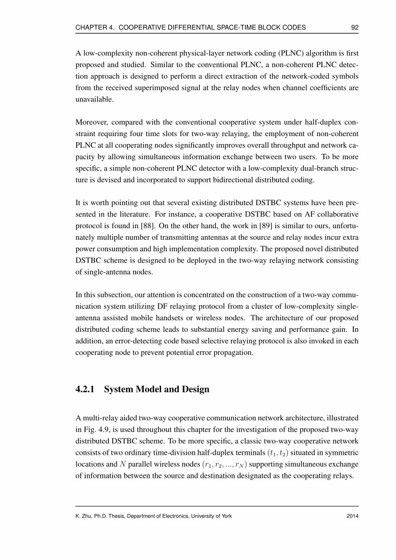
CHAPTER 4. COOPERATIVE DIFFERENTIAL SPACE-TIME BLOCK CODES 92
A low-complexity non-coherent physical-layer network coding (PLNC) algorithm is firstproposed and studied. Similar to the conventional PLNC, a non-coherent PLNC detec-tion approach is designed to perform a direct extraction of the network-coded symbolsfrom the received superimposed signal at the relay nodes when channel coefficients areunavailable.
Moreover, compared with the conventional cooperative system under half-duplex con-straint requiring four time slots for two-way relaying, the employment of non-coherentPLNC at all cooperating nodes significantly improves overall throughput and network ca-pacity by allowing simultaneous information exchange between two users. To be morespecific, a simple non-coherent PLNC detector with a low-complexity dual-branch struc-ture is devised and incorporated to support bidirectional distributed coding.
It is worth pointing out that several existing distributed DSTBC systems have been pre-sented in the literature. For instance, a cooperative DSTBC based on AF collaborativeprotocol is found in [88]. On the other hand, the work in [89] is similar to ours, unfortu-nately multiple number of transmitting antennas at the source and relay nodes incur extrapower consumption and high implementation complexity. The proposed novel distributedDSTBC scheme is designed to be deployed in the two-way relaying network consistingof single-antenna nodes.
In this subsection, our attention is concentrated on the construction of a two-way commu-nication system utilizing DF relaying protocol from a cluster of low-complexity single-antenna assisted mobile handsets or wireless nodes. The architecture of our proposeddistributed coding scheme leads to substantial energy saving and performance gain. Inaddition, an error-detecting code based selective relaying protocol is also invoked in eachcooperating node to prevent potential error propagation.
4.2.1 System Model and Design
A multi-relay aided two-way cooperative communication network architecture, illustratedin Fig. 4.9, is used throughout this chapter for the investigation of the proposed two-waydistributed DSTBC scheme. To be more specific, a classic two-way cooperative networkconsists of two ordinary time-division half-duplex terminals (t1, t2) situated in symmetriclocations and N parallel wireless nodes (r1, r2, ..., rN) supporting simultaneous exchangeof information between the source and destination designated as the cooperating relays.
K. Zhu, Ph.D. Thesis, Department of Electronics, University of York 2014
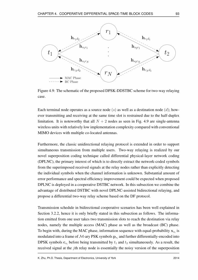
CHAPTER 4. COOPERATIVE DIFFERENTIAL SPACE-TIME BLOCK CODES 93
t1 t2
r1
rN
.
.
.
hs2r1
hr1d1
hs2rN
hrNd1
hs1r1
hr1d2
hs1rN
hrNd2
MAC PhaseBC Phase
Figure 4.9: The schematic of the proposed DPSK-DDSTBC scheme for two-way relayingcase.
Each terminal node operates as a source node (s) as well as a destination node (d); how-ever transmitting and receiving at the same time slot is restrained due to the half-duplexlimitation. It is noteworthy that all N + 2 nodes as seen in Fig. 4.9 are single-antennawireless units with relatively low implementation complexity compared with conventionalMIMO devices with multiple co-located antennas.
Furthermore, the classic unidirectional relaying protocol is extended in order to supportsimultaneous transmission from multiple users. Two-way relaying is realized by ournovel superposition coding technique called differential physical-layer network coding(DPLNC), the primary interest of which is to directly extract the network-coded symbolsfrom the superimposed received signals at the relay nodes rather than explicitly detectingthe individual symbols when the channel information is unknown. Substantial amount oferror performance and spectral efficiency improvement could be expected when proposedDPLNC is deployed in a cooperative DSTBC network. In this subsection we combine theadvantage of distributed DSTBC with novel DPLNC-assisted bidirectional relaying, andpropose a differential two-way relay scheme based on the DF protocol.
Transmission schedule in bidirectional cooperative scenarios has been well explained inSection 3.2.2, hence it is only briefly stated in this subsection as follows. The informa-tion emitted from one user takes two transmission slots to reach the destination via relaynodes, namely the multiple access (MAC) phase as well as the broadcast (BC) phase.To begin with, during the MAC phase, information sequence with equal-probability xsi ismodulated into a frame ofM-ary PSK symbols psi and further differentially-encoded intoDPSK symbols csi before being transmitted by t1 and t2 simultaneously. As a result, thereceived signal at the jth relay node is essentially the noisy version of the superposition
K. Zhu, Ph.D. Thesis, Department of Electronics, University of York 2014

CHAPTER 4. COOPERATIVE DIFFERENTIAL SPACE-TIME BLOCK CODES 94
of two channel-corruptedM-DPSK signals, which is written as
yrj =2∑
i=1
(hsirjcsi
)+ vrj , (4.15)
where j ∈ 1, 2, . . . , N and hsirj is the Rayleigh block fading coefficients of the trans-mission link between the ith source node and the jth relay node implying that L sym-bols in one block are subject to the same Rayleigh fading. Moreover, vrj denotes thecomplex-valued AWGN imposed at the jth relay node with zero mean and varianceσ2I = σ2
Q = N0/2 for both real and imaginary part.
Information bits transmitted from the ith source node could be estimated at the jth relaynode, denoted as x
(rj)si , by treating signals from other source as interference. Therefore,
the corresponding network-coded symbols are defined as
urj = x(rj)s1⊕ x(rj)
s2, (4.16)
where ⊕ indicates an element-by-element modulo-two addition performed in the Galoisfield GF(2m), which can be simplified to the exclusive or arithmetic when m = 1. For-tunately, after the advent of differential PLNC, calculation of the network-coded symbolsurj becomes more efficient, since differential PLNC is able to generate correspondingnetwork-coded symbols immediately from the superimposed signal yrj . Due to the differ-ential feature, the generation of network-coded symbols is implemented in a non-coherentfashion and is independent of the availability of channel coefficients. The detailed princi-ple of differential PLNC is elaborated in following subsection.
During the BC phase, only correctly estimated network-coded symbols are re-encodedinto distributed DSTBC symbols wrj and broadcasted to the destination nodes. Althougheach cooperating relay node only carries one row of the DSTBC code matrix, the com-bined received signals at the destination nodes are still valid DSTBC codewords. Thereceived signal at the ith destination node can be expressed as:
ydi =N∑
j=1
(hrjdiwrj
)+ vdi , (4.17)
where i ∈ 1, 2 and hrjdi denotes the complex-valued Rayleigh block fading coeffi-cients of the channel between the jth relay node and the ith destination node, while vdirepresents the AWGN induced at the ith destination node with zero mean and varianceσ2I = σ2
Q = N0/2. It is noteworthy that the overall transmit power for the relay-to-destination link is normalized so that the average energy of the distributed DSTBC code-words is
∑Nj=1 |wrj |2 = 1.
K. Zhu, Ph.D. Thesis, Department of Electronics, University of York 2014
CHAPTER 4. COOPERATIVE DIFFERENTIAL SPACE-TIME BLOCK CODES 95
Relay node i
CRCDiff. DSTBC
Encoder
Diff. PLNCDetector
Diff.
Decoder
STBC
Destination node
PSK
Demapper
PLNC
Demapper
Figure 4.10: System structure for the differential PLNC aided two-way DPSK-DDSTBCscheme.
At the destination node, a conventional differential STBC decoder as proposed in [53] isinvoked to obtain the estimate of the network-coded symbols urj . Applying the exclusive-or arithmetic again between the estimated network-coded symbols and the informationbits transmitted at the MAC phase so that each destination node is capable of retrievingthe interested information transmitted from the source node by
xs1 = urj ⊕ xs2 . (4.18)
Similarly, for the information bits transmitted from s2, we have:
xs2 = urj ⊕ xs1 , (4.19)
where j ∈ 1, 2, . . . , N. Owing to the linearity of the cyclic codes, each relay node iscapable of distinguishing the integrity of the network-coded symbols generated from yrjby comparing the CRC of urj with the ‘modulo-two sum’ of two CRCs correspondingto the information streams xs1 and xs2 from the source nodes. In other words, if theestimated information sequences pass the same CRC with identical generator polynomial,their modulo-two sum at the relay nodes will also pass. On the other hand, when one isin error, or both are in error but in different positions, the check will fail.
K. Zhu, Ph.D. Thesis, Department of Electronics, University of York 2014
CHAPTER 4. COOPERATIVE DIFFERENTIAL SPACE-TIME BLOCK CODES 96
4.2.1.1 Differential Physical-layer Network Coding for Two-way Fading Channel
The principle and design procedure of the novel non-coherent or differential PLNC iselaborated and studied in this subsection. Non-coherent PLNC is evolved from the classiccoherent PLNC with the same objective, that is to support bidirectional communicationand recover the spectral efficiency loss caused by half-duplex constraint by calculating thenetwork-coded symbols directly from the linear superposition of multiple complex-valuedsignals from source nodes.
One of the major limitations regarding the existing coherently-detected PLNC schemesis the requirement of prior knowledge of the channel state information at each receivingnode. In general, the problem of accurate estimation of fading channel coefficients issolved by inserting pilot symbols periodically, which leads to spectral efficiency loss.
The contrivance of the novel non-coherent PLNC has drawn the inspiration from the dif-ferential demodulation, in which the channel information estimation is avoided by takingadvantage of the connection between two adjacent symbols and processing the receivedsignal successively.
Two similar research works on non-coherent transmission schemes for two-way relaychannels are proposed recently in [94, 95]. However, existing schemes are less appeal-ing in practice as a sophisticated ML-based sequence estimation is used to extract thenetwork-coded symbols at each relay node inflicting high computational complexity. Fur-thermore, a Turbo-coded differential PLNC system utilizing frequency shift keying (FSK)modulation is presented in [96]. Although this scheme is less complex than [94,95], FSKsuffers from bandwidth inefficiency making it also less attractive in practice.
For ease of analysis, it is assumed that 2-level DBPSK modulation is invoked at twosource nodes. Letting the differential encoding at the ith source node is initialized bythe reference symbol vsi [0] = +1, the received signal at the jth relay node is apparentlythe superposition of two DBPSK-modulated symbol sequences. For a DBPSK-modulatedsignal, there are three possible phasor combinations described as Λ = (vs1 + vs2) ∈ τ ,where τ = −2, 0,+2 for the case hs1rj = hs2rj = 1. As mentioned earlier, the principleof non-coherent PLNC relies on exploiting the dependence between the current receivedsymbol and the previous one. The connection between the superimposed signal yrj andthe desired network-coded symbols urj is listed in Tab. 4.4.
After careful analysis of Tab. 4.4, the non-coherent PLNC decision rule is generalized asfollows. The network-coded symbol at time instant T is uniquely defined by the modulus
K. Zhu, Ph.D. Thesis, Department of Electronics, University of York 2014

CHAPTER 4. COOPERATIVE DIFFERENTIAL SPACE-TIME BLOCK CODES 97
Table 4.4: An example of non-coherent PLNC for detecting two superimposed DBPSK-modulated symbol sequences. The reference symbols for s1 and s2 are assumed to be[+1,+1], and it is assumed that hs1rj = hs2rj = 1.
Info. Bit Diff. Symbol yrj Network-coded
xs1 xs2 vs1 vs2 Symbol urjTime T 0 0 +1 +1 +2 0
0 0 +1 +1 +2 0
Time 0 1 +1 -1 0 1
T + 1 1 0 -1 +1 0 1
1 1 -1 -1 -2 0
Time T 0 1 +1 -1 0 1
0 0 +1 -1 0 0
Time 0 1 +1 +1 +2 1
T + 1 1 0 -1 -1 -2 1
1 1 -1 +1 0 0
Time T 1 0 -1 +1 0 1
0 0 -1 +1 0 0
Time 0 1 -1 -1 -2 1
T + 1 1 0 +1 +1 +2 1
1 1 +1 -1 0 0
Time T 1 1 -1 -1 -2 0
0 0 -1 -1 -2 0
Time 0 1 -1 +1 0 1
T + 1 1 0 +1 -1 0 1
1 1 +1 +1 +2 0
K. Zhu, Ph.D. Thesis, Department of Electronics, University of York 2014

CHAPTER 4. COOPERATIVE DIFFERENTIAL SPACE-TIME BLOCK CODES 98
of two adjacent received DBPSK symbols. Specifically speaking, the resultant network-coded symbol acquired at time interval T+1 is equal to 0, if and only if the absolute valueor modulus (for a complex-valued constellation) of the received superimposed symbols|yrj | at time T + 1 is identical to that at time T . On the other hand, the correspondingnetwork-coded symbol is calculated as 1 when the value of |yrj | is observed swappingfrom one to the other.
Moreover, the assumption of hs1rj = hs2rj = 1 is relaxed in following discussion to allowextensions to the fading channel h, which is generally expressed as h = |a|ejθ with thefading amplitude |a| and phase shift of θ. In order to provide better understanding of theproposed non-coherent PLNC detector, Fig. 4.11 demonstrates the constellation diagramof the superimposed signal at the jth relay node with the absence of noise for differentchannel realizations. It is important to notice that the solid and dashed lines in Fig. 4.11are for demonstration purpose and are not indication of the actual decision regions.
Re
Im
0−2 +2
Case (II)
−1 +1Re
Im
0−2 +2
Case (I)
−1
+1
Re
Im
0−2 +2
Case (IV)
−1 +1
−1
+1
−1 +1 Re
Im
0−2 +2
Case (III)
Figure 4.11: The constellation diagrams of the superimposed signal received by the relaynode in a noise-free scenario.
Four specific channel conditions denoted as Case (I) – (IV) are summarized as follows:
• Case (I): |hs1rj | = |hs2rj |, |θ1 − θ2| = nπ;
• Case (II): |hs1rj | 6= |hs2rj |, |θ1 − θ2| = nπ;
• Case (III): |hs1rj | = |hs2rj |, |θ1 − θ2| = (2n+1)π2
;
K. Zhu, Ph.D. Thesis, Department of Electronics, University of York 2014

CHAPTER 4. COOPERATIVE DIFFERENTIAL SPACE-TIME BLOCK CODES 99
• Case (IV): |hs1rj | 6= |hs2rj |, |θ1 − θ2| 6= nπ2
;
where the integer n = 0, 1, 2, . . ..
As we can see from Fig. 4.11, constellation points are classified into two distinct groupsdelineated by the solid lines and the dashed lines. Recall that the non-coherent PLNC de-tection operates on pairs of two consecutive received symbols. Therefore, when two adja-cent received symbols from one pair both fall into the same group indicating the modulusof two recently received symbols is identical, which results in a network-coded symbol0. On the contrary, if two successively received symbols belong to different groups, thecorresponding network-coded symbol is thereby detected as 1.
∆ > 0
∆ ≤ 0
yrjSwitching
∆
Metric
Diff.
PSK
Demod.ThresholdDetector
ThresholdDetector
wrj
wrj Hard
Decision
urj
urj
|yrj |
|Ω(yrj)|
Figure 4.12: The schematic of the proposed non-coherent PLNC detector with a low-complexity dual-branch structure.
The schematic of the proposed dual-branch non-coherent PLNC detector is depicted inFig. 4.12. The detection procedure is interpreted into the upper-branch of the non-coherent PLNC detector shown in Fig. 4.12. To elaborate further, each superimposedsymbol is appropriately assigned to one group by a simple threshold detector, where thechoice of threshold is determined by the mean of |yrj | denoted as ψ. It can be obtainedby taking the average over all elements of |yrj | within one frame. Therefore, the productof the threshold detector, wrj , can be mathematically described as
wrj [n] =
−1 if |yrj [n]| > ψ,
1 if |yrj [n]| ≤ ψ,
where n is the symbol index. After that, a conventional DPSK demodulator is invoked toaccurately estimate the network-coded symbols by comparing the modulus of one specificsymbol to that of the previous one and determining whether two neighboring symbolsfrom wrj are assigned to the same group.
K. Zhu, Ph.D. Thesis, Department of Electronics, University of York 2014

CHAPTER 4. COOPERATIVE DIFFERENTIAL SPACE-TIME BLOCK CODES 100
Unfortunately, it is noteworthy that this detection rule would not succeed for Case (III)in Fig. 4.11, since it is unable to distinguish the four constellation points due to identicalamplitude. As a remedy, the lower branch is specially devised to cope with scenario likeCase (III). Instead of computing the modulus of yrj , a threshold detector is applied tothe modulus of Ω(yrj), namely |Ω(yrj)| and categorizes symbols from |Ω(yrj)| into twodifferent groups. The nth received symbol at the jth relay node is expressed as
yrj [n] = hs1rj [n]vs1 [n] + hs2rj [n]vs2 [n] + mrj [n] . (4.20)
Similarly, the received symbol at the previous transmission slot is given by
yrj [n− 1] = hs1rj [n− 1]vs1 [n− 1] + hs2rj [n− 1]vs2 [n− 1] + mrj [n− 1] . (4.21)
The definition of function Ω(·) is formulated by Eq. (4.22), Eq. (4.23) and Eq. (4.24) asfollows. Note that all noise related terms are neglected for a concise presentation.
yrj [n]y∗rj [n− 1] = hs1rjvs1 [n]h∗s1rjv∗s1
[n− 1] + hs1rjvs1 [n]h∗s2rjv∗s2
[n− 1]
+ h∗s1rjv∗s1
[n− 1]hs2rjvs2 [n] + hs2rjvs2 [n]h∗s2rjv∗s2
[n− 1] ,
= |hs1rj |2ps1 + hs1rjh∗s2rj
vs1 [n]v∗s2 [n− 1] + h∗s1rjhs2rjv∗s1
[n− 1]vs2 [n]
+ |hs2rj |2ps1 , (4.22)
y∗rj [n]yrj [n− 1] = h∗s1rjv∗s1
[n]hs1rjvs1 [n− 1] + h∗s1rjv∗s1
[n]hs2rjvs2 [n− 1]
+ hs1rjvs1 [n− 1]h∗s2rjv∗s2
[n] + h∗s2rjv∗s2
[n]hs2rjvs2 [n− 1] ,
= |hs1rj |2p∗s1 + hs1rjh∗s2rj
vs1 [n− 1]v∗s2 [n] + h∗s1rjhs2rjv∗s1
[n]vs2 [n− 1]
+ |hs2rj |2p∗s2 , (4.23)
Ω(yrj) = yrj [n]y∗rj [n− 1]− y∗rj [n]yrj [n− 1]
= |hs1rj |2ps1 + hs1rjh∗s2rj
vs1 [n]v∗s2 [n− 1] + h∗s1rjhs2rjv∗s1
[n− 1]vs2 [n]
+ |hs2rj |2ps2 − (|hs1rj |2p∗s1 + hs1rjh∗s2rj
vs1 [n− 1]v∗s2 [n]
+ h∗s1rjhs2rjv∗s1
[n]vs2 [n− 1] + |hs2rj |2p∗s2)= 2(ps1 − ps2)Im
hs1rjh
∗s2rj
vs1 [n− 1]v∗s2 [n− 1]. (4.24)
Owing to the fact that vs1 [n − 1] and vs2 [n − 1] are real-valued DBPSK symbols andchannel coefficients hs1rj and hs2rj are constant during the whole frame under quasi-static channel assumption, 2Imhs1rjh∗s2rjvs1 [n− 1]v∗s2 [n− 1] is considered as a scalingfactor.
K. Zhu, Ph.D. Thesis, Department of Electronics, University of York 2014

CHAPTER 4. COOPERATIVE DIFFERENTIAL SPACE-TIME BLOCK CODES 101
Furthermore, the one-to-one mapping between ps1 −ps2 and network-coded symbols urjis outlined in Tab. 4.5, which facilitates the extraction of network-coded symbols with asimple hard-decision device as illustrated in the lower-branch of Fig. 4.12.
urj [n] =
1 if wrj [n] = −1,
0 if wrj [n] = 1.
Table 4.5: The relationship between the BPSK-modulated symbols ps1 , ps2 and network-coded symbols urj .
ps1 ps2 ps1 − ps2 Network-coded symbols urj
1 1 0 0
1 -1 +2 1
-1 1 -2 1
-1 -1 0 0
Finally, a switching metric ∆ is incorporated to decide which branch is more appropriatefor the detection of the network-coded symbols urj . The switching metric ∆ is defined asfollows
∆ = Var|yrj | − Var|Ω(yrj)| , (4.25)
where Vara is the variance of sequence a. If ∆ > 0, the upper branch is selected; while∆ ≤ 0, the lower branch would be more appropriate.
4.2.1.2 Performance Results and Discussion
The error performances of the novel non-coherent PLNC as well as the proposed dis-tributed DSTBC aided two-way relaying communication scheme are evaluated in thissubsection. System robustness against fading and other interferences is investigated un-der quasi-static Rayleigh fading channels where the fading coefficients experienced byone frame are near-constant, but vary from frame to frame. As shown in the networktopology in Fig. 4.9, it is assumed that the two relay nodes are situated in the mid-wayof direct line-of-sight path between terminal nodes t1 and t2 with reliable communicationlinks. In order to make fair comparison, the energy used for the transmission of DPSK
K. Zhu, Ph.D. Thesis, Department of Electronics, University of York 2014

CHAPTER 4. COOPERATIVE DIFFERENTIAL SPACE-TIME BLOCK CODES 102
Table 4.6: Simulation parameters for the following BER performance evaluation.
Simulation Parameters
Parameters Values
Modulation Scheme DBPSK
Path-gain of Source-to-Relay Link 1
Path-gain of Relay-to-Destination Link 1
CRC Generator Polynomial [x8 + x7 + x4 + x3 + x+ 1]
Maximum Length of Frame 200/500/1000
Eb/N0 Range 0–30 dB
Channel Type Quasi-static Rayleigh Fading Channel
signals at source nodes as well as transmission of distributed DSTBC codewords fromrelay nodes is normalized to unity. Detailed simulation configuration is given in Tab. 4.6.
To begin with, the error performance of the proposed non-coherent PLNC aided bidirec-tional cooperative network under Rayleigh fading channel is depicted in Fig. 4.13. Biterror rate of the MAC phase measured at intermediate relaying nodes is compared withits coherent counterpart. As we can see from Fig. 4.13, the error probability of the pro-posed scheme is capable of decreasing as rapidly as the coherent PLNC when the Eb/N0
grows; however, a performance degradation of 6.5 dB is witnessed at BER= 10−2 due tothe non-coherent detection of network-coded symbols from the superimposed signal.
Moreover, the end-to-end BER calculated at the destination node is also presented inFig. 4.13 and compared against the coherent scenario. Note that, at this moment, DPSK isused to modulate the network-coded symbols during BC stage and later DPSK modulatoris replaced with the novel distributed DSTBC encoder. The end-to-end error performanceis quantified and measured based on the statistical average of the bit error probability att1 and t2. Similar to the results obtained for the MAC phase, although the BER curves ofcoherent and non-coherent PLNC schemes share the same slope, non-coherent scheme isapproximately 5.5 dB inferior due to the lack of accurate channel information.
The results of other coherent bidirectional collaborative protocols that are designed and
K. Zhu, Ph.D. Thesis, Department of Electronics, University of York 2014

CHAPTER 4. COOPERATIVE DIFFERENTIAL SPACE-TIME BLOCK CODES 103
employed in the relay nodes to support simultaneous information exchange, including 4-timeslot traditional scheduling and 3-timeslot network coding approach, are also providedfor comparative purpose. Since different number of transmission slots are involved inthree cases, for the sake of giving a fair comparison, the overall transmit energy is scaledand equally split among the source and relay nodes.
10-3
10-2
10-1
1
0 5 10 15 20 25 30
10-3
10-2
10-1
1
BER
0 5 10 15 20 25 30
Eb/N0 (dB)
Coherent PLNC (BER at relay node)
Coherent PLNC (BER at destination node)
Non-coherent PLNC (BER at relay node)
Non-coherent PLNC (BER at destination node)
4-timeslot scheduling scheme (BER at destination node)
3-timeslot network coding scheme (BER at destination node)
−→
−→
Figure 4.13: BER versus Eb/N0 performance of the proposed novel non-coherent PLNCaided two-way cooperative system when communicating over quasi-static Rayleigh fad-ing channel, where the frame length is 1× 10⁴.
As illustrated in Fig. 4.13, the 4-timeslot cooperative scheme is viewed as the successionof two independent conventional unidirectional transmissions in each direction; hence itis superior in terms of the end-to-end BER performance. On the other hand, the 3-timeslotnetwork coding assisted relaying protocol, in which the MAC phase is fulfilled within twochannel uses, may yield a higher network throughput compared with 4-timeslot scheme,albeit this is achieved at the cost of about 1.0 dB performance degradation. Last but notthe least, as suggested in Fig. 4.13, if allowing another 0.2 dB extra energy at the sourcetransmitters, non-coherent PLNC is also capable of performing as well as the 4-timeslotrelaying scheme in terms of the end-to-end BER while at the same time doubling thespectral efficiency and throughput.
Next, our scheme is compared with other existing approaches developed in the litera-ture [94,95]. In order to make a fair comparison, we duplicate their differential PLNC de-tectors, incorporate into current simulation model and make sure all simulation parameters
K. Zhu, Ph.D. Thesis, Department of Electronics, University of York 2014

CHAPTER 4. COOPERATIVE DIFFERENTIAL SPACE-TIME BLOCK CODES 104
are identical. As illustrated in Fig. 4.14, although the novel non-coherent PLNC detectorhas poorer BER performance at low Eb/N0 regime (smaller than 10.0 dB), the slope ofcorresponding BER curve is steeper than those using sequence estimation. Furthermore,at higher Eb/N0, our scheme can outperform the existing non-coherent approaches by 1.0
dB and 2.5 dB respectively, at BER = 10−2.
10-3
10-2
10-1
1
0 5 10 15 20 25 30
10-3
10-2
10-1
1
BER
0 5 10 15 20 25 30
Eb/N0 (dB)
Non-coherent PLNC (Based on [94])
Non-coherent PLNC (Based on [95])
Non-coherent PLNC (Proposed)
−→
−→
Figure 4.14: Comparison of end-to-end BER performance between the proposed novelnon-coherent PLNC scheme and other existing approaches.
In the rest of this subsection, we combine the benefits of distributed DSTBC with non-coherent two-way relaying techniques, and propose a selective relaying aided DPSK-DDSTBC scheme for two-way cooperative communication. By applying the novel differ-ential PLNC discussed in the last subsection as well as selective relaying strategy at eachrelay node, we show that our proposed scheme with high-throughput is capable of ap-proaching full diversity order without accurate estimation of the CSI in two-way relayingscenarios.
Fig. 4.15 portrays the end-to-end BER comparison of proposed fully non-coherent dis-tributed coding scheme and distributed STBC scheme with coherent PLNC introducedin [97]. Although multiple number of co-located antennas and channel state informationare available at neither the relay nor destination nodes, it is confirmed in Fig. 4.15 thatfull diversity order is still achievable albeit approximately 6.0 dB degradation due to thenon-coherent signal detection conducted at both relay and destination nodes.
K. Zhu, Ph.D. Thesis, Department of Electronics, University of York 2014

CHAPTER 4. COOPERATIVE DIFFERENTIAL SPACE-TIME BLOCK CODES 105
10-5
10-4
10-3
10-2
10-1
1
0 5 10 15 20 25 3010
-5
10-4
10-3
10-2
10-1
1
BER
0 5 10 15 20 25 30
Eb/N0 (dB)
Coherent DSTBC
Non-coherent DDSTBC
Frame length = 200
Frame length = 500
Frame length = 1000
−→
−→
Figure 4.15: BER versus Eb/N0 performance of the proposed novel non-coherent PLNCaided distributed DSTBC scheme with selection relaying strategy when communicatingover quasi-static Rayleigh fading channel.
0
10%
20%
30%
40%
50%
60%
70%
80%
90%
100%
0 5 10 15 20 25 30
..
.
.
.
.
.
.
.
.. . . . . .
. . . .
.
.
.
.
.
.
.
.
.. . .0
10%
20%
30%
40%
50%
60%
70%
80%
90%
100%
Percentage
0 5 10 15 20 25 30
Eb/N0 (dB)
Coherent DSTBC
Non-coherent DDSTBC
R1, R2 Correct
R1 Correct, R2 Erroneous
R1 Erroneous, R2 Correct. R1, R2 Erroneous
−→
−→
Figure 4.16: Percentage of correctly and erroneously detected network-coded symbols intwo relay nodes at different Eb/N0, when the frame length is 500.
K. Zhu, Ph.D. Thesis, Department of Electronics, University of York 2014

CHAPTER 4. COOPERATIVE DIFFERENTIAL SPACE-TIME BLOCK CODES 106
Similar to the distributed DSTBC relaying scheme in one-way scenario, the novel bidi-rectional distributed DSTBC system is also sensitive to the frame length as it increasesfrom 200 to 1000. The underlying reason is that the number of valid distributed DSTBCcodewords constructed by two relay nodes would decline as the block size is relativelylarge.
Take a fixed frame length of 500 DPSK symbols for example, Fig. 4.16 demonstrates thepercentage of correctly and erroneously estimated network-coded symbols in two relaynodes. As shown in Fig. 4.16, when Eb/N0 is smaller than 6.0 dB, neither of the tworelay nodes succeed in generating the network-coded symbols without error, which leadsto a extremely high end-to-end error rate as confirmed by Fig. 4.15.
As the Eb/N0 increases to 15.0 dB, the percentage of incorrect detection decreases to lessthan 50%. When keeping increasingEb/N0 to 25.0 dB, the percentage of both relay nodesproduce correct estimation of the network-coded symbols is rising and exceeding 80%,which in return implies that more than 80% of the network-coded symbols are re-encodedand transmitted from two relay nodes during BC phase using distributed DSTBC.
4.3 Conclusion
A novel distributed differential STBC scheme for multi-relay assisted unidirectional aswell as bidirectional cooperative communication systems based on ‘decode-and-forward’relaying protocol are introduced and studied in this chapter. Some distinguished contri-butions of these schemes can be summarized as follows:
• The novel CRC-based selection relaying aided distributed DSTBC cooperativescheme is still capable of exploiting full transmit diversity gain utilizing non-coherent decoding and detection, even if the network only consists of a cluster ofmobile units having single antenna.
• Numerical analysis of the end-to-end bit error probability for the proposed DPSK-DDSTBC two-hop scheme is given in this chapter. The well-known MGF approachis employed to derivate the theoretical results. Comparison of analytical and empir-ical results confirms that the analysis is accurate and precise.
• In order to mitigate the performance degradation with respect to the frame lengthin a uncoded distributed coding system, a Turbo-coded DPSK-DDSTBC scheme
K. Zhu, Ph.D. Thesis, Department of Electronics, University of York 2014

CHAPTER 4. COOPERATIVE DIFFERENTIAL SPACE-TIME BLOCK CODES 107
is devised for the one-way cooperation scenario. Redundancy introduced from theTurbo encoding readily overcomes the problem of frame length limitation. Moreimportantly, the substantial coding gain provided by Turbo code could effectivelyboost the performance.
• A novel non-coherent PLNC scheme is investigated in the context of bidirectionalrelaying. It is designed to cope with the simultaneous transmission of radio signalsfrom two users when the CSI is not available. Our scheme using a dual-branchnon-coherent PLNC detector imposes lower complexity in the intermediate relaynodes, but is still able to achieve similar performance, compared with other existingapproaches.
• Finally, the advantage of distributed DSTBC is combined with two-way relayingtechniques to support high network throughput. Previously-proposed non-coherentPLNC is invoked at each cooperating node to estimate the network-coded sym-bols, which are later re-encoded by distributed DSTBC for transmission during BCphase. It is shown that our novel two-way DPSK-DDSTBC with opportunistic re-laying is capable of doubling the network throughput, while retaining full diversitygain.
K. Zhu, Ph.D. Thesis, Department of Electronics, University of York 2014

Chapter 5
Iterative Detection of Channel-codedDifferential Schemes in Fast FadingChannels
Contents5.1 Principle of Iterative Decoding . . . . . . . . . . . . . . . . . . . . . 108
5.2 Low-complexity Iterative Non-coherent Detection of DifferentialSchemes in Fast Fading Channels . . . . . . . . . . . . . . . . . . . 115
5.3 Conclusion . . . . . . . . . . . . . . . . . . . . . . . . . . . . . . . . 149
5.1 Principle of Iterative Decoding
Iterative decoding and detection technique, also referred to as “turbo principle”, has beenapplied to various state-of-the-art coding schemes. Modern telecommunication systemsincorporating serial or parallel concatenation of multiple component encoders in the trans-mitter and iterative (turbo) decoding in the receiver could bring significant performancegain at the cost of increased complexity to the decoder but still at reasonable level. Thefundamental of turbo principle is the exchange of soft information (probability or log-likelihood ratio (LLR)) among component decoders/detectors. A detector or decoder thatoperates with soft information, is generally termed as a soft-in/soft-out (SISO) detector ordecoder. In next subsection, we review and investigate some basics of the SISO decoderand the principles of iterative decoding and detection.
K. Zhu, Ph.D. Thesis, Department of Electronics, University of York
1082014

CHAPTER 5. ITERATIVE DETECTION OF CHANNEL-CODED DIFFERENTIAL SCHEMES INFAST FADING CHANNELS 109
5.1.1 Log-Likelihood Ratio (LLR)
The concept of log-likelihood ratio was introduced by Robertson in 1994 [98] to simplifythe description of information flowing from one component decoder to the other in thecontext of iterative decoding. The LLR of a data bit uk, denoted as L(uk), is definedas the logarithmic ratio of the probabilities of uk equals to +1 and −1, which is writtenas [26]
L(uk) , ln
(P (uk = +1)
P (uk = −1)
). (5.1)
The likelihood of either the data bit is +1 or −1 can be interpreted from Eq. (5.1), sincethe sign of the LLR gives an indication of polarity whereas the magnitude of the LLRshows how likely the estimation is. Note that, L(uk) ≈ 0, when P (uk = +1) ≈ P (uk =
−1) ≈ 0.5, which implies a zero LLR represents the original data bit could be either +1
or −1 with equal probability.
On the other hand, for a given LLR value L(uk), we can also calculate the probability ofuk equals to +1 or −1 from the LLR inversely using the following formula
P (uk = ±1) =( e−L(uk)/2
1 + e−L(uk)
)· e±L(uk)/2 . (5.2)
Similar to the LLR computation based on the unconditional probabilities P (uk = ±1),LLRs calculated from the conditional probabilities are also useful for the design of SISOdecoding algorithm, it gives [26]
L(uk|y) , ln
(P (uk = +1|y)
P (uk = −1|y)
), (5.3)
where the term P (uk = ±1|y) is defined as the a-posteriori probabilities of the bit ukconditioned on the received signal sequence y. Furthermore, with the assistance of theBayes’ theorem, the conditional LLR calculated at the output of matched filter yk in thereceiver with respect to the transmitted bit xk = ±1 is defined as
L(yk|xk) , ln
(P (yk|xk = +1)
P (yk|xk = −1)
). (5.4)
ExampleLet us consider a BPSK transmission over AWGN or fading channel, the probability ofmatched filter output yk is given by the PDF of the Gaussian noise
P (yk|xk = ±1) =1
σ√
2πexp
(− Eb
2σ2(yk ∓ h)2
), (5.5)
K. Zhu, Ph.D. Thesis, Department of Electronics, University of York 2014

CHAPTER 5. ITERATIVE DETECTION OF CHANNEL-CODED DIFFERENTIAL SCHEMES INFAST FADING CHANNELS 110
where Eb is the bit energy, σ2 is the variance of noise and h is the coefficient of channelfading.
Hence, the soft output of the channel is described by the conditional LLR as follows
L(yk|xk) , ln
(P (yk|xk = +1)
P (yk|xk = −1)
)= ln
(exp
(− Eb
2σ2 (yk − h)2)
exp(− Eb
2σ2 (yk + h)2))
=2hEbσ2· yk , (5.6)
where the constant 2hEb/σ2 is referred to as the channel reliability value which is related
to the SNR and fading coefficient of the channel.
5.1.2 Maximum A-Posteriori (MAP) Algorithm
Maximum A-Posteriori (MAP) algorithm was originally designed by Bahl et al in1974 [99] to decode both block and convolutional codes with the objective of minimiz-ing the symbol error rate (SER) when systems are subject to memoryless noise. At earlystages of the coding history, MAP algorithm did not exhibit its powerful decoding capa-bility as it had almost the same performance compared with Viterbi algorithm [100] yethigher implementation complexity since MAP is devised to examine every possible pathin the trellis. Moreover, MAP algorithm is less efficient when processing the receivedsignal sequence with long frame length as the required memory would increase rapidlywith the sequence length.
MAP algorithm has become popular after the advent of the ground-breaking Turbo codein 1993 [101], some unique characteristics of it greatly facilitate the iterative decoding forthe serial and parallel concatenation of several component codes, such as Turbo code. Forinstance, MAP decoder is capable of providing not only the estimated data sequence, butalso calculating the likelihood of one specific bit has been decoded correctly. Since then,MAP algorithm and MAP decoder are widely used in various applications.
In [102], a revision of the original MAP algorithm was introduced, the proposed MAPalgorithm operates in logarithmic-domain, hence termed Log-MAP algorithm. The prob-lem of high computational complexity of the original MAP algorithm as well as numericalissues experienced in computer simulation are successfully resolved.
5.1.2.1 Principle of MAP Algorithm
Prior to explaining the principle of MAP algorithm, we define the following notations.
K. Zhu, Ph.D. Thesis, Department of Electronics, University of York 2014

CHAPTER 5. ITERATIVE DETECTION OF CHANNEL-CODED DIFFERENTIAL SCHEMES INFAST FADING CHANNELS 111
Definition of Notations
uk Information symbols with M different values, where k = 1, 2, . . . , N .
xk Coded symbols generated from encoder.
yk Received symbols, yk = xk + nk when transmitted over AWGN channel, nkis the complex AWGN sample.
m Possible values of the information symbol given by the received sequence,where m = 0, 1, . . . ,M − 1.
sk−1 = j Trellis state j at time index k − 1.
sk = i Trellis state i at time index k.
P (i,m) Trellis transition function: from current state i to previous state, when theinput value is m.
N(j,m) Trellis transition function: from current state j to next state, when the inputvalue is m.
L(j,m) Symbol transmitted when one specific branch in the trellis is encountered.For example, if the branch emitting from state sk−1 = j to sk = N(j,m) is en-countered, the corresponding input symbol is uk = m and transmitted symbol isL(j,m), respectively.
The objective of the MAP decoding is to calculate the a-posteriori probability (APP) ofthe transmitted symbols from the observed sequence, i.e. Ak,m = p(uk = m|yk) form = 0, 1, . . . ,M − 1, k = 1, 2, . . . , N based on the channel value and a-prioriprobability provided by other SISO constituent decoder. The MAP decoder can thereforedetermine the one having the largest APP is the transmitted information symbol. It isabovementioned that the MAP algorithm is able to minimize the SER by searching alllegitimate paths in the trellis and selecting the one that is most likely. On the contrary, theViterbi algorithm (VA) [100] generally guarantees the minimized frame error as it onlysearches for the most likely transmitted symbol sequence.
The principle of MAP decoding is briefly summarized in the following steps:
Step 1 It is assumed that the a-priori probabilities of the information symbols, denotedby Πk, are known. We calculate the probabilities of channel metric ηk(j,m) which
K. Zhu, Ph.D. Thesis, Department of Electronics, University of York 2014

CHAPTER 5. ITERATIVE DETECTION OF CHANNEL-CODED DIFFERENTIAL SCHEMES INFAST FADING CHANNELS 112
indicate the conditional probabilities of receiving the sample yk given the previousstate sk−1 = j and the encountered information symbol uk = m by the followingformula [26, 103]
ηk(j,m) = p(yk|uk = m, sk−1 = j) = exp
(−|yk − L(j,m)|22σ2
), (5.7)
where σ2 is the variance of the noise.
Step 2 Based on the a-priori probability of the kth information symbol Πk,m andEq. (5.7) obtained in Step 1, the branch transition metric γk(j,m), which onlydepends on the current received symbol yk (k = 1, 2, . . . , N ), is calculated as
γk(j,m) = p(yk, uk = m|sk−1 = j) = Πk,m · ηk(j,m) . (5.8)
Step 3 Subsequently, the forward recursion metric αk−1(j) as well as the backwardrecursion metric βk(i) are computed in a recursive manner as follows
αk(i) =M−1∑
m=0
αk−1
(P (i,m)
)· γk(P (i,m),m
), (5.9)
similarly,
βk−1(j) =M−1∑
m=0
βk(N(j,m)
)· γk(j,m) . (5.10)
Step 4 Gathering Eq. (5.8)-Eq. (5.10), the desired APP is defined as the product of chan-nel metric, forward recursion as well as backward recursion metrics, which yields
Ak,m = Πk,m ·S−1∑
j=0
αk−1(j) · βk(N(j,m)
)· ηk(j,m) , (5.11)
where the integer S represents the total number of trellis states.
5.1.2.2 Logarithmic MAP Algorithm
As mentioned earlier, a feasible solution to reducing the computational complexity andcomputer overflow issue is to replace the original MAP algorithm with the Log-MAPalgorithm [102], which is evolved from the former and maintains all superiority of theoriginal scheme. As the name suggests, calculations in the Log-MAP algorithm are con-ducted in the logarithmic domain instead of the linear domain. Since the essential of thenovel Log-MAP algorithm is a mathematical transformation carried out in the logarithmicdomain, the performance is expected to be identical to that of the MAP decoding.
K. Zhu, Ph.D. Thesis, Department of Electronics, University of York 2014

CHAPTER 5. ITERATIVE DETECTION OF CHANNEL-CODED DIFFERENTIAL SCHEMES INFAST FADING CHANNELS 113
To elaborate further, from the mathematical perspective, in the logarithmic domain, theoperation of multiplication could be simplified to addition. Therefore, the total amountof computational load could be highly compressed while maintaining the same decodingperformance.
In order to pursue further simplification of the Log-MAP scheme, two additional sub-optimal Log-MAP algorithms are proposed based on the Jacobian logarithmic approxi-mation. The benefit primarily results from the replacement of summation with a simpleselection of the maximum value out of multiple candidates. When comparing betweentwo elements, the Jacobian logarithm [104] can be demonstrated in the following exam-ple
Jac(Φ1,Φ2) = ln(eΦ1 + eΦ2)
= maxΦ1,Φ2+ ln(1 + e−|Φ1−Φ2|)
= maxΦ1,Φ2+ fc(|Φ1 − Φ2|) . (5.12)
Furthermore, for the case with more than two elements, Eq. (5.12) can be extended usingthe following approach
ln(I∑
i=1
eΦi) = Jac (ΦI , Jac(ΦI−1, . . . , Jac(Φ3, Jac (Φ2,Φ1)) . . .)) , (5.13)
where fc is a correction term. In practice, fc can be computed in three different mannersleading to three distinct variants of the logarithmic approximation scenarios, which aregeneralized as follows
Exact-Log-MAP algorithm No approximation is invoked, fc intends to compute the ex-act value of ln(1 + e−|Φ1−Φ2|). Therefore, the decoding performance is exact thesame as the MAP algorithm.
Max-Log-MAP algorithm Approximation formulated in Eq. (5.12) is invoked to pro-vide simpler decoding. Complexity is reduced significantly at the cost of slightperformance degradation. It also has the lowest implementational complexity com-pared with others.
Approx-Log-MAP algorithm fc is determined by looking up a pre-stored coefficientstable [104]. This scheme is able to perform as well as the Exact-Log-MAP algo-rithm.
K. Zhu, Ph.D. Thesis, Department of Electronics, University of York 2014
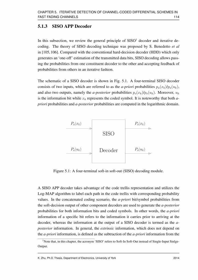
CHAPTER 5. ITERATIVE DETECTION OF CHANNEL-CODED DIFFERENTIAL SCHEMES INFAST FADING CHANNELS 114
5.1.3 SISO APP Decoder
In this subsection, we review the general principle of SISO1 decoder and iterative de-coding. The theory of SISO decoding technique was proposed by S. Benedetto et alin [105, 106]. Compared with the conventional hard-decision decoder (HDD) which onlygenerates an ‘one-off’ estimation of the transmitted data bits, SISO decoding allows pass-ing the probabilities from one constituent decoder to the other and accepting feedback ofprobabilities from others in an iterative fashion.
The schematic of a SISO decoder is shown in Fig. 5.1. A four-terminal SISO decoderconsists of two inputs, which are referred to as the a-priori probabilities pa(xk)/pa(uk),and also two outputs, namely the a-posterior probabilities po(xk)/po(uk). Moreover, ukis the information bit while xk represents the coded symbol. It is noteworthy that both a-priori probabilities and a-posterior probabilities are computed in the logarithmic domain.
SISO
Decoder
Pa(xk)
Pa(uk)
Po(xk)
Po(uk)
Figure 5.1: A four-terminal soft-in soft-out (SISO) decoding module.
A SISO APP decoder takes advantage of the code trellis representation and utilizes theLog-MAP algorithm to label each path in the code trellis with corresponding probabilityvalues. In the concatenated coding scenario, the a-priori bit/symbol probabilities fromthe soft-decision output of other component decoders are used to generate the a-posteriorprobabilities for both information bits and coded symbols. In other words, the a-prioriinformation of a specific bit refers to the information it carries prior to arriving at thedecoder, whereas the information at the output of a SISO decoder is termed as the a-posterior information. In general, the extrinsic information, which does not depend onthe a-priori information, is defined as the subtraction of the a-priori information from the
1Note that, in this chapter, the acronym ‘SISO’ refers to Soft-In Soft-Out instead of Single-Input Sinlge-Output.
K. Zhu, Ph.D. Thesis, Department of Electronics, University of York 2014

CHAPTER 5. ITERATIVE DETECTION OF CHANNEL-CODED DIFFERENTIAL SCHEMES INFAST FADING CHANNELS 115
a-posterior information.
5.2 Low-complexity Iterative Non-coherent Detection ofDifferential Schemes in Fast Fading Channels
Differential phase-shift keying (DPSK), a popular digital modulation scheme debuted sev-eral decades ago [107], has been widely deployed in modern telecommunication, deep-space and satellite applications. DPSK signal carries the information in relative phase (orphase transition) between two adjacent symbols rather than absolute phase, which effec-tively resolves the 2π/M phase ambiguity issue experienced in coherently-detected M -PSK systems. To be more specific, coherent detection of PSK depends on the availabilityof reference phase. Phase ambiguity associated with coherent PSK receiver is caused bythe carrier recovery circuit locking onto a wrong phase instead of the correct referencephase of the carrier [108]. Differential encoding also enables simpler implementationof receivers as carrier synchronization is no longer required. Phase reference could beacquired from the previously-detected symbol due to the unique feature of differentialencoding.
In existing technical literature, the construction of non-coherently detected differentialsystems that are dispensing with channel information, is generally based on the assump-tion that phase rotation is constant or near-constant over several symbol intervals. Typi-cally, this assumption is valid only for very slow fading. The contribution of this chapteris that we consider a more realistic fading channel assumption and we propose the useof a simple differential detector and channel interleaver in conjunction with Turbo codeto improve the reliability of non-coherent decoding and detection under fast fading chan-nels. As a result, several novel differential schemes proposed in this chapter are suitablefor implementation in high mobility applications, such as radio communication betweenbase station and high-speed train.
5.2.1 Historical Review of Differential Schemes under Fast FadingChannels
In general, DPSK systems are optimally detected if multiplicative interferences, such asfading induced by wireless medium, retain constant during observation period. However,
K. Zhu, Ph.D. Thesis, Department of Electronics, University of York 2014
CHAPTER 5. ITERATIVE DETECTION OF CHANNEL-CODED DIFFERENTIAL SCHEMES INFAST FADING CHANNELS 116
a practical differential communication system needs to accommodate the Doppler shiftcaused by the movement of mobile station (MS). Unfortunately, conventional DPSK de-tectors usually fail to recover the information in such scenario, this motivates the questfor novel DPSK detection algorithms that are suitable for high mobility scenarios underfast-faded channels.
The capacity of non-coherent channels is comprehensively studied in [109], informationtheoretic analysis has proved it to be very similar to that of coherent channels. Sincethen, a growing effort has been devoted toward the derivation of improved non-coherentdetection or decoding schemes. In the open technical literature, this problem is addressedin two distinct manners.
Since the error rate of DPSK-modulated systems severely degrades under time-varyingchannel, first solution concentrates on using iteration gain offered from iterative process-ing to compensate the performance loss. For instance, in [110], serial concatenation ofconvolutional and DPSK encoders allows iterative detection and decoding which pro-gressively improves the error performance. To be more specific, a novel soft-decisiondifferential sequential decoder was presented, which exploited the redundancy inherentin the differentially encoded signal. [111] proposed a different non-coherent detection ofDPSK signal using Viterbi algorithm under AWGN channel. Improved version of Viterbialgorithm assisted differential detection was later presented in [112] that was capable ofdealing with frequency-flat Rayleigh fading channel. A more unified and general non-coherent detector was published in [113]. The resulting receiver was optimal in the maxi-mum likelihood detection sense and had demonstrated significant error rate improvementfor a non-selective fading channel with stationary users.
So far, the abovementioned research works at early stage either consider only Gaussiannoise or assume constant fading process. The ground-breaking work devised in [114] de-liveries reliable communication in the presence of Doppler shift by utilizing so-called‘Turbo DPSK’ scheme, which is essentially a serial concatenation of FEC code andDPSK, separated by interleaving. The proposed a-posteriori probability (APP) DPSKsoft demodulator operates following the well-known Bahl-Cocke-Jelinek-Raviv (BCJR)algorithm and is suitable for stationary and time-varying channel. Channel estimator in-corporates linear prediction together with per-survivor processing. This technique henceresults in an exponential expansion of the decoding trellis. Simulations indicate that itis capable of performing asymptotically as well as coded coherent PSK in a Gaussianchannel, while marginally outperforming the corresponding coded coherent PSK in a flatRayleigh fading channel due to time diversity introduced by fading. [115] is anotherlow-complexity solution to detecting Turbo-coded differential PSK signals under corre-
K. Zhu, Ph.D. Thesis, Department of Electronics, University of York 2014

CHAPTER 5. ITERATIVE DETECTION OF CHANNEL-CODED DIFFERENTIAL SCHEMES INFAST FADING CHANNELS 117
lated flat-fading channels. The proposed scheme consists of both forward and backwarddetection processes. By removing the duplicated components in the forward and back-ward processes and assigning a proper combining weight, it is claimed that proposedsub-optimal detector is able to perform as well as, or even outperform, existing scheme athigh signal-to-noise ratio.
On the other hand, non-coherent detection of DPSK signal based on multiple symbolintervals, therefore termed multi-symbol differential detection (MSDD), is also a fa-vored means of data recovery technique when transmitting over fast fading channels.Pioneering work on MSDD can be traced back to late 80’s [57]. Divsalar and Simonpresented their maximum-likelihood non-coherent sequence estimation algorithm aidedMSDD for detecting DPSK signals over AWGN channel, which yielded optimum perfor-mance by employing a block ofN+1 measurements to produceN data decisions. Hence,the deficiency suffered from using DPSK signaling is effectively resolved. Simulationand analytical results indicate multi-symbol differential detector closes the gap betweenconventional (two-symbol interval) non-coherent DPSK detection and ideal coherently-detected PSK with differential encoding (usually designated as DEPSK). MSDD pro-posed by Divsalar and Simon was later extended to trellis coded amplitude modulationand Rayleigh/Rician fading channels [116]. Wilson [117] also presented his independentwork on MSDD. Two heuristic sub-optimal solutions with far less computational com-plexity were also derived, which offered excellent complexity and performance trade-off.Theoretical bit error rate of DBPSK and DQPSK with multi-symbol differential deci-sion under AWGN channel and correlated Rayleigh fading channel were given in [118]and [119], respectively. MSDD was further improved to accommodate soft input as wellas generate soft output, which is ideal for iterative detection of convolutionally-coded,interleaved, DPSK systems.
Furthermore, another sub-optimal but simpler variant of MSDD was proposed in [120].In this new approach, search space for the maximum-likelihood estimation is limited to aspherical region within certain radius, hence termed multiple-symbol differential spheredecoding (MSDSD). Later, the idea of MAP MSDSD was further extended in order toallow iterations with other soft-in soft-out decoder.
It should be pointed out that the performance improvement brought by MSDD and itsreduced-complexity variants, such as MSDSD, is attributed to the extended decision win-dow length. Theoretically, error rate of DPSK system with non-coherent detection couldbe identical to that of coherently-detected DEPSK as observation interval approaches in-finity. It is known that the detection complexity increases exponentially as the windowsize becomes larger. On the contrary, although MSDSD offers an attractive trade-off be-
K. Zhu, Ph.D. Thesis, Department of Electronics, University of York 2014
CHAPTER 5. ITERATIVE DETECTION OF CHANNEL-CODED DIFFERENTIAL SCHEMES INFAST FADING CHANNELS 118
tween performance and complexity, implementation of such algorithm in practice is stillproblematic as it quickly becomes computationally intractable when either the alphabetsize or observation interval grows.
Unique feature of DPSK makes it invariant to phase rotation of multiple of 2π/M , thisimplies channel coefficients could be efficiently estimated with linear prediction in con-junction with per-survivor processing. Linear prediction demonstrates its powerful abilityto track rapid phase variations by taking advantage of the statistical correlation(memory)exhibited by transmission channel. Since the concept of surviving-path is not applica-ble to MAP algorithm, we have to alter the original principle of per-survivor processingby expanding the number of trellis states. The corresponding decoding trellis after expan-sion consists ofMN states withM branches per state. Apparently, the expanded decodingtrellis states increase exponentially with respect to the prediction order. Hence, the com-plexity issue is also endured in the iterative non-coherent DPSK detection scenario. Asthe predictor order becomes larger, increasing number of received samples are involved indecision-making process, hence the performance of coded DPSK scheme is more robustagainst impairments caused by the time-varying nature of the channel. As a result, the de-coding complexity soon becomes prohibitively high. Note that, since channel coefficientsare not explicitly calculated by means of inserting training symbols, it is still reasonableto define the iterative DPSK detection as ‘non-coherent’ scheme.
For those research works from other contributors not mentioned above, we summarizetheir contributions in Tab. 5.1-Tab. 5.4 below in chronological order.
K. Zhu, Ph.D. Thesis, Department of Electronics, University of York 2014

CHAPTER 5. ITERATIVE DETECTION OF CHANNEL-CODED DIFFERENTIAL SCHEMES INFAST FADING CHANNELS 119
Table 5.1: Major contributions of differential technique for fast fading channel (Part I).
Year Author(s) Contribution
1988 Makrakis et al [110] A novel soft-decision sequential decoder, which ex-ploited the redundancy introduced by the differentialencoder, was presented for differentially-coded PSKsignals.
1992 F. Adachi and M. Sawa-hashi [111]
Proposed differential detection of DPSK signal usingViterbi algorithm. The proposed approach was lim-ited to AWGN channel.
1994 Makrakis et al [113] A more unified and improved version was later pub-lished in [113]. The resulting receiver was optimalin the maximum likelihood detection sense and haddemonstrated significant error rate improvement fornon-selective fading channels with stationary users.
1995 G.M. Vitetta and D.P. Tay-lor [112]
Improved version of Viterbi decoding assisted dif-ferential detection that was capable of dealing withfrequency-flat Rayleigh fading channel.
1999 P. Hoeher and J.Lodge [114]
‘Turbo DPSK’ was developed, which was essentiallya serial concatenation of FEC code and DPSK, sepa-rated by interleaving. The proposed APP DPSK de-modulator operates under BCJR algorithm and is suit-able for stationary and time-varying channel. Channelstate estimator incorporates linear prediction togetherwith per-survivor processing. Note that this techniqueresults in an exponential expansion of the decodingtrellis.
K. Zhu, Ph.D. Thesis, Department of Electronics, University of York 2014

CHAPTER 5. ITERATIVE DETECTION OF CHANNEL-CODED DIFFERENTIAL SCHEMES INFAST FADING CHANNELS 120
Table 5.2: Major contributions of differential technique for fast fading channel (Part II).
Year Author(s) Contribution
1999 K.R. Narayanan and G.L.Stuber [121]
This paper investigated iterative demodulation anddecoding of convolutionally-encoded data used withdifferential modulation. It demonstrated that DBPSK,DQPSK, CPM, etc. could be modeled as a recursiverate-1 convolutional code followed by a memorylessmapper. Note that the work presented in this paperwas limited to AWGN channel only.
2000 M. Peleg et al [115] Proposed a serially-concatenated system using half-rate convolutional code with M -DPSK modulation.Channel phase was discretized intoN states, resultingin a linear trellis expansion of MN states.
2000 G. Colavolpe et al [122] Authors in [122] studied non-coherent version ofBCJR algorithm, which follows minimum symbol-error probability criterion under the assumption ofconstant and uniformly distributed phase variations.Note that amplitude fluctuation of transmission chan-nel is not considered in their work.
2006 S.L. Howard and C.Schlegel [123]
Instead of expanding decoding trellis to highly-complicated ‘super-trellis’, proposed APP DPSK de-tector taking advantage of the APP provided by inner(DPSK) soft detector. However, this approach onlyworks when channel phase information is unknownat the receiver, amplitude of the fading process is nottaken into account.
2009 C.C. Lo and S.L. Su [124] Proposed reduced-complexity solution consists ofboth forward and backward detection processes. Byremoving the duplicated component in the forwardand backward processes and assigning a proper com-bining weight, authors claim that proposed sub-optimal scheme is able to perform as well as, or evenoutperform, MSDD at high signal-to-noise.
K. Zhu, Ph.D. Thesis, Department of Electronics, University of York 2014

CHAPTER 5. ITERATIVE DETECTION OF CHANNEL-CODED DIFFERENTIAL SCHEMES INFAST FADING CHANNELS 121
Table 5.3: Major contributions of differential technique for fast fading channel based onMSDD (Part I).
Year Author(s) Contribution
1989 D. Divsalar and M. K. Si-mon [57]
Authors presented the ground-breaking work on non-coherent detection of DPSK signal over AWGN chan-nel. In [57], optimal detection algorithm making useof maximum-likelihood sequence estimation was de-rived and studied. By employing a block of N + 1
measurements to produce N data decisions, the defi-ciency suffered from using DPSK signaling is effec-tively resolved.
1989 S.G. Wilson et al [117] Wilson presented his independent work on MSDDin [117]. Two heuristic sub-optimal solutions with farless computational complexity were proposed, whichoffered great complexity and performance trade-off.
1990 D. Makrakis and K. Fe-her [125]
Makrakis and Feher proposed a similar multiple-symbol interval aided non-coherent sequential re-ceiver that theoretically approached the performanceof coherently-detected DEPSK over static channels.
1994 D. Divsalar and M. K. Si-mon [116]
MSDD proposed by Divsalar and Simon was laterextended to trellis coded amplitude modulation andRayleigh/Rician fading channel.
K. Zhu, Ph.D. Thesis, Department of Electronics, University of York 2014
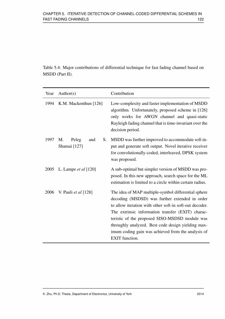
CHAPTER 5. ITERATIVE DETECTION OF CHANNEL-CODED DIFFERENTIAL SCHEMES INFAST FADING CHANNELS 122
Table 5.4: Major contributions of differential technique for fast fading channel based onMSDD (Part II).
Year Author(s) Contribution
1994 K.M. Mackenthun [126] Low-complexity and faster implementation of MSDDalgorithm. Unfortunately, proposed scheme in [126]only works for AWGN channel and quasi-staticRayleigh fading channel that is time-invariant over thedecision period.
1997 M. Peleg and S.Shamai [127]
MSDD was further improved to accommodate soft in-put and generate soft output. Novel iterative receiverfor convolutionally-coded, interleaved, DPSK systemwas proposed.
2005 L. Lampe et al [120] A sub-optimal but simpler version of MSDD was pro-posed. In this new approach, search space for the MLestimation is limited to a circle within certain radius.
2006 V. Pauli et al [128] The idea of MAP multiple-symbol differential spheredecoding (MSDSD) was further extended in orderto allow iteration with other soft-in soft-out decoder.The extrinsic information transfer (EXIT) charac-teristic of the proposed SISO-MSDSD module wasthroughly analyzed. Best code design yielding max-imum coding gain was achieved from the analysis ofEXIT function.
K. Zhu, Ph.D. Thesis, Department of Electronics, University of York 2014

CHAPTER 5. ITERATIVE DETECTION OF CHANNEL-CODED DIFFERENTIAL SCHEMES INFAST FADING CHANNELS 123
5.2.2 Log-MAP Decoding of Uncoded DPSK Signal: A Near-Coherent Performance Approach
In this subsection, we revisit the encoding and decoding procedures for DPSK signal asdiscussed in Section 2.2.2.1. We then introduce the concept of trellis representation of thedifferentially-encoded PSK symbols. The trellis structure of DPSK greatly facilitates theLog-MAP decoding in a non-coherent receiver.
5.2.2.1 Trellis Representation of Differentially-encoded PSK Signal
Information
Source
sk
Mapper
Delay
Differential Encoder
xk−1 xkPSK
Figure 5.2: The transmitter schematic for differentially-encoded PSK modulation.
The schematic of a uncoded DPSK encoding scheme is illustrated in Fig. 5.2. When asequence of information bits arrive at the DPSK encoder, the binary bits are first modu-lated toM-ary complex-valued PSK symbols using a conventional PSK mapper shown inFig. 5.2. It is assumed that the kth PSK-modulated symbol is taken from a finite alphabetS = exp
(2πnjM
), n = 0, 1, 2, ...,M− 1 withM legitimate phasor combinations.
Each transmission period is initialized at epoch 0 with an arbitrary reference symbol s0,the differential encoding process is conducted in a recursive fashion. As depicted inFig. 5.2, the calculation of the DPSK symbol at time k, denoted as xk, is the productof current PSK symbol sk and the previous DPSK symbol xk−1, which is written as
xk =
sk if k = 1,
xk−1 · sk if k > 1.(5.14)
The current DPSK symbol depends on the previous one, differential encoding is repeatedin a similar manner until the end of frame.
Since the DPSK-encoded symbols are taken from a complex-valued set with finite numberof candidates, the dependence between two adjacent DPSK symbols could be modeled by
K. Zhu, Ph.D. Thesis, Department of Electronics, University of York 2014

CHAPTER 5. ITERATIVE DETECTION OF CHANNEL-CODED DIFFERENTIAL SCHEMES INFAST FADING CHANNELS 124
the state transition in an Markov process. The trellis diagrams of the differential BPSKas well as differential QPSK schemes are demonstrated in Fig. 5.3 and Fig. 5.4 respec-tively. Note that the term ‘Codewords’ in Fig. 5.4 indicate the symbol index in the QPSKconstellation set.
s = 1
s = 0
0/1
1/0
1/1
0/0
Figure 5.3: Trellis representation for the differential BPSK scheme.
Codewords States
[ 0 1 2 3 ] S0
[ 1 3 0 2 ] S1
[ 2 0 3 1 ] S2
[ 3 2 1 0 ] S3
Figure 5.4: Trellis representation for the differential QPSK scheme.
According to the trellis diagrams, for aM-ary DPSK signal, there are in totalM trellisstates andM branches per state. Therefore, differential encoder could be viewed from thecoding perspective as the simplest rate-1 recursive non-systematic convolutional encoderwith one memory element. Hence, it is feasible to decode the differential signal withtrellis-based decoding schemes, for example, the Log-MAP algorithm.
After transmission through hostile environment, the DPSK signal received on the other
K. Zhu, Ph.D. Thesis, Department of Electronics, University of York 2014

CHAPTER 5. ITERATIVE DETECTION OF CHANNEL-CODED DIFFERENTIAL SCHEMES INFAST FADING CHANNELS 125
end of the communication link yk is defined by
yk = hkxk + nk , (5.15)
where hk is the Rayleigh fading coefficient at time interval k and nk represents the Gaus-sian noise. The well-known Jake’s land-mobile model is used to characterize and reflectthe time-variant nature of the fading process hk. This channel model implies that bothamplitude as well as phase of the signal are distorted when transmitting through the fad-ing channel. The corresponding normalized auto-correlation function R(l) is expressedas [29]
R(l) = J0(2πfmaxTsl) . (5.16)
At epoch k, the conditional probability of receiving yk, conditioned on the transmittedDPSK symbol xk and correlated Rayleigh fading channel coefficient hk, is determined bythe PDF of the noise, which gives
pyk|hk,xk ∝ exp− 1
N0
||yk − hkxk)||2, (5.17)
After obtaining the channel metric, the Log-MAP decoding is carried out to estimatePSK-modulated symbol sk in the usual way as in a coherent system with the a-posterioriLLR vector of the data bits set to zeros.
5.2.2.2 APP DPSK Decoder
It can be seen from Eq. (5.17), accurate calculation of the channel metric relies on theavailability of channel information. Acquisition of channel estimate is difficult at thereceiver when the channel is rapidly changing or the system is operating at low SNR.Furthermore, low complexity is one of the most important design considerations in thiswork. Hence, in order to keep the selected channel estimator as simple as possible, neitherthe training-based approach nor optimal linear estimator, for example, minimum mean-square error (MMSE) estimator is employed.
Moreover, the symmetrical property of the DPSK trellis results in the DPSK trellis de-coder is invariant to phase rotations as confirmed in [123]. This unique feature signifi-cantly simplifies the requirement on the channel estimation accuracy as the decoding isstill correct even if the phase of the estimated channel coefficient is slipped by multiplesof 2π/M. As a remedy, the estimated channel coefficient at epoch k + 1, denoted ashk+1, is calculated with the a-posteriori probability of the kth symbol at the output of
K. Zhu, Ph.D. Thesis, Department of Electronics, University of York 2014

CHAPTER 5. ITERATIVE DETECTION OF CHANNEL-CODED DIFFERENTIAL SCHEMES INFAST FADING CHANNELS 126
DPSK Log-MAP decoder. hk+1 is then incorporated in the computation of a-posterioriprobability for the (k+ 1)th received symbol. A up-to-date channel estimate is generatedwith the latest a-posteriori symbol probabilities. This approach is therefore termed APPnon-coherent decoding.
A more formal description of the APP non-coherent decoding procedure is detailed in therest part of this subsection. At the beginning of transmission, the channel coefficients arecompletely unknown. Hence, an initial assumption of hk = 1 is proposed. If we denotethe output a posteriori probability for the kth received symbol as po(xk), the expectationover po(xk) defines the estimated soft symbol or expected symbol xk.
xk = E[xk] =M−1∑
i=0
exp
(j2πi
M
)po
(xk = exp
(j2πi
M
)). (5.18)
In the following steps, the instantaneous channel estimate is calculated as
hk = ykx∗k , (5.19)
where (·)∗ is the complex conjugate.
In the case of static channels or slowly-faded channels, the final channel estimate is simplythe average of the instantaneous channel estimates, which gives
hk =
∑Nk=1 hkN
. (5.20)
For fast fading channels, the instantaneous channel estimate is passed through a smootherwith forgetting factor α, the smoothed final channel estimate is invoked to decode thetransmitted symbol at next time slot. The definition of the smoother is expressed as
hk =
∑Nfi=−Np α
(Nw−i)hk(k + i)
Nw
, (5.21)
where α is the forgetting factor, a small number between 0 and 1. Np and Nf are thenumber of past symbols and the number of future symbols, while Nw = Np + Nf + 1 isthe total number of samples used in each smoothing operation.
5.2.2.3 Decision Feedback Differential Detection (DFDD) aided DPSK Decoder
Recall the transmission model used in Eq. (5.15) is under the assumption of correlatedRayleigh fading following classical Jake’s model. We could define the estimated channelcoefficient as a noisy version of the original one, that is
hk = hk + ek . (5.22)
K. Zhu, Ph.D. Thesis, Department of Electronics, University of York 2014
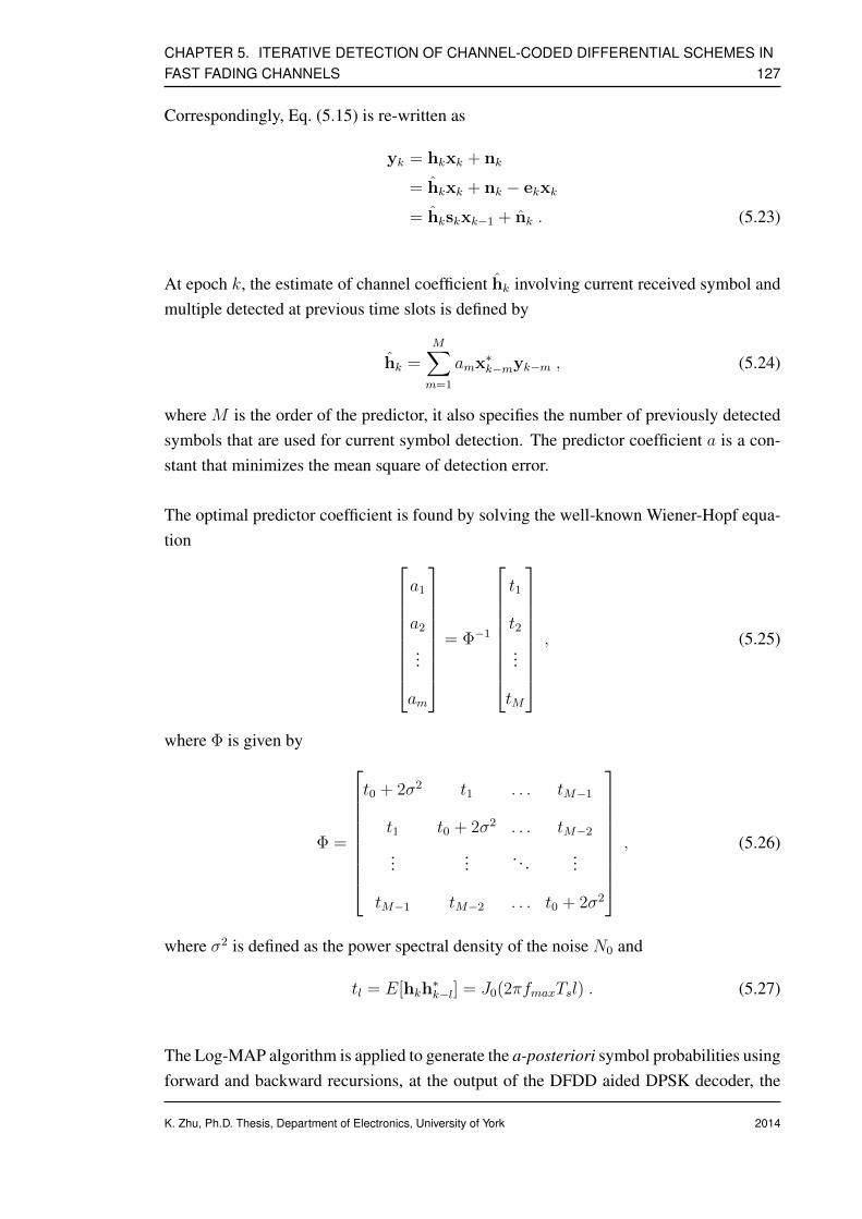
CHAPTER 5. ITERATIVE DETECTION OF CHANNEL-CODED DIFFERENTIAL SCHEMES INFAST FADING CHANNELS 127
Correspondingly, Eq. (5.15) is re-written as
yk = hkxk + nk
= hkxk + nk − ekxk
= hkskxk−1 + nk . (5.23)
At epoch k, the estimate of channel coefficient hk involving current received symbol andmultiple detected at previous time slots is defined by
hk =M∑
m=1
amx∗k−myk−m , (5.24)
where M is the order of the predictor, it also specifies the number of previously detectedsymbols that are used for current symbol detection. The predictor coefficient a is a con-stant that minimizes the mean square of detection error.
The optimal predictor coefficient is found by solving the well-known Wiener-Hopf equa-tion
a1
a2
...
am
= Φ−1
t1
t2
...
tM
, (5.25)
where Φ is given by
Φ =
t0 + 2σ2 t1 . . . tM−1
t1 t0 + 2σ2 . . . tM−2
...... . . . ...
tM−1 tM−2 . . . t0 + 2σ2
, (5.26)
where σ2 is defined as the power spectral density of the noise N0 and
tl = E[hkh∗k−l] = J0(2πfmaxTsl) . (5.27)
The Log-MAP algorithm is applied to generate the a-posteriori symbol probabilities usingforward and backward recursions, at the output of the DFDD aided DPSK decoder, the
K. Zhu, Ph.D. Thesis, Department of Electronics, University of York 2014

CHAPTER 5. ITERATIVE DETECTION OF CHANNEL-CODED DIFFERENTIAL SCHEMES INFAST FADING CHANNELS 128
a-posteriori symbol probabilities are formulated by
p (xk = xk(n)) =∑(
p(yk|xk,hk)all m∏
m6=n
p(xk(m)))
n = 0, 1, 2, ...,M− 1 ,
(5.28)
where xk(n) implies the nth symbol in the DPSK constellation set assigned to the kthsymbol in the transmitted DPSK sequence. Moreover, the conditional probability ofp(yk|xk,hk) indicates the probability of receiving yk, given that the transmitted DPSKsymbol is xk as well as the Rayleigh fading channel hk, which is determined by the PDFof the noise, it gives
p(yk|xk,hk) =1
πN0
exp(− ||yk − hkxk||2
N0
), (5.29)
Substituting Eq. (5.24) into Eq. (5.29), the resultant channel metric for the Log-MAPdecoding of DPSK symbols is defined as
pyk|hk, sk,xk−1 ∝ exp− 1
N0
||yk − sk(hkxk−1)||2, (5.30)
Further substituting Eq. (5.24), Eq. (5.25), Eq. (5.26) and Eq. (5.27) into Eq. (5.30), aftersome manipulation and simplification, it yields the non-coherent detection metric that isindependent of the channel coefficients, giving
exp
1
N0
< M∑
m=1
amy∗ksk
(m−1∏
j=1
sk−j
)yk−m
. (5.31)
The interpretation of Eq. (5.31) is two-fold. For minimizing the decoding error rateand achieving the best decoding performance, all legitimate PSK-modulated symbolssk, sk−1, ..., sk−m+1 are exhaustively searched and examined for the recovery of sk+1
leading to a sophisticated decoding structure. On the other hand, as a simpler alternative,the previously-detected symbols sk−1, sk−2, ..., sk−m+1 are substituted into Eq. (5.31)to compute sk+1 at time instant k + 1.
5.2.2.4 Performance Results and Observations
In this subsection, we evaluate the error performance of the differentially-encoded PSKusing Log-MAP algorithm when communicating over AWGN channel and correlatedRayleigh fading channel with normalized Doppler frequency fdop = 0.002. We assume
K. Zhu, Ph.D. Thesis, Department of Electronics, University of York 2014
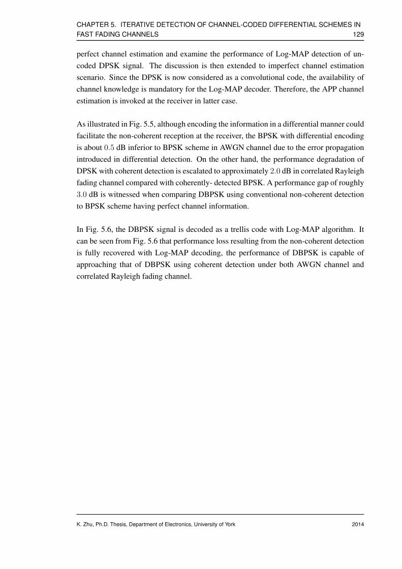
CHAPTER 5. ITERATIVE DETECTION OF CHANNEL-CODED DIFFERENTIAL SCHEMES INFAST FADING CHANNELS 129
perfect channel estimation and examine the performance of Log-MAP detection of un-coded DPSK signal. The discussion is then extended to imperfect channel estimationscenario. Since the DPSK is now considered as a convolutional code, the availability ofchannel knowledge is mandatory for the Log-MAP decoder. Therefore, the APP channelestimation is invoked at the receiver in latter case.
As illustrated in Fig. 5.5, although encoding the information in a differential manner couldfacilitate the non-coherent reception at the receiver, the BPSK with differential encodingis about 0.5 dB inferior to BPSK scheme in AWGN channel due to the error propagationintroduced in differential detection. On the other hand, the performance degradation ofDPSK with coherent detection is escalated to approximately 2.0 dB in correlated Rayleighfading channel compared with coherently- detected BPSK. A performance gap of roughly3.0 dB is witnessed when comparing DBPSK using conventional non-coherent detectionto BPSK scheme having perfect channel information.
In Fig. 5.6, the DBPSK signal is decoded as a trellis code with Log-MAP algorithm. Itcan be seen from Fig. 5.6 that performance loss resulting from the non-coherent detectionis fully recovered with Log-MAP decoding, the performance of DBPSK is capable ofapproaching that of DBPSK using coherent detection under both AWGN channel andcorrelated Rayleigh fading channel.
K. Zhu, Ph.D. Thesis, Department of Electronics, University of York 2014
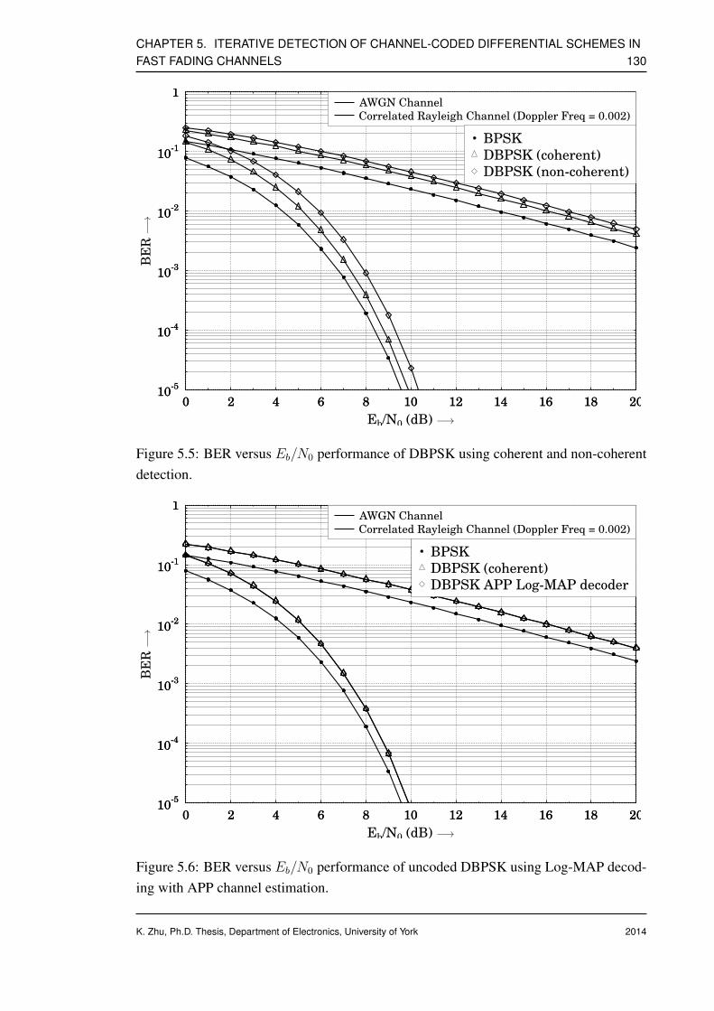
CHAPTER 5. ITERATIVE DETECTION OF CHANNEL-CODED DIFFERENTIAL SCHEMES INFAST FADING CHANNELS 130
10-5
10-4
10-3
10-2
10-1
1
0 2 4 6 8 10 12 14 16 18 2010
-5
10-4
10-3
10-2
10-1
1
BER
0 2 4 6 8 10 12 14 16 18 20
Eb/N0 (dB)
AWGN Channel
Correlated Rayleigh Channel (Doppler Freq = 0.002)
BPSK
DBPSK (coherent)
DBPSK (non-coherent)
−→
−→
Figure 5.5: BER versus Eb/N0 performance of DBPSK using coherent and non-coherentdetection.
10-5
10-4
10-3
10-2
10-1
1
0 2 4 6 8 10 12 14 16 18 2010
-5
10-4
10-3
10-2
10-1
1
BER
0 2 4 6 8 10 12 14 16 18 20
Eb/N0 (dB)
AWGN Channel
Correlated Rayleigh Channel (Doppler Freq = 0.002)
BPSK
DBPSK (coherent)
DBPSK APP Log-MAP decoder
−→
−→
Figure 5.6: BER versus Eb/N0 performance of uncoded DBPSK using Log-MAP decod-ing with APP channel estimation.
K. Zhu, Ph.D. Thesis, Department of Electronics, University of York 2014
CHAPTER 5. ITERATIVE DETECTION OF CHANNEL-CODED DIFFERENTIAL SCHEMES INFAST FADING CHANNELS 131
5.2.3 Turbo Principle aided Detection and Decoding of Channel-coded Differential PSK
5.2.3.1 System Model
Consider a serially-concatenated coding system with differential PSK modulation as il-lustrated in Fig. 5.7, which consists of a convolutional or Turbo encoder, a differentialencoder and a PSK mapper. In order to provide additional protection against fading aswell as eliminate the correlation of adjacent coded bits, a bit interleaver π is placed be-tween two component codes to re-order the transmission of the symbols.
Encoderπ PSK Mapper
FEC
a[k]D
b[k] c[k] s[k] x[k]
Diff. PSK Encoder
Figure 5.7: The schematic of a FEC-coded differential PSK transmitter.
The input to the FEC encoder is independent and equipropable i-bit information wordsak = a[1], a[2], .., a[k]. The output of the encoder is n-bit coded words bk =
b[1],b[2], ..,b[k]. The code rate is therefore defined as i/n. The resultant convolu-tional or Turbo codewords are subsequently permuted and modulated to complex-valuedPSK symbols sk with various signal labeling, which are further encoded by outer rate-1convolutional encoder, i.e. differential encoder. At epoch k, the differentially-modulatedFEC-coded symbols are generated recursively as
x[k] =
s[k] if k = 1,
x[k − 1] · s[k] if k > 1.(5.32)
The radio signal is distorted and contaminated by rapidly time-variant fading incurredduring transmission, along with Gaussian noise imposed at the receiver. Transmissionchannel is modeled as frequency non-selective band-limited correlated Rayleigh fadingdefined by Jake’s model. Note that, as there is no universally accepted definition of fastfading, we consider the communication channel is fast-faded when normalized Dopplerfrequency is greater than 0.05.
K. Zhu, Ph.D. Thesis, Department of Electronics, University of York 2014

CHAPTER 5. ITERATIVE DETECTION OF CHANNEL-CODED DIFFERENTIAL SCHEMES INFAST FADING CHANNELS 132
The corresponding received signal at the matched filter output at time instant k can bewritten as
y[k] = h[k]x[k] + n[k] , (5.33)
where hk is the complex-valued correlated Rayleigh fading coefficients, while nk denotesthe AWGN induced at the receiver having zero mean and variance ofN0/2 per dimension.Received signal is differentially detected with non-coherent approach as well as semi non-coherent methods based on the estimated channel, including APP channel estimation andDFDD aided channel estimation in following two subsections.
5.2.3.2 Non-coherent DPSK Demapper
y[k]
e(b[k])a(c[k])
e(c[k]) a(b[k])
a[k]
DPSK Soft Demapper
PSKSoft
Demapper
D
π
π−1 RSC
Decoder
Figure 5.8: The proposed receiver structure for jointly detecting and decoding the serialconcatenation of RSC and DPSK modulation.
The received samples are differentially detected by multiplying each sample by the com-plex conjugate of the previous one, recall that the kth received symbol is expressed as
y[k] = h[k]x[k] + n[k] , (5.34)
The previous received sample at epoch k − 1 is given in a similar way
y[k − 1] = h[k − 1]x[k − 1] + n[k − 1] , (5.35)
Subsequently, the product of Eq. (5.34) and Eq. (5.35) is used to define the equivalentversion of the received signal when the channel states at epoch k − 1 and k are identical,namely hk = hk−1, which gives
y[k] = y[k]y∗[k − 1]
=(h[k]x[k] + n[k]
)(h∗[k − 1]x∗[k − 1] + n∗[k − 1]
)
=∣∣y[k − 1]
∣∣2︸ ︷︷ ︸
h[k]
s[k] + n[k] , (5.36)
K. Zhu, Ph.D. Thesis, Department of Electronics, University of York 2014

CHAPTER 5. ITERATIVE DETECTION OF CHANNEL-CODED DIFFERENTIAL SCHEMES INFAST FADING CHANNELS 133
Note that Eq. (5.36) is the re-constructed version of y[k], it can be re-arranged as
y[k] = h[k]s[k] + n[k] , (5.37)
in Eq. (5.37), transmitted symbols are now PSK-modulated symbols prior to differen-tial encoding s[k], and n[k] is the new noise term that its variance is doubled to reflectthe additional noise introduced during the differential detection. Moreover, h[k] can beinterpreted as the new channel vector.
Calculations in Eq. (5.36) transform the differential transmission model to the absolutely-modulated PSK model. The a-posteriori symbol probabilities are generated with PSKLog-MAP demapping utilizing Eq. (5.17) as described in Section 5.2.2.1 and in [129].
5.2.3.3 Semi Non-coherent Approaches Using Estimated Channel
Iterative Non-coherent APP Receiver
y[k]
e(b[k])a(s[k])
e(s[k]) a(b[k])a[k]
DPSK Soft Demapper
PSKSoft
Demapper π
π−1 RSC
Decoder
Diff.
Decoder
e(c[k])
a(c[k])
Figure 5.9: The schematic of the proposed iterative non-coherent APP receiver archi-tecture for jointly detecting and decoding the serial concatenation of channel code andDPSK.
As described in Section 5.2.2.1, the differential PSK can be considered as a unity-raterecursive non-systematic convolutional code followed by a conventional memoryless PSKmapper due to the recursive nature of the DPSK encoding. The schematic of a channel-coded DPSK transmitter portrayed in Fig. 5.7 is an analogy to the serially concatenatedcoding (SCC) scheme.
It is well-known that SCC schemes are capable of achieving infinitesimally low prob-ability of error by using several conventional binary error-correction codes as compo-nent codes and decoding the information bits iteratively at the receiver. In channel-codedDPSK scenario, the PSK soft demapper and the FEC decoder serve as the inner and outer
K. Zhu, Ph.D. Thesis, Department of Electronics, University of York 2014
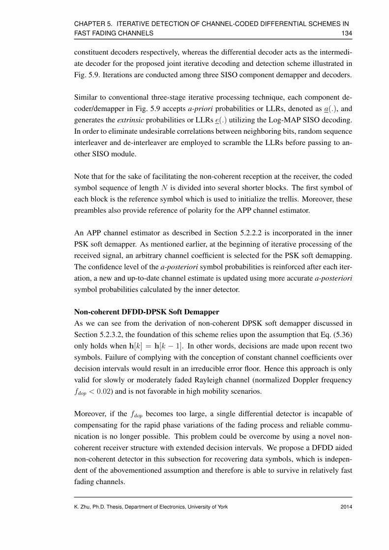
CHAPTER 5. ITERATIVE DETECTION OF CHANNEL-CODED DIFFERENTIAL SCHEMES INFAST FADING CHANNELS 134
constituent decoders respectively, whereas the differential decoder acts as the intermedi-ate decoder for the proposed joint iterative decoding and detection scheme illustrated inFig. 5.9. Iterations are conducted among three SISO component demapper and decoders.
Similar to conventional three-stage iterative processing technique, each component de-coder/demapper in Fig. 5.9 accepts a-priori probabilities or LLRs, denoted as a(.), andgenerates the extrinsic probabilities or LLRs e(.) utilizing the Log-MAP SISO decoding.In order to eliminate undesirable correlations between neighboring bits, random sequenceinterleaver and de-interleaver are employed to scramble the LLRs before passing to an-other SISO module.
Note that for the sake of facilitating the non-coherent reception at the receiver, the codedsymbol sequence of length N is divided into several shorter blocks. The first symbol ofeach block is the reference symbol which is used to initialize the trellis. Moreover, thesepreambles also provide reference of polarity for the APP channel estimator.
An APP channel estimator as described in Section 5.2.2.2 is incorporated in the innerPSK soft demapper. As mentioned earlier, at the beginning of iterative processing of thereceived signal, an arbitrary channel coefficient is selected for the PSK soft demapping.The confidence level of the a-posteriori symbol probabilities is reinforced after each iter-ation, a new and up-to-date channel estimate is updated using more accurate a-posteriorisymbol probabilities calculated by the inner detector.
Non-coherent DFDD-DPSK Soft DemapperAs we can see from the derivation of non-coherent DPSK soft demapper discussed inSection 5.2.3.2, the foundation of this scheme relies upon the assumption that Eq. (5.36)only holds when h[k] = h[k − 1]. In other words, decisions are made upon recent twosymbols. Failure of complying with the conception of constant channel coefficients overdecision intervals would result in an irreducible error floor. Hence this approach is onlyvalid for slowly or moderately faded Rayleigh channel (normalized Doppler frequencyfdop < 0.02) and is not favorable in high mobility scenarios.
Moreover, if the fdop becomes too large, a single differential detector is incapable ofcompensating for the rapid phase variations of the fading process and reliable commu-nication is no longer possible. This problem could be overcome by using a novel non-coherent receiver structure with extended decision intervals. We propose a DFDD aidednon-coherent detector in this subsection for recovering data symbols, which is indepen-dent of the abovementioned assumption and therefore is able to survive in relatively fastfading channels.
K. Zhu, Ph.D. Thesis, Department of Electronics, University of York 2014

CHAPTER 5. ITERATIVE DETECTION OF CHANNEL-CODED DIFFERENTIAL SCHEMES INFAST FADING CHANNELS 135
e(b[k])a(c[k])
e(c[k]) a(b[k])a[k]
π
π−1 FEC
Decoder
y[k]DFDD-aided
Soft DPSK
Demapper
Figure 5.10: Receiver structure for non-coherent DFDD-DPSK soft demapper.
Fig. 5.10 illustrates the structure of the iterative non-coherent soft demapper with embed-ded DFDD channel estimator in a FEC-coded and interleaved system. The notations a(·)and e(·) represent the sequences containing the a-priori LLRs and extrinsic LLRs respec-tively. In the proposed iterative non-coherent scheme, splitting the data frame into severalsegments with shorter length is no longer required.
The DFDD aided non-coherent detection is initialized by transmission of np number ofpreambles, the length of which equals to the order of the channel estimator M . With theassistance of M previously-detected data symbols, the a-posteriori symbol probabilitiescan be computed efficiently with DFDD algorithm and Eq. (5.31). The complexity ofDFDD channel estimator is linearly proportional to the DPSK constellation size.
DFDD aided Iterative Non-coherent Receiver
The schematic of the proposed DFDD aided three-stage non-coherent iterative detectionand decoding scheme is shown in Fig. 5.11.
a(s[k])
e(s[k]) a[k]
h[k]
PSKSoft
Demapper
Diff.
Decoder
TrellisFEC
Decoder
y[k]
Channel Estimator
DFDD
aided
e(b[k])
a(b[k])
π
π−1e(c[k])
a(c[k])
Figure 5.11: The schematic of the proposed DFDD aided iterative non-coherent jointdetection and decoding scheme.
The receiver structure as well as decoding principle are very similar to those employed inthe iterative non-coherent APP receiver; however the APP channel estimator is replacedwith the DFDD channel estimator, the performance of which is more robust in fast fading
K. Zhu, Ph.D. Thesis, Department of Electronics, University of York 2014
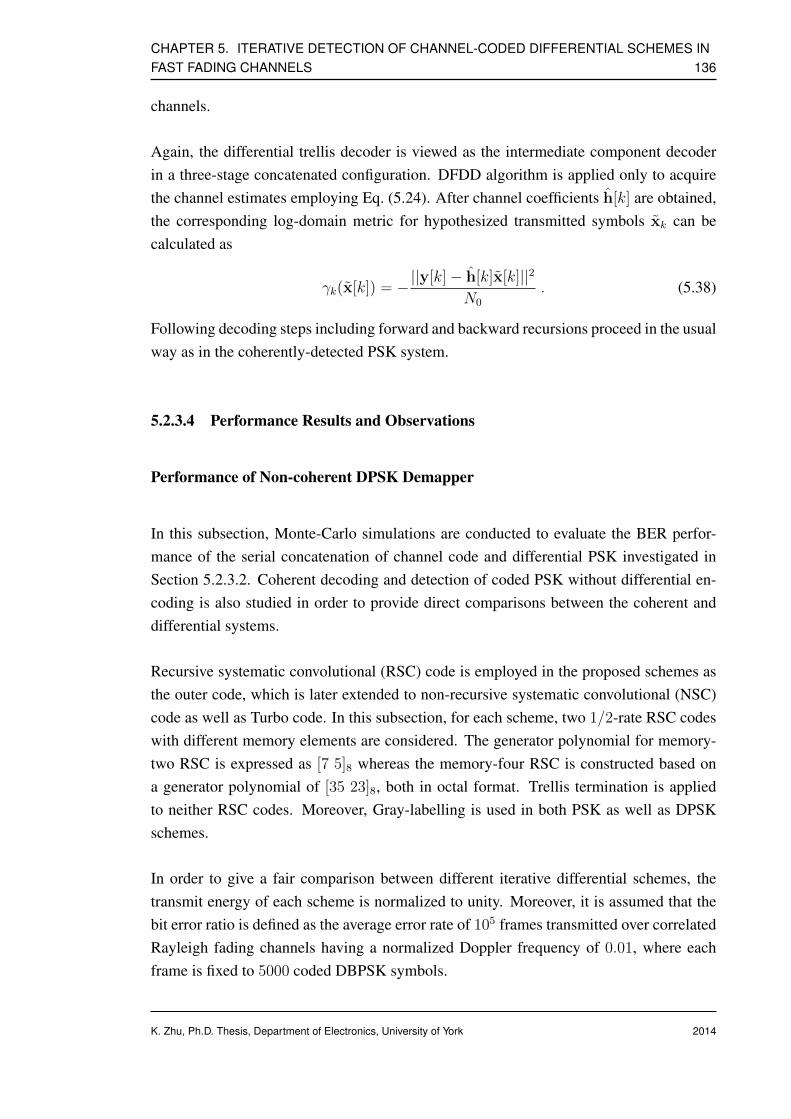
CHAPTER 5. ITERATIVE DETECTION OF CHANNEL-CODED DIFFERENTIAL SCHEMES INFAST FADING CHANNELS 136
channels.
Again, the differential trellis decoder is viewed as the intermediate component decoderin a three-stage concatenated configuration. DFDD algorithm is applied only to acquirethe channel estimates employing Eq. (5.24). After channel coefficients h[k] are obtained,the corresponding log-domain metric for hypothesized transmitted symbols xk can becalculated as
γk(x[k]) = −||y[k]− h[k]x[k]||2N0
. (5.38)
Following decoding steps including forward and backward recursions proceed in the usualway as in the coherently-detected PSK system.
5.2.3.4 Performance Results and Observations
Performance of Non-coherent DPSK Demapper
In this subsection, Monte-Carlo simulations are conducted to evaluate the BER perfor-mance of the serial concatenation of channel code and differential PSK investigated inSection 5.2.3.2. Coherent decoding and detection of coded PSK without differential en-coding is also studied in order to provide direct comparisons between the coherent anddifferential systems.
Recursive systematic convolutional (RSC) code is employed in the proposed schemes asthe outer code, which is later extended to non-recursive systematic convolutional (NSC)code as well as Turbo code. In this subsection, for each scheme, two 1/2-rate RSC codeswith different memory elements are considered. The generator polynomial for memory-two RSC is expressed as [7 5]8 whereas the memory-four RSC is constructed based ona generator polynomial of [35 23]8, both in octal format. Trellis termination is appliedto neither RSC codes. Moreover, Gray-labelling is used in both PSK as well as DPSKschemes.
In order to give a fair comparison between different iterative differential schemes, thetransmit energy of each scheme is normalized to unity. Moreover, it is assumed that thebit error ratio is defined as the average error rate of 105 frames transmitted over correlatedRayleigh fading channels having a normalized Doppler frequency of 0.01, where eachframe is fixed to 5000 coded DBPSK symbols.
K. Zhu, Ph.D. Thesis, Department of Electronics, University of York 2014

CHAPTER 5. ITERATIVE DETECTION OF CHANNEL-CODED DIFFERENTIAL SCHEMES INFAST FADING CHANNELS 137
10-5
10-4
10-3
10-2
10-1
1
0 2 4 6 8 10 12 14 16 18 2010
-5
10-4
10-3
10-2
10-1
1
BER
0 2 4 6 8 10 12 14 16 18 20
Eb/N0 (dB)
Proposed iterative non-coherent demapper
Coherent decoding of RSC-PSK
RSC [7 5]8RSC [35 23]8
Overall throughput = 0.5 bps
−→
−→
Figure 5.12: BER versusEb/N0 performance of the proposed novel iterative non-coherentDPSK demapper for RSC coded DPSK system when communicating over correlatedRayleigh fading channel, where 4 iterations are used between the soft DPSK demapperand RSC decoder.
K. Zhu, Ph.D. Thesis, Department of Electronics, University of York 2014

CHAPTER 5. ITERATIVE DETECTION OF CHANNEL-CODED DIFFERENTIAL SCHEMES INFAST FADING CHANNELS 138
In Fig. 5.12, the BER performance of non-coherent DPSK demapper is depicted and com-pared with its coherent counterpart. Four iterations are assumed between the soft DPSKdemapper and RSC decoder. As shown in Fig. 5.12, approximately 3.0 dB performanceloss is witnessed between the RSC-PSK and RSC-DPSK schemes. Similar observation isalso found in conventional non-coherent demodulation schemes without employing anyouter code, which implies that the improvement contributed from such receiver structureis very limited as the DPSK demapper is unable to exploit the time diversity introducedby the channel code.
Performance of Iterative Non-coherent APP Receiver
Significant performance improvement is achieved by exploiting the recursive nature inher-ent in the differential codes. The proposed iterative APP DPSK decoder applies Log-MAPtrellis decoding and iterates four times with outer RSC decoder. Discussions commencefrom a simple scenario assuming perfect channel estimation, the BER versus Eb/N0 per-formance of the proposed scheme using memory-two RSC as well as memory-four RSCare illustrated in Fig. 5.13 and Fig. 5.14 respectively. As shown in Fig. 5.13, the slopeof curves corresponding to the proposed iterative non-coherent decoder are much steeperdue to the time diversity. The performance degradation experienced in the previous sys-tem is narrowed down to 2.0 dB after the first iteration, whereas the RSC-DPSK schemeeven outperforms the corresponding RSC-PSK by 3.0 dB at BER= 10−4 as the number ofiterations is increased to two. Further iteration gain of more than 5.0 dB is achieved afterfour iterations. Similar trend is observed in Fig. 5.14, in which a more sophisticated RSCcode with a generator polynomial of [35 23]8 is employed. At BER= 10−4, the proposedRSC-DPSK scheme is about 3.5 dB superior to the coherent RSC-PSK after only fouriterations.
Next, the impact of imperfect channel estimation is taken into consideration. The resultsshown in Fig. 5.15 are based on the estimated channel coefficients provided by the APPchannel estimator. If APP channel estimator is designed with following parameters: for-getting factor α = 0.99, Nw = 30, Np = 12, Nf = 17 and block length is 11% of theframe length, imperfect channel coefficients only incur 1.0 dB performance degradation atBER= 10−4. For the case of employing memory-four RSC with stronger error-correctioncapabilities, a slight performance loss of approximately 0.5 dB is expected.
K. Zhu, Ph.D. Thesis, Department of Electronics, University of York 2014

CHAPTER 5. ITERATIVE DETECTION OF CHANNEL-CODED DIFFERENTIAL SCHEMES INFAST FADING CHANNELS 139
10-5
10-4
10-3
10-2
10-1
1
0 2 4 6 8 10 12 14 16 18 2010
-5
10-4
10-3
10-2
10-1
1
BER
0 2 4 6 8 10 12 14 16 18 20
Eb/N0 (dB)
Proposed iterative non-coherent trellis decoder
Coherent decoding of RSC-PSK
1 iteration
2 iteration
4 iteration
Overall throughput = 0.5 bps
−→
−→
Figure 5.13: BER versusEb/N0 performance of the proposed novel iterative non-coherentDPSK trellis decoder for RSC coded DPSK system. Generator polynomial of the RSCencoder is [7 5]8 and 4 iterations are used between the DPSK trellis decoder and RSCdecoder.
K. Zhu, Ph.D. Thesis, Department of Electronics, University of York 2014

CHAPTER 5. ITERATIVE DETECTION OF CHANNEL-CODED DIFFERENTIAL SCHEMES INFAST FADING CHANNELS 140
10-5
10-4
10-3
10-2
10-1
1
0 2 4 6 8 10 12 14 16 18 2010
-5
10-4
10-3
10-2
10-1
1
BER
0 2 4 6 8 10 12 14 16 18 20
Eb/N0 (dB)
Proposed iterative non-coherent trellis decoder
Coherent decoding of RSC-PSK
1 iteration
2 iteration
4 iteration
Overall throughput = 0.5 bps
−→
−→
Figure 5.14: BER versusEb/N0 performance of the proposed novel iterative non-coherentDPSK trellis decoder for RSC coded DPSK system. Generator polynomial of the RSCencoder is [35 23]8 and 4 iterations are used between the DPSK trellis decoder and RSCdecoder.
K. Zhu, Ph.D. Thesis, Department of Electronics, University of York 2014

CHAPTER 5. ITERATIVE DETECTION OF CHANNEL-CODED DIFFERENTIAL SCHEMES INFAST FADING CHANNELS 141
10-5
10-4
10-3
10-2
10-1
1
0 1 2 3 4 5 6 7 8 9 1010
-5
10-4
10-3
10-2
10-1
1
BER
0 1 2 3 4 5 6 7 8 9 10
Eb/N0 (dB)
Iterative non-coherent trellis decoder with estimated channel (4 iteration)
Iterative non-coherent trellis decoder with perfect CSI (4 iteration)
RSC [7 5]8RSC [35 23]8
Overall throughput = 0.5 bps
−→
−→
Figure 5.15: Comparison of BER versus Eb/N0 performance of the proposed novel iter-ative DPSK trellis decoder with perfect and imperfect CSI. 4 iterations are used betweenthe DPSK trellis decoder and RSC decoder.
K. Zhu, Ph.D. Thesis, Department of Electronics, University of York 2014
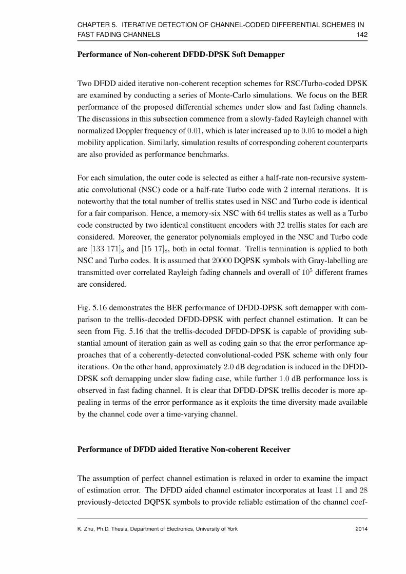
CHAPTER 5. ITERATIVE DETECTION OF CHANNEL-CODED DIFFERENTIAL SCHEMES INFAST FADING CHANNELS 142
Performance of Non-coherent DFDD-DPSK Soft Demapper
Two DFDD aided iterative non-coherent reception schemes for RSC/Turbo-coded DPSKare examined by conducting a series of Monte-Carlo simulations. We focus on the BERperformance of the proposed differential schemes under slow and fast fading channels.The discussions in this subsection commence from a slowly-faded Rayleigh channel withnormalized Doppler frequency of 0.01, which is later increased up to 0.05 to model a highmobility application. Similarly, simulation results of corresponding coherent counterpartsare also provided as performance benchmarks.
For each simulation, the outer code is selected as either a half-rate non-recursive system-atic convolutional (NSC) code or a half-rate Turbo code with 2 internal iterations. It isnoteworthy that the total number of trellis states used in NSC and Turbo code is identicalfor a fair comparison. Hence, a memory-six NSC with 64 trellis states as well as a Turbocode constructed by two identical constituent encoders with 32 trellis states for each areconsidered. Moreover, the generator polynomials employed in the NSC and Turbo codeare [133 171]8 and [15 17]8, both in octal format. Trellis termination is applied to bothNSC and Turbo codes. It is assumed that 20000 DQPSK symbols with Gray-labelling aretransmitted over correlated Rayleigh fading channels and overall of 105 different framesare considered.
Fig. 5.16 demonstrates the BER performance of DFDD-DPSK soft demapper with com-parison to the trellis-decoded DFDD-DPSK with perfect channel estimation. It can beseen from Fig. 5.16 that the trellis-decoded DFDD-DPSK is capable of providing sub-stantial amount of iteration gain as well as coding gain so that the error performance ap-proaches that of a coherently-detected convolutional-coded PSK scheme with only fouriterations. On the other hand, approximately 2.0 dB degradation is induced in the DFDD-DPSK soft demapping under slow fading case, while further 1.0 dB performance loss isobserved in fast fading channel. It is clear that DFDD-DPSK trellis decoder is more ap-pealing in terms of the error performance as it exploits the time diversity made availableby the channel code over a time-varying channel.
Performance of DFDD aided Iterative Non-coherent Receiver
The assumption of perfect channel estimation is relaxed in order to examine the impactof estimation error. The DFDD aided channel estimator incorporates at least 11 and 28
previously-detected DQPSK symbols to provide reliable estimation of the channel coef-
K. Zhu, Ph.D. Thesis, Department of Electronics, University of York 2014

CHAPTER 5. ITERATIVE DETECTION OF CHANNEL-CODED DIFFERENTIAL SCHEMES INFAST FADING CHANNELS 143
ficients under slow and fast fading scenarios respectively. Note that the same number ofreference symbols are required at the beginning of each frame to initialize the process;however compared with the relatively large frame length, these preambles are negligible.
As we can see from Fig. 5.17, the proposed DFDD-DPSK trellis decoder with block in-terleaver is about 1.0−1.5 dB inferior to its counterpart with perfect channel information.As a remedy, in Fig. 5.18, a sequence interleaver is employed to partly compensate theperformance degradation. A direct comparison of Fig. 5.18 to Fig. 6 of [114] confirmsthat our proposed DFDD-DPSK trellis decoder is capable of performing as well as thelinear prediction based scheme in [114], the computational complexity of which is higherthan ours by several orders of magnitude.
Our concentration is shifted to fast fading scenario shown in Fig. 5.19, a further per-formance loss of roughly 2.8 dB is witnessed if compared with the slow fading case atBER= 10−4. Therefore, the BER results of the proposed scheme are only 1.0 dB worsethan those reported in [114], which is acceptable as it is achieved by a much simplerdecoding structure.
In the rest part of this subsection, Turbo code is employed to further narrow down theperformance gap caused by imperfect channel estimation. It can be seen from Fig. 5.20,the proposed scheme benefits from substantial amount of improvement in slowly-fadedchannel and even more performance gain is acquired under fast fading channel due totime diversity provided by the time-varying channel. As expected, at BER= 10−4, theTurbo-coded DQPSK scheme outperforms the corresponding NSC-coded systems by 1.0
dB and 2.2 dB for slow and fast fading channels respectively.
K. Zhu, Ph.D. Thesis, Department of Electronics, University of York 2014
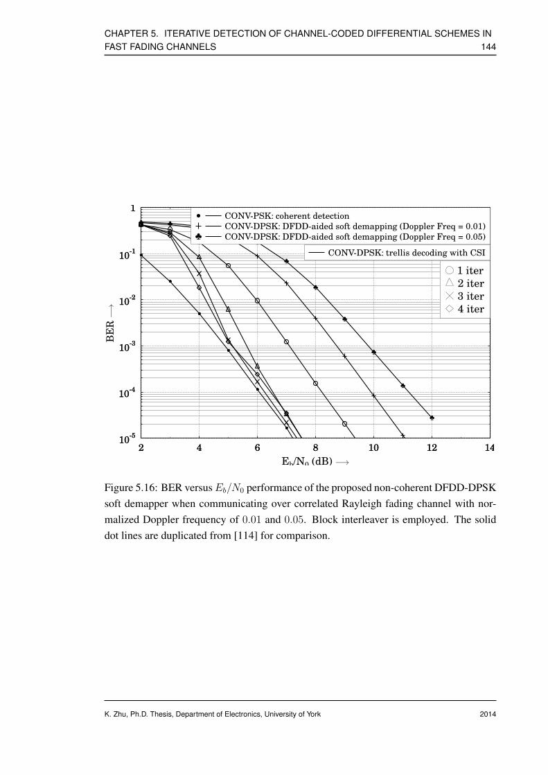
CHAPTER 5. ITERATIVE DETECTION OF CHANNEL-CODED DIFFERENTIAL SCHEMES INFAST FADING CHANNELS 144
10-5
10-4
10-3
10-2
10-1
1
2 4 6 8 10 12 14
♣ ♣♣
♣
♣
♣
♣
♣
♣
♣
♣
10-5
10-4
10-3
10-2
10-1
1
BER
2 4 6 8 10 12 14
Eb/N0 (dB)
CONV-PSK: coherent detection
CONV-DPSK: DFDD-aided soft demapping (Doppler Freq = 0.01)
♣ CONV-DPSK: DFDD-aided soft demapping (Doppler Freq = 0.05)
CONV-DPSK: trellis decoding with CSI
1 iter
2 iter
3 iter
4 iter−→
−→
Figure 5.16: BER versusEb/N0 performance of the proposed non-coherent DFDD-DPSKsoft demapper when communicating over correlated Rayleigh fading channel with nor-malized Doppler frequency of 0.01 and 0.05. Block interleaver is employed. The soliddot lines are duplicated from [114] for comparison.
K. Zhu, Ph.D. Thesis, Department of Electronics, University of York 2014

CHAPTER 5. ITERATIVE DETECTION OF CHANNEL-CODED DIFFERENTIAL SCHEMES INFAST FADING CHANNELS 145
10-5
10-4
10-3
10-2
10-1
1
2 3 4 5 6 7 8 9 10 11 1210
-5
10-4
10-3
10-2
10-1
1
BER
2 3 4 5 6 7 8 9 10 11 12
Eb/N0 (dB)
CONV-PSK: coherent detection
CONV-DPSK: trellis decoding with CSI
CONV-DPSK: trellis decoding with DFDD-aidedchannel estimation (Doppler Freq = 0.01)
1 iter
2 iter
3 iter
4 iter
−→
−→
Figure 5.17: BER versus Eb/N0 performance of the proposed DFDD aided iterative non-coherent trellis detection and decoding of NSC coded DQPSK when communicating overcorrelated Rayleigh fading channel with normalized Doppler frequency of 0.01. Blockinterleaver is employed. The solid dot lines are duplicated from [114] for comparison.
K. Zhu, Ph.D. Thesis, Department of Electronics, University of York 2014

CHAPTER 5. ITERATIVE DETECTION OF CHANNEL-CODED DIFFERENTIAL SCHEMES INFAST FADING CHANNELS 146
10-5
10-4
10-3
10-2
10-1
1
2 3 4 5 6 7 8 9 10 11 1210
-5
10-4
10-3
10-2
10-1
1
BER
2 3 4 5 6 7 8 9 10 11 12
Eb/N0 (dB)
CONV-PSK: coherent detection
CONV-DPSK: trellis decoding with CSI
CONV-DPSK: trellis decoding with DFDD-aidedchannel estimation (Doppler Freq = 0.01)
1 iter
2 iter
3 iter
4 iter
−→
−→
Figure 5.18: BER versus Eb/N0 performance of the proposed DFDD aided iterative non-coherent trellis detection and decoding of NSC coded DQPSK when communicating overcorrelated Rayleigh fading channel with normalized Doppler frequency of 0.01. Sequenceinterleaver is employed. The solid dot lines are duplicated from [114] for comparison.
K. Zhu, Ph.D. Thesis, Department of Electronics, University of York 2014
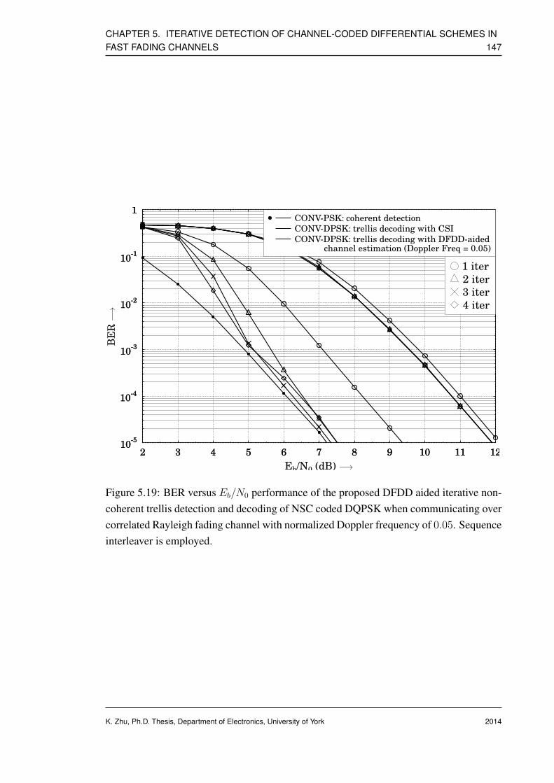
CHAPTER 5. ITERATIVE DETECTION OF CHANNEL-CODED DIFFERENTIAL SCHEMES INFAST FADING CHANNELS 147
10-5
10-4
10-3
10-2
10-1
1
2 3 4 5 6 7 8 9 10 11 1210
-5
10-4
10-3
10-2
10-1
1
BER
2 3 4 5 6 7 8 9 10 11 12
Eb/N0 (dB)
CONV-PSK: coherent detection
CONV-DPSK: trellis decoding with CSI
CONV-DPSK: trellis decoding with DFDD-aidedchannel estimation (Doppler Freq = 0.05)
1 iter
2 iter
3 iter
4 iter
−→
−→
Figure 5.19: BER versus Eb/N0 performance of the proposed DFDD aided iterative non-coherent trellis detection and decoding of NSC coded DQPSK when communicating overcorrelated Rayleigh fading channel with normalized Doppler frequency of 0.05. Sequenceinterleaver is employed.
K. Zhu, Ph.D. Thesis, Department of Electronics, University of York 2014
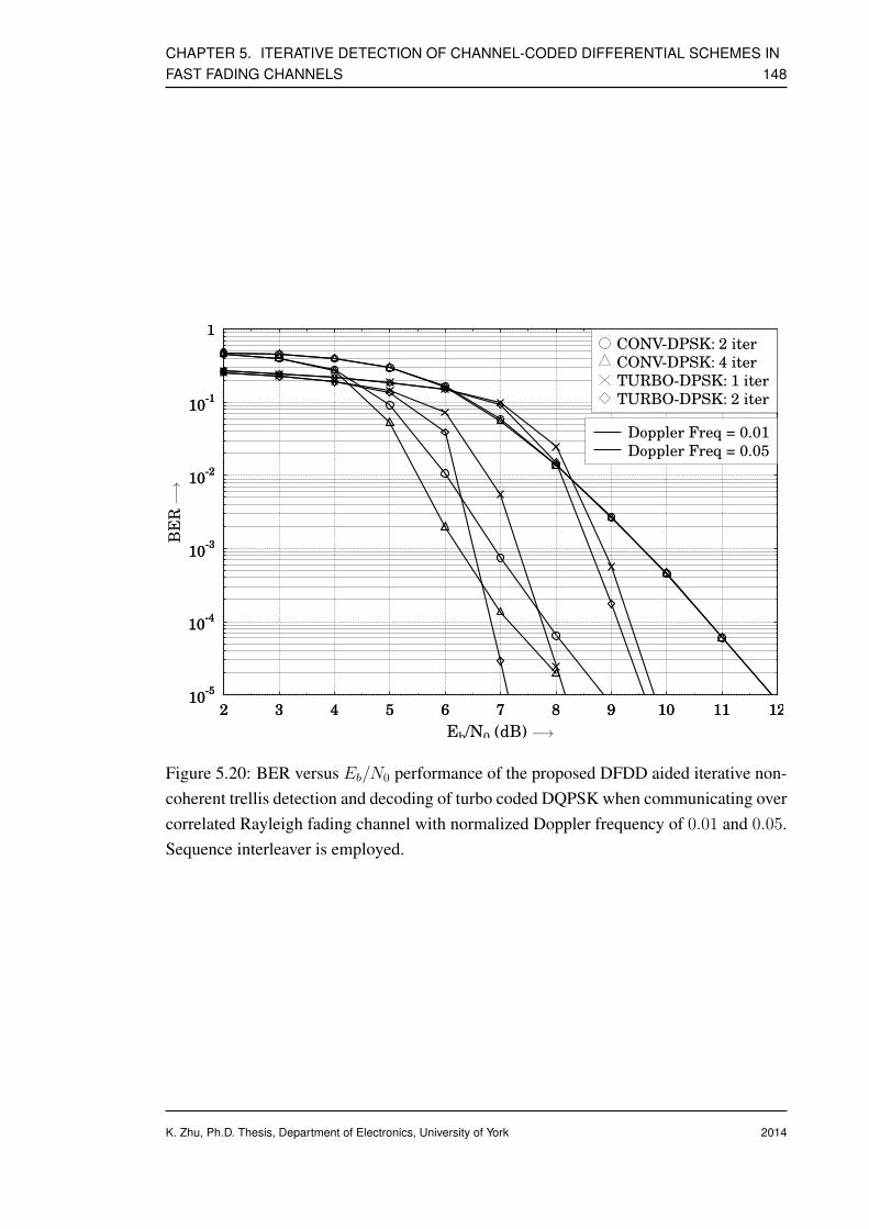
CHAPTER 5. ITERATIVE DETECTION OF CHANNEL-CODED DIFFERENTIAL SCHEMES INFAST FADING CHANNELS 148
10-5
10-4
10-3
10-2
10-1
1
2 3 4 5 6 7 8 9 10 11 1210
-5
10-4
10-3
10-2
10-1
1
BER
2 3 4 5 6 7 8 9 10 11 12
Eb/N0 (dB)
Doppler Freq = 0.01
Doppler Freq = 0.05
CONV-DPSK: 2 iter
CONV-DPSK: 4 iter
TURBO-DPSK: 1 iter
TURBO-DPSK: 2 iter
−→
−→
Figure 5.20: BER versus Eb/N0 performance of the proposed DFDD aided iterative non-coherent trellis detection and decoding of turbo coded DQPSK when communicating overcorrelated Rayleigh fading channel with normalized Doppler frequency of 0.01 and 0.05.Sequence interleaver is employed.
K. Zhu, Ph.D. Thesis, Department of Electronics, University of York 2014

CHAPTER 5. ITERATIVE DETECTION OF CHANNEL-CODED DIFFERENTIAL SCHEMES INFAST FADING CHANNELS 149
5.3 Conclusion
In this chapter, we concentrate on improving the error performance of differentially-modulated PSK systems by exploiting iterative non-coherent detection techniques. Thebenefit of iterative processing allows near-coherent performance when transmitting overslow as well as fast Rayleigh fading channels. DPSK detector essentially works similarlyas a unity-rate convolutional decoder that facilitates exchanging extrinsic informationwith other component SISO decoders in an iterative manner like serial/parallel concate-nated coding schemes. Some distinguished contributions of this chapter are summarizedas follows:
• We first demonstrate that differentially-encoded PSK symbols can be representedby a trellis diagram; therefore, trellis-based SISO decoding algorithm is applicableto provide performance improvement.
• A non-coherent DPSK soft demapper is proposed and studied. By exploiting theconnection between current and previous received symbols, proposed scheme isable to calculate the a-posteriori symbol probabilities even when the channel infor-mation is unavailable at the receiver. Furthermore, the resultant a-posteriori symbolprobabilities are passed to the outer decoder for the sake of achieving iteration gain.Unfortunately, this approach is only suitable for static or very slowly-faded chan-nels due to the assumption used in the derivation h[k] ≈ h[k − 1].
• A simple APP channel estimator is then investigated. Since it takes advantage of thea-posteriori symbol probabilities from the DPSK soft demapper generated by Log-MAP decoding, transmission of training symbols is no longer required. Later, APPchannel estimation algorithm is incorporated in an iterative DPSK trellis decodingstructure to facilitate iterative processing. Simulation results suggest substantialamount of performance gain is available when differential modulation is combinedwith error-correction codes and interleaving.
• A different kind of differential decoding approach based on the decision feedback,hence termed DFDD DPSK trellis decoder, is devised and investigated. Althoughthe derivation of DFDD algorithm is very similar to the principle of multi-symboldifferential detection, the complexity of our novel DFDD DPSK trellis decodingscheme is linearly proportional to the DPSK constellation size. Furthermore, it isconfirmed in simulations that DFDD aided differential decoding scheme is veryrobust in fast fading channels.
K. Zhu, Ph.D. Thesis, Department of Electronics, University of York 2014

Chapter 6
Conclusions
Contents6.1 Summary of Work . . . . . . . . . . . . . . . . . . . . . . . . . . . . 150
6.2 Future Work . . . . . . . . . . . . . . . . . . . . . . . . . . . . . . . 152
6.1 Summary of Work
In this thesis, we primarily concentrate on the design and analysis of low-complexitydistributed STBC and distributed differential STBC for unidirectional and bidirectionalcooperative networks. PLNC and its non-coherent variant, namely differential PLNC, areinvestigated and incorporated in our novel distributed coding systems. Furthermore, sincethe differential techniques generally lead to error rate degradation and poor performancein high mobility applications, several iterative detection and decoding schemes are de-vised and studied to effectively improve the performance of channel-coded differentialPSK under fast fading channels. A brief summary of the contents and major contributionsof each chapter is listed below.
1. To begin with, a novel distributed STBC scheme using ‘decode-and-forward’ relay-ing protocol for multi-relay assisted two-way cooperative communication systemsis presented in Chapter 3. The network topology is similar to the one in [69] wheretwo users simultaneously exchange Alamouti space-time coded signals via a singlepartner with the aid of PLNC, but we relax the constraint that the source nodes are
K. Zhu, Ph.D. Thesis, Department of Electronics, University of York
1502014
CHAPTER 6. CONCLUSIONS 151
supported by multiple co-located antennas. We show that our proposed scheme canstill achieve full diversity order when each node acts as a single antenna assistedmobile unit. A simple selection relaying or opportunistic relaying protocol is ap-propriately designed to effectively circumvent the error propagation inflicted by therelay nodes. More specifically, an error detection code (such as CRC) based selec-tion relaying strategy is proposed to retain the orthogonality of the distributed STBCcodewords as well as guarantee the full diversity order is achieved at the destina-tion without employing any sophisticated channel codes to protect the source-to-relay link. PLNC is employed to guarantee that the information exchange betweentwo users via a single or multiple relays could be fulfilled within two time slots.Hence, this novel cooperative communication scheme for two-way relay channelscan achieve significant throughput and spectral efficiency improvements. Theoret-ical end-to-end BEP performance of our proposed distributed STBC scheme overtwo-way relay channel is investigated using the MGF based approach. Tight upperand lower bounds of the average end-to-end BEP are derived. We then extend ouranalysis and obtain the exact BEP.
2. In Chapter 4, a novel distributed differential STBC scheme based on ‘decode-and-forward’ relaying protocol is proposed and investigated in the context of multi-relayassisted cooperative networks. Discussions start from the unidirectional scenario,system model is identical to the one assumed in Chapter 3, in which two usersintend to communicate via relay nodes. The encoding and decoding proceduresfor the distributed differential STBC are elaborated. CRC-based selection relayingprotocol is invoked at each relay node to retain the orthogonality of the distributeddifferential STBC codewords. It is confirmed by both Monte-Carlo simulation re-sults as well as numerical analysis, proposed distributed differential STBC schemeis capable of exploiting full diversity gain with a cluster of single-antenna assistednodes or users. Furthermore, a Turbo-coded distributed differential STBC schemeis presented to suppress the sensitivity with respect to the frame length. Discus-sions are later extended to two-way relaying scenario. Novel non-coherent PLNCis also proposed to assist the direct extraction of network-coded symbols withoutthe need of recovering the information from two users explicitly and independently.Consequently, information exchange process between two users via a single or mul-tiple relays can be fulfilled within two time slots, which could result in significantthroughput gain.
3. Chapter 5 mostly concentrates on the differential encoding and non-coherent de-coding techniques. Two channel estimation methods, namely APP channel esti-mation as well as DFDD channel estimation, are introduced and incorporated inthe uncoded and coded DPSK systems. It is demonstrated in Chapter 5 that the
K. Zhu, Ph.D. Thesis, Department of Electronics, University of York 2014

CHAPTER 6. CONCLUSIONS 152
differential detection is capable of outperforming the coherent counterparts whencombined with error-correction codes and interleaving. The APP channel estimatorcomputes the a-posteriori symbol probabilities with arbitrary channel coefficientsat the beginning of the first iteration. The up-to-date a-posteriori symbol proba-bilities are invoked to update the channel estimates after each iteration. The APPchannel estimator is easy to implement yet less robust in fast fading channels. Asa result, DFDD channel estimation is presented as a solution, in which the deci-sion of one specific symbol is based on N previously-recovered DPSK symbols. Itis shown that differentially-encoded PSK symbols can be represented by a trellisdiagram, therefore, standard trellis-based decoding algorithm is feasible. Severalconcatenated coding schemes using differential encoder as the inner encoder andFEC encoder as the outer encoder are studied. When Turbo code is selected as theouter code, DFDD aided DPSK trellis decoder exhibits its robustness under fastfading channels.
6.2 Future Work
Some suggestions about future work based on this thesis are given as follows.
1. Similar to DPSK, USTM also has recursive nature, hence could be represented bytrellis and decoded with trellis decoding algorithm. It is an interesting idea to in-vestigate the application of DFDD channel estimator in a multiple-antenna system.
2. The developed iterative differential decoding techniques can be used in a multi-hopnon-coherent cooperative network to reinforce the reliability of cooperating link,especially when fast fading channel is assumed.
3. It is also interesting to investigate if the above-mentioned iterative USTM systemis able to work in a distributed way and be extended to two-way relay scenario ifpossible.
K. Zhu, Ph.D. Thesis, Department of Electronics, University of York 2014
Appendices
K. Zhu, Ph.D. Thesis, Department of Electronics, University of York
1532014
Appendix A
Derivation of Upper and Lower Boundsof the Average End-To-End BEP
Take the tight lower bound P (L)EtoE for example, expanding the first term of the left hand
side of Eq. (3.34) and after proper arrangements and simplifications based on the sym-metrical property of system architecture, we can obtain
E[(
1− P (U)MAC,r1
)(1− P (U)
MAC,r2
) (P t1DSTBC + P t2
DSTBC
)]
= E[2P t1
DSTBC
(1− P (U)
MAC,r1− P (U)
MAC,r2+ P
(U)MAC,r1
P(U)MAC,r2
)]
= E[2P t1
DSTBC − 2P t1DSTBCP
(U)MAC,r1
− 2P t1DSTBCP
(U)MAC,r2
+ 2P t1DSTBCP
(U)MAC,r1
P(U)MAC,r2
]
= 2E[P t1DSTBC
]− 2E
[P t1DSTBCP
(U)MAC,r1
]− 2E
[P t1DSTBCP
(U)MAC,r2
]
+ 2E[P t1DSTBCP
(U)MAC,r1
P(U)MAC,r2
], (A.1)
The first term of Eq. (A.1) is the unconditional BEP of conventional Alamouti STBCtransmitting over Rayleigh fading channel, its solution is given by [27]
E[P t1DSTBC
]=
(1− λ
2
)2
(λ+ 2) , λ =
√γDSTBC
2 + γDSTBC(A.2)
where γDSTBC is the average received SNR at the destinations when DSTBC scheme isinvoked during the BC phase.
The expectation in the second term of Eq. (3.34) can be computed by replacing P (U)MAC,r1
K. Zhu, Ph.D. Thesis, Department of Electronics, University of York
1542014

APPENDIX A. DERIVATION OF UPPER AND LOWER BOUNDS OF THE AVERAGEEND-TO-END BEP 155
with Eq. (3.29) and taking an integral from 0 to positive infinity, which gives
E[P T1AlamoutiP
(U)MAC,r1
]
=
∫ ∞
0
∫ ∞
0
Pb(γDSTBC |hr1d1 , hr2d1)Pb(γs1r1|hs1r1)p(γDSTBC)p(γs1r1) dγs1r1 dγDSTBC
+
∫ ∞
0
∫ ∞
0
Pb(γDSTBC |hr1d1 , hr2d1)Pb(γs2r1|hs2r1)p(γDSTBC)p(γs2r1) dγs2r1 dγDSTBC .
(A.3)
The first term of Eq. (A.3) can be addressed using the popular MGF-based approachwhich is briefly generalized as follows∫ ∞
0
∫ ∞
0
Pb(γDSTBC |hr1d1 , hr2d1)Pb(γs1r1|hs1r1)p(γDSTBC)p(γs1r1) dγs1r1 dγDSTBC
=
∫ ∞
0
∫ ∞
0
Q(√γDSTBC)Q(
√2γs1r1)p(γDSTBC)p(γs1r1) dγs1r1 dγDSTBC
=1
π2
∫ π2
0
∫ π2
0
[∫ ∞
0
exp
(−γDSTBC
2 sin2 ϕ
)p(γDSTBC) dγDSTBC
]
×[∫ ∞
0
exp(− γs1r1
2 sin2 θ
)p(γs1r1) dγs1r1
]dθ dϕ
=1
π2
∫ π2
0
∫ π2
0
MγDSTBC
(− 1
2 sin2 ϕ
)Mγs1r1
(− 1
2 sin2 θ
)dθ dϕ
=1
π2
∫ π2
0
∫ π2
0
(1 +
γDSTBC2 sin2 ϕ
)−2(1 +
γs1r12 sin2 θ
)−1
dθ dϕ
=1
2
(1− λ
2
)2
(λ+ 2)
(1−
√γs1r1
1 + γs1r1
), λ =
√γDSTBC
2 + γDSTBC(A.4)
where p(γDSTBC) denotes the PDF of the instantaneous received SNR γDSTBC having achi-squared distribution with 2L degrees of freedom and p(γs1r1) represents the instanta-neous received SNR γs1r1 with an exponentially distributed PDF. If nT and nR indicatethe number of transmit antennas and receive antennas respectively, we have L = nT ×nR.Furthermore, by definition, the semi-infinite integrals in square brackets are the MGF ofthe instantaneous SNR. It is discussed in [16] that the results ofMγDSTBC (s) andMγs1r1
(s)
are given by
MγDSTBC (s) = (1− sγDSTBC)−L, s > 0 (A.5)
Mγs1r1(s) = (1− sγs1r1)−1, s > 0 (A.6)
where γs1r1 is the average received SNR at relay node r1. We can solve the rest of termsindividually in a similar way and sum up the solution of each term. The final expres-sion for the upper and lower bounds of the average end-to-end BEP for our proposeddistributed STBC scheme can be formulated as Eq. (3.35) and Eq. (3.36).
K. Zhu, Ph.D. Thesis, Department of Electronics, University of York 2014
Glossary
4G The Fourth Generation
AF Amplify-and-Forward
APP A Posteriori Probability
AWGN Additive White Gaussian Noise
BER Bit Error Ratio
BEP Bit Error Probability
BLAST Bell labs LAyered Space Time
BPSK Binary Phase Shift Keying
BS Base Station
CCMC Continuous-input Continuous-output Memoryless Channel
CDMA Code Division Multiple Access
CRC Cyclic Redundancy Check
CSI Channel State Information
D-BLAST Diagonal BLAST
DCMC Discrete-input Continuous-output Memoryless Channel
DF Decode-and-Forward
DFDD Decision Feedback Differential Detection
DLST Diagonal Layered Space-Time (Code)
DOSTBC Differential Orthogonal Space-Time Block Code
K. Zhu, Ph.D. Thesis, Department of Electronics, University of York
1562014
Glossary 157
DPSK Differential Phase Shift Keying
DSP Digital Signal Processing
DSTBC Differential Space-Time Block Code
DSTC Differential Space-Time Code
DUSTM Differential Unitary Space-Time Modulation
FCC Federal Communications Commission
FEC Forward-Error-Correction
FER Frame Error Ratio
GF Galois Field
GSM Global System for Mobile communications
HLST Horizontal Layered Space-Time (Code)
Hz Hertz
ISI Inter-Symbol Interference
ITU International Telecommunication Union
LDC Linear Dispersion Code
LDPC Low Density Parity Check
LLR Log-Likelihood Ratio
LST Layered Space-Time (Code)
LTE Long-Term Evolution
MAP Maximum a Posteriori
MGF Moment Generating Function
ML Maximum Likelihood
MIMO Multiple-Input Multiple-Output
MMSE Minimum Mean Squared Error
MRC Maximal Ratio Combining
K. Zhu, Ph.D. Thesis, Department of Electronics, University of York 2014
Glossary 158
MS Mobile Station
MSE Mean Squared Error
MUD Multiuser Detection
NC Network Coding
OSTBC Orthogonal Space-Time Block Code
PDF Probability Density Function
PEP Pairwise Error Probability
PHY Physical Layer
PLNC Physical-Layer Network Coding
PSD Power Spectral Density
PSK Phase Shift Keying
QAM Quadrature Amplitude Modulation
QoS Quality of Service
QOSTBC Quasi-orthogonal Space-Time Block Code
QPSK Quadrature Phase Shift Keying
RSC Recursive-Systematic Code
SCCC Serially Concatenated Convolutional Codes
SISO Soft-in Soft-out (Single-Input Sinlge-Output)
SM Spatial Multiplexing
SNR Signal to Noise Ratio
SP Set Partitioning
STBC Space-Time Block Code
STC Space-Time Code
STTC Space-Time Trellis Code
TC Turbo Code
K. Zhu, Ph.D. Thesis, Department of Electronics, University of York 2014

Glossary 159
TLST Threaded Layered Space-Time (Code)
UMTS Universal Mobile Telecommunications System
USTM Unitary Space-Time Modulation
VAA Virtual Antenna Array
V-BLAST Vertical BLAST
VLST Vertical Layered Space-Time (Code)
WCDMA Wideband Code Division Multiple Access
WSN Wireless Sensor Network
K. Zhu, Ph.D. Thesis, Department of Electronics, University of York 2014

Bibliography
[1] B. Sanou, “The World in 2013: ICT Facts and Figures,” Annual Report, In-ternational Telecommunication Union (ITU), 2013. http://www.itu.int/en/ITU-D/Statistics/Documents/facts/ICTFactsFigures2013-e.pdf.
[2] 3GPP, 3rd Generation Patnership Project (3GPP); Technical Specification GroupRadio Access Network Physical Channels and Mapping of Transport Channelsonto Physical Channels (TDD) (3G TS 25.221 version 3.0.0) (www.3gpp.org), Oc-tober 1999.
[3] “Ofcom Announces Winners of the 4G Mobile Auction,” February 2013.http://media.ofcom.org.uk/2013/02/20/ofcom-announces-winners-of-the-4g-mobile-auction/.
[4] B. Sklar, Digital Communications–Fundamentals and Applications. EnglewoodCliffs, NJ, USA: Prentice-Hall, 2nd ed., 2001.
[5] C. E. Shannon, “A Mathematical Theory of Communication,” Bell Labs TechnicalJournal, pp. 379–427, 1948.
[6] C. Berrou and A. Glavieux and P. Thitimajshima, “Near Shannon Limit Error-Correcting Coding and Decoding: Turbo Codes,” in Proceedings of the Interna-tional Conference on Communications, (Geneva, Switzerland), pp. 1064–1070,May 1993.
[7] R. Gallager, “Low-Density Parity-Check Codes,” IEEE Transactions on Informa-tion Theory, pp. 21–28, 1962.
[8] D. MacKay and R. Neal, “Near Shannon Limit Performance of Low Density ParityCheck Codes,” Electronics Letters, pp. 457–458, 1997.
[9] E. Telatar, “Capacity of Multi-antenna Gaussian Channels,” European Transac-tions on Telecommunication, vol. 10, pp. 585–595, Nov–Dec 1999.
[10] J. Winters, “On the Capacity of Radio Communication Systems with Diversity ina Rayleigh Fading Environment,” IEEE Journal on Selected Areas in Communica-tions, vol. 5, pp. 0733–8716, June 1987.
K. Zhu, Ph.D. Thesis, Department of Electronics, University of York
1602014
BIBLIOGRAPHY 161
[11] A. Paulraj and T. Kailath, “Increasing Capacity in Wireless Broadcast Sys-tems using Distributed Transmission/Directional Reception (DTDR).” U.S. PatentNo. 5345599 A, Sep 6, 1994.
[12] J. Winters, J. Salz, and R. Gitlin, “The Impact of Antenna Diversity on the Capac-ity of Wireless Communication Systems,” IEEE Transactions on Communications,vol. 42, pp. 1740–1751, March 1994.
[13] G. J. Foschini and M. J. Gans, “On Limits of Wireless Communications in a Fad-ing Environment When Using Multiple Antennas,” Wireless Personal Communica-tions, vol. 6, pp. 311–335, March 1998.
[14] T. L. Marzetta and B. M. Hochwald, “Capacity of a Mobile Multiple-AntennaCommunication Link in Rayleigh Flat Fading,” IEEE Transactions on InformationTheory, vol. 45, pp. 139–157, January 1999.
[15] A. Goldsmith, S. Jafar, N. Jindal, and S. Vishwanath, “Capacity Limits of MIMOChannels,” IEEE Journal on Selected Areas in Communications, vol. 21, pp. 684–702, June 2003.
[16] M.K. Simon and M.S. Alouini, Digital Communication over Fading Channels.Hoboken, NJ, USA: John Wiley & Sons, 2nd ed., 2004.
[17] M. Mouly and M. Pautet, eds., The GSM System for Mobile Communications.Olympia, USA: Telecom Publishing, 1992.
[18] A. Wittneben, “Base Station Modulation Diversity for Digital SIMULCAST,” inProceedings of IEEE Vehicular Technology Conference, pp. 505–511, May 1993.
[19] N. Seshadri and J. Winters, “Two Signaling Schemes for Improving the ErrorPerformance of Frequency-Division-Duplex (FDD) Transmission Systems UsingTransmitter Antenna Diversity,” International Journal of Wireless Information Net-works, vol. 1, pp. 49–60, January 1994.
[20] V. Tarokh, N. Seshadri and A. R. Calderbank, “Space-time Codes for High DataRate Wireless Communication: Performance Criterion and Code Construction,”IEEE Transactions on Information Theory, vol. 44, pp. 744–765, March 1998.
[21] S. M. Alamouti, “A Simple Transmit Diversity Technique for Wireless Communi-cations,” IEEE Journal on Selected Areas in Communications, vol. 16, pp. 1451–1458, October 1998.
[22] V. Tarokh, H. Jafarkhani, and A. R. Calderbank, “Space-Time Block Coding forWireless Communications: Performance Results,” IEEE Journal on Selected Areasin Communications, vol. 17, pp. 451–460, March 1999.
[23] V. Tarokh, H. Jafarkhani, and A. R. Calderbank, “Space-time Block Codesfrom Orthogonal Designs,” IEEE Transactions on Information Theory, vol. 45,pp. 1456–1467, May 1999.
K. Zhu, Ph.D. Thesis, Department of Electronics, University of York 2014

BIBLIOGRAPHY 162
[24] G. J. Foschini, “Layered Space-Time Architecture for Wireless Communication ina Fading Environment When Using Multi-Element Antennas,” Bell Labs TechnicalJournal, vol. 6, no. 2, pp. 41–59, 1996.
[25] L. Zheng and D. Tse, “Diversity and Multiplexing: A Fundamental Tradeoff inMultiple-Antenna Channels,” IEEE Transactions on Information Theroy, vol. 49,pp. 1073–1096, May 2003.
[26] B. L. Y. L. Hanzo, T. H. Liew, Turbo Coding, Turbo Equalisation and Space-TimeCoding for Transmission over Wireless Channels. Hoboken, NJ, USA: John Wiley& Sons, 2002.
[27] B. Vucetic and J. Yuan, Space-Time Coding. Southern Gate, Chichester, England:John Wiley & Sons, 2003.
[28] E.G. Larsson and P. Stoica, Space-Time Block Coding for Wireless Communica-tions. Cambridge, New York, Melbourne, Madrid, Cape Town, Singapore, SoPaulo: Cambridge University Press, 2003.
[29] W. C. Jakes, ed., Microwave Mobile Communications. New York, USA: JohnWiley & Sons, 1974.
[30] Z. Liu, G.B. Giannakis, S. Zhou and B. Muquet, “Space-Time Coding for Broad-band Wireless Communications,” Wireless Communications and Mobile Comput-ing, vol. 1, no. 1, pp. 35–53, 2001.
[31] N. S. A.F. Naguib and A. Calderbank, “Increasing Data Rate over Wireless Chan-nels: Space-time Coding and Signal Processing for High Data Rate Wireless Com-munications,” IEEE Signal Processing Magazine, vol. 17, no. 3, pp. 76–92, 2000.
[32] G.J. Foschini, D. Chizhik, M.J. Gans, C. Papadias and R.A. Valenzuela, “Analy-sis and Performance of Some Basic Space-Time Architectures,” IEEE Journal onSelected Areas in Communications, vol. 21, pp. 303–320, April 2003.
[33] H. E. Gamal and A. Hammons, “A New Approach to Layered Space-Time Cod-ing and Signal Processing,” IEEE Transactions on Information Theory, vol. 47,pp. 2321–2334, September 2001.
[34] R. V. G.D. Golden, G.J. Foschini and P. Wolniansky, “Detection Algorithm andInitial Laboratory Results Using V-BLAST Space-Time Communication Architec-ture,” IEE Electronics Letters, vol. 35, pp. 14–16, January 1999.
[35] R. V. G.J. Foschini, G.D. Golden and P. Wolniansky, “Simplified Processing forHigh Spectral Efficiency Wireless Communications Employing Multi-element Ar-rays,” IEEE Journal on Selected Areas in Communications, vol. 17, pp. 1841–1852,November 1999.
[36] G. G. P.W. Wolniansky, G.J. Foschini and R. Valenzuela, “V-BLAST: An Architec-ture for Realizing Very High Data Rates over the Rich-scattering Wireless Cannel,”
K. Zhu, Ph.D. Thesis, Department of Electronics, University of York 2014
BIBLIOGRAPHY 163
in Proceedings of International Symposium on Signals, Systems and Electronics(ISSSE), pp. 295–300, September 1998.
[37] B. Hassibi and B. Hochwald, “High-Rate Codes that Are Linear in Space andTime,” IEEE Transactions on Information Theory, vol. 48, pp. 1804–1824, July2002.
[38] H.J. Chen, A. Haimovich and J.A. Sjogren, “Turbo Space-time Codes with TimeVarying Linear Transformations,” IEEE Transactions on Wireless Communica-tions, vol. 6, pp. 486–493, February 2007.
[39] H. G. M.O. Damen and N. Beaulieu, “Linear Threaded Algebraic Space-time Con-stellations,” IEEE Transactions on Information Theory, vol. 49, pp. 2372–2388,October 2003.
[40] X. Ma and G. Giannakis, “Full-Diversity Full-Rate Complex-Field Space-TimeCoding,” IEEE Transactions on Signal Processing, vol. 51, pp. 2917–2930,November 2003.
[41] R.H. Gohary and T.N. Davidson, “Design of Linear Dispersion Codes: AsymptoticGuidelines and Their Implementation,” IEEE Transactions on Wireless Communi-cations, vol. 4, pp. 2892–2906, November 2005.
[42] R. Heath and A. Paulraj, “Linear Dispersion Codes for MIMO Systems Based onFrame Theory,” IEEE Transactions on Signal Processing, vol. 50, pp. 2429–2441,October 2002.
[43] B. Hassibi and B. Hochwald, “How Much Training Is Needed in Multiple-antennaWireless Links?,” IEEE Transactions on Information Theory, vol. 49, pp. 951–963,April 2003.
[44] B. Hochwald and T. Marzetta, “Unitary Spacetime Modulation for Multiple-antenna Communications in Rayleigh Flat Fading,” IEEE Transactions on Infor-mation Theory, vol. 46, pp. 543–564, March 2000.
[45] B.M. Hochwald, T.L. Marzetta, T.J. Richardson, W. Sweldens and R. Urbanke,“Systematic Design of Unitary Spacetime Constellation,” IEEE Transactions onInformation Theory, vol. 46, pp. 1962–1973, September 2000.
[46] B. Hughes, “Differential Space-Time Modulation,” IEEE Transactions on Infor-mation Theory, vol. 46, pp. 2567–2578, November 2000.
[47] B. Hochwald and W. Sweldens, “Differential Unitary Spacetime Modulation,”IEEE Transactions on Communications, vol. 48, pp. 2041–2052, December 2000.
[48] W. S. K.L. Clarkson and A. Zheng, “Fast Multiple-antenna Differential Decoding,”IEEE Transactions on Communications, vol. 49, pp. 253–261, February 2001.
K. Zhu, Ph.D. Thesis, Department of Electronics, University of York 2014
BIBLIOGRAPHY 164
[49] T. Himsoon, W. Su and K.J.R Liu, “Differential Unitary Space-time Signal DesignUsing Matrix Rotation Structure,” IEEE Signal Processing Letters, vol. 12, pp. 45–48, January 2005.
[50] T.P. Soh, C.S. Ng and P.Y. Kam, “Improved Signal Constellations for DifferentialUnitary Space-time Modulations with More Than Two Transmit Antennas,” IEEECommunications Letters, vol. 9, pp. 7–9, January 2005.
[51] S. Cheng, A. Nallanathan and P.Y. Kam, “A New Class of Signal Constellations forDifferential Unitary Space-time Modulation (DUSTM),” IEEE CommunicationsLetters, vol. 8, pp. 1–3, January 2004.
[52] X.-B. Liang and X.-G. Xia, “Unitary Signal Constellations for Differential Space-time Modulation with Two Transmit Antennas: Parametric Codes, Optimal De-signs, and Bounds,” IEEE Transactions on Information Theory, vol. 48, pp. 2291–2322, August 2002.
[53] V. Tarokh and H. Jafarkhani, “A Differential Detection Scheme for Transmit Diver-sity,” IEEE Journal on Selected Areas in Communications, vol. 18, pp. 1169–1174,July 2000.
[54] H. Jafarkhani and V. Tarokh, “Multiple Transmit Antenna Differential Detectionfrom Generalized Orthogonal Designs,” IEEE Transactions on Information Theory,vol. 47, pp. 2626–2631, September 2001.
[55] G. Ganesan and P. Stoica, “Differential Detection Based on Space-time BlockCodes,” Wireless Personal Communications, vol. 21, pp. 163–180, 2002.
[56] G. Ganesan and P. Stoica, “Differential Modulation Using Space-time BlockCodes,” IEEE Signal Processing Letters, vol. 9, no. 2, pp. 57–60, 2002.
[57] D. Divsalar and M. K. Simon, “Multiple-Symbol Differential Detection of MPSK,”IEEE Transactions on Communications, vol. 38, pp. 300–308, March 1990.
[58] A. Sendonaris, E. Erkip, and B. Aazhang, “Increasing Uplink Capacity via UserCooperation Diversity,” in Proceedings of IEEE International Symposium on In-formation Theory, (Cambridge, MA, USA), August 1998.
[59] A. Sendonaris, E. Erkip, and B. Aazhang, “User Cooperation Diversity Part I: Sys-tem Description,” IEEE Transactions on Communications, vol. 51, pp. 1927–1938,November 2003.
[60] A. Sendonaris, E. Erkip, and B. Aazhang, “User Cooperation Diversity Part II:Implementation Aspects and Performance Analysis,” IEEE Transactions on Com-munications, vol. 51, pp. 1939–1948, November 2003.
[61] J. N. Laneman, D. N. C. Tse, and G. W. Wornell, “Cooperative Diversity in Wire-less Networks: Efficient Protocols and Outage Behavior,” IEEE Transactions onInformation Theory, vol. 50, pp. 3062–3080, December 2004.
K. Zhu, Ph.D. Thesis, Department of Electronics, University of York 2014
BIBLIOGRAPHY 165
[62] E. Zimmermann, P. Herhold and G. Fettweis, “On the Performance of Coopera-tive Diversity Protocols in Practical Wireless Systems,” in Proceedings of IEEEVehicular Technology Conference (VTC), vol. 4, (Orlando, USA), pp. 2212–2216,October 2003.
[63] H. E. Gamal and D. Aktas, “Distributed Space-Time Filtering for CooperativeWireless Networks,” in Proceedings of IEEE Global Conference on Communica-tions, vol. 4, (San Francisco), pp. 1826–1830, December 2003.
[64] J. N. Laneman and G. W. Wornell, “Distributed Space-Time-Coded Protocols forExploiting Cooperative Diversity in Wireless Networks,” IEEE Transactions onInformation Theory, vol. 49, pp. 2415–2425, October 2003.
[65] M. Dohler and Y. Li, Cooperative Communications: Hardware, Channel and PHY.New York, USA: John Wiley & Sons, 2010.
[66] A. H. Bastami and A. Olfat, “Optimal SNR-based Selection Relaying Schemein Multi-Relay Cooperative Networks with Distributed Space-Time Coding,” IETCommunications, vol. 4, pp. 619–630, April 2010.
[67] T. Cui, F. Gao, T. Ho, and A. Nallanathan, “Distributed Space-Time Coding forTwo-Way Wireless Relay Networks,” IEEE Transactions on Signal Processing,vol. 57, pp. 658–671, February 2009.
[68] Y. Jing and B. Hassibi, “Distributed Space-Time Coding in Wireless Relay Net-works,” IEEE Transactions on Wireless Communications, vol. 5, pp. 3524–3536,December 2006.
[69] D. To, J. Choi, and I. Kim, “Error Probability Analysis of Bidirectional RelaySystems Using Alamouti Scheme,” IEEE Communication Letters, vol. 14, pp. 758–760, August 2010.
[70] T. Koike-Akino, P. Popovski, and V. Tarokh, “Denoising Maps and Constella-tions for Wireless Network Coding in Two-Way Relaying Systems,” in Proceed-ings of Global Conference on Communications (GlobeCom), (New Orleans, USA),pp. 3790–3794, December 2008.
[71] C. E. Shannon, “Two-way Communication Channels,” in Proceedings of the FourthBerkeley Symposium on Mathematical Statistics and Probability, vol. 1, (Berkeley,USA), pp. 611–644, 1961.
[72] R. Ahlswede, N. Cai, S.-Y. R. Li, and R. W. Yeung, “Network Information Flow,”IEEE Transactions on Information Theory, vol. 46, pp. 1204–1216, July 2000.
[73] R. Koetter and M. Medard, “An Algebraic Approach to Network Coding,”IEEE/ACM Transactions on Networking, vol. 11, pp. 782–795, October 2003.
[74] S.-Y. R. Li, R. W. Yeung, and N. Cai, “Linear Network Coding,” IEEE Transactionson Information Theory, vol. 49, pp. 371–381, February 2003.
K. Zhu, Ph.D. Thesis, Department of Electronics, University of York 2014

BIBLIOGRAPHY 166
[75] P. Popovski and H. Yomo, “Wireless Network Coding by Amplify-and-Forwardfor Bi-directional Traffic Flows,” IEEE Communication Letters, vol. 11, pp. 16–18, January 2007.
[76] B. Rankov and A. Wittneben, “Spectral Efficient Protocols for Half-duplex FadingRelay Channels,” IEEE Journal on Selected Areas in Communications, vol. 25,pp. 379–389, February 2007.
[77] S. Zhang, S. C. Liew, and P. P. Lam, “Physical Layer Network Coding,” in Pro-ceedings of MobiCom’06: The 12th annual international conference on mobilecomputing and networking, (New York, NY, USA), pp. 358–365, 2006.
[78] H. Ochiai, P. Mitran, and V. Tarokh, “Design and Analysis of Collaborative Diver-sity Protocols for Wireless Sensor Networks,” in Proceedings of IEEE VehicularTechnology Conference (VTC), (Los Angeles, USA), pp. 4645–4649, 2004.
[79] A. Richardson, WCDMA Design Handbook. Cambridge, New York, Melbourne,Madrid, Cape Town, Singapore, So Paulo: Cambridge University Press, 2011March.
[80] D. W. N. Cam-Winget, R. Housley and J. Walker, “Security Flaws in 802.11 DataLink Protocols,” Communications of the ACM, vol. 46, pp. 35–39, May 2003.
[81] M. Ju and I. Kim, “Error Performance Analysis of BPSK Modulation in Physical-Layer Network-Coded Bidirectional Relay Networks,” IEEE Transactions on Com-munications, vol. 58, pp. 2770–2775, October 2010.
[82] K. Lu, S. Fu, Y. Qian, and H. Chen, “SER Performance Analysis for Physical LayerNetwork Coding over AWGN Channels,” in Proceedings of Global Conference onCommunications (GlobeCom), (Honolulu, Hawaii, USA), December 2009.
[83] M. Park, I. Choi, and I. Lee, “Exact BER Analysis of Physical Layer Network Cod-ing for Two-Way Relay Channels,” in Proceedings of IEEE Vehicular TechnologyConference (VTC), (Budapest, Hungary), May 2011.
[84] R. Freeman, Fundamentals of Telecommunications. New York, USA: John Wiley& Sons, 2nd ed., May 2005.
[85] A. Bletsas, A. Khisti, D. P. Reed and A. Lippman, “A simple Cooperative DiversityMethod Based on Network Path Selection,” IEEE Journal on Selected Areas inCommunications, vol. 24, pp. 659–672, March 2006.
[86] H. M. P. Tarasak and V. K. Bhargava, “Differential Modulation for Two-User Co-operative Diversity Systems,” in Proceedings of IEEE Global Conference on Com-munications, vol. 5, (Dallas), pp. 3389–3393, December 2004.
[87] B. M. Hochwald and W. Sweldens, “Differential Unitary Space-Time Modulation,”IEEE Transactions on Communications, vol. 48, pp. 2041–2052, December 2000.
K. Zhu, Ph.D. Thesis, Department of Electronics, University of York 2014

BIBLIOGRAPHY 167
[88] S. J. Alabed and M. Pesavento and A. B. Gershman, “Distributed DifferentialSpace-Time Coding Techniques for Two-Way Wireless Relay Networks,” in Pro-ceedings of IEEE International Workshop on Computational Advances in Multi-Sensor Adaptive Processing (CAMSAP), (San Juan, Puerto Rico), pp. 1–5, Decem-ber 2011.
[89] Z. Utkovski and G. Yammine and J. Lindner, “A Distributed Differential Space-Time Coding Scheme for Two-Way Wireless Relay Networks,” in InternationalSymposium on Information Theory, (Seoul, Korea), pp. 1–5, July 2009.
[90] R1-070462, Ericsson, “QPP Interleaver Design for LTE Turbo Coding,” TS 36.212v8.3.0, 3GPP RAN1, Jan. 14-19, 2007. Sorrento, Italy.
[91] O. Takeshita, “A New Metric for Permutation Polynomial Interleavers,” IEEE In-ternational Symposium on Information Theory (ISIT06), pp. 1983–1987, July 2006.
[92] , “3GPP Technical Specification: Group Radio Access Network, Evolved Univer-sal Terrestrial Radio Access, Multiplexing and Channel Coding (Release 8),” TS36.212 v8.3.0, , May 2007. .
[93] S. Lin and D.J. Costello, Error Control Coding (Second Edition). Upper SaddleRiver, NJ, USA: Prentice Hall, 2004 May.
[94] W. Guan and K. J. R. Liu, “Performance Analysis of Two-Way Relaying withNon-coherent Differential Modulation,” IEEE Transactions on Wireless Commu-nications, vol. 10, pp. 2004–2014, June 2011.
[95] T. Cui, F. Gao, and C. Tellambura, “Differential Modulation for Two-Way WirelessCommunications: A Perspective of Differential Network Coding at the PhysicalLayer,” IEEE Transactions on Communications, vol. 57, pp. 2977–2987, October2009.
[96] M. C. Valenti, D. Torrieri, and T. Ferrett, “Noncoherent Physical-Layer NetworkCoding with FSK Modulation: Relay Receiver Design Issues,” IEEE Transactionson Communications, vol. 59, pp. 2595–2604, September 2011.
[97] K. Zhu and A. G. Burr, “Relay Selection aided Distributed Space-Time Block Codefor Two-Way Relay Channel with Physical-Layer Network Coding,” in Proceed-ings of IEEE Vehicular Technology Conference (VTC), (Budapest, Hungary), pp. 1–5, May 2011.
[98] P. Robertson, “Illuminating the Structure of Code and Decoder of Systematic(Turbo) Codes,” IEEE Globecom, pp. 1298–1303, 1994.
[99] L. R. Bahl, J. Cocke, F. Jelinek and J. Raviv, “Optimal Decoding of LinearCodes for Minimal Symbol Error Rate,” IEEE Transactions on Information The-ory, vol. 20, pp. 284–287, March 1974.
K. Zhu, Ph.D. Thesis, Department of Electronics, University of York 2014

BIBLIOGRAPHY 168
[100] G. Forney, “The Viterbi Algorithm,” Proceedings of the IEEE, vol. 61, pp. 268–278, March 1973.
[101] C. Berrou, A. Glavieux and P. Thitimajshima, “Near Shannon Limit Error-Correcting Coding and Decoding: Turbo Codes,” in Proceedings of IEEE Inter-national Conference on Communications, (Geneva), pp. 1064–1070, May 1993.
[102] P. Robertson, E. Villebrun, and P. Hoher, “A Comparison of Optimal and Sub-optimal MAP Decoding Algorithm Operating in the Log Domain,” InternationalConference on Communications , pp. 1009–1013, June 1995.
[103] S. X. Ng, J. Wang and L. Hanzo, “Unveiling Near-Capacity Code Design: TheRealization of Shannon’s Communication Theory for MIMO Channels,” IEEE In-ternational Conference on Communications, pp. 1415–1419, May 2008.
[104] P. Robertson, E. Villebrun, and P. Hoher, “A Comparison of Optimal and Sub-optimal MAP Decoding Algorithm Operating in the Log Domain,” InternationalConference on Communications , pp. 1009–1013, June 1995.
[105] S. Benedetto, D. Divsalar, G. Montorsi and F. Pollara, “A Soft-Input Soft-OutputAPP Module for Iterative Decoding of Concatenated Codes,” IEEE Communica-tions Letters, vol. 1, pp. 22–24, January 1997.
[106] S. Benedetto, D. Divsalar, G. Montorsi and F. Pollara, “Soft-Input Soft-OutputModules for the Construction and Distributed Iterative Decoding of Code Net-works,” European Transactions on Telecommunications, vol. 9, pp. 155–172,March 1998.
[107] J. G. Proakis, ed., Digital Communications. New York, USA: McGraw-Hill,4th ed., 2000.
[108] D. Smith, Digital Transmission Systems. Boston, USA: Kluwer Academic Pub-lishers, 3rd ed., 2004.
[109] G. Colavolpe and R. Raheli, “The Capacity of the Noncoherent Channel,” Euro-pean Transactions on Telecommunication, vol. 12, pp. 289–296, July-August 2001.
[110] D. Makrakis, A. Yongacoglu and K. Feher, “A Sequential Decoder for DifferentialDetection of Trellis Coded PSK Signals,” in Proceedings of International Confer-ence on Communications (ICC), (Philadelphia, PA, USA), pp. 1433–1438, 12-15June 1988.
[111] F. Adachi and M. Sawahashi, “Viterbi-Decoding Differential Detection of DPSK,”Electronics Letters, vol. 28, pp. 2196 – 2198, November 1992.
[112] G.M. Vitetta and D.P. Taylor, “Viterbi Decoding of Differentially Encoded PSKSignals Transmitted over Rayleigh Frequency-flat Fading Channels,” IEEE Trans-actions on Communications, vol. 43, pp. 1256–1259, April 1995.
K. Zhu, Ph.D. Thesis, Department of Electronics, University of York 2014
BIBLIOGRAPHY 169
[113] D. Makrakis, P.T. Mathiopoulos and D.P. Bouras, “Optimal Decoding of CodedPSK and QAM Signals in Correlated Fast Fading Channels and AWGN: A Com-bined Envelope, Multiple Differential and Coherent Detection Approach,” IEEETransactions on Communications, vol. 42, pp. 63 – 75, January 1994.
[114] P. Hoeher and J. Lodge, “Turbo DPSK: Iterative Differential PSK Demodulationand Channel Decoding,” IEEE Transactions on Communications, vol. 47, pp. 837–843, June 1999.
[115] M. Peleg, S. Shamai and S. Galan, “Iterative Decoding for Coded NoncoherentMPSK Communications over Phase-noisy AWGN Channel,” IEE Proceedings ofCommunications, vol. 147, pp. 87 – 95, April 2000.
[116] D. Divsalar and M. K. Simon, “Maximum-Likelihood Differential Detection ofUncoded and Trellis Coded Amplitude Phase Modulation over AWGN and Fad-ing Channels: Metrics and Performance,” IEEE Transactions on Communications,vol. 42, pp. 76–89, January 1994.
[117] S.G. Wilson, J. Freebersyser and C. Marshall, “Multi-Symbol Detection of M-DPSK,” in Proceedings of Global Conference on Communications (GlobeCom),(Dallas, Texas, USA), pp. 1692–1697, November 1989.
[118] F. Edbauer, “Bit Error Rate of Binary and Quaternary DPSK Signals with MultipleDifferential Feedback Detection,” IEEE Transactions on Communications, vol. 40,pp. 457 – 460, March 1992.
[119] P. Ho and D. Fung, “Error Performance of Multiple-Symbol Differential Detec-tion of PSK Signals Transmitted over Correlated Rayleigh Fading Channels,” IEEETransactions on Communications, vol. 40, pp. 1566 – 1569, October 1992.
[120] L. Lampe, R. Schober, V. Pauli, and C. Windpassinger, “Multiple-Symbol Dif-ferential Sphere Decoding,” IEEE Transactions on Communications, vol. 53,pp. 1981–1985, December 2005.
[121] K.R. Narayanan and G.L. Stuber, “A Serial Concatenation Approach to IterativeDemodulation and Decoding,” IEEE Transactions on Communications, vol. 47,pp. 956 – 961, July 1999.
[122] G. Colavolpe, G. Ferrari and R. Raheli, “Noncoherent Iterative (Turbo) Decoding,”IEEE Transactions on Communications, vol. 48, pp. 1488 – 1498, September 2000.
[123] S. Howard and C. Schlegel, “Differential Turbo-Coded Modulation with APPChannel Estimation,” IEEE Transactions on Communications, vol. 54, pp. 1397–1406, August 2006.
[124] C. Lo and S. Su, “SISO FB-MAP Detection for Turbo-Coded Differential PSKSystems,” IEEE Transactions on Vehicular Technology, vol. 58, pp. 5288–5293,November 2009.
K. Zhu, Ph.D. Thesis, Department of Electronics, University of York 2014

BIBLIOGRAPHY 170
[125] D. Makrakis and K. Feher, “Optimal Noncoherent Detection of PSK Signals,” IEEElectronics Letters, vol. 26, pp. 398 – 400, March 1990.
[126] K.M. Mackenthun, Jr., “A Fast Algorithm for Multiple-Symbol Differential Detec-tion of MPSK,” IEEE Transactions on Communications, vol. 42, pp. 1471 – 1474,April 1994.
[127] M. Peleg and S. Shamai, “Iterative Decoding of Coded and Interleaved Noncoher-ent Multiple Symbol Detected DPSK,” IEE Electronics Letters, vol. 33, pp. 1018 –1020, June 1997.
[128] V. Pauli, L. Lampe, and R. Schober, “Turbo DPSK: Using Soft Multiple-SymbolDifferential Sphere Decoding,” IEEE Transactions on Information Theory, vol. 52,pp. 1385–1398, April 2006.
[129] S. ten Brink, J. Speidel and R.H. Han, “Iterative Demapping for QPSK Modula-tion,” IEE Electronics Letters, vol. 34, pp. 1459 – 1460, July 1998.
K. Zhu, Ph.D. Thesis, Department of Electronics, University of York 2014


![[6852 - 17642]Formacao Para Metodologia Unisulvirtual Aos Polos is](https://static.fdocuments.net/doc/165x107/5571ffa549795991699dc108/6852-17642formacao-para-metodologia-unisulvirtual-aos-polos-is.jpg)
