COFDM Technology Basics - Karadimov
58
COFDM Basics page 1 WEBE BAS Tech-Fair COFDM Technology Basics
Transcript of COFDM Technology Basics - Karadimov

COFDM Basics page 1WEBE BAS Tech-Fair
COFDM Technology Basics

COFDM Basics page 2WEBE BAS Tech-Fair
COFDM Topics
• Brief History
• Why use COFDM ?
• Importance of Orthogonality– Allows Coherent Demodulation
• Importance of Guard Interval (GI)– Used to mitigate ISI

COFDM Basics page 3WEBE BAS Tech-Fair
Topics (cont)
• DVB-T COFDM Frame Structure
• DVB-T Pilot Carriers– Synchronization, Estimation, Signaling
• DVB-T FEC– Outer / Inner Codes
– Punctured Inner Convolutional Coding
• Review DVB-T Parameter Selections– Bandwidth, # Carriers, GI, Modulation type, Inner
FEC

COFDM Basics page 4WEBE BAS Tech-Fair
Brief History (C)OFDM
• R.W. Chang “Synthesis of Band LimitedOrthogonal Signals”
– Bell System Tech Journal, Vol. 45 pp 1775-1796(Dec. 1966)
– Mostly Military Interest
• US Patent No. 3,488,455 filed Nov. 1966,issued (Jan. 1970)
• Early 80’s first patents Europe (CCETT, France)
– OFDM + FEC = COFDM Is born

COFDM Basics page 5WEBE BAS Tech-Fair
Brief History OFDM (cont)
• 1993 DAB Standard (Eureka 147 Project)
• 1997 DVB-T Standard
• Today or Emerging
- ISDB-T – Japanese Standard for Digital Terrestrial Television
- DMB-T – Chinese Standard for Digital Terrestrial Television
- DRM – Digital Radio Mondale
- xDSL – Digital Subscriber Line
- WLAN – Wireless LAN
- DVB-H – Multimedia to Handheld
- FLO - (Forward Link Only) Multimedia to Handheld (Qualcomm)

COFDM Basics page 6WEBE BAS Tech-Fair
Why Use COFDM?Multi-Carrier (Spread data)
• Robustness against frequency selective fading
A(f)
f

COFDM Basics page 7WEBE BAS Tech-Fair
Why Use COFDM?Mitigate Inter-Symbol Interference
X
XMap
per
+
X
XMap
per
+
..... OFDM
Symbol PeriodLONG
ΣHigh Rate
Data w/FEC Multi Low RateCarriers
This is key attribute that’s Leveraged

COFDM Basics page 8WEBE BAS Tech-Fair
Acronym COFDM
C O FDM
Coded Orthogonal Frequency DivisionMultiplex
FECDistribution of
data stream overa lot of subcarriers
No crosstalk betweensubcarriers
(1)(2)(3)
Subjects presented in order listed below

COFDM Basics page 9WEBE BAS Tech-Fair
Muticarrier (FDM vs.OFDM)
(a) FDM Non-Overlapping Carriers (Guard Band)Spaced apart in such away that signals can be received with conventional filters and demodulators
(b) OFDM Technique uses Overlapping CarriersCarriers can be received without Crosstalk~ 50 %
Orthogonality is the Key
The word Orthogonal indicates that there is a precise mathematical relationship between the carriersThe demodulation is performed in the digital domain Using special DSP techniques (to be explained)

COFDM Basics page 10WEBE BAS Tech-Fair
OFDM Subcarriers
f
Channel bandwidthΔf
What Carrier Spacing & Data Rate = Orthogonal relationship?

COFDM Basics page 11WEBE BAS Tech-Fair
Carrier Spacing
ΔtΔf
tf
A(f)
sin(x)/xFourierTransform
Time Domain Frequency Domain
Fact varying the duration Δt of the rectangular pulse can change the spacing Δf between
the zero points in the spectrum

COFDM Basics page 12WEBE BAS Tech-Fair
Orthongonality
Δf
Orthogonality condition: Δf = 1/Δt
(Frequency Domain)

COFDM Basics page 13WEBE BAS Tech-Fair
OFDMSymbol
duration Δt
Orthongonality (Time Domain)
Note each carrier is an Integer # of cycles in Δt# cycles between adjacent carriers = 1

COFDM Basics page 14WEBE BAS Tech-Fair
Important Observations (Orthogonality)
Multiply and sum (integrate) twosine waves of different frequencies
Multiply and sum (integrate) twosine waves of the same frequency
Resultant Shifted Above Zero DC Axis
These Two Observations Are Key ToUnderstanding COFDM Coherent Demodulation
Resultant Not Equal to Zero
Time
Time

COFDM Basics page 15WEBE BAS Tech-Fair
OFDMSymbol
duration Δt
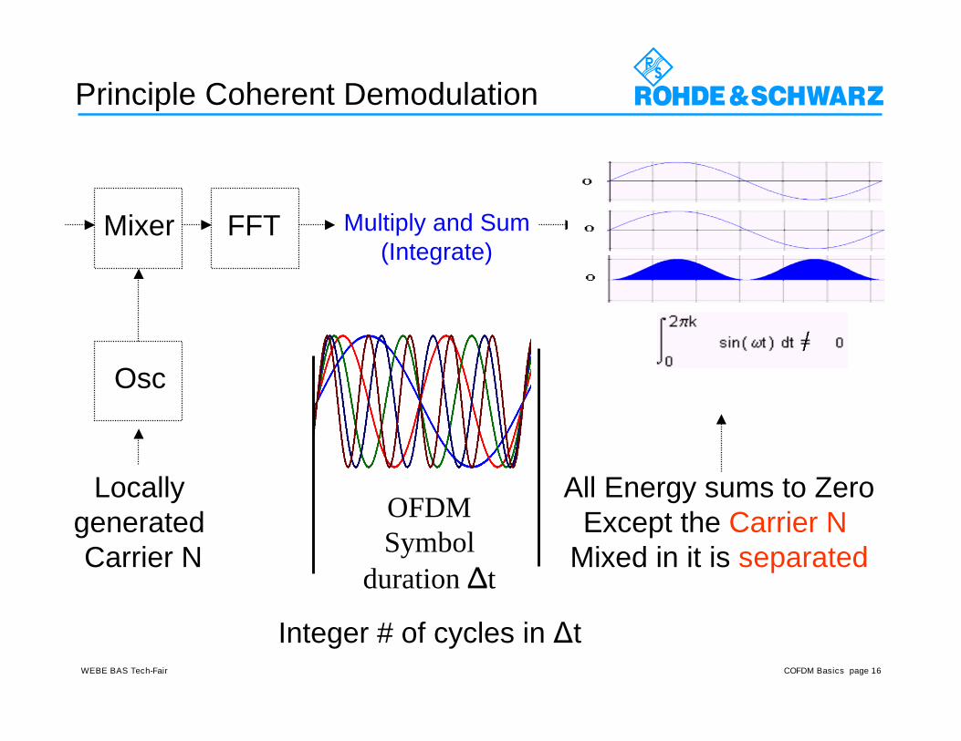
Principle Coherent Demodulation
FFT Multiply and Sum(Integrate)
All Energy sums to Zero
Integer # of cycles in Δt
COFDM Basics page 16WEBE BAS Tech-Fair
OFDMSymbol
duration Δt
Principle Coherent Demodulation
FFT Multiply and Sum(Integrate)
All Energy sums to ZeroExcept the Carrier N
Mixed in it is separated
Integer # of cycles in Δt
Mixer
Locally generated Carrier N
Osc

COFDM Basics page 17WEBE BAS Tech-Fair
Coherent Demodulation Process 1. Receiver Synchronization ( Time & Frequency)
MPEG2-TSRF
IF
A
D
Dig.IQ Mixer
FFT Synchr.ChannelEstim. &Correction
Demapping&FEC
DVB-T Receiver : simplified Block Diagram
Frequency FFTWindow
2. Perform FFT (Convert to Freq Domain), Locally generate a carrier equal in frequency & phase to the
first carrier, mix with received COFDM symbol Integrate over the period Tu The first carrier will be shifted vertically (beat down zero dc) and hence separated, Modulation recovered, Other carriers Integrate to Zero 3. Very rapidly repeat step two above (1704
times 2K mode) for each carrier frequency in turnuntil all carriers have been effectively separated
(Tu)

COFDM Basics page 18WEBE BAS Tech-Fair
Example: DVB-T 2K (6MHz)
Useful Bandwidth (BW) = 5.705357 MHzNumber Carriers (K) = 1,705Symbol Duration (Tu) = (K-1)/BW = 298.667 uSCarrier Spacing (Hz) = 1/Tu = 3,348.214 Hz
(Tu)

COFDM Basics page 19WEBE BAS Tech-Fair
Modulation
f
Channel bandwidthΔf

COFDM Basics page 20WEBE BAS Tech-Fair
Mapping Bits into Symbols
X
XMap
per
+
X
XMap
per
+
..... OFDM
SymbolΣBits

COFDM Basics page 21WEBE BAS Tech-Fair
Digital Modulation of a Single Carrier
+
90
Mapperdata(t)
i(t)
q(t)
iqmod(t)
lo(t)
I
Q
I
Q
+/-1
QPSK
+/-1

COFDM Basics page 22WEBE BAS Tech-Fair
Digital Modulation of a Single Carrier
data(t)
i(t)
q(t)
Constellation
time
0 0 0 0 01 1 1 1 1
-1 -1
-1 -1+1
+1 +1
+1 +1
-1
Symbol
Time
Symbol Rate = 1 / Symbol TimeNeeded Bandwidth = Symbol Rate
+
90
Mapperdata(t)
i(t)
q(t)
iqmod(t)
lo(t)
I
Q +/-1
+/-1
Bit 1 Bit 0 I Q
0 0 +1 +1
0 1 -1 +1
1 0 -1 -1
1 1 +1 -1
Mapping Table
IQ
QPSK0001
10 11
+1
+1
ffLO
Spectrum
BW

COFDM Basics page 23WEBE BAS Tech-Fair
QPSK, 16QAM, 64QAM
QPSK = 4QAM2 Bit / Symbol
16QAM4 Bit / Symbol
64QAM6 Bit / Symbol
DVB-T Constellations

COFDM Basics page 24WEBE BAS Tech-Fair
Maintaining Orthogonality
• How to Handle Multi-path Environment– Use a Long Symbol Period w/ respect to
speed of light (RF Propagation)
– Insert Guard Interval (GI)
– GI Mitigates Inter-Symbol Interference (ISI)
• A contrasting comparison is given– Single vs. Multiple Carrier System

COFDM Basics page 25WEBE BAS Tech-Fair
Additive WhiteGaussian Noise(AWGN): Whenthere is only asingle RF path tothe receiver, thesystem can beviewed asoperating over anAWGN channel
Rician Fading Channel: Consists of adirect RF path and one or more indirectpaths that may be static or dynamic in
nature. Most urban and indoor receptionenvironments qualify.
Rayleigh FadingChannel: Whenthere is no direct RFpath to the receiver,only echoes (staticor time varying) arereceived. Applies tourban outdoor andall indoor sites whenno direct RF path tothe receiver exists.Also, a portable ormobile receiver ifused, would mostlikely exhibitRayleighian channelcharacteristics.
Propagation Models

COFDM Basics page 26WEBE BAS Tech-Fair
Comparison Symbol Period (6 MHz)
~ 1/60 Symbol ElapseDVB-T 8K~ 1/15 Symbol ElapseDVB-T 2K
~ 215 Symbols ElapseATSC 8-VSB
Echo Delay = 20usecSYSTEM
~ 1195 usecDVB-T 8K~ 299 usecDVB-T 2K~ 93 nsecATSC 8-VSB
Symbol PeriodSYSTEM
DVB-T 2K ~ 3215 x ATSCDVB-T 8K ~ 12,860 x ATSC
Example: Echo Delay = 20usec

COFDM Basics page 27WEBE BAS Tech-Fair
Intersymbol Interference (ISI)
Symboln+5
Symboln+2
Symboln+3
Symboln+4
Symboln
Symboln+1
Symboln+5
Symboln+2
Symboln+3
Symboln+4
Symboln
Symboln+1
Δt
Δt = Echo delay time
Intersymbol interference
+
=
Path1
Path2
Path1+2
Only beginning portion of Symbol
ISI

COFDM Basics page 28WEBE BAS Tech-Fair
freq
time
OFDM SYMBOL
Useful Part(Tu)
Guard Interval Δ
Bandwidth
Carrier Spacing
Δ n
OFDM Symbol + Guard Δ
ΔΔΔ
Δ
SymbolBegin
SymbolEnd
Correlation Technique used at receiver• Identify FFT Size• Identify Guard Value
TRANSMITTER
RECEIVER

COFDM Basics page 29WEBE BAS Tech-Fair
n-2
n-1 Symbol n n+1
Receiver Synchronization Window
f
t
Δ n-1 Δ n Δ n+1
Δ n-1 Δ n Δ n+1
Main PathSignal
Echo Path
Echo Delay < Guard Interval
FFT FFT FFT
OKIntra-Symbol Interference

COFDM Basics page 30WEBE BAS Tech-Fair
Echo Delay > Guard Interval
n-1 n+1
f
t
Delay> Δ
Δ n-1 Δ n Δ n+1
No Synchronization of the Receiver !
Symbol n
Main PathSignal
Echo Path n-1 Δ n Δn-2 Δ
FFT FFT FFT
Bad !Inter-Symbol
Interference (ISI)

COFDM Basics page 31WEBE BAS Tech-Fair
DVB-T Transmitter Block
FEC LPSymbol
Inter-
leaver
Frame
Adapt.IFFT
Guard
Interv.
Insert.
Pre-
Corr.
FIR
Filter
FEC HP
(Option)
Dem
ux
Bit
Inter-
leaver
Band-
Pass
Filter
IF
RF
Map
per
Power
Ampl.
TS1
TS2
Pilots, TPS
C(oded) O(rthogonal) F(requency) D(ivision) M(ultiplex)
(2, 4, 6)
Freq Domain Time Domain
OFDMCoding

COFDM Basics page 32WEBE BAS Tech-Fair
COFDM DSP (IFFT)
IFFT
Time domain
time
u(t)
N points
ts
T
re(t)
im(t)
Frequency domain
f
Re(f)
f
Im(f)
N points
fs = 1/ts
N points
Äf=fs/N
Re(f)
Im(f)

COFDM Basics page 33WEBE BAS Tech-Fair
IFFT
+
90
IFFT
Re(f)
Im(f)
re(t)
im(t)
ofdm(t)
lo(t)
I
Q

COFDM Basics page 34WEBE BAS Tech-Fair
Symbol / No GI
Re(f)
Im(f)
re(t)
im(t)ofdm(t)
Frequencydomain
Timedomain

COFDM Basics page 35WEBE BAS Tech-Fair
Symbols /w Guard Interval (GI)
Symbol n Symbol n+1Guard intervalNote: Can’t be Blank
This will destroy Orthogonality

COFDM Basics page 36WEBE BAS Tech-Fair
Symbol n+1Symbol nGuard Interval
Symbols /w Guard Interval (GI)
Note: Cyclic ExtensionPreserves Orthogonality

COFDM Basics page 37WEBE BAS Tech-Fair
Processing of Guard Interval
IFFT
MEM1
MEM2
Pointer
Read FirstRead Next
Pointer
GI
TuSymbol

COFDM Basics page 38WEBE BAS Tech-Fair
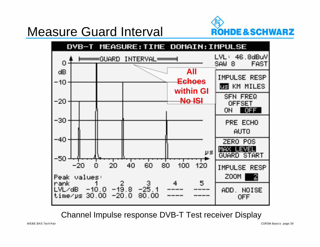
Channel Impulse Response
Receiver Positions FFT Window
COFDM Basics page 39WEBE BAS Tech-Fair
Measure Guard Interval
Channel Impulse response DVB-T Test receiver Display
AllEchoes
within GINo ISI

COFDM Basics page 40WEBE BAS Tech-Fair
Special Carriers in DVB-T
Continual orScattered
pilot
Continual orScattered
pilot
TPSCarrier
TPSCarrier

COFDM Basics page 41WEBE BAS Tech-Fair
Pilots inside constellation diagram
Q
I
64 QAM not hierarchical
! = 1
continous and scattered pilots
TPS Carrier
Data Carrier

COFDM Basics page 42WEBE BAS Tech-Fair
Special pilot Carriers in DVB-T
Continual pilots- fixed position in spectrum- fixed postion in constellation diagram- used for automatic frequency control (AFC)Scattered pilots- var. position in spectrum- fixed position in constellation diagram- „sweeping“ over spectrum- used for channel estimation & correctionTPS carrier- fixed position in spectrum- BPSK modulation- transmission parameter signalling (TPS)- fast information channel from Tx to Rx

COFDM Basics page 43WEBE BAS Tech-Fair
Pilots inside 6 MHz Channel
Scattered Pilots
Continuous Pilots
TPS Pilots
Channel BW

COFDM Basics page 44WEBE BAS Tech-Fair
Scattered Pilots
t
fFreq
Time
FFT
Gua
rd Δ
Tu
Scattered Pilots Boosted 2.5 dB“Used by Receiver to Estimate Channel”

COFDM Basics page 45WEBE BAS Tech-Fair
Channel Estimation using Pilots
FC
f
Hn,k
4 Symbols
ΔFp=Tu/3
INTERPOLATION OF THE CHANNEL RESPONSE
Scattered pilots

COFDM Basics page 46WEBE BAS Tech-Fair
EQUALIZATION
CORRECTED SIGNAL
ESTIMATION OF THECHANNEL
RECEIVED SIGNAL
Freq Domain Equalization

COFDM Basics page 47WEBE BAS Tech-Fair
DVB-T Transmitter (FEC)
Base-
band
Interf.
Sync
Invers.
Energy
Disp.
Reed-
Solom.
Enc.
Conv.
Inter-
leaver
Conv.
Coder
Pu
nct
uri
ng
Synchronization
Inv. Sync.
TS In
same as DVB-C
same as DVB-S
Code Rate
1/2...(3/4)...7/8
FEC1/
Outer
Coder
FEC2/
Inner
Coder
Data Rate In
= Date Rate Out
[2.17...(1.63)...1.36]
x 204/188 x 2 x (1.5-Code Rate)
Coded
Data
Out

COFDM Basics page 48WEBE BAS Tech-Fair
INNER CONVOLUTIONAL CODING
CONVOLUTIONALENCODER
XDATA
1 Bit IN
The Convolutional Code is used over a noisy channel
The basic code rate is ½ (called the Mother Code)
The encoder is very simple to implement
But the decoding is quite complex !
The Viterbi algorithm is currently used for decoding
Punctured coding techniques can be applied to allow higher bit rates
Tradeoff Robustness vs. DataRate 1/2, 2/3, 3/4, 5/6, 7/8 coding rates available
Y
2 Bits Out

COFDM Basics page 49WEBE BAS Tech-Fair
PUNCTURING The Mother Code
CONVOLUTIONALENCODER
RATE 1/2RATE 3/4
PUNCTURECOMMUNICATION
CHANNELNULL-BIT
INSERTIONRATE 1/2
VITERBIDECODER
DATAINPUT
ENCODEDDATA
PUNCTUREDENCODED DATA Rx DATA WITH
NULL INSERTIONSDATA
OUTPUT
D1 D2 D3 D4 D5 D6
X1 X2 X3 X4 X5 X6
Y1 Y2 Y3 Y4 Y5 Y6
X1 Y1 Y2 X3 X4 Y4 Y5 X6
RX1 RX3 RX4 RX6
RY1 RY2 RY4 RY5 ∅ ∅ ∅
∅
D1 D2 D3 D4 D5 D6
DATA INPUT
ENCODED DATA
PUNCTURED DATA
RECEIVED DATAW/ NULL INSERTIONS
DECODED DATA
RATE = 1/2
RATE = 3/4
1 2 3
1 2 3 4
X2
Y3
X5
Y6
PUNCTURE DATA

COFDM Basics page 50WEBE BAS Tech-Fair
Interleaving (Frequency Diversity) Fr
eque
ncy I
nter
leavi
ng
Time
time
freq
Input Data
Coded Data
Create frequency diversity to improve robustness against fadingCreate frequency diversity to improve robustness against fading

COFDM Basics page 51WEBE BAS Tech-Fair
DVB-T Receiver
IF
RF SAWfilter(BP)
LO
Lowpassfilter D
AFFT
De-
map
per
FIR
Delay
90
NCO
Cha
nnel
corr
ect.
Cha
nnel
deco
der
Timesync.
Chan.estim
Freqcorr.
TPSdec.
TS
Clock
fs = 32/7 MHz(if2 = fs/4)
FFT Window
Scatt.pilots
Cont.pilots
TPScarr.
Analog frontend

COFDM Basics page 52WEBE BAS Tech-Fair
0
1
LogicalState
t
TRANSMITTED BITS0
LogicalState
t
RECEIVED BITS
Strongest 1111110101100011010001000
Weakest 1Weakest 0
Strongest 00
10 00
0111
LP0,LP1
LP1
LP0
Using Channel State Info
NoisyCOMMUNICATION
CHANNEL
Receiver Technique

COFDM Basics page 53WEBE BAS Tech-Fair
Channel State Information (CSI)
• Some carrier frequencies will be experiencing a low SNR (in a spectralnotch), while others will actually be boosted in power
• CSI metric is generated in the receiver for each and every received carrier,and is used to aid the Error Correction process
• Generated at receiver based on SNR of each carrier– If SNR Good = Equalize as normal
– If SNR Lower = Use CSI
– If SNR Bad = Insert Null bit ( as in Puncture Coding)
ViterbiDecoder
Inserting Null Bit = Zero Confidence
0 0 0 0 0 0 0

COFDM Basics page 54WEBE BAS Tech-Fair
DVB-T Frame Review
2k FFT 8k FFT
Data Carriers: 1705 6817
Scattered Pilots: 142 568
Continual Pilots: 45 177
Cont. TPS Pilots: 17 68
1.) Scattered pilots are used for channel estimation andcorrection
2.) Continual pilots are used for time and frequencysynchronization
3.) TPS pilots carry COFDM parameter information

COFDM Basics page 55WEBE BAS Tech-Fair
DVB-T Features & Parameters
COFDM Encoding and Modulation• Robustness against multipath propagation
• Single Frequency Network capability
• Mobile reception
DVB-T Standard ETSI EN 300 744• 6, 7 , 8 MHz
• 2K and 8K carriers OFDM
• 1/4, 1/8, 1/16, 1/32 guard intervals (multipath - «echo»protection)
• 4 QAM, 16 QAM, 64 QAM modulation
• 1/2, 2/3, 3/4, 5/6, 7/8 coding rates (error correction)
• Hierarchical modulation option

COFDM Basics page 56WEBE BAS Tech-Fair
Which COFDM Parameters to use ?
COFDM Basics page 57WEBE BAS Tech-Fair
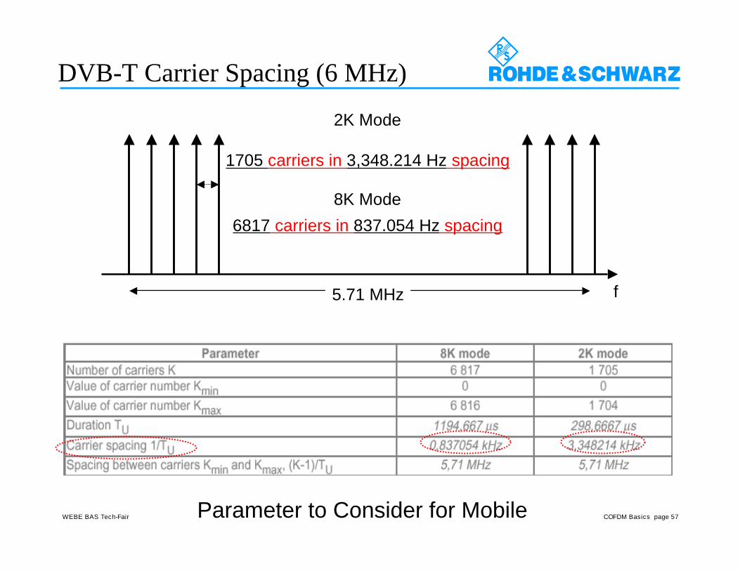
DVB-T Carrier Spacing (6 MHz)
5.71 MHz
8K Mode6817 carriers in 837.054 Hz spacing
f
2K Mode
1705 carriers in 3,348.214 Hz spacing
Parameter to Consider for Mobile