COEN 180 Hard Drive Interface Evolution. Hard Drive Interface How does the system interact with the...
33
COEN 180 Hard Drive Interface Evolution
-
Upload
horace-pitts -
Category
Documents
-
view
216 -
download
3
Transcript of COEN 180 Hard Drive Interface Evolution. Hard Drive Interface How does the system interact with the...
COEN 180
Hard Drive Interface Evolution
Hard Drive Interface Evolution
Hard Drive Interface How does the system interact with
the disk. Slow development towards
autonomous, intelligent storage devices.
Hard Drive Interface Evolution ST412/506
Named after two Seagate disks from 1980 and 1981.
Adopted by IBM for PC Hard drive accommodates only
control circuitry for stabilizing disk rotation and head position.
Everything else is controlled by the controller.
Hard Drive Interface Evolution
Disk interface resides in adapter card.
Connected with two cables 20 pin data or B cable. 34 pin controller or A cable.

Hard Drive Interface Evolution ST412/506
Write operation (as an example) Controller knows the current track. Uses the direction signal and the step signal to
move one track at a time. If the controller ever looses control of the track,
then the controller moves the heads outwards until the drive indicates with the track 00 signal that the head is over the outmost track.
Sector identification is in the sector header. Once correct sector is reached, controller sends
over the write current. Any type of magnetic code can be used.
MFM gives a data rate of 5MHz RLL 7,2 gives a data rate of 7.5MHz.

Hard Drive Interface Evolution
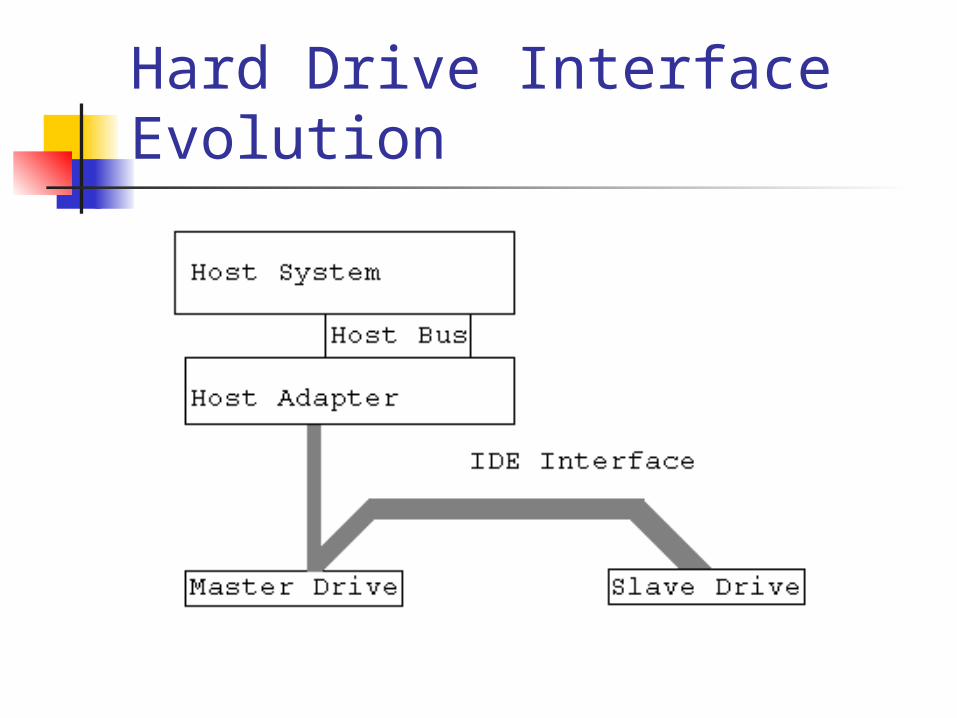
IDE 1984: Compaq asked Western Digital
to produce an ST506 controller embedded in the hard drive itself and connected to the system bus via a 40 pin cable.
IDE is standardized as the ATA standard.
Hard Drive Interface Evolution
Hard Drive Interface Evolution
IDE implements a register model. To the host system, the IDE controller
looks like two blocks of I/O registers in the I/O space of the ISA bus.
Registers allow the host To control hard drive, To control transfer rate (via PIO or DMA). To receive status messages.

Hard Drive Interface Evolution
IDE PIO command Sets up a register block
Writes IDE address register Writes Drive / Head register
Which contains bits for the head number. Writes sector count register. Writes feature register. Etc.
Hard Drive Interface Evolution IDE PIO command
Sets up a register block Sends the write command to disk. Drive responds by setting DRIVE READY bit in the status
register. Host writes data via the data register to the sector
buffer. When the sector buffer is full, then the disk drive sets
the BUSY bit in the status register. Data is written to the medium. Drive deasserts the BUSY bit and sets the INTRQ bit. That signals the host to read the status register. Status register (hopefully) indicates a successful write.
Hard Drive Interface Evolution
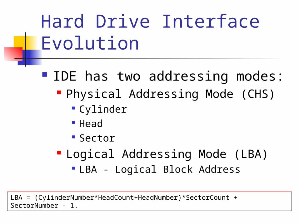
IDE has two addressing modes: Physical Addressing Mode (CHS)
Cylinder Head Sector
Logical Addressing Mode (LBA) LBA - Logical Block Address
LBA = (CylinderNumber*HeadCount+HeadNumber)*SectorCount + SectorNumber - 1.
Hard Drive Interface Evolution
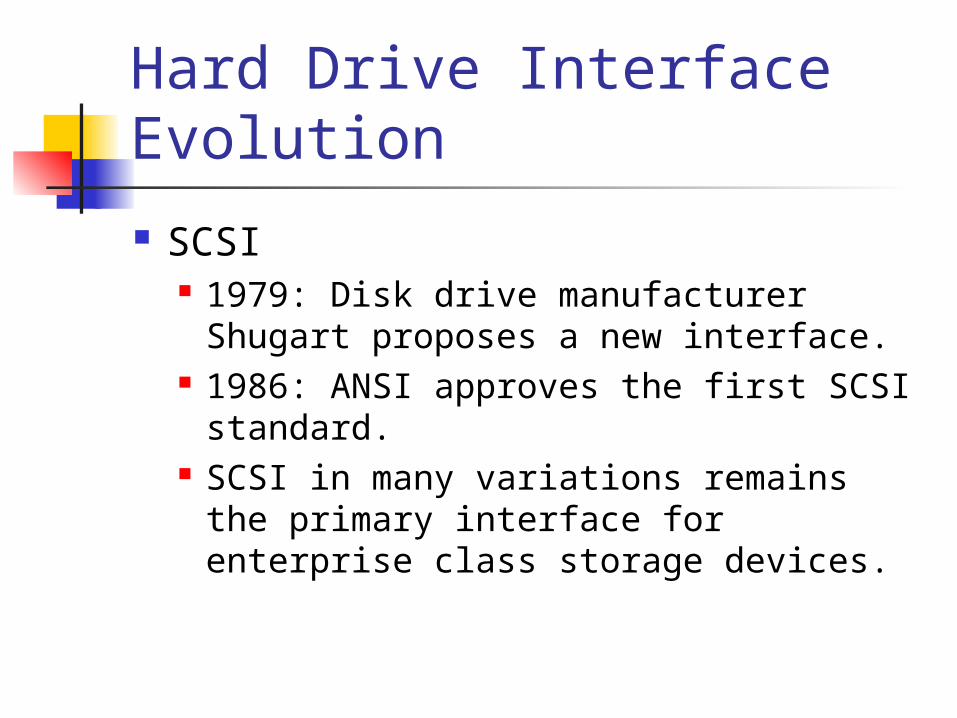
SCSI 1979: Disk drive manufacturer
Shugart proposes a new interface. 1986: ANSI approves the first SCSI
standard. SCSI in many variations remains the
primary interface for enterprise class storage devices.
Hard Drive Interface Evolution
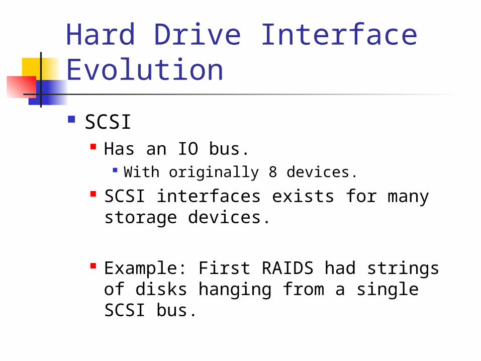
SCSI Has an IO bus.
With originally 8 devices. SCSI interfaces exists for many
storage devices.
Example: First RAIDS had strings of disks hanging from a single SCSI bus.
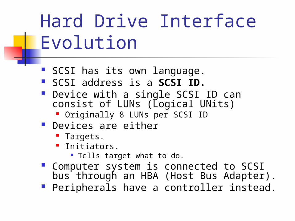
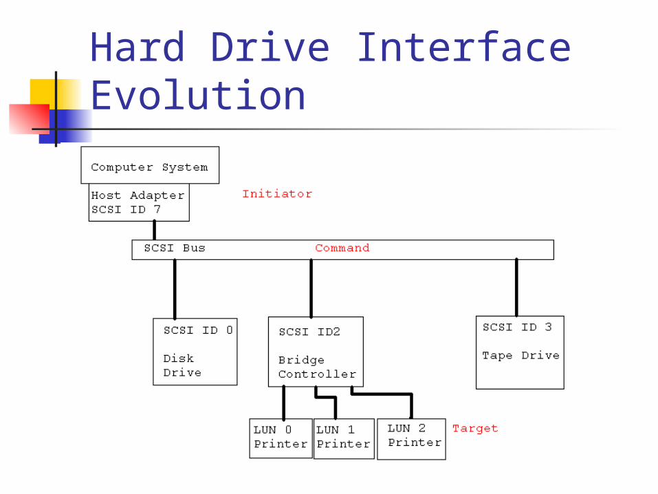
Hard Drive Interface Evolution SCSI has its own language. SCSI address is a SCSI ID. Device with a single SCSI ID can consist of
LUNs (Logical UNits) Originally 8 LUNs per SCSI ID
Devices are either Targets. Initiators.
Tells target what to do. Computer system is connected to SCSI bus
through an HBA (Host Bus Adapter). Peripherals have a controller instead.
Hard Drive Interface Evolution
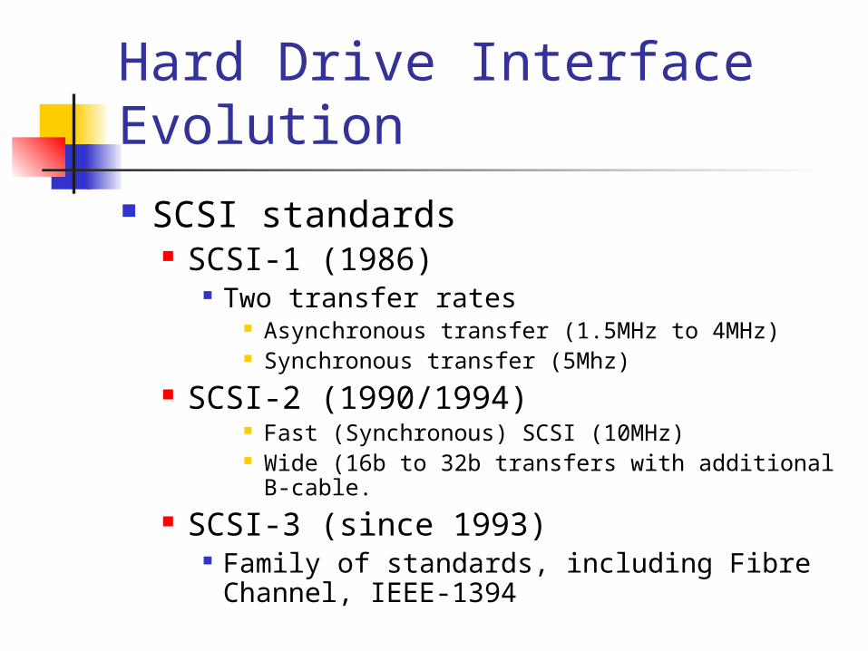
Hard Drive Interface Evolution SCSI standards
SCSI-1 (1986) Two transfer rates
Asynchronous transfer (1.5MHz to 4MHz) Synchronous transfer (5Mhz)
SCSI-2 (1990/1994) Fast (Synchronous) SCSI (10MHz) Wide (16b to 32b transfers with additional B-
cable. SCSI-3 (since 1993)
Family of standards, including Fibre Channel, IEEE-1394
Hard Drive Interface Evolution
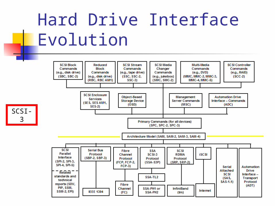
SCSI-3
Hard Drive Interface Evolution
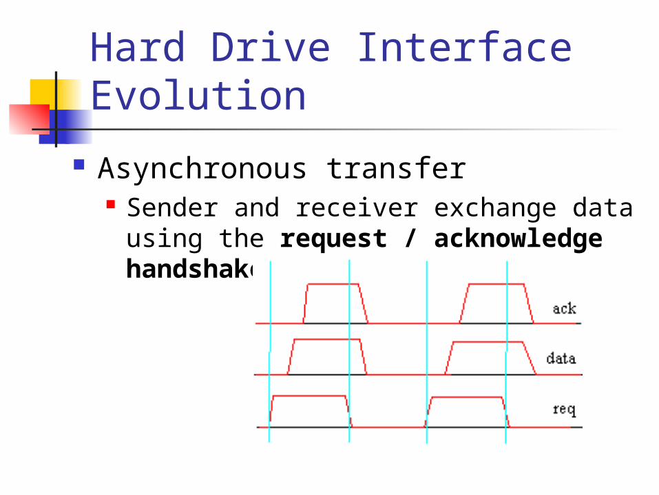
Asynchronous transfer Sender and receiver exchange data
using the request / acknowledge handshake.
Hard Drive Interface Evolution
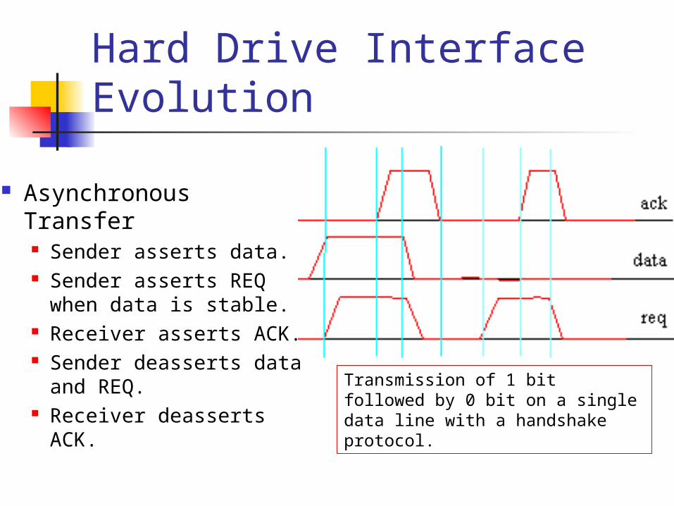
Asynchronous Transfer Sender asserts data. Sender asserts REQ
when data is stable. Receiver asserts ACK. Sender deasserts
data and REQ. Receiver deasserts
ACK.
Transmission of 1 bit followed by 0 bit on a single data line with a handshake protocol.
Hard Drive Interface Evolution
Synchronous Transfer Sender and Receiver negotiate a
clock rate at which data is send.
Hard Drive Interface Evolution
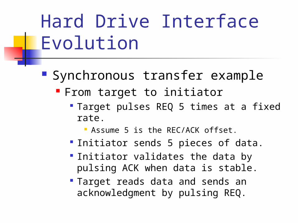
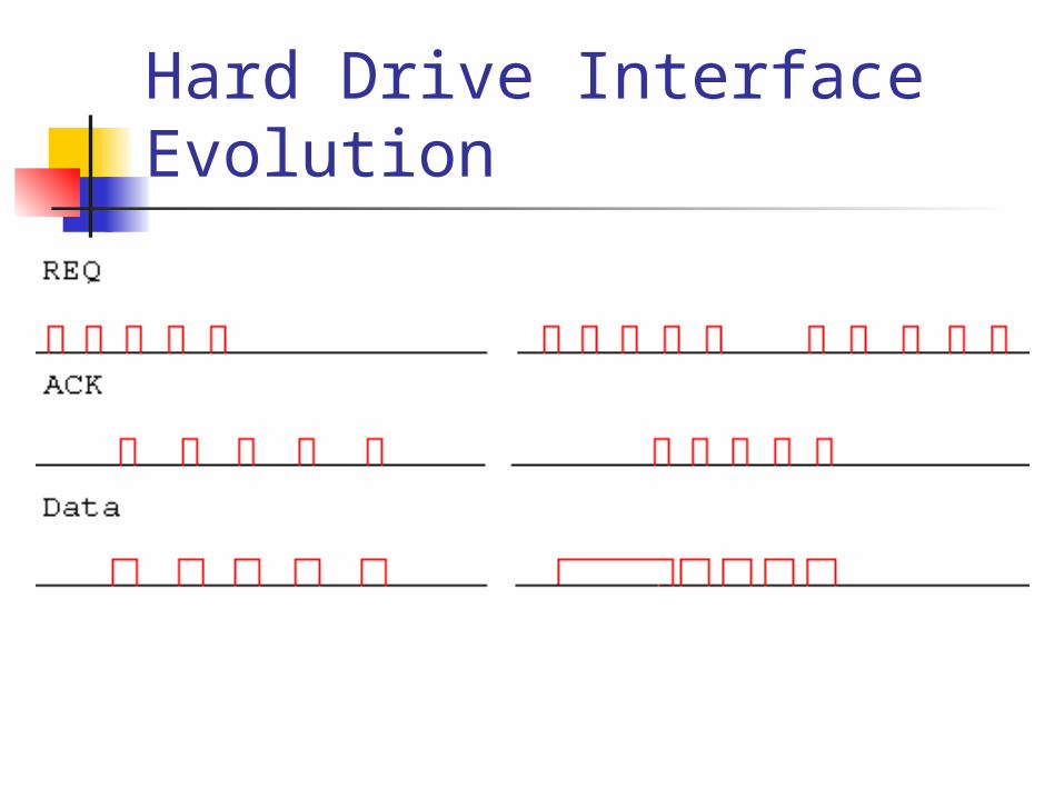
Synchronous transfer example From target to initiator
Target pulses REQ 5 times at a fixed rate. Assume 5 is the REC/ACK offset.
Initiator sends 5 pieces of data. Initiator validates the data by pulsing ACK
when data is stable. Target reads data and sends an
acknowledgment by pulsing REQ.
Hard Drive Interface Evolution
Hard Drive Interface Evolution
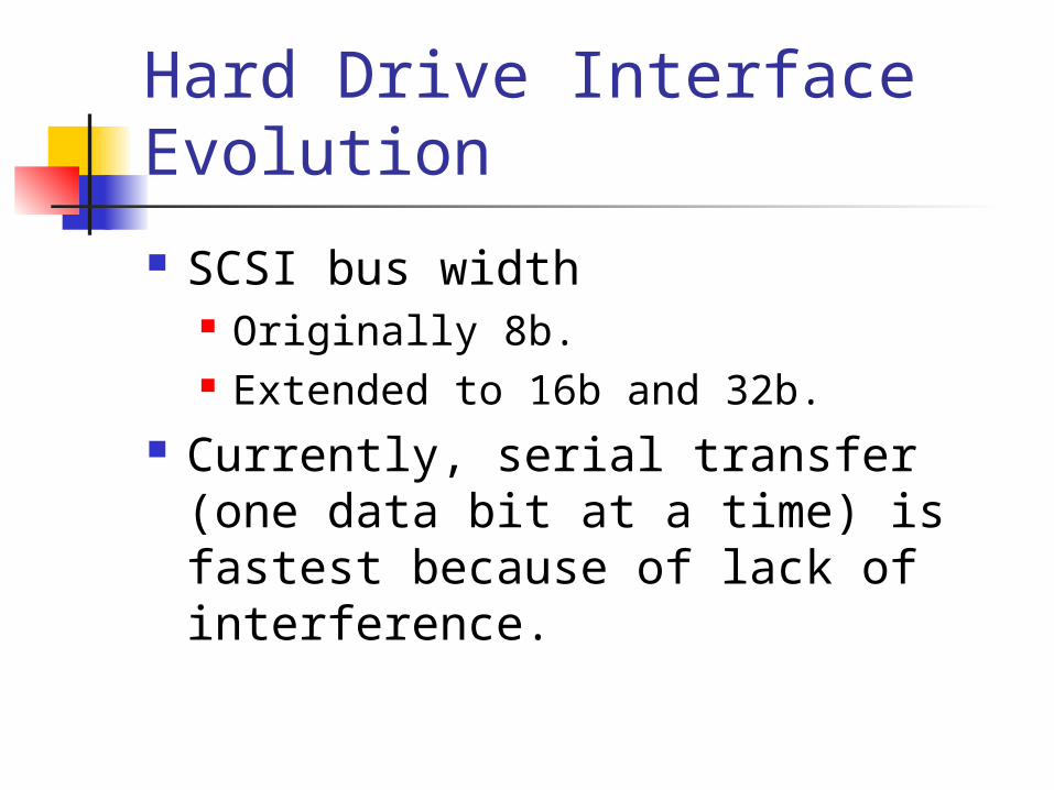
SCSI bus width Originally 8b. Extended to 16b and 32b.
Currently, serial transfer (one data bit at a time) is fastest because of lack of interference.
Hard Drive Interface Evolution
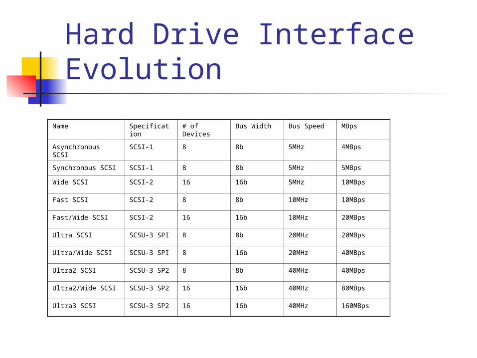
Name Specification # of Devices Bus Width Bus Speed MBps
Asynchronous SCSI SCSI-1 8 8b 5MHz 4MBps
Synchronous SCSI SCSI-1 8 8b 5MHz 5MBps
Wide SCSI SCSI-2 16 16b 5MHz 10MBps
Fast SCSI SCSI-2 8 8b 10MHz 10MBps
Fast/Wide SCSI SCSI-2 16 16b 10MHz 20MBps
Ultra SCSI SCSU-3 SPI 8 8b 20MHz 20MBps
Ultra/Wide SCSI SCSU-3 SPI 8 16b 20MHz 40MBps
Ultra2 SCSI SCSU-3 SP2 8 8b 40MHz 40MBps
Ultra2/Wide SCSI SCSU-3 SP2 16 16b 40MHz 80MBps
Ultra3 SCSI SCSU-3 SP2 16 16b 40MHz 160MBps
Hard Drive Interface Evolution
HBA Gives system access to a SCSI bus System can have many HBAs.
Storage Area Network: Addresses
Bus Target LUN
Hard Drive Interface Evolution Devices are either initiator or target.
Originally, a device was either one or the other.
Now, they can be both. Example:
Tape drive is target when the system sends it a command.
When the tape is ready to perform the command, it might become the initiator and the system the target.
Hard Drive Interface Evolution
The initiator is the master in the function and the slave in protocol, the target is the slave in function and the master in protocol" (M. Schultz).
Hard Drive Interface Evolution
SCSI cables A cable has 50 pin B cable has 68 pins in SCSI 1.
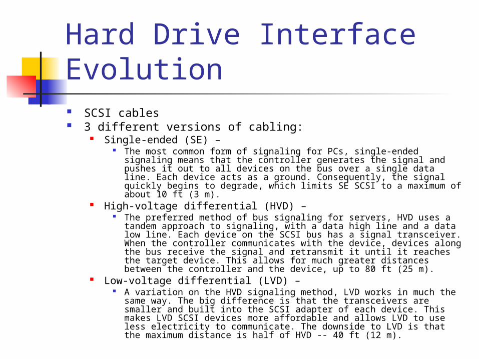
Hard Drive Interface Evolution SCSI cables 3 different versions of cabling:
Single-ended (SE) – The most common form of signaling for PCs, single-ended signaling
means that the controller generates the signal and pushes it out to all devices on the bus over a single data line. Each device acts as a ground. Consequently, the signal quickly begins to degrade, which limits SE SCSI to a maximum of about 10 ft (3 m).
High-voltage differential (HVD) – The preferred method of bus signaling for servers, HVD uses a tandem
approach to signaling, with a data high line and a data low line. Each device on the SCSI bus has a signal transceiver. When the controller communicates with the device, devices along the bus receive the signal and retransmit it until it reaches the target device. This allows for much greater distances between the controller and the device, up to 80 ft (25 m).
Low-voltage differential (LVD) – A variation on the HVD signaling method, LVD works in much the same
way. The big difference is that the transceivers are smaller and built into the SCSI adapter of each device. This makes LVD SCSI devices more affordable and allows LVD to use less electricity to communicate. The downside to LVD is that the maximum distance is half of HVD -- 40 ft (12 m).
Hard Drive Interface Evolution
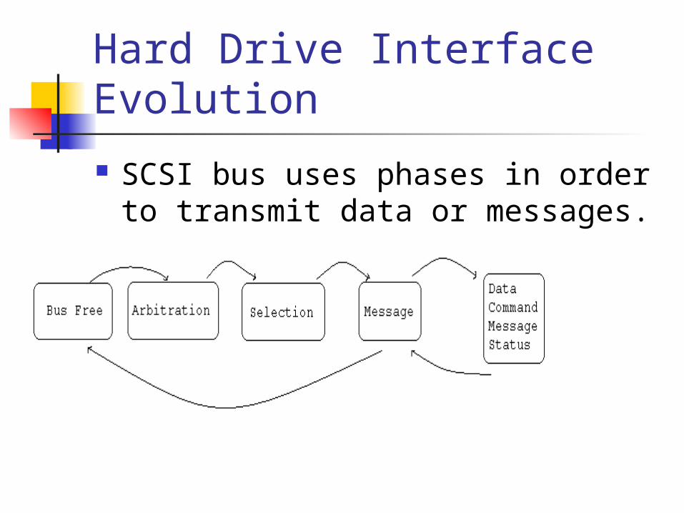
SCSI bus uses phases in order to transmit data or messages.
Hard Drive Interface Evolution Bus free phase. Arbitration phase
one or more initiators indicate that they would like to use the bus.
If more than one initiator enters the arbitration phase, the one with the highest SCSI ID wins.
Selection phase, Initiator puts the address of the target onto the data
bus. (The reselection phase fulfills a similar function, after
winning arbitration, a target that released the bus to execute a command can reestablish the connection to the initiator.)
Hard Drive Interface Evolution Four phases for exchanging data:
command phase is used for transferring command opcodes,
data phase is used for transferring data bytes,
message phase allows sending or receiving information concerning the protocol itself,
status phase concludes a command and gives the status of the operation back to the initiator.
Hard Drive Interface Evolution
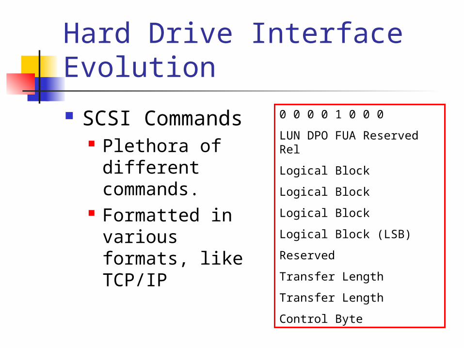
SCSI Commands Plethora of
different commands.
Formatted in various formats, like TCP/IP
0 0 0 0 1 0 0 0
LUN DPO FUA Reserved Rel
Logical Block
Logical Block
Logical Block
Logical Block (LSB)
Reserved
Transfer Length
Transfer Length
Control Byte