COE Maximizing CATIA Performance for Large Assemblies · PDF fileMaximizing CATIA Performance...
39
Product Lifecycle Management © 2007 IBM Corporation Maximizing CATIA Performance for Large Assemblies Rich Healy IBM PLM
Transcript of COE Maximizing CATIA Performance for Large Assemblies · PDF fileMaximizing CATIA Performance...

Product Lifecycle Management
© 2007 IBM Corporation
Maximizing CATIA Performance for Large Assemblies
Rich HealyIBM PLM

Product Lifecycle Management
© 2007 IBM Corporation
Agenda
� Large Assembly basics
� Settings to improve graphics performance
� Settings to work efficiently with Large Assemblies
� Other Operational tips
� Hardware and O/S considerations

Product Lifecycle Management
© 2007 IBM Corporation
Large Assembly Basics
What characterizes a “Large Assembly”?1. High number of small parts (fasteners, clips, std parts)
2. Collection of very complex (“heavy”) parts
3. Assembly that is dimensionally large
4. Assembly that is very dense
Aerospace assemblies are often some combination of all.
All present challenges to working efficiently and can frustrate users if performance is not adequate.

Product Lifecycle Management
© 2007 IBM Corporation
Large Assembly Basics (2)
How do I maximize my productivity when working with Large Assemblies?
1. Use the appropriate settings to “tune” your system for best performance
2. Employ working practices and techniques that contribute to system efficiency
• Load and visualize only what you need• Structure you data properly
• Learn (and use) the tools and techniques
3. Utilize the latest hardware platforms

Product Lifecycle Management
© 2007 IBM Corporation
Use Settings to “tune” your system
� Settings to optimize graphics performance
– Time do display the geometry
– Responsiveness and Smoothness when moving geometry on screen
– Time to select or highlight geometry
� Settings to improve interactive performance
– Minimize the amount of data loaded into memory
– Improve loading time

Product Lifecycle Management
© 2007 IBM Corporation
Settings to enhance graphics performance
Tools└ Options└ General└ Display – Visualization tab
Uncheck - Graduated color background (checked by default)
Uncheck - Anti-aliasing

Product Lifecycle Management
© 2007 IBM Corporation
Settings to enhance graphics performance
Tools└ Options└ General└ Display – Navigation tab
Uncheck - Preselect Geometry in view (checked by default)*
* Note: This may disable the “Other Selection...” option from the contextual menu (R18)

Product Lifecycle Management
© 2007 IBM Corporation
Settings to enhance graphics performance
Tools└ Options└ General└ Display – Performance tab
Check - Occlusion culling enabled (default is unchecked)*
* Occlusion culling is multi-threaded so will take advantage of multi-processor or multi-core systems
Product Lifecycle Management
© 2007 IBM Corporation
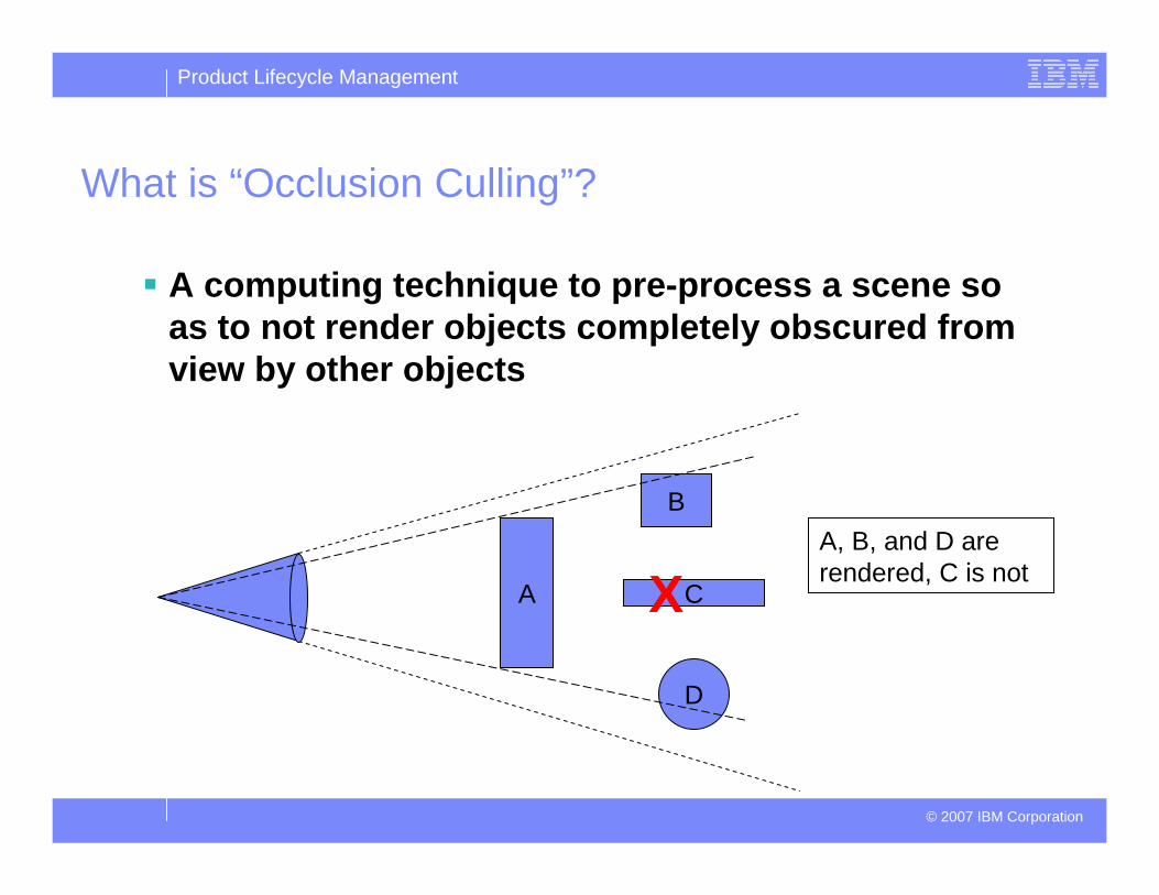
What is “Occlusion Culling”?
� A computing technique to pre-process a scene so as to not render objects completely obscured from view by other objects
A
B
D
CXA, B, and D are rendered, C is not

Product Lifecycle Management
© 2007 IBM Corporation
Settings to enhance graphics performance
Tools└ Options└ General└ Display – Performance tab
Set 3D Accuracy to “Proportional”Suggested value = 0.5(default is “Fixed” with a 0.20 value)
Especially significant for dimensionally large surfaces
Can use triangle visualization or triangle count command to quantify

Product Lifecycle Management
© 2007 IBM Corporation
Demonstration of 3D accuracy setting for dimensionally large surfaces
222,626Triangles
Usingdefault
Accuracy:Fixed=0.2
8,435Triangles
UsingsuggestedAccuracy:
Proportional=0.5
Hard to “see”difference with
shading
Difference is obvious with
triangles display
Fixed Proportional

Product Lifecycle Management
© 2007 IBM Corporation
Settings to enhance graphics performance
Tools└ Options└ General└ Display – Performance tab
Set Curves’ accuracy ratio to 1.00(this is the default value)
Value of 1.00 means surface boundary curves have same accuracy as surface interior
Smaller value = greater precision
Reducing the value tightens mesh at surface boundaries

Product Lifecycle Management
© 2007 IBM Corporation
Greater accuracy
along surface
boundary
Demonstration of curves’ accuracy ratio setting
Curves’ accuracy ratio =1.00 Curves’ accuracy ratio = 0.10

Product Lifecycle Management
© 2007 IBM Corporation
Settings to enhance graphics performance
Tools└ Options└ General└ Display – Performance tab
Set 2D Accuracy to “Proportional”Suggested value = 0.1(default is “Fixed” with a 0.20 value)
Same concept as 3D Accuracy except for 2D applications like drafting, sketcher, 2D Layout for 3D Design

Product Lifecycle Management
© 2007 IBM Corporation
Settings to enhance graphics performance
Tools└ Options└ General└ Display – Performance tab
Set Level of DetailStatic = 5 (default = 0.5)While Moving = 10 (default = 3)
Valid only in visualization mode
Need to check “Save level of details in cgr” underTools└ Options└ Infrastructure└ Product Structure – Cgr Management tab

Product Lifecycle Management
© 2007 IBM Corporation
Demonstration of Level of Detail Settings
Low “Static” value displays good shape fidelity when view is stationary
Higher “While moving”value displays simplified shapes when moving the view

Product Lifecycle Management
© 2007 IBM Corporation
Settings to enhance graphics performance
Tools└ Options└ General└ Display – Performance tab
Set Pixel CullingStatic = 5 (default = 0.5)*
While Moving = 10 (default = 3)
* Values of 5 and above will not display points. If you need to see points, set value at 4 (or below).
Product Lifecycle Management
© 2007 IBM Corporation
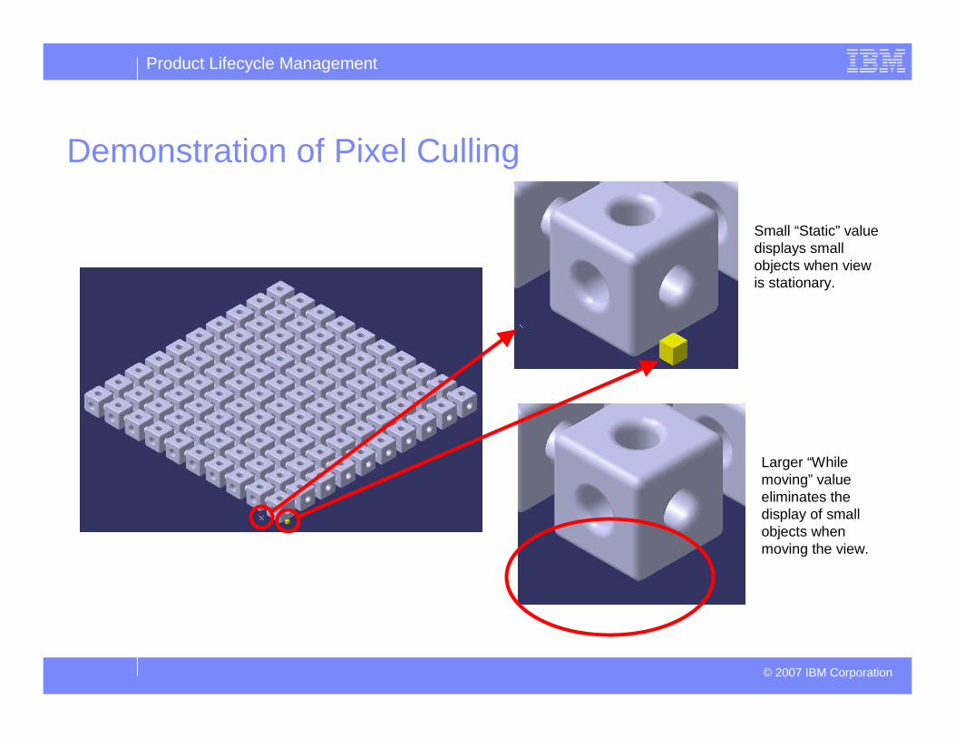
Demonstration of Pixel Culling
Small “Static” value displays small objects when view is stationary.
Larger “While moving” value eliminates the display of small objects when moving the view.

Product Lifecycle Management
© 2007 IBM Corporation
Settings to enhance graphics performance
Use Shading without edges (SHD)

Product Lifecycle Management
© 2007 IBM Corporation
Settings to enhance graphics performanceTools└ Options└ General└ Display – Navigation tab
Uncheck – Animation during viewpoint modification
For graphically “heavy” scenes, intermediate visualizations may help orient the viewer, but can be annoying for the user familiar with the data.

Product Lifecycle Management
© 2007 IBM Corporation
Settings to improve interactive performance- Minimize what is loaded to memory
Tools└ Options└ Infrastructure└ Product Structure – Cache Management tab
Check - Work with the cache system
Enables working in visualization mode with cgr’s.
Exploit selective loading technology
If you’re confident of cache content, uncheck “Check timestamps” for even faster loading.
Product Lifecycle Management
© 2007 IBM Corporation
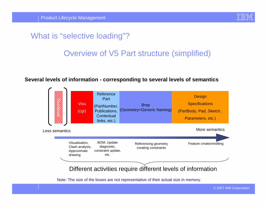
What is “selective loading”?
Overview of V5 Part structure (simplified)
Several levels of information - corresponding to sev eral levels of semantics
Visu
(cgr)
Brep(Geometry+Generic Naming)
Design
Specifications
(PartBody, Pad, Sketch,
Parameters, etc.)
Less semantics More semantics
Visualisation, Clash analysis, Approximate drawing
Referencing geometry creating constraints
Feature creation/editing
Thum
bnail
Reference Part
(PartNumber,Publications, Contextual links, etc.)
BOM, Update diagnostic,
constraint update, etc.
Note: The size of the boxes are not representative of their actual size in memory.
Different activities require different levels of information
Product Lifecycle Management
© 2007 IBM Corporation
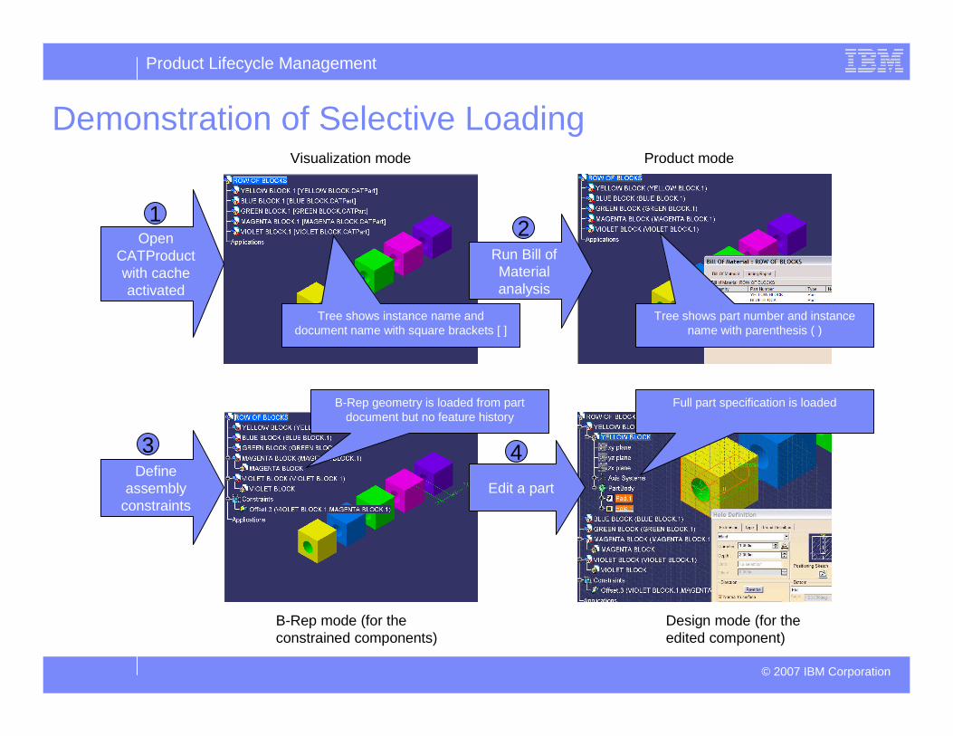
Demonstration of Selective Loading
Run Bill of Material analysis
Visualization mode Product mode
B-Rep mode (for the constrained components)
Design mode (for the edited component)
Define assembly
constraintsEdit a part
Tree shows instance name and document name with square brackets [ ]
Tree shows part number and instance name with parenthesis ( )
Full part specification is loadedB-Rep geometry is loaded from part document but no feature history
2
43
Open CATProduct with cache activated
1

Product Lifecycle Management
© 2007 IBM Corporation
Settings to improve interactive performance- Improve loading performance
Tools└ Options└ General – Document tab
Linked Document LocalizationRemove unnecessary locations from list
Default has all values set to “Yes”
Need to adjust list based on your environment
Can dramatically affect load times if linked documents are not found
Product Lifecycle Management
© 2007 IBM Corporation
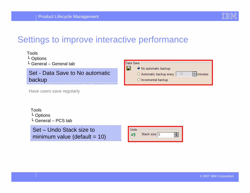
Settings to improve interactive performanceTools└ Options└ General – General tab
Set - Data Save to No automatic backup
Tools└ Options└ General – PCS tab
Set – Undo Stack size to minimum value (default = 10)
Have users save regularly

Product Lifecycle Management
© 2007 IBM Corporation
Operational Suggestions:
•Use F3 to Toggle off spec tree
•Use Sub-Trees contextual command (right mouse button)
•Unaffected by F3 (can have main tree hidden with sub-trees active)
•Can have multiple sub-trees displayed and active
•Use Tree Overview
•If doing purely tree-related activities, turn off geometry display (View/Geometry)
•Use Look-at command
•Use Trap over geometry

Product Lifecycle Management
© 2007 IBM Corporation
Operational Suggestions
� Minimize what is loaded in your session
– Uncheck – load referenced documents
– Check – Do not load default shapes on open
– Utilize loading commands:
• Load (will load everything under selected node)• Selective Load (user sets how many levels to load)• Activate/Deactivate Node• Activate/Deactivate Terminal Node• Define and use Selection Sets for frequent selections

Product Lifecycle Management
© 2007 IBM Corporation
Adhere to data structure guidelines:� Keep parts at terminal nodes
� Upper levels of the product structure should contain sub-products or reference parts:– It is better to structure with several small sub-as semblies (200 or 300 parts)
� Minimize depth of product structure

Product Lifecycle Management
© 2007 IBM Corporation
Adhere to data structure guidelines:
� Always create 3D constraints between parts of the same CATProduct or between parts of two CATProducts of the same level.
� Minimize constraints creation and parts impacted by constraints
� Establish a driver part (skeleton part)

Product Lifecycle Management
© 2007 IBM Corporation
Adhere to data structure guidelines:
Use publications to facilitate replace operations and to reinforce the design links between different levels of the Product Structure.

Product Lifecycle Management
© 2007 IBM Corporation
Hardware and OS Considerations
� Use Dassault Certified (or derived) Platform Configurationshttp://www.3ds.com/support/workstations-peripherals/
– Derived platforms are not specifically tested by Dassault. They differ from certified platforms by clock speed, disk, network subsystem, and texture memory, but retain equivalent processor model, chipset, and graphics card.
Product Lifecycle Management
© 2007 IBM Corporation
Hardware and OS Considerations
32-bit OS
� Addressable Memory is the main limiting factor when working with large assemblies
– Addressable Memory is Real Memory (RAM) + Virtual Memory (swap or paging space on disk)
� 32 bit Windows is limited to a maximum of 4 Gb total, split between user applications and operating system kernel needs. By default, user applications are limited to 2Gb total. The OS can be adjusted to allow up to 3Gb total for applications. See “Accessing more than 2.0 GB of memory on Windows XP” in the CATIA Program Directory
� With CATIA on Windows XP, demands exceeding the Addressable Memory size can cause lockups and possible data loss. The memory warning setting can be activated under Tools/Options/General – General tab to alert users to this condition.

Product Lifecycle Management
© 2007 IBM Corporation
Hardware and OS Considerations
64-bit OS
� 64-bit Operating Systems have practically unlimited addressable memory (16 Terabytes)
– Can typically get up to 8Gb RAM per processor today
– Virtual memory is limited by hard disk capacity (but is slower than RAM)
� Can run 32-bit CATIA on Windows XP Professional x64 Edition with up to 4Gb per process. Compare this with a maximum of 3Gb TOTAL for ALL applications on 32-bit Windows.
� Generally, operations that are not memory constrained on 32-bit may not see significant performance boosts by simply switching to 64-bit.
� Additional registers with 64-bit can benefit operations with intensive floating point operations such as finite element analysis and NC tool path computations.
� 64-bit CATIA will require recompiling custom (CAA) code

Product Lifecycle Management
© 2007 IBM Corporation
Hardware and OS Considerations
Multi-core, Multi-CPU
� In general, CATIA V5 is not a multi-threaded application
� Multi-threaded CATIA V5 operations include
– Render (shading)
– Occlusion culling
– DMU Clash Analysis
– cgr generation
– Finite Element Analysis

Product Lifecycle Management
© 2007 IBM Corporation
Hardware and OS Considerations
IBM-specific tuning and setup instructions for Inte lliStation workstations and ThinkPad laptops
� Developed by dedicated IBM workstation specialist on-site at Dassault Systèmes in France
� Collaborative work between CATIA software developers, IBM hardware engineers, and graphics card vendors
� Intended to ensure optimized graphics and system performance when running CATIA applications on IBM hardware
� Available from a link on the IBM PLM Technical Support web pagehttp://www.ibm.com/software/applications/plm/support

Product Lifecycle Management
© 2007 IBM Corporation
Hardware and OS Considerations

Product Lifecycle Management
© 2007 IBM Corporation
Hardware and OS Considerations

Product Lifecycle Management
© 2007 IBM Corporation
Remember:
� Be smart about CATIA settings
� Load and Display only what you need
� Establish sound work practices
� Be aware of tools and techniques
� Don’t skimp on Hardware

Product Lifecycle Management
© 2007 IBM Corporation
Thank You!