CODE OF PRACTICE FOR THE CONSTRUCTION OF - We · PDF fileCode of Practice for the Construction...
67
CODE OF PRACTICE FOR THE CONSTRUCTION OF HOUSES: AN INSTRUCTION MANUAL FOR FOREMEN AND EXPERIENCED ARTISANS PART 2: STUDENT’S MANUAL
Transcript of CODE OF PRACTICE FOR THE CONSTRUCTION OF - We · PDF fileCode of Practice for the Construction...
CODE OF PRACTICE FOR THE CONSTRUCTION OF HOUSES: AN
INSTRUCTION MANUAL FOR FOREMEN AND EXPERIENCED
ARTISANS
PART 2: STUDENT’S MANUAL
Page 2 of 67
Code of Practice for the Construction of Houses: An Instruction Manual for Foremen and Experienced Artisans
Part 2: Student’s Manual
CARIBBEN DISASTER EMERGENCY RESPONSE AGENCY (CDERA)
AUGUST 2005
Code of Practice for the Construction of Houses: An Instruction Manual for Foremen and Experienced Artisans
Table of Contents
FOREWORD ............................................................................................................................................. 4 ACKNOWLEDGEMENTS....................................................................................................................... 6 INTRODUCTION ...................................................................................................................................... 7 1 SCOPE ............................................................................................................................................... 8 2 NORMATIVE REFERENCES ......................................................................................................... 8 3 TERMS AND DEFINITIONS ........................................................................................................... 8 4 GENERAL PRINCIPLES ................................................................................................................. 9 5 PRE-CONSTRUCTION PLANNING ............................................................................................. 9
5.1 PLANNING APPROVAL .............................................................................................10 5.2 CONTRACT WITH THE CLIENT ...................................................................................10 5.3 SAFE BUILDING ......................................................................................................10 5.4 QUALITY OF MATERIALS..........................................................................................10 5.5 STORAGE OF CONSTRUCTION MATERIALS ................................................................12 5.6 PROTECTION OF REINFORCED CONCRETE (RC) ........................................................13 5.7 QUALITY OF CONNECTIONS .....................................................................................14 5.8 REINFORCEMENT LAP LENGTHS ..............................................................................15 5.9 STRUCTURAL STABILITY..........................................................................................16 5.10 TYPICAL PRE- CONSTRUCTION PLANNING DETAILS .....................................................16
6 SITE PREPARATION .................................................................................................................... 24 6.1 SITE CONDITION ......................................................................................................24 6.2 CLEARING THE SITE ................................................................................................25 6.3 SETTING OUT..........................................................................................................25 6.4 ACCESS TO ROADS .................................................................................................27
7 FOUNDATIONS .............................................................................................................................. 28 7.1 EXCAVATIONS ........................................................................................................28 7.2 TIMBER POST FOUNDATIONS ....................................................................................29 7.3 PAD FOOTINGS .......................................................................................................29 7.4 STRIP FOOTINGS .....................................................................................................32 7.5 RAFT FOUNDATION..................................................................................................34 7.6 TYPICAL FOUNDATION DETAILS ...............................................................................37
8. FLOORS ........................................................................................................................................... 42 8.1 RAFT FOUNDATION WITH GROUND FLOOR SLAB .........................................................42 8.2 REINFORCED CONCRETE GROUND FLOOR SLAB SUPPORTED ON STRIP FOOTINGS .......42 8.3 SUSPENDED REINFORCED CONCRETE FLOOR SLAB ON PAD FOOTINGS. .......................44 8.4 SUSPENDED TIMBER GROUND FLOOR SUPPORTED ON REINFORCED CONCRETE BEAMS.46 8.5 TYPICAL FLOOR DETAILS ........................................................................................48
9. WALLS.............................................................................................................................................. 50 9.1 CONCRETE BLOCK WALLS .......................................................................................50 9.2 TIMBER WALLS .......................................................................................................51 9.3 TYPICAL WALL DETAILS..........................................................................................52
10. ROOFS .............................................................................................................................................. 55 10.1 TIMBER ROOF STRUCTURE ON CONCRETE BLOCK WALL .............................................55 10.2 TIMBER ROOF STRUCTURE ON TIMBER WALL .............................................................55 10.3 TYPICAL ROOF DETAILS ..........................................................................................59 10.4 REPAIRING AND REPLACING A ROOF LOST TO HIGH WINDS..........................................64
11 POST-CONSTRUCTION MAINTENANCE ................................................................................ 65 11.1 MAINTENANCE INSPECTION TYPES............................................................................65
ANNEX A ................................................................................................................................................. 67
Code of Practice for the Construction of Houses: An Instruction Manual for Foremen and Experienced Artisans
Page 4 of 67
Foreword The Code of Practice for the Construction of Houses: An Instruction Manual for Foremen and Experienced Artisans was prepared by the CARICOM Regional Organisation for Standards and Quality (CROSQ) through its Technical Management Committee. The Code of Practice is based upon previous initiatives in the Caribbean to address Safe Building in the informal and formal sector. The Trainer’s and Student’s Manual were developed by the Caribbean Disaster Emergency Response Agency (CDERA) with the assistance of the Organisation of American States (OAS) and funding support from the Canadian International Development Agency (CIDA) under the Caribbean Hazard Mitigation Capacity Building Programme (CHAMP). Through CHAMP there has been an assessment of the quality of existing building practices in the informal sector, the opportunities for training, the capacity of local technical institutes, the level of existing building standards and the framework for development control and review. This assessment has established a baseline of existing training activities in the informal sector which has informed the development of a Safer Building curriculum for training. The curriculum has been based upon the contents of the Organisation of Eastern Caribbean Sates (OECS) Building Guidelines and has been tested at the regional level through a regional train-the-trainers workshop in Grenada and a national train-the-trainers workshop in Belize in April 2005. Subsequently, the curriculum has been refined and has been used to deliver national training in the three CHAMP pilot states of Belize, Grenada and St. Lucia and in the British Virgin Islands. A technical working group consisting of regional trade schools who would ultimately teach the curriculum, as well as lending institutions which offer residential mortgages around the Caribbean was established by CDERA to elaborate upon the Safer Building course curriculum. Further technical support was provided by the Organisation of American States (OAS) and the membership of the CDERA Thematic Cooperating Group on Safer Building (a group of safer building experts), who assisted in review of the document. In August, 2005 CDERA initiated discussions with the CARICOM Regional Organisation for Standards and Quality (CROSQ) Technical Management Committee regarding acceptance of its Safer Building Course. In November, 2005 a special CROSQ Technical Management Committee meeting was convened to review the curriculum, student’s manual and trainer’s manual of the Safer Building Course. CDERA revised the document to reflect recommendations of the Technical Management Committee and the documents were re-circulated to stakeholders for further comments. On February 15, 2006 the CROSQ Editorial Committee was convened to edit the document now renamed Code of Practice for Safer Building. The Code of Practice for Construction of Houses: An Instruction Manual for Foremen and Experienced Artisans has been referred to the CROSQ Council (March 9-10, 2006) for endorsement. This document has been drafted in accordance with the ISO/IEC Directives, Part 2: Rules for the structure and drafting of International Standards. This document is Part 2 in the two part series- Code of Practice for Construction of Houses: An Instruction Manual for Foremen and Experienced Artisans and should be read in conjunction with the Code of Practice for Construction of Houses: An Instruction Manual for Foremen and

Code of Practice for the Construction of Houses: An Instruction Manual for Foremen and Experienced Artisans
Page 5 of 67
Experienced Artisans Part 1: Trainer’s Manual. The next maintenance date for this document is April, 2009.
Code of Practice for the Construction of Houses: An Instruction Manual for Foremen and Experienced Artisans
Page 6 of 67
Acknowledgements The Caribbean Disaster Emergency Response Agency (CDERA) wishes to convey its sincere appreciation and profound gratitude to its many partners who contributed to the successful development of the first Code of Practice for Construction of Houses: An Instruction Manual for Foremen and Experienced Artisans in the Caribbean. A technical working group was established by CDERA through Consulting Engineers Partnership Ltd. (CEP) to elaborate upon the Construction of Houses: An Instruction Manual for Foremen and Experienced Artisans course curriculum and training materials. Participants included the Samuel Jackman Prescod Polytechnic; Barbados, Technical & Vocational Education & Training Council; Barbados, Centre for Employment Training; Belize, T A Marryshow Community College; Grenada, St Patrick’s Multi Purpose Centre; Grenada, H. Lavity Stoutt Community College; British Virgin Islands, Sir Arthur Lewis Community College; St Lucia, University of Technology, Jamaica; Insurance Association of the Caribbean; the Caribbean Association of Indigenous Banks; and the CARICOM Regional Organisation for Standards and Quality (CROSQ). Further technical support was provided by the Organisation of American States (OAS) and the membership of the CDERA Thematic Cooperating Group on Safer Building, who assisted in the review of the document. In addition the CARICOM Regional Organisation for Standards and Quality (CROSQ) through its Technical Management Committee and Editorial Committee facilitated finalisation of the document. The production of this document has been made possible by the financial support of the Canadian International Development Agency (CIDA).
Code of Practice for the Construction of Houses: An Instruction Manual for Foremen and Experienced Artisans
Page 7 of 67
Introduction The geographic location of the Caribbean region, which has been the source of its appeal for its residents and visitors alike, is also the basis of its vulnerability to natural hazards such as tropical storms, hurricanes, flooding, volcanic eruptions, fires and land slippages. Within the region, direct and indirect damages from natural hazards over the past thirty years have been estimated at between US$700 million and $3.3 billion annually. A large portion of the wealth of any nation is invested in its built environment: housing, infrastructure, industrial and commercial facilities. Statistics indicate that in recent times there has been an increase in damage due to inappropriate building practices (both construction methods and materials) and improper siting which have been primarily driven by commerce. The development of a building regulatory system (building codes, land use and development plans, and an inspection mechanism) plays an important role in ensuring the quality of the built environment. A large percentage of houses in the Caribbean are constructed by the informal building sector which operates outside the formal construction industry which is regulated by the standards of building and planning authorities. This sector is dominated by small contractors and builders with little regard for building standards and codes. Moreover, many practitioners within the sector, in most instances, have never received formal skills training or certification. Training for individuals in all parts of the construction industry in appropriate building techniques is an important counterpart to codes and regulations and can significantly enhance the quality of this very vulnerable sector of the housing market. Building upon the foundation created by previous Caribbean initiatives such as the Organisation of American States (OAS) led Caribbean Disaster Mitigation Project (CDMP) and the Post Georges Disaster Mitigation Project (PGDM) in both the formal and informal building sectors, the Caribbean Hazard Mitigation Capacity Building Programme (CHAMP) was developed in 2001 as a mechanism through which many of the lessons learnt and gains of past initiatives could be consolidated and advanced. The three year Canadian International Development Agency (CIDA) funded CHAMP programme recognized the gaps in these various interventions and sought to produce a cadre of regional building professionals who were certified in safer building techniques within the informal sector, as well as materials suppliers who would stock safer building materials. To be successful, it was recognised that the certification process would have be achieved at the level of CARICOM for the movement of skills within the Caribbean Single Market and Economy (CSME) and so as a first step CDERA initiated discussions with the CARICOM Regional Organisation for Standards and Quality (CROSQ) to obtain their support for a common accredited Caribbean residential construction curriculum that would be the basis of the artisan’s regional certification. Based on recommendations from the CROSQ Technical Management Committee the Safer Building Curriculum has been revised to a Code of Practice for Construction of Houses: An Instruction Manual for Foremen and Experienced Artisans.
Code of Practice for the Construction of Houses: An Instruction Manual for Foremen and Experienced Artisans
Page 8 of 67
1 Scope The information in this Code is designed to certify residential contractors so that they can construct homes in the Caribbean that are less vulnerable to natural hazards. Plumbing and electrical standards are not included in this Code, but can be found in the national building standards. 2 Normative References The following documents were used in the preparation of the Code.
a) Barbados National Standards Institute, Barbados National Building Code, 1993; b) Organisation of Eastern Caribbean States, Grenada Building Guidelines, 1999; c) Virgin Islands, Building Regulations, 1999; d) Belize Chamber of Commerce and Industry, Belize Residential Construction
Standards, 1999. 3 Terms and Definitions The following terms and definitions are relevant for this document. House - single family dwelling. Joint – connection between two structural elements. Lap length – distance where two reinforcing bars are spliced. Competent authority – the government’s regulatory department responsible for building standards. Set back – distance from the boundary to the external wall of the building. Safe building – constructing a building with a low vulnerability to natural hazards. Illustration – drawing. Buildability - the extent to which the design of the building facilitates ease of construction, subject to the overall requirements for the completed building. Pyroclastic flows- normally result from volcanic eruptions. They are fast moving fluidized bodies of hot gas, ash and rock which can travel away from the vent at up to 150 km/h. The gas is usually at a temperature of 100 oC to 800 oC. The flows normally hug the ground and travel downhill under gravity, their speed depending upon the gradient of the slope and the size of the flow.
Code of Practice for the Construction of Houses: An Instruction Manual for Foremen and Experienced Artisans
Page 9 of 67
Well graded granular fill – granular fill with a good representation of particle sizes over a wide range. Plastic chairs – a seat for steel reinforcement used to raise the reinforcement to the correct level. Raft foundation – a foundation that incorporates the wall foorings into the floor slab. Lintel – a horizontal beam over a window or doorway. Epoxy grout - A two-part grout system consisting of epoxy resin and epoxy hardener, especially formulated to have impervious qualities, stain, and chemical resistance. 4 General Principles This course is designed to provide construction foremen with specific information to reduce the vulnerability of houses to natural hazards in the Caribbean. 5 Pre-construction planning For constructing a new building the following are required:
a) planning approval; b) contract with the client; c) an understanding of safe building; d) the selection of quality material; e) proper storage of construction materials; f) the protection of reinforced concrete; g) the use of good quality joints; h) the use of adequate reinforcement lap lengths; i) an understanding of structural stability methods.
Code of Practice for the Construction of Houses: An Instruction Manual for Foremen and Experienced Artisans
Page 10 of 67
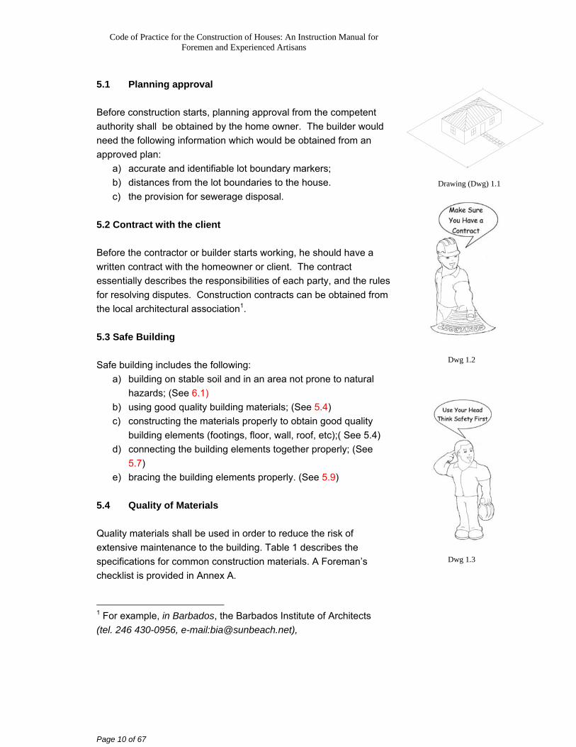
5.1 Planning approval Before construction starts, planning approval from the competent authority shall be obtained by the home owner. The builder would need the following information which would be obtained from an approved plan:
a) accurate and identifiable lot boundary markers; b) distances from the lot boundaries to the house. c) the provision for sewerage disposal.
5.2 Contract with the client Before the contractor or builder starts working, he should have a written contract with the homeowner or client. The contract essentially describes the responsibilities of each party, and the rules for resolving disputes. Construction contracts can be obtained from the local architectural association1. 5.3 Safe Building Safe building includes the following:
a) building on stable soil and in an area not prone to natural hazards; (See 6.1)
b) using good quality building materials; (See 5.4) c) constructing the materials properly to obtain good quality
building elements (footings, floor, wall, roof, etc);( See 5.4) d) connecting the building elements together properly; (See
5.7) e) bracing the building elements properly. (See 5.9)
5.4 Quality of Materials Quality materials shall be used in order to reduce the risk of extensive maintenance to the building. Table 1 describes the specifications for common construction materials. A Foreman’s checklist is provided in Annex A. 1 For example, in Barbados, the Barbados Institute of Architects (tel. 246 430-0956, e-mail:[email protected]),
Drawing (Dwg) 1.1
Dwg 1.2
Dwg 1.3
Code of Practice for the Construction of Houses: An Instruction Manual for Foremen and Experienced Artisans
Page 11 of 67
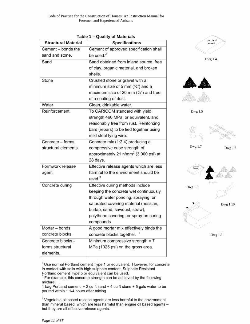
Table 1 – Quality of Materials
Structural Material Specifications Cement – bonds the sand and stone.
Cement of approved specification shall be used.2
Sand Sand obtained from inland source, free of clay, organic material, and broken shells.
Stone Crushed stone or gravel with a minimum size of 5 mm (¼”) and a maximum size of 20 mm (⅞”) and free of a coating of dust.
Water Clean, drinkable water. Reinforcement To CARICOM standard with yield
strength 460 MPa, or equivalent, and reasonably free from rust. Reinforcing bars (rebars) to be tied together using mild steel tying wire.
Concrete – forms structural elements.
Concrete mix (1:2:4) producing a compressive cube strength of approximately 21 n/mm2 (3,000 psi) at 28 days.
Formwork release agent
Effective release agents which are less harmful to the environment should be used.3
Concrete curing Effective curing methods include keeping the concrete wet continuously through water ponding, spraying, or saturated covering material (hessian, burlap, sand, sawdust, straw), polythene covering, or spray-on curing compounds
Mortar – bonds concrete blocks.
A good mortar mix effectively binds the concrete blocks together. 4
Concrete blocks - forms structural elements.
Minimum compressive strength = 7 MPa (1025 psi) on the gross area.
2 Use normal Portland cement Type 1 or equivalent. However, for concrete in contact with soils with high sulphate content, Sulphate Resistant Portland cement Type 5 or equivalent can be used. 3 For example, this concrete strength can be achieved by the following mixture: 1 bag Portland cement + 2 cu ft sand + 4 cu ft stone + 5 gals water to be poured within 1 1/4 hours after mixing 3 Vegetable oil based release agents are less harmful to the environment than mineral based, which are less harmful than engine oil based agents – but they are all effective release agents.
port landcement
Dwg 1.4
Dwg 1.5
Dwg 1.6
port landcement
Dwg 1.7
Dwg 1.10
Dwg 1.8
Dwg 1.9
Code of Practice for the Construction of Houses: An Instruction Manual for Foremen and Experienced Artisans
Page 12 of 67
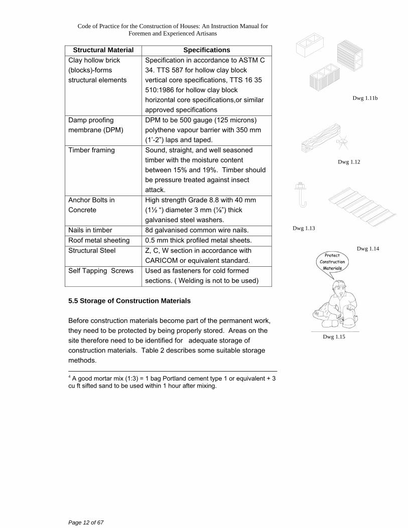
Structural Material Specifications Clay hollow brick (blocks)-forms structural elements
Specification in accordance to ASTM C 34. TTS 587 for hollow clay block vertical core specifications, TTS 16 35 510:1986 for hollow clay block horizontal core specifications,or similar approved specifications
Damp proofing membrane (DPM)
DPM to be 500 gauge (125 microns) polythene vapour barrier with 350 mm (1’-2”) laps and taped.
Timber framing Sound, straight, and well seasoned timber with the moisture content between 15% and 19%. Timber should be pressure treated against insect attack.
Anchor Bolts in Concrete
High strength Grade 8.8 with 40 mm (1½ “) diameter 3 mm (⅛”) thick galvanised steel washers.
Nails in timber 8d galvanised common wire nails. Roof metal sheeting 0.5 mm thick profiled metal sheets. Structural Steel Z, C, W section in accordance with
CARICOM or equivalent standard. Self Tapping Screws Used as fasteners for cold formed
sections. ( Welding is not to be used) 5.5 Storage of Construction Materials Before construction materials become part of the permanent work, they need to be protected by being properly stored. Areas on the site therefore need to be identified for adequate storage of construction materials. Table 2 describes some suitable storage methods. 4 A good mortar mix (1:3) = 1 bag Portland cement type 1 or equivalent + 3 cu ft sifted sand to be used within 1 hour after mixing.
Dwg 1.15
Dwg 1.12
Dwg 1.13
Dwg 1.14
Dwg 1.11b
Code of Practice for the Construction of Houses: An Instruction Manual for Foremen and Experienced Artisans
Page 13 of 67
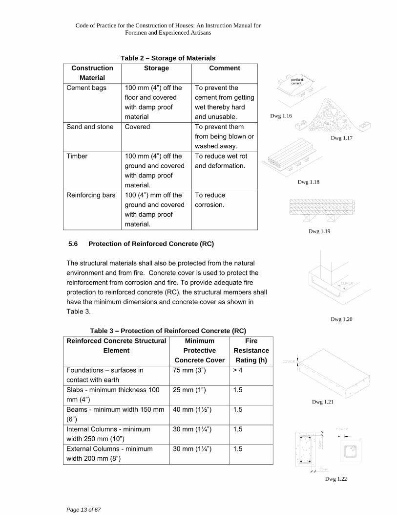
Table 2 – Storage of Materials
Construction Material
Storage Comment
Cement bags 100 mm (4”) off the floor and covered with damp proof material
To prevent the cement from getting wet thereby hard and unusable.
Sand and stone Covered To prevent them from being blown or washed away.
Timber 100 mm (4”) off the ground and covered with damp proof material.
To reduce wet rot and deformation.
Reinforcing bars 100 (4”) mm off the ground and covered with damp proof material.
To reduce corrosion.
5.6 Protection of Reinforced Concrete (RC)
The structural materials shall also be protected from the natural environment and from fire. Concrete cover is used to protect the reinforcement from corrosion and fire. To provide adequate fire protection to reinforced concrete (RC), the structural members shall have the minimum dimensions and concrete cover as shown in Table 3.
Table 3 – Protection of Reinforced Concrete (RC)
Reinforced Concrete Structural Element
Minimum Protective
Concrete Cover
Fire Resistance Rating (h)
Foundations – surfaces in contact with earth
75 mm (3”) > 4
Slabs - minimum thickness 100 mm (4”)
25 mm (1”) 1.5
Beams - minimum width 150 mm (6”)
40 mm (1½”) 1.5
Internal Columns - minimum width 250 mm (10”)
30 mm (1¼”) 1.5
External Columns - minimum width 200 mm (8”)
30 mm (1¼”) 1.5
port landcement
Dwg 1.17
Dwg 1.18
Dwg 1.19
Dwg 1.20
Dwg 1.21
Dwg 1.22
Dwg 1.16
Code of Practice for the Construction of Houses: An Instruction Manual for Foremen and Experienced Artisans
Page 14 of 67
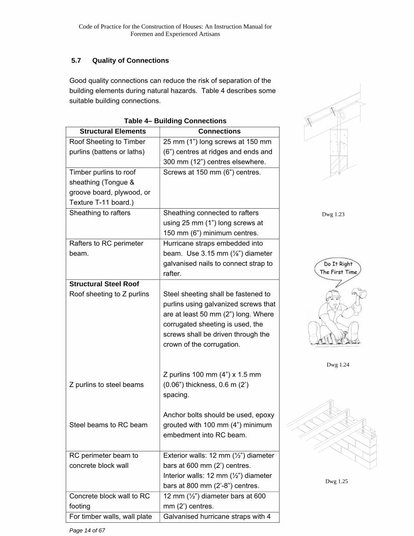
5.7 Quality of Connections Good quality connections can reduce the risk of separation of the building elements during natural hazards. Table 4 describes some suitable building connections.
Table 4– Building Connections
Structural Elements Connections Roof Sheeting to Timber purlins (battens or laths)
25 mm (1”) long screws at 150 mm (6”) centres at ridges and ends and 300 mm (12”) centres elsewhere.
Timber purlins to roof sheathing (Tongue & groove board, plywood, or Texture T-11 board.)
Screws at 150 mm (6”) centres.
Sheathing to rafters Sheathing connected to rafters using 25 mm (1”) long screws at 150 mm (6”) minimum centres.
Rafters to RC perimeter beam.
Hurricane straps embedded into beam. Use 3.15 mm (⅛”) diameter galvanised nails to connect strap to rafter.
Structural Steel Roof Roof sheeting to Z purlins Z purlins to steel beams Steel beams to RC beam
Steel sheeting shall be fastened to purlins using galvanized screws that are at least 50 mm (2”) long. Where corrugated sheeting is used, the screws shall be driven through the crown of the corrugation. Z purlins 100 mm (4”) x 1.5 mm (0.06”) thickness, 0.6 m (2’) spacing. Anchor bolts should be used, epoxy grouted with 100 mm (4”) minimum embedment into RC beam.
RC perimeter beam to concrete block wall
Exterior walls: 12 mm (½”) diameter bars at 600 mm (2’) centres. Interior walls: 12 mm (½”) diameter bars at 800 mm (2’-8”) centres.
Concrete block wall to RC footing
12 mm (½”) diameter bars at 600 mm (2’) centres.
For timber walls, wall plate Galvanised hurricane straps with 4
Dwg 1.23
Dwg 1.24
Dwg 1.25
Code of Practice for the Construction of Houses: An Instruction Manual for Foremen and Experienced Artisans
Page 15 of 67
Structural Elements Connections to timber studs to sole plate to foundation
x 8d galvanised common wire nails or two 12 mm (¼”) dia. bolts in each member.
Footing to ground In soil: Cast bottom of footing 900 mm (3’) below surface. In Rock: Cut 50 mm (2”) minimum into rock.
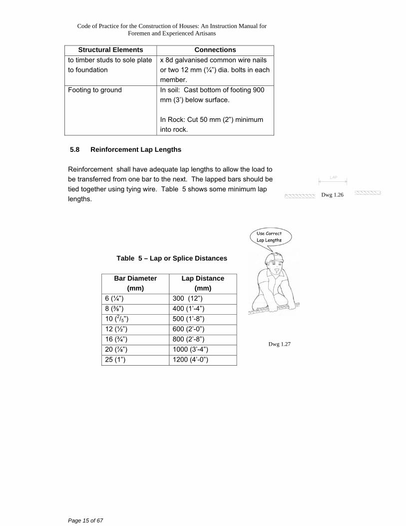
5.8 Reinforcement Lap Lengths Reinforcement shall have adequate lap lengths to allow the load to be transferred from one bar to the next. The lapped bars should be tied together using tying wire. Table 5 shows some minimum lap lengths.
Table 5 – Lap or Splice Distances
Bar Diameter (mm)
Lap Distance (mm)
6 (¼”) 300 (12”) 8 (⅜”) 400 (1’-4”) 10 (2/5”) 500 (1’-8”) 12 (½”) 600 (2’-0”) 16 (¾”) 800 (2’-8”) 20 (⅞”) 1000 (3’-4”) 25 (1”) 1200 (4’-0”)
Dwg 1.26
Dwg 1.27
Code of Practice for the Construction of Houses: An Instruction Manual for Foremen and Experienced Artisans
Page 16 of 67
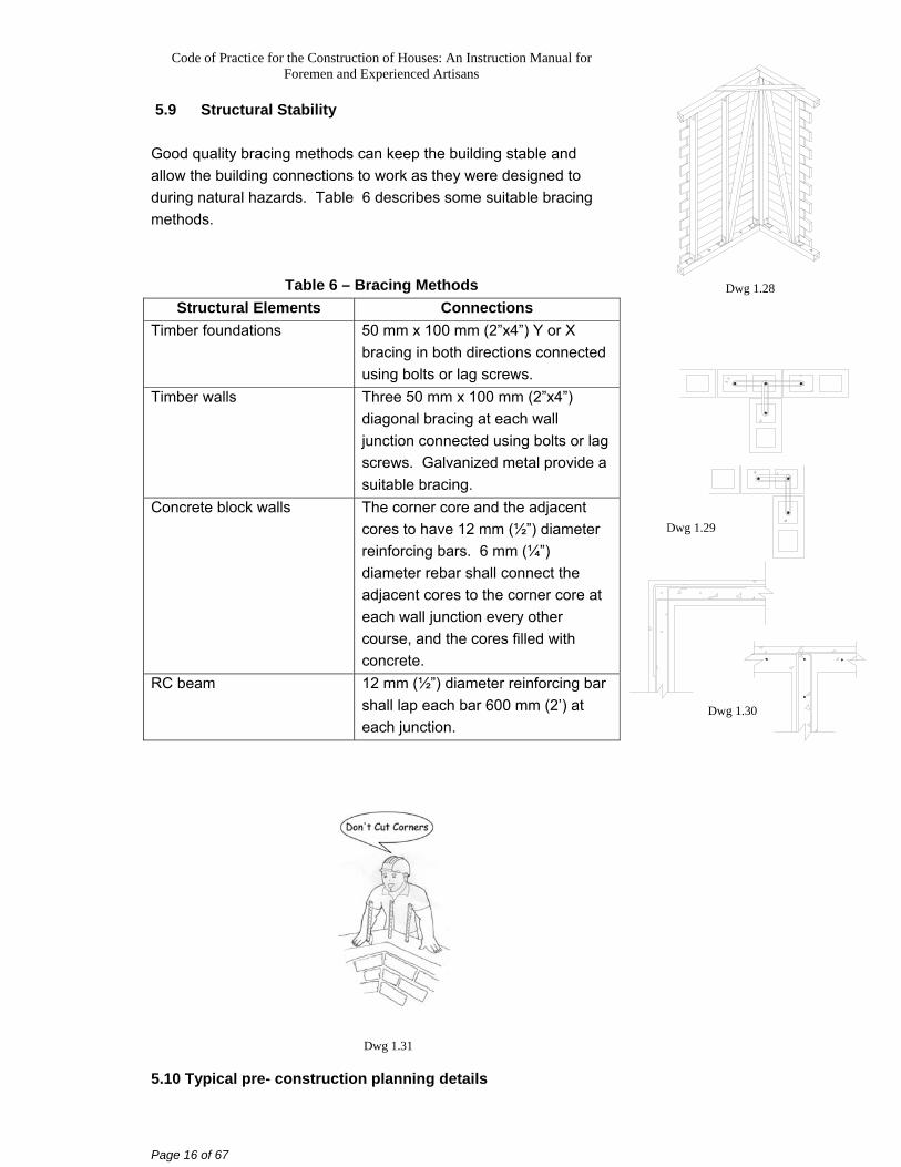
5.9 Structural Stability Good quality bracing methods can keep the building stable and allow the building connections to work as they were designed to during natural hazards. Table 6 describes some suitable bracing methods.
Table 6 – Bracing Methods
Structural Elements Connections Timber foundations 50 mm x 100 mm (2”x4”) Y or X
bracing in both directions connected using bolts or lag screws.
Timber walls Three 50 mm x 100 mm (2”x4”) diagonal bracing at each wall junction connected using bolts or lag screws. Galvanized metal provide a suitable bracing.
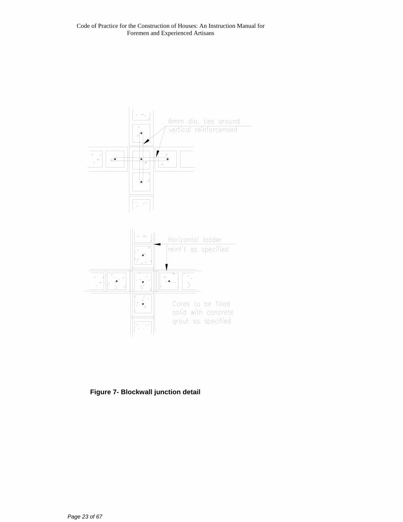
Concrete block walls The corner core and the adjacent cores to have 12 mm (½”) diameter reinforcing bars. 6 mm (¼”) diameter rebar shall connect the adjacent cores to the corner core at each wall junction every other course, and the cores filled with concrete.
RC beam 12 mm (½”) diameter reinforcing bar shall lap each bar 600 mm (2’) at each junction.
5.10 Typical pre- construction planning details
Dwg 1.28
Dwg 1.29
Dwg 1.30
Dwg 1.31
Code of Practice for the Construction of Houses: An Instruction Manual for Foremen and Experienced Artisans
Page 17 of 67
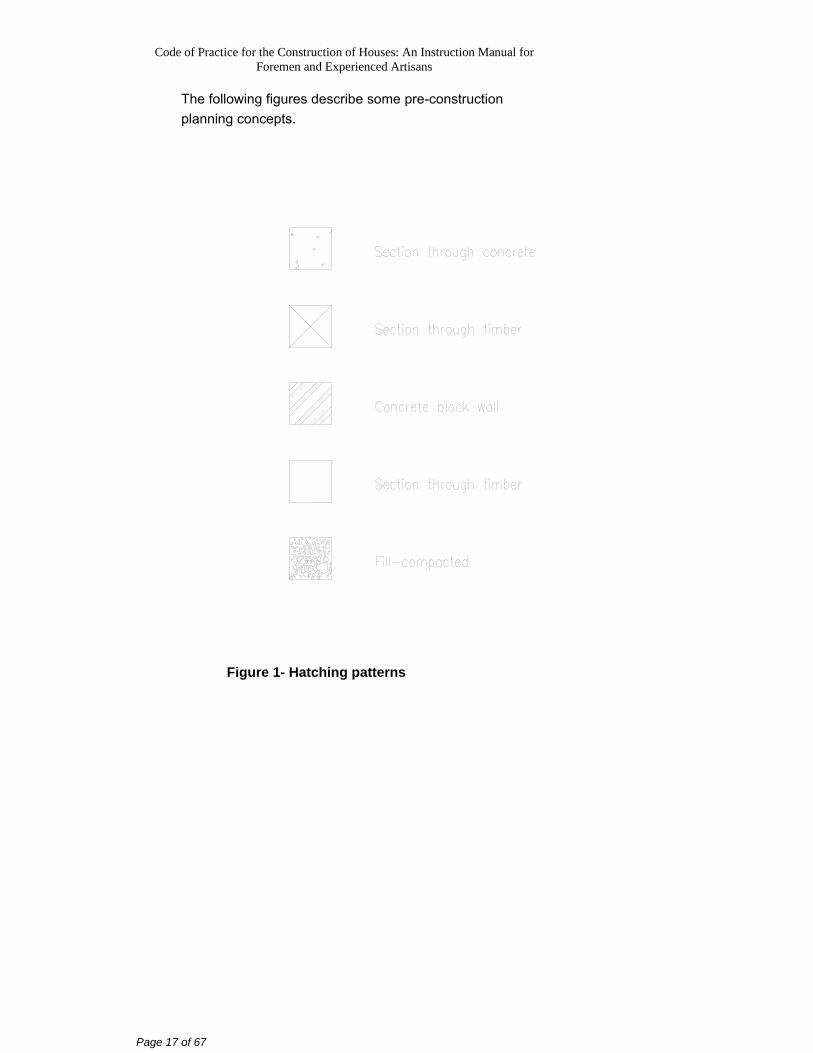
The following figures describe some pre-construction planning concepts.
Figure 1- Hatching patterns
Code of Practice for the Construction of Houses: An Instruction Manual for Foremen and Experienced Artisans
Page 18 of 67
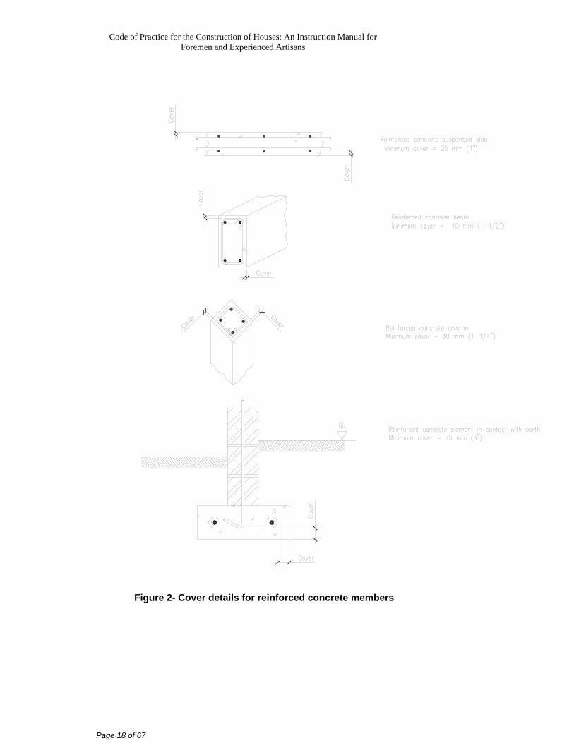
Figure 2- Cover details for reinforced concrete members
Code of Practice for the Construction of Houses: An Instruction Manual for Foremen and Experienced Artisans
Page 19 of 67
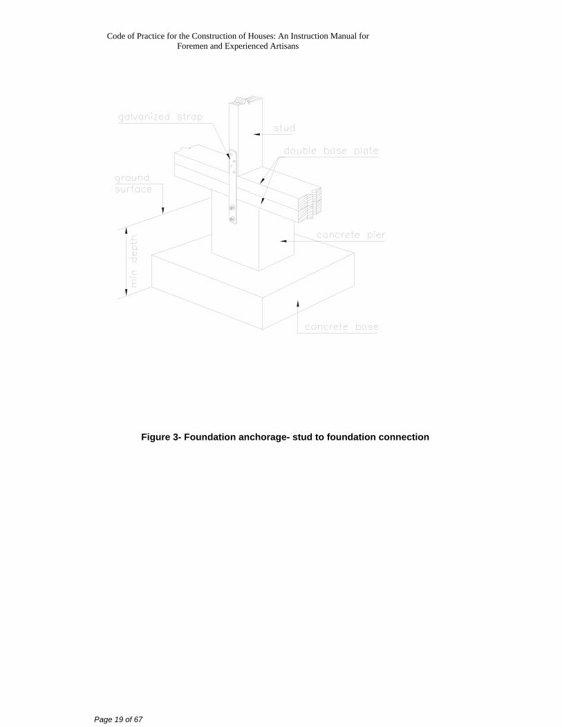
Figure 3- Foundation anchorage- stud to foundation connection
Code of Practice for the Construction of Houses: An Instruction Manual for Foremen and Experienced Artisans
Page 20 of 67
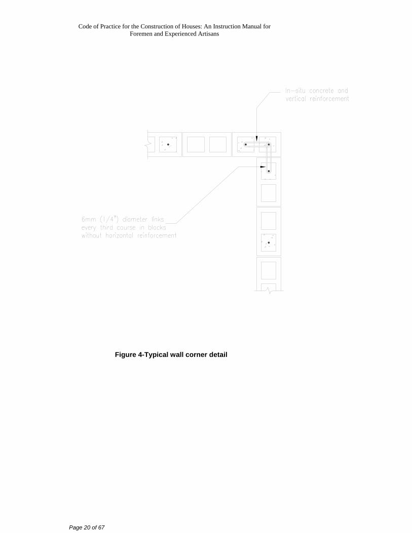
Figure 4-Typical wall corner detail
Code of Practice for the Construction of Houses: An Instruction Manual for Foremen and Experienced Artisans
Page 21 of 67
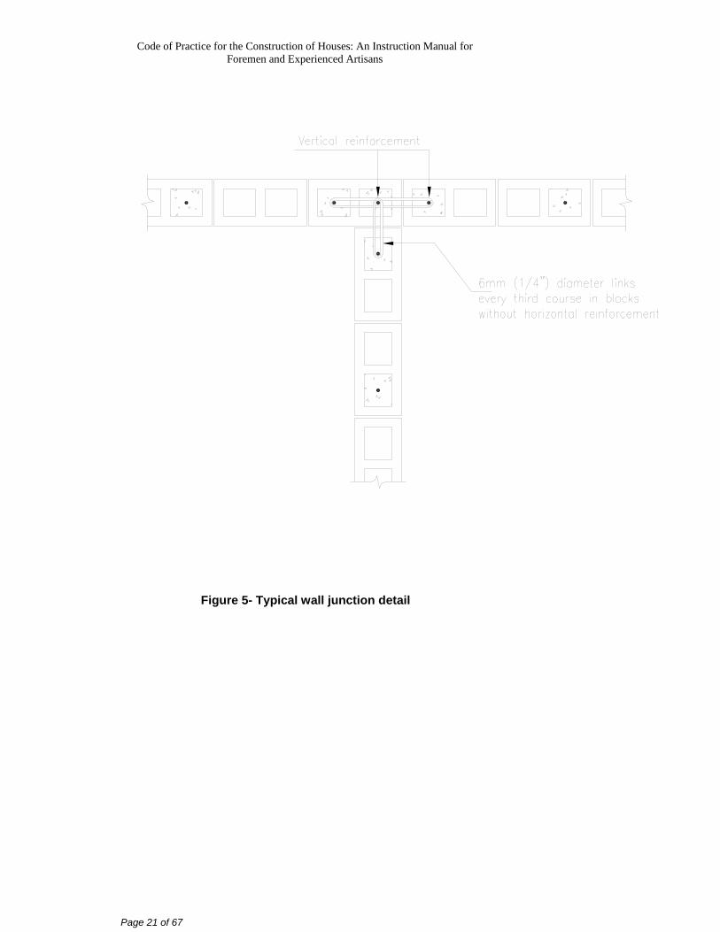
Figure 5- Typical wall junction detail
Code of Practice for the Construction of Houses: An Instruction Manual for Foremen and Experienced Artisans
Page 22 of 67
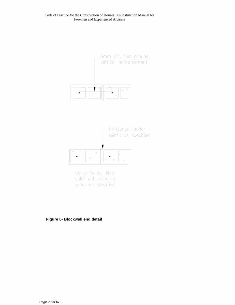
Figure 6- Blockwall end detail
Code of Practice for the Construction of Houses: An Instruction Manual for Foremen and Experienced Artisans
Page 23 of 67
Figure 7- Blockwall junction detail
Code of Practice for the Construction of Houses: An Instruction Manual for Foremen and Experienced Artisans
Page 24 of 67
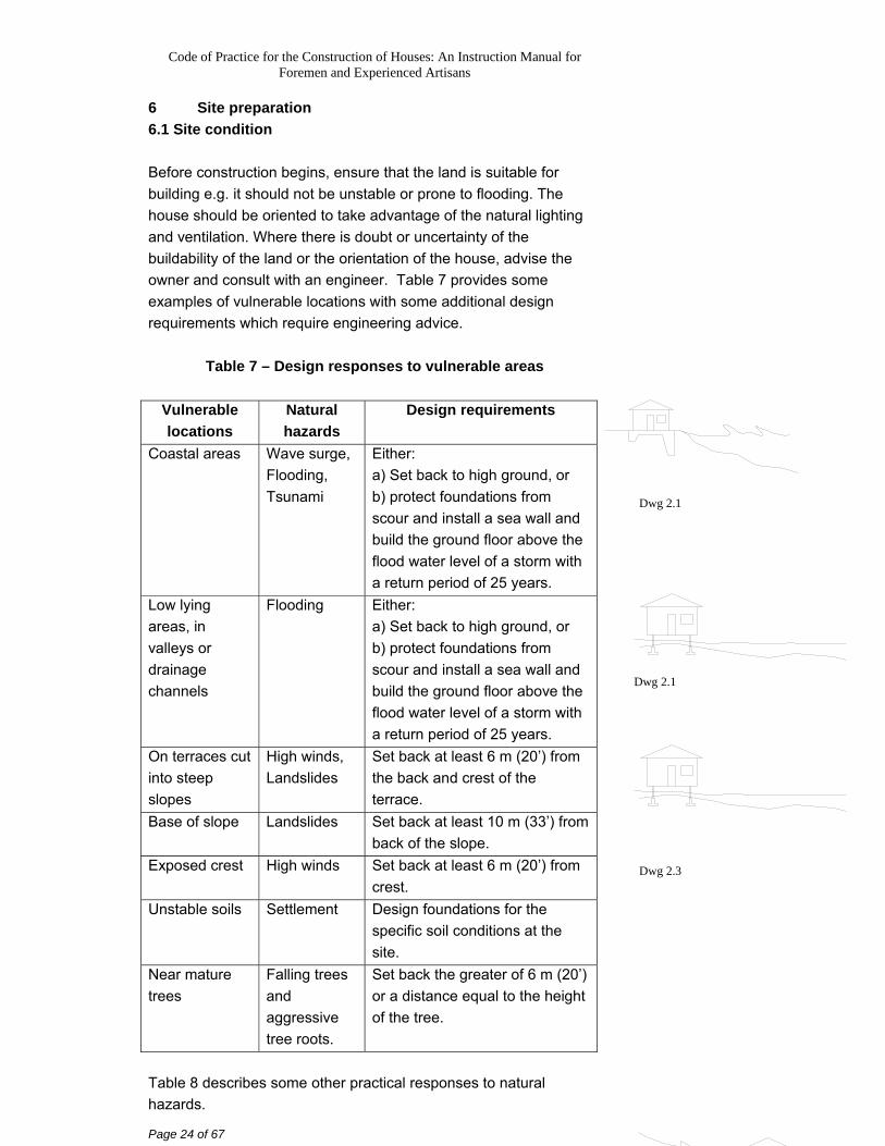
6 Site preparation 6.1 Site condition Before construction begins, ensure that the land is suitable for building e.g. it should not be unstable or prone to flooding. The house should be oriented to take advantage of the natural lighting and ventilation. Where there is doubt or uncertainty of the buildability of the land or the orientation of the house, advise the owner and consult with an engineer. Table 7 provides some examples of vulnerable locations with some additional design requirements which require engineering advice.
Table 7 – Design responses to vulnerable areas
Vulnerable locations
Natural hazards
Design requirements
Coastal areas Wave surge, Flooding, Tsunami
Either: a) Set back to high ground, or b) protect foundations from scour and install a sea wall and build the ground floor above the flood water level of a storm with a return period of 25 years.
Low lying areas, in valleys or drainage channels
Flooding Either: a) Set back to high ground, or b) protect foundations from scour and install a sea wall and build the ground floor above the flood water level of a storm with a return period of 25 years.
On terraces cut into steep slopes
High winds, Landslides
Set back at least 6 m (20’) from the back and crest of the terrace.
Base of slope Landslides Set back at least 10 m (33’) from back of the slope.
Exposed crest High winds Set back at least 6 m (20’) from crest.
Unstable soils Settlement Design foundations for the specific soil conditions at the site.
Near mature trees
Falling trees and aggressive tree roots.
Set back the greater of 6 m (20’) or a distance equal to the height of the tree.
Table 8 describes some other practical responses to natural hazards.
Dwg 2.1
Dwg 2.3
Dwg 2.1
Code of Practice for the Construction of Houses: An Instruction Manual for Foremen and Experienced Artisans
Page 25 of 67
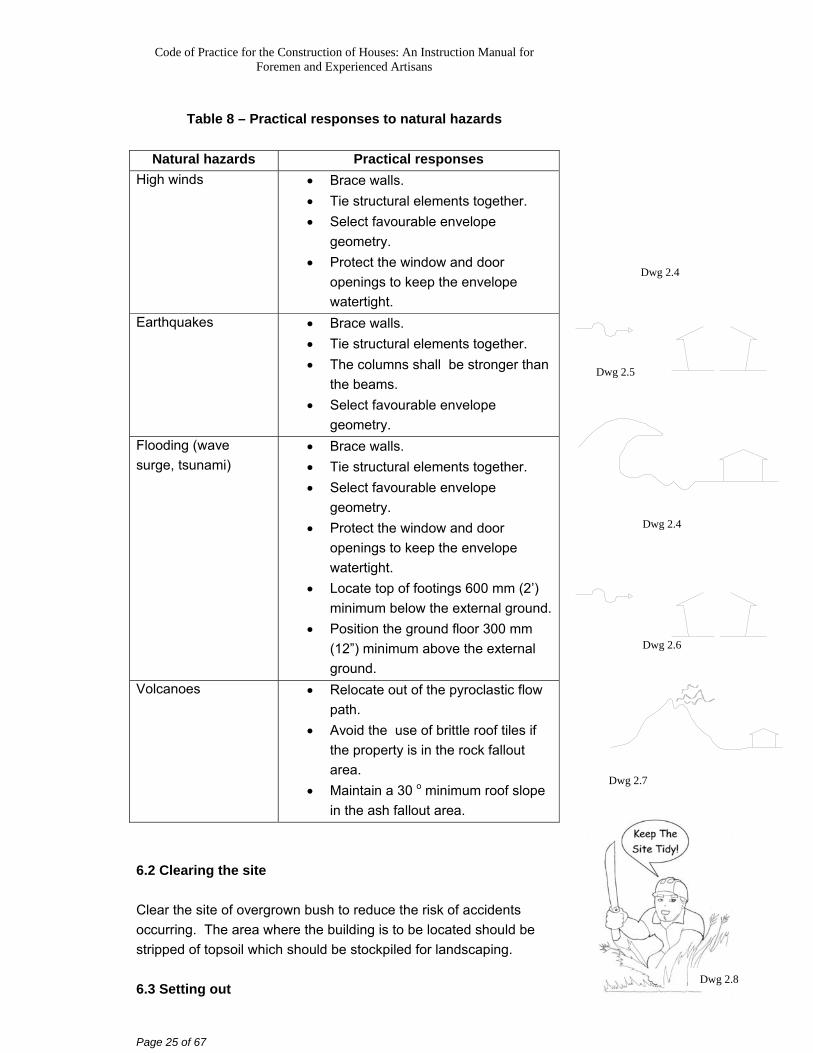
Table 8 – Practical responses to natural hazards
Natural hazards Practical responses
High winds • Brace walls. • Tie structural elements together. • Select favourable envelope
geometry. • Protect the window and door
openings to keep the envelope watertight.
Earthquakes • Brace walls. • Tie structural elements together. • The columns shall be stronger than
the beams. • Select favourable envelope
geometry. Flooding (wave surge, tsunami)
• Brace walls. • Tie structural elements together. • Select favourable envelope
geometry. • Protect the window and door
openings to keep the envelope watertight.
• Locate top of footings 600 mm (2’) minimum below the external ground.
• Position the ground floor 300 mm (12”) minimum above the external ground.
Volcanoes • Relocate out of the pyroclastic flow path.
• Avoid the use of brittle roof tiles if the property is in the rock fallout area.
• Maintain a 30 o minimum roof slope in the ash fallout area.
6.2 Clearing the site Clear the site of overgrown bush to reduce the risk of accidents occurring. The area where the building is to be located should be stripped of topsoil which should be stockpiled for landscaping. 6.3 Setting out
Dwg 2.4
Dwg 2.5
Dwg 2.6
Dwg 2.7
Dwg 2.8
Dwg 2.4
Code of Practice for the Construction of Houses: An Instruction Manual for Foremen and Experienced Artisans
Page 26 of 67
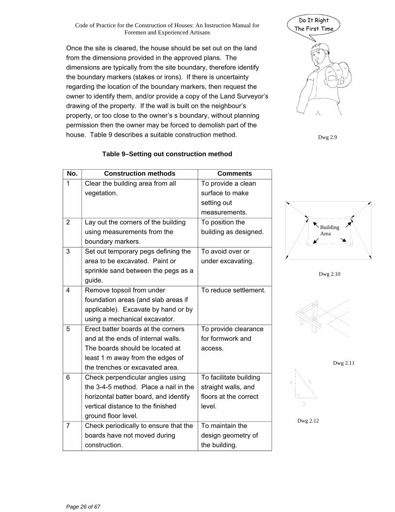
Once the site is cleared, the house should be set out on the land from the dimensions provided in the approved plans. The dimensions are typically from the site boundary, therefore identify the boundary markers (stakes or irons). If there is uncertainty regarding the location of the boundary markers, then request the owner to identify them, and/or provide a copy of the Land Surveyor’s drawing of the property. If the wall is built on the neighbour’s property, or too close to the owner’s s boundary, without planning permission then the owner may be forced to demolish part of the house. Table 9 describes a suitable construction method.
Table 9–Setting out construction method
No. Construction methods Comments 1 Clear the building area from all
vegetation. To provide a clean surface to make setting out measurements.
2 Lay out the corners of the building using measurements from the boundary markers.
To position the building as designed.
3 Set out temporary pegs defining the area to be excavated. Paint or sprinkle sand between the pegs as a guide.
To avoid over or under excavating.
4 Remove topsoil from under foundation areas (and slab areas if applicable). Excavate by hand or by using a mechanical excavator.
To reduce settlement.
5 Erect batter boards at the corners and at the ends of internal walls. The boards should be located at least 1 m away from the edges of the trenches or excavated area.
To provide clearance for formwork and access.
6 Check perpendicular angles using the 3-4-5 method. Place a nail in the horizontal batter board, and identify vertical distance to the finished ground floor level.
To facilitate building straight walls, and floors at the correct level.
7 Check periodically to ensure that the boards have not moved during construction.
To maintain the design geometry of the building.
Dwg 2.9
Dwg 2.10
Dwg 2.11
Dwg 2.12
Building Area
Code of Practice for the Construction of Houses: An Instruction Manual for Foremen and Experienced Artisans
Page 27 of 67
6.4 Access to roads Construct a temporary access road if the site is difficult to access. If a permanent access road or driveway is required, ensure that the road is accurately set out and properly constructed. Table 10 describes a suitable construction method..
Table 10 – Access road construction method No. Construction methods Comments 1 Clear the road area of all vegetation. To provide a clean
surface to make setting out measurements.
2 Lay out the centre line of the access road using measurements from the boundary markers.
To position the road as designed.
3 Offset by a minimum of 1.25 m (4’-2”).
To provide a minimum road width of 2.5 m (8’-4”).
4 Remove topsoil and any soft soil to a maximum depth of 600 mm (2’).
To reduce settlement.
5 Backfill slab area using well graded granular fill heavily compacted in layers not exceeding 150 mm (6”).
To reduce settlement.
Dwg 2.13
Code of Practice for the Construction of Houses: An Instruction Manual for Foremen and Experienced Artisans
Page 28 of 67
7 Foundations Foundations are designed to support the building and to prevent it from moving during natural hazards. The methods of constructing foundations are described in this section. An experienced engineer should be consulted in determining the appropriate level for the foundation if there is uncertainty. There are four types of foundations that are described in this section:
a) timber post; b) concrete pad; c) concrete strip; d) concrete raft.
All of the foundation types listed above, except the timber post type, require some excavation. 7.1 Excavations Table 11 describes a suitable excavation construction method.
Table 11 – Excavation construction method
No. Construction methods Comments 1 Setting out (See Table 9). To correctly position
the house on the lot. 2 Excavate either to:
a) a minimum of 600 mm to a good foundation layer (dense sand, marl, other granular material, stiff clay), or
b) rock.
To reduce settlement.
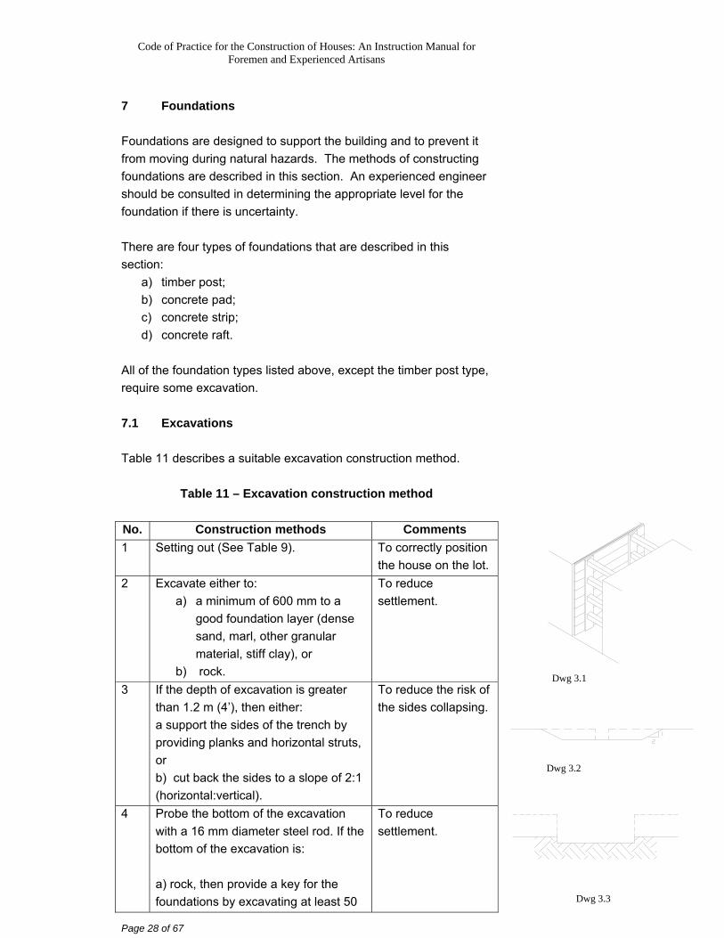
3 If the depth of excavation is greater than 1.2 m (4’), then either: a support the sides of the trench by providing planks and horizontal struts, or b) cut back the sides to a slope of 2:1 (horizontal:vertical).
To reduce the risk of the sides collapsing.
4 Probe the bottom of the excavation with a 16 mm diameter steel rod. If the bottom of the excavation is: a) rock, then provide a key for the foundations by excavating at least 50
To reduce settlement.
Dwg 3.1
Dwg 3.2
Dwg 3.3
Code of Practice for the Construction of Houses: An Instruction Manual for Foremen and Experienced Artisans
Page 29 of 67
No. Construction methods Comments mm (2”) into the rock. b) loose, then it can be compacted by ramming. c) found to have pockets of unsuitable material, then the pockets need to be removed. Deep areas and over-excavated areas can be backfilled with compacted granular material or with 1:3:6 (cement: sand: aggregate) concrete mix. d) clay or if there is uncertainty as to the type of material, then engineering advice should be sought.
7.2 Timber post foundations Timber post foundations are relatively inexpensive. Table 12 describes a suitable timber post construction method:
Table 12 – Timber post foundation construction method
No. Construction methods Comments 1 Drive 100 mmx100 mm (4”x4”)
minimum Greenheart or termite treated timber posts at least 1200 mm (4’) into the ground and to firm bearing layer. Alternatively, the post can be placed in a hole and concreted. To reduce the vulnerability to insect attack, precast concrete piles can be used.
To reduce settlement.
2 Brace the timber posts. To reduce lateral movement.
3 Termite treatment should be applied to the ground under the footings by a reputable company that will offer a minimum 5-year guarantee.
To protect the timber from termites.
7.3 Pad footings For and with a steep slope, reinforced concrete (RC) pad footings supporting RC columns and beams may be an economical solution. Table 13 describes a suitable construction method.
Code of Practice for the Construction of Houses: An Instruction Manual for Foremen and Experienced Artisans
Page 30 of 67
Table 13 – Pad footing construction method
No. Construction methods Comments 1 Excavate to good bearing layer. To reduce
settlement. 2 Termite treatment should be applied
to the ground under the footings by a reputable company that will offer a minimum 5-year guarantee.
To protect the timber from termites.
3 Place 50 mm (2”) thick sand layer or mass concrete blinding layer if the surface is uneven.
To provide a flat surface to accommodate the placement of reinforcement.
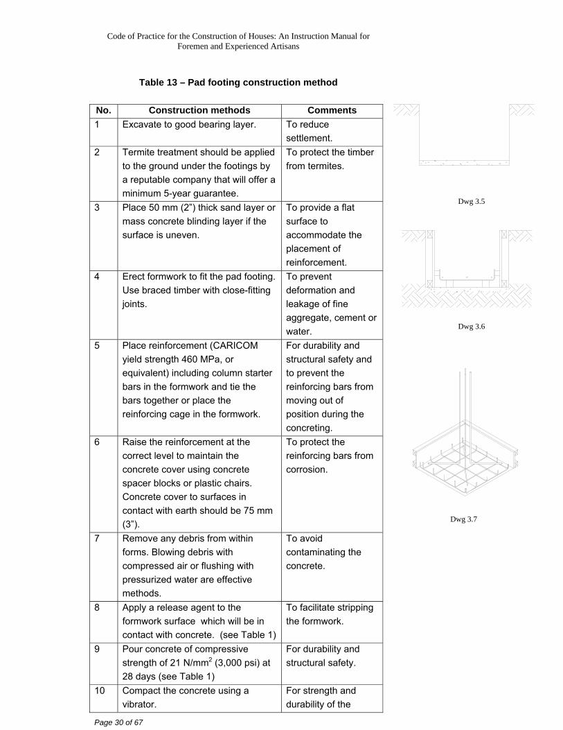
4 Erect formwork to fit the pad footing. Use braced timber with close-fitting joints.
To prevent deformation and leakage of fine aggregate, cement or water.
5 Place reinforcement (CARICOM yield strength 460 MPa, or equivalent) including column starter bars in the formwork and tie the bars together or place the reinforcing cage in the formwork.
For durability and structural safety and to prevent the reinforcing bars from moving out of position during the concreting.
6 Raise the reinforcement at the correct level to maintain the concrete cover using concrete spacer blocks or plastic chairs. Concrete cover to surfaces in contact with earth should be 75 mm (3”).
To protect the reinforcing bars from corrosion.
7 Remove any debris from within forms. Blowing debris with compressed air or flushing with pressurized water are effective methods.
To avoid contaminating the concrete.
8 Apply a release agent to the formwork surface which will be in contact with concrete. (see Table 1)
To facilitate stripping the formwork.
9 Pour concrete of compressive strength of 21 N/mm2 (3,000 psi) at 28 days (see Table 1)
For durability and structural safety.
10 Compact the concrete using a vibrator.
For strength and durability of the
Dwg 3.5
Dwg 3.6
Dwg 3.7
Code of Practice for the Construction of Houses: An Instruction Manual for Foremen and Experienced Artisans
Page 31 of 67
No. Construction methods Comments concrete.
11 Trowel finish. To provide a flat bearing surface for the walls.
12 Cure by keeping continuously wet for at least 3 days. (see Table 1)
To allow the concrete to achieve the design strength.
13 Lap column bars to starter bars and install tie-beam reinforcing bars.
To help transfer the loads.
14 Erect formwork to fit the columns and tie-beams.
To prevent deformation and leakage.
15 Pour concrete to fill the column form work, and fill half of the depth of the tie-beam form work. Compact, trowel finish, and cure the concrete.
For durability and structural safety.
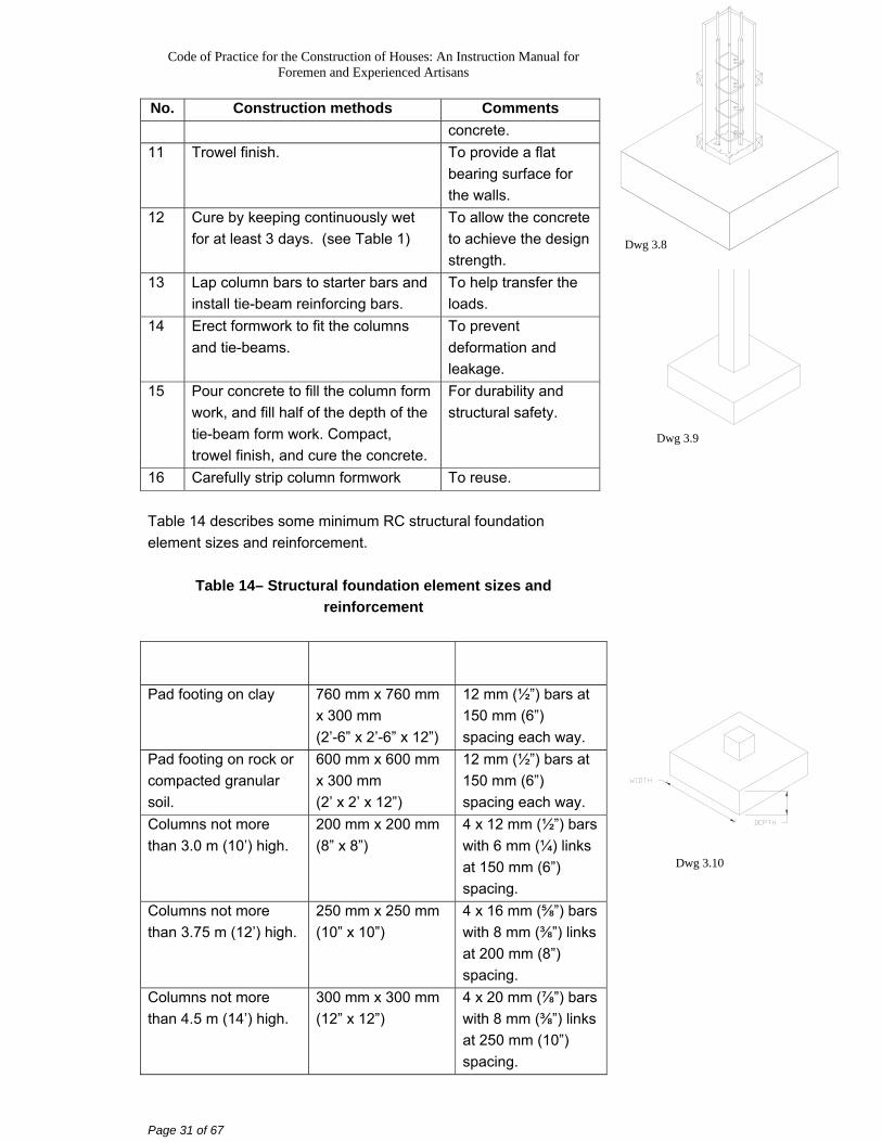
16 Carefully strip column formwork To reuse. Table 14 describes some minimum RC structural foundation element sizes and reinforcement.
Table 14– Structural foundation element sizes and reinforcement
Pad footing on clay 760 mm x 760 mm x 300 mm (2’-6” x 2’-6” x 12”)
12 mm (½”) bars at 150 mm (6”) spacing each way.
Pad footing on rock or compacted granular soil.
600 mm x 600 mm x 300 mm (2’ x 2’ x 12”)
12 mm (½”) bars at 150 mm (6”) spacing each way.
Columns not more than 3.0 m (10’) high.
200 mm x 200 mm (8” x 8”)
4 x 12 mm (½”) bars with 6 mm (¼) links at 150 mm (6”) spacing.
Columns not more than 3.75 m (12’) high.
250 mm x 250 mm (10” x 10”)
4 x 16 mm (⅝”) bars with 8 mm (⅜”) links at 200 mm (8”) spacing.
Columns not more than 4.5 m (14’) high.
300 mm x 300 mm (12” x 12”)
4 x 20 mm (⅞”) bars with 8 mm (⅜”) links at 250 mm (10”) spacing.
Dwg 3.8
Dwg 3.9
Dwg 3.10
Code of Practice for the Construction of Houses: An Instruction Manual for Foremen and Experienced Artisans
Page 32 of 67
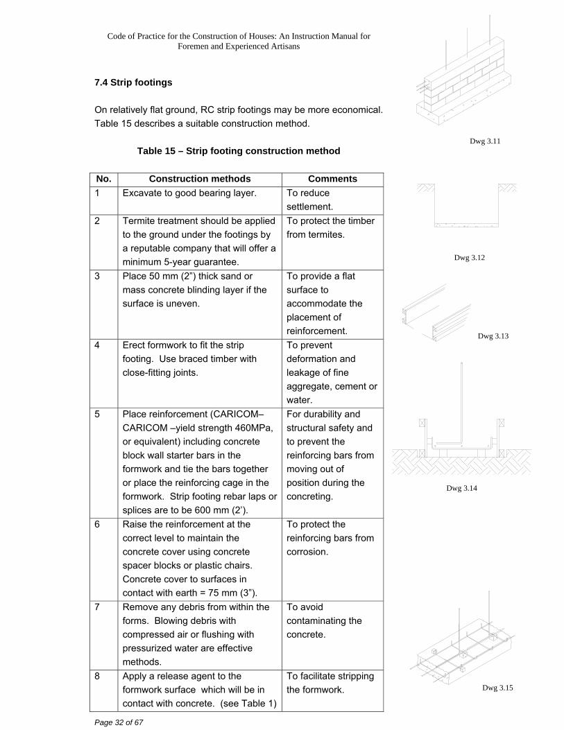
7.4 Strip footings On relatively flat ground, RC strip footings may be more economical. Table 15 describes a suitable construction method.
Table 15 – Strip footing construction method
No. Construction methods Comments 1 Excavate to good bearing layer. To reduce
settlement. 2 Termite treatment should be applied
to the ground under the footings by a reputable company that will offer a minimum 5-year guarantee.
To protect the timber from termites.
3 Place 50 mm (2”) thick sand or mass concrete blinding layer if the surface is uneven.
To provide a flat surface to accommodate the placement of reinforcement.
4 Erect formwork to fit the strip footing. Use braced timber with close-fitting joints.
To prevent deformation and leakage of fine aggregate, cement or water.
5 Place reinforcement (CARICOM–CARICOM –yield strength 460MPa, or equivalent) including concrete block wall starter bars in the formwork and tie the bars together or place the reinforcing cage in the formwork. Strip footing rebar laps or splices are to be 600 mm (2’).
For durability and structural safety and to prevent the reinforcing bars from moving out of position during the concreting.
6 Raise the reinforcement at the correct level to maintain the concrete cover using concrete spacer blocks or plastic chairs. Concrete cover to surfaces in contact with earth = 75 mm (3”).
To protect the reinforcing bars from corrosion.
7 Remove any debris from within the forms. Blowing debris with compressed air or flushing with pressurized water are effective methods.
To avoid contaminating the concrete.
8 Apply a release agent to the formwork surface which will be in contact with concrete. (see Table 1)
To facilitate stripping the formwork.
Dwg 3.11
Dwg 3.12
Dwg 3.13
Dwg 3.14
Dwg 3.15
Code of Practice for the Construction of Houses: An Instruction Manual for Foremen and Experienced Artisans
Page 33 of 67
No. Construction methods Comments 9 Pour concrete of compressive
strength of 21 N/mm2 (3,000 psi) at 28 days (see Table 1)
For durability and structural safety.
10 Compact the concrete using a vibrator.
For strength and durability of the concrete.
11 Trowel finish. To provide a flat bearing surface for the walls.
12 Cure by keeping continuously wet for at least 3 days. (see Table 1)
To allow the concrete to achieve the design strength.
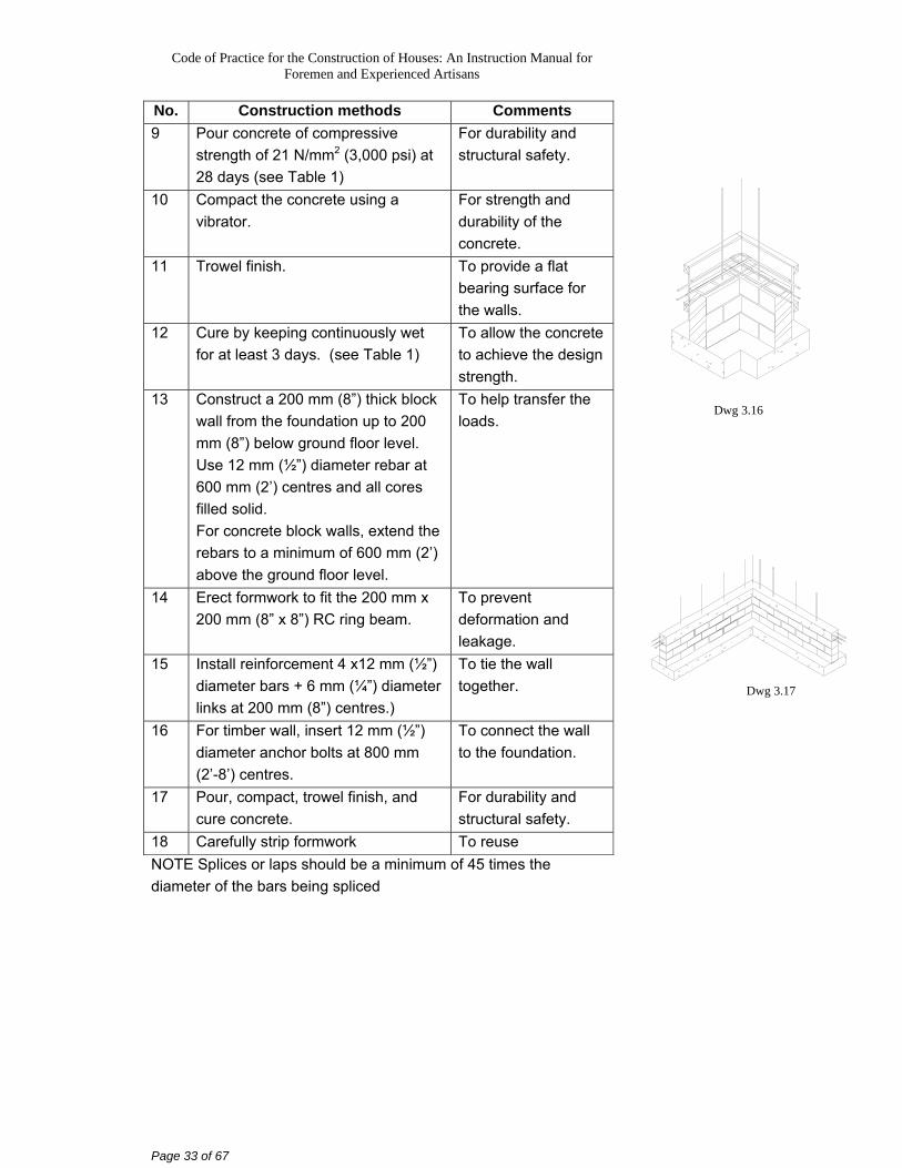
13 Construct a 200 mm (8”) thick block wall from the foundation up to 200 mm (8”) below ground floor level. Use 12 mm (½”) diameter rebar at 600 mm (2’) centres and all cores filled solid. For concrete block walls, extend the rebars to a minimum of 600 mm (2’) above the ground floor level.
To help transfer the loads.
14 Erect formwork to fit the 200 mm x 200 mm (8” x 8”) RC ring beam.
To prevent deformation and leakage.
15 Install reinforcement 4 x12 mm (½”) diameter bars + 6 mm (¼”) diameter links at 200 mm (8”) centres.)
To tie the wall together.
16 For timber wall, insert 12 mm (½”) diameter anchor bolts at 800 mm (2’-8’) centres.
To connect the wall to the foundation.
17 Pour, compact, trowel finish, and cure concrete.
For durability and structural safety.
18 Carefully strip formwork To reuse NOTE Splices or laps should be a minimum of 45 times the diameter of the bars being spliced
Dwg 3.16
Dwg 3.17
Code of Practice for the Construction of Houses: An Instruction Manual for Foremen and Experienced Artisans
Page 34 of 67
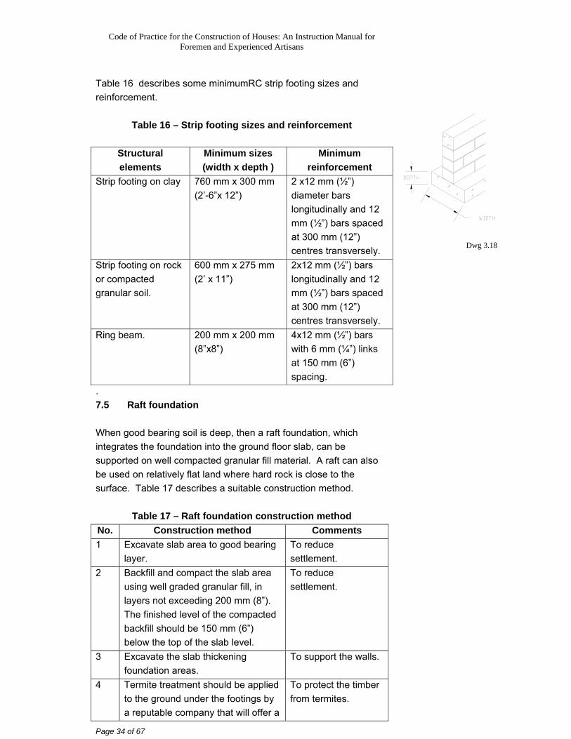
Table 16 describes some minimumRC strip footing sizes and reinforcement.
Table 16 – Strip footing sizes and reinforcement
Structural elements
Minimum sizes (width x depth )
Minimum reinforcement
Strip footing on clay 760 mm x 300 mm (2’-6”x 12”)
2 x12 mm (½”) diameter bars longitudinally and 12 mm (½”) bars spaced at 300 mm (12”) centres transversely.
Strip footing on rock or compacted granular soil.
600 mm x 275 mm (2’ x 11”)
2x12 mm (½”) bars longitudinally and 12 mm (½”) bars spaced at 300 mm (12”) centres transversely.
Ring beam. 200 mm x 200 mm (8”x8”)
4x12 mm (½”) bars with 6 mm (¼”) links at 150 mm (6”) spacing.
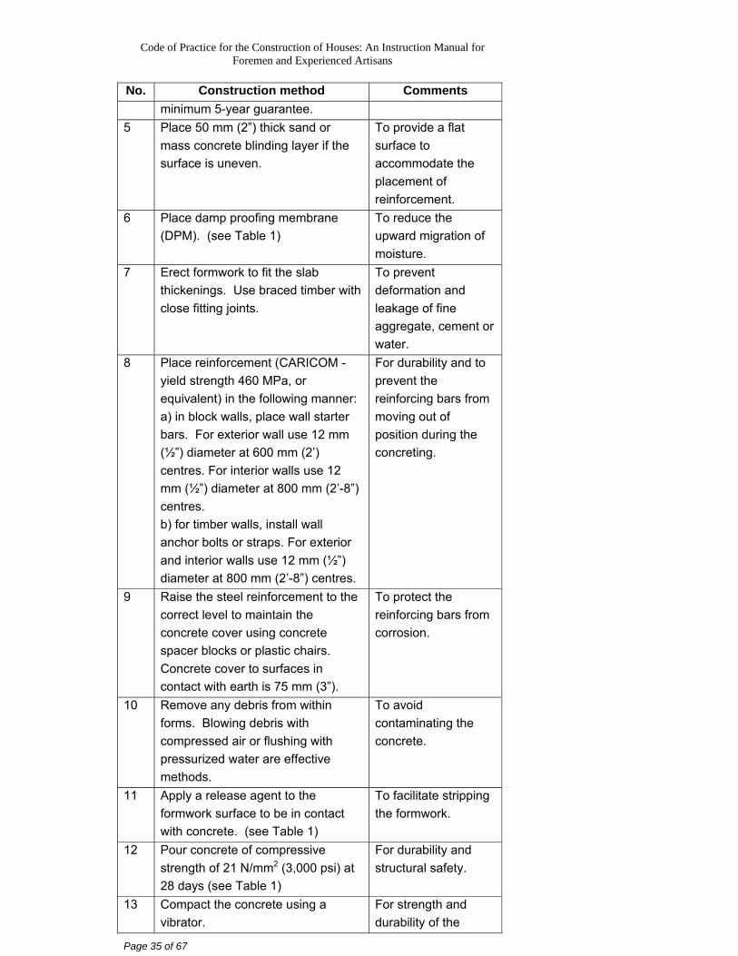
. 7.5 Raft foundation When good bearing soil is deep, then a raft foundation, which integrates the foundation into the ground floor slab, can be supported on well compacted granular fill material. A raft can also be used on relatively flat land where hard rock is close to the surface. Table 17 describes a suitable construction method.
Table 17 – Raft foundation construction method No. Construction method Comments 1 Excavate slab area to good bearing
layer. To reduce settlement.
2 Backfill and compact the slab area using well graded granular fill, in layers not exceeding 200 mm (8”). The finished level of the compacted backfill should be 150 mm (6”) below the top of the slab level.
To reduce settlement.
3 Excavate the slab thickening foundation areas.
To support the walls.
4 Termite treatment should be applied to the ground under the footings by a reputable company that will offer a
To protect the timber from termites.
Dwg 3.18
Code of Practice for the Construction of Houses: An Instruction Manual for Foremen and Experienced Artisans
Page 35 of 67
No. Construction method Comments minimum 5-year guarantee.
5 Place 50 mm (2”) thick sand or mass concrete blinding layer if the surface is uneven.
To provide a flat surface to accommodate the placement of reinforcement.
6 Place damp proofing membrane (DPM). (see Table 1)
To reduce the upward migration of moisture.
7 Erect formwork to fit the slab thickenings. Use braced timber with close fitting joints.
To prevent deformation and leakage of fine aggregate, cement or water.
8 Place reinforcement (CARICOM - yield strength 460 MPa, or equivalent) in the following manner: a) in block walls, place wall starter bars. For exterior wall use 12 mm (½”) diameter at 600 mm (2’) centres. For interior walls use 12 mm (½”) diameter at 800 mm (2’-8”) centres. b) for timber walls, install wall anchor bolts or straps. For exterior and interior walls use 12 mm (½”) diameter at 800 mm (2’-8”) centres.
For durability and to prevent the reinforcing bars from moving out of position during the concreting.
9 Raise the steel reinforcement to the correct level to maintain the concrete cover using concrete spacer blocks or plastic chairs. Concrete cover to surfaces in contact with earth is 75 mm (3”).
To protect the reinforcing bars from corrosion.
10 Remove any debris from within forms. Blowing debris with compressed air or flushing with pressurized water are effective methods.
To avoid contaminating the concrete.
11 Apply a release agent to the formwork surface to be in contact with concrete. (see Table 1)
To facilitate stripping the formwork.
12 Pour concrete of compressive strength of 21 N/mm2 (3,000 psi) at 28 days (see Table 1)
For durability and structural safety.
13 Compact the concrete using a vibrator.
For strength and durability of the
Code of Practice for the Construction of Houses: An Instruction Manual for Foremen and Experienced Artisans
Page 36 of 67
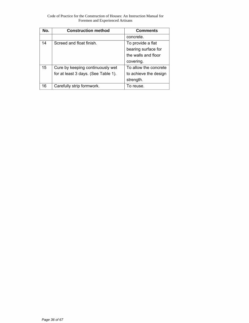
No. Construction method Comments concrete.
14 Screed and float finish. To provide a flat bearing surface for the walls and floor covering.
15 Cure by keeping continuously wet for at least 3 days. (See Table 1).
To allow the concrete to achieve the design strength.
16 Carefully strip formwork. To reuse.
Code of Practice for the Construction of Houses: An Instruction Manual for Foremen and Experienced Artisans
Page 37 of 67
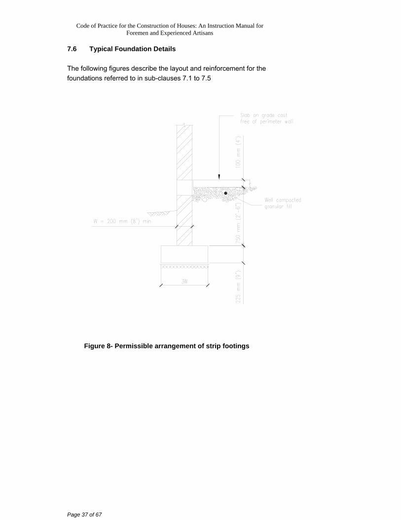
7.6 Typical Foundation Details The following figures describe the layout and reinforcement for the foundations referred to in sub-clauses 7.1 to 7.5
Figure 8- Permissible arrangement of strip footings
Code of Practice for the Construction of Houses: An Instruction Manual for Foremen and Experienced Artisans
Page 38 of 67
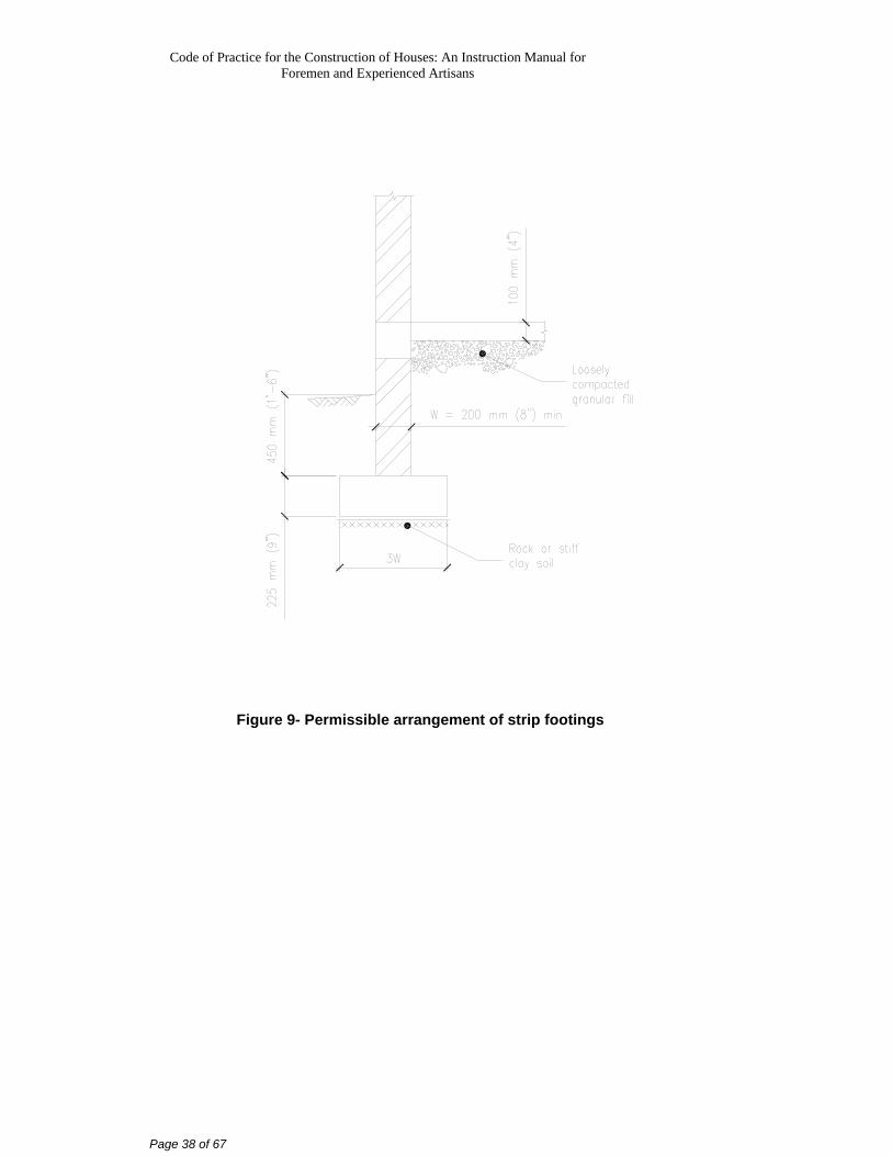
Figure 9- Permissible arrangement of strip footings
Code of Practice for the Construction of Houses: An Instruction Manual for Foremen and Experienced Artisans
Page 39 of 67
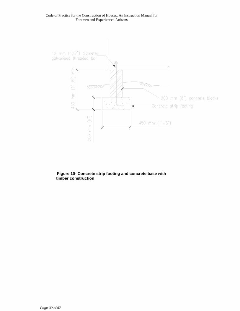
Figure 10- Concrete strip footing and concrete base with timber construction
Code of Practice for the Construction of Houses: An Instruction Manual for Foremen and Experienced Artisans
Page 40 of 67
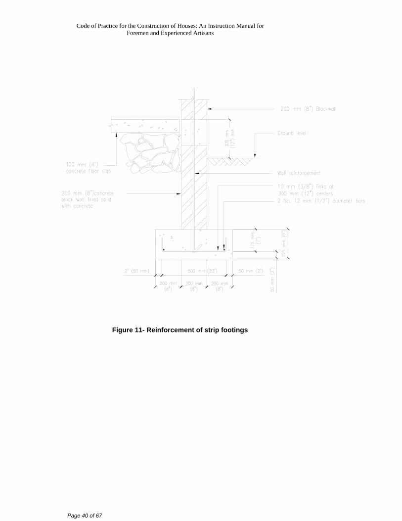
Figure 11- Reinforcement of strip footings
Code of Practice for the Construction of Houses: An Instruction Manual for Foremen and Experienced Artisans
Page 41 of 67
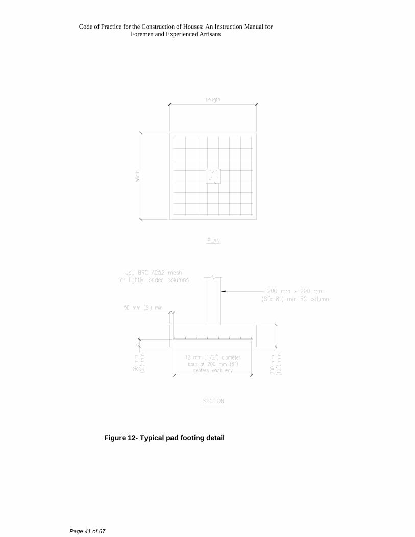
Figure 12- Typical pad footing detail
Code of Practice for the Construction of Houses: An Instruction Manual for Foremen and Experienced Artisans
Page 42 of 67
8. Floors The floor is used to support the floor loads and to transmit them to the foundations. Four types are described below:
a) Raft foundation with integral ground floor slab supported on fill (sub-clause 7.5)
b) Reinforced Concrete (RC) ground floor slab supported on strip footings.
c) Suspended RC floor slab supported on pad footings. d) Suspended timber floor supported on RC beams.
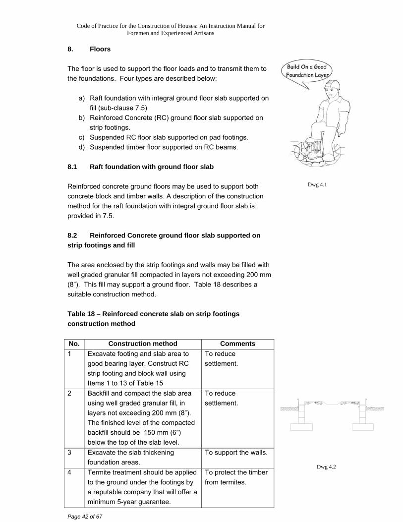
8.1 Raft foundation with ground floor slab Reinforced concrete ground floors may be used to support both concrete block and timber walls. A description of the construction method for the raft foundation with integral ground floor slab is provided in 7.5. 8.2 Reinforced Concrete ground floor slab supported on strip footings and fill The area enclosed by the strip footings and walls may be filled with well graded granular fill compacted in layers not exceeding 200 mm (8”). This fill may support a ground floor. Table 18 describes a suitable construction method. Table 18 – Reinforced concrete slab on strip footings construction method No. Construction method Comments 1 Excavate footing and slab area to
good bearing layer. Construct RC strip footing and block wall using Items 1 to 13 of Table 15
To reduce settlement.
2 Backfill and compact the slab area using well graded granular fill, in layers not exceeding 200 mm (8”). The finished level of the compacted backfill should be 150 mm (6”) below the top of the slab level.
To reduce settlement.
3 Excavate the slab thickening foundation areas.
To support the walls.
4 Termite treatment should be applied to the ground under the footings by a reputable company that will offer a minimum 5-year guarantee.
To protect the timber from termites.
Dwg 4.1
Dwg 4.2
Code of Practice for the Construction of Houses: An Instruction Manual for Foremen and Experienced Artisans
Page 43 of 67
No. Construction method Comments 5 Place 50 mm (2”) thick sand or
mass concrete blinding layer if the surface is uneven.
To provide a flat surface to accommodate the placement of reinforcement.
6 Place damp proofing membrane (DPM). (see Table 1)
To reduce the upward migration of moisture.
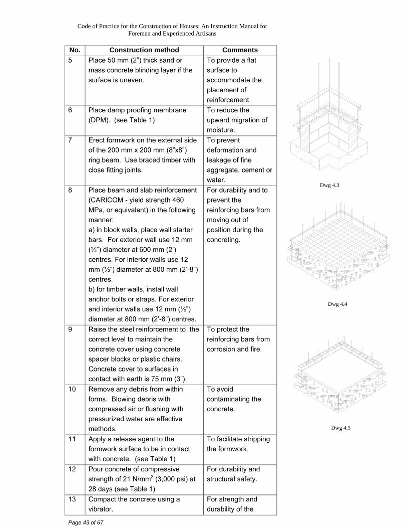
7 Erect formwork on the external side of the 200 mm x 200 mm (8”x8”) ring beam. Use braced timber with close fitting joints.
To prevent deformation and leakage of fine aggregate, cement or water.
8 Place beam and slab reinforcement (CARICOM - yield strength 460 MPa, or equivalent) in the following manner: a) in block walls, place wall starter bars. For exterior wall use 12 mm (½”) diameter at 600 mm (2’) centres. For interior walls use 12 mm (½”) diameter at 800 mm (2’-8”) centres. b) for timber walls, install wall anchor bolts or straps. For exterior and interior walls use 12 mm (½”) diameter at 800 mm (2’-8”) centres.
For durability and to prevent the reinforcing bars from moving out of position during the concreting.
9 Raise the steel reinforcement to the correct level to maintain the concrete cover using concrete spacer blocks or plastic chairs. Concrete cover to surfaces in contact with earth is 75 mm (3”).
To protect the reinforcing bars from corrosion and fire.
10 Remove any debris from within forms. Blowing debris with compressed air or flushing with pressurized water are effective methods.
To avoid contaminating the concrete.
11 Apply a release agent to the formwork surface to be in contact with concrete. (see Table 1)
To facilitate stripping the formwork.
12 Pour concrete of compressive strength of 21 N/mm2 (3,000 psi) at 28 days (see Table 1)
For durability and structural safety.
13 Compact the concrete using a vibrator.
For strength and durability of the
Dwg 4.3
Dwg 4.4
Dwg 4.5
Code of Practice for the Construction of Houses: An Instruction Manual for Foremen and Experienced Artisans
Page 44 of 67
No. Construction method Comments concrete.
14 Screed and float finish. To provide a flat bearing surface for the walls and floor covering.
15 Cure by keeping continuously wet for at least 3 days. (see Table 1).
To allow the concrete to achieve the design strength.
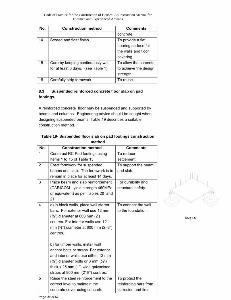
16 Carefully strip formwork. To reuse. 8.3 Suspended reinforced concrete floor slab on pad footings. A reinforced concrete floor may be suspended and supported by beams and columns. Engineering advice should be sought when designing suspended beams. Table 19 describes a suitable construction method.
Table 19- Suspended floor slab on pad footings construction method
No. Construction method Comments 1 Construct RC Pad footings using
Items 1 to 15 of Table 13. To reduce settlement.
2 Erect formwork for suspended beams and slab. The formwork is to remain in place for at least 14 days.
To support the beam and slab.
3 Place beam and slab reinforcement (CARICOM - yield strength 460MPa, or equivalent) as per Tables 20 and 21
For durability and structural safety.
4 a) in block walls, place wall starter bars. For exterior wall use 12 mm (½”) diameter at 600 mm (2’) centres. For interior walls use 12 mm (½”) diameter at 800 mm (2’-8”) centres. b) for timber walls, install wall anchor bolts or straps. For exterior and interior walls use either 12 mm (½”) diameter bolts or 3 mm (⅛”) thick x 25 mm (1”) wide galvanised straps at 800 mm (2’-8”) centres.
To connect the wall to the foundation.
5 Raise the steel reinforcement to the correct level to maintain the concrete cover using concrete
To protect the reinforcing bars from corrosion and fire.
Dwg 4.6
Code of Practice for the Construction of Houses: An Instruction Manual for Foremen and Experienced Artisans
Page 45 of 67
No. Construction method Comments spacer blocks or plastic chairs.
6 Remove any debris from within forms. Blowing debris with compressed air or flushing with pressurised water are effective methods.
To avoid contaminating the concrete.
7 Apply a release agent to the formwork surface to be in contact with concrete. (see Table 1)
To facilitate stripping the formwork.
8 Pour concrete of compressive strength of 21 N/mm2 (3,000 psi) at 28 days, in beam and slab formwork (see Table 1)
For durability and structural safety.
9 Compact the concrete using a vibrator.
For strength and durability of the concrete.
10 Screed and float finish. To provide a flat bearing surface for the walls and floor covering.
11 Cure by keeping continuously wet for at least 3 days. (see Table 1)
To allow the concrete to achieve the design strength.
12 Carefully strip formwork To reuse.
Code of Practice for the Construction of Houses: An Instruction Manual for Foremen and Experienced Artisans
Page 46 of 67
Table 20 provides the minimum thickness and reinforcement amounts for one way spanning RC slabs of different spans. Table 20 – Suspended reinforced concrete slab depths and reinforcement
Span Slab thickness Bottom reinforcement 3.0m (10’) 125 mm (5”) 12 mm (½”) diameter bars at 200
mm (8”) centres. 3.7m (12’) 150 mm (6”) 12 mm (½”) diameter bars at 175
mm (7”) centres 4.3m (14’) 175 mm (7”) 12 mm (½”) diameter bars at 150
mm (6”) centres 4.9m (16’) 200 mm (8”) 12 mm (½”) diameter bars at 150
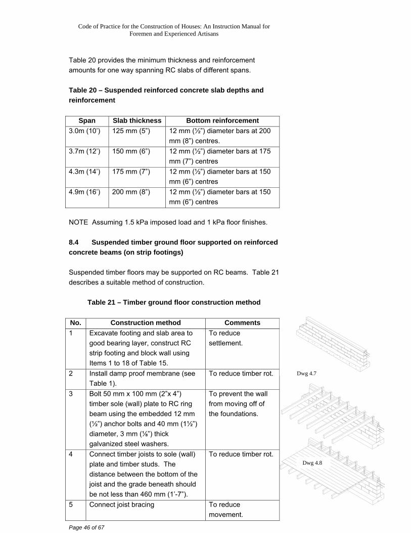
mm (6”) centres NOTE Assuming 1.5 kPa imposed load and 1 kPa floor finishes. 8.4 Suspended timber ground floor supported on reinforced concrete beams (on strip footings) Suspended timber floors may be supported on RC beams. Table 21 describes a suitable method of construction.
Table 21 – Timber ground floor construction method
No. Construction method Comments 1 Excavate footing and slab area to
good bearing layer, construct RC strip footing and block wall using Items 1 to 18 of Table 15.
To reduce settlement.
2 Install damp proof membrane (see Table 1).
To reduce timber rot.
3 Bolt 50 mm x 100 mm (2”x 4”) timber sole (wall) plate to RC ring beam using the embedded 12 mm (½”) anchor bolts and 40 mm (1½”) diameter, 3 mm (⅛”) thick galvanized steel washers.
To prevent the wall from moving off of the foundations.
4 Connect timber joists to sole (wall) plate and timber studs. The distance between the bottom of the joist and the grade beneath should be not less than 460 mm (1’-7”).
To reduce timber rot.
5 Connect joist bracing To reduce movement.
Dwg 4.7
Dwg 4.8
Code of Practice for the Construction of Houses: An Instruction Manual for Foremen and Experienced Artisans
Page 47 of 67
No. Construction method Comments 6 Connect 25 mm (1”) thick tongue
and groove floor to joists To support floor loads.
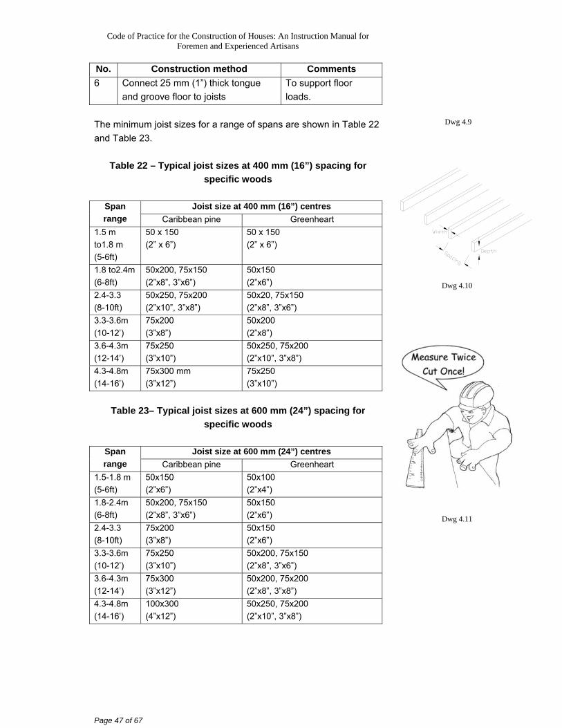
The minimum joist sizes for a range of spans are shown in Table 22 and Table 23.
Table 22 – Typical joist sizes at 400 mm (16”) spacing for specific woods
Joist size at 400 mm (16”) centres Span
range Caribbean pine Greenheart 1.5 m to1.8 m (5-6ft)
50 x 150 (2” x 6”)
50 x 150 (2” x 6”)
1.8 to2.4m (6-8ft)
50x200, 75x150 (2”x8”, 3”x6”)
50x150 (2”x6”)
2.4-3.3 (8-10ft)
50x250, 75x200 (2”x10”, 3”x8”)
50x20, 75x150 (2”x8”, 3”x6”)
3.3-3.6m (10-12’)
75x200 (3”x8”)
50x200 (2”x8”)
3.6-4.3m (12-14’)
75x250 (3”x10”)
50x250, 75x200 (2”x10”, 3”x8”)
4.3-4.8m (14-16’)
75x300 mm (3”x12”)
75x250 (3”x10”)
Table 23– Typical joist sizes at 600 mm (24”) spacing for
specific woods
Joist size at 600 mm (24”) centres Span range Caribbean pine Greenheart
1.5-1.8 m (5-6ft)
50x150 (2”x6”)
50x100 (2”x4”)
1.8-2.4m (6-8ft)
50x200, 75x150 (2”x8”, 3”x6”)
50x150 (2”x6”)
2.4-3.3 (8-10ft)
75x200 (3”x8”)
50x150 (2”x6”)
3.3-3.6m (10-12’)
75x250 (3”x10”)
50x200, 75x150 (2”x8”, 3”x6”)
3.6-4.3m (12-14’)
75x300 (3”x12”)
50x200, 75x200 (2”x8”, 3”x8”)
4.3-4.8m (14-16’)
100x300 (4”x12”)
50x250, 75x200 (2”x10”, 3”x8”)
Dwg 4.9
Dwg 4.10
Dwg 4.11
Code of Practice for the Construction of Houses: An Instruction Manual for Foremen and Experienced Artisans
Page 48 of 67
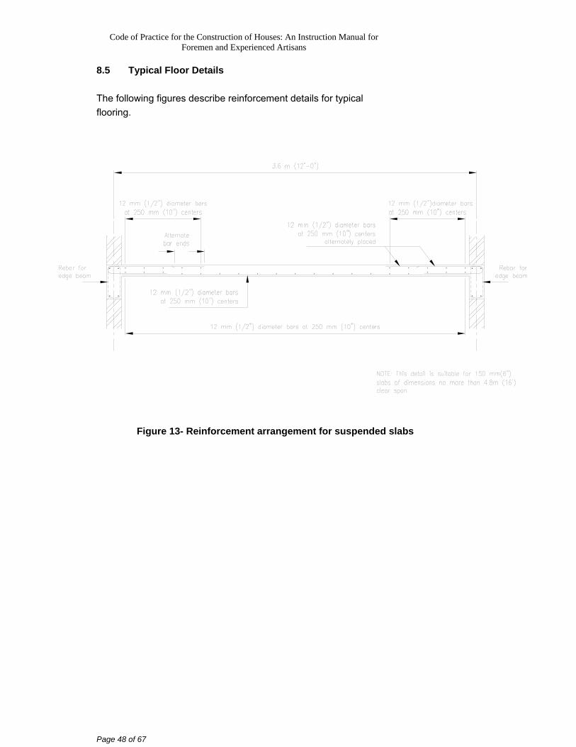
8.5 Typical Floor Details The following figures describe reinforcement details for typical flooring.
Figure 13- Reinforcement arrangement for suspended slabs
Code of Practice for the Construction of Houses: An Instruction Manual for Foremen and Experienced Artisans
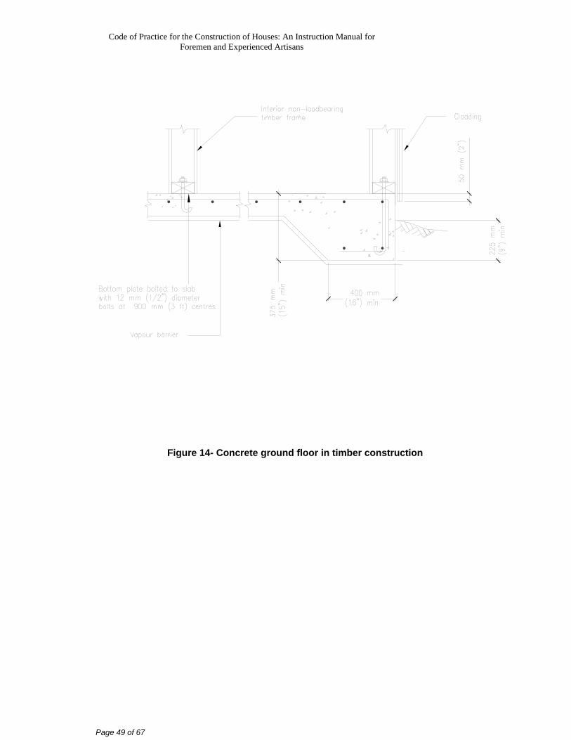
Page 49 of 67
Figure 14- Concrete ground floor in timber construction
Code of Practice for the Construction of Houses: An Instruction Manual for Foremen and Experienced Artisans
Page 50 of 67
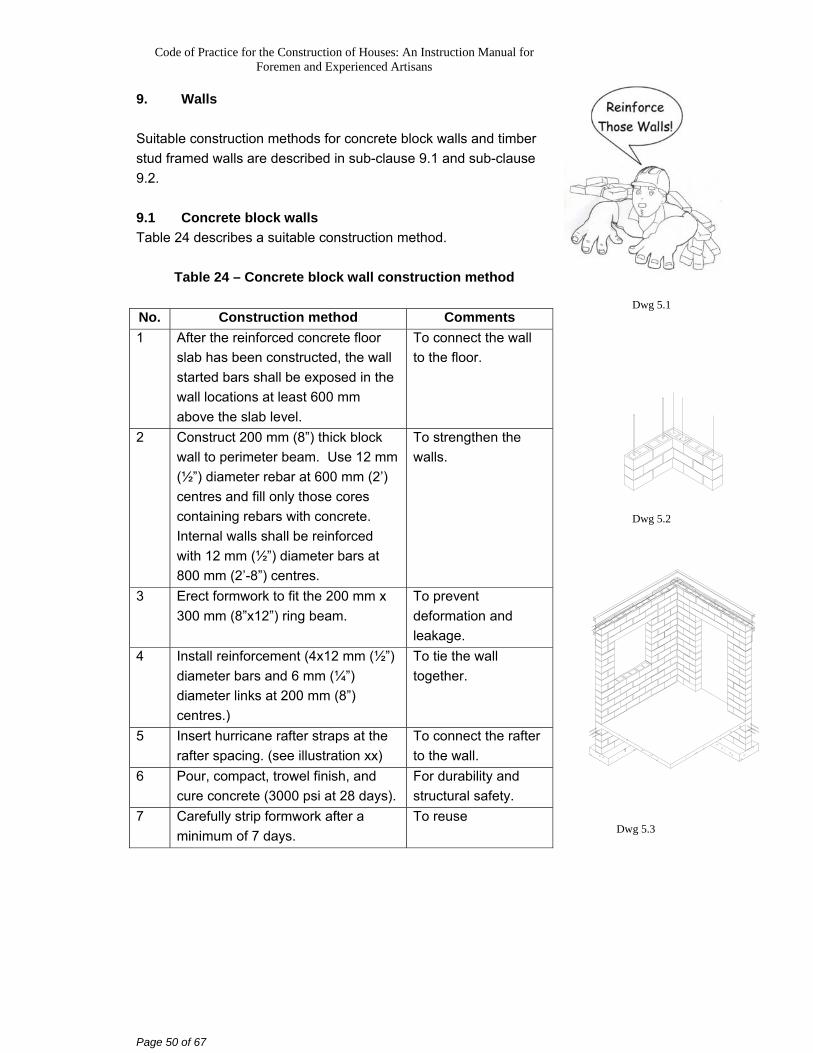
9. Walls Suitable construction methods for concrete block walls and timber stud framed walls are described in sub-clause 9.1 and sub-clause 9.2. 9.1 Concrete block walls Table 24 describes a suitable construction method.
Table 24 – Concrete block wall construction method
No. Construction method Comments 1 After the reinforced concrete floor
slab has been constructed, the wall started bars shall be exposed in the wall locations at least 600 mm above the slab level.
To connect the wall to the floor.
2 Construct 200 mm (8”) thick block wall to perimeter beam. Use 12 mm (½”) diameter rebar at 600 mm (2’) centres and fill only those cores containing rebars with concrete. Internal walls shall be reinforced with 12 mm (½”) diameter bars at 800 mm (2’-8”) centres.
To strengthen the walls.
3 Erect formwork to fit the 200 mm x 300 mm (8”x12”) ring beam.
To prevent deformation and leakage.
4 Install reinforcement (4x12 mm (½”) diameter bars and 6 mm (¼”) diameter links at 200 mm (8”) centres.)
To tie the wall together.
5 Insert hurricane rafter straps at the rafter spacing. (see illustration xx)
To connect the rafter to the wall.
6 Pour, compact, trowel finish, and cure concrete (3000 psi at 28 days).
For durability and structural safety.
7 Carefully strip formwork after a minimum of 7 days.
To reuse
Dwg 5.1
Dwg 5.2
Dwg 5.3
Code of Practice for the Construction of Houses: An Instruction Manual for Foremen and Experienced Artisans
Page 51 of 67
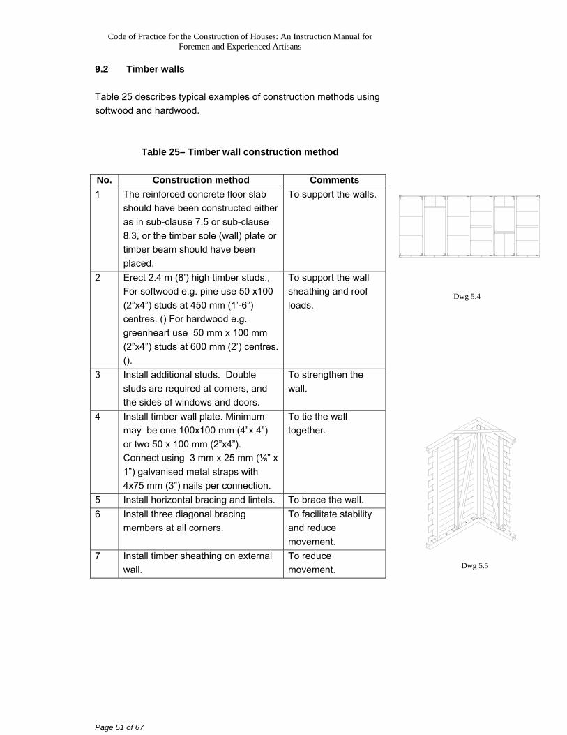
9.2 Timber walls Table 25 describes typical examples of construction methods using softwood and hardwood.
Table 25– Timber wall construction method
No. Construction method Comments 1 The reinforced concrete floor slab
should have been constructed either as in sub-clause 7.5 or sub-clause 8.3, or the timber sole (wall) plate or timber beam should have been placed.
To support the walls.
2 Erect 2.4 m (8’) high timber studs., For softwood e.g. pine use 50 x100 (2”x4”) studs at 450 mm (1’-6”) centres. () For hardwood e.g. greenheart use 50 mm x 100 mm (2”x4”) studs at 600 mm (2’) centres. ().
To support the wall sheathing and roof loads.
3 Install additional studs. Double studs are required at corners, and the sides of windows and doors.
To strengthen the wall.
4 Install timber wall plate. Minimum may be one 100x100 mm (4”x 4”) or two 50 x 100 mm (2”x4”). Connect using 3 mm x 25 mm (⅛” x 1”) galvanised metal straps with 4x75 mm (3”) nails per connection.
To tie the wall together.
5 Install horizontal bracing and lintels. To brace the wall. 6 Install three diagonal bracing
members at all corners. To facilitate stability and reduce movement.
7 Install timber sheathing on external wall.
To reduce movement.
Dwg 5.4
Dwg 5.5
Code of Practice for the Construction of Houses: An Instruction Manual for Foremen and Experienced Artisans
Page 52 of 67
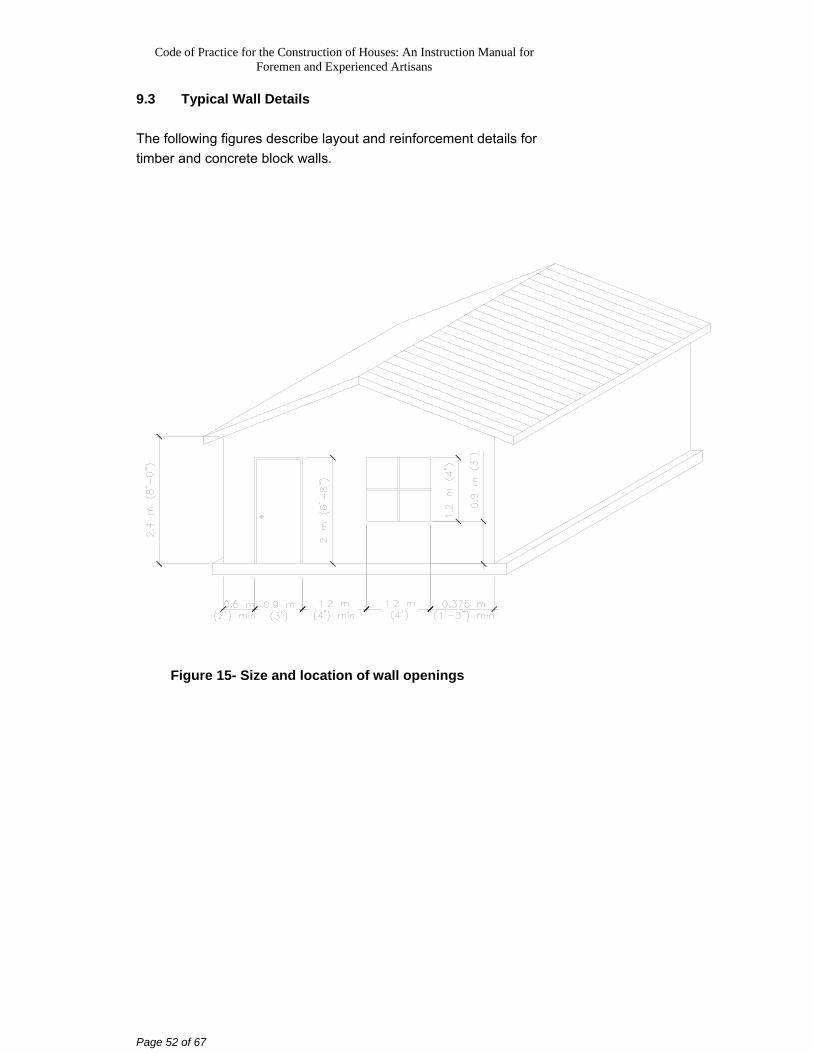
9.3 Typical Wall Details The following figures describe layout and reinforcement details for timber and concrete block walls.
Figure 15- Size and location of wall openings
Code of Practice for the Construction of Houses: An Instruction Manual for Foremen and Experienced Artisans
Page 53 of 67
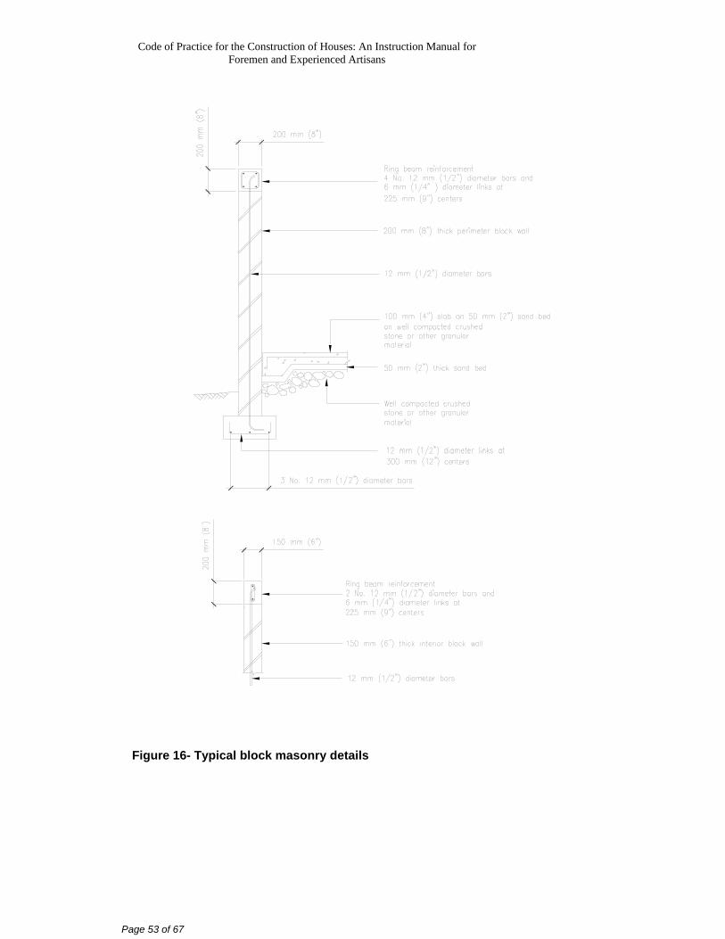
Figure 16- Typical block masonry details
Code of Practice for the Construction of Houses: An Instruction Manual for Foremen and Experienced Artisans
Page 54 of 67
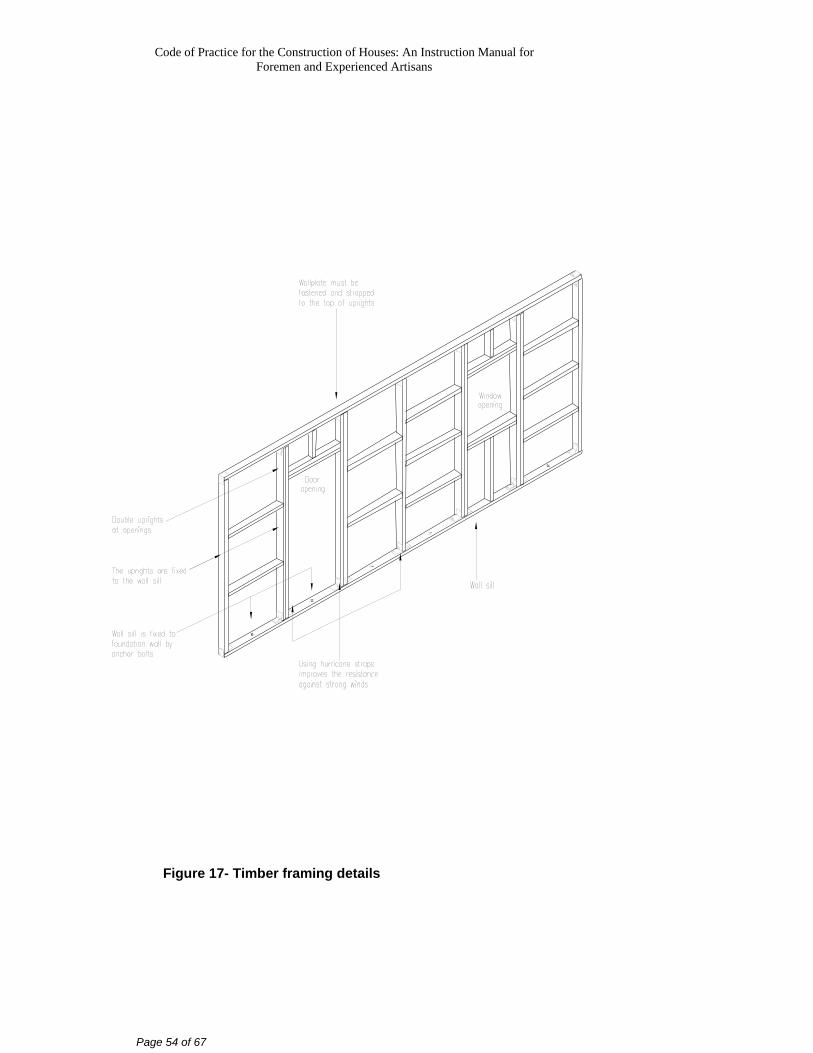
Figure 17- Timber framing details
Code of Practice for the Construction of Houses: An Instruction Manual for Foremen and Experienced Artisans
Page 55 of 67
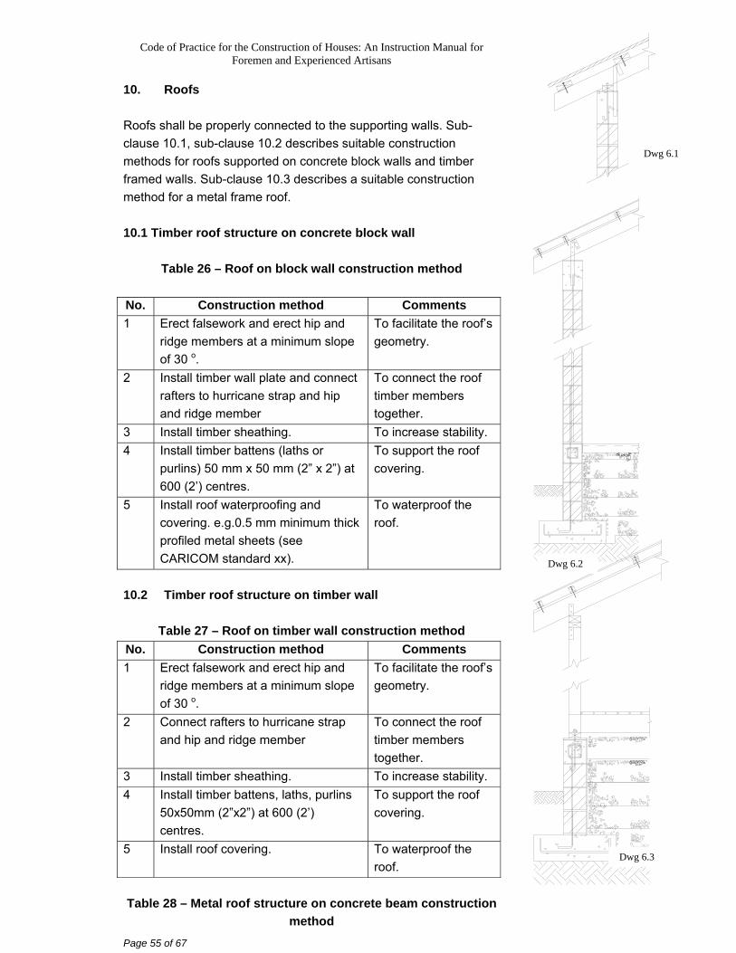
10. Roofs Roofs shall be properly connected to the supporting walls. Sub-clause 10.1, sub-clause 10.2 describes suitable construction methods for roofs supported on concrete block walls and timber framed walls. Sub-clause 10.3 describes a suitable construction method for a metal frame roof. 10.1 Timber roof structure on concrete block wall
Table 26 – Roof on block wall construction method
No. Construction method Comments 1 Erect falsework and erect hip and
ridge members at a minimum slope of 30 o.
To facilitate the roof’s geometry.
2 Install timber wall plate and connect rafters to hurricane strap and hip and ridge member
To connect the roof timber members together.
3 Install timber sheathing. To increase stability. 4 Install timber battens (laths or
purlins) 50 mm x 50 mm (2” x 2”) at 600 (2’) centres.
To support the roof covering.
5 Install roof waterproofing and covering. e.g.0.5 mm minimum thick profiled metal sheets (see CARICOM standard xx).
To waterproof the roof.
10.2 Timber roof structure on timber wall
Table 27 – Roof on timber wall construction method No. Construction method Comments 1 Erect falsework and erect hip and
ridge members at a minimum slope of 30 o.
To facilitate the roof’s geometry.
2 Connect rafters to hurricane strap and hip and ridge member
To connect the roof timber members together.
3 Install timber sheathing. To increase stability. 4 Install timber battens, laths, purlins
50x50mm (2”x2”) at 600 (2’) centres.
To support the roof covering.
5 Install roof covering. To waterproof the roof.
Table 28 – Metal roof structure on concrete beam construction
method
Dwg 6.1
Dwg 6.2
Dwg 6.3
Code of Practice for the Construction of Houses: An Instruction Manual for Foremen and Experienced Artisans
Page 56 of 67
No. Construction method Comments 1 Bolt metal rafters to RC ring beam
at a minimum slope of 30 o in a hip shape.
To facilitate the roof’s geometry.
2 Connect metal purlins to rafters. To support the roof covering.
3 Connect 0.5 mm thick metal roof profiled sheeting to purlins.
To prevent the roof covering from blowing away.
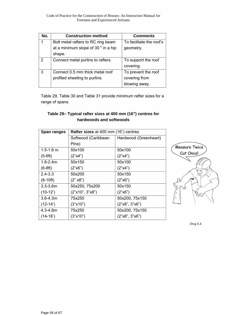
Table 29, Table 30 and Table 31 provide minimum rafter sizes for a range of spans.
Table 29– Typical rafter sizes at 400 mm (16”) centres for hardwoods and softwoods
Rafter sizes at 400 mm (16”) centres Span ranges Softwood (Caribbean Pine)
Hardwood (Greenheart)
1.5-1.8 m (5-6ft)
50x100 (2”x4”)
50x100 (2”x4”)
1.8-2.4m (6-8ft)
50x150 (2”x6”)
50x100 (2”x4”)
2.4-3.3 (8-10ft)
50x200 (2” x8”)
50x150 (2”x6”)
3.3-3.6m (10-12’)
50x250, 75x200 (2”x10”, 3”x8”)
50x150 (2”x6”)
3.6-4.3m (12-14’)
75x250 (3”x10”)
50x200, 75x150 (2”x8”, 3”x6”)
4.3-4.8m (14-16’)
75x250 (3”x10”)
50x200, 75x150 (2”x8”, 3”x6”)
Dwg 6.4
Code of Practice for the Construction of Houses: An Instruction Manual for Foremen and Experienced Artisans
Page 57 of 67
Table 30 – Typical rafter sizes at 600 mm (24”) centres for hardwoods and softwoods
Rafter sizes at 600 mm (24”) centres Span ranges Softwood (Caribbean Pine)
Hardwood (Greenheart)
1.5-1.8 m (5-6ft)
50x150 (2”x6”)
50x100 (2”x4”)
1.8-2.4m (6-8ft)
50x200, 75x150 (2”x8”, 3”x6”)
50x150 (2”x6”)
2.4-3.3 (8-10ft)
50x250, 75x200 (2”x10”, 3”x8”)
50x150 (2”x6”)
3.3-3.6m (10-12’)
75x250 (3”x10”)
50x200, 75x150 (2”x8”, 3”x6”)
3.6-4.3m (12-14’)
75x250 (3”x10”)
50x200, 75x150 (2”x8”, 3”x6”)
4.3-4.8m (14-16’)
75x300 mm (3”x12”)
50x250, 75x200 (2”x10”, 3”x8”)
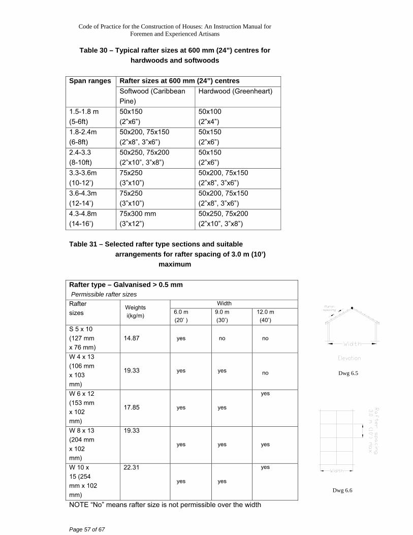
Table 31 – Selected rafter type sections and suitable
arrangements for rafter spacing of 3.0 m (10’) maximum
Rafter type – Galvanised > 0.5 mm Permissible rafter sizes
Width Rafter sizes
Weights i(kg/m) 6.0 m
(20’ ) 9.0 m (30’)
12.0 m (40’)
S 5 x 10 (127 mm x 76 mm)
14.87 yes no no
W 4 x 13 (106 mm x 103 mm)
19.33 yes yes
no
W 6 x 12 (153 mm x 102 mm)
17.85 yes yes
yes
W 8 x 13 (204 mm x 102 mm)
19.33
yes yes yes
W 10 x 15 (254 mm x 102 mm)
22.31
yes yes
yes
NOTE “No” means rafter size is not permissible over the width
Dwg 6.5
Dwg 6.6
Code of Practice for the Construction of Houses: An Instruction Manual for Foremen and Experienced Artisans
Page 58 of 67
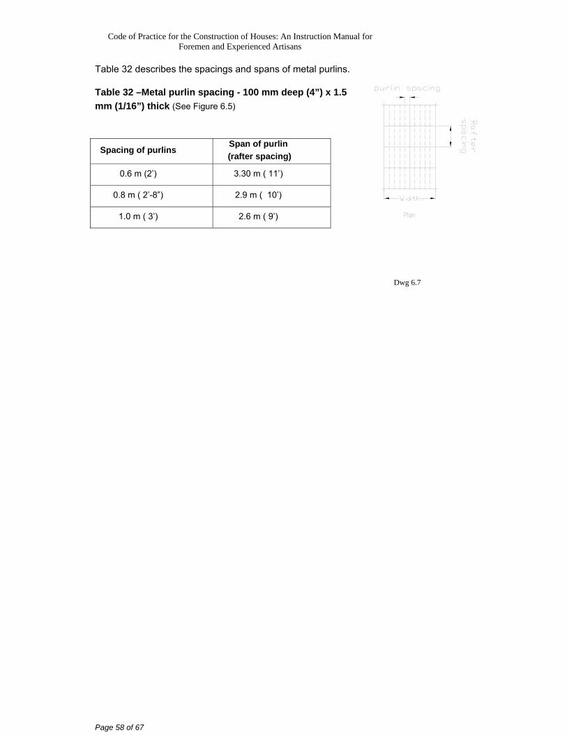
Table 32 describes the spacings and spans of metal purlins. Table 32 –Metal purlin spacing - 100 mm deep (4”) x 1.5 mm (1/16”) thick (See Figure 6.5)
Spacing of purlins Span of purlin
(rafter spacing)
0.6 m (2’) 3.30 m ( 11’)
0.8 m ( 2’-8”) 2.9 m ( 10’)
1.0 m ( 3’) 2.6 m ( 9’)
Dwg 6.7
Code of Practice for the Construction of Houses: An Instruction Manual for Foremen and Experienced Artisans
Page 59 of 67
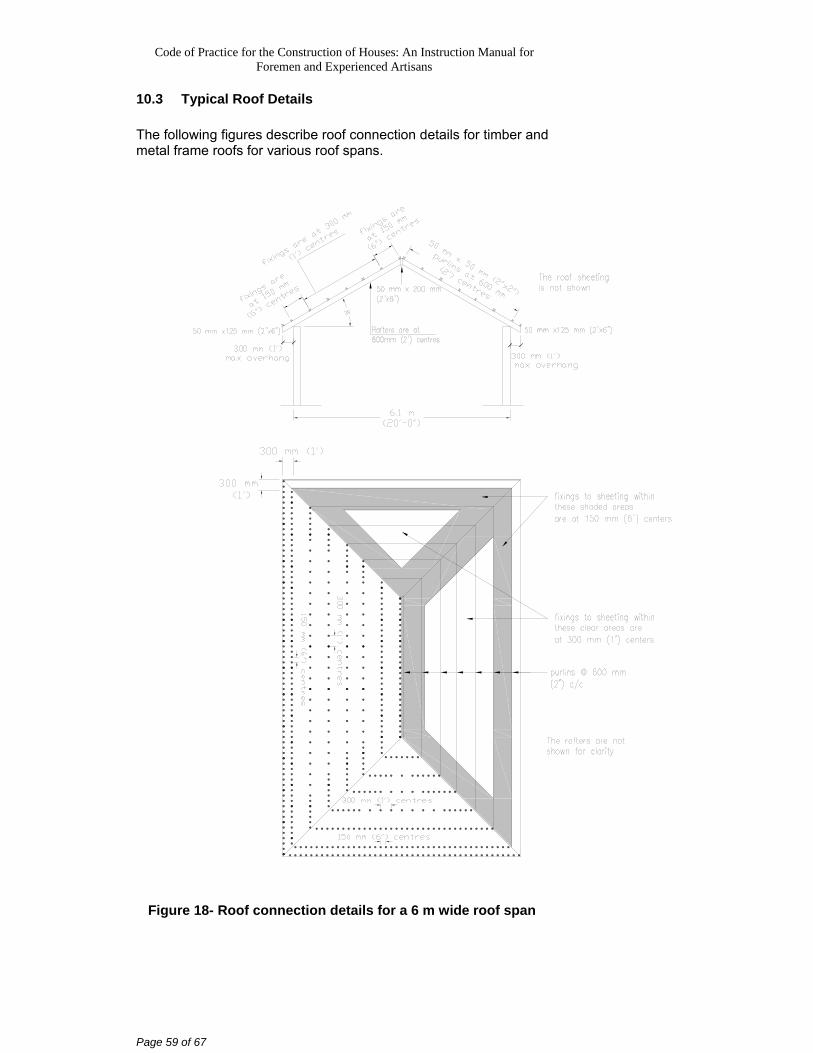
10.3 Typical Roof Details The following figures describe roof connection details for timber and metal frame roofs for various roof spans.
Figure 18- Roof connection details for a 6 m wide roof span
Code of Practice for the Construction of Houses: An Instruction Manual for Foremen and Experienced Artisans
Page 60 of 67
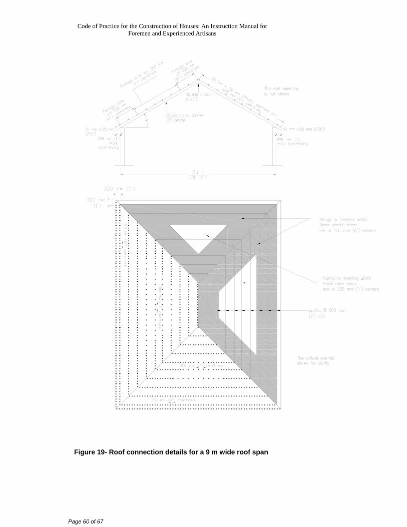
Figure 19- Roof connection details for a 9 m wide roof span
Code of Practice for the Construction of Houses: An Instruction Manual for Foremen and Experienced Artisans
Page 61 of 67
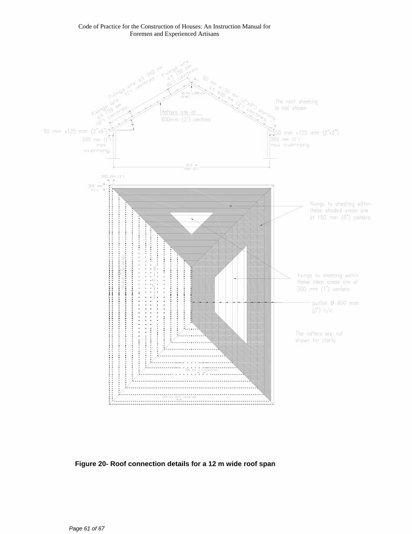
Figure 20- Roof connection details for a 12 m wide roof span
Code of Practice for the Construction of Houses: An Instruction Manual for Foremen and Experienced Artisans
Page 62 of 67
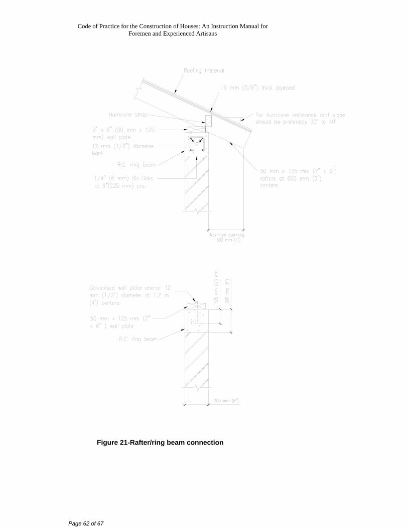
Figure 21-Rafter/ring beam connection
Code of Practice for the Construction of Houses: An Instruction Manual for Foremen and Experienced Artisans
Page 63 of 67
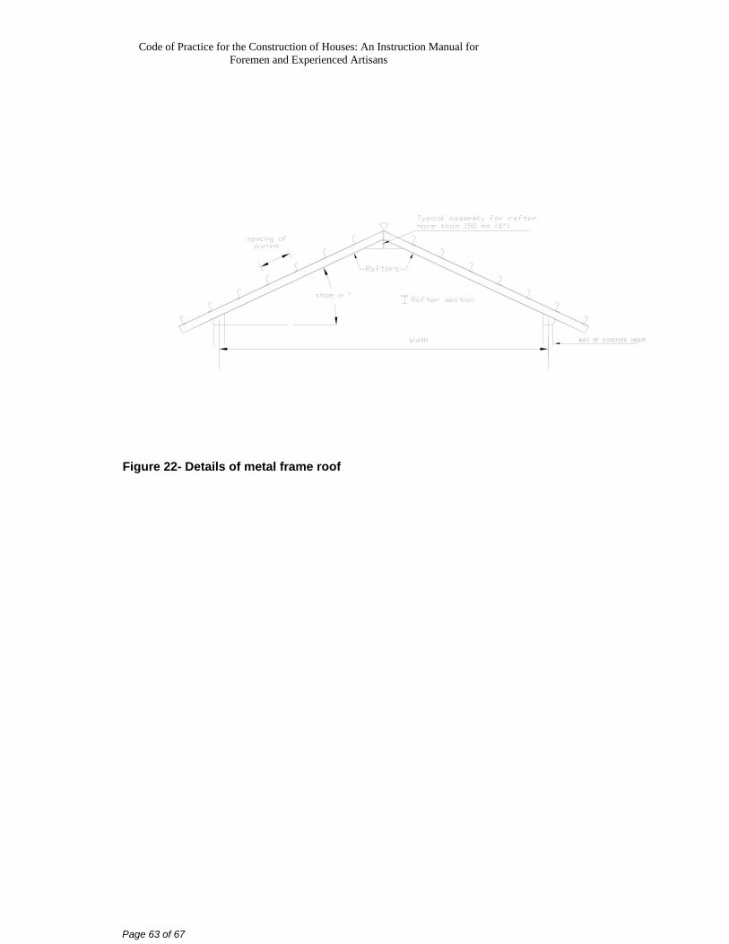
Figure 22- Details of metal frame roof
Code of Practice for the Construction of Houses: An Instruction Manual for Foremen and Experienced Artisans
Page 64 of 67
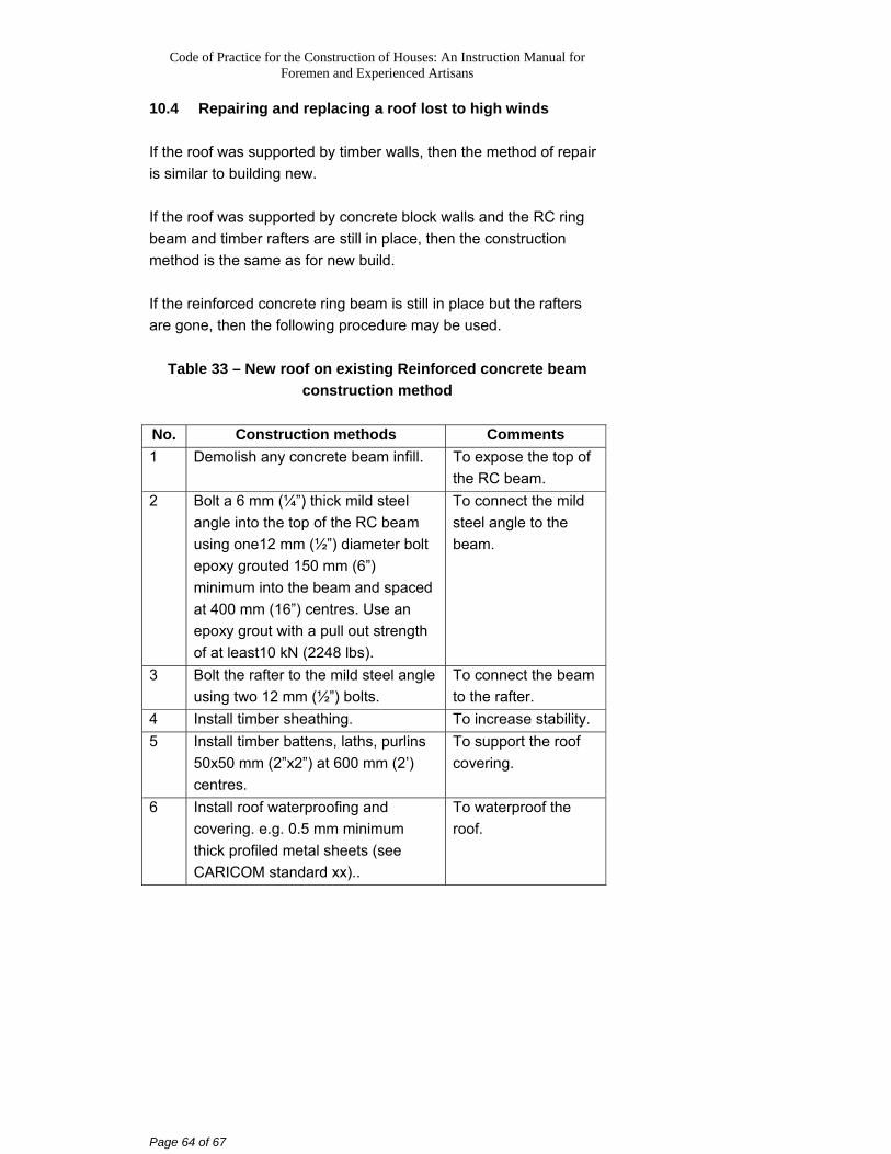
10.4 Repairing and replacing a roof lost to high winds If the roof was supported by timber walls, then the method of repair is similar to building new. If the roof was supported by concrete block walls and the RC ring beam and timber rafters are still in place, then the construction method is the same as for new build. If the reinforced concrete ring beam is still in place but the rafters are gone, then the following procedure may be used.
Table 33 – New roof on existing Reinforced concrete beam
construction method
No. Construction methods Comments 1 Demolish any concrete beam infill. To expose the top of
the RC beam. 2 Bolt a 6 mm (¼”) thick mild steel
angle into the top of the RC beam using one12 mm (½”) diameter bolt epoxy grouted 150 mm (6”) minimum into the beam and spaced at 400 mm (16”) centres. Use an epoxy grout with a pull out strength of at least10 kN (2248 lbs).
To connect the mild steel angle to the beam.
3 Bolt the rafter to the mild steel angle using two 12 mm (½”) bolts.
To connect the beam to the rafter.
4 Install timber sheathing. To increase stability. 5 Install timber battens, laths, purlins
50x50 mm (2”x2”) at 600 mm (2’) centres.
To support the roof covering.
6 Install roof waterproofing and covering. e.g. 0.5 mm minimum thick profiled metal sheets (see CARICOM standard xx)..
To waterproof the roof.
Code of Practice for the Construction of Houses: An Instruction Manual for Foremen and Experienced Artisans
Page 65 of 67
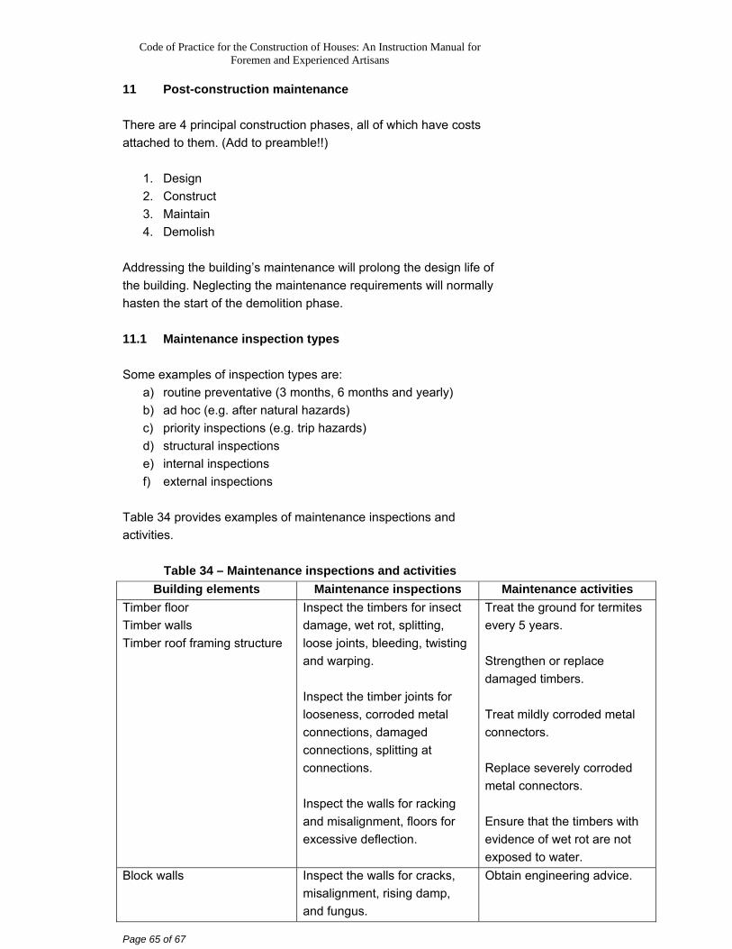
11 Post-construction maintenance There are 4 principal construction phases, all of which have costs attached to them. (Add to preamble!!)
1. Design 2. Construct 3. Maintain 4. Demolish
Addressing the building’s maintenance will prolong the design life of the building. Neglecting the maintenance requirements will normally hasten the start of the demolition phase. 11.1 Maintenance inspection types Some examples of inspection types are:
a) routine preventative (3 months, 6 months and yearly) b) ad hoc (e.g. after natural hazards) c) priority inspections (e.g. trip hazards) d) structural inspections e) internal inspections f) external inspections
Table 34 provides examples of maintenance inspections and activities.
Table 34 – Maintenance inspections and activities Building elements Maintenance inspections Maintenance activities
Timber floor Timber walls Timber roof framing structure
Inspect the timbers for insect damage, wet rot, splitting, loose joints, bleeding, twisting and warping. Inspect the timber joints for looseness, corroded metal connections, damaged connections, splitting at connections. Inspect the walls for racking and misalignment, floors for excessive deflection.
Treat the ground for termites every 5 years. Strengthen or replace damaged timbers. Treat mildly corroded metal connectors. Replace severely corroded metal connectors. Ensure that the timbers with evidence of wet rot are not exposed to water.
Block walls Inspect the walls for cracks, misalignment, rising damp, and fungus.
Obtain engineering advice.
Code of Practice for the Construction of Houses: An Instruction Manual for Foremen and Experienced Artisans
Page 66 of 67
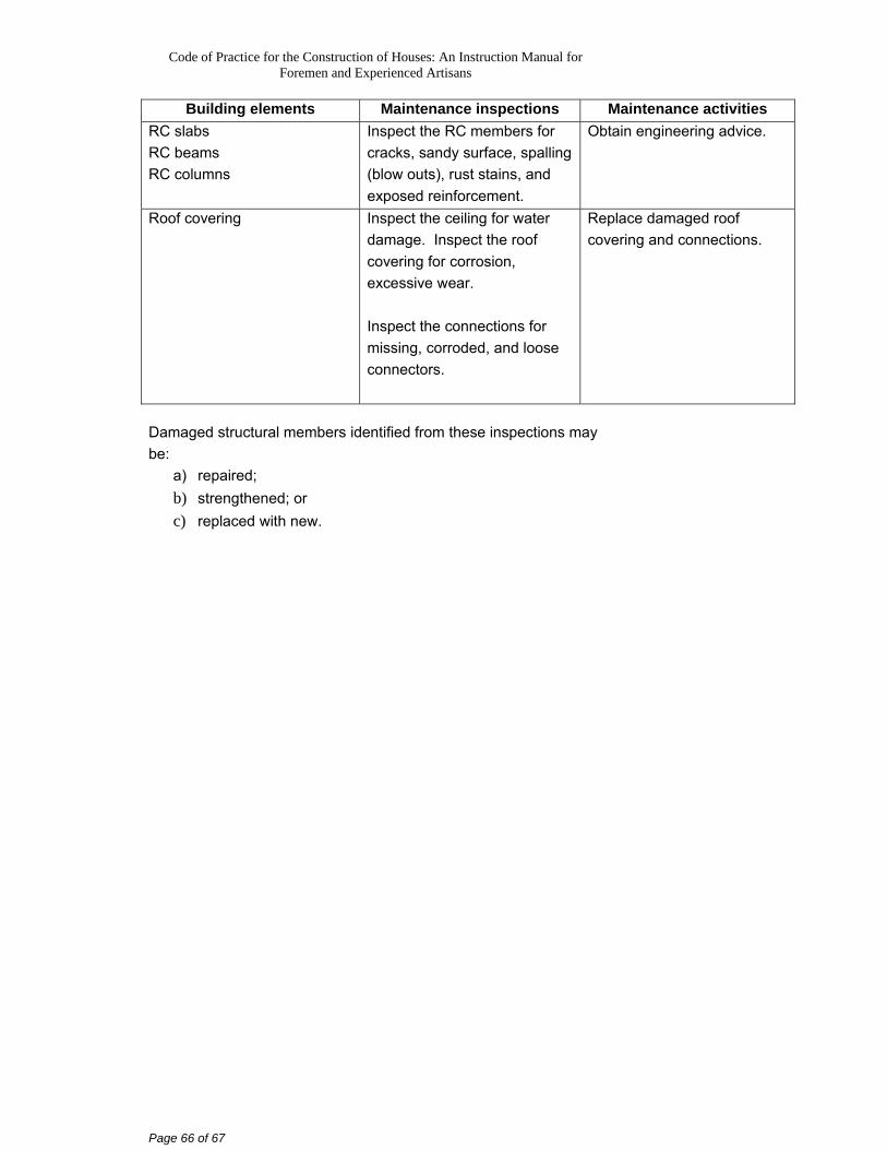
Building elements Maintenance inspections Maintenance activities RC slabs RC beams RC columns
Inspect the RC members for cracks, sandy surface, spalling (blow outs), rust stains, and exposed reinforcement.
Obtain engineering advice.
Roof covering Inspect the ceiling for water damage. Inspect the roof covering for corrosion, excessive wear. Inspect the connections for missing, corroded, and loose connectors.
Replace damaged roof covering and connections.
Damaged structural members identified from these inspections may be:
a) repaired; b) strengthened; or c) replaced with new.
Code of Practice for the Construction of Houses: An Instruction Manual for Foremen and Experienced Artisans
Page 67 of 67
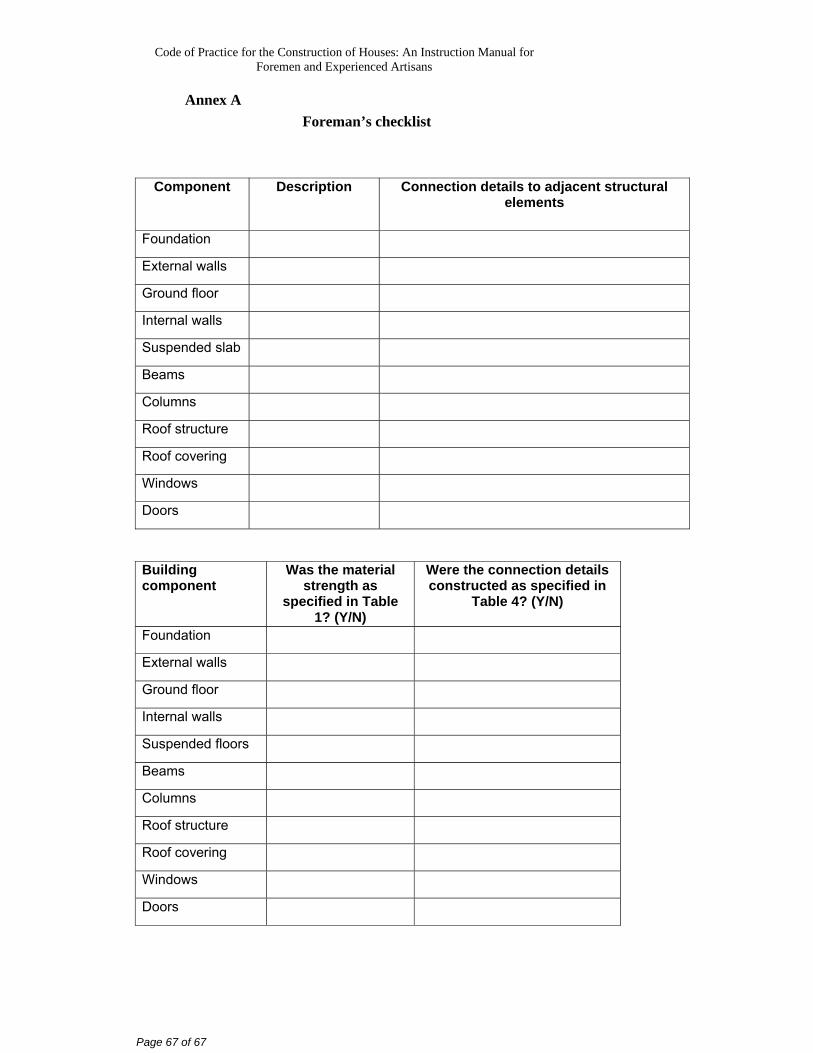
Annex A Foreman’s checklist
Component Description Connection details to adjacent structural
elements
Foundation
External walls
Ground floor
Internal walls
Suspended slab
Beams
Columns
Roof structure
Roof covering
Windows
Doors
Building component
Was the material strength as
specified in Table 1? (Y/N)
Were the connection details constructed as specified in
Table 4? (Y/N)
Foundation
External walls
Ground floor
Internal walls
Suspended floors
Beams
Columns
Roof structure
Roof covering
Windows
Doors