Overview of program analysis Mooly Sagiv html://msagiv/courses/wcc05.html.
date post
21-Dec-2015Category
view
219download
0
Code Generation
Mooly Sagiv
html://www.cs.tau.ac.il/~msagiv/courses/wcc04.html
Chapter 4

Basic Compiler Phases

Code generation issues
• Code selection
• Register allocation
• Instruction ordering

Simplifications
• Consider small parts of AST at time– One expression at the time
• Target machine simplifications– Ignore certain instructions
• Use simplifying conventions

Overall Structure

Outline
• Partial evaluation in the nutshell• Simple code generation for expressions (4.2.4,
4.3)– Pure stack machine– Pure register machine
• Code generation of basic blocks (4.2.5)• [Automatic generation of code generators (4.2.6)]• Next lesson
– Program Analysis – Activation frames

Partial Evaluation
• Partially interpret static parts in a program
• Generates an equivalent program
Partial EvaluatorProgram Program’
Input 1Input 2
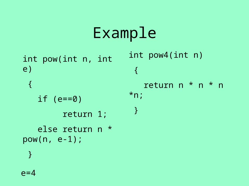
Example
int pow(int n, int e)
{
if (e==0)
return 1;
else return n * pow(n, e-1);
}
e=4
int pow4(int n)
{
return n * n * n *n;
}
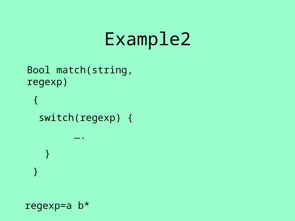
Example2
Bool match(string, regexp)
{
switch(regexp) {
….
}
}
regexp=a b*

Partial Evaluation Generalizes Compilation
Partial EvaluatorInterpreter Program
AST ProgramInput

But ….
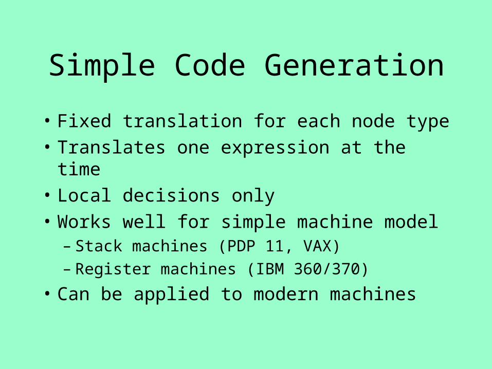
Simple Code Generation
• Fixed translation for each node type
• Translates one expression at the time
• Local decisions only
• Works well for simple machine model– Stack machines (PDP 11, VAX)– Register machines (IBM 360/370)
• Can be applied to modern machines
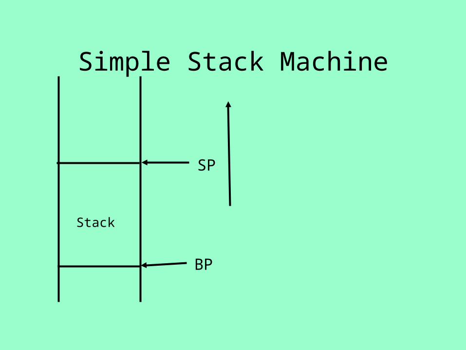
Simple Stack Machine
BP
SP
Stack

Stack Machine Instructions

Example
p := p + 5Push_Local #p
Push_Const 5
Add_Top2
Store_Local #p

Simple Stack Machine
BP
SP
Push_Local #p
Push_Const 5
Add_Top2
Store_Local #p7 BP+5

Simple Stack Machine
BP
SPPush_Local #p
Push_Const 5
Add_Top2
Store_Local #p
7
BP+57

Simple Stack Machine
BP
SPPush_Local #p
Push_Const 5
Add_Top2
Store_Local #p
7
BP+57
5
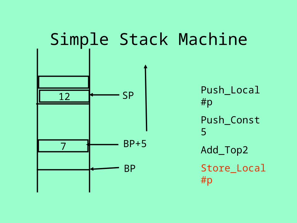
Simple Stack Machine
BP
SP Push_Local #p
Push_Const 5
Add_Top2
Store_Local #p
12
BP+57

Simple Stack Machine
BP
SP
Push_Local #p
Push_Const 5
Add_Top2
Store_Local #pBP+512

Register Machine
• Fixed set of registers
• Load and store from/to memory
• Arithmetic operations on register only

Register Machine Instructions

Example
p := p + 5Load_Mem p, R1
Load_Const 5, R2
Add_Reg R2, R1
Store_Reg R1, P

Simple Register Machine
Load_Mem p, R1
Load_Const 5, R2
Add_Reg R2, R1
Store_Reg R1, P7 x770
memory
R1 R2

Simple Register Machine
Load_Mem p, R1
Load_Const 5, R2
Add_Reg R2, R1
Store_Reg R1, P7 x770
memory
7
R1 R2

Simple Register Machine
Load_Mem p, R1
Load_Const 5, R2
Add_Reg R2, R1
Store_Reg R1, P7 x770
memory
57
R1 R2

Simple Register Machine
Load_Mem p, R1
Load_Const 5, R2
Add_Reg R2, R1
Store_Reg R1, P7 x770
memory
512
R1 R2

Simple Register Machine
Load_Mem p, R1
Load_Const 5, R2
Add_Reg R2, R1
Store_Reg R1, P12 x770
memory
512
R1 R2

Simple Code Generation for Stack Machine
• Tree rewritings
• Bottom up AST traversal

Abstract Syntax Trees for Stack Machine Instructions

Example
-
*
*
b b 4 *
a c
Push_Local #b Push_Local #b
Mult_Top2
Push_Constant 4
Push_Local #a Push_Local #c
Mult_Top2
Mult_Top2
Subt_Top2

Bottom-Up Code Generation

Simple Code Generation forRegister Machine
• Need to allocate register for temporary values– AST nodes
• The number of machine registers may not suffice
• Simple Algorithm: – Bottom up code generation– Allocate registers for subtrees

Register Machine Instructions

Abstract Syntax Trees forRegister Machine Instructions

Simple Code Generation
• Assume enough registers
• Use DFS to:– Generate code – Assign Registers
• Target register
• Auxiliary registers
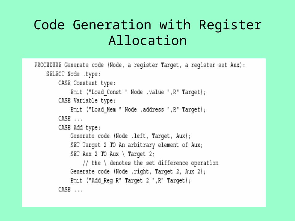
Code Generation with Register Allocation

Code Generation with Register Allocation(2)

Example
-
*
*
b b 4 *
a c
Load_Mem b, R1 Load_Mem b, R2
Mult_Reg R2, R1
Load_Constant 4, R2
Load_Mem a, R3 Load_Mem c, R4
Mult_Reg R4, R3
Mult_Reg R3, R2
Subt_Reg R1, R2
T=R1
T=R1
T=R1
T=R2
T=R2
T=R2
T=R3
T=R3 T=R4

Example

Runtime Evaluation

Optimality
• The generated code is suboptimal
• May consume more registers than necessary– May require storing temporary results
• Leads to larger execution time

Example

Observation (Aho&Sethi)
• The compiler can reorder the computations of sub-expressions
• The code of the right-subtree can appear before the code of the left-subtree
• May lead to faster code

Example
-
*
*
b b 4 *
a c
Load_Mem b, R1 Load_Mem b, R2
Mult_Reg R2, R1
Load_Constant 4, R3
Load_Mem a, R2 Load_Mem c, R3
Mult_Reg R3, R2
Mult_Reg R2, R3
Subt_Reg R3, R1
T=R1
T=R1
T=R1
T=R2
T=R2
T=R3
T=R2
T=R2 T=R3

Example
Load_Mem b, R1
Load_Mem b, R2
Mult_Reg R2, R1
Load_Mem a, R2
Load_Mem c, R3
Mult_Reg R3, R2
Load_Constant 4, R3
Mult_Reg R2, R3
Subt_Reg R3, R1

Two Phase SolutionDynamic Programming
Sethi & Ullman
• Bottom-up (labeling)– Compute for every subtree
• The minimal number of registers needed• Weight
• Top-Down– Generate the code using labeling by preferring
“heavier” subtrees (larger labeling)

The Labeling Principle
+
m registers n registers
m > nm registers

The Labeling Principle
+
m registers n registers
m < nn registers

The Labeling Principle
+
m registers n registers
m = nm+1 registers

The Labeling Procedure

Labeling the example (weight)
-
*
*
b b 4 *
a c
1
2
1 1
1 1
2
2
3

Top-Down
-3
*2 *2
b1 b1 41 *2
a1 c1
Load_Mem b, R1 Load_Mem b, R2
Mult_Reg R2, R1
Load_Constant 4, R2
Load_Mem a, R3 Load_Mem c, R2
Mult_Reg R2, R3
Mult_Reg R3, R2
Subt_Reg R2, R1
T=R1
T=R1
T=R1
T=R2
T=R2
T=R2
T=R3
T=R3 T=R2

Generalizations
• More than two arguments for operators– Function calls
• Register/memory operations
• Multiple effected registers
• Spilling – Need more registers than available

Register Memory Operations
• Add_Mem X, R1
• Mult_Mem X, R1
• No need for registers to store right operands

Labeling the example (weight)
-
*
*
b b 4 *
a c
1
1
0 1
1 0
1
2
2

Top-Down
-2
*1 *2
b1 b0 41 *1
a1 c0
Load_Mem b, R1
Mult_Mem b, R1
Load_Constant 4, R2
Load_Mem a, R1
Mult_Mem c,R1
Mult_Reg R1, R2
Subt_Reg R2, R1
T=R1
T=R1
T=R1 T=R2
T=R2
T=R2
T=R1

Empirical Results
• Experience shows that for handwritten programs 5 registers suffice (Yuval 1977)
• But program generators may produce arbitrary complex expressions

Spilling
• Even an optimal register allocator can require more registers than available
• Need to generate code for every correct program
• The compiler can save temporary results– Spill registers into temporaries– Load when needed
• Many heuristics exist

Simple Spilling Method
• A `heavy’ tree contains a `heavy’ subtree whose dependents are ‘light’
• Heavy tree – Needs more registers than available
• Generate code for the light tree• Spill the content into memory and replace
subtree by temporary• Generate code for the resultant tree

Simple Spilling Method

Mult_Reg R2, R1
Top-Down (2 registers)
-3
*2 *2
b1 b1 41 *2
a1 c1
Load_Constant 4, R2
Load_Mem a, R2 Load_Mem c, R1
Mult_Reg R1, R2
Mult_Reg R2, R1
T=R1
T=R1
T=R2
T=R2 T=R1
Store_Reg R1, T1
T=R1
T=R1
T=R1
Load_Mem b, R1
T=R2
Load_Mem b, R2
Load_Mem T1, R2
Subt_Reg R2, R1

Top-Down (2 registers)
Load_Mem a, R2Load_Mem c, R1Mult_Reg R1, R2Load_Constant 4, R2Mult_Reg R2, R1Store_Reg R1, T1Load_Mem b, R1Load_Mem b, R2Mult_Reg R2, R1Load_Mem T1, R2Subtr_Reg R2, R1

Summary
• Register allocation of expressions is simple• Good in practice• Optimal under certain conditions
– Uniform instruction cost– `Symbolic’ trees
• Can handle non-uniform cost– Code-Generator Generators exist (BURS)
• Even simpler for 3-address machines• Simple ways to determine best orders• But misses opportunities to share registers between
different expressions– Can employ certain conventions
• Better solutions exist– Graph coloring

Code Generationfor Basic Blocks
Introduction
Chapter 4.2.5

The Code Generation Problem
• Given– AST– Machine description
• Number of registers
• Instructions + cost
• Generate code for AST with minimum cost
• NPC [Aho 77]

Example Machine Description

Simplifications
• Consider small parts of AST at time– One expression at the time
• Target machine simplifications– Ignore certain instructions
• Use simplifying conventions

Basic Block
• Parts of control graph without split
• A sequence of assignments and expressions which are always executed together
• Maximal Basic Block Cannot be extended– Start at label or at routine entry– Ends just before jump like node, label,
procedure call, routine exit

Examplevoid foo()
{
if (x > 8) {
z = 9;
t = z + 1;
}
z = z * z;
t = t – z ;
bar();
t = t + 1;
x>8
z=9;
t = z + 1;
z=z*z;
t = t - z;
bar()
t=t+1;

Running Example

Running Example AST

Optimized code(gcc)

Outline
• Dependency graphs for basic blocks
• Transformations on dependency graphs
• From dependency graphs into code– Instruction selection
(linearizations of dependency graphs)– Register allocation (the general idea)

Dependency graphs
• Threaded AST imposes an order of execution• The compiler can reorder assignments as long as
the program results are not changed• Define a partial order on assignments
– a < b a must be executed before b
• Represented as a directed graph– Nodes are assignments– Edges represent dependency
• Acyclic for basic blocks

Running Example

Sources of dependency
• Data flow inside expressions– Operator depends on operands– Assignment depends on assigned expressions
• Data flow between statements– From assignments to their use
• Pointers complicate dependencies

Sources of dependency
• Order of subexpresion evaluation is immaterial– As long as inside dependencies are respected
• The order of uses of a variable are immaterial as long as:– Come between
• Depending assignment
• Next assignment

Creating Dependency Graph from AST
1. Nodes AST becomes nodes of the graph
2. Replaces arcs of AST by dependency arrows• Operator Operand
3. Create arcs from assignments to uses
4. Create arcs between assignments of the same variable
5. Select output variables (roots)
6. Remove ; nodes and their arrows

Running Example

Dependency Graph Simplifications
• Short-circuit assignments– Connect variables to assigned expressions– Connect expression to uses
• Eliminate nodes not reachable from roots

Running Example

Cleaned-Up Data Dependency Graph

From Dependency Graph into Code
• Linearize the dependency graph– Instructions must follow dependency
• Many solutions exist• Select the one with small runtime cost• Assume infinite number of registers
– Symbolic registers
• Assign registers later – May need additional spill
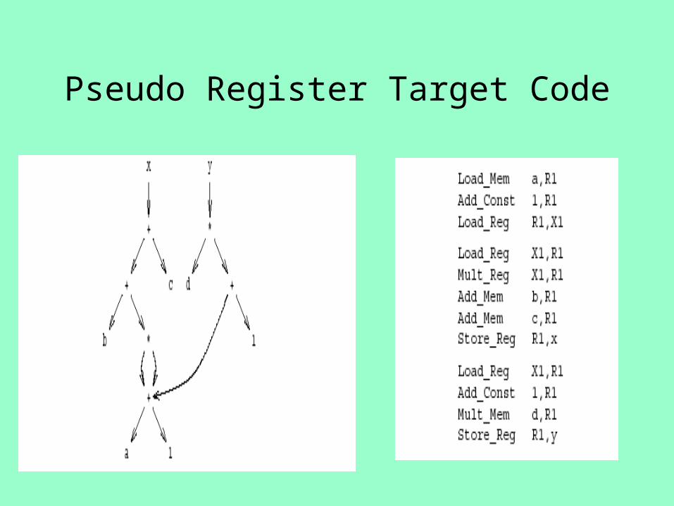
Pseudo Register Target Code

Register Allocation
• Maps symbolic registers into physical registers
• Reuse registers as much as possible• Graph coloring
– Undirected graph– Nodes = Registers (Symbolic and real)– Edges = Interference
• May require spilling
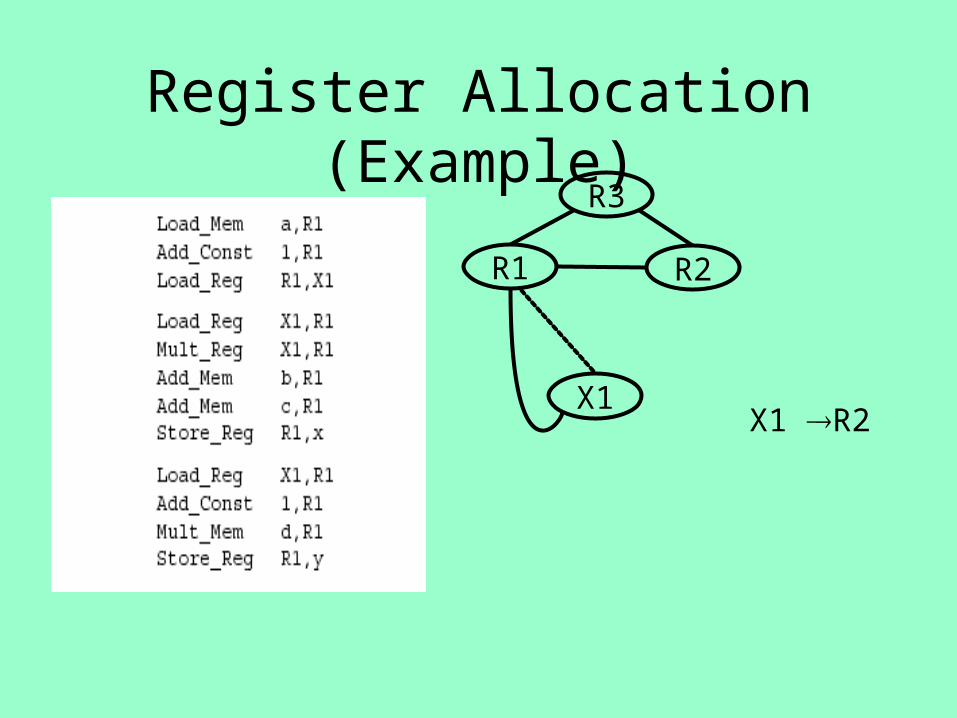
Register Allocation (Example)
R1 R2
X1
R3
X1 R2

Running Example

Summary
• Heuristics for code generation of basic blocks
• Works well in practice
• Fits modern machine architecture
• Can be extended to perform other tasks– Common subexpression elimination
• But basic blocks are small
• Can be generalized to a procedure


Tentative Schedule
20/12 Program Analysis
Activation Records
27/12 Register Allocation
3/1 Object Oriented
10/1 Assembler/Linker/Loader
17/1 Garbage Collection
14/2 Hazara