Code Compliant Construction - Structural building … · Code Compliant Construction of ......
57
Code Compliant Construction of Conventionally Framed Roofs and Roof Trusses Overview
Transcript of Code Compliant Construction - Structural building … · Code Compliant Construction of ......
Code Compliant Construction of Conventionally Framed Roofs and
Roof Trusses
Overview
Introduction
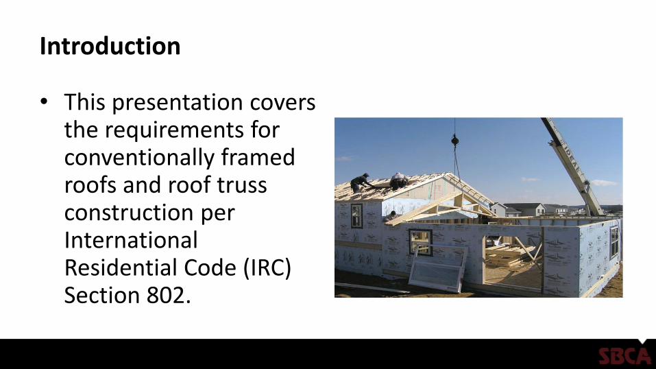
• This presentation covers the requirements for conventionally framed roofs and roof truss construction per International Residential Code (IRC) Section 802.
Background
• The code allows portions of a structure to be engineered in accordance with the International Building Code (IBC), without the entire structure requiring engineering. (R301.1.3)
• This means that some portions of the building may be engineered (e.g. trusses and other components), but the structure may still be able to utilize IRC prescriptive requirements.
Applications
• Structures within the scope of prescriptive code compliance include: – Detached one- and two-family dwellings and townhouses with
separate means of egress [R101.2]
– Light-frame construction (platform or balloon frame) [R301.1.2]
Prescriptive Code Compliance
• The following three tables list additional criteria the structure must meet with respect to loads and geometry:
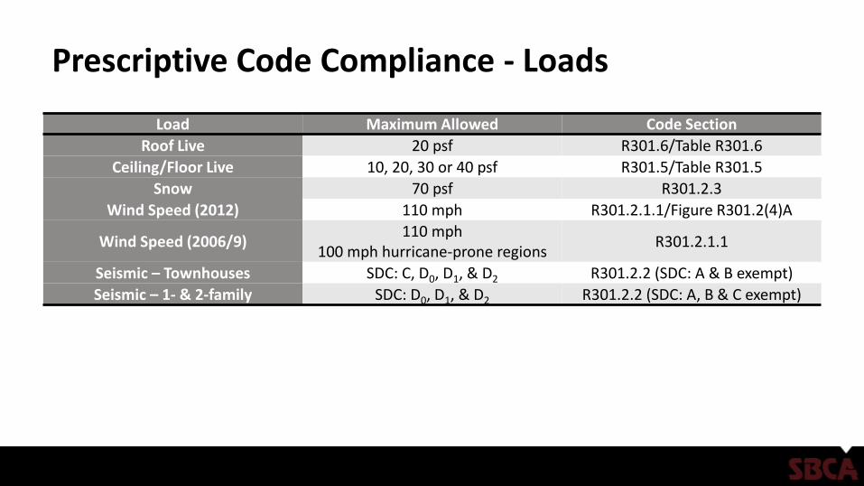
Prescriptive Code Compliance - Loads
Load Maximum Allowed Code Section
Roof Live 20 psf R301.6/Table R301.6
Ceiling/Floor Live 10, 20, 30 or 40 psf R301.5/Table R301.5
Snow 70 psf R301.2.3
Wind Speed (2012) 110 mph R301.2.1.1/Figure R301.2(4)A
Wind Speed (2006/9)110 mph
100 mph hurricane-prone regionsR301.2.1.1
Seismic – Townhouses SDC: C, D0, D1, & D2 R301.2.2 (SDC: A & B exempt)
Seismic – 1- & 2-family SDC: D0, D1, & D2 R301.2.2 (SDC: A, B & C exempt)
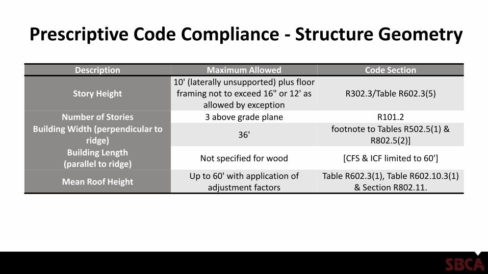
Prescriptive Code Compliance - Structure Geometry
Description Maximum Allowed Code Section
Story Height10' (laterally unsupported) plus floor framing not to exceed 16" or 12' as
allowed by exceptionR302.3/Table R602.3(5)
Number of Stories 3 above grade plane R101.2
Building Width (perpendicular to ridge)
36'footnote to Tables R502.5(1) &
R802.5(2)]
Building Length (parallel to ridge)
Not specified for wood [CFS & ICF limited to 60']
Mean Roof HeightUp to 60' with application of
adjustment factorsTable R602.3(1), Table R602.10.3(1)
& Section R802.11.
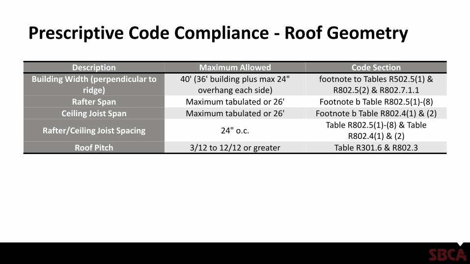
Prescriptive Code Compliance - Roof Geometry
Description Maximum Allowed Code Section
Building Width (perpendicular to ridge)
40' (36' building plus max 24" overhang each side)
footnote to Tables R502.5(1) & R802.5(2) & R802.7.1.1
Rafter Span Maximum tabulated or 26' Footnote b Table R802.5(1)-(8)
Ceiling Joist Span Maximum tabulated or 26' Footnote b Table R802.4(1) & (2)
Rafter/Ceiling Joist Spacing 24" o.c.Table R802.5(1)-(8) & Table
R802.4(1) & (2)
Roof Pitch 3/12 to 12/12 or greater Table R301.6 & R802.3
Prescriptive Code Compliance
• Finally, and perhaps most importantly, to meet prescriptive code compliance: – Construction documents shall be of sufficient clarity to indicate the
location, nature and extent of work and show in detail that such work conforms to the provisions of the code [R106.1.1].
– A complete load path from peak of roof to the foundation is required [R301.1].
What is a Load Path?
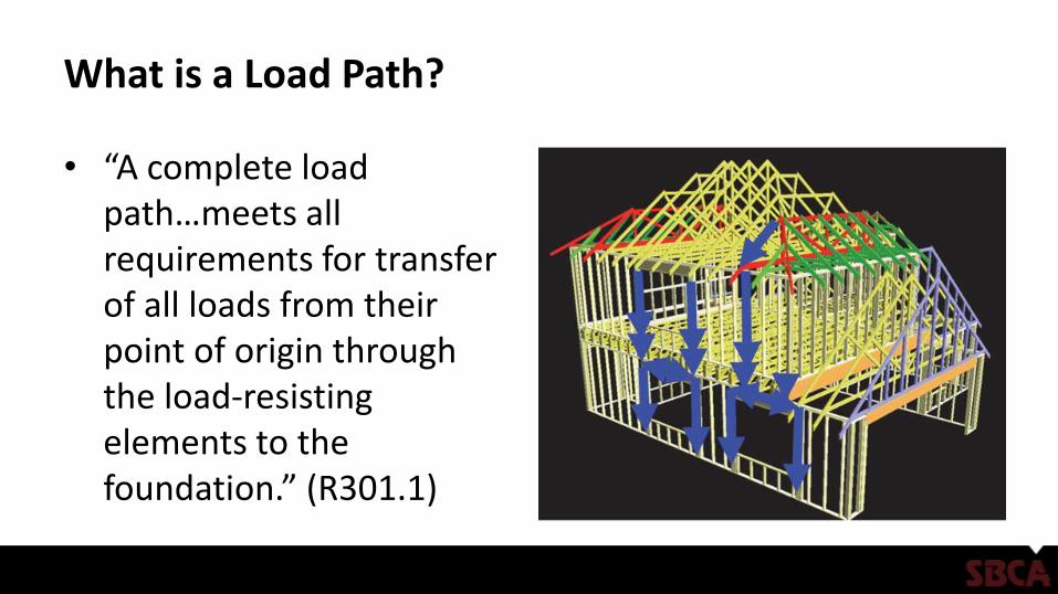
• “A complete load path…meets all requirements for transfer of all loads from their point of origin through the load-resisting elements to the foundation.” (R301.1)
What is a Load Path?
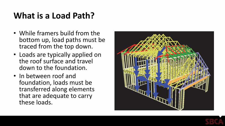
• While framers build from the bottom up, load paths must be traced from the top down.
• Loads are typically applied on the roof surface and travel down to the foundation.
• In between roof and foundation, loads must be transferred along elements that are adequate to carry these loads.
What is a Load Path?
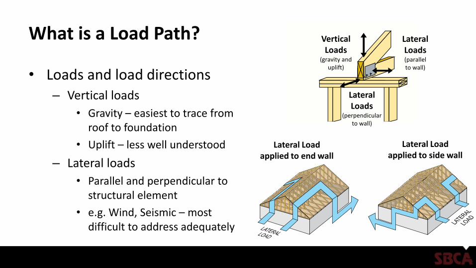
• Loads and load directions– Vertical loads
• Gravity – easiest to trace from roof to foundation
• Uplift – less well understood
– Lateral loads
• Parallel and perpendicular to structural element
• e.g. Wind, Seismic – most difficult to address adequately
VerticalLoads
(gravity anduplift)
LateralLoads
(perpendicularto wall)
LateralLoads(parallelto wall)
Lateral Loadapplied to end wall
Lateral Loadapplied to side wall
Conventional Framing Problem Areas
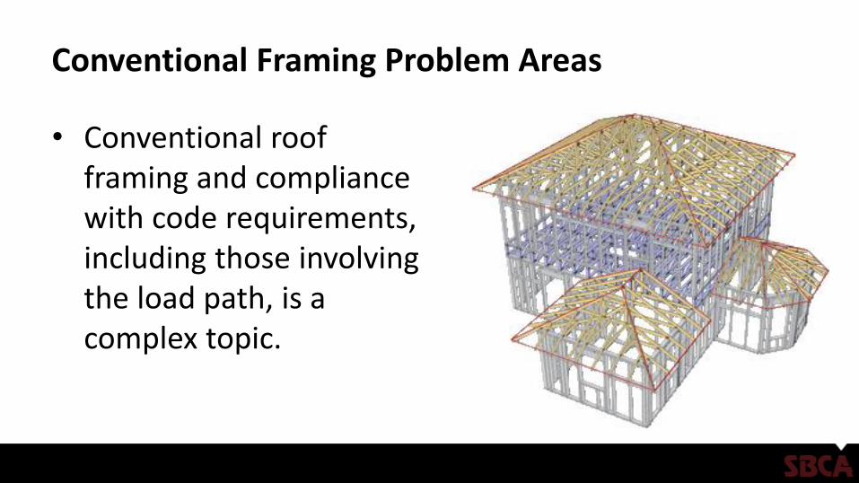
• Conventional roof framing and compliance with code requirements, including those involving the load path, is a complex topic.
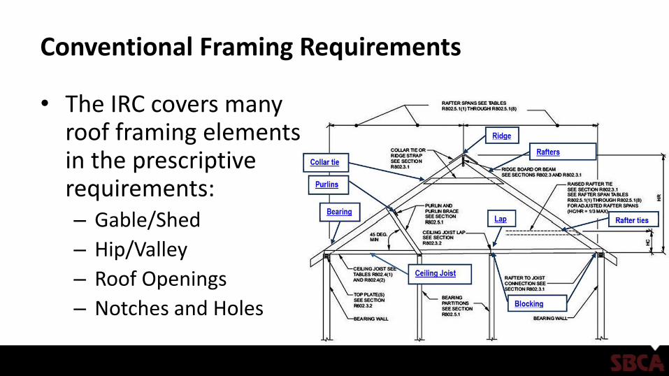
Conventional Framing Requirements
• The IRC covers many roof framing elements in the prescriptive requirements:– Gable/Shed
– Hip/Valley
– Roof Openings
– Notches and Holes
Conventional Framing Requirements
• However, the IRC gives no guidance on other aspects of the roof framing, such as:– Bracing design for high end of hip/valley rafters
– Bracing design for rafter purlins
– Non-symmetrical hip roofs
– Roof diaphragms with plate height changes
– Large roof openings (greater than 6' wide)
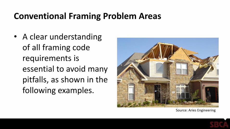
Conventional Framing Problem Areas
• A clear understanding of all framing code requirements is essential to avoid many pitfalls, as shown in the following examples.
Source: Aries Engineering
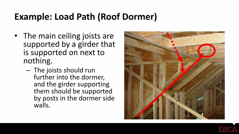
Example: Load Path (Roof Dormer)
• The main ceiling joists are supported by a girder that is supported on next to nothing. – The joists should run
further into the dormer, and the girder supporting them should be supported by posts in the dormer side walls.
Example: Load Path (Roof Dormer)
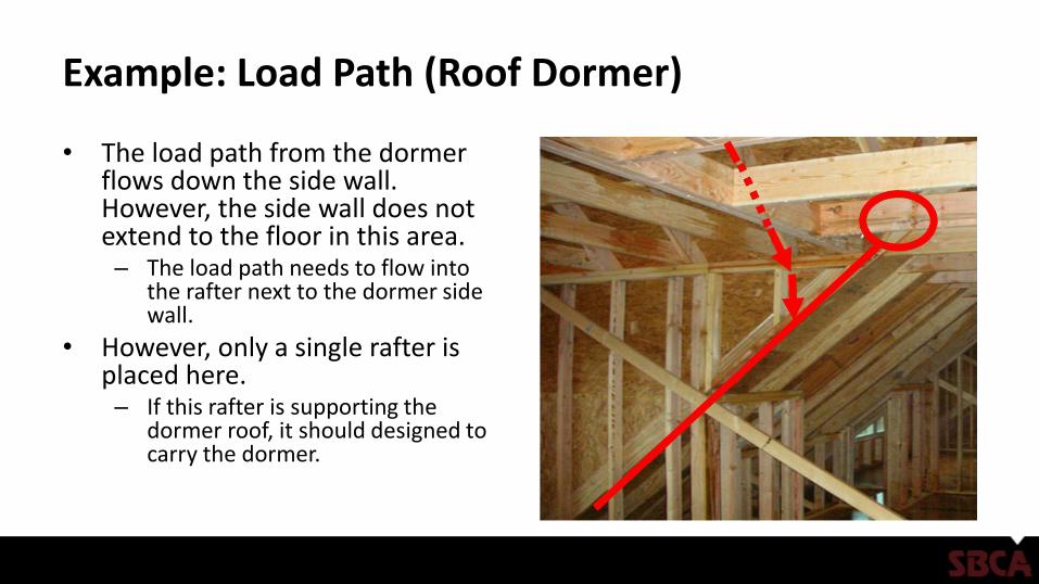
• The load path from the dormer flows down the side wall. However, the side wall does not extend to the floor in this area. – The load path needs to flow into
the rafter next to the dormer side wall.
• However, only a single rafter is placed here. – If this rafter is supporting the
dormer roof, it should designed to carry the dormer.
Example: Load Path (Roof Dormer)
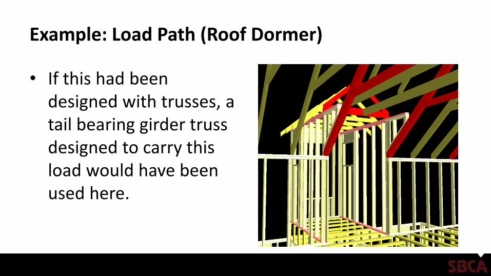
• If this had been designed with trusses, a tail bearing girder truss designed to carry this load would have been used here.
Example: Load Path (Wall)
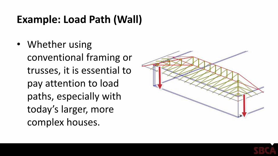
• Whether using conventional framing or trusses, it is essential to pay attention to load paths, especially with today’s larger, more complex houses.
Example: Load Path (Wall)
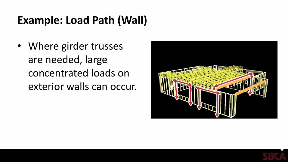
• Where girder trusses are needed, large concentrated loads on exterior walls can occur.
Example: Load Path (Wall)
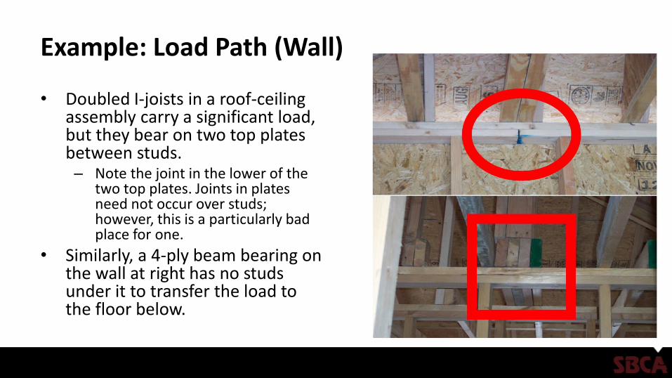
• Doubled I-joists in a roof-ceiling assembly carry a significant load, but they bear on two top plates between studs. – Note the joint in the lower of the
two top plates. Joints in plates need not occur over studs; however, this is a particularly bad place for one.
• Similarly, a 4-ply beam bearing on the wall at right has no studs under it to transfer the load to the floor below.
Example: Load Path (Wall)
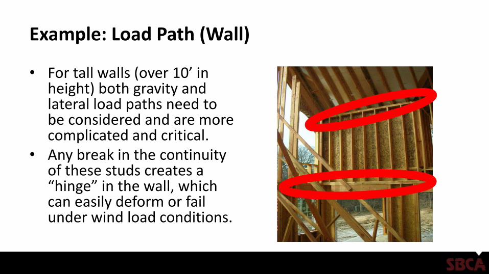
• For tall walls (over 10’ in height) both gravity and lateral load paths need to be considered and are more complicated and critical.
• Any break in the continuity of these studs creates a “hinge” in the wall, which can easily deform or fail under wind load conditions.
Example: Load Path (Wall)
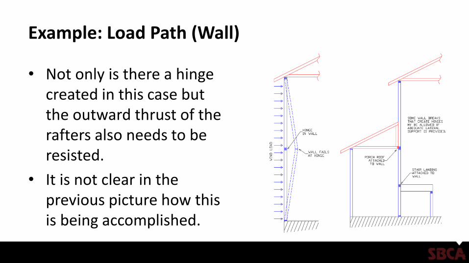
• Not only is there a hinge created in this case but the outward thrust of the rafters also needs to be resisted.
• It is not clear in the previous picture how this is being accomplished.
Example: Load Path (Floor)
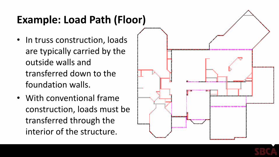
• In truss construction, loads are typically carried by the outside walls and transferred down to the foundation walls.
• With conventional frame construction, loads must be transferred through the interior of the structure.
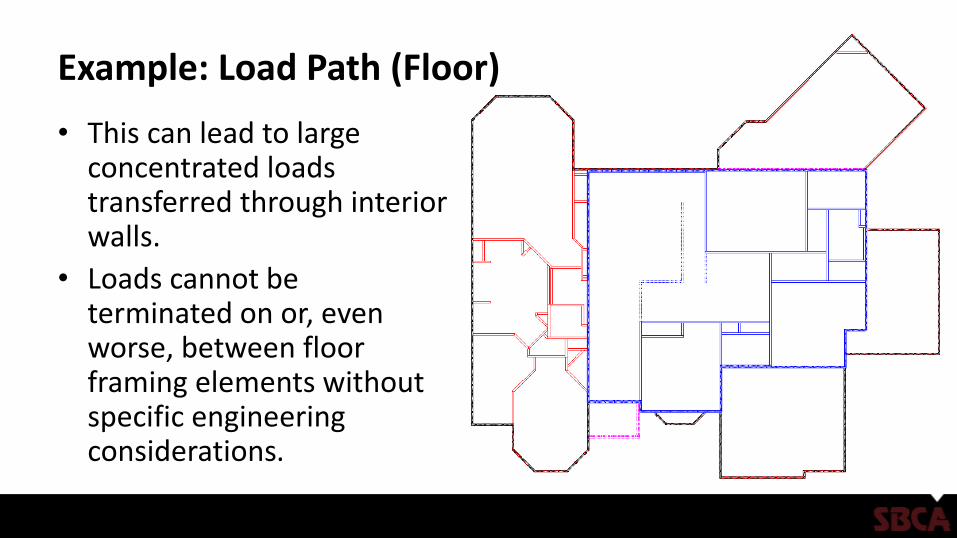
Example: Load Path (Floor)
• This can lead to large concentrated loads transferred through interior walls.
• Loads cannot be terminated on or, even worse, between floor framing elements without specific engineering considerations.
Example: Load Path (Floor)
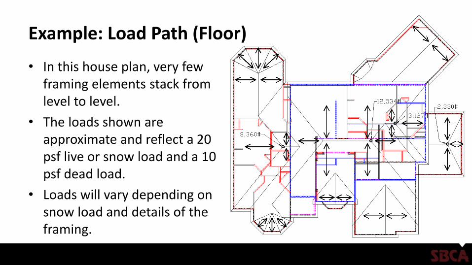
• In this house plan, very few framing elements stack from level to level.
• The loads shown are approximate and reflect a 20 psf live or snow load and a 10 psf dead load.
• Loads will vary depending on snow load and details of the framing.
Example: Load Path (Floor)
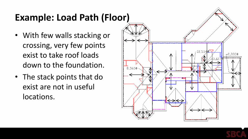
• With few walls stacking or crossing, very few points exist to take roof loads down to the foundation.
• The stack points that do exist are not in useful locations.
Conventional Framing Problem Areas
• Additional areas to watch closely:– Connections
– Supports
– Structural member sizing
Example: Connection (Floor Sag)
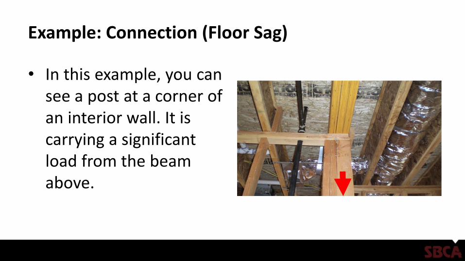
• In this example, you can see a post at a corner of an interior wall. It is carrying a significant load from the beam above.
Example: Connection (Floor Sag)
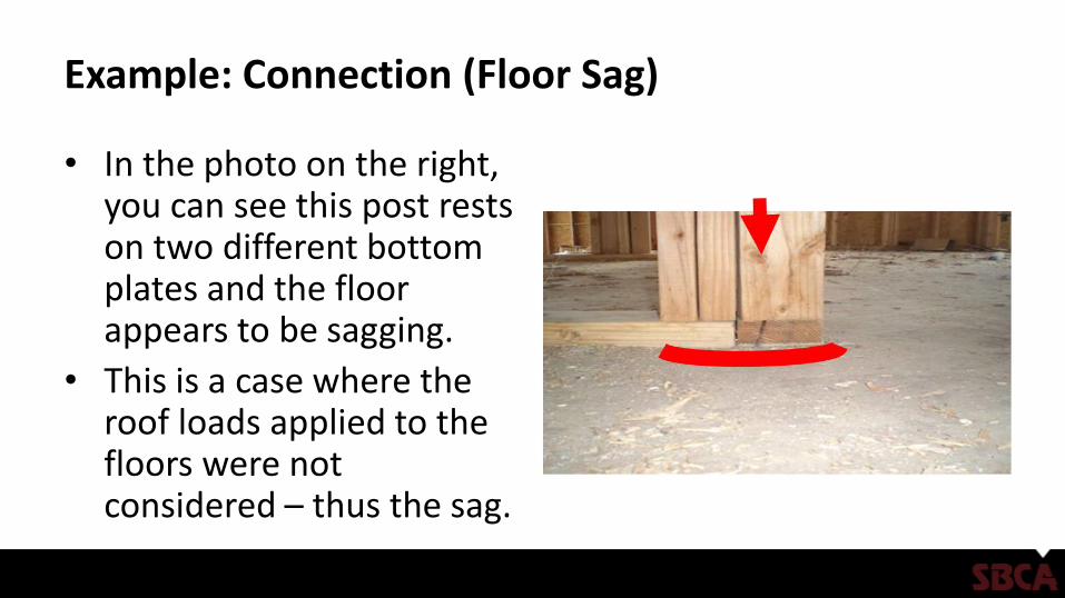
• In the photo on the right, you can see this post rests on two different bottom plates and the floor appears to be sagging.
• This is a case where the roof loads applied to the floors were not considered – thus the sag.
Example: Connection (Floor Sag)
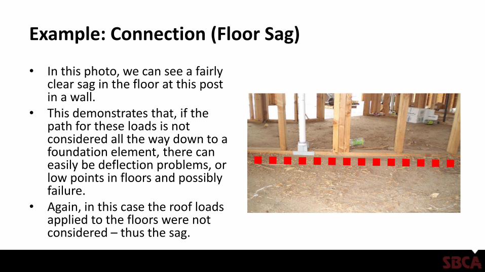
• In this photo, we can see a fairly clear sag in the floor at this post in a wall.
• This demonstrates that, if the path for these loads is not considered all the way down to a foundation element, there can easily be deflection problems, or low points in floors and possibly failure.
• Again, in this case the roof loads applied to the floors were not considered – thus the sag.
Example: Connection (Power Blocking)
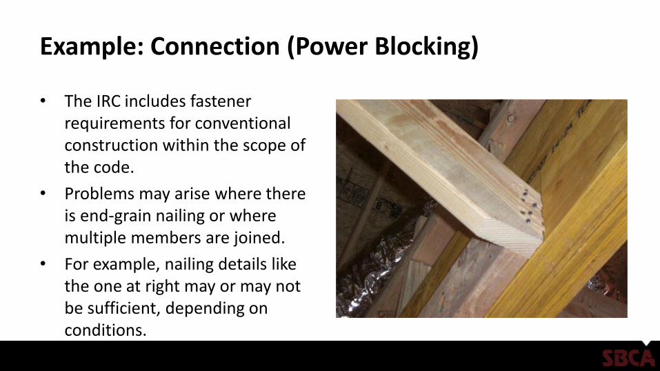
• The IRC includes fastener requirements for conventional construction within the scope of the code.
• Problems may arise where there is end-grain nailing or where multiple members are joined.
• For example, nailing details like the one at right may or may not be sufficient, depending on conditions.
Example: Connection (Power Blocking)
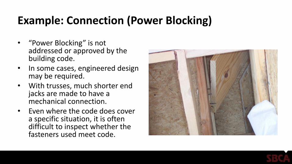
• “Power Blocking” is not addressed or approved by the building code.
• In some cases, engineered design may be required.
• With trusses, much shorter end jacks are made to have a mechanical connection.
• Even where the code does cover a specific situation, it is often difficult to inspect whether the fasteners used meet code.
Example: Connection (Roofs)
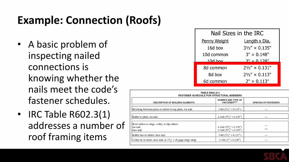
• A basic problem of inspecting nailed connections is knowing whether the nails meet the code’s fastener schedules.
• IRC Table R602.3(1) addresses a number of roof framing items
Example: Connection (Roof Diaphragm)
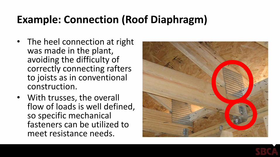
• The heel connection at right was made in the plant, avoiding the difficulty of correctly connecting rafters to joists as in conventional construction.
• With trusses, the overall flow of loads is well defined, so specific mechanical fasteners can be utilized to meet resistance needs.
Example: Connection (Hip Rafters)
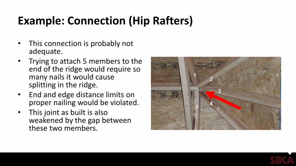
• This connection is probably not adequate.
• Trying to attach 5 members to the end of the ridge would require so many nails it would cause splitting in the ridge.
• End and edge distance limits on proper nailing would be violated.
• This joint as built is also weakened by the gap between these two members.
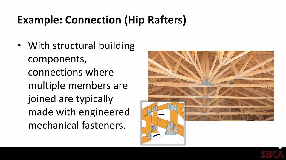
Example: Connection (Hip Rafters)
• With structural building components, connections where multiple members are joined are typically made with engineered mechanical fasteners.
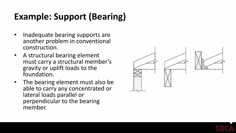
Example: Support (Bearing)
• Inadequate bearing supports are another problem in conventional construction.
• A structural bearing element must carry a structural member’s gravity or uplift loads to the foundation.
• The bearing element must also be able to carry any concentrated or lateral loads parallel or perpendicular to the bearing member.
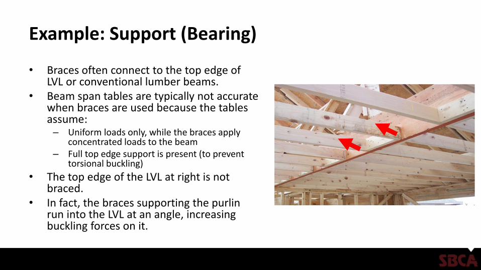
Example: Support (Bearing)
• Braces often connect to the top edge of LVL or conventional lumber beams.
• Beam span tables are typically not accurate when braces are used because the tables assume:– Uniform loads only, while the braces apply
concentrated loads to the beam– Full top edge support is present (to prevent
torsional buckling)
• The top edge of the LVL at right is not braced.
• In fact, the braces supporting the purlin run into the LVL at an angle, increasing buckling forces on it.
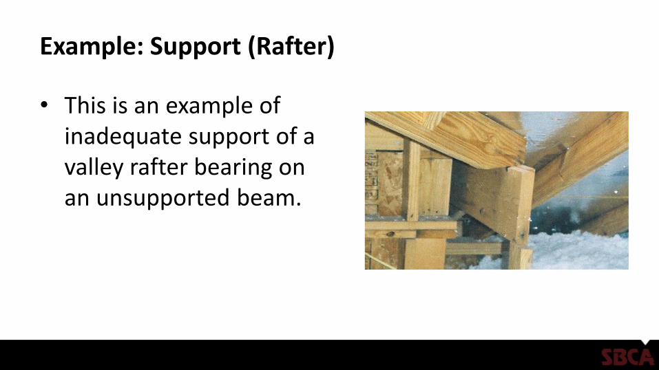
Example: Support (Rafter)
• This is an example of inadequate support of a valley rafter bearing on an unsupported beam.
Example: Support (Rafter)
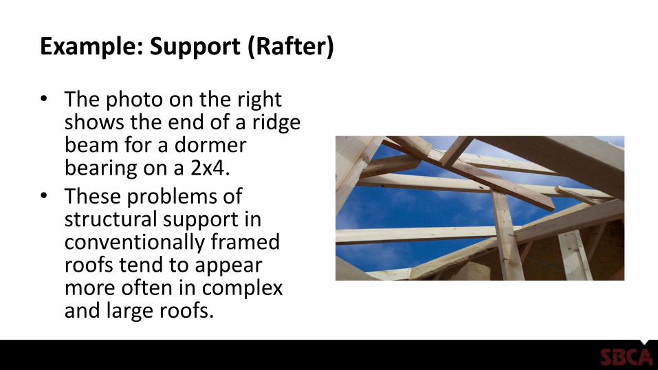
• The photo on the right shows the end of a ridge beam for a dormer bearing on a 2x4.
• These problems of structural support in conventionally framed roofs tend to appear more often in complex and large roofs.
Example: Support (Rafter)
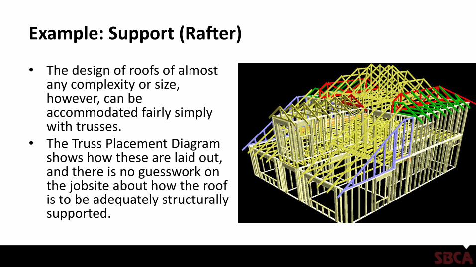
• The design of roofs of almost any complexity or size, however, can be accommodated fairly simply with trusses.
• The Truss Placement Diagram shows how these are laid out, and there is no guesswork on the jobsite about how the roof is to be adequately structurally supported.
Example: Support (Header)
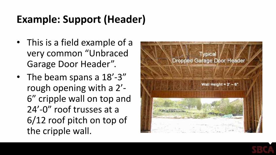
• This is a field example of a very common “Unbraced Garage Door Header”.
• The beam spans a 18’-3” rough opening with a 2’-6” cripple wall on top and 24’-0” roof trusses at a 6/12 roof pitch on top of the cripple wall.
Example: Support (Header)
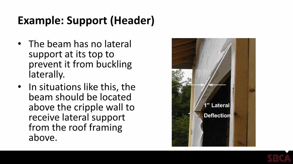
• The beam has no lateral support at its top to prevent it from buckling laterally.
• In situations like this, the beam should be located above the cripple wall to receive lateral support from the roof framing above.
Structural Member Sizing Example
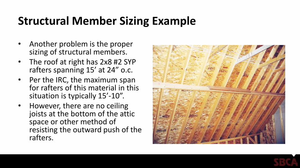
• Another problem is the proper sizing of structural members.
• The roof at right has 2x8 #2 SYP rafters spanning 15’ at 24” o.c.
• Per the IRC, the maximum span for rafters of this material in this situation is typically 15’-10”.
• However, there are no ceiling joists at the bottom of the attic space or other method of resisting the outward push of the rafters.
Structural Member Sizing Example
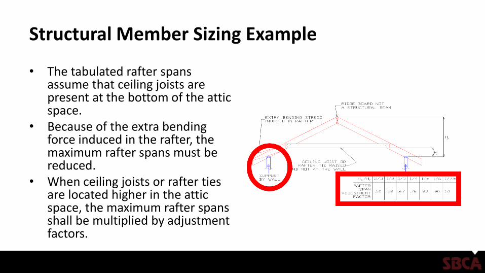
• The tabulated rafter spans assume that ceiling joists are present at the bottom of the attic space.
• Because of the extra bending force induced in the rafter, the maximum rafter spans must be reduced.
• When ceiling joists or rafter ties are located higher in the attic space, the maximum rafter spans shall be multiplied by adjustment factors.
Roofs – Structural Member Sizing
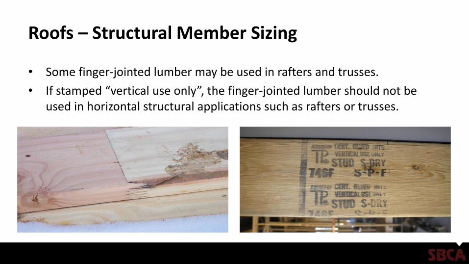
• Some finger-jointed lumber may be used in rafters and trusses.
• If stamped “vertical use only”, the finger-jointed lumber should not be used in horizontal structural applications such as rafters or trusses.
Framing Plan
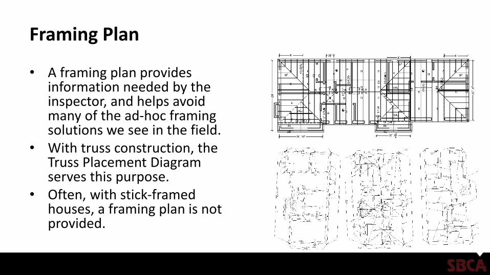
• A framing plan provides information needed by the inspector, and helps avoid many of the ad-hoc framing solutions we see in the field.
• With truss construction, the Truss Placement Diagram serves this purpose.
• Often, with stick-framed houses, a framing plan is not provided.
Findings
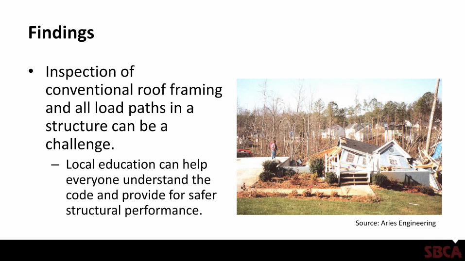
• Inspection of conventional roof framing and all load paths in a structure can be a challenge.– Local education can help
everyone understand the code and provide for safer structural performance.
Source: Aries Engineering
Findings
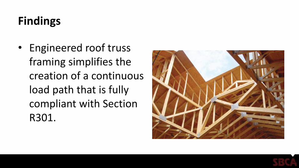
• Engineered roof truss framing simplifies the creation of a continuous load path that is fully compliant with Section R301.
Findings
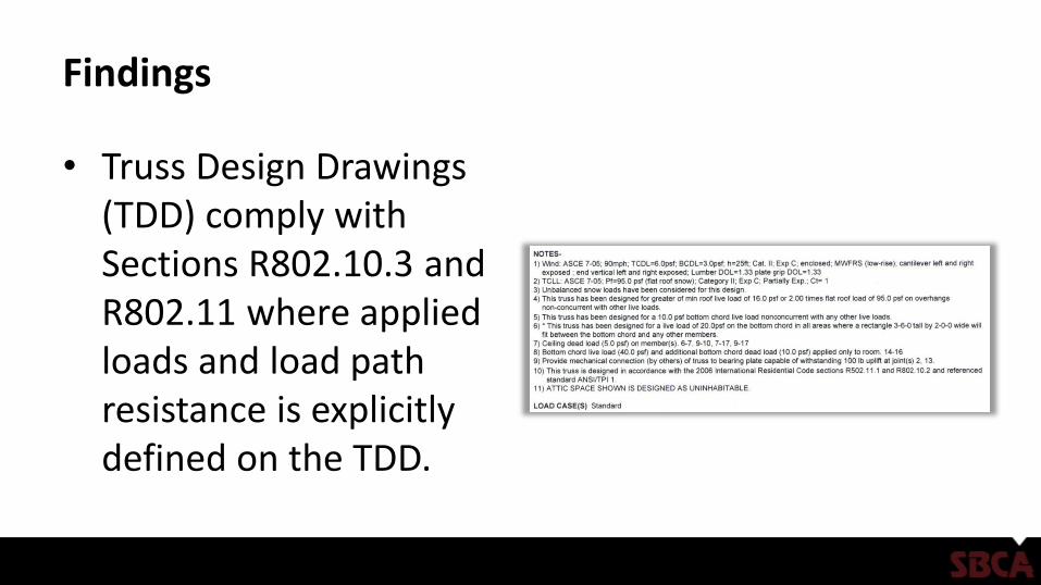
• Truss Design Drawings (TDD) comply with Sections R802.10.3 and R802.11 where applied loads and load path resistance is explicitly defined on the TDD.
Findings
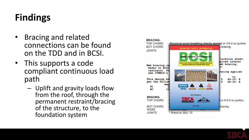
• Bracing and related connections can be found on the TDD and in BCSI.
• This supports a code compliant continuous load path – Uplift and gravity loads flow
from the roof, through the permanent restraint/bracing of the structure, to the foundation system
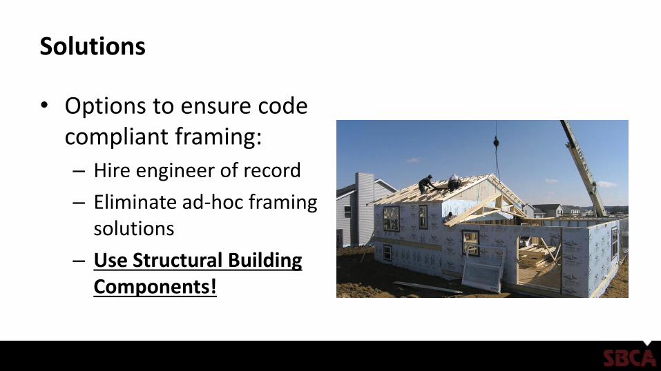
Solutions
• Options to ensure code compliant framing:
– Hire engineer of record
– Eliminate ad-hoc framing solutions
– Use Structural Building Components!
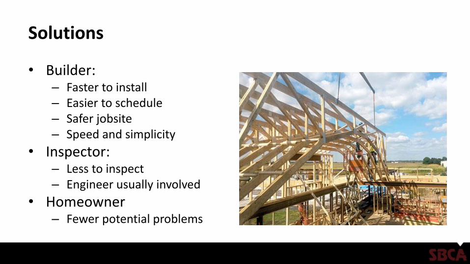
Solutions
• Builder:– Faster to install– Easier to schedule– Safer jobsite– Speed and simplicity
• Inspector:– Less to inspect– Engineer usually involved
• Homeowner– Fewer potential problems
Conclusion
• Using trusses & building components can make IRC code compliance much easier and result in a more structurally accurate and higher quality building.
References
• SRR 1410-02 Code Compliant Construction of Conventionally Framed Roofs and Roof Trusses
• Building Component Safety Information (BCSI): Guide to Good Practice for Handling, Installing & Bracing of Metal Plate Connected Wood Trusses, Structural Building Components Association and Truss Plate Institute, 2013.
• International Residential Code (IRC), International Code Council, 2012.
• TPI 1 – National Design Standard for Metal Plate Connected Wood Truss Construction, Truss Plate Institute, 2007.
• WCD 1 – Details for Conventional Wood Frame Construction, American Wood Council, 2001.
• Wood Frame Construction Manual (WFCM), American Wood Council, 2012.