
IntIntroduction to Plunger Lift inroduction to Plunger Lift Feb 2013

Revision 1.1
1
Code Compliant Anchoring Epoxy Code Compliant Anchoring Epoxy
ASTM C881-10 Type I, II, IV & V Grade 3 Class C
AASHTO M235
Multiple DOT Listings
(See ATC website for current list of Department of Transportation Approvals throughout the
United States and Canada)
ULTRABOND® 365CC is a code compliant, 2-component (3:1 mix ratio by volume) high performance cement and silane hy-brid anchoring system with an extended installation tempera-ture range from 5°F to 104°F (-15°C to 40°C). It has been tested for use with threaded rod and reinforcing bar for cracked and uncracked concrete in accordance with ACI 355.4 and ICC-ES AC308 and has unmatched sustained load resistance up to 194°F (90°C).
Product Description
General Uses & Applications
Anchoring threaded rod and reinforcing bar (rebar) into either cracked or uncracked concrete
Bonding hardened concrete to hardened concrete and freshly mixed concrete to hardened concrete
For use in vertical down, horizontal, upwardly inclined and overhead installations
Resists static, wind and earthquake loading in tension and shear (IBC Seismic Design Categories A-F)
All season hybrid anchoring system for dry, damp and water-saturated concrete
Advantages & Features
CODE COMPLIANT: 2012, 2009 and 2006 IBC/IRC
2014 and 2010 FBC
ASTM C881-14 Type I, II, IV* & V Grade 3
Class A, B & C
AASHTO M235
* Class A & B only
ICC-ES ESR-3770 evaluation report for cracked and uncracked concrete
Allowable Stress Design (ASD) service temperature range between 5°F to 250°F (-15°C to 121°C)
Strength Design (SD) service temperature range between 5°F to 302°F (-15°C to 150°C)
Full cure in 45 minutes @ 77°F (25°C) Resists sustained loads at temperatures up to 194°F (90°C) Moisture insensitive formula allows and curing in damp
water-saturated environments
Withstands freeze-thaw conditions
Low VOC, with virtually no odor, styrene free
High modulus
ESR-3770
Availability: ATC ULTRABOND® products are available through select distributors that can provide all your construction needs. Please contact ATC for a distributor near you.
Color & Ratio: Part A (Resin): Light Gray, Part B (Hardener): Black, Mixed: Gray, Mix Ratio: 3:1
Storage & Shelf Life: 12 months when stored in unopened containers in dry and dark conditions. Store between 41°F (5°C) and 77°F (25°C).
Installation & Coverage: Manufacturer’s Printed Installa-tion Instructions (MPII) are available in this Technical Data Sheet (TDS). Due to occasional updates and revisions, always verify that you are using the most current version of the MPII. In order to achieve maximum results, proper installation is impera-tive.
Chemical Resistance: A Chemical Resistance Chart for ULTRABOND®, MIRACLE BOND® and CRACKBOND® epoxy products is available upon request. Contact a Technical Ser-vice Representative for details.
Clean Up: Clean uncured materials from tools and equip-ment with mild solvents. Cured material can only be removed mechanically.
Limitations & Warnings: Do not thin with solvents, as this will prevent cure
For anchoring applications, concrete should be a minimum of 21 days old prior to anchor installation
Safety: Please refer to the Safety Data Sheet (SDS) for UL-TRABOND 365CC. Call ATC for more information at 1-800-
892-1880.
Specification: Anchoring adhesive shall be a two compo-nent, 3:1 ratio by volume, hybrid anchoring system supplied in pre-measured cartridges. Adhesive must meet the require-ments of C881-14 specification for Type I, II, IV*, and V, Grade 3 Class A, B & C. Adhesive must have a heat deflection tem-perature of 156°F (69°C) per ASTM D648 and have a com-pressive yield strength of 9,380 psi (64.7 MPa) at 75°F (24°C) after a 7 day cure. Adhesive shall be ULTRABOND® 365CC from Adhesives Technology Corp., Pompano Beach, Florida. Anchors shall be installed per the Manufacturer’s Printed Instal-lation Instructions (MPII) for ULTRABOND® 365CC anchoring system.

Revision 1.1
2
Code Compliant Anchoring Epoxy Code Compliant Anchoring Epoxy
ORDERING INFORMATION
TM13-20
Wire Brush (see Tables 5,6,13 & 14 for part #’s)
Brush Extension BR-EXT
Nozzle Extension Tubing TUBE-EXT
11” (280 mm) Large Nozzle
T-365CC-L
8” (205 mm) Small Nozzle T-365CC-S
Manual Brush Handle (comes with wire brush)
SDS Drill Brush Attachment BR-SDS
Small Injection Plugs (order according to hole size)
Large Injection Plug (order according to hole size)
Retention Wedge WEDGE
TABLE 1: ULTRABOND 365CC adhesive, dispensing tools and accessories 1
Package Size
13 oz. (390 ml) 20 oz. (585 ml) Cartridge Cartridge
Part # A13-365CC A20-365CC
Recommended Mixing Nozzle T-365CC-S T-365CC-L
Manual Dispensing Tool TM13-20
Pneumatic Dispensing Tool ---- TA20-F
SDS Brush Adaptor BR-SDS
Brush Extension BR-EXT
Nozzle Extension Tubing TUBE-EXT
Retention Wedge WEDGE
1. Larger 51 oz. (1,500 ml) cartridge size and tools are available as a special order. Please contact ATC repre-sentative for details.
A13-365CC
A20-365CC
13 oz
390 ml
20 oz
585 ml
13 oz
390 ml
20 oz
585 ml
TM - Manual Dispensing Tool Conversion
The TM13-20 manual dispensing tool can easily be converted from the 20 oz. cartridge configuration to the 13 oz. cartridge configuration and back again. Simply loosen the two Philips head screws found on the large plunger enough to slide the plunger from the original setting to the desired size and re-tighten the screw. The cartridge nest will fit both size cartridges without any modifications.

Revision 1.1
3
Code Compliant Anchoring Epoxy Code Compliant Anchoring Epoxy
MATERIAL SPECIFICATION
TABLE 2: ULTRABOND 365CC performance to ASTM C881-14 1
Property Cure Time
ASTM Standard
Units
Sample Conditioning Temperature
Class A Class B Optional Class C
5 °F 50 °F 75 °F 104 °F
(-15) °C (10) °C (24) °C (40) °C
Gel Time - 60 Gram Mass ---- C881 minutes 78 12 5 2
Compressive Yield Strength
7 day
D695
psi 10,730 10,230 9,380 9,260
(MPa) (74.0) (70.5) (64.7) (63.8)
Compressive Modulus
psi 443,100 365,300 377,900 346,200
(MPa) (3,055.1) (2,518.7) (2,605.5) (2,387.0)
Tensile Strength
D638
psi 2,170 1,870 1,720 1,660
(MPa) (15.0) (12.9) (11.9) (11.4)
Tensile Elongation % 0.6 0.6 0.4 0.4
Bond Strength Hardened to Hardened Concrete
2 day
C882
psi 2,530 2,010 2,030 2,260
(MPa) (17.4) (13.9) (14.0) (15.6)
14 day
psi 2,800 2,430 2,240 3,300
(MPa) (19.3) (16.8) (15.4) (22.8)
Bond Strength
Fresh Concrete to Hardened Concrete
psi 2,660
(MPa) (18.3)
Consistency or Viscosity ---- C881 ---- Non-sag
Heat Deflection Temperature 7 day D648
°F 156
(°C) (69.1)
Water Absorption 14 day D570 % 0.90
Linear Coefficient of Shrinkage ---- D2566 % 0.003
Volatile Organic Compounds (VOC's)2
---- E1868 grams/liter 11.0
1. Results based on testing conducted on a representative lot of product. Average results will vary according to the tolerances of the given property. 2. VOC content is outside of the scope of ASTM C881.
TABLE 3: ULTRABOND 365CC CURE SCHEDULE 1,2,3
Base Material Temperature
Working Time Full Cure Time °F
(°C) 5 60 mins 36 hrs (-15)
14 30 mins 24 hrs
(-10) 23 20 mins 8 hrs (-5) 32 13 mins 4 hrs
(0) 41 9 mins 2 hrs
(5) 50 5 mins 1 hrs (10) 68 4 mins 45 mins
(20) 86
2 mins 30 mins
(30) For SI: °F = °C x 9/5 +32
1. Working and full cure times are approximate, may be linearly interpolated between listed temperatures and are based on cartridge/nozzle system perfor-mance. 2. For Temperatures below 41°F, warm the adhesive to a minimum of 41°F, otherwise install adhesive at ambient temperature. 3. Application Temperature: Substrate and ambient air temperature should be from 5 - 104 °F (-15 - 40 °C).

Revision 1.1
4
Code Compliant Anchoring Epoxy Code Compliant Anchoring Epoxy
INSTALLATION INSTRUCTIONS MPII
Drilling and Cleaning
Cartridge Preparation
Installation and Curing (Vertical Down, Horizontal & Overhead)
1
2
3
4
5
6
Using a rotary hammer drill, and a bit which conforms to ANSI B212.15 and is the appropriate size (see Tables 5, 6, 13 & 14) for the anchor diameter to be installed, drill the hole to the specified embedment depth. CAUTION: Always wear ap-propriate personal protection equipment (PPE) for eyes, ears & skin and avoid inhalation of dust during the drilling and cleaning process. Refer to the Safety Data Sheet (SDS) for details prior to proceeding.
NOTE: Remove any standing water from hole prior to beginning the cleaning process. Using oil free com-pressed air with a minimum pressure of 87 psi (6 bar), insert the air wand to the bottom of the drilled hole and blow out the debris with an up/down motion for a minimum of 2 seconds/cycles (2X). For drilled holes <3/4” in diameter, embed-ment depths <10d or in uncracked concrete, a hand pump may be used instead of compressed air.
Select the correct wire brush size for the drilled hole diameter (see Tables 5, 6, 13 & 14), making sure that the brush is long enough to reach the bottom of the drilled hole. Reaching the bottom of the hole (use brush extension if required), brush either manually or with drill motor attachment in an up/down and twisting motion for 2 cycles (2X). CAUTION: The brush should be clean and contact the walls of the hole. If it does not, the brush is either too worn or small and should be replaced with a new brush of the correct diameter.
Blow the hole out once more to remove brush debris using oil free compressed air with a minimum pressure of 87 psi (6 bar). Insert the air wand to the bottom of the drilled hole and blow out the debris with an up/down motion for a minimum of 2 seconds/cycles (2X). Visually inspect the hole to confirm it is clean. NOTE: If installation will be delayed for any reason, cover cleaned holes to prevent contamination.
CAUTION: Check the expiration date on the cartridge to ensure it is not expired. Do not use expired product! Remove the protective cap from the cartridge and insert the cartridge into the recommended dispensing tool (see Table 1). Screw on the proper Adhesives Technology mixing nozzle to the cartridge (see Table 1). Do not modify mixing noz-zle and confirm that internal mixing element is in place prior to dispensing adhesive. Never use without the mixing noz-zle! Take note of the air and base material temperatures, review the working/full cure time chart (see Table 3) and con-dition the cartridge accordingly prior to starting the injection process.
Dispense the initial amount of material from the mixing nozzle onto a disposable surface until the product is a uniform gray color with no streaks, as adhesive must be properly mixed in order to perform as published. Dispose of the initial amount of adhesive according to federal, state and local regulations prior to injection into the drill hole. CAUTION: When changing cartridges, never re-use nozzles. For a new cartridge (or if working time has been exceeded), ensure that cartridge opening is clean, install a new nozzle and repeat steps 5 & 6 accordingly. After finishing work, leave the mixing nozzle attached to the cartridge.
NOTE: The engineering drawings must be followed. For any applications not covered by this document, or if there are any installation questions, please contact Adhesives Technology Corp. Insert the mixing nozzle, using an extension tube if hole depth > 6" (150mm), to the bottom of the hole and fill from the bottom to the top approximately 2/3 full, being careful not to withdraw the nozzle too quickly as this may trap air in the adhesive.
Injection plugs should be used for overhead installations, drill hole diameters > 1-1/8" (30 mm) or drill hole depths > 10" (250 mm). Select the proper injection plug for the drill hole diameter as given in Tables 5, 6, 13 & 14. The injection plug fits directly onto the tip of small mixing nozzle. For the large mixing nozzle extension tubing must be used in con-junction with the injection plug.
If extension tubing is needed, it can be connected onto the outside of the tip of the smaller mixing nozzle (part# T-365CC -S) and fits inside of the tip of the larger mixing nozzle (part# T-365CC-L). NOTE: When using a pneumatic dispensing tool, ensure that pressure is set at 90 psi (6.2 bar) maximum.
Revision 1.1
5
Code Compliant Anchoring Epoxy Code Compliant Anchoring Epoxy
INSTALLATION INSTRUCTIONS MPII
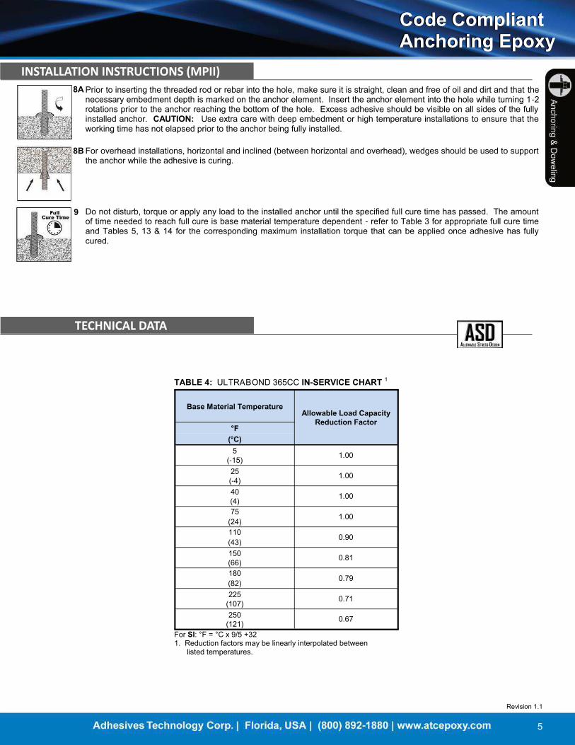
Prior to inserting the threaded rod or rebar into the hole, make sure it is straight, clean and free of oil and dirt and that the necessary embedment depth is marked on the anchor element. Insert the anchor element into the hole while turning 1-2 rotations prior to the anchor reaching the bottom of the hole. Excess adhesive should be visible on all sides of the fully installed anchor. CAUTION: Use extra care with deep embedment or high temperature installations to ensure that the working time has not elapsed prior to the anchor being fully installed.
8A
9 Do not disturb, torque or apply any load to the installed anchor until the specified full cure time has passed. The amount of time needed to reach full cure is base material temperature dependent - refer to Table 3 for appropriate full cure time and Tables 5, 13 & 14 for the corresponding maximum installation torque that can be applied once adhesive has fully cured.
8B For overhead installations, horizontal and inclined (between horizontal and overhead), wedges should be used to support the anchor while the adhesive is curing.
TECHNICAL DATA
TABLE 4: ULTRABOND 365CC IN-SERVICE CHART 1
Base Material Temperature
Allowable Load Capacity Reduction Factor
°F
(°C) 5 1.00 (-15) 25 1.00
(-4) 40 1.00
(4) 75 1.00
(24) 110 0.90
(43) 150 0.81
(66) 180 0.79
(82) 225 0.71
(107) 250 0.67
(121) For SI: °F = °C x 9/5 +32
1. Reduction factors may be linearly interpolated between
listed temperatures.

Revision 1.1
6
Code Compliant Anchoring Epoxy Code Compliant Anchoring Epoxy
TECHNICAL DATA
TABLE 5: ULTRABOND 365CC INCH THREADED ROD installation parameters, brushes, and injection plugs
Threaded Rod
Diameter in.
Drill Bit Diameter
in.
Maximum Installation
Torque ft-lbs. (N-m)
Nominal Brush
Diameter in.
Brush Part #
Brush Qty. Injection Plug Part #
Injection Plug Color
Injection Plug Qty.
3/8 7/16 14 (19.9) 1/2 BR716 1 ---- ---- ----
1/2 9/16 29 (39.3) 5/8 BR916 1 IP12-916 Blue 1
5/8 3/4 44 (59.7) 1 BR34-78 1 IP34-78 Green 1 3/4 7/8 88 (119.3) 7/8 1 110 (149.1) 1 1/8 BR100 1 IP100 Black 1
1 1 1/8 147 (199.3) 1 3/16 BR118 1 IP118 Gray 1
1 1/4 1 3/8 221 (299.6) 1 1/2 BR138-112 1 IP138 Brown 1
TABLE 6: ULTRABOND 365CC INCH REBAR installation parameters, brushes, and injection plugs
Rebar Diameter
in.
Drill Bit Diameter
in.
Nominal Brush
Diameter in.
Brush Part #
Brush Qty. Injection Plug Part #
Injection Plug Color
Injection Plug Qty.
#3 1/2 1/2 BR12 1 IP12-916 Blue 1
#4 5/8 5/8 BR58 1 IP58 Red 1
#5 3/4 1 BR34-78 1 IP34-78 Green 1 #6 7/8 #7 1 1 1/8 BR100 1 IP100 Black 1
#8 1 1/8 1 3/16 BR118 1
IP118 Gray 1
#9 1 3/8 IP138 Brown 1
#10 1 1/2 1 1/2 BR138-112 1 IP112 Clear 1
TABLE 7: ULTRABOND 365CC ultimate and allowable TENSION loads for THREADED ROD in normal-weight concrete 1,2
Threaded Rod Diameter
in.
Nominal Drill Bit
Diameter in.
Embedment Depth
in. (mm)
Tension Load Based on Bond Strength/Concrete Capacity
Allowable Tension Load Based on Steel Strength3
f'c ≥ 2,500 psi (17.4 MPa) ASTM F1554
Grade 36
lbs. (kN)
ASTM A193
Grade B7
lbs. (kN)
ASTM F593
304/316 SS
lbs. (kN)
Ultimate
lbs. (kN) Allowable
lbs. (kN)
3/8 7/16
1 11/16 4,060 1,015
2,114 4,556 3,645
(43) (18.1) (4.5)
3 3/8 9,941 2,485 (9.4) (20.3) (16.2)
(86) (44.2) (11.1)
1/2 9/16
2 1/4 6,276 1,569
3,758 8,099 6,480
(57) (27.9) (7.0)
4 1/2 16,427 4,107 (16.7) (36.0) (28.8)
(114) (73.1) (18.3)
5/8 3/4
2 13/16 8,534 2,134
5,872 12,655 10,124
(71) (38.0) (9.5)
5 5/8 22,072 5,518 (26.1) (56.3) (45.0)
(143) (98.2) (24.5)
3/4 7/8
3 3/8 12,294 3,074
8,456 18,224 12,392
(86) (54.7) (13.7)
6 3/4 33,026 8,257 (37.6) (81.1) (55.1)
(171) (146.9) (36.7)
7/8 1
3 15/16 16,823 4,206
11,509 24,804 16,867
(100) (74.8) (18.7)
7 7/8 43,508 10,877 (51.2) (110.3) (75.0)
(200) (193.5) (48.4)
1 1 1/8
4 1/2 20,536 5,134
15,033 32,398 22,030
(114) (91.3) (22.8)
9 53,111 13,278 (66.9) (144.1) (98.0)
(229) (236.2) (59.1)
1 1/4 1 3/8
5 5/8 20,887 5,222
23,488 50,621 34,423
(143) (92.9) (23.2)
11 1/4 54,019 13,505 (104.5) (225.2) (153.1)
(286) (240.3) (60.1)
For SI: 1 inch = 25.4 mm, 1lbf = 4.448 N, 1 psi = 0.006897 MPa. For pound-inch units: 1 mm = 0.03937 inch, 1 N = 0.2248 lbf, 1MPa = 145.0 psi 1. Allowable bond strength/concrete capacity was calculated using a safety factor of 4.0. 2. The lower value of either the allowable bond strength/concrete capacity or steel strength should be used as the allowable tension value for design. 3. Allowable steel strengths calculated in accordance with AISC Manual of Steel Construction: Tensile = 0.33*Fu*Anom.

Revision 1.1
7
Code Compliant Anchoring Epoxy Code Compliant Anchoring Epoxy
TECHNICAL DATA
TABLE 8: ULTRABOND 365CC 4.5D reduction factors for EDGE DISTANCE in TENSION 1,2,3
Diameter in. 3/8 1/2 5/8 3/4 7/8 1 1 1/4 Embedment
Depth
in. 1 3/4 2 1/4 2 7/8 3 3/8 4 4 1/2 5 5/8 (mm) (44) (57) (73) (86) (102) (114) (143)
Critical Edge Distance
in. 3 1/8 4 5 5 7/8 7 7 7/8 9 7/8
(mm) (79) (102) (127) (149) (178) (200) (251) Min. Edge Distance
in. 1 3/8 1 3/4 2 1/8 2 1/2 3 3 3/8 4 1/4
(mm) (35) (44) (54) (64) (76) (86) (108) Edge Distance Tension Multiplier Table in. (mm)
1 3/8 (34.9) 0.73
1 3/4 (44.5) 0.79 0.73
2 1/8 (54.0) 0.84 0.77 0.73
2 1/4 (57.2) 0.86 0.79 0.74
2 1/2 (63.5) 0.90 0.82 0.76 0.73
3 (76.2) 0.98 0.88 0.81 0.77 0.73
3 1/8 (79.4) 1.00 0.89 0.82 0.78 0.74
3 3/8 (85.7) 0.92 0.85 0.80 0.75 0.73
3 1/2 (88.9) 0.94 0.86 0.81 0.76 0.74
3 3/4 (95.3) 0.97 0.88 0.83 0.78 0.75
4 (101.6) 1.00 0.91 0.85 0.80 0.77
4 1/4 (108.0) 0.93 0.87 0.81 0.78 0.73
4 3/4 (120.7) 0.98 0.91 0.85 0.81 0.75
5 (127.0) 1.00 0.93 0.86 0.83 0.76
5 3/4 (146.1) 0.99 0.91 0.87 0.80
5 7/8 (149.2) 1.00 0.92 0.88 0.81
6 1/2 (165.1) 0.97 0.92 0.84
7 (177.8) 1.00 0.95 0.86
7 1/2 (190.5) 0.98 0.89
7 7/8 (200.0) 1.00 0.90
8 1/2 (215.9) 0.93
9 1/4 (235.0) 0.97
9 7/8 (250.8) 1.00
TABLE 9: ULTRABOND 365CC 9D reduction factors for EDGE DISTANCE in TENSION 1,2,3
Diameter in. 3/8 1/2 5/8 3/4 7/8 1 1 1/4 Embedment
Depth
in. 3 3/8 4 1/2 5 5/8 6 3/4 7 7/8 9 11 1/4 (mm) (86) (114) (143) (171) (200) (229) (286)
Critical Edge Distance
in. 6 7 7/8 9 7/8 11 7/8 13 7/8 15 3/4 19 3/4 (mm) (152) (200) (251) (302) (352) (400) (502)
Min. Edge Distance
in. 1 3/4 2 1/4 2 3/4 3 1/2 4 4 1/2 5 3/4 (mm) (44) (57) (70) (89) (102) (114) (146)
Edge Distance Tension Multiplier Table in. (mm) 1 3/4 (44.5) 0.55
2 1/4 (57.2) 0.60 0.55
2 3/4 (69.9) 0.66 0.59 0.55
3 (76.2) 0.68 0.61 0.57
3 1/2 (88.9) 0.74 0.65 0.60 0.55
4 (101.6) 0.79 0.69 0.63 0.58 0.55
4 1/2 (114.3) 0.84 0.73 0.66 0.61 0.57 0.55
5 (127.0) 0.89 0.77 0.69 0.63 0.60 0.57
5 3/4 (146.1) 0.97 0.83 0.74 0.67 0.63 0.60 0.55
6 (152.4) 1.00 0.85 0.76 0.69 0.64 0.61 0.56
7 (177.8) 0.93 0.82 0.74 0.69 0.65 0.59
7 7/8 (200.0) 1.00 0.87 0.79 0.73 0.69 0.63
9 (228.6) 0.94 0.85 0.78 0.73 0.66
9 7/8 (250.8) 1.00 0.89 0.82 0.77 0.69
10 (254.0) 0.90 0.82 0.77 0.70
11 7/8 (301.6) 1.00 0.91 0.85 0.76
12 1/2 (317.5) 0.94 0.87 0.78
13 7/8 (352.4) 1.00 0.93 0.82
15 (381.0) 0.97 0.86
15 3/4 (400.1) 1.00 0.88
17 (431.8) 0.92
18 1/4 (463.6) 0.96
19 3/4 (501.7) 1.00
For SI: 1 inch = 25.4 mm, 1lbf = 4.448 N, 1 psi = 0.006897 MPa. For pound-inch units: 1 mm = 0.03937 inch, 1 N = 0.2248 lbf, 1MPa = 145.0 psi 1. Minimum slab thickness equals 1.5 x embedment depth. 2. For embedment depth less than listed in Table 9 and greater than listed above use reduction in this table. Linear interpolation may be used for intermediate edge distances. 3. D Refers to the diameter of the rod or bolt.
For SI: 1 inch = 25.4 mm, 1lbf = 4.448 N, 1 psi = 0.006897 MPa. For pound-inch units: 1 mm = 0.03937 inch, 1 N = 0.2248 lbf, 1MPa = 145.0 psi 1. Minimum slab thickness equals 1.5 x embedment depth. 2. For embedment depth equal to or larger than listed above, use the reduc-tion factors listed in this table. Linear interpolation may be used for interme-diate edge distances. 3. D Refers to the diameter of the rod or bolt.

Revision 1.1
8
Code Compliant Anchoring Epoxy Code Compliant Anchoring Epoxy
TECHNICAL DATA
TABLE 10: ULTRABOND 365CC 4.5D reduction factors for SPACING DISTANCE in TENSION 1,2,3
Diameter in. 3/8 1/2 5/8 3/4 7/8 1 1 1/4 Embedment
Depth
in. 1 3/4 2 1/4 2 7/8 3 3/8 4 4 1/2 5 5/8 (mm) (44) (57) (73) (86) (102) (114) (143)
Critical Spacing Distance
in. 3 1/2 4 1/2 5 3/4 6 3/4 8 9 11 1/4 (mm) (89) (114) (146) (171) (203) (229) (286)
Min. Spacing Distance
in. 7/8 1 1/8 1 1/2 1 3/4 2 2 1/4 2 3/4 (mm) (22) (29) (38) (44) (51) (57) (70)
Spacing Distance Tension Multiplier Table in. (mm) 7/8 (22.2) 0.57
1 1/8 (28.6) 0.61 0.57
1 1/2 (38.1) 0.68 0.62 0.57
1 5/8 (41.3) 0.70 0.64 0.59
1 3/4 (44.5) 0.72 0.65 0.60 0.57
2 (50.8) 0.76 0.68 0.62 0.60 0.57
2 1/4 (57.2) 0.80 0.72 0.65 0.62 0.59 0.57
2 3/4 (69.9) 0.88 0.78 0.70 0.66 0.63 0.61 0.57
3 1/2 (88.9) 1.00 0.87 0.77 0.72 0.68 0.65 0.61
4 (101.6) 0.94 0.82 0.77 0.72 0.68 0.64
4 1/2 (114.3) 1.00 0.87 0.81 0.75 0.72 0.66
5 (127.0) 0.92 0.85 0.79 0.75 0.69
5 3/4 (146.1) 1.00 0.91 0.84 0.80 0.72
6 1/4 (158.8) 0.96 0.88 0.83 0.75
6 3/4 (171.5) 1.00 0.91 0.86 0.77
7 1/4 (184.2) 0.95 0.89 0.80
8 (203.2) 1.00 0.94 0.84
8 1/2 (215.9) 0.97 0.86
9 (228.6) 1.00 0.89
9 1/2 (241.3) 0.91
10 (254.0) 0.94
10 1/2 (266.7) 0.96
TABLE 11: ULTRABOND 365CC 9D reduction factors for SPACING DISTANCE in TENSION 1,2,3
Diameter in. 3/8 1/2 5/8 3/4 7/8 1 1 1/4 Embedment
Depth
in. 3 3/8 4 1/2 5 5/8 6 3/4 7 7/8 9 11 1/4 (mm) (86) (114) (143) (171) (200) (229) (286)
Critical Spacing Distance
in. 6 3/4 9 11 1/4 13 1/2 15 3/4 18 22 1/2 (mm) (171) (229) (286) (343) (400) (457) (572)
Min. Spacing Distance
in. 1 3/4 2 1/4 2 3/4 3 1/2 4 4 1/2 5 3/4 (mm) (44) (57) (70) (89) (102) (114) (146)
Spacing Distance Tension Multiplier Table in. (mm) 1 3/4 (44.5) 0.62
2 1/4 (57.2) 0.66 0.62
2 3/4 (69.9) 0.70 0.65 0.62
3 (76.2) 0.72 0.66 0.63
3 1/2 (88.9) 0.75 0.69 0.65 0.62
4 (101.6) 0.79 0.72 0.68 0.64 0.62
4 1/2 (114.3) 0.83 0.75 0.70 0.66 0.64 0.62
5 3/4 (146.1) 0.92 0.82 0.75 0.71 0.68 0.66 0.62
6 3/4 (171.5) 1.00 0.87 0.80 0.74 0.71 0.68 0.64
7 1/2 (190.5) 0.92 0.83 0.77 0.73 0.71 0.66
8 1/4 (209.6) 0.96 0.87 0.80 0.76 0.73 0.68
9 (228.6) 1.00 0.90 0.83 0.78 0.75 0.69
10 (254.0) 0.94 0.87 0.81 0.78 0.72
11 1/4 (285.8) 1.00 0.91 0.85 0.81 0.75
12 1/4 (311.2) 0.95 0.89 0.84 0.77
13 1/2 (342.9) 1.00 0.93 0.87 0.80
14 1/2 (368.3) 0.96 0.90 0.82
15 3/4 (400.1) 1.00 0.94 0.85
16 3/4 (425.5) 0.96 0.87
18 (457.2) 1.00 0.90
19 (482.6) 0.92
20 1/2 (520.7) 0.95
22 1/2 (571.5) 1.00
For SI: 1 inch = 25.4 mm, 1lbf = 4.448 N, 1 psi = 0.006897 MPa. For pound-inch units: 1 mm = 0.03937 inch, 1 N = 0.2248 lbf, 1MPa = 145.0 psi 1. Minimum slab thickness equals 1.5 x embedment depth. 2. For embedment depth less than listed in Table 11 and greater than listed above use reduction in this table. Linear interpolation may be used for intermediate edge distances. 3. D Refers to the diameter of the rod or bolt.
For SI: 1 inch = 25.4 mm, 1lbf = 4.448 N, 1 psi = 0.006897 MPa. For pound-inch units: 1 mm = 0.03937 inch, 1 N = 0.2248 lbf, 1MPa = 145.0 psi 1. Minimum slab thickness equals 1.5 x embedment depth. 2. For embedment depth equal to or larger than listed above, use the reduc-tion factors listed in this table. Linear interpolation may be used for interme-diate edge distances. 3. D Refers to the diameter of the rod or bolt.

Revision 1.1
9
Code Compliant Anchoring Epoxy Code Compliant Anchoring Epoxy
TECHNICAL DATA
TABLE 13: ULTRABOND 365CC METRIC THREADED ROD installation parameters, brushes, and injection plugs
Threaded Rod
Diameter
Drill Bit Di-ameter mm
(in.)
Maximum In-stallation Torque
N-m (ft-lbs.)
Nominal Brush
Diameter in.
Brush Part #
Brush Qty. Injection Plug Part #
Injection Plug Color
Injection Plug Qty.
M8 10 (3/8) 10 (7) 1/2 BR716 1 ---- ---- ----
M10 12 (1/2) 20 (15) 5/8 BR12 1 IPM12 Clear 1
M12 14 (9/16) 40 (30) 3/4 BR916 1 IP12-916 Blue 1
M16 18 (11/16) 60 (44) 7/8 BR58 1 IPM18 Yellow 1
M20 24 (1) 120 (89) 1 1/8 BR100 1 IPM24 Brown 1
M24 28 (1 1/8) 150 (111) 1 3/16 BR118 1 IPM28 Blue 1
M30 35 (1 3/8) 300 (221) 1 1/2 BR138-112 1 IP138 Brown 1
TABLE 14: ULTRABOND 365CC METRIC REBAR installation parameters, brushes, and injection plugs
Rebar Diameter
mm
Drill Bit Di-ameter
mm (in.)
Maximum In-stallation Torque
N-m (ft-lbs.)
Nominal Brush
Diameter in.
Brush Part #
Brush Qty. Injection Plug Part #
Injection Plug Color
Injection Plug Qty.
8 12 (1/2) 10 (7.35) 1/2 BR12 1 IPM12 Clear 1
16 20 (13/16) 20 (14.75) 1 BR34-78 1 IP34-78 Green 1
32 40 (1 1/2) 40 (29.5) 1 5/8 BRM40 1 IP112 Clear 1
TECHNICAL DATA
TABLE 12: ULTRABOND 365CC ultimate and allowable TENSION & SHEAR loads for REBAR in normal-weight concrete 1,2
Rebar Size
in.
Nominal Drill Bit Diameter
in.
Embedment Depth
in. (mm)
Tension Load Based on Bond Strength/Concrete Capacity
Allowable Load Based on Steel Strength3
f'c ≥ 3,000 psi (20.7 MPa) Tension Shear
Ultimate
lbs. (kN) Allowable
lbs. (kN)
ASTM A615
Grade 60
lbs. (kN)
ASTM A615
Grade 75
lbs. (kN)
ASTM A615
Grade 60
lbs. (kN)
ASTM A615
Grade 75
lbs. (kN)
#3 1/2
3 3/8 6,072 1,518 2,640 3,300 1,683 1,870
(86) (27.0) (6.8) (11.7) (14.7) (7.5) (8.3)
#4 5/8
4 1/2 11,928 2,982 4,800 6,000 3,060 3,400
(114) (53.1) (13.3) (21.4) (26.7) (13.6) (15.1)
#5 3/4
5 5/8 18,326 4,581 7,440 9,300 4,743 5,270
(143) (81.5) (20.4) (33.1) (41.4) (21.1) (23.4)
#6 7/8
6 3/4 25,789 6,447 10,560 13,200 6,732 7,480
(171) (114.7) (28.7) (47.0) (58.7) (29.9) (33.3)
#7 1
7 7/8 31,224 7,806 14,400 18,000 9,180 10,200
(200) (138.9) (34.7) (64.1) (80.1) (40.8) (45.4)
#8 1 1/8
9 40,783 10,196 18,960 23,700 12,087 13,430
(229) (181.4) (45.4) (84.3) (105.4) (53.8) (59.7)
#10 1 3/8
11 1/4 52,315 13,079 30,480 38,100 19,431 21,590
(286) (232.7) (58.2) (135.6) (169.5) (86.4) (96.0) For SI: 1 inch = 25.4 mm, 1lbf = 4.448 N, 1 psi = 0.006897 MPa. For pound-inch units: 1 mm = 0.03937 inch, 1 N = 0.2248 lbf, 1MPa = 145.0 psi 1. Allowable bond strength/concrete capacity was calculated using a safety factor of 4.0. 2. The lower value of either the allowable bond strength/concrete capacity or steel strength should be used as the allowable tension or shear value for design. 3. Allowable steel strengths calculated in accordance with AISC Manual of Steel Construction: Tensile = (Fy*Anom)/2.5, Shear = 0.17*Fu*Anom.

Revision 1.1
10
Code Compliant Anchoring Epoxy Code Compliant Anchoring Epoxy
TECHNICAL DATA
TABLE 15: ULTRABOND 365CC STEEL design information for METRIC THREADED ROD 1
Characteristic Symbol Units
Threaded Rod Size
M8 M10 M12 M16 M20 M24 M30
Nominal Anchor Diameter d mm 8 10 12 16 20 24 30
(in.) (0.31) (0.39) (0.47) (0.63) (0.79) (0.94) (1.18)
Threaded Rod Cross-Sectional Area
Ase
mm2 36.6 58.0 84.3 156.7 244.8 352.5 560.7
(in.2) (0.057) (0.090) (0.131) (0.243) (0.379) (0.546) (0.869)
Nominal Strength as Governed by Steel
Strength
Nsa
kN 18.3 29.0 42.2 78.4 122.4 176.3 280.4
(lb) (4,114) (6,520) (9,476) (17,615) (27,518) (39,625) (63,028)
Vsa
kN 11.0 17.4 25.3 47.0 73.4 105.8 168.2
(lb) (2,469) (3,912) (5,686) (10,569) (16,511) (23,775) (37,817)
Reduction Factor for Seismic Shear αV,seis ----
Not Applicable
1.0 0.87
Strength Reduction
Factor for Tension2 ɸ ---- 0.65
Strength Reduction
Factor for Shear2 ɸ ---- 0.60
Nominal Strength as Governed by Steel
Strength
Nsa
kN 29.3 46.4 67.4 125.4 195.8 282.0 448.6
(lb) (6,583) (10,432) (15,162) (28,183) (44,029) (63.399) (100,845)
Vsa
kN 17.6 27.8 40.5 75.2 117.5 169.2 269.1
(lb) (3,950) (6,259) (9,097) (16,910) (26,417) (38,040) (60,507)
Reduction Factor for Seismic Shear αV,seis ----
Not Applicable
0.90
Strength Reduction
Factor for Tension2 ɸ ---- 0.65
Strength Reduction
Factor for Shear2 ɸ ---- 0.60
Nominal Strength as Governed by Steel
Strength
Nsa
kN 25.6 40.6 59.0 109.7 171.4 246.8 392.5
(lb) (5,760) (9,128) (13,267) (24,661) (38,525) (55,474) (88,240)
Vsa
kN 15.4 24.4 35.4 65.8 102.8 148.1 235.5
(lb) (3,456) (5,477) (7,960) (14,796) (23,115) (33,285) (52,944)
Reduction Factor for Seismic Shear αV,seis ----
Not Applicable
0.90
Strength Reduction
Factor for Tension2 ɸ ---- 0.65
Strength Reduction
Factor for Shear2 ɸ ---- 0.60
Nominal Strength as Governed by Steel
Strength
Nsa
kN 29.3 46.4 67.4 125.4 195.8 282.0 448.6
(lb) (6,583) (10,432) (15,162) (28,183) (44,029) (63,399) (100,845)
Vsa
kN 17.6 27.8 40.5 75.2 117.5 169.2 269.1
(lb) (3,950) (6,259) (9,097) (16,910) (26,417) (38,040) (60,507)
Reduction Factor for Seismic Shear αV,seis ----
Not Applicable
0.90
Strength Reduction
Factor for Tension2 ɸ ---- 0.65
Strength Reduction
Factor for Shear2 ɸ ---- 0.60
For SI: 1 inch = 25.4 mm, 1lbf = 4.448 N, 1 psi = 0.006897 MPa. For pound-inch units: 1 mm = 0.03937 inch, 1 N = 0.2248 lbf, 1MPa = 145.0 psi. 1. Values provided for common rod material types are based on specified strength and calculated in accordance with ACI 318-11 Eq. (D-2) and Eq. (D-29). Nuts and washers must be appropriated for the rod strength and type. 2. For use with load combinations of IBC Section 1605.2 or ACI 318 9.2 as set forth in ACI 318 D.4.3. If the load combinations of ACI 318 Appendix C is used, the appropriate value of ɸ must be determined in accordance with ACI 318 D4.4. Values correspond to a brittle steel element.
ISO
898
-1
Cla
ss 8
.8
ISO
898
-1
Cla
ss 5
.8
ISO
350
6-1
Cla
ss A
4-70
and
Stai
nles
s C
-70
ISO
350
6-1
Cla
ss A
4-80
and
Stai
nles
s C
-80
Revision 1.1
11
Code Compliant Anchoring Epoxy Code Compliant Anchoring Epoxy
TECHNICAL DATA
4.1;7.01.3max
1160
;min4.0
max,,
ef
kuncrkfeac h
hhC
4.1;7.01.3max
8
;min4.0
max,,
ef
kuncrkfeac h
hhC
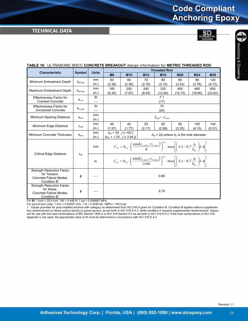
TABLE 16: ULTRABOND 365CC CONCRETE BREAKOUT design information for METRIC THREADED ROD
Characteristic Symbol Units
Threaded Rod
M8 M10 M12 M16 M20 M24 M30
Minimum Embedment Depth hef,min
mm 60 60 70 80 90 96 120
(in.) (2.36) (2.36) (2.76) (3.15) (3.54) (3.78) (4.72)
Maximum Embedment Depth hef,max
mm 160 200 240 320 400 480 600
(in.) (6.30) (7.87) (9.45) (12.60) (15.75) (18.90) (23.62)
Effectiveness Factor for Cracked Concrete
kc,cr SI 7.1
---- (17)
Effectiveness Factor for Uncracked Concrete
kc,uncr SI 10
---- (24)
Minimum Spacing Distance smin
mm Smin= Cmin
(in.)
Minimum Edge Distance cmin
mm 40 45 55 65 85 105 140
(in.) (1.57) (1.77) (2.17) (2.56) (3.35) (4.13) (5.51)
Minimum Concrete Thickness hmin
mm hef + 30 , [ ≥ 100 ] hef + 2d0 where do is the hole diameter (in.) (hef + 1.25 , [ ≥ 3.94 ])
Critical Edge Distance cac
mm
in.
Strength Reduction Factor for Tension,
Concrete Failure Modes, Condition B1
ɸ ---- 0.65
Strength Reduction Factor for Shear,
Concrete Failure Modes, Condition B1
ɸ ---- 0.70
For SI: 1 inch = 25.4 mm, 1lbf = 4.448 N, 1 psi = 0.006897 MPa. For pound-inch units: 1 mm = 0.03937 inch, 1 N = 0.2248 lbf, 1MPa = 145.0 psi 1. Values provided for post-installed anchors with category as determined from ACI 355.4 given for Condition B. Condition B applies without supplemen-tary reinforcement or where pullout (bond) or pryout govern, as set forth in ACI 318 D.4.3, while condition A requires supplemental reinforcement. Values are for use with the load combinations of IBC Section 1605.2 or ACI 318 Section 9.2 as set forth in ACI 318 D.4.3. If the load combinations of ACI 318 Appendix C are used, the appropriate value of Ф must be determined in accordance with ACI 318 D.4.4.
Revision 1.1
12
Code Compliant Anchoring Epoxy Code Compliant Anchoring Epoxy
TECHNICAL DATA
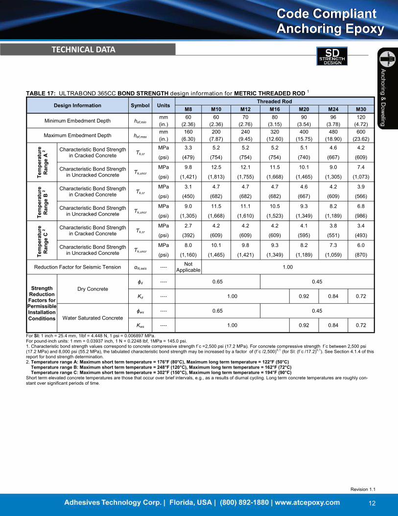
TABLE 17: ULTRABOND 365CC BOND STRENGTH design information for METRIC THREADED ROD 1
Design Information Symbol Units
Threaded Rod
M8 M10 M12 M16 M20 M24 M30
Minimum Embedment Depth hef,min
mm 60 60 70 80 90 96 120
(in.) (2.36) (2.36) (2.76) (3.15) (3.54) (3.78) (4.72)
Maximum Embedment Depth hef,max
mm 160 200 240 320 400 480 600
(in.) (6.30) (7.87) (9.45) (12.60) (15.75) (18.90) (23.62)
Characteristic Bond Strength in Cracked Concrete
Ƭk,cr MPa 3.3 5.2 5.2 5.2 5.1 4.6 4.2
(psi) (479) (754) (754) (754) (740) (667) (609)
Characteristic Bond Strength in Uncracked Concrete
Ƭk,uncr
MPa 9.8 12.5 12.1 11.5 10.1 9.0 7.4
(psi) (1,421) (1,813) (1,755) (1,668) (1,465) (1,305) (1,073)
Characteristic Bond Strength in Cracked Concrete
Ƭk,cr
MPa 3.1 4.7 4.7 4.7 4.6 4.2 3.9
(psi) (450) (682) (682) (682) (667) (609) (566)
Characteristic Bond Strength in Uncracked Concrete
Ƭk,uncr MPa 9.0 11.5 11.1 10.5 9.3 8.2 6.8
(psi) (1,305) (1,668) (1,610) (1,523) (1,349) (1,189) (986)
Characteristic Bond Strength in Cracked Concrete
Ƭk,cr MPa 2.7 4.2 4.2 4.2 4.1 3.8 3.4
(psi) (392) (609) (609) (609) (595) (551) (493)
Characteristic Bond Strength in Uncracked Concrete
Ƭk,uncr MPa 8.0 10.1 9.8 9.3 8.2 7.3 6.0
(psi) (1,160) (1,465) (1,421) (1,349) (1,189) (1,059) (870)
Reduction Factor for Seismic Tension αN,seis ----
Not Applicable
1.00
Strength Reduction Factors for Permissible Installation Conditions
Dry Concrete
ɸd ---- 0.65 0.45
Kd ---- 1.00 0.92 0.84 0.72
Water Saturated Concrete
ɸws ---- 0.65 0.45
Kws ---- 1.00 0.92 0.84 0.72
For SI: 1 inch = 25.4 mm, 1lbf = 4.448 N, 1 psi = 0.006897 MPa. For pound-inch units: 1 mm = 0.03937 inch, 1 N = 0.2248 lbf, 1MPa = 145.0 psi. 1. Characteristic bond strength values correspond to concrete compressive strength f´c =2,500 psi (17.2 MPa). For concrete compressive strength f´c between 2,500 psi (17.2 MPa) and 8,000 psi (55.2 MPa), the tabulated characteristic bond strength may be increased by a factor of (f´c /2,500)0,1 (for SI: (f´c /17.2)0,1). See Section 4.1.4 of this report for bond strength determination. 2. Temperature range A: Maximum short term temperature = 176°F (80°C), Maximum long term temperature = 122°F (50°C) Temperature range B: Maximum short term temperature = 248°F (120°C), Maximum long term temperature = 162°F (72°C) Temperature range C: Maximum short term temperature = 302°F (150°C), Maximum long term temperature = 194°F (90°C) Short term elevated concrete temperatures are those that occur over brief intervals, e.g., as a results of diurnal cycling. Long term concrete temperatures are roughly con-stant over significant periods of time.
Tem
pera
ture
R
ange
A 2
Tem
pera
ture
R
ange
B 2
Tem
pera
ture
R
ange
C 2

Revision 1.1
13
Code Compliant Anchoring Epoxy Code Compliant Anchoring Epoxy
TECHNICAL DATA
TABLE 18: ULTRABOND 365CC STEEL design information for METRIC REBAR1
Characteristic Symbol Units
Rebar Size
8 16 32
Nominal Anchor Diameter d mm 8 16 32
(in.) (0.31) (0.63) (1.26)
Threaded Rod Cross-Sectional Area Ase
mm2 50.2 201.1 804.2
(in.2) (0.078) (0.312) (1.247)
Nominal Strength as Governed by Steel Strength
Nsa
kN 28 110.6 442.3
(lb) (6,295) (24,862) (99,446)
Vsa
kN 13.8 66.4 265.4
(lb) (3,102) (14,917) (59,668)
Reduction Factor for Seismic Shear αV,seis ---- Not Applicable 1.00
Strength Reduction Factor for
Tension2 ɸ ---- 0.65
Strength reduction Factor for
Shear2 ɸ ---- 0.60
DIN
488
BSt
550
/500
For SI: 1 inch = 25.4 mm, 1lbf = 4.448 N, 1 psi = 0.006897 MPa. For pound-inch units: 1 mm = 0.03937 inch, 1 N = 0.2248 lbf, 1MPa = 145.0 psi. 1. Values provided for common reinforcing bar based on specified strength and calculated in accordance with ACI 318- 11 Eq. (D-2) and Eq. (D-29). 2. For use with the load combinations of IBC Section 1605.2 or ACI 318 Section 9.2, as set forth in ACI 318 D.4.3. If the load combinations of ACI 318 Appendix C are used, the appropriate value of ɸ must be determined in accordance with ACI 318 D.4.4. Values correspond to a brittle steel element.
4.1;7.01.3max
1160
;min4.0
max,,
ef
kuncrkfeac h
hhC
4.1;7.01.3max
8
;min4.0
max,,
ef
kuncrkfeac h
hhC
TABLE 19: ULTRABOND 365CC CONCRETE BREAKOUT design information for METRIC REBAR
Characteristic Symbol Units
Rebar Size (mm) 8 16 32
Minimum Embedment Depth hef,min mm 60 80 128
(in.) (2.36) (3.15) (5.04)
Maximum Embedment Depth hef,max mm 160 320 640
(in.) (6.30) (12.60) (25.20) Effectiveness Factor for
Cracked Concrete
kc,cr SI 7.1
---- (17) Effectiveness Factor for
Uncracked Concrete
kc,uncr SI 10
---- (24)
Minimum Spacing Distance Smin mm Smin= Cmin (in.)
Minimum Edge Distance Cmin mm 45 65 160
(in.) (1.77) (2.56) (6.30)
Minimum Concrete Thickness hmin mm hef + 30 , [ ≥ 100 ] hef + 2d0 where do is the hole diameter (in.) (hef + 1.25 , [ ≥ 3.937 ])
Critical Edge Distance Cac
mm
in.
Strength Reduction Factor for Tension,
Concrete Failure Mode, Condition B1
ɸ ---- 0.65
Strength Reduction Factor for Shear, Concrete Failure Mode,
Condition B1
ɸ ---- 0.70
For SI: 1 inch = 25.4 mm, 1lbf = 4.448 N, 1 psi = 0.006897 MPa. For pound-inch units: 1 mm = 0.03937 inch, 1 N = 0.2248 lbf, 1MPa = 145.0 psi 1. Values provided for post-installed anchors with category as determined from ACI 355.4 given for Condition B. Condition B applies without supplementary reinforcement or where pullout (bond) or pryout govern, as set forth in ACI 318 D.4.3, while condition A requires supplemental reinforcement. Values are for use with the load combinations of IBC Section 1605.2 or ACI 318 Section 9.2 as set forth in ACI 318 D.4.3. If the load combinations of ACI 318 Appendix C are used, the appropriate value of ɸ must be determined in accordance with ACI 318 D.4.4
Revision 1.1
14
Code Compliant Anchoring Epoxy Code Compliant Anchoring Epoxy
TECHNICAL DATA Te
mpe
ratu
re
Ran
ge A
2 Te
mpe
ratu
re
Ran
ge B
2
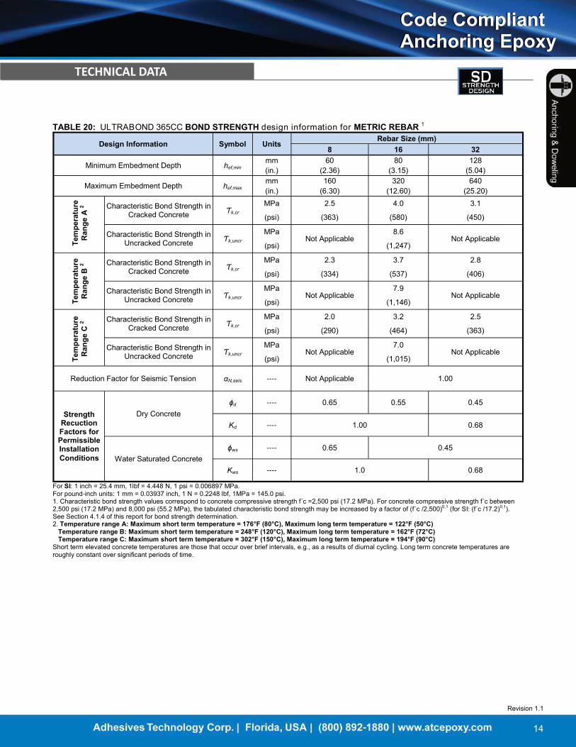
TABLE 20: ULTRABOND 365CC BOND STRENGTH design information for METRIC REBAR 1
Design Information Symbol Units
Rebar Size (mm)
8 16 32
Minimum Embedment Depth hef,min
mm 60 80 128
(in.) (2.36) (3.15) (5.04)
Maximum Embedment Depth hef,max
mm 160 320 640
(in.) (6.30) (12.60) (25.20)
Characteristic Bond Strength in Cracked Concrete
Ƭk,cr
MPa 2.5 4.0 3.1
(psi) (363) (580) (450)
Characteristic Bond Strength in Uncracked Concrete
Ƭk,uncr
MPa
Not Applicable
8.6 Not Applicable
(psi) (1,247)
Characteristic Bond Strength in Cracked Concrete
Ƭk,cr
MPa 2.3 3.7 2.8
(psi) (334) (537) (406)
Characteristic Bond Strength in Uncracked Concrete
Ƭk,uncr
MPa
Not Applicable
7.9 Not Applicable
(psi) (1,146)
Characteristic Bond Strength in Cracked Concrete
Ƭk,cr
MPa 2.0 3.2 2.5
(psi) (290) (464) (363)
Characteristic Bond Strength in Uncracked Concrete
Ƭk,uncr
MPa
Not Applicable
7.0 Not Applicable
(psi) (1,015)
Reduction Factor for Seismic Tension αN,seis ---- Not Applicable 1.00
Strength Recuction Factors for Permissible Installation Conditions
Dry Concrete
ɸd ---- 0.65 0.55 0.45
Kd ---- 1.00 0.68
Water Saturated Concrete
ɸws ---- 0.65 0.45
Kws ---- 1.0 0.68
For SI: 1 inch = 25.4 mm, 1lbf = 4.448 N, 1 psi = 0.006897 MPa. For pound-inch units: 1 mm = 0.03937 inch, 1 N = 0.2248 lbf, 1MPa = 145.0 psi. 1. Characteristic bond strength values correspond to concrete compressive strength f´c =2,500 psi (17.2 MPa). For concrete compressive strength f´c between 2,500 psi (17.2 MPa) and 8,000 psi (55.2 MPa), the tabulated characteristic bond strength may be increased by a factor of (f´c /2,500)0,1 (for SI: (f´c /17.2)0,1). See Section 4.1.4 of this report for bond strength determination. 2. Temperature range A: Maximum short term temperature = 176°F (80°C), Maximum long term temperature = 122°F (50°C) Temperature range B: Maximum short term temperature = 248°F (120°C), Maximum long term temperature = 162°F (72°C) Temperature range C: Maximum short term temperature = 302°F (150°C), Maximum long term temperature = 194°F (90°C) Short term elevated concrete temperatures are those that occur over brief intervals, e.g., as a results of diurnal cycling. Long term concrete temperatures are roughly constant over significant periods of time.
Tem
pera
ture
R
ange
C 2


![Plunger Lift[1]](https://static.fdocuments.net/doc/165x107/55cf8e43550346703b903ec9/plunger-lift1.jpg)