Codal Practices Rcc Design Part b Design by vkmehta
54
PART B :DESIGN ASPECTS PART B :DESIGN ASPECTS CODAL PRACTICES FOR CIVIL CODAL PRACTICES FOR CIVIL ENGINEERS ENGINEERS
-
Upload
vijaymehta345 -
Category
Documents
-
view
2.141 -
download
4
Transcript of Codal Practices Rcc Design Part b Design by vkmehta

PART B :DESIGN ASPECTSPART B :DESIGN ASPECTS
CODAL PRACTICES FOR CIVIL CODAL PRACTICES FOR CIVIL ENGINEERSENGINEERS

DESIGN CRITERIADESIGN CRITERIA
PROJECT SPECIFIC DESIGN BASIS.PROJECT SPECIFIC DESIGN BASIS. LOCAL CONDITION AND SITE SPECIFIC DATALOCAL CONDITION AND SITE SPECIFIC DATA SPECIAL CONSIDERATIONS.SPECIAL CONSIDERATIONS. DESIGN REQUIREMENTSDESIGN REQUIREMENTS
STANDARD GUIDES AND SPECIFICATIONS.STANDARD GUIDES AND SPECIFICATIONS.
CODAL AND GOOD ENGINEERING PRACTICES.CODAL AND GOOD ENGINEERING PRACTICES.

DESIGN CONSIDERATIONDESIGN CONSIDERATION
SAFETY AND SERVICEABILITY SAFETY AND SERVICEABILITY REQUIREMENT REQUIREMENT LIMIT STATE LIMIT STATE DESIGN AS PER IS 456-2000DESIGN AS PER IS 456-2000
STRUCTURES ARE DESIGNED TO STRUCTURES ARE DESIGNED TO WITHSTAND SAFELY ALL LOADS WITHSTAND SAFELY ALL LOADS LIABLE TO ACT ON THE STRUCTURE LIABLE TO ACT ON THE STRUCTURE AND IN ADDITION SATISFY THE AND IN ADDITION SATISFY THE SERVICEABILITY REQUIREMENTS OF SERVICEABILITY REQUIREMENTS OF DEFLECTION AND CRACKING.DEFLECTION AND CRACKING.
DESIGN CONSIDERATIONDESIGN CONSIDERATION
LIMIT STATE OF COLLAPSELIMIT STATE OF COLLAPSE THE STRUCTURE SHALL BE DESIGNED AND THE STRUCTURE SHALL BE DESIGNED AND
CHECKED AT EVERY SECTION FOR ITS CHECKED AT EVERY SECTION FOR ITS RESISTANCE TO BENDING, SHEAR, TORSION RESISTANCE TO BENDING, SHEAR, TORSION AND AXIAL CAPACITY AGAINST ALL THE AND AXIAL CAPACITY AGAINST ALL THE LOAD COMBINATIONS USING APPROPRIATE LOAD COMBINATIONS USING APPROPRIATE PARTIAL SAFETY FACTOR.PARTIAL SAFETY FACTOR.
SEISMIC AND WIND ARE NOT COMBINED.SEISMIC AND WIND ARE NOT COMBINED. LOADS ARE FACTORED USING PARTIAL LOADS ARE FACTORED USING PARTIAL
SAFETY FACTORSSAFETY FACTORS

DESIGN CONSIDERATIONDESIGN CONSIDERATION LIMITLIMIT STATESTATE OF SERVICEABILITYOF SERVICEABILITY THE STRUCTURE ARE CHECKED TO ENSURE THE STRUCTURE ARE CHECKED TO ENSURE
THAT ITS DEFORMATION UNDER WORST THAT ITS DEFORMATION UNDER WORST LOAD COMBINATION ARE COMPATIBLE LOAD COMBINATION ARE COMPATIBLE WITH THE DEGREE OF MOVEMENT WITH THE DEGREE OF MOVEMENT ACCEPTABLE FOR VARIOUS SUPPORTING ACCEPTABLE FOR VARIOUS SUPPORTING COMPONENTS LIKE PIPING JOINTS ,SAFE COMPONENTS LIKE PIPING JOINTS ,SAFE OPERATION OF PLANT AND EQUIPMENT OPERATION OF PLANT AND EQUIPMENT AND FINISHES, GLAZING OF BUILDING ETC. AND FINISHES, GLAZING OF BUILDING ETC.
SPECIFIC CHECK FOR CRACK WIDTH FOR SPECIFIC CHECK FOR CRACK WIDTH FOR LIQUID RETAINING STRUCTURE.LIQUID RETAINING STRUCTURE.

LOADS & LOAD LOADS & LOAD COMBINATIONSCOMBINATIONS
DEAD LOADSDEAD LOADS EQUIPMENT WEIGHTEQUIPMENT WEIGHT
ERECTION/EMPTYERECTION/EMPTY OPERATINGOPERATING HYDROTESTINGHYDROTESTING PUSH/PULL EFFECTSPUSH/PULL EFFECTS DYNAMIC LOADSDYNAMIC LOADS
LIVE /IMPOSED LOADSLIVE /IMPOSED LOADS PIPING LOADS/ANCHOR/FRICTIONPIPING LOADS/ANCHOR/FRICTION ELECTRICAL/INSTRUMENT CABLE TRAYSELECTRICAL/INSTRUMENT CABLE TRAYS
LOADSLOADS & LOAD COMBINATIONS& LOAD COMBINATIONS CRANE GANRTY/MONORAILS LOADS.CRANE GANRTY/MONORAILS LOADS. WIND LOADS(AS PER IS 875 PART 3)WIND LOADS(AS PER IS 875 PART 3)
ON STRUCTURE (using factor k1,k2,k3)ON STRUCTURE (using factor k1,k2,k3) SHIELDING EFFECTSSHIELDING EFFECTS ON EQUIPMENTON EQUIPMENT DYNAMIC ANALYSIS -refer Cl. 7 (Height/width ratio DYNAMIC ANALYSIS -refer Cl. 7 (Height/width ratio
>5)>5) SEISMIC LOADS (IS 1893-Part 1 &4)SEISMIC LOADS (IS 1893-Part 1 &4)
SEISMIC COEFFIENTSEISMIC COEFFIENT RESPONSE SPECTRUM ANALYSISRESPONSE SPECTRUM ANALYSIS IS 1893 SPECTRA IS 1893 SPECTRA SITE SPECIFIC SPECTRUMSITE SPECIFIC SPECTRUM
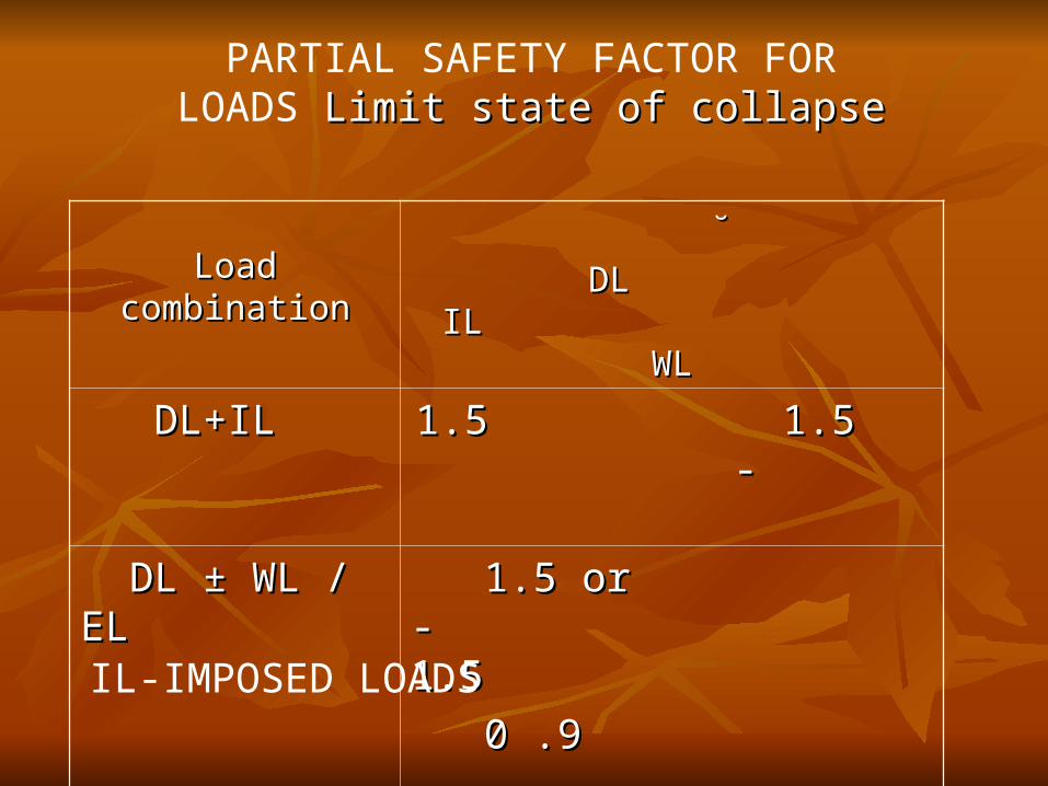
PARTIAL SAFETY FACTOR FOR LOADS Limit state of collapse Limit state of collapse
Load combinationLoad combination ˘̆
DL IL WLDL IL WL
DL+ILDL+IL 1.5 1.5 - 1.5 1.5 -
DL ± WL / ELDL ± WL / EL 1.5 or - 1.5 1.5 or - 1.5
0 .9 0 .9
DL + IL ± WL/ELDL + IL ± WL/EL 1.2 1.2 1.21.2 1.2 1.2
IL-IMPOSED LOADS

Load combinationLoad combination
DL IL WLDL IL WL
DL + ILDL + IL 1.0 1.0 -1.0 1.0 -
DL ± WL/ELDL ± WL/EL 1.0 - 1.01.0 - 1.0
DL+ IL ± WL/ELDL+ IL ± WL/EL 1.0 0.8 0.81.0 0.8 0.8
VALUES OF PARTIAL SAFETY FACTOR ΓF FOR LOADS Limit states of serviceability Limit states of serviceability
LOAD COMBINATIONSLOAD COMBINATIONS WINDWIND
EACH DIRECTION WIND (Unidirectional)EACH DIRECTION WIND (Unidirectional) DIAGONAL WIND FOR SQUARE SHAPES.DIAGONAL WIND FOR SQUARE SHAPES.
SEISMICSEISMIC CALCULATE RESPONSE FROM EACH CALCULATE RESPONSE FROM EACH
DIRECTION .DIRECTION . COMBINED WITH MULTICOMPONENTS AS COMBINED WITH MULTICOMPONENTS AS
PER CLAUSE 6.3.2,ORPER CLAUSE 6.3.2,OR COMBINES AS SRSS (COMBINES AS SRSS (SQUARE ROOT OF THE SUM OF THE SQUARE ROOT OF THE SUM OF THE
SQUARES)SQUARES)
LIMIT STATE OF COLLAPSELIMIT STATE OF COLLAPSE
BEAMSBEAMS
COLUMNCOLUMN
SLABSSLABS

FLEXURAL BEAMS DESIGNFLEXURAL BEAMS DESIGN
*FOR DUCTILE FAILURE STRAIN IN STEEL
ddsingh

BEAM DESIGN TABLEBEAM DESIGN TABLE CALCULATE Mu/bdCALCULATE Mu/bd22
& Select steel grade to & Select steel grade to get ’ p’.get ’ p’.
Table 1 to 4 for singly Table 1 to 4 for singly reinforced beams .reinforced beams . TABLE 4 FOR f ck=30TABLE 4 FOR f ck=30
and f y =415/500 and f y =415/500 etc.→etc.→
Table 45 to 59 for doubly Table 45 to 59 for doubly reinforced beams.reinforced beams.

SHEAR STIRRUP SHEAR STIRRUP
Nominal Shear Stress for beams of uniform depth Nominal Shear Stress for beams of uniform depth
ττv = v = VVUU/ b. d/ b. d
where,where,
VVU U = shear force due to design loads;= shear force due to design loads;
b = breadth of the member, which for flanged b = breadth of the member, which for flanged section shall be taken as the breadth of the web ;section shall be taken as the breadth of the web ;
and and d = effective depth.d = effective depth.
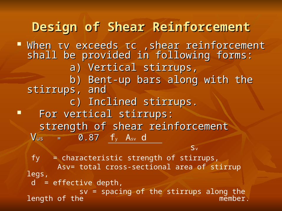
Design of Shear ReinforcementDesign of Shear Reinforcement When When ττvv exceeds exceeds ττcc ,shear reinforcement shall be ,shear reinforcement shall be
provided in following forms:provided in following forms: a) Vertical stirrups,a) Vertical stirrups, b) Bent-up bars along with the stirrups, andb) Bent-up bars along with the stirrups, and c) Inclined stirrups.c) Inclined stirrups.
For vertical stirrups:For vertical stirrups: strength of shear reinforcementstrength of shear reinforcement
VVus = us = 0.87 0.87 fy Asv d
sv
fy = characteristic strength of stirrups, Asv= total cross-sectional area of stirrup legs,
d = effective depth, sv = spacing of the stirrups along the length of the
member.
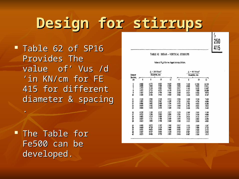
Design for stirrupsDesign for stirrups
Table 62 of SP16 Table 62 of SP16 Provides The value of’ Provides The value of’ Vus /d ‘in KN/cm for Vus /d ‘in KN/cm for FE 415 for different FE 415 for different diameter & spacing .diameter & spacing .
The Table for Fe500 can The Table for Fe500 can be developed.be developed.

TORSIONTORSION
SHEAR AND TORSION(cl.41.3)SHEAR AND TORSION(cl.41.3)
Equivalent Shear , V Equivalent Shear , V ee
V V e =e =VVu u + 1.6 T + 1.6 T u u /b/b
Where,Where,
V V ee = Equivalent Shear, = Equivalent Shear,
VVuu = Shear, = Shear,
T T uu = Torsional Moment, = Torsional Moment,
b = Breadth of beam.b = Breadth of beam.
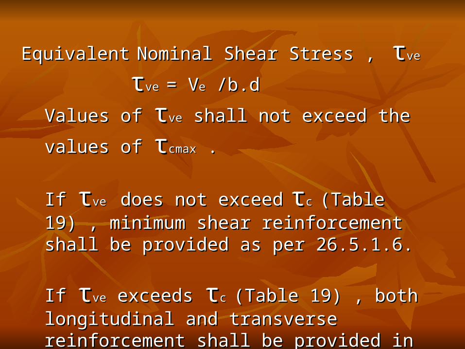
EquivalentEquivalent Nominal Shear Stress ,Nominal Shear Stress , ττveve
ττve ve = V= Vee /b.d /b.d
Values of Values of ττveve shall not exceed the values of shall not exceed the values of ττcmaxcmax . .
If If ττve ve does not exceeddoes not exceed ττc c (Table 19) , minimum shear (Table 19) , minimum shear reinforcement shall be provided as per 26.5.1.6.reinforcement shall be provided as per 26.5.1.6.
If If ττveve exceeds exceeds ττc c (Table 19) , both longitudinal and (Table 19) , both longitudinal and transverse reinforcement shall be provided in transverse reinforcement shall be provided in accordance with 41.4accordance with 41.4

Reinforcement in Members Subjected to Reinforcement in Members Subjected to Torsion(Cl. 41.4)Torsion(Cl. 41.4)
Torsional reinforcement consists of longitudinal and Torsional reinforcement consists of longitudinal and transverse reinforcement.transverse reinforcement.
Longitudinal ReinforcementLongitudinal ReinforcementDesigned to resist an equivalent bending moment ,Designed to resist an equivalent bending moment , MMe1e1 = M = Mu u +M+Mtt
WhereWhereMMu u = = bending moment at the cross-section, &bending moment at the cross-section, &MMt t = = Tu ((1+D/b)/1.7).Tu ((1+D/b)/1.7).Tu = Torsional moment,Tu = Torsional moment,
D = Overall depth& b = Beam breadth.D = Overall depth& b = Beam breadth.

• Transverse ReinforcementTwo legged closed hoops enclosing the
corner longitudinal bars shall have an cross-section Asv,
Asv = Tu Sv + Vu Sv b1 d1 (0.87 fy) 2.5 d1 (0.87 fy)
But total transverse reinforcement shall not be less
than (ττv ev e - - ττCC) b. Sv
0.87 fy
Where,Tu = Torsional moment,Vu = shear force, Sv = spacing of the stirrup reinforcement, b1 = centre-to-centre distance between corner
bars in the direction of the width, d1 = centre-to-centre distance between corner
bars, b = breadth of the member, fy = characteristic strength of the stirrup rebars
ττve ve == equivalent shear stress,
ττcc = shear strength of the concrete (see Table 19).= shear strength of the concrete (see Table 19).

CONTROL OF DEFLECTIONCONTROL OF DEFLECTION
BEAMSBEAMS
Basic values of Span to Basic values of Span to depth up to 10m span:-depth up to 10m span:-
Continuous Beams...26Continuous Beams...26 Simply supported....20Simply supported....20 Cantilever.................7Cantilever.................7
Chart23 of SP16Chart23 of SP16
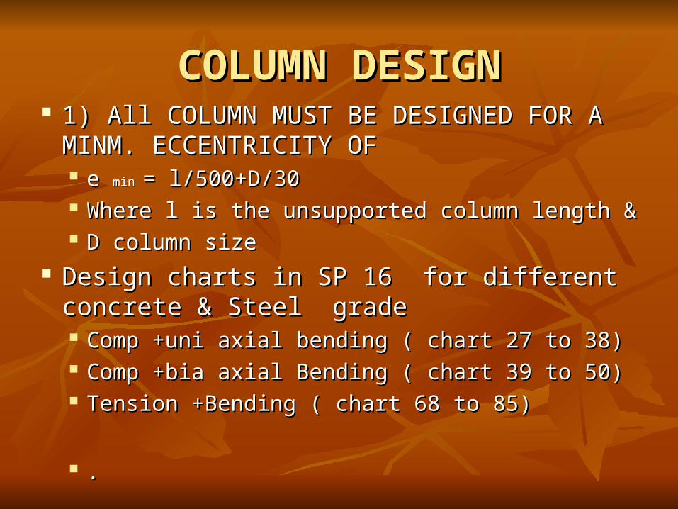
COLUMN DESIGNCOLUMN DESIGN 1) All COLUMN MUST BE DESIGNED FOR A 1) All COLUMN MUST BE DESIGNED FOR A
MINM. ECCENTRICITY OF MINM. ECCENTRICITY OF e e min min = l/500+D/30= l/500+D/30 Where l is the unsupported column length & Where l is the unsupported column length & D column sizeD column size
Design charts in SP 16 for different concrete & Steel Design charts in SP 16 for different concrete & Steel gradegrade Comp +uni axial bending ( chart 27 to 38)Comp +uni axial bending ( chart 27 to 38) Comp +bia axial Bending ( chart 39 to 50)Comp +bia axial Bending ( chart 39 to 50) Tension +Bending ( chart 68 to 85)Tension +Bending ( chart 68 to 85)
..

COLUMN DESIGN COLUMN DESIGN -COMPRESSION-COMPRESSION
1) Short Axially Loaded Members in Compression Pu = 0.4 fck .AC + 0.67 f y .A sc
Where,
Pu = axial load on the member, fck = characteristic compressive strength of the concrete, AC = Area of concrete, f y = characteristic strength of the compression reinforcement, and A sc = area of longitudinal reinforcement for columns.
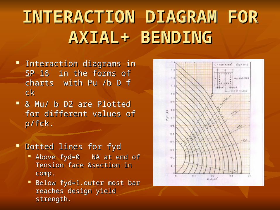
INTERACTION DIAGRAM INTERACTION DIAGRAM FOR AXIAL+ BENDINGFOR AXIAL+ BENDING
Interaction diagrams in SP 16 Interaction diagrams in SP 16 in the forms of charts with Pu in the forms of charts with Pu /b D f ck/b D f ck
& Mu/ b D2 are Plotted for & Mu/ b D2 are Plotted for different values of p/fck.different values of p/fck.
Dotted lines for fydDotted lines for fyd Above fyd=0 NA at end of Above fyd=0 NA at end of
Tension face §ion in comp.Tension face §ion in comp. Below fyd=1.outer most bar Below fyd=1.outer most bar
reaches design yield strength.reaches design yield strength.

Members Subjected to Combined Members Subjected to Combined Axial Load and Biaxial BendingAxial Load and Biaxial Bending
[M[Mux ux /M/Mux1ux1]^]^αα + [M + [Muy uy /M/Muy1uy1]^]^αα ≤ ≤ 1.01.0 where,where,
MMux, ux, MMuy = uy = moments about x and y axes moments about x and y axes due to design loads,due to design loads,
MMux1ux1, , MMuy1 = uy1 = maximum uniaxial moment capacity for maximum uniaxial moment capacity for an axial load of an axial load of Pu, bendingPu, bending about x about x
and y axes respectively, and and y axes respectively, and αα is related to is related to PPuu / / PPuuz.z.
where, where, PPuuz = z = 0.45 f0.45 fck ck .A.AC C + 0.75 f+ 0.75 fyy .A .Ascsc

RELATION BETWEENRELATION BETWEEN PPuu / / PPuuz z ANDAND αα (Refer Chart 64 IN SP16)(Refer Chart 64 IN SP16)
PPuu / / PPuuz`z` αα
< 0.2< 0.2 1.01.0
0.2 to 0.8 0.2 to 0.8 1.0 to 2.01.0 to 2.0
(linear variation)(linear variation)
>0.8>0.8 2.02.0
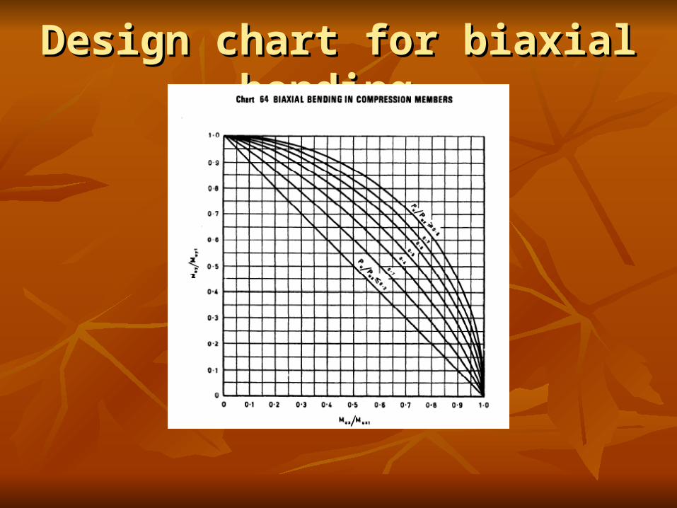
Design chart for biaxial bending Design chart for biaxial bending

ADDITIONAL MOMENTS due to ADDITIONAL MOMENTS due to SlendernessSlenderness
Additional moment shall be taken into accountAdditional moment shall be taken into account.. MMaxax = = Pu D{l Pu D{l exex/D}^2/D}^2 20002000 MMay ay = = Pu b{l Pu b{l eyey/b}^2/b}^2
20002000Where, Where,
l l exex = effective length in respect of major axis, = effective length in respect of major axis, l l eyey = effective length in respect of minor axis, = effective length in respect of minor axis,
D = depth of the cross-section at right angles to the D = depth of the cross-section at right angles to the major major axis, and axis, and
b = width of the member.b = width of the member.NOTE :- Column are slender when L/d>12.NOTE :- Column are slender when L/d>12.
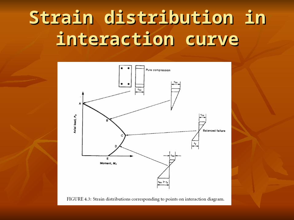
Strain distribution in interaction Strain distribution in interaction curvecurve
SLAB DESIGNSLAB DESIGN SLAB IS DESIGN AS ONE WAY OR TWO SLAB IS DESIGN AS ONE WAY OR TWO
WAY SPAN DEPENDING UPON THE WAY SPAN DEPENDING UPON THE RATIO OF THE TWO SIDES.RATIO OF THE TWO SIDES.
TABLE 26 OF ANNEX .D PROVIDES B.M. TABLE 26 OF ANNEX .D PROVIDES B.M. COEFFICIENT FOR SLAB DESIGN.COEFFICIENT FOR SLAB DESIGN.
SPAN TO DEPTH RATIO FOR SPAN TO DEPTH RATIO FOR DEFLECTION CHECK:DEFLECTION CHECK: S.S SLAB =0.8*35=28S.S SLAB =0.8*35=28 CONTINOUS SLAB=0.8*40=32CONTINOUS SLAB=0.8*40=32
(Factor of 0.8 for FE 415/500 )(Factor of 0.8 for FE 415/500 )
SLAB DESIGN SLAB DESIGN
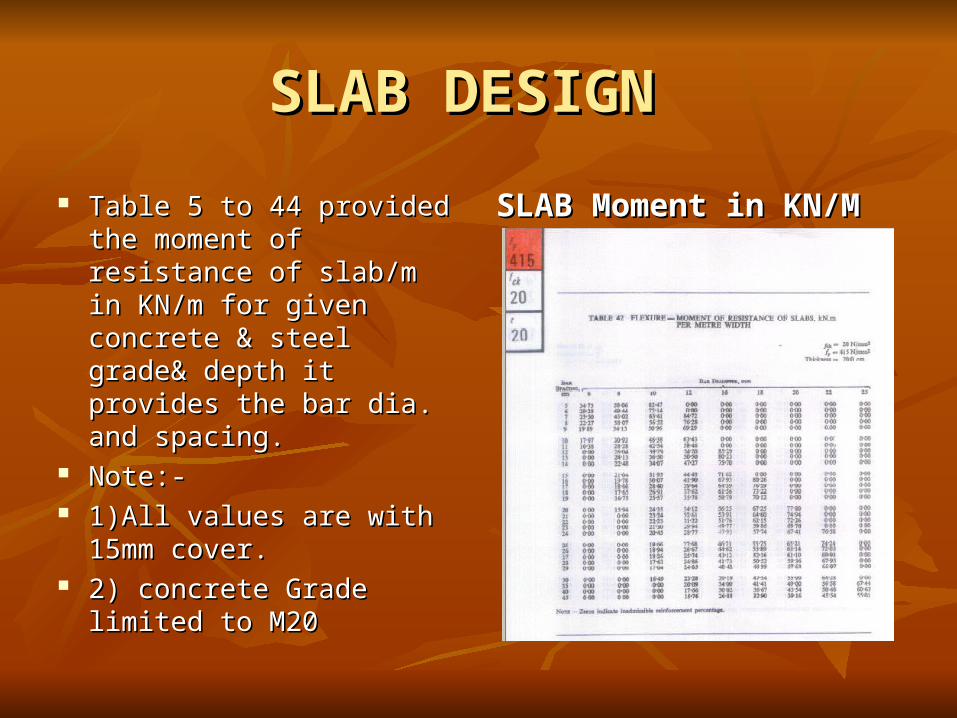
Table 5 to 44 provided the Table 5 to 44 provided the moment of resistance of moment of resistance of slab/m in KN/m for given slab/m in KN/m for given concrete & steel grade& concrete & steel grade& depth it provides the bar dia. depth it provides the bar dia. and spacing.and spacing.
Note:-Note:- 1)All values are with 15mm 1)All values are with 15mm
cover. cover. 2) concrete Grade limited to 2) concrete Grade limited to
M20M20
SLAB Moment in KN/MSLAB Moment in KN/M
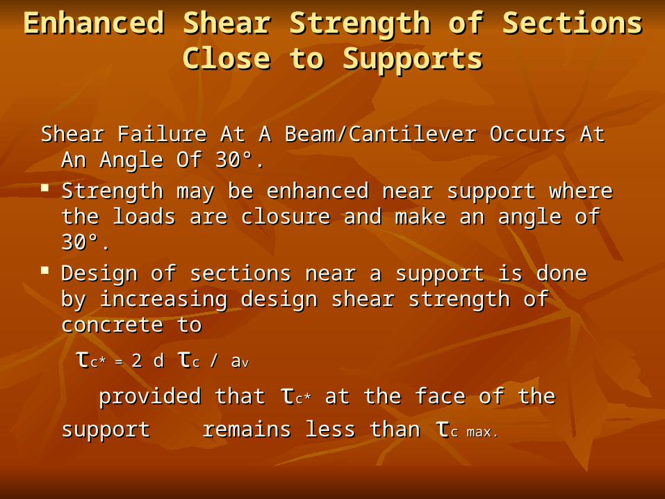
Enhanced Shear Strength of Sections Close to Enhanced Shear Strength of Sections Close to SupportsSupports
Shear Failure At A Beam/Cantilever Occurs At An Shear Failure At A Beam/Cantilever Occurs At An Angle Of 30°.Angle Of 30°.
Strength may be enhanced near support where the Strength may be enhanced near support where the loads are closure and make an angle of 30°.loads are closure and make an angle of 30°.
Design of sections near a support is done by Design of sections near a support is done by increasing design shear strength of concrete toincreasing design shear strength of concrete to
ττc* = c* = 2 d 2 d ττc c / a/ avv
provided that provided that ττc*c* at the face of the support remains at the face of the support remains
less than less than ττc max.c max.
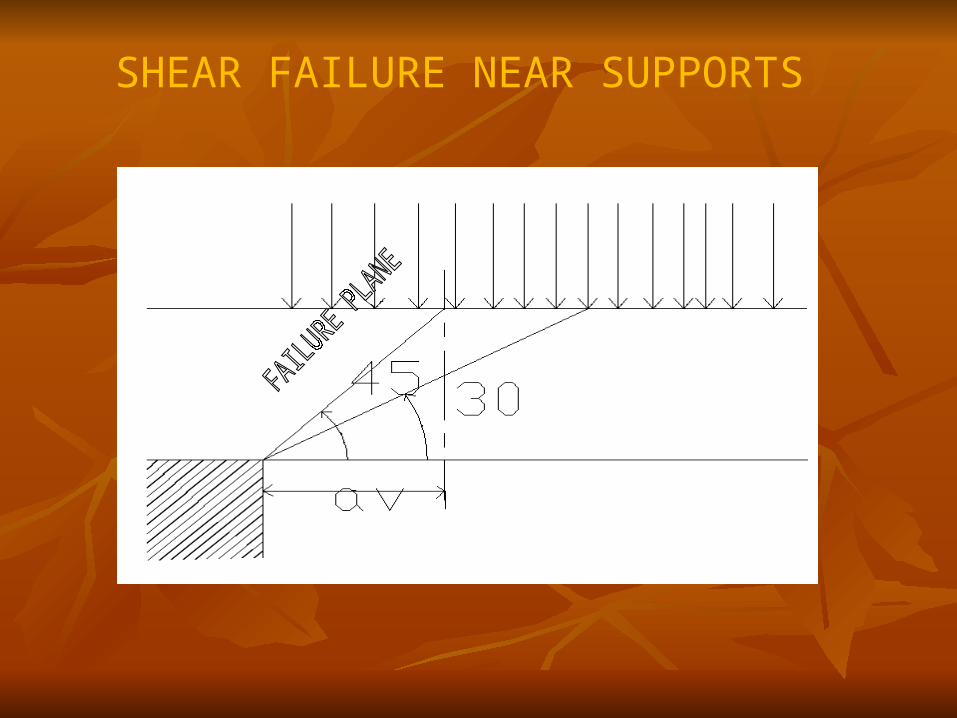
SHEAR FAILURE NEAR SUPPORTS

SECTION FOR ENHENCED SHEAR

DESIGN AIDSDESIGN AIDS ESTIMATE PRELIMANARY SIZES MANUALLY/ ESTIMATE PRELIMANARY SIZES MANUALLY/
PAST JOB EXPERIENCESPAST JOB EXPERIENCES ALL ANALYSIS ARE PERFORMED USING STAADALL ANALYSIS ARE PERFORMED USING STAAD INHOUSE CALCULATION SHEETS AND DESIGN INHOUSE CALCULATION SHEETS AND DESIGN
AIDS IN LOTUS/EXCEL AVAILABLE FOR AIDS IN LOTUS/EXCEL AVAILABLE FOR DESIGN OF COLUMN/BEAMS SLABS & DESIGN OF COLUMN/BEAMS SLABS & FOOTING.FOOTING.
INVARIABLY TRY TO MAINTAIN INVARIABLY TRY TO MAINTAIN SYSTEMATICALLY ,DESIGN FILES & BACK UP SYSTEMATICALLY ,DESIGN FILES & BACK UP OF ALL DESIGN CALCULATIONS.OF ALL DESIGN CALCULATIONS.

ATTACHMENTS

ISIS 875:-DESIGN LOADS FOR BLDGS.& 875:-DESIGN LOADS FOR BLDGS.& STR.STR.
(OTHER THAN SEISMIC)(OTHER THAN SEISMIC) PART 1 DEAD LOADSPART 1 DEAD LOADS PART 2 IMPOSED LOADSPART 2 IMPOSED LOADS PART 3 WIND LOADSPART 3 WIND LOADS PART 4 SNOW LOADSPART 4 SNOW LOADS PART 5 SPECIAL LOADS & LOAD COMBINATIONS.PART 5 SPECIAL LOADS & LOAD COMBINATIONS.
TEMPERATURE EFFECTSTEMPERATURE EFFECTS HYDROSTATIC & SOIL PRESSURE.HYDROSTATIC & SOIL PRESSURE. STRUCTURE SAFETY DURING CONSTRCUTIONSTRUCTURE SAFETY DURING CONSTRCUTION ACCIDENTAL LOADS.ACCIDENTAL LOADS.
LOAD COMBINATIONSLOAD COMBINATIONS
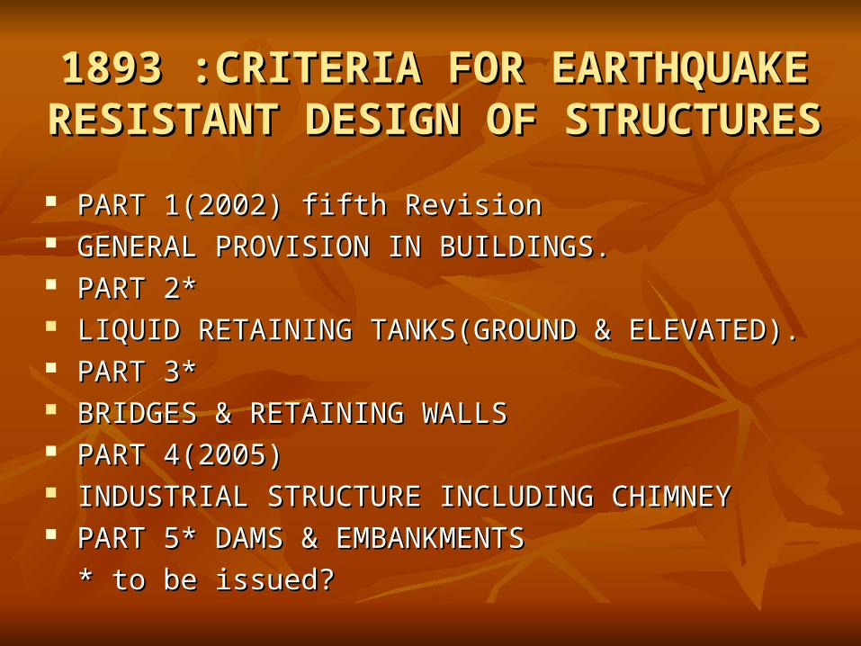
1893 :CRITERIA FOR EARTHQUAKE 1893 :CRITERIA FOR EARTHQUAKE RESISTANT DESIGN OF STRUCTURESRESISTANT DESIGN OF STRUCTURES
PART 1(2002) fifth RevisionPART 1(2002) fifth Revision GENERAL PROVISION IN BUILDINGS.GENERAL PROVISION IN BUILDINGS. PART 2*PART 2* LIQUID RETAINING TANKS(GROUND & ELEVATED).LIQUID RETAINING TANKS(GROUND & ELEVATED). PART 3*PART 3* BRIDGES & RETAINING WALLSBRIDGES & RETAINING WALLS PART 4(2005)PART 4(2005) INDUSTRIAL STRUCTURE INCLUDING CHIMNEYINDUSTRIAL STRUCTURE INCLUDING CHIMNEY PART 5* DAMS & EMBANKMENTSPART 5* DAMS & EMBANKMENTS
* to be issued?* to be issued?

STRESS STRAIN DIAGRAM FOR STRESS STRAIN DIAGRAM FOR DIFERRENT STEEL GRADESDIFERRENT STEEL GRADES
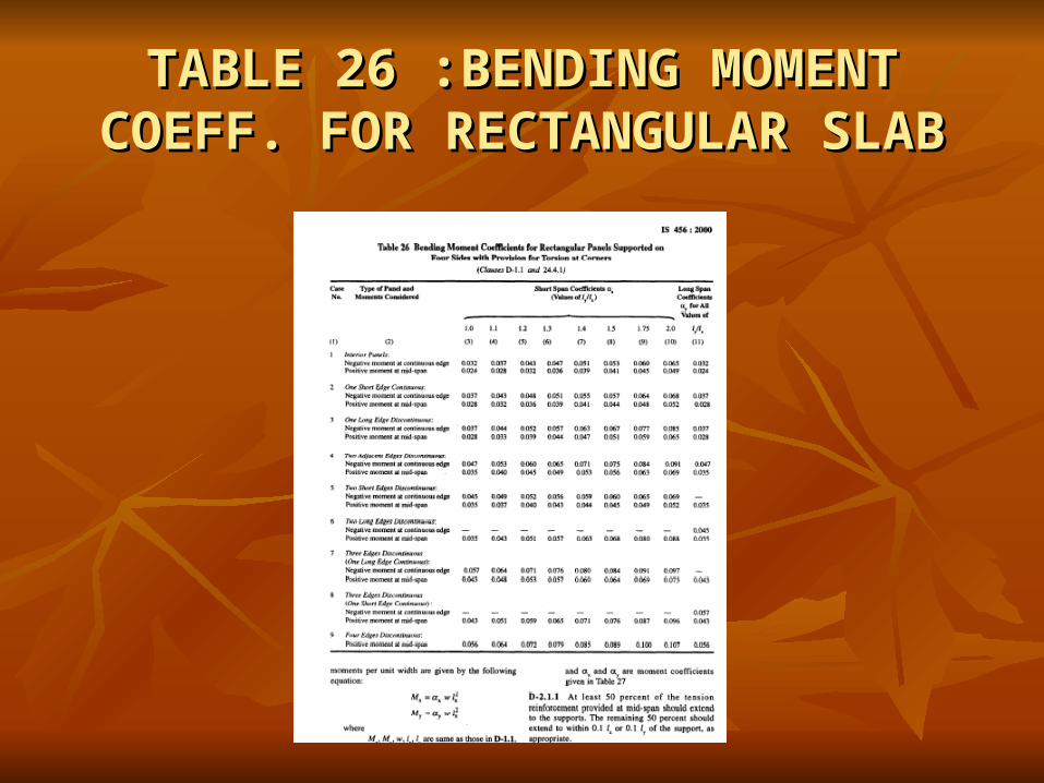
TABLE 26 :BENDING MOMENT TABLE 26 :BENDING MOMENT COEFF. FOR RECTANGULAR SLABCOEFF. FOR RECTANGULAR SLAB

SHEAR STRESS SHEAR STRESS ττc IN N/mmc IN N/mm22
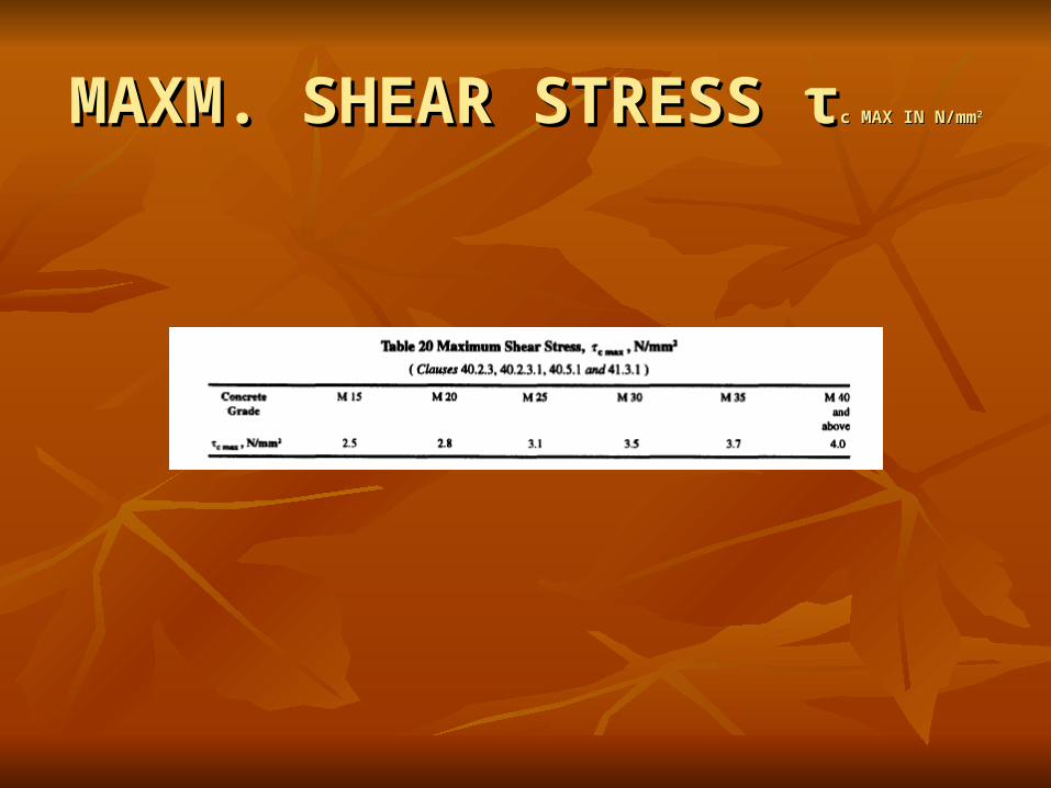
MAXM. SHEAR STRESS MAXM. SHEAR STRESS ττc MAX IN N/mmc MAX IN N/mm22
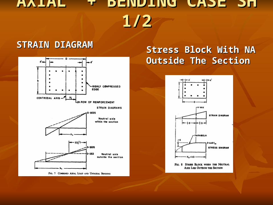
AXIAL + BENDING CASE SH AXIAL + BENDING CASE SH 1/21/2
STRAIN DIAGRAMSTRAIN DIAGRAMStress Block With NA Stress Block With NA Outside The SectionOutside The Section

FORMULA FOR DESIGN FORMULA FOR DESIGN CHARTS SH 2/2CHARTS SH 2/2

IMPOSED LOADS AS PER IMPOSED LOADS AS PER IS875-PART 2IS875-PART 2

IMPOSED LOADS AS PER EIL IMPOSED LOADS AS PER EIL DESIGN BASISDESIGN BASIS
Process Building/Technological Structure Process Building/Technological Structure (Open/Enclosed type)(Open/Enclosed type)
Operating areaOperating area -- 5.0 kN/m5.0 kN/m22
Maintenance areaMaintenance area -- 7.5 kN/m7.5 kN/m22
Compressor House/TG houseCompressor House/TG house Operating areaOperating area -- 7.5 kN/m7.5 kN/m22
Maintenance areaMaintenance area -- 7.5 kN/m7.5 kN/m22
Substation/Control RoomSubstation/Control Room Panel floorPanel floor -- 10.0 kN/m10.0 kN/m22
* * FOR OTHER AREA REFER DESIGN BASIS FOR OTHER AREA REFER DESIGN BASIS

FIGURE 1 OF IS875 PART 3FIGURE 1 OF IS875 PART 3
SPEED VARIES FROM 33 TO 55M/S

SEISMIC ZONE OF INDIASEISMIC ZONE OF INDIA

Sa/g vs TIME PERIODSa/g vs TIME PERIOD

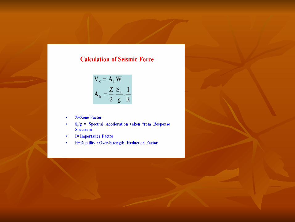
HORIZONTAL SEISMIC HORIZONTAL SEISMIC COEFF.COEFF.
DESIGN HORIZONTAL DESIGN HORIZONTAL SEISMIC COEFF.SEISMIC COEFF.
ZONE FACTORZONE FACTOR

EARTHQUAKE RESPONSEEARTHQUAKE RESPONSE

!!!!!!!!
THANK YOU!THANK YOU!