COAXIAL, TRIAXIAL, MULTI & MIXED CONNECTORS · of similar connectors («G» key standard). Fixed...
36
COAXIAL, TRIAXIAL, MULTI & MIXED CONNECTORS SHORT FORM CATALOGUE
Transcript of COAXIAL, TRIAXIAL, MULTI & MIXED CONNECTORS · of similar connectors («G» key standard). Fixed...
COAXIAL, TRIAXIAL, MULTI & MIXED CONNECTORS
SHORT FORM CATALOGUE
www.lemo.com
® ®
Precision modular connectors to suit your applicationSince its creation in Switzerland in 1946 the LEMO Group has been recognized as a global leader of circular Push-Pull con-nectors and connector solutions. Today LEMO and its affiliated companies, REDEL and COELVER, are active in more than80 countries with the help of over 40 subsidiaries and distributors.
Over 50ʼ000 connectorsThe modular design of the LEMO range provides over 50’000 connectors from miniature ø 3 mm to ø 50 mm, capable of han-dling cable diameters up to 30 mm and for up to 114 contacts.
This vast portfolio enables you to select the ideal connector configuration to suit almost any specific requirement in most mar-kets, including medical devices, test and measurement instruments, machinery, audio video broadcast, telecommunicationsand military.
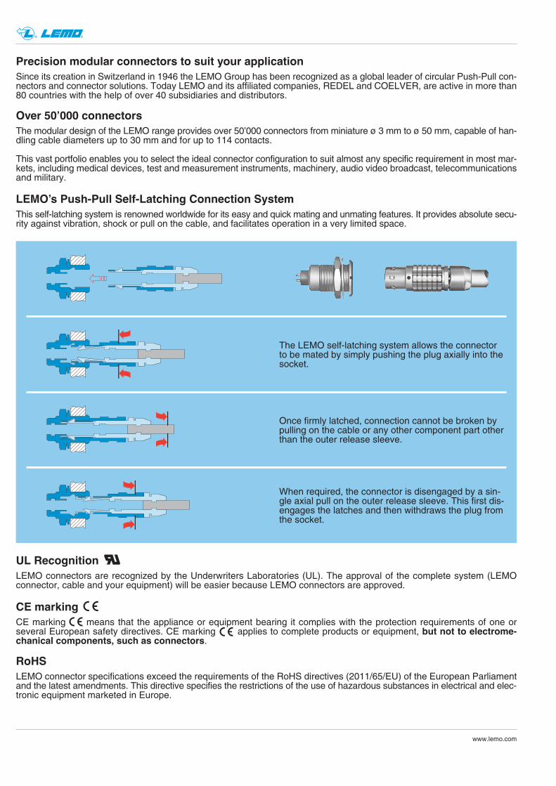
LEMOʼs Push-Pull Self-Latching Connection System
The LEMO self-latching system allows the connectorto be mated by simply pushing the plug axially into thesocket.
This self-latching system is renowned worldwide for its easy and quick mating and unmating features. It provides absolute secu-rity against vibration, shock or pull on the cable, and facilitates operation in a very limited space.
UL RecognitionLEMO connectors are recognized by the Underwriters Laboratories (UL). The approval of the complete system (LEMOconnector, cable and your equipment) will be easier because LEMO connectors are approved.
CE markingCE marking means that the appliance or equipment bearing it complies with the protection requirements of one orseveral European safety directives. CE marking applies to complete products or equipment, but not to electrome-chanical components, such as connectors.
RoHSLEMO connector specifications exceed the requirements of the RoHS directives (2011/65/EU) of the European Parliamentand the latest amendments. This directive specifies the restrictions of the use of hazardous substances in electrical and elec-tronic equipment marketed in Europe.
Once firmly latched, connection cannot be broken bypulling on the cable or any other component part otherthan the outer release sleeve.
When required, the connector is disengaged by a sin-gle axial pull on the outer release sleeve. This first dis-engages the latches and then withdraws the plug fromthe socket.
1www.lemo.com
® ®
Introduction
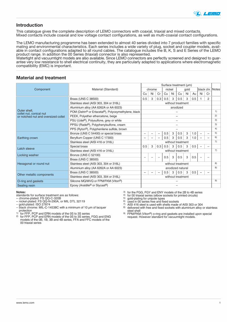
Material and treatment
This catalogue gives the complete description of LEMO connectors with coaxial, triaxial and mixed contacts. Mixed contacts include coaxial and low voltage contact configurations, as well as multi-coaxial contact configurations.
The LEMO manufacturing programme has been extended to almost 40 series divided into 7 product families with specificmating and environmental characteristics. Each series includes a wide variety of plug, socket and coupler models, avail-able in contact configurations adapted to all round cables. The catalogue includes the B, K, S and E Series of the LEMOproduct range. In addition the 00 Series (triaxial) connector is also represented. Watertight and vacuumtight models are also available. Since LEMO connectors are perfectly screened and designed to guar-antee very low resistance to shell electrical continuity, they are particularly adapted to applications where electromagneticcompatibility (EMC) is important.
Component
Outer shell, collet nut, conical nutor notched nut and oversized collet
Earthing crown
Latch sleeve
Locking washer
Hexagonal or round nut
Other metallic components
O-ring and gasketsSealing resin
Material (Standard)
Brass (UNS C 38500)Stainless steel (AISI 303, 304 or 316L)Aluminium alloy (AA 6262A or AA 6023)POM (Delrin® or Ertacetal®), Polyoxymethylene, blackPEEK, Polyether ethercetone, beigePSU (Udel®), Polysulfone, grey or whitePPSU (Radel®), Polyphenylsulfone, creamPPS (Ryton®), Polyphenilene sulfide, brownBronze (UNS C 54400) or special brassBeryllium Copper (UNS C 17300)Stainless steel (AISI 416 or 316L)Special brassStainless steel (AISI 416 or 316L)Bronze (UNS C 52100)Brass (UNS C 38500)Stainless steel (AISI 303, 304 or 316L)Aluminium alloy (AA 6262A or AA 6023)Brass (UNS C 38500)Stainless steel (AISI 303, 304 or 316L)Silicone MQ/MVQ or FPM/FKM (Viton®)Epoxy (Araldite® or Stycast®)
0.5 3 0.3 0.5 3 0.5 3 0.5 1 2without treatment
anodized– 1)
– 2)
– 3)
– 3)
– 4)
– – – 0.5 3 0.5 3 1.0 – – 5)
– – – 0.5 3 0.5 3 1.0 – – 6)
without treatment 7)
0.5 3 0.3 0.5 3 0.5 3 0.5 – –without treatment 7)
– – – 0.5 3 0.5 3 0.5 – –
without treatment 8)
anodized natural 8)
– – – 0.5 3 0.5 3 0.5 – –without treatment
– 9)
–
Surface treatment (µm)chrome nickel gold black chr.
Cu Ni Cr Cu Ni Cu Ni Au Ni Cr
Notes:
standards for surface treatment are as follows:– chrome-plated: FS QQ-C-320B– nickel-plated: FS QQ-N-290A, or MIL DTL 32119– gold-plated: ISO 27874– black chrome: MIL-C-14538C with a minimum of 10 µm of lacquer protection
1) for FFP, PCP and ERN models of the 0S to 3S series2) for FFP, PCP and ERN models of the 0S to 3S series, FGG and ENGmodels of the 0B, 1B, 3B and 4B series, FFA and FFC models of the00 triaxial series
3) for the FGG, FGY and ENY models of the 2B to 4B series4) for 00 triaxial series (elbow sockets for printed circuits)5) gold-plating for unipole types6) used in 00 series free and fixed sockets7) AISI 416 steel is used with shells made of AISI 303 or 3048) delivered with free and fixed sockets with aluminium alloy or stainlesssteel shell
9) FPM/FKM (Viton®) o-ring and gaskets are installed upon specialrequest. However standard for vacuumtight models.
Notes
FHG
FIG
FKG
FGG
FFG
FGG
FEG
FNG
FDG
EJG PHG
PHG
PNG
FGGFGG
FGYFGY
ENG
ENY
FAG
FWG EGG
EHG
EKG
ENG EEG
ECG
PEG
PKG
PFG
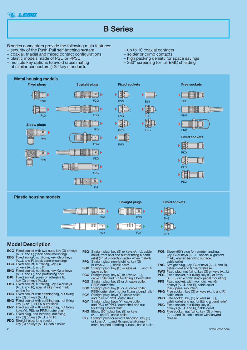
B Series
B series connectors provide the following main features:– security of the Push-Pull self-latching system – up to 10 coaxial contacts– coaxial, triaxial and mixed contact configurations – solder or crimp contacts– plastic models made of PSU or PPSU – high packing density for space savings– multiple key options to avoid cross mating – 360° screening for full EMC shieldingof similar connectors («G» key standard).
Fixed plugs Straight plugs Fixed sockets Free sockets
Elbow plugs
Fixed sockets
Fixed socketsStraight plugsPlastic housing models
Metal housing models
2 www.lemo.com
® ®
Model DescriptionECG Fixed socket with two nuts, key (G) or keys
(A…L and R) (back panel mounting)EEG Fixed socket, nut fixing, key (G) or keys
(A…L and R) (back panel mounting)EGG Fixed socket, nut fixing, key (G)
or keys (A…L and R)EHG Fixed socket, nut fixing, key (G) or keys
(A…L and R), and protruding shellEJG Fixed socket, press or adhesive fit,
key (G) or keys (A…L)EKG Fixed socket, nut fixing, key (G) or keys
(A…L and R), special alignment mark on the front
ENG Fixed socket with earthing tag, nut fixing, key (G) or keys (A…L)
ENG Fixed socket with earthing tag, nut fixing, key (G or J), PEEK outer shell
ENY Fixed socket with earthing tag, nut fixing,keys (Y), PSU or PPSU outer shell
FAG Fixed plug, non-latching, nut fixing, key (G) or keys (A…L and R)
FDG Straight plug, long version, key (G) or keys (A…L), cable collet
FEG Straight plug, key (G) or keys (A…L), cablecollet, front seal and nut for fitting a bendrelief (IP 54 protection index when mated)
FFG Straight plug, non-latching, key (G) or keys (A…L), cable collet
FGG Straight plug, key (G) or keys (A…L and R), cable collet
FGG Straight plug, key (G) or keys (A…L), cable collet and nut for fitting a bend relief
FGG Straight plug, key (G or J), cable collet, PEEK outer shell
FGG Straight plug, key (G or J), cable collet, PEEK outer shell, nut for fitting a bend relief
FGY Straight plug, keys (Y), cable collet and PSU or PPSU outer shell
FGY Straight plug, keys (Y), cable collet and PSU or PPSU outer shell and nut for fitting a bend relief
FHG Elbow (90°) plug, key (G) or keys (A…L and R), cable collet
FIG Straight plug for remote handling, key (G) or keys (A…L and R), special alignmentmark, knurled handling surface, cable collet
FKG Elbow (90°) plug for remote handling, key (G) or keys (A…L), special alignmentmark, knurled handling surface, cable collet
FNG Straight plug, key (G) or keys (A…L and R),cable collet and lanyard release
FWG Fixed plug, nut fixing, key (G) or keys (A…L)PEG Fixed socket, nut fixing, key (G) or keys
(A…L), cable collet (back panel mounting)PFG Fixed socket, with two nuts, key (G)
or keys (A…L and R), cable collet (back panel mounting)
PHG Free socket, key (G) or keys (A…L and R),cable collet
PHG Free socket, key (G) or keys (A…L), cable collet and nut for fitting a bend relief
PKG Fixed socket, nut fixing, key (G) or keys (A…L and R), cable collet
PNG Free socket, nut fixing, key (G) or keys (A…L and R), cable collet with lanyardrelease
1
1
3www.lemo.com
® ®
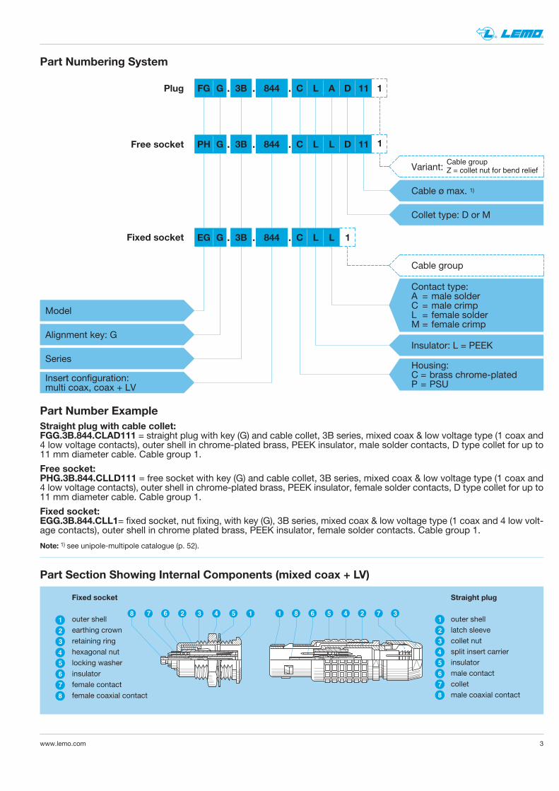
Straight plug with cable collet:FGG.3B.844.CLAD111 = straight plug with key (G) and cable collet, 3B series, mixed coax & low voltage type (1 coax and4 low voltage contacts), outer shell in chrome-plated brass, PEEK insulator, male solder contacts, D type collet for up to11 mm diameter cable. Cable group 1.
FG G 3B
Insert configuration:multi coax, coax + LV
Cable ø max. 1)
Collet type: D or M
844
Series
Model
Alignment key: G
C L A D 11
Fixed socket EG G 3B 844 C L L
Housing:C = brass chrome-platedP = PSU
Insulator: L = PEEK
Contact type:A = male solderC = male crimpL = female solderM = female crimp
Fixed socket:EGG.3B.844.CLL1= fixed socket, nut fixing, with key (G), 3B series, mixed coax & low voltage type (1 coax and 4 low volt-age contacts), outer shell in chrome plated brass, PEEK insulator, female solder contacts. Cable group 1.
Cable group
Part Numbering System
Plug
PH G 3B 844 C L L D 11Free socket
Part Section Showing Internal Components (mixed coax + LV)
13 4 5267
4
3
6
7
8
5
1
2
4
3
6
5
7
8
1
2
8 6 5 4 2 7 38 1
Fixed socket
outer shellearthing crownretaining ringhexagonal nutlocking washerinsulatorfemale contactfemale coaxial contact
Straight plug
outer shelllatch sleevecollet nutsplit insert carrierinsulatormale contactcolletmale coaxial contact
Part Number Example
Free socket:PHG.3B.844.CLLD111 = free socket with key (G) and cable collet, 3B series, mixed coax & low voltage type (1 coax and4 low voltage contacts), outer shell in chrome-plated brass, PEEK insulator, female solder contacts, D type collet for up to11 mm diameter cable. Cable group 1.
. . .
. . .
. . . 1
Note: 1) see unipole-multipole catalogue (p. 52).
Cable groupZ = collet nut for bend reliefVariant:
4 www.lemo.com
® ®
K Series
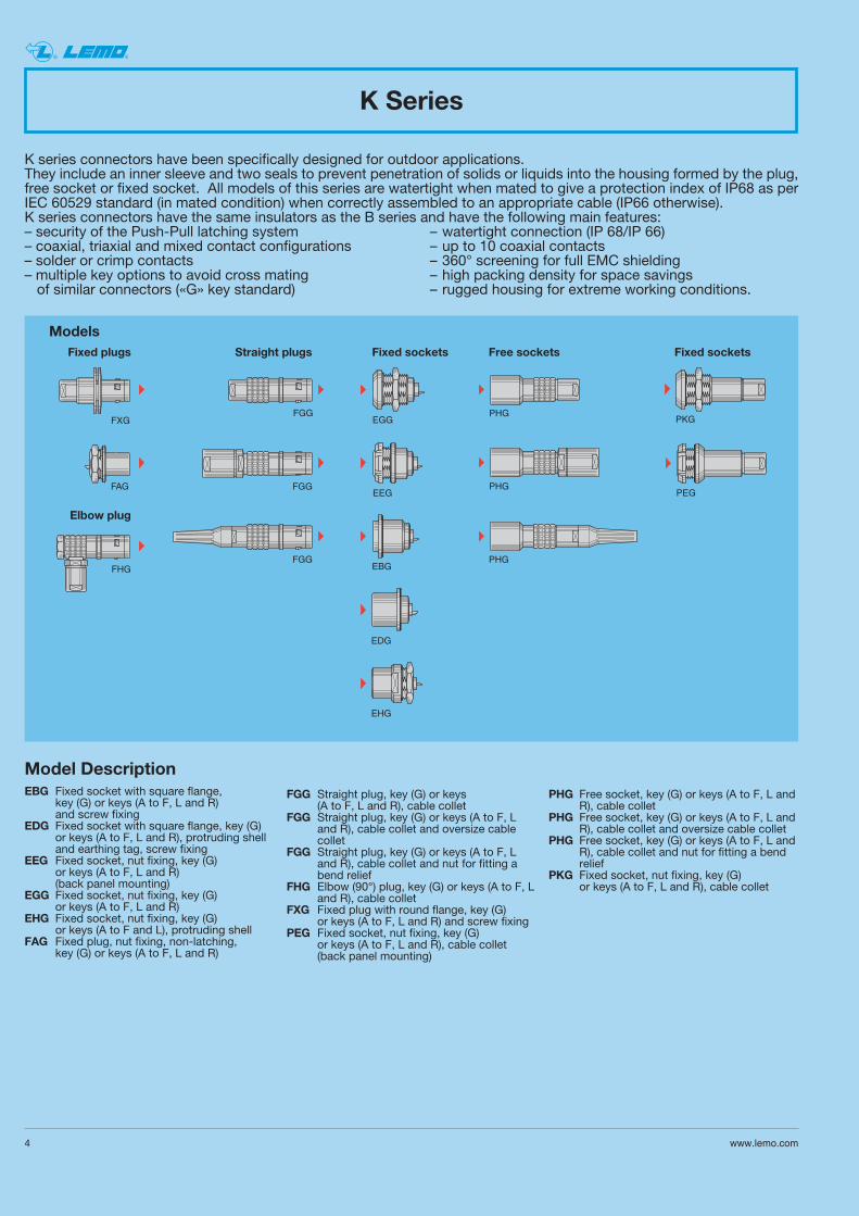
K series connectors have been specifically designed for outdoor applications.They include an inner sleeve and two seals to prevent penetration of solids or liquids into the housing formed by the plug,free socket or fixed socket. All models of this series are watertight when mated to give a protection index of IP68 as perIEC 60529 standard (in mated condition) when correctly assembled to an appropriate cable (IP66 otherwise).K series connectors have the same insulators as the B series and have the following main features:– security of the Push-Pull latching system – watertight connection (IP 68/IP 66)– coaxial, triaxial and mixed contact configurations – up to 10 coaxial contacts – solder or crimp contacts – 360° screening for full EMC shielding– multiple key options to avoid cross mating – high packing density for space savingsof similar connectors («G» key standard) – rugged housing for extreme working conditions.
FGG
FGG
FGG
EGG
PHG
EDG
EBG
EHG
FXG
FAG
FHG
PHG
PHG
PKG
PEGEEG
Straight plugs Fixed sockets Free sockets Fixed socketsFixed plugs
Elbow plug
Models
Model DescriptionEBG Fixed socket with square flange,
key (G) or keys (A to F, L and R) and screw fixing
EDG Fixed socket with square flange, key (G) or keys (A to F, L and R), protruding shell and earthing tag, screw fixing
EEG Fixed socket, nut fixing, key (G) or keys (A to F, L and R) (back panel mounting)
EGG Fixed socket, nut fixing, key (G) or keys (A to F, L and R)
EHG Fixed socket, nut fixing, key (G) or keys (A to F and L), protruding shell
FAG Fixed plug, nut fixing, non-latching, key (G) or keys (A to F, L and R)
FGG Straight plug, key (G) or keys (A to F, L and R), cable collet
FGG Straight plug, key (G) or keys (A to F, Land R), cable collet and oversize cablecollet
FGG Straight plug, key (G) or keys (A to F, Land R), cable collet and nut for fitting abend relief
FHG Elbow (90°) plug, key (G) or keys (A to F, Land R), cable collet
FXG Fixed plug with round flange, key (G) or keys (A to F, L and R) and screw fixing
PEG Fixed socket, nut fixing, key (G) or keys (A to F, L and R), cable collet (back panel mounting)
PHG Free socket, key (G) or keys (A to F, L andR), cable collet
PHG Free socket, key (G) or keys (A to F, L andR), cable collet and oversize cable collet
PHG Free socket, key (G) or keys (A to F, L andR), cable collet and nut for fitting a bendrelief
PKG Fixed socket, nut fixing, key (G) or keys (A to F, L and R), cable collet
5www.lemo.com
® ®
Part Section Showing Internal Components (mixed coax + LV)
4
3
1
2
5
6
7
8
14 7325 6 3 7 6 4 1 9 11 128 2
4
3
1
2
5
6
7
8
9
10
11
12
13
10 58 13
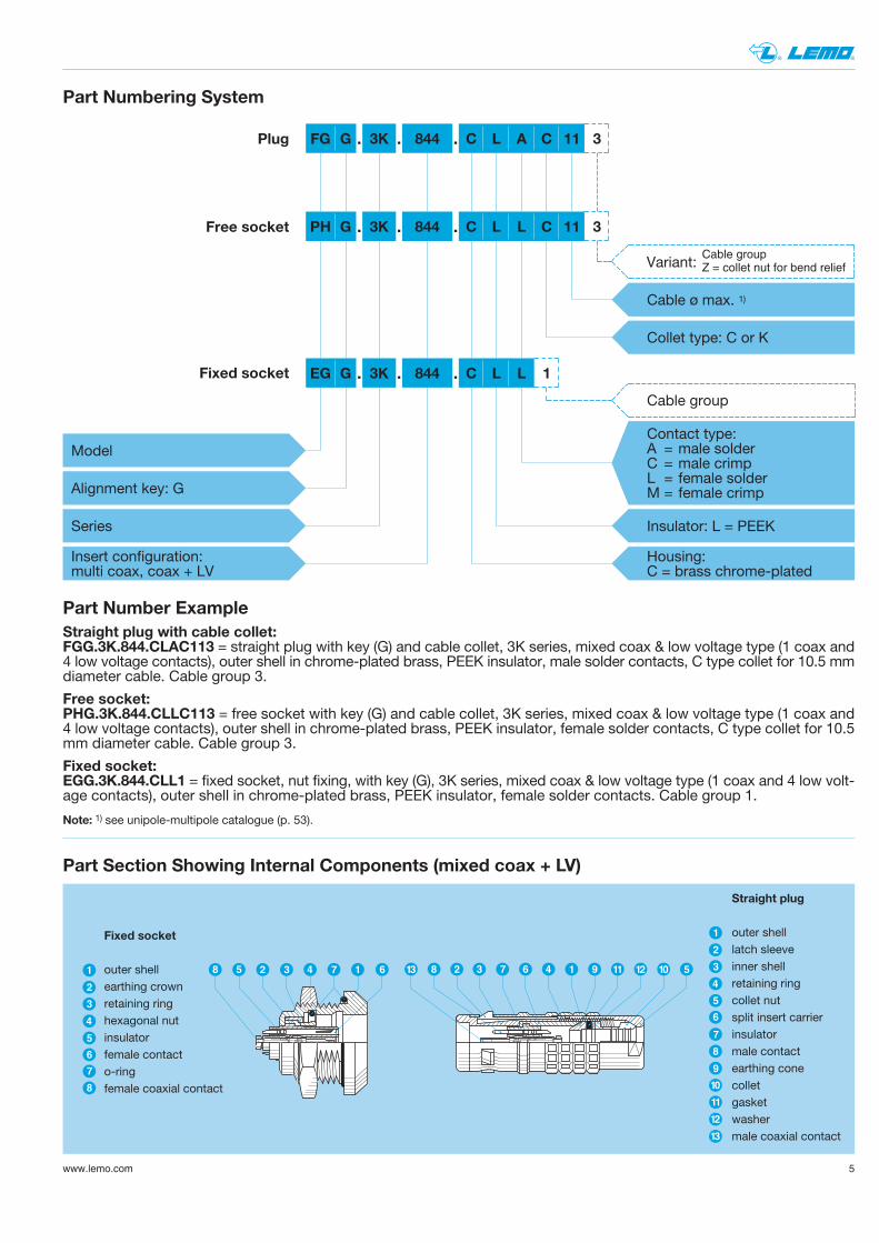
Fixed socket
outer shellearthing crownretaining ringhexagonal nutinsulatorfemale contacto-ringfemale coaxial contact
Straight plug
outer shelllatch sleeveinner shellretaining ringcollet nutsplit insert carrierinsulatormale contactearthing conecolletgasketwashermale coaxial contact
3
3
Straight plug with cable collet:FGG.3K.844.CLAC113 = straight plug with key (G) and cable collet, 3K series, mixed coax & low voltage type (1 coax and4 low voltage contacts), outer shell in chrome-plated brass, PEEK insulator, male solder contacts, C type collet for 10.5 mmdiameter cable. Cable group 3.
FG G 3K
Insert configuration:multi coax, coax + LV
Cable ø max. 1)
Collet type: C or K
844
Series
Model
Alignment key: G
C L A C 11
Fixed socket EG G 3K 844 C L L
Housing:C = brass chrome-plated
Insulator: L = PEEK
Contact type:A = male solderC = male crimpL = female solderM = female crimp
Fixed socket:EGG.3K.844.CLL1 = fixed socket, nut fixing, with key (G), 3K series, mixed coax & low voltage type (1 coax and 4 low volt-age contacts), outer shell in chrome-plated brass, PEEK insulator, female solder contacts. Cable group 1.
Cable group
Part Numbering System
Plug
PH G 3K 844 C L L C 11Free socket
Part Number Example
Free socket:PHG.3K.844.CLLC113 = free socket with key (G) and cable collet, 3K series, mixed coax & low voltage type (1 coax and4 low voltage contacts), outer shell in chrome-plated brass, PEEK insulator, female solder contacts, C type collet for 10.5mm diameter cable. Cable group 3.
. . .
. . .
. . . 1
Note: 1) see unipole-multipole catalogue (p. 53).
Cable groupZ = collet nut for bend reliefVariant:
6 www.lemo.com
® ®
ø A
Coax
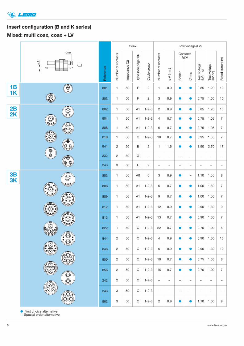
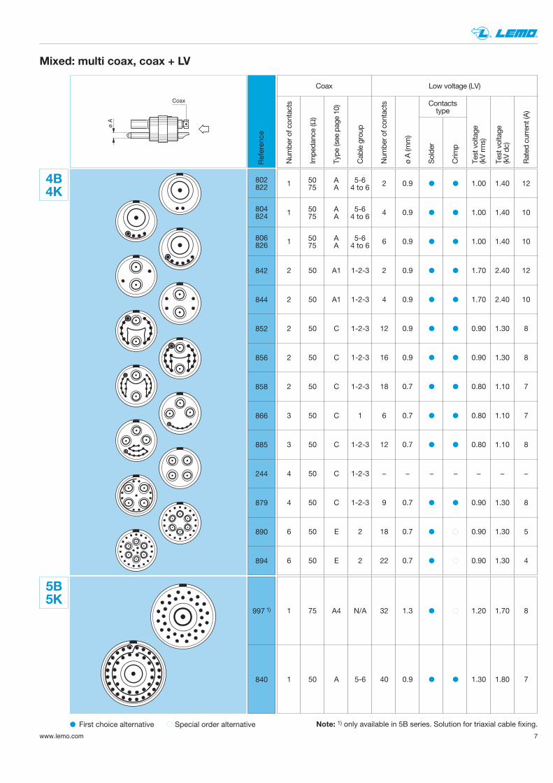
Mixed: multi coax, coax + LV
Referen
ce
1B1K
801
803
Num
ber o
f con
tacts
Impe
dance (Ω)
Type
(see pag
e 10
)
Cab
le group
Num
ber o
f con
tacts
ø A (m
m)
Solde
r
Crim
p
Test voltage
(kV rm
s)
Test voltage
(kV dc)
Rated
current (A
)
Coax Low voltage (LV)
Contactstype
1 50 F 2 1 0.9 0.85 1.20 10
1 50 F 2 3 0.9 0.75 1.05 10
2B2K
802
804
806
810
841
232
243
1 50 A1 1-2-3 2 0.9 0.85 1.20 10
1 50 A1 1-2-3 4 0.7 0.75 1.05 7
1 50 A1 1-2-3 6 0.7 0.75 1.05 7
1 50 C 1-2-3 10 0.7 0.95 1.35 7
2 50 E 2 1 1.6 1.90 2.70 17
2 50 G – – – – – – – –
3 50 E 2 – – – – – – –
B R
G
3B3K
803
806
809
812
813
822
844
846
850
856
242
243
862
1 50 A0 6 3 0.9 – 1.10 1.55 8
1 50 A1 1-2-3 6 0.7 1.00 1.50 7
1 50 A1 1-2-3 9 0.7 1.00 1.50 7
1 50 A1 1-2-3 12 0.9 0.90 1.30 9
1 50 A1 1-2-3 13 0.7 0.90 1.30 7
1 50 C 1-2-3 22 0.7 0.70 1.00 5
2 50 C 1-2-3 4 0.9 0.90 1.30 10
2 50 C 1-2-3 6 0.9 0.90 1.30 10
2 50 C 1-2-3 10 0.7 0.75 1.05 8
2 50 C 1-2-3 16 0.7 0.70 1.00 7
2 50 C 1-2-3 – – – – – – –
3 50 C 1-2-3 – – – – – – –
3 50 C 1-2-3 2 0.9 1.10 1.60 9
First choice alternative Special order alternative
Insert configuration (B and K series)
7www.lemo.com
® ®
842
844
852
856
858
866
885
244
879
890
894
802822
804824
806826
ø A
Coax
Mixed: multi coax, coax + LV
Referen
ce
4B4K
1 2 0.9 1.00 1.40 12
1 4 0.9 1.00 1.40 10
1 6 0.9 1.00 1.40 10
2 50 A1 1-2-3 2 0.9 1.70 2.40 12
2 50 A1 1-2-3 4 0.9 1.70 2.40 10
2 50 C 1-2-3 12 0.9 0.90 1.30 8
2 50 C 1-2-3 16 0.9 0.90 1.30 8
2 50 C 1-2-3 18 0.7 0.80 1.10 7
3 50 C 1 6 0.7 0.80 1.10 7
3 50 C 1-2-3 12 0.7 0.80 1.10 8
4 50 C 1-2-3 – – – – – – –
4 50 C 1-2-3 9 0.7 0.90 1.30 8
6 50 E 2 18 0.7 0.90 1.30 5
6 50 E 2 22 0.7 0.90 1.30 4
50 A 5-675 A 4 to 6
50 A 5-675 A 4 to 6
50 A 5-675 A 4 to 6
Num
ber o
f con
tacts
Impe
dance (Ω)
Type
(see pag
e 10
)
Cab
le group
Num
ber o
f con
tacts
ø A (m
m)
Solde
r
Crim
p
Test voltage
(kV rm
s)
Test voltage
(kV dc)
Rated
current (A
)
Coax Low voltage (LV)
Contactstype
5B5K
997 1)
840
1 75 A4 N/A 32 1.3 1.20 1.70 8
1 50 A 5-6 40 0.9 1.30 1.80 7
First choice alternative Special order alternative Note: 1) only available in 5B series. Solution for triaxial cable fixing.
868
864
273
274
892
260
240
8 www.lemo.com
® ®
ø A
Coax
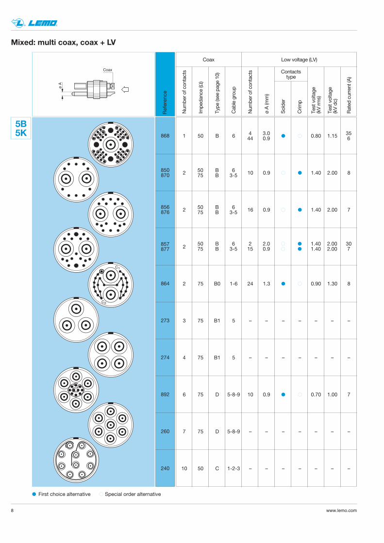
Mixed: multi coax, coax + LV
Referen
ce
C1
C2
5B5K 1 50 B 6 0.80 1.15
2 10 0.9 1.40 2.00 8
2 16 0.9 1.40 2.00 7
2
2 75 B0 1-6 24 1.3 0.90 1.30 8
3 75 B1 5 – – – – – – –
4 75 B1 5 – – – – – – –
6 75 D 5-8-9 10 0.9 0.70 1.00 7
7 75 D 5-8-9 – – – – – – –
10 50 C 1-2-3 – – – – – – –
50 B 675 B 3-5
50 B 675 B 3-5
50 B 6 2 2.0 1.40 2.00 3075 B 3-5 15 0.9 1.40 2.00 7
850870
856876
857877
Num
ber o
f con
tacts
Impe
dance (Ω)
Type
(see pag
e 10
)
Cab
le group
Num
ber o
f con
tacts
ø A (m
m)
Solde
r
Crim
p
Test voltage
(kV rm
s)
Test voltage
(kV dc)
Rated
current (A
)
Coax Low voltage (LV)
Contactstype
4 3.0 3544 0.9 6
First choice alternative Special order alternative
9www.lemo.com
® ®
ø A
Coax
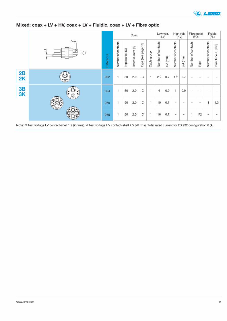
Mixed: coax + LV + HV, coax + LV + Fluidic, coax + LV + Fibre optic
Referen
ce
2B2K 932
Num
ber o
f con
tacts
Impe
dance (Ω)
Rated
current (A
)
Type
(see pag
e 10
)
Cab
le group
Num
ber o
f con
tacts
ø A (m
m)
Num
ber o
f con
tacts
ø A (m
m)
Num
ber o
f con
tacts
Type
Num
ber o
f con
tacts
Inner tub
e ø (m
m)
Coax Low volt.(LV)
High volt.(HV)
Fibre optic(FO)
Fluidic(FL)
1 50 2.0 C 1 21) 0.7 1 2) 0.7 – – – –
1 50 2.0 C 1 4 0.9 1 0.9 – – – –
1 50 2.0 C 1 10 0.7 – – – – 1 1.3
1 50 2.0 C 1 16 0.7 – – 1 F2 – –
3B3K
934
970
986
Note: 1) Test voltage LV contact-shell 1.9 (kV rms). 2) Test voltage HV contact-shell 7.5 (kV rms). Total rated current for 2B.932 configuration 6 (A).
10 www.lemo.com
® ®
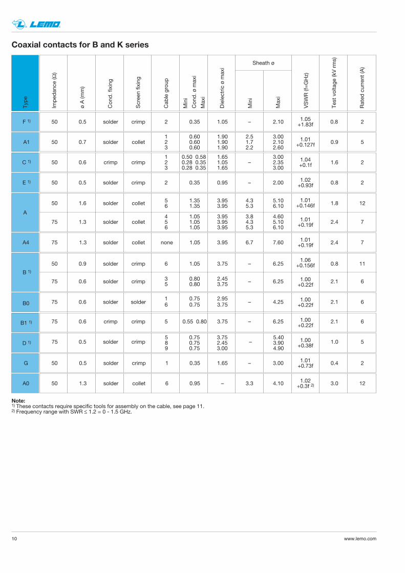
Coaxial contacts for B and K series
1 0.60 1.90 2.5 3.0050 0.7 solder collet 2 0.60 1.90 1.7 2.10 0.9 5
3 0.60 1.90 2.2 2.60
1.01+0.127f
1.04+0.1f
1.02+0.93f
1.05+1.83f
1 0.50 0.58 1.65 3.0050 0.6 crimp crimp 2 0.28 0.35 1.05 – 2.35 1.6 2
3 0.28 0.35 1.65 3.00
50 0.5 solder crimp 2 0.35 0.95 – 2.00 0.8 2
5 1.35 3.95 4.3 5.1050 1.6 solder collet 1.8 126 1.35 3.95 5.3 6.10
4 1.05 3.95 3.8 4.6075 1.3 solder collet 5 1.05 3.95 4.3 5.10 2.4 7
6 1.05 3.95 5.3 6.10
1.01+0.146f
A1.01+0.19f
1.01+0.19f
1.06+0.156f
1.00+0.22f
1.00+0.22f
1.00+0.22f
3.752.453.00
5.403.904.90
0.750.750.75
589
50 0.5 solder crimp 2 0.35 1.05 – 2.10 0.8 2
75 1.3 solder collet none 1.05 3.95 6.7 7.60 2.4 7
1 0.75 2.9575 0.6 solder solder – 4.25 2.1 66 0.75 3.75
75 0.6 crimp crimp 5 0.55 0.80 3.75 – 6.25 2.1 6
75 0.5 solder crimp – 1.0 5
Imped
ance
(Ω)
ø A (m
m)
Con
d. fixing
Scree
n fixing
Cab
le group
Con
d. ø
max
i
Dielectric
ø m
axi
Mini
Max
i
VSWR (f=GHz)
Test voltage
(kV rms)
Rated
current (A
)
Sheath ø
50 0.9 solder crimp 6 1.05 3.75 – 6.25 0.8 11
3 0.80 2.4575 0.6 solder crimp – 6.25 2.1 65 0.80 3.75
B 1)
Mini
Max
i
Note:1) These contacts require specific tools for assembly on the cable, see page 11.2) Frequency range with SWR ≤ 1.2 = 0 - 1.5 GHz.
50 0.5 solder crimp 1 0.35 1.65 – 3.00 0.4 2
50 1.3 solder collet 6 0.95 – 3.3 4.10 3.0 12
A1
C 1)
E 1)
F 1)
A4
B0
B1 1)
D 1)
G
A0
1.00+0.38f
1.01+0.73f
1.02+0.3f 2)
Type
11www.lemo.com
® ®
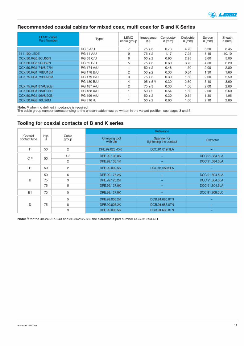
Recommended coaxial cables for mixed coax, multi coax for B and K Series
LEMO cablePart Number Type
311 100 LEDECCX.50.RG5.8CU50NCCX.50.RG5.9BU62NCCX.50.RG1.74AU27NCCX.50.RG1.78BU18MCCX.75.RG1.79BU26M
CCX.75.RG1.87AU26BCCX.50.RG1.88AU26BCCX.50.RG1.96AU20BCCX.50.RG3.16U26M
LEMO Impedance Conductor Dielectric Screen Sheathcable group (Ω) ø (mm) ø (mm) ø (mm) ø (mm)
RG 6 A/U 7 75 ± 3 0.73 4.70 6.20 8.45RG 11 A/U 9 75 ± 2 1.17 7.25 8.15 10.10RG 58 C/U 6 50 ± 2 0.90 2.95 3.60 5.00RG 59 B/U 5 75 ± 3 0.60 3.70 4.50 6.20RG 174 A/U 1 50 ± 2 0.48 1.50 2.00 2.80RG 178 B/U 2 50 ± 2 0.30 0.84 1.30 1.80RG 179 B/U 3 75 ± 3 0.30 1.50 2.00 2.50RG 180 B/U 4 95 ± 5 1) 0.30 2.60 3.10 3.60RG 187 A/U 2 75 ± 3 0.30 1.50 2.00 2.60RG 188 A/U 1 50 ± 2 0.54 1.50 2.00 2.60RG 196 A/U 1 50 ± 2 0.30 0.84 1.30 1.95RG 316 /U 1 50 ± 2 0.60 1.60 2.10 2.80
Note: 1) when no defined impedance is required.The cable group number corresponding to the chosen cable must be written in the variant position, see pages 3 and 5.
Reference
Tooling for coaxial contacts of B and K series
Coaxial Imp. Cablecontact type Ω group
F 50 2 DPE.99.025.45K DCC.91.019.1LA –
1-3 DPE.99.103.8K – DCC.91.384.5LAC 1) 50
2 DPE.99.103.1K – DCC.91.384.5LA
B1 75 5 DPE.99.127.0K – DCC.91.808.0LC
E 50 2 DPE.99.002.5K DCC.91.050.2LA –
50 6 DPE.99.176.2K – DCC.91.804.5LA
B 75 3 DPE.99.125.2K – DCC.91.804.5LA
75 5 DPE.99.127.0K – DCC.91.804.5LA
5 DPE.99.006.2K DCB.91.685.8TN –
D 75 8 DPE.99.005.2K DCB.91.685.8TN –
9 DPE.99.005.5K DCB.91.685.8TN –
Spanner fortightening the contact ExtractorCrimping tool
with die
Note: 1) for the 3B.243/3K.243 and 3B.862/3K.862 the extractor is part number DCC.91.393.4LT.
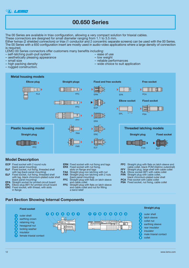
The 00 Series are available in triax configuration, allowing a very compact solution for triaxial cables. These connectors are designed for small diameter ranging from 1.1 to 3.5 mm. Either twinax (2 shielded connectors) or triax (1 conductor and 2 concentric separate screens) can be used with the 00 Series. The 00 Series with a 650 configuration insert are mostly used in audio-video applications where a large density of connectionis required. LEMO 00 Series connectors offer customers many benefits including:– self-latching push-pull system – ease of use– aesthetically pleasing appearance – low weight– small size – reliable performances– high packing density – wide choice to suit application– rugged construction.
FFC
FFC
EPA PCA
PSA
FAR
FAA
ERN
ECP
EPL
FFY
FLA
FFC
ERX
FVN
ERC
ELFELF
Elbow plug Straight plugs Fixed and free sockets
Elbow socket Fixed socket
Free socket
00.650 Series
Metal housing models
Plastic housing model
Straight plug
Threaded latching models
Straight plug Fixed socket
12 www.lemo.com
® ®
Part Section Showing Internal Components
14 5 267 3
43
12
1 45267 3
4
3
12
8
6
5
7
6
5
7
8
Fixed socket
outer shellearthing crownretaining ringhexagonal nutlocking washerinsulatorfemale triaxial contact
Straight plug
outer shelllatch sleevecollet nutearthing sleeverear insulatorinsulatormale triaxial contactcollet
Model DescriptionECP Fixed socket with 2 round nuts
(back panel mounting)ELF Fixed socket, nut fixing, threaded shell
with tag (back panel mounting)ELF Fixed socket, nut fixing, threaded shell
with tag, black chromium-plated outer shell(back panel mounting)
EPA Straight socket for printed circuit boardEPL Elbow plug (90°) for printed circuit boardERC Fixed socket, with thread, with slots
in flange
ERN Fixed socket with nut fixing and tagsERX Fixed socket with nut fixing,
slots on flange and tagsFAA Straight plug non latching with nutFAR Straight plug non latching with 2 nuts
(back panel mounting)FFC Straight plug with flats on latch sleeve
and cable colletFFC Straight plug with flats on latch sleeve
and cable collet and nut for fitting a bend relief
FFC Straight plug with flats on latch sleeve andcable collet, black POM (Delrin® outershell)
FFY Straight plug, large shell with cable colletFLA Elbow socket (90°) with cable colletFVN Straight plug with cable collet,
black chromium-plated outer shell PCA Free socket with cable colletPSA Fixed socket, nut fixing, cable collet
13www.lemo.com
® ®
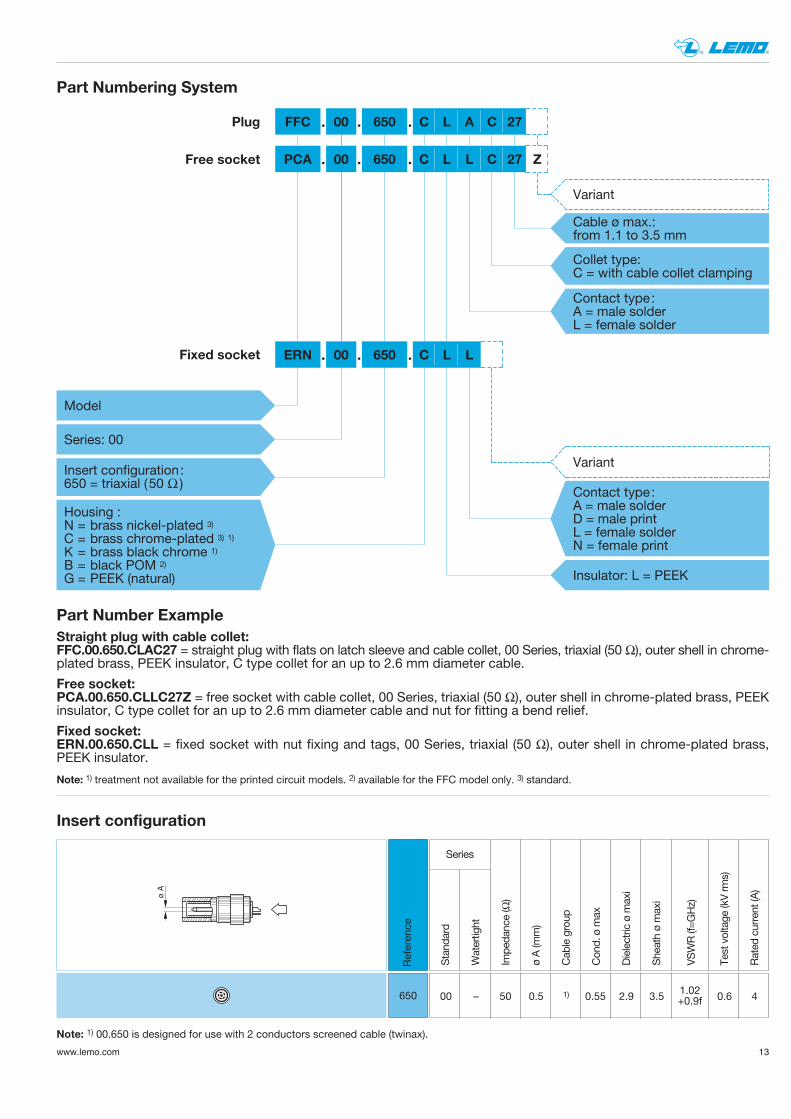
Straight plug with cable collet:FFC.00.650.CLAC27 = straight plug with flats on latch sleeve and cable collet, 00 Series, triaxial (50 Ω), outer shell in chrome-plated brass, PEEK insulator, C type collet for an up to 2.6 mm diameter cable.
Fixed socket:ERN.00.650.CLL = fixed socket with nut fixing and tags, 00 Series, triaxial (50 Ω), outer shell in chrome-plated brass, PEEK insulator.
Part Numbering System
Part Number Example
Free socket:PCA.00.650.CLLC27Z = free socket with cable collet, 00 Series, triaxial (50 Ω), outer shell in chrome-plated brass, PEEK insulator, C type collet for an up to 2.6 mm diameter cable and nut for fitting a bend relief.
PCA
FFC
Z
00
Cable ø max.:from 1.1 to 3.5 mm
Collet type: C = with cable collet clamping
650
Insert configuration:650 = triaxial (50 Ω )
Housing : N = brass nickel-plated 3)C = brass chrome-plated 3) 1)K = brass black chrome 1)B = black POM 2)G = PEEK (natural)
Model
Series: 00
C L A C 27
Fixed socket ERN 00 650 C L L
Insulator: L = PEEK
Variant
Plug
00 650 C L L C 27Free socket
. . .
. . .
. . .
Variant
Contact type:A = male solderL = female solder
Contact type:A = male solderD = male printL = female solderN = female print
Note: 1) treatment not available for the printed circuit models. 2) available for the FFC model only. 3) standard.
ø A
Stand
ard
Watertight
Impe
dance (Ω)
ø A (m
m)
Cab
le group
Con
d. ø m
ax
Dielectric ø m
axi
Sheath ø maxi
VSWR (f=G
Hz)
Test voltage
(kV rm
s)
Rated
current (A
)
Series
00 – 50 0.5 1) 0.55 2.9 3.5 0.6 4
Referen
ce
1.02+0.9f650
Note: 1) 00.650 is designed for use with 2 conductors screened cable (twinax).
Insert configuration
HGP
HGW
EWB
FTR
FFA, FFP
FFA, FFP
FFA
FFF
FFS
FLAFLS
FZP
FAA
FRT
FFB
PCA, PCP
PCA
PCAPSS
SWH
RAD
RMA
FFE
ERN
FFL
ERA
ERC
ERN
EBD
EBS
EBC
ECP
ERD
PSA, PSP
EHP
HCP
FFA, FFPFFP
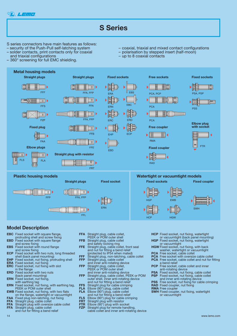
S series connectors have main features as follows:– security of the Push-Pull self-latching system – coaxial, triaxial and mixed contact configurations– solder contacts, print contacts only for coaxial – polarisation by stepped insert (half-moon)and triaxial configurations – up to 8 coaxial contacts
– 360° screening for full EMC shielding.
Watertight or vacuumtight modelsPlastic housing modelsFixed socketsFixed socketStraight plugs Fixed coupler
Straight plugs
Straight plug with resistor
Straight plugs Fixed sockets Free sockets Fixed sockets
Free couplerFixed plug
Elbow plugs Fixed coupler
Elbow plug with socket
S Series
Metal housing models
14 www.lemo.com
® ®
EBC Fixed socket with square flange, protruding shell and screw fixing
EBD Fixed socket with square flange and screw fixing
EBS Fixed socket with round flange and screw fixing
ECP Fixed socket with two nuts, long threadedshell (back panel mounting)
EHP Fixed socket, nut fixing, protruding shell ERA Fixed socket, nut fixingERC Fixed socket, nut fixing with slot
in the flangeERD Fixed socket with two nuts
(back panel mounting)ERN Fixed socket, nut fixing,
with earthing tagERN Fixed socket, nut fixing, with earthing tag,
PEEK or POM outer shellEWB Fixed socket, nut fixing, with two flats
on the flange, watertight or vacuumtightFAA Fixed plug non-latching, nut fixingFFA Straight plug, cable colletFFA Straight plug with oversize cable colletFFA Straight plug, cable collet
and nut for fitting a bend relief
FFA Straight plug, cable collet, PEEK or POM outer shell
FFB Straight plug, cable collet and safety locking ring
FFE Straight plug, cable collet, front seal and nut for fitting a bend relief (protected to IP54 when mated)
FFF Straight plug, non-latching, cable colletFFP Straight plug, cable collet
and inner anti-rotating deviceFFP Straight plug, cable collet,
PEEK or POM outer shell and inner anti-rotating device
FFP Straight plug, cable collet, PEEK or POM outer shell, inner anti-rotating device and nut for fitting a bend relief
FFS Straight plug for cable crimpingFLA Elbow (90°) plug, cable colletFLA Elbow (90°) plug, cable collet
and nut for fitting a bend reliefFLS Elbow (90°) plug for cable crimpingFRT Straight plug with resistorFTR Elbow (90°) plug with socketFZP Straight plug for remote handling,
cable collet and inner anti-rotating device
HCP Fixed socket, nut fixing, watertight or vacuumtight (back panel mounting)
HGP Fixed socket, nut fixing, watertight or vacuumtight
HGW Fixed socket, nut fixing, with backwasher, watertight or vacuumtight
PCA Free socket, cable colletPCA Free socket with oversize cable colletPCA Free socket, cable collet and nut for fitting
a bend reliefPCP Free socket, cable collet and inner
anti-rotating devicePSA Fixed socket, nut fixing, cable colletPSP Fixed socket, nut fixing, cable collet
and inner anti-rotating devicePSS Free socket, nut fixing for cable crimpingRAD Fixed coupler, nut fixingRMA Free couplerSWH Fixed coupler, nut fixing, watertight
or vacuumtight
Model Description
15www.lemo.com
® ®
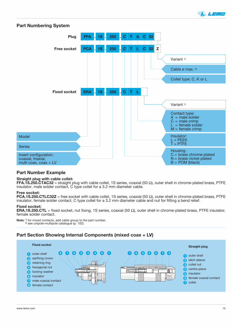
Part Section Showing Internal Components (mixed coax + LV)
1 4 36 5 2 7
4
3
1
2
6
5
7
8
4
3
1
2
6
5
7
542 36 178
Fixed socket
outer shellearthing crownretaining ringhexagonal nutlocking washerinsulatormale coaxial contactfemale contact
Straight plug
outer shelllatch sleevecollet nutcentre-pieceinsulatorfemale coaxial contactcollet
Straight plug with cable collet:FFA.1S.250.CTAC32 = straight plug with cable collet, 1S series, coaxial (50 Ω), outer shell in chrome-plated brass, PTFEinsulator, male solder contact, C type collet for a 3.2 mm diameter cable.
FFA 1S
Insert configuration:coaxial, triaxial, multi coax, coax + LV
Cable ø max. 2)
Collet type: C, K or L
250
Series
Model
C T A C 32
Fixed socket ERA 1S 250 C T L
Housing:C = brass chrome-platedN = brass nickel-platedB = POM (black)
Insulator: L = PEEKT = PTFE
Contact type:A = male solderC = male crimpL = female solderM = female crimp
Fixed socket:ERA.1S.250.CTL = fixed socket, nut fixing, 1S series, coaxial (50 Ω), outer shell in chrome-plated brass, PTFE insulator,female solder contact.
Variant 1)
Part Numbering System
Plug
PCA 1S 250 C T L C 32 ZFree socket
Part Number Example
Free socket:PCA.1S.250.CTLC32Z = free socket with cable collet, 1S series, coaxial (50 Ω), outer shell in chrome-plated brass, PTFEinsulator, female solder contact, C type collet for a 3.2 mm diameter cable and nut for fitting a bend relief.
. . .
. . .
. . .
Note: 1) for mixed contacts, add cable group to the part number.2) see unipole-multipole catalogue (p. 102).
Variant 1)
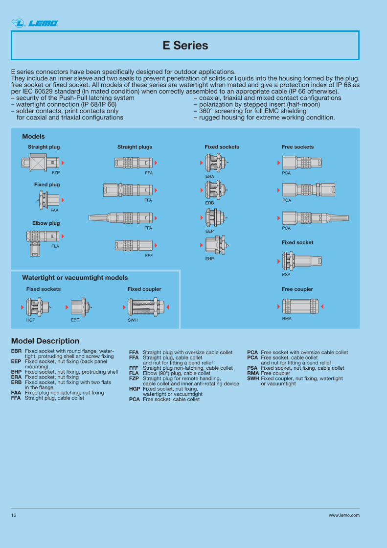
E series connectors have been specifically designed for outdoor applications.They include an inner sleeve and two seals to prevent penetration of solids or liquids into the housing formed by the plug,free socket or fixed socket. All models of these series are watertight when mated and give a protection index of IP 68 asper IEC 60529 standard (in mated condition) when correctly assembled to an appropriate cable (IP 66 otherwise).– security of the Push-Pull latching system – coaxial, triaxial and mixed contact configurations– watertight connection (IP 68/IP 66) – polarization by stepped insert (half-moon)– solder contacts, print contacts only – 360° screening for full EMC shieldingfor coaxial and triaxial configurations – rugged housing for extreme working condition.
FFA
FFA
FFA
FZP
FFF
FAA
FLA
HGP
ERAPCA
PCA
PSA
PCA
SWH
EHP
ERB
EBR RMA
EEP
Watertight or vacuumtight models
Fixed sockets
Straight plug
Fixed plug
Elbow plug
Straight plugs Fixed sockets Free sockets
Fixed socket
Free couplerFixed coupler
E Series
Models
16 www.lemo.com
® ®
Model DescriptionEBR Fixed socket with round flange, water-
tight, protruding shell and screw fixingEEP Fixed socket, nut fixing (back panel
mounting)EHP Fixed socket, nut fixing, protruding shellERA Fixed socket, nut fixingERB Fixed socket, nut fixing with two flats
in the flange FAA Fixed plug non-latching, nut fixingFFA Straight plug, cable collet
FFA Straight plug with oversize cable colletFFA Straight plug, cable collet
and nut for fitting a bend reliefFFF Straight plug non-latching, cable colletFLA Elbow (90°) plug, cable colletFZP Straight plug for remote handling,
cable collet and inner anti-rotating deviceHGP Fixed socket, nut fixing,
watertight or vacuumtightPCA Free socket, cable collet
PCA Free socket with oversize cable colletPCA Free socket, cable collet
and nut for fitting a bend reliefPSA Fixed socket, nut fixing, cable colletRMA Free couplerSWH Fixed coupler, nut fixing, watertight
or vacuumtight
17www.lemo.com
® ®
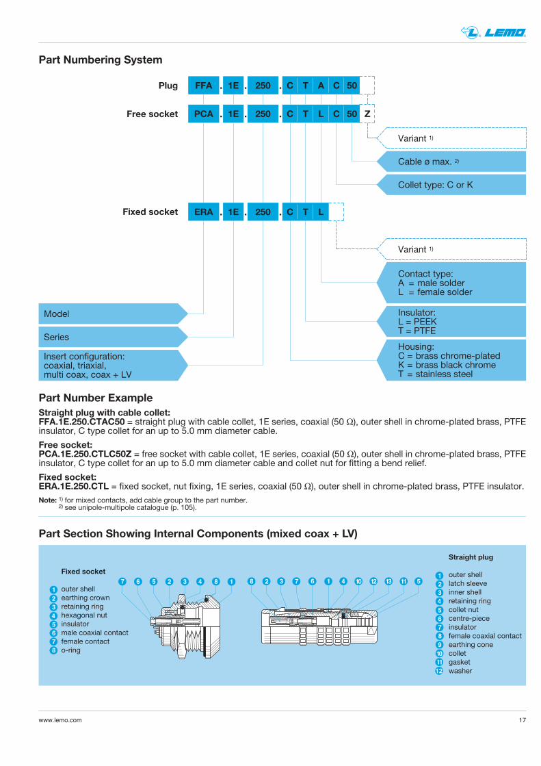
Part Section Showing Internal Components (mixed coax + LV)
4
5
3
6
8
7
1
2
6
7
1
2
5
4
3
8
9
10
11
12
5 8 1432 3 7 6 1 4 10 12 138 27 6 511
Fixed socket
outer shellearthing crownretaining ringhexagonal nutinsulatormale coaxial contactfemale contacto-ring
Straight plug
outer shelllatch sleeveinner shellretaining ringcollet nutcentre-pieceinsulatorfemale coaxial contactearthing conecolletgasketwasher
Straight plug with cable collet:FFA.1E.250.CTAC50 = straight plug with cable collet, 1E series, coaxial (50 Ω), outer shell in chrome-plated brass, PTFEinsulator, C type collet for an up to 5.0 mm diameter cable.
FFA 1E
Insert configuration:coaxial, triaxial, multi coax, coax + LV
Cable ø max. 2)
Collet type: C or K
Variant 1)
250
Series
Model
C T A C 50
Fixed socket ERA 1E 250 C T L
Housing:C = brass chrome-platedK = brass black chromeT = stainless steel
Insulator: L = PEEKT = PTFE
Contact type:A = male solderL = female solder
Fixed socket:ERA.1E.250.CTL = fixed socket, nut fixing, 1E series, coaxial (50 Ω), outer shell in chrome-plated brass, PTFE insulator.
Variant 1)
Part Numbering System
Plug
PCA 1E 250 C T L C 50 ZFree socket
Part Number Example
Free socket:PCA.1E.250.CTLC50Z = free socket with cable collet, 1E series, coaxial (50 Ω), outer shell in chrome-plated brass, PTFEinsulator, C type collet for an up to 5.0 mm diameter cable and collet nut for fitting a bend relief.
. . .
. . .
. . .
Note: 1) for mixed contacts, add cable group to the part number.2) see unipole-multipole catalogue (p. 105).
18 www.lemo.com
® ®
Stand
ard
Watertight
Impe
dance (Ω)
ø A (m
m)
Cab
le group
Con
d. ø m
ax
Dielectric ø m
axi
Maxi S
series
Maxi E series
VSWR (f=G
Hz)
Test voltage
(kV rm
s)
Rated
current (A
)
Sheath øSeries
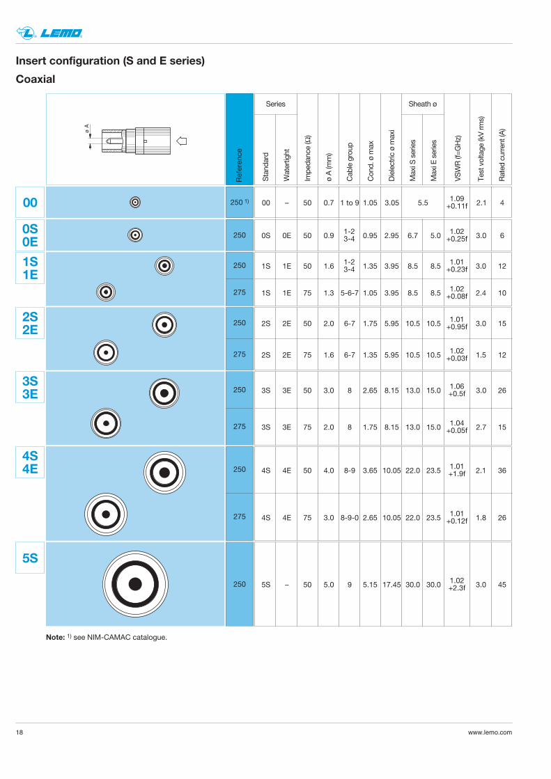
00 – 50 0.7 1 to 9 1.05 3.05 5.5 2.1 41.09+0.11f
ø A
Coaxial
Referen
ce0S 0E 50 0.9 0.95 2.95 6.7 5.0 3.0 61.02
+0.25f1-23-4
1-23-41S 1E 50 1.6 1.35 3.95 8.5 8.5 3.0 12
1S 1E 75 1.3 5-6-7 1.05 3.95 8.5 8.5 2.4 10
1.01+0.23f
1.02+0.08f
250 1)
250
275
00
2500S0E
2S 2E 50 2.0 6-7 1.75 5.95 10.5 10.5 3.0 15
2S 2E 75 1.6 6-7 1.35 5.95 10.5 10.5 1.5 12
1.01+0.95f
1.02+0.03f
3S 3E 50 3.0 8 2.65 8.15 13.0 15.0 3.0 26
3S 3E 75 2.0 8 1.75 8.15 13.0 15.0 2.7 15
1.06+0.5f
1.04+0.05f
4S 4E 50 4.0 8-9 3.65 10.05 22.0 23.5 2.1 36
4S 4E 75 3.0 8-9-0 2.65 10.05 22.0 23.5 1.8 26
1.01+1.9f
1.01+0.12f
5S – 50 5.0 9 5.15 17.45 30.0 30.0 3.0 451.02+2.3f
Note: 1) see NIM-CAMAC catalogue.
1S1E
250
275
2S2E
250
275
3S3E
250
275
4S4E
250
5S
Insert configuration (S and E series)
19www.lemo.com
® ®
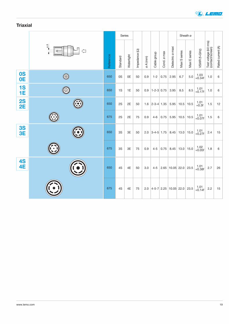
ø A
Triaxial
1S1E
2S2E
3S3E
4S4E
0S0E
Stand
ard
Watertight
Impe
dance (Ω)
ø A (m
m)
Cab
le group
Con
d. ø m
ax
Dielectric ø m
axi
Maxi S
series
Maxi E series
VSWR (f=G
Hz)
Test voltage
(kV rm
s)(con
tact/screen)
Rated
current (A
)
Sheath øSeries
Referen
ce
0S 0E 50 0.9 1-2 0.75 2.95 6.7 5.0 1.0 61.03+0.34f650
1S 1E 50 0.9 1-2-3 0.75 3.95 8.5 8.5 1.0 61.01+0.17f650
2S 2E 50 1.6 2-3-4 1.35 5.95 10.5 10.5 1.5 12
2S 2E 75 0.9 4-6 0.75 5.95 10.5 10.5 1.5 6
1.01+0.3f
1.01+0.07f
3S 3E 50 2.0 3-4-5 1.75 8.45 13.0 15.0 2.4 15
3S 3E 75 0.9 4-5 0.75 8.45 13.0 15.0 1.8 6
1.01+0.27f
1.02+0.05f
650
675
650
675
4S 4E 50 3.0 4-5 2.65 10.05 22.0 23.5 2.7 26
4S 4E 75 2.0 4-5-7 2.25 10.05 22.0 23.5 2.2 15
1.01+0.38f
1.01+0.14f
650
675
20 www.lemo.com
® ®
Stand
ard
Watertight
Num
ber o
f con
tacts
Impe
dance (Ω)
Rated
current (A
)
Type
(see pag
e 27
)
Cab
le group
Num
ber o
f con
tacts
ø A (m
m)
Test voltage
(kV rm
s)
Test voltage
(kV dc
)
Rated
current (A
)
CoaxialSeries Low Voltage
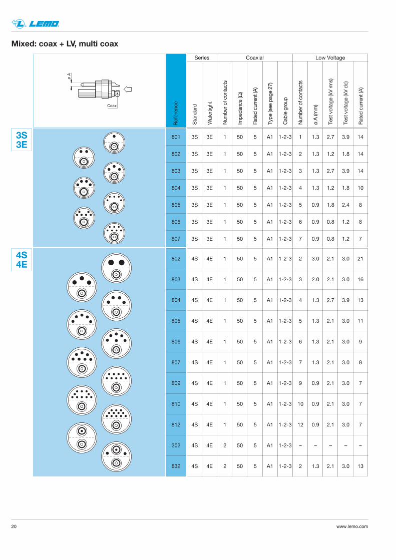
801
802
803
804
805
806
807
Mixed: coax + LV, multi coax
ø A
Coax
Referen
ce
3S3E
3S 3E 1 50 5 A1 1-2-3 1 1.3 2.7 3.9 14
3S 3E 1 50 5 A1 1-2-3 2 1.3 1.2 1.8 14
3S 3E 1 50 5 A1 1-2-3 3 1.3 2.7 3.9 14
3S 3E 1 50 5 A1 1-2-3 4 1.3 1.2 1.8 10
3S 3E 1 50 5 A1 1-2-3 5 0.9 1.8 2.4 8
3S 3E 1 50 5 A1 1-2-3 6 0.9 0.8 1.2 8
3S 3E 1 50 5 A1 1-2-3 7 0.9 0.8 1.2 7
802
803
804
805
806
807
809
810
812
202
832
4S4E
4S 4E 1 50 5 A1 1-2-3 2 3.0 2.1 3.0 21
4S 4E 1 50 5 A1 1-2-3 3 2.0 2.1 3.0 16
4S 4E 1 50 5 A1 1-2-3 4 1.3 2.7 3.9 13
4S 4E 1 50 5 A1 1-2-3 5 1.3 2.1 3.0 11
4S 4E 1 50 5 A1 1-2-3 6 1.3 2.1 3.0 9
4S 4E 1 50 5 A1 1-2-3 7 1.3 2.1 3.0 8
4S 4E 1 50 5 A1 1-2-3 9 0.9 2.1 3.0 7
4S 4E 1 50 5 A1 1-2-3 10 0.9 2.1 3.0 7
4S 4E 1 50 5 A1 1-2-3 12 0.9 2.1 3.0 7
4S 4E 2 50 5 A1 1-2-3 – – – – –
4S 4E 2 50 5 A1 1-2-3 2 1.3 2.1 3.0 13
21www.lemo.com
® ®
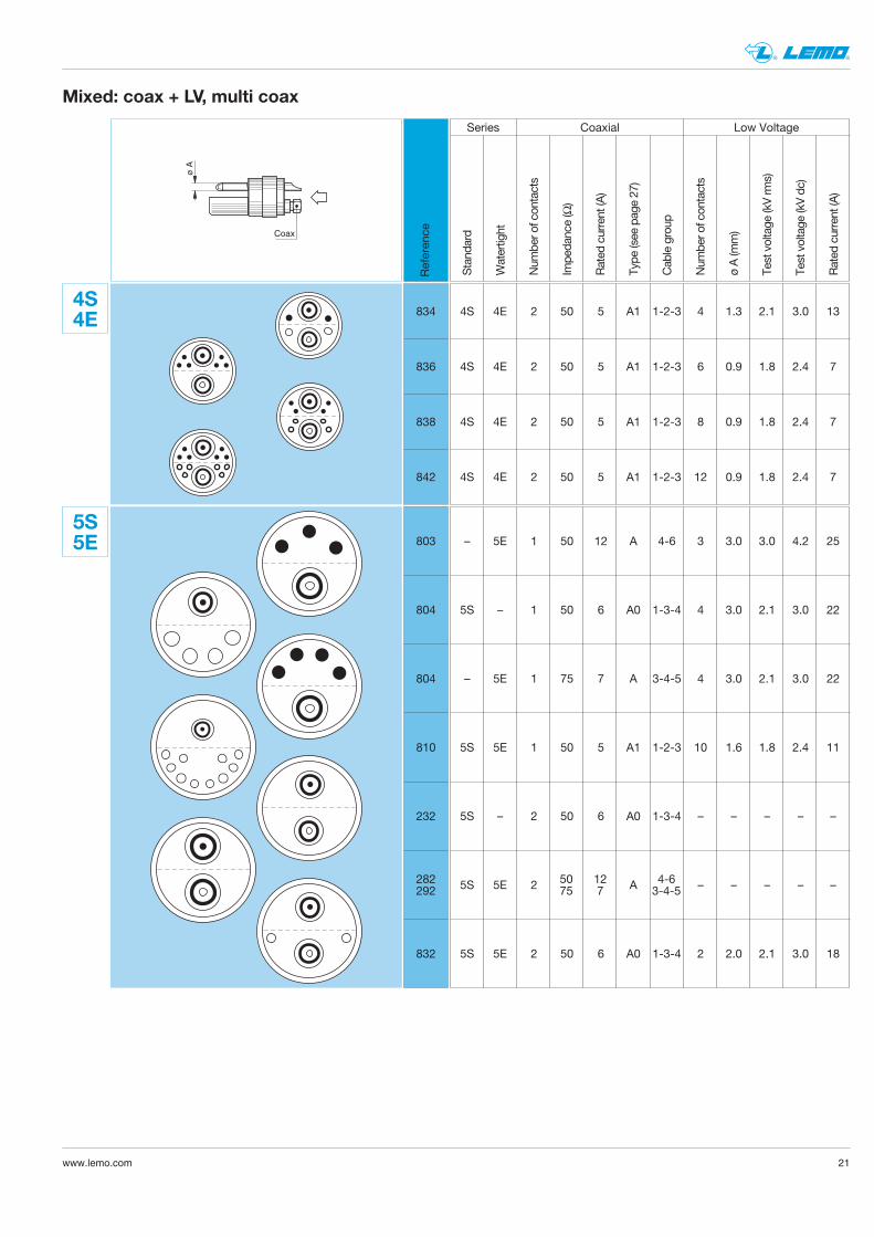
834
836
838
842
Mixed: coax + LV, multi coax
4S4E 4S 4E 2 50 5 A1 1-2-3 4 1.3 2.1 3.0 13
4S 4E 2 50 5 A1 1-2-3 6 0.9 1.8 2.4 7
4S 4E 2 50 5 A1 1-2-3 8 0.9 1.8 2.4 7
4S 4E 2 50 5 A1 1-2-3 12 0.9 1.8 2.4 7
803
804
804
810
232
832
5S5E – 5E 1 50 12 A 4-6 3 3.0 3.0 4.2 25
5S – 1 50 6 A0 1-3-4 4 3.0 2.1 3.0 22
– 5E 1 75 7 A 3-4-5 4 3.0 2.1 3.0 22
5S 5E 1 50 5 A1 1-2-3 10 1.6 1.8 2.4 11
5S – 2 50 6 A0 1-3-4 – – – – –
5S 5E 2 A – – – – –
5S 5E 2 50 6 A0 1-3-4 2 2.0 2.1 3.0 18
Stand
ard
Watertight
Num
ber o
f con
tacts
Impe
dance (Ω)
Rated
current (A
)
Type
(see pag
e 27
)
Cab
le group
Num
ber o
f con
tacts
ø A (m
m)
Test voltage
(kV rm
s)
Test voltage
(kV dc
)
Rated
current (A
)
CoaxialSeries Low Voltage
ø A
Coax
Referen
ce
282292
50 12 4-675 7 3-4-5
22 www.lemo.com
® ®
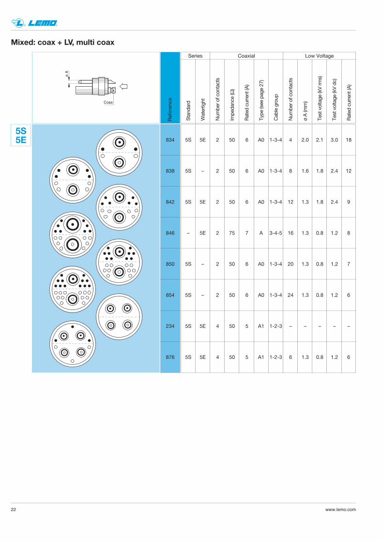
834
838
842
846
850
854
234
876
Mixed: coax + LV, multi coax
5S5E 5S 5E 2 50 6 A0 1-3-4 4 2.0 2.1 3.0 18
5S – 2 50 6 A0 1-3-4 8 1.6 1.8 2.4 12
5S 5E 2 50 6 A0 1-3-4 12 1.3 1.8 2.4 9
– 5E 2 75 7 A 3-4-5 16 1.3 0.8 1.2 8
5S – 2 50 6 A0 1-3-4 20 1.3 0.8 1.2 7
5S – 2 50 6 A0 1-3-4 24 1.3 0.8 1.2 6
5S 5E 4 50 5 A1 1-2-3 – – – – –
5S 5E 4 50 5 A1 1-2-3 6 1.3 0.8 1.2 6
Stand
ard
Watertight
Num
ber o
f con
tacts
Impe
dance (Ω)
Rated
current (A
)
Type
(see pag
e 27
)
Cab
le group
Num
ber o
f con
tacts
ø A (m
m)
Test voltage
(kV rm
s)
Test voltage
(kV dc
)
Rated
current (A
)
CoaxialSeries Low Voltage
ø A
Coax
Referen
ce
23www.lemo.com
® ®
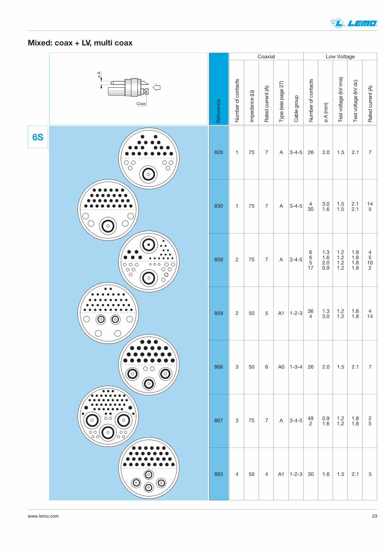
826
830
858
859
866
867
883
6S
1 75 7 A 3-4-5 26 2.0 1.5 2.1 7
1 75 7 A 3-4-5
2 75 7 A 3-4-5
2 50 5 A1 1-2-3
3 50 6 A0 1-3-4 26 2.0 1.5 2.1 7
3 75 7 A 3-4-5
4 50 4 A1 1-2-3 30 1.6 1.5 2.1 5
Mixed: coax + LV, multi coax
ø A
Coax
Num
ber o
f con
tacts
Impe
dance (Ω)
Rated
current (A
)
Type
(see pag
e 27
)
Cab
le group
Num
ber o
f con
tacts
ø A (m
m)
Test voltage
(kV rm
s)
Test voltage
(kV dc
)
Rated
current (A
)
Coaxial Low Voltage
Referen
ce
4 3.0 1.5 2.1 1430 1.6 1.5 2.1 5
6 1.3 1.2 1.8 46 1.6 1.2 1.8 55 2.0 1.2 1.8 1017 0.9 1.2 1.8 2
36 1.3 1.2 1.8 44 3.0 1.2 1.8 14
49 0.9 1.2 1.8 22 1.6 1.2 1.8 5
24 www.lemo.com
® ®
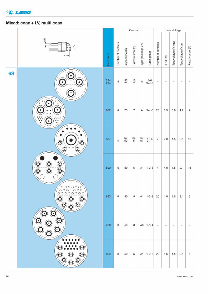
882
887
890
893
238
899
6S
4 A – – – – –
4 75 7 A 3-4-5 26 0.9 0.8 1.2 2
7 2.0 1.5 2.1 10
6 50 5 A1 1-2-3 4 4.0 1.5 2.1 16
6 50 5 A1 1-2-3 20 1.6 1.5 2.1 5
8 50 6 A0 1-3-4 – – – – –
8 50 5 A1 1-2-3 20 1.6 1.5 2.1 5
Mixed: coax + LV, multi coax
ø A
Coax
Num
ber o
f con
tacts
Impe
dance (Ω)
Rated
current (A
)
Type
(see pag
e 27
)
Cab
le group
Num
ber o
f con
tacts
ø A (m
m)
Test voltage
(kV rm
s)
Test voltage
(kV dc
)
Rated
current (A
)
Coaxial Low Voltage
Referen
ce
1 50 26 A34 50 5 A1
7 93
50 12 4-675 7 3-4-5
284294
25www.lemo.com
® ®
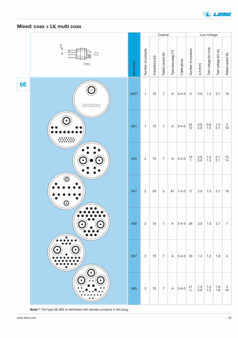
8051)
831
843
847
856
857
865
6E
1 75 7 A 3-4-5 5 2.0 1.5 2.1 10
1 75 7 A 3-4-5
2 75 7 A 3-4-5
2 50 5 A1 1-2-3 17 2.0 1.5 2.1 10
2 75 7 A 3-4-5 26 2.0 1.5 2.1 7
2 75 7 A 3-4-5 33 1.3 1.2 1.8 4
3 75 7 A 3-4-5
Mixed: coax + LV, multi coax
24 0.9 0.8 1.2 212 2.0 1.5 2.1 10
12 2.0 1.5 2.1 101 3.0 1.5 2.1 14
ø A
Coax
Num
ber o
f con
tacts
Impe
dance (Ω)
Rated
current (A
)
Type
(see pag
e 27
)
Cab
le group
Num
ber o
f con
tacts
ø A (m
m)
Test voltage
(kV rm
s)
Test voltage
(kV dc
)
Rated
current (A
)
Coaxial Low Voltage
Referen
ce
21 1.3 1.2 1.8 44 2.0 1.2 1.8 10
Note:1) The type 6E.805 is delivered with female contacts in the plug.
26 www.lemo.com
® ®
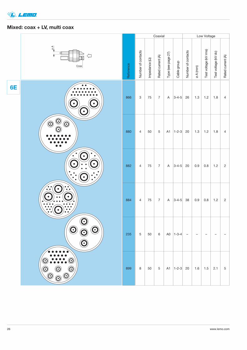
866
880
882
884
235
899
6E
3 75 7 A 3-4-5 26 1.3 1.2 1.8 4
4 50 5 A1 1-2-3 20 1.3 1.2 1.8 4
4 75 7 A 3-4-5 20 0.9 0.8 1.2 2
4 75 7 A 3-4-5 38 0.9 0.8 1.2 2
5 50 6 A0 1-3-4 – – – – –
8 50 5 A1 1-2-3 20 1.6 1.5 2.1 5
Mixed: coax + LV, multi coax
ø A
Coax
Num
ber o
f con
tacts
Impe
dance (Ω)
Rated
current (A
)
Type
(see pag
e 27
)
Cab
le group
Num
ber o
f con
tacts
ø A (m
m)
Test voltage
(kV rm
s)
Test voltage
(kV dc
)
Rated
current (A
)
Coaxial Low Voltage
Referen
ce
www.lemo.com
® ®
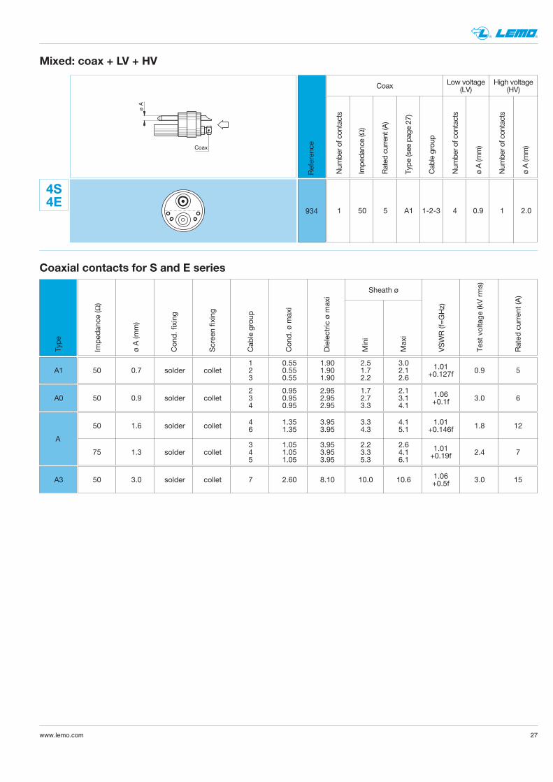
Mixed: coax + LV + HV
Referen
ce
4S4E
934
Num
ber o
f con
tacts
Impe
dance (Ω)
Rated
current (A
)
Type
(see pag
e 27
)
Cab
le group
Num
ber o
f con
tacts
ø A (m
m)
Num
ber o
f con
tacts
ø A (m
m)
Coax Low voltage(LV)
High voltage(HV)
1 50 5 A1 1-2-3 4 0.9 1 2.0
ø A
Coax
1 0.55 1.90 2.5 3.050 0.7 solder collet 2 0.55 1.90 1.7 2.1 0.9 5
3 0.55 1.90 2.2 2.6
1.01+0.127f
2 0.95 2.95 1.7 2.150 0.9 solder collet 3 0.95 2.95 2.7 3.1 3.0 6
4 0.95 2.95 3.3 4.1
1.06+0.1f
4 1.35 3.95 3.3 4.150 1.6 solder collet 1.8 126 1.35 3.95 4.3 5.1
3 1.05 3.95 2.2 2.675 1.3 solder collet 4 1.05 3.95 3.3 4.1 2.4 7
5 1.05 3.95 5.3 6.1
1.01+0.146f
1.01+0.19f
50 3.0 solder collet 7 2.60 8.10 10.0 10.6 3.0 151.06+0.5f
Coaxial contacts for S and E series
Imped
ance
(Ω)
ø A (m
m)
Con
d. fixing
Scree
n fixing
Cab
le group
Con
d. ø
max
i
Dielectric
ø m
axi
Mini
Max
i
VSWR (f=GHz)
Test voltage
(kV rms)
Rated
current (A
)
Sheath ø
A1
A0
A
A3
Type
27
28 www.lemo.com
® ®
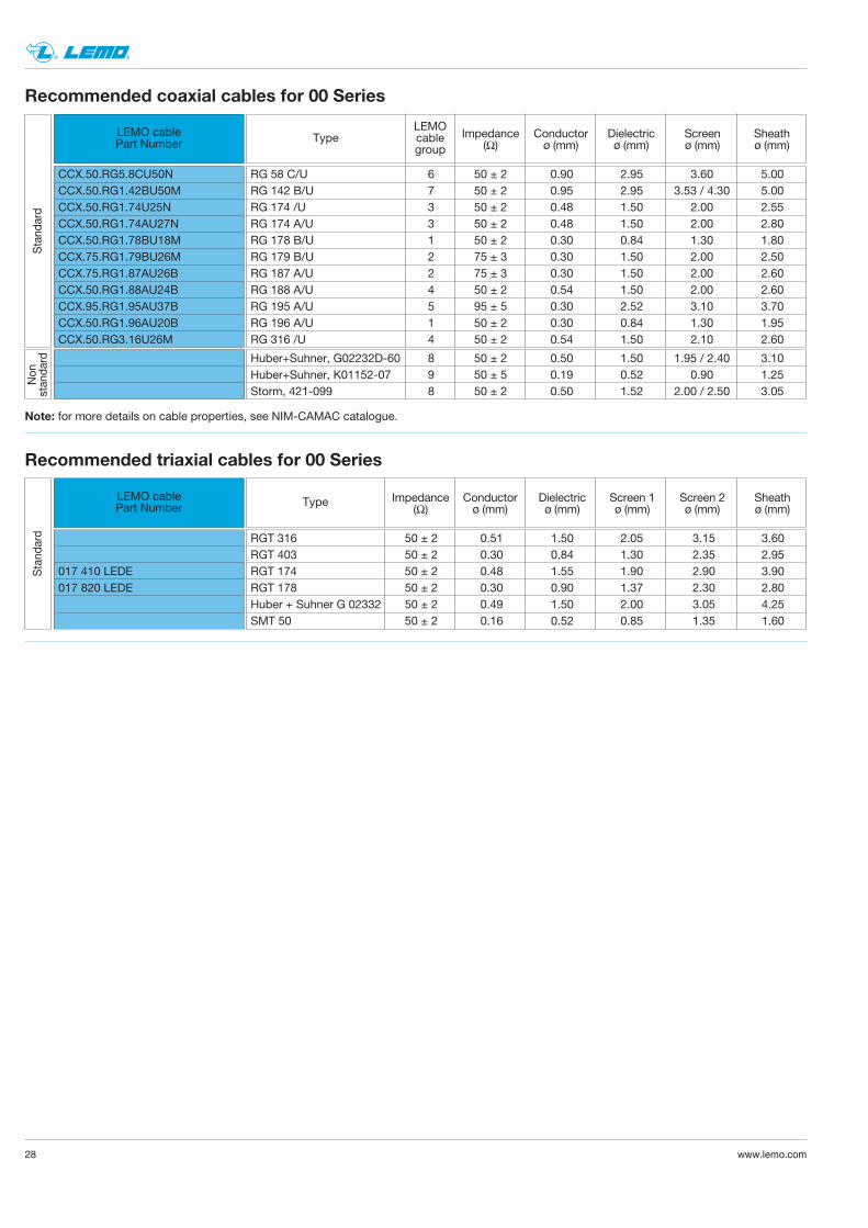
Recommended coaxial cables for 00 Series
LEMO cablePart Number Type
LEMOcablegroup
CCX.50.RG5.8CU50NCCX.50.RG1.42BU50MCCX.50.RG1.74U25NCCX.50.RG1.74AU27NCCX.50.RG1.78BU18MCCX.75.RG1.79BU26MCCX.75.RG1.87AU26BCCX.50.RG1.88AU24BCCX.95.RG1.95AU37BCCX.50.RG1.96AU20BCCX.50.RG3.16U26M
Impedance Conductor Dielectric Screen Sheath(Ω) ø (mm) ø (mm) ø (mm) ø (mm)
RG 58 C/U 6 50 ± 2 0.90 2.95 3.60 5.00RG 142 B/U 7 50 ± 2 0.95 2.95 3.53 / 4.30 5.00RG 174 /U 3 50 ± 2 0.48 1.50 2.00 2.55RG 174 A/U 3 50 ± 2 0.48 1.50 2.00 2.80RG 178 B/U 1 50 ± 2 0.30 0.84 1.30 1.80RG 179 B/U 2 75 ± 3 0.30 1.50 2.00 2.50RG 187 A/U 2 75 ± 3 0.30 1.50 2.00 2.60RG 188 A/U 4 50 ± 2 0.54 1.50 2.00 2.60RG 195 A/U 5 95 ± 5 0.30 2.52 3.10 3.70RG 196 A/U 1 50 ± 2 0.30 0.84 1.30 1.95RG 316 /U 4 50 ± 2 0.54 1.50 2.10 2.60
Non
stan
dard
Stand
ard
Huber+Suhner, G02232D-60 8 50 ± 2 0.50 1.50 1.95 / 2.40 3.10Huber+Suhner, K01152-07 9 50 ± 5 0.19 0.52 0.90 1.25Storm, 421-099 8 50 ± 2 0.50 1.52 2.00 / 2.50 3.05
Note: for more details on cable properties, see NIM-CAMAC catalogue.
Recommended triaxial cables for 00 Series
LEMO cablePart Number
017 410 LEDE017 820 LEDE
Impedance Conductor Dielectric Screen 1 Screen 2 Sheath(Ω) ø (mm) ø (mm) ø (mm) ø (mm) ø (mm)
RGT 316 50 ± 2 0.51 1.50 2.05 3.15 3.60RGT 403 50 ± 2 0.30 0.84 1.30 2.35 2.95RGT 174 50 ± 2 0.48 1.55 1.90 2.90 3.90RGT 178 50 ± 2 0.30 0.90 1.37 2.30 2.80Huber + Suhner G 02332 50 ± 2 0.49 1.50 2.00 3.05 4.25SMT 50 50 ± 2 0.16 0.52 0.85 1.35 1.60
Stand
ard
Type
29www.lemo.com
® ®
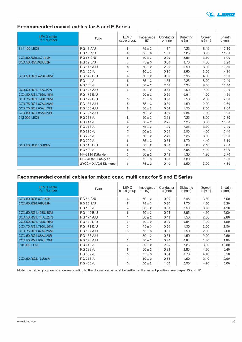
Recommended coaxial cables for mixed coax, multi coax for S and E Series
LEMO cablePart Number
CCX.50.RG5.8CU50NCCX.50.RG5.9BU62N
CCX.50.RG1.42BU50MCCX.50.RG1.74.AU27NCCX.50.RG1.78BU18MCCX.75.RG1.79BU26MCCX.75.RG1.87AU26MCCX.50.RG1.88AU26BCCX.50.RG1.96AU20B213 000 LEDE
CCX.50.RG3.16U26M
LEMO Impedance Conductor Dielectric Screen Sheathcable group (Ω) ø (mm) ø (mm) ø (mm) ø (mm)
RG 58 C/U 6 50 ± 2 0.90 2.95 3.60 5.00RG 59 B/U 5 75 ± 3 0.60 3.70 4.50 6.20RG 122 /U 4 50 ± 2 0.80 2.50 3.20 4.10RG 142 B/U 6 50 ± 2 0.95 2.95 4.30 5.00RG 174 A/U 1 50 ± 2 0.48 1.50 2.00 2.80RG 178 B/U 2 50 ± 2 0.30 0.84 1.30 1.80RG 179 B/U 3 75 ± 3 0.30 1.50 2.00 2.50RG 187 A/U 3 75 ± 3 0.30 1.50 2.00 2.60RG 188 A/U 1 50 ± 2 0.54 1.50 2.00 2.60RG 196 A/U 2 50 ± 2 0.30 0.84 1.30 1.95RG 213 /U 7 50 ± 2 2.25 7.25 8.20 10.30RG 223 /U 6 50 ± 2 0.89 2.95 4.30 5.40RG 302 /U 5 75 ± 3 0.64 3.70 4.40 5.10RG 316 /U 1 50 ± 2 0.54 1.50 2.10 2.60RG 400 /U 5 50 ± 2 1.00 2.98 4.20 5.00
Note: the cable group number corresponding to the chosen cable must be written in the variant position, see pages 15 and 17.
Recommended coaxial cables for S and E Series
LEMO cablePart Number
311 100 LEDE
CCX.50.RG5.8CU50NCCX.50.RG5.9BU62N
CCX.50.RG1.42BU50M
CCX.50.RG1.74AU27NCCX.50.RG1.78BU18MCCX.75.RG1.79BU26MCCX.75.RG1.87AU26MCCX.50.RG1.88AU26BCCX.50.RG1.96AU20B213 000 LEDE
CCX.50.RG3.16U26M
LEMO Impedance Conductor Dielectric Screen Sheathcable group (Ω) ø (mm) ø (mm) ø (mm) ø (mm)
RG 11 A/U 8 75 ± 2 1.17 7.25 8.15 10.10RG 12 A/U 0 75 ± 3 1.20 7.25 8.20 11.80RG 58 C/U 6 50 ± 2 0.90 2.95 3.60 5.00RG 59 B/U 7 75 ± 3 0.60 3.70 4.50 6.20RG 115 A/U 8 50 ± 2 2.25 6.50 8.00 10.50RG 122 /U 4 50 ± 2 0.80 2.50 3.20 4.10RG 142 B/U 6 50 ± 2 0.95 2.95 4.30 5.00RG 144 /U 8 75 ± 3 1.35 7.25 8.00 10.40RG 165 /U 8 50 ± 2 2.46 7.25 8.00 10.40RG 174 A/U 3 50 ± 2 0.48 1.50 2.00 2.80RG 178 B/U 1 50 ± 2 0.30 0.84 1.30 1.80RG 179 B/U 5 75 ± 3 0.30 1.50 2.00 2.50RG 187 A/U 5 75 ± 3 0.30 1.50 2.00 2.60RG 188 A/U 2 50 ± 2 0.54 1.50 2.00 2.60RG 196 A/U 1 50 ± 2 0.30 0.84 1.30 1.95RG 213 /U 8 50 ± 2 2.25 7.25 8.20 10.30RG 214 /U 9 50 ± 2 2.25 7.25 8.80 10.80RG 216 /U 9 75 ± 3 1.20 7.25 8.80 10.80RG 223 /U 7 50 ± 2 0.89 2.95 4.30 5.40RG 225 /U 9 50 ± 2 2.40 7.25 8.80 10.90RG 302 /U 6 75 ± 3 0.64 3.70 4.40 5.10RG 316 B/U 2 50 ± 2 0.60 1.60 2.10 2.80RG 400 /U 6 50 ± 2 1.00 2.98 4.20 5.00HF-2114 Dätwyler 3 50 ± 2 0.48 1.30 1.90 2.70HF-5408/1 Dätwyler 7 75 ± 3 0.60 3.80 5.602YCCY 0.4/2.5 Siemens 6 75 ± 2 0.40 2.50 3.70 4.50
Type
Type
30 www.lemo.com
® ®
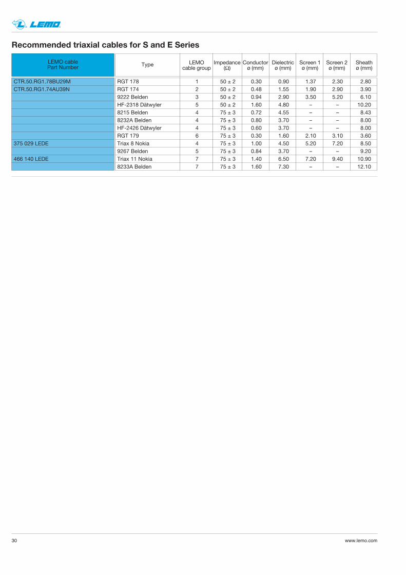
Recommended triaxial cables for S and E Series
LEMO cablePart Number
CTR.50.RG1.78BU29MCTR.50.RG1.74AU39N
375 029 LEDE
466 140 LEDE
LEMO Impedance Conductor Dielectric Screen 1 Screen 2 Sheathcable group (Ω) ø (mm) ø (mm) ø (mm) ø (mm) ø (mm)
RGT 178 1 50 ± 2 0.30 0.90 1.37 2.30 2.80RGT 174 2 50 ± 2 0.48 1.55 1.90 2.90 3.909222 Belden 3 50 ± 2 0.94 2.90 3.50 5.20 6.10HF-2318 Dätwyler 5 50 ± 2 1.60 4.80 – – 10.208215 Belden 4 75 ± 3 0.72 4.55 – – 8.438232A Belden 4 75 ± 3 0.80 3.70 – – 8.00HF-2426 Dätwyler 4 75 ± 3 0.60 3.70 – – 8.00RGT 179 6 75 ± 3 0.30 1.60 2.10 3.10 3.60Triax 8 Nokia 4 75 ± 3 1.00 4.50 5.20 7.20 8.509267 Belden 5 75 ± 3 0.84 3.70 – – 9.20Triax 11 Nokia 7 75 ± 3 1.40 6.50 7.20 9.40 10.908233A Belden 7 75 ± 3 1.60 7.30 – – 12.10
Type
31www.lemo.com
® ®
32 www.lemo.com
® ®
www.lemo.com
® ®
Data subject to change
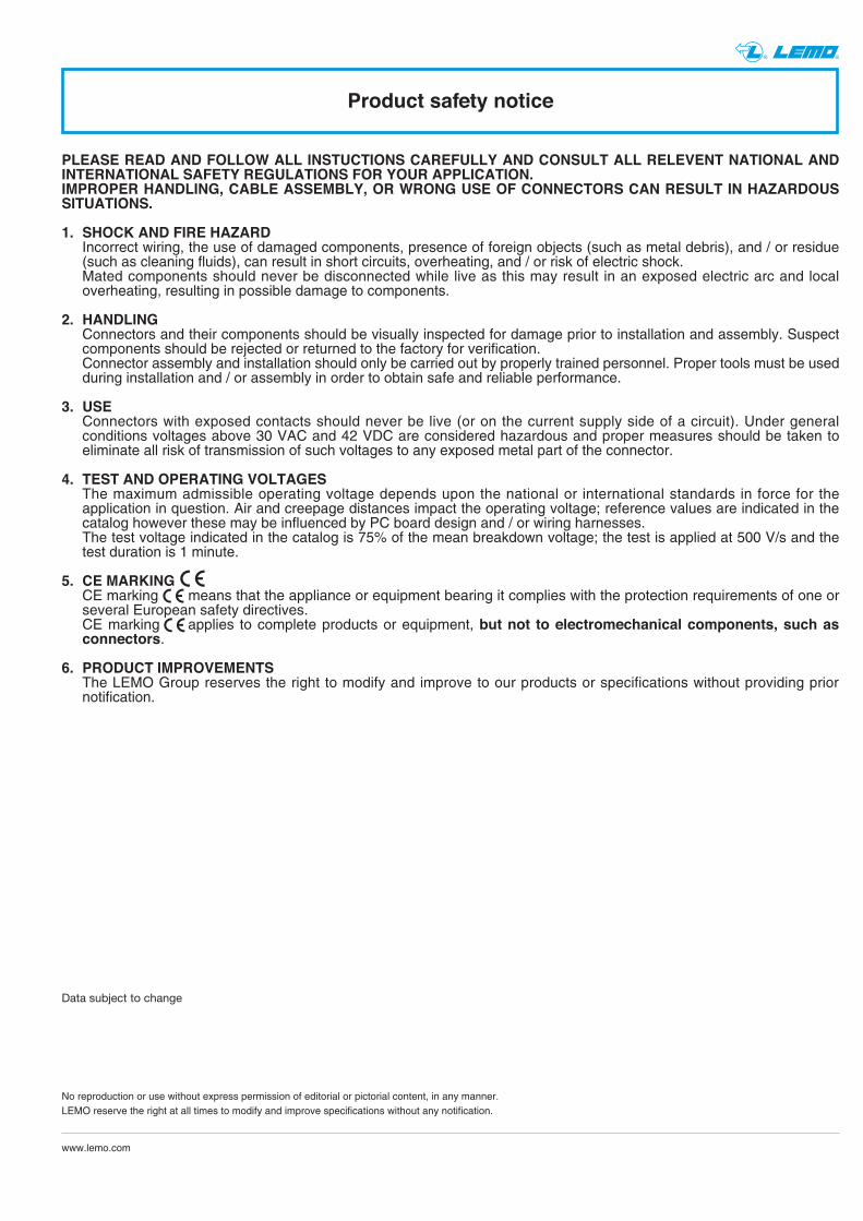
PLEASE READ AND FOLLOW ALL INSTUCTIONS CAREFULLY AND CONSULT ALL RELEVENT NATIONAL ANDINTERNATIONAL SAFETY REGULATIONS FOR YOUR APPLICATION.IMPROPER HANDLING, CABLE ASSEMBLY, OR WRONG USE OF CONNECTORS CAN RESULT IN HAZARDOUSSITUATIONS.
1. SHOCK AND FIRE HAZARDIncorrect wiring, the use of damaged components, presence of foreign objects (such as metal debris), and / or residue (such as cleaning fluids), can result in short circuits, overheating, and / or risk of electric shock.Mated components should never be disconnected while live as this may result in an exposed electric arc and local overheating, resulting in possible damage to components.
2. HANDLINGConnectors and their components should be visually inspected for damage prior to installation and assembly. Suspect components should be rejected or returned to the factory for verification.Connector assembly and installation should only be carried out by properly trained personnel. Proper tools must be usedduring installation and / or assembly in order to obtain safe and reliable performance.
3. USEConnectors with exposed contacts should never be live (or on the current supply side of a circuit). Under general conditions voltages above 30 VAC and 42 VDC are considered hazardous and proper measures should be taken to eliminate all risk of transmission of such voltages to any exposed metal part of the connector.
4. TEST AND OPERATING VOLTAGESThe maximum admissible operating voltage depends upon the national or international standards in force for the application in question. Air and creepage distances impact the operating voltage; reference values are indicated in the catalog however these may be influenced by PC board design and / or wiring harnesses.The test voltage indicated in the catalog is 75% of the mean breakdown voltage; the test is applied at 500 V/s and the test duration is 1 minute.
5. CE MARKINGCE marking means that the appliance or equipment bearing it complies with the protection requirements of one orseveral European safety directives.CE marking applies to complete products or equipment, but not to electromechanical components, such asconnectors.
6. PRODUCT IMPROVEMENTSThe LEMO Group reserves the right to modify and improve to our products or specifications without providing prior notification.
Product safety notice
No reproduction or use without express permission of editorial or pictorial content, in any manner.LEMO reserve the right at all times to modify and improve specifications without any notification.
LEMO HEADQUARTERS
SWITZERLANDLEMO SA Chemin des Champs-Courbes 28 - P.O. Box 194 - CH-1024 EcublensTel. (+41 21) 695 16 00 - Fax (+41 21) 695 16 02 - e-mail: [email protected]
LEMO SUBSIDIARIES
© C
AT
.CT
.LE
N.P
04
10
, p
df
up
da
ted
Ju
ly 2
01
2
LEMO DISTRIBUTORS
AUSTRALIA, BRAZIL, CANADA, CZECH REPUBLIC, GREECE, INDIA, ISRAEL, NEW ZEALAND, PAKISTAN, POLAND, RUSSIA, SOUTH AFRICA, SOUTH KOREA, TAIWAN, TURKEY, UKRAINE
www.lemo.com
AUSTRIALEMO Elektronik GesmbHLemböckgasse 49/E6-31230 WienTel: (+43 1) 914 23 20 0Fax:(+43 1) 914 23 20 [email protected]
CHINALEMO Trading (Shanghai) Co., LtdLEMO Electronics (Shanghai) Co., Ltd 5th Floor, Block 6, City of ELITE,1000 Jinhai Road, PudongShanghai, China 201206Tel: (+86 21) 5899 7721Fax: (+86 21) 5899 [email protected]
DENMARKLEMO Denmark A/SGammel Mosevej 462820 GentofteTel: (+45) 45 20 44 00Fax: (+45) 45 20 44 [email protected]
FRANCELEMO France Sàrl24/28 Avenue Graham BellBâtiment Balthus 4Bussy Saint Georges77607 Marne la Vallée Cedex 3Tel: (+33 1) 60 94 60 94Fax: (+33 1) 60 94 60 [email protected]
GERMANYLEMO Elektronik GmbHHanns-Schwindt-Str. 681829 München Tel: (+49 89) 42 77 03Fax: (+49 89) 420 21 [email protected]
HONG KONGLEMO Hong Kong LtdUnit 1207, 12/F, Corporation Square,8 Lam Lok Street, Kowloon Bay,Kowloon - Hong KongTel: (+852) 2174 0468Fax: (+852) 2174 [email protected]
HUNGARYREDEL Elektronika KftNagysándor József u. 6-121201 BudapestTel: (+36 1) 421 47 10Fax: (+36 1) 421 47 [email protected]
ITALYLEMO Italia srlViale Lunigiana 2520125 MilanoTel: (+39 02) 66 71 10 46Fax: (+39 02) 66 71 10 [email protected]
JAPANLEMO Japan Ltd2-7-22, Mita, Minato-ku, Tokyo, 108-0073Tel: (+81 3) 54 46 55 10Fax: (+81 3) 54 46 55 [email protected]
NETHERLANDS / BELGIUMLEMO Connectors BeneluxDe Trompet 10601967 DA HeemskerkTel. (+31) 251 25 78 20Fax (+31) 251 25 78 [email protected]
NORWAY / ICELANDLEMO Norway A/SStanseveien 6B0975 OsloTel: (+47) 22 91 70 40Fax: (+47) 22 91 70 [email protected]
SINGAPORELEMO Asia Pte Ltd4 Leng Kee Road, #06-09 SiS Building Singapore 159088Tel: (+65) 6476 0672Fax: (+65) 6474 [email protected]
SPAIN / PORTUGALIBERLEMO S.A.Brasil, 45, 08402 GranollersBarcelonaTel: (+34 93) 860 44 20Fax: (+34 93) 879 10 [email protected]
Madrid OfficeAntonio López, 96, 28019 MadridTel: (+34 91) 469 99 19Fax: (+34 91) 469 99 59
SWEDEN / FINLANDLEMO Nordic ABMariehällsvägen 39A 168 65 BrommaTel: (+46 8) 635 60 60Fax: (+46 8) 635 60 [email protected]
SWITZERLANDLEMO Verkauf AGGrundstrasse 22 B6343 RotkreuzTel: (+41 41) 790 49 40Fax: (+41 41) 790 49 [email protected]
UNITED KINGDOMLEMO UK Ltd12-20 North StreetWorthingWest Sussex, BN11 1DUTel: (+44 1903) 23 45 43Fax: (+44 1903) 20 62 [email protected]
USALEMO USA IncP.O. Box 2408Rohnert Park, CA 94927-2408Tel: (+1 707) 578 88 11(+1 800) 444 53 66Fax:(+1 707) 578 08 [email protected]