Coaxial Compound Helicopter for Confined Urban · PDF fileCoaxial Compound Helicopter for...
30
1 Coaxial Compound Helicopter for Confined Urban Operations Wayne Johnson Aeromechanics Office National Aeronautics and Space Administration Ames Research Center, Moffett Field, California Joshua F. Elmore Ernest B. Keen Andrew T. Gallaher Gerardo F. Nunez Aviation Development Directorate – AFDD U.S. Army Research Development, and Engineering Command Redstone Arsenal, Alabama; Hampton, Virginia; Moffett Field, California ABSTRACT A rotorcraft was designed for military operations in a confined urban environment. The specifications included major increases in useful load, range, and speed relative current aircraft capabilities, with a size constraint based on the dimensions of urban streets and intersections. Analysis showed that this combination of requirements is best satisfied by a coaxial main-rotor configuration, with lift compounding to off-load the rotors at high speed, and ducted fans under the rotor disk for propulsion. The baseline design is described, and the aircraft performance is summarized for utility, attack, MEDEVAC, and cargo delivery missions. The impact on size and performance is examined for a number of excursions, including lift-offset main rotors. Technology development required to achieve this advance in capability is recommended. INTRODUCTION . Future military forces must be able to operate in a densely populated urban environment. Military operations in a megacity are complex, dangerous, and intense (Ref. 1). Urban terrain is a great equalizer for operations. The megacity multi-level structures magnify the power of the defender and diminish the attacker’s advantages in firepower and mobility. Urban terrain introduces a unique challenge to aircrews and ground personnel alike with the notion of the urban canyon (Ref. 2). An urban canyon exists when an opponent is shielded by vertical structures. For the aviation community, this means air support at the street-level is needed, including at least an assault and MEDEVAC capability. The street dimensions, hence the . Presented at the AHS Specialists’ Conference on Aeromechanics Design for Vertical Lift, San Francisco, CA, January 20-22, 2016. This is a work of the U.S. Government and is not subject to copyright protection. operational constraints, vary greatly among megacities. Streets in older business sections can range from roughly 8 to 30-ft wide. More developed megacities, with design specifications for streets, may have operating dimensions closer to 60 ft. The size constraints imposed on aircraft that have to fit between buildings along these streets, and also maneuver amongst them, become a critical factor in aircraft designed for operation in the urban environment. A rotorcraft design was developed for military operations in a confined urban environment, using the rotorcraft sizing code NDARC (NASA Design and Analysis of Rotorcraft). This aircraft is the smallest of the family of vertical lift aircraft described in Reference 3. First the paper describes the aircraft specifications, which include major increases in useful load, range, and speed relative current aircraft capabilities, with a size constraint based on the dimensions of urban streets and intersections. The paper shows that this combination of requirements can be best satisfied by a Coaxial Compound Helicopter (CCH):
Transcript of Coaxial Compound Helicopter for Confined Urban · PDF fileCoaxial Compound Helicopter for...

1
Coaxial Compound Helicopter for Confined Urban Operations
Wayne Johnson Aeromechanics Office
National Aeronautics and Space Administration Ames Research Center, Moffett Field, California
Joshua F. Elmore Ernest B. Keen
Andrew T. Gallaher Gerardo F. Nunez
Aviation Development Directorate – AFDD U.S. Army Research Development, and Engineering Command
Redstone Arsenal, Alabama; Hampton, Virginia; Moffett Field, California
ABSTRACT
A rotorcraft was designed for military operations in a confined urban environment. The specifications included major increases in useful load, range, and speed relative current aircraft capabilities, with a size constraint based on the dimensions of urban streets and intersections. Analysis showed that this combination of requirements is best satisfied by a coaxial main-rotor configuration, with lift compounding to off-load the rotors at high speed, and ducted fans under the rotor disk for propulsion. The baseline design is described, and the aircraft performance is summarized for utility, attack, MEDEVAC, and cargo delivery missions. The impact on size and performance is examined for a number of excursions, including lift-offset main rotors. Technology development required to achieve this advance in capability is recommended.
INTRODUCTION. Future military forces must be able to operate in a densely populated urban environment. Military operations in a megacity are complex, dangerous, and intense (Ref. 1). Urban terrain is a great equalizer for operations. The megacity multi-level structures magnify the power of the defender and diminish the attacker’s advantages in firepower and mobility. Urban terrain introduces a unique challenge to aircrews and ground personnel alike with the notion of the urban canyon (Ref. 2). An urban canyon exists when an opponent is shielded by vertical structures. For the aviation community, this means air support at the street-level is needed, including at least an assault and MEDEVAC capability. The street dimensions, hence the .Presented at the AHS Specialists’ Conference on Aeromechanics Design for Vertical Lift, San Francisco, CA, January 20-22, 2016. This is a work of the U.S. Government and is not subject to copyright protection.
operational constraints, vary greatly among megacities. Streets in older business sections can range from roughly 8 to 30-ft wide. More developed megacities, with design specifications for streets, may have operating dimensions closer to 60 ft. The size constraints imposed on aircraft that have to fit between buildings along these streets, and also maneuver amongst them, become a critical factor in aircraft designed for operation in the urban environment.
A rotorcraft design was developed for military operations in a confined urban environment, using the rotorcraft sizing code NDARC (NASA Design and Analysis of Rotorcraft). This aircraft is the smallest of the family of vertical lift aircraft described in Reference 3. First the paper describes the aircraft specifications, which include major increases in useful load, range, and speed relative current aircraft capabilities, with a size constraint based on the dimensions of urban streets and intersections. The paper shows that this combination of requirements can be best satisfied by a Coaxial Compound Helicopter (CCH):

2
a coaxial main-rotor configuration, with lift compounding to off-load the rotors at high speed, and ducted fans under the rotor disk for propulsion (Figure 1). The calibration of NDARC for the CCH performance and weights is described. A baseline aircraft that meets the specifications is presented, including the aircraft performance for utility, attack, MEDEVAC, and cargo delivery missions. The impact on size and performance is examined for a number of excursions, including lift-offset main rotors. Technology maturity and development required to achieve this advance in capability is recommended.
COMPUTATIONAL METHODS
Rotorcraft Sizing Code NDARC NASA Design and Analysis of Rotorcraft (NDARC) is a conceptual/preliminary design and analysis computer program for rapidly sizing and conducting performance analysis of new vehicle concepts with particular emphasis on vertical lift configurations (Refs. 4–7). NDARC has a modular architecture, facilitating its extension to new concepts and the implementation of new computational procedures. NDARC version 1.8f was used in this design activity.
NDARC is an aircraft system tool that performs design and analysis tasks. The design task sizes the vehicle to satisfy a set of design conditions and missions. The analysis tasks include off-design mission analysis and flight performance calculation for point operating conditions. The aircraft size is characterized by parameters such as design gross weight, weight empty, component dimensions, drive system torque limit, fuel tank capacity, and engine power.
To achieve flexibility in configuration modeling, NDARC constructs a vehicle from a set of components, including fuselage, wings, tails, rotors, transmissions, and engines. For efficient program execution, each component uses a surrogate model for performance and weight estimation. Higher fidelity component design and analysis programs as well as databases of existing components provide the information needed to calibrate these surrogate models, including the influence of size and technology level. The reliability of the synthesis and evaluation results depends on the accuracy of the calibrated component models.
The NDARC rotor performance model represents the rotor power as the sum of induced, profile, and parasite terms:
!
P = Pi + Po + Pp . The parasite power (including climb or descent power for the aircraft) is obtained from the wind axis drag force and rotor velocity:
!
Pp = "XV . The induced
power is calculated from the ideal power and the induced power factor
!
" :
!
Pi="P
ideal. The profile power is
calculated from a mean blade drag coefficient:
!
CPo
= (" /8)cd meanFP , where the function
!
FP
accounts for the increase of the blade section velocity with rotor edgewise and axial speed. The induced and profile power cannot be measured separately in a wind tunnel or flight test, only the sum is available from
!
Pi+ P
o= P + XV (if
the rotor wind-axis drag force
!
X is measured or estimated). Therefore analysis is used to separate induced and profile power. In this approach, performance calculations from a comprehensive analysis are correlated with wind tunnel or flight test data; then rotor performance is calculated for the full range of expected flight and operating conditions; finally the parameters of the NDARC rotor performance model are developed based on the calculated
!
" and
!
cd mean
.
NDARC provides default configurations and trim strategies for several common rotary wing configurations, including single main-rotor helicopters, tandem helicopters, coaxial helicopters, and tilt-rotors. In each of these default configurations, trim strategies have been defined, providing a set of starting points for a design study. Here the configuration is a coaxial rotor with fans for auxiliary propulsion. The pilot collective control commands rotor thrust, and pilot cyclic control commands lateral and longitudinal tip-path plane tilt relative the shaft (flapping). Rotor collective and cyclic pitch angles are calculated from thrust and flapping using blade element theory (Refs. 4–5).
For low speed flight, the aircraft is trimmed as usual for a helicopter: net zero force and moment on the aircraft achieved with pilot’s collective stick, cyclic stick, and pedal, and aircraft pitch and roll attitude. For the coaxial configuration, collective stick is mean rotor collective and pedal is differential rotor collective. Cyclic stick goes to both rotors, with no differential cyclic control. For cruise, the aircraft is trimmed as a compound: net zero force and moment on the aircraft achieved with pilot’s collective stick, cyclic stick, and pedal, fan collective, and aircraft roll attitude, for a specified aircraft pitch angle.
Comprehensive Analysis CAMRAD II Performance analyses were conducted with the rotorcraft comprehensive analysis CAMRAD II (Ref. 8). CAMRAD II is an aeromechanics analysis of rotorcraft that incorporates a combination of advanced technologies, including multibody dynamics, nonlinear finite elements, and rotorcraft aerodynamics. The trim task finds the equilibrium solution for a steady state operating condition,

3
and produces the solution for performance, loads, and vibration. The flutter task linearizes the equations about the trim solution, and produces the stability results. The aerodynamic model includes a wake analysis to calculate the rotor nonuniform induced-velocities, using rigid, prescribed, or free wake geometry. CAMRAD II has undergone extensive correlation of performance and loads measurements on rotorcraft (Refs. 9–13).
The CAMRAD II aerodynamic model for the rotor blade is based on lifting-line theory, using steady two-dimensional airfoil characteristics and a vortex wake model. The rotor blade modeling problem of lifting-line theory is unsteady, compressible, viscous flow about an infinite aspect-ratio wing, in a uniform flow consisting of the yawed free stream and the wake-induced velocity. This problem is modeled as two-dimensional, steady, compressible, viscous flow (airfoil tables), plus corrections. The corrections account for swept and yawed flow, spanwise drag, and attached flow unsteady loads. Other corrections available, such as for static stall delay and dynamic stall, were not important for the operating conditions considered here. An incompressible vortex wake is behind the lifting-line, with distorted geometry and rollup. The lifting-line (bound vortex) is at the quarter chord, and the three components of wake-induced velocity are evaluated at collocation points at the three-quarter chord. This model is generally second-order accurate for section lift, which significantly improves the calculation of blade-vortex interaction loading, but less accurate for section moments. The wake analysis calculates the rotor nonuniform induced-velocity using either rigid or free wake geometry. The concentrated tip vortices are the key features of the rotor wake, important for performance, airloads, structural loads, vibration, and noise calculations. The formation of the tip vortices is modeled in CAMRAD II, not calculated from first principles.
Performance calculations for calibration of the NDARC rotor models considered first an isolated rotor, in particular to define profile power including the influence of stall. Then calculations for the coaxial rotor were used to calibrate the rotor-rotor interference effects on induced power. Rotor performance was calculated using nonuniform inflow with rigid wake geometry in high speed cruise and free wake geometry in hover. Airfoil characteristics were obtained from tables representing modern technology airfoils. For calibration of the sizing code performance, the single rotor in cruise was trimmed to a target thrust and flapping trimmed to zero, using rotor collective and cyclic at fixed shaft angle. Hover performance was calculated for a collective sweep.
AIRCRAFT SPECIFICATIONS The design of this aircraft was driven by the need to conduct assault operations within the confines of urban streets and intersections. Review of evolving urban assault and security concepts reveals operation in urban avenues of approach of 12 to 15 m width, and re-orientation in confined spaces of 8 by 12 m (14.4 m inscribed diameter). The helicopter currently performing this role is the MELB (based on MH-6 or MD530F), which has an operating length of 32.6 ft and a width (rotor diameter) of 27.4 ft (9.9 m by 8.4 m). Thus for this investigation, the geometric constraint is 12 by 12 m (39 by 39 ft). Allowing for maneuvering space, the maximum operating dimension (width or length) was thus specified as 32 ft.
Design Mission Figure 2 describes the design mission (urban assault), which is based on insertion/extraction of special operations or fire teams. The payload is 4 passengers of 300 lb each, for a total of 1200 lb. The mission radius is 200 km, with 30 min loiter (without payload) at midpoint. Takeoff (hover out-of-ground-effect) is at 4000 ft altitude and 95ºF (4k/95), midpoint hover is at 6000 ft and 95ºF (6k/95). The aircraft cruises at best range speed Vbr and best altitude, for 75% of the distance (150 km). Penetration speed is at least 200 knots, at 6k/95. This mission requires significant increases in useful load, range, and speed relative current aircraft capabilities.
Small aircraft are particularly sensitive to performance requirements, so these mission specifications, although demanding, are somewhat less stringent than those anticipated for larger aircraft in a family of future military vertical lift aircraft. The vehicle resulting from these specifications can in fact lift 4 x 400 lb passengers. The system needs to be dramatically faster than existing helicopters to be responsive to the demands of the future battlefield. While achieving 230 knots would require significantly greater power, 200 knots is a reasonable compromise between weight and speed. It is assumed that the aircraft can still be transported to the operational region via existing theater assets. Increasing the radius of the design mission would just increase the fuel required and aircraft size.
The reserve fuel is the greater of 30 min or 10% of the mission fuel. Cruise and reserve segments are flown at best range speed Vbr, which is the speed for 99% of maximum specific range (high side). Loiter is at best endurance speed Vbe, which is the speed for minimum fuel flow. The best cruise altitude is determined by lightest

4
weight design, limited by onboard oxygen provisions for un-pressurized aircraft. Oxygen requirements are as follows: 10000 ft altitude and below, no oxygen needed; 10000 to 12000 ft altitude, crew must be on oxygen for durations over one hour, no passenger oxygen needed. Here the cruise mission segment is flown at 10000 ft. The penetration segment is flown at 90% MCP speed or 200 knots, whichever is higher.
Sizing Specifications With the advanced avionics capability anticipated, the aircraft is designed for a single pilot, with no crew chief. With standard mission equipment, the aircraft is capable of being flown without a pilot (OPV). The aircraft is field-configurable as an unmanned system (UAS).
The aircraft must be foldable for rapid transportability (onload, offload, and preparation for flight), hence manual folding and a rotor brake are required. The aircraft must be transportable on the largest vehicle of the future vertical lift family, as well as on a C-17, which constrains the geometry and impacts weight.
The fuel capacity was sized to be 10% greater than the fuel for the design mission, to increase off-design flexibility. The aircraft is capable of air-to-air refueling.
The aircraft cabin is un-pressurized, while the cockpit is designed for slight over-pressure protection against nuclear-biological-chemical threats. Supplemental oxygen provisions are included.
Passenger accommodations are based on 95th percentile person, hence 23-in seat width. Cabin height is 62 in minimum, with no intrusions.
Design gross weight (DGW) is defined at the initial take-off of the sizing mission. Structural design gross weight (SDGW) is defined at the beginning of the penetration segment. Maximum takeoff gross weight (WMTO) is sized by the HOGE capability at 95% MRP and sea level, 103ºF (SL/103).
The transmission is sized by 100% MRP at SL/103, or power for 125% of 6k/95 HOGE weight. The intent of the transmission sizing specification is that the power required for 4k/95 or 6k/95 hover will be useable at SL/103 conditions. If the cruise performance requirement leads to much more installed power than needed for hover (which is the case for a number of the design excursions examined here), the transmission sizing specification is relaxed to 125% of 6k/95 HOGE power.
Equipment Weight and Drag Table 1 defines the mission equipment weights, which were estimated using a functional build-up approach. The communications and displays weights are for the single pilot design. Navigation and pilotage weights reflect an anticipated need for Terrain Following/Terrain Avoidance (TFTA) provisions.
Table 2 defines the systems and equipment weights. The armor corresponds to modern attack rotorcraft level of protection for the pilot, and 4 lb/ft2 cabin armor protection.
Table 3 defines weights of other useful load components. The aircraft serves as primarily an insertion/extraction platform for a four man special operations or fires team, but must have a self-defensive capability against small arms and offensive capability against light-skinned vehicles. Hence a turreted lightweight gun is installed, to reduce the demands on the pilot and to provide more rapid off-axis suppression.
The total drag increment for the equipment is
!
"D /q = 1.38 ft2; composed of 0.5 ft2 for the faired gun, 0.38 ft2 for pilotage and targeting (faired sensor ball), and 0.5 ft2 for aircraft survivability equipment. These drag estimates are based on effective aerodynamic fairings.
AIRCRAFT TYPES CONSIDERED The design specifications combine a maximum operating dimension (hence maximum rotor diameters) of 32 ft, with significant load capability (1960 lb military load, 1200 lb payload, 1100 lb fuel). For these specifications, no closed solution could be found for the single main rotor and tail rotor aircraft type.
A small-wing compound with a single main-rotor was investigated (Figure 3). The configuration includes a wing, propeller, and tail rotor, similar to the AH-56 Cheyenne design. The tail rotor must be outside the main rotor disk, otherwise the moment arm is too small to provide efficient anti-torque. Hence the main rotor radius was significantly less than 32 ft, increasing the disk loading and hover power required. Sizing the tail rotor then further increased the weight and power required. The disk loading was high for both main rotor and tail rotor, hence the solidity was high, and the HOGE takeoff power was large. A converged solution (with a very large tail rotor) was only found at reduced load. The MELB demonstrates that there is a conventional helicopter solution at much reduced lift capability, range, and speed. A small-wing compound that met the geometry (32 ft) and speed (200 knots)

5
specifications only converged with no payload and 20% less range.
There are also solutions if the size constraint is removed. The design mission (load, speed, and range) was met with a main rotor diameter of 32 ft, hence a maximum operating dimension of 38.2 ft. The variability of the width of streets in the world’s most densely populated cities could allow for the aircraft to achieve the desired operational capability by sacrificing a small percentage of accessible locations. However, such an aircraft has a design gross weight of around 11000 lb and a cruise fuel flow of 530 lb/hr, significantly larger than a corresponding coaxial design. Consequently the single main-rotor, small-wing compound configuration was not considered further in this investigation.
A tiltrotor or tiltwing might meet the specifications. Assuming a gross weight of 10000 lb, a wing with a 32-ft span and aspect ratio of 8 has a wing loading of 80 lb/ft2. With a 4-ft wide fuselage and 1-ft clearance, the rotor diameter is 13 ft, and the disk loading of 38 lb/ft2 implies hover power of about 3200 hp. The downwash and outwash resulting from that high disk loading would not be appropriate for operations in urban streets and intersections, therefore these aircraft types were not investigated further for this study.
An aircraft with coaxial main rotors can meet the specifications. With coaxial rotors, a tail rotor is not required for anti-torque and auxiliary propulsion can be placed under the rotor disk, hence the rotor diameter can be set to the maximum operating dimension. Other anti-torque solutions are not considered viable. For example, a rotor with tip drive has unacceptable noise and low thermal efficiency. The following sections describe the coaxial compound helicopter aircraft type.
COAXIAL COMPOUND HELICOPTER (CCH) Figure 1 illustrates the coaxial compound helicopter (CCH) aircraft type. The configuration is compact, the main rotor disks filling the available operating dimensions (32 ft diameter). The height of the coaxial aircraft is an issue for transportability, but the aircraft will fit in the specified transport aircraft. Each rotor has a swashplate (collective and cyclic control), with torque balance provided by differential collective. Fans provide propulsion and augment yaw control. The fans are ducted for efficiency and personnel safety. The airframe, including ducted fans, fits within the footprint of the rotor disk.
The main rotors have modern hub designs with a flap frequency of 1.055/rev. The rotor performance does not rely on lift-offset. For good cruise efficiency, airframe lift is used to off-load the rotors and the fans provide all propulsive force required. Airframe lift comes from the fuselage, hubs, tail, and ducts; a canard is used to generate additional lift. The aircraft has relatively low drag, with faired hubs, retractable gear, and internal payload.
A single engine is used for simplicity and lowest cost. The hover tip speed is 725 ft/sec, the cruise tip speed is 675 ft/sec for advancing tip Mach number of 0.88 at 200 knots. This cruise rotational speed reduction of 93% can be handled by the engine with minimal loss of efficiency, so a single-speed transmission can be used.
Kamov design practices (Refs. 14-17) provide a foundation for this coaxial helicopter, in particular the selection of rotor-rotor vertical spacing (9% rotor diameter), and the rotor hub and control kinematics used to minimize blade flapping magnitude and maximize clearance. Kamov helicopters have been tested well beyond 200 knots, although their cruise speeds are substantially lower.
The computational methods NDARC and CAMRAD II were used to develop the CCH design. Both methods have been used extensively in design and aeromechanics investigations of coaxial rotorcraft (Refs. 11–13).
Aerodynamics and Performance The rotor was sized for
!
CW/" = 0.095, based on design
gross weight and 4k/95 conditions. The comparable blade loading for an advanced helicopter is
!
CW/" = 0.09 ; the
larger value reflects the rotor being off-loaded in cruise.
Airframe lift comes from the fuselage, tail and ducts, hubs and fairings, and the canard. Based on analysis and test of similar configurations, the total airframe lift used is
!
L /q = 35 ft2 at cruise angle of attack, with a corresponding drag due to lift of
!
"D /q = 2.7 ft2. The canard contributes about 15% of this lift. At a dynamic pressure of 100 lb/ft2 (about 200 knots at 6k/95), the airframe lift of 3500 lb unloads the rotor by about 40%.
CAMRAD II calculations were used to calibrate the NDARC rotor performance model. Calculations for an isolated rotor defined basic induced power, and profile power including the influence of stall. Relative to a single main rotor, the coaxial rotor has less induced power at cruise, as well as rotor-rotor interference. Calculations for the coaxial rotor were used to calibrate the rotor-rotor interference effects on induced power. Figure 4 compares

6
the CAMRAD II and NDARC performance calculations, in terms of the rotor equivalent lift-to-drag ratio
!
L /De
= LV /(Pi+ P
o) as a function of flight speed. The
rotors are operating with zero shaft angle (propulsion from the fans) and thrusts of
!
CT/" = 0.076 at 100 knots and
!
CT/" = 0.053 at 200 knots (airframe at constant
!
L /q, so rotor lift decreasing with speed).
The performance model for the fans gave a propulsive efficiency of
!
" =0.80 to 0.82 at cruise.
The hub drag was estimated based on data for good, effective hub fairings:
!
(D /q)hub = 0.5(WMTO /2 /1000)2 / 3.
Weights and Technology The technology level for weight estimation was based on Army aviation S&T technology objectives, with adjustments for unique design features or approaches. Table 4 gives the technology factors used for the major weight groups. These factors were derived by first calibrating the parametric weight equations of NDARC to the closest relevant current technology aircraft (such as UH-60M, AH-64E, RAH-66, V22) or to recent aircraft designs; and then applying corrections to account for advanced technology (particularly materials) and differences in configuration or design.
Vibration reduction weight was estimated, assuming advanced technology approaches, at 1.2% of weight empty.
A contingency weight equal to 5% of weight empty was included to account for uncertainties in the parametric weight estimation methods.
Autorotation Capability With a single engine, the rotor must be designed for adequate autorotation capability. Here the criterion was based on an autorotation index that is the ratio of the rotor kinetic energy and the hover takeoff power (Ref. 18), or
!
AI = KE /P = 12Irotor
"2/P , where
!
Irotor
is the total rotational moment of inertia of the rotor. Power and rotor rotational speed are set by other design criteria, so a specified value of the index was achieved by adding tip mass to the blade, in order to increase blade moment of inertia. The criterion used was
!
AI = 1.5, which corresponds to acceptable autorotation characteristics (Ref. 18). This criterion was based on values of the index for current small helicopters: OH-6
!
AI = 1.53; MD520
!
AI = 1.50 ; MD600
!
AI = 1.02 ; and OH-58D
!
AI = 1.36 . This future aircraft is expected to have automatic recognition of power failure and control to maintain rotor speed, for improved autorotation characteristics.
BASELINE CCH DESIGN Figure 5 illustrates the baseline Coaxial Compound Helicopter designed to meet the specifications of the urban assault mission. Figure 6 shows the aircraft folded, and Figure 7 shows two aircraft as transported by a C-17 or a future large vertical lift aircraft (vehicle E). Figure 8 shows details of the layout, including pilot, passengers, fuel tanks, transmission, and engine.
Design Details Table 5 gives key design details. The design gross weight (DGW = 9416 lb) is defined at the takeoff of the sizing mission. Structural design gross weight (SDGW) is defined at the beginning of the penetration segment. The maximum takeoff gross weight (WMTO = 11672 lb) is sized by the HOGE capability at 95% MRP and SL/103. The weight empty (WE = 6702 lb) is a fixed number of the design, including pilot seat, passenger seats, and armor. The rotor weight is Wrotor = 759 lb. The tip weight (per blade) is required to achieve the specified autorotation index
!
AI . The solidity is twice the single rotor value. The disk loading is based on the area of one rotor.
The takeoff power is single engine SLS IRP (2382 hp). The transmission limit is a torque limit, expressed as power at hover rotor speed. The transmission is sized by 100% MRP at SL/103. The dash speed (200 knots) is for the penetration segment weight, 95% MCP, 6k/95. The power is sized by this speed requirement; hover power gives a fallout speed of 190–195 knots. The drag increment for the equipment (
!
"D /q = 1.38 ft2) increases the design gross weight by 5%, increases power by 10%. The long range cruise speed is 161 knots. Maximum speed (204 knots) is at design gross weight, 100% MCP, 6k/95.
The fuel burn is for the design mission, which has a duration of about 1.5 hr, hence reserve fuel is about 25%. The fuel tank capacity (1096 lb, 164 gallons) is sized to be 10% greater than the mission fuel. The cruise fuel flow (384 lb/hr) is a measure of efficiency. The aircraft equivalent lift-to-drag ratio is
!
L /De
=WV /P , and the aircraft figure of merit is based on gross weight and total power. The rotor equivalent lift-to-drag ratio is
!
L /De
=
!
LV /(Pi+ P
o) , and the rotor figure of merit is based on
rotor thrust and rotor power.
For design excursions, aircraft purchase price increments relative this baseline design are presented. The cost was estimated using the CTM model (Ref. 19), which has an accuracy of about 20% for airframe cost.

7
Table 6 presents rotor, fan, lifting surface, and engine parameters of the design. The engine model is a generic advanced technology engine, scaled from a nominal size of 3000 hp. Table 7 gives the drag buildup for the basic aircraft in cruise (landing gear retracted), which is a clean design for a rotorcraft (
!
D /q = 1.39(W /1000)2 / 3 ). The
equipment drag increment is 1.38 ft2. Then with 2.7 ft2 drag due to lift, the total drag is
!
D /q =11.2 ft2.
Table 8 gives the weight empty details for the baseline CCH design.
Figure 9 compares the operating dimensions and cabin of the CCH and the MD500/530 (MELB). The CCH rotor diameter is 32 ft, while the MD500/530 rotor diameter is 27.4 ft. The length of the MD500 is 31 ft; the length of the MD530 is 32.6 ft. The disk loading is 8 lb/ft2 for the MELB (4700 lb gross weight) and 5.25 lb/ft2 for the MD530 (3100 lb), compared to 11.7 lb/ft2 for the CCH.
Performance Figure 10 shows the payload-radius for the urban assault mission. The takeoff weight at the fuel-tank corner is determined by the 6k/95 midpoint hover. The cruise segment is flown at 10000 ft. The aircraft power is sized by the 200 knot dash speed requirement. Using that power for hover gives more lift than is required for the design mission. Hence the payload capability is above the 1200 lb specification. At 200 km radius, the aircraft is capable of lifting four 400-lb passengers (1600 lb total). The fuel tank is sized 10% larger than the design mission fuel, hence the radius capability is above the 200 km required for the design mission. Also shown in Figure 10 is the lift capability (1616 lb) at the 120 nm (222 km) radius required for the Special Operations Command (SOCOM) urban assault concept of employment.
The best effort speeds as a function of altitude are shown in Figure 11, at design gross weight and ISA conditions. Here VMCP is the speed using 100% MCP. The peak speed is 218 knots, at 4000-6000 ft ISA. Table 5 gives a maximum speed of 204 knots, at 100% MCP, design gross weight, and 6k/95 conditions. Table 5 also gives the dash speed of 200 knots, which is at 95% MCP, penetration weight, 6k/95.
Figure 12 shows the aircraft hover (HOGE at 100% MRP) lift capability (payload plus fuel) as a function of altitude. The aircraft gross weight is the sum of operating weight, payload, and fuel. For these calculations the operating weight is 7260 lb, which equals the empty weight (6702 lb) plus 558 lb of fixed useful load. The hot day
atmosphere has a temperature of 103ºF at sea level, and 91.5ºF at 3000 ft.
The performance of the CCH is compared with that of the MD530F in Figure 13. The mission is conducted entirely at 4k/95 for the CCH (takeoff, cruise, midpoint landing) and at 5k/ISA for the MD530F. Compared to the MD530F, the CCH offers 1500 lb more lift capability, 40% more range, and 30% shorter response times.
Mission Capability In addition to the urban assault role, the CCH is capable of performing light attack, cargo, counter-IADS, and MEDVAC missions. Table 9 lists the payload, equipment and useful load increments, and drag increments for these missions. Table 10 gives the aircraft weight at takeoff.
Light Attack Mission Figure 14 describes the light attack mission. The payload consists of 2 JAGM, 14 rockets, and 6000 rounds 7.62 mm, for total weight of 1020 lb. The payload is expended during the midpoint loiter. The mission radius is 200 km, with 15 min HOGE and 15 min loiter at midpoint. Takeoff HOGE is at 4k/95, midpoint hover is at 6k/95. The aircraft cruises at best range speed Vbr and best altitude (10000 ft) for 75% of the distance (150 km). Penetration speed is at least 200 knots, at 6k/95.
The CCH in light attack configuration is shown in Figure 15. The weapons are carried internally, which requires a wider door than for the urban assault mission. Figure 16 shows the payload-radius. The lift capability at 200 km radius is sufficient to carry two additional JAGM.
UAS Conversion The aircraft is designed to be field-configurable as an unmanned system. The baseline aircraft is optionally-piloted without re-configuration. The UAS conversion removes equipment and load totaling 594 lb: pilot (250 lb), crashworthy/ armored pilot seat (160.4 lb), cockpit controls (20 lb), cabin armor (68.4 lb), passenger seats (80 lb), and survival kit (15 lb). The desired ranges require more fuel than in the standard tanks (1096 lb), so a 788 lb (118 gal, 15.7 ft3) auxiliary fuel tank is added in the cockpit. The UAS kit adds 137 lb: additional electronics (50 lb), and the auxiliary fuel tank (86.7 lb).
Cargo UAS Mission Figure 17 describes the cargo UAS mission. The payload is 1200 lb, carried in the cabin. The payload is dropped at the midpoint. The mission radius is 424 km, with 5 min loiter at midpoint. Takeoff HOGE is at SL/103, midpoint

8
hover is at 6k/95. The aircraft cruises at best range speed Vbr and best altitude (10000 ft) for the entire radius.
The CCH in cargo UAS configuration is shown in Figure 18. Figure 19 shows the payload-radius. The performance of the CCH cargo UAS is compared with that of the KMAX in Figure 20, for missions conducted entirely at 4k/95 (takeoff, cruise, midpoint landing). For CCH performance with external load, 50 ft2 additional drag was assumed. Payloads up to 2500 lb covered 65% of KMAX deliveries during operations in Afghanistan. At that payload, the CCH offers significantly greater radius capability.
Counter-IADS UAS Mission Figure 21 describes the counter-IADS (Integrated Air Defense System) mission. The payload is two AGM-88E HARMs (1600 lb). The mission radius is 424 km, with the payload expended at midpoint. Takeoff HOGE is at SL/103. The aircraft cruises at best range speed Vbr and best altitude (10000 ft) for 75% of the distance (318 km). Penetration speed is at least 200 knots, at 6k/95.
Figure 22 shows the CCH counter-IADS UAS configuration. The HARMs are carried externally, which increases the drag by 6 ft2. Figure 23 shows the payload-radius.
MEDEVAC Mission Figure 24 describes the MEDEVAC mission. The payload consists of a critical care team (500 lb), litter (25 lb), and medical kits (100 lb) for a total of 625 lb on the ingress segment; plus one 335-lb patient returning for a total of 960 lb. The mission radius is 200 km, with 10 min loiter at midpoint. Takeoff HOGE is at 4k/95, midpoint hover is at 6k/95. The aircraft cruises at maximum continuous power speed and best altitude (10000 ft) for the entire radius.
Figure 25 shows the MEDEVAC configuration. The payload-radius is shown in Figure 26. The aircraft is capable of a 230 km radius.
Deployment The CCH can be carried in a mission-ready configuration by a large transport aircraft, or the CCH can self-deploy in a UAS configuration. The desired capability is 2100 nm range with headwinds, 10% fuel reserve, and takeoff and landing at SL/103. With a single engine and long duration (about 17 hours), this mission is best done without a pilot. In order to account for the self-deploy capability, the drive limit was increased to 2350 hp (for more lift) and the fuselage weight increased by 100 lb (for external tank
installation and structure); the result was an increase in weight empty by 215 lb. The aircraft was flown in OPV configuration, without the pilot, gun, ammunition, and passenger seats. For the 2100 nm mission (zero payload), the (rolling) takeoff weight is 18200 lb, which is 1.9 times the structural design gross weight. The takeoff fuel required is 9976 lb, using a 3000-lb cabin auxiliary tank and a 5831-lb external auxiliary tank (drag increment 1.8 ft2). The block time is 17 hours, and the block speed is 124 knots. Figure 27 shows the zero-wind payload-range for this configuration.
For rapid operational deployment, a more practical configuration is the piloted aircraft with a 3000-lb internal cabin auxiliary fuel tank. The aircraft is configured as mission-ready, only requiring removal of the cabin auxiliary tank. Figures 28 and 29 show the payload-range and response time, flying at best range speed and maximum speed, respectively. Takeoff is at maximum HOGE weight, SL/103. Cruise is at 6000 to 10000 ft. With only standard fuel tanks, the zero-payload range is 300–340 nm. With the auxiliary fuel tank, flying at best range speed, the zero-payload range is over 1400 nm, with a block speed of 166 knots. For maximum speed (100% MCP), the zero-payload range is almost 1300 nm, with a block speed of 192 knots.
DESIGN EXCURSIONS A number of design excursions were examined, to identify the impact of specification changes and to explore the robustness of the CCH configuration to design changes. Key aircraft size and performance parameters are compared to the baseline design, following the format of Table 5.
Twin Engines Table 11 shows the impact of designing the aircraft with twin engines. With two engines, the rotor moment of inertia is determined by the blade inertia; adding weight in order to meet the autorotation requirement is not necessary. However the two engines are individually less efficient than a single engine. The resulting twin engine design is about the same size as the single engine design. Historical data for airframe cost shows a significant reduction for single engine, compared to multiple engines. The CTM cost model (Ref. 19) has a factor of 0.736 for single engine, relative to multi-engine, probably reflecting general aircraft complexity as well as simply the number of engines. The cost of a twin-engine design is estimated at 8–10% greater than that of a single-engine design.
9
Hence the cost increase of the twin-engine design is about $1.1M.
Also shown in Table 11 is the result if the autorotation requirement is not used. Meeting the autorotation index (AI) specification requires 13.0 lb per blade, a total of 104 lb tip weight, increasing the weight empty by almost 300 lb.
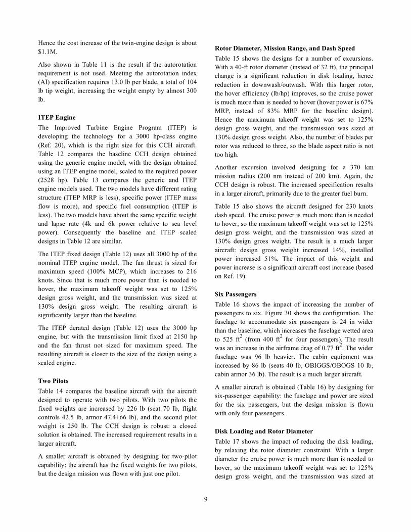
ITEP Engine The Improved Turbine Engine Program (ITEP) is developing the technology for a 3000 hp-class engine (Ref. 20), which is the right size for this CCH aircraft. Table 12 compares the baseline CCH design obtained using the generic engine model, with the design obtained using an ITEP engine model, scaled to the required power (2528 hp). Table 13 compares the generic and ITEP engine models used. The two models have different rating structure (ITEP MRP is less), specific power (ITEP mass flow is more), and specific fuel consumption (ITEP is less). The two models have about the same specific weight and lapse rate (4k and 6k power relative to sea level power). Consequently the baseline and ITEP scaled designs in Table 12 are similar.
The ITEP fixed design (Table 12) uses all 3000 hp of the nominal ITEP engine model. The fan thrust is sized for maximum speed (100% MCP), which increases to 216 knots. Since that is much more power than is needed to hover, the maximum takeoff weight was set to 125% design gross weight, and the transmission was sized at 130% design gross weight. The resulting aircraft is significantly larger than the baseline.
The ITEP derated design (Table 12) uses the 3000 hp engine, but with the transmission limit fixed at 2150 hp and the fan thrust not sized for maximum speed. The resulting aircraft is closer to the size of the design using a scaled engine.
Two Pilots Table 14 compares the baseline aircraft with the aircraft designed to operate with two pilots. With two pilots the fixed weights are increased by 226 lb (seat 70 lb, flight controls 42.5 lb, armor 47.4+66 lb), and the second pilot weight is 250 lb. The CCH design is robust: a closed solution is obtained. The increased requirement results in a larger aircraft.
A smaller aircraft is obtained by designing for two-pilot capability: the aircraft has the fixed weights for two pilots, but the design mission was flown with just one pilot.
Rotor Diameter, Mission Range, and Dash Speed Table 15 shows the designs for a number of excursions. With a 40-ft rotor diameter (instead of 32 ft), the principal change is a significant reduction in disk loading, hence reduction in downwash/outwash. With this larger rotor, the hover efficiency (lb/hp) improves, so the cruise power is much more than is needed to hover (hover power is 67% MRP, instead of 83% MRP for the baseline design). Hence the maximum takeoff weight was set to 125% design gross weight, and the transmission was sized at 130% design gross weight. Also, the number of blades per rotor was reduced to three, so the blade aspect ratio is not too high.
Another excursion involved designing for a 370 km mission radius (200 nm instead of 200 km). Again, the CCH design is robust. The increased specification results in a larger aircraft, primarily due to the greater fuel burn.
Table 15 also shows the aircraft designed for 230 knots dash speed. The cruise power is much more than is needed to hover, so the maximum takeoff weight was set to 125% design gross weight, and the transmission was sized at 130% design gross weight. The result is a much larger aircraft: design gross weight increased 14%, installed power increased 51%. The impact of this weight and power increase is a significant aircraft cost increase (based on Ref. 19).
Six Passengers Table 16 shows the impact of increasing the number of passengers to six. Figure 30 shows the configuration. The fuselage to accommodate six passengers is 24 in wider than the baseline, which increases the fuselage wetted area to 525 ft2 (from 400 ft2 for four passengers). The result was an increase in the airframe drag of 0.77 ft2. The wider fuselage was 96 lb heavier. The cabin equipment was increased by 86 lb (seats 40 lb, OBIGGS/OBOGS 10 lb, cabin armor 36 lb). The result is a much larger aircraft.
A smaller aircraft is obtained (Table 16) by designing for six-passenger capability: the fuselage and power are sized for the six passengers, but the design mission is flown with only four passengers.
Disk Loading and Rotor Diameter Table 17 shows the impact of reducing the disk loading, by relaxing the rotor diameter constraint. With a larger diameter the cruise power is much more than is needed to hover, so the maximum takeoff weight was set to 125% design gross weight, and the transmission was sized at

10
130% design gross weight. Also, the number of blades per rotor was reduced to three.
With a 39.5-ft diameter rotor, the disk loading matches that of the UH-60 Blackhawk: UH-60M maximum takeoff weight (internal load) of 22000 lb gives a disk loading of 9.73 lb/ft2.
Table 18 shows a disk loading sweep for an aircraft design using the ITEP engine (derated, transmission limit 2150 hp and fan thrust sized for 200 knots), with capability for two pilots and six passengers (design mission flown with one pilot and four passengers). Flying the design mission with two pilots and six passengers resulted in a vehicle weight of about 11700 lb. With a 41.5 ft diameter rotor, the disk loading matches that of the UH-60 Blackhawk.
Figure 31 summarizes the variation of the design gross weight with rotor diameter for the baseline configuration, and for the aircraft with ITEP engine, two pilots, and six passengers. Lines of constant disk loading are shown; based on design gross weight, the UH-60 disk loading is 7.8 lb/ft2. The design gross weight does not vary much with disk loading because the installed power was sized by the cruise conditions, and because the maximum takeoff weight and transmission limit were based on the installed power only for the 32-ft diameter designs.
Since the aircraft power was determined by the cruise condition, the principal impact of disk loading is on the outwash characteristics. The Paxman force (Ref. 21) is a measure of the action of the rotorcraft outwash on a person, which depends on the height and shape of the outwash velocity field, as well on the velocity magnitude (which follows from the disk loading). Figure 31 shows a line for constant Paxman force, equivalent to the UH-60 value. Since the CCH aircraft is smaller than the UH-60, the CCH produces the same force at higher disk loading. The baseline design at 32-ft diameter produces less force than a UH-60, even though the disk loading is almost 12 lb/ft2. The larger aircraft (ITEP engine, two pilots, six passengers) produces that same force as from a UH-60 at 34.5-ft diameter. Thus with a criterion based on personnel operating in the outwash field, the higher disk loading of the aircraft constrained by the urban operations should be acceptable.
If the size constraint based on the dimensions of urban streets and intersections is eliminated entirely, then other rotorcraft configurations become viable candidates, notably a small-wing compound helicopter with a single main rotor.
LIFT OFFSET ROTORS A lift-offset rotor is a hingeless rotor that can attain good efficiency at high speed, by operating with more lift on the advancing side than on the retreating side of the rotor disk (Refs. 11–12). By operating a rotor in edgewise flight with lift offset, attaining good performance at high forward speed is possible. A conventional rotor with an articulated hub is constrained to operate with small hub moments. In forward flight, the retreating side of the disk is not able to generate much lift because of low dynamic pressure and stall, so for roll moment balance the advancing side is not allowed to generate much lift either. The resulting load distribution over the rotor disk is far from optimum for either induced or profile power losses, and the rotor efficiency and lift capability steadily decrease with forward speed. Even hingeless and bearingless rotors are generally not designed for the blades and hubs to carry significant roll moment, and thus encounter similar aerodynamic performance limitations. However, a very stiff hingeless rotor can be designed that will permit operation with significant roll moment, typically with rotor lift offsets of 20%. Roll moment balance of the entire aircraft requires either twin main rotors or perhaps a wing. The lift offset concept was demonstrated for the coaxial configuration (Advancing Blade Concept) by the XH-59A flight demonstration program of the 1970s (Ref. 22). While confirming the basic viability of the concept, the aerodynamic performance of the XH-59A was compromised by the choice of airfoils, planform, and twist, as well as by high hub drag. In addition, the stiff hingeless rotors led to a heavy hub design and high vibration in flight. Recently the capability of lift-offset rotors has been re-examined, including the impact of current and advanced technology (Refs. 23–24).
By carrying a significant roll moment, the rotor profile power and induced power can be greatly reduced in high speed edgewise flight. CAMRAD II calculations were used to calibrate the NDARC rotor performance model. Figure 32 compares the CAMRAD II and NDARC performance calculations, in terms of rotor equivalent lift-to-drag ratio as a function of flight speed. The rotors are operating with zero shaft angle and a lift offset of 0.25R.
Taking advantage of the better lift capability, the lift-offset rotor was sized for
!
CW/" = 0.116 , based on design gross
weight and 4k/95 conditions. Considering the larger frontal area of the hingeless rotors, the hub drag was estimated using
!
(D /q)hub = 0.597(WMTO /2 /1000)2 / 3 .
Vibration reduction weight was estimated at 2.6% of weight empty.

11
Table 19 compares the baseline CCH and lift-offset compound (LOC) designs. The lift-offset rotor has better performance from less blade area. Primarily because of the higher rotor weight (needed to carry the hub roll moments), the aircraft weight empty, power, fuel burn, and cost are higher for the LOC. These results are consistent with lift-offset designs for other missions and larger aircraft.
RECOMMENDED TECHNOLOGY MATURATION The Coaxial Compound Helicopter designs presented here are based on estimates of component weights and performance. The performance can be verified first by wind tunnel tests and then by flight tests of the configuration. Such tests would also provide substantiation of the structural loads, from which detailed designs can be made to confirm the weights.
The impact of aerodynamic interference on the aircraft handling qualities, loads, and performance must be established through test and calculations, and design solutions found for any problems encountered. While that statement is true of any rotorcraft, the CCH configuration with coaxial rotors, canard and tail plane, fans and ducts has more possibilities for interference issues. Exploring and solving the interactional aerodynamic phenomena of the CCH before (instead of during) the flight test is recommended.
Taking the coaxial configuration to high speed may be expected to introduce interesting dynamics phenomena. The blade tip clearance must be maintained in all conditions, particularly in high speed or high load maneuvers. Tip-path-plane control should be developed (including flight test), using sensing of the blade flap motion, fed back to blade pitch control, either in the rotating or non-rotating frame.
With a single engine, the rotor must be designed for adequate autorotation capability. Specifically, acceptable autorotation characteristics are achieved by adding tip weights in order to increase the rotor rotational inertia. For improved autorotation characteristics, automatic recognition of power failure and control to maintain rotor speed should be developed for this aircraft. Perhaps the improvements achieved with control will permit reduced rotor weight.
SUMMARY AND CONCLUSIONS NDARC was used to define a rotorcraft design for military operations in a confined urban environment. Table 20 summarizes the baseline specifications and resulting
fallout capability. The specifications included major increases in useful load, range, and speed compared to current aircraft capabilities, with a 32-ft operating size constraint based on the dimensions of urban streets and intersections. Analysis showed that this combination of specifications is best satisfied by a coaxial main-rotor configuration, with lift compounding to off-load the rotors at high speed, and ducted fans under the rotor disk for propulsion.
The baseline specifications are met by a Coaxial Compound Helicopter (CCH) with a design gross weight of 9400 lb and installed takeoff power of 2400 hp. The aircraft power is sized by the 200 knot dash speed specification. Using that power for hover gives more lift than is required for the design mission. Hence the payload capability is above the 1200 lb specification. At 200 km radius, the aircraft is capable of lifting four 400 lb passengers (1600 lb total). The fuel tank is sized 10% larger than the design mission fuel, hence the radius capability is above the 200 km required for the design mission.
The baseline CCH design is robust, so while increasing a requirement resulted in a larger aircraft, a closed design solution was still obtained. Table 20 summarizes the results of several design excursions, in terms of weight and power increases. Extending the mission radius to 370 km increased the weight by 700 lb. Accommodating six passengers added up to 1400 lb and 375 hp. Two-pilot operation increased the weight by up to 700 lb. Increasing the design speed to 230 knots added 1335 lb and 1200 hp. Using a derated ITEP engine added at least 250 lb, but a new engine development program would not then be required. A twin-engine design added about 200 lb, and at least $1M in purchase cost. An aircraft could be designed with even greater capability than these examples, at the cost of additional weight and power.
The baseline specifications represent a good balance of capability. The CCH meets these specifications at a practical weight and power, with good operational suitability. The technology maturation and development needed to achieve this capability includes work on interactional aerodynamics of the configuration and the dynamics of high-speed coaxial rotors.
REFERENCES 1) United States Army. “The Megacity: Operational Challenges For Force 2025 And Beyond.” Army Capabilities Integration Center, Report HD-228176, August 2014.

12
2) United States Army. “The Infantry Battalion.” Field Manual 3-21.20, December 2006.
3) Keen, E.B., and Tenney, B.S. “Keen, E.B., and Tenney, B.S.” AHS Specialists’ Conference on Aeromechanics Design for Vertical Lift, San Francisco, CA, January 2016.
4) Johnson, W. “NDARC. NASA Design and Analysis of Rotorcraft.” NASA TP 2015-218751, April 2015.
5) Johnson, W. “NDARC — NASA Design and Analysis of Rotorcraft. Theoretical Basis and Architecture.” American Helicopter Society Specialists’ Conference on Aeromechanics, San Francisco, CA, January 2010.
6) Johnson, W. “NDARC — NASA Design and Analysis of Rotorcraft. Validation and Demonstration.” American Helicopter Society Specialists’ Conference on Aeromechanics, San Francisco, CA, January 2010.
7) Johnson, W. “Propulsion System Models for Rotorcraft Conceptual Design.” Fifth Decennial AHS Aeromechanics Specialists’ Conference, San Francisco, CA, January 22-24, 2014.
8) Johnson, W., “Technology Drivers in the Development of CAMRAD II,” American Helicopter Society Aeromechanics Specialist Meeting, San Francisco, California, January 1994.
9) Johnson, W. “Rotorcraft Aeromechanics Applications of a Comprehensive Analysis.” HeliJapan 1998: AHS International Meeting on Rotorcraft Technology and Disaster Relief, Gifu, Japan, April 1998.
10) Yeo, H., Bousman, W. G., and Johnson, W., “Performance Analysis of a Utility Helicopter with Standard and Advanced Rotor,” Journal of the American Helicopter Society, Vol. 49, No. 3 (July 2004).
11) Johnson, W. “Influence of Lift Offset on Rotorcraft Performance.” NASA TP 2009-215404, November 2009.
12) Johnson, W.; Moodie, A.M.; and Yeo, H. “Design and Performance of Lift-Offset Rotorcraft for Short-Haul Missions.” American Helicopter Society Future Vertical Lift Aircraft Design Conference, San Francisco, CA, January 2012.
13) Yeo, H., and Johnson, W. “Prediction of Maximum Lift Capability of Helicopter Rotors.” Journal of Aircraft, Vol. 52, No. 1, (January-February 2015).
14) Kasjanikov, V.A. “Coaxial Helicopters — Current Status and Future Developments.” Vertiflite, Vol. 36, No. 5 (September/October 1990).
15) Bourtsev, B.N., and Selemenev, S.V. “Blade Flap Motion and Lower-to-Upper Rotor Blade Tips Clearances of Coaxial Helicopters.” Journal of the American Helicopter Society, Vol. 41, No. 1 (January 1996).
16) Bourtsev, B.N.; Selemenev, S.V.; and Vagis, V.P. “Coaxial Helicopter Rotor Design and Aeromechanics.” Twenty-Fifth European Rotorcraft Forum, Rome, Italy, September 1999.
17) Mikheyev, S.V.; Bourtsev, B.N.; Danilkina, V.L.; Ivannikova, R.V.; Selemenev, S.V.; and Schetinin, Y.S. “Kamov Composite Blades.” Thirty-First European Rotorcraft Forum, Florence, Italy, September 2005.
18) Wood, T.L. “High Energy Rotor System.” American Helicopter Society 32nd Annual National V/STOL Forum, Washington, D.C., May 1976.
19) Harris, F.D., and Scully, M.P. “Rotorcraft Cost Too Much.” Journal of the American Helicopter Society, Vol. 43, No. 1, January 1998.
20) United States Army. "Army Equipment Program in Support of President's Budget 2016." Office of the Deputy Chief of Staff, G-8 Future Force Division, April 2015.
21) Silva, M.J., and Riser, R. “CH-47D Tandem Rotor Outwash Survey.” American Helicopter Society 67th Annual Forum, Virginia Beach, VA, May 2011.
22) Ruddell, A.J., and Macrino, J.A. “Advancing Blade Concept (ABC) High Speed Development.” American Helicopter Society 36th Annual Forum, Washington, D.C., May 1980.
23) Bagai, A. “Aerodynamic Design of the X2 Technology DemonstratorTM.” American Helicopter Society 64th Annual Forum, Montreal, Canada, April 2008.
24) Walsh, D.; Weiner, S.; Arifian, K.; Lawrence, T.; Wilson, M.; Millott, W.; and Blackwell, R. “High Airspeed Testing of the Sikorsky X2 TechnologyTM Demonstrator.” American Helicopter Society 67th Annual Forum, Virginia Beach, VA, May 2011.
NOMENCLATURE
Acronyms and Subscripts CAMRADII Comprehensive Analytical Model of
Rotorcraft Aerodynamics and Dynamics CCH Coaxial Compound Helicopter DGW design gross weight HOGE hover out of ground effect IADS Integrated Air Defense Systems

13
IRP intermediate rated power ISA International Standard Atmosphere ITEP Improved Turbine Engine Program LOC lift-offset compound MEDEVAC medical evacuation MELB mission-enhanced little bird MCP maximum continuous power MRP maximum rated power NDARC NASA Design and Analysis of Rotorcraft OPV optionally-piloted vehicle sfc specific fuel consumption SDGW structural design gross weight SLS sea level standard UAS unmanned aerial system WE weight empty WMTO maximum takeoff weight
Symbols
!
A rotor disk area,
!
"R2
!
AI autorotation index
!
cd mean
mean drag,
!
CPo
= (" /8)cd meanFP
!
CPo
profile power coefficient,
!
Po/"AVtip
3
!
CW
weight coefficient,
!
W /"AVtip2
!
CT
rotor thrust coefficient,
!
T /"AVtip2
!
D drag
!
FP
profile power speed factor
!
FM hover figure of merit
!
Irotor
rotor rotational inertia
!
L lift; rotor wind-axis lift
!
L /De equivalent lift-to-drag ratio,
!
LV /(Pi+ P
o) for
rotor,
!
WV /P for aircraft
!
P rotor power
!
Pi rotor induced power
!
Pideal
rotor ideal induced power
!
Po rotor profile power
!
Pp rotor parasite power,
!
"XV
!
q dynamic pressure,
!
12"V 2
!
Q drive train torque
!
R rotor blade radius
!
T rotor thrust
!
V flight speed
!
Vbr
best range speed (99% high side)
!
Vbe
best endurance speed
!
VMCP
max continuous power speed
!
Vtip rotor tip speed,
!
"R
!
W weight
!
X rotor wind-axis drag
!
" induced power factor,
!
Pi="P
ideal
!
" air density
!
" rotor rotational speed
Operating Condition 4k/95 4000 ft altitude, 95ºF 6k/95 6000 ft altitude, 95ºF 10k/ISA 10000 ft altitude, standard temperature SL/103 sea level, 103ºF
Table 1. Mission equipment weights (lb).
Avionics Group (mission equipment) 660 communications 123 navigation / pilotage 234 processing 116 displays 62 aircraft survivability equipment 95 racks / supports 30
Table 3. Other Useful Load Weights (lb).
crew 250 trapped fluids 23 survival kits 15 turret installation 150 M240 gun 50 ammunition (500 rounds 7.62mm) 40 chaff/flare 30
Table 2. Systems and Equipment Weights (lb).
Electrical Group 380 generator/alternator 80 battery 30 power conversion 30 power distribution 160 lights / blade tracking 60 supports 20 Armament group — Armor 211.8 pilot seat 47.4 additional cockpit 66.0 wire strike 15.0 engine armor 15.0 cabin floor armor 68.4 Furnishings and Equipment Group 288 crew seat 70 troop seats (4x20) 80 acoustic / thermal insulation 54 emergency equipment 24 miscellaneous equipment 40 OBIGGS / OBOGS 20 Environmental Control Group 84 Load and Handling Group 26 aircraft handling 8 internal cargo 18

14
Table 4. Principal technology factors.
main rotor blade 0.861 main rotor hub 0.827 fan 0.577 fuselage 0.861 landing gear 0.917 fuel tank 0.722 rotor flight controls 0.712
Table 5. Key design details of baseline CCH.
DGW lb 9416 WMTO lb 11672 WE lb 6702 Wrotor lb 759 AI sec 1.50 tip weight lb 13.0 solidity 2x0.061 disk loading lb/ft2 11.7 P takeoff hp 2382 Q limit hp 2100 V dash knots 200 V max knots 204 fuel burn lb 812 fuel tank lb 1096 cruise fuel flow lb/hr 384 aircraft L/De 5.3 aircraft FM 0.63 rotor L/De 10.6 rotor FM 0.76
Table 6. Aircraft design parameters.
Rotors main rotor fan disk loading lb/ft2 11.7 80.0 design CW/σ (at 4k/95) 0.095 0.145 radius ft 16 1.62 solidity (thrust-weighted) 0.061 0.450 chord (thrust-weighted) ft 0.767 0.327 blade aspect ratio 20.8 5.0 number of blades 4 7 rotation direction lower CW right CCW hover tip speed ft/sec 725 800 cruise tip speed ft/sec 675 745 autorotation index 1.5 blade tip weight lb 13.0 rotor incidence deg –4 0 Lifting Surfaces canard horizontal tail area ft2 26.9 33.6 span ft 11.2 14.1 chord ft 2.4 2.4 aspect ratio 4.65 5.9 rotor-rotor separation fraction diameter 0.09 fuselage length ft 27.5 fuselage width ft 4.5 fuselage height ft 6 airframe wetted area ft2 579 fuel tank capacity lb 1096 drive system limit hp 2100 number of engines 1 takeoff power (IRP) 2382 SLS power MCP hp 2010 SLS power MRP hp 2550 MCP SLS sfc lb/hp-hr 0.385 MCP SLS fuel flow lb/hr 774 MCP SLS gross jet thrust lb 108 engine weight lb 381 weight / power lb/hp 0.160

15
Table 7. Cruise drag buildup, D/q (ft2).
aircraft 7.15 fuselage 1.64 fittings and fixtures 0.40 rotor-body interference 0.30 main rotor hubs 3.24 fan hubs 0.13 ducts 0.95 canard 0.22 tail 0.27
Table 8. Weight statement for baseline CCH design.
lb tech factor
lb tech factor
WEIGHT EMPTY 6702.2 SYSTEMS AND EQUIPMENT 2367.8 STRUCTURE 2259.5 flight controls group 495.6 wing group (canard) 56.5 cockpit controls 42.5 fixed rotor group 759.1 automatic flight control system 110.0 fixed blade assembly 538.0 0.861 system controls 343.1 hub & hinge 221.1 fixed wing systems 17.2 basic 209.0 0.827 non-boosted 10.2 0.501 blade fold 12.0 0.850 boost mechanisms 6.9 0.702 empennage group (hor tail) 76.7 rotary wing systems 325.9 basic 54.7 0.667 non-boosted 106.2 0.646 fold 22.0 boost mechanisms 187.8 0.712 fuselage group 957.5 boosted 31.9 0.459 basic 902.6 0.800 instruments group 50.0 fixed marinization 7.9 hydraulic group 64.0 0.712 pressurization 7.9 0.880 electrical group 399.0 crashworthiness 39.0 0.850 aircraft 380.0 fixed alighting gear group 369.1 anti-icing 19.0 engine section or nacelle group 21.9 1.104 avionics group (mission equip) 660.0 fixed air induction group 18.6 1.104 armament group (armor) 211.8 fixed PROPULSION GROUP 1659.4 furnishings & equipment group 288.0 engine system 555.1 environmental control group 84.0 fixed engine 380.6 anti-icing group 89.5 exhaust system 106.6 load & handling group 26.0 fixed accessories 68.0 1.005 VIBRATION 80.4 prop/fan installation 98.4 0.577 CONTINGENCY 335.1 hub & hinge 35.0 rotor/fan duct 63.4 fuel system 279.4 tanks and support 122.2 0.722 plumbing 157.2 0.721 DESIGN GROSS WEIGHT 9416.4 drive system 726.4 Structural Design GW 9181.4 gear boxes 590.2 0.738 Weight Maximum Takeoff 11672.5 transmission drive 23.3 0.690 rotor shaft 88.2 0.738 rotor brake 24.6

16
Table 9. Mission payload, equipment and useful load increments, and drag increment.
Mission Urban Assault
Cargo UAS Counter-IADS UAS
MEDEVAC Light Attack
payload, internal lb 1200 (a) 1200 960 1020 (f) payload, external lb 1600 (b) equipment and useful load turret installation lb 150 (c) 150 (c) 150 (c) 150 (c) 150 (d) gun lb 50 (c) 50 (c) 50.7 (d) ammunition lb 40 (e) 40 (e) weapons installation lb 236.8 launchers lb 135 142 targeting / DVE / TFTA lb 150 survival kits lb 15 15 15 chaff/flare lb 30 30 30 30 30 forward auxiliary fuel tank lb 86.7 86.7 additional electronics lb 50 50 litter mounts lb 25 hoist provisions lb 40 hoist lb 100 number of crew seats 1 0 0 1 1 number of passenger seats 4 0 0 2 0 pilot seat lb 70 70 70 passenger seats lb 80 40 0 cockpit controls lb 47.5 27.5 27.5 47.5 47.5 cabin armor lb 68.4 0 0 68.4 0 crew armor lb 47.4 0 0 47.4 47.4 cockpit armor lb 66 23 23 66 66 drag increment faired gun ft2 0.5 0.5 0.5 0.5 0.5 AGM-88E HARM ft2 6.0 (c) pilotage and targeting (faired sensor ball) ft2 0.38 0.38 0.38 0.38 0.77 aircraft survivability equipment ft2 0.5 0.5 0.5 0.5 0.5 total D/q ft2 1.38 1.38 7.38 1.38 1.77 (a) 4 passengers; (b) 2 AGM-88E HARMs; (c) M240 gun; (d) M134 Minigun; (e) 500 rounds 7.62mm; (f) including ammunition
Table 10. Aircraft weight at mission start (takeoff).
Mission Urban Assault
Cargo UAS Counter-IADS UAS
MEDEVAC Light Attack
gross weight lb 9473.9 9264.9 9918.3 8799.2 9700.9 payload lb 1200.0 1200.0 1600.0 625.0 1020.0 number of passengers 4 0 0 0 0 fuel weight lb 1013.6 1351.8 1380.2 878.9 1079.6 fuel burned lb 811.8 1164.2 1190.4 678.3 885.3 reserve fuel lb 201.9 187.5 189.4 200.3 194.3 operating weight lb 7260.2 6713.1 6938.1 7295.2 7601.3 weight empty lb 6702.2 6702.2 6702.2 6702.2 6702.2 fixed useful load lb 558.0 10.9 235.9 593.0 899.1 number of crew 1 0 0 1 1 crew lb 250 0 0 250 250 fluids lb 23 23 23 23 23 auxillary fuel tanks lb 0 86.68 86.68 0 0 other fixed useful load lb 285 180 405 195 245.7 gross weight lb 9473.9 9264.9 9918.3 8799.2 9700.9 weight empty lb 6702.2 6702.2 6702.2 6702.2 6702.2 useful load lb 2771.6 2562.7 3216.1 2096.9 2998.7 fixed useful load lb 558.0 10.9 235.9 593.0 899.1 payload lb 1200.0 1200.0 1600.0 625.0 1020.0 fuel weight lb 1013.6 1351.8 1380.2 878.9 1079.6

17
Table 11. Twin engine design excursion.
Baseline no AI twin engine number engines 1 1 2 DGW lb 9416 9115 9577 WMTO lb 11692 11578 11910 WE lb 6702 6420 6789 Wrotor lb 759 538 557 AI sec 1.50 0.73 0.72 tip weight lb 13.0 0.0 0.0 solidity 2x0.061 2x0.059 2x0.062 disk loading lb/ft2 11.7 11.3 11.9 P takeoff hp 2382 2365 2483 Q limit hp 2100 2084 2189 V dash knots 200 200 200 V max knots 204 204 204 fuel burn lb 812 797 876 fuel tank lb 1096 1076 1184 cruise fuel flow lb/hr 384 371 412 aircraft L/De 5.3 5.3 5.2 aircraft FM 0.63 0.62 0.62 rotor L/De 10.6 10.8 10.5 rotor FM 0.76 0.76 0.76 cost increment $M — –0.2 ~+1.1
Table 12. ITEP engine design excursion.
ITEP ITEP ITEP Baseline scaled derated fixed DGW lb 9416 9456 9661 9979 WMTO lb 11692 11805 12076 12474 WE lb 6702 6777 6915 7209 Wrotor lb 759 785 786 880 AI sec 1.50 1.50 1.50 1.50 tip weight lb 13.0 14.6 14.1 19.1 solidity 2x0.061 2x0.061 2x0.063 2x0.065 disk loading lb/ft2 11.7 11.8 12.0 12.4 P takeoff hp 2382 2528 3000 3000 Q limit hp 2100 2145 2150 2545 V dash knots 200 200 200 200 V max knots 204 204 204 216 fuel burn lb 812 778 835 853 fuel tank lb 1096 1051 1127 1152 cruise fuel flow lb/hr 384 372 405 419 aircraft L/De 5.3 5.1 5.0 5.0 aircraft FM 0.63 0.63 0.63 0.63 rotor L/De 10.6 10.6 10.5 10.3 rotor FM 0.76 0.76 0.76 0.76 cost increment $M — +0.2 +0.8 +1.0

18
Table 13. Key parameters for generic engine model and ITEP engine model.
generic generic ITEP ITEP 3000 hp scaled 3000 hp scaled SLS power MCP hp 2532 2010 2550 2149 SLS power IRP hp 3000 2382 3000 2528 SLS power MRP hp 3212 2550 3076 2592 SLS power CRP hp 3366 2673 3136 2642 MCP/IRP 0.844 0.844 0.850 0.850 IRP/IRP 1.000 1.000 1.000 1.000 MRP/IRP 1.071 1.071 1.025 1.025 CRP/IRP 1.122 1.122 1.045 1.045 spec power MCP hp/lb/sec 260 260 193 192 spec power IRP hp/lb/sec 301 301 214 213 spec power MRP hp/lb/sec 320 320 218 217 spec power CRP hp/lb/sec 332 332 221 220 MCP SLS sfc lb/hp-hr 0.376 0.385 0.353 0.355 MCP SLS fuel flow lb/hr 953 774 901 763 MCP SLS mass flow lb/sec 9.74 7.73 13.23 11.20 MCP SLS gross jet thrust lb 135 108 118 100 engine weight lb 445 381 445 396 weight/power 0.148 0.160 0.148 0.157 Pavail 4k/95 MRP hp 2168 1712 2079 1751 Pavail 6k/95 MRP hp 2011 1597 1929 1625 Pavail/P0 4k/95 MRP 0.675 0.671 0.676 0.676 Pavail/P0 6k/95 MRP 0.626 0.626 0.627 0.627
Table 14. Two-pilot design excursion.
Baseline 2 pilots 2-pilot capable DGW lb 9416 10113 9759 WMTO lb 11692 12000 11835 WE lb 6702 7097 7019 Wrotor lb 759 791 775 AI sec 1.50 1.50 1.50 tip weight lb 13.0 13.2 13.1 solidity 2x0.061 2x0.066 2x0.063 disk loading lb/ft2 11.7 12.6 13.1 P takeoff hp 2382 2463 2422 Q limit hp 2100 2170 2134 V dash knots 200 200 200 V max knots 204 204 204 fuel burn lb 812 854 832 fuel tank lb 1096 1153 1124 cruise fuel flow lb/hr 384 416 400 aircraft L/De 5.3 5.3 5.3 aircraft FM 0.63 0.64 0.63 rotor L/De 10.6 10.2 10.4 rotor FM 0.76 0.76 0.76 cost increment $M — +0.2 +0.1

19
Table 15. Diameter, range, speed excursions.
Baseline 40-ft diam. 370 km 230 knots DGW lb 9416 9576 10110 10751 WMTO lb 11692 11970 11969 13438 WE lb 6702 6902 6895 7811 Wrotor lb 759 811 789 1002 AI sec 1.50 1.50 1.50 1.5 tip weight lb 13.0 4.9 13.1 24.7 solidity 2x0.061 2x0.040 2x0.066 2x0.070 disk loading lb/ft2 11.7 7.6 12.6 13.4 P takeoff hp 2382 2403 2453 3591 Q limit hp 2100 2119 2162 3166 V dash knots 200 200 200 230 V max knots 204 204 204 234 fuel burn lb 812 782 1308 1005 fuel tank lb 1096 1056 1766 1357 cruise fuel flow lb/hr 384 352 408 493 aircraft L/De 5.3 5.8 5.3 5.0 aircraft FM 0.63 0.63 0.64 0.63 rotor L/De 10.6 12.2 10.3 9.9. rotor FM 0.76 0.74 0.76 0.76 cost increment $M — –0.2 +0.1 +2.0
Table 16. Six passenger design excursion.
Baseline 6 pass. 6 pass. capable DGW lb 9416 10794 10054 WMTO lb 11692 12730 12607 WE lb 6702 7332 7235 Wrotor lb 759 859 838 AI sec 1.50 1.50 1.50 tip weight lb 13.0 15.7 16.3 solidity 2x0.061 2x0.070 2x0.065 disk loading lb/ft2 11.7 13.4 12.5 P takeoff hp 2382 2757 2744 Q limit hp 2100 2430 2419 V dash knots 200 200 200 V max knots 204 205 207 fuel burn lb 812 936 903 fuel tank lb 1096 1263 1219 cruise fuel flow lb/hr 384 462 430 aircraft L/De 5.3 5.0 5.0 aircraft FM 0.63 0.62 0.61 rotor L/De 10.6 9.8 10.2 rotor FM 0.76 0.77 0.76 cost increment $M — +0.7 +0.6

20
Table 17. Disk loading sweep.
Baseline 35-ft diam UH60 disk loading
DGW lb 9416 9512 9545 WMTO lb 11692 11890 11931 WE lb 6702 6816 6873 Wrotor lb 759 774 801 AI sec 1.50 1.50 1.50 tip wt lb 13.0 11.0 5.1 diameter ft 32 35 39.5 solidity 2x0.061 2x0.052 2x0.041 disk loading at DGW lb/ft2 11.7 9.9 7.8 disk loading at WMTO lb/ft2 14.5 12.4 9.73 P takeoff hp 2382 2385 2390 Q limit hp 2100 2102 2107 V dash knots 200 200 200 V max knots 204 204 204 fuel burn lb 812 799 781 fuel tank lb 1096 1079 1054 cruise fuel flow lb/hr 384 371 353 aircraft L/De 5.3 5.5 5.7 aircraft FM 0.63 0.64 0.63 rotor L/De 10.6 11.2 12.1 rotor FM 0.76 0.76 0.75 cost increment $M — –0.1 –0.1
Table 18. Disk loading sweep for ITEP engine, 2 pilots, 6 passengers.
32ft diam 35ft diam 38ft diam UH60 disk loading
DGW lb 10329 10397 10414 10528 WMTO lb 12911 12996 13017 13160 WE lb 7515 7607 7646 7773 Wrotor lb 803 861 909 969 AI sec 1.50 1.50 1.50 1.50 tip wt lb 13.4 14.7 12.9 10.6 diameter ft 32 35 38 41.5 solidity 2x0.067 2x0.056 2x0.048 2x0.041 disk loading at DGW lb/ft2 12.8 10.8 9.2 7.8 disk loading at WMTO lb/ft2 16.1 13.5 11.5 9.73 P takeoff hp 3000 3000 3000 3000 Q limit hp 2412 2196 2154 2154 V dash knots 200 200 200 200 V max knots 208 208 208 208 fuel burn lb 894 874 856 849 fuel tank lb 1206 1180 1158 1146 cruise fuel flow lb/hr 434 418 405 390 aircraft L/De 4.8 5.0 5.2 5.4 aircraft FM 0.62 0.62 0.63 0.62 rotor L/De 10.1 10.7 11.1 12.0 rotor FM 0.76 0.76 0.75 0.75 cost increment $M +1.0 +1.0 +1.0 +1.0

21
Table 19. Lift-offset compound (LOC) design excursion.
Baseline CCH LOC DGW lb 9416 10362 WMTO lb 11692 13882 WE lb 6702 7538 Wrotor lb 759 1129 AI sec 1.50 1.50 tip wt lb 13.0 10.2 solidity 2x0.061 2x0.055 disk loading lb/ft2 11.7 12.9 P takeoff hp 2382 2677 Q limit hp 2100 2360 V dash knots 200 200 V max knots 204 204 fuel burn lb 812 898 fuel tank lb 1096 1214 cruise fuel flow lb/hr 384 424 aircraft L/De 5.3 5.2 aircraft FM 0.63 0.71 rotor L/De 10.6 10.6 rotor FM 0.76 0.83 cost increment $M — +0.7
Table 20. Design specifications and fallout capability.
baseline specification
fallout capability
design excursion
mission radius 200 km 222 km 370 km (300 km at 4k/95) ΔW=700 lb passengers 4 x 300 lb 4 x 400 lb 6 x 300 lb ΔW=600-1400 lb, ΔP=375 hp internal payload 1200 lb 2700 lb cargo UAS (2000 lb to 600 km) external payload — 3400 lb cargo UAS (2200 lb to 200 km) crew 1 1 2 ΔW=350-700 lb dash speed 200 kt Vmax 204 knots 6k/95 230 knots 6k/95 (218 knots 5k/ISA) ΔP=1200 hp, ΔW=1335 lb engine scaled — 3000 hp ΔW=250-550 lb
Figure 1. Coaxial Compound Helicopter (CCH) configuration.

22
Segment Atmosphere Time Distance Speed Engine Rating Payload ft / ºF min km KTAS lb 1 taxi 4k / 95 5 100% IRP 1200 2 hover 4k / 95 2 HOGE ≤95% MRP 1200 3 climb 4k / ISA best climb 100% IRP 1200 4 cruise 10k / ISA 150 Vbr ≤100% MCP 1200 5 penetration 6k / 95 50 200 ≤95% MCP 1200 6 hover 6k / 95 1 HOGE ≤95% MRP 1200 7 loiter 6k / 95 30 Vbe ≤100% MCP 0 8 hover 6k / 95 1 HOGE ≤95% MRP 1200 9 penetration 6k / 95 50 200 ≤95% MCP 1200 10 climb 6k / ISA best climb 100% IRP 1200 11 cruise 10k / ISA 150 Vbr ≤100% MCP 1200 12 hover 4k / 95 1 HOGE ≤95% MRP 1200 13 reserve 4k / 95 30 or 10% Vbr ≤100% MCP 1200
Figure 2. Design mission (urban assault) profile. Payload 1200 lb (4 passengers).
Figure 3. Small-wing compound helicopter configuration, with single main rotor (dimensions in ft).
Figure 4. CAMRAD II and NDARC rotor performance for CCH coaxial rotor.

23
Figure 5. Baseline CCH design (dimensions in ft).
Figure 6. Baseline CCH design, folded (dimensions in ft).

24
Figure 7. Baseline CCH design, transportability.
Figure 8. Baseline CCH design, inboard profile.
Figure 9. Comparison of operating dimensions and cabin with MD500.
Figure 10. CCH urban assault (design mission) payload-radius.
Figure 11. CCH best effort speeds as function of altitude (DGW ISA).
Figure 12. CCH lift capability as function of altitude altitude (HOGE at 100% MRP).

25
Figure 13. Comparison of CCH and MD530F payload-radius and response time.
Segment Atmosphere Time Distance Speed Engine Rating Payload ft / ºF min km KTAS lb 1 taxi 4k / 95 5 100% IRP 1020 2 hover 4k / 95 2 HOGE ≤95% MRP 1020 3 climb 4k / ISA best climb 100% IRP 1020 4 cruise 10k / ISA 150 Vbr ≤100% MCP 1020 5 penetration 6k / 95 50 200 ≤95% MCP 1020 6 hover 6k / 95 7.5 HOGE ≤95% MRP 1020 7 loiter 6k / 95 15 Vbe ≤100% MCP 1020 8 hover 6k / 95 7.5 HOGE ≤95% MRP 0 9 penetration 6k / 95 50 200 ≤95% MCP 0 10 climb 6k / ISA best climb 100% IRP 0 11 cruise 10k / ISA 150 Vbr ≤100% MCP 0 12 hover 4k / 95 1 HOGE ≤95% MRP 0 13 reserve 4k / 95 30 or 10% Vbr ≤100% MCP 0
Figure 14. Light attack mission profile. Payload 1020 lb.

26
Figure 15. Light attack configuration.
Figure 16. Light attack payload-radius.
Segment Atmosphere Time Distance Speed Engine Rating Payload ft / ºF min km KTAS lb 1 taxi SL / 103 5 100% IRP 1200 2 hover SL / 103 2 HOGE ≤95% MRP 1200 3 climb SL / ISA best climb 100% IRP 1200 4 cruise 10k / ISA 424 Vbr ≤100% MCP 1200 5 hover 6k / 95 1 HOGE ≤95% MRP 1200 6 idle 6k / 95 5 HOGE 100% MCP 0 7 hover 6k / 95 1 HOGE ≤95% MRP 0 8 climb 6k / ISA best climb 100% IRP 0 9 cruise 10k / ISA 424 Vbr ≤100% MCP 0 10 hover SL / 103 1 HOGE ≤95% MRP 0 11 reserve 4k / 95 30 or 10% Vbr ≤100% MCP 0
Figure 17. Cargo UAS mission profile. Payload 1200 lb.

27
Figure 18. Cargo UAS configuration.
Figure 19. Cargo UAS payload-radius.
Figure 20. Comparison of CCH cargo UAS and KMAX payload-range, for external and internal load.
Segment Atmosphere Time Distance Speed Engine Rating Payload ft / ºF min km KTAS lb 1 taxi SL / 103 5 100% IRP 1600 2 hover SL / 103 2 HOGE ≤95% MRP 1600 3 climb SL / ISA best climb 100% IRP 1600 4 cruise 10k / ISA 318 Vbr ≤100% MCP 1600 5 penetration 6k / 95 106 200 ≤95% MCP 1600 6 penetration 6k / 95 106 200 ≤95% MCP 0 7 climb 6k / ISA best climb 100% IRP 0 8 cruise 10k / ISA 318 Vbr ≤100% MCP 0 9 hover SL / 103 1 HOGE ≤95% MRP 0 10 reserve 4k / 95 30 or 10% Vbr ≤100% MCP 0
Figure 21. Counter-IADS UAS mission profile. Payload 1600 lb.

28
Figure 22. Counter-IADS UAS configuration.
Figure 23. Counter-IADS UAS payload-radius.
Segment Atmosphere Time Distance Speed Engine Rating Payload ft / ºF min km KTAS 1 taxi 4k / 95 5 100% IRP 625 2 hover 4k / 95 2 HOGE ≤95% MRP 625 3 climb 4k / ISA best climb 100% IRP 625 4 cruise 10k / ISA 200 VMCP ≤95% MCP 625 6 hover 6k / 95 1 HOGE ≤95% MRP 625 7 loiter 6k / 95 10 Vbe ≤100% MCP 960 8 hover 6k / 95 1 HOGE ≤95% MRP 960 10 climb 6k / ISA best climb 100% IRP 960 11 cruise 10k / ISA 200 VMCP ≤95% MCP 960 12 hover 4k / 95 1 HOGE ≤95% MRP 960 13 reserve 4k / 95 30 or 10% Vbr ≤100% MCP 960
Figure 24. MEDEVAC mission profile. Payload 960 lb (single 335 lb patient).

29
Figure 25. MEDEVAC configuration.
Figure 26. MEDEVAC payload-radius.
Figure 27. Self-deploy payload-range; takeoff weight 18200 lb (1.9 SDGW).
Figure 28. Deployment at best range speed.
Figure 29. Deployment at maximum speed.

30
Figure 30. Six-passenger CCH configuration.
Figure 31. Aircraft size and outwash variation with disk loading. Paxman force for CCH at UH-60 value.
Figure 32. CAMRAD II and NDARC rotor performance for lift-offset coaxial rotor (lift offset = 0.25R).