Coaxial Cables Belden
92
6 Please refer to “Terms of Use of Master Catalog” on page 22.22 Table of Contents Coaxial Cables Page No. Introduction 6.2 RG Coaxial and Triaxial Reference Guide 6.3–6.15 Broadband: MATV 6.16 Broadband: CATV 6.17–6.28 Series 59: 20 AWG 6.17 Series 6: 18 AWG 6.19 Series 11: 14 AWG 6.26 Broadband: Headend/Video Cables 6.29–6.30 DBS 6.31–6.33 Series 6: 18 AWG 6.31 Standard Analog Video 6.34–6.39 75 Ohm Miniature: 30 AWG, 27 AWG 6.34 RG-59/U Type: 23 AWG, 22 AWG, 20 AWG 6.35 RG-6/U Type: 21 AWG, 18 AWG 6.38 RG-11/U Type: 18 AWG, 14 AWG 6.39 Precision Video for Analog & Digital 6.40–6.44 Sub-Miniature RG-59/U Type: 25 AWG, 23 AWG 6.40 RG-59/U Type: 23 AWG, 22 AWG, 20 AWG 6.41 RG-6/U Type: 18 AWG 6.44 RG-11/U Type: 14 AWG 6.44 Brilliance VideoFLEX ® Snake Cable 6.45–6.46 Miniature: 23 AWG 6.45 RG-59/U Type: 23 AWG, 20 AWG 6.45 RG-6/U Type: 18 AWG 6.46 Bundled RGB 6.47–6.49 High-Flex S-Video (Y/C) 6.50 Video Triax 6.51–6.54 RG-59/U Type: 22 AWG, 20 AWG 6.51 RG-11/U Type: 15 AWG, 14 AWG 6.53 DS-3 and DS-4 Interconnect & Cross-connect Cable 6.55–6.58 Low Loss 50 Ohm Wireless RF Transmission Cable 6.59–6.66 RG-174 Type: 25 AWG 6.59 RG-58 Type: 19 AWG, 17 AWG 6.60 RG-8X Type: 15 AWG 6.61 Intermediate Type: 13 AWG 6.62 RG-8 Type: 10 AWG 6.63 50 Ohm Transmission & Computer Cable 6.67–6.71 RG-174/U Type: 26 AWG 6.67 RG-188A/U Type: 26 AWG 6.67 RG-58/U Type: 20 AWG 6.67 RG-58A/U Type: 20 AWG 6.68 RG-8X Type: 16 AWG 6.69 RG-8/U Type: 13 AWG, 11 AWG, 10 AWG 6.69 Conformable ® Coax 6.72–6.75 50 Ohm Microwave: 29 AWG, 24 AWG, 19 AWG, 14 AWG 6.72 75 Ohm High-Frequency Video: 29 AWG 6.74 MIL-C-17G QPL Cable 6.76–6.81 Coax: 50 Ohm, 75 Ohm, 93 Ohm, 95 Ohm, 125 Ohm 6.76 Twinax: 77 Ohm, 78 Ohm 6.81 Special Audio, Communication & Instrumentation Cable 6.82 Computer & Instrumentation Cable 6.83–6.90 Coax: 50 Ohm, 75 Ohm, 93 Ohm 6.83 Twinax: 78 Ohm, 95 Ohm, 100 Ohm, 124 Ohm, 150 Ohm 6.87 Triax: 50 Ohm 6.90 Amateur Radio & CB Coaxial Cable Assemblies 6.91 Technical Information 6.92 Table: Attenuation vs. Frequency for Broadband Coax 6.92 Coaxial Cables 6.1
description
Coaxial Cables Belden Industrial Electronics
Transcript of Coaxial Cables Belden
6
Please refer to “Terms of Use of Master Catalog” on page 22.22
Table of ContentsCoaxial Cables Page No.
Introduction 6.2RG Coaxial and Triaxial Reference Guide 6.3–6.15Broadband: MATV 6.16Broadband: CATV 6.17–6.28
Series 59: 20 AWG 6.17Series 6: 18 AWG 6.19Series 11: 14 AWG 6.26
Broadband: Headend/Video Cables 6.29–6.30DBS 6.31–6.33
Series 6: 18 AWG 6.31Standard Analog Video 6.34–6.39
75 Ohm Miniature: 30 AWG, 27 AWG 6.34RG-59/U Type: 23 AWG, 22 AWG, 20 AWG 6.35RG-6/U Type: 21 AWG, 18 AWG 6.38RG-11/U Type: 18 AWG, 14 AWG 6.39
Precision Video for Analog & Digital 6.40–6.44Sub-Miniature RG-59/U Type: 25 AWG, 23 AWG 6.40RG-59/U Type: 23 AWG, 22 AWG, 20 AWG 6.41RG-6/U Type: 18 AWG 6.44RG-11/U Type: 14 AWG 6.44
Brilliance VideoFLEX® Snake Cable 6.45–6.46Miniature: 23 AWG 6.45RG-59/U Type: 23 AWG, 20 AWG 6.45RG-6/U Type: 18 AWG 6.46
Bundled RGB 6.47–6.49High-Flex S-Video (Y/C) 6.50Video Triax 6.51–6.54
RG-59/U Type: 22 AWG, 20 AWG 6.51RG-11/U Type: 15 AWG, 14 AWG 6.53
DS-3 and DS-4 Interconnect & Cross-connect Cable 6.55–6.58Low Loss 50 Ohm Wireless RF Transmission Cable 6.59–6.66
RG-174 Type: 25 AWG 6.59RG-58 Type: 19 AWG, 17 AWG 6.60RG-8X Type: 15 AWG 6.61Intermediate Type: 13 AWG 6.62RG-8 Type: 10 AWG 6.63
50 Ohm Transmission & Computer Cable 6.67–6.71RG-174/U Type: 26 AWG 6.67RG-188A/U Type: 26 AWG 6.67RG-58/U Type: 20 AWG 6.67RG-58A/U Type: 20 AWG 6.68RG-8X Type: 16 AWG 6.69RG-8/U Type: 13 AWG, 11 AWG, 10 AWG 6.69
Conformable® Coax 6.72–6.7550 Ohm Microwave: 29 AWG, 24 AWG, 19 AWG, 14 AWG 6.7275 Ohm High-Frequency Video: 29 AWG 6.74
MIL-C-17G QPL Cable 6.76–6.81Coax: 50 Ohm, 75 Ohm, 93 Ohm, 95 Ohm, 125 Ohm 6.76Twinax: 77 Ohm, 78 Ohm 6.81
Special Audio, Communication & Instrumentation Cable 6.82Computer & Instrumentation Cable 6.83–6.90
Coax: 50 Ohm, 75 Ohm, 93 Ohm 6.83Twinax: 78 Ohm, 95 Ohm, 100 Ohm, 124 Ohm, 150 Ohm 6.87Triax: 50 Ohm 6.90
Amateur Radio & CB Coaxial Cable Assemblies 6.91Technical Information 6.92
Table: Attenuation vs. Frequency for Broadband Coax 6.92
Coa
xial
Cab
les
6.1
C O A X I A L C A B L E S 6.2
F o r m o r e i n f o r m a t i o n , c o n t a c t B e l d e n Te c h n i c a l S u p p o r t : 1 - 8 0 0 - B E L D E N - 1 • w w w . b e l d e n . c o m
Compare Belden® Coaxial cables and thecompanies who produce them and you willdiscover the obvious: Belden has no equal.That’s because Belden Coaxial cables aretime-tested for performance. Performancethat guarantees outstanding value. Beldenguarantees this level of performancebecause every cable is tested with equipment that simulates every knownenvironmental and electrical performancecondition. As a result, Belden Coaxial cable can be counted on for positive, reliable and trouble-free operation.
Belden Coaxial cables are engineered in a wide selection of sizes and materials,with each offering the benefits needed forphysical, electrical and cost-requirementapplications. Cable choices include broadband, standard analog, precisionvideo for analog and digital, bundled RGB, high-flex S-Video, video triax, conformablecoax and more.
Most of our Coax cables are available fromstock. Many of these are available off theshelf from distributors. If you have a new or unusual application or you cannot find a Coax cable in this catalog section thatmeets your technical requirements, contactTechnical Support at 1-800-BELDEN-1.
Coax Cable Shielding
Belden’s line of coaxial cable features awide range of shielding configurations.Among the options are:
Duofoil®
Duofoil is a shield in which metallic foil is applied to both sides of a supportingpolyester or polypropylene film.
Duobond®
Duobond is essentially the same constructionas Duofoil (a laminated shielding tape consisting of aluminum foil/plastic film/aluminum foil), but with an extra layer ofheat-sensitive adhesive bonding the foilshield to the dielectric core. This foil shieldprovides 100% coverage and insures maximum shield protection.
Duobond II (Foil/Braid)
Combines all the features of Duobond withan outer braid applied for greater protectionagainst interference and to increase theoverall tensile strength.
Duobond III (Tri-Shield)
Duobond III utilizes the Duobond II design(foil/braid) plus an additional surroundinglayer of Duofoil. This extra layer of foilimproves shield reliability and provides anadditional interference barrier.
Duobond IV (Quad Shield)
Duobond IV adds a second layer of braid to the Tri-Shield design (foil/braid/foil/braid).This extra layer of braid shield providesimproved strength and durability.
Duobond Plus®
Features the same foil/braid/foil constructionas Duobond II but with the addition of ashorting fold in the outermost foil. This foldprevents a slot opening from being createdin the shield, thereby preventing signalegress or ingress. This unique feature createsthe effect of a solid metal conduit, whichimproves the high-frequency performanceof the cable. (See the Technical Informationsection of this catalog for a more detailedexplanation of “shorting folds.”)
Coax Cable Packaging
As with most Belden cables, several Coaxcable products are available in Belden’sUnReel® cardboard dispenser. The UnReel is a unique packaging dispensing systemdeveloped by Belden to save time, cutcosts and labor, and eliminate the need fordereeling equipment. Lightweight and moreeconomical than conventional drums orreels, UnReel dispensers have pre-punchedhandles for easy, individual transport aswell as rectangular boxes for easy palletdelivery and storage. UnReel cable paysout smoothly and evenly with no kinking,twisting, or backlashing. It also rolls out 60%faster than conventionally packaged cable.
Corresponding Literature
Technical Bulletins
TB-65: Digital Studio Cable Guide
Introduction
C O A X I A L C A B L E S 6.3
6 •
Coax
ial C
able
s
F o r m o r e i n f o r m a t i o n , c o n t a c t B e l d e n Te c h n i c a l S u p p o r t : 1 - 8 0 0 - B E L D E N - 1 • w w w . b e l d e n . c o m
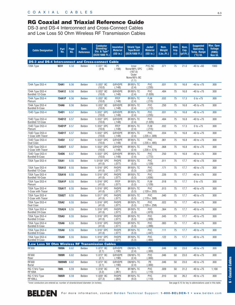
RG Coaxial and Triaxial Reference GuideDS-3 and DS-4 Interconnect and Cross-Connect Cablesand Low Loss 50 Ohm Wireless RF Transmission Cables
Nom.Cap.
(pF/Ft.)
Nom.Weight
(Lbs./Ft.)
Shield TypeTape/Braid
(DCR/1000 Ft.)
Nom.Imp.(Ω)
InsulationMaterial(OD in.)
JacketMaterial(OD in.)
ConductorStranding/
Dia. & Type*(DCR/1000 Ft.)
Spec. Reference
Page No.
PartNo.
SuggestedOperating
Temp. Range(°C) UL
Max. Oper.Voltage(RMS)Non UL
Cable Designation
DS-3 and DS-4 Interconnect and Cross-connect Cable728A Type 9231 6.58 Belden 1/.031″ BC PE Inner PVC-NC .071 75 21.0 -40 to +60 1900
(9.9) (.198) None/98% SPC (.305)(187.0)Outer
None/95% BC(1.1)
734A Type DS3-4 734A1 6.56 Belden 1/.032″ BC GIFHDPE BF/85% TC PVC .031 75 16.8 -40 to +75 300(10.0) (.148) (2.4) (.235)
734A Type DS3-4 734A12 6.56 Belden 1/.032″ BC GIFHDPE BF/85% TC PVC .484 75 16.8 -40 to +75 300Bundled 12-Coax (10.0) (.148) (2.4) (1.026)734A Type DS3-4 734A1P 6.56 Belden 1/.032″ BC FFEP BF/85% TC FLM .032 75 17.3 0 to +75 300Plenum (10.0) (.148) (2.4) (.215)734A Type DS3-4 734A6 6.56 Belden 1/.032″ BC GIFHDPE BF/85% TC PVC .250 75 16.8 -45 to +75 300Bundled 6-Coax (10.0) (.148) (2.4) (.772)734D Type DS3-4 734D1 6.57 Belden 1/.032″ SPC GIFHDPE BF/85% TC PVC .031 75 16.8 -40 to +75 300
(10.0) (.148) (2.4) (.235)734D Type DS3-4 734D12 6.57 Belden 1/.032″ SPC GIFHDPE BF/85% TC PVC .484 75 16.8 -40 to +75 300Bundled 12-Coax (10.0) (.148) (2.4) (1.026)734D Type DS3-4 734D1P 6.57 Belden 1/.032″ SPC FFEP BF/85% TC FLM .032 75 17.3 0 to +75 300Plenum (10.0) (.148) (2.4) (.215)734D Type DS3-4 734D1T 6.57 Belden 1/.032″ SPC GIFHDPE BF/85% TC PVC .034 75 16.8 -40 to +75 3001-Coax with Tracer (10.0) (.148) (2.4) (.235 x .309)734D Type DS3-4 734D2 6.57 Belden 1/.032″ SPC GIFHDPE BF/85% TC PVC .061 75 16.8 -40 to +75 300Dual Coax (10.0) (.148) (2.4) (.235 x .485)734D Type DS3-4 734D2T 6.57 Belden 1/.032″ SPC GIFHDPE BF/85% TC PVC .068 75 16.8 -40 to +75 3002-Coax with Tracer (10.0) (.148) (2.4) (.235 x .574)734D Type DS3-4 734D6 6.57 Belden 1/.032″ SPC GIFHDPE BF/85% TC PVC .250 75 16.8 -40 to +75 300Bundled 6-Coax (10.0) (.148) (2.4) (.772)735A Type DS3-4 735A1 6.55 Belden 1/.0159″ SPC FHDPE BF/93% TC PVC .011 75 17.7 -40 to +75 300
(41.0) (.077) (5.3) (.129)735A Type DS3-4 735A12 6.55 Belden 1/.016″ SPC FHDPE BF/93% TC PVC .171 75 17.7 -40 to +75 300Bundled 12-Coax (41.0) (.077) (5.3) (.581)735A Type DS3-4 735A16 6.55 Belden 1/.016″ SPC FHDPE BF/93% TC PVC .226 75 17.7 -40 to +75 300Bundled 16-Coax (41.0) (.077) (5.3) (.636)735A Type DS3-4 735A1P 6.55 Belden 1/.016″ SPC FFEP BF/93% TC FLM .018 75 17.7 0 to +75 300Plenum (41.0) (.077) (5.3) (.129)735A Type DS3-4 735A1T 6.55 Belden 1/.016″ SPC FHDPE BF/93% TC PVC .013 75 17.7 -40 to +75 3001-Coax with Tracer (41.0) (.077) (5.3) (.129 x .203)735A Type DS3-4 73502T 6.55 Belden 1/.017″ SPC FHDPE BF/93% TC PVC .040 75 17.7 -40 to +75 3002-Coax with Tracer (41.0) (.077) (5.3) (.179 x .308)735A Type DS3-4 735A2 6.55 Belden 1/.016″ SPC FHDPE BF/93% TC PVC .022 75 17.7 -40 to +75 300Dual Coax (41.0) (.077) (5.3) (.129 x .258)735A Type DS3-4 735A24 6.55 Belden 1/.016″ SPC FHDPE BF/93% TC PVC .364 75 17.7 -40 to +75 300Bundled 24-Coax (41.0) (.077) (5.3) (.870)735A Type DS3-4 735A3 6.55 Belden 1/.016″ SPC FHDPE BF/93% TC PVC .045 75 17.7 -40 to +75 300Bundled 3-Coax (41.0) (.077) (5.3) (.309)735A Type DS3-4 735A6 6.55 Belden 1/.016″ SPC FHDPE BF/93% TC PVC .083 75 17.7 -40 to +75 300Bundled 6-Coax (41.0) (.077) (5.3) (.399)735A Type DS3-4 735A8 6.55 Belden 1/.016″ SPC FHDPE BF/93% TC PVC .111 75 17.7 -40 to +75 300Bundled 8-Coax (41.0) (.077) (5.3) (.447)735A Type DS3-4 735A9 6.55 Belden 1/.016″ SPC FHDPE BF/93% TC PVC .122 75 17.7 -40 to +75 300Bundled 9-Coax (41.0) (.077) (5.3) (.484)
Low Loss 50 Ohm Wireless RF Transmission CablesRF300 7809A 6.62 Belden 1/.072″ BC GIFHDPE DB/95% TC PE .046 50 23.0 -40 to +75 300
(2.1) (.190) (2.4) (.300)RF300 7809R 6.62 Belden 1/.072″ BC GIFHDPE DB/95% TC PVC .046 50 23.0 -40 to +75 300Riser (2.1) (.190) (2.4) (.300)RF300 7809WB 6.62 Belden 1/.072″ BC GIFHDPE DB/95% TC PE .046 50 23.0 -40 to +75 300Burial (2.1) (.190) (2.4) (.300)RG-174/U Type 7805 6.59 Belden 1/.018″ BC PE BF/90% TC PVC .009 50 31.2 -40 to +75 1,100RF100A (3.2) (.061) (9.1) (.110)RG-174/U Type 7805R 6.59 Belden 1/.020″ BC FHDPE BF/93% TC PVC .010 50 26.2 -40 to +75 300RF100LL (27.3) (.060) (9.3) (.110)*Inner conductors are entered as: number of strands/strand diameter (in inches). See page 6.15 for key to abbreviations used in this table.
C O A X I A L C A B L E S 6.4
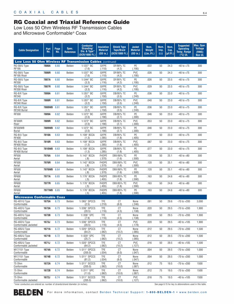
RG Coaxial and Triaxial Reference GuideLow Loss 50 Ohm Wireless RF Transmission Cablesand Microwave Conformable® Coax
F o r m o r e i n f o r m a t i o n , c o n t a c t B e l d e n Te c h n i c a l S u p p o r t : 1 - 8 0 0 - B E L D E N - 1 • w w w . b e l d e n . c o m
Low Loss 50 Ohm Wireless RF Transmission Cables (continued)
RG-58/U Type 7806A 6.60 Belden 1/.037″ BC GIFPE DF/90% TC PE .022 50 24.3 -40 to +75 300RF195 (7.6) (.110) (4.2) (.195)RG-58/U Type 7806R 6.60 Belden 1/.037″ BC GIFPE DF/90% TC PVC .026 50 24.3 -40 to +75 300RF195 Riser (7.6) (.110) (4.2) (.195)RG-58/U Type 7807A 6.60 Belden 1/.044″ BC GIFPE DF/95% TC PE .026 50 23.5 -40 to +75 300RF200 (3.3) (.116) (4.2) (.195)RG-58/U Type 7807R 6.60 Belden 1/.044″ BC GIFPE DF/95% TC PVC .029 50 23.5 -40 to +75 300RF200 Riser (3.3) (.116) (4.2) (.195)RG-8/X Type 7808A 6.61 Belden 1/.057″ BC GIFPE DB/95% TC PE .036 50 23.0 -40 to +75 300RF240 (3.2) (.150) (3.5) (.240)RG-8/X Type 7808R 6.61 Belden 1/.057″ BC GIFPE DB/95% TC PVC .040 50 23.0 -40 to +75 300RF240 Riser (3.2) (.150) (3.5) (.240)RG-8/X Type 7808WB 6.61 Belden 1/.057″ BC GIFPE DB/95% TC PE .036 50 23.0 -40 to +75 300RF240 Burial (3.2) (.150) (3.5) (.240)RF300 7809A 6.62 Belden 1/.072″ BC GIFPE DB/95% TC PE .046 50 23.0 -40 to +75 300
(2.0) (.190) (2.7) (.300)RF300R 7809R 6.62 Belden 1/.072″ BC GIFPE DB/95% TC PVC .053 50 23.0 -40 to +75 300Riser (2.0) (.190) (2.7) (.300)RF300WB 7809WB 6.62 Belden 1/.072″ BC GIFPE DB/95% TC PE .046 50 23.0 -40 to +75 300Burial (2.0) (.190) (2.7) (.300)RG-8/U Type 7810A 6.63 Belden 1/.108″ BCCA GIFPE DB/95% TC PE .077 50 23.0 -40 to +75 300RF400 (1.3) (.285) (1.8) (.405)RG-8/U Type 7810R 6.63 Belden 1/.108″ BCCA GIFPE DB/95% TC PVC .087 50 23.0 -40 to +75 300RF400 Riser (1.3) (.285) (1.8) (.405)RG-8/U Type 7810WB 6.63 Belden 1/.108″ BCCA GIFPE DB/95% TC PE .077 50 23.0 -40 to +75 300RF400 Burial (1.3) (.285) (1.8) (.405)RF500 7976A 6.64 Belden 1/.142″ BCCA FHDPE DBII/90% TC PE .120 50 25.1 -40 to +80 300Aerial (.8) (.370) (1.6) (.500)RF500 7976R 6.64 Belden 1/.142″ BCCA FHDPE DBII/90% TC PVC .120 50 25.1 -40 to +80 300Aerial (.8) (.370) (1.6) (.500)RF500 7976WB 6.64 Belden 1/.142″ BCCA FHDPE DBII/90% TC PE .120 50 25.1 -40 to +80 300Aerial (.8) (.370) (1.6) (.500)RF600 7977A 6.65 Belden 1/.176″ BCCA FHDPE DBII/85% TC PE .163 50 24.6 -40 to +80 300Aerial (.5) (.455) (1.8) (.590)RF600 7977R 6.65 Belden 1/.176″ BCCA FHDPE DBII/85% TC PVC .163 50 24.6 -40 to +80 300Aerial (.5) (.455) (1.8) (.590)RF600 7977WB 6.65 Belden 1/.176″ BCCA FHDPE DBII/85% TC PE .163 50 24.6 -40 to +80 300Aerial (.5) (.455) (1.8) (.590)
Microwave Conformable CoaxRG-401/U Type 1675A 6.73 Belden 1/.065″ SPCCS TFE CT None .081 50 29.6 -70 to +200 3,000Conformable (2.5) (.210) (8.0) (.246)RG-402/U Type 1673A 6.73 Belden 1/.036″ SPCCS TFE CT None .020 50 29.5 -70 to +200 1,900Conformable (20.5) (.116) (4.5) (.138)RG-402/U Type 1673B 6.73 Belden 1/.036″ SPC TFE CT None .020 50 29.5 -70 to +200 1,900Conformable (7.9) (.116) (4.5) (.138)RG-402/U Type 1673J 6.73 Belden 1/.036″ SPCCS TFE CT PVC .020 50 29.5 -40 to +105 1,900Conformable Jacketed (20.5) (.116) (4.5) (.178)RG-405/U Type 1671A 6.72 Belden 1/.020″ SPCCS TFE CT None .012 50 29.5 -70 to +200 1,500Conformable (64.2) (.062) (10.2) (.085)RG-405/U Type 1671B 6.72 Belden 1/.020″ SPC TFE CT None .012 50 29.5 -70 to +200 1,500Conformable (25.7) (.062) (10.2) (.085)RG-405/U Type 1671J 6.72 Belden 1/.020″ SPCCS TFE CT PVC .016 50 29.5 -40 to +105 1,500Conformable Jacketed (64.2) (.062) (10.2) (.127)M17/151 Type 1674A 6.72 Belden 1/.011″ SPCCS TFE CT None .004 50 29.5 -70 to +200 1,000Conformable (205.0) (.034) (8.0) (.047)M17/151 Type 1674B 6.72 Belden 1/.011″ SPCCS TFE CT None .004 50 29.5 -70 to +200 1,000Conformable (81.2) (.034) (8.0) (.047)75 Ohm 1672A 6.74 Belden 1/.011″ SCCCS TFE CT None .012 75 19.5 -70 to +200 1500Conformable (205.0) (.062) (10.0) (.087)75 Ohm 1672B 6.74 Belden 1/.011″ SPC TFE CT None .012 75 19.5 -70 to +200 1500Conformable (11.0) (.062) (10.0) (.087)75 Ohm 1672J 6.74 Belden 1/.011″ SCCCS TFE CT PVC .016 75 19.5 -40 to +105 1500Conformable Jacketed (205.0) (.062) (10.0) (.127)*Inner conductors are entered as: number of strands/strand diameter (in inches). See page 6.15 for key to abbreviations used in this table.
Nom.Cap.
(pF/Ft.)
Nom.Weight
(Lbs./Ft.)
Shield TypeTape/Braid
(DCR/1000 Ft.)
Nom.Imp.(Ω)
InsulationMaterial(OD in.)
JacketMaterial(OD in.)
ConductorStranding/
Dia. & Type*(DCR/1000 Ft.)
Spec. Reference
Page No.
PartNo.
SuggestedOperating
Temp. Range(°C) UL
Max. Oper.Voltage(RMS)Non UL
Cable Designation
C O A X I A L C A B L E S 6.5
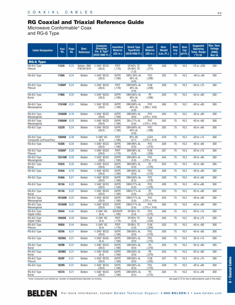
RG Coaxial and Triaxial Reference GuideMicrowave Conformable® Coaxand RG-6 Type
6 •
Coax
ial C
able
s
F o r m o r e i n f o r m a t i o n , c o n t a c t B e l d e n Te c h n i c a l S u p p o r t : 1 - 8 0 0 - B E L D E N - 1 • w w w . b e l d e n . c o m
Nom.Cap.
(pF/Ft.)
Nom.Weight
(Lbs./Ft.)
Shield TypeTape/Braid
(DCR/1000 Ft.)
Nom.Imp.(Ω)
InsulationMaterial(OD in.)
JacketMaterial(OD in.)
ConductorStranding/
Dia. & Type*(DCR/1000 Ft.)
Spec. Reference
Page No.
PartNo.
SuggestedOperating
Temp. Range(°C) UL
Max. Oper.Voltage(RMS)Non UL
Cable Designation
RG-6 TypeRG-6/U Type 1152A 6.25 Belden, IBM 1/.040″ BCCS FFEP DF/60% TC FEP .048 75 16.5 -70 to +200 300Plenum P/N1501919 (28.0) (.170) DF/40% TC (.273)
(1.8)RG-6/U Type 1189A 6.24 Belden 1/.040″ BCCS GIFPE DBIV, 60% AL PVC .032 75 16.2 -40 to +80 300
(28.0) (.180) 40% AL (.298)(4.8)
RG-6/U Type 1189AP 6.24 Belden 1/.040″ BCCS FFEP DBIV/60% AL FLM .039 75 16.3 -20 to +75 300Plenum (28.0) (.170) 40% AL (.248)
(4.8)RG-6/U Type 1190A 6.25 Belden 1/.040″ BCCS GIFPE DBIV/60% AL PE .029 75 16.2 -55 to +80 300Burial (28.0) (.180) 40% AL (.298)
(4.8)RG-6/U Type 1191AM 6.24 Belden 1/.040″ BCCS GIFPE DBIV/60% AL PVC .040 75 16.2 -40 to +80 300Messengered (28.0) (.180) 40% AL (.298 x .433)
(4.8)RG-6/U Type 1258AM 6.19 Belden 1/.040″ BCCS GIFPE DBII/60% AL PVC .042 75 16.2 -40 to +80 300Messengered (28.0) (.180) (9.0) (.270 x .410)RG-6/U Type 1260AM 6.23 Belden 1/.040″ BCCS GIFPE DB+/77% AL PVC .042 75 16.2 -40 to +80 300Messengered (28.0) (.180) (5.6) (.275 x .416)RG-6/U Type 1322R 6.24 Belden 1/.040″ BCCS GIFPE DBIV/60% AL PVC .035 75 16.2 -40 to +80 300
(28.0) (.180) 40% AL (.298)(4.8)
RG-6/U Type 1360SB 6.39 Belden 1/.040″ BC FFEP 95% BC LSZH .076 75 16.3 -30 to +75 300Composite (w/PowerPair) (6.4) (.180) (3.1) (.275 x .514)RG-6/U Type 1530A 6.20 Belden 1/.040″ BCCS GIFPE DBII/90% AL PVC .029 75 16.2 -40 to +80 300
(28.0) (.180) (5.0) (.270)RG-6/U Type 1530AP 6.20 Belden 1/.040″ BCCS FFEP DBII/90% AL FLM .027 75 16.3 -20 to +75 300Plenum (28.0) (.170) (5.0) (.235)RG-6/U Type 1531AM 6.20 Belden 1/.040″ BCCS GIFPE DBII/90% AL PVC .044 75 16.2 -40 to +80 300Messengered (28.0) (.180) (5.0) (.270 x .410)RG-6/U Type 1532A 6.20 Belden 1/.040″ BCCS GIFPE DBII/90% AL PE .024 75 16.2 -55 to +80 300Burial (28.0) (.180) (5.0) (.270)RG-6/U Type 1545A 6.19 Belden 1/.040″ BCCS GIFPE DBII/60% AL PVC .030 75 16.2 -40 to +80 300
(28.0) (.180) (9.0) (.270)RG-6/U Type 1546A 6.21 Belden 1/.040″ BCCS GIFPE DBIII/60% AL PVC .029 75 16.2 -40 to +80 300
(28.0) (.180) (6.5) (.278)RG-6/U Type 1613A 6.22 Belden 1/.040″ BCCS GIFPE DBIII/77% AL PVC .030 75 16.2 -40 to +80 300
(28.0) (.180) (5.6) (.278)RG-6/U Type 1614A 6.22 Belden 1/.040″ BCCS GIFPE DBIII/77% AL PE .024 75 16.2 -55 to +80 300Burial (28.0) (.180) (5.6) (.275)RG-6/U Type 1615AM 6.22 Belden 1/.040″ BCCS GIFPE DBIII/77% AL PVC .043 75 16.2 -40 to +80 300Messengered (28.0) (.180) (5.6) (.275 x .416)RG-6/U Type 1616AM 6.22 Belden 1/.040″ BCCS GIFPE DBIII/77% AL PVC .045 75 16.2 -40 to +80 300Messengered (28.0) (.180) (5.6) (.275 x .416)RG-6/U Type 1694A 6.44 Belden 1/.040″ BC GIFHDPE DF/95% TC PVC .040 75 16.2 -20 to +75 300Digital Video (6.4) (.180) (2.8) (.275)RG-6/U Type 1694SB 6.44 Belden 1/.040″ BC FFEP DF/95% TC FLM .045 75 16.2 -30 to +75 300Digital Video (6.4) (.170) (2.8) (.234)RG-6/U Type 1695A 6.44 Belden 1/.040″ BC FFEP DF/95% TC FLM .033 75 16.2 -40 to +80 300Plenum (6.4) (.170) (2.8) (.234)RG-6/U Type 1829A 6.31 Belden 1/.040″ BCCS GIFPE DBII/60% AL PVC .030 75 16.2 -40 to +80 300
(28.0) (.180) (9.0) (.270)RG-6/U Type 1829AC 6.31 Belden 1/.040″ BCAC GIFPE DBII/60% AL PVC .030 75 16.2 -30 to +75 300
(6.4) (.180) (9.0) (.270)RG-6/U Type 1829B 6.31 Belden 1/.040″ BCCS GIFPE DBII/60% AL PE .024 75 16.2 -55 to +80 300Burial (28.0) (.180) (9.0) (.270)RG-6/U Type 1829BC 6.31 Belden 1/.040″ BCAC GIFPE DBII/60% AL PE .024 75 16.2 -55 to +80 300Burial (6.4) (.180) (9.0) (.270)RG-6/U Type 1829P 6.31 Belden 1/.040″ BCCS GIFPE DBII/60% AL FLM .027 75 16.3 -20 to +75 300Plenum (28.0) (.180) (9.0) (.235)RG-6/U Type 1829R 6.31 Belden 1/.040″ BCCS GIFPE DBII/60% AL PVC .029 75 16.2 -40 to +80 300
(28.0) (.180) (9.0) (.270)RG-6/U Type 1837A 6.21 Belden 1/.040″ BCCS GIFPE DBIII/60% AL PE .024 75 16.2 -55 to +80 300Burial (28.0) (.180) (6.5) (.275)*Inner conductors are entered as: number of strands/strand diameter (in inches). See page 6.15 for key to abbreviations used in this table.
C O A X I A L C A B L E S 6.6
F o r m o r e i n f o r m a t i o n , c o n t a c t B e l d e n Te c h n i c a l S u p p o r t : 1 - 8 0 0 - B E L D E N - 1 • w w w . b e l d e n . c o m
Nom.Cap.
(pF/Ft.)
Nom.Weight
(Lbs./Ft.)
Shield TypeTape/Braid
(DCR/1000 Ft.)
Nom.Imp.(Ω)
InsulationMaterial(OD in.)
JacketMaterial(OD in.)
ConductorStranding/
Dia. & Type*(DCR/1000 Ft.)
Spec. Reference
Page No.
PartNo.
SuggestedOperating
Temp. Range(°C) UL
Max. Oper.Voltage(RMS)Non UL
Cable Designation
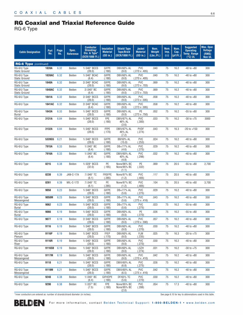
RG Coaxial and Triaxial Reference GuideRG-6 Type
RG-6 Type (continued)
RG-6/U Type 1839A 6.32 Belden 1/.040″ BCCS GIFPE DBII/60% AL PVC .040 75 16.2 -40 to +80 300Static Ground (28.0) (.180) (9.0) (.270 x .405)RG-6/U Type 1839AC 6.32 Belden 1/.040″ BCAC GIFPE DBII/60% AL PVC .040 75 16.2 -40 to +80 300Static Ground (6.4) (.180) (9.0) (.270 x .405)RG-6/U Type 1840A 6.32 Belden 2/.040″ BCAC GIFPE DBII/60% AL PVC .069 75 16.2 -40 to +80 300Static Ground (28.0) (.180) (9.0) (.273 x .703)RG-6/U Type 1840AC 6.32 Belden 2/.040″ BC GIFPE DBII/60% AL PVC .069 75 16.2 -40 to +80 300Static Ground (6.4) (.180) (9.0) (.273 x .703)RG-6/U Type 1841A 6.32 Belden 2/.040″ BCCS GIFPE DBII/60% AL PVC .058 75 16.2 -40 to +80 300
(28.0) (.180) (9.0) (.273 x .595)RG-6/U Type 1841AC 6.32 Belden 2/.040″ BCAC GIFPE DBII/60% AL PVC .058 75 16.2 -40 to +80 300
(6.4) (.180) (9.0) (.273 x .595)RG-6/U Type 1843A 6.33 Belden 1/.040″ BCCS GIFPE DBII/60% AL PE .052 75 16.2 -55 to +80 300Burial (28.0) (.180) (9.0) (.273 x .750)RG-6/U Type 3131A 6.84 Belden 1/.040″ BCCS FPE DBIV/67% AL PVC .033 75 16.2 -30 to +75 3000
(28.0) (.180) 46% AL (.300)(3.6)
RG-6/U Type 3132A 6.84 Belden 1/.040″ BCCS FFPE DBIV/67% AL PVDF .043 75 16.3 -20 to +150 300(28.0) (.170) 46% AL (.274)
(7.2)RG-6/U Type 5339G5 6.21 Belden 1/.040″ BCCS GIFPE BB/50% AL PVC .024 75 16.2 -40 to +80 300
(28.0) (.180) (15.0) (.253)RG-6/U Type 7915A 6.33 Belden 1/.040″ BC GIFPE DB+/77% AL PVC .029 75 16.2 -40 to +80 300
(6.4) (.180) (4.6) (.275)RG-6/U Type 7916A 6.33 Belden 1/.040″ BC GIFPE DBIV/60% AL PVC .032 75 16.2 -40 to +80 300
(6.4) (.180) 40% AL (.298)(4.8)
RG-6/U Type 8215 6.38 Belden 1/.028″ BCCS PE None/96% BC PE .069 75 20.5 -55 to +80 2,700(32.0) (.185) None/95% BC (.332)
(1.1)
RG-6/U Type 8238 6.39 JAN-C-17A 7/.048″ TC FRSFPE None/97% BC PVC .117 75 20.5 -40 to +80 300(6.1) (.285) (1.2) (.405)
RG-6/U Type 8261 6.39 MIL-C-17D 7/.048″ TC PE None/97% BC PVC .104 75 20.5 -40 to +60 3,700(6.1) (.285) (1.2) (.405)
RG-6/U Type 9058 6.23 Belden 1/.040″ BCCS GIFPE DB+/77% AL PVC .029 75 16.2 -40 to +80 300(28.0) (.180) (5.6) (.275)
RG-6/U Type 9058M 6.23 Belden 1/.040″ BCCS GIFPE DB+/77% AL PVC .043 75 16.2 -40 to +80 350Messengered (28.0) (.180) (5.6) (.275 x .416)RG-6/U Type 9062 6.23 Belden 1/.040″ BCCS GIFPE DB+/77% AL PVC .023 75 16.2 -55 to +80 300Burial (28.0) (.180) (5.6) (.275)RG-6/U Type 9066 6.19 Belden 1/.040″ BCCS GIFPE DBII/60% AL PE .026 75 16.2 -55 to +80 300Burial (28.0) (.180) (9.0) (.270)RG-6/U Type 9077 6.19 Belden 2/.040″ BCCS GIFPE DBII/60% AL PVC .057 75 16.2 -40 to +80 300
(28.0) (.180) (9.0) (.270 x .590)RG-6/U Type 9116 6.19 Belden 1/.040″ BCCS GIFPE DBII/60% AL PVC .030 75 16.2 -40 to +80 300
(28.0) (.180) (9.0) (.270)RG-6/U Type 9116P 6.19 Belden 1/.040″ BCCS FFEP DBII/60% AL FLM .025 75 16.3 -20 to +75 300Plenum (28.0) (.170) (9.0) (.235)RG-6/U Type 9116R 6.19 Belden 1/.040″ BCCS GIFPE DBII/60% AL PVC .030 75 16.2 -40 to +80 300Riser (28.0) (.180) (9.0) (.270)RG-6/U Type 9116SB 6.19 Belden 1/.040″ BCCS GIFPE DBII/60% AL LSZH .031 75 16.2 -30 to +75 300
(28.0) (.180) (9.0) (.274)RG-6/U Type 9117M 6.19 Belden 1/.040″ BCCS GIFPE DBII/60% AL PVC .042 75 16.2 -40 to +80 300Messengered (28.0) (.180) (9.0) (.270 x .410)RG-6/U Type 9118 6.21 Belden 1/.040″ BCCS GIFPE DBIII/60% AL PVC .026 75 16.2 -40 to +80 300
(28.0) (.180) (6.8) (.275)RG-6/U Type 9119M 6.21 Belden 1/.040″ BCCS GIFPE DBIII/60% AL PVC .042 75 16.2 -40 to +80 300Messengered (28.0) (.180) (6.5) (.275 x .416)RG-6/U Type 9248 6.38 Belden 1/.040″ BC GIFHDPE DF/65% TC PVC .030 75 16.2 -40 to +80 300
(6.4) (.180) (5.6) (.270)RG-6/U Type 9290 6.38 Belden 1/.037″ BC FPE None/95% BC PVC .054 75 17.3 -40 to +80 300
(7.5) (.180) None/95% BC (.288)(2.0)
*Inner conductors are entered as: number of strands/strand diameter (in inches). See page 6.15 for key to abbreviations used in this table.
C O A X I A L C A B L E S 6.7
6 •
Coax
ial C
able
s
F o r m o r e i n f o r m a t i o n , c o n t a c t B e l d e n Te c h n i c a l S u p p o r t : 1 - 8 0 0 - B E L D E N - 1 • w w w . b e l d e n . c o m
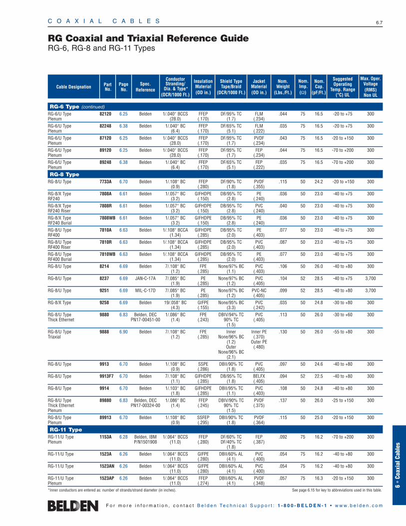
RG Coaxial and Triaxial Reference GuideRG-6, RG-8 and RG-11 Types
Nom.Cap.
(pF/Ft.)
Nom.Weight
(Lbs./Ft.)
Shield TypeTape/Braid
(DCR/1000 Ft.)
Nom.Imp.(Ω)
InsulationMaterial(OD in.)
JacketMaterial(OD in.)
ConductorStranding/
Dia. & Type*(DCR/1000 Ft.)
Spec. Reference
Page No.
PartNo.
SuggestedOperating
Temp. Range(°C) UL
Max. Oper.Voltage(RMS)Non UL
Cable Designation
RG-6 Type (continued)
RG-6/U Type 82120 6.25 Belden 1/.040″ BCCS FFEP DF/95% TC FLM .044 75 16.5 -20 to +75 300Plenum (28.0) (.170) (1.7) (.234)RG-6/U Type 82248 6.38 Belden 1/.040″ BC FFEP DF/65% TC FLM .035 75 16.5 -20 to +75 300Plenum (6.4) (.170) (5.1) (.222)RG-6/U Type 87120 6.25 Belden 1/.040″ BCCS FFEP DF/95% TC PVDF .043 75 16.5 -20 to +150 300Plenum (28.0) (.170) (1.7) (.234)RG-6/U Type 89120 6.25 Belden 1/.040″ BCCS FFEP DF/95% TC FEP .044 75 16.5 -70 to +200 300Plenum (28.0) (.170) (1.7) (.234)RG-6/U Type 89248 6.38 Belden 1/.040″ BC FFEP DF/65% TC FEP .035 75 16.5 -70 to +200 300Plenum (6.4) (.170) (5.1) (.222)
RG-8 TypeRG-8/U Type 7733A 6.70 Belden 1/.108″ BC FFEP DF/90% TC PVDF .115 50 24.2 -20 to +150 300
(0.9) (.280) (1.8) (.355)RG-8/X Type 7808A 6.61 Belden 1/.057″ BC GIFHDPE DB/95% TC PE .036 50 23.0 -40 to +75 300RF240 (3.2) (.150) (2.8) (.240)RG-8/X Type 7808R 6.61 Belden 1/.057″ BC GIFHDPE DB/95% TC PVC .040 50 23.0 -40 to +75 300RF240 Riser (3.2) (.150) (2.8) (.240)RG-8/X Type 7808WB 6.61 Belden 1/.057″ BC GIFHDPE DB/95% TC PE .036 50 23.0 -40 to +75 300RF240 Burial (3.2) (.150) (2.8) (.240)RG-8/U Type 7810A 6.63 Belden 1/.108″ BCCA GIFHDPE DB/95% TC PE .077 50 23.0 -40 to +75 300RF400 (1.34) (.285) (2.0) (.403)RG-8/U Type 7810R 6.63 Belden 1/.108″ BCCA GIFHDPE DB/95% TC PVC .087 50 23.0 -40 to +75 300RF400 Riser (1.34) (.285) (2.0) (.403)RG-8/U Type 7810WB 6.63 Belden 1/.108″ BCCA GIFHDPE DB/95% TC PE .077 50 23.0 -40 to +75 300RF400 Burial (1.34) (.285) (2.0) (.403)RG-8/U Type 8214 6.69 Belden 7/.108″ BC FPE None/97% BC PVC .106 50 26.0 -40 to +80 300
(1.2) (.285) (1.1) (.403)RG-8/U Type 8237 6.69 JAN-C-17A 7/.085″ BC PE None/97% BC PVC .104 52 28.5 -40 to +75 3,700
(1.9) (.285) (1.2) (.405)RG-8/U Type 9251 6.69 MIL-C-17D 7/.085″ BC PE None/97% BC PVC-NC .099 52 28.5 -40 to +80 3,700
(1.9) (.285) (1.2) (.405)RG-8/X Type 9258 6.69 Belden 19/.058″ BC GIFPE None/95% BC PVC .035 50 24.8 -30 to +80 300
(4.3) (.155) (3.3) (.242)RG-8/U Type 9880 6.83 Belden, DEC 1/.086″ BC FPE DBIV/94% TC PVC .113 50 26.0 -30 to +60 300Thick Ethernet PN17-00451-00 (1.4) (.243) 90% TC (.405)
(1.5)RG-8/U Type 9888 6.90 Belden 7/.108″ BC FPE Inner Inner PE .130 50 26.0 -55 to +80 300Triaxial (1.2) (.285) None/96% BC (.370)
(1.2) Outer PEOuter (.480)
None/96% BC(2.1)
RG-8/U Type 9913 6.70 Belden 1/.108″ BC SSPE DBII/90% TC PVC .097 50 24.6 -40 to +80 300(0.9) (.286) (1.8) (.405)
RG-8/U Type 9913F7 6.70 Belden 7/.108″ BC GIFHDPE DB/95% TC BELFX .094 52 22.5 -40 to +80 300(1.1) (.285) (1.8) (.405)
RG-8/U Type 9914 6.70 Belden 1/.103″ BC GIFHDPE DBII/95% TC PVC .108 50 24.8 -40 to +80 300(1.8) (.285) (1.1) (.403)
RG-8/U Type 89880 6.83 Belden, DEC 1/.086″ BC FFEP DBIV/90% TC PVDF .137 50 26.0 -25 to +150 300Thick Ethernet PN17-00324-00 (1.4) (.245) 90% TC (.375)Plenum (1.5)RG-8/U Type 89913 6.70 Belden 1/.108″ BC SSFEP DBII/90% TC PVDF .115 50 25.0 -20 to +150 300Plenum (0.9) (.295) (1.8) (.364)
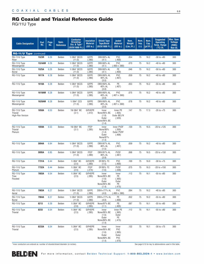
RG-11 TypeRG-11/U Type 1153A 6.28 Belden, IBM 1/.064″ BCCS FFEP DF/60% TC FEP .092 75 16.2 -70 to +200 300Plenum P/N1501908 (11.0) (.280) DF/40% TC (.387)
(1.8)RG-11/U Type 1523A 6.26 Belden 1/.064″ BCCS GIFPE DBII/60% AL PVC .054 75 16.2 -40 to +80 300
(11.0) (.280) (4.1) (.400)RG-11/U Type 1523AN 6.26 Belden 1/.064″ BCCS GIFPE DBII/60% AL PVC .054 75 16.2 -40 to +80 300
(11.0) (.280) (4.1) (.400)RG-11/U Type 1523AP 6.26 Belden 1/.064″ BCCS FFEP DBII/60% AL PVDF .057 75 16.3 -20 to +150 300Plenum (11.0) (.274) (4.1) (.348)*Inner conductors are entered as: number of strands/strand diameter (in inches). See page 6.15 for key to abbreviations used in this table.
C O A X I A L C A B L E S 6.8
F o r m o r e i n f o r m a t i o n , c o n t a c t B e l d e n Te c h n i c a l S u p p o r t : 1 - 8 0 0 - B E L D E N - 1 • w w w . b e l d e n . c o m
RG Coaxial and Triaxial Reference GuideRG/11U Type
Nom.Cap.
(pF/Ft.)
Nom.Weight
(Lbs./Ft.)
Shield TypeTape/Braid
(DCR/1000 Ft.)
Nom.Imp.(Ω)
InsulationMaterial(OD in.)
JacketMaterial(OD in.)
ConductorStranding/
Dia. & Type*(DCR/1000 Ft.)
Spec. Reference
Page No.
PartNo.
SuggestedOperating
Temp. Range(°C) UL
Max. Oper.Voltage(RMS)Non UL
Cable Designation
RG-11/U Type (continued)
RG-11/U Type 1523R 6.26 Belden 1/.064″ BCCS GIFPE DBII/60% AL PVC .054 75 16.2 -30 to +80 300Riser (11.0) (.280) (4.1) (.400)RG-11/U Type 1524AM 6.26 Belden 1/.064″ BCCS GIFPE DBII/60% AL PVC .070 75 16.2 -40 to +80 300Messengered (11.0) (.280) (4.1) (.400 x .580)RG-11/U Type 1525A 6.26 Belden 1/.064″ BCCS GIFPE DBII/60% AL PE .046 75 16.2 -50 to +80 300Burial (11.0) (.280) (4.1) (.400)RG-11/U Type 1617A 6.28 Belden 1/.064″ BCCS GIFPE DBIV/60% AL PVC .059 75 16.2 -40 to +80 300
(11.0) (.280) 40% AL (.407)(3.0)
RG-11/U Type 1618A 6.28 Belden 1/.064″ BCCS GIFPE DBIV/60% AL PE .053 75 16.2 -55 to +80 300(11.0) (.280) 40% AL (.407)
(3.0)RG-11/U Type 1619AM 6.28 Belden 1/.064″ BCCS GIFPE DBIV/60% AL PVC .075 75 16.2 -40 to +80 300Messengered (11.0) (.280) 40% AL (.407 x .560)
(3.0)RG-11/U Type 1620AM 6.28 Belden 1/.064″ CCS GIFPE DBIV/60% AL PVC .078 75 16.2 -40 to +80 300Messengered (11.0) (.280) 40% AL (.407 x .560)
(3.0)RG-11/U Type 1858A 6.53 Belden 19/.064″ BC GIFHDPE Inner Inner PE .147 75 17.3 -35 to +75 300Triaxial (3.1) (.312) None/95% BC (.405)High-Flex Version (1.8) Outer BELFX
Outer (.520)None/95% BC
(1.4)RG-11/U Type 1859A 6.53 Belden 19/.064″ BC FFEP Inner Inner PVDF .120 75 16.5 -20 to +125 300Triaxial (3.1) (.285) None/95% (.350)Plenum (1.4) Outer PVDF
Outer (.406)None/87%
(1.4)RG-11/U Type 3094A 6.84 Belden 1/.064″ BCCS GIFPE DBIV/67% AL PVC .059 75 16.2 -40 to +80 300
(11.0) (.280) 46% AL (.407)(1.5)
RG-11/U Type 3095A 6.85 Belden 1/.064″ BCCS FFEP DBIV/67% AL PVDF .068 75 16.5 -20 to +150 300(11.0) (.280) 46% AL (.387)
(3.9)RG-11/U Type 7731A 6.44 Belden 1/.064″ BC GIFHDPE DF/95% TC PVC .100 75 16.0 -30 to +75 300
(2.5) (.280) (1.5) (.400)RG-11/U Type 7732A 6.44 Belden 1/.064″ BC FFEP DF/95% TC PVDF .075 75 16.3 -20 to +150 300Plenum (2.5) (.274) (1.6) (.348)RG-11/U Type 7803A 6.54 Belden 1/.064″ BC GIFHDPE Inner Inner .112 75 16.1 -55 to +80 300Triax (2.5) (.285) None/95% BC PEFlooded (1.6) (.365)
Outer OuterNone/95% BC PE
(1.4) (.475)
RG-11/U Type 7983A 6.27 Belden 1/.064″ BCCS GIFPE DBIII+/77% AL PVC .084 75 16.2 -40 to +80 300Aerial (11.0) (.280) (4.0) (.400 x .580)
RG-11/U Type 7984A 6.27 Belden 1/.064″ BCCS GIFPE DBIII+/77% AL PE .052 75 16.2 -55 to +80 300Burial (11.0) (.280) (4.0) (.400)RG-11/U Type 8213 6.39 Belden 1/.064″ BC GIFHDPE None/97% BC PE .087 75 16.1 -55 to +80 300
(2.6) (.285) (1.1) (.405)RG-11/U Type 8233 6.54 Belden 1/.064″ BC GIFHDPE Inner Inner PE .112 75 16.1 -55 to +80 300Triaxial (2.5) (.285) None/95% BC (.365)
(1.6) OuterOuter PE
None/80% BC (.475)(1.4)
RG-11/U Type 8233A 6.54 Belden 1/.064″ BC GIFHDPE Inner Inner .132 75 16.1 -30 to +75 300Triaxial (2.5) (.285) None/95% BC PVC
(1.6) (.365)Outer Outer
None/80% BC PVC(1.4) (.475)
*Inner conductors are entered as: number of strands/strand diameter (in inches). See page 6.15 for key to abbreviations used in this table.
C O A X I A L C A B L E S 6.9
6 •
Coax
ial C
able
s
F o r m o r e i n f o r m a t i o n , c o n t a c t B e l d e n Te c h n i c a l S u p p o r t : 1 - 8 0 0 - B E L D E N - 1 • w w w . b e l d e n . c o m
RG Coaxial and Triaxial Reference GuideRG/11U and RG-58 Types
Nom.Cap.
(pF/Ft.)
Nom.Weight
(Lbs./Ft.)
Shield TypeTape/Braid
(DCR/1000 Ft.)
Nom.Imp.(Ω)
InsulationMaterial(OD in.)
JacketMaterial(OD in.)
ConductorStranding/
Dia. & Type*(DCR/1000 Ft.)
Spec. Reference
Page No.
PartNo.
SuggestedOperating
Temp. Range(°C) UL
Max. Oper.Voltage(RMS)Non UL
Cable Designation
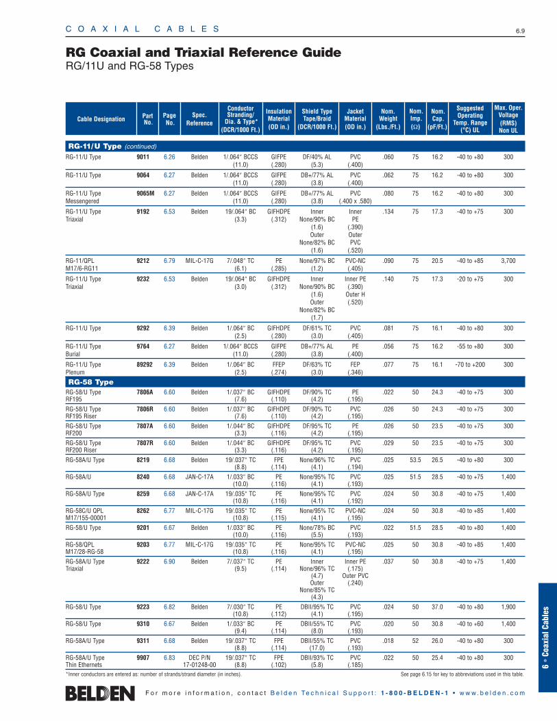
RG-11/U Type (continued)
RG-11/U Type 9011 6.26 Belden 1/.064″ BCCS GIFPE DF/40% AL PVC .060 75 16.2 -40 to +80 300(11.0) (.280) (5.3) (.400)
RG-11/U Type 9064 6.27 Belden 1/.064″ BCCS GIFPE DB+/77% AL PVC .062 75 16.2 -40 to +80 300(11.0) (.280) (3.8) (.400)
RG-11/U Type 9065M 6.27 Belden 1/.064″ BCCS GIFPE DB+/77% AL PVC .080 75 16.2 -40 to +80 300Messengered (11.0) (.280) (3.8) (.400 x .580)
RG-11/U Type 9192 6.53 Belden 19/.064″ BC GIFHDPE Inner Inner .134 75 17.3 -40 to +75 300Triaxial (3.3) (.312) None/90% BC PE
(1.6) (.390)Outer Outer
None/82% BC PVC(1.6) (.520)
RG-11/QPL 9212 6.79 MIL-C-17G 7/.048″ TC PE None/97% BC PVC-NC .090 75 20.5 -40 to +85 3,700M17/6-RG11 (6.1) (.285) (1.2) (.405)
RG-11/U Type 9232 6.53 Belden 19/.064″ BC GIFHDPE Inner Inner PE .140 75 17.3 -20 to +75 300Triaxial (3.0) (.312) None/90% BC (.390)
(1.6) Outer HOuter (.520)
None/82% BC(1.7)
RG-11/U Type 9292 6.39 Belden 1/.064″ BC GIFHDPE DF/61% TC PVC .081 75 16.1 -40 to +80 300(2.5) (.280) (3.0) (.405)
RG-11/U Type 9764 6.27 Belden 1/.064″ BCCS GIFPE DB+/77% AL PE .056 75 16.2 -55 to +80 300Burial (11.0) (.280) (3.8) (.400)
RG-11/U Type 89292 6.39 Belden 1/.064″ BC FFEP DF/63% TC FEP .077 75 16.1 -70 to +200 300Plenum (2.5) (.274) (3.0) (.346)
RG-58 TypeRG-58/U Type 7806A 6.60 Belden 1/.037″ BC GIFHDPE DF/90% TC PE .022 50 24.3 -40 to +75 300RF195 (7.6) (.110) (4.2) (.195)RG-58/U Type 7806R 6.60 Belden 1/.037″ BC GIFHDPE DF/90% TC PVC .026 50 24.3 -40 to +75 300RF195 Riser (7.6) (.110) (4.2) (.195)RG-58/U Type 7807A 6.60 Belden 1/.044″ BC GIFHDPE DF/95% TC PE .026 50 23.5 -40 to +75 300RF200 (3.3) (.116) (4.2) (.195)RG-58/U Type 7807R 6.60 Belden 1/.044″ BC GIFHDPE DF/95% TC PVC .029 50 23.5 -40 to +75 300RF200 Riser (3.3) (.116) (4.2) (.195)RG-58A/U Type 8219 6.68 Belden 19/.037″ TC FPE None/96% TC PVC .025 53.5 26.5 -40 to +80 300
(8.8) (.114) (4.1) (.194)RG-58A/U 8240 6.68 JAN-C-17A 1/.033″ BC PE None/95% TC PVC .025 51.5 28.5 -40 to +75 1,400
(10.0) (.116) (4.1) (.193)RG-58A/U Type 8259 6.68 JAN-C-17A 19/.035″ TC PE None/95% TC PVC .024 50 30.8 -40 to +75 1,400
(10.8) (.116) (4.1) (.192)RG-58C/U QPL 8262 6.77 MIL-C-17G 19/.035″ TC PE None/95% TC PVC-NC .024 50 30.8 -40 to +85 1,400M17/155-00001 (10.8) (.115) (4.1) (.195)RG-58/U Type 9201 6.67 Belden 1/.033″ BC PE None/78% BC PVC .022 51.5 28.5 -40 to +80 1,400
(10.0) (.116) (5.5) (.193)RG-58/QPL 9203 6.77 MIL-C-17G 19/.035″ TC PE None/95% TC PVC-NC .025 50 30.8 -40 to +85 1,400M17/28-RG-58 (10.8) (.116) (4.1) (.195)RG-58A/U Type 9222 6.90 Belden 7/.037″ TC PE Inner Inner PE .037 50 30.8 -40 to +75 1,400Triaxial (9.5) (.114) None/96% TC (.175)
(4.7) Outer PVCOuter (.240)
None/85% TC(4.3)
RG-58/U Type 9223 6.82 Belden 7/.030″ TC PE DBII/95% TC PVC .024 50 37.0 -40 to +80 1,900(10.8) (.112) (4.1) (.195)
RG-58/U Type 9310 6.67 Belden 1/.033″ BC PE DBII/55% TC PVC .020 50 30.8 -40 to +60 1,400(9.4) (.114) (8.0) (.193)
RG-58A/U Type 9311 6.68 Belden 19/.037″ TC FPE DBII/55% TC PVC .018 52 26.0 -40 to +80 300(8.8) (.114) (17.0) (.193)
RG-58A/U Type 9907 6.83 DEC P/N 19/.037″ TC FPE DBII/93% TC PVC .022 50 25.4 -40 to +80 300Thin Ethernets 17-01248-00 (8.8) (.102) (5.8) (.185)*Inner conductors are entered as: number of strands/strand diameter (in inches). See page 6.15 for key to abbreviations used in this table.
C O A X I A L C A B L E S 6.10
F o r m o r e i n f o r m a t i o n , c o n t a c t B e l d e n Te c h n i c a l S u p p o r t : 1 - 8 0 0 - B E L D E N - 1 • w w w . b e l d e n . c o m
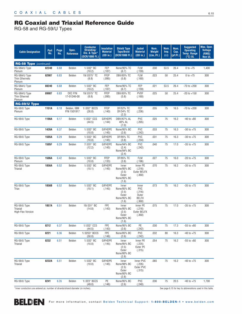
RG-58 Type (continued)
RG-58A/U Type 82240 6.68 Belden 1/.032″ BC FEP None/95% TC FLM .030 53.5 26.4 0 to +75 1,400Plenum (10.2) (.107) (6.7) (.159)RG-58A/U Type 82907 6.83 Belden 19/.0375″ TC FFEP DBII/93% TC FLM .023 50 25.4 0 to +75 300Thin Ethernets (8.8) (.095) (5.8) (.160)Plenum
RG-58A/U Type 88240 6.68 Belden 1/.032″ BC FEP None/95% TC FEP .021 53.5 26.4 -70 to +200 300Plenum (10.2) (.107) (6.7) (.159)
RG-58A/U Type 89907 6.83 DEC P/N 19/.0375″ TC FFEP DBII/93% TC PVDF .025 50 25.4 -20 to +150 300Thin Ethernet 17-01246-00 (8.8) (.095) (5.8) (.160)Plenum
RG-59/U TypeRG-59/U Type 1151A 6.18 Belden, IBM 1/.032″ BCCS FFEP DF/52% TC FEP .035 75 16.5 -70 to +200 300Plenum P/N 1501917 (26.0) (.140) DF/34% TC (.236)
(2.3)
RG-59/U Type 1186A 6.17 Belden 1/.032″ CCS GIFHDPE DBIV/67% AL PVC .025 75 16.2 -40 to +80 300(44.5) (.144) 40% AL (.265)
(7.0)
RG-59/U Type 1426A 6.37 Belden 1/.032″ BC GIFHDPE None/95% BC PVC .033 75 16.3 -30 to +75 300(10.0) (.145) (2.6) (.242)
RG-59/U Type 1505A 6.29 Belden 1/.032″ BC GIFHDPE DF/95% TC PVC .031 75 16.3 -30 to +75 300(10.0) (.145) (3.8) (.234)
RG-59/U Type 1505F 6.29 Belden 7/.031″ BC GIFHDPE None/94% BC PVC .040 75 17.0 -35 to +75 300(12.2) (.145) (2.4) (.242)
None/94% BC(2.4)
RG-59/U Type 1506A 6.42 Belden 1/.032″ BC FFEP DF/95% TC FLM .027 75 16.0 -20 to +75 300Plenum (10.0) (.133) (3.8) (.196)
RG-59/U Type 1856A 6.52 Belden 1/.032″ BC GIFHDPE Inner Inner PE .070 75 16.2 -35 to +75 300Triaxial (10.1) (.145) None/95% BC (.216)
(2.5) Outer BELFXOuter (.360)
None/95% BC(1.6)
RG-59/U Type 1856B 6.52 Belden 1/.032″ BC GIFHDPE Inner Inner .073 75 16.2 -35 to +75 300Triax (10.1) (.145) None/95% BC PVC
(2.5) (.216)Outer Outer
None/95% BC BELFX(1.6) (.360)
RG-59/U Type 1857A 6.51 Belden 19/.031″ BC FPE Inner Inner PE .075 75 17.0 -35 to +75 300Triaxial (14.0) (.143) None/95% BC (.216)High-Flex Version (2.5) Outer BELFX
Outer (.360)None/90% BC
(1.6)
RG-59/U Type 8212 6.37 Belden 1/.032″ CCS FPE None/95% BC PE .030 75 17.3 -55 to +80 300(44.5) (.143) (2.6) (.242)
RG-59/U Type 8221 6.36 Belden 1/.0253″ BCCS FPE None/85% BC PVC .032 80 16.3 -40 to +75 300(50.0) (.146) (2.6) (.242)
RG-59/U Type 8232 6.51 Belden 1/.032″ BC GIFHDPE Inner Inner PE .054 75 16.2 -55 to +80 300Triaxial (10.0) (.145) None/95% BC (.225)
(2.5) Outer PEOuter (.315)
None/80% BC(2.8)
RG-59/U Type 8232A 6.51 Belden 1/.032″ BC GIFHDPE Inner Inner PVC .065 75 16.2 -40 to +75 300Triaxial (10.0) (.145) None/98% BC (.226)
(2.5) Outer PVCOuter (.315)
None/80% BC(2.8)
RG-59/U Type 8241 6.35 Belden 1/.023″ BCCS PE None/95% BC PVC .036 75 20.5 -40 to +75 1,700(49.0) (.146) (2.6) (.240)
*Inner conductors are entered as: number of strands/strand diameter (in inches). See page 6.15 for key to abbreviations used in this table.
RG Coaxial and Triaxial Reference GuideRG-58 and RG-59/U Types
Nom.Cap.
(pF/Ft.)
Nom.Weight
(Lbs./Ft.)
Shield TypeTape/Braid
(DCR/1000 Ft.)
Nom.Imp.(Ω)
InsulationMaterial(OD in.)
JacketMaterial(OD in.)
ConductorStranding/
Dia. & Type*(DCR/1000 Ft.)
Spec. Reference
Page No.
PartNo.
SuggestedOperating
Temp. Range(°C) UL
Max. Oper.Voltage(RMS)Non UL
Cable Designation
C O A X I A L C A B L E S 6.11
6 •
Coax
ial C
able
s
F o r m o r e i n f o r m a t i o n , c o n t a c t B e l d e n Te c h n i c a l S u p p o r t : 1 - 8 0 0 - B E L D E N - 1 • w w w . b e l d e n . c o m
RG Coaxial and Triaxial Reference GuideRG-59/U Type
Nom.Cap.
(pF/Ft.)
Nom.Weight
(Lbs./Ft.)
Shield TypeTape/Braid
(DCR/1000 Ft.)
Nom.Imp.(Ω)
InsulationMaterial(OD in.)
JacketMaterial(OD in.)
ConductorStranding/
Dia. & Type*(DCR/1000 Ft.)
Spec. Reference
Page No.
PartNo.
SuggestedOperating
Temp. Range(°C) UL
Max. Oper.Voltage(RMS)Non UL
Cable Designation
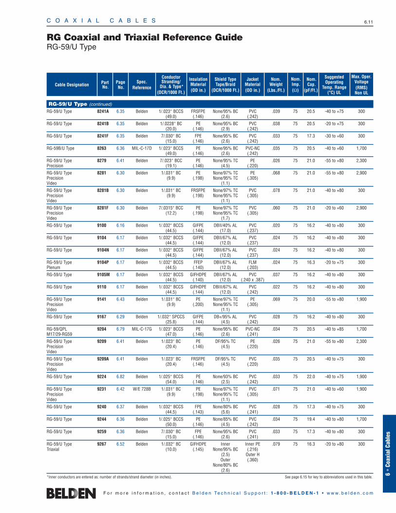
RG-59/U Type (continued)
RG-59/U Type 8241A 6.35 Belden 1/.023″ BCCS FRSFPE None/95% BC PVC .039 75 20.5 -40 to +75 300(49.0) (.146) (2.6) (.242)
RG-59/U Type 8241B 6.35 Belden 1/.0228″ BC PE None/95% BC PVC .038 75 20.5 -20 to +75 300(20.0) (.146) (2.9) (.242)
RG-59/U Type 8241F 6.35 Belden 7/.030″ BC FPE None/95% BC PVC .033 75 17.3 -30 to +60 300(15.0) (.146) (2.6) (.242)
RG-59B/U Type 8263 6.36 MIL-C-17D 1/.023″ BCCS PE None/95% BC PVC-NC .035 75 20.5 -40 to +60 1,700(49.0) (.146) (2.6) (.242)
RG-59/U Type 8279 6.41 Belden 7/.023″ BCC PE None/95% TC PE .026 75 21.0 -55 to +80 2,300Precision (19.1) (.146) (4.5) (.220)
RG-59/U Type 8281 6.30 Belden 1/.031″ BC PE None/97% TC PE .068 75 21.0 -55 to +80 2,900Precision (9.9) (.198) None/95% TC (.305)Video (1.1)
RG-59/U Type 8281B 6.30 Belden 1/.031″ BC FRSFPE None/97% TC PVC .078 75 21.0 -40 to +80 300Precision (9.9) (.198) None/95% TC (.305)Video (1.1)
RG-59/U Type 8281F 6.30 Belden 7/.0315″ BCC PE None/97% TC PVC .060 75 21.0 -20 to +60 2,900Precision (12.2) (.198) None/95% TC (.305)Video (1.7)
RG-59/U Type 9100 6.16 Belden 1/.032″ BCCS GIFPE DBII/40% AL PVC .020 75 16.2 -40 to +80 300(44.5) (.144) (17.0) (.237)
RG-59/U Type 9104 6.17 Belden 1/.032″ BCCS GIFPE DBII/67% AL PVC .024 75 16.2 -40 to +80 300(44.5) (.144) (12.0) (.237)
RG-59/U Type 9104N 6.17 Belden 1/.032″ BCCS GIFPE DBII/67% AL PVC .024 75 16.2 -40 to +80 300(44.5) (.144) (12.0) (.237)
RG-59/U Type 9104P 6.17 Belden 1/.032″ BCCS FFEP DBII/67% AL FLM .024 75 16.3 -20 to +75 300Plenum (44.5) (.140) (12.0) (.203)
RG-59/U Type 9105M 6.17 Belden 1/.032″ BCCS GIFHDPE DBII/67% AL PVC .037 75 16.2 -40 to +80 300(44.5) (.140) (12.0) (.240 x .387)
RG-59/U Type 9110 6.17 Belden 1/.032″ BCCS GIFHDPE DBIII/67% AL PVC .022 75 16.2 -40 to +80 300(44.5) (.144) (12.0) (.242)
RG-59/U Type 9141 6.43 Belden 1/.031″ BC PE None/97% TC PE .069 75 20.0 -55 to +80 1,900Precision (9.9) (.200) None/95% TC (.305)Video (1.1)
RG-59/U Type 9167 6.29 Belden 1/.032″ SPCCS GIFPE DB+/95% AL PVC .028 75 16.2 -40 to +80 300(25.8) (.144) (4.5) (.242)
RG-59/QPL 9204 6.79 MIL-C-17G 1/.023″ BCCS PE None/95% BC PVC-NC .034 75 20.5 -40 to +85 1,700M17/29-RG59 (47.0) (.146) (2.6) (.241)
RG-59/U Type 9209 6.41 Belden 1/.023″ BC PE DF/95% TC PE .026 75 21.0 -55 to +80 2,300Precision (20.4) (.146) (4.5) (.220)Video
RG-59/U Type 9209A 6.41 Belden 1/.023″ BC FRSFPE DF/95% TC PVC .035 75 20.5 -40 to +75 300Precision (20.4) (.146) (4.5) (.220)Video
RG-59/U Type 9224 6.82 Belden 1/.025″ BCCS PE None/93% BC PVC .033 75 22.0 -40 to +75 1,900(54.0) (.146) (2.5) (.242)
RG-59/U Type 9231 6.42 W/E 728B 1/.031″ BC PE None/97% TC PVC .071 75 21.0 -40 to +60 1,900Precision (9.9) (.198) None/95% TC (.305)Video (1.1)
RG-59/U Type 9240 6.37 Belden 1/.032″ BCCS FPE None/80% BC PVC .028 75 17.3 -40 to +75 300(44.5) (.143) (5.6) (.241)
RG-59/U Type 9244 6.36 Belden 1/.025″ BCCS PE None/85% BC PVC .034 75 19.4 -40 to +80 1,700(50.0) (.146) (4.5) (.242)
RG-59/U Type 9259 6.36 Belden 7/.030″ BC FPE None/95% BC PVC .033 75 17.3 -40 to +80 300(15.0) (.146) (2.6) (.241)
RG-59/U Type 9267 6.52 Belden 1/.032″ BC GIFHDPE Inner Inner PE .079 75 16.3 -20 to +80 300Triaxial (10.0) (.145) None/95% BC (.216)
(2.5) Outer HOuter (.360)
None/80% BC(2.6)
*Inner conductors are entered as: number of strands/strand diameter (in inches). See page 6.15 for key to abbreviations used in this table.
C O A X I A L C A B L E S 6.12
F o r m o r e i n f o r m a t i o n , c o n t a c t B e l d e n Te c h n i c a l S u p p o r t : 1 - 8 0 0 - B E L D E N - 1 • w w w . b e l d e n . c o m
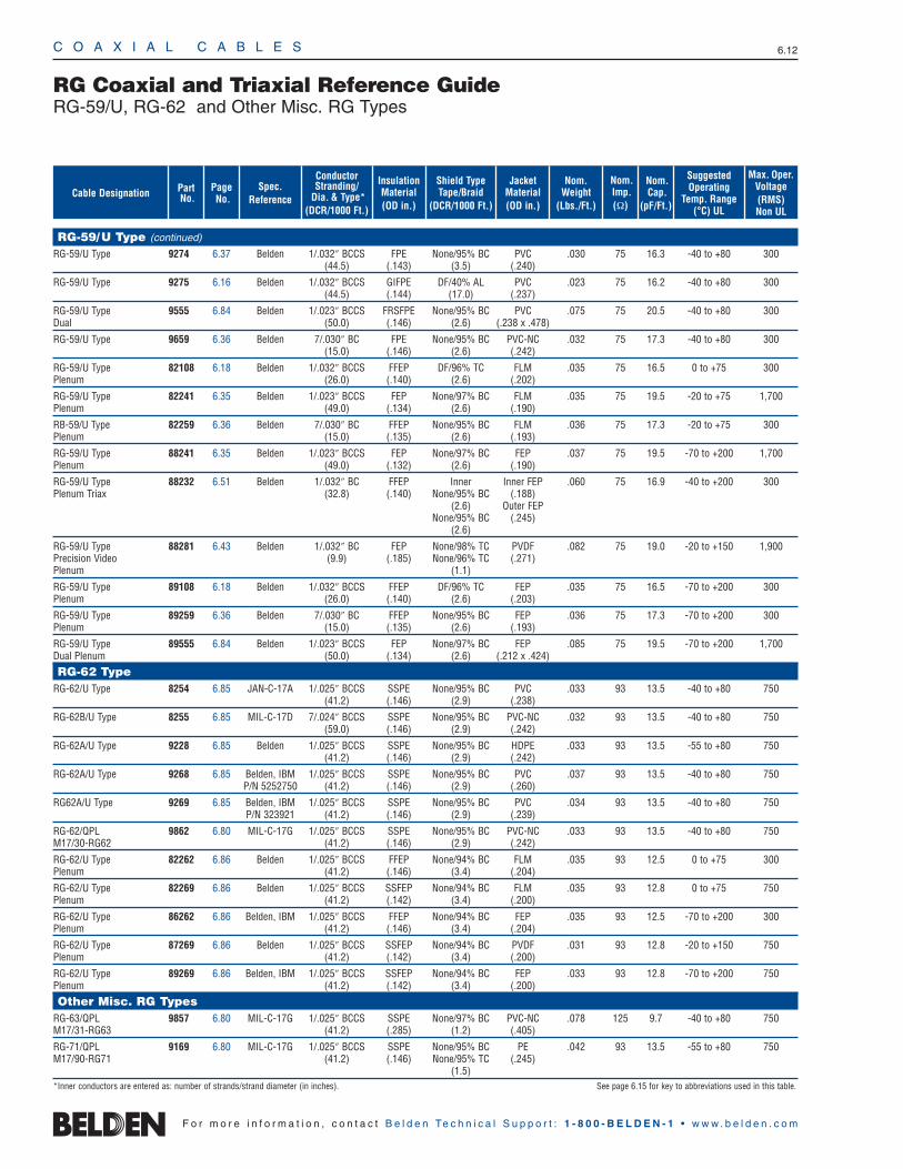
RG-59/U Type (continued)
RG-59/U Type 9274 6.37 Belden 1/.032″ BCCS FPE None/95% BC PVC .030 75 16.3 -40 to +80 300(44.5) (.143) (3.5) (.240)
RG-59/U Type 9275 6.16 Belden 1/.032″ BCCS GIFPE DF/40% AL PVC .023 75 16.2 -40 to +80 300(44.5) (.144) (17.0) (.237)
RG-59/U Type 9555 6.84 Belden 1/.023″ BCCS FRSFPE None/95% BC PVC .075 75 20.5 -40 to +80 300Dual (50.0) (.146) (2.6) (.238 x .478)
RG-59/U Type 9659 6.36 Belden 7/.030″ BC FPE None/95% BC PVC-NC .032 75 17.3 -40 to +80 300(15.0) (.146) (2.6) (.242)
RG-59/U Type 82108 6.18 Belden 1/.032″ BCCS FFEP DF/96% TC FLM .035 75 16.5 0 to +75 300Plenum (26.0) (.140) (2.6) (.202)
RG-59/U Type 82241 6.35 Belden 1/.023″ BCCS FEP None/97% BC FLM .035 75 19.5 -20 to +75 1,700Plenum (49.0) (.134) (2.6) (.190)
RB-59/U Type 82259 6.36 Belden 7/.030″ BC FFEP None/95% BC FLM .036 75 17.3 -20 to +75 300Plenum (15.0) (.135) (2.6) (.193)
RG-59/U Type 88241 6.35 Belden 1/.023″ BCCS FEP None/97% BC FEP .037 75 19.5 -70 to +200 1,700Plenum (49.0) (.132) (2.6) (.190)
RG-59/U Type 88232 6.51 Belden 1/.032″ BC FFEP Inner Inner FEP .060 75 16.9 -40 to +200 300Plenum Triax (32.8) (.140) None/95% BC (.188)
(2.6) Outer FEPNone/95% BC (.245)
(2.6)
RG-59/U Type 88281 6.43 Belden 1/.032″ BC FEP None/98% TC PVDF .082 75 19.0 -20 to +150 1,900Precision Video (9.9) (.185) None/96% TC (.271)Plenum (1.1)
RG-59/U Type 89108 6.18 Belden 1/.032″ BCCS FFEP DF/96% TC FEP .035 75 16.5 -70 to +200 300Plenum (26.0) (.140) (2.6) (.203)
RG-59/U Type 89259 6.36 Belden 7/.030″ BC FFEP None/95% BC FEP .036 75 17.3 -70 to +200 300Plenum (15.0) (.135) (2.6) (.193)
RG-59/U Type 89555 6.84 Belden 1/.023″ BCCS FEP None/97% BC FEP .085 75 19.5 -70 to +200 1,700Dual Plenum (50.0) (.134) (2.6) (.212 x .424)
RG-62 TypeRG-62/U Type 8254 6.85 JAN-C-17A 1/.025″ BCCS SSPE None/95% BC PVC .033 93 13.5 -40 to +80 750
(41.2) (.146) (2.9) (.238)
RG-62B/U Type 8255 6.85 MIL-C-17D 7/.024″ BCCS SSPE None/95% BC PVC-NC .032 93 13.5 -40 to +80 750(59.0) (.146) (2.9) (.242)
RG-62A/U Type 9228 6.85 Belden 1/.025″ BCCS SSPE None/95% BC HDPE .033 93 13.5 -55 to +80 750(41.2) (.146) (2.9) (.242)
RG-62A/U Type 9268 6.85 Belden, IBM 1/.025″ BCCS SSPE None/95% BC PVC .037 93 13.5 -40 to +80 750P/N 5252750 (41.2) (.146) (2.9) (.260)
RG62A/U Type 9269 6.85 Belden, IBM 1/.025″ BCCS SSPE None/95% BC PVC .034 93 13.5 -40 to +80 750P/N 323921 (41.2) (.146) (2.9) (.239)
RG-62/QPL 9862 6.80 MIL-C-17G 1/.025″ BCCS SSPE None/95% BC PVC-NC .033 93 13.5 -40 to +80 750M17/30-RG62 (41.2) (.146) (2.9) (.242)
RG-62/U Type 82262 6.86 Belden 1/.025″ BCCS FFEP None/94% BC FLM .035 93 12.5 0 to +75 300Plenum (41.2) (.146) (3.4) (.204)
RG-62/U Type 82269 6.86 Belden 1/.025″ BCCS SSFEP None/94% BC FLM .035 93 12.8 0 to +75 750Plenum (41.2) (.142) (3.4) (.200)
RG-62/U Type 86262 6.86 Belden, IBM 1/.025″ BCCS FFEP None/94% BC FEP .035 93 12.5 -70 to +200 300Plenum (41.2) (.146) (3.4) (.204)
RG-62/U Type 87269 6.86 Belden 1/.025″ BCCS SSFEP None/94% BC PVDF .031 93 12.8 -20 to +150 750Plenum (41.2) (.142) (3.4) (.200)
RG-62/U Type 89269 6.86 Belden, IBM 1/.025″ BCCS SSFEP None/94% BC FEP .033 93 12.8 -70 to +200 750Plenum (41.2) (.142) (3.4) (.200)
Other Misc. RG TypesRG-63/QPL 9857 6.80 MIL-C-17G 1/.025″ BCCS SSPE None/97% BC PVC-NC .078 125 9.7 -40 to +80 750M17/31-RG63 (41.2) (.285) (1.2) (.405)
RG-71/QPL 9169 6.80 MIL-C-17G 1/.025″ BCCS SSPE None/95% BC PE .042 93 13.5 -55 to +80 750M17/90-RG71 (41.2) (.146) None/95% TC (.245)
(1.5)*Inner conductors are entered as: number of strands/strand diameter (in inches). See page 6.15 for key to abbreviations used in this table.
RG Coaxial and Triaxial Reference GuideRG-59/U, RG-62 and Other Misc. RG Types
Nom.Cap.
(pF/Ft.)
Nom.Weight
(Lbs./Ft.)
Shield TypeTape/Braid
(DCR/1000 Ft.)
Nom.Imp.(Ω)
InsulationMaterial(OD in.)
JacketMaterial(OD in.)
ConductorStranding/
Dia. & Type*(DCR/1000 Ft.)
Spec. Reference
Page No.
PartNo.
SuggestedOperating
Temp. Range(°C) UL
Max. Oper.Voltage(RMS)Non UL
Cable Designation
C O A X I A L C A B L E S 6.13
6 •
Coax
ial C
able
s
F o r m o r e i n f o r m a t i o n , c o n t a c t B e l d e n Te c h n i c a l S u p p o r t : 1 - 8 0 0 - B E L D E N - 1 • w w w . b e l d e n . c o m
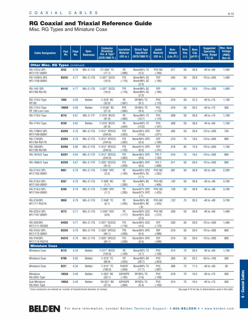
RG Coaxial and Triaxial Reference GuideMisc. RG Types and Miniature Coax
Nom.Cap.
(pF/Ft.)
Nom.Weight
(Lbs./Ft.)
Shield TypeTape/Braid
(DCR/1000 Ft.)
Nom.Imp.(Ω)
InsulationMaterial(OD in.)
JacketMaterial(OD in.)
ConductorStranding/
Dia. & Type*(DCR/1000 Ft.)
Spec. Reference
Page No.
PartNo.
SuggestedOperating
Temp. Range(°C) UL
Max. Oper.Voltage(RMS)Non UL
Cable Designation
Other Misc. RG Types (continued)
RG-122/U QPL 9252 6.76 MIL-C-17G 27/.030″ TC PE None/95% TC PVC-NC .017 50 30.8 -40 to +80 1,400M17/157-00001 (17.1) (.096) (5.2) (.160)
RG-142B/U QPL 83242 6.77 MIL-C-17G 1/.037″ SCCS TFE None/96% SC FEP .043 50 29.0 -70 to +200 1,400M17/158-00001 (19.3) (.116) None/96% SC (.195)
(2.3)
RG-142/ QPL 84142 6.77 MIL-C-17G 1/.037″ SCCS TFE None/96% SC FEP .043 50 29.0 -70 to +200 1,400M17/60-RG142 (19.3) (.116) None/96% SC (.195)
(2.3)
RG-174/U Type 7805 6.59 Belden 1/.018″ BC PE DF/90% TC PVC .010 50 31.2 -40 to +75 1,100RF100 (32.0) (.061) (9.1) (.110)
RG-174/U Type 7805R 6.59 Belden 1/.0195″ BC FPE DF/90% TC PVC .010 50 26.2 -40 to +75 300RF 100 Low Loss (27.3) (.060) (9.4) (.110)
RG-174/U Type 8216 6.67 MIL-C-17F 7/.019″ BCCS PE None/90% TC PVC .008 50 30.8 -40 to +75 1,100(97.0) (.060) (10.7) (.110)
RG-174/U Type 9239 6.82 Belden 7/.019″ BCCS PE None/90% TC PVC .008 50 38.0 -40 to +60 1,100(97.0) (.044) (14.0) (.101)
RG-178B/U QPL 83265 6.76 MIL-C-17G 7/.012″ SPCCS TFE None/95% SPC FEP .005 50 29.0 -70 to +200 750M17/169-00001 (244.0) (.033) (14.6) (.071)
RG-179/QPL 83264 6.79 MIL-C-17G 7/.012″ SPCCS TFE None/94% SPC FEP .010 75 19.5 -70 to +200 900M17/94-RG179 (244.0) (.062) (8.5) (.100)
RG-180/QPL 83266 6.80 MIL-C-17G 7/.012″ SPCCS TFE None/91% SPC FEP .018 95 15.0 -70 to +200 1,100M17/95-RG180 (244.0) (.102) (6.5) (.141)
RG-187A/U Type 83267 6.84 MIL-C-17D 7/.012″ SPCCS TFE None/95% SPC TFE-T .010 75 19.5 -70 to +200 900(244.0) (.063) (8.6) (.103)
RG-188A/U Type 83269 6.67 MIL-C-17D 7/.020″ SCCCS TFE None/96% SPC TFE-T .011 50 29.0 -70 to +200 900(91.2) (.058) (8.5) (.098)
RG-212/U QPL 9861 6.78 MIL-C-17G 1/.056″ SPC PE None/95% SPC PVC-NC .081 50 30.8 -50 to +80 2,200M17/162-00001 (3.3) (.185) None/95% SC (.332)
(1.1)
RG-213/U QPL 8267 6.78 MIL-C-17G 7/.089″ BC PE None/96% BC PVC-NC .102 50 30.8 -40 to +80 3,700M17/163-00001 (1.7) (.285) (1.2) (.405)
RG-214/U QPL 8268 6.78 MIL-C-17G 7/.089″ SPC PE None/97% SPC PVC-NC .128 50 30.8 -40 to +80 3,700M17/164-00001 (1.7) (.285) None/97% SPC (.425)
(.7)
RG-216/QPL 9850 6.79 MIL-C-17G 7/.048″ TC PE None/95% BC PVC-NC .122 75 20.5 -40 to +80 3,700M17/77-RG216 (6.1) (.285) None/95% BC (.425)
(.8)
RG-223/U QPL 9273 6.77 MIL-C-17G 1/.034″ SCC PE None/95% SCC PVC-NC .036 50 30.8 -40 to +60 1,400M17/167-00001 (8.8) (.117) None/95% SCC (.212)
(2.5)
RG-303/QPL 84303 6.77 MIL-C-17G 1/.037″ SCCCS TFE None/95% SCC FEP .030 50 29.0 -70 to +200 1,400M17/111-RG303 (16.3) (.116) (4.3) (.170)
RG-316/U QPL 83284 6.76 MIL-C-17G 7/.020″ SPCCS TFE None/95% SPC FEP .010 50 29.0 -70 to +200 900M17/172-00001 (84.1) (.058) (6.5) (.098)
RG-316/QPL 84316 6.76 MIL-C-17G 7/.020″ SPCCS TFE None/95% SPC FEP .010 50 29.0 -70 to +200 900M17/113-RG316 (84.1) (.058) (6.5) (.098)
Miniature CoaxMiniature Coax 8218 6.34 Belden 7/.017″ BCCS PE None/93% TC PVC .014 75 20.5 -40 to +60 1,700
(120.0) (.100) (5.7) (.150)
Miniature Coax 8700 6.82 Belden 1/.013″ TC PP None/90% BC PVC .003 32 55.2 -30 to +105 300(66.9) (.023) (28.7) (.054)
Miniature Coax 9221 6.34 Belden 7/.012″ TC FHDPE None/89% TC PVC .006 75 17.3 -40 to +60 30(100.0) (.058) (11.7) (.097)
Miniature 1855A 6.40 Belden 1/.023″ BC GIFHDPE DF/95% TC PVC .018 75 16.3 -30 to +75 300RG-59/U Type (20.1) (.102) (7.6) (.159)
Sub-Miniature 1865A 6.40 Belden 19/.021″ BC GIFHDPE DF/95% TC PVC .014 75 16.5 -40 to +75 300RG-59/U Type (27.4) (.094) (5.4) (.150)*Inner conductors are entered as: number of strands/strand diameter (in inches). See page 6.15 for key to abbreviations used in this table.
No.of
Coax
PartNo.
C O A X I A L C A B L E S 6.14
F o r m o r e i n f o r m a t i o n , c o n t a c t B e l d e n Te c h n i c a l S u p p o r t : 1 - 8 0 0 - B E L D E N - 1 • w w w . b e l d e n . c o m
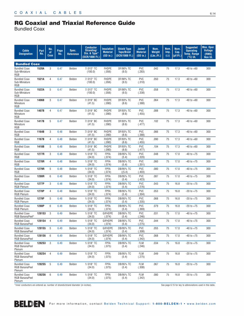
Bundled CoaxBundled Coax 1520A 3 6.47 Belden 7/.012″ TC FHDPE DF/90% TC PVC .042 75 17.3 -40 to +60 300Sub-Miniature (100.0) (.056) (9.5) (.283)RGB Bundled Coax 1521A 4 6.47 Belden 7/.012″ TC FHDPE DF/90% TC PVC .050 75 17.3 -40 to +60 300Sub-Miniature (100.0) (.056) (9.5) (.310)RGB Bundled Coax 1522A 5 6.47 Belden 7/.012″ TC FHDPE DF/90% TC PVC .058 75 17.3 -40 to +60 300Sub-Miniature (100.0) (.056) (9.5) (.338)RGB Bundled Coax 1406B 3 6.47 Belden 7/.019″ BC FHDPE DF/93% TC PVC .064 75 17.3 -40 to +60 300Miniature (41.5) (.090) (8.6) (.388)RGB Bundled Coax 1407B 4 6.47 Belden 7/.019″ BC FHDPE DF/93% TC PVC .088 75 17.3 -40 to +60 300Miniature (41.5) (.090) (8.6) (.455)RGB Bundled Coax 1417B 5 6.47 Belden 7/.019″ BC FHDPE DF/93% TC PVC .102 75 17.3 -40 to +60 300Miniature (41.5) (.090) (8.6) (.477)RGB Bundled Coax 1164B 3 6.48 Belden 7/.019″ BC FHDPE DF/93% TC PVC .066 75 17.3 -40 to +60 300RGB (41.5) (.090) (8.6) (.388)Bundled Coax 1167B 4 6.48 Belden 7/.019″ BC FHDPE DF/93% TC PVC .090 75 17.3 -40 to +60 300RGB (41.5) (.090) (8.6) (.455)Bundled Coax 1418B 5 6.48 Belden 7/.019″ BC FHDPE DF/93% TC PVC .104 75 17.3 -40 to +60 300RGB (41.5) (.090) (8.6) (.477)Bundled Coax 1277R 3 6.48 Belden 1/.018″ TC FPFA DB/95% TC PVC .048 75 17.0 -40 to +75 300RGB (34.0) (.074) (5.4) (.320)Bundled Coax 1278R 4 6.48 Belden 1/.018″ TC FPFA DB/95% TC PVC .060 75 17.0 -40 to +75 300RGB (34.0) (.074) (5.4) (.351)Bundled Coax 1279R 5 6.48 Belden 1/.018″ TC FPFA DB/95% TC PVC .080 75 17.0 -40 to +75 300RGB (34.0) (.074) ((5.4) (.403)Bundled Coax 1280R 6 6.48 Belden 1/.018″ TC FPFA DB/95% TC PVC .087 75 17.0 -40 to +75 300RGB (34.0) (.074) (5.4) (.423)Bundled Coax 1277P 3 6.48 Belden 1/.018″ TC FPFA DB/95% TC PVC .043 75 16.8 -20 to +75 300RGB Plenum (34.0) (.074) (5.4) (.276)Bundled Coax 1278P 4 6.48 Belden 1/.018″ TC FPFA DB/95% TC PVC .053 75 16.8 -20 to +75 300RGB Plenum (34.0) (.074) (5.4) (.304)Bundled Coax 1279P 5 6.48 Belden 1/.018″ TC FPFA DB/95% TC PVC .068 75 16.8 -20 to +75 300RGB Plenum (34.0) (.074) (5.4) (.335)Bundled Coax 1280P 6 6.48 Belden 1/.018″ TC FPFA DB/95% TC PVC .079 75 16.8 -20 to +75 300RGB Plenum (34.0) (.074) (5.4) (.369)Bundled Coax 1281S3 3 6.49 Belden 1/.018″ TC GIFHDPE DB/95% TC PVC .031 75 17.0 -40 to +75 300RGB BananaPeel® (34.0) (.074) (5.4) (.246)Bundled Coax 1281S4 4 6.49 Belden 1/.018″ TC GIFHDPE DB/95% TC PVC .044 75 17.0 -40 to +75 300RGB BananaPeel (34.0) (.074) (5.4) (.275)Bundled Coax 1281S5 5 6.49 Belden 1/.018″ TC GIFHDPE DB/95% TC PVC .055 75 17.0 -40 to +75 300RGB BananaPeel (34.0) (.074) (5.4) (.308)Bundled Coax 1281S6 6 6.49 Belden 1/.018″ TC GIFHDPE DB/95% TC PVC .068 75 17.0 -40 to +75 300RGB BananaPeel (34.0) (.074) (5.4) (.342)Bundled Coax 1282S3 3 6.49 Belden 1/.018″ TC FPFA DB/95% TC FLM .034 75 16.8 -20 to +75 300RGB BananaPeel (34.0) (.075) (5.4) (.246)PlenumBundled Coax 1282S4 4 6.49 Belden 1/.018″ TC FPFA DB/95% TC FLM .049 75 16.8 -20 to +75 300RGB BananaPeel (34.0) (.075) (5.4) (.275)PlenumBundled Coax 1282S5 5 6.49 Belden 1/.018″ TC FPFA DB/95% TC FLM .067 75 16.8 -20 to +75 300RGB BananaPeel (34.0) (.075) (5.4) (.308)PlenumBundled Coax 1282S6 6 6.49 Belden 1/.018″ TC FPFA DB/95% TC FLM .080 75 16.8 -20 to +75 300RGB BananaPeel (34.0) (.075) (5.4) (.342)Plenum*Inner conductors are entered as: number of strands/strand diameter (in inches). See page 6.15 for key to abbreviations used in this table.
RG Coaxial and Triaxial Reference GuideBundled Coax
Nom.Cap.
(pF/Ft.)
Nom.Weight
(Lbs./Ft.)
Shield TypeTape/Braid
(DCR/1000 Ft.)
Nom.Imp.(Ω)
InsulationMaterial(OD in.)
JacketMaterial(OD in.)
ConductorStranding/
Dia. & Type*(DCR/1000 Ft.)
Spec. Reference
Page No.
SuggestedOperating
Temp. Range(°C) UL
Max. Oper.Voltage(RMS)Non UL
Cable Designation
No.of
Coax
PartNo.
Cable Designation
C O A X I A L C A B L E S 6.15
6 •
Coax
ial C
able
s
F o r m o r e i n f o r m a t i o n , c o n t a c t B e l d e n Te c h n i c a l S u p p o r t : 1 - 8 0 0 - B E L D E N - 1 • w w w . b e l d e n . c o m
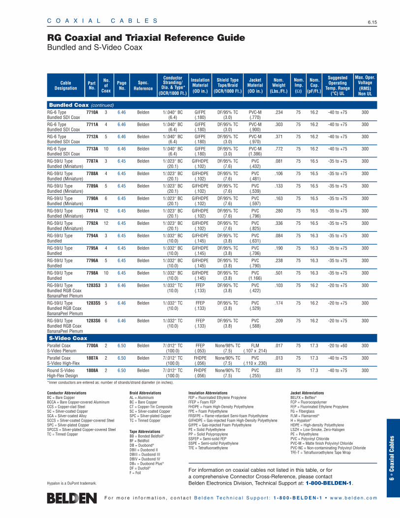
RG Coaxial and Triaxial Reference GuideBundled and S-Video Coax
Nom.Cap.
(pF/Ft.)
Nom.Weight
(Lbs./Ft.)
Shield TypeTape/Braid
(DCR/1000 Ft.)
Nom.Imp.(Ω)
InsulationMaterial(OD in.)
JacketMaterial(OD in.)
ConductorStranding/
Dia. & Type*(DCR/1000 Ft.)
Spec. Reference
Page No.
SuggestedOperating
Temp. Range(°C) UL
Max. Oper.Voltage(RMS)Non UL
Bundled Coax (continued)
RG-6 Type 7710A 3 6.46 Belden 1/.040″ BC GIFPE DF/95% TC PVC-M .234 75 16.2 -40 to +75 300Bundled SDI Coax (6.4) (.180) (3.0) (.770)RG-6 Type 7711A 4 6.46 Belden 1/.040″ BC GIFPE DF/95% TC PVC-M .303 75 16.2 -40 to +75 300Bundled SDI Coax (6.4) (.180) (3.0) (.900)RG-6 Type 7712A 5 6.46 Belden 1/.040″ BC GIFPE DF/95% TC PVC-M .371 75 16.2 -40 to +75 300Bundled SDI Coax (6.4) (.180) (3.0) (.970)RG-6 Type 7713A 10 6.46 Belden 1/.040″ BC GIFPE DF/95% TC PVC-M .772 75 16.2 -40 to +75 300Bundled SDI Coax (6.4) (.180) (3.0) (1.386)
RG-59/U Type 7787A 3 6.45 Belden 1/.023″ BC GIFHDPE DF/95% TC PVC .081 75 16.5 -35 to +75 300Bundled (Miniature) (20.1) (.102) (7.6) (.432)
RG-59/U Type 7788A 4 6.45 Belden 1/.023″ BC GIFHDPE DF/95% TC PVC .106 75 16.5 -35 to +75 300Bundled (Miniature) (20.1) (.102) (7.6) (.481)
RG-59/U Type 7789A 5 6.45 Belden 1/.023″ BC GIFHDPE DF/95% TC PVC .133 75 16.5 -35 to +75 300Bundled (Miniature) (20.1) (.102) (7.6) (.539)
RG-59/U Type 7790A 6 6.45 Belden 1/.023″ BC GIFHDPE DF/95% TC PVC .163 75 16.5 -35 to +75 300Bundled (Miniature) (20.1) (.102) (7.6) (.597)
RG-59/U Type 7791A 12 6.45 Belden 1/.023″ BC GIFHDPE DF/95% TC PVC .280 75 16.5 -35 to +75 300Bundled (Miniature) (20.1) (.102) (7.6) (.796)
RG-59/U Type 7792A 12 6.45 Belden 1/.023″ BC GIFHDPE DF/95% TC PVC .336 75 16.5 -35 to +75 300Bundled (Miniature) (20.1) (.102) (7.6) (.825)
RG-59/U Type 7794A 3 6.45 Belden 1/.032″ BC GIFHDPE DF/95% TC PVC .084 75 16.3 -35 to +75 300Bundled (10.0) (.145) (3.8) (.631)
RG-59/U Type 7795A 4 6.45 Belden 1/.032″ BC GIFHDPE DF/95% TC PVC .190 75 16.3 -35 to +75 300Bundled (10.0) (.145) (3.8) (.706)
RG-59/U Type 7796A 5 6.45 Belden 1/.032″ BC GIFHDPE DF/95% TC PVC .238 75 16.3 -35 to +75 300Bundled (10.0) (.145) (3.8) (.790)
RG-59/U Type 7798A 10 6.45 Belden 1/.032″ BC GIFHDPE DF/95% TC PVC .501 75 16.3 -35 to +75 300Bundled (10.0) (.145) (3.8) (1.166)
RG-59/U Type 1283S3 3 6.46 Belden 1/.032″ TC FFEP DF/95% TC PVC .103 75 16.2 -20 to +75 300Bundled RGB Coax (10.0) (.133) (3.8) (.422)BananaPeel Plenum
RG-59/U Type 1283S5 5 6.46 Belden 1/.032″ TC FFEP DF/95% TC PVC .174 75 16.2 -20 to +75 300Bundled RGB Coax (10.0) (.133) (3.8) (.529)BananaPeel Plenum
RG-59/U Type 1283S6 6 6.46 Belden 1/.032″ TC FFEP DF/95% TC PVC .209 75 16.2 -20 to +75 300Bundled RGB Coax (10.0) (.133) (3.8) (.588)BananaPeel Plenum
S-Video CoaxParallel Coax 7700A 2 6.50 Belden 7/.012″ TC FFEP None/98% TC FLM .017 75 17.3 -20 to +60 300S-Video Plenum (100.0) (.053) (7.5) (.107 x .214)
Parallel Coax 1807A 2 6.50 Belden 7/.012″ TC FHDPE None/90% TC PVC .013 75 17.3 -40 to +75 300S-Video High-Flex (100.0) (.056) (7.5) (.110 x .230)
Round S-Video 1808A 2 6.50 Belden 7/.012″ TC FHDPE None/90% TC PVC .031 75 17.3 -40 to +75 300High-Flex Design (100.0) (.056) (7.5) (.255)*Inner conductors are entered as: number of strands/strand diameter (in inches).
Conductor AbbreviationsBC = Bare CopperBCCA = Bare Copper-covered AluminumCCS = Copper-clad SteelSC = Silver-coated CopperSCA = Silver-coated AlloySCCS = Silver-coated Copper-covered SteelSPC = Silver-plated CopperSPCCS = Silver-plated Copper-covered SteelTC = Tinned Copper
Braid AbbreviationsAL = AluminumBC = Bare CopperCT = Copper-Tin CompositeSC = Silver-coated CopperSPC = Silver-plated CopperTC = Tinned Copper
Tape AbbreviationsBB = Bonded Beldfoil®
BF = BeldfoilDB = Duobond®
DBII = Duobond II DBIII = Duobond III DBIV = Duobond IV DB+ = Duobond Plus®
DF = Duofoil®
F = Foil
Insulation AbbreviationsFEP = Fluorinated Ethylene PropyleneFFEP = Foam FEPFHDPE = Foam High-Density PolyethyleneFPE = Foam PolyethyleneFRSFPE = Flame-retardant Semi-foam PolyethyleneGIFHDPE = Gas-injected Foam High-Density PolyethyleneGIFPE = Gas-injected Foam PolyethylenePE = Solid PolyethylenePP = Solid PolypropyleneSSFEP = Semi-solid FEPSSPE = Semi-solid PolyethyleneTFE = Tetrafluoroethylene
Jacket AbbreviationsBELFX = Belflex®
FCP = FluorocopolymerFEP = Fluorinated Ethylene PropyleneFG = FiberglassFLM = Flamarrest®
H = Hypalon®
HDPE = High-density PolyethyleneLSZH = Low-Smoke, Zero-HalogenPE = PolyethylenePVC = Polyvinyl ChloridePVC-M = Matte finish Polyvinyl ChloridePVC-NC = Non-contaminating Polyvinyl ChlorideTFE-T = Tetrafluoroethylene Tape Wrap
For information on coaxial cables not listed in this table, or for a comprehensive Connector Cross-Reference, please contact Belden Electronics Division, Technical Support at: 1-800-BELDEN-1.Hypalon is a DuPont trademark.
ShieldingMaterialsNom. DCR
Nom.Imp.(Ω)
Nominal Core OD Nominal OD
Inch mm Inch mm
Conductor(stranding)DiameterNom. DCR
StandardUnit WeightStandard Lengths
Lbs. kgFt. m
UL NEC/C(UL) CEC
Type
PartNo.
MHz dB/100 Ft.
dB/100m
Nominal Attenuation
Nominal Capacitance
pF/mpF/Ft.
Nom.Vel.of
Prop.Description
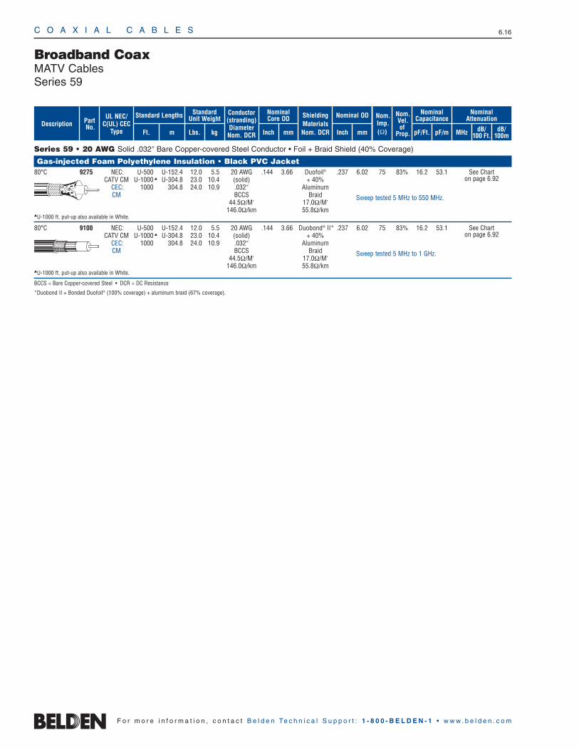
Broadband CoaxMATV CablesSeries 59
C O A X I A L C A B L E S 6.16
F o r m o r e i n f o r m a t i o n , c o n t a c t B e l d e n Te c h n i c a l S u p p o r t : 1 - 8 0 0 - B E L D E N - 1 • w w w . b e l d e n . c o m
Series 59 • 20 AWG Solid .032″ Bare Copper-covered Steel Conductor • Foil + Braid Shield (40% Coverage)
Gas-injected Foam Polyethylene Insulation • Black PVC Jacket80°C 9275 NEC: U-500 U-152.4 12.0 5.5 20 AWG .144 3.66 Duofoil® .237 6.02 75 83% 16.2 53.1
CATV CM U-1000 U-304.8 23.0 10.4 (solid) + 40% CEC: 1000 304.8 24.0 10.9 .032″ AluminumCM BCCS Braid
44.5Ω/M′ 17.0Ω/M′146.0Ω/km 55.8Ω/km
U-1000 ft. put-up also available in White.
80°C 9100 NEC: U-500 U-152.4 12.0 5.5 20 AWG .144 3.66 Duobond® II* .237 6.02 75 83% 16.2 53.1CATV CM U-1000 U-304.8 23.0 10.4 (solid) + 40%
CEC: 1000 304.8 24.0 10.9 .032″ AluminumCM BCCS Braid
44.5Ω/M′ 17.0Ω/M′146.0Ω/km 55.8Ω/km
U-1000 ft. put-up also available in White.
BCCS = Bare Copper-covered Steel • DCR = DC Resistance
*Duobond II = Bonded Duofoil® (100% coverage) + aluminum braid (67% coverage).
See Chart on page 6.92
See Chart on page 6.92
Sweep tested 5 MHz to 550 MHz.
Sweep tested 5 MHz to 1 GHz.

6 •
Coax
ial C
able
s
C O A X I A L C A B L E S 6.17
F o r m o r e i n f o r m a t i o n , c o n t a c t B e l d e n Te c h n i c a l S u p p o r t : 1 - 8 0 0 - B E L D E N - 1 • w w w . b e l d e n . c o m
Series 59 • 20 AWG Solid .032″ Bare Copper-covered Steel Conductor • Duobond® + Aluminum Braid(s) Shield (67% Coverage)
Gas-injected Foam Polyethylene Insulation • Black PVC Jacket80°C 9104 NEC: U-1000 U-304.8 24.0 10.9 20 AWG .144 3.66 Duobond II* .237 6.02 75 83% 16.2 53.1
CATV CM 1000 304.8 24.0 10.9 (solid) + 67% CEC: .032″ AluminumCM BCCS Braid
44.5Ω/M′ 12.0Ω/M′U-1000 ft. put-ups also available in Beige and White. 146.0Ω/km 39.4Ω/km1000 ft. put-up available in Black only.
80°C 9104N — 1000 304.8 24.0 10.9 20 AWG .144 3.66 Duobond II* .237 6.02 75 83% 16.2 53.1(solid) + 67% .032″ AluminumBCCS Braid
44.5Ω/M′ 12.0Ω/M′146.0Ω/km 39.4Ω/km
1000 ft. put-up also available in White.
Plenum • Foam FEP Teflon® Insulation • Natural Flamarrest® Jacket75°C 9104P NEC: 1000 † 304.8 24.0 10.9 20 AWG .140 3.56 Duobond II* .203 5.16 75 83% 16.3 53.5
CATVP CMP (solid) + 67% CEC: .032″ AluminumCMP BCCS Braid
44.5Ω/M′ 12.0Ω/M′146.0Ω/km 39.4Ω/km
Gas-injected Foam High-Density Polyethylene Insulation • Black PVC JacketAerial 9105M 1000 304.8 38.0 17.3 20 AWG .144 3.66 Duobond II* .240 6.10 75 83% 16.2 53.180°C u (solid) + 67% x x
.032″ Aluminum .387 9.83BCCS Braid
44.5Ω/M′ 12.0Ω/M′146.0Ω/km 39.4Ω/km
80°C 9110 NEC: U-1000 U-304.8 24.0 10.9 20 AWG .144 3.66 Duobond III* .242 6.15 75 83% 16.2 53.1CATV CM (solid) + 67%
CEC: .032″ AluminumCM BCCS Braid
44.5Ω/M′ 12.0Ω/M′146.0Ω/km 39.4Ω/km
U-1000 ft. put-up available in White only.
80°C 1186A NEC: 1000 304.8 27.0 12.3 20 AWG .144 3.66 Duobond IV* .265 6.73 75 83% 16.2 53.1CATV CM (solid) + 67% & 46%
CEC: .032″ AluminumCM BCCS Braids
44.5Ω/M′ 7.0Ω/M′146.0Ω/km 23.0Ω/km
BCCS = Bare Copper-covered Steel • DCR = DC Resistance • FEP = Fluorinated Ethylene Propylene
Contact the Belden Customer Service Department for a Comprehensive Connector Cross Reference. 1-800-BELDEN-1.
*Duobond II = Bonded Duofoil® (100% coverage) + aluminum braid (67% coverage).Duobond III = Bonded Duofoil (100% coverage) + aluminum braid (67% coverage) + Duofoil (100% coverage).Duobond IV = Bonded Duofoil (100% coverage) + aluminum braid(67% coverage) + Duofoil (100% coverage) + aluminum braid (46% coverage).
†Spools and/or UnReel® cartons are one piece, but length may vary ±10% for spools and ±5% for UnReel from length shown.
Broadband CoaxCATV CablesSeries 59
1 .4 1.310 .8 2.650 1.8 5.9
100 2.6 8.5200 3.8 12.5400 5.6 18.4700 7.6 24.9900 8.8 28.9
1000 9.4 30.8
See Chart on page 6.92
See Chart on page 6.92
See Chart on page 6.92
See Chart on page 6.92
See Chart on page 6.92
Sweep tested 5 MHz to 1 GHz.
Sweep tested 5 MHz to 1 GHz.
Sweep tested 5 MHz to 1 GHz.
Sweep tested 5 MHz to 1 GHz.
ShieldingMaterialsNom. DCR
Nom.Imp.(Ω)
Nominal Core OD Nominal OD
Inch mm Inch mm
Conductor(stranding)DiameterNom. DCR
StandardUnit WeightStandard Lengths
Lbs. kgFt. m
UL NEC/C(UL) CEC
Type
PartNo.
MHz dB/100 Ft.
dB/100m
Nominal Attenuation
Nominal Capacitance
pF/mpF/Ft.
Nom.Vel.of
Prop.Description
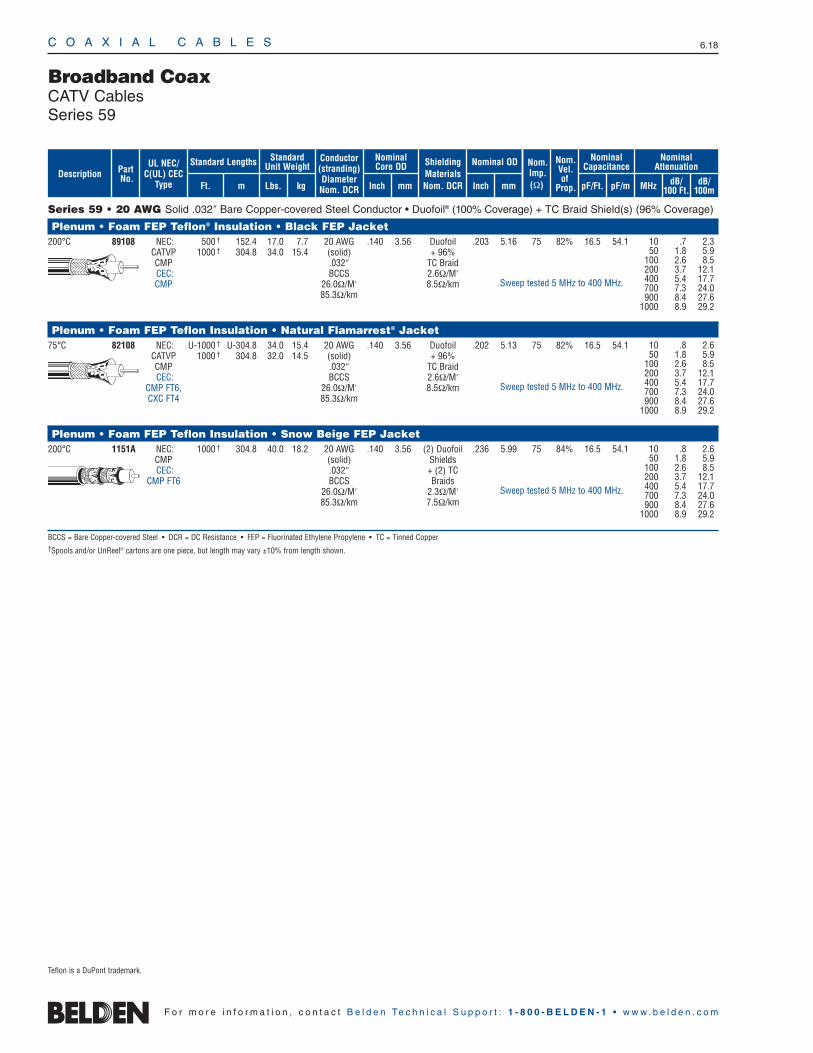
Teflon is a DuPont trademark.
C O A X I A L C A B L E S 6.18
F o r m o r e i n f o r m a t i o n , c o n t a c t B e l d e n Te c h n i c a l S u p p o r t : 1 - 8 0 0 - B E L D E N - 1 • w w w . b e l d e n . c o m
Series 59 • 20 AWG Solid .032″ Bare Copper-covered Steel Conductor • Duofoil® (100% Coverage) + TC Braid Shield(s) (96% Coverage)
Plenum • Foam FEP Teflon® Insulation • Black FEP Jacket 200°C 89108 NEC: 500 † 152.4 17.0 7.7 20 AWG .140 3.56 Duofoil .203 5.16 75 82% 16.5 54.1
CATVP 1000 † 304.8 34.0 15.4 (solid) + 96% CMP .032″ TC BraidCEC: BCCS 2.6Ω/M′CMP 26.0Ω/M′ 8.5Ω/km
85.3Ω/km
Plenum • Foam FEP Teflon Insulation • Natural Flamarrest® Jacket 75°C 82108 NEC: U-1000 † U-304.8 34.0 15.4 20 AWG .140 3.56 Duofoil .202 5.13 75 82% 16.5 54.1
CATVP 1000 † 304.8 32.0 14.5 (solid) + 96% CMP .032″ TC BraidCEC: BCCS 2.6Ω/M′
CMP FT6, 26.0Ω/M′ 8.5Ω/kmCXC FT4 85.3Ω/km
Plenum • Foam FEP Teflon Insulation • Snow Beige FEP Jacket 200°C 1151A NEC: 1000 † 304.8 40.0 18.2 20 AWG .140 3.56 (2) Duofoil .236 5.99 75 84% 16.5 54.1
CMP (solid) ShieldsCEC: .032″ + (2) TC
CMP FT6 BCCS Braids26.0Ω/M′ 2.3Ω/M′85.3Ω/km 7.5Ω/km
BCCS = Bare Copper-covered Steel • DCR = DC Resistance • FEP = Fluorinated Ethylene Propylene • TC = Tinned Copper†Spools and/or UnReel® cartons are one piece, but length may vary ±10% from length shown.
Broadband CoaxCATV CablesSeries 59
10 .8 2.650 1.8 5.9
100 2.6 8.5200 3.7 12.1400 5.4 17.7700 7.3 24.0900 8.4 27.6
1000 8.9 29.2
10 .8 2.650 1.8 5.9
100 2.6 8.5200 3.7 12.1400 5.4 17.7700 7.3 24.0900 8.4 27.6
1000 8.9 29.2
Sweep tested 5 MHz to 400 MHz.
Sweep tested 5 MHz to 400 MHz.
Sweep tested 5 MHz to 400 MHz.
10 .7 2.350 1.8 5.9
100 2.6 8.5200 3.7 12.1400 5.4 17.7700 7.3 24.0900 8.4 27.6
1000 8.9 29.2
ShieldingMaterialsNom. DCR
Nom.Imp.(Ω)
Nominal Core OD Nominal OD
Inch mm Inch mm
Conductor(stranding)DiameterNom. DCR
StandardUnit WeightStandard Lengths
Lbs. kgFt. m
UL NEC/C(UL) CEC
Type
PartNo.
MHz dB/100 Ft.
dB/100m
Nominal Attenuation
Nominal Capacitance
pF/mpF/Ft.
Nom.Vel.of
Prop.Description
Teflon is a DuPont trademark.
C O A X I A L C A B L E S 6.19
6 •
Coax
ial C
able
s
F o r m o r e i n f o r m a t i o n , c o n t a c t B e l d e n Te c h n i c a l S u p p o r t : 1 - 8 0 0 - B E L D E N - 1 • w w w . b e l d e n . c o m
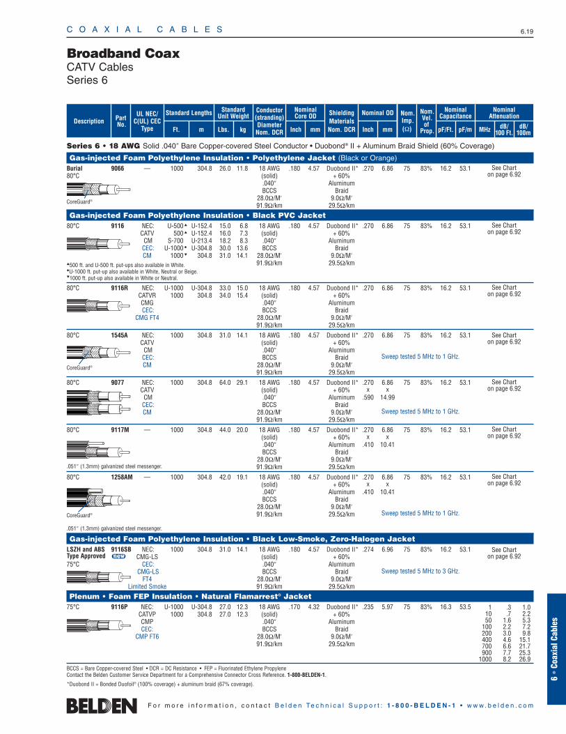
Series 6 • 18 AWG Solid .040″ Bare Copper-covered Steel Conductor • Duobond® II + Aluminum Braid Shield (60% Coverage)
Gas-injected Foam Polyethylene Insulation • Polyethylene Jacket (Black or Orange)Burial 9066 — 1000 304.8 26.0 11.8 18 AWG .180 4.57 Duobond II* .270 6.86 75 83% 16.2 53.180°C (solid) + 60%
.040″ AluminumBCCS Braid
28.0Ω/M′ 9.0Ω/M′91.9Ω/km 29.5Ω/km
Gas-injected Foam Polyethylene Insulation • Black PVC Jacket80°C 9116 NEC: U-500 U-152.4 15.0 6.8 18 AWG .180 4.57 Duobond II* .270 6.86 75 83% 16.2 53.1
CATV 500 U-152.4 16.0 7.3 (solid) + 60% CM S-700 U-213.4 18.2 8.3 .040″ Aluminum
CEC: U-1000 U-304.8 30.0 13.6 BCCS BraidCM 1000 304.8 31.0 14.1 28.0Ω/M′ 9.0Ω/M′
500 ft. and U-500 ft. put-ups also available in White. 91.9Ω/km 29.5Ω/kmU-1000 ft. put-up also available in White, Neutral or Beige. 1000 ft. put-up also available in White or Neutral.
80°C 9116R NEC: U-1000 U-304.8 33.0 15.0 18 AWG .180 4.57 Duobond II* .270 6.86 75 83% 16.2 53.1CATVR 1000 304.8 34.0 15.4 (solid) + 60% CMG .040″ AluminumCEC: BCCS Braid
CMG FT4 28.0Ω/M′ 9.0Ω/M′91.9Ω/km 29.5Ω/km
80°C 1545A NEC: 1000 304.8 31.0 14.1 18 AWG .180 4.57 Duobond II* .270 6.86 75 83% 16.2 53.1CATV (solid) + 60%
CM .040″ AluminumCEC: BCCS BraidCM 28.0Ω/M′ 9.0Ω/M′
91.9Ω/km 29.5Ω/km
80°C 9077 NEC: 1000 304.8 64.0 29.1 18 AWG .180 4.57 Duobond II* .270 6.86 75 83% 16.2 53.1CATV (solid) + 60% x x
CM .040″ Aluminum .590 14.99CEC: BCCS BraidCM 28.0Ω/M′ 9.0Ω/M′
91.9Ω/km 29.5Ω/km
80°C 9117M — 1000 304.8 44.0 20.0 18 AWG .180 4.57 Duobond II* .270 6.86 75 83% 16.2 53.1(solid) + 60% x x.040″ Aluminum .410 10.41BCCS Braid
28.0Ω/M′ 9.0Ω/M′.051″ (1.3mm) galvanized steel messenger. 91.9Ω/km 29.5Ω/km
80°C 1258AM — 1000 304.8 42.0 19.1 18 AWG .180 4.57 Duobond II* .270 6.86 75 83% 16.2 53.1(solid) + 60% x x.040″ Aluminum .410 10.41BCCS Braid
28.0Ω/M′ 9.0Ω/M′91.9Ω/km 29.5Ω/km
.051″ (1.3mm) galvanized steel messenger.
Gas-injected Foam Polyethylene Insulation • Black Low-Smoke, Zero-Halogen JacketLSZH and ABS 9116SB NEC: 1000 304.8 31.0 14.1 18 AWG .180 4.57 Duobond II* .274 6.96 75 83% 16.2 53.1Type Approved u CMG-LS (solid) + 60% 75°C CEC: .040″ Aluminum
CMG-LS BCCS BraidFT4 28.0Ω/M′ 9.0Ω/M′
Limited Smoke 91.9Ω/km 29.5Ω/km
Plenum • Foam FEP Insulation • Natural Flamarrest® Jacket75°C 9116P NEC: U-1000 U-304.8 27.0 12.3 18 AWG .170 4.32 Duobond II* .235 5.97 75 83% 16.3 53.5
CATVP 1000 304.8 27.0 12.3 (solid) + 60% CMP .040″ AluminumCEC: BCCS Braid
CMP FT6 28.0Ω/M′ 9.0Ω/M′91.9Ω/km 29.5Ω/km
BCCS = Bare Copper-covered Steel • DCR = DC Resistance • FEP = Fluorinated Ethylene PropyleneContact the Belden Customer Service Department for a Comprehensive Connector Cross Reference. 1-800-BELDEN-1.
*Duobond II = Bonded Duofoil® (100% coverage) + aluminum braid (67% coverage).
Broadband CoaxCATV CablesSeries 6
See Chart on page 6.92
See Chart on page 6.92
See Chart on page 6.92
See Chart on page 6.92
See Chart on page 6.92
See Chart on page 6.92
CoreGuard®
CoreGuard®
Sweep tested 5 MHz to 1 GHz.
Sweep tested 5 MHz to 1 GHz.
Sweep tested 5 MHz to 1 GHz.
See Chart on page 6.92
Sweep tested 5 MHz to 3 GHz.
See Chart on page 6.92
CoreGuard®
1 .3 1.010 .7 2.250 1.6 5.3
100 2.2 7.2200 3.0 9.8400 4.6 15.1700 6.6 21.7900 7.7 25.3
1000 8.2 26.9
ShieldingMaterialsNom. DCR
Nom.Imp.(Ω)
Nominal Core OD Nominal OD
Inch mm Inch mm
Conductor(stranding)DiameterNom. DCR
StandardUnit WeightStandard Lengths
Lbs. kgFt. m
UL NEC/C(UL) CEC
Type
PartNo.
MHz dB/100 Ft.
dB/100m
Nominal Attenuation
Nominal Capacitance
pF/mpF/Ft.
Nom.Vel.of
Prop.Description
C O A X I A L C A B L E S 6.20
F o r m o r e i n f o r m a t i o n , c o n t a c t B e l d e n Te c h n i c a l S u p p o r t : 1 - 8 0 0 - B E L D E N - 1 • w w w . b e l d e n . c o m
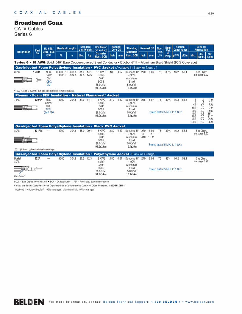
Series 6 • 18 AWG Solid .040″ Bare Copper-covered Steel Conductor • Duobond® II + Aluminum Braid Shield (90% Coverage)
Gas-injected Foam Polyethylene Insulation • PVC Jacket (Available in Black or Neutral)80°C 1530A NEC: U-1000 U-304.8 31.0 14.1 18 AWG .180 4.57 Duobond II* .270 6.86 75 83% 16.2 53.1
CATV 1000 304.8 32.0 14.5 (solid) + 90% CM .040″ AluminumCEC: BCCS BraidCM 28.0Ω/M′ 5.0Ω/M′
91.9Ω/km 16.4Ω/km1000 ft. and U-1000 ft. put-ups also available in White Neutral.
Plenum • Foam FEP Insulation • Natural Flamarrest® Jacket75°C 1530AP NEC: 1000 304.8 31.0 14.1 18 AWG .170 4.32 Duobond II* .235 5.97 75 83% 16.3 53.5
CATVP (solid) + 90% CMP .040″ AluminumCEC: BCCS Braid
CMP FT6 28.0Ω/M′ 5.0Ω/M′91.9Ω/km 16.4Ω/km
Gas-injected Foam Polyethylene Insulation • Black PVC Jacket80°C 1531AM — 1000 304.8 45.0 20.4 18 AWG .180 4.57 Duobond II* .270 6.86 75 83% 16.2 53.1
(solid) + 90% x x.040″ Aluminum .410 10.41BCCS Braid
28.0Ω/M′ 5.0Ω/M′91.9Ω/km 16.4Ω/km
.051″ (1.3mm) galvanized steel messenger.
Gas-injected Foam Polyethylene Insulation • Polyethylene Jacket (Black or Orange)Burial 1532A — 1000 304.8 27.0 12.3 18 AWG .180 4.57 Duobond II* .270 6.86 75 83% 16.2 53.180°C (solid) + 90%
.040″ AluminumBCCS Braid
28.0Ω/M′ 5.0Ω/M′91.9Ω/km 16.4Ω/km
BCCS = Bare Copper-covered Steel • DCR = DC Resistance • FEP = Fluorinated Ethylene Propylene
Contact the Belden Customer Service Department for a Comprehensive Connector Cross Reference. 1-800-BELDEN-1.
*Duobond II = Bonded Duofoil® (100% coverage) + aluminum braid (67% coverage).
Broadband CoaxCATV CablesSeries 6
1 .3 1.010 .7 2.350 1.6 5.3
100 2.2 7.2200 3.0 9.8400 4.6 15.1700 6.6 21.7900 7.7 25.3
1000 8.2 26.9
See Chart on page 6.92
See Chart on page 6.92
See Chart on page 6.92
CoreGuard®
Sweep tested 5 MHz to 1 GHz.
Sweep tested 5 MHz to 1 GHz.
Sweep tested 5 MHz to 1 GHz.
ShieldingMaterialsNom. DCR
Nom.Imp.(Ω)
Nominal Core OD Nominal OD
Inch mm Inch mm
Conductor(stranding)DiameterNom. DCR
StandardUnit WeightStandard Lengths
Lbs. kgFt. m
UL NEC/C(UL) CEC
Type
PartNo.
MHz dB/100 Ft.
dB/100m
Nominal Attenuation
Nominal Capacitance
pF/mpF/Ft.
Nom.Vel.of
Prop.Description

C O A X I A L C A B L E S 6.21
6 •
Coax
ial C
able
s
F o r m o r e i n f o r m a t i o n , c o n t a c t B e l d e n Te c h n i c a l S u p p o r t : 1 - 8 0 0 - B E L D E N - 1 • w w w . b e l d e n . c o m
Series 6 • 18 AWG Solid .040″ Bare Copper-covered Steel Conductor • Duobond® III + Aluminum Braid Shield (60% Coverage)
Gas-injected Foam Polyethylene Insulation • Black PVC Jacket80°C 9118 NEC: U-1000 U-304.8 30.0 13.6 18 AWG .180 4.57 Duobond III* .278 7.06 75 83% 16.2 53.1
CATV 1000 304.8 30.0 13.6 (solid) + 60% CM .040″ AluminumCEC: BCCS BraidCM 28.0Ω/M′ 6.5Ω/M′
91.9Ω/km 21.3Ω/kmU-1000 ft. put-up also available in Beige, White and White Neutral.
80°C 9119M — 1000 304.8 43.0 19.5 18 AWG .180 4.57 Duobond III* .275 6.99 75 83% 16.2 53.1(solid) + 60% x x.040″ Aluminum .416 10.57BCCS Braid
28.0Ω/M′ 6.5Ω/M′91.9Ω/km 21.3Ω/km
.051″ (1.3mm) galvanized steel messenger.
80°C 1546A NEC: U-1000 U-304.8 31.0 14.1 18 AWG .180 4.57 Duobond III* .278 7.06 75 83% 16.2 53.1CATV (solid) + 60% CM .040″ AluminumCEC: BCCS BraidCM 28.0Ω/M′ 6.5Ω/M′
91.9Ω/km 21.3Ω/km
Gas-injected Foam Polyethylene Insulation • Polyethylene Jacket (Black or Orange)Burial 1837A — 1000 304.8 26.0 11.8 18 AWG .180 4.57 Duobond III* .275 6.99 75 83% 16.2 53.180°C (solid) + 60%
.040″ AluminumBCCS Braid
28.0Ω/M′ 6.5Ω/M′91.9Ω/km 21.3Ω/km
Series 6 • 18 AWG Solid .040″ Bare Copper-covered Steel Conductor • Bonded Beldfoil® + Aluminum Braid Shield (50% Coverage)
Gas-injected Foam Polyethylene Insulation • Black PVC Jacket80°C 5339G5 NEC: U-1000 U-304.8 24.0 10.9 18 AWG .180 4.57 Bonded .253 6.43 75 83% 16.2 53.1
u CATV, 1000 304.8 24.0 10.9 (solid) Beldfoil CMG .040″ + 50%CEC: BCCS AL Braid
CMG FT4 28.0Ω/M′ 15.0Ω/M′91.9Ω/km 49.2Ω/km
AL = Aluminum • BCCS = Bare Copper-covered Steel • DCR = DC Resistance
Contact the Belden Customer Service Department for a Comprehensive Connector Cross Reference. 1-800-BELDEN-1.
*Duobond III = Bonded Duofoil® (100% coverage) + aluminum braid (67% coverage) + Duofoil (100% coverage).
Broadband CoaxCATV CablesSeries 6
CoreGuard®
CoreGuard®
See Chart on page 6.92
See Chart on page 6.92
See Chart on page 6.92
See Chart on page 6.92
Sweep tested 5 MHz to 1 GHz.
Sweep tested 5 MHz to 1 GHz.
Sweep tested 5 MHz to 1 GHz.
See Chart on page 6.92
Sweep tested 5 MHz to 3 GHz.
ShieldingMaterialsNom. DCR
Nom.Imp.(Ω)
Nominal Core OD Nominal OD
Inch mm Inch mm
Conductor(stranding)DiameterNom. DCR
StandardUnit WeightStandard Lengths
Lbs. kgFt. m
UL NEC/C(UL) CEC
Type
PartNo.
MHz dB/100 Ft.
dB/100m
Nominal Attenuation
Nominal Capacitance
pF/mpF/Ft.
Nom.Vel.of
Prop.Description
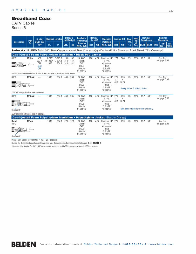
C O A X I A L C A B L E S 6.22
F o r m o r e i n f o r m a t i o n , c o n t a c t B e l d e n Te c h n i c a l S u p p o r t : 1 - 8 0 0 - B E L D E N - 1 • w w w . b e l d e n . c o m
Series 6 • 18 AWG Solid .040″ Bare Copper-covered Steel Conductor(s) • Duobond® III + Aluminum Braid Shield (77% Coverage)
Gas-injected Foam Polyethylene Insulation • Black PVC Jacket80°C 1613A NEC: B-700 B-213.0 19.6 8.9 18 AWG .180 4.57 Duobond III* .278 7.06 75 83% 16.2 53.1
CATV U-1000 U-304.8 31.0 14.1 (solid) + 77% CM 1000 304.8 31.0 14.1 .040″ AluminumCEC: BCCS BraidCM 28.0Ω/M′ 5.6Ω/M′
91.9Ω/km 18.4Ω/kmB-700 also available in White. U-1000 ft. also available in White and White Neutral.
80°C 1615AM — 1000 304.8 44.0 20.0 18 AWG .180 4.57 Duobond III* .275 6.99 75 83% 16.2 53.1(solid) + 77% x x.040″ Aluminum .416 10.57BCCS Braid
28.0Ω/M′ 5.6Ω/M′91.9Ω/km 18.4Ω/km
.051″ (1.3mm) galvanized steel messenger.
80°C 1616AM — 1000 304.8 45.0 20.4 18 AWG .180 4.57 Duobond III* .275 6.99 75 83% 16.2 53.1(solid) + 77% x x.040″ Aluminum .416 10.57BCCS Braid
28.0Ω/M′ 5.6Ω/M′91.9Ω/km 18.4Ω/km
.051″ (1.3mm) galvanized steel messenger.
Gas-injected Foam Polyethylene Insulation • Polyethylene Jacket (Black or Orange)Burial 1614A — 1000 304.8 27.0 12.3 18 AWG .180 4.57 Duobond III* .275 6.99 75 83% 16.2 53.180°C (solid) + 77%
.040″ AluminumBCCS Braid
28.0Ω/M′ 5.6Ω/M′91.9Ω/km 18.4Ω/km
BCCS = Bare Copper-covered Steel • DCR = DC Resistance
Contact the Belden Customer Service Department for a Comprehensive Connector Cross Reference. 1-800-BELDEN-1.
*Duobond III = Bonded Duofoil® (100% coverage) + aluminum braid (67% coverage) + Duofoil (100% coverage).
Broadband CoaxCATV CablesSeries 6
CoreGuard®
CoreGuard®
See Chart on page 6.92
See Chart on page 6.92
See Chart on page 6.92
See Chart on page 6.92
Sweep tested 5 MHz to 1 GHz.
Min. bend radius for minor axis only.
ShieldingMaterialsNom. DCR
Nom.Imp.(Ω)
Nominal Core OD Nominal OD
Inch mm Inch mm
Conductor(stranding)DiameterNom. DCR
StandardUnit WeightStandard Lengths
Lbs. kgFt. m
UL NEC/C(UL) CEC
Type
PartNo.
MHz dB/100 Ft.
dB/100m
Nominal Attenuation
Nominal Capacitance
pF/mpF/Ft.
Nom.Vel.of
Prop.Description

C O A X I A L C A B L E S 6.23
6 •
Coax
ial C
able
s
F o r m o r e i n f o r m a t i o n , c o n t a c t B e l d e n Te c h n i c a l S u p p o r t : 1 - 8 0 0 - B E L D E N - 1 • w w w . b e l d e n . c o m
Series 6 • 18 AWG Solid .040″ Bare Copper-covered Steel Conductor(s) • Duobond Plus® + Aluminum Braid Shield (77% Coverage)
Gas-injected Foam Polyethylene Insulation • Black PVC Jacket80°C 9058 NEC: U-1000 U-304.8 32.0 14.5 18 AWG .180 4.57 Duobond Plus* .275 6.99 75 83% 16.2 53.1
CATV 1000 304.8 31.0 14.1 (solid) + 77% CM .040″ AluminumCEC: BCCS BraidCM 28.0Ω/M′ 5.6Ω/M′
91.9Ω/km 18.4Ω/kmU-1000 ft. put-up also available in White or Beige.
Aerial 9059M — 1000 304.8 43.0 19.5 18 AWG .180 4.57 Duobond Plus* .275 6.99 75 83% 16.2 53.180°C u (solid) + 77% x x
.040″ Aluminum .416 10.57BCCS Braid
28.0Ω/M′ 5.6Ω/M′91.9Ω/km 18.4Ω/km
.051″ (1.3mm) galvanized steel messenger.
80°C 1260AM — 1000 304.8 44.0 20.0 18 AWG .180 4.57 Duobond Plus* .275 6.99 75 83% 16.2 53.1(solid) + 77% x x.040″ Aluminum .416 10.57BCCS Braid
28.0Ω/M′ 5.6Ω/M′91.9Ω/km 18.4Ω/km
.051″ (1.3mm) galvanized steel messenger.
Gas-injected Foam Polyethylene Insulation • PVC Jacket (Available in Black or Orange)Burial 9062 — 1000 304.8 27.0 12.3 18 AWG .180 4.57 Duobond Plus* .275 6.99 75 83% 16.2 53.180°C (solid) + 77%
.040″ AluminumBCCS Braid
28.0Ω/M′ 5.6Ω/M′91.9Ω/km 18.4Ω/km
BCCS = Bare Copper-covered Steel • DCR = DC Resistance
Contact the Belden Customer Service Department for a Comprehensive Connector Cross Reference. 1-800-BELDEN-1.
*Duobond Plus = Bonded Duofoil® (100% coverage) + aluminum braid (67% coverage) + shorting fold.
Broadband CoaxCATV CablesSeries 6
Shorting Fold
Shorting Fold CoreGuard
Shorting Fold CoreGuard
Shorting Fold CoreGuard®
See Chart on page 6.92
See Chart on page 6.92
See Chart on page 6.92
Sweep tested 5 MHz to 1 GHz.
Sweep tested 5 MHz to 1 GHz.
See Chart on page 6.92
Sweep tested 5 MHz to 1 GHz.
Sweep tested 5 MHz to 1 GHz.
ShieldingMaterialsNom. DCR
Nom.Imp.(Ω)
Nominal Core OD Nominal OD
Inch mm Inch mm
Conductor(stranding)DiameterNom. DCR
StandardUnit WeightStandard Lengths
Lbs. kgFt. m
UL NEC/C(UL) CEC
Type
PartNo.
MHz dB/100 Ft.
dB/100m
Nominal Attenuation
Nominal Capacitance
pF/mpF/Ft.
Nom.Vel.of
Prop.Description
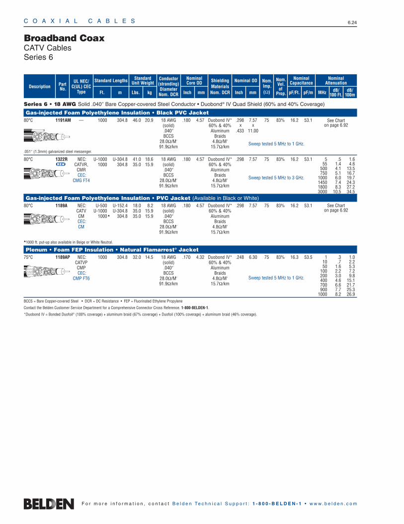
Series 6 • 18 AWG Solid .040″ Bare Copper-covered Steel Conductor • Duobond® IV Quad Shield (60% and 40% Coverage)
Gas-injected Foam Polyethylene Insulation • Black PVC Jacket80°C 1191AM — 1000 304.8 46.0 20.9 18 AWG .180 4.57 Duobond IV* .298 7.57 75 83% 16.2 53.1
(solid) 60% & 40% x x.040″ Aluminum .433 11.00BCCS Braids
28.0Ω/M′ 4.8Ω/M′91.9Ω/km 15.7Ω/km
.051″ (1.3mm) galvanized steel messenger.
80°C 1322R NEC: U-1000 U-304.8 41.0 18.6 18 AWG .180 4.57 Duobond IV* .298 7.57 75 83% 16.2 53.1U CATVR, 1000 304.8 35.0 15.9 (solid) 60% & 40%
CMR .040″ AluminumCEC: BCCS Braids
CMG FT4 28.0Ω/M′ 4.8Ω/M′91.9Ω/km 15.7Ω/km
Gas-injected Foam Polyethylene Insulation • PVC Jacket (Available in Black or White)80°C 1189A NEC: U-500 U-152.4 18.0 8.2 18 AWG .180 4.57 Duobond IV* .298 7.57 75 83% 16.2 53.1
CATV U-1000 U-304.8 35.0 15.9 (solid) 60% & 40%CM 1000 304.8 35.0 15.9 .040″ AluminumCEC: BCCS BraidsCM 28.0Ω/M′ 4.8Ω/M′
91.9Ω/km 15.7Ω/km
1000 ft. put-up also available in Beige or White Neutral.
Plenum • Foam FEP Insulation • Natural Flamarrest® Jacket75°C 1189AP NEC: 1000 304.8 32.0 14.5 18 AWG .170 4.32 Duobond IV* .248 6.30 75 83% 16.3 53.5
CATVP (solid) 60% & 40%CMP .040″ AluminumCEC: BCCS Braids
CMP FT6 28.0Ω/M′ 4.8Ω/M′91.9Ω/km 15.7Ω/km
BCCS = Bare Copper-covered Steel • DCR = DC Resistance • FEP = Fluorinated Ethylene Propylene
Contact the Belden Customer Service Department for a Comprehensive Connector Cross Reference. 1-800-BELDEN-1.
*Duobond IV = Bonded Duofoil® (100% coverage) + aluminum braid (67% coverage) + Duofoil (100% coverage) + aluminum braid (46% coverage).
C O A X I A L C A B L E S 6.24
F o r m o r e i n f o r m a t i o n , c o n t a c t B e l d e n Te c h n i c a l S u p p o r t : 1 - 8 0 0 - B E L D E N - 1 • w w w . b e l d e n . c o m
Sweep tested 5 MHz to 1 GHz.
Broadband CoaxCATV CablesSeries 6
See Chart on page 6.92
See Chart on page 6.92
Sweep tested 5 MHz to 1 GHz.
Sweep tested 5 MHz to 3 GHz.
ShieldingMaterialsNom. DCR
Nom.Imp.(Ω)
Nominal Core OD Nominal OD
Inch mm Inch mm
Conductor(stranding)DiameterNom. DCR
StandardUnit WeightStandard Lengths
Lbs. kgFt. m
UL NEC/C(UL) CEC
Type
PartNo.
MHz dB/100 Ft.
dB/100m
Nominal Attenuation
Nominal Capacitance
pF/mpF/Ft.
Nom.Vel.of
Prop.Description
5 .5 1.655 1.4 4.6
500 4.1 13.5750 5.1 16.7
1000 6.0 19.71450 7.4 24.31800 8.3 27.23000 10.5 34.5
1 .3 1.010 .7 2.250 1.6 5.3
100 2.2 7.2200 3.0 9.8400 4.6 15.1700 6.6 21.7900 7.7 25.3
1000 8.2 26.9
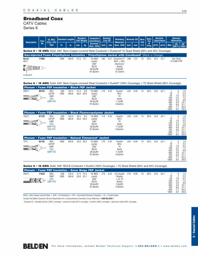
C O A X I A L C A B L E S 6.25
6 •
Coax
ial C
able
s
F o r m o r e i n f o r m a t i o n , c o n t a c t B e l d e n Te c h n i c a l S u p p o r t : 1 - 8 0 0 - B E L D E N - 1 • w w w . b e l d e n . c o m
Series 6 • 18 AWG Solid .040″ Bare Copper-covered Steel Conductor • Duobond® IV Quad Shield (60% and 40% Coverage)
Gas-injected Foam Polyethylene Insulation • Polyethylene Jacket with CoreGuard® (Black or Orange)Burial 1190A — 1000 304.8 31.0 14.1 18 AWG .180 4.57 Duobond IV* .298 7.57 75 83% 16.2 53.180°C (solid) 60% + 40%
.040″ AluminumBCCS Braids
28.0Ω/M′ 4.8Ω/M′91.9Ω/km 15.7Ω/km
Series 6 • 18 AWG Solid .040″ Bare Copper-covered Steel Conductor • Duofoil® (100% Coverage) + TC Braid Shield (95% Coverage)
Plenum • Foam FEP Insulation • Black FEP Jacket200°C 89120 NEC: 500 152.4 21.5 9.8 18 AWG .170 4.32 Duofoil .234 5.94 75 82% 16.5 54.1
CATVP 1000 304.8 46.0 20.9 (solid) 95%CMP .040″ TCCEC: BCCS Braid
CMP FT6 28.0Ω/M′ 1.7Ω/M′91.9Ω/km 5.6Ω/km
Plenum • Foam FEP Insulation • Black Fluorocopolymer Jacket150°C 87120 NEC: 500 152.4 20.5 9.3 18 AWG .170 4.32 Duofoil .234 5.94 75 82% 16.5 54.1
CATVP 1000 304.8 45.0 20.4 (solid) 95%CMP .040″ TCCEC: BCCS Braid
CMP FT6, 28.0Ω/M′ 1.7Ω/M′CXC FT4 91.9Ω/km 5.6Ω/km
Plenum • Foam FEP Insulation • Natural Flamarrest® Jacket75°C 82120 NEC: 1000 304.8 44.0 20.0 18 AWG .170 4.32 Duofoil .234 5.94 75 82% 16.5 54.1
CATVP (solid) 95%CMP .040″ TCCEC: BCCS Braid
CMP FT6 28.0Ω/M′ 1.7Ω/M′91.9Ω/km 5.6Ω/km
Series 6 • 18 AWG Solid .040″ BCCS Conductor • Duofoil (100% Coverage) + TC Braid Shield (60% and 40% Coverage)
Plenum • Foam FEP Insulation • Snow Beige FEP Jacket200°C 1152A NEC: 500 152.4 27.5 12.5 18 AWG .170 4.32 (2) Duofoil .273 6.93 75 82% 16.5 54.1
CMP 1000 304.8 53.0 24.1 (solid) ShieldsCEC: .040″ + (2) TC
CMP FT6 BCCS Braids28.0Ω/M′ 1.8Ω/M′91.9Ω/km 5.9Ω/km
BCCS = Bare Copper-covered Steel • DCR = DC Resistance • FEP = Fluorinated Ethylene Propylene • TC = Tinned Copper
Contact the Belden Customer Service Department for a Comprehensive Connector Cross Reference. 1-800-BELDEN-1.
*Duobond IV = Bonded Duofoil (100% coverage) + aluminum braid (67% coverage) + Duofoil (100% coverage) + aluminum braid (46% coverage).
Broadband CoaxCATV CablesSeries 6
1 .3 1.010 .7 2.250 1.6 5.3
100 2.2 7.2200 3.0 9.8400 4.6 15.1700 6.6 21.7900 7.7 25.3
1000 8.2 26.9
1 .3 1.010 .7 2.250 1.6 5.3
100 2.2 7.2200 3.0 9.8400 4.6 15.1700 6.6 21.7900 7.7 25.3
1000 8.2 26.9
1 .3 1.010 .7 2.250 1.6 5.3
100 2.2 7.2200 3.0 9.8400 4.6 15.1700 6.6 21.7900 7.7 25.3
1000 8.2 26.9
1 .3 1.010 .7 2.250 1.6 5.3
100 2.2 7.2200 3.0 9.8400 4.6 15.1700 6.6 21.7900 7.7 25.3
1000 8.2 26.9
See Chart on page 6.92
CoreGuard®
ShieldingMaterialsNom. DCR
Nom.Imp.(Ω)
Nominal Core OD Nominal OD
Inch mm Inch mm
Conductor(stranding)DiameterNom. DCR
StandardUnit WeightStandard Lengths
Lbs. kgFt. m
UL NEC/C(UL) CEC
Type
PartNo.
MHz dB/100 Ft.
dB/100m
Nominal Attenuation
Nominal Capacitance
pF/mpF/Ft.
Nom.Vel.of
Prop.Description
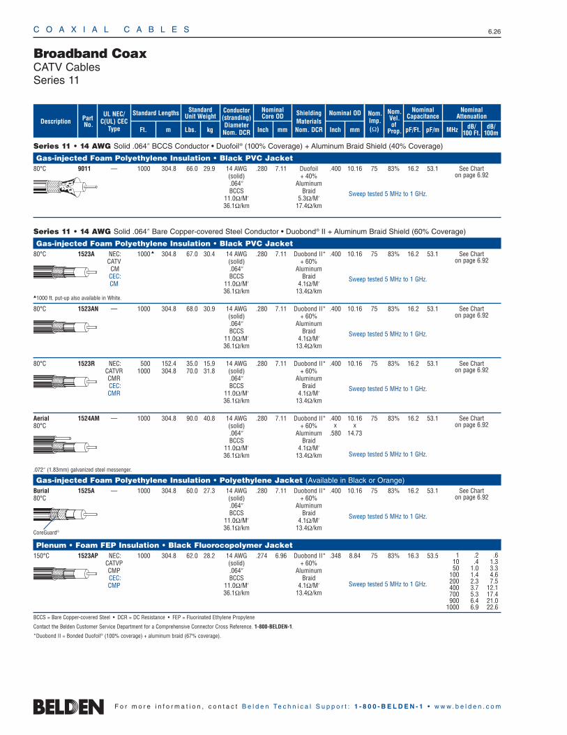
C O A X I A L C A B L E S 6.26
F o r m o r e i n f o r m a t i o n , c o n t a c t B e l d e n Te c h n i c a l S u p p o r t : 1 - 8 0 0 - B E L D E N - 1 • w w w . b e l d e n . c o m
Series 11 • 14 AWG Solid .064″ BCCS Conductor • Duofoil® (100% Coverage) + Aluminum Braid Shield (40% Coverage)
Gas-injected Foam Polyethylene Insulation • Black PVC Jacket80°C 9011 — 1000 304.8 66.0 29.9 14 AWG .280 7.11 Duofoil .400 10.16 75 83% 16.2 53.1
(solid) + 40% .064″ AluminumBCCS Braid
11.0Ω/M′ 5.3Ω/M′36.1Ω/km 17.4Ω/km
Series 11 • 14 AWG Solid .064″ Bare Copper-covered Steel Conductor • Duobond® II + Aluminum Braid Shield (60% Coverage)
Gas-injected Foam Polyethylene Insulation • Black PVC Jacket80°C 1523A NEC: 1000 304.8 67.0 30.4 14 AWG .280 7.11 Duobond II* .400 10.16 75 83% 16.2 53.1
CATV (solid) + 60% CM .064″ Aluminum
CEC: BCCS BraidCM 11.0Ω/M′ 4.1Ω/M′
36.1Ω/km 13.4Ω/km1000 ft. put-up also available in White.
80°C 1523AN — 1000 304.8 68.0 30.9 14 AWG .280 7.11 Duobond II* .400 10.16 75 83% 16.2 53.1(solid) + 60%.064″ AluminumBCCS Braid
11.0Ω/M′ 4.1Ω/M′36.1Ω/km 13.4Ω/km
80°C 1523R NEC: 500 152.4 35.0 15.9 14 AWG .280 7.11 Duobond II* .400 10.16 75 83% 16.2 53.1CATVR 1000 304.8 70.0 31.8 (solid) + 60%CMR .064″ AluminumCEC: BCCS BraidCMR 11.0Ω/M′ 4.1Ω/M′
36.1Ω/km 13.4Ω/km
Aerial 1524AM — 1000 304.8 90.0 40.8 14 AWG .280 7.11 Duobond II* .400 10.16 75 83% 16.2 53.180°C (solid) + 60% x x
.064″ Aluminum .580 14.73BCCS Braid
11.0Ω/M′ 4.1Ω/M′36.1Ω/km 13.4Ω/km
.072″ (1.83mm) galvanized steel messenger.
Gas-injected Foam Polyethylene Insulation • Polyethylene Jacket (Available in Black or Orange)Burial 1525A — 1000 304.8 60.0 27.3 14 AWG .280 7.11 Duobond II* .400 10.16 75 83% 16.2 53.180°C (solid) + 60%
.064″ AluminumBCCS Braid
11.0Ω/M′ 4.1Ω/M′36.1Ω/km 13.4Ω/km
Plenum • Foam FEP Insulation • Black Fluorocopolymer Jacket150°C 1523AP NEC: 1000 304.8 62.0 28.2 14 AWG .274 6.96 Duobond II* .348 8.84 75 83% 16.3 53.5
CATVP (solid) + 60%CMP .064″ AluminumCEC: BCCS BraidCMP 11.0Ω/M′ 4.1Ω/M′
36.1Ω/km 13.4Ω/km
BCCS = Bare Copper-covered Steel • DCR = DC Resistance • FEP = Fluorinated Ethylene Propylene
Contact the Belden Customer Service Department for a Comprehensive Connector Cross Reference. 1-800-BELDEN-1.
*Duobond II = Bonded Duofoil® (100% coverage) + aluminum braid (67% coverage).
Broadband CoaxCATV CablesSeries 11
1 .2 .610 .4 1.350 1.0 3.3
100 1.4 4.6200 2.3 7.5400 3.7 12.1700 5.3 17.4900 6.4 21.0
1000 6.9 22.6
CoreGuard®
See Chart on page 6.92
See Chart on page 6.92
See Chart on page 6.92
See Chart on page 6.92
See Chart on page 6.92
See Chart on page 6.92
Sweep tested 5 MHz to 1 GHz.
Sweep tested 5 MHz to 1 GHz.
Sweep tested 5 MHz to 1 GHz.
Sweep tested 5 MHz to 1 GHz.
Sweep tested 5 MHz to 1 GHz.
Sweep tested 5 MHz to 1 GHz.
Sweep tested 5 MHz to 1 GHz.
ShieldingMaterialsNom. DCR
Nom.Imp.(Ω)
Nominal Core OD Nominal OD
Inch mm Inch mm
Conductor(stranding)DiameterNom. DCR
StandardUnit WeightStandard Lengths
Lbs. kgFt. m
UL NEC/C(UL) CEC
Type
PartNo.
MHz dB/100 Ft.
dB/100m
Nominal Attenuation
Nominal Capacitance
pF/mpF/Ft.
Nom.Vel.of
Prop.Description
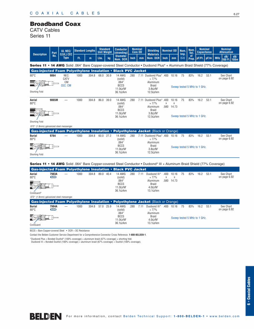
C O A X I A L C A B L E S 6.27
6 •
Coax
ial C
able
s
F o r m o r e i n f o r m a t i o n , c o n t a c t B e l d e n Te c h n i c a l S u p p o r t : 1 - 8 0 0 - B E L D E N - 1 • w w w . b e l d e n . c o m
Series 11 • 14 AWG Solid .064″ Bare Copper-covered Steel Conductor • Duobond Plus® + Aluminum Braid Shield (77% Coverage)
Gas-injected Foam Polyethylene Insulation • Black PVC Jacket80°C 9064 NEC: 1000 304.8 68.0 30.9 14 AWG .280 7.11 Duobond Plus* .400 10.16 75 83% 16.2 53.1
CATV (solid) + 77% CM .064″ Aluminum
CEC: CM BCCS Braid11.0Ω/M′ 3.8Ω/M′36.1Ω/km 12.5Ω/km
Aerial 9065M — 1000 304.8 86.0 39.0 14 AWG .280 7.11 Duobond Plus* .400 10.16 75 83% 16.2 53.180°C (solid) + 77% x x
.064″ Aluminum .580 14.73BCCS Braid
11.0Ω/M′ 3.8Ω/M′36.1Ω/km 12.5Ω/km
.072″ (1.8mm) galvanized steel messenger.
Gas-injected Foam Polyethylene Insulation • Polyethylene Jacket (Black or Orange)Burial 9764 — 1000 304.8 60.0 27.2 14 AWG .280 7.11 Duobond Plus* .400 10.16 75 83% 16.2 53.180°C (solid) + 77%
.064″ AluminumBCCS Braid
11.0Ω/M′ 3.8Ω/M′36.1Ω/km 12.5Ω/km
Series 11 • 14 AWG Solid .064″ Bare Copper-covered Steel Conductor • Duobond® III + Aluminum Braid Shield (77% Coverage)
Gas-injected Foam Polyethylene Insulation • Black PVC JacketAerial 7983A — 1000 304.8 89.0 40.4 14 AWG .280 7.11 Duobond III* .400 10.16 75 83% 16.2 53.180°C u (solid) + 77% x x
.064″ Aluminum .580 14.73BCCS Braid
11.0Ω/M′ 4.0Ω/M′36.1Ω/km 13.1Ω/km
.072″ (1.8mm) galvanized steel messenger.
Gas-injected Foam Polyethylene Insulation • Polyethylene Jacket (Black or Orange)Burial 7984A — 1000 304.8 57.0 25.9 14 AWG .280 7.11 Duobond III* .400 10.16 75 83% 16.2 53.180°C u (solid) + 77%
.064″ AluminumBCCS Braid
11.0Ω/M′ 4.0Ω/M′36.1Ω/km 13.1Ω/km
BCCS = Bare Copper-covered Steel • DCR = DC Resistance
Contact the Belden Customer Service Department for a Comprehensive Connector Cross Reference. 1-800-BELDEN-1.
*Duobond Plus = Bonded Duofoil® (100% coverage) + aluminum braid (67% coverage) + shorting fold. Duobond III = Bonded Duofoil (100% coverage) + aluminum braid (67% coverage) + Duofoil (100% coverage).
Broadband CoaxCATV CablesSeries 11
See Chart on page 6.92
See Chart on page 6.92
See Chart on page 6.92
Shorting Fold
CoreGuard®
Shorting Fold
Sweep tested 5 MHz to 1 GHz.
Sweep tested 5 MHz to 1 GHz.
Sweep tested 5 MHz to 1 GHz.
See Chart on page 6.92
Sweep tested 5 MHz to 1 GHz.
See Chart on page 6.92
Shorting Fold
ShieldingMaterialsNom. DCR
Nom.Imp.(Ω)
Nominal Core OD Nominal OD
Inch mm Inch mm
Conductor(stranding)DiameterNom. DCR
StandardUnit WeightStandard Lengths
Lbs. kgFt. m
UL NEC/C(UL) CEC
Type
PartNo.
MHz dB/100 Ft.
dB/100m
Nominal Attenuation
Nominal Capacitance
pF/mpF/Ft.
Nom.Vel.of
Prop.Description
CoreGuard
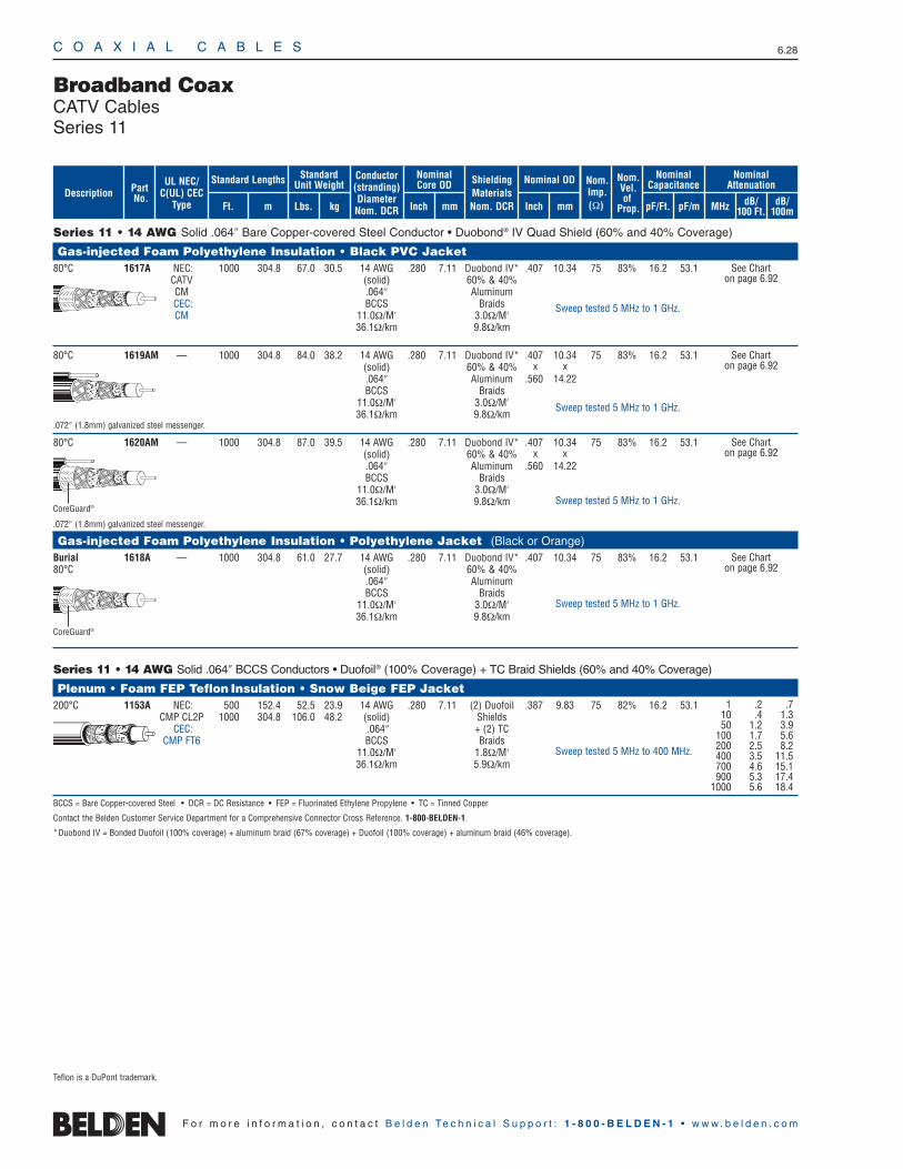
C O A X I A L C A B L E S 6.28
F o r m o r e i n f o r m a t i o n , c o n t a c t B e l d e n Te c h n i c a l S u p p o r t : 1 - 8 0 0 - B E L D E N - 1 • w w w . b e l d e n . c o m
Series 11 • 14 AWG Solid .064″ Bare Copper-covered Steel Conductor • Duobond® IV Quad Shield (60% and 40% Coverage)
Gas-injected Foam Polyethylene Insulation • Black PVC Jacket80°C 1617A NEC: 1000 304.8 67.0 30.5 14 AWG .280 7.11 Duobond IV* .407 10.34 75 83% 16.2 53.1
CATV (solid) 60% & 40%CM .064″ AluminumCEC: BCCS BraidsCM 11.0Ω/M′ 3.0Ω/M′
36.1Ω/km 9.8Ω/km
80°C 1619AM — 1000 304.8 84.0 38.2 14 AWG .280 7.11 Duobond IV* .407 10.34 75 83% 16.2 53.1(solid) 60% & 40% x x.064″ Aluminum .560 14.22BCCS Braids
11.0Ω/M′ 3.0Ω/M′36.1Ω/km 9.8Ω/km
.072″ (1.8mm) galvanized steel messenger.
80°C 1620AM — 1000 304.8 87.0 39.5 14 AWG .280 7.11 Duobond IV* .407 10.34 75 83% 16.2 53.1(solid) 60% & 40% x x.064″ Aluminum .560 14.22BCCS Braids
11.0Ω/M′ 3.0Ω/M′36.1Ω/km 9.8Ω/km
.072″ (1.8mm) galvanized steel messenger.
Gas-injected Foam Polyethylene Insulation • Polyethylene Jacket (Black or Orange)Burial 1618A — 1000 304.8 61.0 27.7 14 AWG .280 7.11 Duobond IV* .407 10.34 75 83% 16.2 53.180°C (solid) 60% & 40%
.064″ AluminumBCCS Braids
11.0Ω/M′ 3.0Ω/M′36.1Ω/km 9.8Ω/km
Series 11 • 14 AWG Solid .064″ BCCS Conductors • Duofoil® (100% Coverage) + TC Braid Shields (60% and 40% Coverage)
Plenum • Foam FEP Teflon Insulation • Snow Beige FEP Jacket200°C 1153A NEC: 500 152.4 52.5 23.9 14 AWG .280 7.11 (2) Duofoil .387 9.83 75 82% 16.2 53.1
CMP CL2P 1000 304.8 106.0 48.2 (solid) ShieldsCEC: .064″ + (2) TC
CMP FT6 BCCS Braids11.0Ω/M′ 1.8Ω/M′36.1Ω/km 5.9Ω/km
BCCS = Bare Copper-covered Steel • DCR = DC Resistance • FEP = Fluorinated Ethylene Propylene • TC = Tinned Copper
Contact the Belden Customer Service Department for a Comprehensive Connector Cross Reference. 1-800-BELDEN-1.
*Duobond IV = Bonded Duofoil (100% coverage) + aluminum braid (67% coverage) + Duofoil (100% coverage) + aluminum braid (46% coverage).
Broadband CoaxCATV CablesSeries 11
1 .2 .710 .4 1.350 1.2 3.9
100 1.7 5.6200 2.5 8.2400 3.5 11.5700 4.6 15.1900 5.3 17.4
1000 5.6 18.4
See Chart on page 6.92
See Chart on page 6.92
See Chart on page 6.92
See Chart on page 6.92
CoreGuard®
CoreGuard®
Sweep tested 5 MHz to 1 GHz.
Sweep tested 5 MHz to 1 GHz.
Sweep tested 5 MHz to 1 GHz.
Sweep tested 5 MHz to 1 GHz.
Sweep tested 5 MHz to 400 MHz.
ShieldingMaterialsNom. DCR
Nom.Imp.(Ω)
Nominal Core OD Nominal OD
Inch mm Inch mm
Conductor(stranding)DiameterNom. DCR
StandardUnit WeightStandard Lengths
Lbs. kgFt. m
UL NEC/C(UL) CEC
Type
PartNo.
MHz dB/100 Ft.
dB/100m
Nominal Attenuation
Nominal Capacitance
pF/mpF/Ft.
Nom.Vel.of
Prop.Description
Teflon is a DuPont trademark.
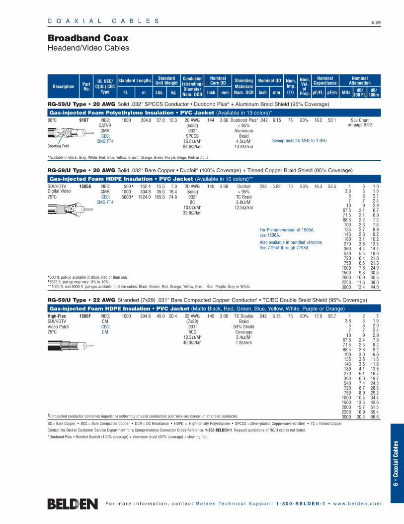
C O A X I A L C A B L E S 6.29
6 •
Coax
ial C
able
s
F o r m o r e i n f o r m a t i o n , c o n t a c t B e l d e n Te c h n i c a l S u p p o r t : 1 - 8 0 0 - B E L D E N - 1 • w w w . b e l d e n . c o m
RG-59/U Type • 20 AWG Solid .032″ SPCCS Conductor • Duobond Plus® + Aluminum Braid Shield (95% Coverage)
Gas-injected Foam Polyethylene Insulation • PVC Jacket (Available in 13 colors)*80°C 9167 NEC: 1000 304.8 27.0 12.3 20 AWG .144 3.66 Duobond Plus* .242 6.15 75 83% 16.2 53.1
CATVR (solid) + 95%CMR .032″ AluminumCEC: SPCCS Braid
CMG FT4 25.8Ω/M′ 4.5Ω/M′84.6Ω/km 14.8Ω/km
*Available in Black, Gray, White, Red, Blue, Yellow, Brown, Orange, Green, Purple, Beige, Pink or Aqua.
RG-59/U Type • 20 AWG Solid .032″ Bare Copper • Duofoil® (100% Coverage) + Tinned Copper Braid Shield (95% Coverage)
Gas-injected Foam HDPE Insulation • PVC Jacket (Available in 10 colors)**SDI/HDTV 1505A NEC: 500 152.4 15.5 7.0 20 AWG .145 3.68 Duofoil .233 5.92 75 83% 16.3 53.5Digital Video CMR 1000 304.8 35.0 16.4 (solid) + 95%75°C CEC: 5000 1524.0 165.0 74.8 .032″ TC Braid
CMG FT4 BC 3.8Ω/M′10.0Ω/M′ 12.5Ω/km32.8Ω/km
500 ft. put-up available in Black, Red or Blue only.5000 ft. put-up may vary -0% to 10%.**1000 ft. and 5000 ft. put-ups available in all ten colors: Black, Brown, Red, Orange, Yellow, Green, Blue, Purple, Gray or White.
RG-59/U Type • 22 AWG Stranded (7x29) .031″ Bare Compacted Copper Conductor† • TC/BC Double Braid Shield (95% Coverage)
Gas-injected Foam HDPE Insulation • PVC Jacket (Matte Black, Red, Green, Blue, Yellow, White, Purple or Orange)High-Flex 1505F NEC: 1000 304.8 45.0 20.4 22 AWG .145 3.68 TC Double .242 6.15 75 80% 17.0 55.7SDI/HDTV CM (7x29) BraidVideo Patch CEC: .031″ 94% Shield75°C CM BCC Coverage
12.2Ω/M′ 2.4Ω/M′40.0Ω/km 7.8Ω/km
†Compacted conductor combines impedance uniformity of solid conductors and “nick-resistance” of stranded conductor.
BC = Bare Copper • BCC = Bare Compacted Copper • DCR = DC Resistance • HDPE = High-density Polyethylene • SPCCS = Silver-plated, Copper-covered Steel • TC = Tinned Copper
Contact the Belden Customer Service Department for a Comprehensive Connector Cross Reference. 1-800-BELDEN-1. Request quotations of RG/U cables not listed.
*Duobond Plus = Bonded Duofoil (100% coverage) + aluminum braid (67% coverage) + shorting fold.
Broadband CoaxHeadend/Video Cables
See Chart on page 6.92
Sweep tested 5 MHz to 1 GHz.Shorting Fold
ShieldingMaterialsNom. DCR
Nom.Imp.(Ω)
Nominal Core OD Nominal OD
Inch mm Inch mm
Conductor(stranding)DiameterNom. DCR
StandardUnit WeightStandard Lengths
Lbs. kgFt. m
UL NEC/C(UL) CEC
Type
PartNo.
MHz dB/100 Ft.
dB/100m
Nominal Attenuation
Nominal Capacitance
pF/mpF/Ft.
Nom.Vel.of
Prop.Description
For Plenum version of 1505A, see 1506A.
Also available in bundled versions. See 7794A through 7798A.
1 .2 .73.6 .5 1.6
5 .6 2.07 .7 2.4
10 .9 2.967.5 2.4 7.971.5 2.5 8.288.5 2.8 9.2100 3.0 9.8135 3.5 11.5143 3.6 11.8180 4.1 13.5270 5.1 16.7360 6.0 19.7540 7.4 24.3720 8.7 28.5750 8.9 29.2
1000 10.5 34.41500 13.3 43.62000 15.7 51.52250 16.9 55.43000 20.3 66.6
1 .3 1.03.6 .6 1.8
5 .6 2.17 .7 2.4
10 .9 2.967.5 2.1 6.771.5 2.1 6.988.5 2.2 7.2100 2.3 7.6135 2.7 8.9143 2.8 9.2180 3.1 10.2270 3.8 12.5360 4.4 14.4540 5.5 18.0720 6.4 21.0750 6.5 21.3
1000 7.6 24.91500 9.3 30.52000 10.9 30.52250 11.6 38.03000 13.4 44.0
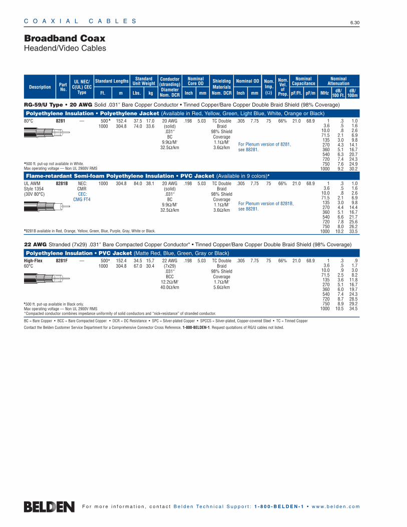
C O A X I A L C A B L E S 6.30
F o r m o r e i n f o r m a t i o n , c o n t a c t B e l d e n Te c h n i c a l S u p p o r t : 1 - 8 0 0 - B E L D E N - 1 • w w w . b e l d e n . c o m
RG-59/U Type • 20 AWG Solid .031″ Bare Copper Conductor • Tinned Copper/Bare Copper Double Braid Shield (98% Coverage)
Polyethylene Insulation • Polyethylene Jacket (Available in Red, Yellow, Green, Light Blue, White, Orange or Black)80°C 8281 — 500 152.4 37.5 17.0 20 AWG .198 5.03 TC Double .305 7.75 75 66% 21.0 68.9
1000 304.8 74.0 33.6 (solid) Braid.031″ 98% Shield
BC Coverage9.9Ω/M′ 1.1Ω/M′
32.5Ω/km 3.6Ω/km
500 ft. put-up not available in White.Max operating voltage — Non UL 2900V RMS
Flame-retardant Semi-foam Polyethylene Insulation • PVC Jacket (Available in 9 colors)
UL AWM 8281B NEC: 1000 304.8 84.0 38.1 20 AWG .198 5.03 TC Double .305 7.75 75 66% 21.0 68.9Style 1354 CMR (solid) Braid(30V 80°C) CEC: .031″ 98% Shield
CMG FT4 BC Coverage9.9Ω/M′ 1.1Ω/M′
32.5Ω/km 3.6Ω/km
8281B available in Red, Orange, Yellow, Green, Blue, Purple, Gray, White or Black.
22 AWG Stranded (7x29) .031″ Bare Compacted Copper Conductor* • Tinned Copper/Bare Copper Double Braid Shield (98% Coverage)
Polyethylene Insulation • PVC Jacket (Matte Red, Blue, Green, Gray or Black)High-Flex 8281F — 500 152.4 34.5 15.7 22 AWG .198 5.03 TC Double .305 7.75 75 66% 21.0 68.960°C 1000 304.8 67.0 30.4 (7x29) Braid
.031″ 98% ShieldBCC Coverage
12.2Ω/M′ 1.7Ω/M′40.0Ω/km 5.6Ω/km
500 ft. put-up available in Black only.Max operating voltage — Non UL 2900V RMS*Compacted conductor combines impedance uniformity of solid conductors and “nick-resistance” of stranded conductor.
BC = Bare Copper • BCC = Bare Compacted Copper • DCR = DC Resistance • SPC = Silver-plated Copper • SPCCS = Silver-plated, Copper-covered Steel • TC = Tinned Copper
Contact the Belden Customer Service Department for a Comprehensive Connector Cross Reference. 1-800-BELDEN-1. Request quotations of RG/U cables not listed.
Broadband CoaxHeadend/Video Cables
ShieldingMaterialsNom. DCR
Nom.Imp.(Ω)
Nominal Core OD Nominal OD
Inch mm Inch mm
Conductor(stranding)DiameterNom. DCR
StandardUnit WeightStandard Lengths
Lbs. kgFt. m
UL NEC/C(UL) CEC
Type
PartNo.
MHz dB/100 Ft.
dB/100m
Nominal Attenuation
Nominal Capacitance
pF/mpF/Ft.
Nom.Vel.of
Prop.Description
1 .3 1.03.6 .5 1.6
10.0 .8 2.671.5 2.1 6.9135 3.0 9.8270 4.3 14.1360 5.1 16.7540 6.3 20.7720 7.4 24.3750 7.6 24.9
1000 9.2 30.2
1 .3 1.03.6 .5 1.6
10.0 .8 2.671.5 2.1 6.9135 3.0 9.8270 4.4 14.4360 5.1 16.7540 6.6 21.7720 7.8 25.6750 8.0 26.2
1000 10.2 33.5
For Plenum version of 8281B, see 88281.
For Plenum version of 8281, see 88281.
1 .3 .93.6 .5 1.7
10.0 .9 3.071.5 2.5 8.2135 3.6 11.8270 5.1 16.7360 6.0 19.7540 7.4 24.3720 8.7 28.5750 8.9 29.2
1000 10.5 34.5
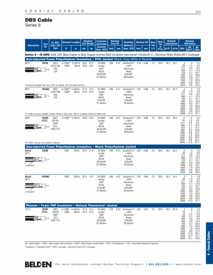
C O A X I A L C A B L E S 6.31
6 •
Coax
ial C
able
s
F o r m o r e i n f o r m a t i o n , c o n t a c t B e l d e n Te c h n i c a l S u p p o r t : 1 - 8 0 0 - B E L D E N - 1 • w w w . b e l d e n . c o m
Series 6 • 18 AWG Solid .040″ Bare Copper or Bare Copper-covered Steel Conductor (see below) • Duobond® II + Aluminum Braid Shield (60% Coverage)
Gas-injected Foam Polyethylene Insulation • PVC Jacket (Black, Gray, White or Neutral)80°C 1829A NEC: U-1000 † U-304.8 29.0 13.2 18 AWG .180 4.57 Duobond II* .270 6.86 75 83% 16.2 53.1
CATV CM 1000 † 304.8 29.0 13.2 (solid) + 60% CEC: .040″ AluminumCM BCCS Braid
28.0Ω/M′ 9.0Ω/M′91.9Ω/km 29.5Ω/km
†Final put-up length may vary ±10% for spools, ±5% for unreel cartons.
80°C 1829AC NEC: U-1000 U-304.8 27.0 12.3 18 AWG .180 4.57 Duobond II* .270 6.86 75 83% 16.2 53.1CATV CM 1000 304.8 27.0 12.3 (solid) + 60%
CEC: .040″ AluminumCM BCAC Braid
6.4Ω/M′ 9.0Ω/M′21.0Ω/km 29.5Ω/km
U-1000 ft. put-up available in Black, White or Gray only. 1000 ft. available in White or Black only.
80°C 1829R NEC: U-1000 U-304.8 29.0 13.2 18 AWG .180 4.57 Duobond II* .270 6.86 75 83% 16.2 53.1u CATVR, (solid) + 60%
CMR .040″ AluminumCEC: BCCS Braid
CMG FT4 28.0Ω/M′ 9.0Ω/M′21.0Ω/km 29.5Ω/km
U-1000 ft. put-up not available in Neutral.
Gas-injected Foam Polyethylene Insulation • Black Polyethylene JacketBurial 1829B — 1000 304.8 26.0 11.8 18 AWG .180 4.57 Duobond II* .270 6.86 75 83% 16.2 53.180°C (solid) + 60%
.040″ AluminumBCCS Braid
28.0Ω/M′ 9.0Ω/M′91.9Ω/km 29.5Ω/km
Burial 1829BC — 1000 304.8 27.0 12.3 18 AWG .180 4.57 Duobond II* .270 6.86 75 83% 16.2 53.180°C (solid) + 60%
.040″ AluminumBCAC Braid
6.4Ω/M′ 9.0Ω/M′21.0Ω/km 29.5Ω/km
Plenum • Foam FEP Insulation • Natural Flamarrest® Jacket75°C 1829P NEC: U-1000 U-304.8 27.0 12.3 18 AWG .170 4.32 Duobond II* .235 5.97 75 83% 16.3 53.4
u CATVP, 1000 304.8 27.0 12.3 (solid) + 60%CMP .040″ AluminumCEC: BCCS Braid
CMP FT6 28.0Ω/M′ 9.0Ω/M′91.9Ω/km 29.5Ω/km
BC = Bare Copper • BCAC = Bare Copper Anti-corrosion • BCCS = Bare Copper-covered Steel • DCR = DC Resistance • FEP = Fluorinated Ethylene Propylene
*Duobond II = Bonded Duofoil® (100% coverage) + aluminum braid (67% coverage).
DBS CableSeries 6
5 .5 1.655 1.4 4.6
211 2.6 8.5500 4.1 13.5750 5.1 16.7862 5.5 18.0
1000 6.0 19.71450 7.8 25.61800 8.6 28.22250 9.8 32.2
5 .5 1.655 1.4 4.6
211 2.6 8.5500 4.1 13.5750 5.1 16.7862 5.5 18.0
1000 6.0 19.71450 7.8 25.61800 8.6 28.22250 9.8 32.23000 11.3 37.1
5 .5 1.655 1.4 4.6
211 2.6 8.5500 4.1 13.5750 5.1 16.7862 5.5 18.0
1000 6.0 19.71450 7.8 25.61800 8.6 28.22250 9.8 32.2
CoreGuard®
CoreGuard®
ShieldingMaterialsNom. DCR
Nom.Imp.(Ω)
Nominal Core OD Nominal OD
Inch mm Inch mm
Conductor(stranding)DiameterNom. DCR
StandardUnit WeightStandard Lengths
Lbs. kgFt. m
UL NEC/C(UL) CEC
Type
PartNo.
MHz dB/100 Ft.
dB/100m
Nominal Attenuation
Nominal Capacitance
pF/mpF/Ft.
Nom.Vel.of
Prop.Description
5 .5 1.655 1.4 4.6
211 2.6 8.5500 4.1 13.5750 5.1 16.7862 5.5 18.0
1000 6.0 19.71450 7.8 25.61800 8.6 28.22250 9.8 32.23000 11.3 37.1
1 .3 1.010 .7 2.250 1.5 4.9
100 2.1 6.9200 3.0 9.8400 4.4 14.4700 6.1 20.0900 7.2 23.6
1000 7.6 24.91450 9.6 31.51800 11.0 36.12250 12.7 41.73000 15.1 49.5
5 .5 1.655 1.4 4.6
211 2.6 8.5500 4.1 13.5750 5.1 16.7862 5.5 18.0
1000 6.0 19.71450 7.8 25.61800 8.6 28.22250 9.8 32.23000 11.3 37.1
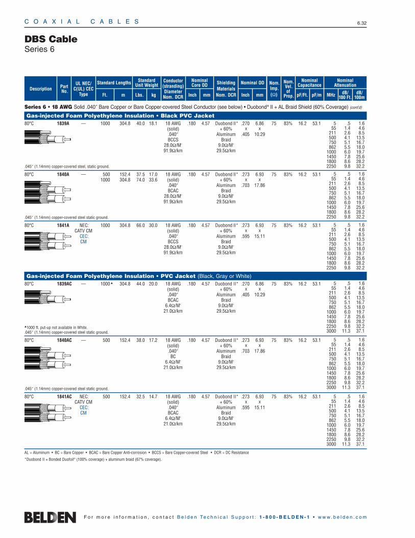
C O A X I A L C A B L E S 6.32
F o r m o r e i n f o r m a t i o n , c o n t a c t B e l d e n Te c h n i c a l S u p p o r t : 1 - 8 0 0 - B E L D E N - 1 • w w w . b e l d e n . c o m
Series 6 • 18 AWG Solid .040″ Bare Copper or Bare Copper-covered Steel Conductor (see below) • Duobond® II + AL Braid Shield (60% Coverage) (cont’d)
Gas-injected Foam Polyethylene Insulation • Black PVC Jacket80°C 1839A — 1000 304.8 40.0 18.1 18 AWG .180 4.57 Duobond II* .270 6.86 75 83% 16.2 53.1
(solid) + 60% x x.040″ Aluminum .405 10.29BCCS Braid
28.0Ω/M′ 9.0Ω/M′91.9Ω/km 29.5Ω/km
.045″ (1.14mm) copper-covered steel, static ground.
80°C 1840A — 500 152.4 37.5 17.0 18 AWG .180 4.57 Duobond II* .273 6.93 75 83% 16.2 53.11000 304.8 74.0 33.6 (solid) + 60% x x
.040″ Aluminum .703 17.86BCAC Braid
28.0Ω/M′ 9.0Ω/M′91.9Ω/km 29.5Ω/km
.045″ (1.14mm) copper-covered steel static ground.
80°C 1841A NEC: 1000 304.8 66.0 30.0 18 AWG .180 4.57 Duobond II* .273 6.93 75 83% 16.2 53.1CATV CM (solid) + 60% x x
CEC: .040″ Aluminum .595 15.11CM BCCS Braid
28.0Ω/M′ 9.0Ω/M′91.9Ω/km 29.5Ω/km
Gas-injected Foam Polyethylene Insulation • PVC Jacket (Black, Gray or White)80°C 1839AC — 1000 304.8 44.0 20.0 18 AWG .180 4.57 Duobond II* .270 6.86 75 83% 16.2 53.1
(solid) + 60% x x.040″ Aluminum .405 10.29BCAC Braid
6.4Ω/M′ 9.0Ω/M′21.0Ω/km 29.5Ω/km
1000 ft. put-up not available in White..045″ (1.14mm) copper-covered steel static ground.
80°C 1840AC — 500 152.4 38.0 17.2 18 AWG .180 4.57 Duobond II* .273 6.93 75 83% 16.2 53.1(solid) + 60% x x.040″ Aluminum .703 17.86
BC Braid6.4Ω/M′ 9.0Ω/M′
21.0Ω/km 29.5Ω/km
.045″ (1.14mm) copper-covered steel static ground.
80°C 1841AC NEC: 500 152.4 32.5 14.7 18 AWG .180 4.57 Duobond II* .273 6.93 75 83% 16.2 53.1CATV CM (solid) + 60% x x
CEC: .040″ Aluminum .595 15.11CM BCAC Braid
6.4Ω/M′ 9.0Ω/M′21.0Ω/km 29.5Ω/km
AL = Aluminum • BC = Bare Copper • BCAC = Bare Copper Anti-corrosion • BCCS = Bare Copper-covered Steel • DCR = DC Resistance
*Duobond II = Bonded Duofoil® (100% coverage) + aluminum braid (67% coverage).
DBS CableSeries 6
5 .5 1.655 1.4 4.6
211 2.6 8.5500 4.1 13.5750 5.1 16.7862 5.5 18.0
1000 6.0 19.71450 7.8 25.61800 8.6 28.22250 9.8 32.2
5 .5 1.655 1.4 4.6
211 2.6 8.5500 4.1 13.5750 5.1 16.7862 5.5 18.0
1000 6.0 19.71450 7.8 25.61800 8.6 28.22250 9.8 32.2
5 .5 1.655 1.4 4.6
211 2.6 8.5500 4.1 13.5750 5.1 16.7862 5.5 18.0
1000 6.0 19.71450 7.8 25.61800 8.6 28.22250 9.8 32.2
5 .5 1.655 1.4 4.6
211 2.6 8.5500 4.1 13.5750 5.1 16.7862 5.5 18.0
1000 6.0 19.71450 7.8 25.61800 8.6 28.22250 9.8 32.23000 11.3 37.1
5 .5 1.655 1.4 4.6
211 2.6 8.5500 4.1 13.5750 5.1 16.7862 5.5 18.0
1000 6.0 19.71450 7.8 25.61800 8.6 28.22250 9.8 32.23000 11.3 37.1
5 .5 1.655 1.4 4.6
211 2.6 8.5500 4.1 13.5750 5.1 16.7862 5.5 18.0
1000 6.0 19.71450 7.8 25.61800 8.6 28.22250 9.8 32.23000 11.3 37.1
ShieldingMaterialsNom. DCR
Nom.Imp.(Ω)
Nominal Core OD Nominal OD
Inch mm Inch mm
Conductor(stranding)DiameterNom. DCR
StandardUnit WeightStandard Lengths
Lbs. kgFt. m
UL NEC/C(UL) CEC
Type
PartNo.
MHz dB/100 Ft.
dB/100m
Nominal Attenuation
Nominal Capacitance
pF/mpF/Ft.
Nom.Vel.of
Prop.Description
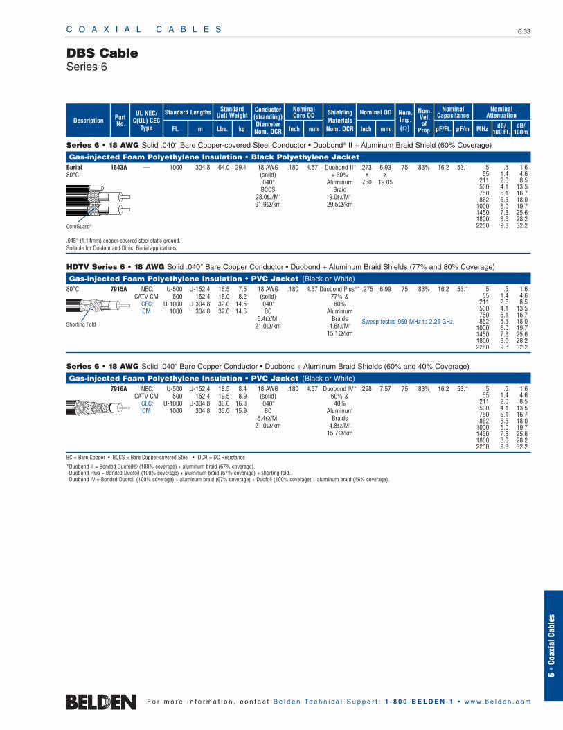
Series 6 • 18 AWG Solid .040″ Bare Copper-covered Steel Conductor • Duobond® II + Aluminum Braid Shield (60% Coverage)
Gas-injected Foam Polyethylene Insulation • Black Polyethylene JacketBurial 1843A — 1000 304.8 64.0 29.1 18 AWG .180 4.57 Duobond II* .273 6.93 75 83% 16.2 53.180°C (solid) + 60% x x
.040″ Aluminum .750 19.05BCCS Braid
28.0Ω/M′ 9.0Ω/M′91.9Ω/km 29.5Ω/km
.045″ (1.14mm) copper-covered steel static ground.Suitable for Outdoor and Direct Burial applications.
HDTV Series 6 • 18 AWG Solid .040″ Bare Copper Conductor • Duobond + Aluminum Braid Shields (77% and 80% Coverage)
Gas-injected Foam Polyethylene Insulation • PVC Jacket (Black or White)80°C 7915A NEC: U-500 U-152.4 16.5 7.5 18 AWG .180 4.57 Duobond Plus®* .275 6.99 75 83% 16.2 53.1
CATV CM 500 152.4 18.0 8.2 (solid) 77% & CEC: U-1000 U-304.8 32.0 14.5 .040″ 80%CM 1000 304.8 32.0 14.5 BC Aluminum
6.4Ω/M′ Braids21.0Ω/km 4.6Ω/M′
15.1Ω/km
Series 6 • 18 AWG Solid .040″ Bare Copper Conductor • Duobond + Aluminum Braid Shields (60% and 40% Coverage)
Gas-injected Foam Polyethylene Insulation • PVC Jacket (Black or White)7916A NEC: U-500 U-152.4 18.5 8.4 18 AWG .180 4.57 Duobond IV* .298 7.57 75 83% 16.2 53.1
CATV CM 500 152.4 19.5 8.9 (solid) 60% & CEC: U-1000 U-304.8 36.0 16.3 .040″ 40%CM 1000 304.8 35.0 15.9 BC Aluminum
6.4Ω/M′ Braids21.0Ω/km 4.8Ω/M′
15.7Ω/km
BC = Bare Copper • BCCS = Bare Copper-covered Steel • DCR = DC Resistance
*Duobond II = Bonded Duofoil® (100% coverage) + aluminum braid (67% coverage).Duobond Plus = Bonded Duofoil (100% coverage) + aluminum braid (67% coverage) + shorting fold.Duobond IV = Bonded Duofoil (100% coverage) + aluminum braid (67% coverage) + Duofoil (100% coverage) + aluminum braid (46% coverage).
C O A X I A L C A B L E S 6.33
6 •
Coax
ial C
able
s
F o r m o r e i n f o r m a t i o n , c o n t a c t B e l d e n Te c h n i c a l S u p p o r t : 1 - 8 0 0 - B E L D E N - 1 • w w w . b e l d e n . c o m
5 .5 1.655 1.4 4.6
211 2.6 8.5500 4.1 13.5750 5.1 16.7862 5.5 18.0
1000 6.0 19.71450 7.8 25.61800 8.6 28.22250 9.8 32.2
Sweep tested 950 MHz to 2.25 GHz.Shorting Fold
DBS CableSeries 6
5 .5 1.655 1.4 4.6
211 2.6 8.5500 4.1 13.5750 5.1 16.7862 5.5 18.0
1000 6.0 19.71450 7.8 25.61800 8.6 28.22250 9.8 32.2CoreGuard®
ShieldingMaterialsNom. DCR
Nom.Imp.(Ω)
Nominal Core OD Nominal OD
Inch mm Inch mm
Conductor(stranding)DiameterNom. DCR
StandardUnit WeightStandard Lengths
Lbs. kgFt. m
UL NEC/C(UL) CEC
Type
PartNo.
MHz dB/100 Ft.
dB/100m
Nominal Attenuation
Nominal Capacitance
pF/mpF/Ft.
Nom.Vel.of
Prop.Description
5 .5 1.655 1.4 4.6
211 2.6 8.5500 4.1 13.5750 5.1 16.7862 5.5 18.0
1000 6.0 19.71450 7.8 25.61800 8.6 28.22250 9.8 32.2
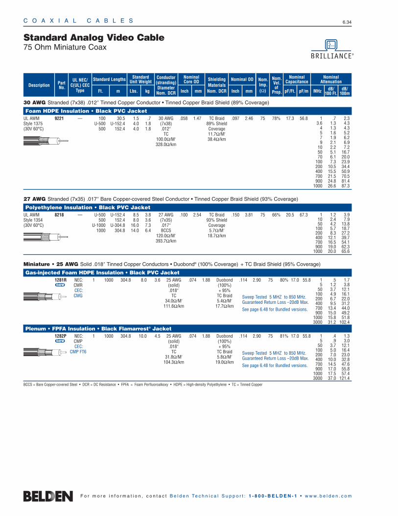
C O A X I A L C A B L E S 6.34
F o r m o r e i n f o r m a t i o n , c o n t a c t B e l d e n Te c h n i c a l S u p p o r t : 1 - 8 0 0 - B E L D E N - 1 • w w w . b e l d e n . c o m
30 AWG Stranded (7x38) .012″ Tinned Copper Conductor • Tinned Copper Braid Shield (89% Coverage)
Foam HDPE Insulation • Black PVC JacketUL AWM 9221 — 100 30.5 1.5 .7 30 AWG .058 1.47 TC Braid .097 2.46 75 78% 17.3 56.8Style 1375 U-500 U-152.4 4.0 1.8 (7x38) 89% Shield(30V 60°C) 500 152.4 4.0 1.8 .012″ Coverage
TC 11.7Ω/M′100.0Ω/M′ 38.4Ω/km328.0Ω/km
27 AWG Stranded (7x35) .017″ Bare Copper-covered Steel Conductor • Tinned Copper Braid Shield (93% Coverage)
Polyethylene Insulation • Black PVC JacketUL AWM 8218 — U-500 U-152.4 8.5 3.8 27 AWG .100 2.54 TC Braid .150 3.81 75 66% 20.5 67.3Style 1354 500 152.4 8.0 3.6 (7x35) 93% Shield(30V 60°C) U-1000 U-304.8 16.0 7.3 .017″ Coverage
1000 304.8 14.0 6.4 BCCS 5.7Ω/M′120.0Ω/M′ 18.7Ω/km393.7Ω/km
Miniature • 25 AWG Solid .018″ Tinned Copper Conductors • Duobond® (100% Coverage) + TC Braid Shield (95% Coverage)
Gas-injected Foam HDPE Insulation • Black PVC Jacket1281R NEC: 1 1000 304.8 8.0 3.6 25 AWG .074 1.88 Duobond .114 2.90 75 80% 17.0 55.8u CMR (solid) (100%)
CEC: .018″ + 95% CMG TC TC Braid
34.0Ω/M′ 5.4Ω/M′111.6Ω/km 17.7Ω/km
Plenum • FPFA Insulation • Black Flamarrest® Jacket1282P NEC: 1 1000 304.8 10.0 4.5 25 AWG .074 1.88 Duobond .114 2.90 75 81% 17.0 55.8u CMP (solid) (100%)
CEC: .018″ + 95%CMP FT6 TC TC Braid
31.8Ω/M′ 5.8Ω/M′104.3Ω/km 19.0Ω/km
BCCS = Bare Copper-covered Steel • DCR = DC Resistance • FPFA = Foam Perfluoroalkoxy • HDPE = High-density Polyethylene • TC = Tinned Copper
Standard Analog Video Cable75 Ohm Miniature Coax
1 .7 2.33.6 1.3 4.3
4 1.3 4.35 1.6 5.27 1.9 6.29 2.1 6.9
10 2.2 7.250 5.1 16.770 6.1 20.0
100 7.3 23.9200 10.5 34.4400 15.5 50.9700 21.5 70.5900 24.8 81.4
1000 26.6 87.3
1 1.2 3.910 2.4 7.950 4.2 13.8
100 5.7 18.7200 8.3 27.2400 12.1 39.7700 16.5 54.1900 19.0 62.3
1000 20.0 65.6
ShieldingMaterialsNom. DCR
Nom.Imp.(Ω)
Nominal Core OD Nominal OD
Inch mm Inch mm
Conductor(stranding)DiameterNom. DCR
StandardUnit WeightStandard Lengths
Lbs. kgFt. m
UL NEC/C(UL) CEC
Type
PartNo.
MHz dB/100 Ft.
dB/100m
Nominal Attenuation
Nominal Capacitance
pF/mpF/Ft.
Nom.Vel.of
Prop.Description
Sweep Tested 5 MHZ to 850 MHz.Guaranteed Return Loss –20dB Max.
See page 6.48 for Bundled versions.
1 .4 1.3 5 .9 3.0
50 3.7 12.1 100 5.0 16.4 200 7.0 23.0 400 10.0 32.8 700 14.5 47.6 900 17.0 55.8
1000 17.5 57.4 3000 37.0 121.4
Sweep Tested 5 MHZ to 850 MHz.Guaranteed Return Loss –20dB Max.
See page 6.48 for Bundled versions.
1 .5 1.7 5 1.2 3.8
50 3.7 12.1 100 4.9 16.1 200 6.7 22.0 400 9.5 31.2 700 13.4 44.0 900 15.0 49.2
1000 15.8 51.8 3000 31.2 102.4
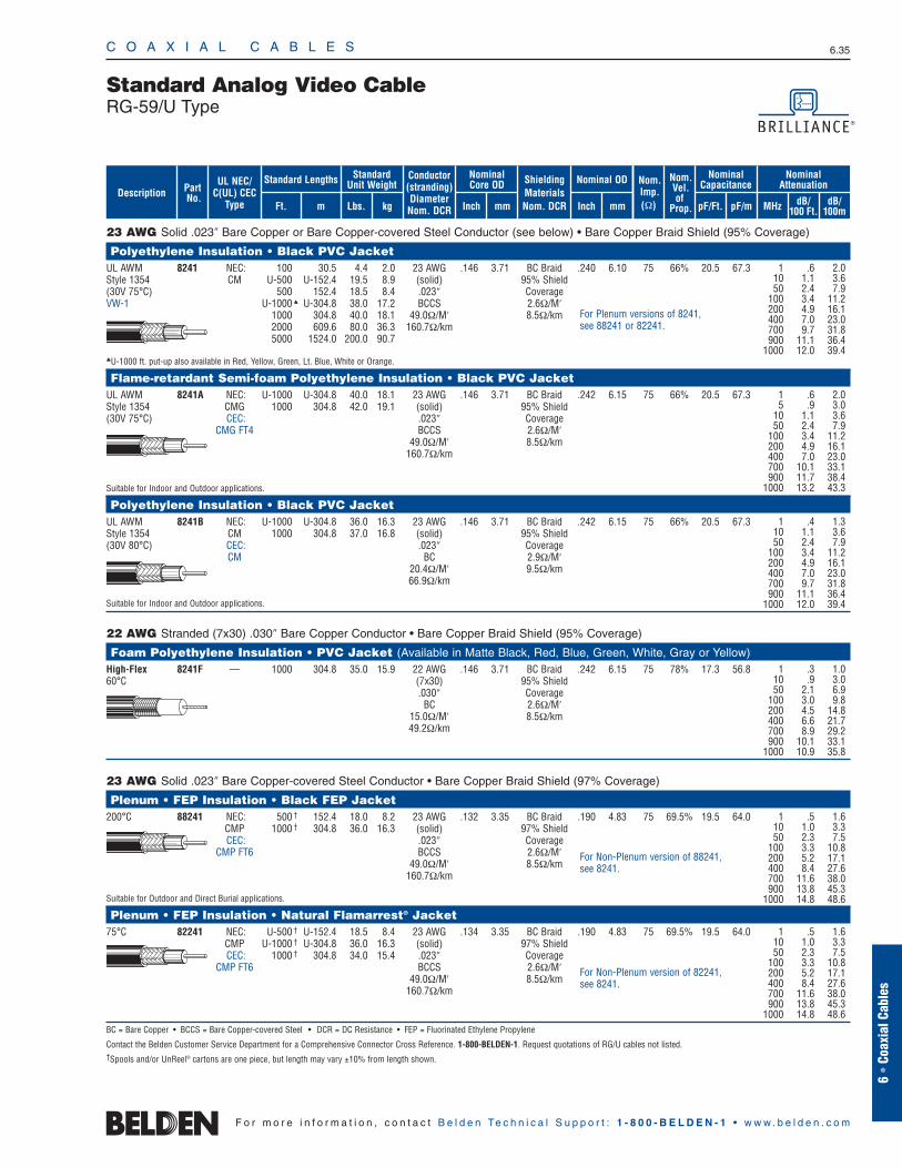
23 AWG Solid .023″ Bare Copper or Bare Copper-covered Steel Conductor (see below) • Bare Copper Braid Shield (95% Coverage)
Polyethylene Insulation • Black PVC JacketUL AWM 8241 NEC: 100 30.5 4.4 2.0 23 AWG .146 3.71 BC Braid .240 6.10 75 66% 20.5 67.3Style 1354 CM U-500 U-152.4 19.5 8.9 (solid) 95% Shield(30V 75°C) 500 152.4 18.5 8.4 .023″ CoverageVW-1 U-1000 U-304.8 38.0 17.2 BCCS 2.6Ω/M′
1000 304.8 40.0 18.1 49.0Ω/M′ 8.5Ω/km2000 609.6 80.0 36.3 160.7Ω/km5000 1524.0 200.0 90.7
U-1000 ft. put-up also available in Red, Yellow, Green, Lt. Blue, White or Orange.
Flame-retardant Semi-foam Polyethylene Insulation • Black PVC JacketUL AWM 8241A NEC: U-1000 U-304.8 40.0 18.1 23 AWG .146 3.71 BC Braid .242 6.15 75 66% 20.5 67.3Style 1354 CMG 1000 304.8 42.0 19.1 (solid) 95% Shield(30V 75°C) CEC: .023″ Coverage
CMG FT4 BCCS 2.6Ω/M′49.0Ω/M′ 8.5Ω/km
160.7Ω/km
Suitable for Indoor and Outdoor applications.
Polyethylene Insulation • Black PVC JacketUL AWM 8241B NEC: U-1000 U-304.8 36.0 16.3 23 AWG .146 3.71 BC Braid .242 6.15 75 66% 20.5 67.3Style 1354 CM 1000 304.8 37.0 16.8 (solid) 95% Shield(30V 80°C) CEC: .023″ Coverage
CM BC 2.9Ω/M′20.4Ω/M′ 9.5Ω/km66.9Ω/km
Suitable for Indoor and Outdoor applications.
22 AWG Stranded (7x30) .030″ Bare Copper Conductor • Bare Copper Braid Shield (95% Coverage)
Foam Polyethylene Insulation • PVC Jacket (Available in Matte Black, Red, Blue, Green, White, Gray or Yellow)High-Flex 8241F — 1000 304.8 35.0 15.9 22 AWG .146 3.71 BC Braid .242 6.15 75 78% 17.3 56.860°C (7x30) 95% Shield
.030″ CoverageBC 2.6Ω/M′
15.0Ω/M′ 8.5Ω/km49.2Ω/km
23 AWG Solid .023″ Bare Copper-covered Steel Conductor • Bare Copper Braid Shield (97% Coverage)
Plenum • FEP Insulation • Black FEP Jacket200°C 88241 NEC: 500 † 152.4 18.0 8.2 23 AWG .132 3.35 BC Braid .190 4.83 75 69.5% 19.5 64.0
CMP 1000 † 304.8 36.0 16.3 (solid) 97% ShieldCEC: .023″ Coverage
CMP FT6 BCCS 2.6Ω/M′49.0Ω/M′ 8.5Ω/km
160.7Ω/km
Suitable for Outdoor and Direct Burial applications.
Plenum • FEP Insulation • Natural Flamarrest® Jacket75°C 82241 NEC: U-500 † U-152.4 18.5 8.4 23 AWG .134 3.35 BC Braid .190 4.83 75 69.5% 19.5 64.0
CMP U-1000 † U-304.8 36.0 16.3 (solid) 97% ShieldCEC: 1000 † 304.8 34.0 15.4 .023″ Coverage
CMP FT6 BCCS 2.6Ω/M′49.0Ω/M′ 8.5Ω/km
160.7Ω/km
BC = Bare Copper • BCCS = Bare Copper-covered Steel • DCR = DC Resistance • FEP = Fluorinated Ethylene Propylene
Contact the Belden Customer Service Department for a Comprehensive Connector Cross Reference. 1-800-BELDEN-1. Request quotations of RG/U cables not listed.†Spools and/or UnReel® cartons are one piece, but length may vary ±10% from length shown.
C O A X I A L C A B L E S 6.35
1 .6 2.010 1.1 3.650 2.4 7.9
100 3.4 11.2200 4.9 16.1400 7.0 23.0700 9.7 31.8900 11.1 36.4
1000 12.0 39.4
1 .6 2.05 .9 3.0
10 1.1 3.650 2.4 7.9
100 3.4 11.2200 4.9 16.1400 7.0 23.0700 10.1 33.1900 11.7 38.4
1000 13.2 43.3
1 .5 1.610 1.0 3.350 2.3 7.5
100 3.3 10.8200 5.2 17.1400 8.4 27.6700 11.6 38.0900 13.8 45.3
1000 14.8 48.6
1 .5 1.610 1.0 3.350 2.3 7.5
100 3.3 10.8200 5.2 17.1400 8.4 27.6700 11.6 38.0900 13.8 45.3
1000 14.8 48.6
For Plenum versions of 8241, see 88241 or 82241.
For Non-Plenum version of 82241, see 8241.
For Non-Plenum version of 88241, see 8241.
6 •
Coax
ial C
able
s
F o r m o r e i n f o r m a t i o n , c o n t a c t B e l d e n Te c h n i c a l S u p p o r t : 1 - 8 0 0 - B E L D E N - 1 • w w w . b e l d e n . c o m
Standard Analog Video CableRG-59/U Type
1 .4 1.310 1.1 3.650 2.4 7.9
100 3.4 11.2200 4.9 16.1400 7.0 23.0700 9.7 31.8900 11.1 36.4
1000 12.0 39.4
1 .3 1.010 .9 3.050 2.1 6.9
100 3.0 9.8200 4.5 14.8400 6.6 21.7700 8.9 29.2900 10.1 33.1
1000 10.9 35.8
ShieldingMaterialsNom. DCR
Nom.Imp.(Ω)
Nominal Core OD Nominal OD
Inch mm Inch mm
Conductor(stranding)DiameterNom. DCR
StandardUnit WeightStandard Lengths
Lbs. kgFt. m
UL NEC/C(UL) CEC
Type
PartNo.
MHz dB/100 Ft.
dB/100m
Nominal Attenuation
Nominal Capacitance
pF/mpF/Ft.
Nom.Vel.of
Prop.Description
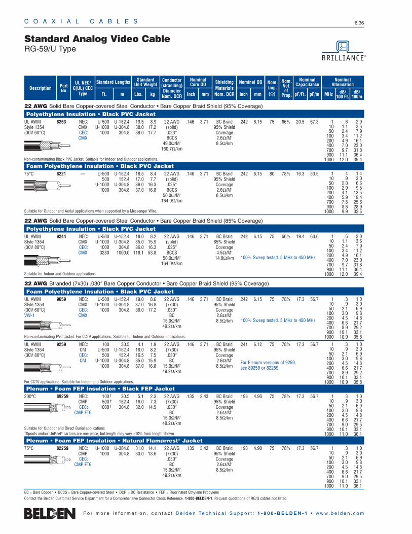
C O A X I A L C A B L E S 6.36
F o r m o r e i n f o r m a t i o n , c o n t a c t B e l d e n Te c h n i c a l S u p p o r t : 1 - 8 0 0 - B E L D E N - 1 • w w w . b e l d e n . c o m
22 AWG Solid Bare Copper-covered Steel Conductor • Bare Copper Braid Shield (95% Coverage)
Polyethylene Insulation • Black PVC JacketUL AWM 8263 NEC: U-500 U-152.4 19.5 8.9 22 AWG .146 3.71 BC Braid .242 6.15 75 66% 20.5 67.3Style 1354 CMX U-1000 U-304.8 38.0 17.2 (solid) 95% Shield(30V 60°C) CEC: 1000 304.8 39.0 17.7 .023″ Coverage
CMX BCCS 2.6Ω/M′49.0Ω/M′ 8.5Ω/km
160.7Ω/km
Non-contaminating Black PVC Jacket. Suitable for Indoor and Outdoor applications.
Foam Polyethylene Insulation • Black PVC Jacket75°C 8221 — U-500 U-152.4 18.5 8.4 22 AWG .146 3.71 BC Braid .242 6.15 80 78% 16.3 53.5
500 152.4 17.0 7.7 (solid) 95% ShieldU-1000 U-304.8 36.0 16.3 .025″ Coverage
1000 304.8 37.0 16.8 BCCS 2.6Ω/M′50.0Ω/M′ 8.5Ω/km
164.0Ω/km
Suitable for Outdoor and Aerial applications when supported by a Messenger Wire.
22 AWG Solid Bare Copper-covered Steel Conductor • Bare Copper Braid Shield (85% Coverage)
Polyethylene Insulation • Black PVC JacketUL AWM 9244 NEC: U-500 U-152.4 18.0 8.2 22 AWG .146 3.71 BC Braid .242 6.15 75 66% 19.4 63.6Style 1354 CMX U-1000 U-304.8 35.0 15.9 (solid) 85% Shield(30V 80°C) CEC: 1000 304.8 36.0 16.3 .025″ Coverage
CMX 3280 1000.0 118.1 53.8 BCCS 4.5Ω/M′50.0Ω/M′ 14.8Ω/km
164.0Ω/km
Suitable for Indoor and Outdoor applications.
22 AWG Stranded (7x30) .030″ Bare Copper Conductor • Bare Copper Braid Shield (95% Coverage)
Foam Polyethylene Insulation • Black PVC JacketUL AWM 9659 NEC: U-500 U-152.4 19.0 8.6 22 AWG .146 3.71 BC Braid .242 6.15 75 78% 17.3 56.7Style 1354 CMX U-1000 U-304.8 37.0 16.8 (7x30) 95% Shield(30V 60°C) CEC: 1000 304.8 38.0 17.2 .030″ CoverageVW-1 CMX BC 2.6Ω/M′
15.0Ω/M′ 8.5Ω/km49.2Ω/km
Non-contaminating PVC Jacket. For CCTV applications. Suitable for Indoor and Outdoor applications.
UL AWM 9259 NEC: 100 30.5 4.1 1.9 22 AWG .146 3.71 BC Braid .241 6.12 75 78% 17.3 56.7Style 1354 CM U-500 U-152.4 18.0 8.2 (7x30) 95% Shield(30V 80°C) CEC: 500 152.4 16.5 7.5 .030″ Coverage
CM U-1000 U-304.8 35.0 15.9 BC 2.6Ω/M′1000 304.8 37.0 16.8 15.0Ω/M′ 8.5Ω/km
49.2Ω/km
For CCTV applications. Suitable for Indoor and Outdoor applications.
Plenum • Foam FEP Insulation • Black FEP Jacket200°C 89259 NEC: 100 † 30.5 5.1 2.3 22 AWG .135 3.43 BC Braid .193 4.90 75 78% 17.3 56.7
CMP 500 † 152.4 16.0 7.3 (7x30) 95% ShieldCEC: 1000 † 304.8 32.0 14.5 .030″ Coverage
CMP FT6 BC 2.6Ω/M′15.0Ω/M′ 8.5Ω/km49.2Ω/km
Suitable for Outdoor and Direct Burial applications.†Spools and/or UnReel® cartons are one piece, but length may vary ±10% from length shown.
Plenum • Foam FEP Insulation • Natural Flamarrest® Jacket75°C 82259 NEC: U-1000 U-304.8 31.0 14.1 22 AWG .135 3.43 BC Braid .193 4.90 75 78% 17.3 56.7
CMP 1000 304.8 30.0 13.6 (7x30) 95% ShieldCEC: .030″ Coverage
CMP FT6 BC 2.6Ω/M′15.0Ω/M′ 8.5Ω/km49.2Ω/km
BC = Bare Copper • BCCS = Bare Copper-covered Steel • DCR = DC Resistance • FEP = Fluorinated Ethylene PropyleneContact the Belden Customer Service Department for a Comprehensive Connector Cross Reference. 1-800-BELDEN-1. Request quotations of RG/U cables not listed.
Standard Analog Video CableRG-59/U Type
1 .4 1.410 .9 3.050 2.0 6.6
100 2.9 9.5200 4.1 13.5400 5.9 19.4700 7.8 25.6900 8.8 28.9
1000 9.9 32.5
1 .3 1.010 .9 3.050 2.1 6.9
100 3.0 9.8200 4.5 14.8400 6.6 21.7700 8.9 29.2900 10.1 33.1
1000 10.9 35.8
1 .3 1.010 .9 3.050 2.1 6.9
100 3.0 9.8200 4.5 14.8400 6.6 21.7700 8.9 29.2900 10.1 33.1
1000 10.9 35.8
For Plenum versions of 9259, see 89259 or 82259.
1 .3 1.010 .9 3.050 2.1 6.9
100 3.0 9.8200 4.5 14.8400 6.6 21.7700 9.0 29.5900 10.1 33.1
1000 11.0 36.1
1 .3 1.010 .9 3.050 2.1 6.9
100 3.0 9.8200 4.5 14.8400 6.6 21.7700 9.0 29.5900 10.1 33.1
1000 11.0 36.1
100% Sweep tested. 5 MHz to 450 MHz.
100% Sweep tested. 5 MHz to 450 MHz.
1 .6 2.010 1.1 3.650 2.4 7.9
100 3.4 11.2200 4.9 16.1400 7.0 23.0700 9.7 31.8900 11.1 36.4
1000 12.0 39.4
ShieldingMaterialsNom. DCR
Nom.Imp.(Ω)
Nominal Core OD Nominal OD
Inch mm Inch mm
Conductor(stranding)DiameterNom. DCR
StandardUnit WeightStandard Lengths
Lbs. kgFt. m
UL NEC/C(UL) CEC
Type
PartNo.
MHz dB/100 Ft.
dB/100m
Nominal Attenuation
Nominal Capacitance
pF/mpF/Ft.
Nom.Vel.of
Prop.Description
1 .6 2.010 1.1 3.650 2.4 7.9
100 3.4 11.2200 4.9 16.1400 7.0 23.0700 9.7 31.8900 11.1 36.4
1000 12.0 39.4
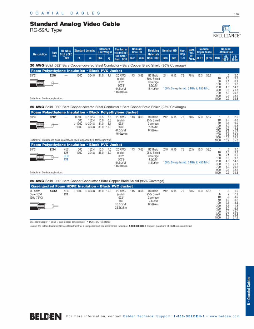
20 AWG Solid .032″ Bare Copper-covered Steel Conductor • Bare Copper Braid Shield (80% Coverage)
Foam Polyethylene Insulation • Black PVC Jacket75°C 9240 — 1000 304.8 31.0 14.1 20 AWG .143 3.63 BC Braid .241 6.12 75 78% 17.3 56.7
(solid) 80% Shield.032″ CoverageBCCS 5.6Ω/M′
44.5Ω/M′ 18.4Ω/km146.0Ω/km
Suitable for Outdoor applications.
20 AWG Solid .032″ Bare Copper-covered Steel Conductor • Bare Copper Braid Shield (95% Coverage)
Foam Polyethylene Insulation • Black Polyethylene Jacket80°C 8212 — U-500 U-152.4 16.5 7.5 20 AWG .143 3.63 BC Braid .242 6.15 75 78% 17.3 56.7
500 152.4 15.0 6.8 (solid) 95% ShieldU-1000 U-304.8 31.0 14.1 .032″ Coverage
1000 304.8 33.0 15.0 BCCS 2.6Ω/M′44.5Ω/M′ 8.5Ω/km
146.0Ω/km
Suitable for Outdoor and Aerial applications when supported by a Messenger Wire.
Foam Polyethylene Insulation • Black PVC Jacket80°C 9274 NEC: 500 152.4 15.5 7.0 20 AWG .143 3.63 BC Braid .240 6.10 75 82% 16.3 53.5
CM 1000 304.8 35.0 15.9 (solid) 95% ShieldCEC: .032″ CoverageCM BCCS 3.5Ω/M′
44.5Ω/M′ 11.5Ω/km146.0Ω/km
Suitable for Outdoor applications.
20 AWG Solid .032″ Bare Copper Conductor • Bare Copper Braid Shield (95% Coverage)
Gas-injected Foam HDPE Insulation • Black PVC JacketUL AWM 1426A NEC: U-1000 U-304.8 35.0 15.9 20 AWG .145 3.68 BC Braid .242 6.15 75 83% 16.3 53.5Style 1354 CM (solid) 95% Shield(30V 75°C) .032″ Coverage
BC 2.6Ω/M10.0Ω/M′ 8.5Ω/km32.8Ω/km
BC = Bare Copper • BCCS = Bare Copper-covered Steel • DCR = DC Resistance
Contact the Belden Customer Service Department for a Comprehensive Connector Cross Reference. 1-800-BELDEN-1. Request quotations of RG/U cables not listed.
C O A X I A L C A B L E S 6.37
6 •
Coax
ial C
able
s
F o r m o r e i n f o r m a t i o n , c o n t a c t B e l d e n Te c h n i c a l S u p p o r t : 1 - 8 0 0 - B E L D E N - 1 • w w w . b e l d e n . c o m
Standard Analog Video CableRG-59/U Type
1 .6 2.010 1.0 3.350 2.1 6.9
100 3.0 9.8200 4.5 14.8400 6.6 21.7700 8.9 29.2900 10.1 33.1
1000 10.9 35.8
1 .6 2.010 1.0 3.350 2.1 6.9
100 3.0 9.8200 4.5 14.8400 6.6 21.7700 8.9 29.2900 10.1 33.1
1000 10.9 35.8
1 .6 2.010 1.0 3.350 2.1 6.9
100 3.0 9.8200 4.5 14.8400 6.6 21.7700 8.9 29.2900 10.1 33.1
1000 10.9 35.8
100% Sweep tested. 5 MHz to 850 MHz.
100% Sweep tested. 5 MHz to 450 MHz.
ShieldingMaterialsNom. DCR
Nom.Imp.(Ω)
Nominal Core OD Nominal OD
Inch mm Inch mm
Conductor(stranding)DiameterNom. DCR
StandardUnit WeightStandard Lengths
Lbs. kgFt. m
UL NEC/C(UL) CEC
Type
PartNo.
MHz dB/100 Ft.
dB/100m
Nominal Attenuation
Nominal Capacitance
pF/mpF/Ft.
Nom.Vel.of
Prop.Description
1 .3 1.05 .7 2.1
10 .9 3.050 1.9 6.2
100 2.6 8.5200 3.6 11.8400 5.0 16.4700 7.0 23.0900 8.0 26.3
1000 8.5 27.9
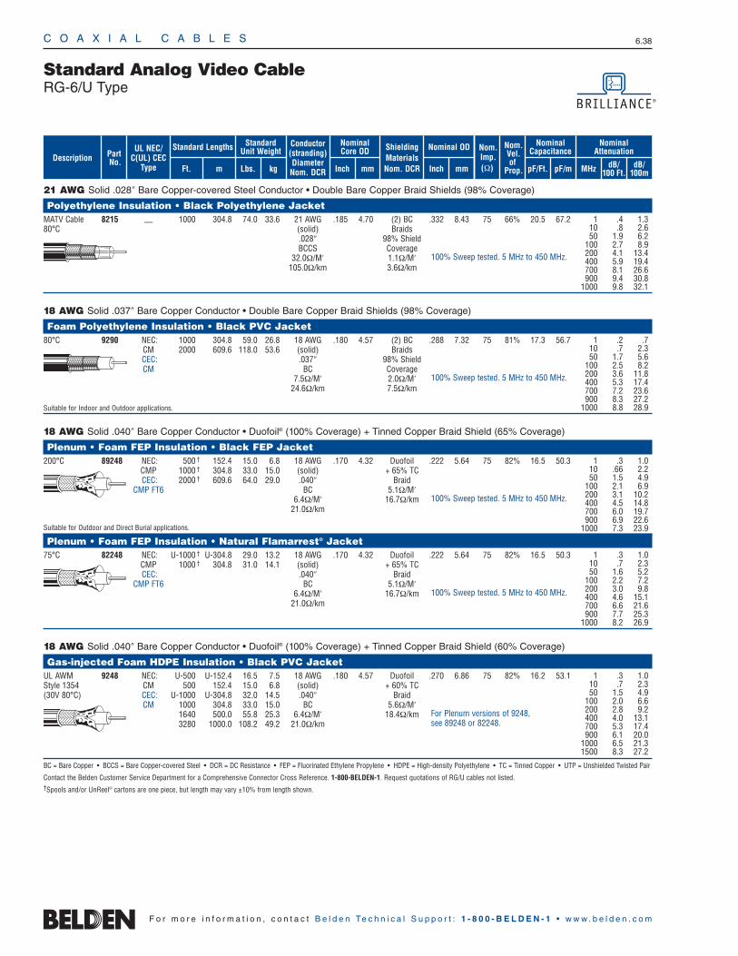
C O A X I A L C A B L E S 6.38
F o r m o r e i n f o r m a t i o n , c o n t a c t B e l d e n Te c h n i c a l S u p p o r t : 1 - 8 0 0 - B E L D E N - 1 • w w w . b e l d e n . c o m
21 AWG Solid .028″ Bare Copper-covered Steel Conductor • Double Bare Copper Braid Shields (98% Coverage)
Polyethylene Insulation • Black Polyethylene JacketMATV Cable 8215 — 1000 304.8 74.0 33.6 21 AWG .185 4.70 (2) BC .332 8.43 75 66% 20.5 67.280°C (solid) Braids
.028″ 98% ShieldBCCS Coverage
32.0Ω/M′ 1.1Ω/M′105.0Ω/km 3.6Ω/km
18 AWG Solid .037″ Bare Copper Conductor • Double Bare Copper Braid Shields (98% Coverage)
Foam Polyethylene Insulation • Black PVC Jacket80°C 9290 NEC: 1000 304.8 59.0 26.8 18 AWG .180 4.57 (2) BC .288 7.32 75 81% 17.3 56.7
CM 2000 609.6 118.0 53.6 (solid) BraidsCEC: .037″ 98% ShieldCM BC Coverage
7.5Ω/M′ 2.0Ω/M′24.6Ω/km 7.5Ω/km
Suitable for Indoor and Outdoor applications.
18 AWG Solid .040″ Bare Copper Conductor • Duofoil® (100% Coverage) + Tinned Copper Braid Shield (65% Coverage)
Plenum • Foam FEP Insulation • Black FEP Jacket200°C 89248 NEC: 500 † 152.4 15.0 6.8 18 AWG .170 4.32 Duofoil .222 5.64 75 82% 16.5 50.3
CMP 1000 † 304.8 33.0 15.0 (solid) + 65% TCCEC: 2000 † 609.6 64.0 29.0 .040″ Braid
CMP FT6 BC 5.1Ω/M′6.4Ω/M′ 16.7Ω/km
21.0Ω/km
Suitable for Outdoor and Direct Burial applications.
Plenum • Foam FEP Insulation • Natural Flamarrest® Jacket75°C 82248 NEC: U-1000 † U-304.8 29.0 13.2 18 AWG .170 4.32 Duofoil .222 5.64 75 82% 16.5 50.3
CMP 1000 † 304.8 31.0 14.1 (solid) + 65% TCCEC: .040″ Braid
CMP FT6 BC 5.1Ω/M′6.4Ω/M′ 16.7Ω/km
21.0Ω/km
18 AWG Solid .040″ Bare Copper Conductor • Duofoil® (100% Coverage) + Tinned Copper Braid Shield (60% Coverage)
Gas-injected Foam HDPE Insulation • Black PVC JacketUL AWM 9248 NEC: U-500 U-152.4 16.5 7.5 18 AWG .180 4.57 Duofoil .270 6.86 75 82% 16.2 53.1Style 1354 CM 500 152.4 15.0 6.8 (solid) + 60% TC(30V 80°C) CEC: U-1000 U-304.8 32.0 14.5 .040″ Braid
CM 1000 304.8 33.0 15.0 BC 5.6Ω/M′1640 500.0 55.8 25.3 6.4Ω/M′ 18.4Ω/km3280 1000.0 108.2 49.2 21.0Ω/km
BC = Bare Copper • BCCS = Bare Copper-covered Steel • DCR = DC Resistance • FEP = Fluorinated Ethylene Propylene • HDPE = High-density Polyethylene • TC = Tinned Copper • UTP = Unshielded Twisted Pair
Contact the Belden Customer Service Department for a Comprehensive Connector Cross Reference. 1-800-BELDEN-1. Request quotations of RG/U cables not listed.†Spools and/or UnReel® cartons are one piece, but length may vary ±10% from length shown.
Standard Analog Video CableRG-6/U Type
1 .4 1.310 .8 2.650 1.9 6.2
100 2.7 8.9200 4.1 13.4400 5.9 19.4700 8.1 26.6900 9.4 30.8
1000 9.8 32.1
1 .2 .710 .7 2.350 1.7 5.6
100 2.5 8.2200 3.6 11.8400 5.3 17.4700 7.2 23.6900 8.3 27.2
1000 8.8 28.9
1 .3 1.010 .7 2.350 1.5 4.9
100 2.0 6.6200 2.8 9.2400 4.0 13.1700 5.3 17.4900 6.1 20.0
1000 6.5 21.31500 8.3 27.2
1 .3 1.010 .7 2.350 1.6 5.2
100 2.2 7.2200 3.0 9.8400 4.6 15.1700 6.6 21.6900 7.7 25.3
1000 8.2 26.9
1 .3 1.010 .66 2.250 1.5 4.9
100 2.1 6.9200 3.1 10.2400 4.5 14.8700 6.0 19.7900 6.9 22.6
1000 7.3 23.9
For Plenum versions of 9248, see 89248 or 82248.
100% Sweep tested. 5 MHz to 450 MHz.
100% Sweep tested. 5 MHz to 450 MHz.
100% Sweep tested. 5 MHz to 450 MHz.
100% Sweep tested. 5 MHz to 450 MHz.
ShieldingMaterialsNom. DCR
Nom.Imp.(Ω)
Nominal Core OD Nominal OD
Inch mm Inch mm
Conductor(stranding)DiameterNom. DCR
StandardUnit WeightStandard Lengths
Lbs. kgFt. m
UL NEC/C(UL) CEC
Type
PartNo.
MHz dB/100 Ft.
dB/100m
Nominal Attenuation
Nominal Capacitance
pF/mpF/Ft.
Nom.Vel.of
Prop.Description
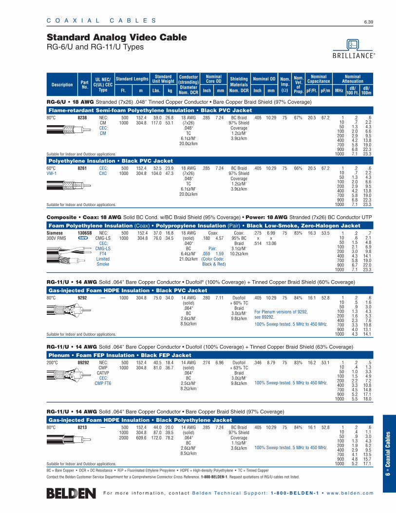
RG-6/U • 18 AWG Stranded (7x26) .048″ Tinned Copper Conductor • Bare Copper Braid Shield (97% Coverage)
Flame-retardant Semi-foam Polyethylene Insulation • Black PVC Jacket80°C 8238 NEC: 500 152.4 59.0 26.8 18 AWG .285 7.24 BC Braid .405 10.29 75 67% 20.5 67.2
CM 1000 304.8 117.0 53.1 (7x26) 97% ShieldCEC: .048″ CoverageCM TC 1.2Ω/M′
6.1Ω/M′ 3.9Ω/km20.0Ω/km
Suitable for Indoor and Outdoor applications.
Polyethylene Insulation • Black PVC Jacket60°C 8261 CEC: 500 152.4 52.5 23.9 18 AWG .285 7.24 BC Braid .405 10.29 75 66% 20.5 67.2VW-1 CXC 1000 304.8 104.0 47.3 (7x26) 97% Shield
.048″ CoverageTC 1.2Ω/M′
6.1Ω/M′ 3.9Ω/km20.0Ω/km
Suitable for Indoor and Outdoor applications.
Composite • Coax: 18 AWG Solid BC Cond. w/BC Braid Shield (95% Coverage) • Power: 18 AWG Stranded (7x26) BC Conductor UTP
Foam Polyethylene Insulation (Coax) • Polypropylene Insulation (Pair) • Black Low-Smoke, Zero-Halogen JacketSiamese 1306SB NEC: 500 152.4 37.0 16.8 18 AWG Coax: Coax: .275 6.99 75 83% 16.3 53.5300V RMS u CMG-LS 1000 304.8 76.0 34.5 (solid) .180 4.57 95% BC x x
CEC: .040″ Braid .514 13.06CMG-LS BC Pair: 3.1Ω/M′
FT4 6.4Ω/M′ .059 1.59 10.2Ω/kmLimited 21.0Ω/km (Color Code: Smoke Black & Red)
RG-11/U • 14 AWG Solid .064″ Bare Copper Conductor • Duofoil® (100% Coverage) + Tinned Copper Braid Shield (60% Coverage)
Gas-injected Foam HDPE Insulation • Black PVC Jacket80°C 9292 — 1000 304.8 75.0 34.0 14 AWG .280 7.11 Duofoil .405 10.29 75 84% 16.1 52.8
(solid) + 60% TC.064″ Braid
BC 3.0Ω/M′2.6Ω/M′ 9.8Ω/km8.5Ω/km
Suitable for Indoor and Outdoor applications.
RG-11/U • 14 AWG Solid .064″ Bare Copper Conductor • Duofoil (100% Coverage) + Tinned Copper Braid Shield (63% Coverage)
Plenum • Foam FEP Insulation • Black FEP Jacket200°C 89292 NEC: 500 152.4 40.5 18.4 14 AWG .274 6.96 Duofoil .346 8.79 75 83% 16.2 53.1
CMP 1000 304.8 81.0 36.7 (solid) + 63% TCCATVP .064″ Braid
CEC: BC 3.0Ω/M′CMP FT6 2.5Ω/M′ 9.8Ω/km
8.2Ω/km
RG-11/U • 14 AWG Solid .064″ Bare Copper Conductor • Bare Copper Braid Shield (97% Coverage)
Gas-injected Foam HDPE Insulation • Black Polyethylene Jacket80°C 8213 — 500 152.4 44.0 20.0 14 AWG .285 7.24 BC Braid .405 10.29 75 84% 16.1 52.8
1000 304.8 87.0 39.5 (solid) 97% Shield2000 609.6 172.0 78.2 .064″ Coverage
BC 1.1Ω/M′2.6Ω/M′ 3.6Ω/km8.5Ω/km
Suitable for Indoor and Outdoor applications.
BC = Bare Copper • DCR = DC Resistance • FEP = Fluorinated Ethylene Propylene • HDPE = High-density Polyethylene • TC = Tinned Copper
Contact the Belden Customer Service Department for a Comprehensive Connector Cross Reference. 1-800-BELDEN-1. Request quotations of RG/U cables not listed.
C O A X I A L C A B L E S 6.39
6 •
Coax
ial C
able
s
F o r m o r e i n f o r m a t i o n , c o n t a c t B e l d e n Te c h n i c a l S u p p o r t : 1 - 8 0 0 - B E L D E N - 1 • w w w . b e l d e n . c o m
Standard Analog Video CableRG-6/U and RG-11/U Types
1 .2 .610 .7 2.250 1.3 4.3
100 2.0 6.6200 2.9 9.5400 4.2 13.8700 5.8 19.0900 6.8 22.3
1000 7.1 23.3
1 .2 .610 .7 2.250 1.3 4.3
100 2.0 6.6200 2.9 9.5400 4.2 13.8700 5.8 19.0900 6.8 22.3
1000 7.1 23.3
1 .2 .610 .4 1.150 .9 3.0
100 1.3 4.3200 1.9 6.2400 2.9 9.5700 4.1 13.5900 4.8 15.7
1000 5.2 17.1
1 .2 .610 .5 1.650 .9 3.0
100 1.3 4.3200 1.6 5.3400 2.3 7.6700 3.3 10.8900 4.0 13.1
1000 4.3 14.1
1 .2 .510 .4 1.350 1.0 3.3
100 1.5 4.9200 2.2 7.2400 3.3 10.8700 4.5 14.8900 5.2 17.1
1000 5.5 18.0
For Plenum versions of 9292, see 89292.
100% Sweep tested. 5 MHz to 450 MHz.
100% Sweep tested. 5 MHz to 450 MHz.
100% Sweep tested. 5 MHz to 450 MHz.
1 .2 .710 .6 2.150 1.5 4.8
100 2.1 6.9200 3.0 9.8400 4.3 14.1700 5.8 19.0900 6.7 22.0
1000 7.1 23.3
ShieldingMaterialsNom. DCR
Nom.Imp.(Ω)
Nominal Core OD Nominal OD
Inch mm Inch mm
Conductor(stranding)DiameterNom. DCR
StandardUnit WeightStandard Lengths
Lbs. kgFt. m
UL NEC/C(UL) CEC
Type
PartNo.
MHz dB/100 Ft.
dB/100m
Nominal Attenuation
Nominal Capacitance
pF/mpF/Ft.
Nom.Vel.of
Prop.Description
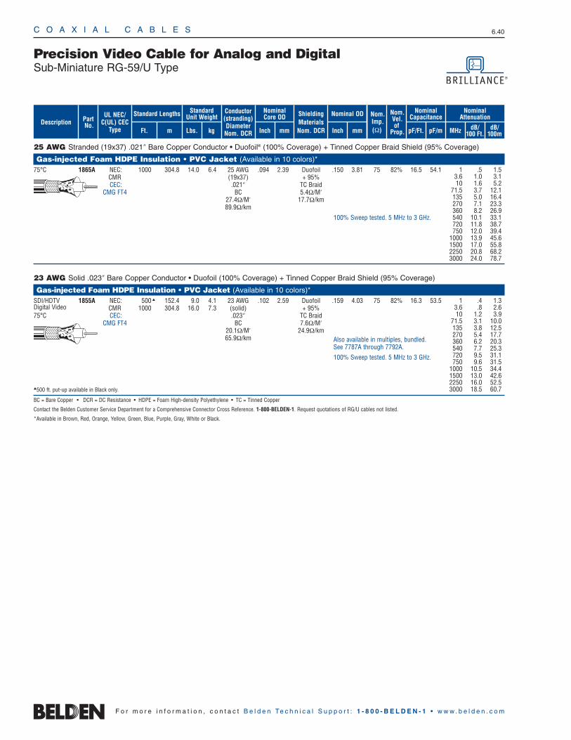
C O A X I A L C A B L E S 6.40
F o r m o r e i n f o r m a t i o n , c o n t a c t B e l d e n Te c h n i c a l S u p p o r t : 1 - 8 0 0 - B E L D E N - 1 • w w w . b e l d e n . c o m
25 AWG Stranded (19x37) .021″ Bare Copper Conductor • Duofoil® (100% Coverage) + Tinned Copper Braid Shield (95% Coverage)
Gas-injected Foam HDPE Insulation • PVC Jacket (Available in 10 colors)*75°C 1865A NEC: 1000 304.8 14.0 6.4 25 AWG .094 2.39 Duofoil .150 3.81 75 82% 16.5 54.1
CMR (19x37) + 95%CEC: .021″ TC Braid
CMG FT4 BC 5.4Ω/M′27.4Ω/M′ 17.7Ω/km89.9Ω/km
23 AWG Solid .023″ Bare Copper Conductor • Duofoil (100% Coverage) + Tinned Copper Braid Shield (95% Coverage)
Gas-injected Foam HDPE Insulation • PVC Jacket (Available in 10 colors)*SDI/HDTV 1855A NEC: 500 152.4 9.0 4.1 23 AWG .102 2.59 Duofoil .159 4.03 75 82% 16.3 53.5Digital Video CMR 1000 304.8 16.0 7.3 (solid) + 95%75°C CEC: .023″ TC Braid
CMG FT4 BC 7.6Ω/M′20.1Ω/M′ 24.9Ω/km65.9Ω/km
500 ft. put-up available in Black only.
BC = Bare Copper • DCR = DC Resistance • HDPE = Foam High-density Polyethylene • TC = Tinned Copper
Contact the Belden Customer Service Department for a Comprehensive Connector Cross Reference. 1-800-BELDEN-1. Request quotations of RG/U cables not listed.
*Available in Brown, Red, Orange, Yellow, Green, Blue, Purple, Gray, White or Black.
Precision Video Cable for Analog and DigitalSub-Miniature RG-59/U Type
1 .5 1.53.6 1.0 3.110 1.6 5.2
71.5 3.7 12.1135 5.0 16.4270 7.1 23.3360 8.2 26.9540 10.1 33.1720 11.8 38.7750 12.0 39.4
1000 13.9 45.61500 17.0 55.82250 20.8 68.23000 24.0 78.7
1 .4 1.33.6 .8 2.610 1.2 3.9
71.5 3.1 10.0135 3.8 12.5270 5.4 17.7360 6.2 20.3540 7.7 25.3720 9.5 31.1750 9.6 31.5
1000 10.5 34.41500 13.0 42.62250 16.0 52.53000 18.5 60.7
Also available in multiples, bundled. See 7787A through 7792A.
100% Sweep tested. 5 MHz to 3 GHz.
100% Sweep tested. 5 MHz to 3 GHz.
ShieldingMaterialsNom. DCR
Nom.Imp.(Ω)
Nominal Core OD Nominal OD
Inch mm Inch mm
Conductor(stranding)DiameterNom. DCR
StandardUnit WeightStandard Lengths
Lbs. kgFt. m
UL NEC/C(UL) CEC
Type
PartNo.
MHz dB/100 Ft.
dB/100m
Nominal Attenuation
Nominal Capacitance
pF/mpF/Ft.
Nom.Vel.of
Prop.Description
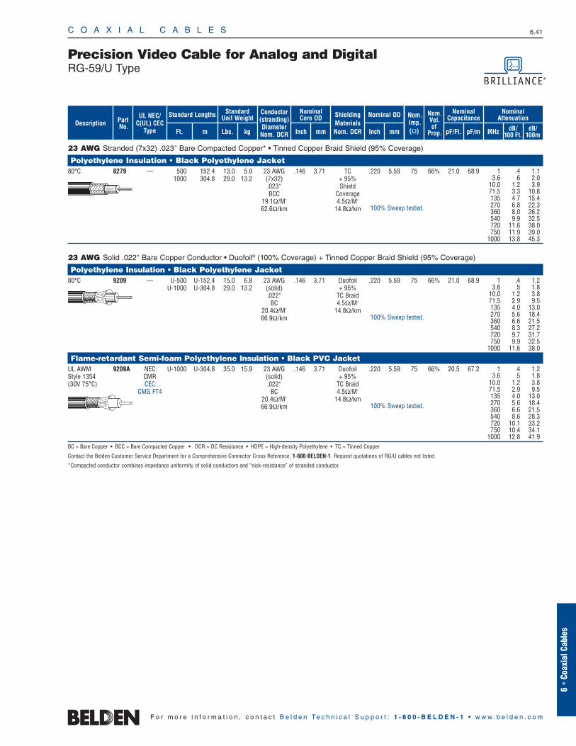
23 AWG Stranded (7x32) .023″ Bare Compacted Copper* • Tinned Copper Braid Shield (95% Coverage)
Polyethylene Insulation • Black Polyethylene Jacket80°C 8279 — 500 152.4 13.0 5.9 23 AWG .146 3.71 TC .220 5.59 75 66% 21.0 68.9
1000 304.8 29.0 13.2 (7x32) + 95% .023″ ShieldBCC Coverage
19.1Ω/M′ 4.5Ω/M′62.6Ω/km 14.8Ω/km
23 AWG Solid .022″ Bare Copper Conductor • Duofoil® (100% Coverage) + Tinned Copper Braid Shield (95% Coverage)
Polyethylene Insulation • Black Polyethylene Jacket80°C 9209 — U-500 U-152.4 15.0 6.8 23 AWG .146 3.71 Duofoil .220 5.59 75 66% 21.0 68.9
U-1000 U-304.8 29.0 13.2 (solid) + 95%.022″ TC Braid
BC 4.5Ω/M′20.4Ω/M′ 14.8Ω/km66.9Ω/km
Flame-retardant Semi-foam Polyethylene Insulation • Black PVC JacketUL AWM 9209A NEC: U-1000 U-304.8 35.0 15.9 23 AWG .146 3.71 Duofoil .220 5.59 75 66% 20.5 67.2Style 1354 CMR (solid) + 95%(30V 75°C) CEC: .022″ TC Braid
CMG FT4 BC 4.5Ω/M′20.4Ω/M′ 14.8Ω/km66.9Ω/km
BC = Bare Copper • BCC = Bare Compacted Copper • DCR = DC Resistance • HDPE = High-density Polyethylene • TC = Tinned Copper
Contact the Belden Customer Service Department for a Comprehensive Connector Cross Reference. 1-800-BELDEN-1. Request quotations of RG/U cables not listed.
*Compacted conductor combines impedance uniformity of solid conductors and “nick-resistance” of stranded conductor.
C O A X I A L C A B L E S 6.41
6 •
Coax
ial C
able
s
F o r m o r e i n f o r m a t i o n , c o n t a c t B e l d e n Te c h n i c a l S u p p o r t : 1 - 8 0 0 - B E L D E N - 1 • w w w . b e l d e n . c o m
Precision Video Cable for Analog and DigitalRG-59/U Type
1 .4 1.13.6 .6 2.0
10.0 1.2 3.971.5 3.3 10.8135 4.7 15.4270 6.8 22.3360 8.0 26.2540 9.9 32.5720 11.6 38.0750 11.9 39.0
1000 13.8 45.3
1 .4 1.23.6 .5 1.8
10.0 1.2 3.871.5 2.9 9.5135 4.0 13.0270 5.6 18.4360 6.6 21.5540 8.3 27.2720 9.7 31.7750 9.9 32.5
1000 11.6 38.0
1 .4 1.23.6 .5 1.8
10.0 1.2 3.871.5 2.9 9.5135 4.0 13.0270 5.6 18.4360 6.6 21.5540 8.6 28.3720 10.1 33.2750 10.4 34.1
1000 12.8 41.9
100% Sweep tested.
100% Sweep tested.
100% Sweep tested.
ShieldingMaterialsNom. DCR
Nom.Imp.(Ω)
Nominal Core OD Nominal OD
Inch mm Inch mm
Conductor(stranding)DiameterNom. DCR
StandardUnit WeightStandard Lengths
Lbs. kgFt. m
UL NEC/C(UL) CEC
Type
PartNo.
MHz dB/100 Ft.
dB/100m
Nominal Attenuation
Nominal Capacitance
pF/mpF/Ft.
Nom.Vel.of
Prop.Description
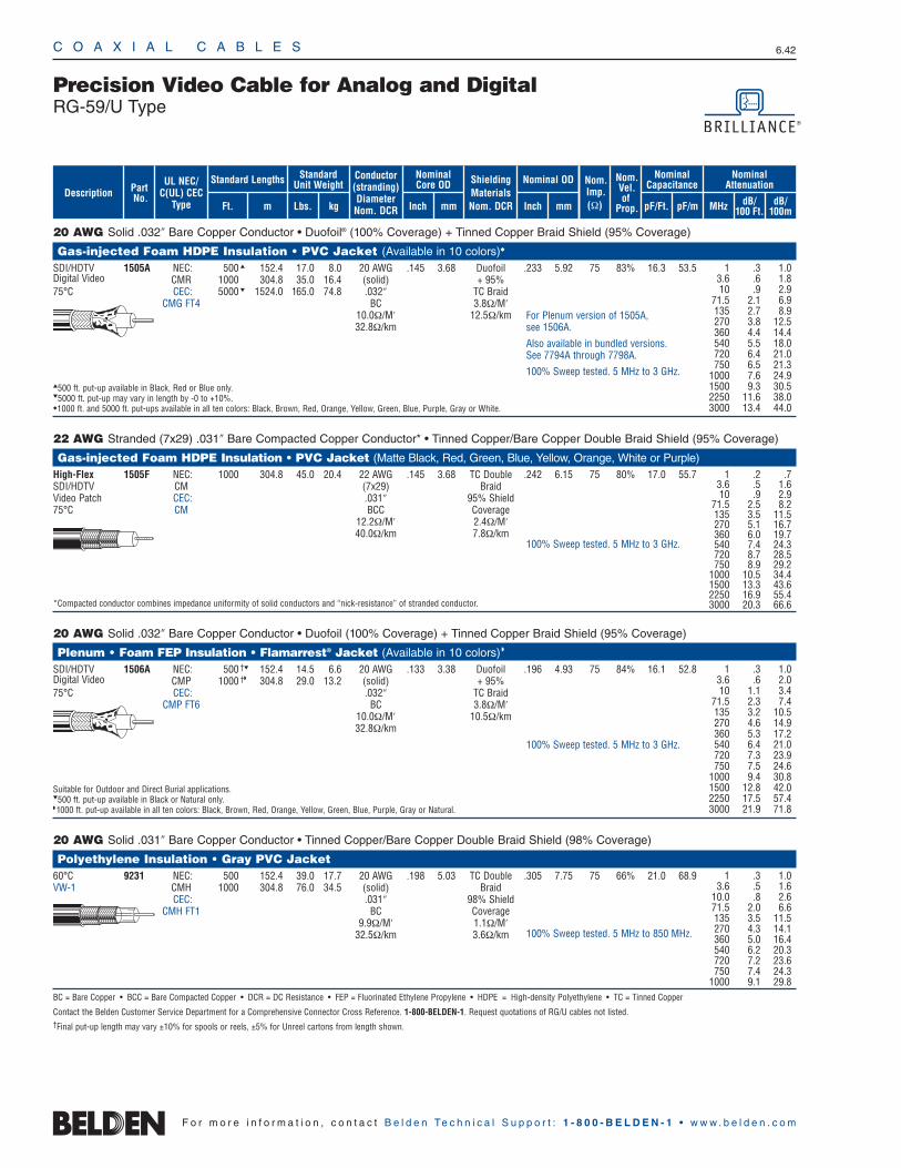
C O A X I A L C A B L E S 6.42
F o r m o r e i n f o r m a t i o n , c o n t a c t B e l d e n Te c h n i c a l S u p p o r t : 1 - 8 0 0 - B E L D E N - 1 • w w w . b e l d e n . c o m
20 AWG Solid .032″ Bare Copper Conductor • Duofoil® (100% Coverage) + Tinned Copper Braid Shield (95% Coverage)
Gas-injected Foam HDPE Insulation • PVC Jacket (Available in 10 colors)
SDI/HDTV 1505A NEC: 500 152.4 17.0 8.0 20 AWG .145 3.68 Duofoil .233 5.92 75 83% 16.3 53.5Digital Video CMR 1000 304.8 35.0 16.4 (solid) + 95%75°C CEC: 5000 1524.0 165.0 74.8 .032″ TC Braid
CMG FT4 BC 3.8Ω/M′10.0Ω/M′ 12.5Ω/km32.8Ω/km
500 ft. put-up available in Black, Red or Blue only.5000 ft. put-up may vary in length by -0 to +10%.1000 ft. and 5000 ft. put-ups available in all ten colors: Black, Brown, Red, Orange, Yellow, Green, Blue, Purple, Gray or White.
22 AWG Stranded (7x29) .031″ Bare Compacted Copper Conductor* • Tinned Copper/Bare Copper Double Braid Shield (95% Coverage)
Gas-injected Foam HDPE Insulation • PVC Jacket (Matte Black, Red, Green, Blue, Yellow, Orange, White or Purple)High-Flex 1505F NEC: 1000 304.8 45.0 20.4 22 AWG .145 3.68 TC Double .242 6.15 75 80% 17.0 55.7SDI/HDTV CM (7x29) BraidVideo Patch CEC: .031″ 95% Shield75°C CM BCC Coverage
12.2Ω/M′ 2.4Ω/M′40.0Ω/km 7.8Ω/km
*Compacted conductor combines impedance uniformity of solid conductors and “nick-resistance” of stranded conductor.
20 AWG Solid .032″ Bare Copper Conductor • Duofoil (100% Coverage) + Tinned Copper Braid Shield (95% Coverage)
Plenum • Foam FEP Insulation • Flamarrest® Jacket (Available in 10 colors)
SDI/HDTV 1506A NEC: 500 † 152.4 14.5 6.6 20 AWG .133 3.38 Duofoil .196 4.93 75 84% 16.1 52.8Digital Video CMP 1000 † 304.8 29.0 13.2 (solid) + 95%75°C CEC: .032″ TC Braid
CMP FT6 BC 3.8Ω/M′10.0Ω/M′ 10.5Ω/km32.8Ω/km
Suitable for Outdoor and Direct Burial applications.500 ft. put-up available in Black or Natural only. 1000 ft. put-up available in all ten colors: Black, Brown, Red, Orange, Yellow, Green, Blue, Purple, Gray or Natural.
20 AWG Solid .031″ Bare Copper Conductor • Tinned Copper/Bare Copper Double Braid Shield (98% Coverage)
Polyethylene Insulation • Gray PVC Jacket60°C 9231 NEC: 500 152.4 39.0 17.7 20 AWG .198 5.03 TC Double .305 7.75 75 66% 21.0 68.9VW-1 CMH 1000 304.8 76.0 34.5 (solid) Braid
CEC: .031″ 98% ShieldCMH FT1 BC Coverage
9.9Ω/M′ 1.1Ω/M′32.5Ω/km 3.6Ω/km
BC = Bare Copper • BCC = Bare Compacted Copper • DCR = DC Resistance • FEP = Fluorinated Ethylene Propylene • HDPE = High-density Polyethylene • TC = Tinned Copper
Contact the Belden Customer Service Department for a Comprehensive Connector Cross Reference. 1-800-BELDEN-1. Request quotations of RG/U cables not listed.†Final put-up length may vary ±10% for spools or reels, ±5% for Unreel cartons from length shown.
Precision Video Cable for Analog and DigitalRG-59/U Type
1 .3 1.03.6 .5 1.6
10.0 .8 2.671.5 2.0 6.6135 3.5 11.5270 4.3 14.1360 5.0 16.4540 6.2 20.3720 7.2 23.6750 7.4 24.3
1000 9.1 29.8
100% Sweep tested. 5 MHz to 850 MHz.
1 .3 1.03.6 .6 1.810 .9 2.9
71.5 2.1 6.9135 2.7 8.9270 3.8 12.5360 4.4 14.4540 5.5 18.0720 6.4 21.0750 6.5 21.3
1000 7.6 24.91500 9.3 30.52250 11.6 38.03000 13.4 44.0
1 .3 1.03.6 .6 2.010 1.1 3.4
71.5 2.3 7.4135 3.2 10.5270 4.6 14.9360 5.3 17.2540 6.4 21.0720 7.3 23.9750 7.5 24.6
1000 9.4 30.81500 12.8 42.02250 17.5 57.43000 21.9 71.8
For Plenum version of 1505A, see 1506A.
Also available in bundled versions. See 7794A through 7798A.
100% Sweep tested. 5 MHz to 3 GHz.
100% Sweep tested. 5 MHz to 3 GHz.
ShieldingMaterialsNom. DCR
Nom.Imp.(Ω)
Nominal Core OD Nominal OD
Inch mm Inch mm
Conductor(stranding)DiameterNom. DCR
StandardUnit WeightStandard Lengths
Lbs. kgFt. m
UL NEC/C(UL) CEC
Type
PartNo.
MHz dB/100 Ft.
dB/100m
Nominal Attenuation
Nominal Capacitance
pF/mpF/Ft.
Nom.Vel.of
Prop.Description
1 .2 .73.6 .5 1.610 .9 2.9
71.5 2.5 8.2135 3.5 11.5270 5.1 16.7360 6.0 19.7540 7.4 24.3720 8.7 28.5750 8.9 29.2
1000 10.5 34.41500 13.3 43.62250 16.9 55.43000 20.3 66.6
100% Sweep tested. 5 MHz to 3 GHz.
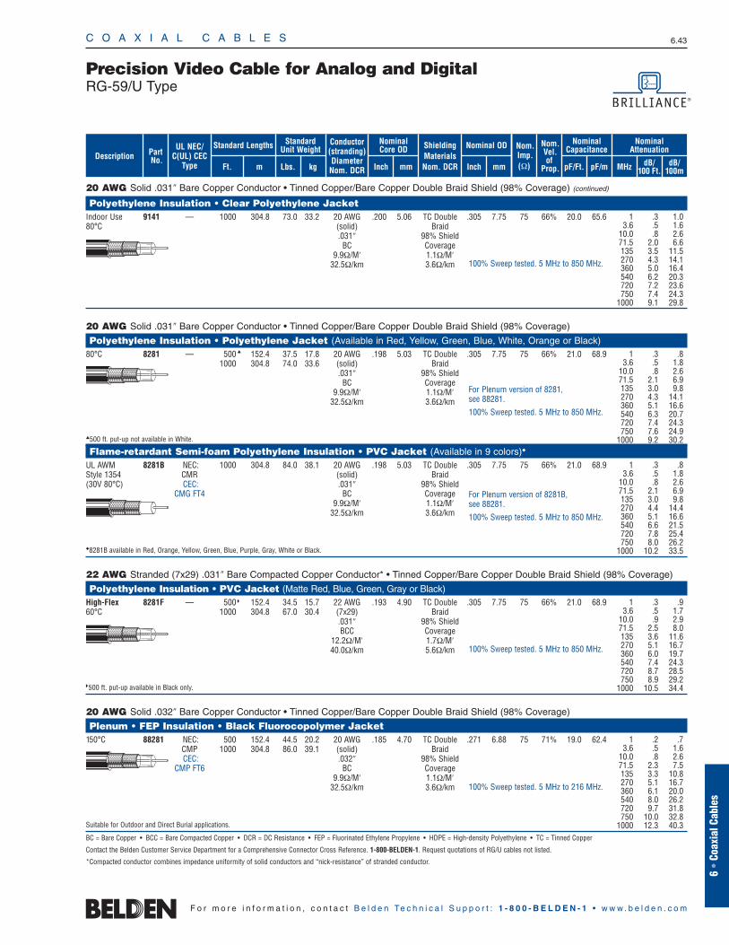
20 AWG Solid .031″ Bare Copper Conductor • Tinned Copper/Bare Copper Double Braid Shield (98% Coverage) (continued)
Polyethylene Insulation • Clear Polyethylene JacketIndoor Use 9141 — 1000 304.8 73.0 33.2 20 AWG .200 5.06 TC Double .305 7.75 75 66% 20.0 65.680°C (solid) Braid
.031″ 98% ShieldBC Coverage
9.9Ω/M′ 1.1Ω/M′32.5Ω/km 3.6Ω/km
20 AWG Solid .031″ Bare Copper Conductor • Tinned Copper/Bare Copper Double Braid Shield (98% Coverage)
Polyethylene Insulation • Polyethylene Jacket (Available in Red, Yellow, Green, Blue, White, Orange or Black)80°C 8281 — 500 152.4 37.5 17.8 20 AWG .198 5.03 TC Double .305 7.75 75 66% 21.0 68.9
1000 304.8 74.0 33.6 (solid) Braid.031″ 98% Shield
BC Coverage9.9Ω/M′ 1.1Ω/M′
32.5Ω/km 3.6Ω/km
500 ft. put-up not available in White.
Flame-retardant Semi-foam Polyethylene Insulation • PVC Jacket (Available in 9 colors)
UL AWM 8281B NEC: 1000 304.8 84.0 38.1 20 AWG .198 5.03 TC Double .305 7.75 75 66% 21.0 68.9Style 1354 CMR (solid) Braid(30V 80°C) CEC: .031″ 98% Shield
CMG FT4 BC Coverage9.9Ω/M′ 1.1Ω/M′
32.5Ω/km 3.6Ω/km
8281B available in Red, Orange, Yellow, Green, Blue, Purple, Gray, White or Black.
22 AWG Stranded (7x29) .031″ Bare Compacted Copper Conductor* • Tinned Copper/Bare Copper Double Braid Shield (98% Coverage)
Polyethylene Insulation • PVC Jacket (Matte Red, Blue, Green, Gray or Black)High-Flex 8281F — 500 152.4 34.5 15.7 22 AWG .193 4.90 TC Double .305 7.75 75 66% 21.0 68.960°C 1000 304.8 67.0 30.4 (7x29) Braid
.031″ 98% ShieldBCC Coverage
12.2Ω/M′ 1.7Ω/M′40.0Ω/km 5.6Ω/km
500 ft. put-up available in Black only.
20 AWG Solid .032″ Bare Copper Conductor • Tinned Copper/Bare Copper Double Braid Shield (98% Coverage)
Plenum • FEP Insulation • Black Fluorocopolymer Jacket150°C 88281 NEC: 500 152.4 44.5 20.2 20 AWG .185 4.70 TC Double .271 6.88 75 71% 19.0 62.4
CMP 1000 304.8 86.0 39.1 (solid) BraidCEC: .032″ 98% Shield
CMP FT6 BC Coverage9.9Ω/M′ 1.1Ω/M′
32.5Ω/km 3.6Ω/km
Suitable for Outdoor and Direct Burial applications.
BC = Bare Copper • BCC = Bare Compacted Copper • DCR = DC Resistance • FEP = Fluorinated Ethylene Propylene • HDPE = High-density Polyethylene • TC = Tinned Copper
Contact the Belden Customer Service Department for a Comprehensive Connector Cross Reference. 1-800-BELDEN-1. Request quotations of RG/U cables not listed.
*Compacted conductor combines impedance uniformity of solid conductors and “nick-resistance” of stranded conductor.
C O A X I A L C A B L E S 6.43
6 •
Coax
ial C
able
s
F o r m o r e i n f o r m a t i o n , c o n t a c t B e l d e n Te c h n i c a l S u p p o r t : 1 - 8 0 0 - B E L D E N - 1 • w w w . b e l d e n . c o m
Precision Video Cable for Analog and DigitalRG-59/U Type
1 .3 1.03.6 .5 1.6
10.0 .8 2.671.5 2.0 6.6135 3.5 11.5270 4.3 14.1360 5.0 16.4540 6.2 20.3720 7.2 23.6750 7.4 24.3
1000 9.1 29.8
1 .3 .83.6 .5 1.8
10.0 .8 2.671.5 2.1 6.9135 3.0 9.8270 4.3 14.1360 5.1 16.6540 6.3 20.7720 7.4 24.3750 7.6 24.9
1000 9.2 30.2
1 .3 .83.6 .5 1.8
10.0 .8 2.671.5 2.1 6.9135 3.0 9.8270 4.4 14.4360 5.1 16.6540 6.6 21.5720 7.8 25.4750 8.0 26.2
1000 10.2 33.5
1 .2 .73.6 .5 1.6
10.0 .8 2.671.5 2.3 7.5135 3.3 10.8270 5.1 16.7360 6.1 20.0540 8.0 26.2720 9.7 31.8750 10.0 32.8
1000 12.3 40.3
For Plenum version of 8281B, see 88281.
100% Sweep tested. 5 MHz to 850 MHz.
100% Sweep tested. 5 MHz to 850 MHz.
For Plenum version of 8281, see 88281.
100% Sweep tested. 5 MHz to 850 MHz.
1 .3 .93.6 .5 1.7
10.0 .9 2.971.5 2.5 8.0135 3.6 11.6270 5.1 16.7360 6.0 19.7540 7.4 24.3720 8.7 28.5750 8.9 29.2
1000 10.5 34.4
100% Sweep tested. 5 MHz to 850 MHz.
100% Sweep tested. 5 MHz to 216 MHz.
ShieldingMaterialsNom. DCR
Nom.Imp.(Ω)
Nominal Core OD Nominal OD
Inch mm Inch mm
Conductor(stranding)DiameterNom. DCR
StandardUnit WeightStandard Lengths
Lbs. kgFt. m
UL NEC/C(UL) CEC
Type
PartNo.
MHz dB/100 Ft.
dB/100m
Nominal Attenuation
Nominal Capacitance
pF/mpF/Ft.
Nom.Vel.of
Prop.Description
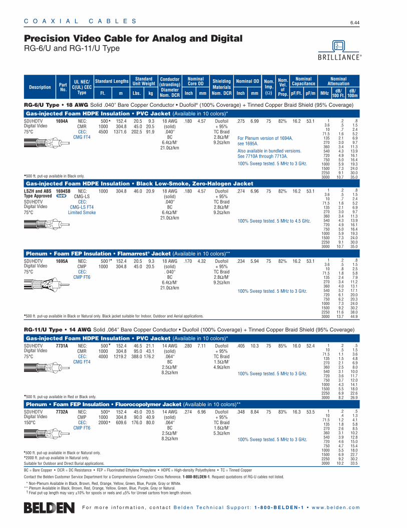
C O A X I A L C A B L E S 6.44
F o r m o r e i n f o r m a t i o n , c o n t a c t B e l d e n Te c h n i c a l S u p p o r t : 1 - 8 0 0 - B E L D E N - 1 • w w w . b e l d e n . c o m
RG-6/U Type • 18 AWG Solid .040″ Bare Copper Conductor • Duofoil® (100% Coverage) + Tinned Copper Braid Shield (95% Coverage)
Gas-injected Foam HDPE Insulation • PVC Jacket (Available in 10 colors)*SDI/HDTV 1694A NEC: 500 152.4 20.5 9.3 18 AWG .180 4.57 Duofoil .275 6.99 75 82% 16.2 53.1Digital Video CMR 1000 304.8 45.0 20.5 (solid) + 95%75°C CEC: 4500 1371.6 202.5 91.9 .040″ TC Braid
CMG FT4 BC 2.8Ω/M′6.4Ω/M′ 9.2Ω/km
21.0Ω/km
500 ft. put-up available in Black only.
Gas-injected Foam HDPE Insulation • Black Low-Smoke, Zero-Halogen Jacket LSZH and ABS 1694SB NEC: 1000 304.8 46.0 20.9 18 AWG .180 4.57 Duofoil .274 6.96 75 82% 16.2 53.1Type Approved u CMG-LS (solid) + 95%SDI/HDTV CEC: .040″ TC BraidDigital Video CMG-LS FT4 BC 2.8Ω/M′75°C Limited Smoke 6.4Ω/M′ 9.2Ω/km
21.0Ω/km
Plenum • Foam FEP Insulation • Flamarrest® Jacket (Available in 10 colors)**SDI/HDTV 1695A NEC: 500 † 152.4 20.5 9.3 18 AWG .170 4.32 Duofoil .234 5.94 75 82% 16.2 53.1Digital Video CMP 1000 304.8 45.0 20.5 (solid) + 95%75°C CEC: . 040″ TC Braid
CMP FT6 BC 2.8Ω/M′6.4Ω/M′ 9.2Ω/km
21.0Ω/km
500 ft. put-up available in Black or Natural only. Black jacket suitable for Indoor, Outdoor and Aerial applications.
RG-11/U Type • 14 AWG Solid .064″ Bare Copper Conductor • Duofoil (100% Coverage) + Tinned Copper Braid Shield (95% Coverage)
Gas-injected Foam HDPE Insulation • PVC Jacket (Available in 10 colors)*SDI/HDTV 7731A NEC: 500 152.4 46.5 21.1 14 AWG .280 7.11 Duofoil .405 10.3 75 85% 16.0 52.4Digital Video CMR 1000 304.8 95.0 43.1 (solid) + 95%75°C CEC: 4000 1219.2 388.0 176.2 .064″ TC Braid
CMG FT4 BC 1.5Ω/M′2.5Ω/M′ 4.9Ω/km8.2Ω/km
500 ft. put-up available in Red or Black only.
Plenum • Foam FEP Insulation • Fluorocopolymer Jacket (Available in 10 colors)**SDI/HDTV 7732A NEC: 500 152.4 45.0 20.5 14 AWG .274 6.96 Duofoil .348 8.84 75 83% 16.3 53.5Digital Video CMP 1000 304.8 90.0 40.9 (solid) + 95%150°C CEC: 2000 609.6 176.0 80.0 .064″ TC Braid
CMP FT6 BC 1.6Ω/M′2.5Ω/M′ 5.3Ω/km8.2Ω/km
500 ft. put-up available in Black or Natural only.2000 ft. put-up available in Natural only. Suitable for Outdoor and Direct Burial applications.
BC = Bare Copper • DCR = DC Resistance • FEP = Fluorinated Ethylene Propylene • HDPE = High-density Polyethylene • TC = Tinned Copper
Contact the Belden Customer Service Department for a Comprehensive Connector Cross Reference. 1-800-BELDEN-1. Request quotations of RG-U cables not listed.
* Non-Plenum Available in Black, Brown, Red, Orange, Yellow, Green, Blue, Purple, Gray or White.** Plenum Available in Black, Brown, Red, Orange, Yellow, Green, Blue, Purple, Gray or Natural.
† Final put-up length may vary ±10% for spools or reels and ±5% for Unreel cartons from length shown.
1 .2 .510 .4 1.3
71.5 1.2 4.1135 1.8 5.8270 2.6 8.5360 3.1 10.2540 3.9 12.8720 4.6 15.0750 4.7 15.4
1000 5.5 18.01500 6.9 22.72250 9.2 30.23000 10.2 33.5
For Plenum version of 1694A, see 1695A.
Also available in bundled versions. See 7710A through 7713A.
100% Sweep tested. 5 MHz to 3 GHz.
Precision Video Cable for Analog and DigitalRG-6/U and RG-11/U Type
100% Sweep tested. 5 MHz to 3 GHz.
100% Sweep tested. 5 MHz to 3 GHz.
100% Sweep tested. 5 MHz to 3 GHz.
ShieldingMaterialsNom. DCR
Nom.Imp.(Ω)
Nominal Core OD Nominal OD
Inch mm Inch mm
Conductor(stranding)DiameterNom. DCR
StandardUnit WeightStandard Lengths
Lbs. kgFt. m
UL NEC/C(UL) CEC
Type
PartNo.
MHz dB/100 Ft.
dB/100m
Nominal Attenuation
Nominal Capacitance
pF/mpF/Ft.
Nom.Vel.of
Prop.Description
1 .2 .83.6 .5 1.510 .8 2.5
71.5 1.8 5.8135 2.4 7.9270 3.4 11.2360 4.0 13.1540 5.2 17.1720 6.1 20.0750 6.2 20.3
1000 7.3 24.01500 9.2 30.22250 11.6 38.03000 13.7 44.9
100% Sweep tested. 5 MHz to 4.5 GHz.
1 .2 .83.6 .5 1.510 .7 2.4
71.5 1.6 5.2135 2.1 6.9270 3.0 9.7360 3.4 11.3540 4.3 13.9720 4.9 16.1750 5.0 16.4
1000 5.9 19.31500 7.3 24.02250 9.1 30.03000 10.7 35.0
1 .2 .83.6 .5 1.510 .7 2.4
71.5 1.6 5.2135 2.1 6.9270 3.0 9.7360 3.4 11.3540 4.3 13.9720 4.9 16.1750 5.0 16.4
1000 5.9 19.31500 7.3 24.02250 9.1 30.03000 10.7 35.0
1 .2 .510 .5 1.5
71.5 1.1 3.6135 1.5 4.8270 2.1 6.9360 2.5 8.0540 3.1 10.0720 3.6 11.7750 3.7 12.0
1000 4.3 14.11500 5.5 18.02250 6.9 22.63000 8.2 26.9
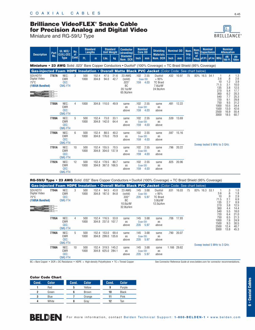
Conductor(stranding)DiameterNom. DCR
ShieldingMaterialsNom. DCR
No.of
Cond.
Nom.Imp.(Ω)
Nominal Core OD Nominal OD
Inch mm Inch mm
StandardUnit Weight
Standard Lengths
Lbs. kgFt. m
UL NEC/C(UL) CEC
Type MHz dB/100 Ft.
dB/100m
Nominal Attenuation
Nominal Capacitance
pF/mpF/Ft.
Nom.Vel.of
Prop.
Miniature • 23 AWG Solid .023″ Bare Copper Conductors • Duofoil® (100% Coverage) + TC Braid Shield (95% Coverage)
Gas-injected Foam HDPE Insulation • Overall Matte Black PVC Jacket (Color Code: See chart below)SDI/HDTV 7787A NEC: 3 500 152.4 47.5 21.6 23 AWG .102 2.55 Duofoil .432 10.97 75 83% 16.5 54.1Digital Video CMR 1000 304.8 94.0 42.7 (solid) Coax OD: + 95% 75°C CEC: .023″ .159 4.03 TC Braid(1855A Bundled) CMG FT4 BC 7.6Ω/M′
20.1Ω/M′ 24.9Ω/km. 65.9Ω/km
7788A NEC: 4 1000 304.8 110.0 49.9 same .102 2.55 same .481 12.22CMR as Coax OD: asCEC: above .159 4.03 above
CMG FT4
7789A NEC: 5 500 152.4 73.0 33.1 same .102 2.55 same .539 13.69CMR 1000 304.8 142.0 64.4 as Coax OD: asCEC: above .159 4.03 above
CMG FT4
7790A NEC: 6 500 152.4 88.5 40.2 same .102 2.55 same .597 15.16CMR 1000 304.8 176.0 79.9 as Coax OD: asCEC: above .159 4.03 above
CMG FT4
7791A NEC: 10 500 152.4 155.5 70.5 same .102 2.55 same .796 20.22CMR 1000 304.8 304.0 137.9 as Coax OD: asCEC: above .159 4.03 above
CMG FT4
7792A NEC: 12 500 152.4 178.5 80.7 same .102 2.55 same .825 20.96CMR 1000 304.8 367.0 166.5 as Coax OD: asCEC: above .159 4.03 above
CMG FT4
RG-59/U Type • 23 AWG Solid .032″ Bare Copper Conductors • Duofoil (100% Coverage) + TC Braid Shield (95% Coverage)
Gas-injected Foam HDPE Insulation • Overall Matte Black PVC Jacket (Color Code: See chart below)SDI/HDTV 7794A NEC: 3 500 152.4 94.5 43.0 23 AWG .145 3.68 Duofoil .631 16.03 75 83% 16.3 53.1Digital Video CMR 1000 304.8 187.0 84.8 (solid) Coax OD: + 95%75°C CEC: .032″ .235 5.97 TC Braid(1505A Bundled) CMG FT4 BC 3.8Ω/M′
10.0Ω/M′ 12.5Ω/km32.8Ω/km
7795A NEC: 4 500 152.4 116.5 53.0 same .145 3.68 same .706 17.93CMR 1000 304.8 237.0 107.7 as Coax OD: asCEC: above .235 5.97 above
CMG FT4
7796A NEC: 5 500 152.4 153.0 69.4 same .145 3.68 same .790 20.07CMR 1000 304.8 299.0 135.6 as Coax OD: asCEC: above .235 5.97 above
CMG FT4
7798A NEC: 10 500 152.4 319.5 145.2 same .145 3.68 same 1.166 29.62CMR 1000 304.8 625.0 284.1 as Coax OD: asCEC: above .235 5.97 above
CMG FT4BC = Bare Copper • DCR = DC Resistance • HDPE = High-density Polyethylene • TC = Tinned Copper See Connector Reference Guide at www.belden.com for connector recommendations.
C O A X I A L C A B L E S 6.45
Brilliance VideoFLEX® Snake Cablefor Precision Analog and Digital VideoMiniature and RG-59/U Type
6 •
Coax
ial C
able
s
F o r m o r e i n f o r m a t i o n , c o n t a c t B e l d e n Te c h n i c a l S u p p o r t : 1 - 8 0 0 - B E L D E N - 1 • w w w . b e l d e n . c o m
PartNo. dB/
100m
Description
Color Code Chart
Cond. Color1 Red
2 Green
3 Blue
4 White
Cond. Color5 Yellow
6 Brown
7 Orange
8 Gray
Cond. Color9 Purple
10 Black
11 Pink
12 Tan
1 .4 1.33.6 .8 2.610 1.2 3.9
71.5 3.1 10.0135 3.8 12.5270 5.4 17.7360 6.2 20.3540 7.7 25.3720 9.1 29.8750 9.5 31.2
1000 10.5 34.41500 13.0 42.62500 16.9 55.43000 18.5 60.7
1 .3 1.03.6 .6 1.810 .9 2.9
71.5 2.1 6.9135 2.7 8.9270 3.8 12.5360 4.4 14.4540 5.5 18.0720 6.4 21.0750 6.5 21.3
1000 7.6 24.91500 9.3 30.52500 12.4 40.73000 13.8 45.3
Sweep tested 5 MHz to 3 GHz.
Sweep tested 5 MHz to 3 GHz.
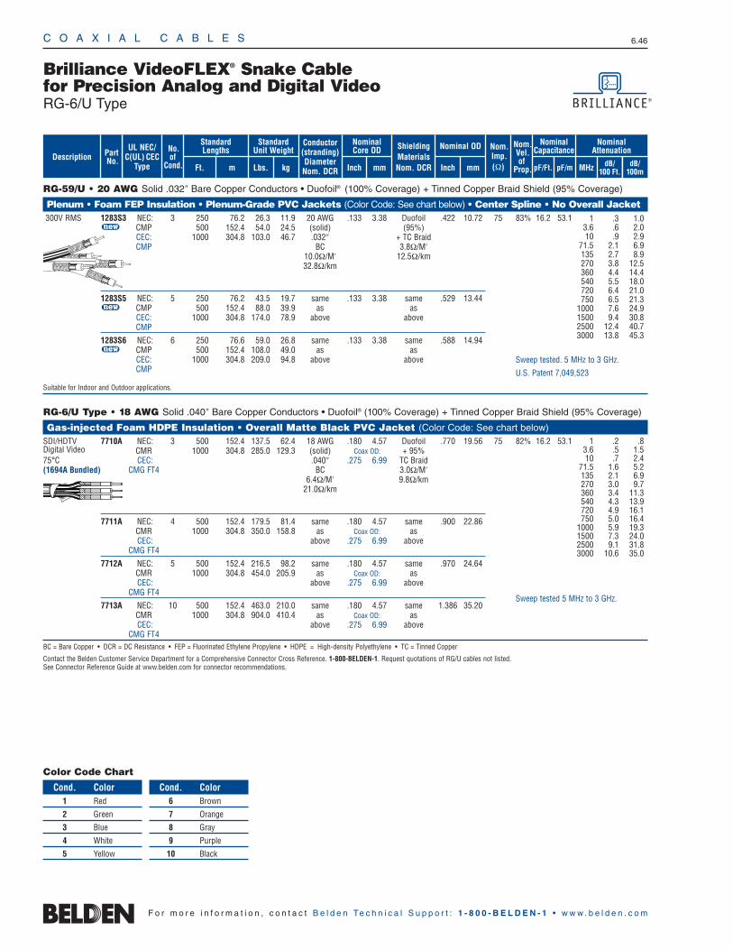
C O A X I A L C A B L E S 6.46
F o r m o r e i n f o r m a t i o n , c o n t a c t B e l d e n Te c h n i c a l S u p p o r t : 1 - 8 0 0 - B E L D E N - 1 • w w w . b e l d e n . c o m
RG-59/U • 20 AWG Solid .032″ Bare Copper Conductors • Duofoil® (100% Coverage) + Tinned Copper Braid Shield (95% Coverage)
Plenum • Foam FEP Insulation • Plenum-Grade PVC Jackets (Color Code: See chart below) • Center Spline • No Overall Jacket300V RMS 1283S3 NEC: 3 250 76.2 26.3 11.9 20 AWG .133 3.38 Duofoil .422 10.72 75 83% 16.2 53.1
u CMP 500 152.4 54.0 24.5 (solid) (95%)CEC: 1000 304.8 103.0 46.7 .032″ + TC BraidCMP BC 3.8Ω/M′
10.0Ω/M′ 12.5Ω/km32.8Ω/km
1283S5 NEC: 5 250 76.2 43.5 19.7 same .133 3.38 same .529 13.44u CMP 500 152.4 88.0 39.9 as as
CEC: 1000 304.8 174.0 78.9 above aboveCMP
1283S6 NEC: 6 250 76.6 59.0 26.8 same .133 3.38 same .588 14.94u CMP 500 152.4 108.0 49.0 as as
CEC: 1000 304.8 209.0 94.8 above aboveCMP
Suitable for Indoor and Outdoor applications.
RG-6/U Type • 18 AWG Solid .040″ Bare Copper Conductors • Duofoil® (100% Coverage) + Tinned Copper Braid Shield (95% Coverage)
Gas-injected Foam HDPE Insulation • Overall Matte Black PVC Jacket (Color Code: See chart below)SDI/HDTV 7710A NEC: 3 500 152.4 137.5 62.4 18 AWG .180 4.57 Duofoil .770 19.56 75 82% 16.2 53.1Digital Video CMR 1000 304.8 285.0 129.3 (solid) Coax OD: + 95%75°C CEC: .040″ .275 6.99 TC Braid(1694A Bundled) CMG FT4 BC 3.0Ω/M′
6.4Ω/M′ 9.8Ω/km21.0Ω/km
7711A NEC: 4 500 152.4 179.5 81.4 same .180 4.57 same .900 22.86CMR 1000 304.8 350.0 158.8 as Coax OD: asCEC: above .275 6.99 above
CMG FT4
7712A NEC: 5 500 152.4 216.5 98.2 same .180 4.57 same .970 24.64CMR 1000 304.8 454.0 205.9 as Coax OD: asCEC: above .275 6.99 above
CMG FT4
7713A NEC: 10 500 152.4 463.0 210.0 same .180 4.57 same 1.386 35.20CMR 1000 304.8 904.0 410.4 as Coax OD: asCEC: above .275 6.99 above
CMG FT4BC = Bare Copper • DCR = DC Resistance • FEP = Fluorinated Ethylene Propylene • HDPE = High-density Polyethylene • TC = Tinned Copper
Contact the Belden Customer Service Department for a Comprehensive Connector Cross Reference. 1-800-BELDEN-1. Request quotations of RG/U cables not listed.See Connector Reference Guide at www.belden.com for connector recommendations.
Brilliance VideoFLEX® Snake Cable for Precision Analog and Digital VideoRG-6/U Type
Color Code Chart
Cond. Color1 Red
2 Green
3 Blue
4 White
5 Yellow
Cond. Color6 Brown
7 Orange
8 Gray
9 Purple
10 Black
1 .2 .83.6 .5 1.510 .7 2.4
71.5 1.6 5.2135 2.1 6.9270 3.0 9.7360 3.4 11.3540 4.3 13.9720 4.9 16.1750 5.0 16.4
1000 5.9 19.31500 7.3 24.02500 9.1 31.83000 10.6 35.0
Sweep tested 5 MHz to 3 GHz.
Conductor(stranding)DiameterNom. DCR
ShieldingMaterialsNom. DCR
No.of
Cond.
Nom.Imp.(Ω)
Nominal Core OD Nominal OD
Inch mm Inch mm
StandardUnit Weight
Standard Lengths
Lbs. kgFt. m
UL NEC/C(UL) CEC
Type MHz dB/100 Ft.
dB/100m
Nominal Attenuation
Nominal Capacitance
pF/mpF/Ft.
Nom.Vel.of
Prop.
PartNo. dB/
100m
Description
1 .3 1.0 3.6 .6 2.0 10 .9 2.9
71.5 2.1 6.9135 2.7 8.9 270 3.8 12.5 360 4.4 14.4 540 5.5 18.0 720 6.4 21.0 750 6.5 21.3
1000 7.6 24.9 1500 9.4 30.8 2500 12.4 40.7 3000 13.8 45.3
Sweep tested. 5 MHz to 3 GHz.
U.S. Patent 7,049,523
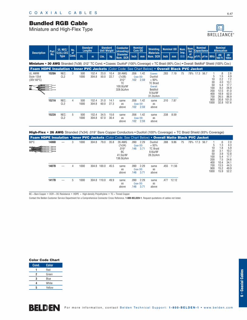
C O A X I A L C A B L E S 6.47
Bundled RGB CableMiniature and High-Flex Type
Miniature • 30 AWG Stranded (7x38) .012″ TC Cond. • Coaxes: Duofoil® (100% Coverage) + TC Braid (90% Cov.) • Overall: Beldfoil® Shield (100% Cov.)
Foam HDPE Insulation • Inner PVC Jackets (Color Code: See Chart Below) • Overall Black PVC Jacket UL AWM 1520A NEC: 3 500 152.4 23.0 10.4 30 AWG .056 1.42 Coaxes: .283 7.19 75 78% 17.3 56.7Style 1354 CL2 1000 304.8 50.0 22.7 (7x38) Coax OD: Duofoil(30V 60°C) .012″ .102 2.59 + 90%
TC TC Braid100.0Ω/M′ Overall:328.0Ω/km Beldfoil
9.5Ω/M′31.2Ω/km
1521A NEC: 4 500 152.4 31.0 14.1 same .056 1.42 same .310 7.87CL2 1000 304.8 60.0 27.3 as Coax OD: as
above .102 2.59 above
1522A NEC: 5 500 152.4 34.5 15.6 same .056 1.42 same .338 8.59CL2 1000 304.8 67.0 30.4 as Coax OD: as
above .102 2.59 above
High-Flex • 26 AWG Stranded (7x34) .019″ Bare Copper Conductors • Duofoil (100% Coverage) + TC Braid Shield (93% Coverage)
Foam HDPE Insulation • Inner PVC Jackets (Color Code: See Chart Below) • Overall Matte Black PVC Jacket60°C 1406B — 3 1000 304.8 79.0 35.8 26 AWG .090 2.29 Duofoil .388 9.86 75 78% 17.3 56.7
(7x34) Coax OD: + 93%.019″ .146 3.71 TC Braid
BC 8.6Ω/M′41.5Ω/M′ 28.2Ω/km
136.0Ω/km
1407B — 4 1000 304.8 100.0 45.5 same .090 2.29 same .455 11.56as Coax OD: as
above .146 3.71 above
1417B — 5 1000 304.8 110.0 49.9 same .090 2.29 same .477 12.12as Coax OD: as
above .146 3.71 above
BC = Bare Copper • DCR = DC Resistance • HDPE = High-density Polyethylene • TC = Tinned Copper
Contact the Belden Customer Service Department for a Comprehensive Connector Cross Reference. 1-800-BELDEN-1. Request quotations of cables not listed.
Color Code Chart
Cond. Color1 Red
2 Green
3 Blue
4 White
5 Yellow
6 •
Coax
ial C
able
s
F o r m o r e i n f o r m a t i o n , c o n t a c t B e l d e n Te c h n i c a l S u p p o r t : 1 - 8 0 0 - B E L D E N - 1 • w w w . b e l d e n . c o m
1 .8 2.65 1.5 4.9
10 2.2 7.230 4.0 13.150 5.4 17.7
100 8.2 26.9200 12.5 41.0400 18.9 62.0700 26.5 86.9900 30.8 101.0
1000 32.8 107.6
1 .6 2.05 1.3 4.3
10 1.8 5.930 3.1 10.250 3.9 12.8
100 5.4 17.7200 7.5 24.6400 10.4 34.1700 13.5 44.3900 15.2 49.9
1000 15.9 52.2
Conductor(stranding)DiameterNom. DCR
ShieldingMaterialsNom. DCR
No.of
Cond.
Nom.Imp.(Ω)
Nominal Core OD Nominal OD
Inch mm Inch mm
StandardUnit Weight
Standard Lengths
Lbs. kgFt. m
UL NEC/C(UL) CEC
Type MHz dB/100 Ft.
dB/100m
Nominal Attenuation
Nominal Capacitance
pF/mpF/Ft.
Nom.Vel.of
Prop.
PartNo. dB/
100m
Description
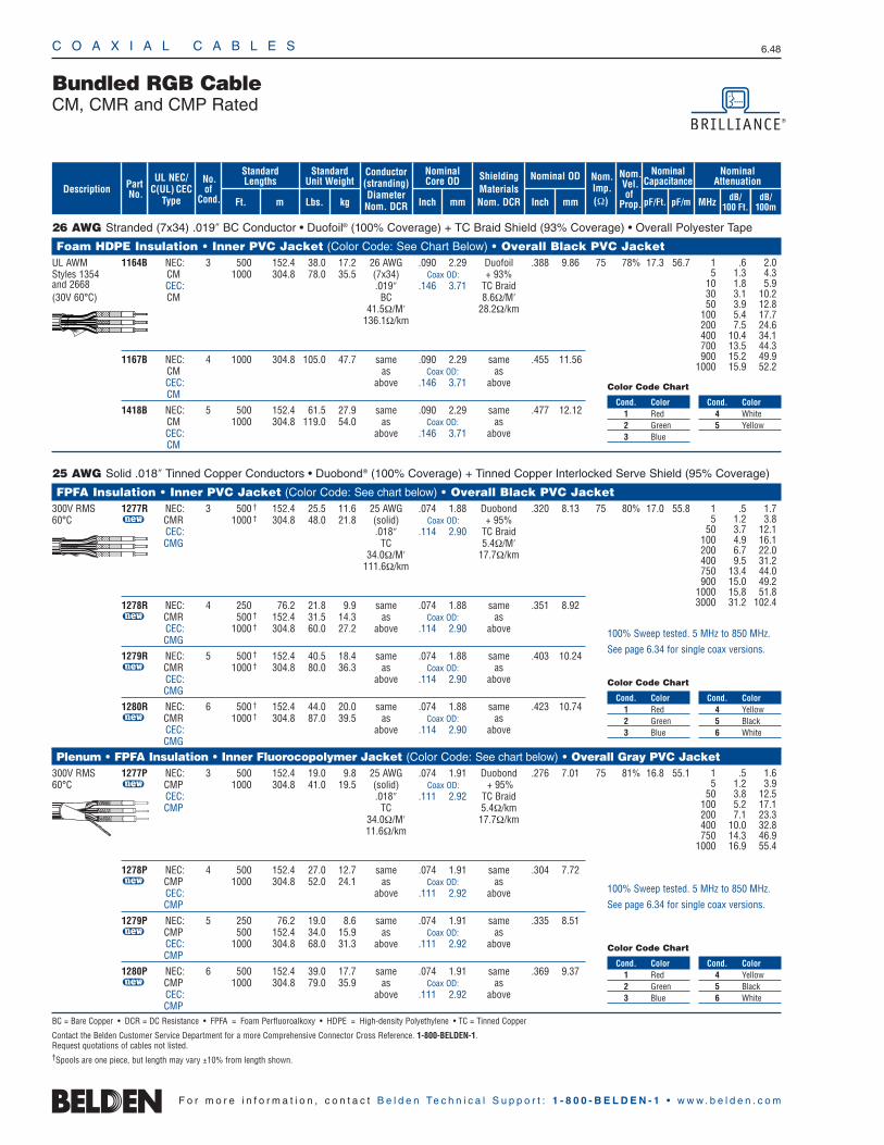
C O A X I A L C A B L E S 6.48
F o r m o r e i n f o r m a t i o n , c o n t a c t B e l d e n Te c h n i c a l S u p p o r t : 1 - 8 0 0 - B E L D E N - 1 • w w w . b e l d e n . c o m
26 AWG Stranded (7x34) .019″ BC Conductor • Duofoil® (100% Coverage) + TC Braid Shield (93% Coverage) • Overall Polyester Tape
Foam HDPE Insulation • Inner PVC Jacket (Color Code: See Chart Below) • Overall Black PVC Jacket UL AWM 1164B NEC: 3 500 152.4 38.0 17.2 26 AWG .090 2.29 Duofoil .388 9.86 75 78% 17.3 56.7Styles 1354 CM 1000 304.8 78.0 35.5 (7x34) Coax OD: + 93%and 2668 CEC: .019″ .146 3.71 TC Braid(30V 60°C) CM BC 8.6Ω/M′
41.5Ω/M′ 28.2Ω/km. 136.1Ω/km
1167B NEC: 4 1000 304.8 105.0 47.7 same .090 2.29 same .455 11.56CM as Coax OD: asCEC: above .146 3.71 aboveCM
1418B NEC: 5 500 152.4 61.5 27.9 same .090 2.29 same .477 12.12CM 1000 304.8 119.0 54.0 as Coax OD: asCEC: above .146 3.71 aboveCM
25 AWG Solid .018″ Tinned Copper Conductors • Duobond® (100% Coverage) + Tinned Copper Interlocked Serve Shield (95% Coverage)
FPFA Insulation • Inner PVC Jacket (Color Code: See chart below) • Overall Black PVC Jacket 300V RMS 1277R NEC: 3 500 † 152.4 25.5 11.6 25 AWG .074 1.88 Duobond .320 8.13 75 80% 17.0 55.860°C u CMR 1000 † 304.8 48.0 21.8 (solid) Coax OD: + 95%
CEC: .018″ .114 2.90 TC BraidCMG TC 5.4Ω/M′
34.0Ω/M′ 17.7Ω/km111.6Ω/km
1278R NEC: 4 250 76.2 21.8 9.9 same .074 1.88 same .351 8.92u CMR 500 † 152.4 31.5 14.3 as Coax OD: as
CEC: 1000 † 304.8 60.0 27.2 above .114 2.90 aboveCMG
1279R NEC: 5 500 † 152.4 40.5 18.4 same .074 1.88 same .403 10.24u CMR 1000 † 304.8 80.0 36.3 as Coax OD: as
CEC: above .114 2.90 aboveCMG
1280R NEC: 6 500 † 152.4 44.0 20.0 same .074 1.88 same .423 10.74u CMR 1000 † 304.8 87.0 39.5 as Coax OD: as
CEC: above .114 2.90 aboveCMG
Plenum • FPFA Insulation • Inner Fluorocopolymer Jacket (Color Code: See chart below) • Overall Gray PVC Jacket300V RMS 1277P NEC: 3 500 152.4 19.0 9.8 25 AWG .074 1.91 Duobond .276 7.01 75 81% 16.8 55.160°C u CMP 1000 304.8 41.0 19.5 (solid) Coax OD: + 95%
CEC: .018″ .111 2.92 TC BraidCMP TC 5.4Ω/km
34.0Ω/M′ 17.7Ω/km11.6Ω/km
1278P NEC: 4 500 152.4 27.0 12.7 same .074 1.91 same .304 7.72u CMP 1000 304.8 52.0 24.1 as Coax OD: as
CEC: above .111 2.92 aboveCMP
1279P NEC: 5 250 76.2 19.0 8.6 same .074 1.91 same .335 8.51u CMP 500 152.4 34.0 15.9 as Coax OD: as
CEC: 1000 304.8 68.0 31.3 above .111 2.92 aboveCMP
1280P NEC: 6 500 152.4 39.0 17.7 same .074 1.91 same .369 9.37u CMP 1000 304.8 79.0 35.9 as Coax OD: as
CEC: above .111 2.92 aboveCMP
BC = Bare Copper • DCR = DC Resistance • FPFA = Foam Perfluoroalkoxy • HDPE = High-density Polyethylene • TC = Tinned Copper
Contact the Belden Customer Service Department for a more Comprehensive Connector Cross Reference. 1-800-BELDEN-1.Request quotations of cables not listed.†Spools are one piece, but length may vary ±10% from length shown.
1 .6 2.05 1.3 4.3
10 1.8 5.930 3.1 10.250 3.9 12.8
100 5.4 17.7200 7.5 24.6400 10.4 34.1700 13.5 44.3900 15.2 49.9
1000 15.9 52.2
Bundled RGB CableCM, CMR and CMP Rated
Conductor(stranding)DiameterNom. DCR
ShieldingMaterialsNom. DCR
No.of
Cond.
Nom.Imp.(Ω)
Nominal Core OD Nominal OD
Inch mm Inch mm
StandardUnit Weight
Standard Lengths
Lbs. kgFt. m
UL NEC/C(UL) CEC
Type MHz dB/100 Ft.
dB/100m
Nominal Attenuation
Nominal Capacitance
pF/mpF/Ft.
Nom.Vel.of
Prop.
PartNo. dB/
100m
Description
1 .5 1.75 1.2 3.8
50 3.7 12.1100 4.9 16.1200 6.7 22.0400 9.5 31.2750 13.4 44.0900 15.0 49.2
1000 15.8 51.83000 31.2 102.4
1 .5 1.65 1.2 3.9
50 3.8 12.5100 5.2 17.1200 7.1 23.3400 10.0 32.8750 14.3 46.9
1000 16.9 55.4
100% Sweep tested. 5 MHz to 850 MHz.
See page 6.34 for single coax versions.
100% Sweep tested. 5 MHz to 850 MHz.
See page 6.34 for single coax versions.
Cond. Color1 Red2 Green3 Blue
Cond. Color4 Yellow5 Black6 White
Color Code Chart
Cond. Color1 Red2 Green3 Blue
Cond. Color4 Yellow5 Black6 White
Color Code Chart
Cond. Color1 Red2 Green3 Blue
Cond. Color4 White5 Yellow
Color Code Chart

C O A X I A L C A B L E S 6.49
6 •
Coax
ial C
able
s
F o r m o r e i n f o r m a t i o n , c o n t a c t B e l d e n Te c h n i c a l S u p p o r t : 1 - 8 0 0 - B E L D E N - 1 • w w w . b e l d e n . c o m
Bundled RGB CableBanana Peel® Unjacketed Bundles Mini Hi-Res Component VideoCMR and CMP Rated
Miniature • 25 AWG Solid .018″ TC Conductors • Duobond® (100% Coverage) + TC Interlocked Serve Shield (95% Coverage)
Gas-injected Foam HDPE Insulation • PVC Jackets (Color Code: See chart below) • Center Spline • No Overall Jacket1281S3 NEC: 3 500 † 152.4 17.0 7.7 25 AWG .074 1.88 Duobond Single: 75 80% 17.0 55.8u CMR 1000 † 304.8 31.0 14.1 (solid) (100%) .114 2.90
CEC: .018″ + TC Serve Overall:CMG TC (95%) .246 6.25
34.0Ω/M′ 5.4Ω/M′111.6Ω/km 17.7Ω/km
1281S4 NEC: 4 500 † 152.4 23.5 10.7 same .074 1.88 same Single:u CMR 1000 † 304.8 44.0 20.0 as as .114 2.90
CEC: above above Overall:CMG .275 6.99
1281S5 NEC: 5* 250 † 76.2 16.0 7.3 same .074 1.88 same Single:u CMR 500 † 152.4 28.5 12.9 as as .114 2.90
CEC: 1000 † 304.8 55.0 25.0 above above Overall:CMG .308 7.82
1281S6 NEC: 6* 500 † 152.4 33.5 15.2 same .074 1.88 same Single:u CMR 1000 † 304.8 68.0 30.8 as as .114 2.90
CEC: above above Overall:CMG FT4 .342 8.69
Plenum • FPFA • Flamarrest® Jackets (Color Code: See chart below) • Center Spline • No Overall Jacket1282S3 NEC: 3 500 152.4 18.5 8.4 25 AWG .075 1.91 Duobond Single: 75 81% 16.8 55.1u CMP 1000 304.8 34.0 15.4 (solid) (100%) .114 2.90
CEC: .018″ + TC Serve Overall:CMP TC (95%) .246 6.25
34.0Ω/M′ 5.4Ω/M′111.6Ω/km 17.7Ω/km
1282S4 NEC: 4 500 152.4 25.5 11.6 same .075 1.91 same Single:u CMP 1000 304.8 49.0 22.2 as as .114 2.90
CEC: above above Overall:CMP .275 6.99
1282S5 NEC: 5* 250 76.2 18.0 8.2 same .075 1.91 same Single:u CMP 500 152.4 33.0 15.0 as as .114 2.90
CEC: 1000 304.8 67.0 30.4 above above Overall:CMP .308 7.82
1282S6 NEC: 6* 500 152.4 39.5 17.9 same .075 1.91 same Single:u CMP 1000 304.8 80.0 36.3 as as .114 2.90
CEC: above above Overall:CMP .342 8.69
DCR = DC Resistance • FPFA = Foam Perfluoroalkoxy • HDPE = High-density Polyethylene • TC = Tinned Copper
Contact the Belden Customer Service Department for a more Comprehensive Connector Cross Reference. 1-800-BELDEN-1. Request quotations of cables not listed.†Spools are one piece, but length may vary ±10% from length shown.*Also available with all Black jackets.
1 .52 1.7 5 1.2 3.8
50 3.7 12.1 100 4.9 16.1 200 6.7 22.0 400 9.5 31.2 750 13.4 44.0 900 15.0 49.2
1000 15.8 51.8 3000 31.2 102.4
1 .50 1.6 5 1.2 3.9
50 3.8 12.1 100 5.2 17.1 200 7.1 23.1 400 10.0 32.9 750 14.3 47.0
1000 16.9 55.4 2250 25.5 83.6 3000 33.9 111.3
100% Sweep tested. 5 MHz to 850 MHz.Guaranteed Return Loss -20db max.
U.S. Patent 7,049,523
100% Sweep tested. 5 MHz to 850 MHz.Guaranteed Return Loss -20db max.
U.S. Patent 7,049,523
Conductor(stranding)DiameterNom. DCR
ShieldingMaterialsNom. DCR
No.of
Cond.
Nom.Imp.(Ω)
Nominal Core OD Nominal OD
Inch mm Inch mm
StandardUnit Weight
Standard Lengths
Lbs. kgFt. m
UL NEC/C(UL) CEC
Type MHz dB/100 Ft.
dB/100m
Nominal Attenuation
Nominal Capacitance
pF/mpF/Ft.
Nom.Vel.of
Prop.
PartNo. dB/
100m
Description
Color Code Chart:
Cond. Color1 Red
2 Green
3 Blue
Cond. Color4 Yellow
5 Black
6 White
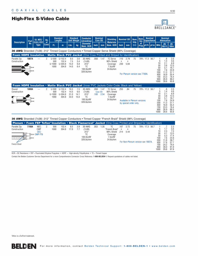
C O A X I A L C A B L E S 6.50
F o r m o r e i n f o r m a t i o n , c o n t a c t B e l d e n Te c h n i c a l S u p p o r t : 1 - 8 0 0 - B E L D E N - 1 • w w w . b e l d e n . c o m
30 AWG Stranded (7x38) .012″ Tinned Copper Conductors • Tinned Copper Serve Shield (90% Coverage)
Foam HDPE Insulation • Matte Black PVC Jacket (One Coax Printed and Striped for Identification)Parallel Zip 1807A — 2 U-500 U-152.4 8.0 3.6 30 AWG .058 1.47 TC Serve .110 2.79 75 78% 17.3 56.7Construction 500 152.4 7.5 3.4 (7x38) 90% Shield x x
U-1000 U-304.8 15.0 6.8 .012″ Coverage .230 5.841000 304.8 14.0 6.4 TC 7.5Ω/M′
100.0Ω/M′ 24.6Ω/km328.0Ω/km
Foam HDPE Insulation • Matte Black PVC Jacket (Inner PVC Jackets Color Code: Black and Yellow)Round 1808A — 2 U-500 U-152.4 16.5 7.5 30 AWG .058 1.47 TC Serve .255 .84 75 78% 17.3 56.7Construction 500 152.4 14.5 6.6 (7x38) Coax OD: 90% Shield
U-1000 U-304.8 31.0 14.1 .013″ .100 2.54 Coverage1000 304.8 33.0 15.0 TC 7.5Ω/M′
100.0Ω/M′ 24.6Ω/km328.0Ω/km
30 AWG Stranded (7x38) .012″ Tinned Copper Conductors • Tinned Copper “French Braid” Shield (98% Coverage)
Plenum • Foam FEP Teflon® Insulation • Black Flamarrest® Jacket (One Coax Printed and Striped for Identification)Parallel Zip 7700A NEC: 2 500 152.4 8.5 3.9 30 AWG .053 1.35 TC .107 2.72 75 78% 17.3 56.7Construction CMP 1000 304.8 17.0 7.7 (7x38) “French Braid” x x
CEC: .012″ 98% Shield .214 5.44CMP FT6 TC Coverage
100.0Ω/M′ 7.5Ω/M′328.0Ω/km 24.6Ω/km
DCR = DC Resistance • FEP = Fluorinated Ethylene Propylene • HDPE = High-density Polyethylene • TC = Tinned Copper
Contact the Belden Customer Service Department for a more Comprehensive Connector Cross Reference. 1-800-BELDEN-1. Request quotations of cables not listed.
Available in Plenum versions by special order only.
For Plenum version see 7700A.
For Non-Plenum version see 1807A.
High-Flex S-Video Cable
1 .6 2.05 1.4 4.6
10 2.1 6.930 3.8 12.550 5.1 16.7
100 7.6 24.9200 11.3 37.1400 16.9 55.4700 23.3 76.4900 26.9 88.2
1000 28.6 93.8
1 .6 2.05 1.4 4.6
10 2.1 6.930 3.8 12.550 5.1 16.7
100 7.6 24.9200 11.3 37.1400 16.9 55.4700 23.3 76.4900 26.9 88.3
1000 28.6 93.8
1 .7 2.35 1.7 5.6
10 2.3 7.530 4.1 13.550 5.3 17.4
100 7.6 24.9200 11.8 38.7400 17.6 57.7700 24.2 79.4900 28.0 91.9
1000 29.8 97.8
French Braid
Conductor(stranding)DiameterNom. DCR
ShieldingMaterialsNom. DCR
No.of
Cond.
Nom.Imp.(Ω)
Nominal Core OD Nominal OD
Inch mm Inch mm
StandardUnit Weight
Standard Lengths
Lbs. kgFt. m
UL NEC/C(UL) CEC
Type MHz dB/100 Ft.
dB/100m
Nominal Attenuation
Nominal Capacitance
pF/mpF/Ft.
Nom.Vel.of
Prop.
PartNo. dB/
100m
Description
Teflon is a DuPont trademark.
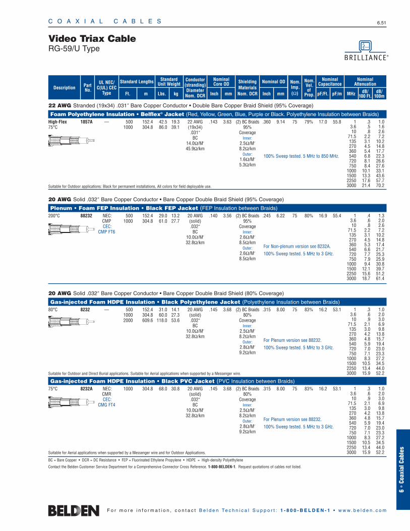
C O A X I A L C A B L E S 6.51
6 •
Coax
ial C
able
s
F o r m o r e i n f o r m a t i o n , c o n t a c t B e l d e n Te c h n i c a l S u p p o r t : 1 - 8 0 0 - B E L D E N - 1 • w w w . b e l d e n . c o m
22 AWG Stranded (19x34) .031″ Bare Copper Conductor • Double Bare Copper Braid Shield (95% Coverage)
Foam Polyethylene Insulation • Belflex® Jacket (Red, Yellow, Green, Blue, Purple or Black. Polyethylene Insulation between Braids)High-Flex 1857A — 500 152.4 42.5 19.3 22 AWG .143 3.63 (2) BC Braids .360 9.14 75 79% 17.0 55.875°C 1000 304.8 86.0 39.1 (19x34) 95%
.031″ CoverageBC Inner:
14.0Ω/M′ 2.5Ω/M′45.9Ω/km 8.2Ω/km
Outer:1.6Ω/M′5.3Ω/km
Suitable for Outdoor applications: Black for permanent installations, All colors for field deployable use.
20 AWG Solid .032″ Bare Copper Conductor • Bare Copper Double Braid Shield (95% Coverage)
Plenum • Foam FEP Insulation • Black FEP Jacket (FEP Insulation between Braids)200°C 88232 NEC: 500 152.4 29.0 13.2 20 AWG .140 3.56 (2) BC Braids .245 6.22 75 80% 16.9 55.4
CMP 1000 304.8 61.0 27.7 (solid) 95% CEC: .032″ Coverage
CMP FT6 BC Inner:10.0Ω/M′ 2.6Ω/M′32.8Ω/km 8.5Ω/km
Outer:2.6Ω/M′8.5Ω/km
20 AWG Solid .032″ Bare Copper Conductor • Bare Copper Double Braid Shield (80% Coverage)
Gas-injected Foam HDPE Insulation • Black Polyethylene Jacket (Polyethylene Insulation between Braids)80°C 8232 — 500 152.4 31.0 14.1 20 AWG .145 3.68 (2) BC Braids .315 8.00 75 83% 16.2 53.1
1000 304.8 60.0 27.3 (solid) 80%2000 609.6 118.0 53.6 .032″ Coverage
BC Inner:10.0Ω/M′ 2.5Ω/M′32.8Ω/km 8.2Ω/km
Outer:2.8Ω/M′9.2Ω/km
Suitable for Outdoor and Direct Burial applications. Suitable for Aerial applications when supported by a Messenger wire.
Gas-injected Foam HDPE Insulation • Black PVC Jacket (PVC Insulation between Braids)75°C 8232A NEC: 1000 304.8 68.0 30.8 20 AWG .145 3.68 (2) BC Braids .315 8.00 75 83% 16.2 53.1
CMR (solid) 80% CEC: .032″ Coverage
CMG FT4 BC Inner:10.0Ω/M′ 2.5Ω/M′32.8Ω/km 8.2Ω/km
Outer:2.8Ω/M′9.2Ω/km
Suitable for Aerial applications when supported by a Messenger wire and for Outdoor Applications.
BC = Bare Copper • DCR = DC Resistance • FEP = Fluorinated Ethylene Propylene • HDPE = High-density Polyethylene
Contact the Belden Customer Service Department for a Comprehensive Connector Cross Reference. 1-800-BELDEN-1. Request quotations of cables not listed.
Video Triax CableRG-59/U Type
1 .3 1.03.6 .5 1.610 .8 2.6
71.5 2.2 7.2135 3.1 10.2270 4.5 14.8360 5.4 17.7540 6.8 22.3720 8.1 26.6750 8.4 27.6
1000 10.1 33.11500 13.3 43.62250 17.6 57.73000 21.4 70.2
1 .3 1.03.6 .6 2.010 .9 3.0
71.5 2.1 6.9135 3.0 9.8270 4.2 13.8360 4.8 15.7540 5.9 19.4720 7.0 23.0750 7.1 23.3
1000 8.3 27.21500 10.5 34.52250 13.4 44.03000 15.9 52.2
1 .3 1.03.6 .6 2.010 .9 3.0
71.5 2.1 6.9135 3.0 9.8270 4.2 13.8360 4.8 15.7540 5.9 19.4720 7.0 23.0750 7.1 23.3
1000 8.3 27.21500 10.5 34.52250 13.4 44.03000 15.9 52.2
1 .4 1.33.6 .6 2.010 .8 2.6
71.5 2.2 7.2135 3.1 10.2270 4.5 14.8360 5.3 17.4540 6.6 21.7720 7.7 25.3750 7.9 25.9
1000 9.4 30.81500 12.1 39.72250 15.6 51.23000 18.7 61.4
For Plenum version see 88232.
100% Sweep tested. 5 MHz to 3 GHz.
For Plenum version see 88232.
100% Sweep tested. 5 MHz to 3 GHz.
100% Sweep tested. 5 MHz to 850 MHz.
For Non-plenum version see 8232A.
100% Sweep tested. 5 MHz to 3 GHz.
ShieldingMaterialsNom. DCR
Nom.Imp.(Ω)
Nominal Core OD Nominal OD
Inch mm Inch mm
Conductor(stranding)DiameterNom. DCR
StandardUnit WeightStandard Lengths
Lbs. kgFt. m
UL NEC/C(UL) CEC
Type
PartNo.
MHz dB/100 Ft.
dB/100m
Nominal Attenuation
Nominal Capacitance
pF/mpF/Ft.
Nom.Vel.of
Prop.Description
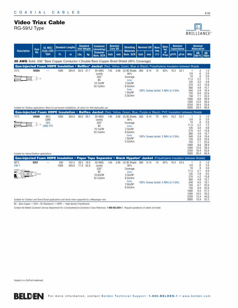
20 AWG Solid .032″ Bare Copper Conductor • Double Bare Copper Braid Shield (95% Coverage)
Gas-injected Foam HDPE Insulation • Belflex® Jacket (Red, Yellow, Green, Blue or Black); Polyethylene Insulation between Braids
75°C 1856A — 1000 304.8 83.0 37.7 20 AWG .145 3.68 (2) BC Braids .360 9.14 75 83% 16.2 53.1(solid) 95% .032″ Coverage
BC Inner:10.1Ω/M′ 2.5Ω/M′33.1Ω/km 8.2Ω/km
Outer:1.6Ω/M′5.3Ω/km
Suitable for Outdoor applications: Black for permanent installations, all colors for field deployable use.
Gas-injected Foam HDPE Insulation • Belflex Jacket (Red, Yellow, Green, Blue, Purple or Black); PVC Insulation between Braids
75°C 1856B NEC: 1000 304.8 86.0 39.1 20 AWG .145 3.68 (2) BC Braids .360 9.14 75 83% 16.2 53.1CMR (solid) 95% CEC: .032″ Coverage
CMG FT4 BC Inner:10.1Ω/M′ 2.5Ω/M′33.1Ω/km 8.2Ω/km
Outer:1.6Ω/M′5.2Ω/km
Suitable for Indoor/Outdoor applications.
Gas-injected Foam HDPE Insulation • Paper Tape Separator • Black Hypalon® Jacket (Polyethylene Insulation between Braids)
80°C 9267 — 500 152.4 39.5 18.0 20 AWG .145 3.68 (2) BC Braids .360 9.14 75 82% 16.3 53.5VW-1 1000 304.8 77.0 35.0 (solid) 95%
.032″ CoverageBC Inner:
10.0Ω/M′ 2.5Ω/M′33.1Ω/km 8.2Ω/km
Outer:2.6Ω/M′8.5Ω/km
Suitable for Outdoor and Direct Burial applications and Aerial when supported by a Messenger wire.
BC = Bare Copper • DCR = DC Resistance • HDPE = High-density Polyethylene
Contact the Belden Customer Service Department for a Comprehensive Connector Cross Reference. 1-800-BELDEN-1. Request quotations of cables not listed.
C O A X I A L C A B L E S 6.52
F o r m o r e i n f o r m a t i o n , c o n t a c t B e l d e n Te c h n i c a l S u p p o r t : 1 - 8 0 0 - B E L D E N - 1 • w w w . b e l d e n . c o m
Video Triax CableRG-59/U Type
1 .3 1.03.6 .6 2.010 .8 2.6
71.5 2.2 7.2135 3.0 9.8270 4.2 13.8360 4.8 15.7540 5.9 19.4720 6.9 22.6750 7.1 23.3
1000 8.8 28.91500 12.0 39.42250 16.4 53.83000 20.4 66.9
1 .3 1.03.6 .6 2.010 .8 2.6
71.5 2.2 7.2135 3.0 9.8270 4.2 13.8360 4.8 15.7540 5.9 19.4720 6.9 22.6750 7.1 23.3
1000 8.8 28.91500 12.0 39.42250 16.4 53.83000 20.4 66.9
1 .3 1.03.6 .6 2.010 .9 3.0
71.5 2.1 6.9135 2.9 9.5270 4.2 13.8360 4.8 15.7540 6.0 19.7720 6.7 22.0750 6.9 22.6
1000 8.3 27.21500 10.5 34.52250 13.4 44.03000 15.9 52.2
Hypalon is a DuPont trademark.
100% Sweep tested. 5 MHz to 3 GHz.
100% Sweep tested. 5 MHz to 3 GHz.
100% Sweep tested. 5 MHz to 3 GHz.
ShieldingMaterialsNom. DCR
Nom.Imp.(Ω)
Nominal Core OD Nominal OD
Inch mm Inch mm
Conductor(stranding)DiameterNom. DCR
StandardUnit WeightStandard Lengths
Lbs. kgFt. m
UL NEC/C(UL) CEC
Type
PartNo.
MHz dB/100 Ft.
dB/100m
Nominal Attenuation
Nominal Capacitance
pF/mpF/Ft.
Nom.Vel.of
Prop.Description
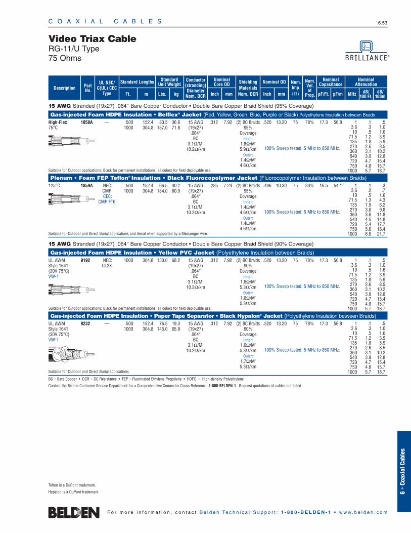
C O A X I A L C A B L E S 6.53
6 •
Coax
ial C
able
s
F o r m o r e i n f o r m a t i o n , c o n t a c t B e l d e n Te c h n i c a l S u p p o r t : 1 - 8 0 0 - B E L D E N - 1 • w w w . b e l d e n . c o m
15 AWG Stranded (19x27) .064″ Bare Copper Conductor • Double Bare Copper Braid Shield (95% Coverage)
Gas-injected Foam HDPE Insulation • Belflex® Jacket (Red, Yellow, Green, Blue, Purple or Black) Polyethylene Insulation between Braids
High-Flex 1858A — 500 152.4 80.5 36.8 15 AWG .312 7.92 (2) BC Braids .520 13.20 75 78% 17.3 56.875°C 1000 304.8 157.0 71.8 (19x27) 95%
.064″ CoverageBC Inner:
3.1Ω/M′ 1.8Ω/M′10.2Ω/km 5.9Ω/km
Outer:1.4Ω/M′4.6Ω/km
Suitable for Outdoor applications: Black for permanent installations, all colors for field deployable use.
Plenum • Foam FEP Teflon® Insulation • Black Fluorocopolymer Jacket (Fluorocopolymer Insulation between Braids)125°C 1859A NEC: 500 152.4 66.5 30.2 15 AWG .285 7.24 (2) BC Braids .406 10.30 75 80% 16.5 54.1
CMP 1000 304.8 134.0 60.9 (19x27) 95% CEC: .064″ Coverage
CMP FT6 BC Inner:3.1Ω/M′ 1.4Ω/M′
10.2Ω/km 4.6Ω/kmOuter:
1.4Ω/M′4.6Ω/km
Suitable for Outdoor and Direct Burial applications and Aerial when supported by a Messenger wire.
15 AWG Stranded (19x27) .064″ Bare Copper Conductor • Double Bare Copper Braid Shield (90% Coverage)
Gas-injected Foam HDPE Insulation • Yellow PVC Jacket (Polyethylene Insulation between Braids)UL AWM 9192 NEC: 1000 304.8 150.0 68.2 15 AWG .312 7.92 (2) BC Braids .520 13.20 75 78% 17.3 56.8Style 1641 CL2X (19x27) 90% (30V 75°C) .064″ CoverageVW-1 BC Inner:
3.1Ω/M′ 1.6Ω/M′10.2Ω/km 5.3Ω/km
Outer:1.6Ω/M′5.3Ω/km
Suitable for Outdoor applications: Black for permanent installations, all colors for field deployable use.
Gas-injected Foam HDPE Insulation • Paper Tape Separator • Black Hypalon® Jacket (Polyethylene Insulation between Braids)UL AWM 9232 — 500 152.4 76.5 19.3 15 AWG .312 7.92 (2) BC Braids .520 13.20 75 78% 17.3 56.8Style 1641 1000 304.8 145.0 65.9 (19x27) 90% (30V 75°C) .064″ CoverageVW-1 BC Inner:
3.1Ω/M′ 1.6Ω/M′10.2Ω/km 5.3Ω/km
Outer:1.7Ω/M′5.3Ω/km
Suitable for Outdoor and Direct Burial applications.
BC = Bare Copper • DCR = DC Resistance • FEP = Fluorinated Ethylene Propylene • HDPE = High-density Polyethylene
Contact the Belden Customer Service Department for a Comprehensive Connector Cross Reference. 1-800-BELDEN-1. Request quotations of cables not listed.
Video Triax CableRG-11/U Type75 Ohms
1 .1 .53.6 .3 1.010 .5 1.6
71.5 1.2 3.9135 1.8 5.9270 2.6 8.5360 3.1 10.2540 3.9 12.8720 4.7 15.4750 4.8 15.7
1000 5.7 18.7
1 .1 .53.6 .3 1.010 .5 1.6
71.5 1.2 3.9135 1.8 5.9270 2.6 8.5360 3.1 10.2540 3.9 12.8720 4.7 15.4750 4.8 15.7
1000 5.7 18.7
1 .1 .53.6 .3 1.010 .5 1.6
71.5 1.2 3.9135 1.8 5.9270 2.6 8.5360 3.1 10.2540 3.9 12.8720 4.7 15.4750 4.8 15.7
1000 5.7 18.7
1 .1 .33.6 .2 .710 .5 1.6
71.5 1.3 4.3135 1.9 6.2270 3.0 9.8360 3.6 11.8540 4.5 14.8720 5.4 17.7750 5.6 18.4
1000 6.6 21.7
Teflon is a DuPont trademark.
Hypalon is a DuPont trademark.
100% Sweep tested. 5 MHz to 850 MHz.
100% Sweep tested. 5 MHz to 850 MHz.
100% Sweep tested. 5 MHz to 850 MHz.
100% Sweep tested. 5 MHz to 850 MHz.
ShieldingMaterialsNom. DCR
Nom.Imp.(Ω)
Nominal Core OD Nominal OD
Inch mm Inch mm
Conductor(stranding)DiameterNom. DCR
StandardUnit WeightStandard Lengths
Lbs. kgFt. m
UL NEC/C(UL) CEC
Type
PartNo.
MHz dB/100 Ft.
dB/100m
Nominal Attenuation
Nominal Capacitance
pF/mpF/Ft.
Nom.Vel.of
Prop.Description
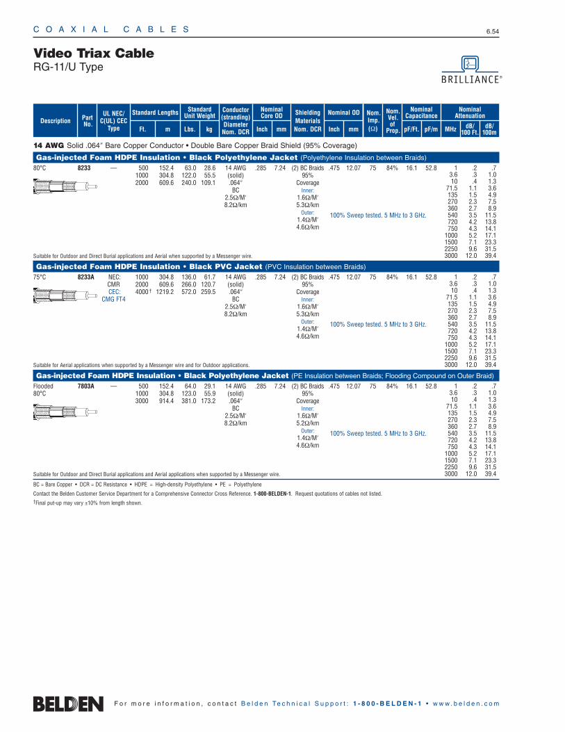
C O A X I A L C A B L E S 6.54
F o r m o r e i n f o r m a t i o n , c o n t a c t B e l d e n Te c h n i c a l S u p p o r t : 1 - 8 0 0 - B E L D E N - 1 • w w w . b e l d e n . c o m
14 AWG Solid .064″ Bare Copper Conductor • Double Bare Copper Braid Shield (95% Coverage)
Gas-injected Foam HDPE Insulation • Black Polyethylene Jacket (Polyethylene Insulation between Braids)
80°C 8233 — 500 152.4 63.0 28.6 14 AWG .285 7.24 (2) BC Braids .475 12.07 75 84% 16.1 52.81000 304.8 122.0 55.5 (solid) 95% 2000 609.6 240.0 109.1 .064″ Coverage
BC Inner:2.5Ω/M′ 1.6Ω/M′8.2Ω/km 5.3Ω/km
Outer:1.4Ω/M′4.6Ω/km
Suitable for Outdoor and Direct Burial applications and Aerial when supported by a Messenger wire.
Gas-injected Foam HDPE Insulation • Black PVC Jacket (PVC Insulation between Braids)
75°C 8233A NEC: 1000 304.8 136.0 61.7 14 AWG .285 7.24 (2) BC Braids .475 12.07 75 84% 16.1 52.8CMR 2000 609.6 266.0 120.7 (solid) 95% CEC: 4000 † 1219.2 572.0 259.5 .064″ Coverage
CMG FT4 BC Inner:2.5Ω/M′ 1.6Ω/M′8.2Ω/km 5.3Ω/km
Outer:1.4Ω/M′4.6Ω/km
Suitable for Aerial applications when supported by a Messenger wire and for Outdoor applications.
Gas-injected Foam HDPE Insulation • Black Polyethylene Jacket (PE Insulation between Braids; Flooding Compound on Outer Braid)
Flooded 7803A — 500 152.4 64.0 29.1 14 AWG .285 7.24 (2) BC Braids .475 12.07 75 84% 16.1 52.880°C 1000 304.8 123.0 55.9 (solid) 95%
3000 914.4 381.0 173.2 .064″ CoverageBC Inner:
2.5Ω/M′ 1.6Ω/M′8.2Ω/km 5.2Ω/km
Outer:1.4Ω/M′4.6Ω/km
Suitable for Outdoor and Direct Burial applications and Aerial applications when supported by a Messenger wire.
BC = Bare Copper • DCR = DC Resistance • HDPE = High-density Polyethylene • PE = Polyethylene
Contact the Belden Customer Service Department for a Comprehensive Connector Cross Reference. 1-800-BELDEN-1. Request quotations of cables not listed.†Final put-up may vary ±10% from length shown.
Video Triax CableRG-11/U Type
1 .2 .73.6 .3 1.010 .4 1.3
71.5 1.1 3.6135 1.5 4.9270 2.3 7.5360 2.7 8.9540 3.5 11.5720 4.2 13.8750 4.3 14.1
1000 5.2 17.11500 7.1 23.32250 9.6 31.53000 12.0 39.4
1 .2 .73.6 .3 1.010 .4 1.3
71.5 1.1 3.6135 1.5 4.9270 2.3 7.5360 2.7 8.9540 3.5 11.5720 4.2 13.8750 4.3 14.1
1000 5.2 17.11500 7.1 23.32250 9.6 31.53000 12.0 39.4
1 .2 .73.6 .3 1.010 .4 1.3
71.5 1.1 3.6135 1.5 4.9270 2.3 7.5360 2.7 8.9540 3.5 11.5720 4.2 13.8750 4.3 14.1
1000 5.2 17.11500 7.1 23.32250 9.6 31.53000 12.0 39.4
100% Sweep tested. 5 MHz to 3 GHz.
100% Sweep tested. 5 MHz to 3 GHz.
100% Sweep tested. 5 MHz to 3 GHz.
ShieldingMaterialsNom. DCR
Nom.Imp.(Ω)
Nominal Core OD Nominal OD
Inch mm Inch mm
Conductor(stranding)DiameterNom. DCR
StandardUnit WeightStandard Lengths
Lbs. kgFt. m
UL NEC/C(UL) CEC
Type
PartNo.
MHz dB/100 Ft.
dB/100m
Nominal Attenuation
Nominal Capacitance
pF/mpF/Ft.
Nom.Vel.of
Prop.Description
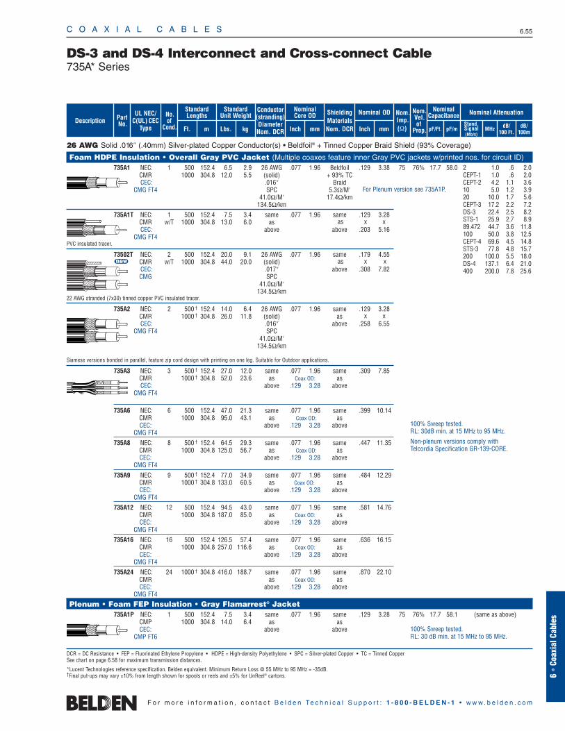
C O A X I A L C A B L E S 6.55
6 •
Coax
ial C
able
s
F o r m o r e i n f o r m a t i o n , c o n t a c t B e l d e n Te c h n i c a l S u p p o r t : 1 - 8 0 0 - B E L D E N - 1 • w w w . b e l d e n . c o m
26 AWG Solid .016″ (.40mm) Silver-plated Copper Conductor(s) • Beldfoil® + Tinned Copper Braid Shield (93% Coverage)
Foam HDPE Insulation • Overall Gray PVC Jacket (Multiple coaxes feature inner Gray PVC jackets w/printed nos. for circuit ID)735A1 NEC: 1 500 152.4 6.5 2.9 26 AWG .077 1.96 Beldfoil .129 3.38 75 76% 17.7 58.0
CMR 1000 304.8 12.0 5.5 (solid) + 93% TCCEC: .016″ Braid
CMG FT4 SPC 5.3Ω/M′41.0Ω/M′ 17.4Ω/km
134.5Ω/km
735A1T NEC: 1 500 152.4 7.5 3.4 same .077 1.96 same .129 3.28CMR w/T 1000 304.8 13.0 6.0 as as x xCEC: above above .203 5.16
CMG FT4PVC insulated tracer.
73502T NEC: 2 500 152.4 20.0 9.1 26 AWG .077 1.96 same .179 4.55u CMR w/T 1000 304.8 44.0 20.0 (solid) as x x
CEC: .017″ above .308 7.82CMG SPC
41.0Ω/M′134.5Ω/km
22 AWG stranded (7x30) tinned copper PVC insulated tracer.
735A2 NEC: 2 500 † 152.4 14.0 6.4 26 AWG .077 1.96 same .129 3.28CMR 1000 † 304.8 26.0 11.8 (solid) as x xCEC: .016″ above .258 6.55
CMG FT4 SPC41.0Ω/M′
134.5Ω/km
Siamese versions bonded in parallel, feature zip cord design with printing on one leg. Suitable for Outdoor applications.
735A3 NEC: 3 500 † 152.4 27.0 12.0 same .077 1.96 same .309 7.85CMR 1000 † 304.8 52.0 23.6 as Coax OD: asCEC: above .129 3.28 above
CMG FT4
735A6 NEC: 6 500 152.4 47.0 21.3 same .077 1.96 same .399 10.14CMR 1000 304.8 95.0 43.1 as Coax OD: asCEC: above .129 3.28 above
CMG FT4
735A8 NEC: 8 500 † 152.4 64.5 29.3 same .077 1.96 same .447 11.35CMR 1000 304.8 125.0 56.7 as Coax OD: asCEC: above .129 3.28 above
CMG FT4
735A9 NEC: 9 500 † 152.4 77.0 34.9 same .077 1.96 same .484 12.29CMR 1000 † 304.8 133.0 60.5 as Coax OD: asCEC: above .129 3.28 above
CMG FT4
735A12 NEC: 12 500 152.4 94.5 43.0 same .077 1.96 same .581 14.76CMR 1000 304.8 187.0 85.0 as Coax OD: asCEC: above .129 3.28 above
CMG FT4
735A16 NEC: 16 500 152.4 126.5 57.4 same .077 1.96 same .636 16.15CMR 1000 304.8 257.0 116.6 as Coax OD: asCEC: above .129 3.28 above
CMG FT4
735A24 NEC: 24 1000 † 304.8 416.0 188.7 same .077 1.96 same .870 22.10CMR as Coax OD: asCEC: above .129 3.28 above
CMG FT4
Plenum • Foam FEP Insulation • Gray Flamarrest® Jacket 735A1P NEC: 1 500 152.4 7.5 3.4 same .077 1.96 same .129 3.28 75 76% 17.7 58.1
CMP 1000 304.8 14.0 6.4 as asCEC: above above
CMP FT6
DCR = DC Resistance • FEP = Fluorinated Ethylene Propylene • HDPE = High-density Polyethylene • SPC = Silver-plated Copper • TC = Tinned CopperSee chart on page 6.58 for maximum transmission distances.
*Lucent Technologies reference specification. Belden equivalent. Minimum Return Loss @ 55 MHz to 95 MHz = -35dB.†Final put-ups may vary ±10% from length shown for spools or reels and ±5% for UnReel® cartons.
DS-3 and DS-4 Interconnect and Cross-connect Cable735A* Series
2 1.0 .6 2.0CEPT-1 1.0 .6 2.0CEPT-2 4.2 1.1 3.610 5.0 1.2 3.920 10.0 1.7 5.6CEPT-3 17.2 2.2 7.2DS-3 22.4 2.5 8.2STS-1 25.9 2.7 8.989.472 44.7 3.6 11.8100 50.0 3.8 12.5CEPT-4 69.6 4.5 14.8STS-3 77.8 4.8 15.7200 100.0 5.5 18.0DS-4 137.1 6.4 21.0400 200.0 7.8 25.6
(same as above)
100% Sweep tested.RL: 30dB min. at 15 MHz to 95 MHz.
Non-plenum versions comply withTelcordia Specification GR-139-CORE.
100% Sweep tested.RL: 30 dB min. at 15 MHz to 95 MHz.
For Plenum version see 735A1P.
Conductor(stranding)DiameterNom. DCR
Nominal Core OD
Inch mm
Nominal OD
Inch mm
ShieldingMaterialsNom. DCR
StandardUnit Weight
kg
No.of
Cond.
Nom.Imp.(Ω)
Standard Lengths
Lbs.Ft. m
UL NEC/C(UL) CEC
Type
PartNo. Stand.
Signal(Mb/s)
MHz dB/100 Ft.
dB/100m
Nominal AttenuationNominalCapacitance
pF/mpF/Ft.
Nom.Vel.of
Prop.Description
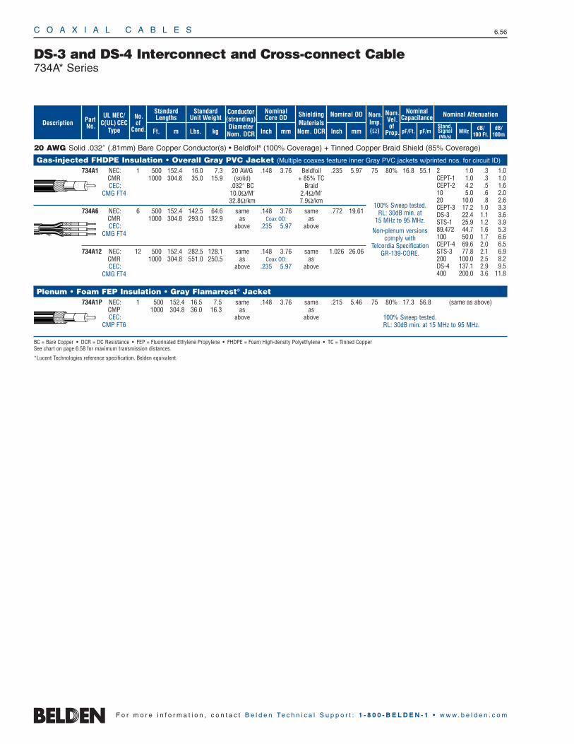
Stand.Signal(Mb/s)
MHz dB/100 Ft.
dB/100m
20 AWG Solid .032″ (.81mm) Bare Copper Conductor(s) • Beldfoil® (100% Coverage) + Tinned Copper Braid Shield (85% Coverage)
Gas-injected FHDPE Insulation • Overall Gray PVC Jacket (Multiple coaxes feature inner Gray PVC jackets w/printed nos. for circuit ID)
734A1 NEC: 1 500 152.4 16.0 7.3 20 AWG .148 3.76 Beldfoil .235 5.97 75 80% 16.8 55.1CMR 1000 304.8 35.0 15.9 (solid) + 85% TCCEC: .032″ BC Braid
CMG FT4 10.0Ω/M′ 2.4Ω/M′32.8Ω/km 7.9Ω/km
734A6 NEC: 6 500 152.4 142.5 64.6 same .148 3.76 same .772 19.61CMR 1000 304.8 293.0 132.9 as Coax OD: asCEC: above .235 5.97 above
CMG FT4
734A12 NEC: 12 500 152.4 282.5 128.1 same .148 3.76 same 1.026 26.06CMR 1000 304.8 551.0 250.5 as Coax OD: asCEC: above .235 5.97 above
CMG FT4
Plenum • Foam FEP Insulation • Gray Flamarrest® Jacket 734A1P NEC: 1 500 152.4 16.5 7.5 same .148 3.76 same .215 5.46 75 80% 17.3 56.8
CMP 1000 304.8 36.0 16.3 as asCEC: above above
CMP FT6
BC = Bare Copper • DCR = DC Resistance • FEP = Fluorinated Ethylene Propylene • FHDPE = Foam High-density Polyethylene • TC = Tinned CopperSee chart on page 6.58 for maximum transmission distances.
*Lucent Technologies reference specification. Belden equivalent.
2 1.0 .3 1.0CEPT-1 1.0 .3 1.0CEPT-2 4.2 .5 1.610 5.0 .6 2.020 10.0 .8 2.6CEPT-3 17.2 1.0 3.3DS-3 22.4 1.1 3.6STS-1 25.9 1.2 3.989.472 44.7 1.6 5.3100 50.0 1.7 6.6CEPT-4 69.6 2.0 6.5STS-3 77.8 2.1 6.9200 100.0 2.5 8.2DS-4 137.1 2.9 9.5400 200.0 3.6 11.8
DS-3 and DS-4 Interconnect and Cross-connect Cable734A* Series
(same as above)
C O A X I A L C A B L E S 6.56
F o r m o r e i n f o r m a t i o n , c o n t a c t B e l d e n Te c h n i c a l S u p p o r t : 1 - 8 0 0 - B E L D E N - 1 • w w w . b e l d e n . c o m
100% Sweep tested.RL: 30dB min. at
15 MHz to 95 MHz.
Non-plenum versionscomply with
Telcordia SpecificationGR-139-CORE.
100% Sweep tested.RL: 30dB min. at 15 MHz to 95 MHz.
Conductor(stranding)DiameterNom. DCR
Nominal Core OD
Inch mm
Nominal OD
Inch mm
ShieldingMaterialsNom. DCR
StandardUnit Weight
kg
No.of
Cond.
Nom.Imp.(Ω)
Standard Lengths
Lbs.Ft. m
UL NEC/C(UL) CEC
Type
PartNo.
Nominal AttenuationNominalCapacitance
pF/mpF/Ft.
Nom.Vel.of
Prop.Description
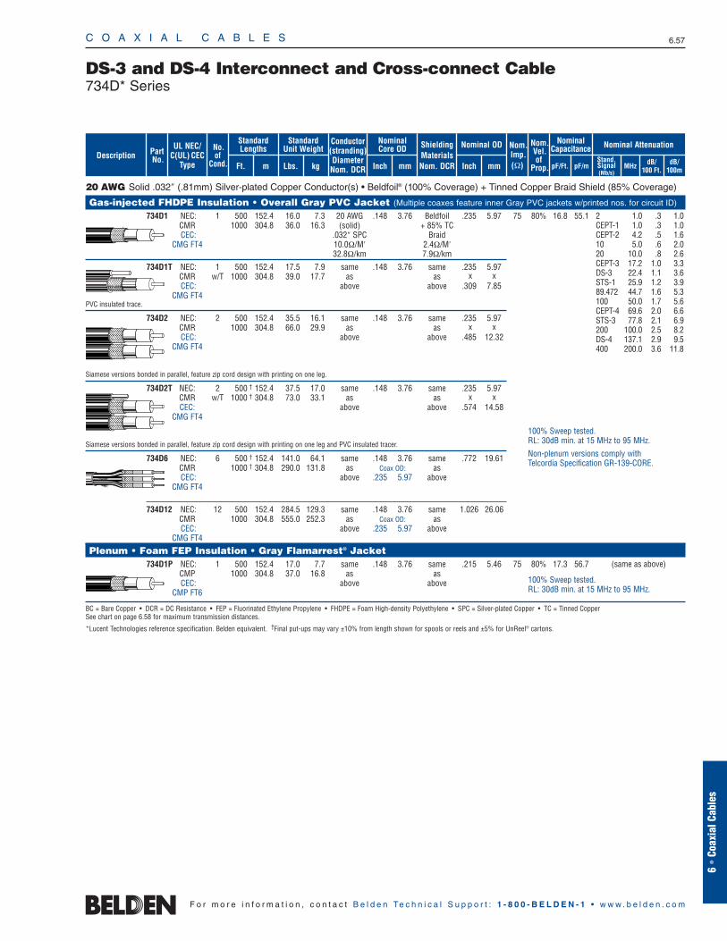
C O A X I A L C A B L E S 6.57
DS-3 and DS-4 Interconnect and Cross-connect Cable734D* Series
6 •
Coax
ial C
able
s
F o r m o r e i n f o r m a t i o n , c o n t a c t B e l d e n Te c h n i c a l S u p p o r t : 1 - 8 0 0 - B E L D E N - 1 • w w w . b e l d e n . c o m
Stand.Signal(Mb/s)
MHz dB/100 Ft.
dB/100m
20 AWG Solid .032″ (.81mm) Silver-plated Copper Conductor(s) • Beldfoil® (100% Coverage) + Tinned Copper Braid Shield (85% Coverage)
Gas-injected FHDPE Insulation • Overall Gray PVC Jacket (Multiple coaxes feature inner Gray PVC jackets w/printed nos. for circuit ID)
734D1 NEC: 1 500 152.4 16.0 7.3 20 AWG .148 3.76 Beldfoil .235 5.97 75 80% 16.8 55.1CMR 1000 304.8 36.0 16.3 (solid) + 85% TCCEC: .032″ SPC Braid
CMG FT4 10.0Ω/M′ 2.4Ω/M′32.8Ω/km 7.9Ω/km
734D1T NEC: 1 500 152.4 17.5 7.9 same .148 3.76 same .235 5.97CMR w/T 1000 304.8 39.0 17.7 as as x xCEC: above above .309 7.85
CMG FT4PVC insulated trace.
734D2 NEC: 2 500 152.4 35.5 16.1 same .148 3.76 same .235 5.97CMR 1000 304.8 66.0 29.9 as as x xCEC: above above .485 12.32
CMG FT4
Siamese versions bonded in parallel, feature zip cord design with printing on one leg.
734D2T NEC: 2 500 † 152.4 37.5 17.0 same .148 3.76 same .235 5.97CMR w/T 1000 † 304.8 73.0 33.1 as as x xCEC: above above .574 14.58
CMG FT4
Siamese versions bonded in parallel, feature zip cord design with printing on one leg and PVC insulated tracer.
734D6 NEC: 6 500 † 152.4 141.0 64.1 same .148 3.76 same .772 19.61CMR 1000 † 304.8 290.0 131.8 as Coax OD: asCEC: above .235 5.97 above
CMG FT4
734D12 NEC: 12 500 152.4 284.5 129.3 same .148 3.76 same 1.026 26.06CMR 1000 304.8 555.0 252.3 as Coax OD: asCEC: above .235 5.97 above
CMG FT4
Plenum • Foam FEP Insulation • Gray Flamarrest® Jacket 734D1P NEC: 1 500 152.4 17.0 7.7 same .148 3.76 same .215 5.46 75 80% 17.3 56.7
CMP 1000 304.8 37.0 16.8 as asCEC: above above
CMP FT6
BC = Bare Copper • DCR = DC Resistance • FEP = Fluorinated Ethylene Propylene • FHDPE = Foam High-density Polyethylene • SPC = Silver-plated Copper • TC = Tinned CopperSee chart on page 6.58 for maximum transmission distances.
*Lucent Technologies reference specification. Belden equivalent. †Final put-ups may vary ±10% from length shown for spools or reels and ±5% for UnReel® cartons.
2 1.0 .3 1.0CEPT-1 1.0 .3 1.0CEPT-2 4.2 .5 1.610 5.0 .6 2.020 10.0 .8 2.6CEPT-3 17.2 1.0 3.3DS-3 22.4 1.1 3.6STS-1 25.9 1.2 3.989.472 44.7 1.6 5.3100 50.0 1.7 5.6CEPT-4 69.6 2.0 6.6STS-3 77.8 2.1 6.9200 100.0 2.5 8.2DS-4 137.1 2.9 9.5400 200.0 3.6 11.8
(same as above)
100% Sweep tested.RL: 30dB min. at 15 MHz to 95 MHz.
Non-plenum versions comply withTelcordia Specification GR-139-CORE.
100% Sweep tested.RL: 30dB min. at 15 MHz to 95 MHz.
Conductor(stranding)DiameterNom. DCR
Nominal Core OD
Inch mm
Nominal OD
Inch mm
ShieldingMaterialsNom. DCR
StandardUnit Weight
kg
No.of
Cond.
Nom.Imp.(Ω)
Standard Lengths
Lbs.Ft. m
UL NEC/C(UL) CEC
Type
PartNo.
Nominal AttenuationNominalCapacitance
pF/mpF/Ft.
Nom.Vel.of
Prop.Description
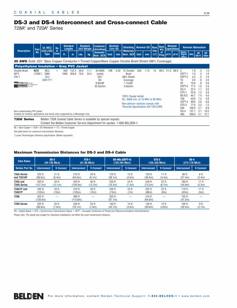
C O A X I A L C A B L E S 6.58
F o r m o r e i n f o r m a t i o n , c o n t a c t B e l d e n Te c h n i c a l S u p p o r t : 1 - 8 0 0 - B E L D E N - 1 • w w w . b e l d e n . c o m
Stand.Signal(Mb/s)
MHz dB/100 Ft.
dB/100m
20 AWG Solid .031″ Bare Copper Conductor • Tinned Copper/Bare Copper Double Braid Shield (98% Coverage)
Polyethylene Insulation • Gray PVC Jacket Double Braid 9231 NEC: 1 500 152.4 39.0 17.7 20 AWG .198 5.03 TC Double .305 7.75 75 66% 21.0 68.960°C (728A*) CMH 1000 304.8 76.0 34.5 (solid) BraidVW-1 CEC: .031″ 98% Shield
CMH FT1 BC Coverage9.9Ω/M′ 1.1Ω/M′
32.5Ω/km 3.6Ω/km
Non-contaminating PVC jacket.Suitable for Outdoor applications and Aerial when supported by a Messenger wire.
720A* Series Belden 720A Coaxial Cable Series is available by special request. Contact the Belden Customer Service Department for quotes. 1-800-BELDEN-1.
BC = Bare Copper • DCR = DC Resistance • TC = Tinned Copper
See table below for maximum transmission distances.
*Lucent Technologies reference specification. Belden equivalent.
DS-3 and DS-4 Interconnect and Cross-connect Cable728A* and 720A* Series
2 1.0 .3 1.0CEPT-1 1.0 .3 1.0CEPT-2 4.2 .5 1.610 5.0 .6 2.020 10.0 .8 2.6CEPT-3 17.2 1.0 3.3DS-3 22.4 1.1 3.6STS-1 25.9 1.2 3.989.472 44.7 1.4 4.6100 50.0 1.5 4.9CEPT-4 69.6 2.0 6.6STS-3 77.8 2.2 7.2200 100.0 2.7 8.9DS-4 137.1 3.1 10.2400 200.0 3.7 12.1
100% Sweep tested.RL: 30dB min. at 15 MHz to 95 MHz.
Non-plenum versions comply withTelcordia Specification GR-139-CORE.
Belden Part No.
Data Rates:
Interconnect X-Connect Interconnect X-Connect Interconnect X-Connect Interconnect X-Connect Interconnect X-Connect
735A Series 225 ft. 21 ft. 210 ft. 20 ft. 125 ft. 13 ft. 120 ft. 11 ft. 90 ft. 8 ft.and 7351AP (68.6m) (6.4m) (64.0m) (6.1m) (38.1m) (4.0m) (36.6m) (3.4m) (27.4m) (2.4m)
734A and 450 ft. 43 ft. 420 ft. 40 ft. 250 ft. 24 ft. 240 ft. 22 ft. 180 ft. 17 ft.734D Series (137.2m) (13.1m) (128.0m) (12.2m) (76.2m) (7.3m) (73.2m) (6.7m) (54.9m) (5.2m)
734A1P and 435 ft. 43 ft. 410 ft. 40 ft. 240 ft. 24 ft. 225 ft. 22 ft. 170 ft. 17 ft.734D1P (132m) (13m) (125m) (12m) (73m) (7m) (68m) (8m) (52m) (5m)
728A 425 ft. — 380 ft. — 220 ft. — 210 ft. — 155 ft. —(129.5m) (115.8m) (67.1m) (64.0m) (47.2m)
720A Series 225 ft. 25 ft. 230 ft. 23 ft. 140 ft. 14 ft. 130 ft. 13 ft. 100 ft. 9 ft.(68.6m) (7.6m) (70.1m) (7.0m) (42.7m) (4.3m) (39.6m) (4.0m) (30.5m) (2.7m)
DS = Digital Signal • STS = Synchronous Transmission Signal • CEPT = European Conference of Postal and Telecommunications Administrations
Please note: The signal loss budget for individual installations will affect the exact transmission distance.
DS-3(44.736 Mb/s)
STS-1(51.86 Mb/s)
DS-4Na (CEPT-4)(139.264 Mb/s)
STS-3(155.520 Mb/s)
DS-4(274.176 Mb/s)
Maximum Transmission Distances for DS-3 and DS-4 Cable
Conductor(stranding)DiameterNom. DCR
Nominal Core OD
Inch mm
Nominal OD
Inch mm
ShieldingMaterialsNom. DCR
StandardUnit Weight
kg
No.of
Cond.
Nom.Imp.(Ω)
Standard Lengths
Lbs.Ft. m
UL NEC/C(UL) CEC
Type
PartNo.
Nominal AttenuationNominalCapacitance
pF/mpF/Ft.
Nom.Vel.of
Prop.Description

RG-174 Type • 25 AWG Solid .018″ Bare Copper Conductor • Beldfoil® (100% Coverage) + Tinned Copper Braid Shield (90% Coverage)
Solid Polyethylene Insulation • Black PVC Jacket RF100A 7805 — 100 † 30.5 1.8 .8 25 AWG .061 1.55 Beldfoil .110 2.79 50 66% 31.2 102.480°C 500 152.4 5.5 2.5 (solid) + 90% TC
1000 304.8 10.0 4.5 .018″ BraidBC 9.1Ω/M′
3.2Ω/M′ 29.9Ω/km10.5Ω/km
Mates with standard RG-174 connectors. Suitable for Aerial applications when supported by a Messenger wire.
RG-174 Type • 24.5 AWG Solid .020″ Bare Copper Conductor • Beldfoil + Tinned Copper Braid Shield (93% Coverage)
Foam HDPE Insulation • Gray PVC Jacket RF100LL 7805R NEC: 100 † 30.5 1.8 .8 24.5 AWG .060 1.52 Beldfoil .110 2.79 50 73.5% 26.2 86.080°C CMR 500 152.4 5.5 2.5 (solid) + 93% TC
CEC: 1000 304.8 10.0 4.5 .020″ BraidCMG FT4 BC 9.3Ω/M′
27.3Ω/M′ 30.5Ω/km94.2Ω/km
Mates with standard RG-174 connectors.
BC = Bare Copper • DCR = DC Resistance • HDPE = High-density Polyethylene • TC = Tinned Copper†May contain more than one piece. Min. length of any one piece is 25 ft.
C O A X I A L C A B L E S 6.59
Low Loss 50 OhmWireless RF Transmission CableRG-174 Type
30 3.8 12.450 4.9 16.1
150 8.6 28.2220 10.4 34.2450 15.2 49.9900 22.0 72.3
1500 28.7 94.31800 31.7 104.02000 33.4 109.72500 37.8 124.23000 42.0 137.84500 52.3 171.55800 60.9 199.86000 62.0 203.3
30 3.5 11.550 4.6 15.0
150 8.0 26.1220 9.6 31.6450 14.0 46.1900 20.2 66.4
1500 26.6 87.31800 29.5 96.72000 31.2 102.32500 35.4 116.33000 39.4 129.24500 50.0 164.25800 59.0 193.66000 60.6 198.7
6 •
Coax
ial C
able
s
F o r m o r e i n f o r m a t i o n , c o n t a c t B e l d e n Te c h n i c a l S u p p o r t : 1 - 8 0 0 - B E L D E N - 1 • w w w . b e l d e n . c o m
100% Sweep tested. 6 GHz. Max. VSWR 1.25:1
Belden® The Wire in Wireless.
100% Sweep tested. 6 GHz. Max. VSWR 1.25:1.
Belden® The Wire in Wireless.
ShieldingMaterialsNom. DCR
Nom.Imp.(Ω)
Nominal Core OD Nominal OD
Inch mm Inch mm
Conductor(stranding)DiameterNom. DCR
StandardUnit WeightStandard Lengths
Lbs. kgFt. m
UL NEC/C(UL) CEC
Type
PartNo.
MHz dB/100 Ft.
dB/100m
Nominal Attenuation
Nominal Capacitance
pF/mpF/Ft.
Nom.Vel.of
Prop.Description
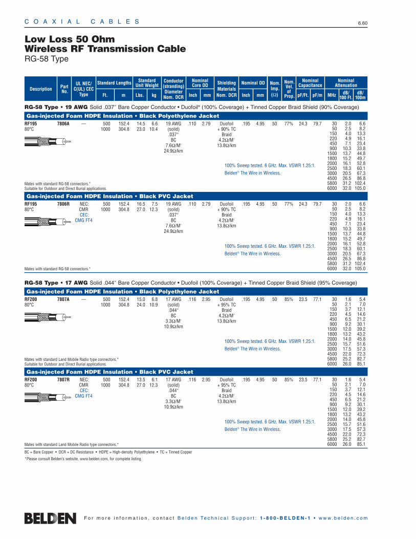
C O A X I A L C A B L E S 6.60
F o r m o r e i n f o r m a t i o n , c o n t a c t B e l d e n Te c h n i c a l S u p p o r t : 1 - 8 0 0 - B E L D E N - 1 • w w w . b e l d e n . c o m
RG-58 Type • 19 AWG Solid .037″ Bare Copper Conductor • Duofoil® (100% Coverage) + Tinned Copper Braid Shield (90% Coverage)
Gas-injected Foam HDPE Insulation • Black Polyethylene JacketRF195 7806A — 500 152.4 14.5 6.6 19 AWG .110 2.79 Duofoil .195 4.95 50 77% 24.3 79.780°C 1000 304.8 23.0 10.4 (solid) + 90% TC
.037″ BraidBC 4.2Ω/M′
7.6Ω/M′ 13.8Ω/km24.9Ω/km
Mates with standard RG-58 connectors.*Suitable for Outdoor and Direct Burial applications.
Gas-injected Foam HDPE Insulation • Black PVC JacketRF195 7806R NEC: 500 152.4 16.5 7.5 19 AWG .110 2.79 Duofoil .195 4.95 50 77% 24.3 79.780°C CMR 1000 304.8 27.0 12.3 (solid) + 90% TC
CEC: .037″ BraidCMG FT4 BC 4.2Ω/M′
7.6Ω/M′ 13.8Ω/km24.9Ω/km
Mates with standard RG-58 connectors.*
RG-58 Type • 17 AWG Solid .044″ Bare Copper Conductor • Duofoil (100% Coverage) + Tinned Copper Braid Shield (95% Coverage)
Gas-injected Foam HDPE Insulation • Black Polyethylene JacketRF200 7807A — 500 152.4 15.0 6.8 17 AWG .116 2.95 Duofoil .195 4.95 50 85% 23.5 77.180°C 1000 304.8 24.0 10.9 (solid) + 95% TC
.044″ BraidBC 4.2Ω/M′
3.3Ω/M′ 13.8Ω/km10.9Ω/km
Mates with standard Land Mobile Radio type connectors.*Suitable for Outdoor and Direct Burial applications.
Gas-injected Foam HDPE Insulation • Black PVC JacketRF200 7807R NEC: 500 152.4 13.5 6.1 17 AWG .116 2.95 Duofoil .195 4.95 50 85% 23.5 77.180°C CMR 1000 304.8 27.0 12.3 (solid) + 95% TC
CEC: .044″ BraidCMG FT4 BC 4.2Ω/M′
3.3Ω/M′ 13.8Ω/km10.9Ω/km
Mates with standard Land Mobile Radio type connectors.*
BC = Bare Copper • DCR = DC Resistance • HDPE = High-density Polyethylene • TC = Tinned Copper
*Please consult Belden’s website, www.belden.com, for complete listing.
Low Loss 50 OhmWireless RF Transmission CableRG-58 Type
30 2.0 6.650 2.5 8.2
150 4.0 13.3220 4.9 16.1450 7.1 23.4900 10.3 33.8
1500 13.7 44.81800 15.2 49.72000 16.1 52.82500 18.3 60.13000 20.5 67.34500 26.5 86.85800 31.2 102.46000 32.0 105.0
30 2.0 6.650 2.5 8.2
150 4.0 13.3220 4.9 16.1450 7.1 23.4900 10.3 33.8
1500 13.7 44.81800 15.2 49.72000 16.1 52.82500 18.3 60.13000 20.5 67.34500 26.5 86.85800 31.2 102.46000 32.0 105.0
30 1.6 5.450 2.1 7.0
150 3.7 12.1220 4.5 14.6450 6.5 21.2900 9.2 30.1
1500 12.0 39.21800 13.2 43.22000 14.0 45.82500 15.7 51.63000 17.5 57.34500 22.0 72.35800 25.2 82.76000 26.0 85.1
30 1.6 5.450 2.1 7.0
150 3.7 12.1220 4.5 14.6450 6.5 21.2900 9.2 30.1
1500 12.0 39.21800 13.2 43.22000 14.0 45.82500 15.7 51.63000 17.5 57.34500 22.0 72.35800 25.2 82.76000 26.0 85.1
100% Sweep tested. 6 GHz. Max. VSWR 1.25:1.
Belden® The Wire in Wireless.
100% Sweep tested. 6 GHz. Max. VSWR 1.25:1.
Belden® The Wire in Wireless.
100% Sweep tested. 6 GHz. Max. VSWR 1.25:1.
Belden® The Wire in Wireless.
100% Sweep tested. 6 GHz. Max. VSWR 1.25:1.
Belden® The Wire in Wireless.
ShieldingMaterialsNom. DCR
Nom.Imp.(Ω)
Nominal Core OD Nominal OD
Inch mm Inch mm
Conductor(stranding)DiameterNom. DCR
StandardUnit WeightStandard Lengths
Lbs. kgFt. m
UL NEC/C(UL) CEC
Type
PartNo.
MHz dB/100 Ft.
dB/100m
Nominal Attenuation
Nominal Capacitance
pF/mpF/Ft.
Nom.Vel.of
Prop.Description
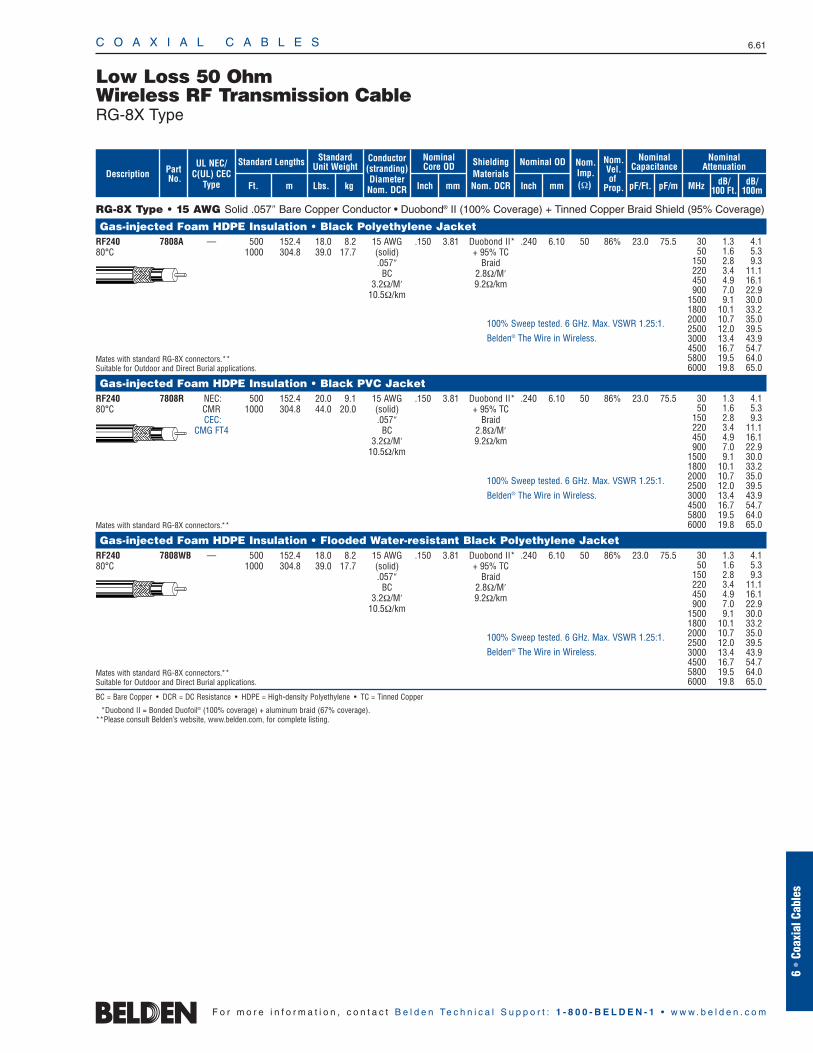
RG-8X Type • 15 AWG Solid .057″ Bare Copper Conductor • Duobond® II (100% Coverage) + Tinned Copper Braid Shield (95% Coverage)
Gas-injected Foam HDPE Insulation • Black Polyethylene JacketRF240 7808A — 500 152.4 18.0 8.2 15 AWG .150 3.81 Duobond II* .240 6.10 50 86% 23.0 75.580°C 1000 304.8 39.0 17.7 (solid) + 95% TC
.057″ BraidBC 2.8Ω/M′
3.2Ω/M′ 9.2Ω/km10.5Ω/km
Mates with standard RG-8X connectors.**Suitable for Outdoor and Direct Burial applications.
Gas-injected Foam HDPE Insulation • Black PVC JacketRF240 7808R NEC: 500 152.4 20.0 9.1 15 AWG .150 3.81 Duobond II* .240 6.10 50 86% 23.0 75.580°C CMR 1000 304.8 44.0 20.0 (solid) + 95% TC
CEC: .057″ BraidCMG FT4 BC 2.8Ω/M′
3.2Ω/M′ 9.2Ω/km10.5Ω/km
Mates with standard RG-8X connectors.**
Gas-injected Foam HDPE Insulation • Flooded Water-resistant Black Polyethylene JacketRF240 7808WB — 500 152.4 18.0 8.2 15 AWG .150 3.81 Duobond II* .240 6.10 50 86% 23.0 75.580°C 1000 304.8 39.0 17.7 (solid) + 95% TC
.057″ BraidBC 2.8Ω/M′
3.2Ω/M′ 9.2Ω/km10.5Ω/km
Mates with standard RG-8X connectors.**Suitable for Outdoor and Direct Burial applications.
BC = Bare Copper • DCR = DC Resistance • HDPE = High-density Polyethylene • TC = Tinned Copper
*Duobond II = Bonded Duofoil® (100% coverage) + aluminum braid (67% coverage).**Please consult Belden’s website, www.belden.com, for complete listing.
C O A X I A L C A B L E S 6.61
6 •
Coax
ial C
able
s
F o r m o r e i n f o r m a t i o n , c o n t a c t B e l d e n Te c h n i c a l S u p p o r t : 1 - 8 0 0 - B E L D E N - 1 • w w w . b e l d e n . c o m
Low Loss 50 OhmWireless RF Transmission CableRG-8X Type
30 1.3 4.150 1.6 5.3
150 2.8 9.3220 3.4 11.1450 4.9 16.1900 7.0 22.9
1500 9.1 30.01800 10.1 33.22000 10.7 35.02500 12.0 39.53000 13.4 43.94500 16.7 54.75800 19.5 64.06000 19.8 65.0
30 1.3 4.150 1.6 5.3
150 2.8 9.3220 3.4 11.1450 4.9 16.1900 7.0 22.9
1500 9.1 30.01800 10.1 33.22000 10.7 35.02500 12.0 39.53000 13.4 43.94500 16.7 54.75800 19.5 64.06000 19.8 65.0
30 1.3 4.150 1.6 5.3
150 2.8 9.3220 3.4 11.1450 4.9 16.1900 7.0 22.9
1500 9.1 30.01800 10.1 33.22000 10.7 35.02500 12.0 39.53000 13.4 43.94500 16.7 54.75800 19.5 64.06000 19.8 65.0
100% Sweep tested. 6 GHz. Max. VSWR 1.25:1.
Belden® The Wire in Wireless.
100% Sweep tested. 6 GHz. Max. VSWR 1.25:1.
Belden® The Wire in Wireless.
100% Sweep tested. 6 GHz. Max. VSWR 1.25:1.
Belden® The Wire in Wireless.
ShieldingMaterialsNom. DCR
Nom.Imp.(Ω)
Nominal Core OD Nominal OD
Inch mm Inch mm
Conductor(stranding)DiameterNom. DCR
StandardUnit WeightStandard Lengths
Lbs. kgFt. m
UL NEC/C(UL) CEC
Type
PartNo.
MHz dB/100 Ft.
dB/100m
Nominal Attenuation
Nominal Capacitance
pF/mpF/Ft.
Nom.Vel.of
Prop.Description
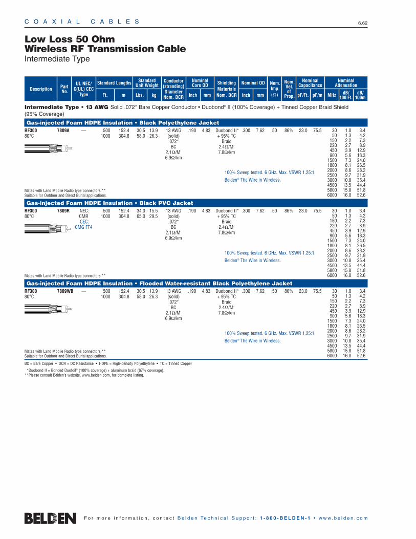
C O A X I A L C A B L E S 6.62
F o r m o r e i n f o r m a t i o n , c o n t a c t B e l d e n Te c h n i c a l S u p p o r t : 1 - 8 0 0 - B E L D E N - 1 • w w w . b e l d e n . c o m
Intermediate Type • 13 AWG Solid .072″ Bare Copper Conductor • Duobond® II (100% Coverage) + Tinned Copper Braid Shield (95% Coverage)
Gas-injected Foam HDPE Insulation • Black Polyethylene JacketRF300 7809A — 500 152.4 30.5 13.9 13 AWG .190 4.83 Duobond II* .300 7.62 50 86% 23.0 75.580°C 1000 304.8 58.0 26.3 (solid) + 95% TC
.072″ BraidBC 2.4Ω/M′
2.1Ω/M′ 7.8Ω/km6.9Ω/km
Mates with Land Mobile Radio type connectors.**Suitable for Outdoor and Direct Burial applications.
Gas-injected Foam HDPE Insulation • Black PVC JacketRF300 7809R NEC: 500 152.4 34.0 15.5 13 AWG .190 4.83 Duobond II* .300 7.62 50 86% 23.0 75.580°C CMR 1000 304.8 65.0 29.5 (solid) + 95% TC
CEC: .072″ BraidCMG FT4 BC 2.4Ω/M′
2.1Ω/M′ 7.8Ω/km6.9Ω/km
Mates with Land Mobile Radio type connectors.**
Gas-injected Foam HDPE Insulation • Flooded Water-resistant Black Polyethylene JacketRF300 7809WB — 500 152.4 30.5 13.9 13 AWG .190 4.83 Duobond II* .300 7.62 50 86% 23.0 75.580°C 1000 304.8 58.0 26.3 (solid) + 95% TC
.072″ BraidBC 2.4Ω/M′
2.1Ω/M′ 7.8Ω/km6.9Ω/km
Mates with Land Mobile Radio type connectors.**Suitable for Outdoor and Direct Burial applications.
BC = Bare Copper • DCR = DC Resistance • HDPE = High-density Polyethylene • TC = Tinned Copper
*Duobond II = Bonded Duofoil® (100% coverage) + aluminum braid (67% coverage).**Please consult Belden’s website, www.belden.com, for complete listing.
Low Loss 50 OhmWireless RF Transmission CableIntermediate Type
30 1.0 3.450 1.3 4.2
150 2.2 7.3220 2.7 8.9450 3.9 12.9900 5.6 18.3
1500 7.3 24.01800 8.1 26.52000 8.6 28.22500 9.7 31.93000 10.8 35.44500 13.5 44.45800 15.8 51.86000 16.0 52.6
30 1.0 3.450 1.3 4.2
150 2.2 7.3220 2.7 8.9450 3.9 12.9900 5.6 18.3
1500 7.3 24.01800 8.1 26.52000 8.6 28.22500 9.7 31.93000 10.8 35.44500 13.5 44.45800 15.8 51.86000 16.0 52.6
30 1.0 3.450 1.3 4.2
150 2.2 7.3220 2.7 8.9450 3.9 12.9900 5.6 18.3
1500 7.3 24.01800 8.1 26.52000 8.6 28.22500 9.7 31.93000 10.8 35.44500 13.5 44.45800 15.8 51.86000 16.0 52.6
100% Sweep tested. 6 GHz. Max. VSWR 1.25:1.
Belden® The Wire in Wireless.
100% Sweep tested. 6 GHz. Max. VSWR 1.25:1.
Belden® The Wire in Wireless.
100% Sweep tested. 6 GHz. Max. VSWR 1.25:1.
Belden® The Wire in Wireless.
ShieldingMaterialsNom. DCR
Nom.Imp.(Ω)
Nominal Core OD Nominal OD
Inch mm Inch mm
Conductor(stranding)DiameterNom. DCR
StandardUnit WeightStandard Lengths
Lbs. kgFt. m
UL NEC/C(UL) CEC
Type
PartNo.
MHz dB/100 Ft.
dB/100m
Nominal Attenuation
Nominal Capacitance
pF/mpF/Ft.
Nom.Vel.of
Prop.Description
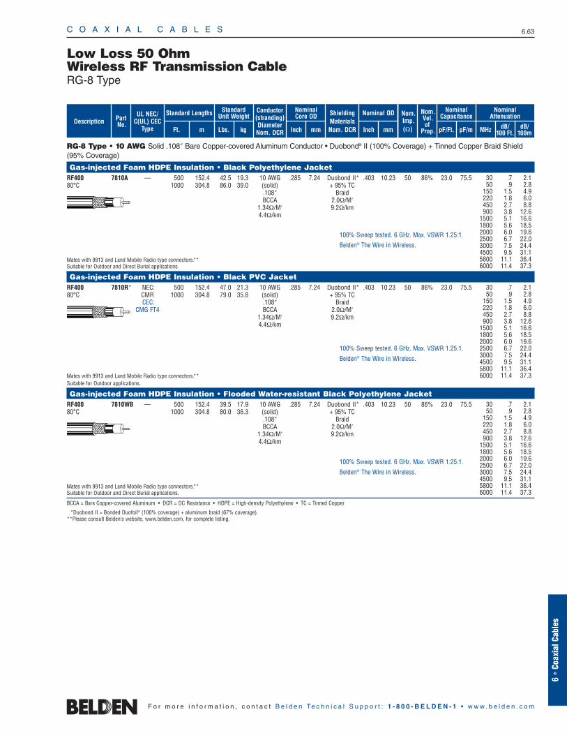
RG-8 Type • 10 AWG Solid .108″ Bare Copper-covered Aluminum Conductor • Duobond® II (100% Coverage) + Tinned Copper Braid Shield(95% Coverage)
Gas-injected Foam HDPE Insulation • Black Polyethylene Jacket RF400 7810A — 500 152.4 42.5 19.3 10 AWG .285 7.24 Duobond II* .403 10.23 50 86% 23.0 75.580°C 1000 304.8 86.0 39.0 (solid) + 95% TC
.108″ BraidBCCA 2.0Ω/M′
1.34Ω/M′ 9.2Ω/km4.4Ω/km
Mates with 9913 and Land Mobile Radio type connectors.**Suitable for Outdoor and Direct Burial applications.
Gas-injected Foam HDPE Insulation • Black PVC Jacket RF400 7810R* NEC: 500 152.4 47.0 21.3 10 AWG .285 7.24 Duobond II* .403 10.23 50 86% 23.0 75.580°C CMR 1000 304.8 79.0 35.8 (solid) + 95% TC
CEC: .108″ BraidCMG FT4 BCCA 2.0Ω/M′
1.34Ω/M′ 9.2Ω/km4.4Ω/km
Mates with 9913 and Land Mobile Radio type connectors.**Suitable for Outdoor applications.
Gas-injected Foam HDPE Insulation • Flooded Water-resistant Black Polyethylene Jacket RF400 7810WB — 500 152.4 39.5 17.9 10 AWG .285 7.24 Duobond II* .403 10.23 50 86% 23.0 75.580°C 1000 304.8 80.0 36.3 (solid) + 95% TC
.108″ BraidBCCA 2.0Ω/M′
1.34Ω/M′ 9.2Ω/km4.4Ω/km
Mates with 9913 and Land Mobile Radio type connectors.**Suitable for Outdoor and Direct Burial applications.
BCCA = Bare Copper-covered Aluminum • DCR = DC Resistance • HDPE = High-density Polyethylene • TC = Tinned Copper
*Duobond II = Bonded Duofoil® (100% coverage) + aluminum braid (67% coverage).**Please consult Belden’s website, www.belden.com, for complete listing.
C O A X I A L C A B L E S 6.63
6 •
Coax
ial C
able
s
F o r m o r e i n f o r m a t i o n , c o n t a c t B e l d e n Te c h n i c a l S u p p o r t : 1 - 8 0 0 - B E L D E N - 1 • w w w . b e l d e n . c o m
Low Loss 50 OhmWireless RF Transmission CableRG-8 Type
30 .7 2.150 .9 2.8
150 1.5 4.9220 1.8 6.0450 2.7 8.8900 3.8 12.6
1500 5.1 16.61800 5.6 18.52000 6.0 19.62500 6.7 22.03000 7.5 24.44500 9.5 31.15800 11.1 36.46000 11.4 37.3
30 .7 2.150 .9 2.8
150 1.5 4.9220 1.8 6.0450 2.7 8.8900 3.8 12.6
1500 5.1 16.61800 5.6 18.52000 6.0 19.62500 6.7 22.03000 7.5 24.44500 9.5 31.15800 11.1 36.46000 11.4 37.3
30 .7 2.150 .9 2.8
150 1.5 4.9220 1.8 6.0450 2.7 8.8900 3.8 12.6
1500 5.1 16.61800 5.6 18.52000 6.0 19.62500 6.7 22.03000 7.5 24.44500 9.5 31.15800 11.1 36.46000 11.4 37.3
100% Sweep tested. 6 GHz. Max. VSWR 1.25:1.
Belden® The Wire in Wireless.
100% Sweep tested. 6 GHz. Max. VSWR 1.25:1.
Belden® The Wire in Wireless.
100% Sweep tested. 6 GHz. Max. VSWR 1.25:1.
Belden® The Wire in Wireless.
ShieldingMaterialsNom. DCR
Nom.Imp.(Ω)
Nominal Core OD Nominal OD
Inch mm Inch mm
Conductor(stranding)DiameterNom. DCR
StandardUnit WeightStandard Lengths
Lbs. kgFt. m
UL NEC/C(UL) CEC
Type
PartNo.
MHz dB/100 Ft.
dB/100m
Nominal Attenuation
Nominal Capacitance
pF/mpF/Ft.
Nom.Vel.of
Prop.Description
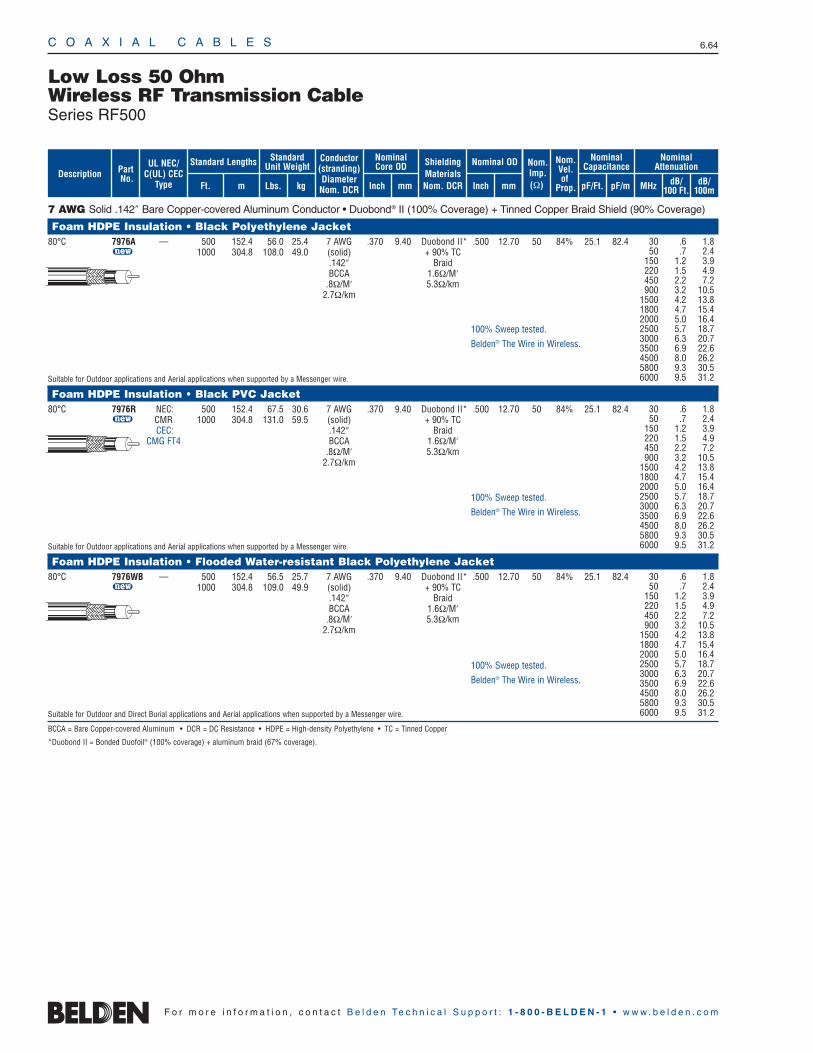
C O A X I A L C A B L E S 6.64
F o r m o r e i n f o r m a t i o n , c o n t a c t B e l d e n Te c h n i c a l S u p p o r t : 1 - 8 0 0 - B E L D E N - 1 • w w w . b e l d e n . c o m
7 AWG Solid .142″ Bare Copper-covered Aluminum Conductor • Duobond® II (100% Coverage) + Tinned Copper Braid Shield (90% Coverage)
Foam HDPE Insulation • Black Polyethylene Jacket 80°C 7976A — 500 152.4 56.0 25.4 7 AWG .370 9.40 Duobond II* .500 12.70 50 84% 25.1 82.4
u 1000 304.8 108.0 49.0 (solid) + 90% TC.142″ BraidBCCA 1.6Ω/M′
.8Ω/M′ 5.3Ω/km2.7Ω/km
Suitable for Outdoor applications and Aerial applications when supported by a Messenger wire.
Foam HDPE Insulation • Black PVC Jacket 80°C 7976R NEC: 500 152.4 67.5 30.6 7 AWG .370 9.40 Duobond II* .500 12.70 50 84% 25.1 82.4
u CMR 1000 304.8 131.0 59.5 (solid) + 90% TCCEC: .142″ Braid
CMG FT4 BCCA 1.6Ω/M′.8Ω/M′ 5.3Ω/km
2.7Ω/km
Suitable for Outdoor applications and Aerial applications when supported by a Messenger wire.
Foam HDPE Insulation • Flooded Water-resistant Black Polyethylene Jacket 80°C 7976WB — 500 152.4 56.5 25.7 7 AWG .370 9.40 Duobond II* .500 12.70 50 84% 25.1 82.4
u 1000 304.8 109.0 49.9 (solid) + 90% TC.142″ BraidBCCA 1.6Ω/M′
.8Ω/M′ 5.3Ω/km2.7Ω/km
Suitable for Outdoor and Direct Burial applications and Aerial applications when supported by a Messenger wire.
BCCA = Bare Copper-covered Aluminum • DCR = DC Resistance • HDPE = High-density Polyethylene • TC = Tinned Copper
*Duobond II = Bonded Duofoil® (100% coverage) + aluminum braid (67% coverage).
Low Loss 50 OhmWireless RF Transmission CableSeries RF500
30 .6 1.850 .7 2.4
150 1.2 3.9220 1.5 4.9450 2.2 7.2900 3.2 10.5
1500 4.2 13.81800 4.7 15.42000 5.0 16.42500 5.7 18.73000 6.3 20.73500 6.9 22.64500 8.0 26.25800 9.3 30.56000 9.5 31.2
30 .6 1.850 .7 2.4
150 1.2 3.9220 1.5 4.9450 2.2 7.2900 3.2 10.5
1500 4.2 13.81800 4.7 15.42000 5.0 16.42500 5.7 18.73000 6.3 20.73500 6.9 22.64500 8.0 26.25800 9.3 30.56000 9.5 31.2
100% Sweep tested.
Belden® The Wire in Wireless.
100% Sweep tested.
Belden® The Wire in Wireless.
100% Sweep tested.
Belden® The Wire in Wireless.
ShieldingMaterialsNom. DCR
Nom.Imp.(Ω)
Nominal Core OD Nominal OD
Inch mm Inch mm
Conductor(stranding)DiameterNom. DCR
StandardUnit WeightStandard Lengths
Lbs. kgFt. m
UL NEC/C(UL) CEC
Type
PartNo.
MHz dB/100 Ft.
dB/100m
Nominal Attenuation
Nominal Capacitance
pF/mpF/Ft.
Nom.Vel.of
Prop.Description
30 .6 1.850 .7 2.4
150 1.2 3.9220 1.5 4.9450 2.2 7.2900 3.2 10.5
1500 4.2 13.81800 4.7 15.42000 5.0 16.42500 5.7 18.73000 6.3 20.73500 6.9 22.64500 8.0 26.25800 9.3 30.56000 9.5 31.2
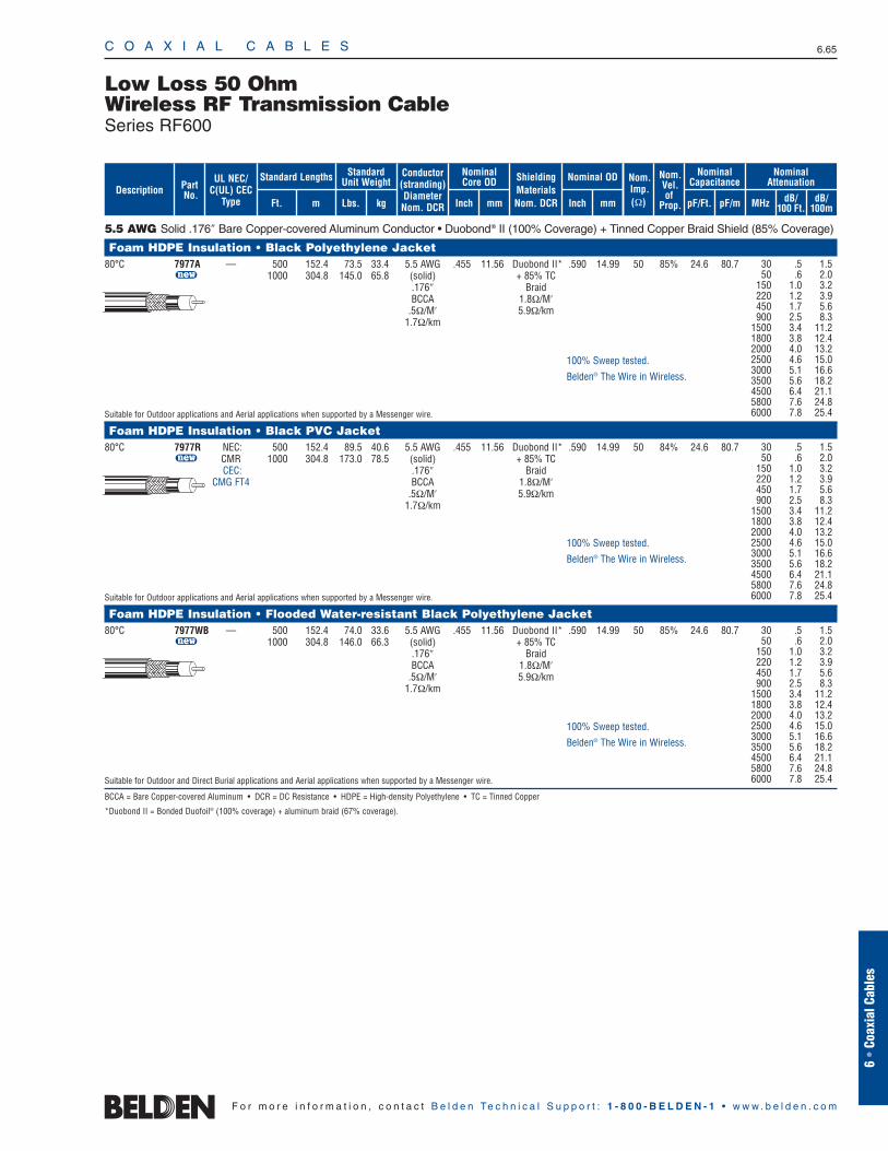
C O A X I A L C A B L E S 6.65
6 •
Coax
ial C
able
s
F o r m o r e i n f o r m a t i o n , c o n t a c t B e l d e n Te c h n i c a l S u p p o r t : 1 - 8 0 0 - B E L D E N - 1 • w w w . b e l d e n . c o m
5.5 AWG Solid .176″ Bare Copper-covered Aluminum Conductor • Duobond® II (100% Coverage) + Tinned Copper Braid Shield (85% Coverage)
Foam HDPE Insulation • Black Polyethylene Jacket 80°C 7977A — 500 152.4 73.5 33.4 5.5 AWG .455 11.56 Duobond II* .590 14.99 50 85% 24.6 80.7
u 1000 304.8 145.0 65.8 (solid) + 85% TC.176″ BraidBCCA 1.8Ω/M′
.5Ω/M′ 5.9Ω/km1.7Ω/km
Suitable for Outdoor applications and Aerial applications when supported by a Messenger wire.
Foam HDPE Insulation • Black PVC Jacket 80°C 7977R NEC: 500 152.4 89.5 40.6 5.5 AWG .455 11.56 Duobond II* .590 14.99 50 84% 24.6 80.7
u CMR 1000 304.8 173.0 78.5 (solid) + 85% TCCEC: .176″ Braid
CMG FT4 BCCA 1.8Ω/M′.5Ω/M′ 5.9Ω/km
1.7Ω/km
Suitable for Outdoor applications and Aerial applications when supported by a Messenger wire.
Foam HDPE Insulation • Flooded Water-resistant Black Polyethylene Jacket 80°C 7977WB — 500 152.4 74.0 33.6 5.5 AWG .455 11.56 Duobond II* .590 14.99 50 85% 24.6 80.7
u 1000 304.8 146.0 66.3 (solid) + 85% TC.176″ BraidBCCA 1.8Ω/M′
.5Ω/M′ 5.9Ω/km1.7Ω/km
Suitable for Outdoor and Direct Burial applications and Aerial applications when supported by a Messenger wire.
BCCA = Bare Copper-covered Aluminum • DCR = DC Resistance • HDPE = High-density Polyethylene • TC = Tinned Copper
*Duobond II = Bonded Duofoil® (100% coverage) + aluminum braid (67% coverage).
Low Loss 50 OhmWireless RF Transmission CableSeries RF600
30 .5 1.550 .6 2.0
150 1.0 3.2220 1.2 3.9450 1.7 5.6900 2.5 8.3
1500 3.4 11.21800 3.8 12.42000 4.0 13.22500 4.6 15.03000 5.1 16.63500 5.6 18.24500 6.4 21.15800 7.6 24.86000 7.8 25.4
30 .5 1.550 .6 2.0
150 1.0 3.2220 1.2 3.9450 1.7 5.6900 2.5 8.3
1500 3.4 11.21800 3.8 12.42000 4.0 13.22500 4.6 15.03000 5.1 16.63500 5.6 18.24500 6.4 21.15800 7.6 24.86000 7.8 25.4
100% Sweep tested.
Belden® The Wire in Wireless.
100% Sweep tested.
Belden® The Wire in Wireless.
100% Sweep tested.
Belden® The Wire in Wireless.
ShieldingMaterialsNom. DCR
Nom.Imp.(Ω)
Nominal Core OD Nominal OD
Inch mm Inch mm
Conductor(stranding)DiameterNom. DCR
StandardUnit WeightStandard Lengths
Lbs. kgFt. m
UL NEC/C(UL) CEC
Type
PartNo.
MHz dB/100 Ft.
dB/100m
Nominal Attenuation
Nominal Capacitance
pF/mpF/Ft.
Nom.Vel.of
Prop.Description
30 .5 1.550 .6 2.0
150 1.0 3.2220 1.2 3.9450 1.7 5.6900 2.5 8.3
1500 3.4 11.21800 3.8 12.42000 4.0 13.22500 4.6 15.03000 5.1 16.63500 5.6 18.24500 6.4 21.15800 7.6 24.86000 7.8 25.4
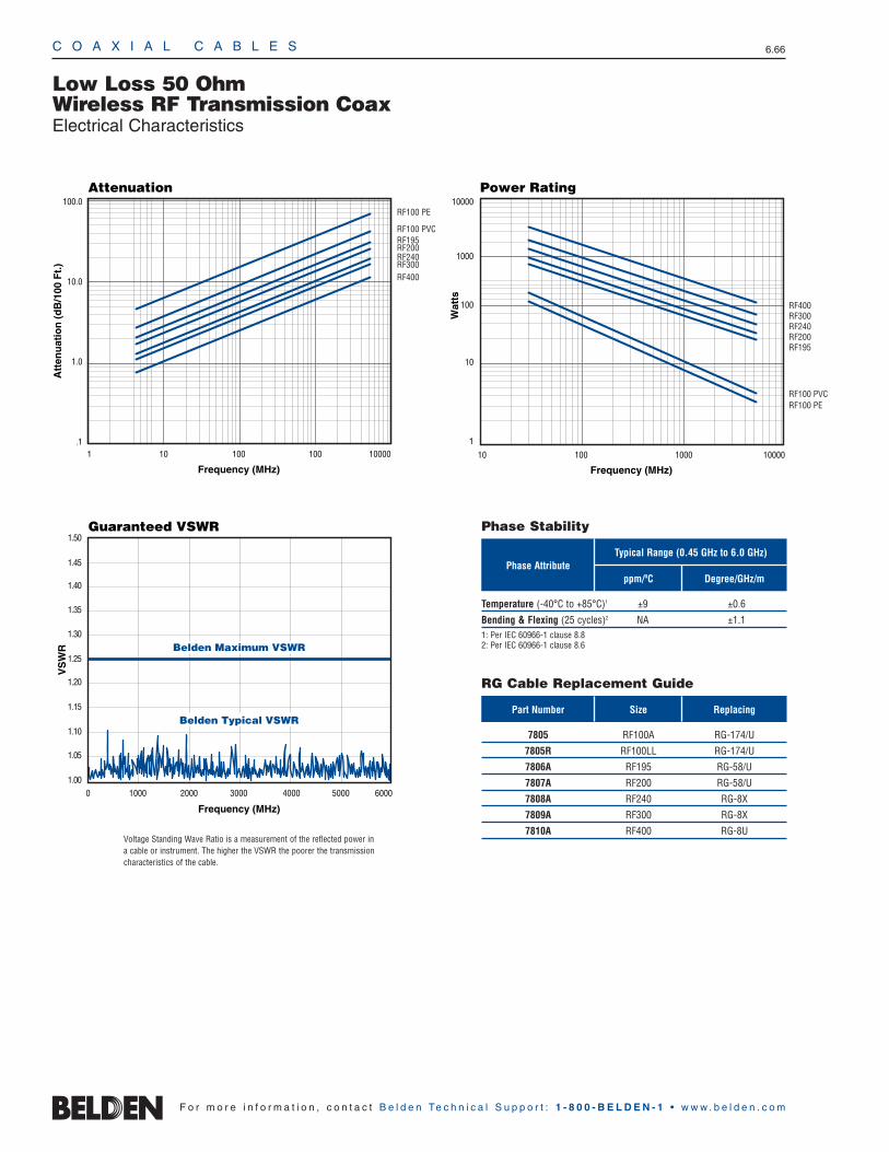
C O A X I A L C A B L E S 6.66
F o r m o r e i n f o r m a t i o n , c o n t a c t B e l d e n Te c h n i c a l S u p p o r t : 1 - 8 0 0 - B E L D E N - 1 • w w w . b e l d e n . c o m
Low Loss 50 OhmWireless RF Transmission CoaxElectrical Characteristics
Phase Attribute
Part Number Size Replacing
ppm/ºC Degree/GHz/m
Typical Range (0.45 GHz to 6.0 GHz)
RF100 PVCRF195RF200RF240RF300RF400
RF100 PE
Frequency (MHz)
Attenuation
Att
enu
atio
n (
dB
/100
Ft.
)
100.0
10.0
1.0
.11 10 100 100 10000
1.000 1000 2000 3000 50004000 6000
1.10
1.05
1.25
1.20
1.15
1.35
1.30
1.50
1.45
1.40
Frequency (MHz)
VS
WR
Guaranteed VSWR
Belden Maximum VSWR
Belden Typical VSWR
1
10 100 1000 10000
10
100
1000
10000
Frequency (MHz)
Wat
ts
RF100 PERF100 PVC
RF400RF300RF240RF200RF195
Power Rating
Temperature (-40°C to +85°C)1 ±9 ±0.6
Bending & Flexing (25 cycles)2 NA ±1.11: Per IEC 60966-1 clause 8.82: Per IEC 60966-1 clause 8.6
Phase Stability
RG Cable Replacement Guide
7805 RF100A RG-174/U
7805R RF100LL RG-174/U
7806A RF195 RG-58/U
7807A RF200 RG-58/U
7808A RF240 RG-8X
7809A RF300 RG-8X
7810A RF400 RG-8UVoltage Standing Wave Ratio is a measurement of the reflected power in a cable or instrument. The higher the VSWR the poorer the transmission characteristics of the cable.
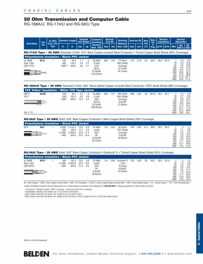
RG-174/U Type • 26 AWG Stranded (7x34) .019″ Bare Copper-covered Steel Conductor • Tinned Copper Braid Shield (90% Coverage)
Polyethylene Insulation • Black PVC Jacket UL AWM 8216 — 100 30.5 1.1 .5 26 AWG .060 1.52 TC Braid .110 2.79 50 66% 30.8 101.0Style 1354 500 152.4 5.0 2.3 (7x34) 90% Shield(30V 75°C) 1000 †† 304.8 9.0 4.1 .019″ Coverage
BCCS 10.7Ω/M′97.0Ω/M′ 35.1Ω/km
318.2Ω/km
RG-188A/U Type • 26 AWG Stranded (7x34) .020″ Silver-plated Copper-covered Steel Conductor • SPC Braid Shield (96% Coverage)
TFE Teflon® Insulation • White TFE Tape Jacket 200°C 83269 — 100 † 30.5 2.0 .9 26 AWG .058 1.47 SPC Braid .098 2.49 50 69.5% 29.0 95.1VW-1 500 † 152.4 6.5 2.9 (7x34) 96% Shield
1000 † 304.8 12.0 5.5 .020″ CoverageSCCCS 8.5Ω/M′
91.2Ω/M′ 27.9Ω/km299.2Ω/km
MIL-C-17D
RG-58/U Type • 20 AWG Solid .033″ Bare Copper Conductor • Bare Copper Braid Shield (78% Coverage)
Polyethylene Insulation • Black PVC Jacket 80°C 9201 — U-500 U-152.4 13.0 5.9 20 AWG .116 2.95 BC Braid .193 4.90 51.5 66% 28.5 93.5
500 152.4 11.5 5.2 (solid) 78% ShieldU-1000 U-304.8 25.0 11.4 .033″ Coverage
1000 304.8 23.0 10.4 BC 5.5Ω/M′10.0Ω/M′ 18.0Ω/km33.1Ω/km
RG-58/U Type • 20 AWG Solid .033″ Bare Copper Conductor • Duobond® II + Tinned Copper Braid Shield (55% Coverage)
Polyethylene Insulation • Black PVC Jacket UL AWM 9310** — 500 152.4 10.5 4.8 20 AWG .114 2.90 Duobond II* .193 4.90 50 66% 30.8 101.0Style 1354 U-1000 U-304.8 22.0 10.0 (solid) + 55%(30V 60°C) 1000 304.8 21.0 9.5 .033″ TC Braid
BC 8.0Ω/M′9.4Ω/M′ 24.4Ω/km
28.6Ω/km
BC = Bare Copper • BCCS = Bare Copper-covered Steel • DCR = DC Resistance • SCCCS = Silver-coated Copper-covered Steel • SPC = Silver-plated Copper • TC = Tinned Copper • TFE = Tetra Fluoroethylene
Contact the Belden Customer Service Department for a Comprehensive Connector Cross Reference. 1-800-BELDEN-1. Request quotations of RG/U cables not listed.
*Duobond II = Bonded Duofoil® (100% coverage) + aluminum braid (67% coverage).**See Belden’s website, www.belden.com, for connector information.
† May contain more than one piece, min. length of any one piece is 25 ft.††May contain more than one piece, min. length of any one piece is 100 ft. Length may vary ±10% from length shown.
C O A X I A L C A B L E S 6.67
6 •
Coax
ial C
able
s
F o r m o r e i n f o r m a t i o n , c o n t a c t B e l d e n Te c h n i c a l S u p p o r t : 1 - 8 0 0 - B E L D E N - 1 • w w w . b e l d e n . c o m
50 Ohm Transmission and Computer CableRG-188A/U, RG-174/U and RG-58/U Type
1 1.9 6.210 3.3 10.850 5.8 19.0
100 8.4 27.6200 12.5 41.0400 19.0 62.3700 27.0 88.6900 31.0 101.7
1000 34.0 111.5
1 1.2 3.910 2.7 8.950 5.6 18.4
100 8.3 27.2200 12.0 39.4400 17.5 57.4700 23.7 77.8900 27.3 89.6
1000 29.0 95.1
Teflon is a DuPont trademark.
1 .3 1.110 1.1 3.650 2.5 8.2
100 3.8 12.5200 5.6 18.4400 8.4 27.6700 11.7 38.4900 13.7 44.9
1000 14.5 47.6
1 .5 1.510 1.4 4.650 2.8 9.2
100 3.8 12.5200 5.4 17.7400 7.9 25.9700 11.1 36.4900 12.8 42.0
1000 13.9 45.6
ShieldingMaterialsNom. DCR
Nom.Imp.(Ω)
Nominal Core OD Nominal OD
Inch mm Inch mm
Conductor(stranding)DiameterNom. DCR
StandardUnit WeightStandard Lengths
Lbs. kgFt. m
UL NEC/C(UL) CEC
Type
PartNo.
MHz dB/100 Ft.
dB/100m
Nominal Attenuation
Nominal Capacitance
pF/mpF/Ft.
Nom.Vel.of
Prop.Description
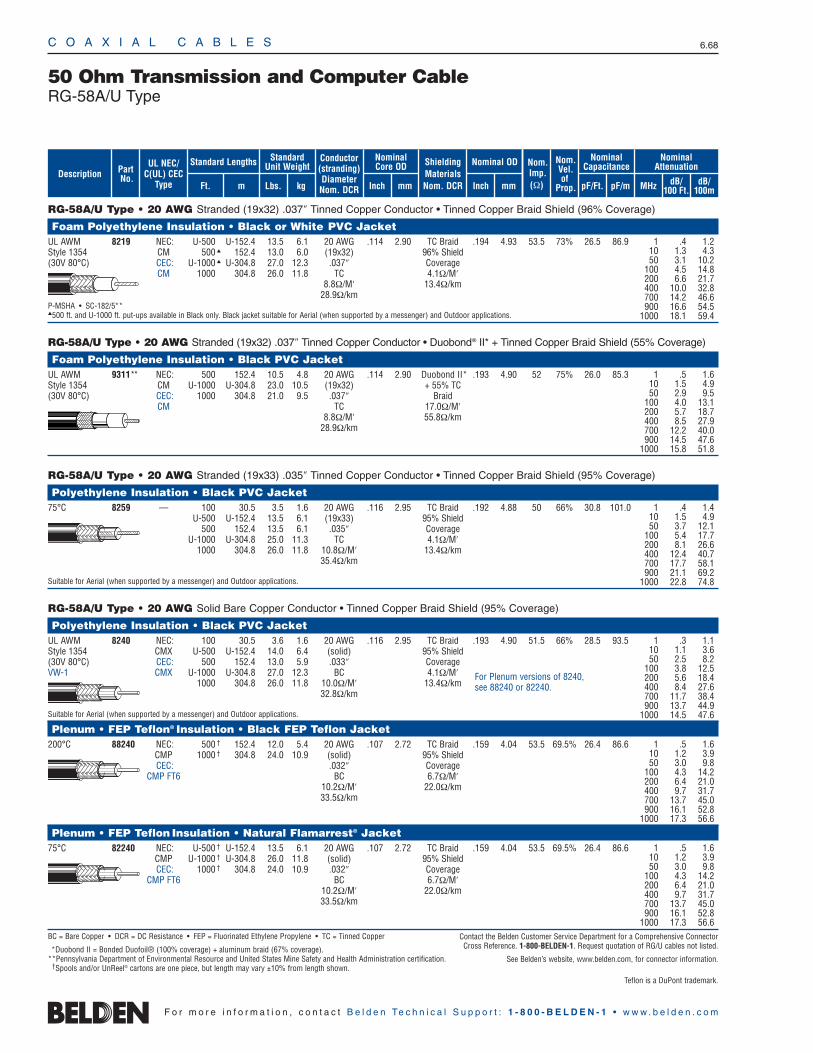
C O A X I A L C A B L E S 6.68
F o r m o r e i n f o r m a t i o n , c o n t a c t B e l d e n Te c h n i c a l S u p p o r t : 1 - 8 0 0 - B E L D E N - 1 • w w w . b e l d e n . c o m
RG-58A/U Type • 20 AWG Stranded (19x32) .037″ Tinned Copper Conductor • Tinned Copper Braid Shield (96% Coverage)
Foam Polyethylene Insulation • Black or White PVC JacketUL AWM 8219 NEC: U-500 U-152.4 13.5 6.1 20 AWG .114 2.90 TC Braid .194 4.93 53.5 73% 26.5 86.9Style 1354 CM 500 152.4 13.0 6.0 (19x32) 96% Shield(30V 80°C) CEC: U-1000 U-304.8 27.0 12.3 .037″ Coverage
CM 1000 304.8 26.0 11.8 TC 4.1Ω/M′8.8Ω/M′ 13.4Ω/km
28.9Ω/kmP-MSHA • SC-182/5**500 ft. and U-1000 ft. put-ups available in Black only. Black jacket suitable for Aerial (when supported by a messenger) and Outdoor applications.
RG-58A/U Type • 20 AWG Stranded (19x32) .037″ Tinned Copper Conductor • Duobond® II* + Tinned Copper Braid Shield (55% Coverage)
Foam Polyethylene Insulation • Black PVC Jacket UL AWM 9311** NEC: 500 152.4 10.5 4.8 20 AWG .114 2.90 Duobond II* .193 4.90 52 75% 26.0 85.3Style 1354 CM U-1000 U-304.8 23.0 10.5 (19x32) + 55% TC(30V 80°C) CEC: 1000 304.8 21.0 9.5 .037″ Braid
CM TC 17.0Ω/M′8.8Ω/M′ 55.8Ω/km
28.9Ω/km
RG-58A/U Type • 20 AWG Stranded (19x33) .035″ Tinned Copper Conductor • Tinned Copper Braid Shield (95% Coverage)
Polyethylene Insulation • Black PVC Jacket 75°C 8259 — 100 30.5 3.5 1.6 20 AWG .116 2.95 TC Braid .192 4.88 50 66% 30.8 101.0
U-500 U-152.4 13.5 6.1 (19x33) 95% Shield500 152.4 13.5 6.1 .035″ Coverage
U-1000 U-304.8 25.0 11.3 TC 4.1Ω/M′1000 304.8 26.0 11.8 10.8Ω/M′ 13.4Ω/km
35.4Ω/km
Suitable for Aerial (when supported by a messenger) and Outdoor applications.
RG-58A/U Type • 20 AWG Solid Bare Copper Conductor • Tinned Copper Braid Shield (95% Coverage)
Polyethylene Insulation • Black PVC JacketUL AWM 8240 NEC: 100 30.5 3.6 1.6 20 AWG .116 2.95 TC Braid .193 4.90 51.5 66% 28.5 93.5Style 1354 CMX U-500 U-152.4 14.0 6.4 (solid) 95% Shield(30V 80°C) CEC: 500 152.4 13.0 5.9 .033″ CoverageVW-1 CMX U-1000 U-304.8 27.0 12.3 BC 4.1Ω/M′
1000 304.8 26.0 11.8 10.0Ω/M′ 13.4Ω/km32.8Ω/km
Suitable for Aerial (when supported by a messenger) and Outdoor applications.
Plenum • FEP Teflon® Insulation • Black FEP Teflon Jacket200°C 88240 NEC: 500 † 152.4 12.0 5.4 20 AWG .107 2.72 TC Braid .159 4.04 53.5 69.5% 26.4 86.6
CMP 1000 † 304.8 24.0 10.9 (solid) 95% ShieldCEC: .032″ Coverage
CMP FT6 BC 6.7Ω/M′10.2Ω/M′ 22.0Ω/km33.5Ω/km
Plenum • FEP Teflon Insulation • Natural Flamarrest® Jacket75°C 82240 NEC: U-500 † U-152.4 13.5 6.1 20 AWG .107 2.72 TC Braid .159 4.04 53.5 69.5% 26.4 86.6
CMP U-1000 † U-304.8 26.0 11.8 (solid) 95% ShieldCEC: 1000 † 304.8 24.0 10.9 .032″ Coverage
CMP FT6 BC 6.7Ω/M′10.2Ω/M′ 22.0Ω/km33.5Ω/km
BC = Bare Copper • DCR = DC Resistance • FEP = Fluorinated Ethylene Propylene • TC = Tinned Copper
*Duobond II = Bonded Duofoil® (100% coverage) + aluminum braid (67% coverage).**Pennsylvania Department of Environmental Resource and United States Mine Safety and Health Administration certification.
†Spools and/or UnReel® cartons are one piece, but length may vary ±10% from length shown.
50 Ohm Transmission and Computer CableRG-58A/U Type
1 .3 1.110 1.1 3.650 2.5 8.2
100 3.8 12.5200 5.6 18.4400 8.4 27.6700 11.7 38.4900 13.7 44.9
1000 14.5 47.6
1 .5 1.610 1.2 3.950 3.0 9.8
100 4.3 14.2200 6.4 21.0400 9.7 31.7700 13.7 45.0900 16.1 52.8
1000 17.3 56.6
1 .5 1.610 1.2 3.950 3.0 9.8
100 4.3 14.2200 6.4 21.0400 9.7 31.7700 13.7 45.0900 16.1 52.8
1000 17.3 56.6
For Plenum versions of 8240, see 88240 or 82240.
1 .4 1.210 1.3 4.350 3.1 10.2
100 4.5 14.8200 6.6 21.7400 10.0 32.8700 14.2 46.6900 16.6 54.5
1000 18.1 59.4
1 .5 1.610 1.5 4.950 2.9 9.5
100 4.0 13.1200 5.7 18.7400 8.5 27.9700 12.2 40.0900 14.5 47.6
1000 15.8 51.8
1 .4 1.410 1.5 4.950 3.7 12.1
100 5.4 17.7200 8.1 26.6400 12.4 40.7700 17.7 58.1900 21.1 69.2
1000 22.8 74.8
ShieldingMaterialsNom. DCR
Nom.Imp.(Ω)
Nominal Core OD Nominal OD
Inch mm Inch mm
Conductor(stranding)DiameterNom. DCR
StandardUnit WeightStandard Lengths
Lbs. kgFt. m
UL NEC/C(UL) CEC
Type
PartNo.
MHz dB/100 Ft.
dB/100m
Nominal Attenuation
Nominal Capacitance
pF/mpF/Ft.
Nom.Vel.of
Prop.Description
Contact the Belden Customer Service Department for a Comprehensive Connector Cross Reference. 1-800-BELDEN-1. Request quotation of RG/U cables not listed.
See Belden’s website, www.belden.com, for connector information.
Teflon is a DuPont trademark.
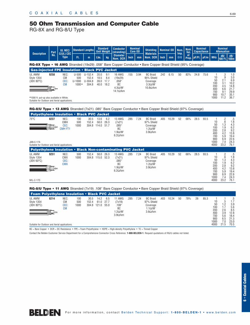
RG-8X Type • 16 AWG Stranded (19x29) .058″ Bare Copper Conductor • Bare Copper Braid Shield (95% Coverage)
Gas-injected FPE Insulation • Black PVC JacketUL AWM 9258 NEC: U-500 U-152.4 20.0 9.1 16 AWG .155 3.94 BC Braid .242 6.15 50 82% 24.8 75.6Style 1354 CM 500 152.4 18.5 8.4 (19x29) 95% Shield(30V 80°C) CEC: U-1000 U-304.8 39.0 17.7 .058″ Coverage
CM 1000 304.8 40.0 18.2 BC 3.3Ω/M′4.3Ω/M′ 10.8Ω/km
14.1Ω/km
1000 ft. put-up also available in White.Suitable for Outdoor and Aerial applications.
RG-8/U Type • 13 AWG Stranded (7x21) .085″ Bare Copper Conductor • Bare Copper Braid Shield (97% Coverage)
Polyethylene Insulation • Black PVC Jacket75°C 8237 NEC: 100 30.5 13.6 6.2 13 AWG .285 7.24 BC Braid .405 10.29 52 66% 28.5 93.5
CMH 500 152.4 58.0 26.3 (7x21) 97% ShieldCEC: 1000 304.8 114.0 51.7 .085″ Coverage
CMH FT1 BC 1.2Ω/M′1.9Ω/M′ 3.9Ω/km6.2Ω/km
JAN-C-17ASuitable for Outdoor and Aerial applications.
Polyethylene Insulation • Black Non-contaminating PVC JacketUL AWM 9251 NEC: 500 152.4 58.0 26.3 13 AWG .285 7.24 BC Braid .405 10.29 52 66% 28.5 93.5Style 1354 CMX 1000 304.8 115.0 52.3 (7x21) 97% Shield(30V 60°C) CEC: .085″ Coverage
CMX BC 1.2Ω/M′1.9Ω/M′ 3.9Ω/km6.2Ω/km
MIL-C-17D
RG-8/U Type • 11 AWG Stranded (7x19) .108″ Bare Copper Conductor • Bare Copper Braid Shield (97% Coverage)
Foam Polyethylene Insulation • Black PVC Jacket UL AWM 8214 NEC: 100 30.5 14.2 6.5 11 AWG .285 7.24 BC Braid .403 10.24 50 78% 26 85.3Style 1354 CM 500 152.4 61.0 27.7 (7x19) 97% Shield(30V 80°C) CEC: 1000 304.8 121.0 55.0 .108″ Coverage
CM BC 1.1Ω/M′1.2Ω/M′ 3.6Ω/km3.9Ω/km
Suitable for Outdoor and Aerial applications.
BC = Bare Copper • DCR = DC Resistance • FPE = Foam Polyethylene • HDPE = High-density Polyethylene • TC = Tinned Copper
Contact the Belden Customer Service Department for a Comprehensive Connector Cross Reference. 1-800-BELDEN-1. Request quotations of RG/U cables not listed.
C O A X I A L C A B L E S 6.69
6 •
Coax
ial C
able
s
F o r m o r e i n f o r m a t i o n , c o n t a c t B e l d e n Te c h n i c a l S u p p o r t : 1 - 8 0 0 - B E L D E N - 1 • w w w . b e l d e n . c o m
50 Ohm Transmission and Computer CableRG-8X and RG-8/U Type
1 .3 1.010 .9 3.050 2.1 6.9
100 3.1 10.2200 4.5 14.8400 6.6 21.7700 9.1 29.9900 10.7 35.1
1000 11.2 36.7
1 .2 .510 .6 1.850 1.3 4.3
100 1.9 6.2200 2.8 9.2400 4.2 13.8700 5.9 19.4900 6.9 22.6
1000 7.4 24.34000 23.2 76.1
1 .2 .510 .6 1.850 1.3 4.3
100 1.9 6.2200 2.8 9.2400 4.2 13.8700 5.9 19.4900 6.9 22.6
1000 7.4 24.34000 23.2 76.1
1 .1 .510 .5 1.750 1.2 3.9
100 1.7 5.6200 2.6 8.5400 3.9 12.8700 5.6 18.4900 6.5 21.3
1000 7.0 23.04000 21.5 70.5
ShieldingMaterialsNom. DCR
Nom.Imp.(Ω)
Nominal Core OD Nominal OD
Inch mm Inch mm
Conductor(stranding)DiameterNom. DCR
StandardUnit WeightStandard Lengths
Lbs. kgFt. m
UL NEC/C(UL) CEC
Type
PartNo.
MHz dB/100 Ft.
dB/100m
Nominal Attenuation
Nominal Capacitance
pF/mpF/Ft.
Nom.Vel.of
Prop.Description
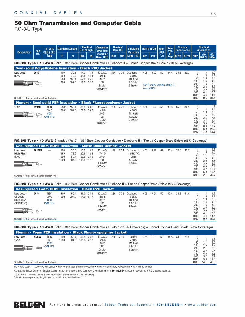
C O A X I A L C A B L E S 6.70
F o r m o r e i n f o r m a t i o n , c o n t a c t B e l d e n Te c h n i c a l S u p p o r t : 1 - 8 0 0 - B E L D E N - 1 • w w w . b e l d e n . c o m
RG-8/U Type • 10 AWG Solid .108″ Bare Copper Conductor • Duobond® II + Tinned Copper Braid Shield (90% Coverage)
Semi-solid Polyethylene Insulation • Black PVC JacketLow Loss 9913 — 100 30.5 14.2 6.4 10 AWG .286 7.26 Duobond II* .405 10.29 50 84% 24.6 80.780°C 250 76.2 31.8 14.4 (solid) + 90%
500 152.4 57.0 25.9 .108″ TC Braid1000 304.8 116.0 52.6 BC 1.8Ω/M′
.9Ω/M′ 5.9Ω/km3.0Ω/km
Suitable for Outdoor and Aerial applications.
Plenum • Semi-solid FEP Insulation • Black Fluorocopolymer Jacket150°C 89913 NEC: 500 † 152.4 63.0 28.6 10 AWG .295 7.49 Duobond II* .364 9.25 50 83% 25.0 82.0
CMP 1000 † 304.8 128.0 58.2 (solid) + 90%CEC: .108″ TC Braid
CMP FT6 BC 1.8Ω/M′.9Ω/M′ 5.9Ω/km
3.0Ω/km
RG-8/U Type • 10 AWG Stranded (7x19) .108″ Bare Copper Conductor • Duobond II + Tinned Copper Braid Shield (95% Coverage)
Gas-injected Foam HDPE Insulation • Matte Black Belflex® Jacket Low Loss 9913F7 — 100 30.5 12.5 5.7 10 AWG .285 7.24 Duobond II* .405 10.29 52 85% 22.5 80.7High-Flex 250 76.2 27.8 12.6 (7x19) + 95% TC80°C 500 152.4 52.5 23.8 .108″ Braid
1000 304.8 104.0 47.2 BC 1.8Ω/M′1.1Ω/M′ 5.9Ω/km3.7Ω/km
Suitable for Outdoor and Aerial applications.
RG-8/U Type • 10 AWG Solid .103″ Bare Copper Conductor • Duobond II + Tinned Copper Braid Shield (95% Coverage)
Gas-injected Foam HDPE Insulation • Black PVC JacketLow Loss 9914 NEC: 500 152.4 56.0 25.4 10 AWG .285 7.24 Duobond II* .403 10.24 50 82% 24.8 81.4UL AWM CMG 1000 304.8 114.0 51.7 (solid) + 95%Style 1354 CEC: .103″ TC Braid(30V 80°C) CMG FT4 BC 1.1Ω/M′
1.8Ω/M′ 3.6Ω/km3.9Ω/km
Suitable for Outdoor and Aerial applications.
RG-8/U Type • 10 AWG Solid .108″ Bare Copper Conductor • Duofoil® (100% Coverage) + Tinned Copper Braid Shield (90% Coverage)
Plenum • Foam FEP Insulation • Black Fluorocopolymer Jacket Low Loss 7733A NEC: 500 152.4 53.5 24.3 10 AWG .280 7.11 Duofoil .355 9.01 50 84% 24.2 79.4125°C CMP 1000 304.8 105.0 47.7 (solid) + 90%
CEC: .108″ TC BraidCMP FT6 BC 1.8Ω/M′
.9Ω/M′ 5.9Ω/km3.0Ω/km
Suitable for Outdoor and Aerial applications.
BC = Bare Copper • DCR = DC Resistance • FEP = Fluorinated Ethylene Propylene • HDPE = High-density Polyethylene • TC = Tinned Copper
Contact the Belden Customer Service Department for a Comprehensive Connector Cross Reference. 1-800-BELDEN-1. Request quotations of RG/U cables not listed.
*Duobond II = Bonded Duofoil (100% coverage) + aluminum braid (67% coverage).†Spools are one piece, but length may vary ±10% from length shown.
50 Ohm Transmission and Computer CableRG-8/U Type
1 .4 1.310 .5 1.750 1.0 3.3
100 1.4 4.6200 1.8 6.0400 2.6 8.5700 3.6 11.8900 4.1 13.5
1000 4.4 14.44000 9.9 32.5
1 .1 .310 .4 1.350 1.0 3.3
100 1.6 5.2200 2.3 7.5400 3.4 11.1700 5.0 16.4900 6.0 19.7
1000 6.9 22.64000 17.0 55.8
1 .1 .310 .4 1.350 1.1 3.6
100 1.5 4.9200 2.1 6.9400 3.2 10.5700 4.5 14.8900 5.7 18.7
1000 5.9 19.44000 14.1 46.3
For Plenum version of 9913, see 89913.
1 .4 1.310 .6 2.050 1.1 3.6
100 1.5 4.9200 2.0 6.6400 3.0 9.8700 4.0 13.1900 4.7 15.4
1000 5.0 16.44000 12.1 39.7
ShieldingMaterialsNom. DCR
Nom.Imp.(Ω)
Nominal Core OD Nominal OD
Inch mm Inch mm
Conductor(stranding)DiameterNom. DCR
StandardUnit WeightStandard Lengths
Lbs. kgFt. m
UL NEC/C(UL) CEC
Type
PartNo.
MHz dB/100 Ft.
dB/100m
Nominal Attenuation
Nominal Capacitance
pF/mpF/Ft.
Nom.Vel.of
Prop.Description
1 .3 1.010 .5 1.750 1.0 3.3
100 1.4 4.6200 1.8 6.0400 2.6 8.5700 3.6 11.8900 4.1 13.5
1000 4.4 14.44000 9.5 31.1
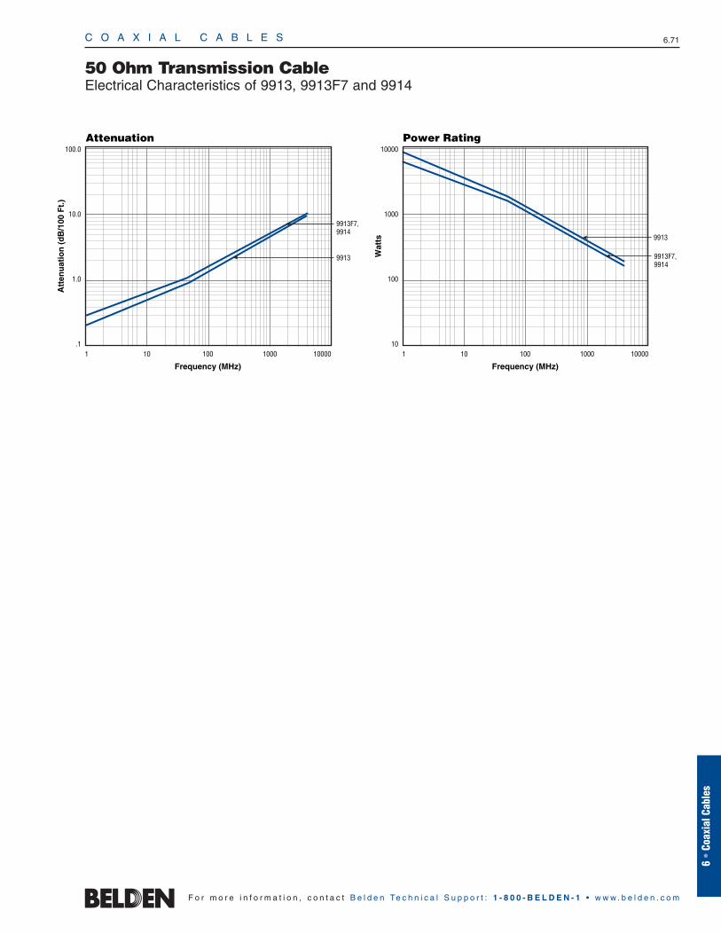
C O A X I A L C A B L E S 6.71
6 •
Coax
ial C
able
s
F o r m o r e i n f o r m a t i o n , c o n t a c t B e l d e n Te c h n i c a l S u p p o r t : 1 - 8 0 0 - B E L D E N - 1 • w w w . b e l d e n . c o m
50 Ohm Transmission CableElectrical Characteristics of 9913, 9913F7 and 9914
Frequency (MHz)
Attenuation
Att
enu
atio
n (
dB
/100
Ft.
)
100.0
10.0
1.0
.11 10 100 1000 10000
9913F7,9914
9913
Frequency (MHz)
Power Rating
Wat
ts
10000
1000
100
101 10 100 1000 10000
9913F7,9914
9913
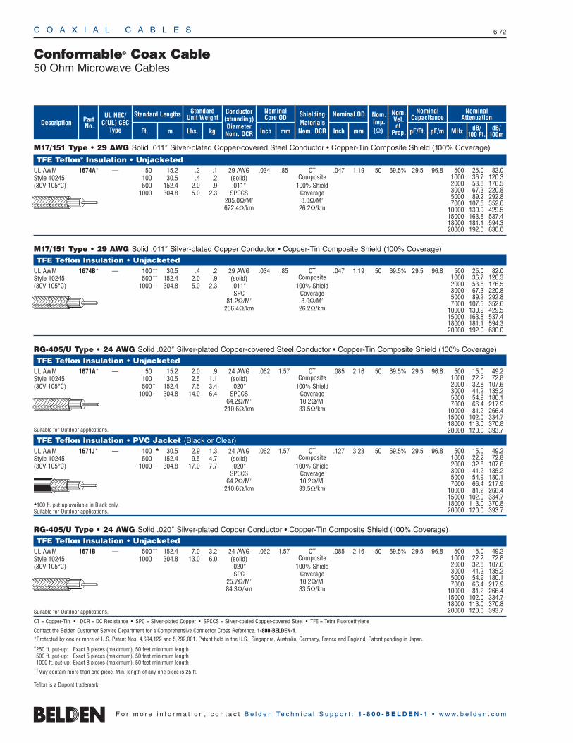
C O A X I A L C A B L E S 6.72
F o r m o r e i n f o r m a t i o n , c o n t a c t B e l d e n Te c h n i c a l S u p p o r t : 1 - 8 0 0 - B E L D E N - 1 • w w w . b e l d e n . c o m
M17/151 Type • 29 AWG Solid .011″ Silver-plated Copper-covered Steel Conductor • Copper-Tin Composite Shield (100% Coverage)
TFE Teflon® Insulation • UnjacketedUL AWM 1674A* — 50 15.2 .2 .1 29 AWG .034 .85 CT .047 1.19 50 69.5% 29.5 96.8Style 10245 100 30.5 .4 .2 (solid) Composite(30V 105°C) 500 152.4 2.0 .9 .011″ 100% Shield
1000 304.8 5.0 2.3 SPCCS Coverage205.0Ω/M′ 8.0Ω/M′672.4Ω/km 26.2Ω/km
M17/151 Type • 29 AWG Solid .011″ Silver-plated Copper Conductor • Copper-Tin Composite Shield (100% Coverage)
TFE Teflon Insulation • UnjacketedUL AWM 1674B* — 100 †† 30.5 .4 .2 29 AWG .034 .85 CT .047 1.19 50 69.5% 29.5 96.8Style 10245 500 †† 152.4 2.0 .9 (solid) Composite(30V 105°C) 1000 †† 304.8 5.0 2.3 .011″ 100% Shield
SPC Coverage81.2Ω/M′ 8.0Ω/M′
266.4Ω/km 26.2Ω/km
RG-405/U Type • 24 AWG Solid .020″ Silver-plated Copper-covered Steel Conductor • Copper-Tin Composite Shield (100% Coverage)
TFE Teflon Insulation • UnjacketedUL AWM 1671A* — 50 15.2 2.0 .9 24 AWG .062 1.57 CT .085 2.16 50 69.5% 29.5 96.8Style 10245 100 30.5 2.5 1.1 (solid) Composite(30V 105°C) 500 † 152.4 7.5 3.4 .020″ 100% Shield
1000 † 304.8 14.0 6.4 SPCCS Coverage64.2Ω/M′ 10.2Ω/M′
210.6Ω/km 33.5Ω/km
Suitable for Outdoor applications.
TFE Teflon Insulation • PVC Jacket (Black or Clear)UL AWM 1671J* — 100 † 30.5 2.9 1.3 24 AWG .062 1.57 CT .127 3.23 50 69.5% 29.5 96.8Style 10245 500 † 152.4 9.5 4.7 (solid) Composite(30V 105°C) 1000 † 304.8 17.0 7.7 .020″ 100% Shield
SPCCS Coverage64.2Ω/M′ 10.2Ω/M′
210.6Ω/km 33.5Ω/km
100 ft. put-up available in Black only.Suitable for Outdoor applications.
RG-405/U Type • 24 AWG Solid .020″ Silver-plated Copper Conductor • Copper-Tin Composite Shield (100% Coverage)
TFE Teflon Insulation • Unjacketed UL AWM 1671B — 500 †† 152.4 7.0 3.2 24 AWG .062 1.57 CT .085 2.16 50 69.5% 29.5 96.8Style 10245 1000 †† 304.8 13.0 6.0 (solid) Composite(30V 105°C) .020″ 100% Shield
SPC Coverage25.7Ω/M′ 10.2Ω/M′84.3Ω/km 33.5Ω/km
Suitable for Outdoor applications.
CT = Copper-Tin • DCR = DC Resistance • SPC = Silver-plated Copper • SPCCS = Silver-coated Copper-covered Steel • TFE = Tetra Fluoroethylene
Contact the Belden Customer Service Department for a Comprehensive Connector Cross Reference. 1-800-BELDEN-1.*Protected by one or more of U.S. Patent Nos. 4,694,122 and 5,292,001. Patent held in the U.S., Singapore, Australia, Germany, France and England. Patent pending in Japan.†250 ft. put-up: Exact 3 pieces (maximum), 50 feet minimum length500 ft. put-up: Exact 5 pieces (maximum), 50 feet minimum length1000 ft. put-up: Exact 8 pieces (maximum), 50 feet minimum length
††May contain more than one piece. Min. length of any one piece is 25 ft.
Conformable® Coax Cable50 Ohm Microwave Cables
500 25.0 82.01000 36.7 120.32000 53.8 176.53000 67.3 220.85000 89.2 292.87000 107.5 352.6
10000 130.9 429.515000 163.8 537.418000 181.1 594.320000 192.0 630.0
500 25.0 82.01000 36.7 120.32000 53.8 176.53000 67.3 220.85000 89.2 292.87000 107.5 352.6
10000 130.9 429.515000 163.8 537.418000 181.1 594.320000 192.0 630.0
500 15.0 49.21000 22.2 72.82000 32.8 107.63000 41.2 135.25000 54.9 180.17000 66.4 217.9
10000 81.2 266.415000 102.0 334.718000 113.0 370.820000 120.0 393.7
500 15.0 49.21000 22.2 72.82000 32.8 107.63000 41.2 135.25000 54.9 180.17000 66.4 217.9
10000 81.2 266.415000 102.0 334.718000 113.0 370.820000 120.0 393.7
500 15.0 49.21000 22.2 72.82000 32.8 107.63000 41.2 135.25000 54.9 180.17000 66.4 217.9
10000 81.2 266.415000 102.0 334.718000 113.0 370.820000 120.0 393.7
Teflon is a Dupont trademark.
ShieldingMaterialsNom. DCR
Nom.Imp.(Ω)
Nominal Core OD Nominal OD
Inch mm Inch mm
Conductor(stranding)DiameterNom. DCR
StandardUnit WeightStandard Lengths
Lbs. kgFt. m
UL NEC/C(UL) CEC
Type
PartNo.
MHz dB/100 Ft.
dB/100m
Nominal Attenuation
Nominal Capacitance
pF/mpF/Ft.
Nom.Vel.of
Prop.Description

RG-402/U Type • 19 AWG Solid .036″ Silver-plated Copper-covered Steel Conductor • Copper-Tin Composite Shield (100% Coverage)
TFE Teflon® Insulation • UnjacketedUL AWM 1673A* — 50 15.2 3.3 1.5 19 AWG .116 2.95 CT .138 3.51 50 69.5% 29.5 96.8Style 10245 100 30.5 3.9 1.8 (solid) Composite(30V 105°C) 250 † 76.2 8.0 3.6 .036″ 100% Shield
500 152.4 15.0 6.8 SPCCS Coverage20.5Ω/M′ 4.5Ω/M′67.3Ω/km 14.8Ω/km
TFE Teflon Insulation • Black PVC JacketUL AWM 1673J* — 100 30.5 5.1 2.3 19 AWG .116 2.95 CT .178 4.52 50 69.5% 29.5 96.8Style 10245 500 † 152.4 17.5 8.0 (solid) Composite(30V 105°C) .036″ 100% Shield
SPCCS Coverage20.5Ω/M′ 4.5Ω/M′67.3Ω/km 14.8Ω/km
RG-402/U Type • 19 AWG Solid .036″ Silver-plated Copper Conductor • Copper-Tin Composite Shield (100% Coverage)
TFE Teflon Insulation • UnjacketedUL AWM 1673B* — 100 †† 30.5 3.9 1.8 19 AWG .116 2.95 CT .138 3.51 50 69.5% 29.5 96.8Style 10245 250 †† 76.2 8.0 3.6 (solid) Composite(30V 105°C) 500 †† 152.4 14.5 6.6 .036″ 100% Shield
SPC Coverage7.9Ω/M′ 4.5Ω/M′
25.9Ω/km 14.8Ω/km
RG-401/U Type •14 AWG Solid .065″ Silver-plated Copper Conductor • Copper-Tin Composite Shield (100% Coverage)
TFE Teflon Insulation • UnjacketedUL AWM 1675A* — 50 † 15.2 4.1 1.8 14 AWG .210 5.33 CT .246 6.25 50 69.5% 29.6 97.1Style 10245 100 †† 30.5 8.1 3.7 (solid) Composite(30V 105°C) 250 †† 76.2 20.3 9.2 .065″ 100% Shield
500 †† 152.4 40.5 18.4 SPC Coverage2.5Ω/M′ 8.0Ω/M′8.2Ω/km 26.2Ω/km
CT = Copper-Tin • DCR = DC Resistance • SPCCS = Silver-plated Copper-covered Steel • SPC = Silver-plated Copper • TFE = Tetra Fluoroethylene
Contact the Belden Customer Service Department for a Comprehensive Connector Cross Reference. 1-800-BELDEN-1.
* Protected by one or more of U.S. Patent Nos. 4,694,122 and 5,292,001. Patent held in the U.S., Singapore, Australia, Germany, France and England. Patent pending in Japan.† 250 ft. put-up: Exact 3 pieces (maximum), 50 feet minimum length
500 ft. put-up: Exact 5 pieces (maximum), 50 feet minimum length1000 ft. put-up: Exact 8 pieces (maximum), 50 feet minimum length
††May contain more than one piece, minimum length of any one piece is 25 ft.
C O A X I A L C A B L E S 6.73
6 •
Coax
ial C
able
s
F o r m o r e i n f o r m a t i o n , c o n t a c t B e l d e n Te c h n i c a l S u p p o r t : 1 - 8 0 0 - B E L D E N - 1 • w w w . b e l d e n . c o m
500 8.0 26.21000 12.0 39.42000 18.1 59.43000 22.9 75.15000 31.0 101.77000 37.8 124.0
10000 46.6 152.915000 59.1 193.918000 65.8 215.920000 70.0 229.7
500 8.0 26.21000 12.0 39.42000 18.1 59.43000 22.9 75.15000 31.0 101.77000 37.8 124.0
10000 46.6 152.915000 59.1 193.918000 65.8 215.920000 70.0 229.7
500 8.0 26.21000 12.0 39.42000 18.1 59.43000 22.9 75.15000 31.0 101.77000 37.8 124.0
10000 46.6 152.915000 59.1 193.918000 65.8 215.920000 70.0 229.7
400 3.8 12.5500 4.4 14.4
1000 6.8 22.32000 10.4 34.13000 13.4 44.05000 18.5 60.77000 22.8 74.8
10000 28.4 93.215000 36.6 120.118000 41.0 134.5
Conformable® Coax Cable50 Ohm Microwave Cables
Teflon is a DuPont trademark.
ShieldingMaterialsNom. DCR
Nom.Imp.(Ω)
Nominal Core OD Nominal OD
Inch mm Inch mm
Conductor(stranding)DiameterNom. DCR
StandardUnit WeightStandard Lengths
Lbs. kgFt. m
UL NEC/C(UL) CEC
Type
PartNo.
MHz dB/100 Ft.
dB/100m
Nominal Attenuation
Nominal Capacitance
pF/mpF/Ft.
Nom.Vel.of
Prop.Description
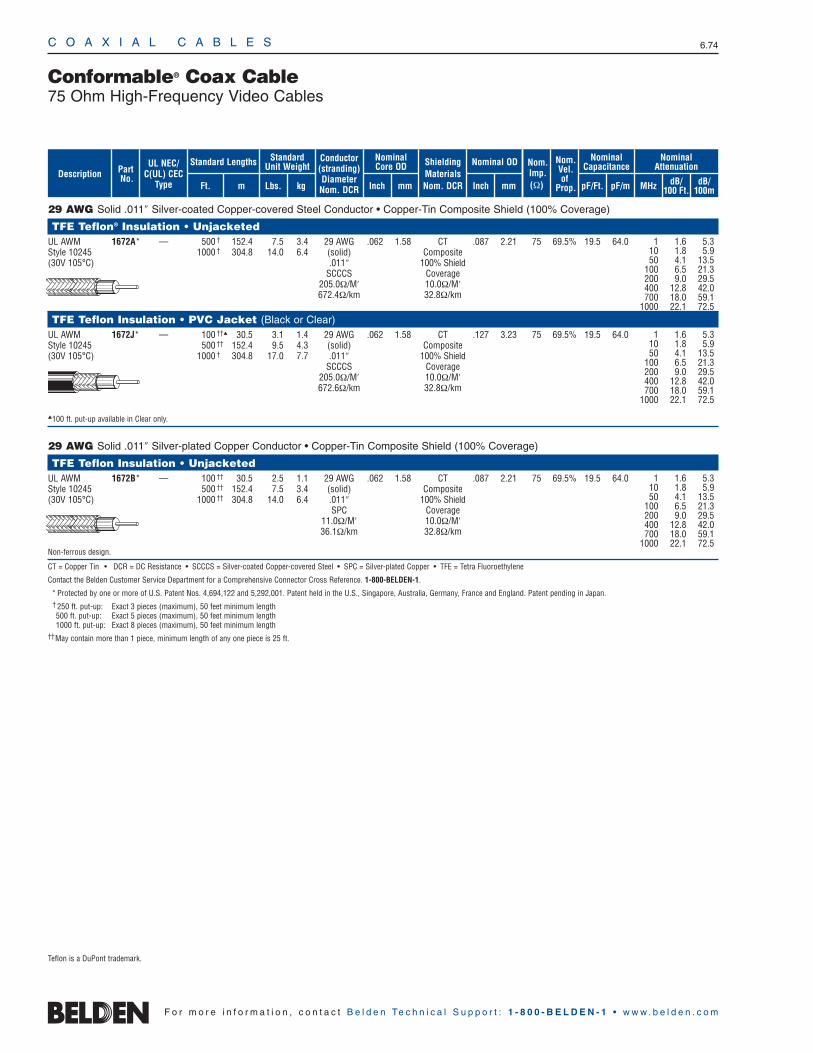
C O A X I A L C A B L E S 6.74
F o r m o r e i n f o r m a t i o n , c o n t a c t B e l d e n Te c h n i c a l S u p p o r t : 1 - 8 0 0 - B E L D E N - 1 • w w w . b e l d e n . c o m
29 AWG Solid .011″ Silver-coated Copper-covered Steel Conductor • Copper-Tin Composite Shield (100% Coverage)
TFE Teflon® Insulation • UnjacketedUL AWM 1672A* — 500 † 152.4 7.5 3.4 29 AWG .062 1.58 CT .087 2.21 75 69.5% 19.5 64.0Style 10245 1000 † 304.8 14.0 6.4 (solid) Composite(30V 105°C) .011″ 100% Shield
SCCCS Coverage205.0Ω/M′ 10.0Ω/M′672.4Ω/km 32.8Ω/km
TFE Teflon Insulation • PVC Jacket (Black or Clear)UL AWM 1672J* — 100 †† 30.5 3.1 1.4 29 AWG .062 1.58 CT .127 3.23 75 69.5% 19.5 64.0Style 10245 500 †† 152.4 9.5 4.3 (solid) Composite(30V 105°C) 1000 † 304.8 17.0 7.7 .011″ 100% Shield
SCCCS Coverage205.0Ω/M′ 10.0Ω/M′672.6Ω/km 32.8Ω/km
100 ft. put-up available in Clear only.
29 AWG Solid .011″ Silver-plated Copper Conductor • Copper-Tin Composite Shield (100% Coverage)
TFE Teflon Insulation • UnjacketedUL AWM 1672B* — 100 †† 30.5 2.5 1.1 29 AWG .062 1.58 CT .087 2.21 75 69.5% 19.5 64.0Style 10245 500 †† 152.4 7.5 3.4 (solid) Composite(30V 105°C) 1000 †† 304.8 14.0 6.4 .011″ 100% Shield
SPC Coverage11.0Ω/M′ 10.0Ω/M′36.1Ω/km 32.8Ω/km
Non-ferrous design.
CT = Copper Tin • DCR = DC Resistance • SCCCS = Silver-coated Copper-covered Steel • SPC = Silver-plated Copper • TFE = Tetra Fluoroethylene
Contact the Belden Customer Service Department for a Comprehensive Connector Cross Reference. 1-800-BELDEN-1.
* Protected by one or more of U.S. Patent Nos. 4,694,122 and 5,292,001. Patent held in the U.S., Singapore, Australia, Germany, France and England. Patent pending in Japan.† 250 ft. put-up: Exact 3 pieces (maximum), 50 feet minimum length500 ft. put-up: Exact 5 pieces (maximum), 50 feet minimum length1000 ft. put-up: Exact 8 pieces (maximum), 50 feet minimum length
††May contain more than 1 piece, minimum length of any one piece is 25 ft.
Conformable® Coax Cable75 Ohm High-Frequency Video Cables
1 1.6 5.310 1.8 5.950 4.1 13.5
100 6.5 21.3200 9.0 29.5400 12.8 42.0700 18.0 59.1
1000 22.1 72.5
1 1.6 5.310 1.8 5.950 4.1 13.5
100 6.5 21.3200 9.0 29.5400 12.8 42.0700 18.0 59.1
1000 22.1 72.5
1 1.6 5.310 1.8 5.950 4.1 13.5
100 6.5 21.3200 9.0 29.5400 12.8 42.0700 18.0 59.1
1000 22.1 72.5
Teflon is a DuPont trademark.
ShieldingMaterialsNom. DCR
Nom.Imp.(Ω)
Nominal Core OD Nominal OD
Inch mm Inch mm
Conductor(stranding)DiameterNom. DCR
StandardUnit WeightStandard Lengths
Lbs. kgFt. m
UL NEC/C(UL) CEC
Type
PartNo.
MHz dB/100 Ft.
dB/100m
Nominal Attenuation
Nominal Capacitance
pF/mpF/Ft.
Nom.Vel.of
Prop.Description
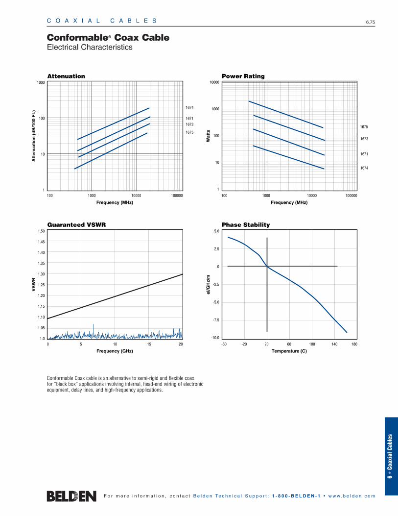
C O A X I A L C A B L E S 6.75
6 •
Coax
ial C
able
s
F o r m o r e i n f o r m a t i o n , c o n t a c t B e l d e n Te c h n i c a l S u p p o r t : 1 - 8 0 0 - B E L D E N - 1 • w w w . b e l d e n . c o m
Conformable® Coax CableElectrical Characteristics
Conformable Coax cable is an alternative to semi-rigid and flexible coax for “black box” applications involving internal, head-end wiring of electronicequipment, delay lines, and high-frequency applications.
Frequency (MHz)
Attenuation
Att
enu
atio
n (
dB
/100
Ft.
)
1000
100
10
1100 1000 10000 100000
1674
16711673
1675
Frequency (MHz)
Power Rating
Wat
ts
10000
1000
100
10
1
100 1000 10000 100000
1673
1671
1674
1675
Frequency (GHz)
Guaranteed VSWR
VS
WR
1.50
1.45
1.40
1.35
1.30
1.25
1.20
1.15
1.10
1.05
1.00 5 10 15 20
Temperature (C)
Phase Stability
el/G
Hz/
m
5.0
2.5
0
-2.5
-5.0
-7.5
-10.0
-60 -20 20 60 100 140 180

C O A X I A L C A B L E S 6.76
F o r m o r e i n f o r m a t i o n , c o n t a c t B e l d e n Te c h n i c a l S u p p o r t : 1 - 8 0 0 - B E L D E N - 1 • w w w . b e l d e n . c o m
30 AWG Stranded (7x38) .012″ Silver-plated Copper-covered Steel Conductor • Silver-plated Copper Braid Shield (96% Coverage)
TFE Teflon® Insulation • White FEP Jacket200°C 83265 — 100 † 30.5 .8 .4 30 AWG .033 .84 SPC Braid .071 1.80 50 69.5% 29.0 95.1VW-1 500 † 152.4 4.0 1.6 (7x38) 96% Shield
1000 † 304.8 6.0 3.2 .012″ CoverageSPCCS 14.6Ω/M′
244.0Ω/M′ 47.9Ω/km801.0Ω/km
M17/169-00001 (RG-178B/U). Non-SWR swept version of RG-178.
26 AWG Stranded (7x34) .020″ Silver-plated Copper-covered Steel Conductor • Silver-plated Copper Braid Shield (95% Coverage)
TFE Teflon Insulation • White FEP Jacket200°C 83284 — 100 † 30.5 1.2 .5 26 AWG .058 1.47 SPC Braid .098 2.49 50 69.5% 29.0 95.1VW-1 500 † 152.4 5.5 2.7 (7x34) 95% Shield
1000 † 304.8 11.0 5.0 .020″ CoverageSPCCS 6.5Ω/M′
84.1Ω/M′ 21.3Ω/km275.9Ω/km
M17/172-00001 (RG-316/U). Non-SWR swept version of RG-316.
TFE Teflon Insulation • Brown FEP Jacket200°C 84316 — 100 † 30.5 1.2 .5 26 AWG .058 1.47 SPC Braid .098 2.49 50 69.5% 29.0 95.1VW-1 500 † 152.4 5.5 2.5 (7x34) 95% Shield
1000 † 304.8 11.0 5.0 .020″ CoverageSPCCS 6.5Ω/M′
84.1Ω/M′ 21.3Ω/km275.9Ω/km
M17/113-RG316
22 AWG Stranded (27x36) .030″ Tinned Copper Conductor • Tinned Copper Braid Shield (95% Coverage)
Polyethylene Insulation • Black Non-contaminating PVC JacketUL AWM 9252 NEC: 1000 304.8 18.0 8.2 22 AWG .096 2.44 TC Braid .160 4.06 50 66% 30.8 101.0Style 1354 CMX (27x36) Shield(30V 80°C) CEC: .030″ 95% ShieldVW-1 CMX TC Coverage
17.1Ω/M′ 5.2Ω/M′56.1Ω/km 17.1Ω/km
M17/157-00001 (RG-122/U). Non-SWR swept version of RG-122.
DCR = DC Resistance • FEP = Fluorinated Ethylene Propylene • SPC = Silver-plated Copper • SPCCS = Silver-plated Copper-covered Steel • TC = Tinned Copper • TFE = Tetra Fluoroethylene
Contact the Belden Customer Service Department for a Comprehensive Connector Cross Reference. 1-800-BELDEN-1. †May contain more than one piece, minimum length of any one piece is 25 ft.
MIL-C-17G QPL Cable50 Ohm Coax
1 2.6 8.510 5.6 18.450 10.5 34.5
100 14.0 45.9200 19.0 62.3400 28.0 91.9700 37.0 121.4900 42.5 139.4
1000 46.0 150.9
1 1.2 3.910 2.7 8.950 5.6 18.4
100 8.3 27.2200 12.0 39.4400 17.5 57.4700 23.7 77.8900 27.3 89.6
1000 29.0 95.1
1 1.2 3.910 2.7 8.950 5.6 18.4
100 8.3 27.2200 12.0 39.4400 17.5 57.4700 23.7 77.8900 27.3 89.6
1000 29.0 95.1
1 .4 1.310 1.7 5.650 4.5 14.8
100 7.0 23.0200 11.0 36.1400 16.5 54.1700 23.5 77.1900 27.3 89.6
1000 29.0 95.1
Teflon is a DuPont trademark.
ShieldingMaterialsNom. DCR
Nom.Imp.(Ω)
Nominal Core OD Nominal OD
Inch mm Inch mm
Conductor(stranding)DiameterNom. DCR
StandardUnit WeightStandard Lengths
Lbs. kgFt. m
UL NEC/C(UL) CEC
Type
PartNo.
MHz dB/100 Ft.
dB/100m
Nominal Attenuation
Nominal Capacitance
pF/mpF/Ft.
Nom.Vel.of
Prop.Description
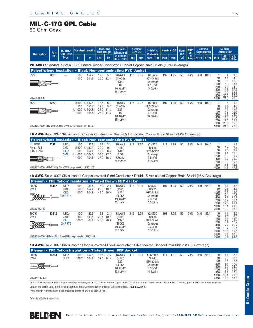
C O A X I A L C A B L E S 6.77
6 •
Coax
ial C
able
s
F o r m o r e i n f o r m a t i o n , c o n t a c t B e l d e n Te c h n i c a l S u p p o r t : 1 - 8 0 0 - B E L D E N - 1 • w w w . b e l d e n . c o m
20 AWG Stranded (19x33) .035″ Tinned Copper Conductor • Tinned Copper Braid Shield (95% Coverage)
Polyethylene Insulation • Black Non-contaminating PVC Jacket85°C 9203 — 500 152.4 12.5 5.7 20 AWG .116 2.95 TC Braid .195 4.95 50 66% 30.8 101.0
1000 304.8 25.0 12.3 (19x33) 95% Shield.035″ Coverage
TC 4.1Ω/M′10.8Ω/M′ 13.5Ω/km35.4Ω/km
M17/28-RG58
85°C 8262 — U-500 U-152.4 13.5 6.1 20 AWG .115 2.92 TC Braid .195 4.95 50 66% 30.8 101.0500 152.4 12.5 5.7 (19x33) 95% Shield
U-1000 U-304.8 26.0 11.8 .035″ Coverage1000 304.8 25.0 11.3 TC 4.1Ω/M′
10.8Ω/M′ 13.5Ω/km35.4Ω/km
M17/155-00001 (RG-58C/U). Non-SWR swept version of RG-58.
19 AWG Solid .034″ Silver-coated Copper Conductor • Double Silver-coated Copper Braid Shield (95% Coverage)
Polyethylene Insulation • Black Non-contaminating PVC JacketUL AWM 9273 NEC: 100 30.5 4.7 2.1 19 AWG .117 2.97 (2) SCC .212 5.39 50 66% 30.8 101.0Style 1354 CMX U-500 U-152.4 20.0 9.1 (solid) Braids(30V 60°C) CEC: 500 152.4 18.5 8.4 .034″ 95% Shield
CMX U-1000 U-304.8 39.0 17.7 SCC Coverage1000 304.8 37.0 16.8 8.8Ω/M′ 2.5Ω/M′
28.9Ω/km 8.2Ω/km
M17/167-00001 (RG-223/U). Non-SWR swept version of RG-223.
18 AWG Solid .037″ Silver-coated Copper-covered Steel Conductor • Double Silver-coated Copper Braid Shield (96% Coverage)
Plenum • TFE Teflon® Insulation • Tinted Brown FEP Jacket200°C 84142 NEC: 100 30.5 5.0 2.3 18 AWG .116 2.95 (2) SCC .195 4.95 50 70% 29.0 95.1VW-1 CMP 500 † 152.4 22.5 10.2 (solid) Braids
CEC: 1000 † 304.8 46.0 20.9 .037″ 96% ShieldCMP FT6 SCCCS Coverage
19.3Ω/M′ 2.3Ω/M′63.3Ω/km 7.5Ω/km
M17/60-RG142
200°C 83242 NEC: 100 † 30.5 5.3 2.4 18 AWG .116 2.95 (2) SCC .195 4.95 50 70% 29.0 95.1VW-1 CMP 500 † 152.4 22.5 10.2 (solid) Braids
CEC: 1000 † 304.8 46.0 20.9 .037″ 96% ShieldCMP FT6 SCCCS Coverage
19.3Ω/M′ 2.3Ω/M′63.3Ω/km 7.5Ω/km
M17/158-00001 (RG-142B/U). Non-SWR swept version of RG-142.
18 AWG Solid .037″ Silver-coated Copper-covered Steel Conductor • Silver-coated Copper Braid Shield (95% Coverage)
Plenum • TFE Teflon Insulation • Tinted Brown FEP Jacket200°C 84303 NEC: 500 † 152.4 16.5 7.5 18 AWG .116 2.95 SCC Braid .170 4.31 50 70% 29.0 95.1VW-1 CL2P 1000 † 304.8 32.0 14.5 (solid) Shield
.037″ 95% ShieldSCCCS Coverage
16.3Ω/M′ 4.3Ω/M′53.5Ω/km 14.1Ω/km
M17/111-RG303
DCR = DC Resistance • FEP = Fluorinated Ethylene Propylene • SCC = Silver-coated Copper • SCCCS = Silver-coated Copper-covered Steel • TC = Tinned Copper • TFE = Tetra Fluoroethylene
Contact the Belden Customer Service Department for a Comprehensive Connector Cross Reference. 1-800-BELDEN-1.†May contain more than one piece, minimum length of any 1 piece is 25 feet.
MIL-C-17G QPL Cable50 Ohm Coax
1 .4 1.310 1.4 4.650 3.3 10.8
100 4.9 16.1200 7.3 24.0400 11.5 37.7700 17.0 55.8900 20.0 65.6
1000 21.5 70.5
1 .4 1.310 1.4 4.650 3.3 10.8
100 4.9 16.1200 7.3 24.0400 11.5 37.7700 17.0 55.8900 20.0 65.6
1000 21.5 70.5
1 .4 1.310 1.2 3.950 2.8 9.2
100 4.1 13.5200 6.0 19.7400 8.8 28.9700 12.0 39.4900 13.8 45.3
1000 14.5 47.6
10 1.1 3.650 2.6 8.5
100 3.8 12.5200 5.4 17.7400 7.9 25.9700 10.7 35.1900 12.3 40.4
1000 13.1 43.02000 19.3 63.3
10 1.1 3.650 2.6 8.5
100 3.8 12.5200 5.4 17.7400 7.9 25.9700 10.7 35.1900 12.3 40.4
1000 13.1 43.02000 19.3 63.3
10 1.1 3.650 2.6 8.5
100 3.8 12.5200 5.4 17.7400 7.9 25.9700 10.7 35.1900 12.3 40.4
1000 13.1 43.02000 19.3 63.3
Teflon is a DuPont trademark.
ShieldingMaterialsNom. DCR
Nom.Imp.(Ω)
Nominal Core OD Nominal OD
Inch mm Inch mm
Conductor(stranding)DiameterNom. DCR
StandardUnit WeightStandard Lengths
Lbs. kgFt. m
UL NEC/C(UL) CEC
Type
PartNo.
MHz dB/100 Ft.
dB/100m
Nominal Attenuation
Nominal Capacitance
pF/mpF/Ft.
Nom.Vel.of
Prop.Description
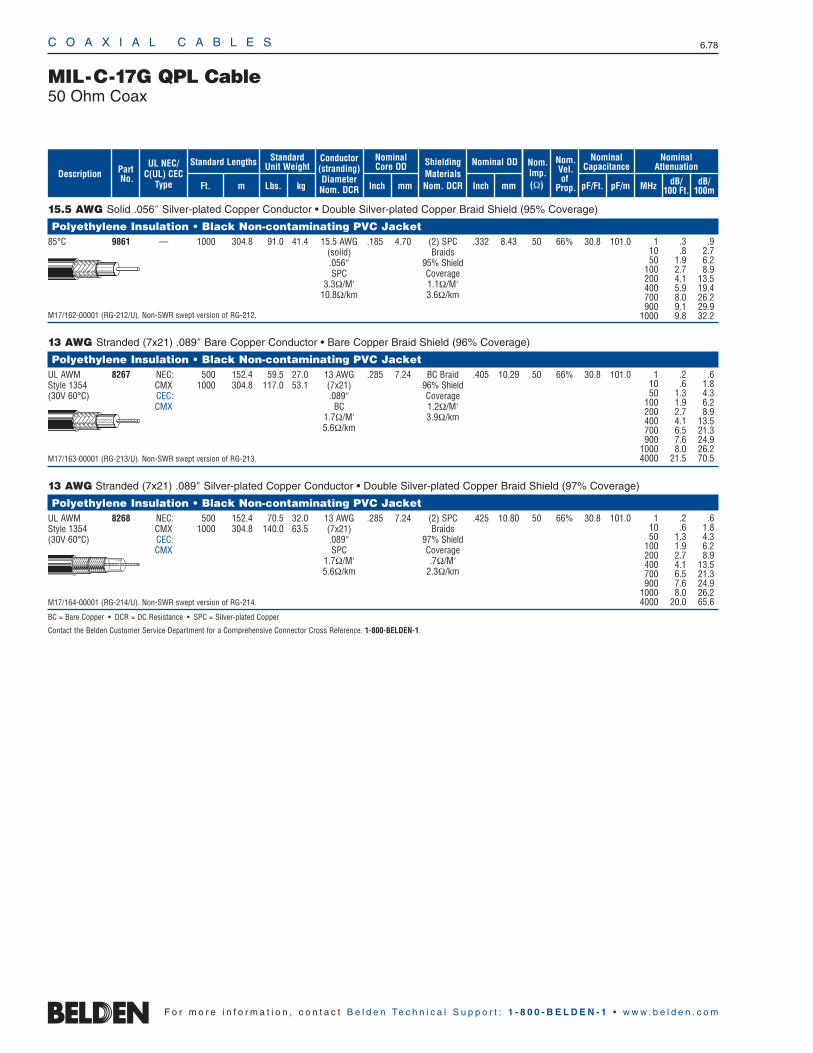
C O A X I A L C A B L E S 6.78
F o r m o r e i n f o r m a t i o n , c o n t a c t B e l d e n Te c h n i c a l S u p p o r t : 1 - 8 0 0 - B E L D E N - 1 • w w w . b e l d e n . c o m
15.5 AWG Solid .056″ Silver-plated Copper Conductor • Double Silver-plated Copper Braid Shield (95% Coverage)
Polyethylene Insulation • Black Non-contaminating PVC Jacket85°C 9861 — 1000 304.8 91.0 41.4 15.5 AWG .185 4.70 (2) SPC .332 8.43 50 66% 30.8 101.0
(solid) Braids.056″ 95% ShieldSPC Coverage
3.3Ω/M′ 1.1Ω/M′10.8Ω/km 3.6Ω/km
M17/162-00001 (RG-212/U). Non-SWR swept version of RG-212.
13 AWG Stranded (7x21) .089″ Bare Copper Conductor • Bare Copper Braid Shield (96% Coverage)
Polyethylene Insulation • Black Non-contaminating PVC JacketUL AWM 8267 NEC: 500 152.4 59.5 27.0 13 AWG .285 7.24 BC Braid .405 10.29 50 66% 30.8 101.0Style 1354 CMX 1000 304.8 117.0 53.1 (7x21) 96% Shield(30V 60°C) CEC: .089″ Coverage
CMX BC 1.2Ω/M′1.7Ω/M′ 3.9Ω/km5.6Ω/km
M17/163-00001 (RG-213/U). Non-SWR swept version of RG-213.
13 AWG Stranded (7x21) .089″ Silver-plated Copper Conductor • Double Silver-plated Copper Braid Shield (97% Coverage)
Polyethylene Insulation • Black Non-contaminating PVC JacketUL AWM 8268 NEC: 500 152.4 70.5 32.0 13 AWG .285 7.24 (2) SPC .425 10.80 50 66% 30.8 101.0Style 1354 CMX 1000 304.8 140.0 63.5 (7x21) Braids(30V 60°C) CEC: .089″ 97% Shield
CMX SPC Coverage1.7Ω/M′ .7Ω/M′5.6Ω/km 2.3Ω/km
M17/164-00001 (RG-214/U). Non-SWR swept version of RG-214.
BC = Bare Copper • DCR = DC Resistance • SPC = Silver-plated Copper
Contact the Belden Customer Service Department for a Comprehensive Connector Cross Reference. 1-800-BELDEN-1.
MIL-C-17G QPL Cable50 Ohm Coax
1 .3 .910 .8 2.750 1.9 6.2
100 2.7 8.9200 4.1 13.5400 5.9 19.4700 8.0 26.2900 9.1 29.9
1000 9.8 32.2
1 .2 .610 .6 1.850 1.3 4.3
100 1.9 6.2200 2.7 8.9400 4.1 13.5700 6.5 21.3900 7.6 24.9
1000 8.0 26.24000 21.5 70.5
1 .2 .610 .6 1.850 1.3 4.3
100 1.9 6.2200 2.7 8.9400 4.1 13.5700 6.5 21.3900 7.6 24.9
1000 8.0 26.24000 20.0 65.6
ShieldingMaterialsNom. DCR
Nom.Imp.(Ω)
Nominal Core OD Nominal OD
Inch mm Inch mm
Conductor(stranding)DiameterNom. DCR
StandardUnit WeightStandard Lengths
Lbs. kgFt. m
UL NEC/C(UL) CEC
Type
PartNo.
MHz dB/100 Ft.
dB/100m
Nominal Attenuation
Nominal Capacitance
pF/mpF/Ft.
Nom.Vel.of
Prop.Description
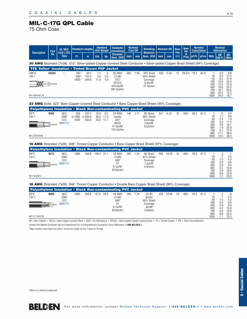
30 AWG Stranded (7x38) .012″ Silver-plated Copper-covered Steel Conductor • Silver-plated Copper Braid Shield (94% Coverage)
TFE Teflon® Insulation • Tinted Brown FEP Jacket200°C 83264 — 100 † 30.5 1.2 .5 30 AWG .062 1.58 SPC Braid .100 2.54 75 69.5% 19.5 64.0VW-1 500 † 152.4 5.5 2.5 (7x38) 94% Shield
1000 † 304.8 11.0 5.0 .012″ CoverageSPCCS 8.5Ω/M′
244.0Ω/M′ 27.4Ω/km801.0Ω/km
M17/94-RG179
23 AWG Solid .023″ Bare Copper-covered Steel Conductor • Bare Copper Braid Shield (95% Coverage)
Polyethylene Insulation • Black Non-contaminating PVC Jacket60°C 9204 NEC: 500 152.4 18.0 8.2 23 AWG .146 3.71 BC Braid .241 6.12 75 66% 20.5 67.3VW-1 CMH U-1000 U-304.8 38.0 17.3 (solid) 95% Shield
CEC: 1000 304.8 39.0 17.7 .023″ CoverageCMH FT1 BCCS 2.6Ω/M′
47.0Ω/M′ 8.5Ω/km154.2Ω/km
M17/29-RG59
18 AWG Stranded (7x26) .048″ Tinned Copper Conductor • Bare Copper Braid Shield (97% Coverage)
Polyethylene Insulation • Black Non-contaminating PVC Jacket60°C 9212 NEC: 1000 304.8 105.0 47.7 18 AWG .285 7.24 BC Braid .405 10.29 75 66% 20.5 67.3VW-1 CMH (7x26) 97% Shield
CEC: .048″ CoverageCMH FT1 TC 1.2Ω/M′
6.1Ω/M′ 3.9Ω/km20.0Ω/km
M17/6-RG11
18 AWG Stranded (7x26) .048″ Tinned Copper Conductor • Double Bare Copper Braid Shield (95% Coverage)
Polyethylene Insulation • Black Non-contaminating PVC Jacket60°C 9850 NEC: 1000 304.8 131.0 59.5 18 AWG .285 7.24 (2) BC .425 10.80 75 66% 20.5 67.3VW-1 CMH (7x26) Braids
CEC: .048″ 95% ShieldCMH FT1 TC Coverage
6.1Ω/M′ .8Ω/M′20.0Ω/km 2.6Ω/km
M17/77-RG216
BC = Bare Copper • BCCS = Bare Copper-covered Steel • DCR = DC Resistance • SPCCS = Silver-plated Copper-covered Steel • TC = Tinned Copper • TFE = Tetra Fluoroethylene
Contact the Belden Customer Service Department for a Comprehensive Connector Cross Reference. 1-800-BELDEN-1. †May contain more than one piece, minimum length of any 1 piece is 25 feet.
C O A X I A L C A B L E S 6.79
6 •
Coax
ial C
able
s
F o r m o r e i n f o r m a t i o n , c o n t a c t B e l d e n Te c h n i c a l S u p p o r t : 1 - 8 0 0 - B E L D E N - 1 • w w w . b e l d e n . c o m
MIL-C-17G QPL Cable75 Ohm Coax
1 .6 2.010 1.1 3.650 2.4 7.9
100 3.4 11.2200 4.9 16.1400 7.0 23.0700 9.7 31.8900 11.1 36.4
1000 12.0 39.4
1 .2 .710 .7 2.350 1.3 4.3
100 2.0 6.6200 2.9 9.5400 4.2 13.8700 5.8 19.0900 6.9 22.6
1000 7.2 23.6
1 .2 .610 .7 2.250 1.3 4.3
100 2.0 6.6200 2.9 9.5400 4.2 13.8700 5.8 19.0900 6.8 22.3
1000 7.1 23.3
1 3.0 9.810 5.3 17.450 8.5 27.9
100 10.0 32.8200 12.5 41.0400 16.0 52.5700 19.7 64.6900 22.3 73.2
1000 24.0 78.7
Teflon is a DuPont trademark.
ShieldingMaterialsNom. DCR
Nom.Imp.(Ω)
Nominal Core OD Nominal OD
Inch mm Inch mm
Conductor(stranding)DiameterNom. DCR
StandardUnit WeightStandard Lengths
Lbs. kgFt. m
UL NEC/C(UL) CEC
Type
PartNo.
MHz dB/100 Ft.
dB/100m
Nominal Attenuation
Nominal Capacitance
pF/mpF/Ft.
Nom.Vel.of
Prop.Description
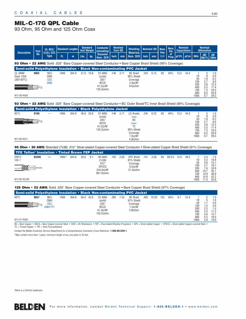
C O A X I A L C A B L E S 6.80
F o r m o r e i n f o r m a t i o n , c o n t a c t B e l d e n Te c h n i c a l S u p p o r t : 1 - 8 0 0 - B E L D E N - 1 • w w w . b e l d e n . c o m
93 Ohm • 22 AWG Solid .025″ Bare Copper-covered Steel Conductor • Bare Copper Braid Shield (95% Coverage)
Semi-solid Polyethylene Insulation • Black Non-contaminating PVC JacketUL AWM 9862 NEC: 1000 304.8 37.0 16.8 22 AWG .146 3.71 BC Braid .242 6.15 93 84% 13.5 44.3Style 1354 CMX (solid) 95% Shield(30V 60°C) CEC: .025″ Coverage
CMX BCCS 2.9Ω/M′41.2Ω/M′ 9.5Ω/km
135.2Ω/km
M17/30-RG62
93 Ohm • 22 AWG Solid .025″ Bare Copper-covered Steel Conductor • BC Outer Braid/TC Inner Braid Shield (95% Coverage)
Semi-solid Polyethylene Insulation • Black Polyethylene Jacket85°C 9169 — 1000 304.8 46.0 20.9 22 AWG .146 3.71 (2) Braids .245 6.22 93 84% 13.5 44.3
(solid) Inner:.025″ BCBCCS Outer:
41.2Ω/M′ TC135.2Ω/km 95% Shield
Coverage1.5Ω/M′
M17/90-RG71 4.9Ω/km
95 Ohm • 30 AWG Stranded (7x38) .012″ Silver-plated Copper-covered Steel Conductor • Silver-plated Copper Braid Shield (91% Coverage)
TFE Teflon® Insulation • Tinted Brown FEP Jacket200°C 83266 — 1000 † 304.8 20.0 9.1 30 AWG .102 2.60 SPC Braid .141 3.58 95 69.5% 15.0 49.2VW-1 (7x38) 91% Shield
.012″ CoverageSPCCS 6.5Ω/M′
244.0Ω/M′ 21.3Ω/km801.0Ω/km
M17/95-RG180
125 Ohm • 22 AWG Solid .025″ Bare Copper-covered Steel Conductor • Bare Copper Braid Shield (97% Coverage)
Semi-solid Polyethylene Insulation • Black Non-contaminating PVC Jacket60°C 9857 NEC: 1000 304.8 94.0 42.6 22 AWG .285 7.24 BC Braid .405 10.29 125 84% 9.7 31.8
CMH (solid) 97% ShieldCEC: .025″ Coverage
CMH FT1 BCCS 1.2Ω/M′41.2Ω/M′ 3.9Ω/km
135.2Ω/km
M17/31-RG63
BC = Bare Copper • BCCS = Bare Copper-covered Steel • DCR = DC Resistance • FEP = Fluorinated Ethylene Propylene • SPC = Silver-plated Copper • SPCCS = Silver-plated Copper-covered Steel •TC = Tinned Copper • TFE = Tetra Fluoroethylene
Contact the Belden Customer Service Department for a Comprehensive Connector Cross Reference. 1-800-BELDEN-1.†May contain more than 1 piece, minimum length of any one piece is 25 feet.
MIL-C-17G QPL Cable93 Ohm, 95 Ohm and 125 Ohm Coax
1 .3 1.010 .9 3.050 1.9 6.2
100 2.7 8.9200 3.8 12.5400 5.3 17.4700 7.3 24.0900 8.2 26.9
1000 8.7 28.5
1 .3 1.010 .9 3.050 1.9 6.2
100 2.7 8.9200 3.8 12.5400 5.3 17.4700 7.3 24.0900 8.2 26.9
1000 8.7 28.5
1 .2 1.010 .5 1.650 1.1 3.6
100 1.5 4.9200 2.3 7.5400 3.4 11.2700 4.6 15.1900 5.5 18.0
1000 5.8 19.0
1 2.4 7.910 3.3 10.850 4.6 15.1
100 5.7 18.7200 7.6 24.9400 10.7 35.1700 14.9 48.9900 15.9 52.2
1000 17.0 55.8
Teflon is a DuPont trademark.
ShieldingMaterialsNom. DCR
Nom.Imp.(Ω)
Nominal Core OD Nominal OD
Inch mm Inch mm
Conductor(stranding)DiameterNom. DCR
StandardUnit WeightStandard Lengths
Lbs. kgFt. m
UL NEC/C(UL) CEC
Type
PartNo.
MHz dB/100 Ft.
dB/100m
Nominal Attenuation
Nominal Capacitance
pF/mpF/Ft.
Nom.Vel.of
Prop.Description
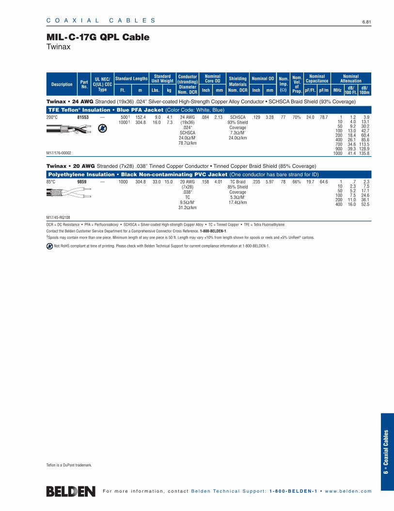
Twinax • 24 AWG Stranded (19x36) .024″ Silver-coated High-Strength Copper Alloy Conductor • SCHSCA Braid Shield (93% Coverage)
TFE Teflon® Insulation • Blue PFA Jacket (Color Code: White, Blue)200°C 81553 — 500 † 152.4 9.0 4.1 24 AWG .084 2.13 SCHSCA .129 3.28 77 70% 24.0 78.7
1000 † 304.8 16.0 7.3 (19x36) 93% Shield.024″ Coverage
SCHSCA 7.3Ω/M′24.0Ω/M′ 24.0Ω/km78.7Ω/km
M17/176-00002
Twinax • 20 AWG Stranded (7x28) .038″ Tinned Copper Conductor • Tinned Copper Braid Shield (85% Coverage)
Polyethylene Insulation • Black Non-contaminating PVC Jacket (One conductor has bare strand for ID)85°C 9859 — 1000 304.8 33.0 15.0 20 AWG .158 4.01 TC Braid .235 5.97 78 66% 19.7 64.6
(7x28) 85% Shield.038″ Coverage
TC 5.3Ω/M′9.5Ω/M′ 17.4Ω/km
31.2Ω/km
M17/45-RG108
DCR = DC Resistance • PFA = Perfluoroalkoxy • SCHSCA = Silver-coated High-strength Copper Alloy • TC = Tinned Copper • TFE = Tetra Fluoroethylene
Contact the Belden Customer Service Department for a Comprehensive Connector Cross Reference. 1-800-BELDEN-1.†Spools may contain more than one piece. Minimum length of any one piece is 50 ft. Length may vary ±10% from length shown for spools or reels and ±5% UnReel® cartons.
Not RoHS compliant at time of printing. Please check with Belden Technical Support for current compliance information at 1-800-BELDEN-1.
C O A X I A L C A B L E S 6.81
6 •
Coax
ial C
able
s
F o r m o r e i n f o r m a t i o n , c o n t a c t B e l d e n Te c h n i c a l S u p p o r t : 1 - 8 0 0 - B E L D E N - 1 • w w w . b e l d e n . c o m
MIL-C-17G QPL CableTwinax
1 1.2 3.910 4.0 13.150 9.2 30.2
100 13.0 42.7200 18.4 60.4400 26.1 85.6700 34.6 113.5900 39.3 128.9
1000 41.4 135.8
1 .7 2.310 2.3 7.550 5.2 17.1
100 7.5 24.6200 11.0 36.1400 16.0 52.5
Teflon is a DuPont trademark.
ShieldingMaterialsNom. DCR
Nom.Imp.(Ω)
Nominal Core OD Nominal OD
Inch mm Inch mm
Conductor(stranding)DiameterNom. DCR
StandardUnit WeightStandard Lengths
Lbs. kgFt. m
UL NEC/C(UL) CEC
Type
PartNo.
MHz dB/100 Ft.
dB/100m
Nominal Attenuation
Nominal Capacitance
pF/mpF/Ft.
Nom.Vel.of
Prop.Description
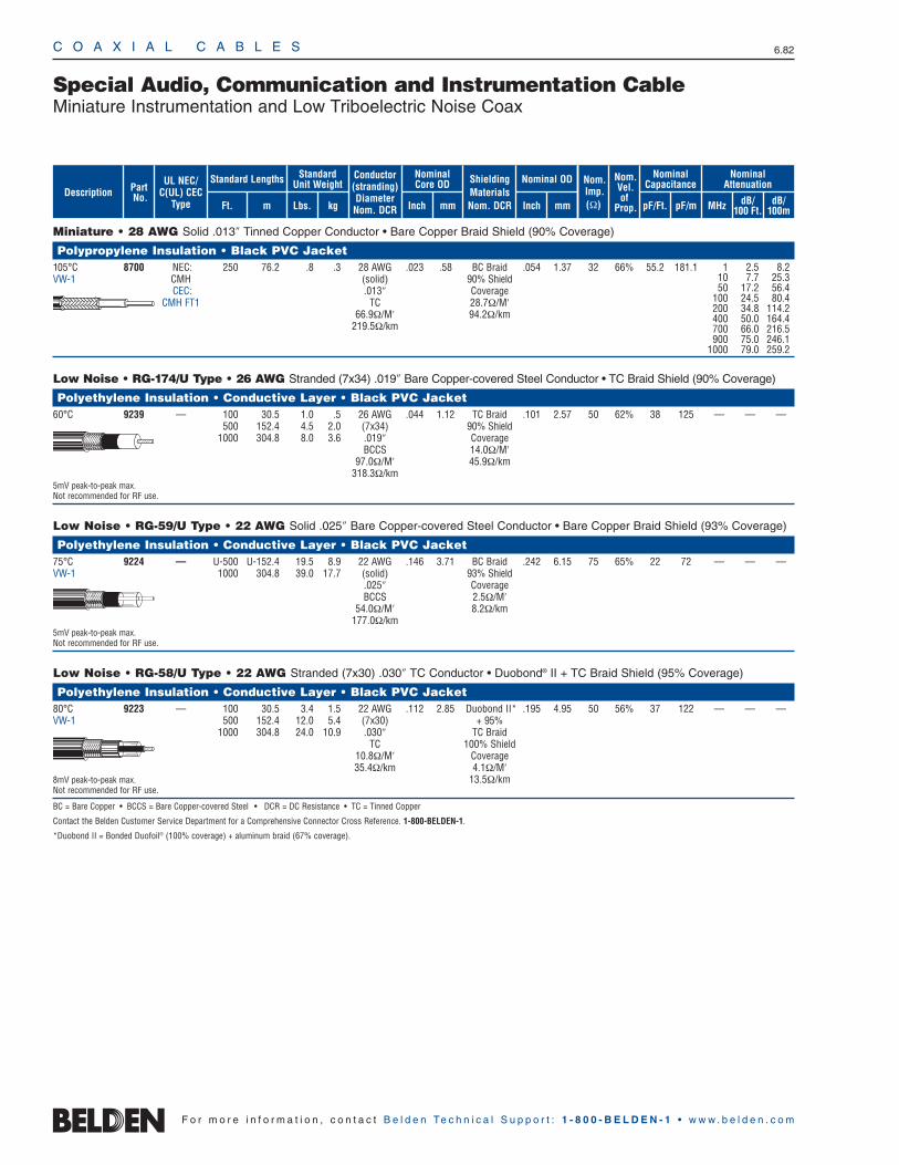
C O A X I A L C A B L E S 6.82
F o r m o r e i n f o r m a t i o n , c o n t a c t B e l d e n Te c h n i c a l S u p p o r t : 1 - 8 0 0 - B E L D E N - 1 • w w w . b e l d e n . c o m
Miniature • 28 AWG Solid .013″ Tinned Copper Conductor • Bare Copper Braid Shield (90% Coverage)
Polypropylene Insulation • Black PVC Jacket105°C 8700 NEC: 250 76.2 .8 .3 28 AWG .023 .58 BC Braid .054 1.37 32 66% 55.2 181.1VW-1 CMH (solid) 90% Shield
CEC: .013″ CoverageCMH FT1 TC 28.7Ω/M′
66.9Ω/M′ 94.2Ω/km219.5Ω/km
Low Noise • RG-174/U Type • 26 AWG Stranded (7x34) .019″ Bare Copper-covered Steel Conductor • TC Braid Shield (90% Coverage)
Polyethylene Insulation • Conductive Layer • Black PVC Jacket60°C 9239 — 100 30.5 1.0 .5 26 AWG .044 1.12 TC Braid .101 2.57 50 62% 38 125 — — —
500 152.4 4.5 2.0 (7x34) 90% Shield1000 304.8 8.0 3.6 .019″ Coverage
BCCS 14.0Ω/M′97.0Ω/M′ 45.9Ω/km
318.3Ω/km5mV peak-to-peak max.Not recommended for RF use.
Low Noise • RG-59/U Type • 22 AWG Solid .025″ Bare Copper-covered Steel Conductor • Bare Copper Braid Shield (93% Coverage)
Polyethylene Insulation • Conductive Layer • Black PVC Jacket75°C 9224 — U-500 U-152.4 19.5 8.9 22 AWG .146 3.71 BC Braid .242 6.15 75 65% 22 72 — — —VW-1 1000 304.8 39.0 17.7 (solid) 93% Shield
.025″ CoverageBCCS 2.5Ω/M′
54.0Ω/M′ 8.2Ω/km177.0Ω/km
5mV peak-to-peak max.Not recommended for RF use.
Low Noise • RG-58/U Type • 22 AWG Stranded (7x30) .030″ TC Conductor • Duobond® II + TC Braid Shield (95% Coverage)
Polyethylene Insulation • Conductive Layer • Black PVC Jacket80°C 9223 — 100 30.5 3.4 1.5 22 AWG .112 2.85 Duobond II* .195 4.95 50 56% 37 122 — — —VW-1 500 152.4 12.0 5.4 (7x30) + 95%
1000 304.8 24.0 10.9 .030″ TC BraidTC 100% Shield
10.8Ω/M′ Coverage35.4Ω/km 4.1Ω/M′
8mV peak-to-peak max. 13.5Ω/kmNot recommended for RF use.
BC = Bare Copper • BCCS = Bare Copper-covered Steel • DCR = DC Resistance • TC = Tinned Copper
Contact the Belden Customer Service Department for a Comprehensive Connector Cross Reference. 1-800-BELDEN-1.
*Duobond II = Bonded Duofoil® (100% coverage) + aluminum braid (67% coverage).
Special Audio, Communication and Instrumentation CableMiniature Instrumentation and Low Triboelectric Noise Coax
1 2.5 8.210 7.7 25.350 17.2 56.4
100 24.5 80.4200 34.8 114.2400 50.0 164.4700 66.0 216.5900 75.0 246.1
1000 79.0 259.2
ShieldingMaterialsNom. DCR
Nom.Imp.(Ω)
Nominal Core OD Nominal OD
Inch mm Inch mm
Conductor(stranding)DiameterNom. DCR
StandardUnit WeightStandard Lengths
Lbs. kgFt. m
UL NEC/C(UL) CEC
Type
PartNo.
MHz dB/100 Ft.
dB/100m
Nominal Attenuation
Nominal Capacitance
pF/mpF/Ft.
Nom.Vel.of
Prop.Description
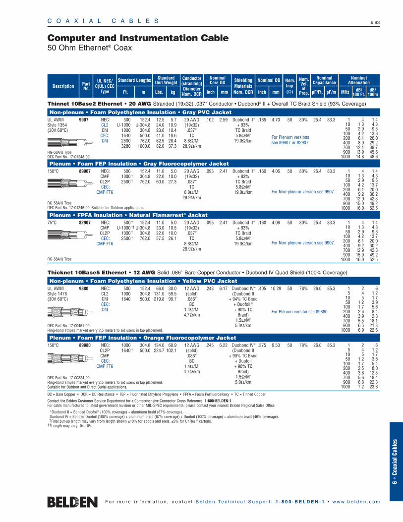
Thinnet 10Base2 Ethernet • 20 AWG Stranded (19x32) .037″ Conductor • Duobond® II + Overall TC Braid Shield (93% Coverage)
Non-plenum • Foam Polyethylene Insulation • Gray PVC JacketUL AWM 9907 NEC: 500 152.4 12.5 5.7 20 AWG .102 2.59 Duobond II* .185 4.70 50 80% 25.4 83.3Style 1354 CL2 U-1000 U-304.8 24.0 10.9 (19x32) + 93%(30V 60°C) CM 1000 304.8 23.0 10.4 .037″ TC Braid
CEC: 1640 500.0 41.0 18.6 TC 5.8Ω/M′CM 2500 762.0 62.5 28.4 8.8Ω/M′ 19.0Ω/km
3280 1000.0 82.0 37.3 28.9Ω/kmRG-58A/U TypeDEC Part No. 17-01248-00
Plenum • Foam FEP Insulation • Gray Fluorocopolymer Jacket150°C 89907 NEC: 500 152.4 11.0 5.0 20 AWG .095 2.41 Duobond II* .160 4.06 50 80% 25.4 83.3
CMP 1000 † 304.8 22.0 10.0 (19x32) + 93%CL2P 2500 † 762.0 60.0 27.3 .037″ TC BraidCEC: TC 5.8Ω/M′
CMP FT6 8.8Ω/M′ 19.0Ω/km28.9Ω/km
RG-58A/U TypeDEC Part No. 17-01246-00. Suitable for Outdoor applications.
Plenum • FPFA Insulation • Natural Flamarrest® Jacket75°C 82907 NEC: 500 † 152.4 11.0 5.0 20 AWG .095 2.41 Duobond II* .160 4.06 50 80% 25.4 83.3
CMP U-1000 †† U-304.8 23.0 10.5 (19x32) + 93%CL2P 1000 † 304.8 22.0 10.0 .037″ TC BraidCEC: 2500 † 762.0 57.5 26.1 TC 5.8Ω/M′
CMP FT6 8.8Ω/M′ 19.0Ω/km28.9Ω/km
RG-58A/U Type
Thicknet 10Base5 Ethernet • 12 AWG Solid .086″ Bare Copper Conductor • Duobond IV Quad Shield (100% Coverage)
Non-plenum • Foam Polyethylene Insulation • Yellow PVC JacketUL AWM 9880 NEC: 500 152.4 66.0 30.0 12 AWG .243 6.17 Duobond IV* .405 10.29 50 78% 26.0 85.3Style 1478 CL2 1000 304.8 131.0 59.5 (solid) (Duobond II(30V 60°C) CM 1640 500.0 219.8 99.7 .086″ + 94% TC Braid
CEC: BC + Duofoil ®
CM 1.4Ω/M′ + 90% TC4.7Ω/km Braid)
1.5Ω/M′DEC Part No. 17-00451-00 5.0Ω/kmRing-band stripes marked every 2.5 meters to aid users in tap placement.
Plenum • Foam FEP Insulation • Orange Fluorocopolymer Jacket150°C 89880 NEC: 1000 304.8 134.0 60.9 12 AWG .245 6.22 Duobond IV* .375 9.53 50 78% 26.0 85.3
CL2P 1640 † 500.0 224.7 102.1 (solid) (Duobond II CMP .086″ + 90% TC BraidCEC: BC + Duofoil
CMP FT6 1.4Ω/M′ + 90% TC4.7Ω/km Braid)
DEC Part No. 17-00324-00 1.5Ω/M′Ring-band stripes marked every 2.5 meters to aid users in tap placement. 5.0Ω/kmSuitable for Outdoor and Direct Burial applications.
BC = Bare Copper • DCR = DC Resistance • FEP = Fluorinated Ethylene Propylene • FPFA = Foam Perfluoroalkoxy • TC = Tinned Copper
Contact the Belden Customer Service Department for a Comprehensive Connector Cross Reference. 1-800-BELDEN-1. For cable manufactured to latest government revision or other MIL-SPEC requirements, please contact your nearest Belden Regional Sales Office.
*Duobond II = Bonded Duofoil® (100% coverage) + aluminum braid (67% coverage).Duobond IV = Bonded Duofoil (100% coverage) + aluminum braid (67% coverage) + Duofoil (100% coverage) + aluminum braid (46% coverage).†Final put-up length may vary from length shown ±10% for spools and reels, ±5% for UnReel® cartons.
††Length may vary -0/+10%.
C O A X I A L C A B L E S 6.83
6 •
Coax
ial C
able
s
F o r m o r e i n f o r m a t i o n , c o n t a c t B e l d e n Te c h n i c a l S u p p o r t : 1 - 8 0 0 - B E L D E N - 1 • w w w . b e l d e n . c o m
Computer and Instrumentation Cable50 Ohm Ethernet® Coax
1 .4 1.410 1.3 4.350 2.9 9.5
100 4.2 13.8200 6.1 20.0400 8.9 29.2700 12.1 39.7900 13.9 45.6
1000 14.8 48.6
1 .4 1.410 1.3 4.350 2.9 9.5
100 4.2 13.7200 6.1 20.0400 9.2 30.2700 12.9 42.3900 15.0 49.2
1000 16.0 52.5
1 .4 1.410 1.3 4.350 2.9 9.5
100 4.2 13.7200 6.1 20.0400 9.2 30.2700 12.9 42.3900 15.0 49.2
1000 16.0 52.5
1 .2 .65 .4 1.2
10 .5 1.750 1.2 3.9
100 1.7 5.6200 2.6 8.4400 3.9 12.8700 5.5 18.1900 6.5 21.3
1000 6.9 22.6
1 .2 .65 .4 1.2
10 .5 1.750 1.2 3.8
100 1.7 5.4200 2.5 8.0400 3.8 12.5700 5.6 18.4900 6.8 22.3
1000 7.2 23.6
For Plenum versionssee 89907 or 82907.
For Non-plenum version see 9907.
For Non-plenum version see 9907.
For Plenum version see 89880.
ShieldingMaterialsNom. DCR
Nom.Imp.(Ω)
Nominal Core OD Nominal OD
Inch mm Inch mm
Conductor(stranding)DiameterNom. DCR
StandardUnit WeightStandard Lengths
Lbs. kgFt. m
UL NEC/C(UL) CEC
Type
PartNo.
MHz dB/100 Ft.
dB/100m
Nominal Attenuation
Nominal Capacitance
pF/mpF/Ft.
Nom.Vel.of
Prop.Description
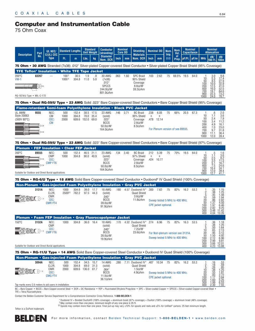
75 Ohm • 30 AWG Stranded (7x38) .012″ Silver-plated Copper-covered Steel Conductor • Silver-plated Copper Braid Shield (95% Coverage)
TFE Teflon® Insulation • White TFE Tape Jacket200°C 83267 — 100 † 30.5 1.9 .9 30 AWG .063 1.60 SPC Braid .103 2.62 75 69.5% 19.5 64.0VW-1 1000 † 304.8 11.0 5.0 (7x38) 95% Shield
.012″ CoverageSPCCS 8.6Ω/M′
244.0Ω/M′ 28.2Ω/km801.0Ω/km
RG-187A/U Type • MIL-C-17D
75 Ohm • Dual RG-59/U Type • 23 AWG Solid .023″ Bare Copper-covered Steel Conductors • Bare Copper Braid Shield (95% Coverage)
Flame-retardant Semi-foam Polyethylene Insulation • Black PVC JacketUL AWM 9555 NEC: 500 152.4 38.5 17.5 23 AWG .146 3.71 BC Braid .238 6.05 75 66% 20.5 67.3Style 20063 CM 1000 304.8 78.0 35.4 (solid) 95% Shield x x(300V 80°C) CEC: 2000 609.6 152.0 69.0 .023″ Coverage .478 12.14
CM BCCS 2.6Ω/M′50.0Ω/M′ 8.5Ω/km
164.0Ω/km
75 Ohm • Dual RG-59/U Type • 23 AWG Solid .023″ Bare Copper-covered Steel Conductors • Bare Copper Braid Shield (97% Coverage)
Plenum • FEP Insulation • Clear FEP Jacket200°C 89555 NEC: 500 152.4 46.5 21.1 23 AWG .134 3.40 BC Braid .212 5.39 75 70% 19.5 64.0
CMP 1000 304.8 90.0 40.9 (solid) 97% Shield x xCEC: .023″ Coverage .424 10.77
CMP FT6 BCCS 2.6Ω/M′50.0Ω/M′ 8.5Ω/km
164.0Ω/kmSuitable for Outdoor and Direct Burial applications.
75 Ohm • RG-6/U Type • 18 AWG Solid Bare Copper-covered Steel Conductor • Duobond® IV Quad Shield (100% Coverage)
Non-Plenum • Gas-injected Foam Polyethylene Insulation • Gray PVC Jacket3131A NEC: 1000 304.8 39.0 17.7 18 AWG .180 4.57 Duobond IV* .300 7.62 75 82% 16.2 53.2
CL2R, 2500†† 762.2 97.5 44.3 (solid) Quad ShieldCMR .040″ 3.6Ω/M′CEC: BCCS 11.8Ω/km
CMR FT4 28.0Ω/M′91.9Ω/km
Plenum • Foam FEP Insulation • Gray Fluorocopolymer Jacket150°C 3132A NEC: 1000 304.8 36.0 16.4 18 AWG .170 4.32 Duobond IV* .274 6.96 75 82% 16.3 53.5
CMP (solid) Quad ShieldCEC: .040″ 7.2Ω/M′
CMP FT6 BCCS 23.6Ω/km28.0Ω/M′19.9Ω/km
Suitable for Outdoor and Direct Burial applications.
75 Ohm • RG-11/U Type • 14 AWG Solid Bare Copper-covered Steel Conductor • Duobond IV Quad Shield (100% Coverage)
Non-Plenum • Gas-injected Foam Polyethylene Insulation • Gray PVC Jacket3094A NEC: 500 152.4 34.5 15.7 14 AWG .280 7.11 Duobond IV* .407 10.34 75 82% 16.2 53.2
CL2R, 1000 304.8 69.0 31.3 (solid) Quad ShieldCMR 2000 609.6 136.0 61.7 .064″ 1.5Ω/M′CEC: BCCS 4.9Ω/km
CMG FT4 11.0Ω/M′36.1Ω/km
Tap marks every 2.6 meters to aid users in installation.
BC = Bare Copper • BCCS = Bare Copper-covered Steel • DCR = DC Resistance • FEP = Fluorinated Ethylene Propylene • SPC = Silver-coated Copper • SPCCS = Silver-coated Copper-covered Steel •TFE = Tetra Fluoroethylene
Contact the Belden Customer Service Department for a Comprehensive Connector Cross Reference. 1-800-BELDEN-1.
* Duobond IV = Bonded Duofoil® (100% coverage) + aluminum braid (67% coverage) + Duofoil (100% coverage) + aluminum braid (46% coverage).† May contain more than one piece, minimum length of any one piece is 25 ft.
†† Spools may contain more than one piece. Final put-up may vary ±10% for spools and reels and ±5% for UnReel® cartons. 25 feet minimum length.
C O A X I A L C A B L E S 6.84
F o r m o r e i n f o r m a t i o n , c o n t a c t B e l d e n Te c h n i c a l S u p p o r t : 1 - 8 0 0 - B E L D E N - 1 • w w w . b e l d e n . c o m
Computer and Instrumentation Cable75 Ohm Coax
1 3.0 9.810 5.3 17.450 8.5 27.9
100 10.0 32.8200 12.5 41.0400 16.0 52.5700 19.7 64.6900 22.3 73.2
1000 24.0 78.7
1 .6 2.010 1.1 3.650 2.4 7.9
100 3.4 11.2200 4.9 16.1400 7.0 23.0700 9.7 31.8900 11.1 36.4
1000 12.0 39.4
1 .5 1.610 1.1 3.650 2.5 8.2
100 3.5 11.5200 5.1 16.7400 7.5 24.6700 10.4 34.1900 12.0 39.4
1000 12.7 41.7
For Plenum version of see 89555.
Sweep tested 5 MHz to 400 MHz.
CPE jacket optional.
For Non-plenum version see 3131A.
Sweep tested 5 MHz to 400 MHz.
Sweep tested 5 MHz to 400 MHz.
CPE jacket optional.
ShieldingMaterialsNom. DCR
Nom.Imp.(Ω)
Nominal Core OD Nominal OD
Inch mm Inch mm
Conductor(stranding)DiameterNom. DCR
StandardUnit WeightStandard Lengths
Lbs. kgFt. m
UL NEC/C(UL) CEC
Type
PartNo.
MHz dB/100 Ft.
dB/100m
Nominal Attenuation
Nominal Capacitance
pF/mpF/Ft.
Nom.Vel.of
Prop.Description
1 .35 1.152 .38 1.255 .45 1.48
10 .59 1.9420 .86 2.8250 1.37 4.50
100 1.97 6.46200 2.82 9.25300 3.48 11.42400 4.04 13.26
1 .36 1.182 .38 1.255 .50 1.64
10 .65 2.1320 .95 3.1250 1.50 4.92
100 2.12 6.96200 2.99 9.81300 3.66 12.01400 4.23 13.88
1 .16 .532 .18 .595 .26 .85
10 .38 1.2520 .55 1.8150 .83 2.72
100 1.17 3.84200 1.60 5.25300 1.99 6.53400 2.30 7.55
Teflon is a DuPont trademark.
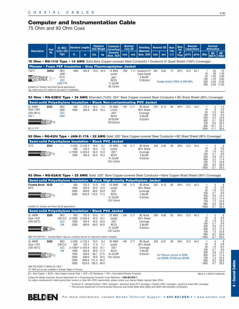
75 Ohm • RG-11/U Type • 14 AWG Solid Bare Copper-covered Steel Conductor • Duobond IV Quad Shield (100% Coverage)
Plenum • Foam FEP Insulation • Gray Fluorocopolymer Jacket150°C 3095A NEC: 1000 304.8 76.0 34.5 14 AWG .280 7.11 Duobond IV* .387 9.83 75 82% 16.5 54.1
CMP, (solid) Quad ShieldPLTC .064″ 3.9Ω/M′CEC: BCCS 12.8Ω/km
CMP FT6 11.0Ω/M′Suitable for Outdoor and Direct Burial applications. 36.1Ω/kmTap marks every 2.6 meters to aid users in installation.
93 Ohm • RG-62B/U Type • 24 AWG Stranded (7x32) .024″ Bare Copper-covered Steel Conductor • BC Braid Shield (95% Coverage)
Semi-solid Polyethylene Insulation • Black Non-contaminating PVC JacketUL AWM 8255 NEC: 500 152.4 16.5 7.5 24 AWG .146 3.71 BC Braid .242 6.15 93 84% 13.5 44.3Style 1354 CMX 1000 304.8 36.0 16.3 (7x32) 95% Shield(30V 60°C) CEC: .024″ CoverageVW-1 CMX BCCS 2.9Ω/M′
59.0Ω/M′ 9.5Ω/km193.6Ω/km
MIL-C-17D
93 Ohm • RG-62/U Type • JAN-C-17A • 22 AWG Solid .025″ Bare Copper-covered Steel Conductor • BC Braid Shield (95% Coverage)
Semi-solid Polyethylene Insulation • Black PVC Jacket75°C 8254 — U-500 U-152.4 18.0 8.2 22 AWG .146 3.71 BC Braid .238 6.05 93 84% 13.5 44.3
500 152.4 16.5 7.5 (solid) 95% ShieldU-1000 U-304.8 35.0 15.9 .025″ Coverage
1000 304.8 36.0 16.3 BCCS 2.9Ω/M′41.2Ω/M′ 9.5Ω/km
135.1Ω/km
93 Ohm • RG-62A/U Type • 22 AWG Solid .025″ Bare Copper-covered Steel Conductor • Bare Copper Braid Shield (95% Coverage)
Semi-solid Polyethylene Insulation • Black High-density Polyethylene JacketFlooded Burial 9228 — 500 152.4 15.0 6.8 22 AWG .146 3.71 BC Braid .242 6.15 93 84% 13.5 44.380°C 1000 304.8 33.0 15.0 (solid) 95% Shield
2000 609.6 68.0 30.9 .025″ Coverage5000 1524.0 170.0 77.3 BCCS 2.9Ω/M′
41.2Ω/M′ 9.5Ω/km135.1Ω/km
Suitable for Outdoor and Direct Burial applications.
Semi-solid Polyethylene Insulation • Black PVC JacketUL AWM 9268 NEC: 500 152.4 20.0 9.1 22 AWG .146 3.71 BC Braid .260 6.60 93 84% 13.5 44.3Style 1478 CM CL2 U-1000 U-304.8 42.0 19.1 (solid) 95% Shield(30V 60°C) CEC: 1000 304.8 44.0 20.0 .025″ Coverage
CM 2000 609.6 88.0 40.0 BCCS 2.9Ω/M′41.2Ω/M′ 9.5Ω/km
135.1Ω/km
IBM P/N 5252750 • Includes Mylar® tape as a moisture barrier for improved outdoor reliability.
UL AWM 9269 NEC: U-500 U-152.4 18.5 8.4 22 AWG .146 3.71 BC Braid .239 6.07 93 84% 13.5 44.3Style 1478 CM CL2 500 152.4 17.0 7.7 (solid) 95% Shield(30V 60°C) CEC: U-1000 U-304.8 36.0 16.7 .025″ Coverage
CM 1000 304.8 38.0 17.2 BCCS 2.9Ω/M′1640 500.0 60.7 27.5 41.2Ω/M′ 9.5Ω/km2000 609.6 76.0 34.5 135.1Ω/km3280 1000.0 121.4 55.05000 1524.0 185.0 84.0
IBM P/N 323921 P-MSHA SC-1823**U-1000 put-up also available in Orange, Beige or Chrome.
BC = Bare Copper • BCCS = Bare Copper-covered Steel • DCR = DC Resistance • FEP = Fluorinated Ethylene Propylene
Contact the Belden Customer Service Department for a Comprehensive Connector Cross Reference. 1-800-BELDEN-1.For cables manufactured to latest government revision or other MIL-SPEC requirements, please contact your nearest Belden regional Sales Office.
* Duobond IV = Bonded Duofoil® (100% coverage) + aluminum braid (67% coverage) + Duofoil (100% coverage) + aluminum braid (46% coverage).** Pennsylvania Department of Environmental Resources and United States Mine Safety and Health Administration Certification.
C O A X I A L C A B L E S 6.85
6 •
Coax
ial C
able
s
F o r m o r e i n f o r m a t i o n , c o n t a c t B e l d e n Te c h n i c a l S u p p o r t : 1 - 8 0 0 - B E L D E N - 1 • w w w . b e l d e n . c o m
Computer and Instrumentation Cable75 Ohm and 93 Ohm Coax
1 .3 .810 .9 2.850 1.9 6.2
100 2.7 8.9200 3.8 12.5400 5.3 17.4700 7.3 23.9900 8.2 26.9
1000 8.7 28.5
1 .3 .810 .9 2.850 1.9 6.2
100 2.7 8.9200 3.8 12.5400 5.3 17.4700 7.3 23.9900 8.2 26.9
1000 8.7 28.5
1 .3 .810 .9 2.850 1.9 6.2
100 2.7 8.9200 3.8 12.5400 5.3 17.4700 7.3 23.9900 8.2 26.9
1000 8.7 28.5
1 .3 .810 .9 2.850 1.9 6.2
100 2.7 8.9200 3.8 12.5400 5.3 17.4700 7.3 23.9900 8.2 26.9
1000 8.7 28.5
For Plenum version of 9269, see 89269, 87269 and 82269.
Sweep tested 5 MHz to 400 MHz.
ShieldingMaterialsNom. DCR
Nom.Imp.(Ω)
Nominal Core OD Nominal OD
Inch mm Inch mm
Conductor(stranding)DiameterNom. DCR
StandardUnit WeightStandard Lengths
Lbs. kgFt. m
UL NEC/C(UL) CEC
Type
PartNo.
MHz dB/100 Ft.
dB/100m
Nominal Attenuation
Nominal Capacitance
pF/mpF/Ft.
Nom.Vel.of
Prop.Description
1 .20 .7010 .39 1.3050 1.20 3.90
100 1.70 5.60200 2.50 8.20400 3.50 11.50
1 .3 1.010 .9 3.050 2.0 6.6
100 2.9 9.5200 4.2 13.8400 6.1 20.0700 8.6 28.2900 10.1 33.1
1000 11.1 36.4
Mylar is a DuPont trademark.

C O A X I A L C A B L E S 6.86
F o r m o r e i n f o r m a t i o n , c o n t a c t B e l d e n Te c h n i c a l S u p p o r t : 1 - 8 0 0 - B E L D E N - 1 • w w w . b e l d e n . c o m
RG-62/U Type • 22 AWG Solid .025″ Bare Copper-covered Steel Conductor • Bare Copper Braid Shield (94% Coverage)
Plenum • Semi-solid FEP Teflon® Insulation • Black or White Tint FEP Jacket200°C 89269 NEC: 100 30.5 5.2 2.4 22 AWG .142 3.61 BC Braid .200 5.08 93 85% 12.8 42.0
CMP 500 152.4 16.5 7.5 (solid) 94% ShieldCEC: 1000 304.8 33.0 15.0 .025″ Coverage
CMP FT6 BCCS 3.4Ω/M′41.2Ω/M′ 11.2Ω/km
135.2Ω/km100 ft. put-up available in Black only.Suitable for Outdoor and Direct Burial applications.
Plenum • Semi-solid FEP Teflon Insulation • Gray Fluorocopolymer Jacket150°C 87269 NEC: 1000 304.8 34.0 15.4 22 AWG .142 3.61 BC Braid .200 5.08 93 85% 12.8 42.0
CMP (solid) 94% ShieldCEC: .025″ Coverage
CMP FT6 BCCS 3.4Ω/M′41.2Ω/M′ 11.2Ω/km
135.2Ω/km
Suitable for Outdoor and Direct Burial applications.
Plenum • Semi-solid FEP Teflon Insulation • Natural Flamarrest® Low-smoke Jacket75°C 82269 NEC: 1000 304.8 30.0 13.6 22 AWG .142 3.61 BC Braid .200 5.08 93 85% 12.8 42.0
CMP (solid) 94% ShieldCEC: .025″ Coverage
CMP FT6 BCCS 3.4Ω/M′41.2Ω/M′ 11.2Ω/km
135.2Ω/km
Plenum • Foam FEP Teflon Insulation • White Tint FEP Jacket200°C 86262 NEC: 500 152.4 16.0 7.3 22 AWG .146 3.71 BC Braid .204 5.18 93 85% 12.5 41.0
CMP 1000 304.8 32.0 14.5 (solid) 94% ShieldCEC: .025″ Coverage
CMP FT6 BCCS 3.4Ω/M′41.2Ω/M′ 11.2Ω/km
135.2Ω/km
Suitable for Outdoor and Direct Burial applications.
Plenum • Foam FEP Teflon Insulation • Natural Flamarrest Jacket75°C 82262 NEC: U-1000 U-304.8 31.0 14.1 22 AWG .146 3.71 BC Braid .204 5.18 93 85% 12.5 41.0
CMP 1000 304.8 30.0 13.6 (solid) 94% ShieldCEC: .025″ Coverage
CMP FT6 BCCS 3.4Ω/M′41.2Ω/M′ 11.2Ω/km
135.2Ω/km
BC = Bare Copper • BCCS = Bare Copper-covered Steel • DCR = DC Resistance • FEP = Fluorinated Ethylene Propylene
Contact the Belden Customer Service Department for a Comprehensive Connector Cross Reference. 1-800-BELDEN-1.
Computer and Instrumentation Cable93 Ohm Coax
1 .3 1.010 .9 3.050 1.9 6.2
100 2.7 8.9200 3.8 12.5400 5.3 17.4700 7.3 23.9900 8.2 26.9
1000 8.7 28.5
1 .3 1.010 .9 3.050 1.9 6.2
100 2.7 8.9200 3.8 12.5400 5.3 17.4700 7.3 23.9900 8.2 26.9
1000 8.7 28.5
1 .3 1.010 .9 3.050 1.9 6.2
100 2.7 8.9200 3.8 12.5400 5.3 17.4700 7.3 23.9900 8.2 26.9
1000 8.7 28.5
1 .3 1.810 .9 3.050 1.9 6.2
100 2.7 8.9200 3.8 12.5400 5.3 17.4700 7.3 23.9900 8.2 26.9
1000 8.7 28.5
1 .3 1.810 .9 3.050 1.9 6.2
100 2.7 8.9200 3.8 12.5400 5.3 17.4700 7.3 23.9900 8.2 26.9
1000 8.7 28.5
ShieldingMaterialsNom. DCR
Nom.Imp.(Ω)
Nominal Core OD Nominal OD
Inch mm Inch mm
Conductor(stranding)DiameterNom. DCR
StandardUnit WeightStandard Lengths
Lbs. kgFt. m
UL NEC/C(UL) CEC
Type
PartNo.
MHz dB/100 Ft.
dB/100m
Nominal Attenuation
Nominal Capacitance
pF/mpF/Ft.
Nom.Vel.of
Prop.Description
Teflon is a DuPont trademark.
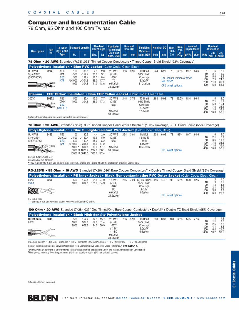
78 Ohm • 20 AWG Stranded (7x28) .038″ Tinned Copper Conductors • Tinned Copper Braid Shield (93% Coverage)
Polyethylene Insulation • Blue PVC Jacket (Color Code: Clear, Blue)UL AWM 9272 NEC: 100 30.5 4.5 2.0 20 AWG .156 3.96 TC Braid .244 6.20 78 66% 19.7 64.6Style 2092 CM U-500 U-152.4 20.0 9.1 (7x28) 93% Shield(300V 60°C) CEC: 500 152.4 18.5 8.4 .038″ Coverage
CM U-1000 U-304.8 39.0 17.7 TC 3.4Ω/M′1000 304.8 41.0 18.6 9.5Ω/M′ 11.2Ω/km
31.2Ω/km
Plenum • FEP Teflon® Insulation • Blue FEP Teflon Jacket (Color Code: Clear, Blue)200°C 89272 NEC: 500 152.4 17.0 7.7 20 AWG .148 3.76 TC Braid .198 5.03 78 69.5% 18.4 60.4
CMP 1000 304.8 38.0 17.3 (7x28) 93% ShieldCEC: .038″ Coverage
CMP FT6 TC 3.9Ω/M′9.5Ω/M′ 12.8v/km
31.2Ω/kmSuitable for Aerial applications when supported by a messenger.
78 Ohm • 20 AWG Stranded (7x28) .038″ Tinned Copper Conductors • Beldfoil® (100% Coverage) + TC Braid Shield (55% Coverage)
Polyethylene Insulation • Blue Sunlight-resistant PVC Jacket (Color Code: Clear, Blue)UL AWM 9463 NEC: 100 30.5 4.4 2.0 20 AWG .154 3.91 Beldfoil .238 6.05 78 66% 19.7 64.6Style 2464 CM CL2 U-500 U-152.4 19.5 8.9 (7x28) + 55% TC(300V 80°C) CEC: 500 152.4 18.0 8.2 .038″ Braid
CM U-1000 U-304.8 38.0 17.2 TC 4.1Ω/M′1000 304.8 39.0 17.7 9.5Ω/M′ 13.4Ω/km6000 † 1828.7 234.0 106.1 31.0Ω/km
10000 † 3048.0 380.0 172.4PMSHA P-7K-SC-182141*Allen Bradley P/N 1770-CD1000 ft. and 6000 ft. put-ups also available in Brown, Orange and Purple. 10,000 ft. available in Brown or Orange only.
RG-22B/U • 95 Ohm • 18 AWG Stranded (7x26) .046″ Bare Copper Conductors** • Double Tinned Copper Braid Shield (95% Coverage)
Polyethylene Insulation • PE Inner Jacket • Black Non-contaminating PVC Outer Jacket (Color Code: Clear, Clear)80°C 9250 — 500 152.4 61.5 27.9 18 AWG .285 7.24 (2) TC Braids .416 10.67 95 66% 16.0 52.5VW-1 1000 304.8 121.0 54.9 (7x26) 95% Shield
.046″ CoverageBC .9Ω/M′
6.6Ω/M′ 3.0Ω/km21.5Ω/km
RG-22B/U Type**1 conductor has tinned center strand. Non-contaminating PVC jacket.
100 Ohm • 20 AWG Stranded (7x28) .037″ One Tinned/One Bare Copper Conductors • Duofoil® + Double TC Braid Shield (95% Coverage)
Polyethylene Insulation • Black High-density Polyethylene JacketDirect Burial 9815 — 500 152.4 34.5 15.7 20 AWG .236 5.99 TC Braid .330 8.38 100 66% 14.5 47.680°C 1000 304.8 69.0 31.4 (7x28) 95% Shield
2000 609.6 134.0 60.9 .037″ Coverage(1) TC, 2.0Ω/M′(1) BC 6.6Ω/km
9.5Ω/M′31.0Ω/km
BC = Bare Copper • DCR = DC Resistance • FEP = Fluorinated Ethylene Propylene • PE = Polyethylene • TC = Tinned Copper
Contact the Belden Customer Service Department for a Comprehensive Connector Cross Reference. 1-800-BELDEN-1.
*Pennsylvania Department of Environmental Resources and United States Mine Safety and Health Administration Certification.†Final put-up may vary from length shown. ±10% for spools or reels, ±5% for UnReel® cartons.
C O A X I A L C A B L E S 6.87
6 •
Coax
ial C
able
s
F o r m o r e i n f o r m a t i o n , c o n t a c t B e l d e n Te c h n i c a l S u p p o r t : 1 - 8 0 0 - B E L D E N - 1 • w w w . b e l d e n . c o m
Computer and Instrumentation Cable78 Ohm, 95 Ohm and 100 Ohm Twinax
1 .6 2.010 2.1 6.950 5.0 16.4
100 7.5 24.6200 11.0 36.1400 16.0 52.5
1 .6 2.010 2.1 6.950 5.0 16.4
100 7.5 24.6200 11.0 36.1400 16.0 52.5
1 .6 2.010 2.1 6.950 3.6 11.8
100 7.5 24.6200 11.0 36.1400 16.0 52.5
1 .4 1.310 1.1 3.650 2.5 8.2
100 4.1 13.5200 6.4 21.0400 10.2 33.5
For Plenum version of 9272, see 89272.
CPE jacket optional.
CPE jacket optional.
CPE jacket optional.
ShieldingMaterialsNom. DCR
Nom.Imp.(Ω)
Nominal Core OD Nominal OD
Inch mm Inch mm
Conductor(stranding)DiameterNom. DCR
StandardUnit WeightStandard Lengths
Lbs. kgFt. m
UL NEC/C(UL) CEC
Type
PartNo.
MHz dB/100 Ft.
dB/100m
Nominal Attenuation
Nominal Capacitance
pF/mpF/Ft.
Nom.Vel.of
Prop.Description
1 .3 1.010 .9 3.020 1.3 4.350 2.1 6.9
100 3.0 9.8400 6.3 20.7
Teflon is a DuPont trademark.
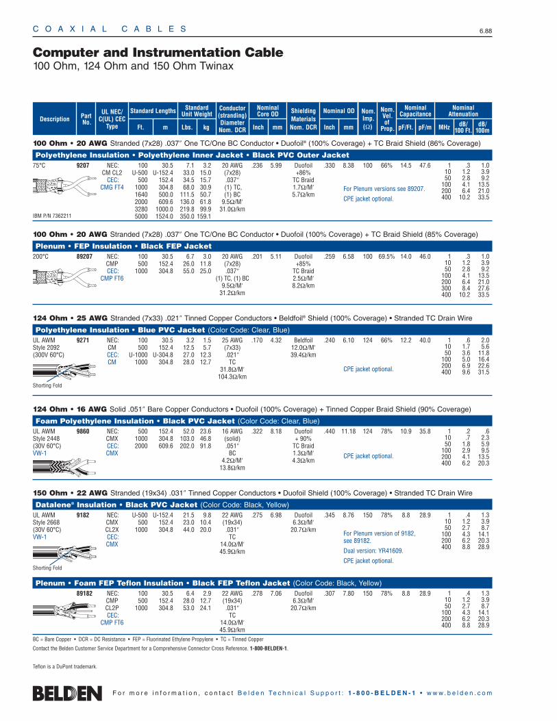
C O A X I A L C A B L E S 6.88
F o r m o r e i n f o r m a t i o n , c o n t a c t B e l d e n Te c h n i c a l S u p p o r t : 1 - 8 0 0 - B E L D E N - 1 • w w w . b e l d e n . c o m
100 Ohm • 20 AWG Stranded (7x28) .037″ One TC/One BC Conductor • Duofoil® (100% Coverage) + TC Braid Shield (86% Coverage)
Polyethylene Insulation • Polyethylene Inner Jacket • Black PVC Outer Jacket 75°C 9207 NEC: 100 30.5 7.1 3.2 20 AWG .236 5.99 Duofoil .330 8.38 100 66% 14.5 47.6
CM CL2 U-500 U-152.4 33.0 15.0 (7x28) +86%CEC: 500 152.4 34.5 15.7 .037″ TC Braid
CMG FT4 1000 304.8 68.0 30.9 (1) TC, 1.7Ω/M′1640 500.0 111.5 50.7 (1) BC 5.7Ω/km2000 609.6 136.0 61.8 9.5Ω/M′3280 1000.0 219.8 99.9 31.0Ω/km
IBM P/N 7362211 5000 1524.0 350.0 159.1
100 Ohm • 20 AWG Stranded (7x28) .037″ One TC/One BC Conductor • Duofoil (100% Coverage) + TC Braid Shield (85% Coverage)
Plenum • FEP Insulation • Black FEP Jacket200°C 89207 NEC: 100 30.5 6.7 3.0 20 AWG .201 5.11 Duofoil .259 6.58 100 69.5% 14.0 46.0
CMP 500 152.4 26.0 11.8 (7x28) +85%CEC: 1000 304.8 55.0 25.0 .037″ TC Braid
CMP FT6 (1) TC, (1) BC 2.5Ω/M′9.5Ω/M′ 8.2Ω/km
31.2Ω/km
124 Ohm • 25 AWG Stranded (7x33) .021″ Tinned Copper Conductors • Beldfoil® Shield (100% Coverage) • Stranded TC Drain Wire
Polyethylene Insulation • Blue PVC Jacket (Color Code: Clear, Blue)UL AWM 9271 NEC: 100 30.5 3.2 1.5 25 AWG .170 4.32 Beldfoil .240 6.10 124 66% 12.2 40.0Style 2092 CM 500 152.4 12.5 5.7 (7x33) 12.0Ω/M′(300V 60°C) CEC: U-1000 U-304.8 27.0 12.3 .021″ 39.4Ω/km
CM 1000 304.8 28.0 12.7 TC31.8Ω/M′
104.3Ω/km
124 Ohm • 16 AWG Solid .051″ Bare Copper Conductors • Duofoil (100% Coverage) + Tinned Copper Braid Shield (90% Coverage)
Foam Polyethylene Insulation • Black PVC Jacket (Color Code: Clear, Blue)UL AWM 9860 NEC: 500 152.4 52.0 23.6 16 AWG .322 8.18 Duofoil .440 11.18 124 78% 10.9 35.8Style 2448 CMX 1000 304.8 103.0 46.8 (solid) + 90%(30V 60°C) CEC: 2000 609.6 202.0 91.8 .051″ TC BraidVW-1 CMX BC 1.3Ω/M′
4.2Ω/M′ 4.3Ω/km13.8Ω/km
150 Ohm • 22 AWG Stranded (19x34) .031″ Tinned Copper Conductors • Duofoil Shield (100% Coverage) • Stranded TC Drain Wire
Datalene® Insulation • Black PVC Jacket (Color Code: Black, Yellow)UL AWM 9182 NEC: U-500 U-152.4 21.5 9.8 22 AWG .275 6.98 Duofoil .345 8.76 150 78% 8.8 28.9Style 2668 CMX 500 152.4 23.0 10.4 (19x34) 6.3Ω/M′(30V 60°C) CL2X 1000 304.8 44.0 20.0 .031″ 20.7Ω/kmVW-1 CEC: TC
CMX 14.0Ω/M′45.9Ω/km
Plenum • Foam FEP Teflon Insulation • Black FEP Teflon Jacket (Color Code: Black, Yellow)89182 NEC: 100 30.5 6.4 2.9 22 AWG .278 7.06 Duofoil .307 7.80 150 78% 8.8 28.9
CMP 500 152.4 28.0 12.7 (19x34) 6.3Ω/M′CL2P 1000 304.8 53.0 24.1 .031″ 20.7Ω/kmCEC: TC
CMP FT6 14.0Ω/M′45.9Ω/km
BC = Bare Copper • DCR = DC Resistance • FEP = Fluorinated Ethylene Propylene • TC = Tinned Copper
Contact the Belden Customer Service Department for a Comprehensive Connector Cross Reference. 1-800-BELDEN-1.
Teflon is a DuPont trademark.
Computer and Instrumentation Cable100 Ohm, 124 Ohm and 150 Ohm Twinax
1 .6 2.010 1.7 5.650 3.6 11.8
100 5.0 16.4200 6.9 22.6400 9.6 31.5
1 .2 .610 .7 2.350 1.8 5.9
100 2.9 9.5200 4.1 13.5400 6.2 20.3
1 .4 1.310 1.2 3.950 2.7 8.7
100 4.3 14.1200 6.2 20.3400 8.8 28.9
1 .4 1.310 1.2 3.950 2.7 8.7
100 4.3 14.1200 6.2 20.3400 8.8 28.9
Shorting Fold
Shorting Fold
ShieldingMaterialsNom. DCR
Nom.Imp.(Ω)
Nominal Core OD Nominal OD
Inch mm Inch mm
Conductor(stranding)DiameterNom. DCR
StandardUnit WeightStandard Lengths
Lbs. kgFt. m
UL NEC/C(UL) CEC
Type
PartNo.
MHz dB/100 Ft.
dB/100m
Nominal Attenuation
Nominal Capacitance
pF/mpF/Ft.
Nom.Vel.of
Prop.Description
CPE jacket optional.
CPE jacket optional.
For Plenum version of 9182, see 89182.
Dual version: YR41609.
CPE jacket optional.
1 .3 1.010 1.2 3.950 2.8 9.2
100 4.1 13.5200 6.4 21.0400 10.2 33.5
1 .3 1.010 1.2 3.950 2.8 9.2
100 4.1 13.5200 6.4 21.0300 8.4 27.6400 10.2 33.5
For Plenum versions see 89207.
CPE jacket optional.
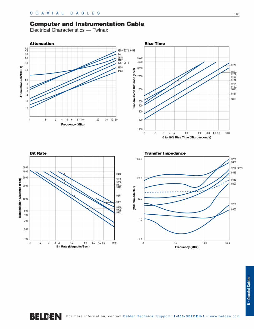
C O A X I A L C A B L E S 6.89
6 •
Coax
ial C
able
s
F o r m o r e i n f o r m a t i o n , c o n t a c t B e l d e n Te c h n i c a l S u p p o r t : 1 - 8 0 0 - B E L D E N - 1 • w w w . b e l d e n . c o m
Computer and Instrumentation CableElectrical Characteristics — Twinax
Attenuation
Att
enu
atio
n (
db
/100
Ft)
Frequency (MHz)
9859, 9272, 94639271
91829207, 9815
9250
9860
9851
.2
.3
.8
1.0
2.0
3.0
.40.6
4.0
5.06.07.0
1 2 3 4 5 6 8 10 20 30 40 50
Rise Time
0 to 50% Rise Time (Microseconds)
.1 .2 .3 .4 .5 1.0 3.02.0 4.0 5.0 10.0100
200
300
400
500
1000
2000
3000
4000
5000
Tra
nsm
issi
on
Dis
tan
ce (
Fee
t)
9271
9859,9272, 9463
9860
9182
9851
9250,9450, 9815
.1
Bit Rate
Bit Rate (Megabits/Sec.).2 .3 .4 .5 1.0 3.02.0 4.0 5.0 10.0
100
200
300
400
500
1000
2000
3000
4000
5000
Tra
nsm
issi
on
Dis
tan
ce (
Fee
t)
9851
9860
9250,9207,9815
9271
9859,9272,9463
9182
Transfer Impedance92719851
9272, 9859
9815
9463
9207
9250
9860
0.1
1.0
10.0
100.0
1000.0
.1 1.0 10.0 50.0
(Mill
ioh
ms/
Met
er)
Frequency (MHz)
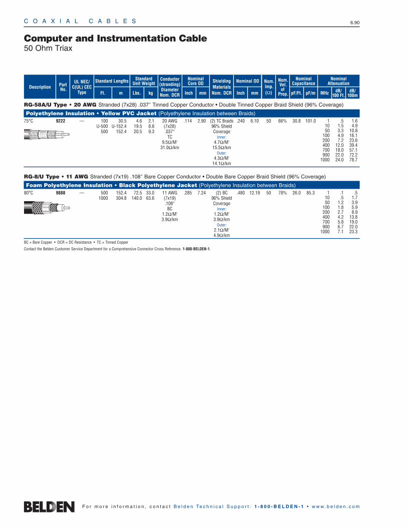
C O A X I A L C A B L E S 6.90
F o r m o r e i n f o r m a t i o n , c o n t a c t B e l d e n Te c h n i c a l S u p p o r t : 1 - 8 0 0 - B E L D E N - 1 • w w w . b e l d e n . c o m
RG-58A/U Type • 20 AWG Stranded (7x28) .037″ Tinned Copper Conductor • Double Tinned Copper Braid Shield (96% Coverage)
Polyethylene Insulation • Yellow PVC Jacket (Polyethylene Insulation between Braids)75°C 9222 — 100 30.5 4.6 2.1 20 AWG .114 2.90 (2) TC Braids .240 6.10 50 66% 30.8 101.0
U-500 U-152.4 19.5 8.8 (7x28) 96% Shield500 152.4 20.5 9.3 .037″ Coverage
TC Inner:9.5Ω/M′ 4.7Ω/M′
31.0Ω/km 15.5Ω/kmOuter:
4.3Ω/M′14.1Ω/km
RG-8/U Type • 11 AWG Stranded (7x19) .108″ Bare Copper Conductor • Double Bare Copper Braid Shield (96% Coverage)
Foam Polyethylene Insulation • Black Polyethylene Jacket (Polyethylene Insulation between Braids)80°C 9888 — 500 152.4 72.5 33.0 11 AWG .285 7.24 (2) BC .480 12.19 50 78% 26.0 85.3
1000 304.8 140.0 63.6 (7x19) 96% Shield.108″ Coverage
BC Inner:1.2Ω/M′ 1.2Ω/M′3.9Ω/km 3.9Ω/km
Outer:2.1Ω/M′4.9Ω/km
BC = Bare Copper • DCR = DC Resistance • TC = Tinned Copper
Contact the Belden Customer Service Department for a Comprehensive Connector Cross Reference. 1-800-BELDEN-1.
Computer and Instrumentation Cable50 Ohm Triax
1 .5 1.610 1.5 4.950 3.3 10.8
100 4.9 16.1200 7.2 23.6400 12.0 39.4700 18.0 57.1900 22.0 72.2
1000 24.0 78.7
1 .1 .510 .5 1.750 1.2 3.9
100 1.8 5.9200 2.7 8.9400 4.2 13.8700 5.8 19.0900 6.7 22.0
1000 7.1 23.3
ShieldingMaterialsNom. DCR
Nom.Imp.(Ω)
Nominal Core OD Nominal OD
Inch mm Inch mm
Conductor(stranding)DiameterNom. DCR
StandardUnit WeightStandard Lengths
Lbs. kgFt. m
UL NEC/C(UL) CEC
Type
PartNo.
MHz dB/100 Ft.
dB/100m
Nominal Attenuation
Nominal Capacitance
pF/mpF/Ft.
Nom.Vel.of
Prop.Description
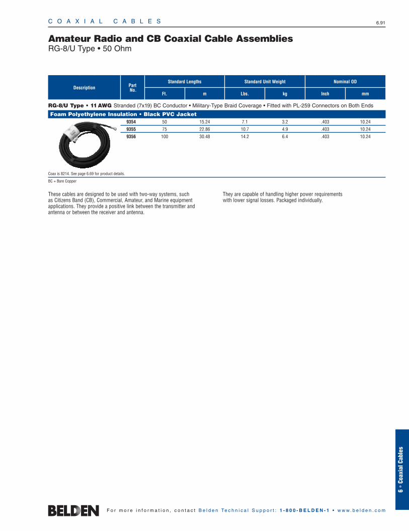
ShieldingMaterialsNom. DCR
Nom.Imp.(Ω)
Nominal Core OD Nominal OD
Inch mm Inch mm
Conductor(stranding)DiameterNom. DCR
StandardUnit WeightStandard Lengths
Lbs. kgFt. m
UL NEC/C(UL) CEC
Type
PartNo.
MHz dB/100 Ft.
dB/100m
Nominal Attenuation
Nominal Capacitance
pF/mpF/Ft.
Nom.Vel.of
Prop.Description
C O A X I A L C A B L E S 6.91
6 •
Coax
ial C
able
s
F o r m o r e i n f o r m a t i o n , c o n t a c t B e l d e n Te c h n i c a l S u p p o r t : 1 - 8 0 0 - B E L D E N - 1 • w w w . b e l d e n . c o m
RG-8/U Type • 11AWG Stranded (7x19) BC Conductor • Military-Type Braid Coverage • Fitted with PL-259 Connectors on Both Ends
Foam Polyethylene Insulation • Black PVC Jacket9354 50 15.24 7.1 3.2 .403 10.24
9355 75 22.86 10.7 4.9 .403 10.24
9356 100 30.48 14.2 6.4 .403 10.24
Coax is 8214. See page 6.69 for product details.
BC = Bare Copper
Amateur Radio and CB Coaxial Cable AssembliesRG-8/U Type • 50 Ohm
These cables are designed to be used with two-way systems, such as Citizens Band (CB), Commercial, Amateur, and Marine equipment applications. They provide a positive link between the transmitter and antenna or between the receiver and antenna.
They are capable of handling higher power requirements with lower signal losses. Packaged individually.
Nominal OD
Inch mm
Standard Unit WeightStandard Lengths
Lbs. kgFt. m
PartNo.Description
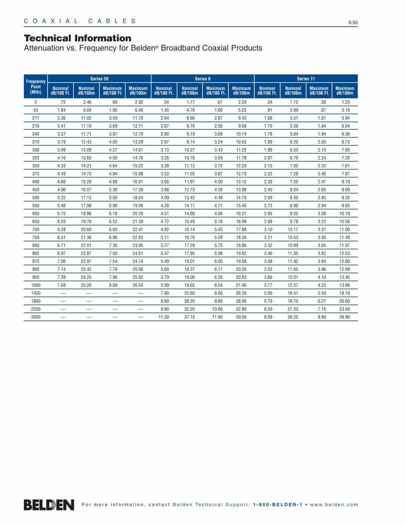
Frequency Point(MHz)
NominaldB/100 Ft.
NominaldB/100m
MaximumdB/100 Ft.
MaximumdB/100m
Series 59 Series 6
NominaldB/100 Ft.
NominaldB/100m
MaximumdB/100 Ft.
MaximumdB/100m
Series 11
NominaldB/100 Ft.
NominaldB/100m
MaximumdB/100 Ft.
MaximumdB/100m
C O A X I A L C A B L E S 6.92
Technical InformationAttenuation vs. Frequency for Belden® Broadband Coaxial Products
F o r m o r e i n f o r m a t i o n , c o n t a c t B e l d e n Te c h n i c a l S u p p o r t : 1 - 8 0 0 - B E L D E N - 1 • w w w . b e l d e n . c o m
5 .75 2.46 .89 2.92 .54 1.77 .67 2.20 .34 1.12 .38 1.25
55 1.84 6.04 1.95 6.40 1.45 4.76 1.60 5.25 .91 2.99 .97 3.18
211 3.36 11.02 3.59 11.78 2.64 8.66 2.87 9.42 1.68 5.51 1.81 5.94
216 3.41 11.19 3.69 12.11 2.67 8.76 2.95 9.68 1.70 5.58 1.84 6.04
240 3.57 11.71 3.87 12.70 2.80 9.19 3.09 10.14 1.78 5.84 1.94 6.36
270 3.79 12.43 4.05 13.29 2.97 9.74 3.24 10.63 1.89 6.20 2.05 6.73
300 3.99 13.09 4.27 14.01 3.13 10.27 3.43 11.25 1.99 6.53 2.15 7.05
325 4.16 13.65 4.50 14.76 3.26 10.70 3.59 11.78 2.07 6.79 2.24 7.35
350 4.33 14.21 4.64 15.22 3.39 11.12 3.72 12.20 2.15 7.05 2.32 7.61
375 4.49 14.73 4.84 15.88 3.52 11.55 3.87 12.70 2.22 7.28 2.40 7.87
400 4.66 15.29 4.88 16.01 3.65 11.97 4.00 13.12 2.30 7.55 2.47 8.10
450 4.96 16.27 5.30 17.39 3.88 12.73 4.26 13.98 2.45 8.04 2.65 8.69
500 5.22 17.13 5.50 18.04 4.09 13.42 4.48 14.70 2.59 8.50 2.85 9.35
550 5.48 17.98 5.90 19.36 4.30 14.11 4.71 15.45 2.73 8.96 2.94 9.65
600 5.75 18.86 6.18 20.28 4.51 14.80 4.94 16.21 2.85 9.35 3.08 10.10
650 6.03 19.78 6.52 21.39 4.72 15.49 5.18 16.99 2.98 9.78 3.22 10.56
700 6.28 20.60 6.83 22.41 4.92 16.14 5.45 17.88 3.10 10.17 3.37 11.06
750 6.51 21.36 6.96 22.83 5.11 16.76 5.59 18.34 3.21 10.53 3.50 11.48
800 6.71 22.01 7.30 23.95 5.27 17.29 5.75 18.86 3.32 10.89 3.65 11.97
862 6.97 22.87 7.50 24.61 5.47 17.95 5.98 19.62 3.46 11.35 3.82 12.53
870 7.00 22.97 7.54 24.74 5.49 18.01 6.00 19.68 3.48 11.42 3.84 12.60
900 7.14 23.42 7.79 25.56 5.60 18.37 6.11 20.05 3.55 11.65 3.96 12.99
950 7.39 24.25 7.90 25.92 5.79 19.00 6.35 20.83 3.66 12.01 4.10 13.45
1000 7.68 25.20 8.09 26.54 5.99 19.65 6.54 21.46 3.77 12.37 4.23 13.88
1450 — — — — 7.80 25.60 8.00 26.20 5.00 16.41 5.50 18.10
1800 — — — — 8.60 28.20 8.80 28.90 5.70 18.70 6.27 20.60
2250 — — — — 9.80 32.20 10.00 32.80 6.50 21.33 7.15 23.50
3000 — — — — 11.30 37.10 11.90 39.00 8.00 26.25 8.80 28.90