Coastal Erosion Prevention by Geotextile Tube Technology
41
COASTAL EROSION PREVENTION BY GEOTEXTILE TUBE TECHNOLOGY SEMINAR REPORT Submitted by DEEPA. K. A. M 2 Geotechnical Engineering Roll No. 091224 1
-
Upload
nanda-krishnan -
Category
Documents
-
view
63 -
download
1
description
POIT
Transcript of Coastal Erosion Prevention by Geotextile Tube Technology

COASTAL EROSION PREVENTION BY
GEOTEXTILE TUBE TECHNOLOGY
SEMINAR REPORT
Submitted by
DEEPA. K. A.
M2 Geotechnical Engineering
Roll No. 091224
1

DEPARTMENT OF CIVIL ENGINEERING
COLLEGE OF ENGINEERING
TRIVANDRUM - 16
2010
COASTAL EROSION PREVENTION BY
GEOTEXTILE TUBE TECHNOLOGY
SEMINAR REPORT
Submitted in partial fulfilment of
the requirements for the award of M. Tech Degree in
2

Civil Engineering
(Geotechnical Engineering)
of the University of Kerala
Submitted by
DEEPA. K. A.
M2, Roll No. 091224
Guided by
Dr. P. VINOD
Assistant Professor
DEPARTMENT OF CIVIL ENGINEERING
3
COLLEGE OF ENGINEERING
TRIVANDRUM – 16
2010
DEPARTMENT OF CIVIL ENGINEERING
COLLEGE OF ENGINEERING
TRIVANDRUM - 16
UNIVERSITY OF KERALA
2010
BONAFIDE CERTIFICATE
4
This is to certify that this report titled “COASTAL EROSION PREVENTION BY GEOTEXTILE TUBE
TECHNOLOGY” is a bonafide record of the work done by DEEPA. K. A. (M2, Roll No.091224
Geotechnical Engineering) towards the partial fulfilment of the requirements for the award of M.
Tech. Degree in Civil Engineering (Geotechnical Engineering) of the University of Kerala during the
year 2010.
Guided by P.G. Professor
Dr. P. VINOD Dr. V. SYAM PRAKASH
Assistant Professor, P.G. Professor
Dept of Civil Engineering Dept of Civil Engineering
College of Engineering, College of Engineering,
Trivandrum. Trivandrum.
ACKNOWLEDGEMENT
I express my deep sense of gratitude to my guide Dr. P. Vinod, Assistant Professor,
Department of Civil Engineering, College of Engineering Trivandrum, for the valuable guidance,
constant encouragement and creative suggestions offered during the course of this seminar and
also in preparing this report.
5
I express my sincere thanks to Prof. Sheela S, Head of the Department, Department of Civil
Engineering, College of Engineering Trivandrum, for her valuable support and advice.
I express my sincere thanks to Dr. V. Syam Prakash, P.G Professor, Prof. Mariamma Joseph,
Head of the Geotechnical Division, Dr. S. Sreekumar, Staff Advisor, Prof. Ajitha Bhaskar and Dr.
Girish M S, Seminar Co-ordinators Department of Civil Engineering, College of Engineering
Trivandrum for providing necessary facilities and their sincere co-operation.
My sincere thanks are extended to all the teachers of the department of Civil Engineering and
to all my friends for their help and support.
Above all I thank GOD, the almighty for his grace without which it would not have been
possible to complete this work in time.
DEEPA. K.A.
TABLE OF CONTENTS
TITLE PAGE NO.
6

1. INTRODUCTION 1
1.1 DESIGN CONSIDERATIONS OF GEOTEXTILE TUBES 2
1.1.1 Properties of the filling material 2
1.1.2 Mechanical properties of geotextiles 2
1.1.3 Hydrodynamic stability 2
1.2 GEOTEXTILE TUBE SHAPE 3
1.3 HYDRAULIC STABILITY ANALYSIS OF GEOTEXTILE TUBES 4
2. INSTALLATION OF A GEOTEXTILE TUBE 6
2.1 Site Investigation 8
2.2 Site Preparation 8
2.3 Transporting the Slurry 9
2.4 Filling 10
2.5 Dewatering 11
3. CASE HISTORY 11
3.1 COASTAL EROSION PREVENTION MEASURES AT A BEACH
LOCATED AT THE EAST COAST OF KOREA 11
3.1.1 Site Description 11
3.1.2 2-D hydraulic stability analysis 13
3.1.3 Design and construction 15
3.1.4 Installation 15
3.1.5 Observation after construction 16
3.2 COASTAL EROSION PREVENTION MEASURES
AT A BEACH IN MEXICO 17
4. SUMMARY AND CONCLUSIONS 19
REFERENCES 20
ABSTRACT
7

The use of geotextile in Civil Engineering applications is quite large and has
expanded very rapidly worldwide especially during the last decade. Supported by the
technological boom, geotextiles have invaded a large variety of domains and have won trust
and esteem around the world because of the advantages they guarantee in terms of easiness
and flexibility of use, rapidity of installation and long-term efficiency. Shore erosion is
currently causing millions of dollars worth of damage to shorelines and public properties
around the world. Without adequate protection, a very significant part of our coastline will
fall prey to the ravages of the sea. In recent years, because of the shortage of natural rock,
traditional forms of river and coastal structures have become very expensive to build and
maintain. Consequently, the materials used in hydraulic and coastal structures are changing
from the traditional rubble and concrete systems to cheaper materials and systems. One of
these alternatives employs geotextile tube technology in the construction of shore protection
structures, such as groins, jetties, detached breakwaters and so on. Recently, geotextile tube
technology has changed from being an alternative construction technique and, in fact, has
advanced to become the most effective solution of choice.
This report explains the design considerations, hydraulic stability analysis and also
the installation of geotextile tubes. The report also presents a few case histories where the
geotextile tube technology has been successfully implemented for shore line protection.
8

1. INTRODUCTION
In recent years, traditional forms of river and coastal structures have become very
expensive to build and maintain because of shortage of natural rock. As a consequence, the
materials used in hydraulic and coastal structures are changing from traditional rubble and
concrete systems to cheaper materials and systems such as gabion, slags, geosynthetics and
so on. Moreover shorelines are being continually eroded by the wave action of the sea.
Geosynthetics are being increasingly used in civil and environmental applications. One of
these applications is the use of geotextile tube technology. Geotextile tubes, hydraulically or
mechanically filled with dredged materials, have been variously applied in hydraulic and
coastal engineering fields.
The geotextile tube technology is mainly used for flood and water control, but they
are also used to prevent beach erosion, and for shore protection and environmental
applications (Shin and Oh, 2007). The geotextile sheets are permeable, yet soil tight, so that
any excess water drains from the geotextile tube. This causes the tube height to decrease, so
that the tube may have to be pumped more than once in order to achieve the desired height
(Shin and Oh, 2007). There are inlets at the upper part of the tube where the pumping hose is
inserted. The number and interval of inlets are dependent upon the type of the soil being
used. Typical lengths and widths of geotextile tubes are 150-180 and 4-5m, respectively,
with the effective height of 1.5-2.0m (Shin and Oh, 2007). Some of the most attractive
advantages of geotextile tube technology are that it can be used for in-situ filling materials
by hydraulic pumping; it can also be implemented with lower costs and faster construction
than other technology. Because of the lower price and easier installation, geotextile tube
systems can be good alternatives for hydraulic and coastal structures. Dikes and levees are
among primary uses of geotextile tubes. Dikes up to 2.0m tall can be constructed to provide
flood protection. By stacking the tubes, an even greater height can be achieved. These tubes
9

can also be attached to the top of a floodwall to provide greater flood control (Shin and Oh,
2007). Groins can be very effective when used for shoreline protection. Sand-filled
geotextile bags are a very reasonable alternative to other groin types. Sand-filled can also be
used for revetments or bulkhead protection (Shin and Oh, 2007). For geotextile tubes the
major design considerations are related to the integrity of the units during release and
impact, and the accuracy of placement and the stability under current and wave attack (Shin
and Oh, 2007).
1.1 DESIGN CONSIDERATIONS OF GEOTEXTILE TUBES
The following design aspects are of importance:
1.1.1 Properties of the filling material
The physical characteristics of the filling material are important factors of geotextile
tube design and construction. Types of soil and degree of saturation influence the final
geotextile tube shape. Field experience has demonstrated that it is possible to fill in the
geotextile tubes to 70% or 80% of the theoretical maximum circular diameter. The dredged
material filled in the geotextile can be any material capable of being transported
hydraulically. Naturally occurring beach or river sand is the perfect choice for structural fill.
1.1.2 Mechanical properties of geotextiles
The retention of fill and the structural integrity of a dredged material-filled tube are
provided by geotextile envelope. Functionally, geotextile selection is based on the
geotextile’s opening characteristics, which must match the fill particle size and permeability,
and must have sufficient strength to resist the filling pressures. A composite fabric shell is
sometimes used, since it incorporates both an inner non woven fabric for filtration and an
outer woven fabric for strength. Formulation of a geotextile tube, filled with pressurized
slurry or fluid, is based on the equilibrium of the encapsulating flexible shell.
1.1.3 Hydrodynamic stability
10

Hydrodynamic stability is a very important factor for coastal and near shore
geotextile tube construction. In order to assess the stability of the filled geotextile tube
structure, current wave forces are to be estimated.
1.2 GEOTEXTILE TUBE SHAPE
To predict the tube shape filled with coarse-grained material is easier than that with
fine grained material, because of immediate settlement and effective free drainage of coarse
grained material. One of the methods to predict the tube shape variation with consolidation
process is the volume reduction method.
Volume reduction method
The volume reduction method (VRM) provides the tube height variation with the
desired density of slurry based on the volume-weight relationship. The governing
mechanism of this approximation is that the tube only change sits height during the
consolidation process. Also the approximation options of the computer program GeoCoPS
are two shape types (elliptical and rectangle); it was selected by the magnitude of height
drop, desired density, and final tube shape. To simplify the boundary condition and
influencing factor, the following assumptions are considered in these approaches:
The consolidating material has one-dimensional movement
The solidified slurry is fully saturated
The tensile strength of geotextile is ignored
The slurry density is uniformed
From the assumptions and using the basic volume weight relationships, the following
equation is obtained:
11

= = = ……………………................. (1)
Where and are the decrease and the initial height of the tube, respectively, is the
specific gravity of the solid, is the initial void ratio, and and the initial and final
water contents of the fill material. The following equation can also be shown:
, ………………………….. (2)
Where and are the unit weights of slurry and consolidated soil, respectively.
By combining equations (1) and (2), the decrease in tube height can be estimated with
material inside densities.
1.3 HYDRAULIC STABILITY ANALYSIS OF GEOTEXTILE TUBES
The main problem in geotextile tube technology is lack of proper design criteria such
as hydraulic stability, structural functionality, and knowledge of their behavior during and
after construction. In the past, the design of these systems was mostly based on rather vague
experience than on valid calculational methods. More research, especially concerning large-
12
scale tests and the evaluation of performance of projects already realized, is still needed.
The hydraulic stability analysis based on the 2-D limit equilibrium theory is briefly
described below.
2-D hydraulic stability analysis
Several causes are responsible for the structural failure of geotextile tube structures.
The hydraulic structural failure including sliding, overturning, bearing capacity failure, and
rotating and forcing associated with waves. In order to assess the stability of the filled
geotextile tube structure, current wave forces have to be estimated. The theoretical stability
analysis employed is 2-D hydraulic stability analysis, based on the linear wave theory and
geotechnical stability analysis method. The hydrodynamic pulsating load to a geotextile tube
is evaluated by Hiroi’s empirical equation and is given by:
= 1.5 …………………………………………………………………………... (3)
Where is the hydrodynamic pulsating load, the unit weight of water, and the
significant wave height. The gravity weight of a geotextile tube was calculated by
equivalent rectangular shape in the effective height. The factor of safety against sliding can
be expressed by:
= = …………………………………………………………… (4)
Where is the horizontal resistance, is the horizontal force, is the overburden
pressure and gravity weight of geotextile tube, is the hydrodynamic pulsating load,
the effective height, and the interface angle between the geotextile and the base sand. The
13

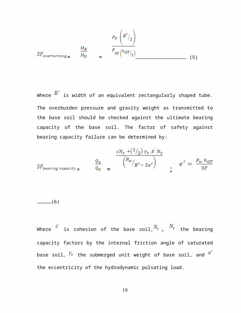
factor of safety against overturning about the toe of an equivalent rectangularly shaped tube
can be expressed by:
= = ……………………………………………… (5)
Where is width of an equivalent rectangularly shaped tube. The overburden pressure and
gravity weight as transmitted to the base soil should be checked against the ultimate bearing
capacity of the base soil. The factor of safety against bearing capacity failure can be
determined by:
= = ; ……………(6)
Where is cohesion of the base soil, , the bearing capacity factors by the internal
friction angle of saturated base soil, the submerged unit weight of base soil, and the
eccentricity of the hydrodynamic pulsating load.
2. INSTALLATION OF A GEOTEXTILE TUBE
14

A geotextile tube is a structure in the form of a tube made of a highly-resistant
geotextile woven envelope filled with materials. Sand is the best filling material, mostly
thanks to its incompressibility; but other types of pumpable inert materials can also be used.
The structure is built on site and filled through hydraulic pumping of local materials
inside the envelope. The structure is flexible, monolithic, continual, and very resistant to
water forces. The tube is made of a special geotextile produced to suit specific types of
applications. The geotextile has small pores capable of retaining the injected materials and
allowing, due to a great permeability, the flow out of water during the pumping phase
(Koffler et al. 2008). In addition, the geotextile, is highly strong, to resist the high tensions
occurring during the hydraulic filling and maintain its geometrical shape.
The tubes are custom-made and supplied in various sizes and lengths to suit design
and installation requirements, with a great variety of diameters and lengths according to
specific applications. The structure is normally dimensioned by the theoretical diameter, the
circumference and the length. The theoretical diameter of the tube normally ranges from
1.50 m to 5 m. Filling is carried out on site through a series of inlet ports placed on a regular
basis along the tube.
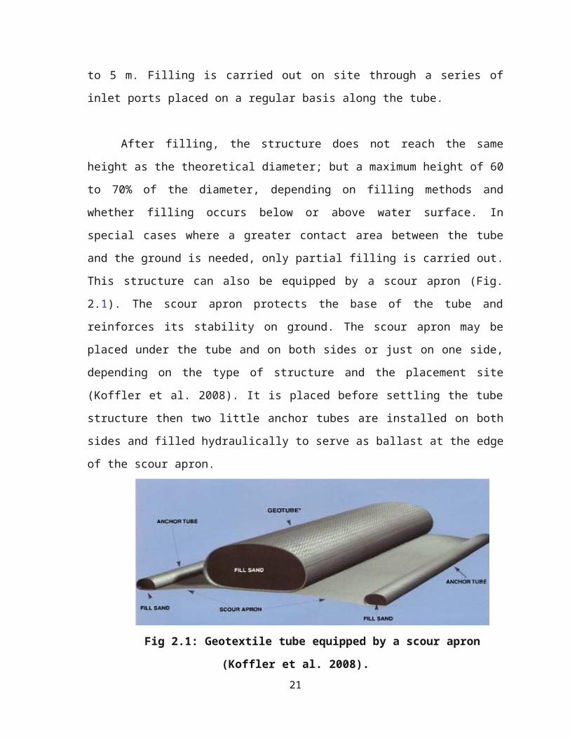
After filling, the structure does not reach the same height as the theoretical diameter;
but a maximum height of 60 to 70% of the diameter, depending on filling methods and
whether filling occurs below or above water surface. In special cases where a greater contact
area between the tube and the ground is needed, only partial filling is carried out. This
structure can also be equipped by a scour apron (Fig. 2.1). The scour apron protects the base
of the tube and reinforces its stability on ground. The scour apron may be placed under the
tube and on both sides or just on one side, depending on the type of structure and the
placement site (Koffler et al. 2008). It is placed before settling the tube structure then two
little anchor tubes are installed on both sides and filled hydraulically to serve as ballast at the
edge of the scour apron.
15
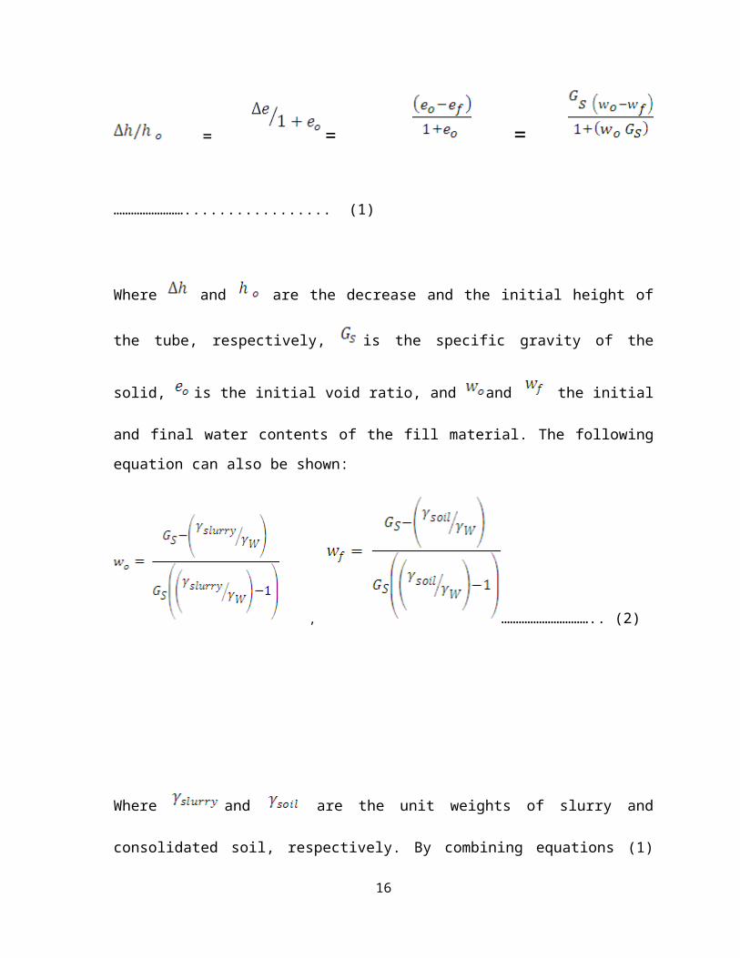
Fig 2.1: Geotextile tube equipped by a scour apron (Koffler et al. 2008).
Different types of pumps are used to carry out the filling, ranging from
unsophisticated sinkable pumps to huge dredging pumps according to the needs. The type of
pumping system depends on the importance and complexity of the project and the specificity
of the site. The hydraulic pump is connected to local inlet ports placed along the tube.
A mixture of sand and water is pumped into the tube. The sand settles inside the
geotextile tube and the water “bleeds” from the pores of the geotextile and the filling
progresses. So, the inlet ports that are not used during the filling operation should be left
open to allow the evacuation of excess water. When the tube is filled to the required height,
the inlet ports are seamed (Koffler et al. 2008). Stresses in the encapsulating geosynthetics
due to slurry pumping pressure, makes the installation procedure a task that must be carried
out under extremely controlled conditions. The geotextile tubes after filling process
completed are shown in Fig 2.2 and 2.3.
Fig 2.2: Installation of geotextile tube (Koffler et al. 2008).
16
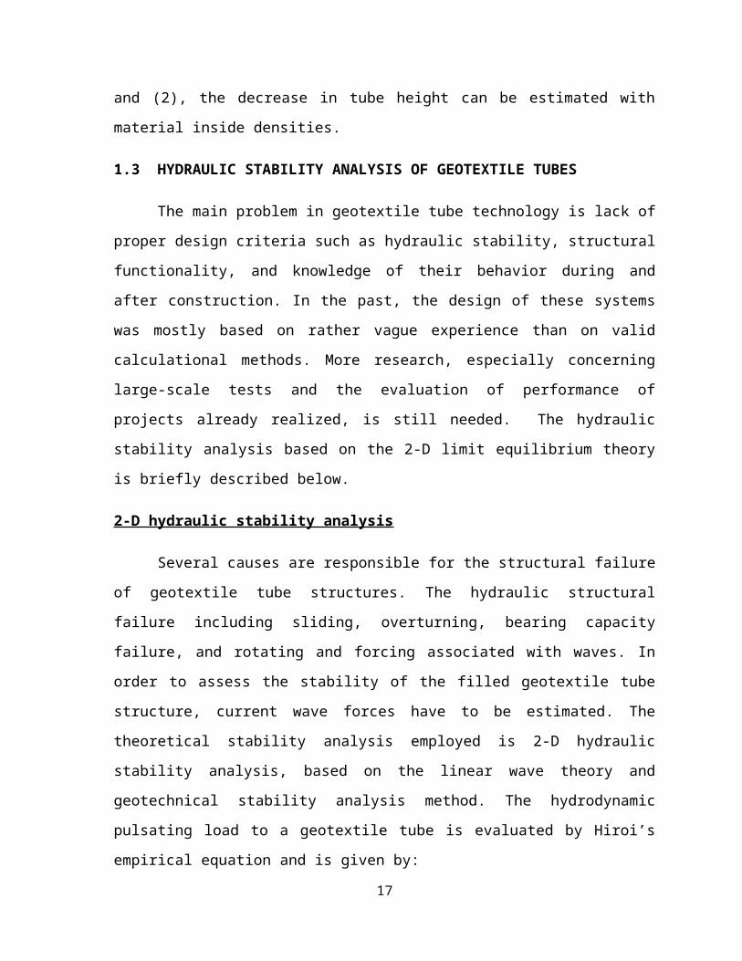
Fig 2.3: Installation of a geotextile tube – filling completed (Koffler et al. 2008).
The installation procedure of geotextile tubes involve:
2.1 Site Investigation
Installation begins with a site investigation to determine factors that influence the
operations of an installation. First, the site must be evaluated to determine what equipment is
needed to complete the installation. The amount of pipe needed to transport the slurry from
the dredge to the geotextile tube must be determined. It is determined at this time if any
special equipment is needed in the operations. A site investigation determines the optimum
time of day to begin the site preparation in regards to tides, currents, and waterway traffic (it
will be less difficult at low tide with less traffic). Finally, all environmental concerns are
determined through the site investigation.
2.2 Site Preparation
Preparing the site for a geotextile tube installation begins with assembling the proper
equipment as predetermined by the site investigation. Some sites require leveling the area
(dry land) or digging a trench to aid the stability of the geotextile tube during filling. Site
preparation includes installing the scour apron (Fig 2.4). Once the apron and geotextile tubes
are in place and stabilized, filling can begin.
17

Fig 2.4: Installation of a Scour Apron (Murphy, 1998).
2.3 Transporting the Slurry
There are two basic methods to transport the slurry to fill the geotextile tube. The
first method uses a small dredge just for filling the geotextile tube and the discharge pipeline
is connected directly to the geotextile tube. The second method is to use the normal dredge
and utilize a split pipe technique to fill the geotextile tube as seen from Fig 2.5. A ball valve
can be used to control the slurry pressure into the geotextile tube. If this method is used,
careful attention to the velocities must be considered to prevent the pipes from clogging.
Both methods have been used and have been successful. The determining factors for
selecting which method to use are economics and the size of the dredging project.
Fig 2.5: Split Pipe Method (Sprague, 1993).
18
2.4 Filling
Once the method of dredging and transporting the slurry is determined and the site
has been prepared, then filling the geotextile tube can begin. The geotextile tube must be
restrained while filling because it will take some time for the solids to accumulate inside the
geotextile tube. Once there is enough buildup of solids accumulation, then the geotextile
tube will stabilize itself. However, even though one end of the geotextile tube is stable, it
still may be necessary to restrain the empty end because it may twist and roll. Depending on
the dredge, it may be necessary to hold the discharge pipe with a frame, backhoe, or crane
near the filling port for support. With a small dredge, the discharge line can usually be
directly connected to the fill port. A pressure gauge can be used to monitor the pressure
inside the geotextile tube as illustrated in Fig 2.6. Using GeoCoPS can aid in the filling
procedure by determining the pumping pressure needed to obtain a specific height of a
geotextile tube. It is important not to over pressurize the geotextile tube during filling for
obvious reasons. This is achieved by watching the pressure and leaving the fill holes open to
allow the water to escape more rapidly.
Fig 2.6: Pressure Gauge Connected to Inlet (Leshchinsky et al., 1996).
19
The dredge material also affects the filling procedure. If the sediments are mostly
sand, pumping one time is usually the only chance the contractors will get (because a sand
slurry dewaters almost immediately), except to add sand to the fill holes to level off the
geotextile tube. With fine-grained sediments or a fluid mud, it may be necessary to pump a
few times to obtain a full geotextile tube. This is because the water takes longer to escape
from the sediments.
2.5 Dewatering
Dewatering depends on the fabric of the geotextile tube and the material being
pumped inside the geotextile tube. With sand slurry, dewatering is not a problem and takes a
relatively short period of time. However, if the sediments are fines (silt or clay), this process
may require a few days. There is no standard method for hydraulically filling geotextile tube
since this is a relatively new concept. Installation techniques may vary with each contractor,
thus experience of the contractor is a key to a successful installation.
3. CASE HISTORY
3.1 COASTAL EROSION PREVENTION MEASURES AT A BEACH LOCATED AT
THE EAST COAST OF KOREA
3.1.1 Site Description
Shore erosion was causing severe damage to shoreline scenic views and to public
property among the east coast of Korea. Shore erosion is caused by the energy of wave
attack, periodic tides, and currents which are produced by seasonal winds. The process of
shoreline east coast of Korea is most severe when the significant wave heights are varied
upto 4.0m range in winter season (Shin and Oh, 2006). The severe erosion process continues
even after early spring season during 4 months, as the shoreline have become stiffer and
high energy wave from current and storm can still attack them. In order to reduce the erosion
damage to beaches and shoreline, shore protection measures had to be applied every year.
20
Effective methods of shore protection were designed to slow or stop the erosion process and
erosion control by dissipating wave energy and/or preventing shoreline attack. Therefore,
the decision-makers of many cities along the east coast of Korea have applied various types
of shore protection methods over the years. Considerable attention has been given to the use
of concrete segment type breakwaters to attenuate wave energy.
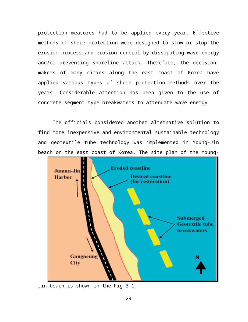
The officials considered another alternative solution to find more inexpensive and
environmental sustainable technology and geotextile tube technology was implemented in
Young-Jin beach on the east coast of Korea. The site plan of the Young-Jin beach is shown
in the Fig 3.1.
Fig 3.1 Site plan of Young-Jin beach (Shin and Oh, 2007).
21

3.1.2 2-D hydraulic stability analysis
2-D hydraulic stability analysis results are shown in figures 3.2, 3.3and 3.4. The
geometry of the geotextile tube, the characteristics of the filling material, and the base soil
properties are the same as the field conditions at Young-Jin beach (Shin and Oh, 2007). The
variable parameters of the stability analysis are the filling ratio and the significant wave
height. They were varied from 85% to 95% and from 1.0 to 5.0m respectively. From the
results of 2-D stability analysis, the safety factor is decreased on increasing the filling ratio
and significant wave height. However the safety factors of sliding and overturning vary
exponentially. Also, the double lined tube is found to be more stable than single installed
tube.
Fig 3.2 SF of sliding (Shin and Oh, 2007).
22

Fig 3.3 SF of overturning (Shin and Oh, 2007).
Fig 3.4 SF of bearing capacity failure (Shin and Oh, 2007).
23

3.1.3 Design and construction
It was determined that two lines geotextile tube could be used at the Young-Jin
beach. For shoreline protection the geotextile tube was installed 1m below the water surface
and as deep as possible, firstly to avoid spoiling the scenery and secondly to reduce the
navigational risks. Geotextile tubes were designed two lines as detached breakwaters and
had to be installed in about 3.0m of water, 90-100m distant from the shoreline. A single
detached breakwater element implemented as a geotextile tube had a circumference 9.5m,
50m long and the effective height was 1.8m. It covered 240m of near shore along the
shoreline of Young-Jin beach (Shin and Oh, 2006).
The apron mat was installed as a fabric blanket to protect against scouring. The edge
of the fabric was folded back 0.5m and sewn forming a small tube that could be filled with
sand. These small tubes help anchor the scour blanket. A cutter section dredging ship was
used to fill the geotextile tubes and the large barge ship was used in the whole construction
process. Also special hardwares were required to connect the dredge discharge pipe to the
tube.
3.1.4 Installation
A total of eight geotextile tubes were installed at the Young-Jin cove. The shoreline
variation and water depth of the offshore area were also monitored (Shin and Oh, 2007).
Four of the two lines geotextile tubes were installed from south to north, spaced at 20.0m
intervals. The installation procedure involved:
Surveying the installation point
Installing the apron mat
Placing the geotextile tube
Connecting the injection nozzle and port of the tube
Dredging and filling the tube with soil
Checking the effective height
Completing the dredging and filling operation
24

Before and during the hydraulic filling, the pumping pressure, speed and mixing
ratio of slurry were varied to determine the optimum value.
3.1.5 Observation after construction
Observations of the filling process show that settling and drainage occurred very fast.
The construction of one geotextile tube requires less than 1 hour and the desired final height
was achieved after only four dredging and filling steps. After 1 year in use, seaweed had
inhabited the surface of the submerged tube (Fig 3.5). Hence it can be concluded that the
polymer material used in their manufacture is unlikely to have an adverse effect on marine
life (Shin and Oh, 2007). Moreover, it can be environmentally sustainable to the adjacent
ecology. The test sites have been exposed to a number of severe storms common to the east
coast of Korea. This makes it difficult to evaluate the structures performance as a form of
innovative shore protection.
Over the short period of four observations, the variation of shoreline with the elapsed
time was extended into the sea during 3 months, because of the short term effectiveness of
wave absorption and decrement of sea bed soil migration. After 3 months however the
shoreline was re-eroded by tidal waves and geometrical reason. However the magnitude of
the re-erosion was relatively small compared to the extension of the shoreline. The water
depth in the near shore area decreased with elapsed time, and the sand gradually
accumulated around areas covered by the geotextile tube (Fig 3.6).
Fig 3.5 Tubes covered by seaweed (Shin and Oh, 2007).
25

Fig 3.6 Sand accumulation by geotextile tube (Shin and Oh, 2007).
3.2 COASTAL EROSION PREVENTION MEASURES AT A BEACH IN MEXICO
A particularity of this beach system is that there are not many natural sediment
sources such as river discharges, so littoral balance may be easily broken by infrastructure
such as small harbors, piers and groins. The first attempts to control beach erosion were
individual actions undertaken to retain sediment for beach stabilization without considering
the consequences along the coast. By the end of 2002, the situation was critical, since many
beaches were almost fully eroded and risk of destruction due to extreme waves induced by
any hurricane with a path through the Gulf of Mexico was permanent.
The combination of wave climate, currents, tides and storm surges is the main cause
of beach erosion. Based on local experience in the past 20 years, any beach restoration
action has to be environmentally friendly and also it needs to consider possible negative
impact on adjacent beaches (Alvarez et al. 2007). Among the various alternatives for
submerged structures, geotextile tubes were chosen for their viability to cause wave
dissipation. The low costs for initial installation and maintenance, were also considered.
Geotextiles were installed upto a length of 4km in Yucatan. The geotextile tube cross-
section provided was as shown in Fig 3.7.
26
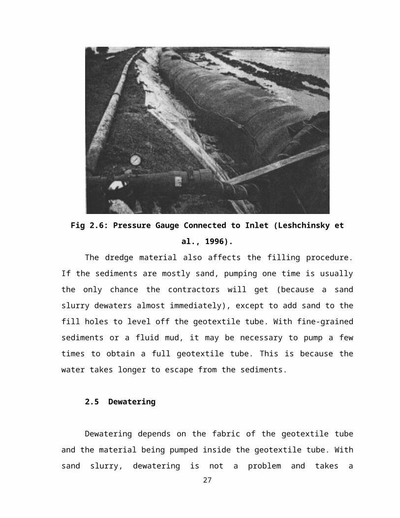
Fig 3.7 Geotextile tube cross-section (Alvarez et al. 2007).
Fig 3.8 Geotextile tube inducing wave breaking for energy attenuation (Alvarez et al.
2007).
27

Fig 3.9 Wave breaking process in (b) middle–high tide and (c) low-tide conditions
(Alvarez et al. 2007).
The geotextile tubes were installed along the shoreline and after 18 months of
monitoring they have been performing satisfactorily as parallel submerged breakwaters (Fig
3.8 and 3.9). The energy dissipation was generated by wave breaking due to the presence of
tubes. Efficiency of design depends highly on how precise is the evaluation of wave
transmission at the geotextile tubes. The tensile strength for geosynthetics is conditioned
mainly by slurry-pumping pressure. Most of the tubes were filled with pumping equipment
from island and offshore sediments banks, with no overstressed geotextiles detected.
4. SUMMARY AND CONCLUSIONS
Geotextiles are being used for a variety of Civil Engineering applications. One such
application being the use of geotextiles for coastal erosion prevention. Shore erosion is
currently causing millions of dollars worth of damage to our shorelines. Because of the
shortage of natural rock, the materials used in hydraulic and coastal structures are changing
from traditional rubble and concrete systems to cheaper materials and systems. One of the
methods for coastal erosion prevention is to employ geotextile tube technology in the
construction of shore protection structures. Recently, geotextile tube technology has
advanced to become the most effective solution of choice.
28
The design considerations, hydraulic stability analysis and the installation of
geotextile tubes have been explained in this report. Further two case studies dealing with
coastal erosion prevention by geotextile tube technology have been discussed. The following
are the major conclusions reported:
1. Geotextile tubes performing as shore parallel low-crested structures have shown that
they are an effective and environmentally friendly alternative for shore stabilization.
2. 2-D hydraulic stability analysis conducted with reference to the field conditions at
Young-Jin beach indicated that:
The safety factor is decreased on increasing the filling ratio and significant wave
height.
The safety factor of bearing capacity varies linearly with filling ratio and significant
wave height. However, the safety factors of sliding and overturning vary
exponentially.
Also it was found that double-lined tube is more stable than single installed tube.
REFERENCES
1. Shin, E.C. and Oh, Y.I., (2006), “Using submerged geotextile tubes in the protection of
E. Korean shore”, Coastal engineering, Vol. 53, pp. 879-895.
2. Alvarez, I.E. and Rubio, R., Ricalde, H., (2007), “Beach restoration with geotextile tubes
as submerged breakwaters in Yucatan, Mexico”, Geotextiles and Geomembranes, Vol.
22, pp. 233-241.
3. Shin, E.C. and Oh, Y.I., (2007), “Coastal erosion prevention by geotextile tube
technology”, Geotextiles and Geomembranes, Vol. 25, pp. 264-277.
4. Koffler, A., Choura, M., Bendriss, A. and Zengerink, E., (2008), “Geosynthetics against
protection against erosion for river and coastal banks and marine and hydraulic
construction”, Journal of coastal conservation, Vol. 12, pp. 11-17.
29