Coal-Fired Power Plant Heat Rate Reductions
48
COAL-FIRED POWER PLANT HEAT RATE REDUCTIONS SL-009597 FINAL REPORT JANUARY 22, 2009 PROJECT 12301-001 PREPARED BY 55 East Monroe Street • Chicago, IL 60603-5780 USA • 312-269-2000 www.sargentlundy.com
-
Upload
pangerankacang -
Category
Documents
-
view
82 -
download
6
description
Heat Rate Reduction
Transcript of Coal-Fired Power Plant Heat Rate Reductions
COAL-FIRED POWER PLANT HEAT RATE REDUCTIONS
SL-009597FINAL REPORT
JANUARY 22, 2009PROJECT 12301-001
PREPARED BY
55 East Monroe Street • Chicago, IL 60603-5780 USA • 312-269-2000 www.sargentlundy.com
LEGAL NOTICE This report was prepared by Sargent & Lundy, L.L.C., hereinafter referred to as S&L, expressly for Perrin Quarles Associates,
Inc., hereinafter referred to as PQA, under EPA Contract No. EP-W-07-064. Neither S&L nor any person acting on its behalf
(a) makes any warranty, express or implied, with respect to the use of any information or methods disclosed in this report or
(b) assumes any liability with respect to the use of any information or methods disclosed in this report. Although prepared with
EPA funding and reviewed by the EPA, this report has not been approved by the EPA for publication as an EPA report. The
contents do not necessarily reflect the views or policies of the EPA, nor does mention of trade names or commercial products
constitute endorsement or recommendation for use.
iCOAL-FIRED POWER PLANT HEAT RATE REDUCTIONS SL-009597 Final Report
CONTENTS Section Page
SL-009597 PQA_SL_EPA_ Final.doc Project 12301-001
1. INTRODUCTION ...................................................................................................................................1-1 1.1 PURPOSE ........................................................................................................................................................ 1-1 1.2 STUDY SCOPE ................................................................................................................................................ 1-1
2. BOILER ISLAND ...................................................................................................................................2-1 2.1 MATERIALS HANDLING................................................................................................................................. 2-1 2.2 BOILER OPERATION/OVERHAUL WITH NEW HEAT TRANSFER SURFACE ..................................................... 2-2 2.3 NEURAL NETWORK ....................................................................................................................................... 2-3 2.4 INTELLIGENT SOOTBLOWERS ........................................................................................................................ 2-5 2.5 AIR HEATERS................................................................................................................................................. 2-6
2.5.1 Limit Air Heater Leakage...................................................................................................................... 2-6 2.5.2 Lower Air Heater Outlet Temperature by Controlling Acid Dew Point ............................................... 2-8
3. TURBINE ISLAND .................................................................................................................................3-1 3.1 TURBINE OVERHAUL..................................................................................................................................... 3-1 3.2 FEEDWATER HEATERS................................................................................................................................... 3-2 3.3 CONDENSER................................................................................................................................................... 3-3 3.4 BOILER FEED PUMPS ..................................................................................................................................... 3-4
4. FLUE GAS SYSTEM..............................................................................................................................4-1 4.1 ID FANS......................................................................................................................................................... 4-1 4.2 VARIABLE-FREQUENCY DRIVES ................................................................................................................... 4-3
5. EMISSIONS CONTROL TECHNOLOGIES ..............................................................................................5-1 5.1 FGD SYSTEM................................................................................................................................................. 5-1
5.1.1 Removal of Venturi Throat ................................................................................................................... 5-2 5.1.2 Addition of Turning Vanes/Perforated Gas Distribution Plates............................................................ 5-2 5.1.3 Shutoff Spray Level .............................................................................................................................. 5-3 5.1.4 Variable-Frequency Drives ................................................................................................................... 5-3
5.2 PARTICULATE CONTROL SYSTEM.................................................................................................................. 5-4 5.3 SCR SYSTEM ................................................................................................................................................. 5-6
iiCOAL-FIRED POWER PLANT HEAT RATE REDUCTIONS SL-009597 Final Report
CONTENTS Section Page
SL-009597 PQA_SL_EPA_ Final.doc Project 12301-001
6. WATER TREATMENT SYSTEM ............................................................................................................6-1 6.1 BOILER WATER TREATMENT ........................................................................................................................ 6-1 6.2 COOLING WATER TREATMENT ..................................................................................................................... 6-2 6.3 ADVANCED COOLING TOWER PACKING ....................................................................................................... 6-3
7. OTHER POTENTIAL IMPROVEMENTS .................................................................................................7-1
8. CASE STUDIES .....................................................................................................................................8-1 8.1 250-MW PC PLANT ...................................................................................................................................... 8-1 8.2 850-MW PC PLANT WITH FGD AND BAGHOUSE ......................................................................................... 8-3 8.3 AXIAL FANS VERSUS CENTRIFUGAL FANS ................................................................................................... 8-4
9. REFERENCES .......................................................................................................................................9-1 9.1 TECHNOLOGY VENDORS ............................................................................................................................... 9-1 9.2 SURVEYED LITERATURE................................................................................................................................ 9-1
iiiCOAL-FIRED POWER PLANT HEAT RATE REDUCTIONS SL-009597 Final Report
FIGURE AND TABLES No. Page
SL-009597 PQA_SL_EPA_ Final.doc Project 12301-001
Figure 5-1. Spark Generation Profile ..........................................................................................................................................5-5
Table 2-1. Summary of Economizer Heat Rate Reductions and Costs .......................................................................................2-3 Table 2-2. Summary of NN Heat Rate Reductions and Costs.....................................................................................................2-5 Table 2-3. Summary of ISB Heat Rate Reductions and Costs ....................................................................................................2-6 Table 2-4. Summary of Air Heater and Duct Leakage Control Heat Rate Reductions and Costs ..............................................2-8 Table 2-5. Summary of Acid Dew Point Control Heat Rate Reductions and Costs ...................................................................2-8 Table 3-1. Summary of Turbine Overhaul Heat Rate Reductions and Costs..............................................................................3-2 Table 3-2. Summary of Condenser Heat Rate Reductions and Costs .........................................................................................3-4 Table 3-3. Summary of Boiler Feed Pump Heat Rate Reductions and Costs .............................................................................3-5 Table 4-1. Summary of ID Axial Fan (and Motor) Heat Rate Reductions and Costs .................................................................4-2 Table 4-2. Summary of VFD (only) Heat Rate Reductions and Costs........................................................................................4-3 Table 4-3. Summary of Combined VFD and Fan Heat Rate Reductions and Costs ...................................................................4-4 Table 5-1. Summary of FGD System Modification Heat Rate Reductions and Costs ................................................................5-4 Table 5-2. Summary of ESP Modification Heat Rate Reductions and Costs..............................................................................5-6 Table 5-3. Summary of SCR System Modification Heat Rate Reductions and Costs ................................................................5-6 Table 5-4. Summary of Combined Environmental Controls Technology Heat Rate Reductions and Costs ..............................5-7 Table 6-1. Summary of Cooling Tower Advanced Packing Upgrade, Heat Rate Reductions and Costs ...................................6-4 Table 7-1. Summary of Motor Efficiency Heat Rate Reductions ...............................................................................................7-1 Table 8-1. Summary of 250-MW Unit Heat Rate Reductions and Costs....................................................................................8-3 Table 8-2. Summary of 850-MW Unit Heat Rate Reductions and Costs....................................................................................8-4 Table 8-3. Summary of Fan Heat Rate Reductions and Costs ....................................................................................................8-5

1-1COAL-FIRED POWER PLANT HEAT RATE REDUCTIONS SL-009597 Final Report
SL-009597 PQA_SL_EPA_ Final.doc Project 12301-001
1. INTRODUCTION
1.1 PURPOSE
On behalf of Perrin Quarles Associates, Inc. (PQA), Sargent & Lundy, L.L.C. (S&L) performed a study of various
methods to reduce the heat rate of existing U.S. coal-fired power plants in a range of sizes−200 MW, 500 MW, and
900 MW. The primary intent of the study was to focus on methods that have been successfully implemented by the
utility industry.
The heat rate of a plant is the amount of fuel energy input needed (Btu, higher heating value basis) to produce
1 kWh of net electrical energy output. It is the metric most often used in the electric power generation industry to
track and report the performance of thermal power plants. The average, annual operating heat rate of U.S. coal-fired
power plants is approximately 10,400 Btu/kWh. The design heat rate of a facility is based on full-load operation
with no boiler blowdown, whereas most reported heat rates of operating facilities include performance during off-
peak loads and include boiler blowdown. Because operating units report heat rates that include performance at all
levels, the numbers are usually significantly higher than the design heat rate.
This study identifies specific plant systems and equipment where efficiency improvements can be realized either
through new installations or modifications, and provides estimates of the resulting net plant heat rate reductions and
the order-of-magnitude costs for implementation. To conduct the study presented in this report, S&L surveyed
available literature, spoke with technology manufacturers, and used its engineering expertise as the basis.
1.2 STUDY SCOPE
The study scope encompassed the following major tasks:
• Discussion of methods to reduce the heat rate of existing power plants.
• Preparation of case studies quantifying heat rate reductions resulting from the methods described herein.
• Survey of existing plants and published literature to assess heat rate reductions typically achieved in the industry.
• Development of order-of-magnitude capital, fixed, and variable operations and maintenance (O&M) cost estimates for the modifications associated with the methods described for typical 200-, 500-, and 900-MW coal plants.
1-2COAL-FIRED POWER PLANT HEAT RATE REDUCTIONS SL-009597 Final Report
SL-009597 PQA_SL_EPA_ Final.doc Project 12301-001
−
−
−
−
−
−
−
−
−
−
−
This report addresses the following modifications:
• Major steam turbine modifications, such as replacement of rotors, blades, nozzles, seals and inner and outer casings.
• Major boiler modifications.
• Control systems (digital, online performance monitoring, etc.).
• High-efficiency motors on all major rotating equipment.
• Variable-frequency drive (VFD) motors on all major rotating equipment (usually improves efficiencies at lower than full load).
• Other modifications known to result in substantial equipment and system efficiency gains and plant heat rate reductions.
Based on the above scope, S&L divided the power plant into the following blocks and identified possible methods
for efficiency improvement and heat rate reductions in the following areas:
• Boiler island
Coal transport, conveying, and grinding
Boiler operation/overhaul with new heat transfer surface
Neural network (NN) control system
Intelligent sootblower (ISB) system
Air heater
• Turbine island
Turbine
Feedwater heater
Condenser
Turbine drive/motor-driven feed pump
• Flue gas system
Forced draft (FD) and induced draft (ID) fan improvement
Variable-frequency drive (VFD)
1-3COAL-FIRED POWER PLANT HEAT RATE REDUCTIONS SL-009597 Final Report
SL-009597 PQA_SL_EPA_ Final.doc Project 12301-001
−
−
−
−
−
• Air pollution control equipment
Flue gas desulfurization (FGD) system
Particulate system
Selective catalytic reduction (SCR) system
• Water treatment system
Boiler water treatment
Cooling tower
This report discusses potential efficiency improvement concepts and the resulting heat rate reductions that can be
implemented in various systems of a typical coal-fired power plant. All estimated capital and installation costs are
referenced from work in progress and vendor quotes as of the year 2008. The costs represent values of new
equipment purchased in the year 2008. S&L cautions that the costs presented herein are not indicative of those that
may be expected for a specific facility due to variables such as equipment, material, and labor market conditions
and site specifications. However, these cost estimates provide valuable information for comparative purposes when
evaluating the advantages and disadvantages of the various concepts. The costs should not be used as a basis for
project budgeting or financing purposes.
For budgeting or financing purposes, S&L recommends site-specific evaluations and cost analyses based on actual
market conditions for any and all required equipment, material, and labor at the time of the project.
2-1COAL-FIRED POWER PLANT HEAT RATE REDUCTIONS SL-009597 Final Report
SL-009597 PQA_SL_EPA_ Final.doc Project 12301-001
2. BOILER ISLAND
This section of the report discusses modifications to systems and equipment within the boiler island that offer
potential improvements in plant heat rate:
• Materials handling
• Boiler operation/overhaul with new heat transfer surface
• NN control system
• ISB system
• Air heaters
2.1 MATERIALS HANDLING
The coal handling portion of a power plant can encompass every piece of equipment from rail, truck, or barge
unloading to the conveyors, crushers, and storage bins. The equipment generally operates intermittently for a set
number of hours each day and does not consume a significant amount of energy. An estimated, typical power
requirement as a fraction of total gross power plant output is 0.07%. Improvements to the process efficiency are
limited primarily to the motors and drives. As the drives deteriorate in function and performance, they can be
replaced with more energy-efficient motors. Additionally, VFDs are already used for certain applications within the
coal handling equipment, but for reasons other than efficiency at low turndown. Specifically, VFDs are used to
reduce excess strains on equipment, such as belts and conveyors during startup, and their application for reducing
energy demands at turndown is not significantly applicable due to the intermittent operation of the coal handling
equipment. Although VFDs provide more precise control of the operating equipment, which can be considered an
efficiency improvement, the reduction in overall plant heat rate is not substantial.
Coal pulverizers are used to provide fine coal particles for pneumatic transport into the boiler for combustion. Fine
coal particles improve the combustion efficiency of a boiler. The improvement in combustion reduces the amount
of coal that must be transported and burned in the boiler and thereby reduces fuel cost and the plant heat rate.
Improvements to pulverizer designs have enabled more finely ground coal and a lower primary air pressure drop
through the pulverizer.Ref. 49 Such improvements can also be incorporated on older existing units, but may result in a
loss in mass throughput. This reduction in throughput is generally greater than the fuel use savings from enhanced
coal fineness, thereby reducing the capacity of the pulverizer. If a plant has excess pulverizer capacity, such
2-2COAL-FIRED POWER PLANT HEAT RATE REDUCTIONS SL-009597 Final Report
SL-009597 PQA_SL_EPA_ Final.doc Project 12301-001
improvements can be implemented. If the facility is switching fuels, then such upgrades are probably warranted.
But, based on historical projects, this area of improvement has not yielded significant reductions in plant heat rate
unless the machinery was severely degraded. The costs associated with such projects are significant.
The ash handling system presents some opportunities to switch from a water-sluicing bottom ash system to a dry
drag chain system, which can save some power and water for the plant. But, in general, ash handling equipment is
another area of material handling that does not present much opportunity to economically reduce auxiliary power
requirements. An average of the power consumed by ash handling equipment as a percentage of total gross plant
power consumption is 0.1%. The equipment operates intermittently, similar to the coal handling equipment and,
therefore, is not considered a prime area of investment for plant heat rate reduction.
2.2 BOILER OPERATION/OVERHAUL WITH NEW HEAT TRANSFER SURFACE
The furnace of a power plant is the most significant aspect of a facility affecting the thermal performance, aside
from the steam turbine generator. The design of furnaces in the 1950s through the 1970s typically was based on a
specific design fuel and the premise that it would operate at base load. Today’s competitive electric utility market
has required a number of facilities to begin operating units originally designed for base load as cycling units to
maximize profits. Additionally, replacement of the original design coal with lesser-valued fuels is more common
today to reduce operating costs and/or to economically meet environmental emissions requirements. These two
system changes have required major alterations to power plants in order to maintain the highest plant output and
lowest plant heat rate.Refs. , , 33 38 39
During the initial study phase in which a plant considers options for a fuel switch, it looks at many opportunities for
upgrading the furnace to enhance its efficiency in using an off-design fuel or fuel blend. These opportunities
generally entail the replacement of older equipment, piping, and headers with more advanced designs and materials
to improve the performance of the furnace. Additional tubing may also be added to increase the surface area for
either enhanced steam production or quality. However, if not properly designed, the changes to the boiler may
result in problems with the furnace such as: variances in radiant absorption and consequent overheating in certain
areas of the furnace, reduced steam flow or water circulation, flow instabilities, inefficient water-steam separation,
inefficient reheat temperatures, and ash and slag buildup, which may result in higher heat rates than estimated.
Generally, a plant makes incremental changes to a furnace to maintain the unit, but large investments, such as major
furnace upgrades are not undertaken solely for efficiency improvement and heat rate reduction purposes due to
regulations currently in place. Therefore for Owners seeking significant efficiency improvements with a power
2-3COAL-FIRED POWER PLANT HEAT RATE REDUCTIONS SL-009597 Final Report
SL-009597 PQA_SL_EPA_ Final.doc Project 12301-001
plant including the boiler, it is more economic to simply build a new, more efficient, power plant. For these
reasons, a potential reduction in heat rate was not included here for major boiler upgrades since such upgrades
generally occur during a fuel switch. Moreover, such upgrades entail entirely new design efficiencies for the
furnace because the new fuel is generally substantially different from the original design fuel. Therefore, a
comparison of before/after heat rates would not accurately represent a potential for heat rate reduction.
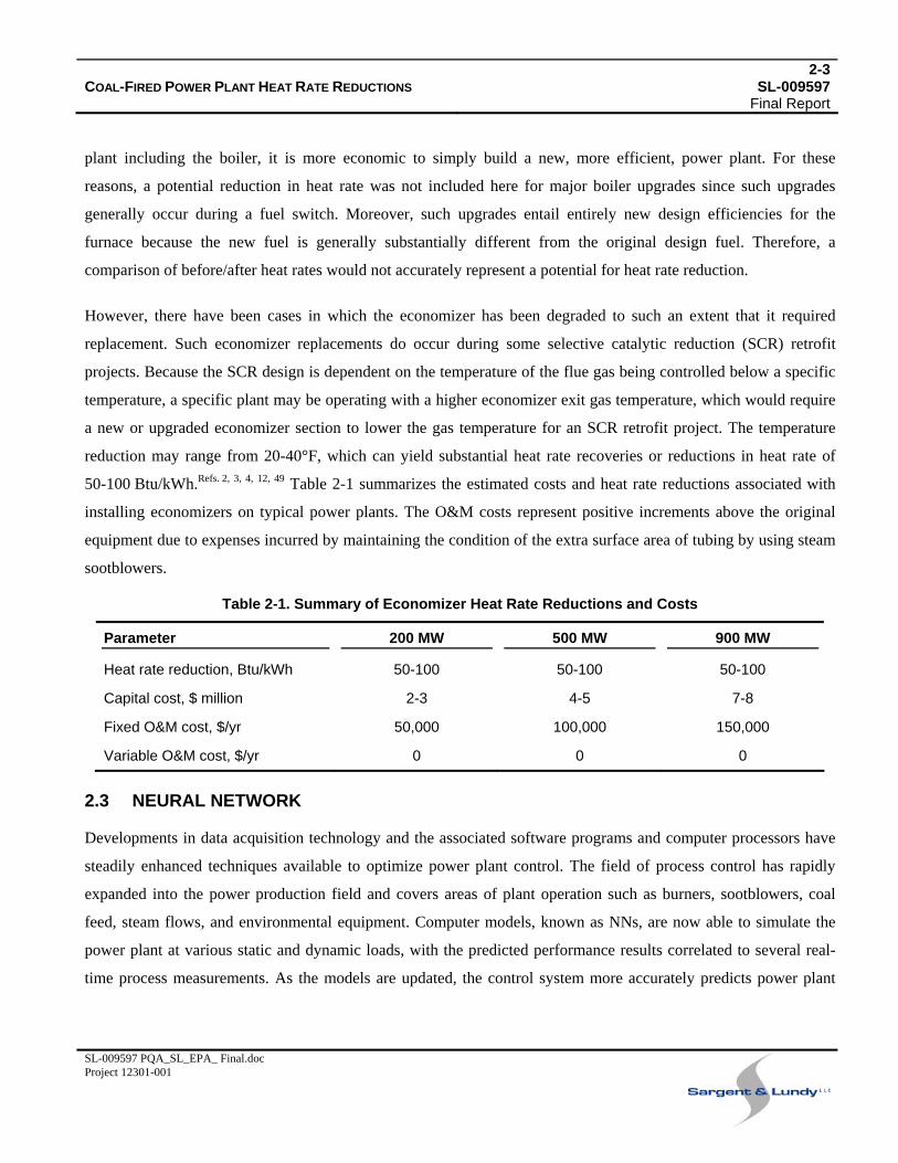
However, there have been cases in which the economizer has been degraded to such an extent that it required
replacement. Such economizer replacements do occur during some selective catalytic reduction (SCR) retrofit
projects. Because the SCR design is dependent on the temperature of the flue gas being controlled below a specific
temperature, a specific plant may be operating with a higher economizer exit gas temperature, which would require
a new or upgraded economizer section to lower the gas temperature for an SCR retrofit project. The temperature
reduction may range from 20-40°F, which can yield substantial heat rate recoveries or reductions in heat rate of
50-100 Btu/kWh.Refs. , , , , 2 3 4 12 49 Table 2-1 summarizes the estimated costs and heat rate reductions associated with
installing economizers on typical power plants. The O&M costs represent positive increments above the original
equipment due to expenses incurred by maintaining the condition of the extra surface area of tubing by using steam
sootblowers.
Table 2-1. Summary of Economizer Heat Rate Reductions and Costs
Parameter 200 MW 500 MW 900 MW
Heat rate reduction, Btu/kWh 50-100 50-100 50-100
Capital cost, $ million 2-3 4-5 7-8
Fixed O&M cost, $/yr 50,000 100,000 150,000
Variable O&M cost, $/yr 0 0 0
2.3 NEURAL NETWORK
Developments in data acquisition technology and the associated software programs and computer processors have
steadily enhanced techniques available to optimize power plant control. The field of process control has rapidly
expanded into the power production field and covers areas of plant operation such as burners, sootblowers, coal
feed, steam flows, and environmental equipment. Computer models, known as NNs, are now able to simulate the
power plant at various static and dynamic loads, with the predicted performance results correlated to several real-
time process measurements. As the models are updated, the control system more accurately predicts power plant
2-4COAL-FIRED POWER PLANT HEAT RATE REDUCTIONS SL-009597 Final Report
SL-009597 PQA_SL_EPA_ Final.doc Project 12301-001
performance during various load changes, improving overall efficiency and reducing detrimental conditions of
stress on the plant.
There are a number of NN systems offered by vendors in the industry. These systems basically operate in a similar
fashion but differ in terms of complexity. In general, an NN system ties into the distributed control system (DCS)
for data input and control and uses proprietary modeling and control modules that have been developed specifically
for the plant with operator input. NN systems have been installed on more than 300 boilers in the U.S., primarily
for burner optimization and NOX control and heat rate improvement. A specific application of the NN system
would be for combustion control to limit NOX and CO emissions. These emissions tend to increase as the plant
undergoes rapid load changes and it is this area of operation where model predictive control (MPC) modules
drastically improve plant emissions performance. Optical combustion monitoring systems often will help supply the
necessary information to the NN system and combustion optimization module to provide real-time, adaptive control
to prevent emissions spikes during load-following operation. Other areas of optimization include control of excess
O2, superheat and reheat steam temperatures, superheat and reheat steam spray flows, and operation of the SCR and
flue gas desulfurization (FGD) systems based on NOX and SO2 levels.
Controlling excessive superheat and reheat steam temperatures is of paramount importance in preventing
mechanical degradation of the boiler tubes. Similarly, excessive steam temperatures require tempering, which
reduces plant thermal performance. NN systems provide adaptive control modules to provide burner tilt and steam
tempering to properly balance plant steam response to load changes.
Depending on the complexity of the NN system applied and on the quality of DCS installed at a power plant, the
improvement in heat rate can be significant. The expected range of improvement in boiler efficiency is 0-1.5%pt.
Refs. , , , , , , , , , 9 16 18 26 27 34 38 44 52 53
The estimated capital cost to implement NN technology ranges from $500,000 to $750,000, depending on the
existing automation. Factors that can increase the cost of an NN system are the age and condition of the existing
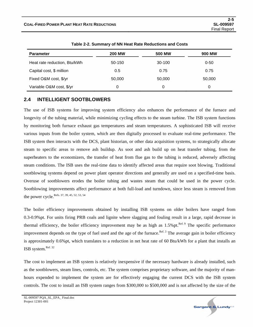
DCS. The cost includes hardware and installation time for the NN system only. Table 2-2 summarizes the NN heat
rate reductions and costs. The O&M expenditures are representative of software updates, onsite training, and
computer hardware replacement.
2-5COAL-FIRED POWER PLANT HEAT RATE REDUCTIONS SL-009597 Final Report
SL-009597 PQA_SL_EPA_ Final.doc Project 12301-001
Table 2-2. Summary of NN Heat Rate Reductions and Costs
Parameter 200 MW 500 MW 900 MW
Heat rate reduction, Btu/kWh 50-150 30-100 0-50
Capital cost, $ million 0.5 0.75 0.75
Fixed O&M cost, $/yr 50,000 50,000 50,000
Variable O&M cost, $/yr 0 0 0
2.4 INTELLIGENT SOOTBLOWERS
The use of ISB systems for improving system efficiency also enhances the performance of the furnace and
longevity of the tubing material, while minimizing cycling effects to the steam turbine. The ISB system functions
by monitoring both furnace exhaust gas temperatures and steam temperatures. A sophisticated ISB will receive
various inputs from the boiler system, which are then digitally processed to evaluate real-time performance. The
ISB system then interacts with the DCS, plant historian, or other data acquisition systems, to strategically allocate
steam to specific areas to remove ash buildup. As soot and ash build up on heat transfer tubing, from the
superheaters to the economizers, the transfer of heat from flue gas to the tubing is reduced, adversely affecting
steam conditions. The ISB uses the real-time data to identify affected areas that require soot blowing. Traditional
sootblowing systems depend on power plant operator directions and generally are used on a specified-time basis.
Overuse of sootblowers erodes the boiler tubing and wastes steam that could be used in the power cycle.
Sootblowing improvements affect performance at both full-load and turndown, since less steam is removed from
the power cycle.Refs. , , , , , 37 39 45 52 53 54
The boiler efficiency improvements obtained by installing ISB systems on older boilers have ranged from
0.3-0.9%pt. For units firing PRB coals and lignite where slagging and fouling result in a large, rapid decrease in
thermal efficiency, the boiler efficiency improvement may be as high as 1.5%pt.Ref. 9 The specific performance
improvement depends on the type of fuel used and the age of the furnace.Ref. 3 The average gain in boiler efficiency
is approximately 0.6%pt, which translates to a reduction in net heat rate of 60 Btu/kWh for a plant that installs an
ISB system.Ref. 32
The cost to implement an ISB system is relatively inexpensive if the necessary hardware is already installed, such
as the sootblowers, steam lines, controls, etc. The system comprises proprietary software, and the majority of man-
hours expended to implement the system are for effectively engaging the current DCS with the ISB system
controls. The cost to install an ISB system ranges from $300,000 to $500,000 and is not affected by the size of the
2-6COAL-FIRED POWER PLANT HEAT RATE REDUCTIONS SL-009597 Final Report
SL-009597 PQA_SL_EPA_ Final.doc Project 12301-001
boiler unit. The annual operating cost would be approximately $50,000. The separate improvements obtained via
NN and ISB systems are not necessarily cumulative. The overall improvement via either system could be nearly the
same as that achieved by the use of an advanced NN system integrated with an ISB system. The O&M expenditures
are representative of software updates, onsite training, and computer hardware replacement.
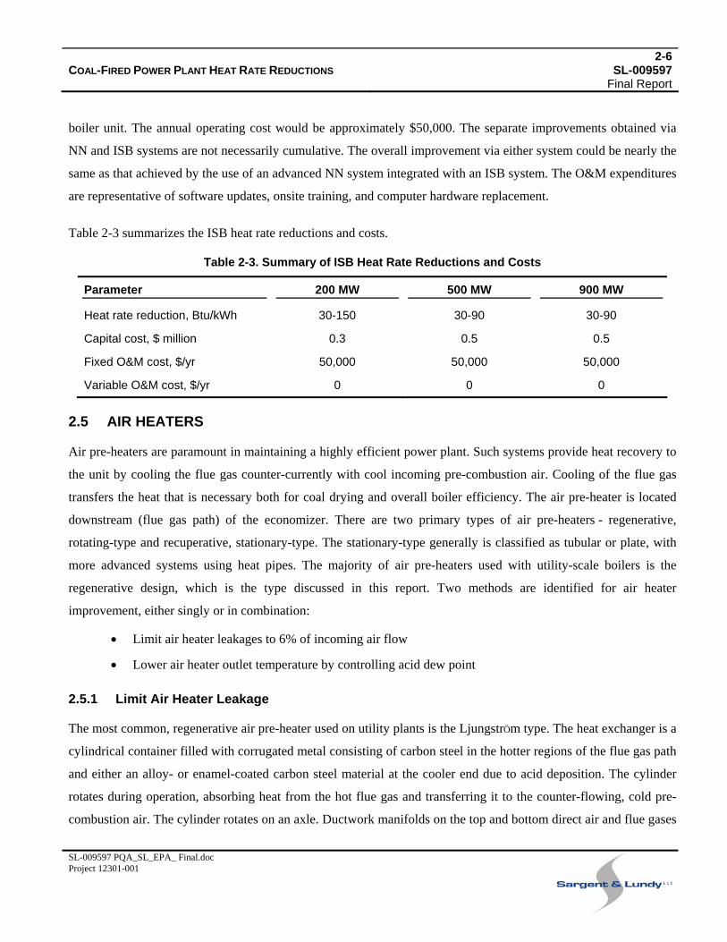
Table 2-3 summarizes the ISB heat rate reductions and costs.
Table 2-3. Summary of ISB Heat Rate Reductions and Costs
Parameter 200 MW 500 MW 900 MW
Heat rate reduction, Btu/kWh 30-150 30-90 30-90
Capital cost, $ million 0.3 0.5 0.5
Fixed O&M cost, $/yr 50,000 50,000 50,000
Variable O&M cost, $/yr 0 0 0
2.5 AIR HEATERS
Air pre-heaters are paramount in maintaining a highly efficient power plant. Such systems provide heat recovery to
the unit by cooling the flue gas counter-currently with cool incoming pre-combustion air. Cooling of the flue gas
transfers the heat that is necessary both for coal drying and overall boiler efficiency. The air pre-heater is located
downstream (flue gas path) of the economizer. There are two primary types of air pre-heaters - regenerative,
rotating-type and recuperative, stationary-type. The stationary-type generally is classified as tubular or plate, with
more advanced systems using heat pipes. The majority of air pre-heaters used with utility-scale boilers is the
regenerative design, which is the type discussed in this report. Two methods are identified for air heater
improvement, either singly or in combination:
• Limit air heater leakages to 6% of incoming air flow
• Lower air heater outlet temperature by controlling acid dew point
2.5.1 Limit Air Heater Leakage
The most common, regenerative air pre-heater used on utility plants is the LjungstrÖm type. The heat exchanger is a
cylindrical container filled with corrugated metal consisting of carbon steel in the hotter regions of the flue gas path
and either an alloy- or enamel-coated carbon steel material at the cooler end due to acid deposition. The cylinder
rotates during operation, absorbing heat from the hot flue gas and transferring it to the counter-flowing, cold pre-
combustion air. The cylinder rotates on an axle. Ductwork manifolds on the top and bottom direct air and flue gases

2-7COAL-FIRED POWER PLANT HEAT RATE REDUCTIONS SL-009597 Final Report
SL-009597 PQA_SL_EPA_ Final.doc Project 12301-001
into separate portions of the cylinder. A major difficulty associated with the use of regenerative air pre-heaters is air
leakage from the higher-pressure pre-combustion air side to the flue gas side.Ref. 49 Generally, the combustion air
leaks across the faces of the rotating section, thus bypassing the boiler and flowing out on the flue gas side. A
second area of air leakage is around the outer perimeter of the cylinder.Refs. , 36 49 Leakage affects boiler efficiency
due to lost heat recuperation. Fans are affected by the leakage since the combustion air requirement is fixed and any
leakage requires additional fan capacity. The forced draft (FD) and induced draft (ID) fan must operate at higher
capacities due to the increased flow incurred by the air bypassing the furnace.
Commissioning of air pre-heaters generally results in air leakage from the combustion air side to the flue gas side in
the range of 5-15%, with the higher percentages representative of older style air heaters. As a unit ages, the
percentage of air leaking past the seals increases, which lowers the plant efficiency due to the increase of air flow
sent through the FD fans to maintain sufficient O2 levels in the boiler. The increased air flow raises the auxiliary
power consumption of the FD fan; and if ID fans are used, even more auxiliary power is required to transfer the
extra air through the flue gas ductwork, emissions control equipment, and stack. Air leakage measurements are
difficult to accurately quantify and usually underestimate the actual leakage rate due to improperly located flow
sensors. The effects of air pre-heater leakage are evident in the loads on the fans as compared to the original design
loads if all other leakages are taken into account.
Regulatory mandates to retrofit existing units with environmental controls such as SCR, FGD, or baghouses, have
increased the auxiliary power needed to force the boiler flue gas through the added ductwork and emissions control
equipment. The increased fan power generally requires a booster fan to be installed or possibly new ID fans if the
plant does not already have an existing FGD system. If the air pre-heater allows a substantial amount of leakage
and that is not addressed, the extra gas flow will increase the power consumption of either the new ID fans or
booster fan more than necessary.
Improvements to seals on regenerative air pre-heaters have enabled the reduction of air leakage to roughly
6%.Ref. , 2 11 The improved seals offered by vendors are applied to the sectors, outer perimeter, and rotor section. The
range of heat rate reductions that may be achieved by reducing air heater leakage varies significantly from unit to
unit, but is approximately 10-40 Btu/kWh. If substantial improvements to a unit are implemented that include new
environmental control technology, which results in an increase in flue gas pressure drop, then reducing the air
heater leakage can decrease the plant heat rate by even more.Refs. , , , , 29 30 40 41 43
2-8COAL-FIRED POWER PLANT HEAT RATE REDUCTIONS SL-009597 Final Report
SL-009597 PQA_SL_EPA_ Final.doc Project 12301-001
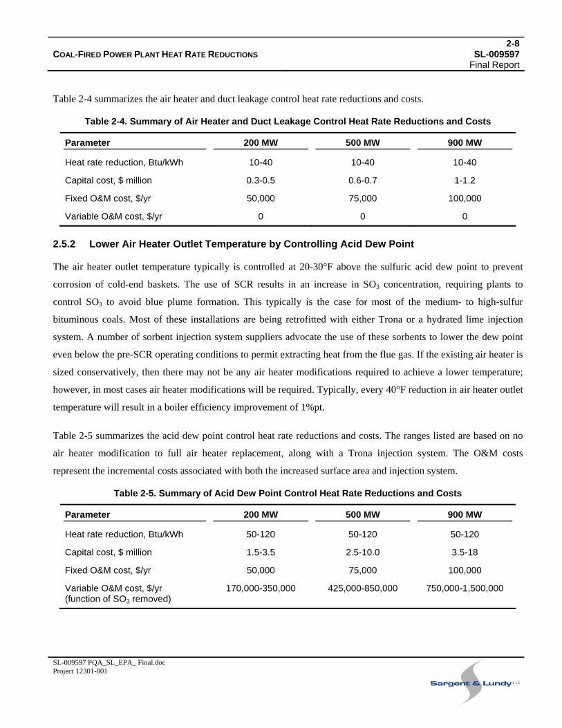
Table 2-4 summarizes the air heater and duct leakage control heat rate reductions and costs.
Table 2-4. Summary of Air Heater and Duct Leakage Control Heat Rate Reductions and Costs
Parameter 200 MW 500 MW 900 MW
Heat rate reduction, Btu/kWh 10-40 10-40 10-40
Capital cost, $ million 0.3-0.5 0.6-0.7 1-1.2
Fixed O&M cost, $/yr 50,000 75,000 100,000
Variable O&M cost, $/yr 0 0 0
2.5.2 Lower Air Heater Outlet Temperature by Controlling Acid Dew Point
The air heater outlet temperature typically is controlled at 20-30°F above the sulfuric acid dew point to prevent
corrosion of cold-end baskets. The use of SCR results in an increase in SO3 concentration, requiring plants to
control SO3 to avoid blue plume formation. This typically is the case for most of the medium- to high-sulfur
bituminous coals. Most of these installations are being retrofitted with either Trona or a hydrated lime injection
system. A number of sorbent injection system suppliers advocate the use of these sorbents to lower the dew point
even below the pre-SCR operating conditions to permit extracting heat from the flue gas. If the existing air heater is
sized conservatively, then there may not be any air heater modifications required to achieve a lower temperature;
however, in most cases air heater modifications will be required. Typically, every 40°F reduction in air heater outlet
temperature will result in a boiler efficiency improvement of 1%pt.
Table 2-5 summarizes the acid dew point control heat rate reductions and costs. The ranges listed are based on no
air heater modification to full air heater replacement, along with a Trona injection system. The O&M costs
represent the incremental costs associated with both the increased surface area and injection system.
Table 2-5. Summary of Acid Dew Point Control Heat Rate Reductions and Costs
Parameter 200 MW 500 MW 900 MW
Heat rate reduction, Btu/kWh 50-120 50-120 50-120
Capital cost, $ million 1.5-3.5 2.5-10.0 3.5-18
Fixed O&M cost, $/yr 50,000 75,000 100,000
Variable O&M cost, $/yr (function of SO3 removed)
170,000-350,000 425,000-850,000 750,000-1,500,000
3-1COAL-FIRED POWER PLANT HEAT RATE REDUCTIONS SL-009597 Final Report
SL-009597 PQA_SL_EPA_ Final.doc Project 12301-001
3. TURBINE ISLAND
This section of the report discusses modifications to systems and equipment within the turbine island that offer
potential reductions in plant heat rate:
• Turbine overhaul
• Feedwater heaters
• Condenser
• Turbine drive/motor-driven feed pumps
3.1 TURBINE OVERHAUL
Technological advancements have improved the efficiency and longevity of steam turbines. Advanced design tools,
such as computational fluid dynamics (CFD), have significantly enhanced turbine designer capabilities to increase
the efficiency of turbines. Additionally, development of materials with improved properties has enabled the
implementation of more efficient designs through fabrication of more geometrically complex components. The
improved turbine components have also provided a means to increase the efficiency of older turbines that are less
efficient and have experienced losses in performance due to degradation.Refs. , , , , , , , , 19 21 23 31 33 35 47 48 50
The greatest amount of improvement would be achieved from upgrading a turbine that has experienced significant
deterioration and has performed well below the design level. Significant increases in performance can be gained
from turbine upgrades when plants experience problems such as steam leakages or blade erosion. In such cases,
except for the outer casing, the entire turbine might have to be replaced, which would yield improvements in
turbine efficiency above 5%pt and, in extreme cases, can be over 10%pt. Such large improvements (>10%pt) in
efficiencies are not the norm in the industry.
The typical turbine upgrade depends on the case history of the turbine itself and its overall performance. The
upgrade can entail myriad improvements, all of which affect the performance and associated costs. For the average
unit that has undergone an upgrade, and is approximately 500-MW and 30 years old, the typical performance
improvements of the high-pressure (HP) and low-pressure (LP) units range from 2-3%pt and the intermediate-
pressure (IP) units range from 1-2%pt, totaling 2-3% in overall power generation. These upgrades take into account
the loss in performance over time (degradation). If the improvements are compared with the original design basis,
3-2COAL-FIRED POWER PLANT HEAT RATE REDUCTIONS SL-009597 Final Report
SL-009597 PQA_SL_EPA_ Final.doc Project 12301-001
they generally range from 1-2%pt for the HP and LP units and 1%pt for the IP units, totaling 1-2%pt in overall
power generation.Refs. , , , 2 6 14 21
In general, there have been few retrofits of small units, mainly due to the costs involved. However, benefits similar
to those achieved for large turbines (>500 MW) would be expected.
Table 3-1 summarizes the turbine overhaul heat rate reductions and costs. The heat rate reductions listed are a
function of their associated costs and represent the most realistic values that utilities have been willing to consider.
Future upgrades may be more extensive due to the current lack of new construction and the delays inherent in
obtaining new construction permits.
Table 3-1. Summary of Turbine Overhaul Heat Rate Reductions and Costs
Parameter 200 MW 500 MW 900 MW
Heat rate reduction, Btu/kWh 100-300 100-300 100-300
Capital cost, $ million 2-12 4-20 5-25
Fixed O&M cost, $/yr 0 0 0
Variable O&M cost, $/yr 0 0 0
3.2 FEEDWATER HEATERS
Feedwater heaters are used within a power plant’s thermal cycle to improve overall efficiency. The number and
placement of feedwater heaters are determined during the original plant design and are highly integrated with the
overall performance of the steam turbine. Feedwater heaters preheat the boiler feedwater prior to it entering the
boiler for steam generation. The heat used to increase the feedwater temperature comes directly from the thermal
cycle, as steam extracted from various turbine sections.
The feedwater heaters in a power plant are either LP or HP shell and tube heat exchangers. From an efficiency
standpoint, the primary means of improving the operation of such heat exchangers is to maintain their operational
effectiveness. Feedwater heating surface could be added to improve efficiency. However, the costs associated with
either increasing the heat transfer surfaces of existing heaters, or adding additional heaters for efficiency purposes
only, is prohibitive due to the small incremental reductions in heat rate that would be obtained.
3-3COAL-FIRED POWER PLANT HEAT RATE REDUCTIONS SL-009597 Final Report
SL-009597 PQA_SL_EPA_ Final.doc Project 12301-001
3.3 CONDENSER
Effective operation of the steam surface condenser in a power plant can significantly improve the heat rate of a unit.
In fact, in many cases it can pose the most significant hindrance to a plant trying to maintain its original design heat
rate. Since the primary function of the condenser is to condense steam flowing from the last stage of the steam
turbine to liquid form, it is most desirable from a thermodynamic standpoint that this occurs at the lowest
temperature reasonably feasible. By lowering the condensing temperature, the backpressure on the turbine is
lowered, which improves turbine performance. A condenser degrades primarily due to fouling of the tubes and air
in-leakage. Tube fouling leads to reduced heat transfer rates, while air in-leakage directly increases the
backpressure of the condenser and degrades the quality of the water. If once-through cooling is used, fouling of
condenser tubing can be substantial. But if a closed cooling system is used, cooling water quality can be controlled
to a much higher degree.
Condenser tube cleaning can be performed while the unit is on line or off line. Generally, the historical standard
method of online cleaning has been to use circulating rubber sponge balls that flow through the condenser tubes
with the coolant. Frictional contact between the balls and tubing scrapes away most of the fouling accumulated on
the inside of the tubes. The balls are circulated through the condenser for a few hours each day.
Because the use of sponge balls for cleaning condensers can involve adverse side effects, such as the plugging and
erosion of the tubing (especially on older condensers), the method is not always practical for all power plants due to
the type of fouling that may be occurring. Furthermore, if a plant does not have adequate personnel to properly
maintain the cleaning system, it may be removed in some cases. If a plant’s condenser cooling system was not
originally designed with a sponge ball system, then installing a new cleaning system can be very costly compared
to other alternatives. Under these circumstances, a plant may find that installing a new condenser is financially
warranted. Today’s condensers are designed more efficiently to reduce circulating water pressure drop and to
enhance the cooling and condensing of the steam turbine exhaust. The materials of construction are more resilient
towards erosion from cleaning and corrosion. Additionally, the newly designed condensers can reduce stress
induced failure due to cycling service.
The offline or reduced-load cleaning method that is most effective uses manual techniques involving brushes, HP
water lances, or projectile cleaners (metal pigs or “cleaners”). The metal cleaners are forced through tubes with
pressurized water (~300 psig) to scrape away deposits by frictional contact. Plastic cleaners are not as effective as
metal cleaners, and a cleaning regime using both methods may be applied. Metal cleaners tend to produce the best
3-4COAL-FIRED POWER PLANT HEAT RATE REDUCTIONS SL-009597 Final Report
SL-009597 PQA_SL_EPA_ Final.doc Project 12301-001
results, but this can depend on the specific type of fouling. This mechanical cleaning method can improve heat
transfer rates in the condenser to near-design values and substantially improve condenser backpressure. Metal
brushes unfortunately tend to erode the tubing, but plastic brushes can be used instead. Mechanical cleaning can be
performed on line but at reduced load depending on the condenser arrangement. If this is not feasible, the unit must
be taken off line for condenser cleaning.Refs. , , 5 42 46
Brush cleaning can improve the condenser backpressure by approximately 0.1 in. Hg and a mechanical cleaning
can improve it by as much as 0.6 in. Hg or more. An average cleaning schedule that is properly implemented can
reduce the backpressure on a once-through condenser by about 0.35 in. Hg, resulting in heat rate reduction of
approximately 30-70 Btu/kWh. Facilities using a regular condenser cleaning schedule may achieve more significant
heat rate reductions, depending on fouling characteristics at a particular plant location.
A full economic analysis must be performed to determine which offline cleaning method is to be used. Such an
analysis would result in an optimum offline or reduced-load cleaning schedule that could average between two and
three cleanings a year. These analyses consider inputs such as operating data, plant performance, loads, time of
year, etc., to accurately assess cleaning schedules for optimum economic performance. Ref. 42
An average cleaning for a 500-MW plant with once-through cooling takes about for days and can cost
$30,000-$80,000, including labor, materials, and waste disposal. The majority of this cost is for labor and can vary
significantly by region. Table 3-2 summarizes condenser heat rate reductions and costs.
Table 3-2. Summary of Condenser Heat Rate Reductions and Costs
Parameter 200 MW 500 MW 900 MW
Heat rate reduction, Btu/kWh 30-70 30-70 30-70
Capital cost, $ 0 0 0
Fixed O&M cost, $/yr 30,000 60,000 80,000
Variable O&M cost, $/yr 0 0 0
3.4 BOILER FEED PUMPS
The boiler feed pumps consume a large fraction of the auxiliary power used internally within a power plant. Boiler
feed pumps pressurize and force feedwater through the HP feedwater heaters and boiler. Boiler feed pumps can
require power in excess of 10 MW on a 500-MW power plant, therefore the maintenance on these pumps should be
rigorous to ensure both reliability and high-efficiency operation.
3-5COAL-FIRED POWER PLANT HEAT RATE REDUCTIONS SL-009597 Final Report
SL-009597 PQA_SL_EPA_ Final.doc Project 12301-001
Boiler feed pumps wear over time and subsequently operate below the original design efficiency. The most
pragmatic remedy is to rebuild a boiler feed pump in an overhaul or upgrade. The overhaul of the pumps is
justifiable in the industry and can yield heat rate reductions estimated to be in the range of 25-50 Btu/kWh. The
estimated cost to rebuild the boiler feed pumps for a power plant unit ranges from $250,000 to $800,000.
Table 3-3 summarizes condenser heat rate reductions and costs.
Table 3-3. Summary of Boiler Feed Pump Heat Rate Reductions and Costs
Parameter 200 MW 500 MW 900 MW
Heat rate reduction, Btu/kWh 25-50 25-50 25-50
Capital cost, $ million 0.25-0.35 0.5-0.6 0.7-0.8
Fixed O&M cost, $/yr 0 0 0
Variable O&M cost, $/yr 0 0 0
4-1COAL-FIRED POWER PLANT HEAT RATE REDUCTIONS SL-009597 Final Report
SL-009597 PQA_SL_EPA_ Final.doc Project 12301-001
4. FLUE GAS SYSTEM
This section of the report discusses modifications to the flue gas system that offer potential improvements in plant
efficiency:
• Improved FD and ID fan efficiency
• VFDs
4.1 ID FANS
The emissions requirements set forth by the U.S. EPA affecting coal-based power plants have required many older
units to comply by implementing various control technologies. Such emissions requirements have required the
reduction of sulfur dioxide (SO2) and nitrogen oxides (NOX). Because the technologies that are required to reduce
the emissions are add-on back-end flue gas cleanup systems, the overall flue gas system pressure drop is increased
substantially. The increased pressure required to maintain proper flue gas flow requires additional fan power, which
can be achieved by an ID fan upgrade/replacement or an added booster fan.
Generally, older power plant facilities were designed and built with centrifugal fans. In more recent years, axial
fans have been used both for retrofits and new designs.Ref. 8 Axial fans by design are more efficient than centrifugal
fans at various turndown levels from their design point.Ref. 49 The primary physical difference between centrifugal
and axial fans is that the centrifugal fans accelerate the air flow in a radial direction and the axial fans in the axial
direction, as the name implies. Generally, axial fans use inlet or outlet vanes, in which case they are referred to as
vane axial fans. Axial fans provide more flexibility in design due to their lower inherent mass with respect to a
comparable centrifugal fan, and the fact that they can be used in line with the ductwork either horizontally or
vertically.
There are several methods of controlling flue gas flow with a fan:
• Single-speed motors with variable inlet vanes (VIVs) as a throttling mechanism
• Variable-speed as either a fluid-coupling or VFD
• Two-speed motor with damper or VIV
• Variable-pitch blades (VPBs)
4-2COAL-FIRED POWER PLANT HEAT RATE REDUCTIONS SL-009597 Final Report
SL-009597 PQA_SL_EPA_ Final.doc Project 12301-001
In the past, dampers have been the predominant means for flow control, but they are the most inefficient method
and are not cost-effective for today’s plants. The most precise and energy-efficient method of flue gas flow control
is use of VFD. The VFD controls fan speed electrically by using a static controllable rectifier (thyristor) to control
frequency and voltage and, thereby, the fan speed. The VFD enables very precise and accurate speed control with
an almost instantaneous response to control signals. The VFD controller enables highly efficient fan performance at
almost all percentages of flow turndown. But the VFD fan control also entails the highest capital cost of all control
methods.
It has been the trend that the two competing fan systems for upgrades on new plants are centrifugal fans with VFD
or axial fans with VPB when the plant wants to minimize operating costs and maximize efficiency. Both types of
fans produce the most efficient performance at the maximum continuous rating (MCR) of the boiler. At MCR the
axial fan can provide an approximately 1-80 Btu/kWh heat rate reduction, depending on whether all fans or just the
ID fans are of the axial design.
The cost differential to use either fan on a retrofit project can be greatly influenced by the existing ductwork
configuration and necessary changes to accommodate the new emissions control equipment. The ductwork
modification costs in themselves can dictate which fan is selected. A specific plant’s operating regime, regarding
percentages of time spent at various loads, differently affects the overall operating cost of each fan. O&M costs also
differ substantially because axial fans with VPB require extensive maintenance.
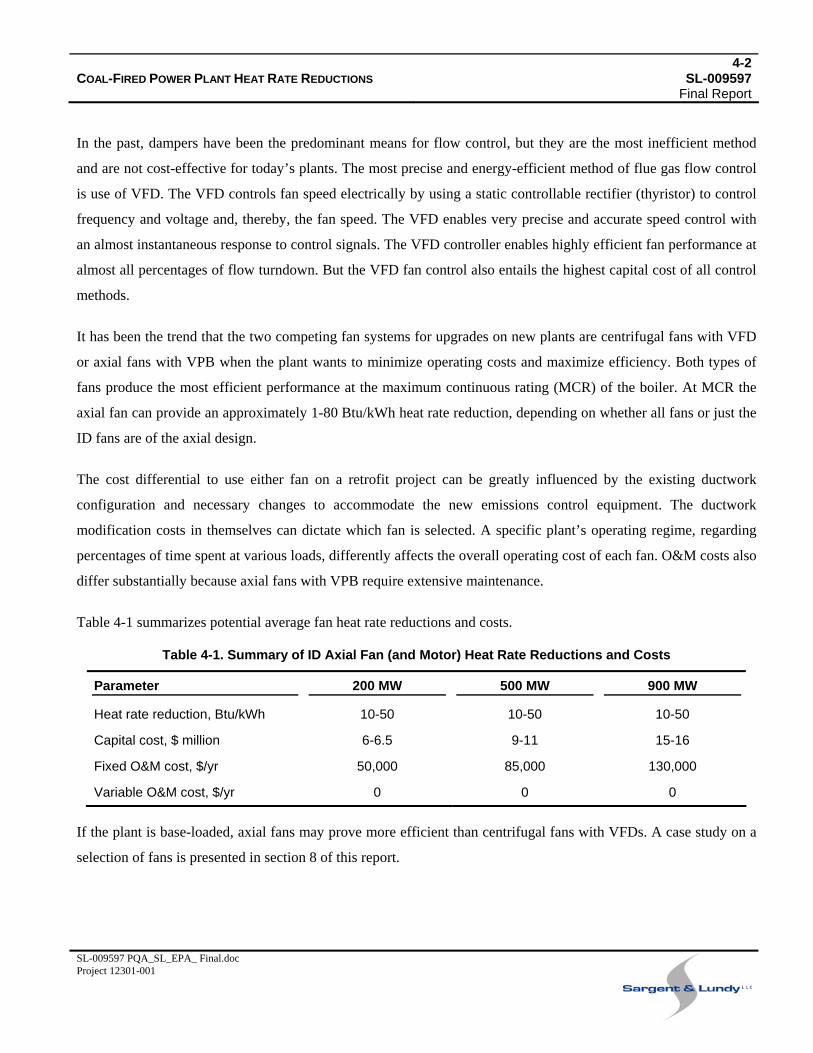
Table 4-1 summarizes potential average fan heat rate reductions and costs.
Table 4-1. Summary of ID Axial Fan (and Motor) Heat Rate Reductions and Costs
Parameter 200 MW 500 MW 900 MW
Heat rate reduction, Btu/kWh 10-50 10-50 10-50
Capital cost, $ million 6-6.5 9-11 15-16
Fixed O&M cost, $/yr 50,000 85,000 130,000
Variable O&M cost, $/yr 0 0 0
If the plant is base-loaded, axial fans may prove more efficient than centrifugal fans with VFDs. A case study on a
selection of fans is presented in section 8 of this report.
4-3COAL-FIRED POWER PLANT HEAT RATE REDUCTIONS SL-009597 Final Report
SL-009597 PQA_SL_EPA_ Final.doc Project 12301-001
4.2 VARIABLE-FREQUENCY DRIVES
Due to current electricity market conditions, many units no longer operate at base-load capacity and, therefore,
VFDs, also known as variable-speed drives (VSDs) on fans can greatly enhance plant performance at off-peak
loads. Additionally, because utilities are phasing in their environmental equipment upgrades, new fans are
oversized and operated at lower capacities until all additional equipment has been added. Under these scenarios,
VFDs can significantly improve the unit heat rate.
VFDs as motor controllers offer many substantial improvements to electric motor power requirements. The drives
provide benefits such as soft starts, which reduce initial electrical load, excessive torque, and subsequent equipment
wear during startups; provide precise speed control; and enable high-efficiency operation of motors at less than the
maximum efficiency point.Refs. , 28 51 During load turndown, plant auxiliary power can be reduced by 30-60% if all
large motors in a plant were to be efficiently controlled by VFD. With unit loads varying throughout the year, the
benefits of using VFDs on large-size equipment, such as FD or ID fans, boiler feedwater and condenser circulation
water pumps, can have significant impacts. Because plants today usually use either new booster ID fans or new ID
fans, the option of investing in VFDs generally appeals to plant operators since they are incurring long outages to
install the either new or additional air emission controls equipment. Depending on plant configuration, the
improvement in heat rate can range from 20-100 Btu/kWh. There are circumstances in which the heat rate
improvement has been estimated to be much higher, depending on the operation of the unit. Cycling units realize
the greatest gains representative of the upper range of heat rate improvement, whereas units which were designed
with excess fan capacity will exhibit the lower range. Heat rate improvements will vary when the VFD is compared
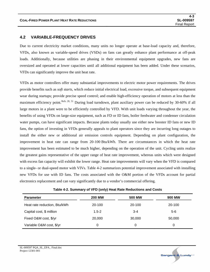
to a single- or dual-speed motor with VIVs. Table 4-2 summarizes potential improvement associated with installing
new VFDs for use with ID fans. The costs associated with the O&M portion of the VFDs account for partial
electronics replacement and can vary significantly due to a vendor’s commercial offering.
Table 4-2. Summary of VFD (only) Heat Rate Reductions and Costs
Parameter 200 MW 500 MW 900 MW
Heat rate reduction, Btu/kWh 20-100 20-100 20-100
Capital cost, $ million 1.5-2 3-4 5-6
Fixed O&M cost, $/yr 20,000 30,000 50,000
Variable O&M cost, $/yr 0 0 0
4-4COAL-FIRED POWER PLANT HEAT RATE REDUCTIONS SL-009597 Final Report
SL-009597 PQA_SL_EPA_ Final.doc Project 12301-001
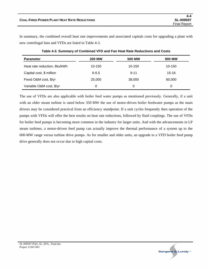
In summary, the combined overall heat rate improvements and associated capitals costs for upgrading a plant with
new centrifugal fans and VFDs are listed in Table 4-3.
Table 4-3. Summary of Combined VFD and Fan Heat Rate Reductions and Costs
Parameter 200 MW 500 MW 900 MW
Heat rate reduction, Btu/kWh 10-150 10-150 10-150
Capital cost, $ million 6-6.5 9-11 15-16
Fixed O&M cost, $/yr 25,000 38,000 60,000
Variable O&M cost, $/yr 0 0 0
The use of VFDs are also applicable with boiler feed water pumps as mentioned previously. Generally, if a unit
with an older steam turbine is rated below 350 MW the use of motor-driven boiler feedwater pumps as the main
drivers may be considered practical from an efficiency standpoint. If a unit cycles frequently then operation of the
pumps with VFDs will offer the best results on heat rate reductions, followed by fluid couplings. The use of VFDs
for boiler feed pumps is becoming more common in the industry for larger units. And with the advancements in LP
steam turbines, a motor-driven feed pump can actually improve the thermal performance of a system up to the
600-MW range versus turbine drive pumps. As for smaller and older units, an upgrade to a VFD boiler feed pump
drive generally does not occur due to high capital costs.
5-1COAL-FIRED POWER PLANT HEAT RATE REDUCTIONS SL-009597 Final Report
SL-009597 PQA_SL_EPA_ Final.doc Project 12301-001
5. EMISSIONS CONTROL TECHNOLOGIES
To meet environmental regulations, it has been regular practice for plant operators to implement emissions control
technologies. Among the typical technologies used in the industry are the three discussed in this section of the
report:
• FGD system
• Particulate control system, e.g., electrostatic precipitators (ESP)
• SCR system
These types of control technologies can consume relatively large amounts of auxiliary power. For example, a wet
FGD system typically requires 2-3% of the gross electrical output of a plant when the unit is combusting a high-
sulfur coal. In addition to general auxiliary power required to operate the apparatus, optimal performance may not
be realized due to natural wear on the system, inadequate maintenance, inefficient operation practices, and/or poor
operating conditions. Small adjustments or modifications can be made to these systems to alleviate a portion of the
electrical requirements necessary to accommodate these inefficiencies. Generally, FGD systems and ESPs are
technologies that can be modified to have the greatest impact on power consumption, while concurrently meeting
emissions collection requirements.Refs. , 20 25
The modifications to SCR systems generally entail optimizations to reduce flue gas pressure drops. Some
optimizations may be realized in the extensive ductwork usually involved with SCR retrofits and in other cases,
lower pressure drop catalysts are developed by vendors. In lesser amounts, auxiliary power may be reduced by
changes in the vaporization or mixing scheme of the SCR system.
5.1 FGD SYSTEM
Areas and means of potential improvement within an older FGD system are:
• Removal of venturi throat
• Improved flow distribution to lower the pressure drop across FGD
• Spray header operation
• Use of VFDs
5-2COAL-FIRED POWER PLANT HEAT RATE REDUCTIONS SL-009597 Final Report
SL-009597 PQA_SL_EPA_ Final.doc Project 12301-001
5.1.1 Removal of Venturi Throat
The designs of older coal-fired power plants commonly incorporated a venturi quencher prior to the absorber tower
to reduce the temperature of the flue gas prior to entering the desulfurization module. The venturi scrubber has a
converging section, in which the cross-sectional area is effectively decreased, causing an increase in fluid velocity.
This high-energy flue gas stream is introduced to quenching liquid, resulting in an effective barrier/mixing regime
that prevents hot gas from reaching the rubber-lined walls of the sump and absorber. Although a venturi is
particularly effective at quenching the flue gas stream, it is at the expense of additional flue gas pressure losses. The
resistance to flue gas flow incurred by the venturi quencher increases the power necessary to operate the ID fans.
To mitigate the flue gas flow resistances of a venturi quencher, a co-current spray tower quencher may be used
instead.
In a recently completed study for a 440-MW unit, the pressure drop across the venturi quencher alone was 6 inches
water column (in. w.c.). Because the unit was fan-limited during certain operating conditions, the pressure drop
across the quencher was considered a potential opportunity for efficiency improvement. A co-current, open-spray
quencher was designed to remedy the severe pressure losses. This resulted in the unit recovering 3 in. w.c., with an
associated delivery and installation cost of approximately $2.5 million. This reduction in pressure loss across the
quencher recovered 584 kW of power at the ID fan, which equated to a reduction in plant heat rate of
approximately 13 Btu/kWh.
5.1.2 Addition of Turning Vanes/Perforated Gas Distribution Plates
Improving gas flow distribution can have several advantages. One advantage is that an even flow distribution into
an absorber can increase the amount of flue gas coming in contact with the absorber sorbent and thus increase SO2
capture. Additionally, properly directed flue gas can eliminate persistent maintenance costs due to system
component erosion. Another advantage is that improved flow distribution can reduce the amount of energy
expended by the flue gas to navigate through turns in the ducting, which will reduce the power required by the ID
fan and thereby reduce operating costs.
A study based on computational fluid dynamics (CFD) modeling was performed to investigate possible upgrades on
a 450-MW wet FGD system with multiple absorbers. The study revealed that a possible upgrade entailed the
installation of turning vanes and perforated gas distribution plates at the inlet duct to the absorbers to improve the
flue gas flow into the third absorber. The vanes provided improved gas distribution into the third absorber, with
minimal pressure impact on the system. Addition of the vanes was estimated to cost approximately $250,000.
5-3COAL-FIRED POWER PLANT HEAT RATE REDUCTIONS SL-009597 Final Report
SL-009597 PQA_SL_EPA_ Final.doc Project 12301-001
For a unit with a flue gas velocity of about 60 feet per second (fps), a single 90-degree elbow in flue gas ducting
can result in an additional 0.5 in. w.c. pressure drop; the addition of turning vanes to the particular elbow can
reduce pressure drop losses by 0.2-0.3 in. w.c. For a typical 450-MW plant, this may equate to an approximately
1-2 Btu/kWh reduction in net heat rate.
Installation of turning/straightening vanes for directing flue gas flow is applicable for any existing elbows in the gas
duct. The technology is also relevant for other plant components, such as the inlet and outlet ducts of ESPs and
SCR systems.
5.1.3 Shutoff Spray Level
Multiple-spray levels are commonly installed in a wet FGD system for limestone slurry delivery, typically with a
dedicated slurry recirculation pump for each spray header. If a unit is operating below its permit SO2 emission
levels, it is possible to turn off one of the spray levels to save on auxiliary power necessary for pump operation. In
one particular study, a 450-MW unit with three FGD modules was evaluated to investigate the possibilities of
auxiliary power reduction by turning off one spray header pump on each absorber. The power savings resulted in
approximately 224 kW per FGD module. The effect was estimated to be a reduction in unit heat rate of
approximately 16 Btu/kWh for all three FGD modules operating. Turning off a slurry spray level would essentially
remove an absorption layer, thereby creating a more streamlined path for flue gas flow across the absorber tower.
This process is a relatively simple and effective means for reducing auxiliary power consumption of wet FGD
systems, with no additional operating costs.
For some older units, shutting off a slurry recirculation pump may actually prove deleterious to the system due to
elevated chances of plugging. For these situations, it may be possible to equip the recirculation pumps with VFDs
so the pumps can operate at a lower load. In this configuration, the pumps can continue to pump slurry to their
respective spray headers thereby reducing the chances of plugging problems while lowering overall system power
requirements.
5.1.4 Variable-Frequency Drives
In new FGD systems, VFDs typically are used on the slurry feed and blowdown pumps of large single-vessel
absorbers. This practice has become standard to accommodate changes in boiler load, particularly on units that
cycle regularly. When the amount of coal combusted is decreased, the sulfur content being oxidized decreases
accordingly, thus requiring less sorbent supply for SO2 capture. Likewise, the effects of turndown will decrease the
5-4COAL-FIRED POWER PLANT HEAT RATE REDUCTIONS SL-009597 Final Report
SL-009597 PQA_SL_EPA_ Final.doc Project 12301-001
rate of gypsum formation and therefore a VFD for the blowdown pump would be appropriate. VFDs are well suited
for such conditions because they allow power plants to reduce power consumption at low-load conditions and
improve the precision of material stream flow rates at off-design conditions.
Generally, wet FGD slurry recirculation pumps are not equipped with VFDs, as it is more economic to simply shut
off a pump at reduced load. However, as mentioned earlier, older units should consider furnishing recirculation
pumps with VFDs to prevent plugging of the slurry delivery system.
Table 5-1 summarizes the FGD system modification heat rate reductions and costs.
Table 5-1. Summary of FGD System Modification Heat Rate Reductions and Costs
Parameter 200 MW 500 MW 900 MW
Heat rate reduction, Btu/kWh 0-50 0-50 0-50
Capital cost, $ million 0-1 0-3 0-5
Fixed O&M cost, $/yr 0-50,000 0-100,000 0-150,000
Variable O&M cost, $/yr 0 0 0
5.2 PARTICULATE CONTROL SYSTEM
Approximately 90% of the coal-fired electric generating units in the U.S. that operate particulate control systems
use ESPs. The ESP operates by routing the particulate laden flue gas through a vessel which is divided into
multiple, vertical sections. Each section is energized with an applied voltage which creates an electric field between
a discharge electrode (DE) and a collection electrode (CE). The electric field ionizes the particles entrained in the
flue gas and enables their capture on the CE plates. Periodically, the plates are shaken and the particles are
dislodged and fall into hoppers for collection and removal.
To operate an ESP for optimal collection efficiency, the electric field strength in the inter-electrode region should
be at its maximum. To create a strong electric field, an ESP’s transformer/rectifier (T/R) set applies a direct current
to the DE to induce a voltage until a corona discharge is produced. The corona discharge creates free electrons,
which collide with the flue gas particulate matter effectively charging the particles. The charged particles are
attracted by the oppositely charged collecting plates where they accumulate. The difficulty arises when the voltage
is continuously increased, to maximize free ion formation, until spark-over occurs. Spark-over refers to internal
sparking that occurs between the discharge electrode and the grounded, collection electrode. An example to aid the
5-5COAL-FIRED POWER PLANT HEAT RATE REDUCTIONS SL-009597 Final Report
SL-009597 PQA_SL_EPA_ Final.doc Project 12301-001
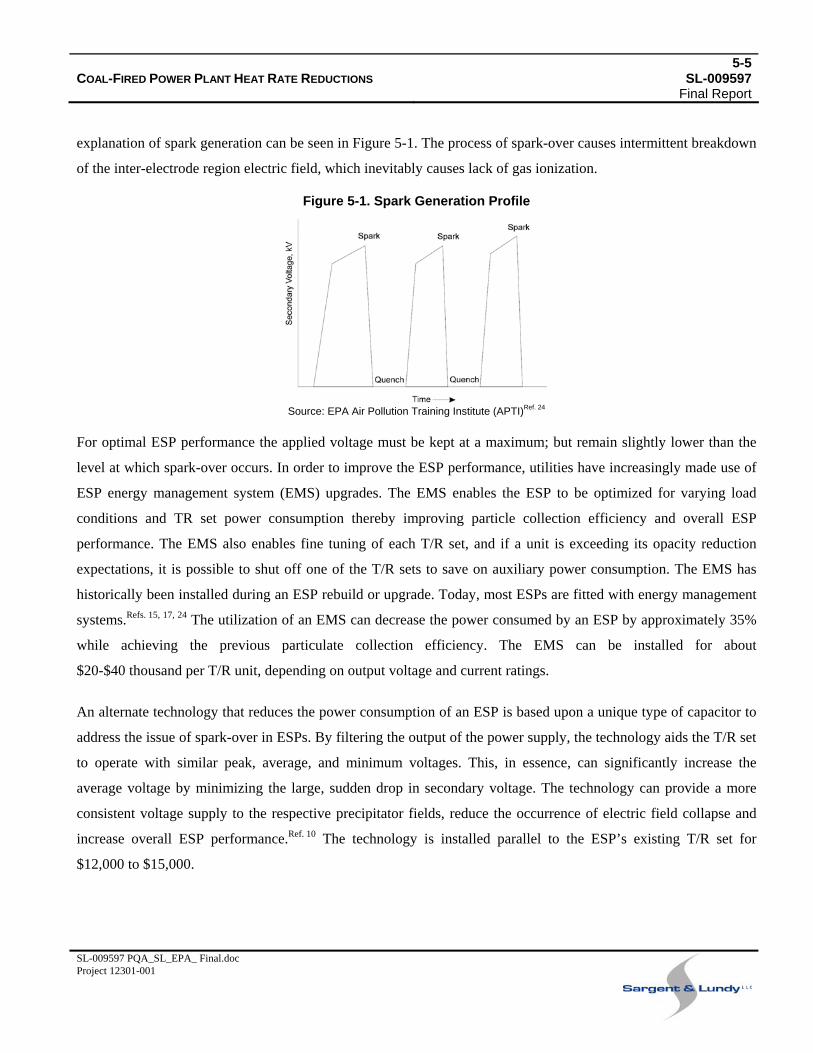
explanation of spark generation can be seen in Figure 5-1. The process of spark-over causes intermittent breakdown
of the inter-electrode region electric field, which inevitably causes lack of gas ionization.
Figure 5-1. Spark Generation Profile
Source: EPA Air Pollution Training Institute (APTI)Ref. 24
For optimal ESP performance the applied voltage must be kept at a maximum; but remain slightly lower than the
level at which spark-over occurs. In order to improve the ESP performance, utilities have increasingly made use of
ESP energy management system (EMS) upgrades. The EMS enables the ESP to be optimized for varying load
conditions and TR set power consumption thereby improving particle collection efficiency and overall ESP
performance. The EMS also enables fine tuning of each T/R set, and if a unit is exceeding its opacity reduction
expectations, it is possible to shut off one of the T/R sets to save on auxiliary power consumption. The EMS has
historically been installed during an ESP rebuild or upgrade. Today, most ESPs are fitted with energy management
systems.Refs. , , 15 17 24 The utilization of an EMS can decrease the power consumed by an ESP by approximately 35%
while achieving the previous particulate collection efficiency. The EMS can be installed for about
$20-$40 thousand per T/R unit, depending on output voltage and current ratings.
An alternate technology that reduces the power consumption of an ESP is based upon a unique type of capacitor to
address the issue of spark-over in ESPs. By filtering the output of the power supply, the technology aids the T/R set
to operate with similar peak, average, and minimum voltages. This, in essence, can significantly increase the
average voltage by minimizing the large, sudden drop in secondary voltage. The technology can provide a more
consistent voltage supply to the respective precipitator fields, reduce the occurrence of electric field collapse and
increase overall ESP performance.Ref. 10 The technology is installed parallel to the ESP’s existing T/R set for
$12,000 to $15,000.
5-6COAL-FIRED POWER PLANT HEAT RATE REDUCTIONS SL-009597 Final Report
SL-009597 PQA_SL_EPA_ Final.doc Project 12301-001
In general, upgrades and rebuilds of ESPs have enabled more efficient operation with a subsequent drop in power
requirements due to improved technology. But the benefits from such upgrades are not always apparent since a
utility may have to increase its particulate removal efficiency due to new environmental laws, in which case the
overall power consumption may increase.
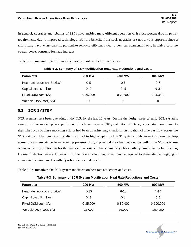
Table 5-2 summarizes the ESP modification heat rate reductions and costs.
Table 5-2. Summary of ESP Modification Heat Rate Reductions and Costs
Parameter 200 MW 500 MW 900 MW
Heat rate reduction, Btu/kWh 0-5 0-5 0-5
Capital cost, $ million 0-.2 0-.5 0-.8
Fixed O&M cost, $/yr 0-25,000 0-25,000 0-25,000
Variable O&M cost, $/yr 0 0 0
5.3 SCR SYSTEM
SCR systems have been operating in the U.S. for the last 10 years. During the design stage of early SCR systems,
extensive flow modeling was performed to achieve required NOX reduction efficiency with minimum ammonia
slip. The focus of these modeling efforts had been on achieving a uniform distribution of flue gas flow across the
SCR catalyst. The intensive modeling resulted in highly optimized SCR systems with respect to pressure drop
across the system. Aside from reducing pressure drop, a potential area for cost savings within the SCR is to use
secondary air as dilution air for the ammonia vaporizer. This technique yields auxiliary power saving by avoiding
the use of electric heaters. However, in some cases, hot-air bag filters may be required to eliminate the plugging of
ammonia injection nozzles with fly ash in the secondary air.
Table 5-3 summarizes the SCR system modification heat rate reductions and costs.
Table 5-3. Summary of SCR System Modification Heat Rate Reductions and Costs
Parameter 200 MW 500 MW 900 MW
Heat rate reduction, Btu/kWh 0-10 0-10 0-10
Capital cost, $ million 0-.5 0-1 0-2
Fixed O&M cost, $/yr 0-25,000 0-50,000 0-100,000
Variable O&M cost, $/yr 25,000 60,000 100,000

5-7COAL-FIRED POWER PLANT HEAT RATE REDUCTIONS SL-009597 Final Report
SL-009597 PQA_SL_EPA_ Final.doc Project 12301-001
In summary, adjustments to the emissions controls equipment may yield reductions in the power plant heat rate.
The estimated reductions and costs are listed in Table 5-4.
Table 5-4. Summary of Combined Environmental Controls Technology Heat Rate Reductions and Costs
Parameter 200 MW 500 MW 900 MW
Heat rate reduction, Btu/kWh 0-65 0-65 0-65
Capital cost, $ million 0-1.7 0-4.5 0-8
Fixed O&M cost, $/yr 0-100,000 0-175,000 0-275,000
Variable O&M cost, $/yr 25,000 60,000 100,000
6-1COAL-FIRED POWER PLANT HEAT RATE REDUCTIONS SL-009597 Final Report
SL-009597 PQA_SL_EPA_ Final.doc Project 12301-001
6. WATER TREATMENT SYSTEM
This section of the report discusses modifications to the water treatment system that offer potential reductions in
plant heat rate:
• Boiler water treatment
• Cooling tower improvements
6.1 BOILER WATER TREATMENT
Reduction of power plant heat rate as related to cooling systems and water treatment primarily involves maintaining
the proper water chemistry to reduce boiler scale and the amount of boiler water blowdown needed to control solids
and impurities.
Boiler scale lowers heat transfer due to low thermal conductivity. Heat transfer may be reduced as much as 5-10%
by the presence of scale. A scale approximately 1/8-inch-thick may cause an overall loss in boiler efficiency of
about 2-3% in fire tube boilers, as well as in the convective sections of water-tube boilers. More important than the
heat loss is that scale can cause overheating of the boiler tube metal and can result in subsequent tube failures,
leading to costly repairs and boiler outages.
Iron and copper content in condensate can corrode condensate systems. This reduces heat transfer efficiency and
could cause tube failure. Condensate corrosion control is required to protect process equipment, lines, tanks, as well
as to maintain the condensate as a quality feedwater source. Condensate system corrosion can result in increased
maintenance and equipment costs, energy loss through steam leaks, and loss of process heat transfer efficiency. To
prevent condensate corrosion, volatile neutralizing amines, such as cyclohexylamine, morpholine, and
diethylaminoethanol, typically are used to neutralize carbonic acid and raise the condensate pH. A blend of several
amines will ensure that corrosion protection is distributed throughout the entire steam/condensate system. The use
of filming amines present an alternative or additional condensate treatment process in which the compounds protect
the metal components by adhering to the surface and providing a protective layer.
High-purity water provides for greater boiler cycle concentration, thus reducing water and energy losses to
blowdown. Savings will be realized in reduced use of water treatment chemicals and water. High-quality water for
the thermal cycle can somewhat reduce the blowdown required. By reducing the blowdown amounts, more steam is
6-2COAL-FIRED POWER PLANT HEAT RATE REDUCTIONS SL-009597 Final Report
SL-009597 PQA_SL_EPA_ Final.doc Project 12301-001
available in the thermal cycle, thereby improving overall power plant efficiency and reducing heat rate. The
majority of utilities are aware of boiler chemistry and its associated issues. Most power plants already have the
most advanced water treatment systems installed, leaving minimal opportunity for further improvements regarding
new technology. The primary means of improvement relate to careful monitoring and maintenance of the water
treatment systems for optimal water quality.
6.2 COOLING WATER TREATMENT
Cooling tower water quality not only affects O&M costs of the cooling tower, but also enables cooling tower
operators to upgrade to advanced cooling tower packing. Advanced packing increases the overall thermal efficiency
of the tower by increasing mass transfer efficiency, as discussed in the next subsection. However, the high-
efficiency fills are more susceptible to fouling than are older style splash fill towers.
Water quality factors affecting cooling towers are those that lead to deposition on the cooling tower packing, such
as suspended solids. Those leading to cooling tower surface scaling include water hardness and biological fouling.
All three contaminants - deposition, scaling, and biological fouling - contribute to plugging of cooling tower fill.
Suspended solids in the cooling tower makeup water may be treated by a clarifier. The 10-15 ppm of suspended
solids that is commonly the guaranteed effluent quality from a clarifier is more than sufficient for cooling tower
makeup water.
The scaling tendency of water can be estimated based on the pH, alkalinity, calcium concentration, and temperature
of the water using scaling indices, such as the Langelier saturation index (LSI). The LSI indicates the number of pH
units the solution must be lowered in order to prevent scaling. The change in pH typically is affected by injection of
an acid, such as sulfuric acid. Care must be taken to prevent over-injection of acid as that may corrode the internals
of the cooling tower and circulating water heat exchange surfaces. Due to the recent increase in the cost of sulfuric
acid, specialty chemical suppliers offer alternatives to straight acid injection to prevent cooling tower scaling. These
chemical blends are tailored to the makeup water chemistry specific to the plant. Currently, there is no single
chemical blend that would be applicable to all plants for scaling control.
Sodium hypochlorite (bleach) is the industry-standard chemical for biological fouling control. Bleach is injected
either continuously at 1-2 ppm or injected at a shock dose of 5 ppm for 90 minutes 3 times per week. Bleach is
effective in preventing biological fouling due to microscopic organisms, such as the bacteria that lead to
Legionnaires’ disease, and macroscopic fouling, such as Asiatic clams and zebra mussels.
6-3COAL-FIRED POWER PLANT HEAT RATE REDUCTIONS SL-009597 Final Report
SL-009597 PQA_SL_EPA_ Final.doc Project 12301-001
It is important to note that when selecting more efficient fills, fouling degrades the effectiveness of the fill, so any
increase in efficiency gained by the use of high-efficiency film fill can be forfeited through the mismanagement of
cooling tower chemistry.
In general, by properly maintaining the quality of a power plant cooling water system, adequate efficiencies may be
obtained for the thermal cycle. Because the proper maintenance of water quality in the cooling system is not always
rigorously monitored, many plants have relied on condenser fouling as the primary means of measuring
performance decreases indirectly due to water quality. Additionally, advanced cooling tower packing cannot be
used unless the water quality meets a certain standard. This also renders water quality itself an indirect factor in
heat rate improvement, and one that is difficult to quantify.
6.3 ADVANCED COOLING TOWER PACKING
Wet cooling towers function by utilizing the cooling effect of evaporation and to a lesser extent, the transfer of heat
from the water to the ambient air through direct contact. The mass transfer from the liquid phase into the vapor
phase, and therefore the decrease in temperature, due to evaporation, is strongly dependent on the contact surface
area between the ambient air and the cooling water. In the past, cooling tower manufacturers increased the mass
transfer area by spraying the cooling water onto planks of redwood to break the water droplets into smaller droplets
and coat the surface of the planks with water. The planks were arranged such that ambient air was drawn across the
planks and then up trough the cooling tower fan. This is known as a cross-flow cooling tower since the air primarily
contacts the water in a horizontal cross flow arrangement. Cooling tower manufacturers have, within the last
20 years, altered the configuration of new cooling towers to a counter-flow design, where air and cooling water
flow counter-currently through the tower, air flowing up and water flowing down. The counter-flow configuration
provides an increase in the cooling tower thermal efficiency.
Both cross-flow and counter-flow cooling tower designs enable the implementation of more advanced film fill
packing material. The film fill packing configuration, which provides increased heat and mass transfer between the
air and water, can reduce the height (total amount) of packing required and thereby lower the fan power
requirements due to a lower total air flow friction and water pumping requirements (lower vertical height). For
older plant upgrades, the reduced pressure drop is probably the most significant form of heat rate reduction to be
achieved from such a project due to the lower power requirements of the fans; but increasing the total amount of
packing and thereby lowering the temperature of the water through the condenser can also have a significant impact
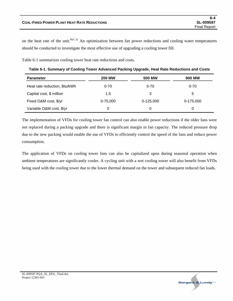
6-4COAL-FIRED POWER PLANT HEAT RATE REDUCTIONS SL-009597 Final Report
SL-009597 PQA_SL_EPA_ Final.doc Project 12301-001
on the heat rate of the unit.Ref. 22 An optimization between fan power reductions and cooling water temperatures
should be conducted to investigate the most effective use of upgrading a cooling tower fill.
Table 6-1 summarizes cooling tower heat rate reductions and costs.
Table 6-1. Summary of Cooling Tower Advanced Packing Upgrade, Heat Rate Reductions and Costs
Parameter 200 MW 500 MW 900 MW
Heat rate reduction, Btu/kWh 0-70 0-70 0-70
Capital cost, $ million 1.5 3 5
Fixed O&M cost, $/yr 0-75,000 0-125,000 0-175,000
Variable O&M cost, $/yr 0 0 0
The implementation of VFDs for cooling tower fan control can also enable power reductions if the older fans were
not replaced during a packing upgrade and there is significant margin in fan capacity. The reduced pressure drop
due to the new packing would enable the use of VFDs to efficiently control the speed of the fans and reduce power
consumption.
The application of VFDs on cooling tower fans can also be capitalized upon during seasonal operation when
ambient temperatures are significantly cooler. A cycling unit with a wet cooling tower will also benefit from VFDs
being used with the cooling tower due to the lower thermal demand on the tower and subsequent reduced fan loads.
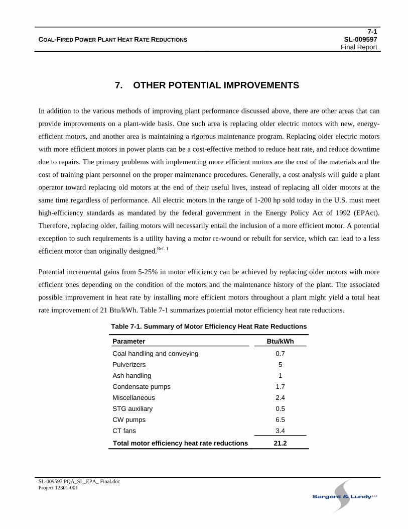
7-1COAL-FIRED POWER PLANT HEAT RATE REDUCTIONS SL-009597 Final Report
SL-009597 PQA_SL_EPA_ Final.doc Project 12301-001
7. OTHER POTENTIAL IMPROVEMENTS
In addition to the various methods of improving plant performance discussed above, there are other areas that can
provide improvements on a plant-wide basis. One such area is replacing older electric motors with new, energy-
efficient motors, and another area is maintaining a rigorous maintenance program. Replacing older electric motors
with more efficient motors in power plants can be a cost-effective method to reduce heat rate, and reduce downtime
due to repairs. The primary problems with implementing more efficient motors are the cost of the materials and the
cost of training plant personnel on the proper maintenance procedures. Generally, a cost analysis will guide a plant
operator toward replacing old motors at the end of their useful lives, instead of replacing all older motors at the
same time regardless of performance. All electric motors in the range of 1-200 hp sold today in the U.S. must meet
high-efficiency standards as mandated by the federal government in the Energy Policy Act of 1992 (EPAct).
Therefore, replacing older, failing motors will necessarily entail the inclusion of a more efficient motor. A potential
exception to such requirements is a utility having a motor re-wound or rebuilt for service, which can lead to a less
efficient motor than originally designed.Ref. 1
Potential incremental gains from 5-25% in motor efficiency can be achieved by replacing older motors with more
efficient ones depending on the condition of the motors and the maintenance history of the plant. The associated
possible improvement in heat rate by installing more efficient motors throughout a plant might yield a total heat
rate improvement of 21 Btu/kWh. Table 7-1 summarizes potential motor efficiency heat rate reductions.
Table 7-1. Summary of Motor Efficiency Heat Rate Reductions
Parameter Btu/kWh
Coal handling and conveying 0.7 Pulverizers 5 Ash handling 1 Condensate pumps 1.7 Miscellaneous 2.4 STG auxiliary 0.5 CW pumps 6.5 CT fans 3.4
Total motor efficiency heat rate reductions 21.2
7-2COAL-FIRED POWER PLANT HEAT RATE REDUCTIONS SL-009597 Final Report
SL-009597 PQA_SL_EPA_ Final.doc Project 12301-001
The total estimated plant-wide heat rate reduction that may be realized by motor replacements is not economically
feasible. It is known within the utility industry and commercial industries that replacing all old motors with more
efficient ones solely for heat rate improvement is not cost-effective. The most practical method is based on
replacing older motors that have failed or are expected to fail with new, more efficient motors. This is based on
industry discussions that indicate a large number of plants would not apply small-scale motor upgrades at
magnitudes large enough to significantly affect the heat rate.
The benefits of proper maintenance at a power plant facility can be substantial in terms of maintaining a plant’s
original heat rate. Modern data acquisitions systems and custom software programs on the market can enable plant
personnel to both monitor and simulate performance of various processes within a plant to analyze which
components are operating poorly. The savings through proper maintenance can result in several hundred Btu/kWh
of heat rate reductions. The primary cost incurred for such maintenance programs are for the man-hours to take
corrective action versus the initial capital expenditure to implement the data acquisition and analysis software.
Since it can be difficult to quantify the hours specifically allocated to certain fields of maintenance projects, the
benefits of proper maintenance can sometimes be underestimated.

8-1COAL-FIRED POWER PLANT HEAT RATE REDUCTIONS SL-009597 Final Report
SL-009597 PQA_SL_EPA_ Final.doc Project 12301-001
8. CASE STUDIES
This section discusses selected case studies prepared by S&L as part of the overall study effort:
• 250-MW PC plant
• 850-MW PC plant with FGD and baghouse
• Axial fans versus centrifugal fans
8.1 250-MW PC PLANT
A case study was performed for a 250-MW PC power plant built and commissioned in the 1970s, in which an
efficiency improvement analysis was conducted. Main steam conditions were 2360 psig/1000°F and reheat steam
was 1000°F. An ESP was used for emissions control. The analysis was conducted prior to implementation of new
environmental controls technology. The plant is currently operating at a heat rate of 9930 Btu/kWh; the original
design heat rate was 9110 Btu/kWh.
The boiler was designed to operate with 22% excess air and 3.5% oxygen (O2). Currently, the boiler operates very
near design efficiency, based on measuring inputs for dry gas loss, moisture loss, unburned carbon loss, radiation,
and other losses. The design efficiency is 88% and the current operating efficiency point is 87.4%. The most
significant improvement to the boiler would be to reduce the excess O2 concentration, which would yield a heat rate
savings of 25 Btu/kWh. Implementing such a change would involve an NN system with a combustion controls
module, at an estimated cost of $500,000.
The exhaust gas temperature leaving the air pre-heater is approximately 59-70°F higher than the original design
value. The plant uses a LjungstrÖm, regenerative air pre-heater. A reduction in flue gas temperatures could be
obtained by installing additional air pre-heater surface area via the baskets. But additional analysis is required due
to acid dew point temperatures and the resultant effects. By reducing the flue gas temperature to the design value, a
subsequent reduction in heat rate of 92 Btu/kWh can be realized at a cost of $2,000,000 for a new air heater with
additional surface area.
The air pre-heater leakage was measured to be approximately 8%. Although measured air pre-heater leakage values
are often much lower than actual, in this case it is assumed to be 8% due to the well-maintained plant. The potential
improvement in heat rate is expected to be 4 Btu/kWh by installing new seals at a cost of $300,000.
8-2COAL-FIRED POWER PLANT HEAT RATE REDUCTIONS SL-009597 Final Report
SL-009597 PQA_SL_EPA_ Final.doc Project 12301-001
The steam turbine was evaluated for possible upgrades. Much advancement has been made in steam turbine
technology since the 1970s and is certainly applicable as an upgrade. In most cases there is substantially more to be
gained from larger units from an economic standpoint. In this case, a new rotor and stationary blades are suggested.
The expected improvement will yield an additional 2-3 MW for the HP cylinder, 2-3 MW for the IP cylinder, and
1-2 MW for the LP cylinder. The reduction in heat rate is expected to be 255 Btu/kWh at a cost of $10,200,000 for
this 250-MW unit. From an economic standpoint the industry tends to implement such steam turbine upgrades with
emphasis first on the HP and then LP and IP sections, respectively.
The steam turbine was also evaluated to reduce steam leakage between the shaft and casing. The reduction in heat
rate is estimated to be 15 Btu/kWh at a cost of $300,000.
The steam condenser is a once-through design and has been cleaned offline once a year. The steam condenser’s
materials had degraded considerably over time and a new steam condenser was recently installed to replace it. The
condenser was replaced due to excessive tube plugging and condenser leaks and the high costs associated with the
necessary repairs. The new condenser has stainless steel tubing and an online cleaning system. No improvements to
this new system were considered.
The various electrical drive motors on the plant were taken into consideration. Most of the motors within the plant
are already operating at an efficiency of approximately 93%. An expected increase to 95% by replacing all existing
motors is not economically justified.
VFDs could be used on a number of large-scale motors at the plant. The use of VFDs at the plant will probably be
analyzed prior to beginning back end plant upgrades.
The main boiler feed pump is steam-driven. An overhaul and upgrade to the pump could reduce the plant’s heat rate
by 37 Btu/kWh, at a cost of $300,000.
Feedwater heaters were considered for potential improvements. The percentage of plugged tubing was not
excessive, and any possible upgrades were not considered economic given the small expected heat rate reduction
and associated costs.
The plant was examined for steam leaks. A survey for visual steam leaks and a review of plant data provided no
indication that a large loss was occurring.
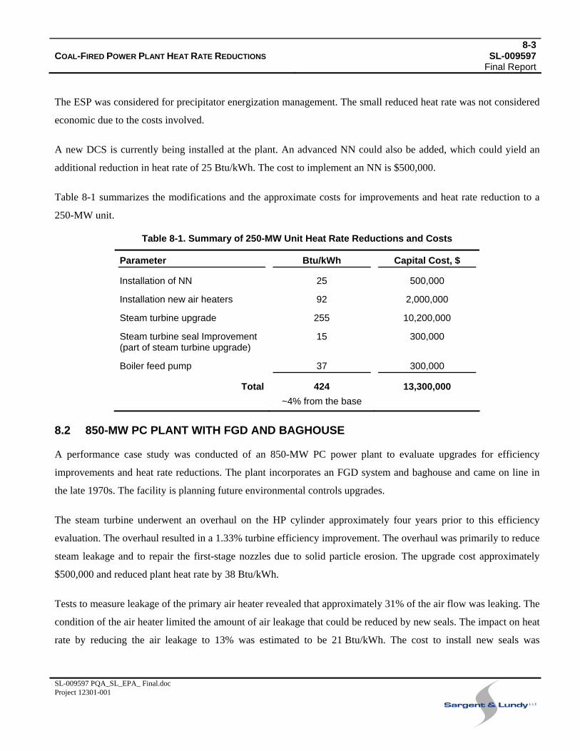
8-3COAL-FIRED POWER PLANT HEAT RATE REDUCTIONS SL-009597 Final Report
SL-009597 PQA_SL_EPA_ Final.doc Project 12301-001
The ESP was considered for precipitator energization management. The small reduced heat rate was not considered
economic due to the costs involved.
A new DCS is currently being installed at the plant. An advanced NN could also be added, which could yield an
additional reduction in heat rate of 25 Btu/kWh. The cost to implement an NN is $500,000.
Table 8-1 summarizes the modifications and the approximate costs for improvements and heat rate reduction to a
250-MW unit.
Table 8-1. Summary of 250-MW Unit Heat Rate Reductions and Costs
Parameter Btu/kWh Capital Cost, $
Installation of NN 25 500,000
Installation new air heaters 92 2,000,000
Steam turbine upgrade 255 10,200,000
Steam turbine seal Improvement (part of steam turbine upgrade)
15 300,000
Boiler feed pump 37 300,000
Total 424 13,300,000 ~4% from the base
8.2 850-MW PC PLANT WITH FGD AND BAGHOUSE
A performance case study was conducted of an 850-MW PC power plant to evaluate upgrades for efficiency
improvements and heat rate reductions. The plant incorporates an FGD system and baghouse and came on line in
the late 1970s. The facility is planning future environmental controls upgrades.
The steam turbine underwent an overhaul on the HP cylinder approximately four years prior to this efficiency
evaluation. The overhaul resulted in a 1.33% turbine efficiency improvement. The overhaul was primarily to reduce
steam leakage and to repair the first-stage nozzles due to solid particle erosion. The upgrade cost approximately
$500,000 and reduced plant heat rate by 38 Btu/kWh.
Tests to measure leakage of the primary air heater revealed that approximately 31% of the air flow was leaking. The
condition of the air heater limited the amount of air leakage that could be reduced by new seals. The impact on heat
rate by reducing the air leakage to 13% was estimated to be 21 Btu/kWh. The cost to install new seals was
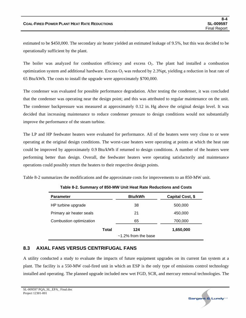
8-4COAL-FIRED POWER PLANT HEAT RATE REDUCTIONS SL-009597 Final Report
SL-009597 PQA_SL_EPA_ Final.doc Project 12301-001
estimated to be $450,000. The secondary air heater yielded an estimated leakage of 9.5%, but this was decided to be
operationally sufficient by the plant.
The boiler was analyzed for combustion efficiency and excess O2. The plant had installed a combustion
optimization system and additional hardware. Excess O2 was reduced by 2.3%pt, yielding a reduction in heat rate of
65 Btu/kWh. The costs to install the upgrade were approximately $700,000.
The condenser was evaluated for possible performance degradation. After testing the condenser, it was concluded
that the condenser was operating near the design point; and this was attributed to regular maintenance on the unit.
The condenser backpressure was measured at approximately 0.12 in. Hg above the original design level. It was
decided that increasing maintenance to reduce condenser pressure to design conditions would not substantially
improve the performance of the steam turbine.
The LP and HP feedwater heaters were evaluated for performance. All of the heaters were very close to or were
operating at the original design conditions. The worst-case heaters were operating at points at which the heat rate
could be improved by approximately 0.9 Btu/kWh if returned to design conditions. A number of the heaters were
performing better than design. Overall, the feedwater heaters were operating satisfactorily and maintenance
operations could possibly return the heaters to their respective design points.
Table 8-2 summarizes the modifications and the approximate costs for improvements to an 850-MW unit.
Table 8-2. Summary of 850-MW Unit Heat Rate Reductions and Costs
Parameter Btu/kWh Capital Cost, $
HP turbine upgrade 38 500,000
Primary air heater seals 21 450,000
Combustion optimization 65 700,000
Total 124 1,650,000 ~1.2% from the base
8.3 AXIAL FANS VERSUS CENTRIFUGAL FANS
A utility conducted a study to evaluate the impacts of future equipment upgrades on its current fan system at a
plant. The facility is a 550-MW coal-fired unit in which an ESP is the only type of emissions control technology
installed and operating. The planned upgrade included new wet FGD, SCR, and mercury removal technologies. The
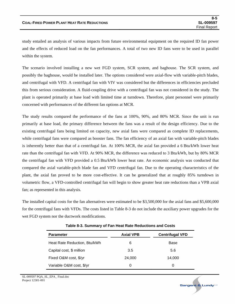
8-5COAL-FIRED POWER PLANT HEAT RATE REDUCTIONS SL-009597 Final Report
SL-009597 PQA_SL_EPA_ Final.doc Project 12301-001
study entailed an analysis of various impacts from future environmental equipment on the required ID fan power
and the effects of reduced load on the fan performances. A total of two new ID fans were to be used in parallel
within the system.
The scenario involved installing a new wet FGD system, SCR system, and baghouse. The SCR system, and
possibly the baghouse, would be installed later. The options considered were axial-flow with variable-pitch blades,
and centrifugal with VFD. A centrifugal fan with VIV was considered but the differences in efficiencies precluded
this from serious consideration. A fluid-coupling drive with a centrifugal fan was not considered in the study. The
plant is operated primarily at base load with limited time at turndown. Therefore, plant personnel were primarily
concerned with performances of the different fan options at MCR.
The study results compared the performance of the fans at 100%, 90%, and 80% MCR. Since the unit is run
primarily at base load, the primary difference between the fans was a result of the design efficiency. Due to the
existing centrifugal fans being limited on capacity, new axial fans were compared as complete ID replacements,
while centrifugal fans were compared as booster fans. The fan efficiency of an axial fan with variable-pitch blades
is inherently better than that of a centrifugal fan. At 100% MCR, the axial fan provided a 6 Btu/kWh lower heat
rate than the centrifugal fan with VFD. At 90% MCR, the difference was reduced to 3 Btu/kWh, but by 80% MCR
the centrifugal fan with VFD provided a 0.5 Btu/kWh lower heat rate. An economic analysis was conducted that
compared the axial variable-pitch blade fan and VFD centrifugal fan. Due to the operating characteristics of the
plant, the axial fan proved to be more cost-effective. It can be generalized that at roughly 85% turndown in
volumetric flow, a VFD-controlled centrifugal fan will begin to show greater heat rate reductions than a VPB axial
fan; as represented in this analysis.
The installed capital costs for the fan alternatives were estimated to be $3,500,000 for the axial fans and $5,600,000
for the centrifugal fans with VFDs. The costs listed in Table 8-3 do not include the auxiliary power upgrades for the
wet FGD system nor the ductwork modifications.
Table 8-3. Summary of Fan Heat Rate Reductions and Costs
Parameter Axial VPB Centrifugal VFD
Heat Rate Reduction, Btu/kWh 6 Base
Capital cost, $ million 3.5 5.6
Fixed O&M cost, $/yr 24,000 14,000
Variable O&M cost, $/yr 0 0
9-1COAL-FIRED POWER PLANT HEAT RATE REDUCTIONS SL-009597 Final Report
SL-009597 PQA_SL_EPA_ Final.doc Project 12301-001
9. REFERENCES
9.1 TECHNOLOGY VENDORS
Discussions were held with the following vendors during this study. Additionally, many useful case studies were
obtained from the vendors listed below.
1. ABB
2. Alstom
3. Babcock & Wilcox
4. Babcock Power International
5. Conco
6. General Electric
7. GE Energy/BHA Group GmbH
8. Howden
9. NeuCo
10. NWL Transformers, Inc.
11. Paragon
12. Riley Power Inc.
13. RMB Engineering
14. Siemens
9.2 SURVEYED LITERATURE
The various literature and sources listed below were surveyed as part of this study.
15. Aa, P., Reviving an Electrostatic Precipitator: "Rebuilding can increase cost effectiveness and design flexibility," November 2001, www.hamonusa.com
16. Barnoski. S.; et al., “Coal Mill and Combustion Optimization on a Once-through, Supercritical Boiler with Multivariable Predictive Control,” Proceedings from 48th Annual ISA POWID Symposium, Nashville, TN, June 2005.
17. Blankinship, S., ESP Enhancements Can Up Performance at Nominal Cost. Power Engineering, January 2003 -- http://pepei.pennnet.com/display_article/166309/6/ARTCL/none/none/1/ESP-Enhancements-Can-Up-Performance-at-Nominal-Cost/
9-2COAL-FIRED POWER PLANT HEAT RATE REDUCTIONS SL-009597 Final Report
SL-009597 PQA_SL_EPA_ Final.doc Project 12301-001
18. Boncimino, G.; W. Stenzel, I. Torrens, Costs and Effectiveness of Upgrading and Refurbishing Older Coal-Fired Power Plants in Developing APEC Economies, Power House Engineering Ltd, Texas, 2005, http://www.egcfe.ewg.apec.org/studies.htm
19. Brandt, C.; A. Tremmel; H. Klotz, “ALSTOM Steam Turbine Design of World’s Largest Single Shaft Units in Most Advanced Ultra-supercritical Steam Power Plants,” Proceedings from Power-Gen Europe, 26-28 June, 2007.
20. Carstens, A., R. Gaikwad, W. Siegfriedt, Performance Upgrades for Low-Sulfur Wet Scrubbers, Coal-Gen 2008.
21. Cheski, J. R., R. Patel, K. Rockaway, H. Osaghae, M. Christianson, “A Large Steam Turbine Retrofit Design and Operation History,” Power-Gen International Conference, Las Vegas, NV, 2005.
22. Dend, T, “Evaluating Cooling Tower Upgrades,” CEP, May, 2008.
23. Dreier Jr., D. R., “Upgradable Opportunities for Steam Turbines,” GE Power Generation, GER-3696D.
24. EPA Air Pollution Training Institute (APTI), 25 June 2008, http://www.epa.gov/air/oaqps/eog/course_listing.html -- updated October 2007
25. Farber, P., S. Katzberger, W. Siegfriedt, Results of FGD Upgrade Projects on Low-Rank Coals, Electric Power 2007 Conference and Exhibition.
26. Flynn, T. J., “Applying Nonlinear Signal Analysis Techniques to Flame Scanner Signals to Improve Staging of Cyclone Boilers for NOx Control,” Symposium CD, Power Plant Air Pollutant Control “MEGA” Symposium, Baltimore, MD, August 2006.
27. Flynn, T., D. Stuart, et al., “Flame Monitoring Enhances Burner Management,” Power Engineering, February, 2003.
28. Gray, J., “New Env. Eqpt., Plant Cycling Patterns, Noise Regulations and Metallurgy Developments are Causing Operators to Consider Updating the Backbone of their Air Handling Systems,” Power Engineering, April 2008.
29. Guffre, J., “Air Heater Maintenance,” Power, Feb. 2007.
30. Guffre, J., “Air Heater Leakage: Worse Than You Think,” Power, April, 2006.
31. Hurd, P., F. Truckenmueller, N. Thamm, H. Pollak, M. Neef, M. Deckers, “Modern Reaction HP/IP Turbine Technology Advances & Experiences,” Proceedings from PWR2005 ASME Power, Chicago, IL, 5-7 April, 2005.
32. Intelligent Sootblowing at Texas Genco’s W. A. Parish Plant, EPRI, Palo Alto, CA, and Texas Genco Holding Company, Inc., Houston TX, 2004. 1011330.
33. Kitto, Jr., J. B., S. A. Bryk, J. M. Piepho, “Upgrades and Enhancements for Competitive Coal-Fired Boiler Systems,” Babcock & Wilcox, Technical Paper.
34. Labbe, D. et al., “Dynamic NOX/Heat Rate Optimization,” Proceedings from 16th Annual Joint POWID/EPRI Controls & Inst. Conf. 49th Ann. ISA POWID Symp. San Jose, CA, June 2006.
35. Lesiuk, J. F, “Steam Turbine Uprates,” GE Power Systems, GER 4199.
9-3COAL-FIRED POWER PLANT HEAT RATE REDUCTIONS SL-009597 Final Report
SL-009597 PQA_SL_EPA_ Final.doc Project 12301-001
36. Mac Duff, E. J., N. D. Clark, “Ljungstrom Air Preheater Design and Operation,” Combustion, Jan. & March 1976.
37. Nakoneczny, G. J., K. L. Noel, “Implementing B&W’s Intelligent Sootblowing System at MidAmerican Energy Company’s Louisa Energy Center Unit 1,” Proceedings from Western Fuels Conference, New Mexico, August 12-13, 2002.
38. National Coal Council, Increasing Electricity Availability from Coal-Fired Generation in the Near-Term, May 2001 -- http://www.nationalcoalcouncil.org
39. National Energy Technology Laboratory, “Lignite Fuel Enhancement Project,” Power Engineering -- http://pepei.pennnet.com/
40. Paragon Airheater Technologies, “Reducing Preheater Leakage Boosts Output and Availability,” Power Engineering, August 2005.
41. Power Engineering International, Editors, “Reducing Preheater Leakage Boosts Output and Availability,” Power Engineering, August 2005.
42. R. E. Putman, Steam Surface Condensers: Basic Principles, Performance Monitoring, and Maintenance, ASME Press, New York, 2001.
43. Rodgers, D., D. Mason, “Improving Heat Rate by Input/Loss Monitoring,” Power Magazine, October 2003.
44. Romer, C. et al., “Boiler Optimization for Multi-Pollutant Control: Mercury and NOX Emissions,” Symposium CD, Proceedings from Power Plant Air Pollutant Control “MEGA” Symposium, Baltimore, MD, August 2006.
45. Sarunac, N., M. Cilinski, et al., “Sootblowing Optimization for Opacity Control,” Proceedings from Power Plant Air Pollutant Control “MEGA” Symposium, Baltimore, MD, August 2006.
46. Saxon, G., R. E. Putman, “The Practical Application and Innovation of Cleaning Technology for Heat Exchangers,” Proceedings from 2003 ECI Conference on Heat Exchanger Fouling and Cleaning: Fundamentals and Applications, Santa Fe, NM, 2003.
47. Schaarschmidt, A., E. Jenikejew, G. Nitch, B. Michels, “Performance Increase Through World Class Technology and Implementation,” Siemens AG, Power Generation Technical Paper, 2005.
48. Smiarowski, M. W., R. Leo, C. Scholten, J. Blake, “Steam Turbine Modernization Solutions Provide A Wide Spectrum of Options to Improve Performance,” Siemens Power Generation Technical Paper, 2005.
49. Steam, its Generation and Use, 41st Edition; J. B. Kitto, S. C. Stultz Eds., The Babcock & Wilcox Co., Barberton, OH, USA, 2005.
50. Stephen, D., R. Hesterman, P. Bartley, “Establishing Optimal Thermal Conditions for Steam Power Plant Retrofits,” Proceedings from San Francisco Steam Turbine Retrofit Conference, San Francisco, CA, 16-17 September 2003.
51. U.S. Department of Energy, Issue Focus: Adjustable Speed Drive Technologies, ITP Energy Matters: March/April 2000 -- http://www. eere.energy.gov/industry/bestpractices/energymatters/full_issue.cfm/volume=10

9-4COAL-FIRED POWER PLANT HEAT RATE REDUCTIONS SL-009597 Final Report
SL-009597 PQA_SL_EPA_ Final.doc Project 12301-001
52. U.S. Department of Energy, NETL, Big Bend Power Station Neural Network-Sootblower Optimization, June 2006, Doc. No. DOE/NETL-2006/1234 -- http://www.netl.doe.gov
53. U.S. Department of Energy, NETL, Demonstration of Integrated Optimization Software at the Baldwin Energy Complex, Final Technical Report, Issued February 2008, Coop. Agreement DE-FC26-04NT41768 -- http://www.netl.doe.gov/technologies/coalpower/cctc/ccpi/pubs/41768R016.pdf
54. Warriner, J. N., R. Booth, D. Linkins, G. Nunley, R. Frank, D. Sands, “Intelligent Sootblowing for Full Unit Optimization.”