CO2 Quality and Other Relevant Issues
41
CO Quality and Other CO 2 Quality and Other Relevant Issues Oxyfuel Process (Post-Combustion Capture) (Pre-Combustion Capture) Institute of Energy Systems Introduction and Objectives of the Meeting A. Kather Energy Systems Hamburg University of Technology 2 nd Working Group Meeting on CO 2 Quality and Other Relevant Issues 7 th September 2009, Cottbus
Transcript of CO2 Quality and Other Relevant Issues

CO Quality and Other CO2 Quality and Other Relevant Issues
Oxyfuel Process(Post-Combustion Capture)(Pre-Combustion Capture)
Institute ofEnergy Systems
Introduction and Objectives of the MeetingA. Kather
Energy Systems
Hamburg University of Technology
2nd Working Group Meeting on CO2 Quality and Other Relevant Issues
7th September 2009, Cottbus
CO2 purity
Introduction• Introduction
▸What are the barriers for a successful deployment of the OxyfuelProcess?
▸Why considering the impurities?
• General Boundary Conditions of the Oxyfuel Process
▸Flue gas recycle demand; O2 excess; O2 concentration
• Impact of Impurities on the CO2 Concentration
▸Where do the impurities come from?
• R&D Project COORAL
▸Definition of required CO2 purity
• Possibilities to increase CO2 Purity
2

CO2 purity
Introduction• Introduction
▸What are the barriers for a successful deployment of the OxyfuelProcess?
▸Why considering the impurities?
• General Boundary Conditions of the Oxyfuel Process
▸Flue gas recycle demand; O2 excess; O2 concentration
• Impact of Impurities on the CO2 Concentration
▸Where do the impurities come from?
• R&D Project COORAL
▸Definition of required CO2 purity
• Possibilities to increase CO2 Purity
3
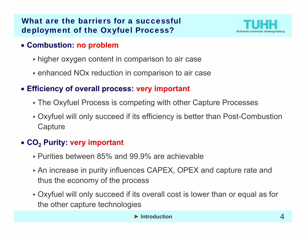
What are the barriers for a successful deployment of the Oxyfuel Process?
Combustion: no problem• Combustion: no problem
▸higher oxygen content in comparison to air case
▸enhanced NOx reduction in comparison to air case▸enhanced NOx reduction in comparison to air case
• Efficiency of overall process: very important
▸The Oxyfuel Process is competing with other Capture Processes▸The Oxyfuel Process is competing with other Capture Processes
▸Oxyfuel will only succeed if its efficiency is better than Post-Combustion Capture
• CO2 Purity: very important
▸Purities between 85% and 99.9% are achievable
▸An increase in purity influences CAPEX, OPEX and capture rate and thus the economy of the process
O f l ill l d if it ll t i l th l f▸Oxyfuel will only succeed if its overall cost is lower than or equal as for the other capture technologies
4► Introduction
CO2 purity
Introduction• Introduction
▸What are the barriers for a successful deployment of the OxyfuelProcess?
▸Why considering the impurities?
• General Boundary Conditions of the Oxyfuel Process
▸Flue gas recycle demand; O2 excess; O2 concentration
• Impact of Impurities on the CO2 Concentration
▸Where do the impurities come from?
• R&D Project COORAL
▸Definition of required CO2 purity
• Possibilities to increase CO2 Purity
5

Why considering the impurities?
Directive 2009/31/EC ( 23 April 2009) Article 12Directive 2009/31/EC ( 23 April 2009) Article 12
CO2 stream acceptance criteria and procedure
1. A CO2 stream shall consist overwhelmingly of carbon dioxide. To this end, no waste or other matter may be added for the purpose of disposing of that waste or other matter. However, a CO2 stream may contain incidental associated substances from the source, capture or injection process and trace substances added to assist in monitoring and verifying CO2 migration. Concentrations of all incidental and added substances shall be below levels that would:
(a) adversely affect the integrity of the storage site or the relevant transport infrastructure;transport infrastructure;
(b) pose a significant risk to the environment or human health; or
( ) b h th i t f li bl C it l i l ti(c) breach the requirements of applicable Community legislation.
6► Introduction

Why considering the impurities?
CO Purity: very important• CO2 Purity: very important
▸Purities between 85% and 99.9% are achievable
▸An increase in purity influences CAPEX OPEX and capture rate and▸An increase in purity influences CAPEX, OPEX and capture rate and thus the economy of the process
▸Oxyfuel will only succeed if its overall cost is lower than other capture technologies
7► Introduction

Why considering the impurities?
CAPEX OPEX and capture rate 15:30 17:15• CAPEX, OPEX and capture rate 15:30 – 17:15
• Requirements for the storage site 13:15 – 15:15
Geologists must define the concentration limits▸Geologists must define the concentration limits
▸Will there be different limits for different storage options?
Requirements for the transport (mainly pipeline) 11:55 12:20• Requirements for the transport (mainly pipeline) 11:55 – 12:20
▸Will there be different limits for the different transport options?
Requirements for the recycled flue gas• Requirements for the recycled flue gas
▸ Internal question of boiler design considerations, mainly related to corrosion
• Requirements for health, safety and environmental (HSE) reasons
▸Not subject of today’s discussion
8► Introduction

CO2 purity
Introduction• Introduction
▸What are the barriers for a successful deployment of the OxyfuelProcess?
▸Why considering the impurities?
• General Boundary Conditions of the Oxyfuel Process
▸Flue gas recycle demand; O2 excess; O2 concentration
• Impact of Impurities on the CO2 Concentration
▸Where do the impurities come from?
• R&D Project COORAL
▸Definition of required CO2 purity
• Possibilities to increase CO2 Purity
9

Oxyfuel Process – simplified process scheme
Air SeparationUnit
N
Flue Gas Recycle
2/3Flue Gas
Air
15 % CO26 % H2O
76 % N2
66 % CO226 % H2O8 % Ar, N2,
N2
O289 % CO211 % N2, Ar,
O
1/3
Drying
23 % Ar, O2, …
, 2,O2, …
H2O
O2, …
Coalexhaust gas
18 %47 % CO253 % Ar, N2,
O2, …
exhaust gas
CO2 Separation
82 %nearly pureCO2
all percentages as
98 % CO22 % N2, Ar, O2,
NOx, SO2
10
Unitall percentages asmolar percentage
► General Boundary Conditions of the Oxyfuel Process

Factors influencing the recycle requirement (I)
Main boundary conditions for the boiler:
• Steam temperature in the boiler wall is limited to 470 °C due to material reasons
• Flue gas temperature at the exit of the combustion chamber should not exceed the temperature in the air case (slagging)
• Both conditions can approximately be fulfilled (for tRecycle < 400°C) if the condition
t = t
1250 °C1250 °C
tadiabatic, Air = tadiabatic, O2+Recycle
is used.tRecycle
tO2
tadiabatic
11
Q&tCoal
tadiabatic
► General Boundary Conditions of the Oxyfuel Process

Factors influencing the recycle requirement (II)
tRecycle
tO
Q&
tO2
tCoal
tadiabatic
• Condition:tadiabatic, Air = tadiabatic, O2+Recycle de
man
d, , 2 y
• Underlying assumptions:tAir = 320 °C
25 °C
recy
cle
tO2= 25 °C
tCoal = 40 °CO2 excess: 15 %
12
2
O2 purity: 98 %
► General Boundary Conditions of the Oxyfuel Process

CO2 purity
Introduction• Introduction
▸What are the barriers for a successful deployment of the OxyfuelProcess?
▸Why considering the impurities?
• General Boundary Conditions of the Oxyfuel Process
▸Flue gas recycle demand; O2 excess; O2 concentration
• Impact of Impurities on the CO2 Concentration
▸Where do the impurities come from?
• R&D Project COORAL
▸Definition of required CO2 purity
• Possibilities to increase CO2 Purity
13

Where do the impurities come from?
▸ Fuel’s nitrogen and sulfur SOx, NOx
Durch konstruktive Maßnahmen zu erzielender Falschluftanteil
► Impact of impurities on the CO2 concentration 14
)
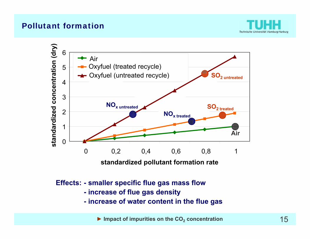
Pollutant formation
5
6at
ion
(dry
)AirOxyfuel (treated recycle) Oxyfuel (untreated recycle) SO
3
4
conc
entr
a Oxyfuel (untreated recycle)
SONO
SO2 untreated
1
2
ndar
dize
d
Air
NOx treated
SO2 treatedNOx untreated
00 0,2 0,4 0,6 0,8 1
standardized pollutant formation rate
stan
Air
p
Effects: - smaller specific flue gas mass flow - increase of flue gas density
15
g y- increase of water content in the flue gas
► Impact of impurities on the CO2 concentration

Where do the impurities come from?
▸ Fuel’s nitrogen and sulfur SOx, NOx
N l ll l d NO i d d▸ Nearly all recycled NOx is reduced
▸ No sense to install DeNOx plant before the flue gas recirculation
▸Only a small part of SO2 is reduced
1616► Impact of impurities on the CO2 concentration
SO
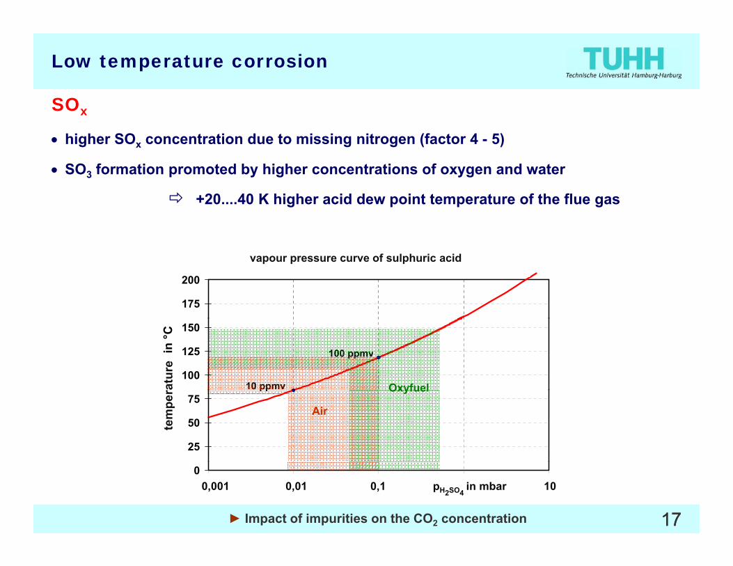
Low temperature corrosion
SOx
• higher SOx concentration due to missing nitrogen (factor 4 - 5)
• SO3 formation promoted by higher concentrations of oxygen and water 3 p y g yg
+20....40 K higher acid dew point temperature of the flue gas
Dampfdruckkurve von Schwefelsäure
175
200
vapour pressure curve of sulphuric acid
100
125
150
erat
ur in
°C
10 ppmv
100 ppmv
Oxyfuelratu
re
25
50
75
Tem
p
pp
Air
Oxyfuel
tem
per
1717
01,0E-06 1,0E-05 1,0E-04 1,0E-03 1,0E-02Druck in bar0,001 0,01 0,1 pH2SO4
in mbar 10
► Impact of impurities on the CO2 concentration
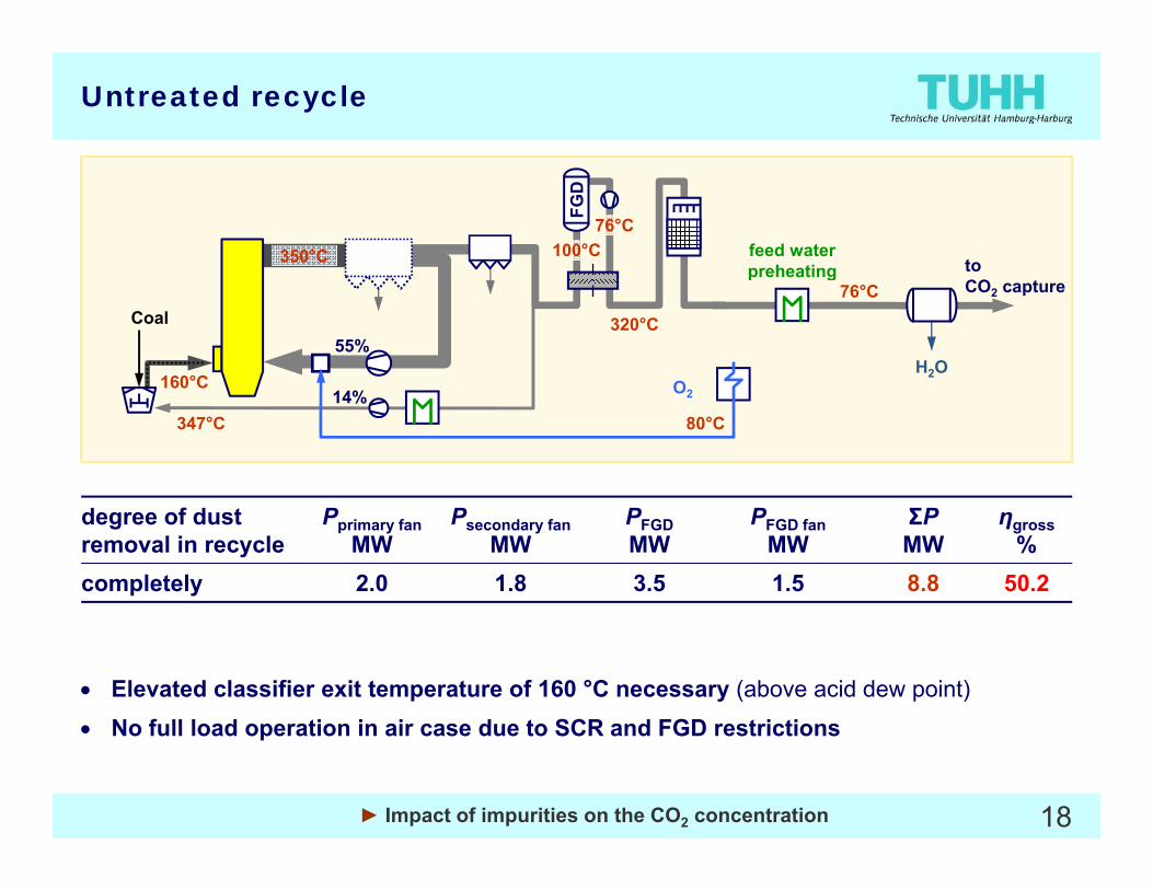
Untreated recycle
to100°C feed water
preheating
FGD
76°C
350°C
76°C
H2O
CO2 capture
O
Coal
preheating
160°C
320°C55%
O214%347°C 80°C
degree of dust removal in recycle
Pprimary fanMW
Psecondary fanMW
PFGDMW
PFGD fanMW
ΣPMW
ηgross%
completely 2.0 1.8 3.5 1.5 8.8 50.2
• Elevated classifier exit temperature of 160 °C necessary (above acid dew point)
• No full load operation in air case due to SCR and FGD restrictions
18
• No full load operation in air case due to SCR and FGD restrictions
► Impact of impurities on the CO2 concentration
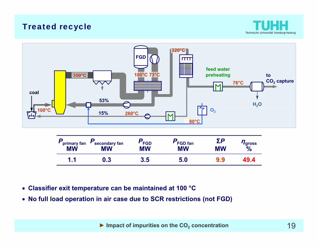
Treated recycle
350°C
320°C
feed water preheating to100°C
FGD
73°C
H2O
coal53%
350 C76°C
preheating toCO2 capture
260°C15%100°C
P P P P ΣP
O2
80°C
Pprimary fanMW
Psecondary fanMW
PFGDMW
PFGD fanMW
ΣPMW
ηgross%
1.1 0.3 3.5 5.0 9.9 49.4
• Classifier exit temperature can be maintained at 100 °C• No full load operation in air case due to SCR restrictions (not FGD)
19
No full load operation in air case due to SCR restrictions (not FGD)
► Impact of impurities on the CO2 concentration
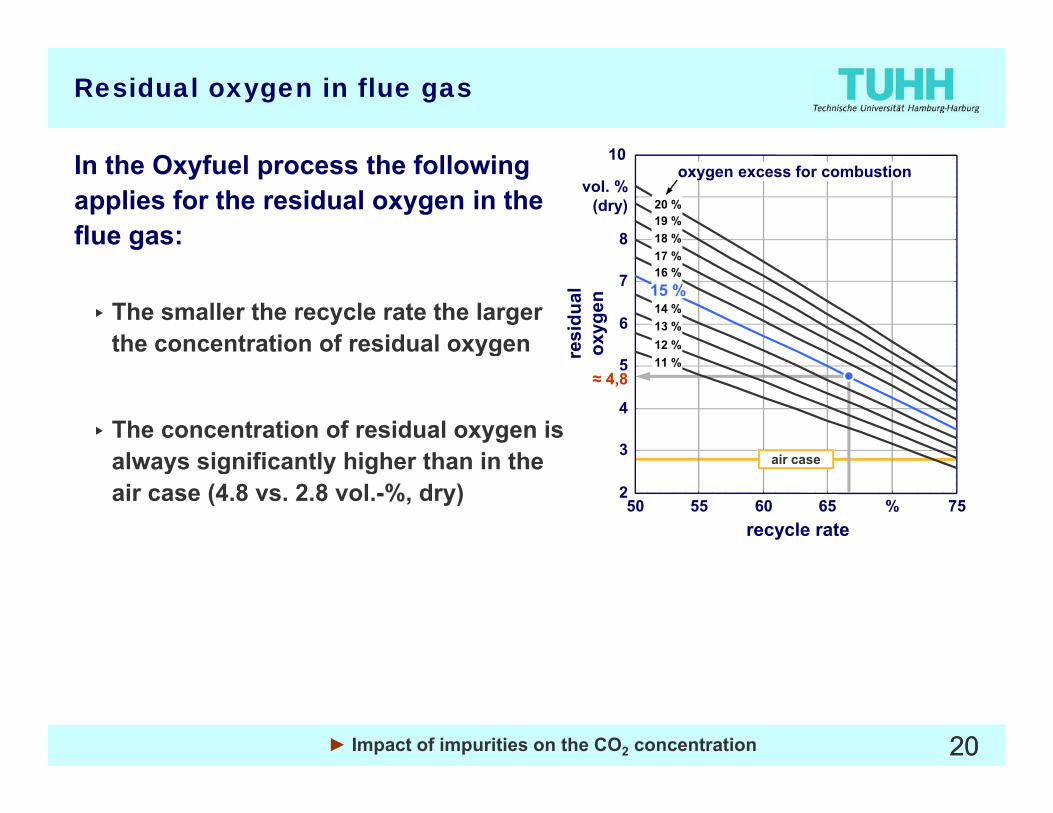
Residual oxygen in flue gas
10In the Oxyfuel process the following applies for the residual oxygen in the flue gas:
10
8
vol. %(dry)
17 %18 %19 %20 %
oxygen excess for combustion
▸ The smaller the recycle rate the larger the concentration of residual oxygen
6
7
12 %13 %14 %15 %16 %17 %
resi
dual
ox
ygen
yg
▸ The concentration of residual oxygen is always significantly higher than in the 3
4
5 11 %r
≈ 4,8
air casealways significantly higher than in the air case (4.8 vs. 2.8 vol.-%, dry) 50 55 60 65 % 75
2
recycle rate
air case
2020► Impact of impurities on the CO2 concentration
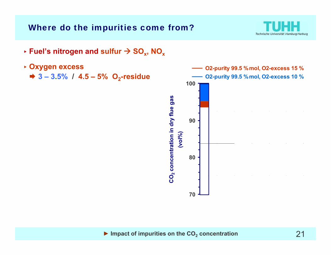
Where do the impurities come from?
O2-purity 95.0 %mol, O2-excess 15 % O2-purity 98.0 %mol, O2-excess 15 % O2-purity 99.5 %mol, O2-excess 15 % O2-purity 99.5 %mol, O2-excess 10 %
▸ Fuel’s nitrogen and sulfur SOx, NOx
▸Oxygen excess3 – 3.5% / 4.5 – 5% O2-residue
100
ue g
as
p y ,
Durch konstruktive Maßnahmen zu erzielender
2
90
tion
in d
ry fl
uvo
l%)
Falschluftanteil
80
O2 c
once
ntra
t (v
700 1 2 3 4 5 6
CO
Air leakage as % of flue gas (wet basis)
21► Impact of impurities on the CO2 concentration

Where do the impurities come from?
O2-purity 95.0 %mol, O2-excess 15 % O2-purity 98.0 %mol, O2-excess 15 % O2-purity 99.5 %mol, O2-excess 15 % O2-purity 99.5 %mol, O2-excess 10 %
▸ Fuel’s nitrogen and sulfur SOx, NOx
▸Oxygen excess3 – 3.5% / 4.5 – 5% O2-residue
100
ue g
as
p y ,
Durch konstruktive Maßnahmen zu erzielender
2
▸ Air separation unit98% O2-purity: 2% Ar
90
tion
in d
ry fl
uvo
l%)
Falschluftanteil95% O2-purity: 3.8% Ar + 1.2% N2
80
O2 c
once
ntra
t (v
700 1 2 3 4 5 6
CO
Air leakage as % of flue gas (wet basis)
22► Impact of impurities on the CO2 concentration

Energy demand for ASU and CO2 separation
Boundary conditions: capture rate = 90 %, CO2-purity > 96%, 87 % of oxygen delivered by ASU, South African hard coal, 2 % leakage air
14 %
10 %
12 %
poin
ts
CPU ASU
6,9 %
5 5 %
3,9 %
4,1 %4,1 %6 %
8 %
ncy l
oss
in %
-p
5,5 %4,4 %
2 %
4 %
effic
ien
O2 purity - ASU technology
0 %99,5%-conventional 95% - multi reboiler 95% - multi column
23
Overall net efficiency increase by decreased O2 purity by approx. 2.3 %-points
► Impact of impurities on the CO2 concentration

Where do the impurities come from?
O2-purity 95.0 %mol, O2-excess 15 % O2-purity 98.0 %mol, O2-excess 15 % O2-purity 99.5 %mol, O2-excess 15 % O2-purity 99.5 %mol, O2-excess 10 %
▸ Fuel’s nitrogen and sulfur SOx, NOx
▸Oxygen excess3 – 3.5% / 4.5 – 5% O2-residue
100
ue g
as
p y ,
Durch konstruktive Maßnahmen zu erzielender
2
▸ Air separation unit98% O2-purity: 2% Ar
90
tion
in d
ry fl
uvo
l%)
Falschluftanteil95% O2-purity: 3.8% Ar + 1.2% N2
80
O2 c
once
ntra
t (v
700 1 2 3 4 5 6
CO
Air leakage as % of flue gas (wet basis)
24► Impact of impurities on the CO2 concentration

Where do the impurities come from?
▸ Fuel’s nitrogen and sulfur SOx, NOx
▸Oxygen excess3 – 3.5% / 4.5 – 5% O2-residue
O2-purity 95.0 %mol, O2-excess 15 % O2-purity 98.0 %mol, O2-excess 15 % O2-purity 99.5 %mol, O2-excess 15 % O2-purity 99.5 %mol, O2-excess 10 %2
▸ Air separation unit98% O2-purity: 2% Ar
100
ue g
as
Air Leakage95% O2-purity: 3.8% Ar + 1.2% N2
▸ Air leakageapprox 3 % of flue gas flow for
90
tion
in d
ry fl
uvo
l%)
Air Leakage
approx. 3 % of flue gas flow fora new conventional power plantup to 10 % over the years forpower plants in use
80
O2 c
once
ntra
t (vp p
Air leakage is a major source of impurities and needs to be
d d b i t d i
700 1 2 3 4 5 6
CO
25
reduced by appropriate design Air leakage as % of flue gas (wet basis)
► Impact of impurities on the CO2 concentration

Impurities in the Flue Gas
• N2, Ar▸ Sources: oxygen, air ingress,…
▸ Inert components which have no significant impact underground▸ Inert components which have no significant impact underground
▸ Increase auxiliary power demand for liquefaction of the CO2(as shown above this is not very much)
▸ Removing them during air separation (to achieve purer O2)increases the auxiliary power demand of the air separation unit (as shown above this is very much)
Need for optimization between air separationand CO2 liquefaction (considering also air leakage)
2626► Impact of impurities on the CO2 concentration
Impurities in the Flue Gas
• O2, NOX, SO2 ,CO , Hg, Cl▸ May negatively influence the geological storage site by causing
geochemical reactions or the transport in pipelinesg p p p
The maximum permissible concentrations for these impuritiesare still to be defined
27► Impact of impurities on the CO2 concentration

CO2 purity
Introduction• Introduction
▸What are the barriers for a successful deployment of the OxyfuelProcess?
▸Why considering the impurities?
• General Boundary Conditions of the Oxyfuel Process
▸Flue gas recycle demand; O2 excess; O2 concentration
• Impact of Impurities on the CO2 Concentration
▸Where do the impurities come from?
• R&D Project COORAL
▸Definition of required CO2 purity
• Possibilities to increase CO2 Purity
28

Project COORAL
COORALCO2-Reinheit für Abtrennung und Lagerung
(CO2 purity for capture and storage)
• Partners:
▸ BGR, BAM, DBI, MLU, TUHH
▸ Industry: Alstom, E.ON, Vattenfall, EnBW, VNG
• Includes the whole CO chain from production to storage:• Includes the whole CO2 chain from production to storage:
Transport Injektion
I II III
Production
Storage
IV
29
Storage
► R&D project COORAL

COORAL - Objectives
• Estimation of impurities in CO2 (Post-Combustion, Oxyfuel, Pre-Combustion)
• Possibilities to influence the CO2 impurities by
▸ operation of the power plant▸ operation of the power plant
▸ CO2 separation processes (Post-Combustion, Oxyfuel, Pre-Combustion)
▸ CO2 treatment (mainly Oxyfuel)
• Examination of the effects caused by impurities on
▸ the transport chain
▸ the injection chain
▸ the geological site (geochemical reactions)
O ti i ti b t i d l t ifi d d• Optimisation between economic and plant-specific demands
Definition of the req ired CO p rit for capt re and storage
30
Definition of the required CO2 purity for capture and storage
► R&D project COORAL

Expected impurities in separated CO2
Component Post-Combustion Oxyfuel Pre-CombustionN2 Yes Yes YesN2 Yes Yes YesO2 Yes Yes (Yes)Ar Yes Yes YesH2O Yes Yes YesNO Y Y NNOX Yes Yes NoSOX Yes Yes NoNH3 Yes No NoHg, . . . No Yes YesgH2 No No YesH2S No No YesHCN No No YesCH No No YesCH4 No No YesCO Yes Yes YesCOS No No YesResidues from Washing Yes No Yes
31► R&D project COORAL

Scenarios of Expected Impurities - Post-Combustion
• Post I
▸ 99,93 Vol.-% CO2
• Post II
▸ 99,92 Vol.-% CO2
• Post III
▸ 99,81 Vol.-% CO2
▸ 150 ppm O2
▸ 450 ppm N2 + Ar
20 NO
▸ 150 ppm O2
▸ 450 ppm N2 + Ar
20 NO
▸ 300 ppm O2
▸ 900 ppm N2 + Ar
40 NO▸ 20 ppm NOX
▸ 10 ppm SO2
▸ 100 ppm H2O
▸ 20 ppm NOX
▸ 10 ppm SOX
▸ 100 ppm H2O
▸ 40 ppm NOX
▸ 20 ppm SOX
▸ 600 ppm H2O100 ppm H2O
▸ 10 ppm CO
100 ppm H2O
▸ 10 ppm CO
▸ 50 ppm NH3 *
600 ppm H2O
▸ 20 ppm CO
32
* approximation.
► R&D project COORAL

Scenarios Expected Impurities - Pre-Combustion
• Selexol
▸ 97,95 Vol.-% CO2
• Rectisol
▸ 99,7 Vol.-% CO2
▸ 1,0 Vol.-% H2
▸ 0,9 Vol.-% N2
300 A
▸ 20 ppm H2
▸ 0,21 Vol.-% N2
150 A▸ 300 ppm Ar
▸ 100 ppm H2S + COS
▸ 600 ppm H2O
▸ 150 ppm Ar
▸ 20 ppm H2S + COS
▸ 10 ppm H2Opp 2
▸ 400 ppm CO
▸ 100 ppm CH4
pp 2
▸ 400 ppm CO
▸ 100 ppm CH4
▸ 200 ppm Methanol
33► R&D project COORAL

Scenarios of Expected Impurities - Oxyfuel
• Oxyfuel I
(Zero Emission)
85 0 V l % CO
• Oxyfuel II • Oxyfuel IV
(Distillation)
99 94 V l % CO
• Oxyfuel III
(Concentration)
98 0 % CO▸ 85,0 Vol.-% CO2
▸ 4,70 Vol.-% O2
▸ 5,80 Vol.-% N2
▸ 99,94 Vol.-% CO2
▸ 100 ppm O2
▸ 100 ppm N2
▸ 98,0 % CO2
▸ 0,67 % O2
▸ 0,71 % N2, 2
▸ 4,47 Vol.-% Ar
▸ 100 ppm NOX
pp 2
▸ 100 ppm Ar
▸ 100 ppm NOX
, 2
▸ 0,59 % Ar
▸ 100 ppm NOX
▸ 50 ppm SO2
▸ 20 ppm SO3
▸ 100 ppm H O
▸ 50 ppm SO2
▸ 20 ppm SO3
▸ 100 ppm H O
▸ 50 ppm SO2
▸ 20 ppm SO3
▸ 100 ppm H O▸ 100 ppm H2O
▸ 50 ppm CO
▸ 100 ppm H2O
▸ 50 ppm CO
▸ 100 ppm H2O
▸ 50 ppm CO
34► R&D project COORAL

CO2 purity
Introduction• Introduction
▸What are the barriers for a successful deployment of the OxyfuelProcess?
▸Why considering the impurities?
• General Boundary Conditions of the Oxyfuel Process
▸Flue gas recycle demand; O2 excess; O2 concentration
• Impact of Impurities on the CO2 Concentration
▸Where do the impurities come from?
• R&D Project COORAL
▸Definition of required CO2 purity
• Possibilities to increase CO2 Purity
35
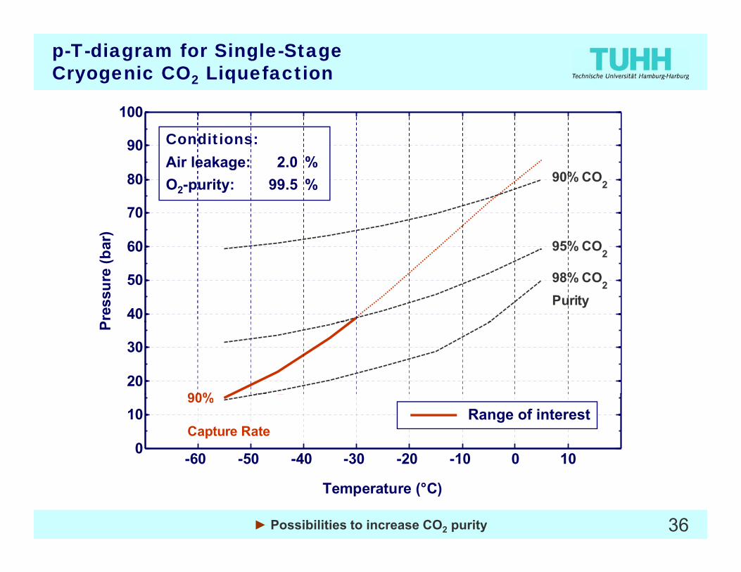
p-T-diagram for Single-StageCryogenic CO2 Liquefaction
80
90
100
80
90
100
90% CO80
90
100
90% CO80
90
100
90% CO80
90
100
90% CO80
90
100
90% CO
Conditions:Air leakage: 2.0 %
60
70
80
ar)
60
70
80
ar)
90% CO2
95% CO260
70
80
ar)
90% CO2
95% CO260
70
80
ar)
90% CO2
95% CO260
70
80
ar)
90% CO2
95% CO260
70
80
ar)
90% CO2
95% CO2
O2-purity: 99.5 %
40
50
60
Pres
sure
(b
40
50
60
Pres
sure
(b
Purity
95% CO2
98% CO2
40
50
60
Pres
sure
(b
Purity
95% CO2
98% CO2
40
50
60
Pres
sure
(b
Purity
95% CO2
98% CO2
40
50
60
Pres
sure
(b
Purity
95% CO2
98% CO2
40
50
60
Pres
sure
(b
Purity
95% CO2
98% CO2
20
30
P
20
30
P
20
30
P
90%20
30
P
90%
95%20
30
P
90%20
30
P
90%
-60 -50 -40 -30 -20 -10 0 100
10Capture Rate80%
-60 -50 -40 -30 -20 -10 0 100
10Capture Rate80%
-60 -50 -40 -30 -20 -10 0 100
10Capture Rate80%90%
-60 -50 -40 -30 -20 -10 0 100
10Capture Rate80%90%
-60 -50 -40 -30 -20 -10 0 100
10Capture Rate
90%
-60 -50 -40 -30 -20 -10 0 100
10Capture Rate
90%Range of interest
36
Temperature (°C)
► Possibilities to increase CO2 purity
Temperature (°C)Temperature (°C)Temperature (°C)Temperature (°C)Temperature (°C)

Impact of distillation on overall power demand for CO2 capture
C id t i i i l
ure in M
W
• Consider a certain minimal temperature level (e. g. -40 °C):
▸higher flue gas pressure
or CO
2captu▸higher flue gas pressure
necessary to achieve a similar CO2 capture rate
er dem
and fo▸ increase in power demand
Overall po
we
• The additional distillation reduces the efficiency of the overall power plant process by
CO2 capture rate
Ooverall power plant process by 0.2 %-pts. for a capture rate of 90 %.
37► Possibilities to increase CO2 purity
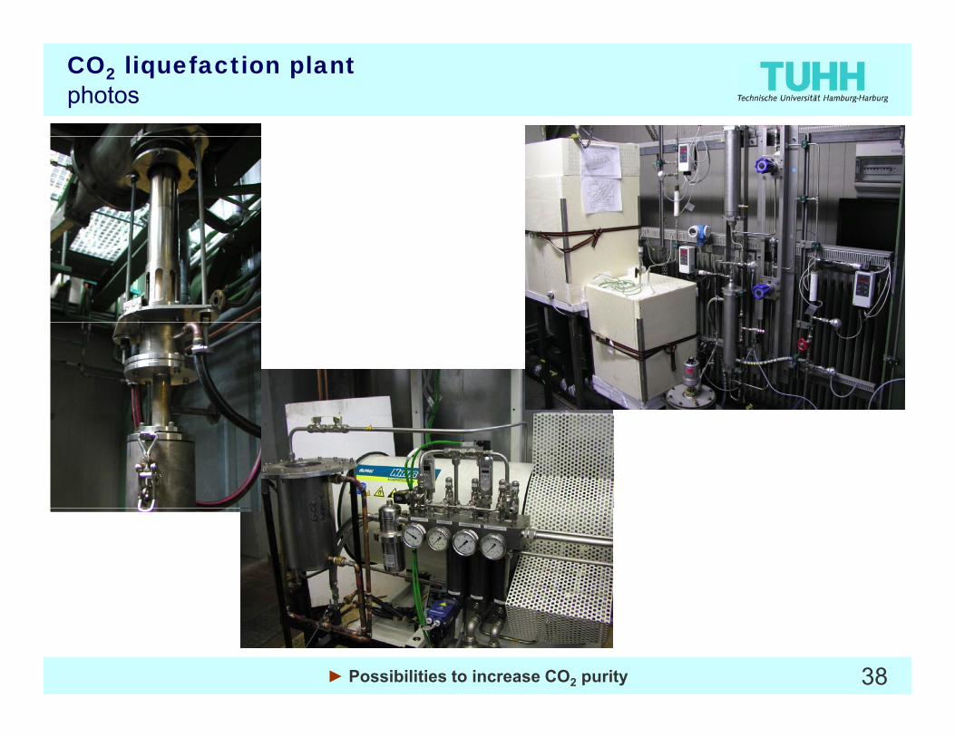
CO2 liquefaction plantphotos
38► Possibilities to increase CO2 purity

Experiments with Oxyfuel flue gas
60
7093%
95%2 phase region
• Oxyfuel Flue Gas:Combustion of hard coal in CO2
50
60 95%
96%
97%
95%
90%
80%mixture with 30 %vol O2, residual oxygen ~4 %vol
• Experiments at different
30
40
p in
bar 98%
95%
dew point curve
Experiments at different pressure and temperature conditions
C iti f d
10
20
capture ratepurity of liquid CO2
vapor
▸Composition of vapour and liquid phase
▸Experimental experience
0-60 -50 -40 -30 -20 -10 0 10
T in °C
purity of liquid CO2Experiments
p p
▸Sulphur and nitrous components
39► Possibilities to increase CO2 purity
CO2 purity
Introduction• Introduction
▸What are the barriers for a successful deployment of the OxyfuelProcess?
▸Why considering the impurities?
• General Boundary Conditions of the Oxyfuel Process
▸Flue gas recycle demand; O2 excess; O2 concentration
• Impact of Impurities on the CO2 Concentration
▸Where do the impurities come from?
• R&D Project COORAL
▸Definition of required CO2 purity
• Possibilities to increase CO2 Purity
40Thank you for your attention!
CO Quality and Other CO2 Quality and Other Relevant Issues
Oxyfuel Process(Post-Combustion Capture)(Pre-Combustion Capture)
Institute ofEnergy Systems
Introduction and Objectives of the Meeting
Th k f A. Kather
Energy Systems
Thank you for your attention!
Hamburg University of Technology
2nd Working Group Meeting on CO2 Quality and Other Relevant Issues
7th September 2009, Cottbus