Pittsburgh & Lake Erie R. Co. v. Railway Labor Executives' Assn., 491 U.S. 490 (1989)

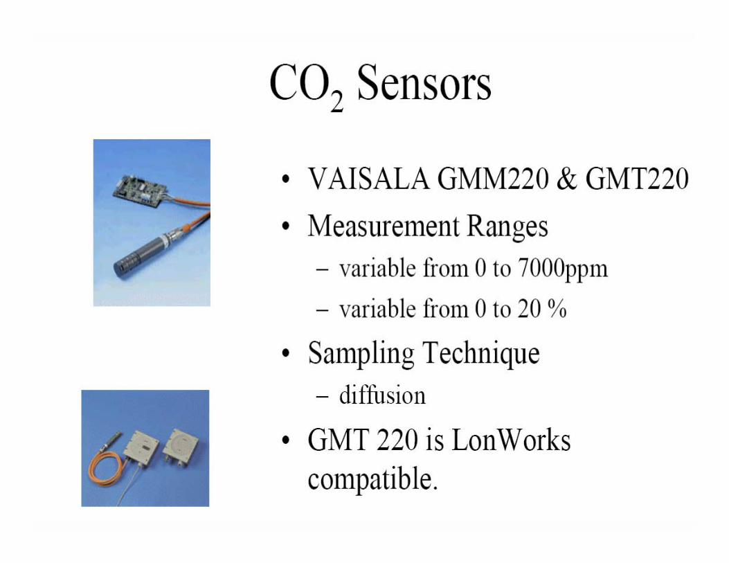
CO2 SENSORS
Project PresentationSINAN ATABEK
ME 2082 Principle of Electromechanical Sensors and Actuators

Introduction• Why measure CO2 ?• - If levels become to high CO2 begins to act as
asphyxiant.- A general indicator of indoor air quality.- High levels can enhance plant growth.
• Place that CO2 sensors are used?- Confined work spaces.- Brewing and carbonated drink industries.- Controlled plant growth.- Photosynthesis. - Fermentation.- Aerobic respiration.

Types of CO2 Sensors• Mass Airflow sensors
- thermal conductivity• Solid state electrochemical sensors• Mixed oxide sensors• Ion selective membrane sensors• Optical sensors

Mass Airflow Sensors• Mass airflow sensors contain a
thin-film, thermally isolated bridge structure containing heater and temperature sensing elements. The bridge structure provides a sensitive and fast response to the flow of air or other gas over the chip.
• State-of-the-art chip design and manufacturing techniques allow the micro bridge to be remarkably sensitive, fast, small. Usedwherever airflow needs to be measured.
• Typical applications; Air pollution instrumentation, HVAC damper control, Gas analyzers, medical equipment, Process control

Solid state electrochemical sensors
The most popular sensing method for toxic gases and oxygen monitoring. Not used for combustible gas monitoring. This is the best all around sensor for ambient toxic gas monitoring. It is simple, reliable and inexpensive. The disadvantage apply mainly in atypical applications. Solid state sensors can detect most chemicals in the LEL ranges. For toxic gas applications, it is generally favorable to use solid state sensors, especially when the number of sensors is sizable.

Carbon dioxide optical sensor• Concentration range 0-999 ppm• Typical sensitivity (-30,+30) ppm• Temperature up to 300 C• Response time 10 s
Side view of the CO2 sensor: lon the left, the pyroelectric detector with encapsulated porous silicon
microcavity centered at 4257 nm, on the right the IR source.

Sensor method
• Single beam absorption infrared
Sensor scheme
scheme Sensor

Principle of operationThe light intensity which reaches the pyroelectric detector is correlated to the concentration of carbon dioxide. CO2 variation are detected by measuring the voltage between the two armours of the pyroelectric detector which is proportional to the light intensity. Three main components make up the carbon dioxide sensor: a commercial pulsable infrared emitters, a pyroelectric detector and a porous silicon
optical filter
Front view of detector and of the PS microcavity
The optical filter consisting of alternating porous silicon layers of different refractive indexes represents the sensing element. The optical filter is projected to selectively allow the propagation of a single wavelength 4257nm, i.e. absorption wavelength of the fundamental vibration of carbon dioxide molecule. The optical filter is allocated on top of the pyroelectric detector.

SEM microphoto of a cross section of the porous silicon optical filter


Why optical method?
• Inert nature of CO2 makes it difficult to measure with sensors that depend on chemical reactions.
• Optical sensors are not affected by dust, water vapor or most chemicals.


Refrences• http://faculty.uca.edu/~march/bio1/aer_resp/c
o2_sensor.htm• http://www.checs.ien.it• http://www.vaisala.com
• www.honeywell.com• www.delphian.com• www.intlsensor.com