CNC fabricated formwork for a UHPFRC thin folded plate … · CNC-fabricated formwork for a UHPFRC...
8
IABSE Conference – Structural Engineering: Providing Solutions to Global Challenges September 23-25 2015, Geneva, Switzerland 1 CNC-fabricated formwork for a UHPFRC thin folded plate arch Paul Mayencourt, Christopher Robeller, Yves Weinand Laboratory for Timber Construction (IBOIS), École Polytechnique Fédérale de Lausanne, Switzerland Christophe Loraux, Eugen Brühwiler Laboratory of Maintenance and Safety of Structures (MCS), École Polytechnique Fédérale de Lausanne, Switzerland Contact: [email protected], [email protected] Abstract Folded plate structures or shells are statically efficient structures. However, their construction is limited by the complexity and cost of their formwork. We used Computer Numerical Control Milling Technology to design a wooden formwork for an Ultra-High Performance Fibre Reinforced cement-based Composite (UHPFRC) folded plate arch. This paper describes the design and assembly of a formwork made from cross-laminated veneer lumber panels (LVL) with integrated wood-wood connections and the testing of the resulting thin origami-like UHPFRC arch. Currently achieved for a lab scale, CNC wood milling technology combined with integrated panel joints could enable mass-customized formwork for complex structures. UHPFRC is probably the only existing material with required strength and sustainability properties for ultra-thin structures. However, special attention should be given to the casting direction and fibres orientation in sharp edges. Based on this consideration and the result of the first lab test, some geometric adjustments and construction details are proposed and discussed in this paper. Keywords: timber folded plates shell, Ultra-high performance fibre reinforced cement-based composite (UHPFRC), CNC-fabricated formwork, integral mechanical attachment, digital fabrication 1 Introduction Folded plate thin shells are statically efficient and stiff structural systems to cover large spans with a minimal amount of material. However, they are complex and expensive to realize in concrete with conventional formwork techniques. The high labour cost of formwork reduces the competitiveness of using relatively cheap wood panels for casting. Recent developments in wood panels jointing techniques and Computer Numerical Control (CNC) technology enable the construction of timber folded plate structures [1][2]. Firstly, the new integrated mechanical attachment technique for panel edgewise connection allows rapid and precise assembly of panel elements without metal fasteners. Second, digital fabrication makes it possible to customize every structural element without extra fabrication time and cost.
Transcript of CNC fabricated formwork for a UHPFRC thin folded plate … · CNC-fabricated formwork for a UHPFRC...

IABSE Conference – Structural Engineering: Providing Solutions to Global Challenges September 23-25 2015, Geneva, Switzerland
1
CNC-fabricated formwork for a UHPFRC thin folded plate arch
Paul Mayencourt, Christopher Robeller, Yves Weinand
Laboratory for Timber Construction (IBOIS), École Polytechnique Fédérale de Lausanne, Switzerland
Christophe Loraux, Eugen Brühwiler
Laboratory of Maintenance and Safety of Structures (MCS), École Polytechnique Fédérale de Lausanne, Switzerland
Contact: [email protected], [email protected]
Abstract
Folded plate structures or shells are statically efficient structures. However, their construction is limited by the complexity and cost of their formwork. We used Computer Numerical Control Milling Technology to design a wooden formwork for an Ultra-High Performance Fibre Reinforced cement-based Composite (UHPFRC) folded plate arch. This paper describes the design and assembly of a formwork made from cross-laminated veneer lumber panels (LVL) with integrated wood-wood connections and the testing of the resulting thin origami-like UHPFRC arch. Currently achieved for a lab scale, CNC wood milling technology combined with integrated panel joints could enable mass-customized formwork for complex structures. UHPFRC is probably the only existing material with required strength and sustainability properties for ultra-thin structures. However, special attention should be given to the casting direction and fibres orientation in sharp edges. Based on this consideration and the result of the first lab test, some geometric adjustments and construction details are proposed and discussed in this paper.
Keywords: timber folded plates shell, Ultra-high performance fibre reinforced cement-based composite (UHPFRC), CNC-fabricated formwork, integral mechanical attachment, digital fabrication
1 Introduction
Folded plate thin shells are statically efficient and stiff structural systems to cover large spans with a minimal amount of material. However, they are complex and expensive to realize in concrete with conventional formwork techniques. The high labour cost of formwork reduces the competitiveness of using relatively cheap wood panels for casting.
Recent developments in wood panels jointing techniques and Computer Numerical Control (CNC) technology enable the construction of timber folded plate structures [1][2]. Firstly, the new integrated mechanical attachment technique for panel edgewise connection allows rapid and precise assembly of panel elements without metal fasteners. Second, digital fabrication makes it possible to customize every structural element without extra fabrication time and cost.

IABSE Conference – Structural Engineering: Providing Solutions to Global Challenges September 23-25 2015, Geneva, Switzerland
2
Ultra High Performance Fibre Reinforced Cement-based Composite (UHPFRC) used until now to strengthen and rehabilitate existing concrete structures, is recently positioning itself as a high-tech material for the construction of thin shells [3].
This paper explores possibilities to use timber integrated mechanical connection (theme investigated by IBOIS) to cast thin UHPFRC (theme investigated by MCS) shells. The first part of the paper shows the timber folded plate formwork, the use of the integrated wood-wood connections and the UHPFRC material technology. In the second part the fabrication of the formwork and the thin shell prototype is described. Finally, the results of the load test and project’s outcomes are discussed.
2 Formwork Concept
This chapter presents the design of the timber folded plate structure, the panel edgewise connections and the general use of UHPFRC and its application for thin shells.
2.1 Timber Interlocking folded plate and integrated mechanical attachment
Structural wood veneer panels (LVL) are an increasingly popular product used in prefabricated timber constructions. The panels combine the favorable weight-to strength ratio, carbon dioxide storage and easy machining of wood, with the dimensional stability of multi-layered laminated panels.
In its early applications, plywood was mostly used for the cross-bracing of timber frame constructions. The panels were connected to the timber frame, but joints between the panels were not needed. In recent years however, prefabricated building components, such as wall elements or self-supporting ceiling and roof components (up to a width of 14 m) are being produced entirely from LVL panels, which are typically 27-45 mm thick. These new applications require direct edgewise joints between the plates.
For such standardized, rectangular applications, standard joints such as self-tapping wood screws in the side faces of the plates, or alternatively metal plate brackets, joist hangers and plates can be used.
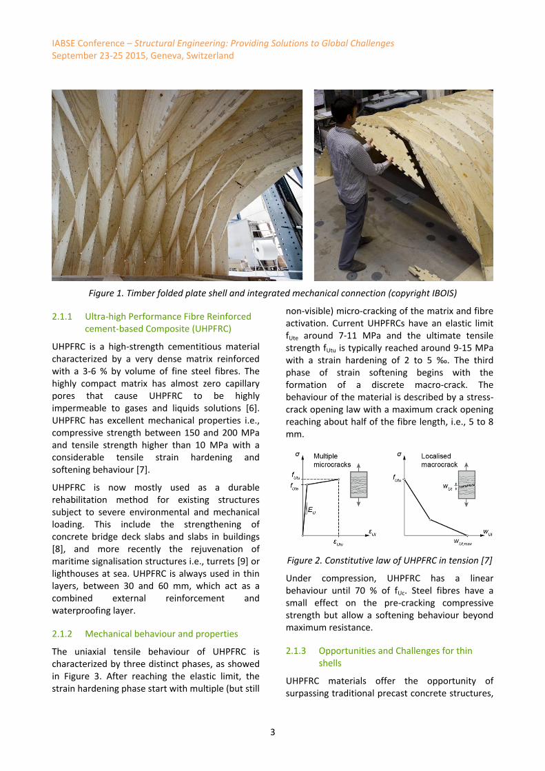
A more challenging application for LVL panels is being presented by several experimental surface-active structures [1][4], which aim at the use of the wood panels for the sustainable construction of lightweight and structurally efficient curved shells.
In these structures, large numbers of plate components must be jointed at various, non-orthogonal dihedral angles. Inspired by traditional Japanese woodworking joinery, C. Robeller [5] proposed to use a CAD application programing interface (API), in order to automatically generate geometrically variable dovetail joints, which will serve not only as load-bearing connectors between the plates, but also as “locators”, where the information for the fast and precise assembly of the CNC-fabricated joints is “embedded” in the form of the connection.
In addition to the previously demonstrated use of this technique for the construction of timber plate structures, this paper investigates a possible application for the rapid, precise and cost-efficient production and assembly of free-form UHPFRC formwork, without the need for large additional support structures.
The design of the prototype has been carried out with respect to certain constraints that result from the fabrication and assembly of the joints. For example, the dihedral angles between plates were constrained to 50°-130°. The requirements were satisfied by a reverse-folded assembly of quadrilateral faces, similar to the Japanese “Miura Ori” paper folds and the “antiprismatic shells” studied in the 1960s [6][7].
Additionally, the design of the UHPFRC formwork required a double-layered construction, where all plates are offset at a constant thickness of 20 mm.
IABSE Conference – Structural Engineering: Providing Solutions to Global Challenges September 23-25 2015, Geneva, Switzerland
3
Figure 1. Timber folded plate shell and integrated mechanical connection (copyright IBOIS)
2.1.1 Ultra-high Performance Fibre Reinforced cement-based Composite (UHPFRC)
UHPFRC is a high-strength cementitious material characterized by a very dense matrix reinforced with a 3-6 % by volume of fine steel fibres. The highly compact matrix has almost zero capillary pores that cause UHPFRC to be highly impermeable to gases and liquids solutions [6]. UHPFRC has excellent mechanical properties i.e., compressive strength between 150 and 200 MPa and tensile strength higher than 10 MPa with a considerable tensile strain hardening and softening behaviour [7].
UHPFRC is now mostly used as a durable rehabilitation method for existing structures subject to severe environmental and mechanical loading. This include the strengthening of concrete bridge deck slabs and slabs in buildings [8], and more recently the rejuvenation of maritime signalisation structures i.e., turrets [9] or lighthouses at sea. UHPFRC is always used in thin layers, between 30 and 60 mm, which act as a combined external reinforcement and waterproofing layer.
2.1.2 Mechanical behaviour and properties
The uniaxial tensile behaviour of UHPFRC is characterized by three distinct phases, as showed in Figure 3. After reaching the elastic limit, the strain hardening phase start with multiple (but still
non-visible) micro-cracking of the matrix and fibre activation. Current UHPFRCs have an elastic limit fUte around 7-11 MPa and the ultimate tensile strength fUtu is typically reached around 9-15 MPa with a strain hardening of 2 to 5 ‰. The third phase of strain softening begins with the formation of a discrete macro-crack. The behaviour of the material is described by a stress-crack opening law with a maximum crack opening reaching about half of the fibre length, i.e., 5 to 8 mm.
Figure 2. Constitutive law of UHPFRC in tension [7]
Under compression, UHPFRC has a linear behaviour until 70 % of fUc. Steel fibres have a small effect on the pre-cracking compressive strength but allow a softening behaviour beyond maximum resistance.
2.1.3 Opportunities and Challenges for thin shells
UHPFRC materials offer the opportunity of surpassing traditional precast concrete structures,

IABSE Conference – Structural Engineering: Providing Solutions to Global Challenges September 23-25 2015, Geneva, Switzerland
4
mainly by excluding the need of steel rebars. Extremely thin precast UHPFRC shells provide then weight reduction, tight construction tolerance and speed of construction, excellent finishes and waterproofing. It drastically increases durability and sustainability of these structures and by the same time reduces cost and maintenance. However, special attention must be given to thickness control and fibre orientation in the matrix. The shape of the formwork and the casting direction influence the fibre orientation. Knowing these parameters and performing adequacy tests, one can easily overcome this limitation.
3 UHPFRC thin folded plate shell prototype
The prototype brings all the advantages together: cut of complex geometries with timber panels and integrated connections for rapid assembly with the strength and continuity of UHPFRC. In order to cast the thin UHPFRC shell, two timber folded plates are fabricated. The 20 mm gap between the two shells corresponds to the space left for pouring the fresh matrix. The shell spans 1.65 m for a height of 0.69 m and is 0.45 m wide.
3.1.1 Material
For this first prototype of UHPFRC shell, an industrial premix by Holcim, H707, is used. It contains a high dosage in cement and mineral adjuncts, has 3.0 % vol. straight smooth steel fibres (length 13 mm, diameter 0.16 mm) and a water/cement ratio around 0.17. Workability of the fresh mix is optimized with the use of superplasticizer. The arch represents a volume of 26 litres of UHPFRC for a weight of 63 kg.
This UHPFRC mix was previously submitted to a material characterisation campaign [10]. Average properties are given in Table 1.
Table 1. UHPFRC properties at 28 days
Elastic
Strain Hardening
EUm [GPa]
fUc [MPa]
fUte [MPa]
ɛUtu [‰]
fUtu [MPa]
44.5 151 6.6 1.2 7.5
For the timber formwork we used 15 mm beech wood panel with special coating “Form” from Metsäwood.
3.1.2 Construction and Assembly
For the production of our prototype we used a MAKA MM7s 5-axis router. The geometry of the shell is created in Rhino3D. From the shell geometry, an algorithm writes the cutting code for the panels and the integrated connection to be transferred to the CNC-router. After the panel are cut, it takes approximately half an hour to assemble one shell. The two shells are then assembled together and the fresh UHPFRC is poured from the side. The thickness of the gap was maintained by the stiffness of the folded plate construction and stiffener added on the side opening.
Screws are used in order to tightly close the gap of the panel connection. Moreover, security tape is applied on all the inner edges to avoid leaking of cement paste through the fabrication gaps. On the inner surface of the formwork, panels are coated with oil to limit adherence of the UHPFRC mix.
Figure 3. Construction of the formwork (copyright IBOIS)

IABSE Conference – Structural Engineering: Providing Solutions to Global Challenges September 23-25 2015, Geneva, Switzerland
5
Figure 4. Casting of the shell (copyright IBOIS)
3.2 Final shell
The resulting shell has a nice and smooth surface and angle quality, with very few imperfections. The formwork was removed without problem and can be re-used for a next prototype.
Figure 5. Inner side of the UHPFRC arch (copyright IBOIS)
4 Shell load test and numerical analysis
A load test was performed on the UHPFRC shell in order to determine the behaviour and the ultimate strength of this complex geometry. The structure was instrumented with 7 Linear Variable Displacement Transducer (LVDT’s) to measure the horizontal and vertical displacement, and 2 local strain gages with a 50 mm measuring base were installed on two faces under the middle of the arch. The arch was loaded with a 250 kN displacement controlled actuator until failure. The displacement was imposed on the top edges through a steel plate. Lead layers were arranged between the arch and the steel plate to ensure uniform application of force. Wood panels cut to the exact shape of the arch were disposed at the support to lock the lateral displacement and allow rotation.
Figure 6. Force-deflection diagram
0
5
10
15
20
25
30
0 5 10 15 20 25 30
Load
F [
kN]
Top deflection δ [mm]
Experiment
FEM model

IABSE Conference – Structural Engineering: Providing Solutions to Global Challenges September 23-25 2015, Geneva, Switzerland
6
The force-deflection diagram is shown on Figure 6. After a short elastic phase, multiple micro-cracks appear uniformly on the inner top edges under positive bending and on the outer edges under the effect of negative bending. These micro-cracks are not visible to the naked eye (opening less than 0.1 mm) and are revealed by spraying alcohol on the UHPFRC. The first visible (opening of 0.2 mm) crack appeared on the inner top edges, after a vertical displacement of 5 mm. At around a displacement of 10 mm, a macro-crack with an opening of 0.2 mm located on the weakest side of the arch, resulting in the closure of micro-cracks appeared previously. The load continued to increase despite the large opening of the two cracks (Fig. 7). Up to an opening of 4 mm, both cracks still transmitted tensile stresses resulting in a very ductile structure. The ultimate force Fmax = 26 kN is reached at a deformation of l/100. The
force significantly drops with the creation of two plastic hinges. The ultimate displacement is reached at around l/50, a common value for
failure of arches due the formation of 4 hinges.
Figure 7. Final crack on the outer edge (left) and final crack at the inner to inner face (right)
(copyright MCS)
A non-liner finite element analysis was performed with the commercial code DIANA 9.4.4 [13] to estimate the maximum force. A smeared multi-directional fixed cracking model with strain decomposition and linear cut-off initiation was used to represent the cracked material. The tensile UHPFRC law was introduced with respect to the conservation of the fracture energy Gf.
We were able to estimate the behaviour up to the maximum force and reproduce the failure mode
with the creation of two localised macro-cracks, visible in Figure 8. However, it is still difficult to model the softening part of the overall specimen behaviour due to the strong non-linearity of the numerical model.
Figure 8. Deformed shape at Fmax
Figure 9. (a) Principal Total Strain E1 – onset of plastic hinges, (b) crack Pattern - elements in red still in the hardening phase.
5 Conclusion and further work
The construction of a first prototype allowed us to test the construction of a thin folded plate shell with a CNC-fabricated interlocking timber folded plate as formwork. The resulting shell was satisfactory. The formwork can be reused to build next shells.
(a)
(b)
(a)

IABSE Conference – Structural Engineering: Providing Solutions to Global Challenges September 23-25 2015, Geneva, Switzerland
7
Few challenges remains for the next prototypes:
the fabrication holes at the connections needed to be filled manually. The small scale of the fabrication increases the impact of the machine’s imprecision, as it doesn’t scale with the timber panel thickness. The holes are expected to be relatively smaller with a bigger fabrication scale. Moreover, LVL-panels can be fixed with suction cup in the milling machine instead of screws;
the fibres orientation of the folded plate angle are difficult to control. As the stiffness of the edges (connecting two plates) have a great influence on the overall stiffness of the folded plate shell, this needs to be improved.
However, the techniques show the following advantages:
the construction of a thin UHPFRC shell wouldn’t have been possible with conventional techniques with the same speed, precision and labour costs;
due to the integrated mechanical connection in the panels, the formwork is relatively easy and fast to build;
the geometry of the formwork timber shell and the connections can rapidly be changed with the algorithm and then sent to the CNC-mill for fabrication;
the formwork can be reused to build next shells.
Finally, the use of CNC-fabricated formwork with timber panel and integrated connection has a high potential for building complex folded plate geometries. In the future, the use of curved panel could open the range of possible construction to curved folded plate geometries. Moreover, as the timber interlocking plate is a structure in itself, it can be used to span large surfaces, without the need of intermediate scaffolding. Last, a connection between the timber folded plate and the final UHPFRC thin shell can be added to create a composite shell. The inner space would have the architectural quality of in timber covered space, the outside benefits of the strength, waterproofness and durability of the UHPFRC.
6 Acknowledgments
The authors would like to thank Malena Bastien-Masse, Emmanuel Denarié, Guillaume Rérat, Yves Reuland and Stéphane Roche for their help during the construction of the prototype and Alain Herzog and Jamani Caillet for the pictures and video.
7 References
[1] ICD/ITKE. Laga Exhibition Hall. 2014
[2] Robeller C., Stitic A., Mayencourt P. and Weinand Y. Interlocking Folded Plate - Integrated Mechanical Attachment for Structural Wood Panels. ACADIA 2014: 34th Conference of the Association for Computer Aided Design in Architecture, Los Angeles, California, USA, 2014.
[3] Vicenzino E. et al. First Use of UHPFRC in Thin Precast Concrete Roof Shell For Canadian LRT Station. 2005; PCI Journal vol. 50, n°5, pp. 50-67.
[4] Buri H., Weinand Y. (Dir). Origami – Folded Plate Structures. 2010. Doctoral Thesis, EPFL, Lausanne
[5] Robeller C., Weinand Y. (Dir). Integral Mechanical Attachment for Timber Folded Plate Structures. EPFL, Lausanne, 2015
[6] B.S. Benjamin and Z.S. Makowski. The analysis of folded-plate structures in plastics. In Proceedings of a conference held in London, pages 149–163. Pergamon Press, London, 1965.
[7] Pieter Huybers. See-through Structuring - A method for large span plastics roofs. PhD thesis, Technische Hogeschool Delft, 1972.
[8] Charron J.-P., Denarié E. and Brühwiler E. Permeability of ultra-high performance fiber reinforced concretes (UHPFRC) under high stresses. 2007; Material and Structures, 40: 269-277.
[9] Denarié E. and Brühwiler E. Strain hardening of ultra-high performance fibre reinforced concrete: deformability versus strength optimization. 2011; Int J Restor Build Monum 12(6): 397–410.

IABSE Conference – Structural Engineering: Providing Solutions to Global Challenges September 23-25 2015, Geneva, Switzerland
8
[10] Bastien-Masse, M. and Brühwiler, E. Concrete bridge deck slabs strengthened with UHPFRC. IABSE conference: Assessment, Upgrading and Refurbishment of Infrastructures, Rotterdam, Netherlands, May 2013.
[11] Denarié E, Jacomo D, Fady N, Crovez D. Rejuvenation of maritime signalisation structures with UHPFRC. In: F. T, J. R, editors. RILEM-fib-AFGC International Symposium on Ultra-High Performance Fibre-Reinforced Concrete. Marseille, France: RILEM; 2013. p. 157-166.
[12] Bastien-Masse M. and Brühwiler E. Effect of fiber orientation on the in-plane tensile response of UHPFRC reinforcement layers. 2015. Cement and Concrete Composites.
[13] TNO Delft. DIANA user’s manual, Release 9.4.4. 2012.