CNC AUTOMATIC TURNING SPRINT 20|5 SPRINT 20 SPRINT 20|8 ... · Machine and technology › Working...
20
DMGMORI.COM SPRINT 20|5 SPRINT 20|8 SPRINT 32|5 SPRINT 32|8 CNC AUTOMATIC TURNING SPRINT 20 SPRINT 32
Transcript of CNC AUTOMATIC TURNING SPRINT 20|5 SPRINT 20 SPRINT 20|8 ... · Machine and technology › Working...

DMGMORI.COM
SPRINT 20|5
SPRINT 20|8
SPRINT 32|5
SPRINT 32|8
CNC AUTOMATIC TURNING
SPRINT 20 SPRINT 32

Machine and technology› Concept
Applications and parts
Technical data
Control technology
DISC | ENGINEERING
Material: CK45Machining time: 78 sec.ø 19 × 42 mm
BODY | ENERGY
Material: Stainless Steel AISI 316Machining time: 330 sec.ø 30 × 80 mm
SHAFT | AUTOMOTIVE
Material: AISI 304Machining time: 38 sec.ø 6 × 65 mm
SPOOL | HYDRAULICS
Material: Steel C45Machining time: 260 sec.ø 30 × 160 mm
SPRINT 20|5 / SPRINT 20|8 | SPRINT 32|5 / SPRINT 32|8
Highly productive automatic turning with minimum space requirements.
+ Highest stability and consistent precision—highly dynamic drive in all axis for short machining time and minimal idle time
+ Up to 8 axes and 10 driven tools for machining complex workpieces
+ Chip to chip time of under 0.2 second
+ STEALTH design for optimised production environment
02

UP TO 10 DRIVEN TOOLS FOR THE MAIN ANDCOUNTER SPINDLES
+ 4 + 2* driven tools for use with the main spindle
+ 4 optional driven tools for use with counter spindle* Optional
SWISSTYPEkit* FOR SHORT AND LONG PART TURNINGON ONE MACHINE
+ SPRINT 20|5 and SPRINT 20|8 with extended spindle travel from 60 to 180 mm
+ SPRINT 32|5 and SPRINT 32|8 with extended spindle travel from 100 to 240 mm
+ Changeover time between short and long part turning in less than 30 minutes* Optional
FASTER CYCLE TIMEWITH 4-AXIS MACHINING
+ Simultaneous turning at the main spindle (4-axis machining) for 8 axis version
+ SPRINT 32|8 with 2* driven tools for use with the counter spindle* Optional
ENERGYREQUIREMENTS
+ 30 % less total power required than the previous series thanks to the new technological configuration
03
Y2
Y1
X1
C2X2
Z2
Y2 C2X2
C1
C1

SPRINT 20|5 / SPRINT 20|8 | SPRINT 32|5 / SPRINT 32|8
100 % production-optimised design with maximum stability and long-term precision.
Machine and technology› Machine design
Applications and parts
Technical data
Control technology
1 Maximum stabilityConstant stiffness thanks to robust, widely spaced, linear ball bearing guideways
2 Optimum chip removalSteep covers for efficient chip removal from the working area
3 Thermal stabilityThermosymmetrical machine design for unbeatable precision
4 Maximum precisionIntegrated spindle motors for the main and counter spindles with direct measurement systems
1
2
3
4
04

WORKPIECE REMOVAL
5 Automatic workpiece removalfor workpieces up to 100 mm long as standard for SPRINT 20|5 and 20|8; for workpieces up to 130 mm long as standard for SPRINT 32|5 and 32|8; for workpieces up to 600 mm long as an option
6 Workpiece conveyor beltstandard for SPRINT 32|5 and SPRINT 32|8; optional for SPRINT 20|5 and SPRINT 20|8
CHIP DISPOSAL
7 Optimal chip removalwith steep or vertical steel covers in the working area; chip tray standard and chip conveyor optional
05
5 6
7
SPRINT 20|5 SPRINT 32|8
SPRINT 32|5

Machine and technology› Working area
Applications and parts
Technical data
Control technology
06
SPRINT 20|5HIGHLIGHTS
+ 23 tool positions on 2 independent linear carriers
+ 5 linear axis and 1 C-axis + 1* C-axis for counter spindle
+ Up to 6 driven tools (nominal power 1.3 kW) 2 on slide 1, 6,000 rpm 2 on slide 1, 3,450 rpm 2* on station for back working, 6,000 rpm* Optional
SPRINT 20|8HIGHLIGHTS
+ 25 tool positions on 2 independent linear carriers
+ 6 linear axis and 2 C-axis
+ 8 driven tools, (nominal power 1.3 kW) 2 on slide 1, 6,000 rpm 2 on slide 1, 3,450 rpm 2 on slide Y 2 station for back working, 3,450 rpm 2 on slide Y 2 station for back working, 6,000 rpm
Y1
X1
X2
C2
Z2
C1
Z1
Y1
X1
C1
Z1
Z2
C2
X2
Y2

SPRINT 20|5 / SPRINT 20|8
Machining of workpieces up to ø 20 × 600 mm long.
+ Optimal flexibility thanks to the large working area and 750 mm wide door
+ Footprint of under 2 m²
+ Long workpieces up to 600 mm are discharged through the counter spindle (optional)
+ Optimal chip removal thanks to steep covers in the working area
SPRINT 20|5 SPRINT 20|8
Bar diameter mm 20 20
Z1 travel mm 60 (180)* 60 (180)*
Number of linear axes + C-axes 5 + 1(2)** 6 + 2
*Optionally with SWISSTYPEkit, ** Optional package: “Driven tools for back-working including C-axis for the counter spindle”
07

Machine and technology› Concept
Applications and parts
Technical data
Control technology
SPRINT 32|5 / SPRINT 32|8
Machining of workpieces up to ø 32 × 600 mm long.
+ Optimal flexibility thanks to the large working area and 840 mm wide door
+ Footprint of under 2.8 m²
+ Long worpieces up to 600 mm long are discharged through the counter spindle (optional)
+ Optimal chip removal thanks to steep covers in the working area
SPRINT 32|5 SPRINT 32|8
Bar diameter mm 32 32
Z1 travel mm 100 (240)* 100 (240)*
Number of linear axes + C-axes 5 + 1 6 + 2
*Optionally with SWISSTYPEkit
08
09
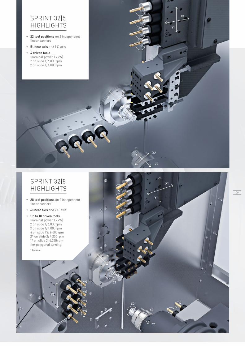
SPRINT 32|5HIGHLIGHTS
+ 22 tool positions on 2 independent linear carriers
+ 5 linear axis and 1 C-axis
+ 4 driven tools (nominal power 1.9 kW) 2 on slide 1; 6,000 rpm 2 on slide 1; 4,000 rpm
SPRINT 32|8HIGHLIGHTS
+ 28 tool positions on 2 independent linear carriers
+ 6 linear axis and 2 C-axis
+ Up to 10 driven tools (nominal power 1.9 kW) 2 on slide 1; 6,000 rpm 2 on slide 1; 4,000 rpm 4 on slide Y2; 6,000 rpm 2* on slide 2; 4,250 rpm 1* on slide 2; 4,250 rpm (for polygonal turning)* Optional
X2
Z2
Z1
Z1
C1
Y2
Z2
X2
C2
C1
Y1
X1
Y1
X1

SPRINT 20|5 / SPRINT 20|8 | SPRINT 32|5 / SPRINT 32|8
SWISSTYPEkit: Changeover between short and long part turning in under 30 minutes.
+ Maximum flexibility due to short and long part turning on one machine
+ Economical production, use bar stock quality as required: + Short turning: – medium quality bars H11 – rest piece length min 70 mm for SPRINT 20 – rest piece length min 81 mm for SPRINT 32 + Long turning: – high quality bars H9 – rest piece length min 171 mm in for SPRINT 20 – rest piece length min 203 mm in for SPRINT 32
+ Vibration-free machining with driven guide bush with spindle synchronisation
+ Easy to convert: Install the guide bush and switch the control system through the menu
+ Extended spindle travel from 60 to 180 mm on SPRINT 20, from 100 to 240 mm on SPRINT 32
SHORT TURNING
MEDICAL | DENTAL IMPLANT
+ ø 6 × 11 mm, titanium alloy
+ 160 seconds per workpiece
+ 11 tools
+ Machining with driven tools
+ 4-axis interpolation turning (X, Y, Z and C)
+ High-speed milling at 6,000 rpm at the counter spindle*
+ Surface finish of 16 µm* Optional
LONG TURNING WITHSWISSTYPEkit*
AUTOMOTIVE | INJECTOR
+ ø 12.2 × 34.5 mm, AISI 303
+ 95 seconds per workpiece
+ 13 tools
+ Machining with SWISSTYPEkit
+ Front machining with 6 tools
+ Milling with Y-axis
+ Chip removal facilitated by high-pressure coolant** Optional
Machine and technology
Applications and parts› Short turning› Long turning with SWISSTYPEkit
Technical data
Control technology
1010

SPRINT 20|5 / SPRINT 20|8 | SPRINT 32|5 / SPRINT 32|8
Expertise in technology – short and long part turning with SWISSTYPEkit.
Screw (medical)
Short turningWorkpiece material Titanium
Bar diameter 4 mm H11
Workpiece dimensions ø 4 × 20 mm
Machining time 66 seconds
HighlightThread whirling at the main spindle
with Direct Drive Technology
Fitting (hydraulics)
Short turningWorkpiece material Steel (95MnPb28)
Bar diameter 30 mm H9
Workpiece dimensions ø 30 × 65 mm
Machining time 160 seconds
Highlight Simultaneous 4-axis machining
Axis (hydraulics)
Long turning with SWISSTYPEkitWorkpiece material Steel (CK45)
Bar diameter 16 mm H9
Workpiece dimensions ø 16 × 95 mm
Machining time 250 seconds
Highlight Deep-hole drilling
Bone screw (medical)
Long turning with SWISSTYPEkitWorkpiece material Titanium
Bar diameter 12 mm H9
Workpiece dimensions ø 12 × 80 mm
Machining time 224 seconds
HighlightThread whirling at the main spindle
with Direct Drive Technology
1111
1
2
3
4
88
711,030
1,82
1
425
1,00
0
1,921
1,992
2,11
8
415
1,030
1,21
0
1,200
653
607
1,05
7
355
1,12
3
638
917
470
9
120
Extraction chip bin
Machine and technology
Applications and parts
Technical data› Layout plans
Control technology
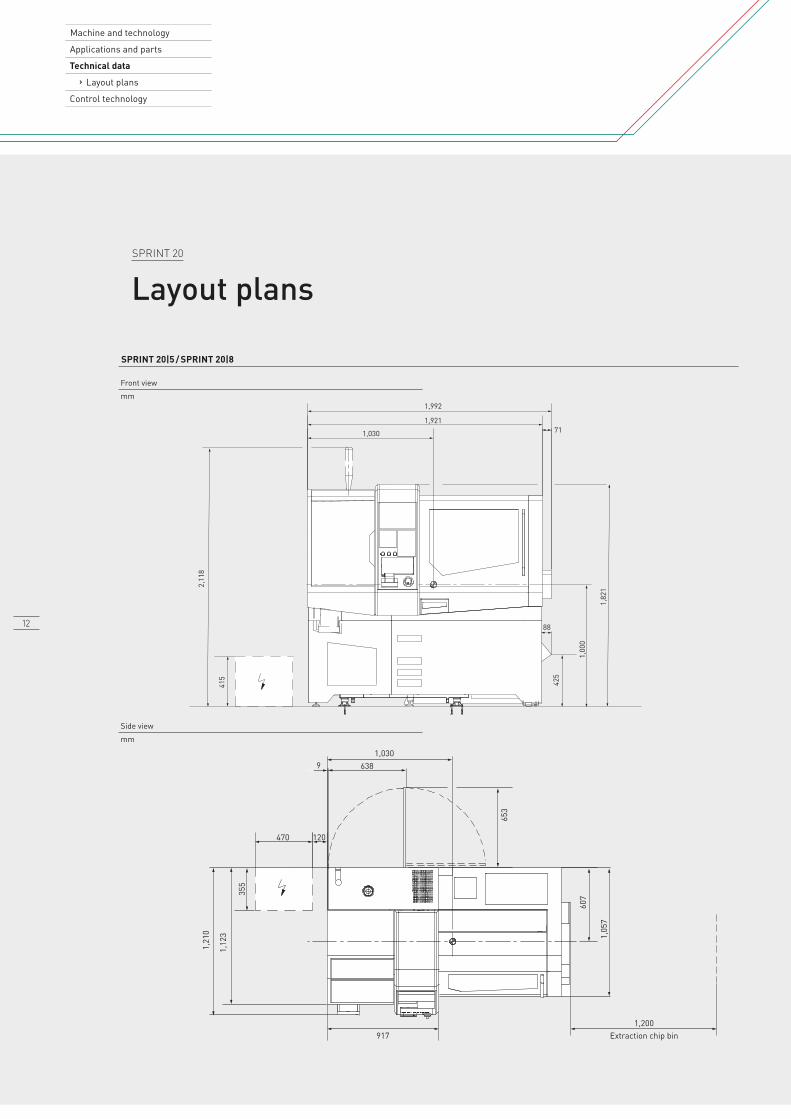
SPRINT 20
Layout plans
SPRINT 20|5 / SPRINT 20|8
Front viewmm
Side viewmm
12

2,38
4
475
373
1,10
02,
087
1,151
76
1,44
71,
355
380
1,151
691
730
1,28
0
510 300
67710
1,390Extraction chip bin
SPRINT 32
Layout plans
SPRINT 32|5 / SPRINT 32|8
Front viewmm
Side viewmm
13

Torque(Nm)
Power(kW)
Spee
d(r
pm)
272421181512
3
96
3
1
2
23.6 Nm
14 Nm
S2 (30 min)
3.7 kW
2.2 kW
S2 (30 min)
S1
S1
0
1,00
0
2,00
0
3,00
0
4,00
0
5,00
0
6,00
0
7,00
0
8,00
0
9,00
0
10,0
00
Torque(Nm)
Power(kW)
Spee
d(r
pm)
272421181512
3
96
3
1
2
7 Nm
4.8Nm
S2 (30 min)
2.2 kW
1.5 kW
S2 (30 min)
S1
S1
0
1,00
0
2,00
0
3,00
0
4,00
0
5,00
0
6,00
0
7,00
0
8,00
0
9,00
0
10,0
00
SPRINT 20|5 / SPRINT 20|8 | SPRINT 32|5 / SPRINT 32|8
Main drives with Direct Drive technology for maximum performance.
SPRINT 20|5 / 20|8Main spindle
SPRINT 20|5 / 20|8Counter spindle
SPRINT 32|5 / 32|8Main spindle
SPRINT 32|5 / 32|8Counter spindle
Maximum speed rpm 10,000 10,000 8,500 8,500
Power (S2 30 min / S1) kW 3.7 / 2.2 2.2 / 1.5 *7.5 / 5.5 3.7 / 2.2
Torque (S2 30 min / S1) Nm 23.6 / 14 7 / 4.8 *51.9 / 40.4 23.6 / 14
Maximum cutting diameter Nm 20 20 32 32
High-performance turning (95MnPb28 | 20 / 32 mm bar diameter)Material removal rate cm3 / min 130 85 220 130
Depth of cut mm 2.5 1.5 3.5 2.5
Feed mm / rev 0.3 0.3 0.35 0.3
Spindle speed rpm 3,200 3,200 2,000 2,000
Material removal rate cm3 / min 115 80 115 115
Depth of cut mm 3.5 3 4.5 3.5
Feed mm / rev 0.2 0.15 0.2 0.2
Spindle speed rpm 3,200 3,200 2,000 2,000
High-performance boring (9SMnPb28 | 20 / 32 mm bar diameter)Solid drill mm 12 10 15 12
Feed mm / rev 0.2 0.2 0.25 0.2
Threads (9SMnPb28 | 20 / 32 mm bar diameter)Thread size mm M10 × 1.5 M8 × 1.25 M14 × 1.25 M10 × 1.5
* S2 15 min / S1
SPRINT 20|5 / SPRINT 20|8
Main Spindle10,000 rpm
Counter Spindle10,000 rpm
Machine and technology
Applications and parts
Technical data› Spindles
Control technology
14

Torque(Nm)
Power(kW)
Spee
d(r
pm)
6
5
4
3
2
1
1.75
1.25
1.5
0.25
1
0.75
0.5
2 Nm
1.3 Nm
S3 (40%)
1.3 kW
0.8 kW
S2 (40 %)
S1
S1
0
1,00
0
2,00
0
3,00
0
4,00
0
5,00
0
6,00
0
Torque(Nm)
Power(kW)
Spee
d(r
pm)
3.5
3
2.5
2
1.5
0.5
1
1.75
1.25
1.5
0.25
1
0.75
0.5
3 NmS1
S11 kW
3.5 Nm 1.9 kWS3 (40 %) S3 (40 %)
0
1,00
0
2,00
0
3,00
0
4,00
0
5,00
0
6,00
0
Torque(Nm)
Power(kW)
Spee
d(r
pm)
6
5
4
3
2
1
1.75
1.25
1.5
0.25
1
0.75
0.5
3.5 Nm
3 Nm
S3 (40%)
1.3 kW
0.8 kW
S2 (40 %)
S1 S1
0
1,00
0
2,00
0
3,00
0
3,45
0
Torque(Nm)
Power(kW)
Spee
d(r
pm)
5
4
3
2
1
1.75
1.25
1.5
0.25
1
0.75
0.5
5.25 Nm
4.5 Nm
S3 (40%)
1.9 kW
1 kW
S3 (40 %)
S1
S1
0
500
1,00
0
1,50
0
2,00
0
2,50
0
3,00
0
3,50
0
4,00
0
Torque(Nm)
Power(kW)
Spee
d(r
pm)
50
40
30
10
20
6
5
1
4
3
2
51.9 Nm
40.4 Nm
S2 (15 min)
7.5 kW
5.5 kW
S2 (15 min)
S1 S1
0
1,00
0
2,00
0
3,00
0
4,00
0
5,00
0
6,00
0
7,00
0
8,00
08,
500
Torque(Nm)
Power(kW)
Spee
d(r
pm)
20
15
10
5
3.5
2.5
3
0.5
2
1.5
1
23.6 Nm
14.4 Nm
S2 (30 min)3.7 kW
2.2 kW
S2 (30 min)
S1 S1
0
1,00
0
2,00
0
3,00
0
4,00
0
5,00
0
6,00
0
7,00
0
8,00
08,
500
SPRINT 32|5 / SPRINT 32|8
SPRINT 20|5 / SPRINT 20|8
SPRINT 32|5 / SPRINT 32|8
Driven tool stations on slide 16,000 rpm
Driven tool stations on slide 16,000 rpm
Main Spindle8,500 rpm
Driven tool stations on slide 14,000 rpm
Driven tool stations on slide 13,450 rpm
Counter Spindle8,500 rpm
15

Machine and technology
Applications and parts
Technical data› Technical data› Options
Control technology
SPRINT 20|5 / SPRINT 20|8 | SPRINT 32|5 / SPRINT 32|8
Technical data
SPRINT 20|5 SPRINT 20|8 SPRINT 32|5 SPRINT 32|8Machine conceptNumber of linear axes + C-axes 5 + 1 6 + 2 5 + 1 6 + 2Number of spindles 2 2 2 2Number of channels 2 2 2 2Main spindleMaximum bar capacity mm 20 20 32 32Speed rpm 10,000 10,000 8,500 8,500
Power (S2 30 min / S1) kW 3.7 / 2.2 3.7 / 2.27.5 / 5.5
S2 15 min / S17.5 / 5.5
S2 15 min / S1
Torque (S2 30 min / S1) Nm 23.6 / 14 23.6 / 1451.9 / 40.4
S2 15 min / S151.9 / 40.4
S2 15 min / S1Counter spindleMaximum bar capacity mm 20 20 32 32C-axis (0.001 °) Optional Standard – StandardSpeed rpm 10,000 10,000 8,500 8,500Power (S2 30 min / S1) kW 2.2 / 1.5 2.2 / 1.5 3.7 / 2.2 3.7 / 2.2Torque (S2 30 min / S1) Nm 7.0 / 4.8 7.0 / 4.8 23.6 / 14 23.6 / 14Working area / travelsZ1 travel (spindle travel) mm 60 / 180** 60 / 180** 100 / 240** 100 / 240**Tool carrier 1: X1 / Y1 travel mm 50 / 325 50 / 325 70 / 405 70 / 405Counter spindle: X2 / Z2 travel mm 220 / 170 220 / 170 300 / 200 300 / 200Tool carrier 2: Y2 travel mm – 85 – 135Rapid traverse speed on linear axes X1, Z1, X2, Z2 / Y1, Y2
m / min 32 / 32 32 / 32 40 / 30 40 / 30
Acceleration in linear axes m / s² 5 5 5 5Tool holder on slide 1Fixed turning tools 6 6 6 6Tools for front machining / back-working 6 / 3 3 / 3 4 / 4 4 / 4Driven tools 2 + 2 2 + 2 2 + 2 2 + 2Maximum speed rpm 6,000 6,000 6,000 6,000Power (S3 40 % / S1) kW 1.3 / 0.8 1.3 / 0.8 1.9 / 1 1.9 / 1
Maximum torque (S3 40 % / S1) Nm 2 / 1.3 2 / 1.3 3.5 / 3 3.5 / 3
Maximum speed rpm 3,450 3,450 4,000 4,000Power (S3 40 % / S1) kW 1.3 / 0.8 1.3 / 0.8 1.9 / 1 1.9 / 1Maximum torque (S3 40 % / S1) Nm 3.5 / 3 3.5 / 3 5.25 / 4.5 5.25 / 4.5Tool holder on slide Y2 On station for back working On station for back workingFixed / driven tools for back-working 4 / 0 (2 / 2)*** 3 / 2 + 2 4 / 0 4 / 4 (5 / 4)*Maximum speed rpm 6,000 6,000 – 6,000Power (S3 40 % / S1) kW 1.2 / 1 1.3 / 0.8 – 1.9 / 1Maximum torque (S3 40 % / S1) Nm 2.5 / 2 2 / 1.3 – 3.5 / 3
Maximum speed rpm – 3,450 – –Power (S3 40 % / S1) kW – 1.3 / 0.8 – –Maximum torque (S3 40 % / S1 Nm – 3.5 / 3 – –Tool holder on slide 2
Fixed / driven tools for back-working – – –2 / 0 (0 / 2)*
(0 /1 for polygons)*Maximum speed rpm – – – 4,250Power (S3 40 % / S1) kW – – – 1.9 / 1Maximum torque (S3 40 % / S1) Nm – – – 3.5 / 3
16

SPRINT 20|5 / SPRINT 20|8 | SPRINT 32|5 / SPRINT 32|8
Options
SPRINT 20|5 SPRINT 20|8 SPRINT 32|5 SPRINT 32|8MachineFootprint m² 1.96 1.96 2.8 2.8Machine height mm 1.821 1.821 2.085 2.085Machine weight (including coolant tank) kg 2,300 2,500 3,450 3,550Control systemDMG MORI SLIMline Control with 10.4″ monitor FANUC 32i FANUC 32i FANUC 32i FANUC 32i* Optional, ** Optional with SWISSTYPEkit, *** SPRINT 20|5 C-axis on the counter spindle when you choose driven tools for back-working,– not available
SPRINT 20|5 SPRINT 20|8 SPRINT 32|5 SPRINT 32|8
Tools2 driven tools on station for back working, including C-axis for the counter spindle
* – – –
2 driven tools besides the counter spindle – – – *
Driven angle head drilling and milling attachment for slide 1 * * * *
Driven angle head drilling and milling attachment for slide Y2 – * – *
Bar machiningSWISSTYPEkit: Short turning to long turning conversion kit, including driven guide bush
* * * *
Bar loading magazine * * * *Workpiece unload through counter spindle: maximum workpiece length 600 mm
* * * *
Workpiece unload: through counter spindle maximum workpiece length 100 mm
** ** ** **
Coolant and chip disposalSlat band conveyor with a chip ejection height of: 600 mm (compatible with workpiece unload through counter spindle)
* * * *
12-bar internal coolant supply system, unit for oil and emulsion
* * * *
Conversion kit for operating the machine with emulsion instead of oil
* * * *
Conveyor belt for finished workpieces * * ** **
Oil mist extraction system * * * *
Control systemTool wear monitoring system * * * *
Sister tool management system * * * *
DMG MORI Netservice ** ** ** **
DMG MORI Messenger * * * *
DMG MORI Service Agent * * * *
MiscellaneousSignal lamp 4-colour * * * *Machine adaptation for increased ambient temperatures of up to 50 °C (tropical package)
* * * *
* Optional, – Not available, ** Standard in base machine
17

Machine and technology
Applications and parts
Technical data
Control technology
18

DMG MORI SLIMline CONTROL
Control panel with 10.4″ colour display and FANUC 32i.
+ DMG MORI SMARTkey for user access
+ Dual Check Safety System for monitoring machine movements
+ Enhanced stock removal cycles for turning, external threading, boring, rigid tapping and hobbing
+ DMG MORI cycles for machine monitoring: feed thrust reduction, position monitoring and axial stopping
+ Programming of complex cycles using the external CAD-CAM system ESPRIT*
+ USB interface
+ Tool Monitoring System* with graphical tool load display
+ 2 MB NC RAM*Optional
FANUC NC FOROPTIMIZED PRODUCTION
+ 2 control channels, up to 6 linear axes and up to 2 C-axes
+ Multi-channel screen for displaying both control channels
LOAD MONITOR ANDSISTER TOOLS
+ Load monitor software as option analyzes current absorption to show tools wear
+ Tailor made pages for production control, according to Industry 4.0 requirements
19

DMGMORI.COMDMG MORI LifeCycle Services
Customer First – Our service promise!“We have good news for you: Our service and spare parts prices have been completely revised. With our service commitments, we want to meet your high demands with the highest service quality.”
Please contact us – your sales and service team is at your disposal!Available for you around the clock:
service-hotline.dmgmori.com
* All information and price advantages for Customer First are available at: customer-first.dmgmori.com
Best Price Guarantee for Original Spare Parts. Should you get a spare part offered by us at least 20 % cheaper elsewhere, we will refund the price difference up to 100 % *.
Up to 50 % lower service costs. New Flat Call-Out Rate – without travel expenses or any additional costs!
Spindle service at best prices. The highest level of competence from the manufacturer at new and attractive prices – DMG MORI spindle service!
Our protective shield for your productivity. Reduced operating costs, highest machine availability and maximum precision – DMG MORI Service Plus!
Top quality at fair prices. It's a promise!
Subj
ect t
o m
odifi
catio
n. T
echn
ical
upd
ate
righ
ts re
serv
ed. T
he m
achi
nes
depi
cted
her
e m
ay in
clud
e so
me
optio
ns, e
quip
men
t and
CN
C al
tern
ativ
es.
P201
8038
5_07
18_E
N