CMOS FABRICATION - India’s Premier Educational … very thin layer of gate oxide using Chemical...
42
CMOS FABRICATION n – WELL PROCESS
Transcript of CMOS FABRICATION - India’s Premier Educational … very thin layer of gate oxide using Chemical...

CMOS FABRICATION
n – WELL PROCESS

Step 1: Si Substrate
Start with p- type substrate
p substrate

Step 2: Oxidation
Exposing to high-purity oxygen and hydrogen at approx. 1000oC in oxidation furnace
p substrate
SiO2

Step 3: Photoresist Coating
Photoresist is a light-sensitive organic polymerSoftens when exposed to light
p substrate
SiO2
Photoresist

Step 4: Masking
Expose photoresist through n-well mask
p s u b s t r a t e
S iO 2
P h o t o r e s is t
Uv rays
n-well mask
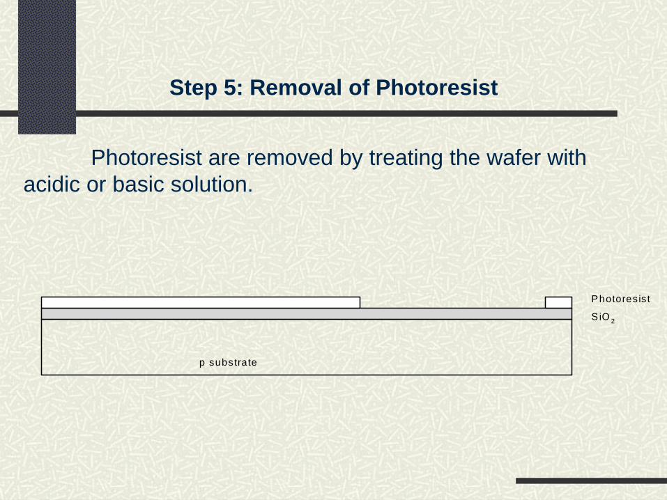
Step 5: Removal of Photoresist
Photoresist are removed by treating the wafer with acidic or basic solution.
p substrate
S iO 2
Photoresist

Step 6: Acid Etching
SiO2 is selectively removed from areas of wafer that are not covered by photoresist by using hydrofluoric acid.
p substrate
SiO2
Photoresist

Step 7: Removal of Photoresist
Strip off the remaining photoresist
p substrate
SiO2

Step 8: Formation of n-well
n-well is formed with diffusion or ion implantation
n well
SiO2

Step 9: Removal of SiO2
Strip off the remaining oxide using HF
p substraten well
wafer with n-well

Step 10: Polysilicon deposition
Deposit very thin layer of gate oxide using Chemical Vapor Deposition (CVD) process
Thin gate oxidePolysilicon
p substraten well
p substrate
Thin gate oxidePolysilicon
n well
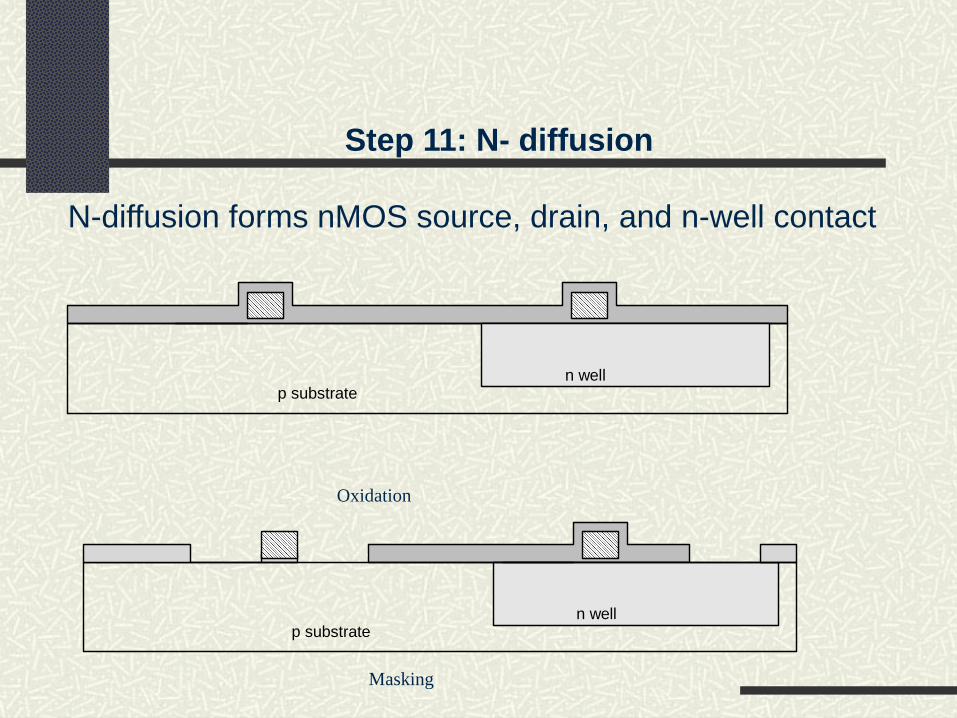
Step 11: N- diffusion
N-diffusion forms nMOS source, drain, and n-well contact
p substraten well
p substraten well
Oxidation
Masking

Step 11: N- diffusion
n wellp substrate
n+n+ n+
n wellp substrate
n+n+ n+
Diffusion
Dopants were diffused or ion implantated
Strip off oxide
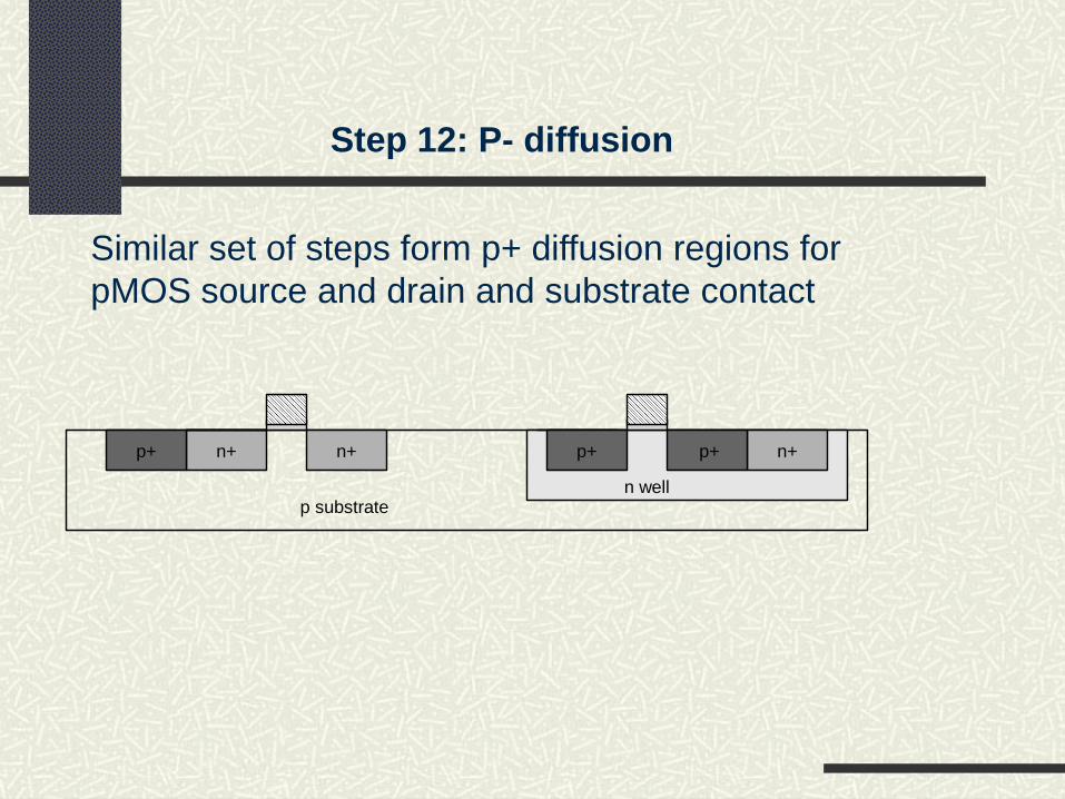
Step 12: P- diffusion
Similar set of steps form p+ diffusion regions for pMOS source and drain and substrate contact
p substraten well
n+n+ n+p+p+p+

Step 13: Contact cuts
The devices are to be wired together
Cover chip with thick field oxide
Etch oxide where contact cuts are needed
p substrate
Thick field oxide
n well
n+n+ n+p+p+p+

Step 14: Metallization
Sputter on aluminum over whole wafer
Pattern to remove excess metal, leaving wires
p substrate
Metal
Thick field oxide
n well
n+n+ n+p+p+p+

p-well CMOS process
The fabrication of p-well cmos process is similar to n-well process except that p-wells acts as substrate for the n-devices within the parent n-substrate

Advantages of n-well process
n-well CMOS are superior to p-well because of
lower substrate bias effects on transistor thresholdvoltage
lower parasitic capacitances associated with sourceand drain region
Latch-up problems can be considerably reduced byusing a low resistivity epitaxial p-type substrate
However n-well process degrades the performanceof poorly performing p-type transistor

Twin -Tub Process

LOGIC GATES

CMOS INVERTER

NAND Gate

NOR Gate

STICK DIAGRAM
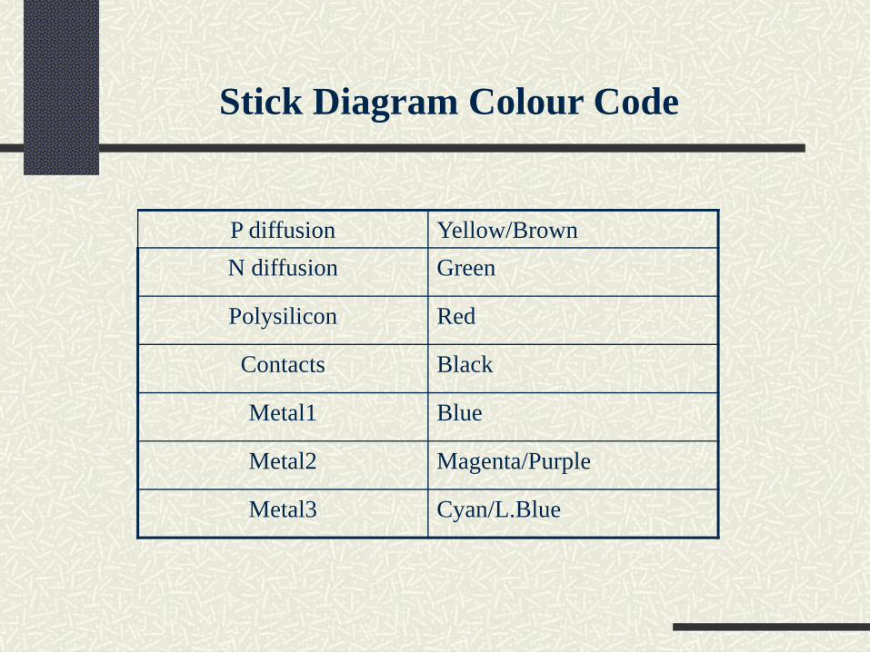
Stick Diagram Colour Code
P diffusion Yellow/Brown N diffusion Green
Polysilicon Red
Contacts Black
Metal1 Blue
Metal2 Magenta/Purple
Metal3 Cyan/L.Blue

Component Colour Use
metal 1 Power and signal wires
metal 2 Power wires
polysilicon Signal wires and transistor gates
n-diffusion Signal wires,source and drain of transistors
p-diffusion Signal wires,source and drain of transistors
contact Signal connection
via Connection between metals

NMOS transistor
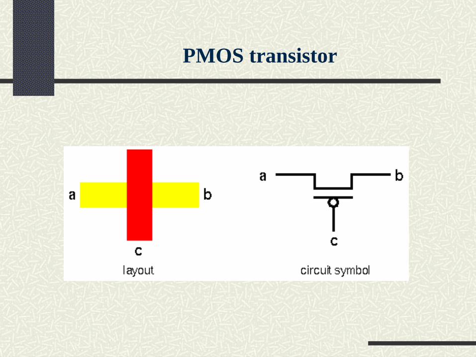
PMOS transistor

INVERTER- STICK DIAGRAM
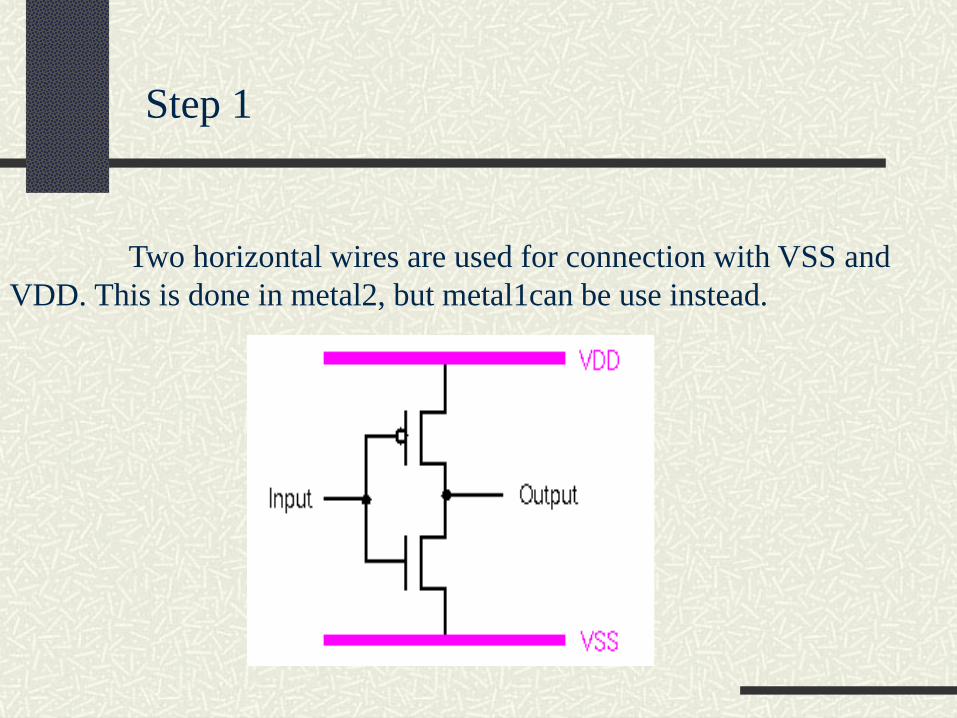
Two horizontal wires are used for connection with VSS and VDD. This is done in metal2, but metal1can be use instead.
Step 1

Step 2
Two vertical wires (pdiff and ndiff) are used to represent the p-transistor (yellow) and n-transistor (green).

Step 3
The gates of the transistors are joined with a polysilicon wire, and connected to the input.
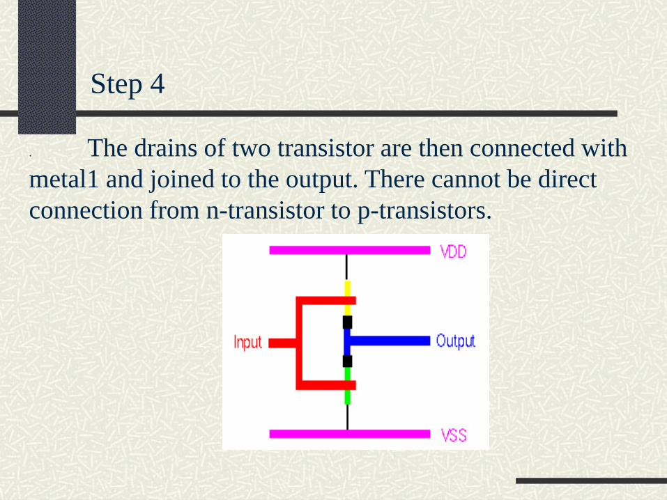
Step 4
. The drains of two transistor are then connected with metal1 and joined to the output. There cannot be direct connection from n-transistor to p-transistors.

Step 5
The sources of the transistors are next connected to VSS and VDD with metal1. Notice that vias are used, not contacts

metal1 is used instead of metal2 to connect VSS and VDD supply
Alternative inverter

NAND Gate

NOR Gate

Layout Design Rules
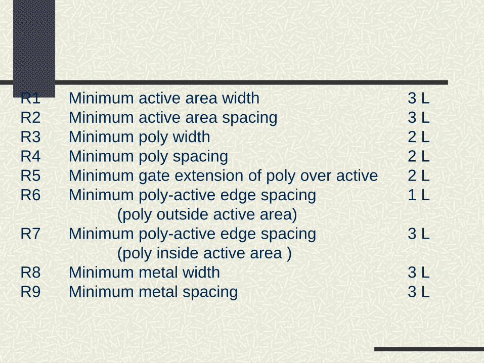
R1 Minimum active area width 3 LR2 Minimum active area spacing 3 LR3 Minimum poly width 2 LR4 Minimum poly spacing 2 LR5 Minimum gate extension of poly over active 2 LR6 Minimum poly-active edge spacing 1 L
(poly outside active area)R7 Minimum poly-active edge spacing 3 L
(poly inside active area )R8 Minimum metal width 3 LR9 Minimum metal spacing 3 L

R10 Poly contact size 2 LR11 Minimum poly contact spacing 2 LR12 Minimum poly contact to poly edge spacing 1 LR13 Minimum poly contact to metal edge spacing 1 LR14 Minimum poly contact to active edge spacing 3 LR15 Active contact size 2 LR16 Minimum active contact spacing 2 L
(on the same active region)R17 Minimum active contact to active edge spacing 1 LR18 Minimum active contact to metal edge spacing 1 LR19 Minimum active contact to poly edge spacing 3 LR20 Minimum active contact spacing 6 L
(on different active regions)

OTHER CMOS LOGIC

![[TA1-D] Hybrid Oxide Thin Films](https://static.fdocuments.net/doc/165x107/615ab33bad71057f9352b7b6/ta1-d-hybrid-oxide-thin-films.jpg)