CME6 0 0 A EVALUATI ON DATA 型式データ - TDK
36
CME600A EVALUATION DATA 型式データ TDK-Lambda CA926-53-01
Transcript of CME6 0 0 A EVALUATI ON DATA 型式データ - TDK
CME600A
EVALUATION DATA
型式データ
TDK-Lambda CA926-53-01
CME600A
INDEX
1. 測定方法 Evaluation Method PAGE1-1. 測定回路 Circuit used for determination
測定回路1 Circuit 1 used for determination .............................................................................................................3静特性 Steady state data通電ドリフト特性 Warm up voltage drift characteristics出力保持時間特性 Hold up time characteristics出力立ち上がり特性 Output rise characteristics出力立ち下がり特性 Output fall characteristics過電流保護特性 Over current protection (OCP) characteristics過電圧保護特性 Over voltage protection (OVP) characteristics入力電圧瞬停特性 Response to brown out characteristics各種信号 Various signal
測定回路2 Circuit 2 used for determination ..............................................................................................................................3過渡応答(負荷急変)特性 Dynamic load response characteristics
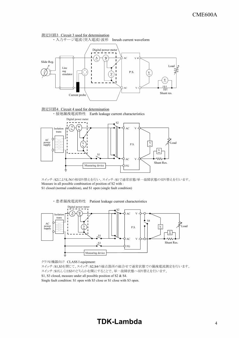
測定回路3 Circuit 3 used for determination .....................................................................................................................4入力サージ電流(突入電流)波形 Inrush current waveform
測定回路4 Circuit 4 used for determination .....................................................................................................................4接地漏洩電流特性 Earth leakage current characteristics患者漏洩電流特性 Patient leakage current characteristics
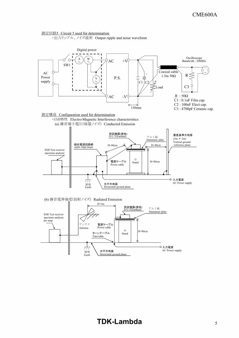
測定回路5 Circuit 5 used for determination .....................................................................................................................5出力リップル、ノイズ波形 Output ripple and noise waveform
測定構成 Configuration used for determination ........................................................................................................................5EMI特性 Electro-Magnetic Interference characteristics(a) 雑音端子電圧(帰還ノイズ) Conducted Emission(b) 雑音電界強度(放射ノイズ) Radiated Emission
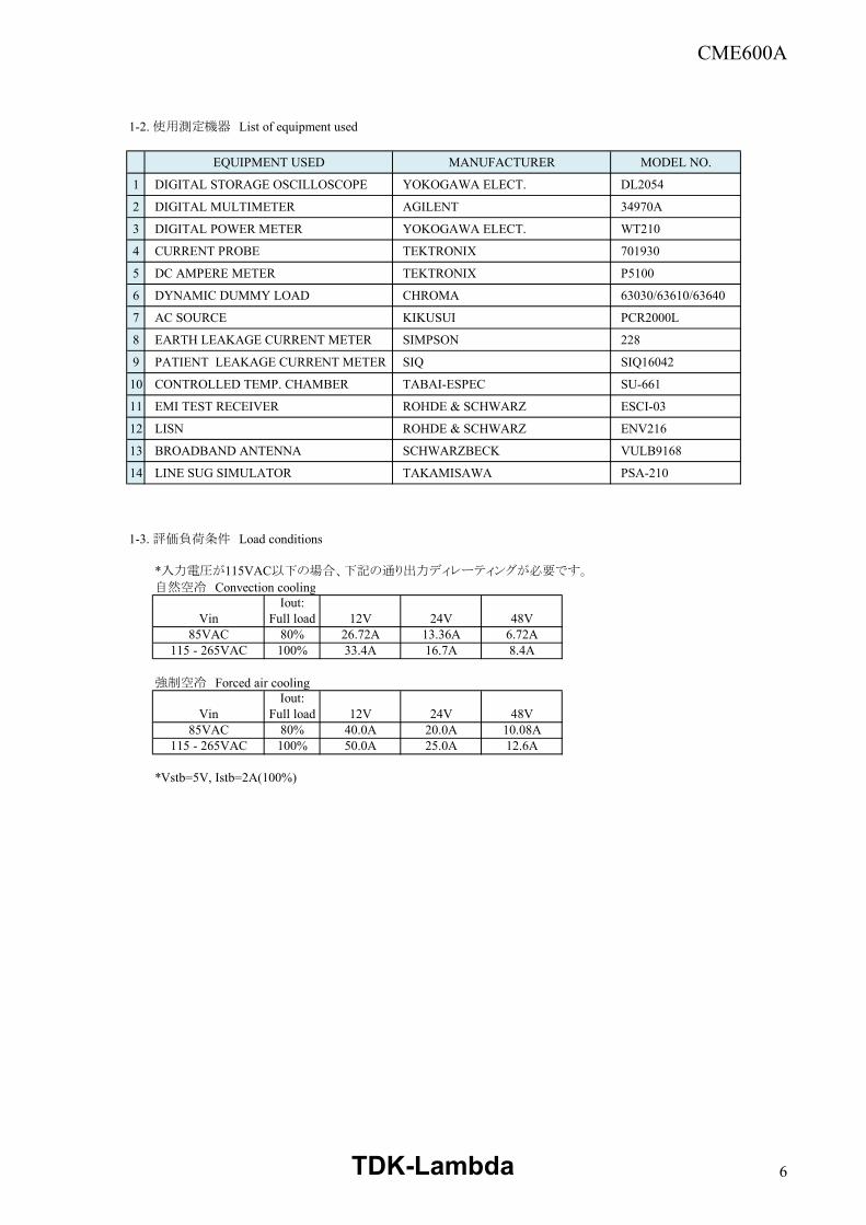
1-2. 使用測定機器 List of equipment used ....................................................................................................................................6
1-3. 評価負荷条件 Load conditions ....................................................................................................................................6
TDK-Lambda 1
CME600A
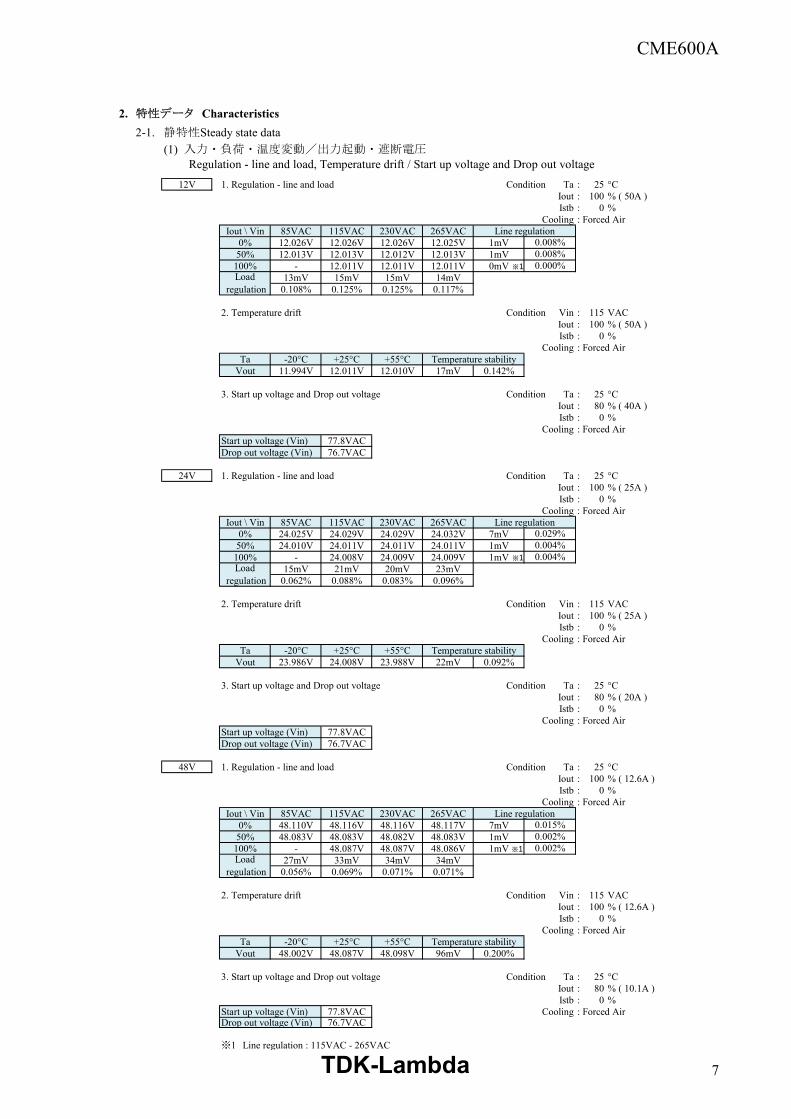
2. 特性データ Characteristics PAGE2-1. 静特性 Steady state data
(1) 入力・負荷・温度変動/出力起動・遮断電圧
Regulation - line and load, Temperature drift / Start up voltage and Drop out voltage ............................................................................................................7(2) 効率・力率対出力電流 Efficiency and Power factor vs. Output current .......................................................................................................................................8(3) 入力電力対出力電流 Input power vs. Output current ..........................................................................................................9(4) 入力電流対出力電流 Input current vs. Output current ..........................................................................................................10(5) リモートOFF時入力電力対出力電流 Input power vs. Output current @ Remote OFF ................................................................................................11
2-2. 通電ドリフト特性 Warm up voltage drift characteristics ............................................................................................................122-3. 保持時間特性 Hold up time characteristics ..................................................................................................................................122-4. 出力電圧立ち上がり特性 Output rise characteristics .............................................................................................................................................................132-5. 出力電圧立ち下がり特性 Output fall characteristics ................................................................................................................................................142-6. 各種信号 Various signal ................................................................................................................................................152-7. 過電流保護特性 Over current protection (OCP) characteristics ............................................................................................................162-8. 過電圧保護特性 Over voltage protection (OVP) characteristics ...................................................................................162-9. 過渡応答(負荷急変)特性 Dynamic load response characteristics ..........................................................................................172-10. 入力電圧瞬停特性 Response to brown out characteristics ..........................................................................................182-11. 入力サージ電流(突入電流)波形 Inrush current waveform .........................................................................................................................................192-12. 高調波成分 Input current harmonics ...............................................................................................................................................................................................202-13. 漏洩電流特性 Leakage current characteristics ............................................................................................................21~222-14. 出力リップル、ノイズ波形 Output ripple and noise waveform ....................................................................................................232-15. EMI特性 Electro-Magnetic Interference characteristics .........................................................................................................................................................24~35
使用記号 'Terminology used定義 Definition
Vin ......... 入力電圧 Input voltageVout ......... 出力電圧 Output voltageIin ......... 入力電流 Input currentIout ......... 出力電流 Output currentTa ......... 周囲温度 Ambient temperatureVstb ......... スタンバイ電圧 Output voltage of standbyIstb ......... スタンバイ電流 Output current of standby
※ 当社測定条件における結果であり、参考値としてお考え願います。
Test results are reference data based on our measurement condition.
TDK-Lambda 2
CME600A
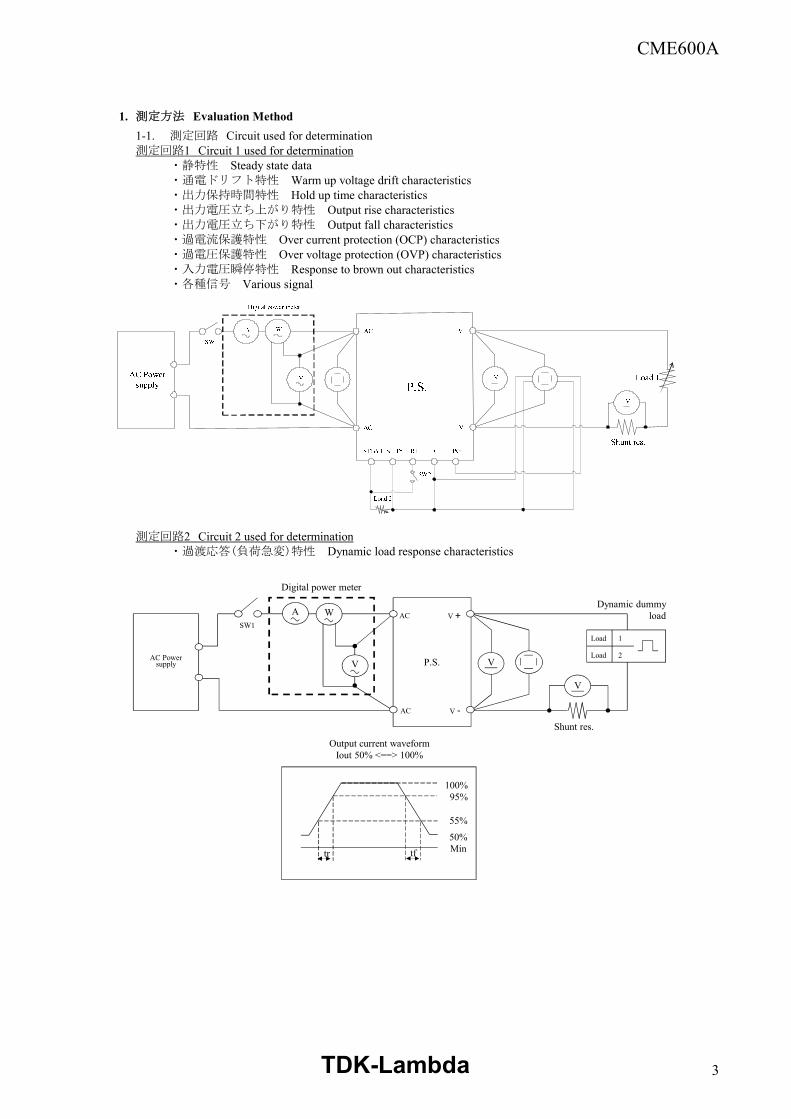
1. 測定方法 Evaluation Method1-1. 測定回路 Circuit used for determination測定回路1 Circuit 1 used for determination
・静特性 Steady state data・通電ドリフト特性 Warm up voltage drift characteristics・出力保持時間特性 Hold up time characteristics・出力電圧立ち上がり特性 Output rise characteristics・出力電圧立ち下がり特性 Output fall characteristics・過電流保護特性 Over current protection (OCP) characteristics・過電圧保護特性 Over voltage protection (OVP) characteristics・入力電圧瞬停特性 Response to brown out characteristics・各種信号 Various signal
測定回路2 Circuit 2 used for determination・過渡応答(負荷急変)特性 Dynamic load response characteristics
P.S.AC Powersupply
tr tf
100%95%
Output current waveformIout 50% <==> 100%
AC
AC
Load 1
Load 2
V
V
V +
V -Shunt res.
Dynamic dummyload
SW1
55%
A W
V
Digital power meter
50%Min
TDK-Lambda 3
CME600A
測定回路3 Circuit 3 used for determination・入力サージ電流(突入電流)波形 Inrush current waveform
測定回路4 Circuit 4 used for determination・接地漏洩電流特性 Earth leakage current characteristics
スイッチ:S2によりL/Nの相切り替えを行い、スイッチ:S1で通常状態/単一故障状態の切り替えを行います。
・患者漏洩電流特性 Patient leakage current characteristics
クラスI 機器向け CLASS I equipment:スイッチ:S1,S3を閉じて、スイッチ:S2,S4の接点箇所の組合せで通常状態での漏洩電流測定を行います。
スイッチ:S1もしくはS3のどちらかを開にすることで、単一故障状態へ切り替えを行います。
S1, S3 closed, measure under all possible position of S2 & S4. Single fault condition: S1 open with S3 close or S1 close with S3 open.
Measure in all possible combination of position of S2 with :S1 closed (normal condition), and S1 open (single fault condition)
A W
V
AC
AC
P.S.
V
V
V +
V -
Shunt res.
Load
Digital power meter
Current probe
Slide Reg.
Line sugsimulator
Measuring device
S1
AC power supply
Isolation trans
Digital power meter
A W
V
AC
AC
FGShunt Res.
Load
V -
V +
V
V
P.S.
S2
Measuring device
S1
AC power supply
Isolation trans
Digital power meter
A W
V
AC
AC
FG
V -
V -
Shunt Res.
LoadV
V
P.S.
S2
S3
S4
TDK-Lambda 4
CME600A
測定回路5 Circuit 5 used for determination・出力リップル、ノイズ波形 Output ripple and noise waveform
測定構成 Configuration used for determination・EMI特性 Electro-Magnetic Interference characteristics (a) 雑音端子電圧(帰還ノイズ) Conducted Emission
(b) 雑音電界強度(放射ノイズ) Radiated Emission
P.S.AC
Powersupply
AC
AC
+V
-V
SW1
A W
V
Digital power
Load
R
R : 50ΩC1 : 0.1uF Film cap.C2 : 100uF Elect cap.C3 : 4700pF Ceramic cap.
Coaxial cable1.5m 50Ω
OscilloscopeBandwith : 20MHz
150mm
+
C1 C2C3
アルミ板Aluminum plate
垂直基準大地面
(2m × 2m)Vertical groundreference plane D=40cm疑似電源回路網
AMN 50Ω/50uH
供試機器(接地)D.U.T(Earthed)
D=80cm
H=80cm台
Stand
入力電源AC Power supply
電源ケーブルPower cable
接地Earth
水平大地面Horizontal ground plane
EMI Test receiverspectrum analyzer
供試機器(接地)D.U.T(Earthed) アルミ板
Aluminum plate
アンテナ
Antenna
EMI Test receiver spectrum analyzerpre amp.
水平大地面Horizontal ground plane
D=3m
H=80cm
入力電源AC Power supply
ターンテーブルTurn table
電源ケーブルPower cable
接地Earth
台Stand
TDK-Lambda 5
CME600A
1-2. 使用測定機器 List of equipment used
EQUIPMENT USED MANUFACTURER MODEL NO.
1 DIGITAL STORAGE OSCILLOSCOPE YOKOGAWA ELECT. DL2054
2 DIGITAL MULTIMETER AGILENT 34970A
3 DIGITAL POWER METER YOKOGAWA ELECT. WT210
4 CURRENT PROBE TEKTRONIX 701930
5 DC AMPERE METER TEKTRONIX P5100
6 DYNAMIC DUMMY LOAD CHROMA 63030/63610/63640
7 AC SOURCE KIKUSUI PCR2000L
8 EARTH LEAKAGE CURRENT METER SIMPSON 228
9 PATIENT LEAKAGE CURRENT METER SIQ SIQ16042
10 CONTROLLED TEMP. CHAMBER TABAI-ESPEC SU-661
11 EMI TEST RECEIVER ROHDE & SCHWARZ ESCI-03
12 LISN ROHDE & SCHWARZ ENV216
13 BROADBAND ANTENNA SCHWARZBECK VULB9168
14 LINE SUG SIMULATOR TAKAMISAWA PSA-210
1-3. 評価負荷条件 Load conditions
*入力電圧が115VAC以下の場合、下記の通り出力ディレーティングが必要です。
自然空冷 Convection coolingIout:
Full load80%100%
強制空冷 Forced air coolingIout:
Full load80%100%
*Vstb=5V, Istb=2A(100%)
8.4A6.72A
Vin 24V12V 48V85VAC
115 - 265VAC26.72A33.4A
13.36A16.7A
115 - 265VAC 50.0A 25.0A 12.6A
Vin 12V 24V 48V85VAC 40.0A 20.0A 10.08A
TDK-Lambda 6
CME600A
2. 特性データ Characteristics2-1. 静特性Steady state data
(1) 入力・負荷・温度変動/出力起動・遮断電圧Regulation - line and load, Temperature drift / Start up voltage and Drop out voltage
12V 1. Regulation - line and load Condition Ta : 25 °CIout : 100 % ( 50A )Istb : 0 %
Cooling : Forced AirIout \ Vin 85VAC 115VAC 230VAC 265VAC Line regulation
0% 12.026V 12.026V 12.026V 12.025V 1mV50% 12.013V 12.013V 12.012V 12.013V 1mV
100% - 12.011V 12.011V 12.011V 0mV13mV 15mV 15mV 14mV
0.108% 0.125% 0.125% 0.117%
2. Temperature drift Condition Vin : 115 VACIout : 100 % ( 50A )Istb : 0 %
Cooling : Forced AirTa -20°C +25°C +55°C Temperature stability
Vout 11.994V 12.011V 12.010V 17mV 0.142%
3. Start up voltage and Drop out voltage Condition Ta : 25 °CIout : 80 % ( 40A )Istb : 0 %
Cooling : Forced AirStart up voltage (Vin) 77.8VACDrop out voltage (Vin) 76.7VAC
24V 1. Regulation - line and load Condition Ta : 25 °CIout : 100 % ( 25A )Istb : 0 %
Cooling : Forced AirIout \ Vin 85VAC 115VAC 230VAC 265VAC Line regulation
0% 24.025V 24.029V 24.029V 24.032V 7mV50% 24.010V 24.011V 24.011V 24.011V 1mV
100% - 24.008V 24.009V 24.009V 1mV15mV 21mV 20mV 23mV
0.062% 0.088% 0.083% 0.096%
2. Temperature drift Condition Vin : 115 VACIout : 100 % ( 25A )Istb : 0 %
Cooling : Forced AirTa -20°C +25°C +55°C Temperature stability
Vout 23.986V 24.008V 23.988V 22mV 0.092%
3. Start up voltage and Drop out voltage Condition Ta : 25 °CIout : 80 % ( 20A )Istb : 0 %
Cooling : Forced AirStart up voltage (Vin) 77.8VACDrop out voltage (Vin) 76.7VAC
48V 1. Regulation - line and load Condition Ta : 25 °CIout : 100 % ( 12.6A )Istb : 0 %
Cooling : Forced AirIout \ Vin 85VAC 115VAC 230VAC 265VAC Line regulation
0% 48.110V 48.116V 48.116V 48.117V 7mV50% 48.083V 48.083V 48.082V 48.083V 1mV
100% - 48.087V 48.087V 48.086V 1mV27mV 33mV 34mV 34mV
0.056% 0.069% 0.071% 0.071%
2. Temperature drift Condition Vin : 115 VACIout : 100 % ( 12.6A )Istb : 0 %
Cooling : Forced AirTa -20°C +25°C +55°C Temperature stability
Vout 48.002V 48.087V 48.098V 96mV 0.200%
3. Start up voltage and Drop out voltage Condition Ta : 25 °CIout : 80 % ( 10.1A )Istb : 0 %
Start up voltage (Vin) 77.8VAC Cooling : Forced AirDrop out voltage (Vin) 76.7VAC
※1 Line regulation : 115VAC - 265VAC
0.008%0.008%0.000%
Load regulation
0.029%0.004%0.004%
Load regulation
0.015%0.002%0.002%
Load regulation
※1
※1
※1
TDK-Lambda 7
CME600A
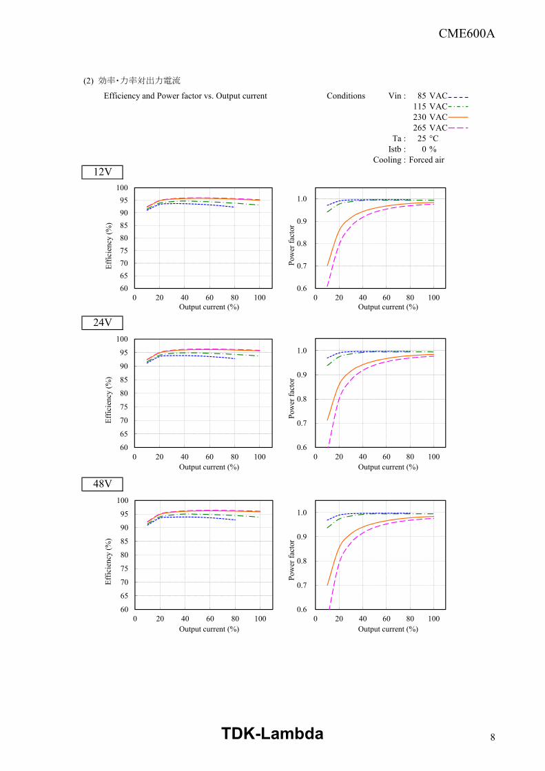
(2) 効率・力率対出力電流
Efficiency and Power factor vs. Output current Conditions Vin : 85 VAC115 VAC230 VAC265 VAC
Ta : 25 °CIstb : 0 %
Cooling : Forced air12V
24V
48V
6065707580859095
100
0 20 40 60 80 100
Effic
ienc
y (%
)
Output current (%)
0.6
0.7
0.8
0.9
1.0
0 20 40 60 80 100Po
wer
fact
or
Output current (%)
60
65
70
75
80
85
90
95
100
0 20 40 60 80 100
Effic
ienc
y (%
)
Output current (%)
0.6
0.7
0.8
0.9
1.0
0 20 40 60 80 100
Pow
er fa
ctor
Output current (%)
60
65
70
75
80
85
90
95
100
0 20 40 60 80 100
Effic
ienc
y (%
)
Output current (%)
0.6
0.7
0.8
0.9
1.0
0 20 40 60 80 100
Pow
er fa
ctor
Output current (%)
TDK-Lambda 8
CME600A
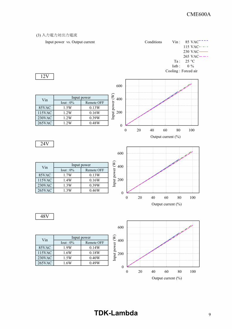
(3) 入力電力対出力電流
Input power vs. Output current Conditions Vin : 85 VAC115 VAC230 VAC265 VAC
Ta : 25 °CIstb : 0 %
Cooling : Forced air12V
Input powerIout : 0% Remote OFF
85VAC 1.5W 0.13W115VAC 1.2W 0.16W230VAC 1.2W 0.39W265VAC 1.2W 0.48W
24V
Input powerIout : 0% Remote OFF
85VAC 1.7W 0.13W115VAC 1.4W 0.16W230VAC 1.3W 0.39W265VAC 1.3W 0.46W
48V
Input powerIout : 0% Remote OFF
85VAC 1.9W 0.14W115VAC 1.6W 0.18W230VAC 1.5W 0.40W265VAC 1.6W 0.49W
Vin
Vin
Vin
0
200
400
600
0 20 40 60 80 100
Inpu
t pow
er (W
)
Output current (%)
0
200
400
600
0 20 40 60 80 100
Inpu
t pow
er (W
)
Output current (%)
0
200
400
600
0 20 40 60 80 100
Inpu
t pow
er (W
)
Output current (%)
TDK-Lambda 9
CME600A
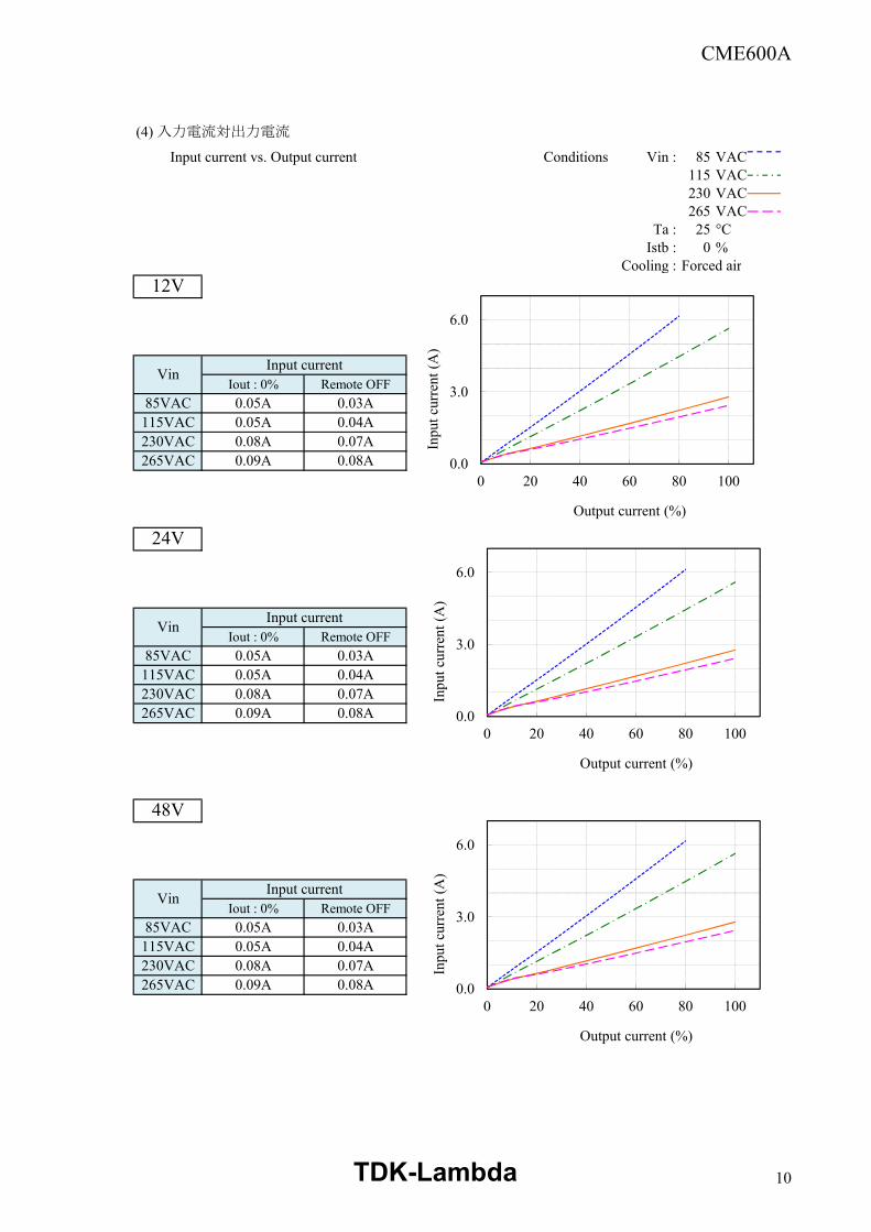
(4) 入力電流対出力電流
Input current vs. Output current Conditions Vin : 85 VAC115 VAC230 VAC265 VAC
Ta : 25 °CIstb : 0 %
Cooling : Forced air12V
Input currentIout : 0% Remote OFF
85VAC 0.05A 0.03A115VAC 0.05A 0.04A230VAC 0.08A 0.07A265VAC 0.09A 0.08A
24V
Input currentIout : 0% Remote OFF
85VAC 0.05A 0.03A115VAC 0.05A 0.04A230VAC 0.08A 0.07A265VAC 0.09A 0.08A
48V
Input currentIout : 0% Remote OFF
85VAC 0.05A 0.03A115VAC 0.05A 0.04A230VAC 0.08A 0.07A265VAC 0.09A 0.08A
Vin
Vin
Vin
0.0
3.0
6.0
0 20 40 60 80 100
Inpu
t cur
rent
(A)
Output current (%)
0.0
3.0
6.0
0 20 40 60 80 100
Inpu
t cur
rent
(A)
Output current (%)
0.0
3.0
6.0
0 20 40 60 80 100
Inpu
t cur
rent
(A)
Output current (%)
TDK-Lambda 10
CME600A
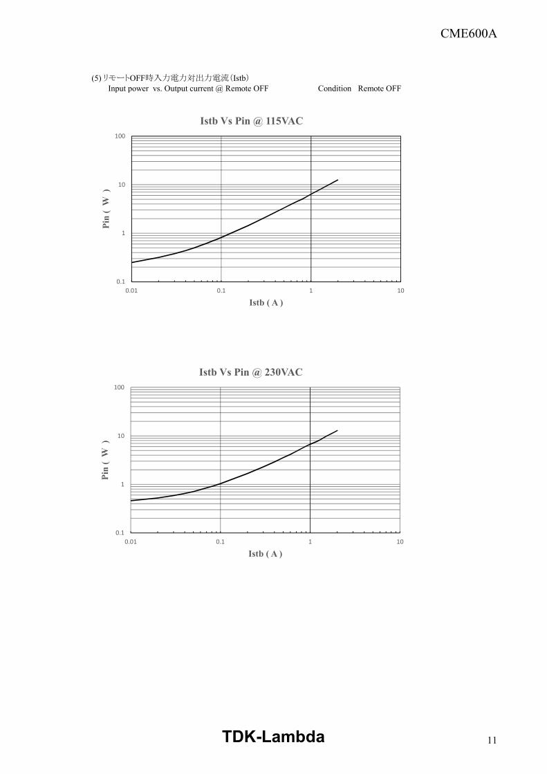
(5) リモートOFF時入力電力対出力電流(Istb) Input power vs. Output current @ Remote OFF Condition : Remote OFF
0.1
1
10
100
0.01 0.1 1 10
Pin
( W
)
Istb ( A )
Istb Vs Pin @ 115VAC
0.1
1
10
100
0.01 0.1 1 10
Pin
( W
)
Istb ( A )
Istb Vs Pin @ 230VAC
TDK-Lambda 11
CME600A
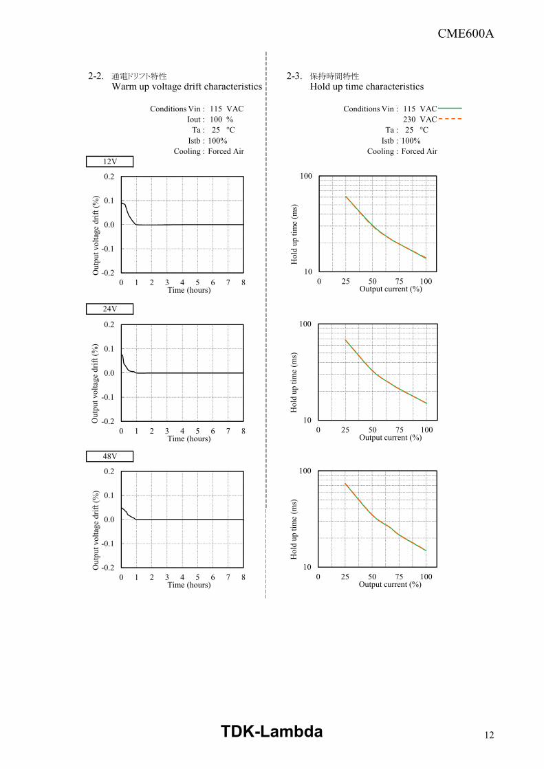
2-2. 通電ドリフト特性 2-3. 保持時間特性
Warm up voltage drift characteristics Hold up time characteristics
Conditions Vin : 115 VAC Conditions Vin : 115 VACIout : 100 % 230 VAC
Ta : 25 °C Ta : 25 °CIstb :’100% Istb :’100%
Cooling : Forced Air Cooling : Forced Air12V
24V
48V
-0.2
-0.1
0.0
0.1
0.2
0 1 2 3 4 5 6 7 8
Out
put v
olta
ge d
rift (
%)
Time (hours)
10
100
0 25 50 75 100H
old
up ti
me
(ms)
Output current (%)
-0.2
-0.1
0.0
0.1
0.2
0 1 2 3 4 5 6 7 8
Out
put v
olta
ge d
rift (
%)
Time (hours)
10
100
0 25 50 75 100
Hol
d up
tim
e (m
s)
Output current (%)
-0.2
-0.1
0.0
0.1
0.2
0 1 2 3 4 5 6 7 8
Out
put v
olta
ge d
rift (
%)
Time (hours)
10
100
0 25 50 75 100
Hol
d up
tim
e (m
s)
Output current (%)
TDK-Lambda 12
CME600A
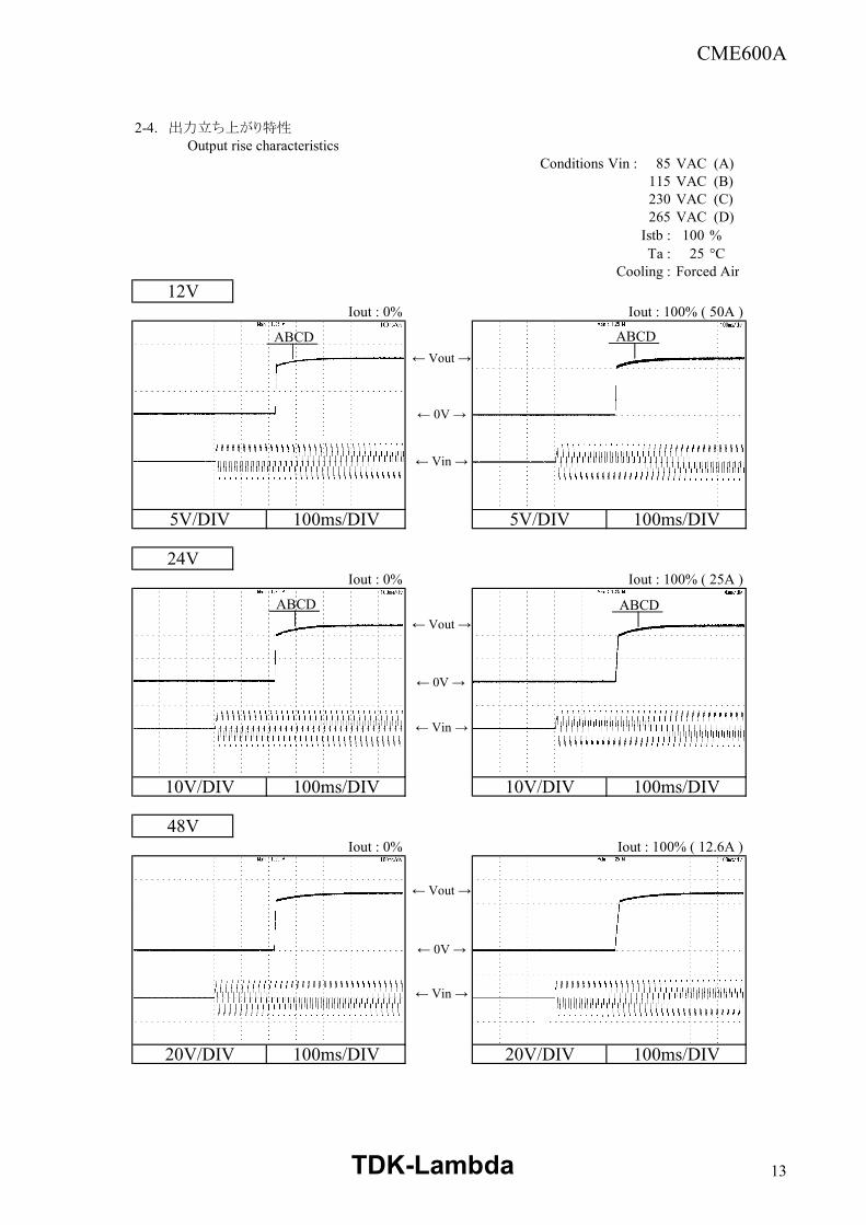
2-4. 出力立ち上がり特性 Output rise characteristics
Conditions Vin : 85 VAC (A)115 VAC (B)230 VAC (C)265 VAC (D)
Istb : 100 %Ta : 25 °C
Cooling : Forced Air
12VIout : 0% Iout : 100% ( 50A )
5V/DIV 100ms/DIV 5V/DIV 100ms/DIV
24VIout : 0% Iout : 100% ( 25A )
10V/DIV 100ms/DIV 10V/DIV 100ms/DIV
48VIout : 0% Iout : 100% ( 12.6A )
20V/DIV 100ms/DIV 20V/DIV 100ms/DIV
← Vin →
← 0V →
← Vout →
← Vin →
← 0V →
← Vout →
← Vin →
← 0V →
← Vout →
ABCDABCD
ABCDABCD
ABCDABCD
TDK-Lambda 13
CME600A
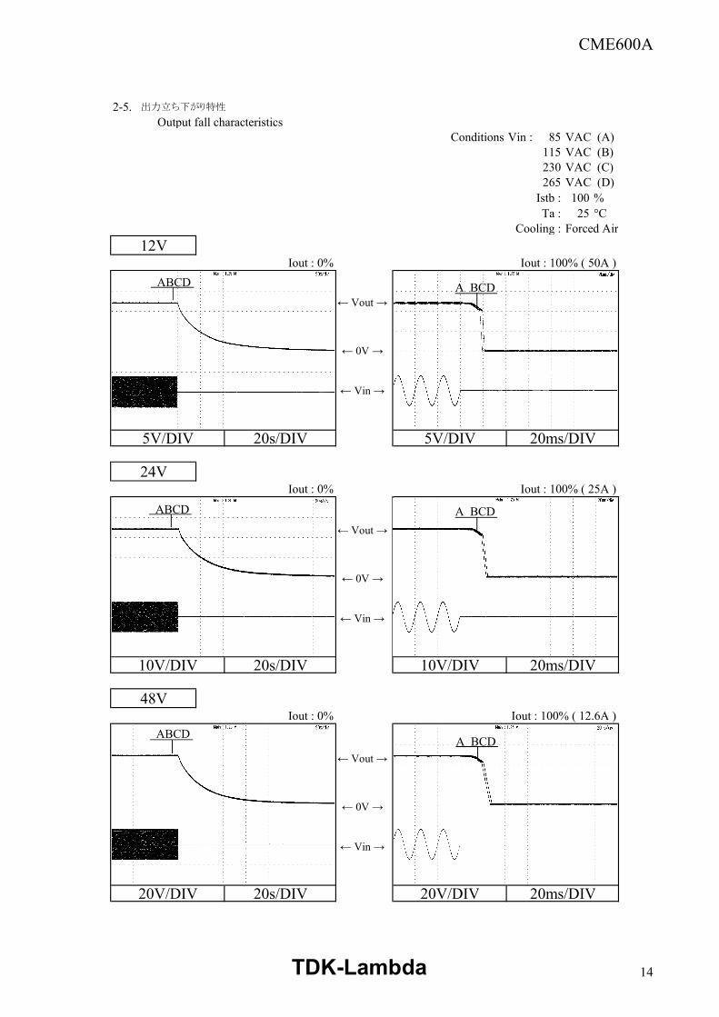
2-5. 出力立ち下がり特性 Output fall characteristics
Conditions Vin : 85 VAC (A)115 VAC (B)230 VAC (C)265 VAC (D)
Istb : 100 %Ta : 25 °C
Cooling : Forced Air
12VIout : 0% Iout : 100% ( 50A )
5V/DIV 20s/DIV 5V/DIV 20ms/DIV
24VIout : 0% Iout : 100% ( 25A )
10V/DIV 20s/DIV 10V/DIV 20ms/DIV
48VIout : 0% Iout : 100% ( 12.6A )
20V/DIV 20s/DIV 20V/DIV 20ms/DIV
← Vin →
← 0V →
← Vout →
← Vin →
← 0V →
← Vout →
← Vin →
← 0V →
← Vout →
A BCDABCD
A BCDABCD
ABCDA BCD
TDK-Lambda 14
CME600A
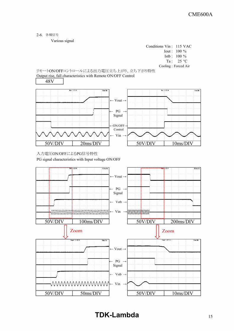
2-6. 各種信号
Various signalConditions Vin : 115 VAC
Iout : 100 %Istb : 100 %Ta : 25 °C
Cooling : Forced AirリモートON/OFFコントロールによる出力電圧立ち上がり、立ち下がり特性Output rise, fall characteristics with Remote ON/OFF Control
48V
50V/DIV 20ms/DIV 50V/DIV 10ms/DIV
入力電圧ON/OFFによるPG信号特性
PG signal characteristics with Input voltage ON/OFF
50V/DIV 100ms/DIV 50V/DIV 200ms/DIV
50V/DIV 50ms/DIV 50V/DIV 10ms/DIV
← PG →Signal
← Vout →
← Vin →
←ON/OFF→Control
← PG →Signal
← Vout →
← Vin →
← Vstb →
← PG →Signal
← Vout →
← Vin →
← Vstb →
c
Zoom
c
Zoom
TDK-Lambda 15
CME600A
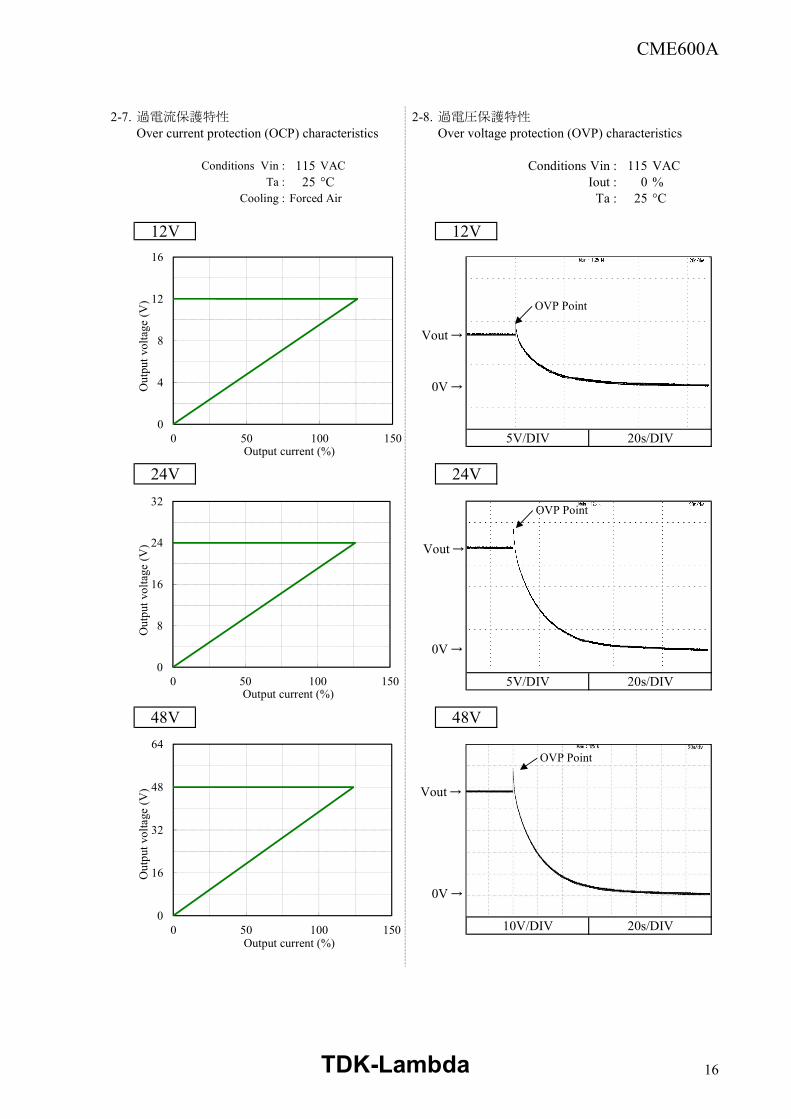
2-7. 過電流保護特性 2-8. 過電圧保護特性Over current protection (OCP) characteristics Over voltage protection (OVP) characteristics
Conditions Vin : 115 VAC Conditions Vin : 115 VACTa : 25 °C Iout : 0 %
Cooling : Forced Air Ta : 25 °C
12V 12V
5V/DIV 20s/DIV
24V 24V
5V/DIV 20s/DIV
48V 48V
10V/DIV 20s/DIV
0
4
8
12
16
0 50 100 150
Out
put v
olta
ge (
V)
Output current (%)
0
16
32
48
64
0 50 100 150
Out
put v
olta
ge (
V)
Output current (%)
0V→
Vout→
0V→
Vout→
0V→
Vout→
0
8
16
24
32
0 50 100 150
Out
put v
olta
ge (
V)
Output current (%)
OVP Point
OVP Point
OVP Point
TDK-Lambda 16
CME600A
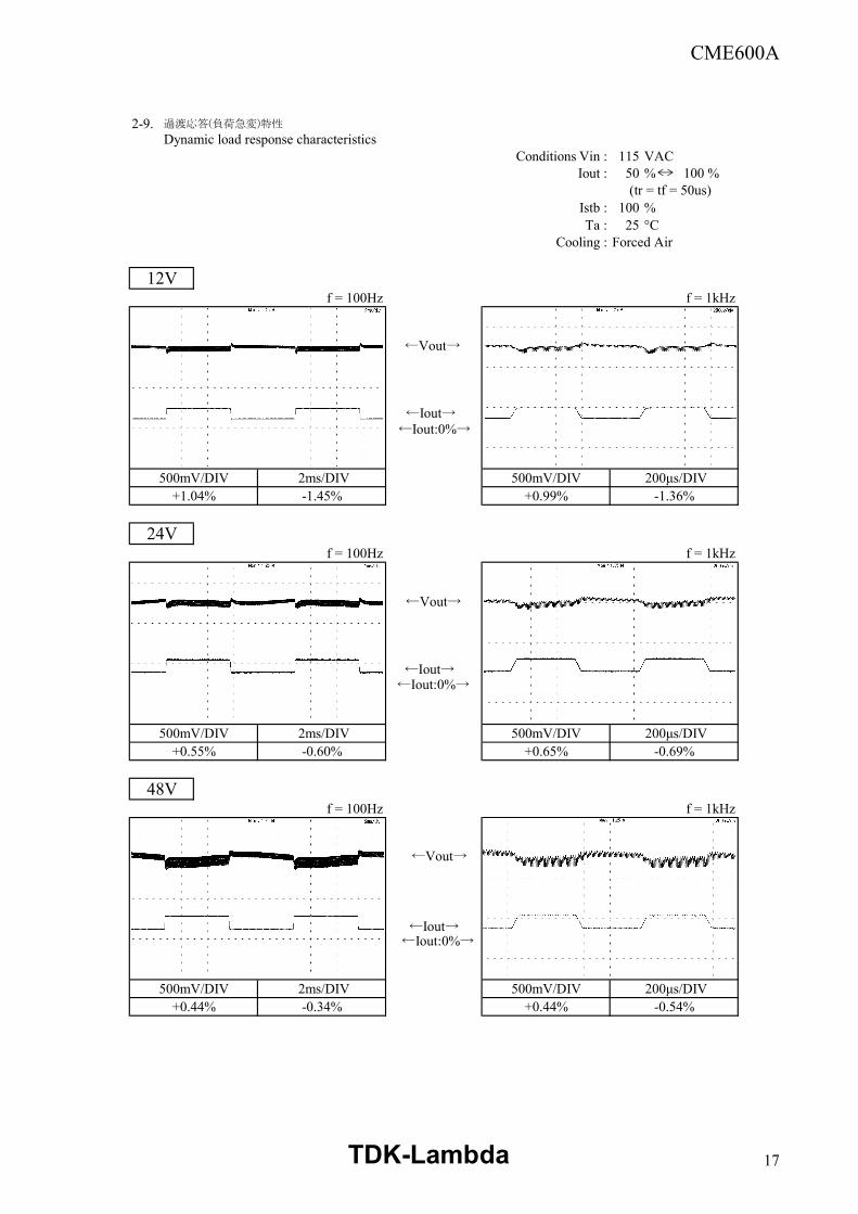
2-9. 過渡応答(負荷急変)特性
Dynamic load response characteristicsConditions Vin : 115 VAC
Iout : 50 % 100 % (tr = tf = 50us)
Istb : 100 %Ta : 25 °C
Cooling : Forced Air
12Vf = 100Hz f = 1kHz
500mV/DIV 2ms/DIV 500mV/DIV 200μs/DIV+1.04% -1.45% +0.99% -1.36%
24Vf = 100Hz f = 1kHz
500mV/DIV 2ms/DIV 500mV/DIV 200μs/DIV+0.55% -0.60% +0.65% -0.69%
48Vf = 100Hz f = 1kHz
500mV/DIV 2ms/DIV 500mV/DIV 200μs/DIV+0.44% -0.34% +0.44% -0.54%
←Iout:0%→
←Vout→
←Iout→
←Vout→
←Iout:0%→
←Vout→
←Iout→
←Iout→←Iout:0%→
TDK-Lambda 17
CME600A
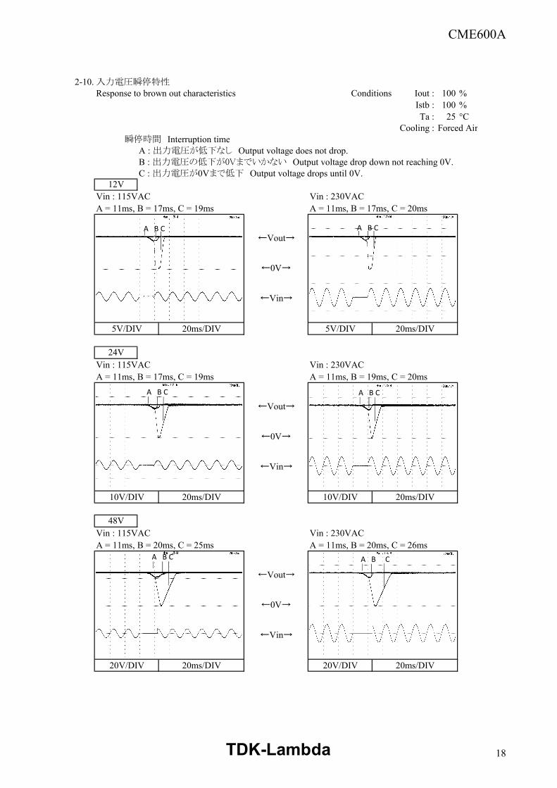
2-10.入力電圧瞬停特性Response to brown out characteristics Conditions Iout : 100 %
Istb : 100 % Ta : 25 °C
Cooling : Forced Air 瞬停時間 Interruption time
A : 出力電圧が低下なし Output voltage does not drop.B : 出力電圧の低下が0Vまでいかない Output voltage drop down not reaching 0V.C : 出力電圧が0Vまで低下 Output voltage drops until 0V.
Vin : 115VAC Vin : 230VACA = 11ms, B = 17ms, C = 19ms A = 11ms, B = 17ms, C = 20ms
5V/DIV 20ms/DIV 5V/DIV 20ms/DIV
Vin : 115VAC Vin : 230VACA = 11ms, B = 17ms, C = 19ms A = 11ms, B = 19ms, C = 20ms
10V/DIV 20ms/DIV 10V/DIV 20ms/DIV
Vin : 115VAC Vin : 230VACA = 11ms, B = 20ms, C = 25ms A = 11ms, B = 20ms, C = 26ms
20V/DIV 20ms/DIV 20V/DIV 20ms/DIV
12V
24V
48V
A B C
←0V→
←Vin→
←Vout→
←0V→
←Vin→
←Vout→
←0V→
←Vin→
←Vout→
A B C
A B C A B C
A B C A B C
TDK-Lambda 18
CME600A
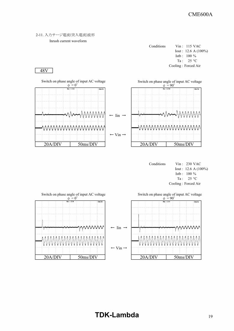
2-11. 入力サージ電流(突入電流)波形
Inrush current waveformConditions Vin : 115 VAC
Iout : 12.6 A (100%)Istb : 100 %Ta : 25 °C
Cooling : Forced Air48V
20A/DIV 50ms/DIV 20A/DIV 50ms/DIV
Conditions Vin : 230 VACIout : 12.6 A (100%)Istb : 100 %Ta : 25 °C
Cooling : Forced Air
20A/DIV 50ms/DIV 20A/DIV 50ms/DIV
Switch on phase angle of input AC voltageφ = 0°
Switch on phase angle of input AC voltageφ = 90°
Switch on phase angle of input AC voltageφ = 0°
Switch on phase angle of input AC voltageφ = 90°
← Iin →
← Vin →
← Iin →
← Vin →
TDK-Lambda 19
CME600A
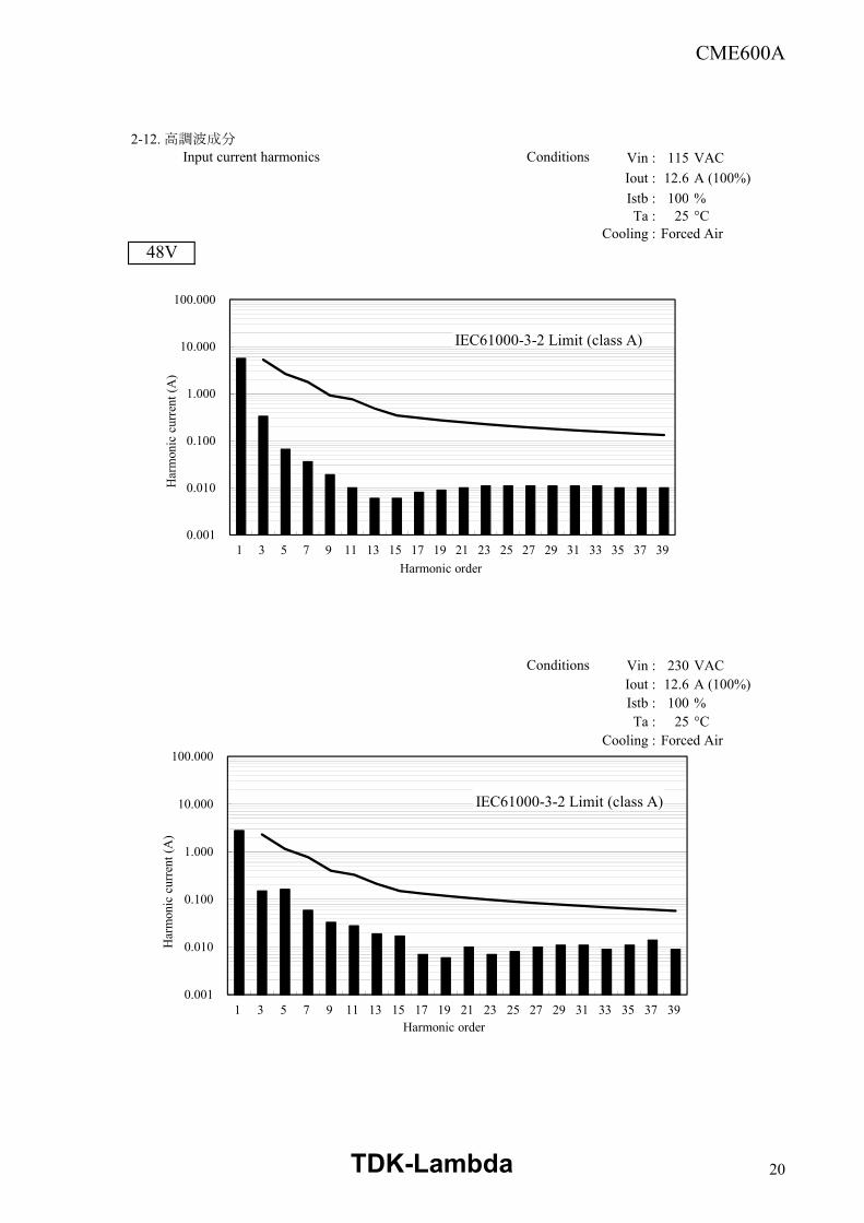
2-12. 高調波成分 Input current harmonics Conditions Vin : 115 VAC
Iout : 12.6 A (100%)Istb : 100 %Ta : 25 °C
Cooling : Forced Air48V
Conditions Vin : 230 VACIout : 12.6 A (100%)Istb : 100 %Ta : 25 °C
Cooling : Forced Air
0.001
0.010
0.100
1.000
10.000
100.000
1 3 5 7 9 11 13 15 17 19 21 23 25 27 29 31 33 35 37 39
Har
mon
ic c
urre
nt (A
)
Harmonic order
0.001
0.010
0.100
1.000
10.000
100.000
1 3 5 7 9 11 13 15 17 19 21 23 25 27 29 31 33 35 37 39
Har
mon
ic c
urre
nt (A
)
Harmonic order
IEC61000-3-2 Limit (class A)
IEC61000-3-2 Limit (class A)
TDK-Lambda 20
CME600A
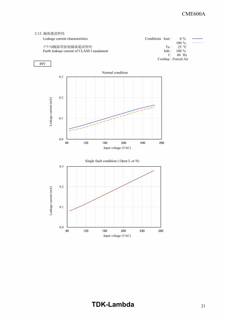
2-13. 漏洩電流特性
Leakage current characteristics Conditions Iout : 0 %100 %
クラスI機器用接地漏洩電流特性 Ta : 25 °CEarth leakage current of CLASS I equipment Istb : 100 %
f : 60 HzCooling : Forced Air
48V
Normal condition
Single fault condition ( Open L or N)
0.0
0.1
0.2
0.3
80 120 160 200 240 280
Leak
age
curre
nt (m
A)
Input voltage (VAC)
0.0
0.1
0.2
0.3
80 120 160 200 240 280
Leak
age
curre
nt (m
A)
Input voltage (VAC)
TDK-Lambda 21
CME600A
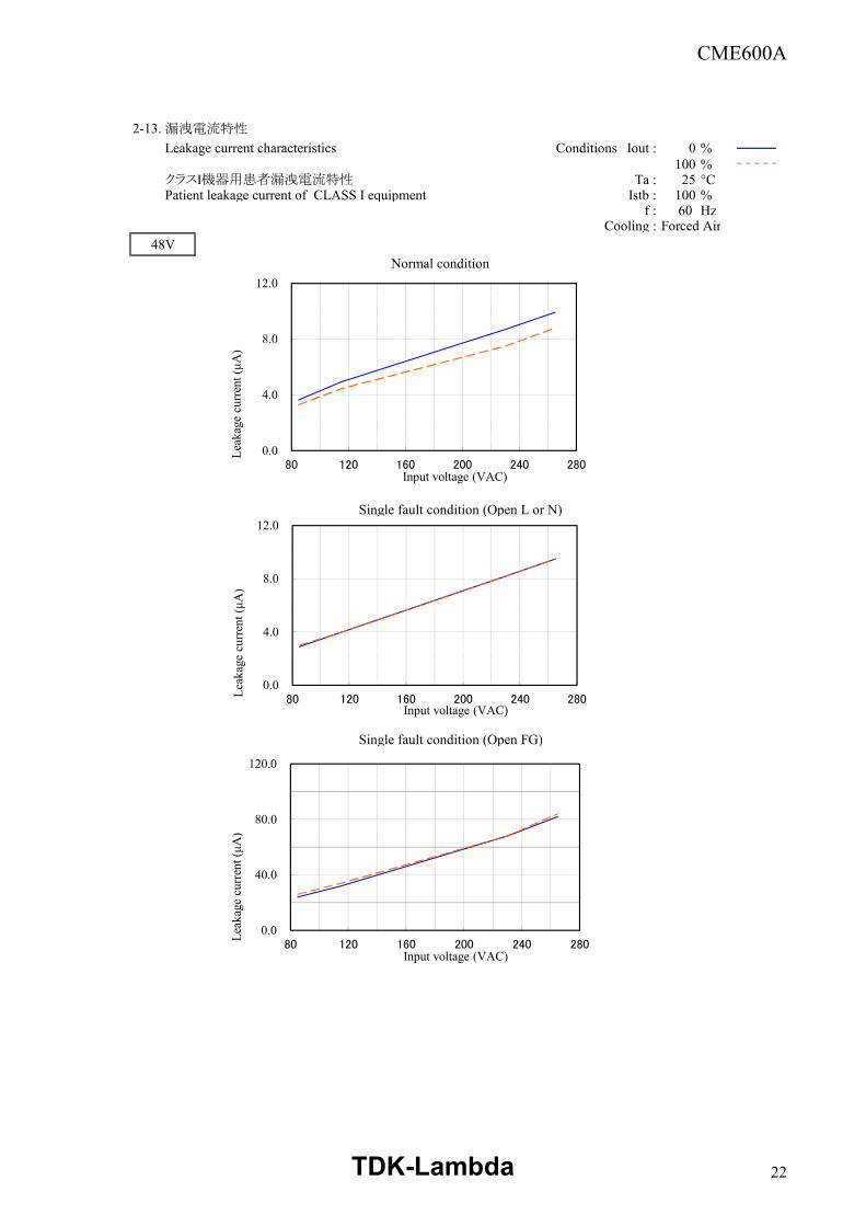
2-13. 漏洩電流特性
Leakage current characteristics Conditions Iout : 0 %100 %
クラスI機器用患者漏洩電流特性 Ta : 25 °CPatient leakage current of CLASS I equipment Istb : 100 %
f : 60 HzCooling : Forced Air
48VNormal condition
Single fault condition (Open L or N)
Single fault condition (Open FG)
0.0
4.0
8.0
12.0
80 120 160 200 240 280
Leak
age
curre
nt (μ
A)
Input voltage (VAC)
0.0
4.0
8.0
12.0
80 120 160 200 240 280Leak
age
curre
nt (μ
A)
Input voltage (VAC)
0.0
40.0
80.0
120.0
80 120 160 200 240 280
Leak
age
curre
nt (μ
A)
Input voltage (VAC)
TDK-Lambda 22
CME600A
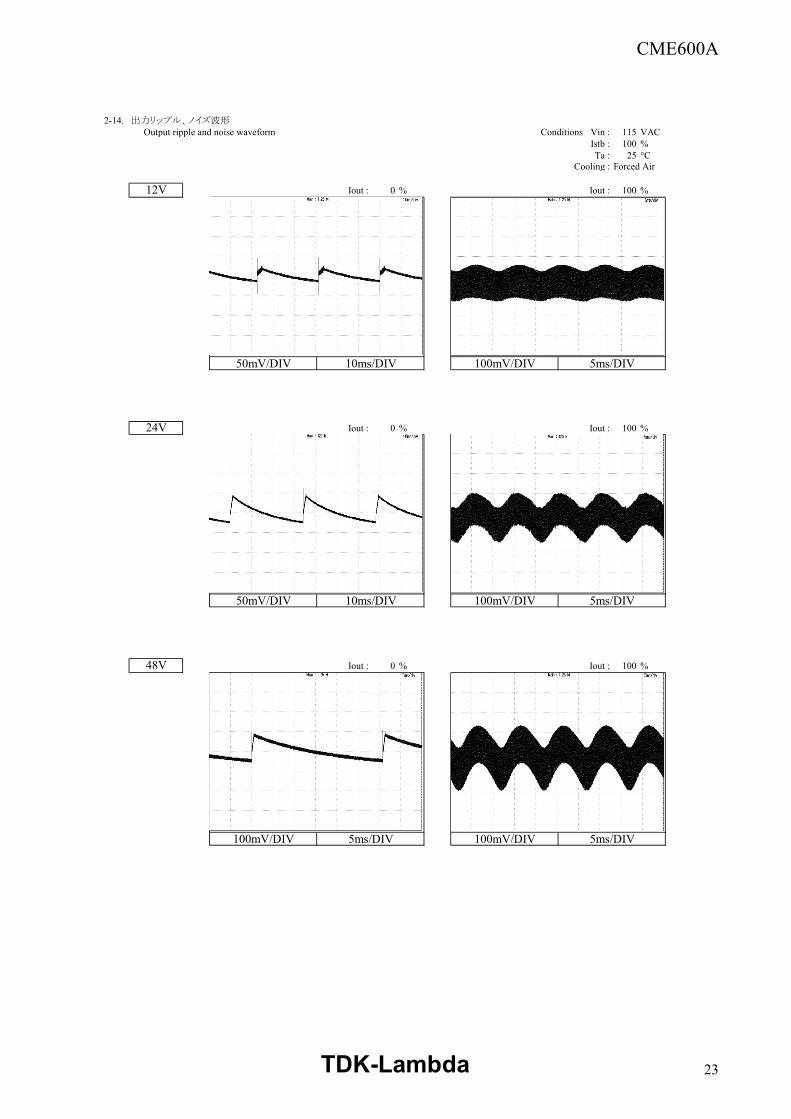
2-14. 出力リップル、ノイズ波形 Output ripple and noise waveform Conditions Vin : 115 VAC
Istb : 100 %Ta : 25 °C
Cooling : Forced Air
Iout : 0 % Iout : 100 %
50mV/DIV 10ms/DIV 100mV/DIV 5ms/DIV
Iout : 0 % Iout : 100 %
50mV/DIV 10ms/DIV 100mV/DIV 5ms/DIV
Iout : 0 % Iout : 100 %
100mV/DIV 5ms/DIV 100mV/DIV 5ms/DIV
12V
24V
48V
TDK-Lambda 23
CME600A
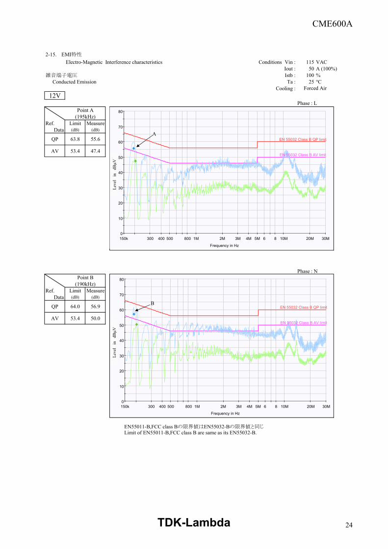
2-15. EMI特性
Electro-Magnetic Interference characteristics Conditions Vin : 115 VACIout : 50 A (100%)
雑音端子電圧 Istb : 100 % Conducted Emission Ta : 25 °C
Cooling :12V
Phase : LPoint A
(195kHz)Ref. Limit Measure
Data (dB) (dB)
QP 63.8 55.6
AV 53.4 47.4
Phase : NPoint B
(190kHz)Ref. Limit Measure
Data (dB) (dB)
QP 64.0 56.9
AV 53.4 50.0
EN55011-B,FCC class Bの限界値はEN55032-Bの限界値と同じLimit of EN55011-B,FCC class B are same as its EN55032-B.
Forced Air
0
10
20
30
40
50
60
70
80
150k 300 400 500 800 1M 2M 3M 4M 5M 6 8 10M 20M 30M
Leve
l in
dBµV
Frequency in Hz
EN 55032 Class B QP limit
EN 55032 Class B AV limit
0
10
20
30
40
50
60
70
80
150k 300 400 500 800 1M 2M 3M 4M 5M 6 8 10M 20M 30M
Leve
l in
dBµV
Frequency in Hz
EN 55032 Class B QP limit
EN 55032 Class B AV limit
A
B
Leve
l in
dB
µVLe
vel
in
dBµV
TDK-Lambda 24
CME600A
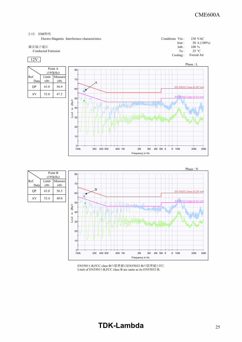
2-15. EMI特性
Electro-Magnetic Interference characteristics Conditions Vin : 230 VACIout : 50 A (100%)
雑音端子電圧 Istb : 100 % Conducted Emission Ta : 25 °C
Cooling :12V
Phase : LPoint A
(195kHz)Ref. Limit Measure
Data (dB) (dB)
QP 63.8 56.9
AV 53.8 47.2
Phase : NPoint B
(195kHz)Ref. Limit Measure
Data (dB) (dB)
QP 63.8 56.5
AV 53.4 49.0
EN55011-B,FCC class Bの限界値はEN55032-Bの限界値と同じLimit of EN55011-B,FCC class B are same as its EN55032-B.
Forced Air
0
10
20
30
40
50
60
70
80
150k 300 400 500 800 1M 2M 3M 4M 5M 6 8 10M 20M 30M
Leve
l in
dBµV
Frequency in Hz
EN 55032 Class B QP limit
EN 55032 Class B AV limit
0
10
20
30
40
50
60
70
80
150k 300 400 500 800 1M 2M 3M 4M 5M 6 8 10M 20M 30M
Leve
l in
dBµV
Frequency in Hz
EN 55032 Class B QP limit
EN 55032 Class B AV limit
A
B
Leve
l in
dB
µVLe
vel
in
dBµV
TDK-Lambda 25
CME600A
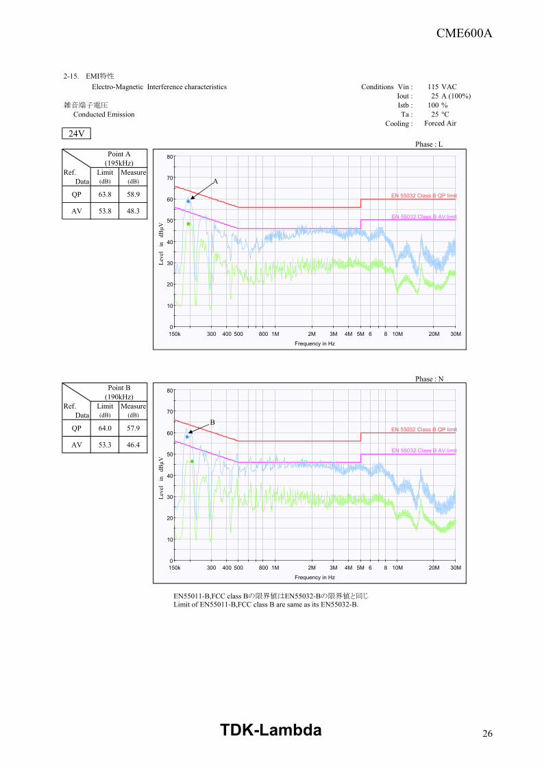
2-15. EMI特性
Electro-Magnetic Interference characteristics Conditions Vin : 115 VACIout : 25 A (100%)
雑音端子電圧 Istb : 100 % Conducted Emission Ta : 25 °C
Cooling :24V
Phase : LPoint A
(195kHz)Ref. Limit Measure
Data (dB) (dB)
QP 63.8 58.9
AV 53.8 48.3
Phase : NPoint B
(190kHz)Ref. Limit Measure
Data (dB) (dB)
QP 64.0 57.9
AV 53.3 46.4
EN55011-B,FCC class Bの限界値はEN55032-Bの限界値と同じLimit of EN55011-B,FCC class B are same as its EN55032-B.
Forced Air
0
10
20
30
40
50
60
70
80
150k 300 400 500 800 1M 2M 3M 4M 5M 6 8 10M 20M 30M
Leve
l in
dBµV
Frequency in Hz
EN 55032 Class B QP limit
EN 55032 Class B AV limit
0
10
20
30
40
50
60
70
80
150k 300 400 500 800 1M 2M 3M 4M 5M 6 8 10M 20M 30M
Leve
l in
dBµV
Frequency in Hz
EN 55032 Class B QP limit
EN 55032 Class B AV limit
A
B
Leve
l in
dB
µVLe
vel
in
dBµV
TDK-Lambda 26
CME600A
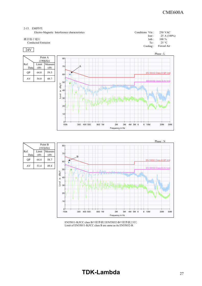
2-15. EMI特性
Electro-Magnetic Interference characteristics Conditions Vin : 230 VACIout : 25 A (100%)
雑音端子電圧 Istb : 100 % Conducted Emission Ta : 25 °C
Cooling :24V
Phase : LPoint A
(190kHz)Ref. Limit Measure
Data (dB) (dB)
QP 64.0 59.5
AV 54.0 48.7
Phase : NPoint B
(181kHz)Ref. Limit Measure
Data (dB) (dB)
QP 64.4 58.7
AV 53.4 49.4
EN55011-B,FCC class Bの限界値はEN55032-Bの限界値と同じLimit of EN55011-B,FCC class B are same as its EN55032-B.
Forced Air
0
10
20
30
40
50
60
70
80
150k 300 400 500 800 1M 2M 3M 4M 5M 6 8 10M 20M 30M
Leve
l in
dBµV
Frequency in Hz
EN 55032 Class B QP limit
EN 55032 Class B AV limit
0
10
20
30
40
50
60
70
80
150k 300 400 500 800 1M 2M 3M 4M 5M 6 8 10M 20M 30M
Leve
l in
dBµV
Frequency in Hz
EN 55032 Class B QP limit
EN 55032 Class B AV limit
A
B
Leve
l in
dB
µVLe
vel
in
dBµV
TDK-Lambda 27
CME600A
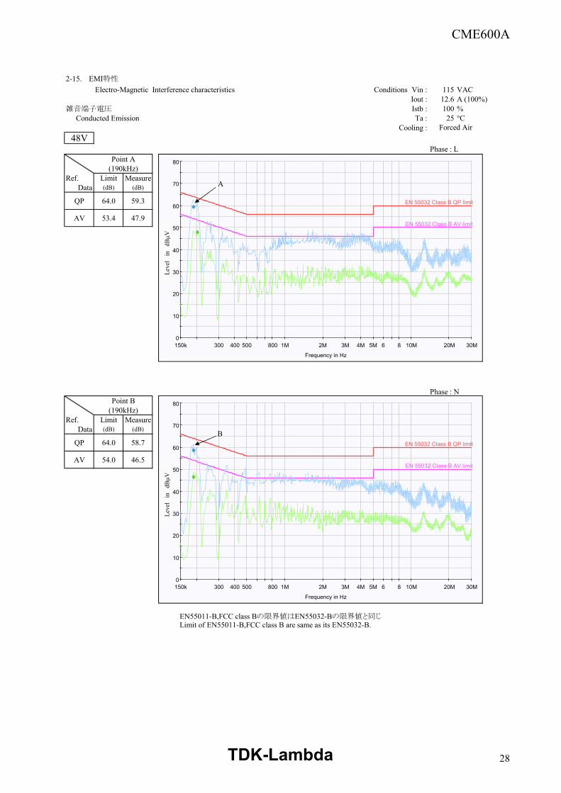
2-15. EMI特性
Electro-Magnetic Interference characteristics Conditions Vin : 115 VACIout : 12.6 A (100%)
雑音端子電圧 Istb : 100 % Conducted Emission Ta : 25 °C
Cooling :48V
Phase : LPoint A
(190kHz)Ref. Limit Measure
Data (dB) (dB)
QP 64.0 59.3
AV 53.4 47.9
Phase : NPoint B
(190kHz)Ref. Limit Measure
Data (dB) (dB)
QP 64.0 58.7
AV 54.0 46.5
EN55011-B,FCC class Bの限界値はEN55032-Bの限界値と同じLimit of EN55011-B,FCC class B are same as its EN55032-B.
Forced Air
0
10
20
30
40
50
60
70
80
150k 300 400 500 800 1M 2M 3M 4M 5M 6 8 10M 20M 30M
Leve
l in
dBµV
Frequency in Hz
EN 55032 Class B QP limit
EN 55032 Class B AV limit
0
10
20
30
40
50
60
70
80
150k 300 400 500 800 1M 2M 3M 4M 5M 6 8 10M 20M 30M
Leve
l in
dBµV
Frequency in Hz
EN 55032 Class B QP limit
EN 55032 Class B AV limit
A
B
Leve
l in
dB
µVLe
vel
in
dBµV
TDK-Lambda 28
CME600A
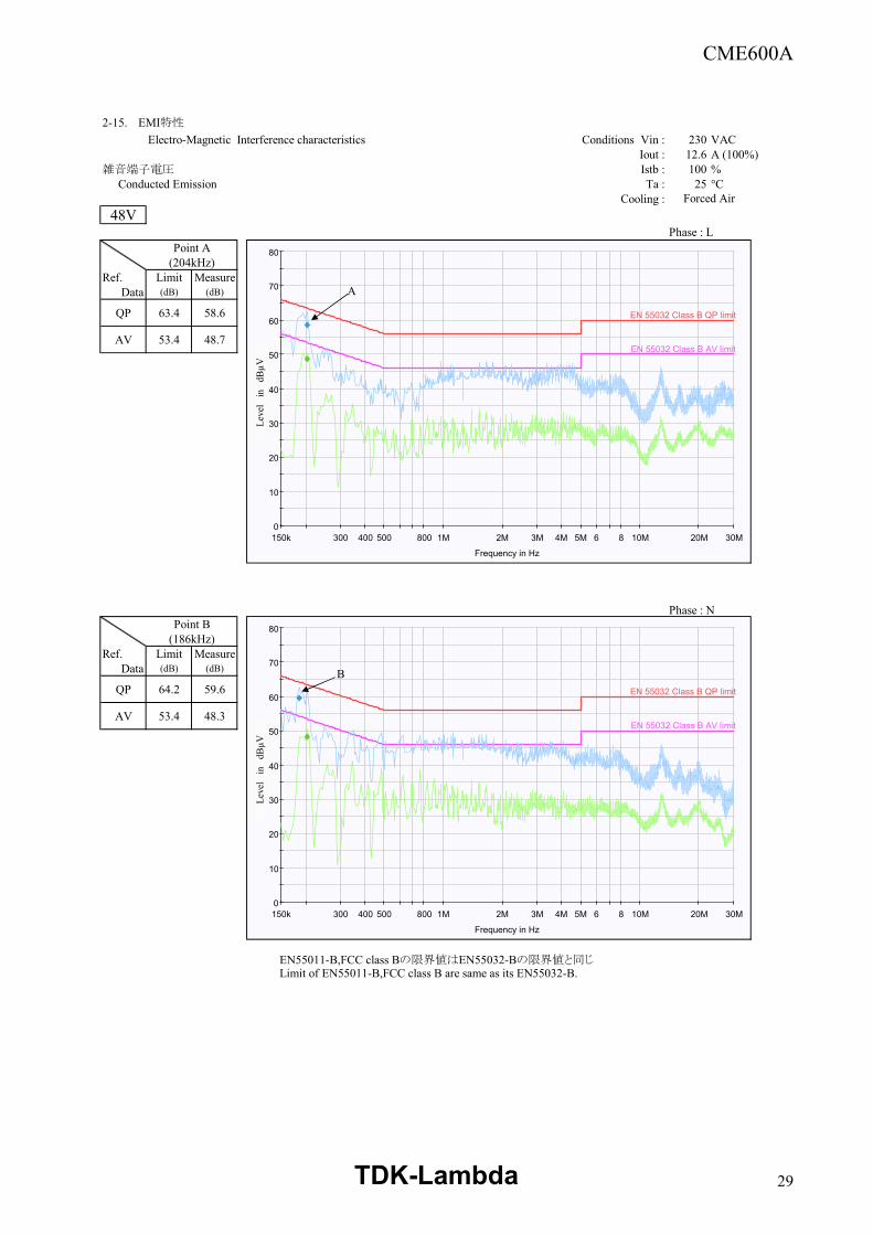
2-15. EMI特性
Electro-Magnetic Interference characteristics Conditions Vin : 230 VACIout : 12.6 A (100%)
雑音端子電圧 Istb : 100 % Conducted Emission Ta : 25 °C
Cooling :48V
Phase : LPoint A
(204kHz)Ref. Limit Measure
Data (dB) (dB)
QP 63.4 58.6
AV 53.4 48.7
Phase : NPoint B
(186kHz)Ref. Limit Measure
Data (dB) (dB)
QP 64.2 59.6
AV 53.4 48.3
EN55011-B,FCC class Bの限界値はEN55032-Bの限界値と同じLimit of EN55011-B,FCC class B are same as its EN55032-B.
Forced Air
0
10
20
30
40
50
60
70
80
150k 300 400 500 800 1M 2M 3M 4M 5M 6 8 10M 20M 30M
Leve
l in
dBµV
Frequency in Hz
EN 55032 Class B QP limit
EN 55032 Class B AV limit
0
10
20
30
40
50
60
70
80
150k 300 400 500 800 1M 2M 3M 4M 5M 6 8 10M 20M 30M
Leve
l in
dBµV
Frequency in Hz
EN 55032 Class B QP limit
EN 55032 Class B AV limit
A
B
Leve
l in
dB
µVLe
vel
in
dBµV
TDK-Lambda 29
CME600A
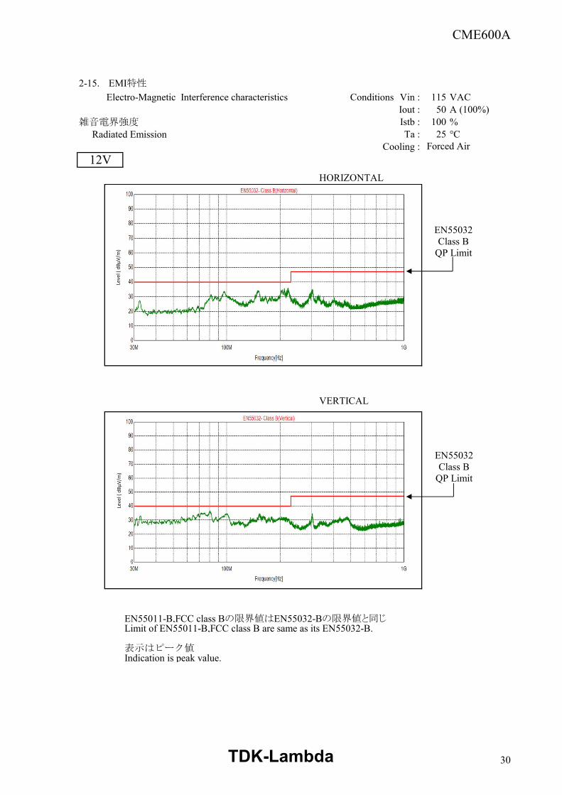
2-15. EMI特性
Electro-Magnetic Interference characteristics Conditions Vin : 115 VACIout : 50 A (100%)
雑音電界強度 Istb : 100 % Radiated Emission Ta : 25 °C
Cooling :
HORIZONTAL
VERTICAL
EN55011-B,FCC class Bの限界値はEN55032-Bの限界値と同じLimit of EN55011-B,FCC class B are same as its EN55032-B.
表示はピーク値Indication is peak value.
12VForced Air
Leve
l ( d
BµV/
m)
EN55032 Class B
QP Limit
Leve
l ( d
BµV/
m)
EN55032 Class B
QP Limit
TDK-Lambda 30
CME600A
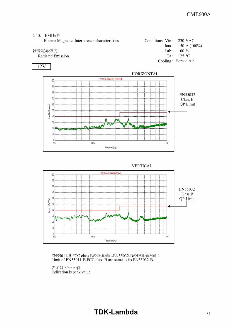
2-15. EMI特性Electro-Magnetic Interference characteristics Conditions Vin : 230 VAC
Iout : 50 A (100%)雑音電界強度 Istb : 100 % Radiated Emission Ta : 25 °C
Cooling :
HORIZONTAL
VERTICAL
EN55011-B,FCC class Bの限界値はEN55032-Bの限界値と同じLimit of EN55011-B,FCC class B are same as its EN55032-B.
表示はピーク値Indication is peak value.
12VForced Air
Leve
l ( d
BµV/
m)
Leve
l ( d
BµV/
m)
EN55032 Class B
QP Limit
EN55032 Class B
QP Limit
TDK-Lambda 31
CME600A
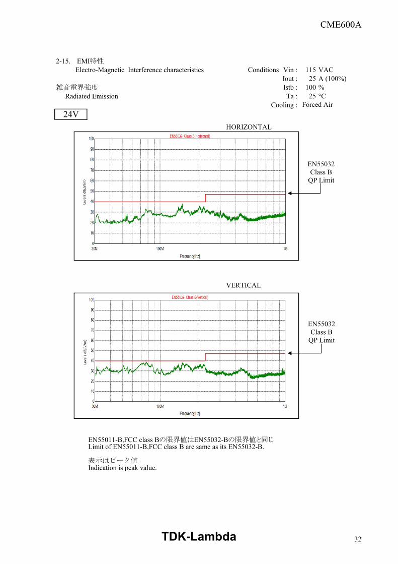
2-15. EMI特性Electro-Magnetic Interference characteristics Conditions Vin : 115 VAC
Iout : 25 A (100%)雑音電界強度 Istb : 100 % Radiated Emission Ta : 25 °C
Cooling :
HORIZONTAL
VERTICAL
EN55011-B,FCC class Bの限界値はEN55032-Bの限界値と同じLimit of EN55011-B,FCC class B are same as its EN55032-B.
表示はピーク値Indication is peak value.
Forced Air24V
Leve
l ( d
BµV/
m)
Leve
l ( d
BµV/
m)
EN55032 Class B
QP Limit
EN55032 Class B
QP Limit
TDK-Lambda 32
CME600A
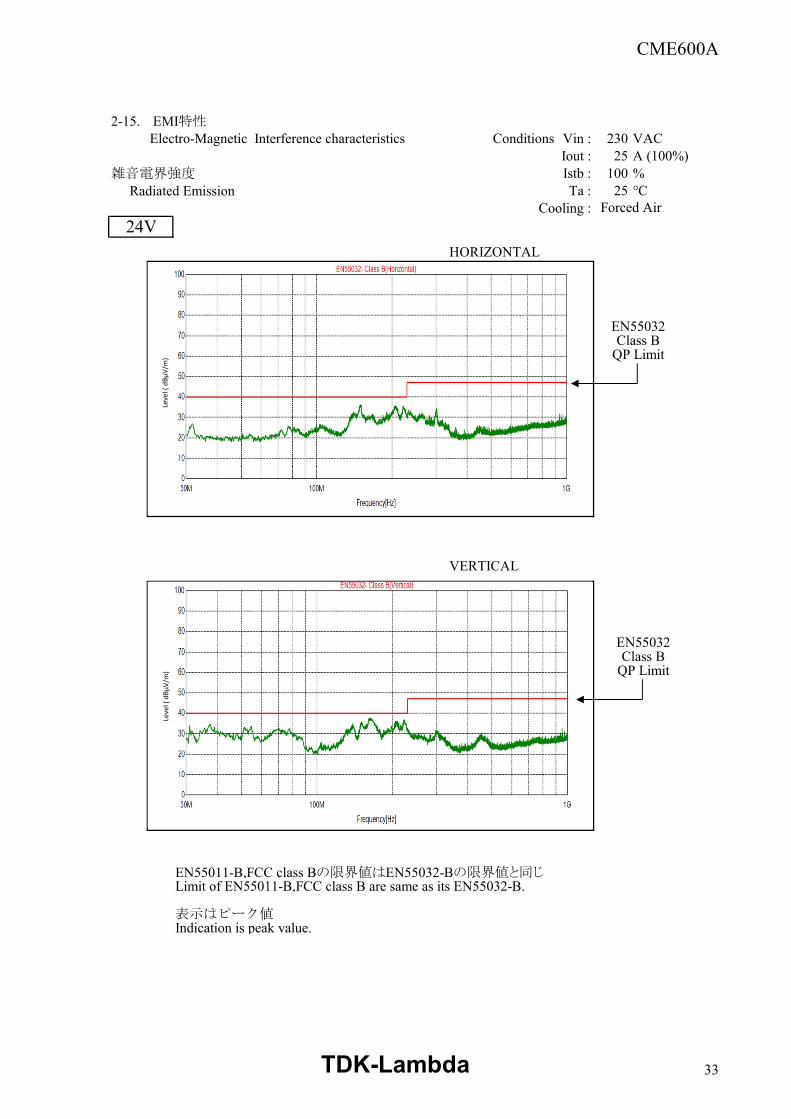
2-15. EMI特性Electro-Magnetic Interference characteristics Conditions Vin : 230 VAC
Iout : 25 A (100%)雑音電界強度 Istb : 100 % Radiated Emission Ta : 25 °C
Cooling :
HORIZONTAL
VERTICAL
EN55011-B,FCC class Bの限界値はEN55032-Bの限界値と同じLimit of EN55011-B,FCC class B are same as its EN55032-B.
表示はピーク値Indication is peak value.
Forced Air24V
Leve
l ( d
BµV/
m)
EN55032 Class B
QP Limit
Leve
l ( d
BµV/
m)
EN55032 Class B
QP Limit
TDK-Lambda 33
CME600A
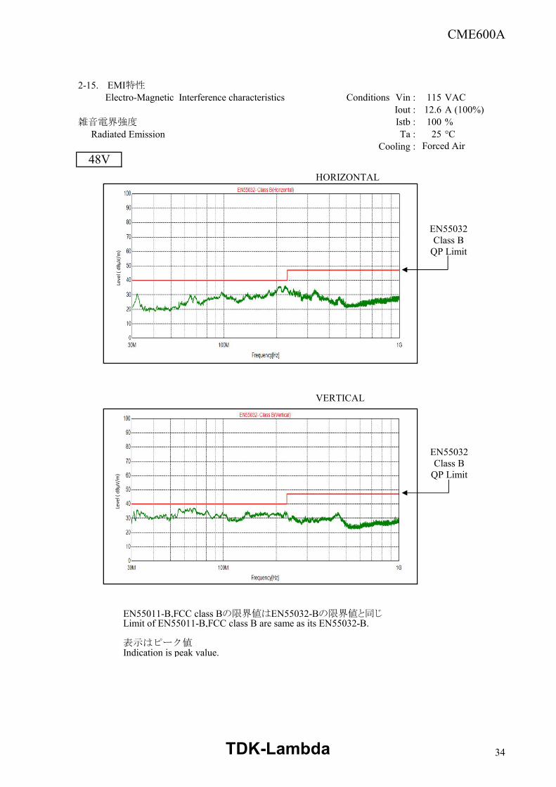
2-15. EMI特性Electro-Magnetic Interference characteristics Conditions Vin : 115 VAC
Iout : 12.6 A (100%)雑音電界強度 Istb : 100 % Radiated Emission Ta : 25 °C
Cooling :
HORIZONTAL
VERTICAL
EN55011-B,FCC class Bの限界値はEN55032-Bの限界値と同じLimit of EN55011-B,FCC class B are same as its EN55032-B.
表示はピーク値Indication is peak value.
Forced Air48V
Leve
l ( d
BµV/
m)
Leve
l ( d
BµV/
m)
EN55032 Class B
QP Limit
EN55032 Class B
QP Limit
TDK-Lambda 34
CME600A
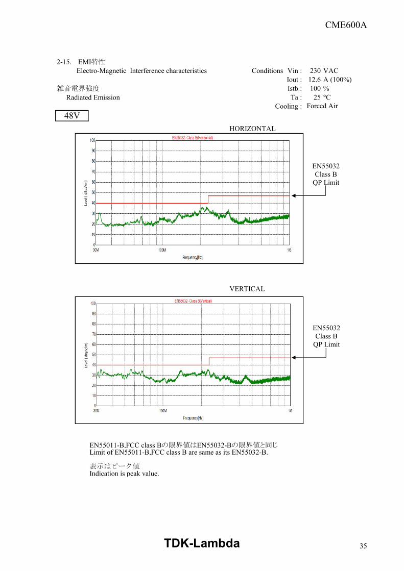
2-15. EMI特性Electro-Magnetic Interference characteristics Conditions Vin : 230 VAC
Iout : 12.6 A (100%)雑音電界強度 Istb : 100 % Radiated Emission Ta : 25 °C
Cooling :
HORIZONTAL
VERTICAL
EN55011-B,FCC class Bの限界値はEN55032-Bの限界値と同じLimit of EN55011-B,FCC class B are same as its EN55032-B.
表示はピーク値Indication is peak value.
Forced Air48V
Leve
l ( d
BµV/
m)
Leve
l ( d
BµV/
m)
EN55032 Class B
QP Limit
EN55032 Class B
QP Limit
TDK-Lambda 35