CMC TECHNICAL REFERENCE MANUALmanualarchive.ingersollrandproducts.com/manuals/manuals/... · Alarm...
176
INGERSOLL-RAND INGERSOLL-RAND AIR COMPRESSORS CENTAC CMC TECHNICAL REFERENCE MANUAL (Part No. 22204796)
Transcript of CMC TECHNICAL REFERENCE MANUALmanualarchive.ingersollrandproducts.com/manuals/manuals/... · Alarm...
INGERSOLL-RAND
INGERSOLL-RAND AIR COMPRESSORS
CENTAC
CMC TECHNICAL REFERENCE MANUAL (Part No. 22204796)

CMC TECHNICAL REFERENCE MANUAL
22204796 Rev. B, Version 3.10 1996-2003 Ingersoll-Rand Company Date of Issue: March 24, 2003
Copyright Notice
Copyright 1996-2003 Ingersoll-Rand Company THIS MANUAL IS SOLD "AS IS" AND WITHOUT ANY EXPRESSED OR IMPLIED WARRANTIES WHATSOEVER. Printing Date: 24 March 2003 Ingersoll-Rand air compressors are not designed, intended, or approved for breathing air applications. Ingersoll-Rand does not approve specialized equipment for breathing air applications and assumes no responsibility or liability for compressors used for breathing air service.

CMC TECHNICAL REFERENCE MANUAL
22204796 Rev. B, Version 3.10 1996-2003 Ingersoll-Rand Company Date of Issue: March 24, 2003
Table of Contents What’s New About the 3.10 Release ______________________________________1
References ___________________________________________________________2
General - CMC Panel ___________________________________________________3
Control Methodology___________________________________________________4 Performance Control _______________________________________________________4 PID Control _______________________________________________________________7 Surge Control ____________________________________________________________12 Prelube Pump ____________________________________________________________18 Oil Heater _______________________________________________________________18
Protection and Monitoring _____________________________________________19 Analog Functions _________________________________________________________19 Digital Functions _________________________________________________________19
Compressor Operating Methodology ____________________________________21 Stopped _________________________________________________________________21 Rotating_________________________________________________________________21 Compressor Operating States ______________________________________________23 OUI (Operator User Interface) _______________________________________________24 General Sequence of Operation _____________________________________________41 Indicator, Switch and Light Layout___________________________________________42
CMC Tuning Procedures_______________________________________________42 Setting MaxLoad__________________________________________________________42 Setting MinLoad __________________________________________________________43 Setting MinLoad Surge Index Increment ______________________________________44 Setting Surge Sensitivity ___________________________________________________44 Tuning Stability __________________________________________________________45 Calibrating the Control Valves ______________________________________________46 Autodual Control Settings__________________________________________________47 Setting the Start Time _____________________________________________________48 Setting the CT Ratio _______________________________________________________48 Inlet Unload Position ______________________________________________________48 Setting Set Point Ramp Rate________________________________________________48 Alarm and Trip Settings____________________________________________________49
CMC TECHNICAL REFERENCE MANUAL
22204796 Rev. B, Version 3.10 1996-2003 Ingersoll-Rand Company
Date of Issue: March 24, 2003
Troubleshooting _____________________________________________________50 Troubleshooting Example __________________________________________________51 Input/Output (I/O) System __________________________________________________52 Control Power System (CPS) _______________________________________________72 Controller Problems_______________________________________________________76
Options _____________________________________________________________78 Enclosures ______________________________________________________________78 Control Electrical Package _________________________________________________80 Stage Data Package _______________________________________________________80 Alarm Horn ______________________________________________________________80 Running Unloaded Shutdown Timer _________________________________________80 Water Solenoid Post Run Timer _____________________________________________80 Panel Mounted Wye-Delta Starter____________________________________________80 N.O. Contact for Remote Indication of Common Alarm and Trip __________________80 Power Regulating Constant Voltage Transformer ______________________________80 Automatic Starting ________________________________________________________81 Remote 4-20 mA Pressure Setpoint __________________________________________82 Ambient Control plus Parallel Valve Control Logic _____________________________82 Mass Flow Control ________________________________________________________84 Steam and Gas Turbine Driven Compressors__________________________________85 Diesel Driven Compressors ________________________________________________92
Communication ______________________________________________________93 Human Machine Interface (HMI) Systems _____________________________________93 Direct CMC Communications with RS422/485__________________________________93 The CMC-MODBUS Interface________________________________________________94 The CMC-DF1 Interface ___________________________________________________115
Documentation______________________________________________________143
System Information __________________________________________________143 Status Codes ___________________________________________________________143 Base Control Module (BCM) _______________________________________________145 Operator User Interface Module (OUI) _______________________________________148 Universal Communication Module (UCM) Optional ____________________________152
Technical Specification_______________________________________________160
Glossary _____________________________________________________________1
CMC TECHNICAL REFERENCE MANUAL
22204796 Rev. B, Version 3.10 1996-2003 Ingersoll-Rand Company Date of Issue: March 24, 2003
Table of Figures Figure 1: Compressed Air System................................................................................................................ 4 Figure 2: Modulate Control .......................................................................................................................... 5 Figure 3: Autodual Control ........................................................................................................................... 5 Figure 4: Performance Control..................................................................................................................... 6 Figure 5: Prpportional Band, Pb................................................................................................................... 7 Figure 6: Proportional Plus Integral Control................................................................................................. 8 Figure 9: MinLoad and MaxLoad ............................................................................................................... 10 Figure 14: Rise to Surge ............................................................................................................................ 14 Figure 15: Changes in Discharge Pressure............................................................................................... 14 Figure 16: Surge Detection System............................................................................................................ 16 Figure 18: Plant Air System ........................................................................................................................ 42 Figure 19: Troubleshooting Tree................................................................................................................. 50 Figure 21: Measuring Flow ......................................................................................................................... 85 Figure 22: MODBUS Messages................................................................................................................. 95

CMC TECHNICAL REFERENCE MANUAL
22204796 Rev. B, Version 3.10 1996-2003 Ingersoll-Rand Company Date of Issue: March 24, 2003
1
What’s New About the 3.10 Release This is the initial release of the CMC Manual for version 3.10. This version was created to support new features incorporated into the CMC Product, and provide additional information compared with previous versions. Specifically, new features are as follows: 1. PID Scaling, p.9 2. Valve Characterization, p.15 3. Ambient Control plus Parallel Valve Control Logic, p.82 4. Mass Flow Control, p.84 5. Support for new, high speed IR-Bus at 38.4 kbps 6. Processor upgraded from 16 MHz to 25 MHz on Base Control Module (BCM) 7. Replaceable fuse (F2) for display, p.149 8. Operator instructions on display, p.35 9. “Pop-up” window to provide useful customer information, p.28
2 CMC TECHNICAL REFERENCE MANUAL
22204796 Rev. B, Version 3.10 1996-2003 Ingersoll-Rand Company
Date of Issue: March 24, 2003
References The following references were used in creating this document. All of this documentation is recommended for a more detailed understanding of specific control modes and control panel functions.
NEMA STANDARDS PUBLICATION NO. 250, Enclosures for Electrical Equipment (1000 Volts
Maximum), Revision 2, May 1988 NFPA 496 Standard for Purged and Pressurized Enclosures for Electrical Equipment, 1986
Edition Nisenfeld, A. Eli, Centrifugal Compressors: Principles of Operation and Control, Instrument
Society of America, 1982 Moore, Ralph L., Control of Centrifugal Compressors, Instrument Society of America, 1989 Doebelin, Ernest O., Control System Principles and Design, John Wiley & Sons, 1985 Rowland, James R., Linear Control Systems Modeling, Analysis, and Design, John Wiley &
Sons, 1986 Deshpande, Pradeep B. and Ash, Raymond H., Computer Process Control With Advanced
Control Applications, 2nd Edition, Instrument Society of America, 1988 CENTAC ENERGY MASTER, Version CEM230, Ingersoll-Rand Company, March 1992 White, M.H., Surge Control for Centrifugal Compressors, Chemical Engineering, December 25,
1972 Hall, James W., THERMODYNAMICS OF COMPRESSION: A Review of Fundamentals,
Instrument Society of America, 1976 Gaston, John R., Centrifugal Compressor Operation & Control: Part II "Compressor Operation",
Instrument Society of America, 1976 Gaston, John R., Antisurge Control Schemes For Turbocompressors, Chemical Engineering,
April 1982 Warnock, J. D., Methods for Control of Centrifugal and Reciprocating Compressors, Moore
Products, 1984 Harrison, Howard L. and Bollinger, John G., Introduction to Automatic Controls, Second Edition,
Harper & Row, 1969
CMC TECHNICAL REFERENCE MANUAL 3
22204796 Rev. B, Version 3.10 1996-2003 Ingersoll-Rand Company Date of Issue: March 24, 2003
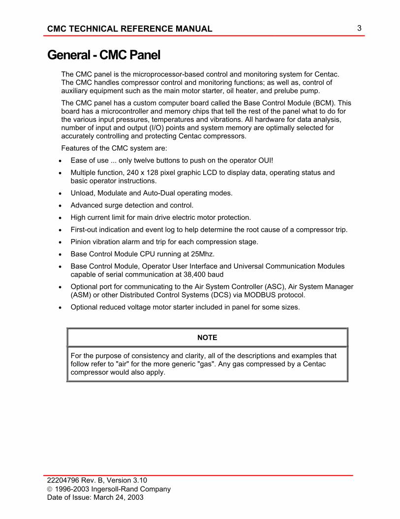
General - CMC Panel The CMC panel is the microprocessor-based control and monitoring system for Centac. The CMC handles compressor control and monitoring functions; as well as, control of auxiliary equipment such as the main motor starter, oil heater, and prelube pump. The CMC panel has a custom computer board called the Base Control Module (BCM). This board has a microcontroller and memory chips that tell the rest of the panel what to do for the various input pressures, temperatures and vibrations. All hardware for data analysis, number of input and output (I/O) points and system memory are optimally selected for accurately controlling and protecting Centac compressors. Features of the CMC system are:
• Ease of use ... only twelve buttons to push on the operator OUI! • Multiple function, 240 x 128 pixel graphic LCD to display data, operating status and
basic operator instructions. • Unload, Modulate and Auto-Dual operating modes. • Advanced surge detection and control. • High current limit for main drive electric motor protection. • First-out indication and event log to help determine the root cause of a compressor trip. • Pinion vibration alarm and trip for each compression stage. • Base Control Module CPU running at 25Mhz. • Base Control Module, Operator User Interface and Universal Communication Modules
capable of serial communication at 38,400 baud • Optional port for communicating to the Air System Controller (ASC), Air System Manager
(ASM) or other Distributed Control Systems (DCS) via MODBUS protocol. • Optional reduced voltage motor starter included in panel for some sizes.
NOTE
For the purpose of consistency and clarity, all of the descriptions and examples that follow refer to "air" for the more generic "gas". Any gas compressed by a Centac compressor would also apply.
4 CMC TECHNICAL REFERENCE MANUAL
22204796 Rev. B, Version 3.10 1996-2003 Ingersoll-Rand Company
Date of Issue: March 24, 2003
Control Methodology The CMC utilizes performance and surge control methodologies to meet varying compressed air system needs. The term "performance control" is used for grouping the control modes that affect compressor power consumption through movement of the intake and discharge valves.
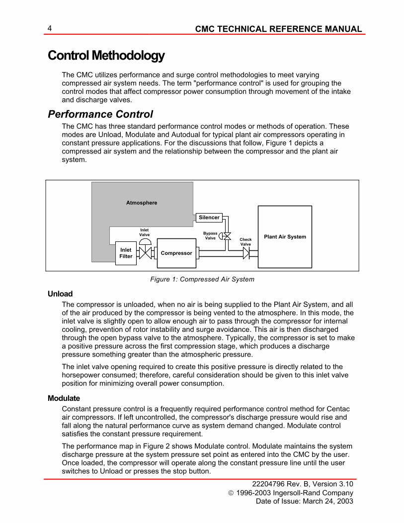
Performance Control The CMC has three standard performance control modes or methods of operation. These modes are Unload, Modulate and Autodual for typical plant air compressors operating in constant pressure applications. For the discussions that follow, Figure 1 depicts a compressed air system and the relationship between the compressor and the plant air system.
Compressor
Plant Air SystemInlet
Valve BypassValve Check
ValveInletFilter
Silencer
Atmosphere
Figure 1: Compressed Air System
Unload The compressor is unloaded, when no air is being supplied to the Plant Air System, and all of the air produced by the compressor is being vented to the atmosphere. In this mode, the inlet valve is slightly open to allow enough air to pass through the compressor for internal cooling, prevention of rotor instability and surge avoidance. This air is then discharged through the open bypass valve to the atmosphere. Typically, the compressor is set to make a positive pressure across the first compression stage, which produces a discharge pressure something greater than the atmospheric pressure. The inlet valve opening required to create this positive pressure is directly related to the horsepower consumed; therefore, careful consideration should be given to this inlet valve position for minimizing overall power consumption.
Modulate Constant pressure control is a frequently required performance control method for Centac air compressors. If left uncontrolled, the compressor's discharge pressure would rise and fall along the natural performance curve as system demand changed. Modulate control satisfies the constant pressure requirement. The performance map in Figure 2 shows Modulate control. Modulate maintains the system discharge pressure at the system pressure set point as entered into the CMC by the user. Once loaded, the compressor will operate along the constant pressure line until the user switches to Unload or presses the stop button.
CMC TECHNICAL REFERENCE MANUAL 5
22204796 Rev. B, Version 3.10 1996-2003 Ingersoll-Rand Company Date of Issue: March 24, 2003
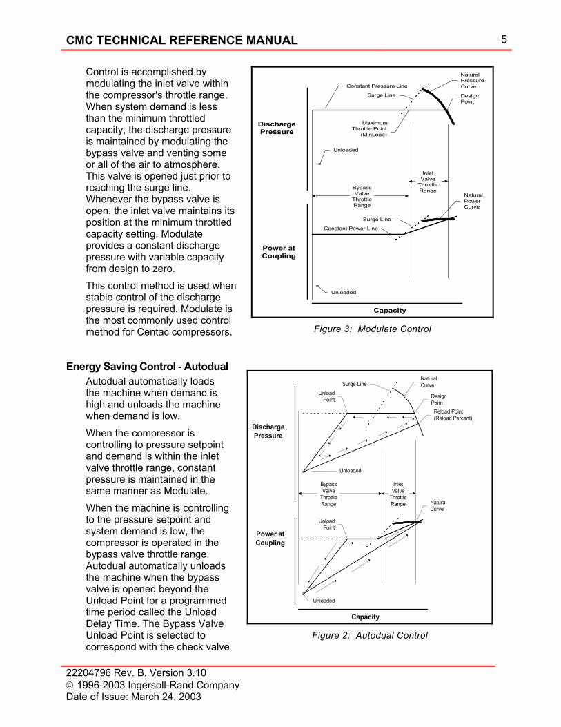
Control is accomplished by modulating the inlet valve within the compressor's throttle range. When system demand is less than the minimum throttled capacity, the discharge pressure is maintained by modulating the bypass valve and venting some or all of the air to atmosphere. This valve is opened just prior to reaching the surge line. Whenever the bypass valve is open, the inlet valve maintains its position at the minimum throttled capacity setting. Modulate provides a constant discharge pressure with variable capacity from design to zero. This control method is used when stable control of the discharge pressure is required. Modulate is the most commonly used control method for Centac compressors.
Energy Saving Control - Autodual Autodual automatically loads the machine when demand is high and unloads the machine when demand is low. When the compressor is controlling to pressure setpoint and demand is within the inlet valve throttle range, constant pressure is maintained in the same manner as Modulate. When the machine is controlling to the pressure setpoint and system demand is low, the compressor is operated in the bypass valve throttle range. Autodual automatically unloads the machine when the bypass valve is opened beyond the Unload Point for a programmed time period called the Unload Delay Time. The Bypass Valve Unload Point is selected to correspond with the check valve
DischargePressure
Power atCoupling
Capacity
Surge LineNaturalCurve
DesignPoint
NaturalCurve
UnloadPoint
Unloaded
Unloaded
InletValve
ThrottleRange
BypassValve
ThrottleRange
Reload Point(Reload Percent)
UnloadPoint
Figure 2: Autodual Control
DischargePressure
Power atCoupling
Capacity
InletValve
ThrottleRange
Surge Line
NaturalPressureCurve
DesignPoint
MaximumThrottle Point
(MinLoad)
Constant Pressure Line
Unloaded
BypassValve
ThrottleRange
NaturalPowerCurve
Surge Line
Constant Power Line
Unloaded
Figure 3: Modulate Control
6 CMC TECHNICAL REFERENCE MANUAL
22204796 Rev. B, Version 3.10 1996-2003 Ingersoll-Rand Company
Date of Issue: March 24, 2003
closing since at this point the machine is not supplying the system (Figure 3). The Unload Delay Timer should be set to prevent unloading during short excursions through the Unload Point. The Reload Percent determines the System Pressure at which the machine will automatically load into the system.
How does Constant Pressure Modulation Work? The goal of constant pressure modulation is to maintain a specified discharge pressure in the compressed air system while the capacity requirements change. Modulate control provides constant pressure from 100 percent of the compressor's capacity to zero capacity. Autodual control provides constant pressure from the 100 percent of the compressor's capacity to the Unload Point. If all plant air systems were identical in capacity usage requirements, the CMC could be preprogrammed to respond to those changes; however, all plant air systems are not alike. The frequency and variability of the capacity changes means that the control logic must be flexible, so the CMC utilizes proportional, integral and derivative control algorithms to determine the magnitude of the signal that is sent to the inlet and bypass valves. These algorithms, or programming logic, allow the CMC control system to be "tuned" to a specific plant air system.
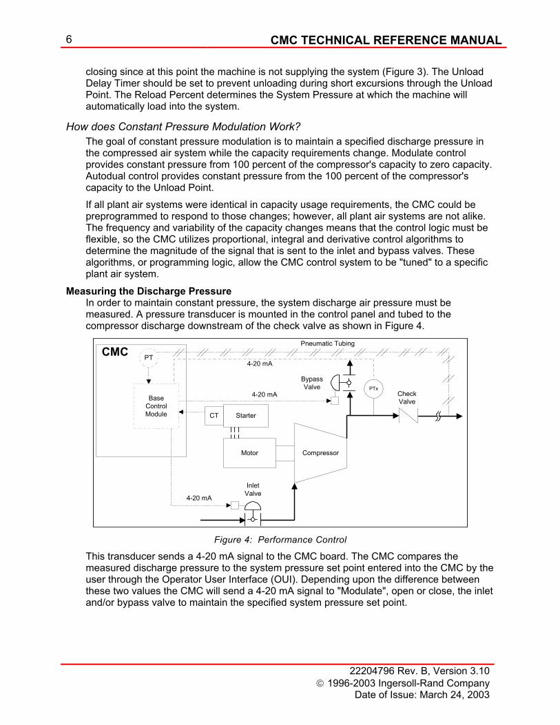
Measuring the Discharge Pressure In order to maintain constant pressure, the system discharge air pressure must be measured. A pressure transducer is mounted in the control panel and tubed to the compressor discharge downstream of the check valve as shown in Figure 4.
CompressorMotor
StarterCT
BypassValve
InletValve
CheckValveBase
ControlModule
PT
4-20 mA
4-20 mA
CMCPneumatic Tubing
PTx
4-20 mA
Figure 4: Performance Control
This transducer sends a 4-20 mA signal to the CMC board. The CMC compares the measured discharge pressure to the system pressure set point entered into the CMC by the user through the Operator User Interface (OUI). Depending upon the difference between these two values the CMC will send a 4-20 mA signal to "Modulate", open or close, the inlet and/or bypass valve to maintain the specified system pressure set point.
CMC TECHNICAL REFERENCE MANUAL 7
22204796 Rev. B, Version 3.10 1996-2003 Ingersoll-Rand Company Date of Issue: March 24, 2003
PID Control Proportional Band
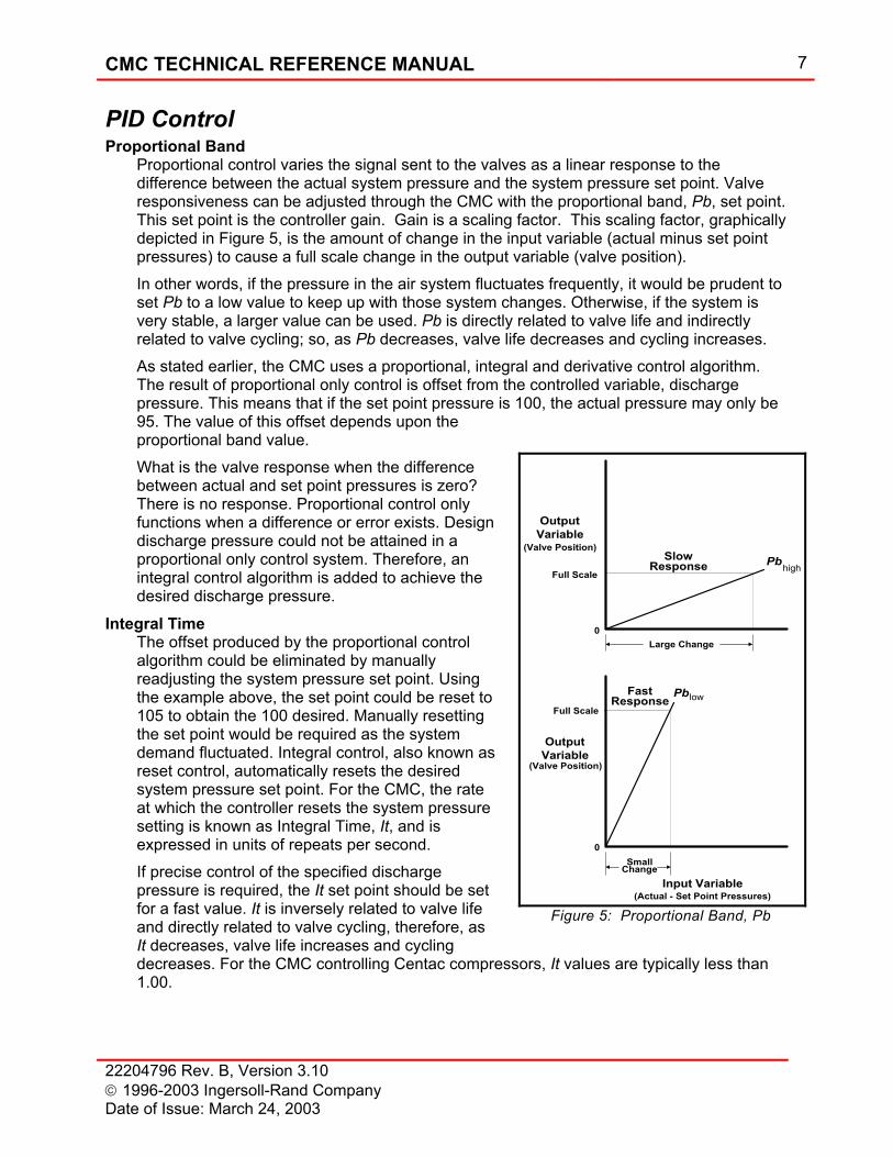
Proportional control varies the signal sent to the valves as a linear response to the difference between the actual system pressure and the system pressure set point. Valve responsiveness can be adjusted through the CMC with the proportional band, Pb, set point. This set point is the controller gain. Gain is a scaling factor. This scaling factor, graphically depicted in Figure 5, is the amount of change in the input variable (actual minus set point pressures) to cause a full scale change in the output variable (valve position). In other words, if the pressure in the air system fluctuates frequently, it would be prudent to set Pb to a low value to keep up with those system changes. Otherwise, if the system is very stable, a larger value can be used. Pb is directly related to valve life and indirectly related to valve cycling; so, as Pb decreases, valve life decreases and cycling increases. As stated earlier, the CMC uses a proportional, integral and derivative control algorithm. The result of proportional only control is offset from the controlled variable, discharge pressure. This means that if the set point pressure is 100, the actual pressure may only be 95. The value of this offset depends upon the proportional band value. What is the valve response when the difference between actual and set point pressures is zero? There is no response. Proportional control only functions when a difference or error exists. Design discharge pressure could not be attained in a proportional only control system. Therefore, an integral control algorithm is added to achieve the desired discharge pressure.
Integral Time The offset produced by the proportional control algorithm could be eliminated by manually readjusting the system pressure set point. Using the example above, the set point could be reset to 105 to obtain the 100 desired. Manually resetting the set point would be required as the system demand fluctuated. Integral control, also known as reset control, automatically resets the desired system pressure set point. For the CMC, the rate at which the controller resets the system pressure setting is known as Integral Time, It, and is expressed in units of repeats per second. If precise control of the specified discharge pressure is required, the It set point should be set for a fast value. It is inversely related to valve life and directly related to valve cycling, therefore, as It decreases, valve life increases and cycling decreases. For the CMC controlling Centac compressors, It values are typically less than 1.00.
OutputVariable
(Valve Position)Pbhigh
Full Scale
0Large Change
OutputVariable
(Valve Position)
Input Variable(Actual - Set Point Pressures)
PblowFull Scale
0Small
Change
Slow
FastResponse
Response
Figure 5: Proportional Band, Pb
8 CMC TECHNICAL REFERENCE MANUAL
22204796 Rev. B, Version 3.10 1996-2003 Ingersoll-Rand Company
Date of Issue: March 24, 2003
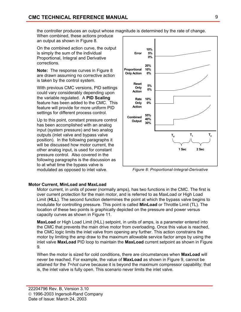
Erro
r
Proportional ComponentCon
trol
ler
Out
put
Derivative Component
Time Figure 7; PD Controller
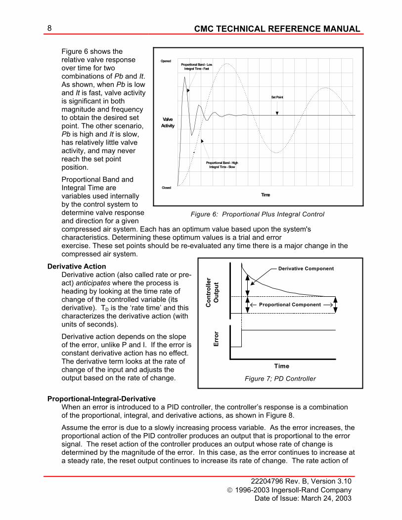
Figure 6 shows the relative valve response over time for two combinations of Pb and It. As shown, when Pb is low and It is fast, valve activity is significant in both magnitude and frequency to obtain the desired set point. The other scenario, Pb is high and It is slow, has relatively little valve activity, and may never reach the set point position. Proportional Band and Integral Time are variables used internally by the control system to determine valve response and direction for a given compressed air system. Each has an optimum value based upon the system's characteristics. Determining these optimum values is a trial and error exercise. These set points should be re-evaluated any time there is a major change in the compressed air system.
Derivative Action Derivative action (also called rate or pre-act) anticipates where the process is heading by looking at the time rate of change of the controlled variable (its derivative). TD is the ‘rate time’ and this characterizes the derivative action (with units of seconds). Derivative action depends on the slope of the error, unlike P and I. If the error is constant derivative action has no effect. The derivative term looks at the rate of change of the input and adjusts the output based on the rate of change.
Proportional-Integral-Derivative
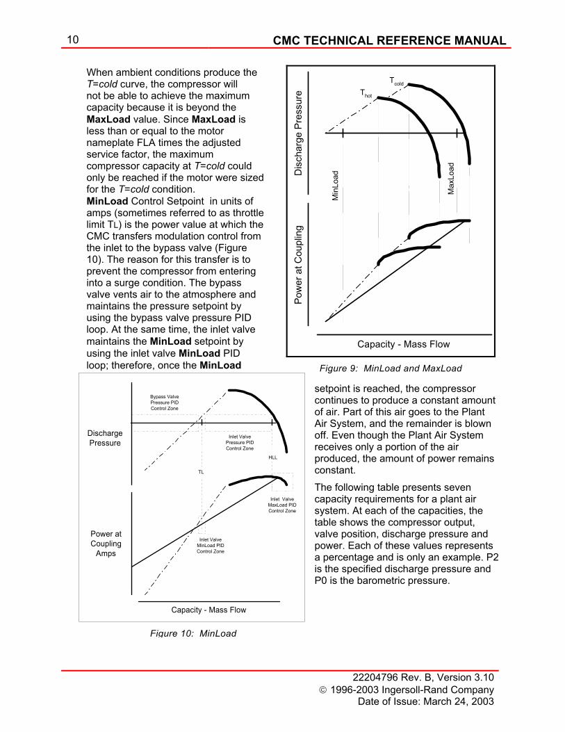
When an error is introduced to a PID controller, the controller’s response is a combination of the proportional, integral, and derivative actions, as shown in Figure 8. Assume the error is due to a slowly increasing process variable. As the error increases, the proportional action of the PID controller produces an output that is proportional to the error signal. The reset action of the controller produces an output whose rate of change is determined by the magnitude of the error. In this case, as the error continues to increase at a steady rate, the reset output continues to increase its rate of change. The rate action of
Time
ValveActivity
Proportional Band - LowIntegral Time - Fast
Proportional Band - HighIntegral Time - Slow
Closed
Opened
Set Point
Figure 6: Proportional Plus Integral Control
CMC TECHNICAL REFERENCE MANUAL 9
22204796 Rev. B, Version 3.10 1996-2003 Ingersoll-Rand Company Date of Issue: March 24, 2003
the controller produces an output whose magnitude is determined by the rate of change. When combined, these actions produce an output as shown in Figure 8. On the combined action curve, the output is simply the sum of the individual Proportional, Integral and Derivative corrections.
Note: The response curves in Figure 8 are drawn assuming no corrective action is taken by the control system. With previous CMC versions, PID settings could vary considerably depending upon the variable regulated. A PID Scaling feature has been added to the CMC. This feature will provide for more uniform PID settings for different process control. Up to this point, constant pressure control has been accomplished with an analog input (system pressure) and two analog outputs (inlet valve and bypass valve position). In the following paragraphs it will be discussed how motor current, the other analog input, is used for constant pressure control. Also covered in the following paragraphs is the discussion as to at what time the bypass valve is modulated as opposed to inlet valve.
Motor Current, MinLoad and MaxLoad Motor current, in units of power (normally amps), has two functions in the CMC. The first is over current protection for the main motor, and is referred to as MaxLoad or High Load Limit (HLL). The second function determines the point at which the bypass valve begins to modulate for controlling pressure. This point is called MinLoad or Throttle Limit (TL). The location of these two points is graphically depicted on the pressure and power versus capacity curves as shown in Figure 11.
MaxLoad or High Load Limit (HLL) setpoint, in units of amps, is a parameter entered into the CMC that prevents the main drive motor from overloading. Once this value is reached, the CMC logic limits the inlet valve from opening any further. This action constrains the motor by limiting the amp draw to the maximum allowable service factor amps by using the inlet valve MaxLoad PID loop to maintain the MaxLoad current setpoint as shown in Figure 9.
When the motor is sized for cold conditions, there are circumstances when MaxLoad will never be reached. For example, the value of MaxLoad as shown in Figure 9, cannot be attained for the T=hot curve because it is beyond the maximum compressor capability; that is, the inlet valve is fully open. This scenario never limits the inlet valve.
1 Sec
T0T1 T2
Error10%5%0%
ProportionalOnly Action
20%10%0%
ResetOnly
Action
5%0%
RateOnly
Action
10%0%
CombinedOutput
55%40%30%
2 Sec
Figure 8: Proportional-Integral-Derivative
10 CMC TECHNICAL REFERENCE MANUAL
22204796 Rev. B, Version 3.10 1996-2003 Ingersoll-Rand Company
Date of Issue: March 24, 2003
Capacity - Mass Flow
Power atCoupling
Amps
DischargePressure
TL
HLL
Inlet ValveMaxLoad PIDControl Zone
Inlet ValveMinLoad PIDControl Zone
Inlet ValvePressure PIDControl Zone
Bypass ValvePressure PIDControl Zone
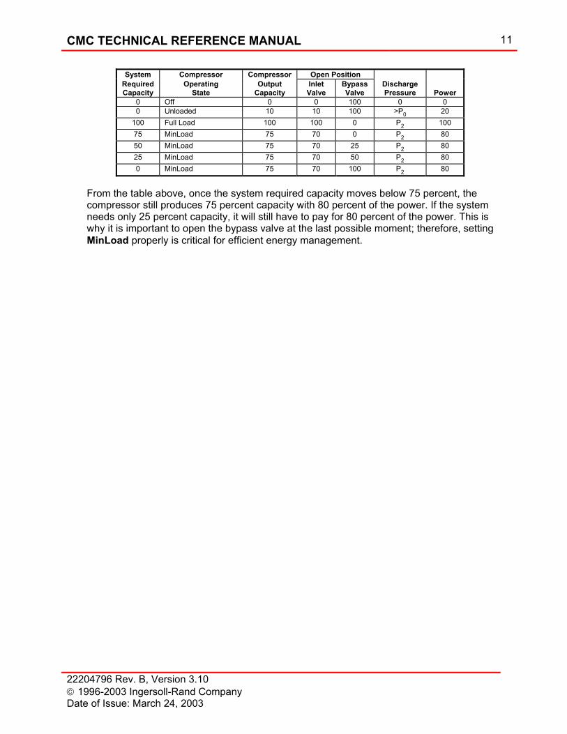
When ambient conditions produce the T=cold curve, the compressor will not be able to achieve the maximum capacity because it is beyond the MaxLoad value. Since MaxLoad is less than or equal to the motor nameplate FLA times the adjusted service factor, the maximum compressor capacity at T=cold could only be reached if the motor were sized for the T=cold condition. MinLoad Control Setpoint in units of amps (sometimes referred to as throttle limit TL) is the power value at which the CMC transfers modulation control from the inlet to the bypass valve (Figure 10). The reason for this transfer is to prevent the compressor from entering into a surge condition. The bypass valve vents air to the atmosphere and maintains the pressure setpoint by using the bypass valve pressure PID loop. At the same time, the inlet valve maintains the MinLoad setpoint by using the inlet valve MinLoad PID loop; therefore, once the MinLoad
setpoint is reached, the compressor continues to produce a constant amount of air. Part of this air goes to the Plant Air System, and the remainder is blown off. Even though the Plant Air System receives only a portion of the air produced, the amount of power remains constant. The following table presents seven capacity requirements for a plant air system. At each of the capacities, the table shows the compressor output, valve position, discharge pressure and power. Each of these values represents a percentage and is only an example. P2 is the specified discharge pressure and P0 is the barometric pressure.
Dis
char
ge P
ress
ure
Pow
er a
t Cou
plin
g
Capacity - Mass FlowM
inLo
ad
Max
Load
Thot
Tcold
Figure 9: MinLoad and MaxLoad
Figure 10: MinLoad
CMC TECHNICAL REFERENCE MANUAL 11
22204796 Rev. B, Version 3.10 1996-2003 Ingersoll-Rand Company Date of Issue: March 24, 2003
From the table above, once the system required capacity moves below 75 percent, the compressor still produces 75 percent capacity with 80 percent of the power. If the system needs only 25 percent capacity, it will still have to pay for 80 percent of the power. This is why it is important to open the bypass valve at the last possible moment; therefore, setting MinLoad properly is critical for efficient energy management.
System Compressor Compressor Open Position Required Capacity
Operating State
Output Capacity
Inlet Valve
Bypass Valve
Discharge Pressure
Power
0 Off 0 0 100 0 0 0 Unloaded 10 10 100 >P0 20
100 Full Load 100 100 0 P2 100 75 MinLoad 75 70 0 P2 80 50 MinLoad 75 70 25 P2 80 25 MinLoad 75 70 50 P2 80 0 MinLoad 75 70 100 P2 80
12 CMC TECHNICAL REFERENCE MANUAL
22204796 Rev. B, Version 3.10 1996-2003 Ingersoll-Rand Company
Date of Issue: March 24, 2003
MinLoadSetpoint
Capacity, scfm
Mot
or C
urre
nt, a
mps Natural
SurgePoints
Curve "marginally" affected bychanges in inlet temperature at a
constant inlet pressure
Amps vary with voltage
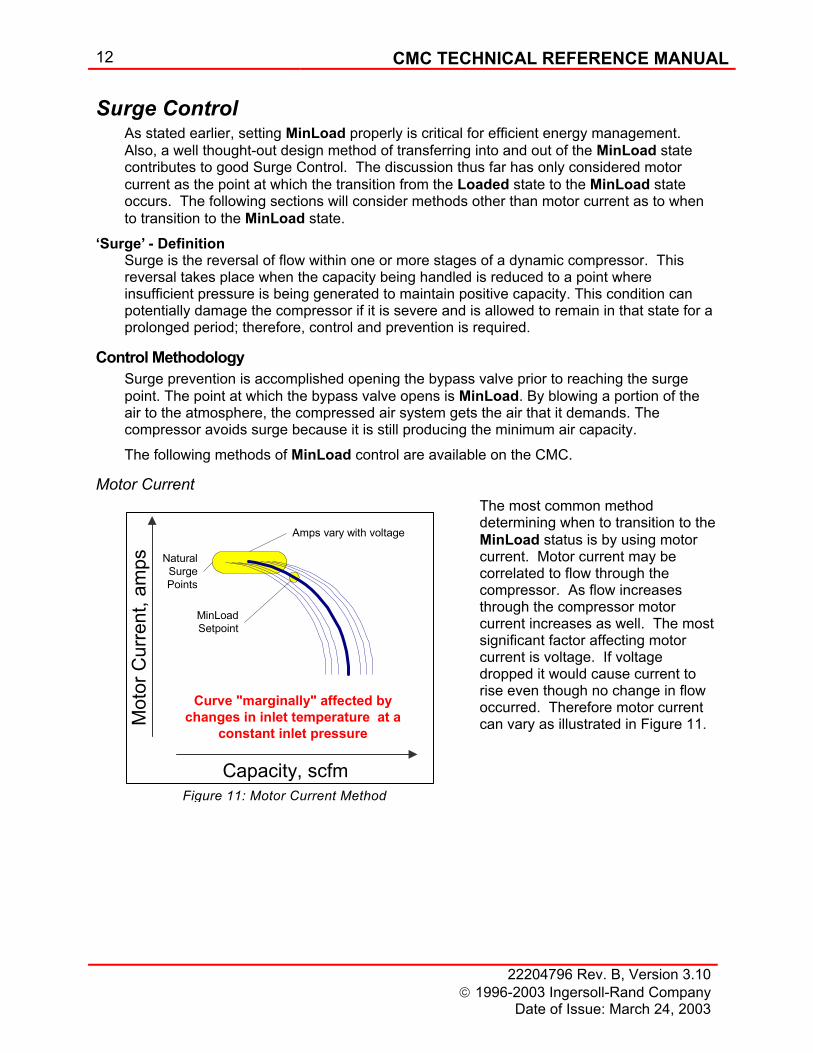
Surge Control As stated earlier, setting MinLoad properly is critical for efficient energy management. Also, a well thought-out design method of transferring into and out of the MinLoad state contributes to good Surge Control. The discussion thus far has only considered motor current as the point at which the transition from the Loaded state to the MinLoad state occurs. The following sections will consider methods other than motor current as to when to transition to the MinLoad state.
‘Surge’ - Definition Surge is the reversal of flow within one or more stages of a dynamic compressor. This reversal takes place when the capacity being handled is reduced to a point where insufficient pressure is being generated to maintain positive capacity. This condition can potentially damage the compressor if it is severe and is allowed to remain in that state for a prolonged period; therefore, control and prevention is required.
Control Methodology Surge prevention is accomplished opening the bypass valve prior to reaching the surge point. The point at which the bypass valve opens is MinLoad. By blowing a portion of the air to the atmosphere, the compressed air system gets the air that it demands. The compressor avoids surge because it is still producing the minimum air capacity.
The following methods of MinLoad control are available on the CMC.
Motor Current The most common method determining when to transition to the MinLoad status is by using motor current. Motor current may be correlated to flow through the compressor. As flow increases through the compressor motor current increases as well. The most significant factor affecting motor current is voltage. If voltage dropped it would cause current to rise even though no change in flow occurred. Therefore motor current can vary as illustrated in Figure 11.
Figure 11: Motor Current Method
CMC TECHNICAL REFERENCE MANUAL 13
22204796 Rev. B, Version 3.10 1996-2003 Ingersoll-Rand Company Date of Issue: March 24, 2003
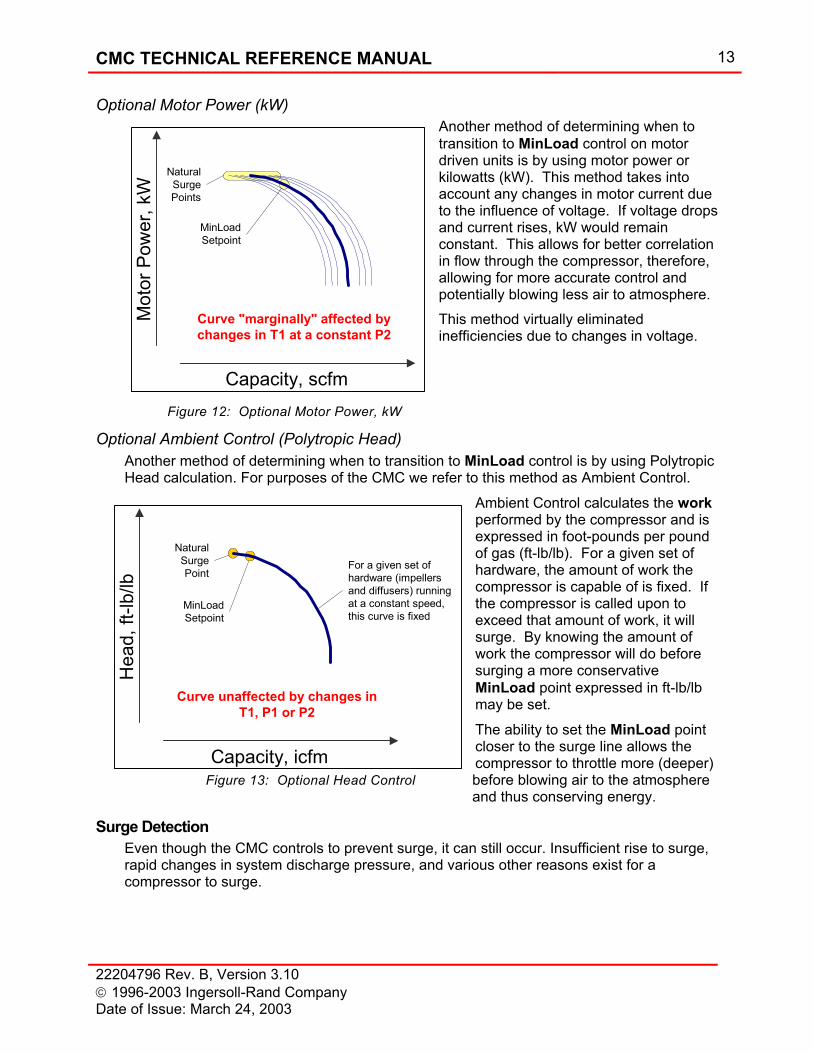
Optional Motor Power (kW) Another method of determining when to transition to MinLoad control on motor driven units is by using motor power or kilowatts (kW). This method takes into account any changes in motor current due to the influence of voltage. If voltage drops and current rises, kW would remain constant. This allows for better correlation in flow through the compressor, therefore, allowing for more accurate control and potentially blowing less air to atmosphere. This method virtually eliminated inefficiencies due to changes in voltage.
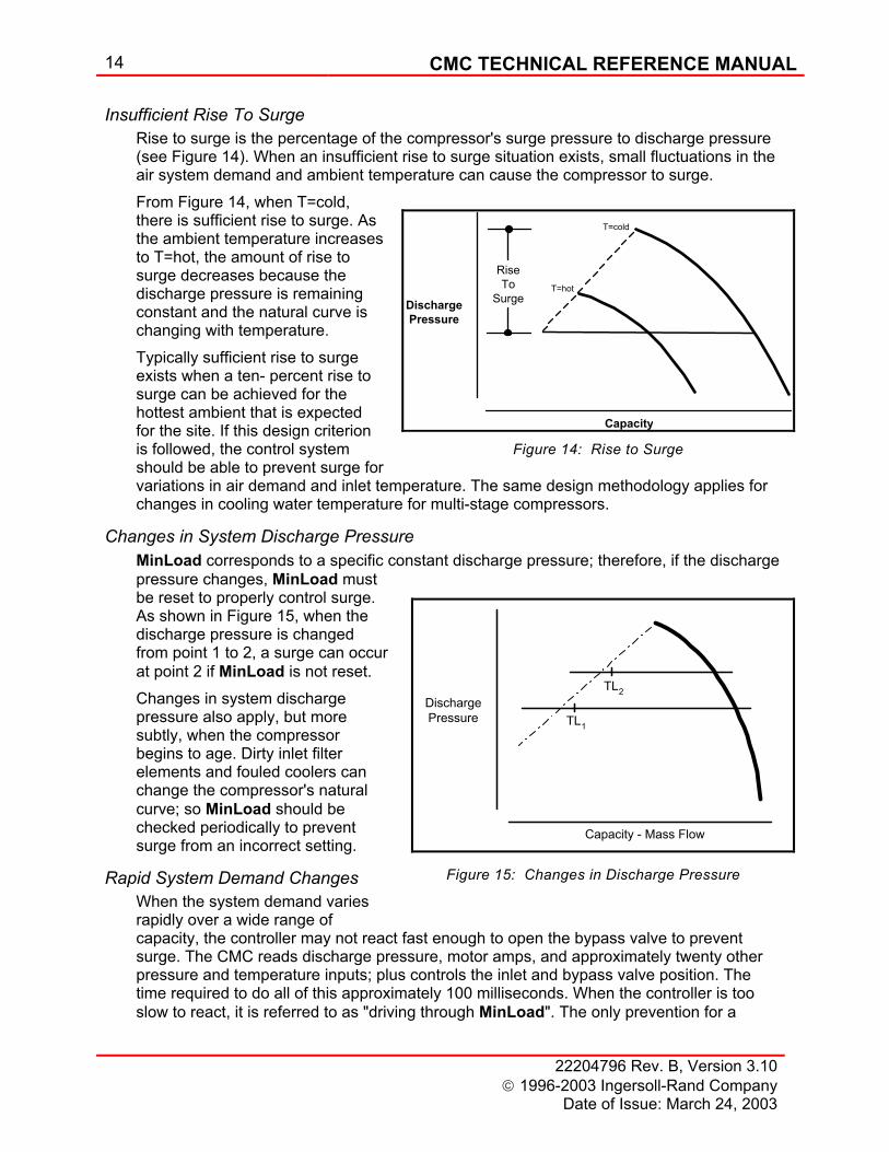
Optional Ambient Control (Polytropic Head) Another method of determining when to transition to MinLoad control is by using Polytropic Head calculation. For purposes of the CMC we refer to this method as Ambient Control.
Ambient Control calculates the work performed by the compressor and is expressed in foot-pounds per pound of gas (ft-lb/lb). For a given set of hardware, the amount of work the compressor is capable of is fixed. If the compressor is called upon to exceed that amount of work, it will surge. By knowing the amount of work the compressor will do before surging a more conservative MinLoad point expressed in ft-lb/lb may be set.
The ability to set the MinLoad point closer to the surge line allows the compressor to throttle more (deeper) before blowing air to the atmosphere and thus conserving energy.
Surge Detection Even though the CMC controls to prevent surge, it can still occur. Insufficient rise to surge, rapid changes in system discharge pressure, and various other reasons exist for a compressor to surge.
MinLoadSetpoint
Capacity, scfm
Mot
or P
ower
, kW
NaturalSurgePoints
Curve "marginally" affected bychanges in T1 at a constant P2
Figure 12: Optional Motor Power, kW
MinLoadSetpoint
Capacity, icfm
Hea
d, ft
-lb/lb
NaturalSurgePoint
For a given set ofhardware (impellersand diffusers) runningat a constant speed,this curve is fixed
Curve unaffected by changes inT1, P1 or P2
Figure 13: Optional Head Control
14 CMC TECHNICAL REFERENCE MANUAL
22204796 Rev. B, Version 3.10 1996-2003 Ingersoll-Rand Company
Date of Issue: March 24, 2003
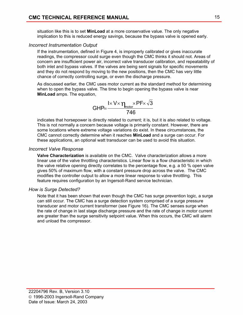
Insufficient Rise To Surge Rise to surge is the percentage of the compressor's surge pressure to discharge pressure (see Figure 14). When an insufficient rise to surge situation exists, small fluctuations in the air system demand and ambient temperature can cause the compressor to surge. From Figure 14, when T=cold, there is sufficient rise to surge. As the ambient temperature increases to T=hot, the amount of rise to surge decreases because the discharge pressure is remaining constant and the natural curve is changing with temperature. Typically sufficient rise to surge exists when a ten- percent rise to surge can be achieved for the hottest ambient that is expected for the site. If this design criterion is followed, the control system should be able to prevent surge for variations in air demand and inlet temperature. The same design methodology applies for changes in cooling water temperature for multi-stage compressors.
Changes in System Discharge Pressure MinLoad corresponds to a specific constant discharge pressure; therefore, if the discharge pressure changes, MinLoad must be reset to properly control surge. As shown in Figure 15, when the discharge pressure is changed from point 1 to 2, a surge can occur at point 2 if MinLoad is not reset. Changes in system discharge pressure also apply, but more subtly, when the compressor begins to age. Dirty inlet filter elements and fouled coolers can change the compressor's natural curve; so MinLoad should be checked periodically to prevent surge from an incorrect setting.
Rapid System Demand Changes When the system demand varies rapidly over a wide range of capacity, the controller may not react fast enough to open the bypass valve to prevent surge. The CMC reads discharge pressure, motor amps, and approximately twenty other pressure and temperature inputs; plus controls the inlet and bypass valve position. The time required to do all of this approximately 100 milliseconds. When the controller is too slow to react, it is referred to as "driving through MinLoad". The only prevention for a
Capacity
DischargePressure
RiseTo
Surge
T=cold
T=hot
Figure 14: Rise to Surge
Capacity - Mass Flow
DischargePressure TL1
TL2
Figure 15: Changes in Discharge Pressure
CMC TECHNICAL REFERENCE MANUAL 15
22204796 Rev. B, Version 3.10 1996-2003 Ingersoll-Rand Company Date of Issue: March 24, 2003
situation like this is to set MinLoad at a more conservative value. The only negative implication to this is reduced energy savings, because the bypass valve is opened early.
Incorrect Instrumentation Output If the instrumentation, defined in Figure 4, is improperly calibrated or gives inaccurate readings, the compressor could surge even though the CMC thinks it should not. Areas of concern are insufficient power air, incorrect valve transducer calibration, and repeatability of both inlet and bypass valves. If the valves are being sent signals for specific movements and they do not respond by moving to the new positions, then the CMC has very little chance of correctly controlling surge, or even the discharge pressure. As discussed earlier, the CMC uses motor current as the standard method for determining when to open the bypass valve. The time to begin opening the bypass valve is near MinLoad amps. The equation,
GHPI V PF
motor=× × × ×η 3
746
indicates that horsepower is directly related to current; it is, but it is also related to voltage. This is not normally a concern because voltage is primarily constant. However, there are some locations where extreme voltage variations do exist. In these circumstances, the CMC cannot correctly determine when it reaches MinLoad and a surge can occur. For these applications, an optional watt transducer can be used to avoid this situation.
Incorrect Valve Response Valve Characterization is available on the CMC. Valve characterization allows a more linear use of the valve throttling characteristics. Linear flow is a flow characteristic in which the valve relative opening directly correlates to the percentage flow, e.g. a 50 % open valve gives 50% of maximum flow, with a constant pressure drop across the valve. The CMC modifies the controller output to allow a more linear response to valve throttling. This feature requires configuration by an Ingersoll-Rand service technician.
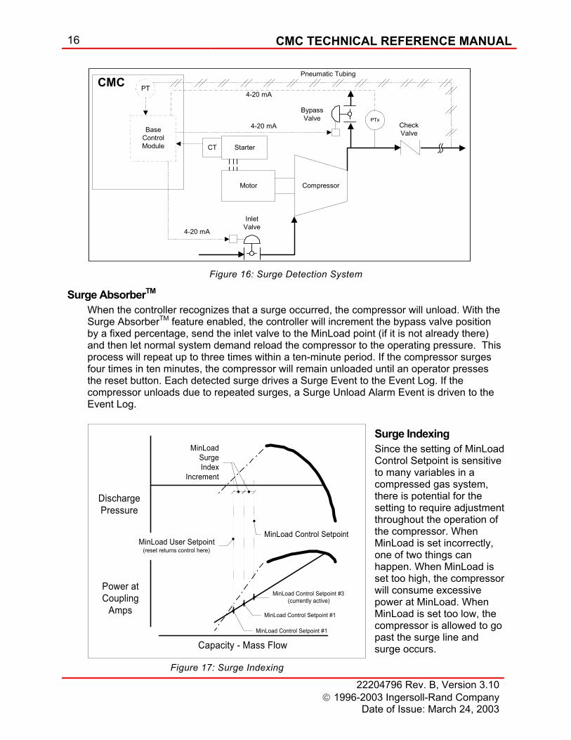
How is Surge Detected? Note that it has been shown that even though the CMC has surge prevention logic, a surge can still occur. The CMC has a surge detection system comprised of a surge pressure transducer and motor current transformer (see Figure 16). The CMC senses surge when the rate of change in last stage discharge pressure and the rate of change in motor current are greater than the surge sensitivity setpoint value. When this occurs, the CMC will alarm and unload the compressor.
16 CMC TECHNICAL REFERENCE MANUAL
22204796 Rev. B, Version 3.10 1996-2003 Ingersoll-Rand Company
Date of Issue: March 24, 2003
Capacity - Mass Flow
Power atCoupling
Amps
DischargePressure
MinLoad User Setpoint(reset returns control here)
MinLoadSurgeIndex
Increment
MinLoad Control Setpoint
MinLoad Control Setpoint #1
MinLoad Control Setpoint #1
MinLoad Control Setpoint #3(currently active)
CompressorMotor
StarterCT
BypassValve
InletValve
CheckValveBase
ControlModule
PT
4-20 mA
4-20 mA
CMCPneumatic Tubing
PTx
4-20 mA
Figure 16: Surge Detection System
Surge AbsorberTM When the controller recognizes that a surge occurred, the compressor will unload. With the Surge AbsorberTM feature enabled, the controller will increment the bypass valve position by a fixed percentage, send the inlet valve to the MinLoad point (if it is not already there) and then let normal system demand reload the compressor to the operating pressure. This process will repeat up to three times within a ten-minute period. If the compressor surges four times in ten minutes, the compressor will remain unloaded until an operator presses the reset button. Each detected surge drives a Surge Event to the Event Log. If the compressor unloads due to repeated surges, a Surge Unload Alarm Event is driven to the Event Log.
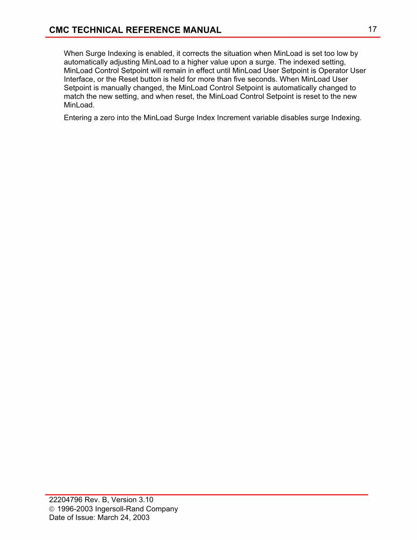
Surge Indexing Since the setting of MinLoad Control Setpoint is sensitive to many variables in a compressed gas system, there is potential for the setting to require adjustment throughout the operation of the compressor. When MinLoad is set incorrectly, one of two things can happen. When MinLoad is set too high, the compressor will consume excessive power at MinLoad. When MinLoad is set too low, the compressor is allowed to go past the surge line and surge occurs.
Figure 17: Surge Indexing
CMC TECHNICAL REFERENCE MANUAL 17
22204796 Rev. B, Version 3.10 1996-2003 Ingersoll-Rand Company Date of Issue: March 24, 2003
When Surge Indexing is enabled, it corrects the situation when MinLoad is set too low by automatically adjusting MinLoad to a higher value upon a surge. The indexed setting, MinLoad Control Setpoint will remain in effect until MinLoad User Setpoint is Operator User Interface, or the Reset button is held for more than five seconds. When MinLoad User Setpoint is manually changed, the MinLoad Control Setpoint is automatically changed to match the new setting, and when reset, the MinLoad Control Setpoint is reset to the new MinLoad. Entering a zero into the MinLoad Surge Index Increment variable disables surge Indexing.
18 CMC TECHNICAL REFERENCE MANUAL
22204796 Rev. B, Version 3.10 1996-2003 Ingersoll-Rand Company
Date of Issue: March 24, 2003
Oil System Control The CMC panel provides control of the prelube pump and lube oil heater in the starting sequence, during normal operation and after compressor stops or trips.
Prelube Pump The prelube pump is started when the panel power is on and seal air is present. The prelube pump stops after the compressor start button is pushed and the programmable timer “Start Time” has expired. The pump does not come on again until the Stop key is pressed, and will remain on until the panel power is turned off or Seal Air is lost.
Oil Heater The oil heater is thermostatically controlled. When the oil temperature is below the set point temperature, the oil heater is energized, above the set point temperature it is de-energized. The oil heater control does not have any interaction with the microprocessor board and is designed to operate with the control panel de-energized as long as three-phase power is available.
CMC TECHNICAL REFERENCE MANUAL 19
22204796 Rev. B, Version 3.10 1996-2003 Ingersoll-Rand Company Date of Issue: March 24, 2003
Protection and Monitoring Each CMC base module has twenty-three analog inputs, sixteen digital inputs, four analog outputs and sixteen digital outputs for control, protection and monitoring. These input functions provide the CMC with information about the compressor. The CMC board uses the output functions to communicate to the user and perform actions like starting the compressor and turning on the prelube pump. All of these inputs and outputs are required to interface physical actions to and from the electronics.
Analog Functions An analog function is one in which an electrical signal represents a specific pressure, temperature, vibration and current input; or valve position output. As these inputs and outputs fluctuate, the electrical signal to and from the microprocessor board also fluctuates proportionally to the amount of change.
Analog Inputs Twenty-one grounded and two floating analog inputs are used for protection, monitoring and control. Each input used for protecting the compressor can be programmed for alarm and trip indication. Each of these functions is pre-programmed with the function title, engineering units, range, alarm and trip values, so no configuration is required upon receipt by the customer. The CMC uses pressure transmitters to measure pressure, resistance temperature detectors (RTD) and transmitters to measure temperature, eddy current based vibration transmitters to measure shaft vibration and a current transformer to measure the motor current. The CMC logic used for the protective alarm and trip functions is as follows: if the actual value of the input is greater than or equal to the alarm or trip value, indicate the condition. This logic is used for all inputs except, low oil pressure and low oil temperature where the logic is reversed. To prevent nuisance alarms and trips, all standard analog inputs use an alternate alarm and trip value during the stopped, starting, and coasting states. The alternate setpoints cannot be edited through the Operator User Interface.
Analog Outputs Two of the available four analog output functions are for inlet and bypass valve positioning. These are only output functions. The standard configuration for a CMC has no input information as to the valve location. The CMC calculates the position based upon where the valves are supposed to be and sends those signals to the valves.
Digital Functions A digital function is one in which the presence of an electrical signal indicates ON or YES, and the lack of that signal represents OFF or NO. This is analogous to a light switch that has only two states, ON or OFF. The term "discrete" is also used instead of digital in many instances. The term that will be used throughout this documentation shall be digital.
Digital Inputs The sixteen digital inputs provide status of field switches. Emergency Stop and Low Seal Air Pressure trip are standard. Any of these inputs can be configured as an alarm or trip. All inputs operate on 24 VDC power.

20 CMC TECHNICAL REFERENCE MANUAL
22204796 Rev. B, Version 3.10 1996-2003 Ingersoll-Rand Company
Date of Issue: March 24, 2003
Digital Outputs The sixteen digital outputs are used by the CMC to start the prelube pump, energize the main starter contacts, indicate that an alarm or trip condition exists, indicate that the compressor is unloaded, activate the running unloaded shutdown timer and to sound the horn. Outputs can operate on 120 VAC, 60 Hz, single-phase power or 24 VDC power.
CMC TECHNICAL REFERENCE MANUAL 21
22204796 Rev. B, Version 3.10 1996-2003 Ingersoll-Rand Company Date of Issue: March 24, 2003
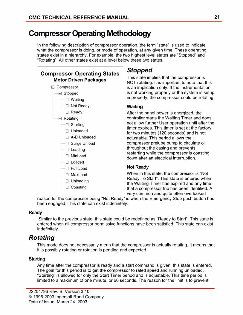
Compressor Operating StatesMotor Driven Packages
Stopped+
WaitingNot ReadyReady
Compressor+
+ RotatingStarting
Loading
Unloaded
MinLoadLoadedFull LoadMaxLoad
A-D UnloadedSurge Unload
UnloadingCoasting
Compressor Operating Methodology In the following description of compressor operation, the term “state” is used to indicate what the compressor is doing, or mode of operation, at any given time. These operating states exist in a hierarchy. For example, the two highest level states are “Stopped” and “Rotating”. All other states exist at a level below these two states.
Stopped This state implies that the compressor is NOT rotating. It is important to note that this is an implication only. If the instrumentation is not working properly or the system is setup improperly, the compressor could be rotating.
Waiting After the panel power is energized, the controller starts the Waiting Timer and does not allow further User operation until after the timer expires. This timer is set at the factory for two minutes (120 seconds) and is not adjustable. This period allows the compressor prelube pump to circulate oil throughout the casing and prevents restarting while the compressor is coasting down after an electrical interruption.
Not Ready When in this state, the compressor is “Not Ready To Start”. This state is entered when the Waiting Timer has expired and any time that a compressor trip has been identified. A very common and quite often overlooked
reason for the compressor being “Not Ready” is when the Emergency Stop push button has been engaged. This state can exist indefinitely.
Ready Similar to the previous state, this state could be redefined as “Ready to Start”. This state is entered when all compressor permissive functions have been satisfied. This state can exist indefinitely.
Rotating This mode does not necessarily mean that the compressor is actually rotating. It means that it is possibly rotating or rotation is pending and expected.
Starting Any time after the compressor is ready and a start command is given, this state is entered. The goal for this period is to get the compressor to rated speed and running unloaded. “Starting” is allowed for only the Start Timer period and is adjustable. This time period is limited to a maximum of one minute, or 60 seconds. The reason for the limit is to prevent
22 CMC TECHNICAL REFERENCE MANUAL
22204796 Rev. B, Version 3.10 1996-2003 Ingersoll-Rand Company
Date of Issue: March 24, 2003
the compressor from operating in the critical speed for an extended period. Stage vibration alarm and trip setpoints are increased during this period to get the compressor through the critical speed region. After the compressor has “Started”, the alarm and trip setpoints are adjusted back to their original values. The same procedure occurs for stage air temperature also.
This state exits only after the Starting Timer has expired. THE COMPRESSOR IS ALWAYS STARTED UNLOADED. On exit of “Starting”, the compressor will return to the mode that it was in the last time it ran. For example, typical operation implies that prior to stopping the compressor, the Unload key is pressed. If this occurred, then the compressor will remain in “Unload” after starting. If the compressor was running and tripped, the compressor will automatically return to the “Loaded” mode on exit of the Starting state. The User may also press the Load or Unload key prior to pressing the Start key to force the compressor to into either post-Starting state.
Unloaded The compressor is in this state after a start (and Load Selected is not in effect) or when the User issues an unload command. A-D Unloaded and Surge Unload are also considered states. However, these two states are really just reasons for being in the Unloaded state. A-D Unloaded means “AutoDual Unloaded” which occurs when AutoDual is enabled and the system pressure has been high enough for a long enough time to drive an unload command. “Surge Unload” is similar in that a surge event drives the unload command instead of AutoDual. These states can exist indefinitely.
Loading When a valid load command is issued, the compressor will enter this state. This state exists until the MinLoad state is satisfied. The duration of this state depends upon PID settings for the inlet valve at the MinLoad state and the demand for air.
MinLoad, Loaded, Full Load and MaxLoad These states transition among themselves as demand for air changes. “MinLoad” means that the bypass valve is controlling pressure and the inlet valve is maintaining the MinLoad Control Setpoint. “Loaded” means that the inlet valve is controlling pressure and the bypass valve is closed. “Full Load” occurs when the inlet valve has reached the full open or 100% position. “MaxLoad” means that the inlet valve is maintaining the MaxLoad Setpoint to prevent motor damage. In both the “Full Load” and “MaxLoad” states, system pressure may be lower than setpoint pressure.
Unloading This state occurs when a valid Unload command is issued and will persist until the compressor reaches the Unloaded state.
Coasting When a trip or any stop command is issued and the compressor is running, the motor will be de-energized and the compressor will begin to coast to a Stopped state. This state will remain as long as the adjustable Coast Timer is in effect. At the end of the timer, the compressor will enter either the Ready or Not Ready state.
CMC TECHNICAL REFERENCE MANUAL 23
22204796 Rev. B, Version 3.10 1996-2003 Ingersoll-Rand Company Date of Issue: March 24, 2003
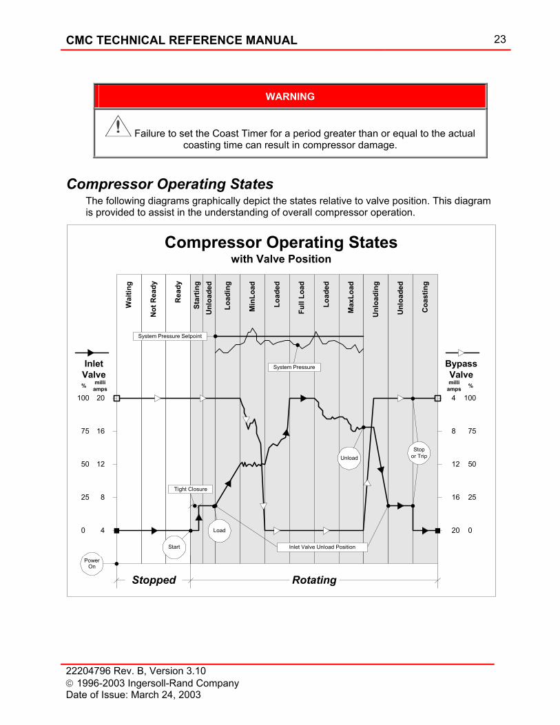
WARNING
Failure to set the Coast Timer for a period greater than or equal to the actual coasting time can result in compressor damage.
Compressor Operating States The following diagrams graphically depict the states relative to valve position. This diagram is provided to assist in the understanding of overall compressor operation.
Unl
oade
d
Coa
stin
g
Star
ting
Load
ing
Load
ed
Min
Load
Full
Load
Load
ed
Max
Load
Unl
oadi
ng
Unl
oade
d20
Compressor Operating Stateswith Valve Position
RotatingStopped
4
16
12
8
100
0
75
50
25
Not
Rea
dy
Rea
dy
Wai
ting
Start
100
0
25
20
4
8
12
16
BypassValve
50
75
milliamps %
PowerOn
InletValve
milliamps%
Tight Closure
Inlet Valve Unload Position
Load
Unload
System Pressure Setpoint
System Pressure
Stopor Trip
24 CMC TECHNICAL REFERENCE MANUAL
22204796 Rev. B, Version 3.10 1996-2003 Ingersoll-Rand Company
Date of Issue: March 24, 2003
User Interface
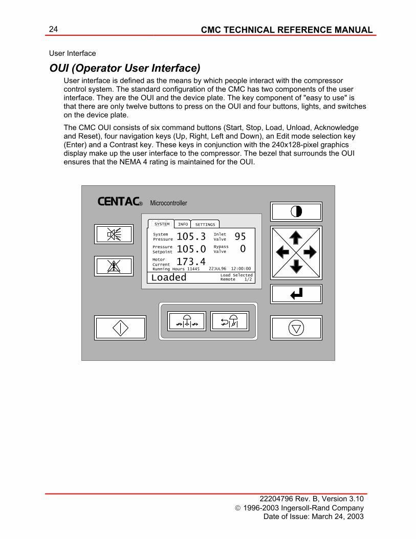
OUI (Operator User Interface) User interface is defined as the means by which people interact with the compressor control system. The standard configuration of the CMC has two components of the user interface. They are the OUI and the device plate. The key component of "easy to use" is that there are only twelve buttons to press on the OUI and four buttons, lights, and switches on the device plate. The CMC OUI consists of six command buttons (Start, Stop, Load, Unload, Acknowledge and Reset), four navigation keys (Up, Right, Left and Down), an Edit mode selection key (Enter) and a Contrast key. These keys in conjunction with the 240x128-pixel graphics display make up the user interface to the compressor. The bezel that surrounds the OUI ensures that the NEMA 4 rating is maintained for the OUI.
CENTAC Microcontroller
1/2
SETTINGSINFO
MotorCurrent
SystemPressure
PressureSetpoint
105.3
105.0
173.4
Loaded
InletValve
BypassValve
95
0
RemoteLoad Selected
22JUL96 12:00:00
SYSTEM
Running Hours 11445
CMC TECHNICAL REFERENCE MANUAL 25
22204796 Rev. B, Version 3.10 1996-2003 Ingersoll-Rand Company Date of Issue: March 24, 2003
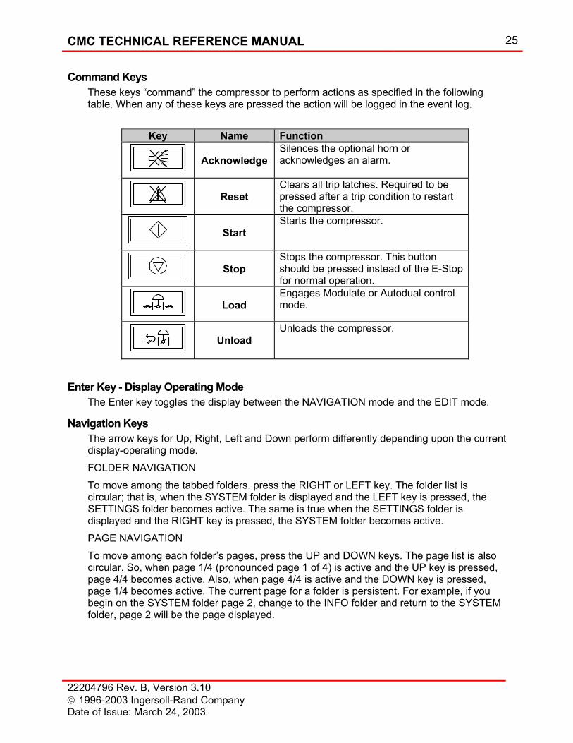
Command Keys These keys “command” the compressor to perform actions as specified in the following table. When any of these keys are pressed the action will be logged in the event log.
Enter Key - Display Operating Mode The Enter key toggles the display between the NAVIGATION mode and the EDIT mode.
Navigation Keys The arrow keys for Up, Right, Left and Down perform differently depending upon the current display-operating mode. FOLDER NAVIGATION To move among the tabbed folders, press the RIGHT or LEFT key. The folder list is circular; that is, when the SYSTEM folder is displayed and the LEFT key is pressed, the SETTINGS folder becomes active. The same is true when the SETTINGS folder is displayed and the RIGHT key is pressed, the SYSTEM folder becomes active. PAGE NAVIGATION To move among each folder’s pages, press the UP and DOWN keys. The page list is also circular. So, when page 1/4 (pronounced page 1 of 4) is active and the UP key is pressed, page 4/4 becomes active. Also, when page 4/4 is active and the DOWN key is pressed, page 1/4 becomes active. The current page for a folder is persistent. For example, if you begin on the SYSTEM folder page 2, change to the INFO folder and return to the SYSTEM folder, page 2 will be the page displayed.
Key Name Function
Acknowledge
Silences the optional horn or acknowledges an alarm.
Reset
Clears all trip latches. Required to be pressed after a trip condition to restart the compressor.
Start
Starts the compressor.
Stop
Stops the compressor. This button should be pressed instead of the E-Stop for normal operation.
Load
Engages Modulate or Autodual control mode.
Unload
Unloads the compressor.
26 CMC TECHNICAL REFERENCE MANUAL
22204796 Rev. B, Version 3.10 1996-2003 Ingersoll-Rand Company
Date of Issue: March 24, 2003
Contrast Key This key changes the contrast of the backlight for the graphic LCD display. Pressing this key steps among each of the thirty two contrast levels. When stepped to the thirty second level, pressing the key again returns to the first contrast level.
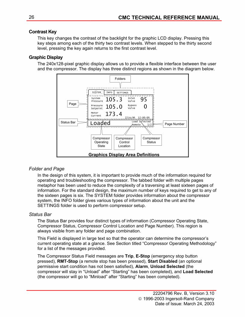
Graphic Display The 240x128-pixel graphic display allows us to provide a flexible interface between the user and the compressor. The display has three distinct regions as shown in the diagram below.
Folder and Page In the design of this system, it is important to provide much of the information required for operating and troubleshooting the compressor. The tabbed folder with multiple pages metaphor has been used to reduce the complexity of a traversing at least sixteen pages of information. For the standard design, the maximum number of keys required to get to any of the sixteen pages is six. The SYSTEM folder provides information about the compressor system, the INFO folder gives various types of information about the unit and the SETTINGS folder is used to perform compressor setup.
Status Bar The Status Bar provides four distinct types of information (Compressor Operating State, Compressor Status, Compressor Control Location and Page Number). This region is always visible from any folder and page combination. This Field is displayed in large text so that the operator can determine the compressor’s current operating state at a glance. See Section titled “Compressor Operating Methodology” for a list of the messages provided.
The Compressor Status Field messages are Trip, E-Stop (emergency stop button pressed), RMT-Stop (a remote stop has been pressed), Start Disabled (an optional permissive start condition has not been satisfied), Alarm, Unload Selected (the compressor will stay in “Unload” after “Starting” has been completed), and Load Selected (the compressor will go to “Minload” after “Starting” has been completed).
1/2
SETTINGSINFOSYSTEM
MotorCurrent
SystemPressure
PressureSetpoint
105.3
105.0
173.4
Loaded
InletValve
BypassValve
95
0
Remote
Load Selected
22JUL96 12:00:00
Page
Status Bar Page Number
CompressorControl
Location
CompressorOperating
State
Folders
CompressorStatus
Graphics Display Area Definitions
CMC TECHNICAL REFERENCE MANUAL 27
22204796 Rev. B, Version 3.10 1996-2003 Ingersoll-Rand Company Date of Issue: March 24, 2003
The Compressor Control Location Field messages are Local, Remote (remote hardwired commands i.e. start, stop, load, unload etc.), Network (MODBUS, DF1 or ASC communication with a UCM) and Remote/Net (both Remote and Network). This indication is provided to indicate to the operator that a remote location is in control of the compressor and the compressor may start, stop, load, unload, etc. without the local operator initiating any commands. These three fields combine to provide the operator with the necessary information to create a cursory determination of the status of the compressor. When a more thorough determination is required, the operator can get additional detail by looking through the other pages in the system. The Page Number indicates the current page for the current folder with the number of pages in the folder. The number of pages is given so that the user always knows where he is in the system.
Navigation Mode Navigation mode is active when a folder name (SYSTEM, INFO or SETTINGS) is highlighted.
Edit (Setpoint Changes) Mode Edit mode is activated by pressing the ENTER key. In Edit mode one can change Setpoints for a page. Once in this mode, the highlight will move from around the folder name to the item to be changed. Use the Right and Left arrow keys to move among the changeable items and the Up and Down arrow keys to change the value of the item. When changes are complete, press the Enter key again to return to Navigation mode.
Scroll Mode Scroll mode is activated by pressing the ENTER key when a folder name INFO is highlighted and the Event Log or the Routine Start / Stop page is visible. The Scroll mode is used to page through the event log. To move among the pages, press the UP or DOWN keys. To deactivate the Scroll mode, press the Enter key.

28 CMC TECHNICAL REFERENCE MANUAL
22204796 Rev. B, Version 3.10 1996-2003 Ingersoll-Rand Company
Date of Issue: March 24, 2003
Pop-up Message In the event of an Alarm or Trip, a pop-up message will appear providing the customer with the phone number of the local Ingersoll-Rand representative. If the event is a Trip, the event log on the SYSTEM folder will be displayed with the pop-up message centered over the displayed page. The message may be removed by pressing the ENTER key. The following are examples of the pop-up message in the event of an Alarm or Trip.
2/3
SYSTEM SETTINGSINFO
Not Ready RemoteTrip
Event Name Time Date
1 Low Oil Pressure Trip 09:18:44 0720 2 Low Oil Pressure Alarm 09:18:43 0720 3 Reset key pressed 09:18:34 0720 4 Low Oil Pressure Trip 09:08:43 0720 5 Low Oil Pressure Alarm 08:58:23 0720 6 Load key pressed 08:24:01 0720 7 Start key pressed 08:23:12 0720
Trip Example
For Parts or ServicePlease Call:
39 02 950 56499
Press ENTER key to continue
1/4
SETTINGSINFOSYSTEM
MotorCurrent
SystemPressure
PressureSetpoint
105.1105.0323.4
Loaded
InletValve
BypassValve
1000
RemoteLoad Selected
31-AUG-1999 12:00:00Running Hrs: 11445
Alarm Example
For Parts or ServicePlease Call:
39 02 950 56499
Press ENTER key to continue
CMC TECHNICAL REFERENCE MANUAL 29
22204796 Rev. B, Version 3.10 1996-2003 Ingersoll-Rand Company Date of Issue: March 24, 2003
INFO FolderSYSTEM Folder SETTINGS Folder
Navigation andEnter Keys
3/6
SYSTEM SETTINGSINFO
Loaded RemoteLoad Selected
Power On Hours 12338Running Hours 11445Loaded Hours 11223
BCM Ver: 2.51
Number of Starts 35
4/4
SETTINGSINFOSYSTEM
Digital Outputs
Loaded RemoteLoad Selected
Prelube Pump RunningCR1Remote Trouble
3/4
SETTINGSINFOSYSTEM
Digital Inputs
Loaded RemoteLoad Selected
Starter FeedbackE-Stop PressedLow Seal Air
2/4
SETTINGSINFOSYSTEM
Pressure Temperature Vibration
Loaded RemoteLoad Selected
Stage 1 30.1 95.8 0.25Stage 2 106.6 93.5 0.22
Oil 18.8 115.3Water 80.1
1/4
SETTINGSINFOSYSTEM
MotorCurrent
SystemPressure
PressureSetpoint
105.1105.0323.4
Loaded
InletValve
BypassValve
1000
RemoteLoad Selected
31-AUG-1999 12:00:00Running Hrs: 11445
1/6
SYSTEM SETTINGSINFO
Loaded RemoteLoad Selected
START LOAD UNLOAD
RESET
HORN SILENCECONTRAST
LEFT
UP
RIGHT
DOWN
ENTER
STOP
1/6
SYSTEM SETTINGSINFO
Loaded RemoteLoad Selected
Password * * * *
Setpoint Changes Enabled
English degF mils amps psi
Language and Units
Date, yyyy/mm/dd 1999/08/31
Time, hh:mm:ss 12:30:00
English degC mils amps kg/cm2
2/6
SYSTEM SETTINGSINFO
Loaded RemoteLoad Selected
MaxLoad (HLL) 400.0
User Setpoint (TL) 100.0
Surge Index Increment 1.0 Control Setpoint 100.0
Surge Absorber EnabledSurge Sensitivity 9.0
MinLoad
6/6
SYSTEM SETTINGSINFO
Loaded RemoteLoad Selected
Alarm Trip
Stage 1 Temperature 120 125Stage 1 Vibration 0.80 1.00
Stage 2 Temperature 120 125Stage 2 Vibration 0.75 0.95
Oil Pressure 18 16High Oil Temperature 120 125
Low Oil Temperature 100 95
4/6
SYSTEM SETTINGSINFO
Loaded RemoteLoad Selected
Modulate Autodual Reload Pressure, % of Setpoint 98 Unload Point, BV % Open 1 Unload Delay Time, seconds 1
ManualControl Mode
5/6
SYSTEM SETTINGSINFO
Loaded RemoteLoad Selected
Starting Timer, seconds 20
CT Ratio 60Inlet Unload Position, % 15Setpoint Ramp Rate, pressure/scan 5.0
Coasting Timer, seconds 240
3/6
SYSTEM
Loaded RemoteLoad Selected
PB IT D
Pressure 10.00 0.50 0.00
Pressure 10.00 0.50 0.00
MinLoad (TL) 25.00 0.50 0.00 MaxLoad (HLL) 99.99 0.50 0.00
SETTINGSINFO
Inlet Valve
Bypass Valve
rep/sec sec
2/6
SYSTEM SETTINGSINFO
Not Ready RemoteTrip
Event Name Time Date
1 Low Oil Pressure Trip 09:18:44 0720 2 Low Oil Pressure Alarm 09:18:43 0720 3 Reset key pressed 09:18:34 0720 4 Low Oil Pressure Trip 09:08:43 0720 5 Low Oil Pressure Alarm 08:58:23 0720 6 Load key pressed 08:24:01 0720 7 Start key pressed 08:23:12 0720
4/6
SYSTEM SETTINGSINFO
Ready RemoteLoad Selected
For parts or service contact your local Ingersoll-Rand representative at the following number:
39 02 950 56499
5/6
SYSTEM SETTINGSINFO
Ready RemoteLoad Selected
R E P L A C E M E N T P A R T S Part No. Description
6/6
SYSTEM SETTINGSINFO
Ready RemoteLoad Selected
R O U T I N E S T A R T / S T O P
Prior to starting, the operator shouldbecome familiar with the operation ofthe main driver. Refer to the drivermanufacturer's instructions in theOperation Manual. The operator shouldalso be familiar with all the accessoryand optional equipment contained on the
12345678 Inlet Filter Element Primary 12345678 Inlet Filter Element Secondary 12345678 Oil Filter 12345678 Demister Element 12345678 Lubricant, 55 gallon drum 12345678 Lubricant, 5 gallon drum
30 CMC TECHNICAL REFERENCE MANUAL
22204796 Rev. B, Version 3.10 1996-2003 Ingersoll-Rand Company
Date of Issue: March 24, 2003
1/4
SETTINGSINFOSYSTEM
MotorCurrent
SystemPressure
PressureSetpoint
105.1105.0323.4
Loaded
InletValve
BypassValve
1000
RemoteLoad Selected
31-AUG-1999 12:00:00Running Hours: 11445
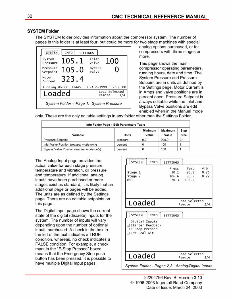
System Folder – Page 1: System Pressure
2/4
SETTINGSINFOSYSTEM
Press Temp Vib
Loaded RemoteLoad Selected
Stage 1 30.1 95.8 0.25Stage 2 106.6 93.5 0.22Oil 20.3 105.5
3/4
SETTINGSINFOSYSTEM
Digital Inputs
Loaded RemoteLoad Selected
Starter FeedbackE-Stop PressedLow Seal Air
System Folder - Pages 2,3: Analog/Digital Inputs
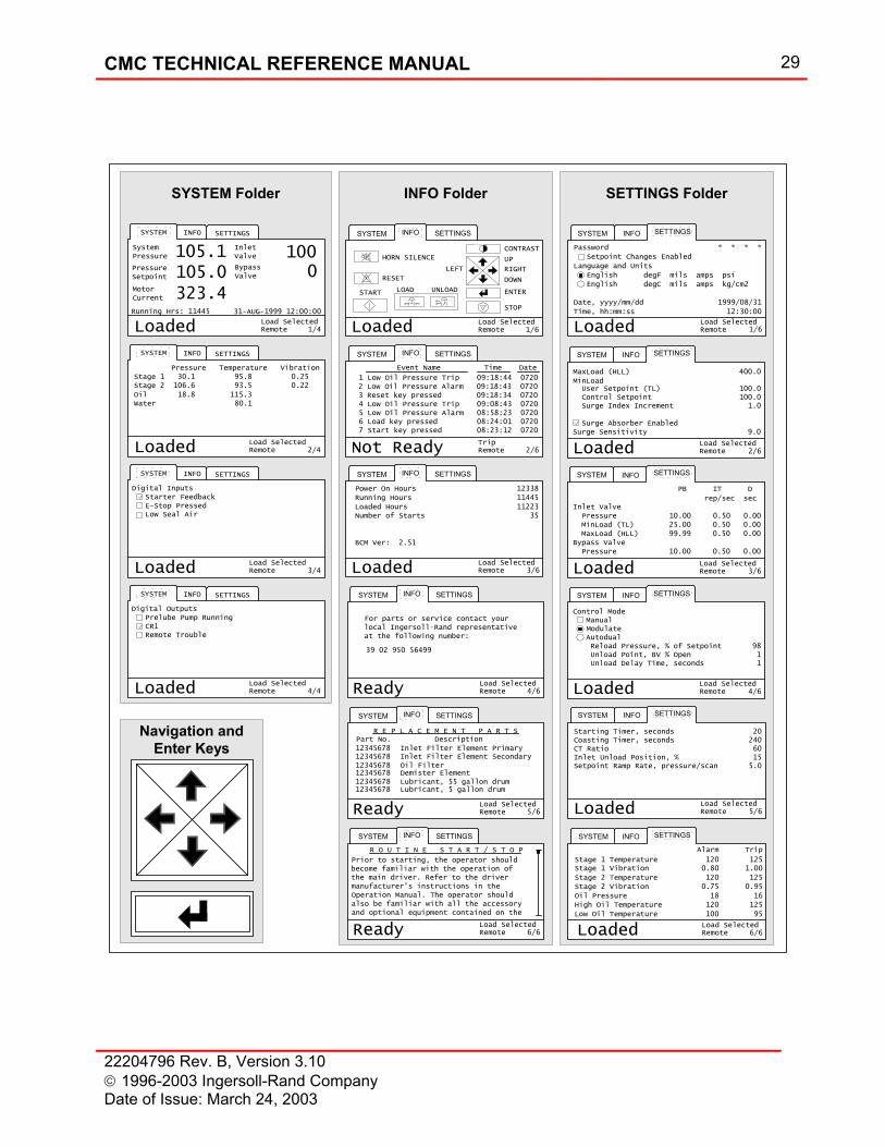
SYSTEM Folder The SYSTEM folder provides information about the compressor system. The number of pages in this folder is at least four; but could be more for two stage machines with special
analog options purchased, or for compressors with three stages or more. This page shows the main compressor operating parameters, running hours, date and time. The System Pressure and Pressure Setpoint are in units as defined by the Settings page, Motor Current is in Amps and valve positions are in percent open. Pressure Setpoint is always editable while the Inlet and Bypass Valve positions are edit enabled when in the Manual mode
only. These are the only editable settings in any folder other than the Settings Folder.
Info Folder Page 1 Edit Parameters Table
Variable
Units
Minimum Value
Maximum Value
Step Size
Pressure Setpoint pressure 0.0 999.9 0.1 Inlet Valve Position (manual mode only) percent 0 100 1 Bypass Valve Position (manual mode only) percent 0 100 1
The Analog Input page provides the actual value for each stage pressure, temperature and vibration, oil pressure and temperature. If additional analog inputs have been purchased or more stages exist as standard, it is likely that an additional page or pages will be added. The units are as defined by the Settings page. There are no editable setpoints on this page. The Digital Input page shows the current state of the digital (discrete) inputs for the system. The number of inputs will vary depending upon the number of optional inputs purchased. A check in the box to the left of the text indicates a TRUE condition, whereas, no check indicates a FALSE condition. For example, a check mark in the “E-Stop Pressed” boxed means that the Emergency Stop push button has been pressed. It is possible to have multiple Digital Input pages.
CMC TECHNICAL REFERENCE MANUAL 31
22204796 Rev. B, Version 3.10 1996-2003 Ingersoll-Rand Company Date of Issue: March 24, 2003
4/4
SETTINGSINFOSYSTEM
Digital Outputs
Loaded RemoteLoad Selected
Prelube Pump RunningCR1Remote Trouble
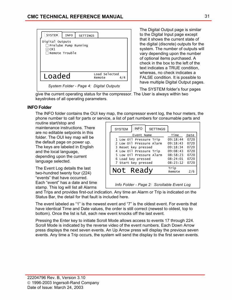
System Folder - Page 4: Digital Outputs
2/6
SYSTEM SETTINGSINFO
Not Ready RemoteTrip
Event Name Time Date
1 Low Oil Pressure Trip 09:18:44 0720 2 Low Oil Pressure Alarm 09:18:43 0720 3 Reset key pressed 09:18:34 0720 4 Low Oil Pressure Trip 09:08:43 0720 5 Low Oil Pressure Alarm 08:58:23 0720 6 Load key pressed 08:24:01 0720 7 Start key pressed 08:23:12 0720
Info Folder - Page 2: Scrollable Event Log
The Digital Output page is similar to the Digital Input page except that it shows the current state of the digital (discrete) outputs for the system. The number of outputs will vary depending upon the number of optional items purchased. A check in the box to the left of the text indicates a TRUE condition, whereas, no check indicates a FALSE condition. It is possible to have multiple Digital Output pages. The SYSTEM folder’s four pages
give the current operating status for the compressor. The User is always within two keystrokes of all operating parameters.
INFO Folder The INFO folder contains the OUI key map, the compressor event log, the hour meters, the phone number to call for parts or service, a list of part numbers for consumable parts and routine start/stop and maintenance instructions. There are no editable setpoints in this folder. The OUI key map will be the default page on power up. The keys are labeled in English and the local language, depending upon the current language selected. The Event Log details the last two-hundred twenty four (224) “events” that have occurred. Each “event” has a date and time stamp. This log will list all Alarms and Trips and provides first-out indication. Any time an Alarm or Trip is indicated on the Status Bar, the detail for that fault is included here. The event labeled as “1” is the newest event and “7” is the oldest event. For events that have identical Time and Date values, the order is still correct (newest to oldest, top to bottom). Once the list is full, each new event knocks off the last event. Pressing the Enter key to initiate Scroll Mode allows access to events 17 through 224. Scroll Mode is indicated by the reverse video of the event numbers. Each Down Arrow press displays the next seven events. An Up Arrow press will display the previous seven events. Any time a Trip occurs, the system will send the display to the first seven events.
32 CMC TECHNICAL REFERENCE MANUAL
22204796 Rev. B, Version 3.10 1996-2003 Ingersoll-Rand Company
Date of Issue: March 24, 2003
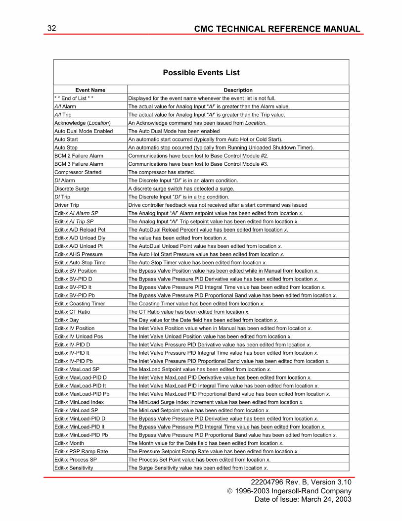
Possible Events List
Event Name Description
* * End of List * * Displayed for the event name whenever the event list is not full. A/I Alarm The actual value for Analog Input “AI” is greater than the Alarm value. A/I Trip The actual value for Analog Input “AI” is greater than the Trip value. Acknowledge (Location) An Acknowledge command has been issued from Location. Auto Dual Mode Enabled The Auto Dual Mode has been enabled Auto Start An automatic start occurred (typically from Auto Hot or Cold Start). Auto Stop An automatic stop occurred (typically from Running Unloaded Shutdown Timer). BCM 2 Failure Alarm Communications have been lost to Base Control Module #2. BCM 3 Failure Alarm Communications have been lost to Base Control Module #3. Compressor Started The compressor has started. DI Alarm The Discrete Input “DI” is in an alarm condition. Discrete Surge A discrete surge switch has detected a surge. DI Trip The Discrete Input “DI” is in a trip condition. Driver Trip Drive controller feedback was not received after a start command was issued Edit-x AI Alarm SP The Analog Input “AI” Alarm setpoint value has been edited from location x. Edit-x AI Trip SP The Analog Input “AI” Trip setpoint value has been edited from location x. Edit-x A/D Reload Pct The AutoDual Reload Percent value has been edited from location x. Edit-x A/D Unload Dly The value has been edited from location x. Edit-x A/D Unload Pt The AutoDual Unload Point value has been edited from location x. Edit-x AHS Pressure The Auto Hot Start Pressure value has been edited from location x. Edit-x Auto Stop Time The Auto Stop Timer value has been edited from location x. Edit-x BV Position The Bypass Valve Position value has been edited while in Manual from location x. Edit-x BV-PID D The Bypass Valve Pressure PID Derivative value has been edited from location x. Edit-x BV-PID It The Bypass Valve Pressure PID Integral Time value has been edited from location x. Edit-x BV-PID Pb The Bypass Valve Pressure PID Proportional Band value has been edited from location x. Edit-x Coasting Timer The Coasting Timer value has been edited from location x. Edit-x CT Ratio The CT Ratio value has been edited from location x. Edit-x Day The Day value for the Date field has been edited from location x. Edit-x IV Position The Inlet Valve Position value when in Manual has been edited from location x. Edit-x IV Unload Pos The Inlet Valve Unload Position value has been edited from location x. Edit-x IV-PID D The Inlet Valve Pressure PID Derivative value has been edited from location x. Edit-x IV-PID It The Inlet Valve Pressure PID Integral Time value has been edited from location x. Edit-x IV-PID Pb The Inlet Valve Pressure PID Proportional Band value has been edited from location x. Edit-x MaxLoad SP The MaxLoad Setpoint value has been edited from location x. Edit-x MaxLoad-PID D The Inlet Valve MaxLoad PID Derivative value has been edited from location x. Edit-x MaxLoad-PID It The Inlet Valve MaxLoad PID Integral Time value has been edited from location x. Edit-x MaxLoad-PID Pb The Inlet Valve MaxLoad PID Proportional Band value has been edited from location x. Edit-x MinLoad Index The MinLoad Surge Index Increment value has been edited from location x. Edit-x MinLoad SP The MinLoad Setpoint value has been edited from location x. Edit-x MinLoad-PID D The Bypass Valve Pressure PID Derivative value has been edited from location x. Edit-x MinLoad-PID It The Bypass Valve Pressure PID Integral Time value has been edited from location x. Edit-x MinLoad-PID Pb The Bypass Valve Pressure PID Proportional Band value has been edited from location x. Edit-x Month The Month value for the Date field has been edited from location x. Edit-x PSP Ramp Rate The Pressure Setpoint Ramp Rate value has been edited from location x. Edit-x Process SP The Process Set Point value has been edited from location x. Edit-x Sensitivity The Surge Sensitivity value has been edited from location x.
CMC TECHNICAL REFERENCE MANUAL 33
22204796 Rev. B, Version 3.10 1996-2003 Ingersoll-Rand Company Date of Issue: March 24, 2003
3/6
SYSTEM SETTINGSINFO
Loaded RemoteLoad Selected
Power On Hours 12338Running Hours 11445Loaded Hours 11223
BCM Ver: 3.00
Number of Starts 35
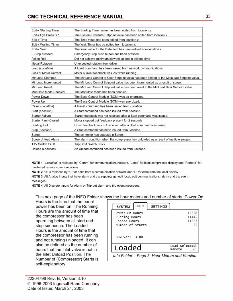
Info Folder – Page 3: Hour Meters and Version
Edit-x Starting Timer The Starting Timer value has been edited from location x. Edit-x Sys Press SP The System Pressure Setpoint value has been edited from location x. Edit-x Time The Time value has been edited from location x. Edit-x Waiting Timer The Wait Timer has be edited from location x. Edit-x Year The Year value for the Date field has been edited from location x. E-Stop pressed Emergency Stop push button has been pressed. Fail to Roll Did not achieve minimum slow roll speed in allotted time Illegal Rotation Unexpected rotation from driver Load (Location) A Load command has been issued from network communications. Loss of Motor Current Motor current feedback was lost while running. MinLoad Clamped The MinLoad Control or User Setpoint value has been limited to the MaxLoad Setpoint value. MinLoad Incremented The MinLoad Control Setpoint value has been incremented as a result of surge. MinLoad Reset The MinLoad Control Setpoint value has been reset to the MinLoad User Setpoint value. Modulate Mode Enabled The Modulate Mode has been enabled. Power Down The Base Control Module (BCM) was de-energized. Power Up The Base Control Module (BCM) was energized. Reset (Location) A Reset command has been issued from Location. Start (Location) A Start command has been issued from Location. Starter Failure Starter feedback was not received after a Start command was issued. Starter Fault-Closed Motor stopped but feedback present for 2 seconds Starting Fail Driver feedback was not received after a Start command was issued. Stop (Location) A Stop command has been issued from Location. Surge The controller has detected a Surge. Surge Unload Alarm The alarm condition when the compressor has unloaded as a result of multiple surges. TTV Switch Fault Trip Limit Switch Stuck Unload (Location) An Unload command has been issued from Location. NOTE 1: “Location” is replaced by “Comm” for communications network, “Local” for local compressor display and “Remote” for hardwired remote communications. NOTE 2: “x” is replaced by “C” for edits from a communication network and “L” for edits from the local display. NOTE 3: All Analog Inputs that have alarm and trip sepoints get edit local, edit communications, alarm and trip event messages. NOTE 4: All Discrete Inputs for Alarm or Trip get alarm and trip event messages.
This next page of the INFO Folder shows the hour meters and number of starts. Power On Hours is the time that the panel power has been on. The Running Hours are the amount of time that the compressor has been operating between all start and stop sequence. The Loaded Hours is the amount of time that the compressor has been running and not running unloaded. It can also be defined as the number of hours that the inlet valve is not in the Inlet Unload Position. The Number of (Compressor) Starts is self-explanatory.
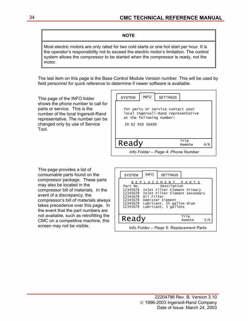
34 CMC TECHNICAL REFERENCE MANUAL
22204796 Rev. B, Version 3.10 1996-2003 Ingersoll-Rand Company
Date of Issue: March 24, 2003
4/6
SYSTEM SETTINGSINFO
Ready RemoteTrip
For parts or service contact your local Ingersoll-Rand representative at the following number:
39 02 950 56499
Info Folder – Page 5: Replacement Parts
NOTE
Most electric motors are only rated for two cold starts or one hot start per hour. It is the operator’s responsibility not to exceed the electric motor’s limitation. The control system allows the compressor to be started when the compressor is ready, not the motor.
The last item on this page is the Base Control Module Version number. This will be used by field personnel for quick reference to determine if newer software is available. This page of the INFO folder shows the phone number to call for parts or service. This is the number of the local Ingersoll-Rand representative. The number can be changed only by use of Service Tool.
This page provides a list of consumable parts found on the compressor package. These parts may also be located in the compressor bill of materials. In the event of a discrepancy, the compressor’s bill of materials always takes precedence over this page. In the event that the part numbers are not available, such as retrofitting the CMC on a competitive machine, this screen may not be visible.
5/6
SYSTEM SETTINGSINFO
Ready RemoteTrip
R E P L A C E M E N T P A R T S Part No. Description 12345678 12345678 Inlet Filter Element Secondary 12345678 Oil Filter 12345678 Demister Element 12345678 Lubricant, 55 gallon drum 12345678 Lubricant, 5 gallons
Inlet Filter Element Primary
Info Folder – Page 4: Phone Number
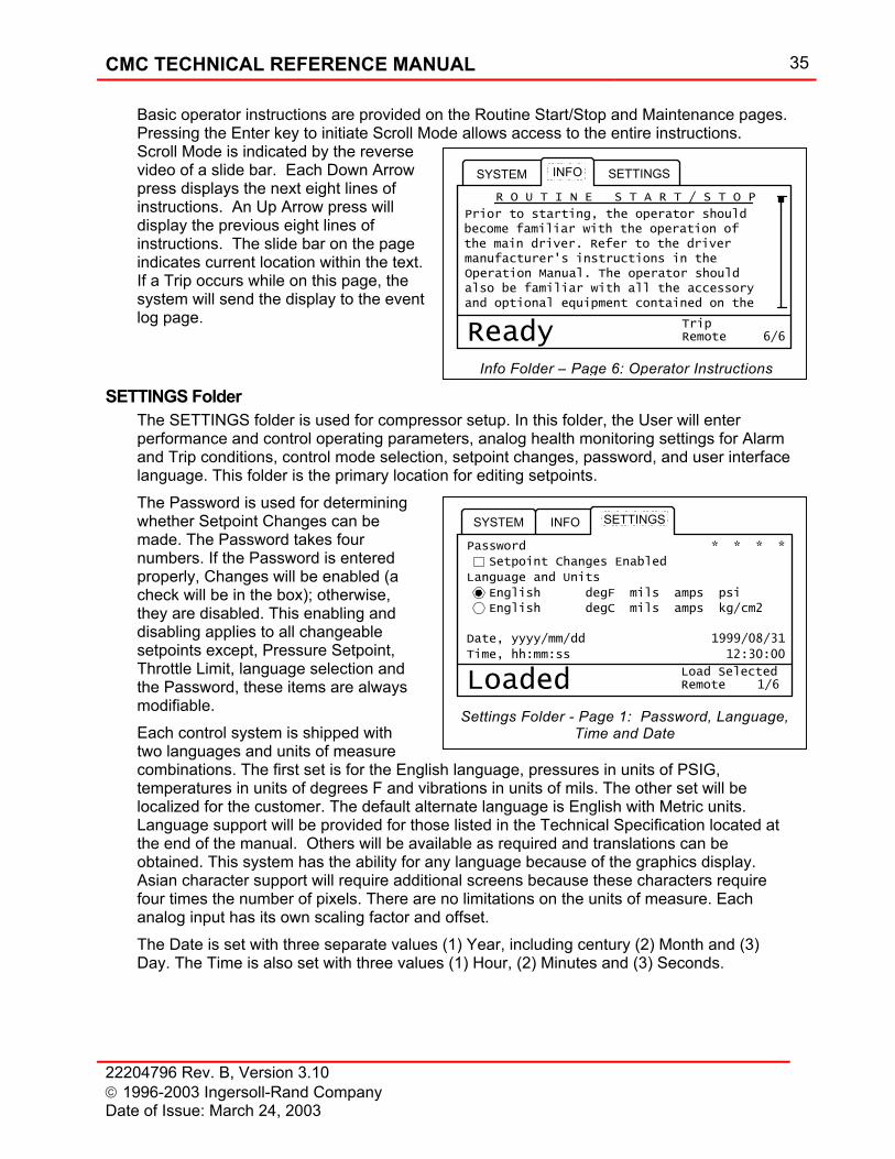
CMC TECHNICAL REFERENCE MANUAL 35
22204796 Rev. B, Version 3.10 1996-2003 Ingersoll-Rand Company Date of Issue: March 24, 2003
1/6
SYSTEM SETTINGSINFO
Loaded RemoteLoad Selected
Password * * * *
Setpoint Changes Enabled
English degF mils amps psi
Language and Units
Date, yyyy/mm/dd 1999/08/31
Time, hh:mm:ss 12:30:00
English degC mils amps kg/cm2
Settings Folder - Page 1: Password, Language, Time and Date
Basic operator instructions are provided on the Routine Start/Stop and Maintenance pages. Pressing the Enter key to initiate Scroll Mode allows access to the entire instructions. Scroll Mode is indicated by the reverse video of a slide bar. Each Down Arrow press displays the next eight lines of instructions. An Up Arrow press will display the previous eight lines of instructions. The slide bar on the page indicates current location within the text. If a Trip occurs while on this page, the system will send the display to the event log page.
SETTINGS Folder The SETTINGS folder is used for compressor setup. In this folder, the User will enter performance and control operating parameters, analog health monitoring settings for Alarm and Trip conditions, control mode selection, setpoint changes, password, and user interface language. This folder is the primary location for editing setpoints. The Password is used for determining whether Setpoint Changes can be made. The Password takes four numbers. If the Password is entered properly, Changes will be enabled (a check will be in the box); otherwise, they are disabled. This enabling and disabling applies to all changeable setpoints except, Pressure Setpoint, Throttle Limit, language selection and the Password, these items are always modifiable. Each control system is shipped with two languages and units of measure combinations. The first set is for the English language, pressures in units of PSIG, temperatures in units of degrees F and vibrations in units of mils. The other set will be localized for the customer. The default alternate language is English with Metric units. Language support will be provided for those listed in the Technical Specification located at the end of the manual. Others will be available as required and translations can be obtained. This system has the ability for any language because of the graphics display. Asian character support will require additional screens because these characters require four times the number of pixels. There are no limitations on the units of measure. Each analog input has its own scaling factor and offset. The Date is set with three separate values (1) Year, including century (2) Month and (3) Day. The Time is also set with three values (1) Hour, (2) Minutes and (3) Seconds.
6/6
SYSTEM SETTINGSINFO
Ready RemoteTrip
R O U T I N E S T A R T / S T O P
Prior to starting, the operator shouldbecome familiar with the operation ofthe main driver. Refer to the drivermanufacturer's instructions in theOperation Manual. The operator shouldalso be familiar with all the accessoryand optional equipment contained on the
Info Folder – Page 6: Operator Instructions
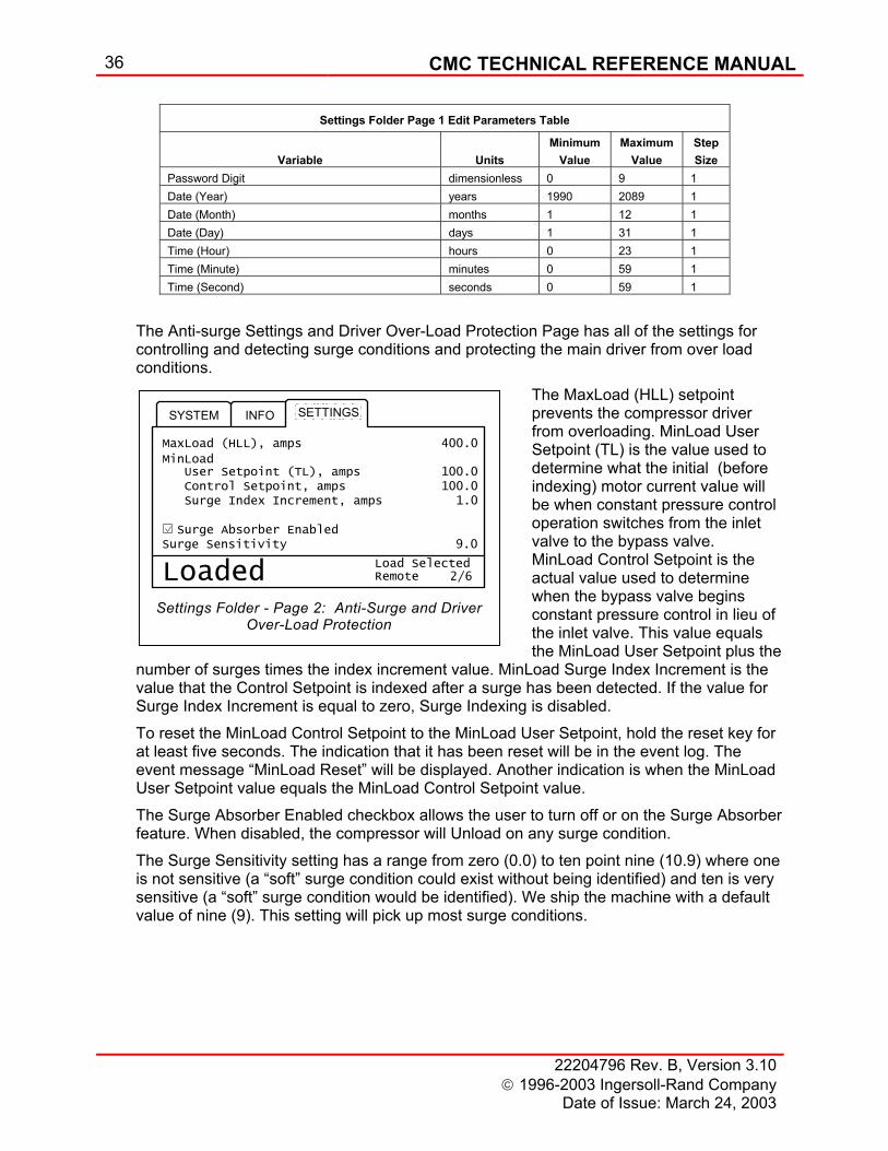
36 CMC TECHNICAL REFERENCE MANUAL
22204796 Rev. B, Version 3.10 1996-2003 Ingersoll-Rand Company
Date of Issue: March 24, 2003
2/6
SYSTEM SETTINGSINFO
Loaded RemoteLoad Selected
MaxLoad (HLL), amps 400.0
User Setpoint (TL), amps 100.0
Surge Index Increment, amps 1.0 Control Setpoint, amps 100.0
Surge Absorber EnabledSurge Sensitivity 9.0
MinLoad
Settings Folder - Page 2: Anti-Surge and Driver Over-Load Protection
Settings Folder Page 1 Edit Parameters Table
Variable
Units
Minimum Value
Maximum Value
Step Size
Password Digit dimensionless 0 9 1 Date (Year) years 1990 2089 1 Date (Month) months 1 12 1 Date (Day) days 1 31 1 Time (Hour) hours 0 23 1 Time (Minute) minutes 0 59 1 Time (Second) seconds 0 59 1
The Anti-surge Settings and Driver Over-Load Protection Page has all of the settings for controlling and detecting surge conditions and protecting the main driver from over load conditions.
The MaxLoad (HLL) setpoint prevents the compressor driver from overloading. MinLoad User Setpoint (TL) is the value used to determine what the initial (before indexing) motor current value will be when constant pressure control operation switches from the inlet valve to the bypass valve. MinLoad Control Setpoint is the actual value used to determine when the bypass valve begins constant pressure control in lieu of the inlet valve. This value equals the MinLoad User Setpoint plus the
number of surges times the index increment value. MinLoad Surge Index Increment is the value that the Control Setpoint is indexed after a surge has been detected. If the value for Surge Index Increment is equal to zero, Surge Indexing is disabled. To reset the MinLoad Control Setpoint to the MinLoad User Setpoint, hold the reset key for at least five seconds. The indication that it has been reset will be in the event log. The event message “MinLoad Reset” will be displayed. Another indication is when the MinLoad User Setpoint value equals the MinLoad Control Setpoint value. The Surge Absorber Enabled checkbox allows the user to turn off or on the Surge Absorber feature. When disabled, the compressor will Unload on any surge condition. The Surge Sensitivity setting has a range from zero (0.0) to ten point nine (10.9) where one is not sensitive (a “soft” surge condition could exist without being identified) and ten is very sensitive (a “soft” surge condition would be identified). We ship the machine with a default value of nine (9). This setting will pick up most surge conditions.
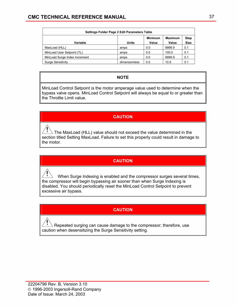
CMC TECHNICAL REFERENCE MANUAL 37
22204796 Rev. B, Version 3.10 1996-2003 Ingersoll-Rand Company Date of Issue: March 24, 2003
Settings Folder Page 2 Edit Parameters Table
Variable
Units
Minimum Value
Maximum Value
Step Size
MaxLoad (HLL) amps 0.0 9999.9 0.1 MinLoad User Setpoint (TL) amps 0.0 100.0 0.1 MinLoad Surge Index Increment amps 0.0 9999.9 0.1 Surge Sensitivity dimensionless 0.0 10.9 0.1
NOTE
MinLoad Control Setpoint is the motor amperage value used to determine when the bypass valve opens. MinLoad Control Setpoint will always be equal to or greater than the Throttle Limit value.
CAUTION
The MaxLoad (HLL) value should not exceed the value determined in the section titled Setting MaxLoad. Failure to set this properly could result in damage to the motor.
CAUTION
When Surge Indexing is enabled and the compressor surges several times, the compressor will begin bypassing air sooner than when Surge Indexing is disabled. You should periodically reset the MinLoad Control Setpoint to prevent excessive air bypass.
CAUTION
Repeated surging can cause damage to the compressor; therefore, use caution when desensitizing the Surge Sensitivity setting.
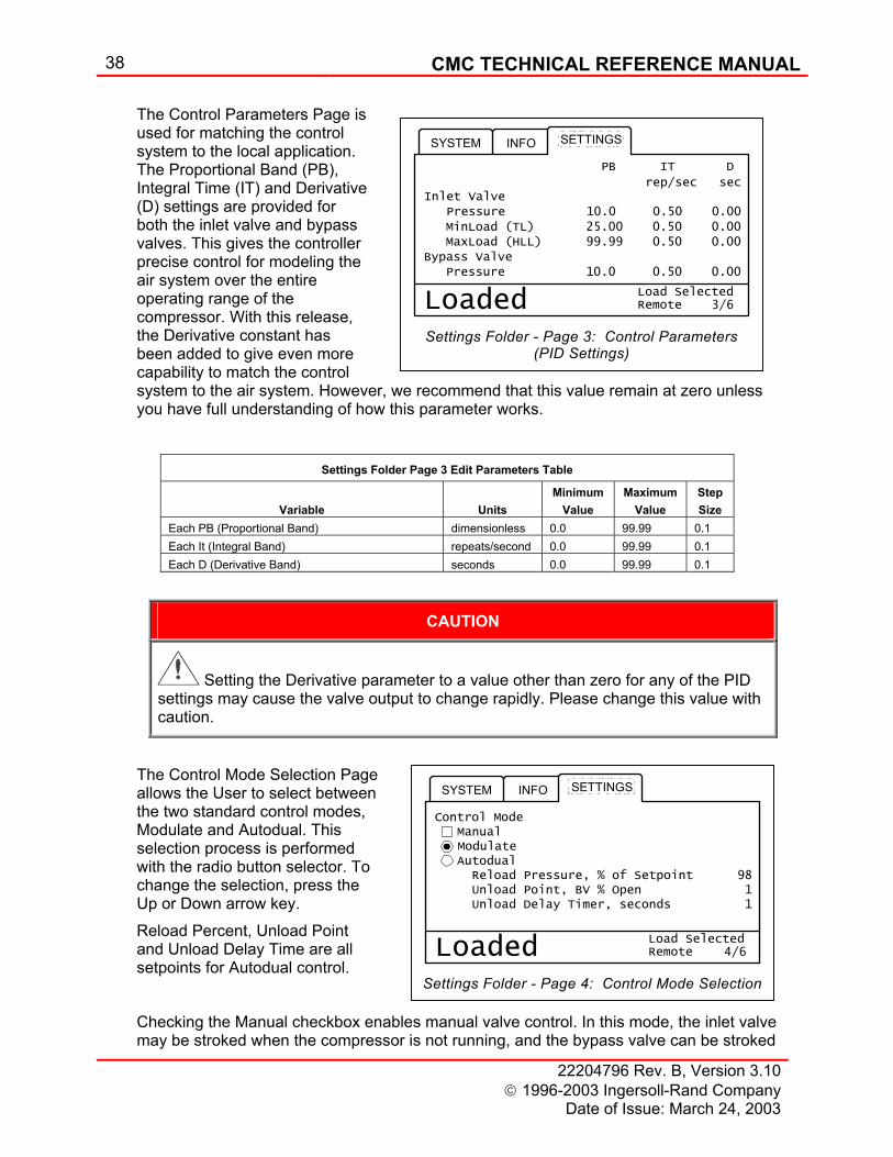
38 CMC TECHNICAL REFERENCE MANUAL
22204796 Rev. B, Version 3.10 1996-2003 Ingersoll-Rand Company
Date of Issue: March 24, 2003
3/6
SYSTEM
Loaded RemoteLoad Selected
PB IT D
Pressure 10.0 0.50 0.00
Pressure 10.0 0.50 0.00
MinLoad (TL) 25.00 0.50 0.00 MaxLoad (HLL) 99.99 0.50 0.00
SETTINGSINFO
Inlet Valve
Bypass Valve
rep/sec sec
Settings Folder - Page 3: Control Parameters (PID Settings)
4/6
SYSTEM SETTINGSINFO
Loaded RemoteLoad Selected
Modulate Autodual Reload Pressure, % of Setpoint 98 Unload Point, BV % Open 1 Unload Delay Timer, seconds 1
ManualControl Mode
Settings Folder - Page 4: Control Mode Selection
The Control Parameters Page is used for matching the control system to the local application. The Proportional Band (PB), Integral Time (IT) and Derivative (D) settings are provided for both the inlet valve and bypass valves. This gives the controller precise control for modeling the air system over the entire operating range of the compressor. With this release, the Derivative constant has been added to give even more capability to match the control system to the air system. However, we recommend that this value remain at zero unless you have full understanding of how this parameter works.
Settings Folder Page 3 Edit Parameters Table
Variable
Units
Minimum Value
Maximum Value
Step Size
Each PB (Proportional Band) dimensionless 0.0 99.99 0.1 Each It (Integral Band) repeats/second 0.0 99.99 0.1 Each D (Derivative Band) seconds 0.0 99.99 0.1
CAUTION
Setting the Derivative parameter to a value other than zero for any of the PID settings may cause the valve output to change rapidly. Please change this value with caution.
The Control Mode Selection Page allows the User to select between the two standard control modes, Modulate and Autodual. This selection process is performed with the radio button selector. To change the selection, press the Up or Down arrow key. Reload Percent, Unload Point and Unload Delay Time are all setpoints for Autodual control. Checking the Manual checkbox enables manual valve control. In this mode, the inlet valve may be stroked when the compressor is not running, and the bypass valve can be stroked
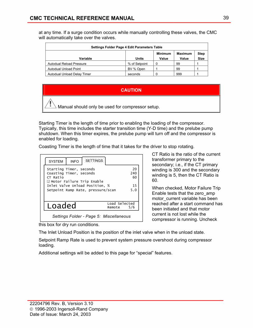
CMC TECHNICAL REFERENCE MANUAL 39
22204796 Rev. B, Version 3.10 1996-2003 Ingersoll-Rand Company Date of Issue: March 24, 2003
5/6
SYSTEM SETTINGSINFO
Loaded RemoteLoad Selected
Starting Timer, seconds 20
CT Ratio 60 Motor Failure Trip Enable
Coasting Timer, seconds 240
Setpoint Ramp Rate, pressure/scan 5.0
Inlet Valve Unload Position, % 15
Settings Folder - Page 5: Miscellaneous
at any time. If a surge condition occurs while manually controlling these valves, the CMC will automatically take over the valves.
Settings Folder Page 4 Edit Parameters Table
Variable
Units
Minimum Value
Maximum Value
Step Size
Autodual Reload Pressure % of Setpoint 0 99 1 Autodual Unload Point BV % Open 1 99 1 Autodual Unload Delay Timer seconds 0 999 1
CAUTION
Manual should only be used for compressor setup.
Starting Timer is the length of time prior to enabling the loading of the compressor. Typically, this time includes the starter transition time (Y-D time) and the prelube pump shutdown. When this timer expires, the prelube pump will turn off and the compressor is enabled for loading. Coasting Timer is the length of time that it takes for the driver to stop rotating.
CT Ratio is the ratio of the current transformer primary to the secondary; i.e., if the CT primary winding is 300 and the secondary winding is 5, then the CT Ratio is 60. When checked, Motor Failure Trip Enable tests that the zero_amp motor_current variable has been reached after a start command has been initiated and that motor current is not lost while the compressor is running. Uncheck
this box for dry run conditions. The Inlet Unload Position is the position of the inlet valve when in the unload state. Setpoint Ramp Rate is used to prevent system pressure overshoot during compressor loading. Additional settings will be added to this page for “special” features.
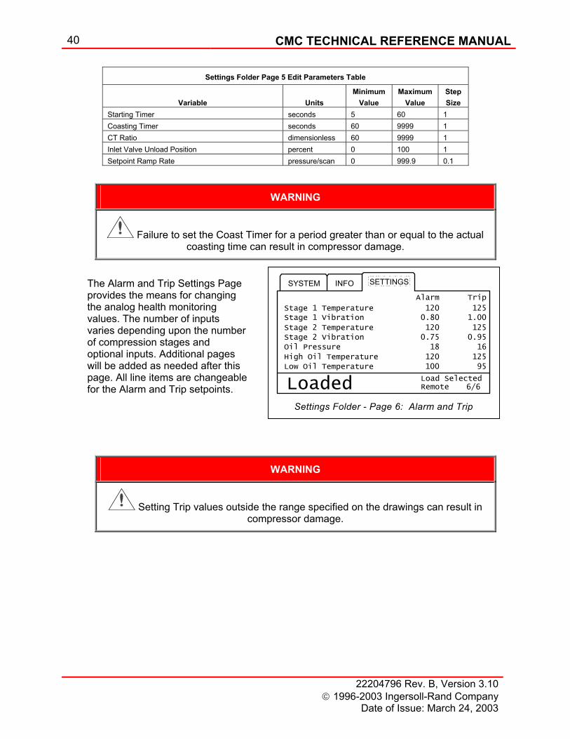
40 CMC TECHNICAL REFERENCE MANUAL
22204796 Rev. B, Version 3.10 1996-2003 Ingersoll-Rand Company
Date of Issue: March 24, 2003
6/6
SYSTEM SETTINGSINFO
Loaded RemoteLoad Selected
Alarm Trip
Stage 1 Temperature 120 125Stage 1 Vibration 0.80 1.00
Stage 2 Temperature 120 125Stage 2 Vibration 0.75 0.95Oil Pressure 18 16
High Oil Temperature 120 125Low Oil Temperature 100 95
Settings Folder - Page 6: Alarm and Trip
Settings Folder Page 5 Edit Parameters Table
Variable
Units
Minimum Value
Maximum Value
Step Size
Starting Timer seconds 5 60 1 Coasting Timer seconds 60 9999 1 CT Ratio dimensionless 60 9999 1 Inlet Valve Unload Position percent 0 100 1 Setpoint Ramp Rate pressure/scan 0 999.9 0.1
WARNING
Failure to set the Coast Timer for a period greater than or equal to the actual coasting time can result in compressor damage.
The Alarm and Trip Settings Page provides the means for changing the analog health monitoring values. The number of inputs varies depending upon the number of compression stages and optional inputs. Additional pages will be added as needed after this page. All line items are changeable for the Alarm and Trip setpoints.
WARNING
Setting Trip values outside the range specified on the drawings can result in compressor damage.
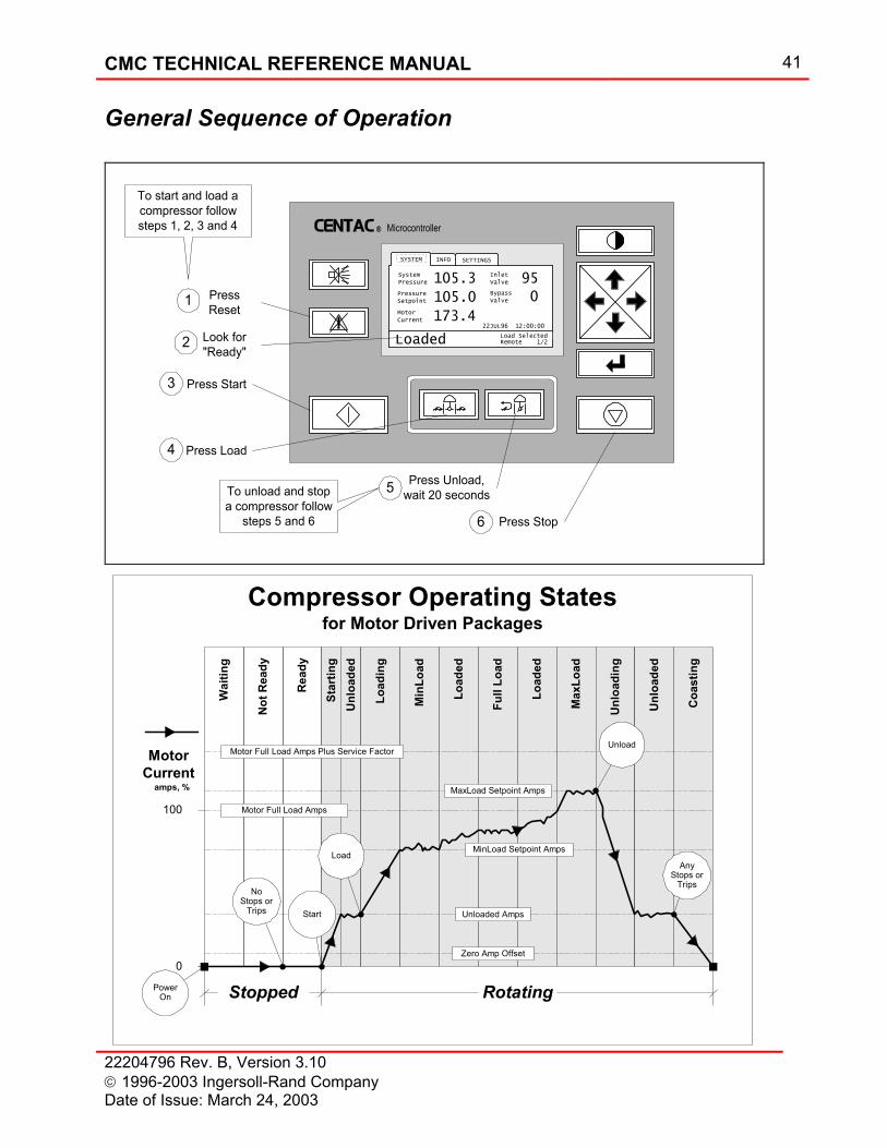
CMC TECHNICAL REFERENCE MANUAL 41
22204796 Rev. B, Version 3.10 1996-2003 Ingersoll-Rand Company Date of Issue: March 24, 2003
General Sequence of Operation
CENTAC Microcontroller
1/2
SETTINGSINFO
MotorCurrent
SystemPressure
PressureSetpoint
105.3
105.0
173.4
Loaded
InletValve
BypassValve
95
0
RemoteLoad Selected
22JUL96 12:00:00
SYSTEM
1 PressReset
2 Look for"Ready"
To start and load acompressor followsteps 1, 2, 3 and 4
Press Stop
Press Unload,wait 20 seconds5
6
To unload and stopa compressor follow
steps 5 and 6
Press Start3
4 Press Load
Unl
oade
d
Coa
stin
g
Star
ting
Load
ing
Load
ed
Min
Load
Full
Load
Load
ed
Max
Load
Unl
oadi
ng
Unl
oade
d
RotatingStopped
Not
Rea
dy
Rea
dy
Wai
ting
100
0
MotorCurrent
amps, %
NoStops or
Trips Start
Zero Amp Offset
Unloaded Amps
Motor Full Load Amps
Motor Full Load Amps Plus Service Factor
AnyStops or
Trips
Unload
MinLoad Setpoint AmpsLoad
MaxLoad Setpoint Amps
PowerOn
Compressor Operating Statesfor Motor Driven Packages
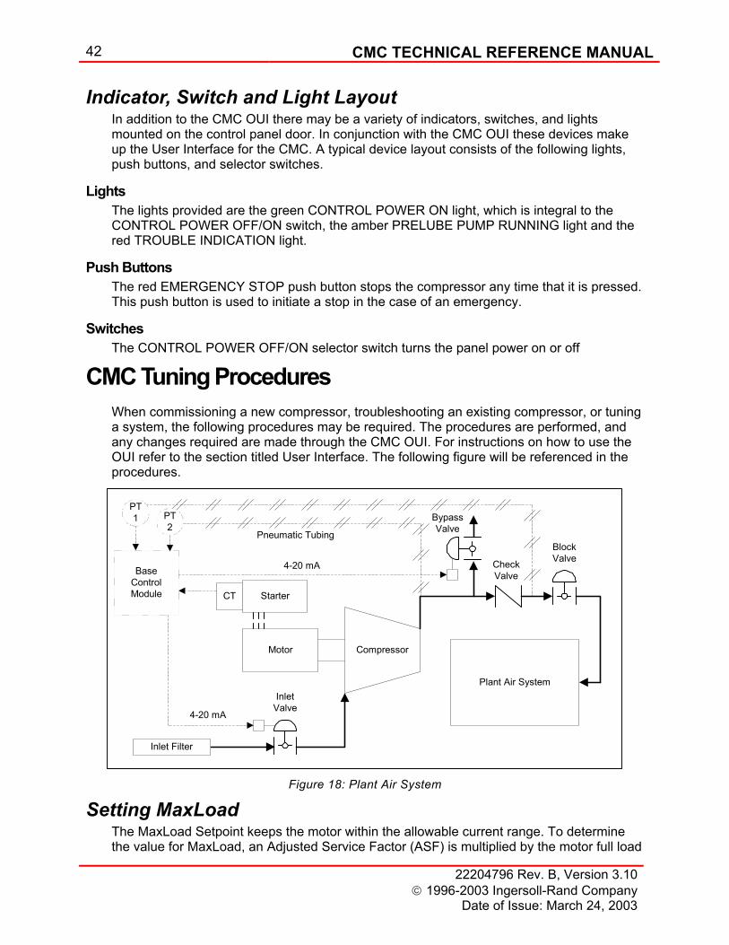
42 CMC TECHNICAL REFERENCE MANUAL
22204796 Rev. B, Version 3.10 1996-2003 Ingersoll-Rand Company
Date of Issue: March 24, 2003
Indicator, Switch and Light Layout In addition to the CMC OUI there may be a variety of indicators, switches, and lights mounted on the control panel door. In conjunction with the CMC OUI these devices make up the User Interface for the CMC. A typical device layout consists of the following lights, push buttons, and selector switches.
Lights The lights provided are the green CONTROL POWER ON light, which is integral to the CONTROL POWER OFF/ON switch, the amber PRELUBE PUMP RUNNING light and the red TROUBLE INDICATION light.
Push Buttons The red EMERGENCY STOP push button stops the compressor any time that it is pressed. This push button is used to initiate a stop in the case of an emergency.
Switches The CONTROL POWER OFF/ON selector switch turns the panel power on or off
CMC Tuning Procedures When commissioning a new compressor, troubleshooting an existing compressor, or tuning a system, the following procedures may be required. The procedures are performed, and any changes required are made through the CMC OUI. For instructions on how to use the OUI refer to the section titled User Interface. The following figure will be referenced in the procedures.
CompressorMotor
StarterCT
BypassValve
InletValve
CheckValveBase
ControlModule
PT1
4-20 mA
4-20 mA
PT2
Pneumatic Tubing
Plant Air System
Inlet Filter
BlockValve
Figure 18: Plant Air System
Setting MaxLoad The MaxLoad Setpoint keeps the motor within the allowable current range. To determine the value for MaxLoad, an Adjusted Service Factor (ASF) is multiplied by the motor full load
CMC TECHNICAL REFERENCE MANUAL 43
22204796 Rev. B, Version 3.10 1996-2003 Ingersoll-Rand Company Date of Issue: March 24, 2003
amps (FLA). The (ASF) is found by obtaining the motor service factor from the motor nameplate and selecting the adjustment factor from the table below. The motor full load amps is found on the motor nameplate.
Motor Service Factor Adjusted Service Factor 1.15 1.05 1.25 1.10
Example: MaxLoad = FLA X ASF FLA: 134 Amps Adjusted service factor: 1.05 MaxLoad: 140 Setting MinLoad
MinLoad establishes the minimum flow through the machine when loaded; it is the maximum point of inlet valve throttling. If system demand is below this throttle point, the compressor must bypass air or unload. If flow were allowed to go below MinLoad, the machine would eventually cross the surge line and surge. By stopping inlet valve throttling at MinLoad the machine is kept out of surge. To find the MinLoad setting, the machine is run into the surge line, and the value of load (amps, kilowatts, SCFM) at surge is recorded. The recorded value is then incremented by five percent and set as the value for MinLoad.
1. Before continuing this procedure, verify the following: a) The inlet and bypass control valves have been calibrated. b) The machine is running unloaded. c) The block valve at the inlet to the plant air system (Figure 18) is closed. d) The pressure setpoint is set to the pressure at which the machine is going to operate.
2. Set initial MinLoad estimates. a) In the Settings Folder, select the Edit Data cell for MinLoad. b) Increment or decrement the value to achieve a value of approximately 95% of full load amps.
3. Preset the manual bypass valve position to 100. a) On the OUI select the Settings Folder and enable manual valve control by highlighting the manual check box.
NOTE
When Manual is enabled, both control valves can be positioned while stopped, while only the Bypass Valve can be positioned when Loaded.
b) Switch to the System Folder Page 1 and press the Enter Key to enable edit mode. c) Use the horizontal navigation keys to select the bypass valve.

44 CMC TECHNICAL REFERENCE MANUAL
22204796 Rev. B, Version 3.10 1996-2003 Ingersoll-Rand Company
Date of Issue: March 24, 2003
d) Increment the value to position the valve to 100 percent. 4. Load the compressor by pressing the Load Key. 5. Find the throttled surge point.
a) Slowly decrement the bypass valve position until the last stage discharge pressure equals the pressure setpoint. b) Allow the system to stabilize at MinLoad. It the system does not stay at MinLoad, slightly decrement the valve position to force the machine to throttle to MinLoad. c) Decrement (MinLoad) 2%. d) Verify the last stage pressure equals the pressure setpoint and adjust the bypass valve position if necessary. e) Repeat c) and d) until the compressor surges.
6. Increase MinLoad by five percent. 7. Exit MinLoad editing by pressing the Enter Key. 8. Unload the machine. 9. Disable manual valve control by unchecking the manual check box.
Setting MinLoad Surge Index Increment When Surge Indexing is enabled (MinLoad Surge Index Increment is greater than zero), the Index Increment value is the amount added to the MinLoad Control Setpoint upon a surge. The MinLoad Control Setpoint will stop being incremented when and if the value reaches MaxLoad.
Setting Surge Sensitivity The Surge Sensitivity setting should be set sensitive enough to detect a surge, yet not trigger on spurious noise in the system. To set the surge sensor the machine is forced to surge by running the machine at MinLoad and the MinLoad setpoint is dropped until the machine audibly surges. The process is repeated until the correct setting is found.
1. Before continuing this procedure, verify the following: a) The plant can tolerate a pressure disturbance when the machine surges. b) Surge Indexing (by placing MinLoad Surge Index Increment to zero) is disabled. c) Surge Absorber is disabled. d) The pressure setpoint is set to the pressure at which the machine is going to
operate. e) The machine is running unloaded.
2. Set the initial Surge Sensitivity setting to 9. a) In the Settings Folder, select the Edit Data cell for Surge Sensitivity. b) Increment or decrement the value to achieve a setting of 9.
3. Press the Load Key.
CMC TECHNICAL REFERENCE MANUAL 45
22204796 Rev. B, Version 3.10 1996-2003 Ingersoll-Rand Company Date of Issue: March 24, 2003
4. Run the compressor at MinLoad and system pressure setpoint pressure. The
machine can be forced to MinLoad and to maintain system pressure setpoint by either. a) Running the plant at a higher pressure than pressure setpoint. b) Decreasing load in the plant. c) Verify the compressor is at pressure by observing the last stage pressure on
Page 2 of the Settings Folder. 5. Find the throttled surge point.
a) Select the MinLoad cell in the Settings Folder and slowly decrement the value until the machine surges. Typically the machine will make a puffing or popping noise upon surge, this is your indication surge has occurred.
6. Press the Unload Key. 7. Determine if Surge was recorded.
a) Inspect the Status Bar. If the message Surge Unload is displayed surge was recorded, if the message is not displayed surge was not recorded.
8. Check the Surge Sensitivity setting. a) If the surge was recorded, the setting may be correct or the Surge Sensor may be
too sensitive, skip to the too sensitive step, which follows. b) If the surge was not recorded, the setting is not sensitive enough, skip to the not
sensitive enough step, which follows. 9. Surge Sensor too sensitive.
a) Select the Surge Sensitivity Setting in the Settings Folder. b) Decrease the value for Surge Sensitivity by 0.1. c) Press the Reset Key. d) Skip to step 11.
10. Surge Sensor not sensitive enough. a) Select the Surge Sensitivity Setting in the Settings Folder. b) Increase the value for Surge Sensitivity by 0.1. c) Press the Reset Key.
11. Repeat the procedure until the Surge Sensitivity setting is found which just catches a surge but does not miss a surge. a) Return to step 3.
12. Restore MinLoad value.
Tuning Stability The CMC controls stability with four Proportion Integral Derivative (PID) control loops. When the machine is running above the MinLoad point and below the MaxLoad point, pressure is regulated with the Inlet Valve Pressure control loop. When the machine is running at the MinLoad point, pressure is regulated with the Bypass Valve Pressure control
46 CMC TECHNICAL REFERENCE MANUAL
22204796 Rev. B, Version 3.10 1996-2003 Ingersoll-Rand Company
Date of Issue: March 24, 2003
loop and motor current is regulated with the Inlet Valve MinLoad control loop. When the machine is running at MaxLoad motor current is regulated with the Inlet Valve MaxLoad control loop. For each PID loop, Proportional, Integral and Derivative parameters are used to stabilize the system. For a definition of the parameters and their effect on stability, refer to the section titled “How does Constant Pressure Modulation Work.” The proportional and integral terms are labeled by their respective loops, Inlet Valve, Bypass Valve, MinLoad, and MaxLoad.
Calibrating the Control Valves The purpose of this procedure is to position the inlet and bypass valves by opening and closing each valve from the CMC analog outputs. The valves should be adjusted to physically correspond with the valve positions displayed on the OUI. 1. Stop the compressor.
NOTE
Performing this procedure while the compressor is operating may cause serious damage.
2. On the OUI enable Setpoint changes by entering the password on the Settings Folder. 3. Verify the OUI status bar displays “Ready” or “Not Ready”. 4. On the OUI select the Settings Folder and enable manual valve control by highlighting
the manual check box.
NOTE
When Manual is enabled, both control valves can be positioned while stopped, while only the Bypass Valve can be positioned when Loaded.
5. Switch to the System Folder Page 1 and press the Enter Key to enable edit mode. 6. Use the horizontal navigation keys to select the valve requiring positioning. 7. Use the vertical arrows to increment and decrement the valve position sent to the
valve.
NOTE
For the Inlet and Bypass Valves, the displayed position corresponds to percent open.
8. Disable manual valve control by blanking the manual check box.
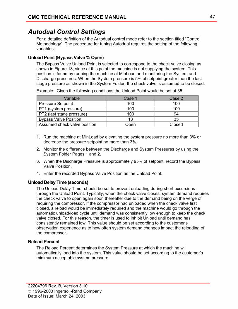
CMC TECHNICAL REFERENCE MANUAL 47
22204796 Rev. B, Version 3.10 1996-2003 Ingersoll-Rand Company Date of Issue: March 24, 2003
Autodual Control Settings For a detailed definition of the Autodual control mode refer to the section titled “Control Methodology”. The procedure for tuning Autodual requires the setting of the following variables:
Unload Point (Bypass Valve % Open) The Bypass Valve Unload Point is selected to correspond to the check valve closing as shown in Figure 18, since at this point the machine is not supplying the system. This position is found by running the machine at MinLoad and monitoring the System and Discharge pressures. When the System pressure is 5% of setpoint greater than the last stage pressure as shown in the System Folder, the check valve is assumed to be closed. Example: Given the following conditions the Unload Point would be set at 35.
Variable Case 1 Case 2 Pressure Setpoint 100 100 PT1 (system pressure) 100 100 PT2 (last stage pressure) 100 94 Bypass Valve Position 13 35 Assumed check valve position Open Closed
1. Run the machine at MinLoad by elevating the system pressure no more than 3% or
decrease the pressure setpoint no more than 3%. 2. Monitor the difference between the Discharge and System Pressures by using the
System Folder Pages 1 and 2. 3. When the Discharge Pressure is approximately 95% of setpoint, record the Bypass
Valve Position. 4. Enter the recorded Bypass Valve Position as the Unload Point.
Unload Delay Time (seconds) The Unload Delay Timer should be set to prevent unloading during short excursions through the Unload Point. Typically, when the check valve closes, system demand requires the check valve to open again soon thereafter due to the demand being on the verge of requiring the compressor. If the compressor had unloaded when the check valve first closed, a reload would be immediately required and the machine would go through the automatic unload/load cycle until demand was consistently low enough to keep the check valve closed. For this reason, the timer is used to inhibit Unload until demand has consistently remained low. This value should be set according to the customer’s observation experience as to how often system demand changes impact the reloading of the compressor.
Reload Percent The Reload Percent determines the System Pressure at which the machine will automatically load into the system. This value should be set according to the customer’s minimum acceptable system pressure.
48 CMC TECHNICAL REFERENCE MANUAL
22204796 Rev. B, Version 3.10 1996-2003 Ingersoll-Rand Company
Date of Issue: March 24, 2003
Setting the Start Time The Start Time is set to the transition time of a built-in reduced voltage starter or the acceleration time of a customer supplied starter. This procedure requires the Inlet Unload Position to have been set.
CAUTION
Damage to the starter contacts could result if starter transition occurs before the compressor is up to full speed.
1. Initially set the Start Time to 25 Seconds. 2. Stop the compressor. Allow compressor to coast to a stop. 3. On the OUI record the time and press the start button. 4. Wait for the compressor to stop accelerating and again record the time. 5. Calculate the difference between the two values and enter as the Start Time.
Setting the CT Ratio Locate the CT and find the rating, which is typically printed, on the side of the CT. Divide the primary by the secondary and enter the value as the CT Ratio.
Example: CT is printed with 600:5, the value entered is 120.
Inlet Unload Position The purpose of this variable is to set the inlet valve position when the machine is running unloaded. For a description of the Unloaded state refer to the section titled “Unload”.
1. If the inlet valve is a butterfly type, enter an initial value for Inlet Unload Position of 15. If the inlet valve is a inlet guide vane type, enter an initial value for Inlet Unload Position of 5.
2. Start the machine. If during startup the motor trips on overload, draws what is considered excessive amperage or sounds labored, stop the machine and decrease the Unload Position by 2 and restart the machine.
3. Run the machine in the Unloaded state and monitor the first stage pressure. 4. Adjust the Unload Position to achieve 1 PSIG on the first stage discharge, or until a
positive pressure is felt at the first stage condensate trap bypass. 5. If the inlet air temperature is relatively cold, increase the setting 2%, this will
accommodate hot day operation.
Setting Set Point Ramp Rate Setpoint ramp rate determines the rate at which the machine transitions from unloaded to loaded. The setting should be set as high as possible without creating excessive overshoot when the machine enters the system.
1. Verify the machine is unloaded by the “Unloaded” message in the OUI Status Bar.
CMC TECHNICAL REFERENCE MANUAL 49
22204796 Rev. B, Version 3.10 1996-2003 Ingersoll-Rand Company Date of Issue: March 24, 2003
2. Determine overshoot. a) Load the machine. b) Monitor the pressure overshoot.
3. If overshoot is excessive. a) Decrease the Setpoint Ramp Rate. b) Repeat step 2.
4. If overshoot is satisfactory and time to load is excessive. a) Increase the Setpoint Ramp Rate. b) Repeat step 2.
5. If overshoot is satisfactory and time to load is satisfactory the Setpoint Ramp Rate is correct.
Alarm and Trip Settings The values for vibration, temperature, pressure etc. alarm and trip setpoints are located on the electrical schematic. These values determine when the controller will indicate an alarm or trip condition.
WARNING
Setting Trip values outside the range specified on the drawings can result in compressor damage.
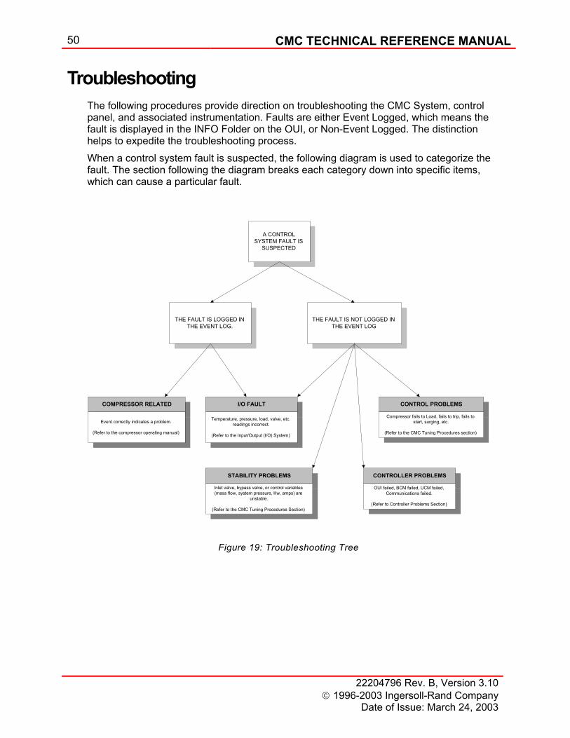
50 CMC TECHNICAL REFERENCE MANUAL
22204796 Rev. B, Version 3.10 1996-2003 Ingersoll-Rand Company
Date of Issue: March 24, 2003
Troubleshooting The following procedures provide direction on troubleshooting the CMC System, control panel, and associated instrumentation. Faults are either Event Logged, which means the fault is displayed in the INFO Folder on the OUI, or Non-Event Logged. The distinction helps to expedite the troubleshooting process. When a control system fault is suspected, the following diagram is used to categorize the fault. The section following the diagram breaks each category down into specific items, which can cause a particular fault.
I/O FAULT
Temperature, pressure, load, valve, etc.readings incorrect.
(Refer to the Input/Output (I/O) System)
COMPRESSOR RELATED
Event correctly indicates a problem.
(Refer to the compressor operating manual)
STABILITY PROBLEMS
Inlet valve, bypass valve, or control variables(mass flow, system pressure, Kw, amps) are
unstable.
(Refer to the CMC Tuning Procedures Section)
CONTROL PROBLEMS
Compressor fails to Load, fails to trip, fails tostart, surging, etc.
(Refer to the CMC Tuning Procedures section)
CONTROLLER PROBLEMS
OUI failed, BCM failed, UCM failed,Communications failed.
(Refer to Controller Problems Section)
A CONTROLSYSTEM FAULT IS
SUSPECTED
THE FAULT IS LOGGED INTHE EVENT LOG.
THE FAULT IS NOT LOGGED INTHE EVENT LOG
Figure 19: Troubleshooting Tree
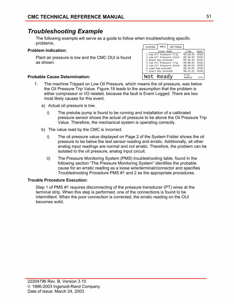
CMC TECHNICAL REFERENCE MANUAL 51
22204796 Rev. B, Version 3.10 1996-2003 Ingersoll-Rand Company Date of Issue: March 24, 2003
2/6
SYSTEM SETTINGSINFO
Not Ready RemoteTrip
Event Name Time Date
1 Low Oil Pressure Trip 09:18:44 0720 2 Low Oil Pressure Alarm 09:18:43 0720 3 Reset key pressed 09:18:34 0720 4 Low Oil Pressure Trip 09:08:43 0720 5 Low Oil Pressure Alarm 08:58:23 0720 6 Load key pressed 08:24:01 0720 7 Start key pressed 08:23:12 0720
Troubleshooting Example The following example will serve as a guide to follow when troubleshooting specific problems.
Problem Indication: Plant air pressure is low and the CMC OUI is found as shown.
Probable Cause Determination: 1. The machine Tripped on Low Oil Pressure, which means the oil pressure, was below
the Oil Pressure Trip Value. Figure 19 leads to the assumption that the problem is either compressor or I/O related, because the fault is Event Logged. There are two most likely causes for this event.
a) Actual oil pressure is low. i) The prelube pump is found to be running and installation of a calibrated
pressure sensor shows the actual oil pressure to be above the Oil Pressure Trip Value. Therefore, the mechanical system is operating correctly.
b) The value read by the CMC is incorrect. i) The oil pressure value displayed on Page 2 of the System Folder shows the oil
pressure to be below the test sensor reading and erratic. Additionally, all other analog input readings are normal and not erratic. Therefore, the problem can be isolated to the oil pressure, analog input circuit.
ii) The Pressure Monitoring System (PMS) troubleshooting table, found in the following section “The Pressure Monitoring System” identifies the probable cause for an erratic reading as a loose wire/terminal/connector and specifies Troubleshooting Procedure PMS #1 and 2 as the appropriate procedures.
Trouble Procedure Execution: Step 1 of PMS #1 requires disconnecting of the pressure transducer (PT) wires at the terminal strip. When this step is performed, one of the connections is found to be intermittent. When the poor connection is corrected, the erratic reading on the OUI becomes solid.
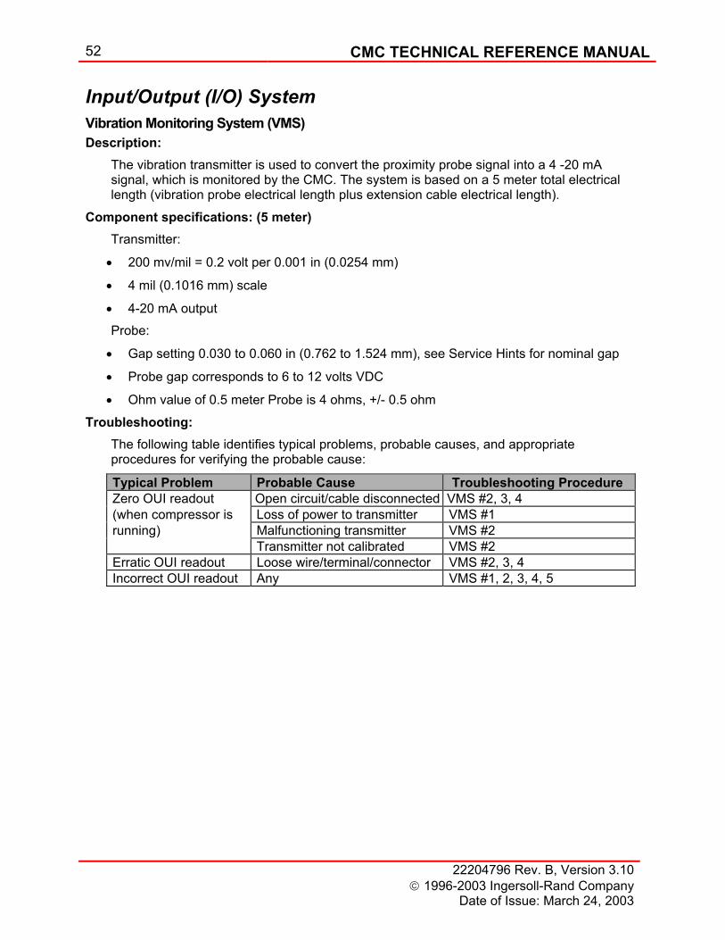
52 CMC TECHNICAL REFERENCE MANUAL
22204796 Rev. B, Version 3.10 1996-2003 Ingersoll-Rand Company
Date of Issue: March 24, 2003
Input/Output (I/O) System Vibration Monitoring System (VMS) Description:
The vibration transmitter is used to convert the proximity probe signal into a 4 -20 mA signal, which is monitored by the CMC. The system is based on a 5 meter total electrical length (vibration probe electrical length plus extension cable electrical length).
Component specifications: (5 meter) Transmitter:
• 200 mv/mil = 0.2 volt per 0.001 in (0.0254 mm)
• 4 mil (0.1016 mm) scale
• 4-20 mA output Probe:
• Gap setting 0.030 to 0.060 in (0.762 to 1.524 mm), see Service Hints for nominal gap
• Probe gap corresponds to 6 to 12 volts VDC
• Ohm value of 0.5 meter Probe is 4 ohms, +/- 0.5 ohm
Troubleshooting: The following table identifies typical problems, probable causes, and appropriate procedures for verifying the probable cause:
Typical Problem Probable Cause Troubleshooting Procedure Zero OUI readout Open circuit/cable disconnected VMS #2, 3, 4 (when compressor is Loss of power to transmitter VMS #1 running) Malfunctioning transmitter VMS #2 Transmitter not calibrated VMS #2 Erratic OUI readout Loose wire/terminal/connector VMS #2, 3, 4 Incorrect OUI readout Any VMS #1, 2, 3, 4, 5
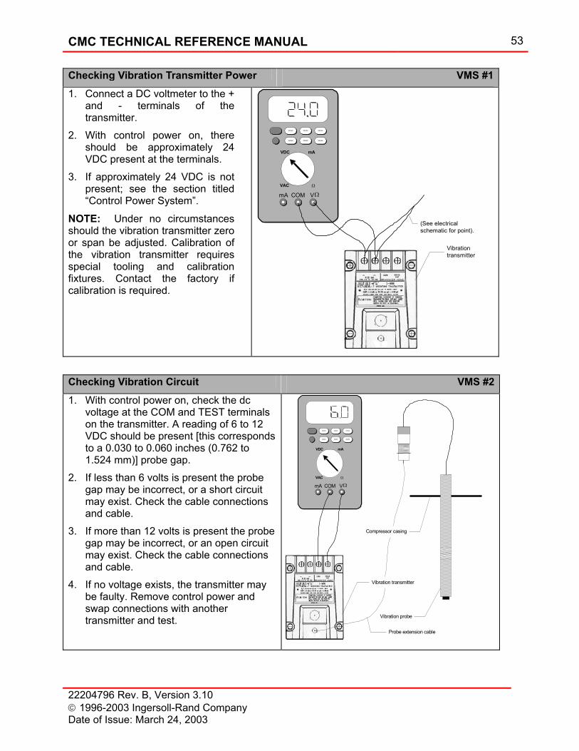
CMC TECHNICAL REFERENCE MANUAL 53
22204796 Rev. B, Version 3.10 1996-2003 Ingersoll-Rand Company Date of Issue: March 24, 2003
Checking Vibration Transmitter Power VMS #11. Connect a DC voltmeter to the +
and - terminals of the transmitter.
2. With control power on, there should be approximately 24 VDC present at the terminals.
3. If approximately 24 VDC is not present; see the section titled “Control Power System”.
NOTE: Under no circumstances should the vibration transmitter zero or span be adjusted. Calibration of the vibration transmitter requires special tooling and calibration fixtures. Contact the factory if calibration is required.
Vibrationtransmitter
VDC mA
VAC Ω
mA COM V
XXXXX XXXXX XXXXX
XXXXX XXXXX XXXXX
Ω
(See electricalschematic for point).
Checking Vibration Circuit VMS #21. With control power on, check the dc
voltage at the COM and TEST terminals on the transmitter. A reading of 6 to 12 VDC should be present [this corresponds to a 0.030 to 0.060 inches (0.762 to 1.524 mm)] probe gap.
2. If less than 6 volts is present the probe gap may be incorrect, or a short circuit may exist. Check the cable connections and cable.
3. If more than 12 volts is present the probe gap may be incorrect, or an open circuit may exist. Check the cable connections and cable.
4. If no voltage exists, the transmitter may be faulty. Remove control power and swap connections with another transmitter and test.
VDC mA
VAC Ω
mA COM V
XXXXX XXXXX XXXXX
XXXXX XXXXX XXXXX
Ω
Probe extension cable
Vibration probe
Compressor casing
Vibration transmitter
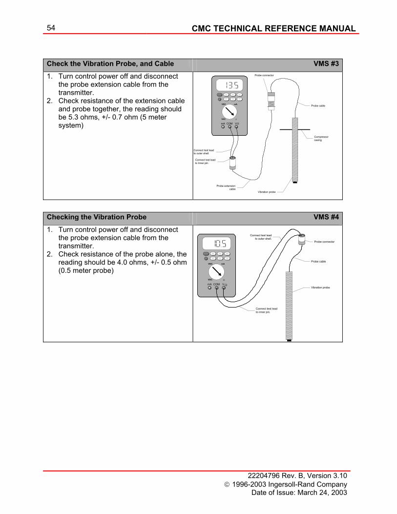
54 CMC TECHNICAL REFERENCE MANUAL
22204796 Rev. B, Version 3.10 1996-2003 Ingersoll-Rand Company
Date of Issue: March 24, 2003
Check the Vibration Probe, and Cable VMS #31. Turn control power off and disconnect
the probe extension cable from the transmitter.
2. Check resistance of the extension cable and probe together, the reading should be 5.3 ohms, +/- 0.7 ohm (5 meter system)
Probe cableVDC mA
VAC Ω
mA COM V
XXXXX XXXXX XXXXX
XXXXX XXXXX XXXXX
Ω
Probe extensioncable
Vibration probe
Compressorcasing
Connect test leadto inner pin.
Connect test leadto outer shell.
Probe connector
Checking the Vibration Probe VMS #41. Turn control power off and disconnect
the probe extension cable from the transmitter.
2. Check resistance of the probe alone, the reading should be 4.0 ohms, +/- 0.5 ohm (0.5 meter probe)
VDC mA
VAC Ω
mA COM V
XXXXX XXXXX XXXXX
XXXXX XXXXX XXXXX
Ω
Connect test leadto outer shell.
Connect test leadto inner pin.
Vibration probe
Probe cable
Probe connector
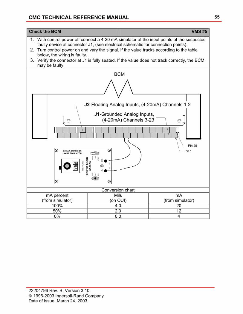
CMC TECHNICAL REFERENCE MANUAL 55
22204796 Rev. B, Version 3.10 1996-2003 Ingersoll-Rand Company Date of Issue: March 24, 2003
Check the BCM VMS #5
1. With control power off connect a 4-20 mA simulator at the input points of the suspected faulty device at connector J1, (see electrical schematic for connection points).
2. Turn control power on and vary the signal. If the value tracks according to the table below, the wiring is faulty.
3. Verify the connector at J1 is fully seated. If the value does not track correctly, the BCM may be faulty.
J2-Floating Analog Inputs, (4-20mA) Channels 1-2
J1-Grounded Analog Inputs,(4-20mA) Channels 3-23
Pin 1Pin 25
mA O
UT
2 WIR
E
OFF
100%
00.0%
DIAL
BATTERYCHECK
LOO
PO
N
XXXXXXM
OD
EL CL-XXX
00.0% - 100%
555
4-20 mA SURCE OR2 WIRE SIMULATOR
BCM
Conversion chart
mA percent (from simulator)
Mils (on OUI)
mA (from simulator)
100% 4.0 20 50% 2.0 12 0% 0.0 4
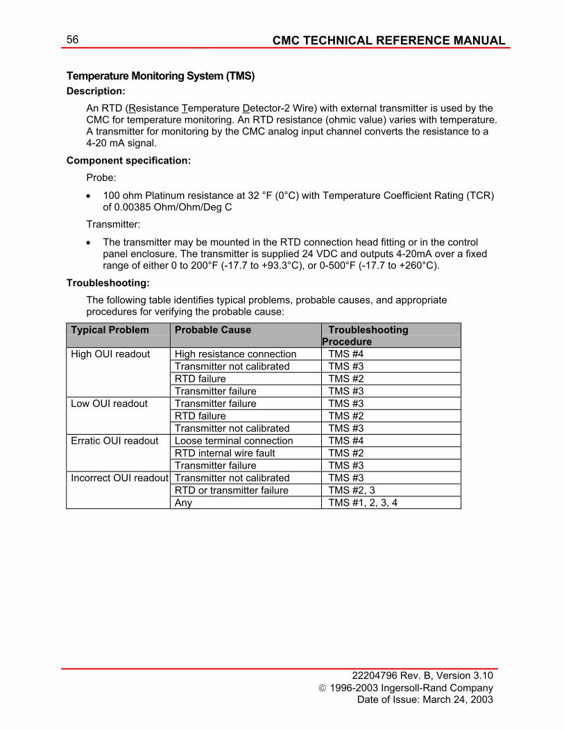
56 CMC TECHNICAL REFERENCE MANUAL
22204796 Rev. B, Version 3.10 1996-2003 Ingersoll-Rand Company
Date of Issue: March 24, 2003
Temperature Monitoring System (TMS) Description:
An RTD (Resistance Temperature Detector-2 Wire) with external transmitter is used by the CMC for temperature monitoring. An RTD resistance (ohmic value) varies with temperature. A transmitter for monitoring by the CMC analog input channel converts the resistance to a 4-20 mA signal.
Component specification: Probe:
• 100 ohm Platinum resistance at 32 °F (0°C) with Temperature Coefficient Rating (TCR) of 0.00385 Ohm/Ohm/Deg C
Transmitter:
• The transmitter may be mounted in the RTD connection head fitting or in the control panel enclosure. The transmitter is supplied 24 VDC and outputs 4-20mA over a fixed range of either 0 to 200°F (-17.7 to +93.3°C), or 0-500°F (-17.7 to +260°C).
Troubleshooting: The following table identifies typical problems, probable causes, and appropriate procedures for verifying the probable cause:
Typical Problem Probable Cause Troubleshooting Procedure
High OUI readout High resistance connection TMS #4 Transmitter not calibrated TMS #3 RTD failure TMS #2 Transmitter failure TMS #3 Low OUI readout Transmitter failure TMS #3 RTD failure TMS #2 Transmitter not calibrated TMS #3 Erratic OUI readout Loose terminal connection TMS #4 RTD internal wire fault TMS #2 Transmitter failure TMS #3 Incorrect OUI readout Transmitter not calibrated TMS #3 RTD or transmitter failure TMS #2, 3 Any TMS #1, 2, 3, 4
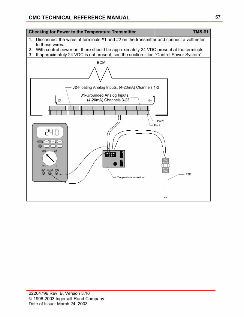
CMC TECHNICAL REFERENCE MANUAL 57
22204796 Rev. B, Version 3.10 1996-2003 Ingersoll-Rand Company Date of Issue: March 24, 2003
Checking for Power to the Temperature Transmitter TMS #11. Disconnect the wires at terminals #1 and #2 on the transmitter and connect a voltmeter
to these wires. 2. With control power on, there should be approximately 24 VDC present at the terminals. 3. If approximately 24 VDC is not present, see the section titled “Control Power System”.
1 2 3 4
Temperature transmitterRTD
J2-Floating Analog Inputs, (4-20mA) Channels 1-2
J1-Grounded Analog Inputs,(4-20mA) Channels 3-23
Pin 1Pin 25
BCM
VDC mA
VAC Ω
mA COM V
XXXXX XXXXX XXXXX
XXXXX XXXXX XXXXX
Ω
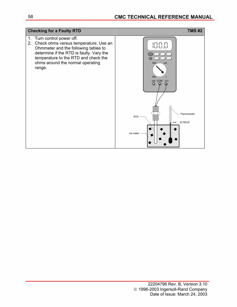
58 CMC TECHNICAL REFERENCE MANUAL
22204796 Rev. B, Version 3.10 1996-2003 Ingersoll-Rand Company
Date of Issue: March 24, 2003
Checking for a Faulty RTD TMS #21. Turn control power off. 2. Check ohms versus temperature. Use an
Ohmmeter and the following tables to determine if the RTD is faulty. Vary the temperature to the RTD and check the ohms around the normal operating range.
ThermometerRTD
32 DEGF
Ice water
VDC mA
VAC Ω
mA COM V
XXXXX XXXXX XXXXX
XXXXX XXXXX XXXXX
Ω
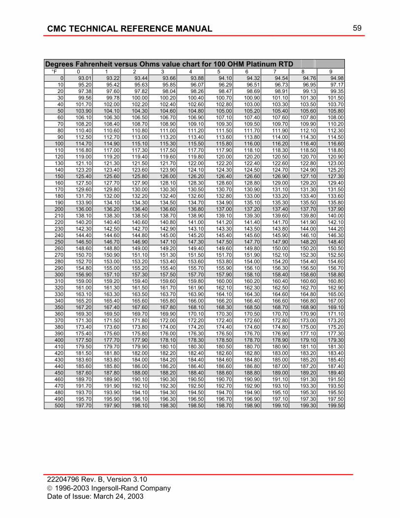
CMC TECHNICAL REFERENCE MANUAL 59
22204796 Rev. B, Version 3.10 1996-2003 Ingersoll-Rand Company Date of Issue: March 24, 2003
Degrees Fahrenheit versus Ohms value chart for 100 OHM Platinum RTD °F 0 1 2 3 4 5 6 7 8 9
0 93.01 93.22 93.44 93.66 93.88 94.10 94.32 94.54 94.76 94.9810 95.20 95.42 95.63 95.85 96.07 96.29 96.51 96.73 96.95 97.1720 97.38 97.60 97.82 98.04 98.26 98.47 98.69 98.91 99.13 99.3530 99.56 99.78 100.00 100.20 100.40 100.70 100.90 101.10 101.30 101.5040 101.70 102.00 102.20 102.40 102.60 102.80 103.00 103.30 103.50 103.7050 103.90 104.10 104.30 104.60 104.80 105.00 105.20 105.40 105.60 105.8060 106.10 106.30 106.50 106.70 106.90 107.10 107.40 107.60 107.80 108.0070 108.20 108.40 108.70 108.90 109.10 109.30 109.50 109.70 109.90 110.2080 110.40 110.60 110.80 111.00 111.20 111.50 111.70 111.90 112.10 112.3090 112.50 112.70 113.00 113.20 113.40 113.60 113.80 114.00 114.30 114.50
100 114.70 114.90 115.10 115.30 115.50 115.80 116.00 116.20 116.40 116.60110 116.80 117.00 117.30 117.50 117.70 117.90 118.10 118.30 118.50 118.80120 119.00 119.20 119.40 119.60 119.80 120.00 120.20 120.50 120.70 120.90130 121.10 121.30 121.50 121.70 122.00 122.20 122.40 122.60 122.80 123.00140 123.20 123.40 123.60 123.90 124.10 124.30 124.50 124.70 124.90 125.20150 125.40 125.60 125.80 126.00 126.20 126.40 126.60 126.90 127.10 127.30160 127.50 127.70 127.90 128.10 128.30 128.60 128.80 129.00 129.20 129.40170 129.60 129.80 130.00 130.30 130.50 130.70 130.90 131.10 131.30 131.50180 131.70 132.00 132.20 132.40 132.60 132.80 133.00 133.20 133.40 133.60190 133.90 134.10 134.30 134.50 134.70 134.90 135.10 135.30 135.50 135.80200 136.00 136.20 136.40 136.60 136.80 137.00 137.20 137.40 137.70 137.90210 138.10 138.30 138.50 138.70 138.90 139.10 139.30 139.60 139.80 140.00220 140.20 140.40 140.60 140.80 141.00 141.20 141.40 141.70 141.90 142.10230 142.30 142.50 142.70 142.90 143.10 143.30 143.50 143.80 144.00 144.20240 144.40 144.60 144.80 145.00 145.20 145.40 145.60 145.90 146.10 146.30250 146.50 146.70 146.90 147.10 147.30 147.50 147.70 147.90 148.20 148.40260 148.60 148.80 149.00 149.20 149.40 149.60 149.80 150.00 150.20 150.50270 150.70 150.90 151.10 151.30 151.50 151.70 151.90 152.10 152.30 152.50280 152.70 153.00 153.20 153.40 153.60 153.80 154.00 154.20 154.40 154.60290 154.80 155.00 155.20 155.40 155.70 155.90 156.10 156.30 156.50 156.70300 156.90 157.10 157.30 157.50 157.70 157.90 158.10 158.40 158.60 158.80310 159.00 159.20 159.40 159.60 159.80 160.00 160.20 160.40 160.60 160.80320 161.00 161.30 161.50 161.70 161.90 162.10 162.30 162.50 162.70 162.90330 163.10 163.30 163.50 163.70 163.90 164.10 164.30 164.60 164.80 165.00340 165.20 165.40 165.60 165.80 166.00 166.20 166.40 166.60 166.80 167.00350 167.20 167.40 167.60 167.80 168.10 168.30 168.50 168.70 168.90 169.10360 169.30 169.50 169.70 169.90 170.10 170.30 170.50 170.70 170.90 171.10370 171.30 171.50 171.80 172.00 172.20 172.40 172.60 172.80 173.00 173.20380 173.40 173.60 173.80 174.00 174.20 174.40 174.60 174.80 175.00 175.20390 175.40 175.60 175.80 176.00 176.30 176.50 176.70 176.90 177.10 177.30400 177.50 177.70 177.90 178.10 178.30 178.50 178.70 178.90 179.10 179.30410 179.50 179.70 179.90 180.10 180.30 180.50 180.70 180.90 181.10 181.30420 181.50 181.80 182.00 182.20 182.40 182.60 182.80 183.00 183.20 183.40430 183.60 183.80 184.00 184.20 184.40 184.60 184.80 185.00 185.20 185.40440 185.60 185.80 186.00 186.20 186.40 186.60 186.80 187.00 187.20 187.40450 187.60 187.80 188.00 188.20 188.40 188.60 188.80 189.00 189.20 189.40460 189.70 189.90 190.10 190.30 190.50 190.70 190.90 191.10 191.30 191.50470 191.70 191.90 192.10 192.30 192.50 192.70 192.90 193.10 193.30 193.50480 193.70 193.90 194.10 194.30 194.50 194.70 194.90 195.10 195.30 195.50490 195.70 195.90 196.10 196.30 196.50 196.70 196.90 197.10 197.30 197.50500 197.70 197.90 198.10 198.30 198.50 198.70 198.90 199.10 199.30 199.50
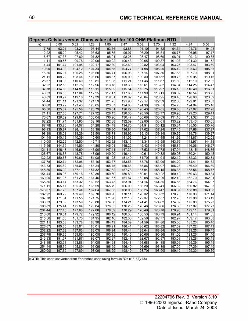
60 CMC TECHNICAL REFERENCE MANUAL
22204796 Rev. B, Version 3.10 1996-2003 Ingersoll-Rand Company
Date of Issue: March 24, 2003
Degrees Celsius versus Ohms value chart for 100 OHM Platinum RTD °C 0.00 0.62 1.23 1.85 2.47 3.09 3.70 4.32 4.94 5.56
-17.78 93.01 93.22 93.44 93.66 93.88 94.10 94.32 94.54 94.76 94.98-12.22 95.20 95.42 95.63 95.85 96.07 96.29 96.51 96.73 96.95 97.17-6.67 97.38 97.60 97.82 98.04 98.26 98.47 98.69 98.91 99.13 99.35-1.11 99.56 99.78 100.00 100.22 100.43 100.65 100.87 101.08 101.30 101.524.44 101.74 101.95 102.17 102.39 102.60 102.82 103.04 103.25 103.47 103.69
10.00 103.90 104.12 104.34 104.55 104.77 104.98 105.20 105.42 105.63 105.8515.56 106.07 106.28 106.50 106.71 106.93 107.14 107.36 107.58 107.79 108.0121.11 108.22 108.44 108.66 108.87 109.09 109.30 109.52 109.73 109.95 110.1626.67 110.38 110.60 110.81 111.03 111.24 111.46 111.67 111.89 112.10 112.3232.22 112.53 112.75 112.96 113.18 113.39 113.61 113.82 114.04 114.25 114.4737.78 114.68 114.89 115.11 115.32 115.54 115.75 115.97 116.18 116.40 116.6143.33 116.83 117.04 117.25 117.47 117.68 117.90 118.11 118.32 118.54 118.7548.89 118.97 119.18 119.39 119.61 119.82 120.04 120.25 120.46 120.68 120.8954.44 121.11 121.32 121.53 121.75 121.96 122.17 122.39 122.60 122.81 123.0360.00 123.22 123.43 123.65 123.87 124.08 124.30 124.51 124.73 124.94 125.1665.56 125.37 125.58 125.79 126.01 126.22 126.43 126.65 126.86 127.07 127.2871.11 127.50 127.71 127.92 128.13 128.35 128.56 128.77 128.98 129.20 129.4176.67 129.62 129.83 130.04 130.26 130.47 130.68 130.89 131.10 131.32 131.5382.22 131.74 131.95 132.16 132.38 132.59 132.80 133.01 133.22 133.43 133.6587.78 133.86 134.07 134.28 134.49 134.70 134.91 135.12 135.34 135.55 135.7693.33 135.97 136.18 136.39 136.60 136.81 137.02 137.24 137.45 137.66 137.8798.89 138.08 138.29 138.50 138.71 138.92 139.13 139.34 139.55 139.76 139.97
104.44 140.18 140.39 140.60 140.81 141.02 141.24 141.45 141.66 141.87 142.08110.00 142.29 142.50 142.71 142.92 143.13 143.34 143.55 143.76 143.97 144.18115.56 144.39 144.59 144.80 145.01 145.22 145.43 145.64 145.85 146.06 146.27121.11 146.48 146.69 146.90 147.11 147.32 147.53 147.73 147.94 148.15 148.36126.67 148.57 148.78 148.99 149.20 149.41 149.61 149.82 150.03 150.24 150.45132.22 150.66 150.87 151.08 151.28 151.49 151.70 151.91 152.12 152.33 152.54137.78 152.74 152.95 153.16 153.37 153.58 153.78 153.99 154.20 154.41 154.62143.33 154.82 155.03 155.24 155.45 155.66 155.86 156.07 156.28 156.49 156.69148.89 156.90 157.11 157.32 157.52 157.73 157.94 158.15 158.35 158.56 158.77154.44 158.98 159.18 159.39 159.60 159.80 160.01 160.22 160.42 160.63 160.84160.00 161.05 161.25 161.46 161.67 161.87 162.08 162.29 162.49 162.70 162.91165.56 163.11 163.32 163.52 163.73 163.94 164.14 164.35 164.56 164.76 164.97171.11 165.17 165.38 165.59 165.79 166.00 166.20 166.41 166.62 166.82 167.03176.67 167.23 167.44 167.64 167.85 168.06 168.26 168.47 168.67 168.88 169.08182.22 169.29 169.49 169.70 169.90 170.11 170.32 170.52 170.73 170.93 171.14187.78 171.34 171.55 171.75 171.96 172.16 172.37 172.57 172.78 172.98 173.19193.33 173.39 173.59 173.80 174.00 174.21 174.41 174.62 174.82 175.03 175.23198.89 175.44 175.64 175.84 176.05 176.25 176.46 176.66 176.86 177.07 177.27204.44 177.48 177.68 177.88 178.09 178.29 178.49 178.70 178.90 179.11 179.31210.00 179.51 179.72 179.92 180.12 180.33 180.53 180.73 180.94 181.14 181.35215.56 181.55 181.75 181.95 182.16 182.36 182.56 182.77 182.97 183.17 183.38221.11 183.58 183.78 183.98 184.19 184.39 184.59 184.80 185.00 185.20 185.40226.67 185.60 185.81 186.01 186.21 186.41 186.62 186.82 187.02 187.22 187.43232.22 187.63 187.83 188.03 188.24 188.44 188.64 188.84 189.04 189.25 189.45237.78 189.65 189.85 190.05 190.25 190.46 190.66 190.86 191.06 191.26 191.46243.33 191.67 191.87 192.07 192.27 192.47 192.67 192.87 193.08 193.28 193.48248.89 193.68 193.88 194.08 194.28 194.48 194.68 194.88 195.09 195.29 195.49254.44 195.69 195.89 196.09 196.29 196.49 196.69 196.89 197.09 197.29 197.49260.00 197.69 197.89 198.09 198.29 198.49 198.70 198.90 199.10 199.30 199.50
NOTE: This chart converted from Fahrenheit chart using formula °C= ((°F-32)/1.8)
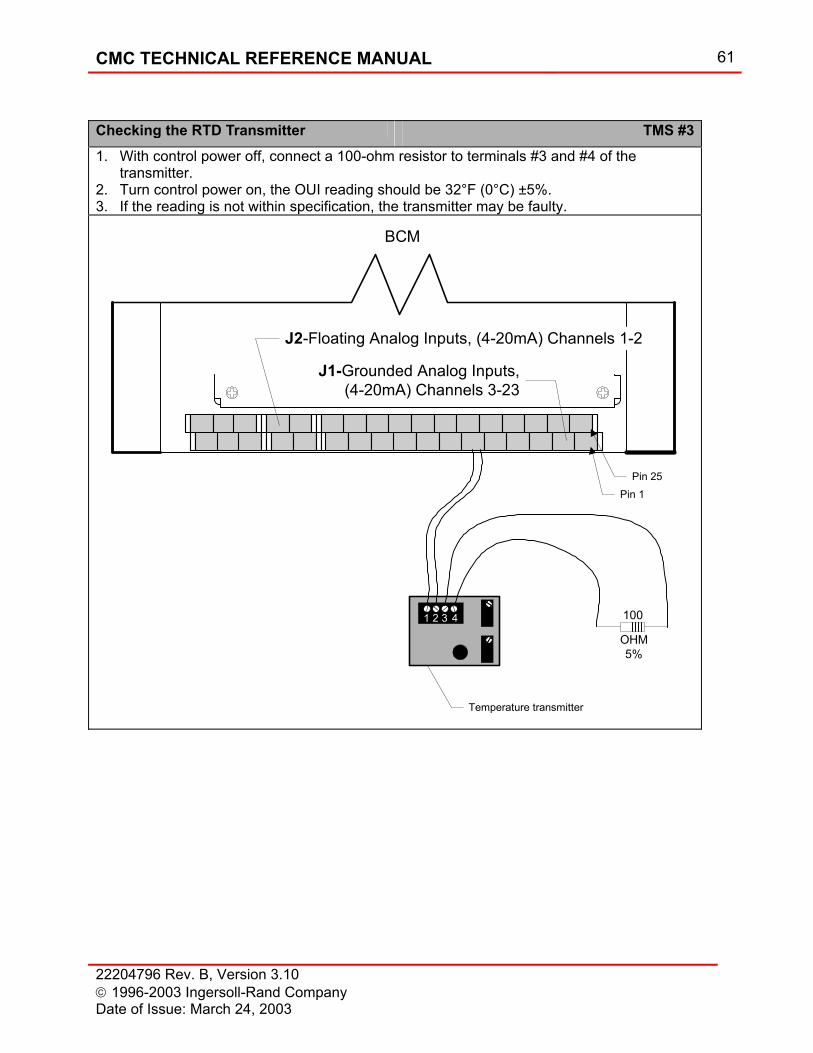
CMC TECHNICAL REFERENCE MANUAL 61
22204796 Rev. B, Version 3.10 1996-2003 Ingersoll-Rand Company Date of Issue: March 24, 2003
Checking the RTD Transmitter TMS #31. With control power off, connect a 100-ohm resistor to terminals #3 and #4 of the
transmitter. 2. Turn control power on, the OUI reading should be 32°F (0°C) ±5%. 3. If the reading is not within specification, the transmitter may be faulty.
1 2 3 4
Temperature transmitter
J2-Floating Analog Inputs, (4-20mA) Channels 1-2
J1-Grounded Analog Inputs,(4-20mA) Channels 3-23
Pin 1Pin 25
BCM
100
OHM5%
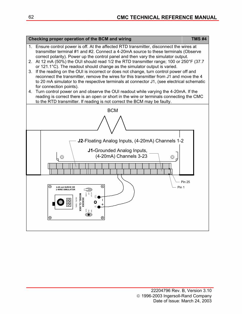
62 CMC TECHNICAL REFERENCE MANUAL
22204796 Rev. B, Version 3.10 1996-2003 Ingersoll-Rand Company
Date of Issue: March 24, 2003
Checking proper operation of the BCM and wiring TMS #41. Ensure control power is off. At the affected RTD transmitter, disconnect the wires at
transmitter terminal #1 and #2. Connect a 4-20mA source to these terminals (Observe correct polarity). Power up the control panel and then vary the simulator output.
2. At 12 mA (50%) the OUI should read 1/2 the RTD transmitter range; 100 or 250°F (37.7 or 121.1°C). The readout should change as the simulator output is varied.
3. If the reading on the OUI is incorrect or does not change, turn control power off and reconnect the transmitter, remove the wires for this transmitter from J1 and move the 4 to 20 mA simulator to the respective terminals at connector J1, (see electrical schematic for connection points).
4. Turn control power on and observe the OUI readout while varying the 4-20mA. If the reading is correct there is an open or short in the wire or terminals connecting the CMC to the RTD transmitter. If reading is not correct the BCM may be faulty.
J2-Floating Analog Inputs, (4-20mA) Channels 1-2
J1-Grounded Analog Inputs,(4-20mA) Channels 3-23
Pin 1Pin 25
mA O
UT
2 WIR
E
OFF
100%
00.0%
DIAL
BATTERYCHECK
LOO
PO
N
XXXXXXM
OD
EL CL-XXX
00.0% - 100%
555
4-20 mA SURCE OR2 WIRE SIMULATOR
BCM
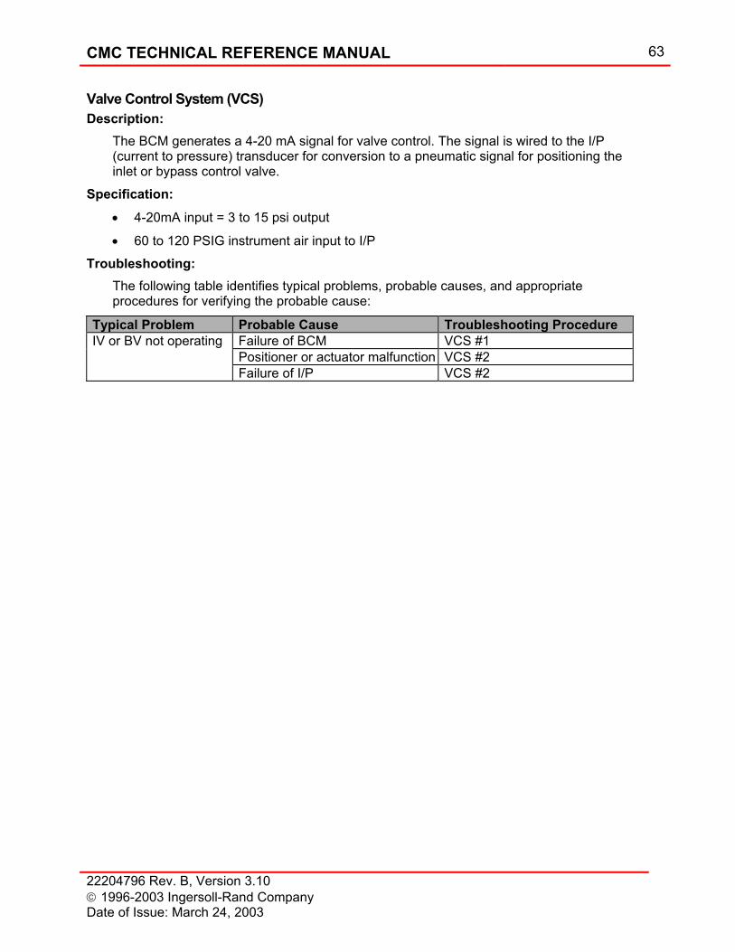
CMC TECHNICAL REFERENCE MANUAL 63
22204796 Rev. B, Version 3.10 1996-2003 Ingersoll-Rand Company Date of Issue: March 24, 2003
Valve Control System (VCS) Description:
The BCM generates a 4-20 mA signal for valve control. The signal is wired to the I/P (current to pressure) transducer for conversion to a pneumatic signal for positioning the inlet or bypass control valve.
Specification: • 4-20mA input = 3 to 15 psi output
• 60 to 120 PSIG instrument air input to I/P
Troubleshooting: The following table identifies typical problems, probable causes, and appropriate procedures for verifying the probable cause:
Typical Problem Probable Cause Troubleshooting Procedure IV or BV not operating Failure of BCM VCS #1 Positioner or actuator malfunction VCS #2 Failure of I/P VCS #2
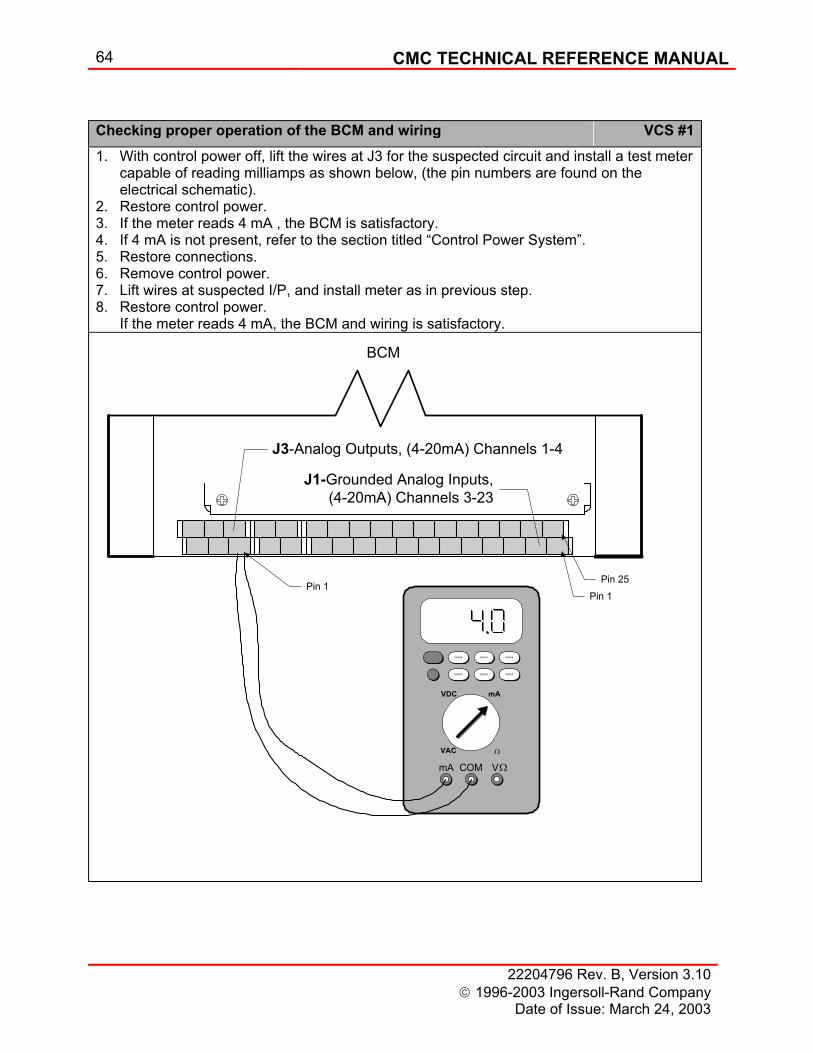
64 CMC TECHNICAL REFERENCE MANUAL
22204796 Rev. B, Version 3.10 1996-2003 Ingersoll-Rand Company
Date of Issue: March 24, 2003
Checking proper operation of the BCM and wiring VCS #11. With control power off, lift the wires at J3 for the suspected circuit and install a test meter
capable of reading milliamps as shown below, (the pin numbers are found on the electrical schematic).
2. Restore control power. 3. If the meter reads 4 mA , the BCM is satisfactory. 4. If 4 mA is not present, refer to the section titled “Control Power System”. 5. Restore connections. 6. Remove control power. 7. Lift wires at suspected I/P, and install meter as in previous step. 8. Restore control power. If the meter reads 4 mA, the BCM and wiring is satisfactory.
J3-Analog Outputs, (4-20mA) Channels 1-4
J1-Grounded Analog Inputs,(4-20mA) Channels 3-23
Pin 1Pin 25
BCM
Pin 1
VDC mA
VAC Ω
mA COM V
XXXXX XXXXX XXXXX
XXXXX XXXXX XXXXX
Ω
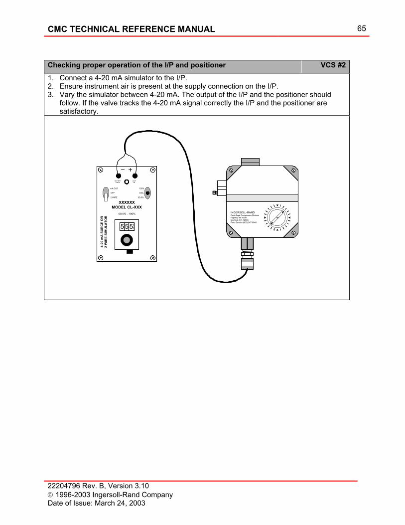
CMC TECHNICAL REFERENCE MANUAL 65
22204796 Rev. B, Version 3.10 1996-2003 Ingersoll-Rand Company Date of Issue: March 24, 2003
Checking proper operation of the I/P and positioner VCS #21. Connect a 4-20 mA simulator to the I/P. 2. Ensure instrument air is present at the supply connection on the I/P. 3. Vary the simulator between 4-20 mA. The output of the I/P and the positioner should
follow. If the valve tracks the 4-20 mA signal correctly the I/P and the positioner are satisfactory.
INGERSOLL-RANDCentrifugal Compressor DivisionHighway 45 SouthMayfield, KY. 42066Parts Service (800) 247-8640
mA OUT
2 WIRE
OFF
100%
00.0%
DIAL
BATTERYCHECK
LOOPON
XXXXXXMODEL CL-XXX
00.0% - 100%
555
4-20
mA
SU
RC
E O
R2
WIR
E SI
MU
LATO
R

66 CMC TECHNICAL REFERENCE MANUAL
22204796 Rev. B, Version 3.10 1996-2003 Ingersoll-Rand Company
Date of Issue: March 24, 2003
Pressure Monitoring System (PMS) Description:
A Pressure Transducer (PT) is used to convert pressure (psi) to a 4-20 mA signal for monitoring by the CMC.
Component specification: • 0-50 PSIG (344.75 kPa) range
• 0-200 PSIG (1379 kPa) range
• Power = 24 VDC
Troubleshooting: The following table identifies typical problems, probable causes, and appropriate procedures for verifying the probable cause:
Typical Problem Probable Cause Troubleshooting Procedure Zero OUI readout Open circuit/cable disconnected PMS #1, 2 Loss of power to transmitter PMS #1 Malfunctioning transmitter PMS #3, 4 Erratic OUI readout Loose wire/terminal/connector PMS #1,2 Incorrect OUI readout Any PMS #1, 2, 3, 4
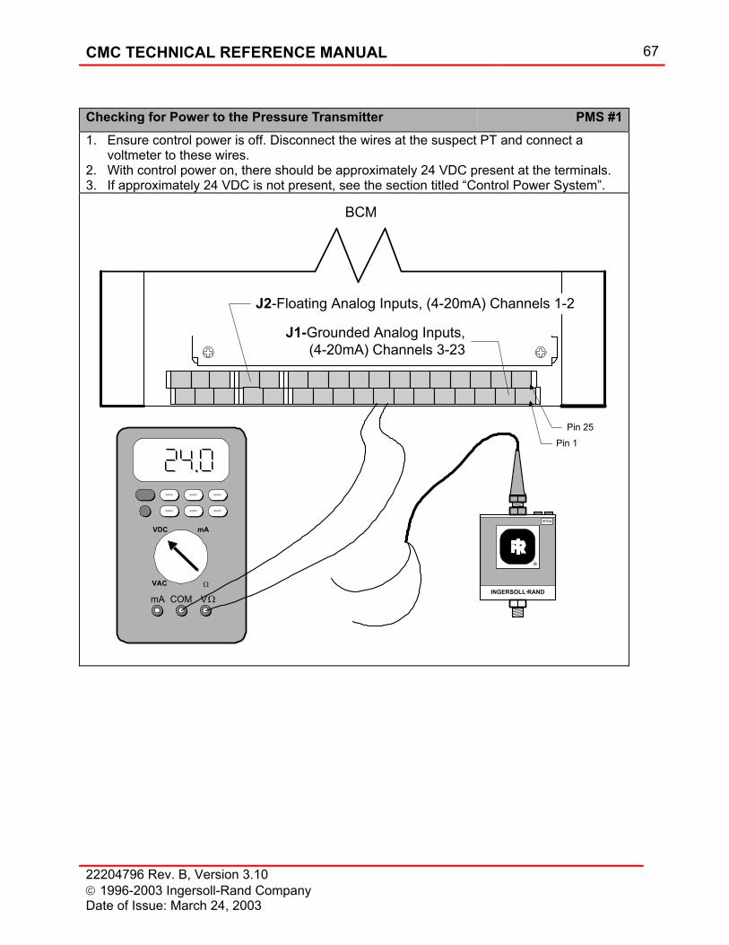
CMC TECHNICAL REFERENCE MANUAL 67
22204796 Rev. B, Version 3.10 1996-2003 Ingersoll-Rand Company Date of Issue: March 24, 2003
Checking for Power to the Pressure Transmitter PMS #11. Ensure control power is off. Disconnect the wires at the suspect PT and connect a
voltmeter to these wires. 2. With control power on, there should be approximately 24 VDC present at the terminals. 3. If approximately 24 VDC is not present, see the section titled “Control Power System”.
J2-Floating Analog Inputs, (4-20mA) Channels 1-2
J1-Grounded Analog Inputs,(4-20mA) Channels 3-23
Pin 1Pin 25
BCM
SPAN
®
INGERSOLL RAND
VDC mA
VAC Ω
mA COM V
XXXXX XXXXX XXXXX
XXXXX XXXXX XXXXX
Ω
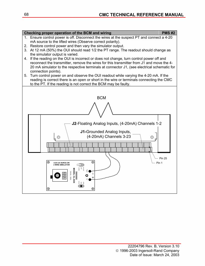
68 CMC TECHNICAL REFERENCE MANUAL
22204796 Rev. B, Version 3.10 1996-2003 Ingersoll-Rand Company
Date of Issue: March 24, 2003
Checking proper operation of the BCM and wiring PMS #21. Ensure control power is off. Disconnect the wires at the suspect PT and connect a 4-20
mA source to the lifted wires (Observe correct polarity). 2. Restore control power and then vary the simulator output. 3. At 12 mA (50%) the OUI should read 1/2 the PT range. The readout should change as
the simulator output is varied. 4. If the reading on the OUI is incorrect or does not change, turn control power off and
reconnect the transmitter, remove the wires for this transmitter from J1 and move the 4-20 mA simulator to the respective terminals at connector J1, (see electrical schematic for connection points).
5. Turn control power on and observe the OUI readout while varying the 4-20 mA. If the reading is correct there is an open or short in the wire or terminals connecting the CMC to the PT. If the reading is not correct the BCM may be faulty.
J2-Floating Analog Inputs, (4-20mA) Channels 1-2
J1-Grounded Analog Inputs,(4-20mA) Channels 3-23
Pin 1Pin 25
mA O
UT
2 WIR
E
OFF
100%
00.0%
DIAL
BATTERYCHECK
LOO
PO
N
XXXXXXM
OD
EL CL-XXX
00.0% - 100%
555
4-20 mA SURCE OR2 WIRE SIMULATOR
BCM
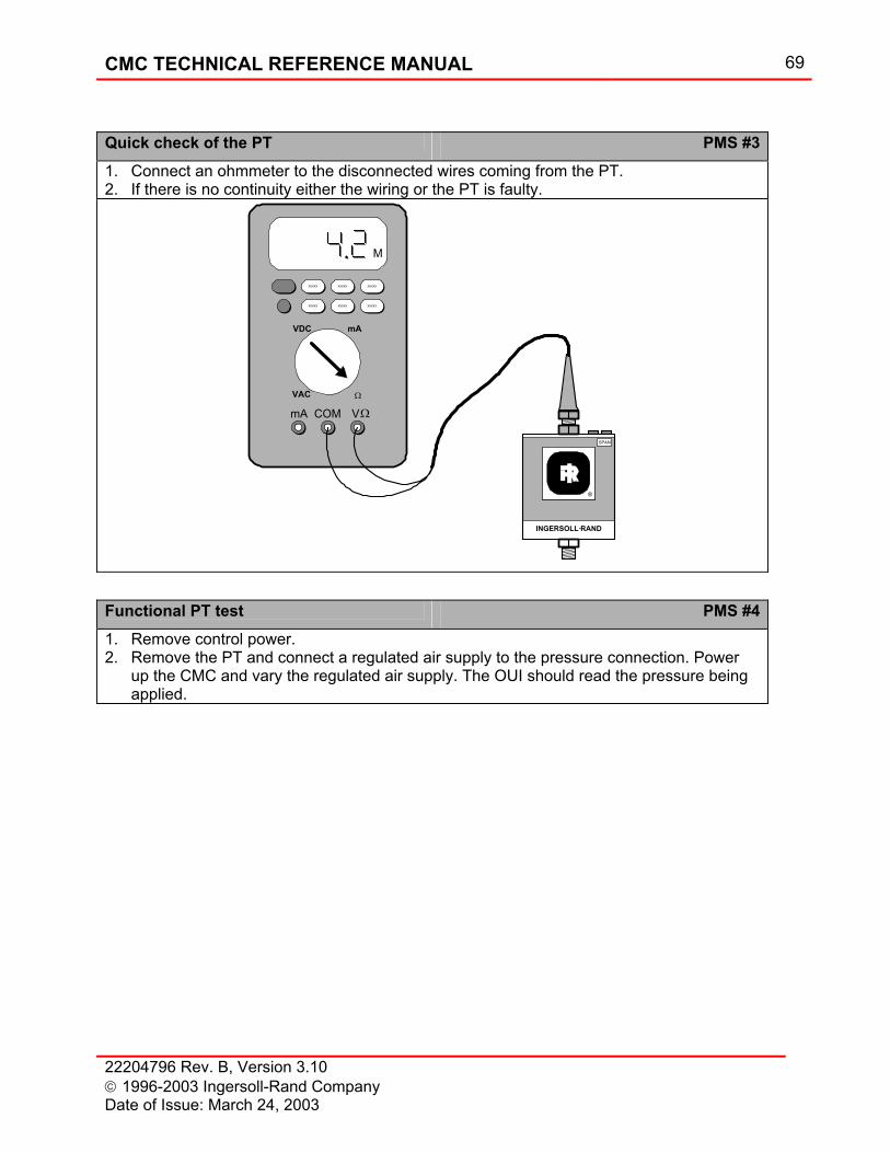
CMC TECHNICAL REFERENCE MANUAL 69
22204796 Rev. B, Version 3.10 1996-2003 Ingersoll-Rand Company Date of Issue: March 24, 2003
Quick check of the PT PMS #31. Connect an ohmmeter to the disconnected wires coming from the PT. 2. If there is no continuity either the wiring or the PT is faulty.
SPAN
®
INGERSOLL RAND
VDC mA
VAC Ω
mA COM V
XXXXX XXXXX XXXXX
XXXXX XXXXX XXXXX
Ω
M
Functional PT test PMS #41. Remove control power. 2. Remove the PT and connect a regulated air supply to the pressure connection. Power
up the CMC and vary the regulated air supply. The OUI should read the pressure being applied.
70 CMC TECHNICAL REFERENCE MANUAL
22204796 Rev. B, Version 3.10 1996-2003 Ingersoll-Rand Company
Date of Issue: March 24, 2003
Digital Input System (DIS) Description:
The digital input devices associated with the CMC are on/off devices that turn on or off the associated CMC digital input.
Typical digital device name and type: 1. Low seal air pressure (Pressure)
2. Low cooling water flow (Flapper)
3. Low oil level (Float)
4. High condensate level (Float)
5. Dirty inlet filter (Differential pressure)
6. Dirty oil filter (Differential pressure)
7. High motor temperature (Thermistor)
Troubleshooting: The following table identifies typical problems, probable causes, and appropriate procedures for verifying the probable cause:
Typical Problem Probable Cause Troubleshooting ProcedureFalse alarm or trip Faulty device DIS #1 Faulty wiring DIS #1
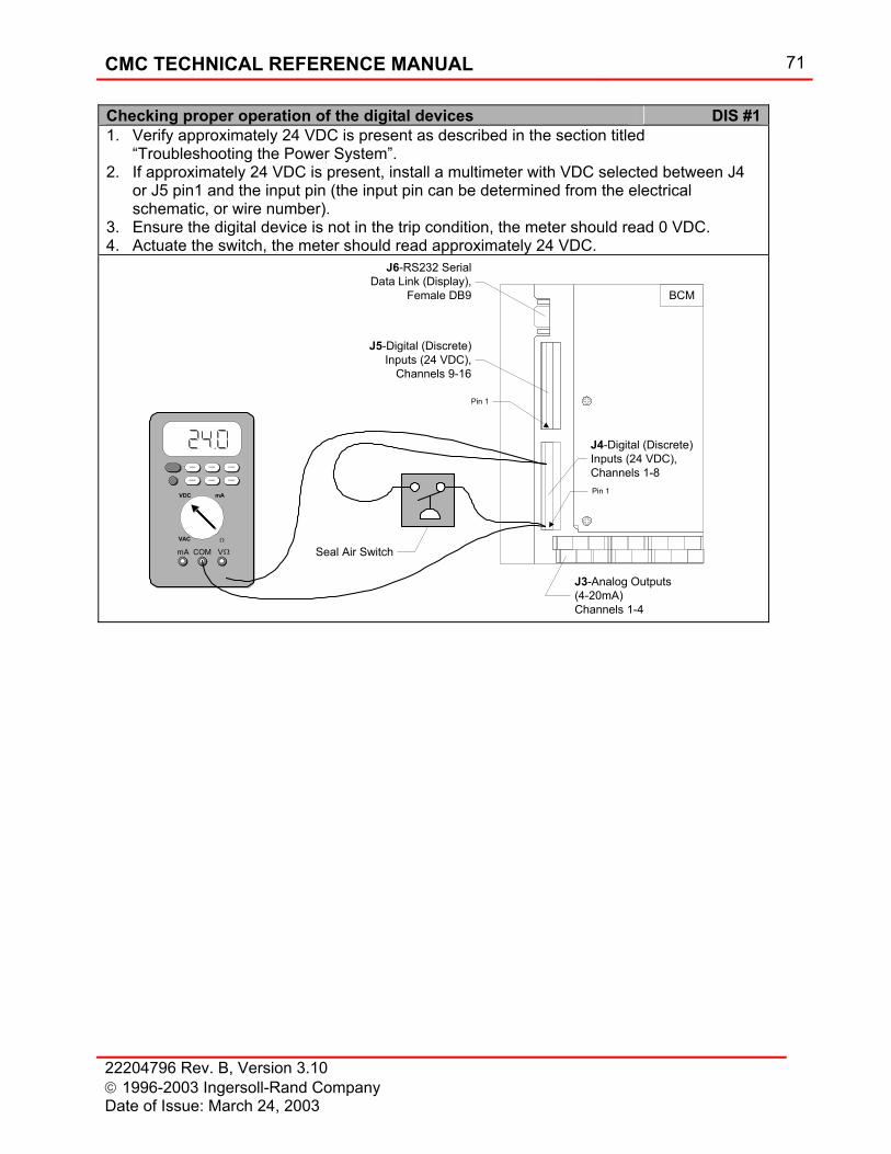
CMC TECHNICAL REFERENCE MANUAL 71
22204796 Rev. B, Version 3.10 1996-2003 Ingersoll-Rand Company Date of Issue: March 24, 2003
Checking proper operation of the digital devices DIS #11. Verify approximately 24 VDC is present as described in the section titled
“Troubleshooting the Power System”. 2. If approximately 24 VDC is present, install a multimeter with VDC selected between J4
or J5 pin1 and the input pin (the input pin can be determined from the electrical schematic, or wire number).
3. Ensure the digital device is not in the trip condition, the meter should read 0 VDC. 4. Actuate the switch, the meter should read approximately 24 VDC.
J3-Analog Outputs(4-20mA)Channels 1-4
Pin 1
Pin 1
J4-Digital (Discrete)Inputs (24 VDC),Channels 1-8
J5-Digital (Discrete)Inputs (24 VDC),
Channels 9-16
J6-RS232 SerialData Link (Display),
Female DB9 BCM
VDC mA
VAC Ω
mA COM V
XXXXX XXXXX XXXXX
XXXXX XXXXX XXXXX
Ω Seal Air Switch
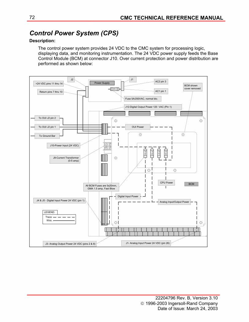
72 CMC TECHNICAL REFERENCE MANUAL
22204796 Rev. B, Version 3.10 1996-2003 Ingersoll-Rand Company
Date of Issue: March 24, 2003
Control Power System (CPS) Description:
The control power system provides 24 VDC to the CMC system for processing logic, displaying data, and monitoring instrumentation. The 24 VDC power supply feeds the Base Control Module (BCM) at connector J10. Over current protection and power distribution are performed as shown below:
F100
F101
F102
F103
All BCM Fuses are 5x20mm,GMA 1.5 amp, Fast Blow
Fuse 5A/250VAC, normal blo.
Power Supply
BCM
J2+24 VDC pins 11 thru 14
Return pins 7 thru 10
J1
AC1 pin 1
AC2 pin 3
J12-Digital Output Power 120 VAC (Pin 1)
J10-Power Input (24 VDC)
J9-Current Transformer(0-5 amp)
J4 & J5 - Digital Input Power 24 VDC (pin 1)
J3- Analog Output Power 24 VDC (pins 2 & 8) J1- Analog Input Power 24 VDC (pin 26)
Digital Input Power
Analog Input/Output Power
CPU Power
F1
LEGEND:
WireTrace
To OUI J2 pin 2
To OUI J2 pin 1
To Ground Bar
BCM showncover removed
OUI Power
CMC TECHNICAL REFERENCE MANUAL 73
22204796 Rev. B, Version 3.10 1996-2003 Ingersoll-Rand Company Date of Issue: March 24, 2003
Power Supply: • Input power: 85-132 VAC, or 180-264 VAC (auto-selecting input), 2.5A RMS max, 47-63
Hz.
• Output power: 24 VDC, 4.3 A maximum at 50 °C.
Troubleshooting: The following table identifies typical problems, probable causes, and appropriate procedures for verifying the probable cause:
Typical Problem Probable Cause Troubleshooting Procedure
All analog inputs are zero or negative on System Page No AC power CPS #1 No DC power CPS #2 No analog input
power CPS #5
OUI displays: “INGERSOLL-RAND Centrifugal Compressor Division”
No CPU power CPS #8
BCM problems CMCS #3 OUI is black No AC power CPS #1 No DC power CPS #2 No OUI power CPS #7 Event Log indicates all digital alarms and trips active No AC power CPS #1 No DC power CPS #2 No digital input
power CPS #3
All digital outputs not working No AC power CPS #1 No DC power CPS #2 No digital output
power CPS #4
All analog outputs not working No AC power CPS #1 No DC power CPS #2 No analog output
power CPS #6
No AC power CPS #11. Ensure control power is off. 2. Install a multimeter set for VAC between pins 1 and 3 at connector J1 on the power
supply. 3. Restore control power, the meter should read 120 VAC or 220 VAC depending upon
the rated supply power. The rated supply power can be verified from the electrical schematic.
74 CMC TECHNICAL REFERENCE MANUAL
22204796 Rev. B, Version 3.10 1996-2003 Ingersoll-Rand Company
Date of Issue: March 24, 2003
No DC power CPS #21. Ensure control power is off. 2. Install a multimeter set for VDC between pins 11-14 and 7-10 at connector J2 on the
power supply. 3. Restore control power, the meter should read approximately 24 VDC. If approximately
24 VDC is not present, check F1 on the power supply, if fuse is good, the power supply may be faulty.
4. Ensure control power is off. 5. Install a multimeter set for VDC between pins 1 and 2 at connector J10 on the BCM. 6. Restore control power, the meter should read approximately 24 VDC. If approximately
24 VDC is not present, check the wiring between the power supply and the BCM.
No digital input power CPS #31. Ensure control power is off. 2. Install a multimeter set for VDC between pin 1 at connector J4 on the BCM and the
ground bar. 3. Restore control power, the meter should read approximately 24 VDC. If approximately
24 VDC is not present, check F103 on the BCM, if F103 is good, check for DC power. No digital output power CPS #41. Ensure control power is off. 2. Install a multimeter set for VAC between pin 1 at connector J12 on the BCM and the
ground bar. 3. Restore control power, the meter should read 120 VAC.
No analog input power CPS #51. Ensure control power is off. 2. Install a multimeter set for VDC between pin 26 at connector J1 on the BCM and the
ground bar. 3. Restore control power, the meter should read approximately 24 VDC. If approximately
24 VDC is not present, check F102 on the BCM, if F102 is good, check for DC power. No analog output power CPS #61. Ensure control power is off. 2. Install a multimeter set for VDC between pin 2 at connector J3 on the BCM and the
ground bar. 3. Restore control power, the meter should read approximately 24 VDC. If approximately
24 VDC is not present, check F102 on the BCM, if F102 is good, check for DC power. No OUI power CPS #71. Ensure control power is off. 2. Install a multimeter set for VDC between pins 1 and 2 at connector J2 on the OUI. 3. Restore control power, the meter should read approximately 24 VCD. If approximately
24VDC is present, check F2 on the OUI. If F2 is good, go to next step. 4. Restore control power, the meter should read approximately 24 VDC. If approximately
24 VDC is not present, check F101 on the BCM, if F101 is good, check for DC power.

CMC TECHNICAL REFERENCE MANUAL 75
22204796 Rev. B, Version 3.10 1996-2003 Ingersoll-Rand Company Date of Issue: March 24, 2003
No CPU power CPS #81. Ensure control power is off. 2. Verify approximately 24 VDC is present at J10. 3. Check F100, if F100 is blown the BCM must be replaced, not the fuse. 4. If F100 is not blown, and the BCM is not functioning, the BCM must be replaced.
76 CMC TECHNICAL REFERENCE MANUAL
22204796 Rev. B, Version 3.10 1996-2003 Ingersoll-Rand Company
Date of Issue: March 24, 2003
Controller Problems Description:
The CMC System is generally comprised of a Base Control Module (BCM), Operator User Interface (OUI), and Power Supply (PS). There are few user serviceable components within the system; however, a brief understanding of the system will help in overall troubleshooting. All components require 24 VDC and rely on hardware and software to perform correctly, if the problem cannot be isolated to a power problem it is most likely a hardware or software problem, which will require Ingersoll-Rand support to correct.
Component Specification: • VDC power required
• Software required
Troubleshooting: The following table identifies typical problems, probable causes, and appropriate procedures for verifying the probable cause:
Typical Problem Probable Cause Troubleshooting Procedure
BCM fault suspected No power CMCS #4 OUI is dim Wrong contrast selected CMCS #1 Backlight failing CMCS #1 OUI is black No power CMCS #2 OUI displays “INGERSOLL-RAND Centrifugal Compressor Division”
Cable disconnected CMCS #3
OUI displays “Status XXH” Where XX is a specific number
Many Refer to Status Codes under System Information Section.
MODBUS communications problem No power CMCS #5 Many Refer to the UCM
Section.
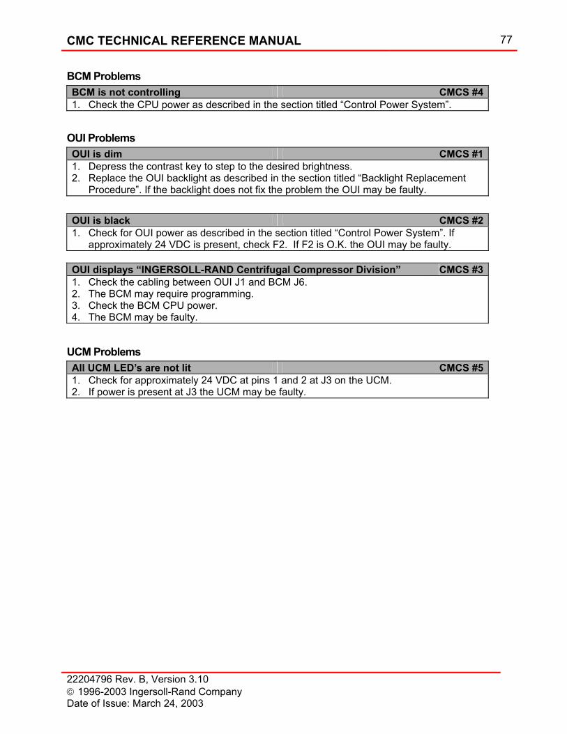
CMC TECHNICAL REFERENCE MANUAL 77
22204796 Rev. B, Version 3.10 1996-2003 Ingersoll-Rand Company Date of Issue: March 24, 2003
BCM Problems BCM is not controlling CMCS #41. Check the CPU power as described in the section titled “Control Power System”.
OUI Problems OUI is dim CMCS #11. Depress the contrast key to step to the desired brightness. 2. Replace the OUI backlight as described in the section titled “Backlight Replacement
Procedure”. If the backlight does not fix the problem the OUI may be faulty.
OUI is black CMCS #21. Check for OUI power as described in the section titled “Control Power System”. If
approximately 24 VDC is present, check F2. If F2 is O.K. the OUI may be faulty. OUI displays “INGERSOLL-RAND Centrifugal Compressor Division” CMCS #31. Check the cabling between OUI J1 and BCM J6. 2. The BCM may require programming. 3. Check the BCM CPU power. 4. The BCM may be faulty.
UCM Problems All UCM LED’s are not lit CMCS #51. Check for approximately 24 VDC at pins 1 and 2 at J3 on the UCM. 2. If power is present at J3 the UCM may be faulty.
78 CMC TECHNICAL REFERENCE MANUAL
22204796 Rev. B, Version 3.10 1996-2003 Ingersoll-Rand Company
Date of Issue: March 24, 2003
Options This section details the various standard options that are available for the CMC. Some of the options listed are provided standard on some models, and will be indicated as such.
Enclosures The CMC has three panel enclosures available; NEMA 12 (IP 64), which is standard, and optional NEMA 4 (IP 65) and NEMA 4X (IP 65). The panel is machine mounted. All electrical devices are mounted and wired where practical.
NEMA 12 (IP 64) NEMA 12 is the standard enclosure for all compressors with CMC panels. NEMA defines this rating as "... intended for indoor use primarily to provide a degree of protection against dust, falling dirt, and dripping non-corrosive liquids. They shall meet drip, dust, and rust-resistance design tests. They are not intended to provide protection against conditions such as internal condensation.” Typically this type of enclosure is applied for most indoor applications.
Cooling Fan The cooling fan is supplied on all standard CMC enclosures, where a wye-delta motor starter is present, the Control Electrical Package is included, or the ambient temperature exceeds 40°C keeps the internal temperature below the maximum operating temperature allowed. This action effectively extends the operating life of the control components. A filter and gasket are added to attain a NEMA 12 rating.
NEMA 4 (IP 65) This optional enclosure type is applied for most outdoor applications. Indoor applications that are subject to hose washing would also apply to this standard. NEMA defines this rating as "... intended for indoor and outdoor use primarily to provide a degree of protection against windblown dust and rain, splashing water, and hose directed water; and to be undamaged by the formation of ice on the enclosure. They shall meet hose down, external icing, and rust-resistance design tests. They are not intended to provide protection against conditions such as internal condensation or internal icing." The standard panel enclosure is replaced with a new box that meets the above requirements. The User Terminal vinyl overlay and sealing bezel is door mounted and allows direct interface with the environment. NEMA 4 rated lights, switches and buttons are mounted directly through the panel door. A panel space heater and Vortex Tube Cooler are added to accommodate changes in ambient temperatures.
NEMA 4X (IP 65) Also an optional enclosure type that should be applied in the same type of NEMA 4 applications within corrosive environments. The basic difference between NEMA 4 and NEMA 4X is that the panel enclosure is constructed with stainless steel.
CMC TECHNICAL REFERENCE MANUAL 79
22204796 Rev. B, Version 3.10 1996-2003 Ingersoll-Rand Company Date of Issue: March 24, 2003
Space Heater Required for NEMA 4 and NEMA 4X panels to protect the panel from internal condensation. This option should also be used with NEMA 12 for unheated building applications.
Vortex Tube Cooler This panel cooler is required on NEMA 4 and NEMA 4X enclosures to maintain the operating temperature below the maximum. An adjustable thermostat is provided to open and close a solenoid operated valve from the instrument air header in the panel. The cooler works by converting filtered compressed air into a hot air stream and cold air stream. The hot air stream is vented external to the enclosure and the cold air stream is directed into the enclosure.
Type Z Purge The CMC requires a Type Z Purge when the customer environment is Division 2. A Type Z Purge reduces the classification within an enclosure from Division 2 too non-hazardous. When provided, a NEMA 4 or NEMA 4X enclosure is required. Hand valve selectable quick and slow purges, with flow meters are provided to regulate the amount of gas entering the panel. A differential pressure switch is wired to a light on the front of the panel to indicate if there is a loss of purge gas. A relief valve is installed to prevent over-pressurization and a warning label, text below, is affixed to the front of the panel.
WARNING
Enclosure shall not be opened unless the area is known to be non-hazardous or unless all devices within the enclosure have been de-energized. Power shall not be restored after the enclosure has been opened until combustible dusts have been removed and the enclosure re-pressurized.
Fused Control Power Disconnect As a safety precaution, this option removes power from the panel before the door is opened. By turning the rotary door handle, the panel power is terminated. If the disconnect is to include fuse size provisions for the main motor starter, additional information is required. The disconnect would have to be mounted external to the panel enclosure. The short circuit capacity, maximum ground fault, motor full load amps, motor locked rotor amps and motor voltage must be known to size the disconnect properly. Pricing varies depending upon the size, amp rating of the fuse, which is required for protection.
NOTE
This option does not make fuse size provisions for the main motor starter.

80 CMC TECHNICAL REFERENCE MANUAL
22204796 Rev. B, Version 3.10 1996-2003 Ingersoll-Rand Company
Date of Issue: March 24, 2003
Control Electrical Package The Control Electrical Package consists of a Control Transformer, Prelube Pump Starter, Oil Heater Contactor(s) and Transient Voltage Surge Suppressor. This option allows the customer to bring a single source of electrical power to the compressor to run all of the compressor package accessories; thereby, making compressor installation easier.
Stage Data Package For monitoring of interstage pressure and temperatures, the Stage Data Package can be added. As standard, the CMC comes with temperature readout, alarm and trip for the next to last compression stage and compressor discharge pressure indication. When selected, each stage gets temperature and pressure measurements on the downstream side of each stage's cooler. For compressors without built-in aftercoolers, the last stage diffuser temperature is measured. Each temperature has readout, alarm and trip capability while the pressures are readout only.
Alarm Horn The optional alarm horn sounds any time there is an alarm or trip situation. The horn output will pulse for an alarm and remain constant for a trip. This allows the operator to distinguish between each fault type without viewing the OUI. The horn silence push-button is located on the CMC faceplate to silence any audible devices connected to the CMC board.
Running Unloaded Shutdown Timer The intent of this option is to save energy by shutting the compressor off during extended periods of unloaded operation. When the running unloaded shutdown timer is enabled with the RUNNING UNLOADED SHUTDOWN TIMER DISABLED/ENABLED selector switch, the auto-dual control mode should be selected, this provides for automatic unloading of the machine during periods of low demand.
Water Solenoid Post Run Timer This optional panel function is used to shut off water flow to the air and oil coolers after the compressor is stopped. It is accomplished by sending a signal to close the solenoid operated water valve(s).
Panel Mounted Wye-Delta Starter Main motor starter enclosed in the CMC panel. This feature allows the customer to wire the compressor from a single source; thereby, eliminating most electrical wiring and starter installation expense. These starters are available for compressors with motors up to 350 HP and 575 Volts.
N.O. Contact for Remote Indication of Common Alarm and Trip
A normally open contact for individual remote indication closes whenever an alarm or trip occurs. This allows a customer to have remote indication of compressor alarm, trip or both.
Power Regulating Constant Voltage Transformer If the electrical power supplied to the CMC varies more than ten percent, this transformer must be added to bring the voltage within the specification requirements.
CMC TECHNICAL REFERENCE MANUAL 81
22204796 Rev. B, Version 3.10 1996-2003 Ingersoll-Rand Company Date of Issue: March 24, 2003
Automatic Starting NOTE
Most electric motors are only rated for two cold starts or one hot start per hour. It is the operator’s responsibility not to exceed the electric motor’s limitation. The control system allows the compressor to be started when the compressor is ready, not the motor.
Remote start and stop through hard wiring to the compressor control panel, communicating through the MODBUS port via RS422/485, Auto-Hot Start and Auto-Cold Start are the four options for automatically starting and stopping with the CMC. With each of these options a REMOTE COMMUNICATIONS DISABLED/ENABLED or REMOTE FUNCTIONS DISABLED/ENABLED, selector switch is provided on the device plate with a REMOTE ENABLED light. Since each option performs basically the same function, only one should be purchased for a single CMC. The specific method selected depends upon the application.
Remote Start and Remote Stop – Hardwired When this option is purchased, two digital inputs are configured on the CMC Base Control Module, one for remote start and one for remote stop.
Remote Start Digital Input This input is driven by a momentary contact closure of at least 120 milliseconds. For the start to proceed, the panel power must be on, the compressor must be in the Ready state (all utilities must be running and permissive functions satisfied) and the REMOTE FUNCTIONS DISABLED/ENABLED selector switch is in ENABLED mode prior to energizing the input.
Remote Stop Digital Input This input is driven by a maintained contact closure. The remote stop input is always active; that is, the remote stop can be initiated regardless of the REMOTE FUNCTIONS DISABLED/ENABLED selector switch position.
Communications Remote starting and stopping can be accomplished through the MODBUS communication port in various ways. See the section on Communications that follows for these options. Again, panel power must be on, all utilities must be running and permissive functions satisfied in order for the start-up to proceed.
Auto-Hot Start Normally purchased in multiple compressor applications where backup air is required, this automatic starting option allows the compressor to be started when the system air pressure is below a user selected set point pressure. Panel power must be on, all utilities must be running, the AUTO HOT START DISABLED/ENABLED selector switch must be in the ENABLED position and all permissive functions satisfied in order for the start-up to proceed. Solenoid water valve(s) are provided for the intercooler(s) to reduce water consumption when the compressor is not running. A
82 CMC TECHNICAL REFERENCE MANUAL
22204796 Rev. B, Version 3.10 1996-2003 Ingersoll-Rand Company
Date of Issue: March 24, 2003
post run timer is also included in the Auto Hot Start logic to de-energize the water solenoid valves twenty minutes after a compressor stop or trip to allow the oil to cool.
Auto-Cold Start This option is very similar to Auto-Hot Start with the exception that the compressor starts with no initial panel power. An additional timer is added to simulate the start button being pressed and another timer is added to bypass the low oil temperature function on start-up. One additional solenoid valve is included for instrument air supply. The CONTROL POWER OFF/ON selector switch label is modified to CONTROL POWER LOCAL/OFF/COLD START. When in the COLD START position, the compressor is OFF and can be started through the Auto-Cold Start function. As a safety precaution, an optional strobe light can be provided to indicate that an automatic start is about to begin.
Remote 4-20 mA Pressure Setpoint When the REMOTE FUNCTIONS DISABLED/ENABLED selector switch is in the ENABLED position, the CMC will monitor the specified analog input for pressure setpoint. If this analog input’s value minus the Pressure Setpoint (from the display) is greater than or equal to the display’s Pressure Setpoint step value (default 0.1 psi), a remote setpoint change will be requested. This request will be initiated, as long as there are no analog input error faults for this channel, and the change made will rounded to the nearest step value (0.1) size. This methodology prevents the control system from chasing an ever-changing analog input value.
Ambient Control plus Parallel Valve Control Logic Ambient Control
This feature uses Polytropic Head (or just Head) as the MinLoad control variable. By using Head, a more conservative MinLoad setting can be established which contributes to energy efficiency. For additional information on Polytropic Head, see section under SURGE CONTROL / Control Methodology. Polytropic Head may be selected as the MinLoad control variable for Pressure Control (the standard process control for the CMC), or optional Flow Control. Polytropic Head may also be selected as the MinLoad control variable for Steam and Gas Turbine Driven and Diesel Driven Compressors.
Parallel Valve Control Logic This feature includes a number changes to control logic to improve valve transitions.
• One feature is improved State Transitions. The overall effect will be better response to system dynamics requiring state changes. An example of this is inlet valve throttling. When the machine is rapidly throttling from Loaded State to the MinLoad state, the inlet valve will transition to MinLoad before actually reaching the Minload setpoint. The valve transition offset is a function of the PID settings for the MinLoad and Loaded loops and the rate at which the process control variable is rising. By making this transition early, improved control response is achieved. In this case, undershoot of MinLoad would be decreased and overshoot of the process variable would be decreased relative to previous CMC releases.
• For installations with big, quick swings in load that get the check valve opened and closed frequently a new Discharge Pressure Regulation feature may be selected
CMC TECHNICAL REFERENCE MANUAL 83
22204796 Rev. B, Version 3.10 1996-2003 Ingersoll-Rand Company Date of Issue: March 24, 2003
to provide better pressure control. Previously these large changes required the MinLoad to be set more conservatively. Otherwise if the controller could not react fast enough the system would decay while closing the bypass valve. This new control loop will regulate compressor discharge pressure when the discharge check valve is closed. Adding this loop also eliminates windup of the bypass valve and allow for quicker reentry into the system. This feature requires configuration by an Ingersoll-Rand service technician.
• Typically, overshoot can occur when the system being regulated has a significant change in dynamic response and the PID parameters are not changed accordingly. For compressor control, this happens when the controller used the same bypass valve PID values for control regardless of the check valve state. One way to handle this is with the above Discharge Pressure Regulation feature previously described. If the installation does not warrant setting up Discharge Pressure Regulation, the Loading Ramp rate feature is used to accommodate this check valve complication. The Loading Ramp feature minimizes overshoot upon a load command.
• An additional feature called Unloading Interrupt is also a part of the CMC. The unloading state can now be interrupted by a load command and reload the machine without completely unloading it.
• Deadband on Control Variables is another feature of Parallel Valve Control Logic. This feature prevents valve oscillations when the Process Variable is steady state. Steady state valve oscillation is primarily a result of the control valve’s inability to position as finely as required by the PID control loop. A typical scenario would be when the CMC commands the valve to open 0.05% and the valve opens 0.1%. The valve now needs to close 0.05% but will likely close 0.1% causing the cycle to start over. This feature requires configuration by an Ingersoll-Rand service technician.
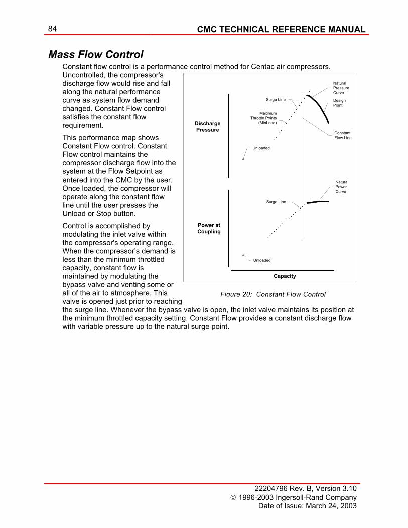
84 CMC TECHNICAL REFERENCE MANUAL
22204796 Rev. B, Version 3.10 1996-2003 Ingersoll-Rand Company
Date of Issue: March 24, 2003
Figure 20: Constant Flow Control
DischargePressure
Power atCoupling
Capacity
Surge Line
NaturalPressureCurve
DesignPoint
MaximumThrottle Points
(MinLoad)
ConstantFlow Line
Unloaded
NaturalPowerCurve
Surge Line
Unloaded
Mass Flow Control Constant flow control is a performance control method for Centac air compressors. Uncontrolled, the compressor's discharge flow would rise and fall along the natural performance curve as system flow demand changed. Constant Flow control satisfies the constant flow requirement. This performance map shows Constant Flow control. Constant Flow control maintains the compressor discharge flow into the system at the Flow Setpoint as entered into the CMC by the user. Once loaded, the compressor will operate along the constant flow line until the user presses the Unload or Stop button. Control is accomplished by modulating the inlet valve within the compressor's operating range. When the compressor’s demand is less than the minimum throttled capacity, constant flow is maintained by modulating the bypass valve and venting some or all of the air to atmosphere. This valve is opened just prior to reaching the surge line. Whenever the bypass valve is open, the inlet valve maintains its position at the minimum throttled capacity setting. Constant Flow provides a constant discharge flow with variable pressure up to the natural surge point.
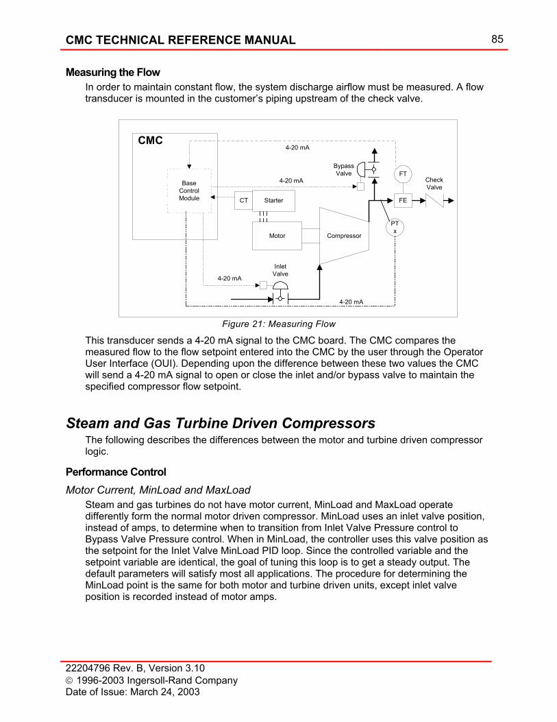
CMC TECHNICAL REFERENCE MANUAL 85
22204796 Rev. B, Version 3.10 1996-2003 Ingersoll-Rand Company Date of Issue: March 24, 2003
Measuring the Flow In order to maintain constant flow, the system discharge airflow must be measured. A flow transducer is mounted in the customer’s piping upstream of the check valve.
Figure 21: Measuring Flow
This transducer sends a 4-20 mA signal to the CMC board. The CMC compares the measured flow to the flow setpoint entered into the CMC by the user through the Operator User Interface (OUI). Depending upon the difference between these two values the CMC will send a 4-20 mA signal to open or close the inlet and/or bypass valve to maintain the specified compressor flow setpoint.
Steam and Gas Turbine Driven Compressors The following describes the differences between the motor and turbine driven compressor logic.
Performance Control Motor Current, MinLoad and MaxLoad
Steam and gas turbines do not have motor current, MinLoad and MaxLoad operate differently form the normal motor driven compressor. MinLoad uses an inlet valve position, instead of amps, to determine when to transition from Inlet Valve Pressure control to Bypass Valve Pressure control. When in MinLoad, the controller uses this valve position as the setpoint for the Inlet Valve MinLoad PID loop. Since the controlled variable and the setpoint variable are identical, the goal of tuning this loop is to get a steady output. The default parameters will satisfy most all applications. The procedure for determining the MinLoad point is the same for both motor and turbine driven units, except inlet valve position is recorded instead of motor amps.
CompressorMotor
StarterCT
BypassValve
InletValve
CheckValveBase
ControlModule
FT
4-20 mA
4-20 mA
CMC4-20 mA
FE
PTx
4-20 mA
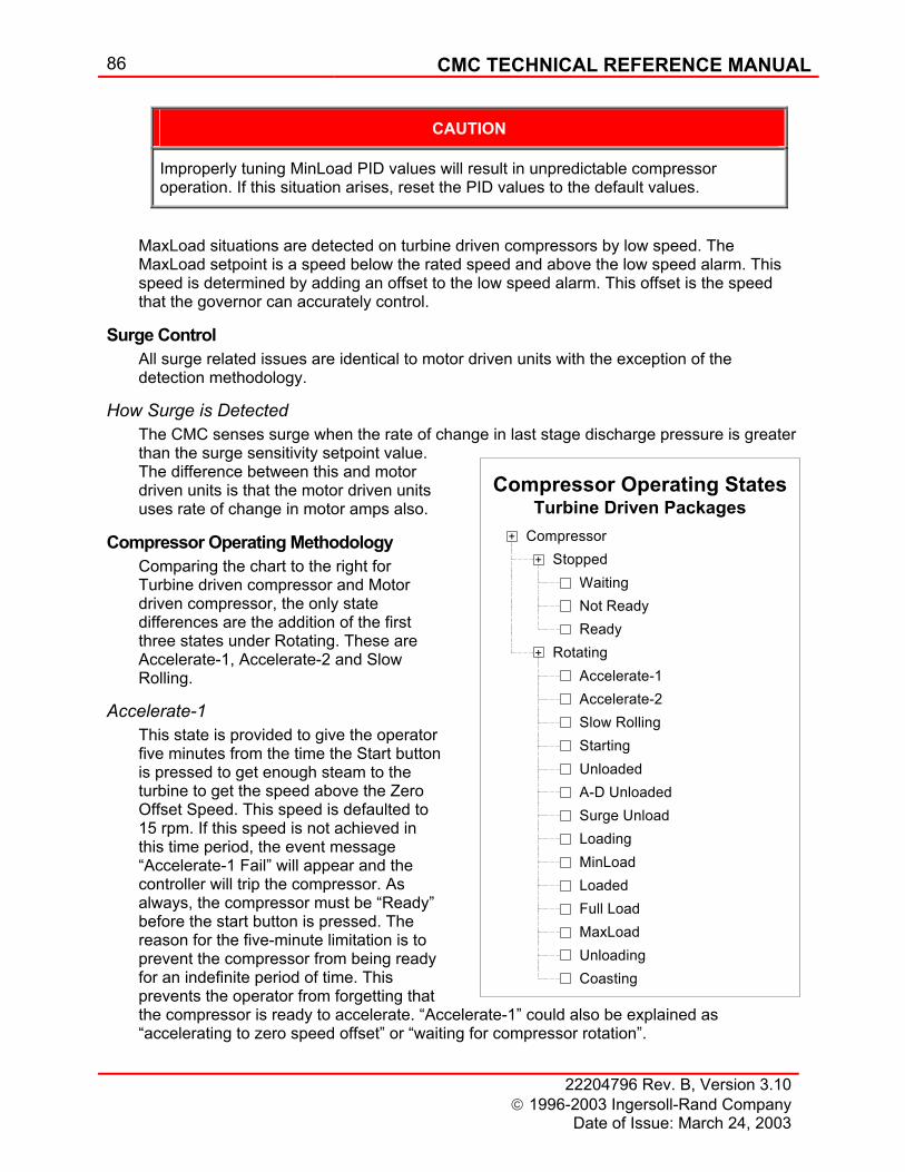
86 CMC TECHNICAL REFERENCE MANUAL
22204796 Rev. B, Version 3.10 1996-2003 Ingersoll-Rand Company
Date of Issue: March 24, 2003
Compressor Operating StatesTurbine Driven Packages
Stopped+
WaitingNot ReadyReady
Compressor+
+ Rotating
Starting
Accelerate-1Accelerate-2Slow Rolling
Loading
Unloaded
MinLoadLoadedFull LoadMaxLoad
A-D UnloadedSurge Unload
UnloadingCoasting
CAUTION
Improperly tuning MinLoad PID values will result in unpredictable compressor operation. If this situation arises, reset the PID values to the default values.
MaxLoad situations are detected on turbine driven compressors by low speed. The MaxLoad setpoint is a speed below the rated speed and above the low speed alarm. This speed is determined by adding an offset to the low speed alarm. This offset is the speed that the governor can accurately control.
Surge Control All surge related issues are identical to motor driven units with the exception of the detection methodology.
How Surge is Detected The CMC senses surge when the rate of change in last stage discharge pressure is greater than the surge sensitivity setpoint value. The difference between this and motor driven units is that the motor driven units uses rate of change in motor amps also.
Compressor Operating Methodology Comparing the chart to the right for Turbine driven compressor and Motor driven compressor, the only state differences are the addition of the first three states under Rotating. These are Accelerate-1, Accelerate-2 and Slow Rolling.
Accelerate-1 This state is provided to give the operator five minutes from the time the Start button is pressed to get enough steam to the turbine to get the speed above the Zero Offset Speed. This speed is defaulted to 15 rpm. If this speed is not achieved in this time period, the event message “Accelerate-1 Fail” will appear and the controller will trip the compressor. As always, the compressor must be “Ready” before the start button is pressed. The reason for the five-minute limitation is to prevent the compressor from being ready for an indefinite period of time. This prevents the operator from forgetting that the compressor is ready to accelerate. “Accelerate-1” could also be explained as “accelerating to zero speed offset” or “waiting for compressor rotation”.
CMC TECHNICAL REFERENCE MANUAL 87
22204796 Rev. B, Version 3.10 1996-2003 Ingersoll-Rand Company Date of Issue: March 24, 2003
Accelerate-2 After the transition to Accelerate-1 is complete, this state is initiated when rotation is detected and the turbine has not reached the low trip speed. This state may be bypassed if the turbine accelerates very quickly. Once in this state, a sixty (60) second timer is initiated. If the speed does not get to the minimum slow roll speed within this time period, the event message “Accelerate-2 Fail” will appear and the controller will trip the package. This state is limited sixty (60) seconds to prevent bearing damage from rolling the compressor at too low a speed. The bearing design requires a minimum speed to form the oil film thickness required for proper bearing operation. “Accelerate-2” could also be explained as “accelerating to minimum slow roll speed”.
Slow Rolling After the transition to Accelerate-2 is complete, this state is entered after the previous sixty-second timer has elapsed and the speed is less than the low trip speed. The compressor can operate in this “Slow Rolling” state indefinitely. While in this state, if the speed drops below the minimum slow roll speed, the event message “Slow Roll Fail” will appear and the controller will trip the compressor. If at any time during “Slow Rolling” the speed exceeds the maximum slow roll speed, the compressor will transition to “Starting”. The Starting state for turbine driven compressors is the same as for motor driven compressors.
Quick Start Turbines Quick Start turbines may skip “Accelerate-2” and “Slow Rolling” or just “Slow Rolling” because of the acceleration characteristics. The acceleration sequence depends upon the acceleration characteristics for a given turbine.
Operator User Interface (OUI) Status Bar
Motor driven compressors have an optional Compressor Status Field for Start Disabled. This field is standard for turbine driven compressors and it means that the turbine trip and throttle valve limit switch has not been made.
System Folder Replacing “Motor Current “with” Compressor Speed” on Page 1 is the only modification to this folder.
Info Folder The events “Starter Failure” and ”Loss of Motor Current have been deleted from the possible event list. The following events have been added.
88 CMC TECHNICAL REFERENCE MANUAL
22204796 Rev. B, Version 3.10 1996-2003 Ingersoll-Rand Company
Date of Issue: March 24, 2003
Possible Events List
Event Name Description Accelerate-1 Fail The zero offset speed has not been achieved before the end of the five-minute timer. Accelerate-2 Fail The minimum slow roll speed has not been achieved before the end of the one-minute timer. Driver Trip The trip and throttle valve limit switch has been latched, then unlatched. Governor Common Trip The governor has tripped. High Speed Alarm The indicated speed is greater than or equal to the High Speed Alarm setting. High Speed Trip The indicated speed is greater than or equal to the High Speed Trip setting. Illegal Rotation Rotation has been detected when in “Stopped”. Low Speed Alarm The indicated speed is less than or equal to the Low Speed Alarm setting. Low Speed Trip The indicated speed is less than or equal to the Low Speed Trip setting. Slow Rolling Fail The minimum slow roll speed was not maintained during “Slow Roll”. Starting Fail The low trip speed was not achieved before the end of the Starting Timer. TTV Switch Fault The trip and throttle valve (TTV) limit switch is made when the (TTV) solenoid is de-energized.
Settings Folder
For Page 2, Anti-Surge and Driver Over-Load Protection … 1. “MaxLoad (HLL), amps” is replaced with “MaxLoad (HLL), rpm”. 2. “User Setpoint (TL), amps” is replaced with “User Setpoint (TL), IV Pos %”. 3. “Control Setpoint, amps” is replaced with “Control Setpoint, IV Pos %”. 4. “Surge Index Increment, amps” is replaced with “Surge Index Increment, IV Pos %”.
For Page 5, Miscellaneous 1. “CT Ratio” is removed. 2. “Motor Failure Trip Enable” checkbox is removed.
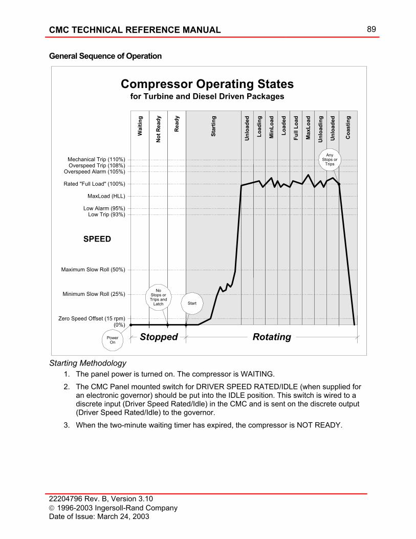
CMC TECHNICAL REFERENCE MANUAL 89
22204796 Rev. B, Version 3.10 1996-2003 Ingersoll-Rand Company Date of Issue: March 24, 2003
General Sequence of Operation
Starting Methodology 1. The panel power is turned on. The compressor is WAITING. 2. The CMC Panel mounted switch for DRIVER SPEED RATED/IDLE (when supplied for
an electronic governor) should be put into the IDLE position. This switch is wired to a discrete input (Driver Speed Rated/Idle) in the CMC and is sent on the discrete output (Driver Speed Rated/Idle) to the governor.
3. When the two-minute waiting timer has expired, the compressor is NOT READY.
Unl
oade
d
Coa
stin
g
Star
ting
Load
ing
Load
ed
Min
Load
Full
Load
Max
Load
Unl
oadi
ng
Unl
oade
dPower
On
Zero Speed Offset (15 rpm)
Minimum Slow Roll (25%)
Maximum Slow Roll (50%)
Low Alarm (95%)
MaxLoad (HLL)
Low Trip (93%)
Rated "Full Load" (100%)
Overspeed Alarm (105%)Overspeed Trip (108%)Mechanical Trip (110%)
(0%)
SPEED
RotatingStopped
Compressor Operating Statesfor Turbine and Diesel Driven Packages
Not
Rea
dy
Read
y
Wai
ting
AnyStops or
Trips
Start
NoStops orTrips and
Latch
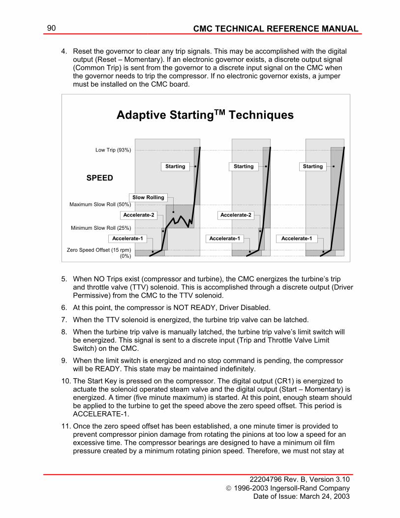
90 CMC TECHNICAL REFERENCE MANUAL
22204796 Rev. B, Version 3.10 1996-2003 Ingersoll-Rand Company
Date of Issue: March 24, 2003
4. Reset the governor to clear any trip signals. This may be accomplished with the digital output (Reset – Momentary). If an electronic governor exists, a discrete output signal (Common Trip) is sent from the governor to a discrete input signal on the CMC when the governor needs to trip the compressor. If no electronic governor exists, a jumper must be installed on the CMC board.
5. When NO Trips exist (compressor and turbine), the CMC energizes the turbine’s trip
and throttle valve (TTV) solenoid. This is accomplished through a discrete output (Driver Permissive) from the CMC to the TTV solenoid.
6. At this point, the compressor is NOT READY, Driver Disabled. 7. When the TTV solenoid is energized, the turbine trip valve can be latched. 8. When the turbine trip valve is manually latched, the turbine trip valve’s limit switch will
be energized. This signal is sent to a discrete input (Trip and Throttle Valve Limit Switch) on the CMC.
9. When the limit switch is energized and no stop command is pending, the compressor will be READY. This state may be maintained indefinitely.
10. The Start Key is pressed on the compressor. The digital output (CR1) is energized to actuate the solenoid operated steam valve and the digital output (Start – Momentary) is energized. A timer (five minute maximum) is started. At this point, enough steam should be applied to the turbine to get the speed above the zero speed offset. This period is ACCELERATE-1.
11. Once the zero speed offset has been established, a one minute timer is provided to prevent compressor pinion damage from rotating the pinions at too low a speed for an excessive time. The compressor bearings are designed to have a minimum oil film pressure created by a minimum rotating pinion speed. Therefore, we must not stay at
Accelerate-1
Accelerate-2
Slow Rolling
Starting
Accelerate-1
Accelerate-2
Starting
Accelerate-1
Starting
Adaptive StartingTM Techniques
Zero Speed Offset (15 rpm)
Minimum Slow Roll (25%)
Maximum Slow Roll (50%)
Low Trip (93%)
(0%)
SPEED
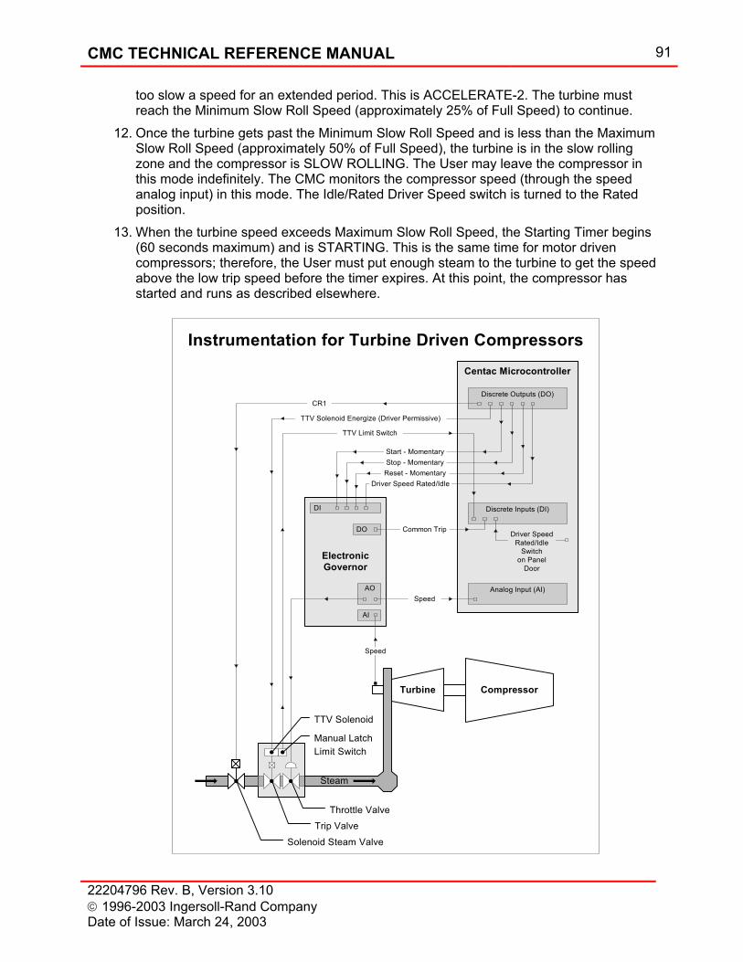
CMC TECHNICAL REFERENCE MANUAL 91
22204796 Rev. B, Version 3.10 1996-2003 Ingersoll-Rand Company Date of Issue: March 24, 2003
too slow a speed for an extended period. This is ACCELERATE-2. The turbine must reach the Minimum Slow Roll Speed (approximately 25% of Full Speed) to continue.
12. Once the turbine gets past the Minimum Slow Roll Speed and is less than the Maximum Slow Roll Speed (approximately 50% of Full Speed), the turbine is in the slow rolling zone and the compressor is SLOW ROLLING. The User may leave the compressor in this mode indefinitely. The CMC monitors the compressor speed (through the speed analog input) in this mode. The Idle/Rated Driver Speed switch is turned to the Rated position.
13. When the turbine speed exceeds Maximum Slow Roll Speed, the Starting Timer begins (60 seconds maximum) and is STARTING. This is the same time for motor driven compressors; therefore, the User must put enough steam to the turbine to get the speed above the low trip speed before the timer expires. At this point, the compressor has started and runs as described elsewhere.
Instrumentation for Turbine Driven CompressorsCentac Microcontroller
Turbine Compressor
ElectronicGovernor
Discrete Outputs (DO)
Discrete Inputs (DI)
TTV Solenoid Energize (Driver Permissive)
CR1
Analog Input (AI)
TTV Limit Switch
Driver SpeedRated/Idle
Switchon Panel
Door
Common Trip
Start - MomentaryStop - Momentary
Reset - Momentary
Speed
DI
AO
AI
Solenoid Steam Valve
Throttle Valve
TTV Solenoid
Manual LatchLimit Switch
Steam
Trip Valve
DO
Speed
Driver Speed Rated/Idle

92 CMC TECHNICAL REFERENCE MANUAL
22204796 Rev. B, Version 3.10 1996-2003 Ingersoll-Rand Company
Date of Issue: March 24, 2003
Diesel Driven Compressors Diesel driven compressors have similar characteristics as the turbine driven compressors. The differences are…
1. “Idle/Rated Driver Speed” discrete input and discrete output are eliminated. 2. “Start – Momentary”, “Stop – Momentary” and “Reset – Momentary” discrete outputs
are eliminated. 3. “Driver Permissive” discrete output is wired to the “Trip and Throttle Valve Limit
Switch” discrete input.
CMC TECHNICAL REFERENCE MANUAL 93
22204796 Rev. B, Version 3.10 1996-2003 Ingersoll-Rand Company Date of Issue: March 24, 2003
Communication Customers may want to communicate to the CMC control systems for remote compressor control and monitoring. This communication capability provides for flexibility in the customer's compressed air operation through remote start and stop, data gathering for preventative maintenance, and incorporation into plant-wide control system. The major avenue for communicating with the CMC is via MODBUS protocol over an RS422/485 hardware link. This requires hardware for the control panel, and a communications device with the appropriate driver software to perform the desired panel functions. The RS422/485 interface can communicate with any serial device that has an RS422 or RS485 port. The customer or his representative must write system software to suit his individual needs for remote control and monitoring. Since the customer writes this interface, the system can be as flexible as the customer desires.
Human Machine Interface (HMI) Systems Air System Controller (ASC) and Air System Manager (ASM) are software packages available for compressors with CMC panels. ASC and ASM are graphical integration software specifically developed for air compressor systems. Both provide energy management through load sharing and reduction of air bypass by using a minimum amount of energy to meet the system demand. The primary goal of both systems is to maintain stable system pressure, to integrate, monitor and control the compressed air system. ASM is the integration of compressor control software in an off-the-shelf Supervisor Control and Data Acquisition (SCADA) package that is available from various manufacturers. The ASM provides more custom features than does ASC. Both ASC and ASM provide a window into the compressor room by making the raw data from compressors and other equipment available to plant operators and managers in formats that are easy to understand. Implementing the CMC in any HMI system may require additional hardware and/or software upgrade.
Direct CMC Communications with RS422/485 For the descriptions that follow, a serial device can be a Personal Computer (PC), Programmable Logic Controller (PLC), Distributed Control System (DCS) or any other device that can transmit, receive and interpret an RS422/485 formatted signal over a hardware link. In the descriptions that follow, the PC and PLC serial devices are not specific to manufacturers or operating systems. There are many ways of interfacing to CMC control systems through an RS422/485 port. Most of the following methodologies are currently available; but please be aware, other possible configurations can exist. All RS422/485 interfaces require custom interface software and custom application software. The interface software allows a specific serial device and operating system to transmit, receive and interpret data from a CMC control system. The application software tells the CMC control system what to do; for example, start compressor when ready, stop compressor after midnight and retrieve the current data and save to a disk file.
94 CMC TECHNICAL REFERENCE MANUAL
22204796 Rev. B, Version 3.10 1996-2003 Ingersoll-Rand Company
Date of Issue: March 24, 2003
Currently there are hundreds of different serial devices using different operating systems and languages in the industrial equipment world. Therefore, the practicality of having an interface for many systems is limited. Custom interfaces must be written as required by the hardware and operating system used. The capabilities of the hardware and the imagination of the developer only limit the application software. For example, one developer may have two compressors. In this application the developer wants a screen to display the compressor interstage pressure and temperatures for both machines with various other compressor data. A second developer has five compressors. He also wants to display the same data, but this time for all five machines. The only way this is done is through changing the application software (custom modification). The developer may write functions to read and display data, log that data to some magnetic media for storage, change compressor set points, sequence the compressors for efficient operation and network additional devices, such as pumps, dryers, etc., into the system. All of these functions require specially written application software for the intended use.
The CMC-MODBUS Interface Introduction
The CMC can communicate with other devices over a variety of communications standards. Supported standards, or protocols, include RS-232, IRBUS (Ingersoll-Rand Proprietary), and Modicon’s MODBUS. The built-in ports on the CMC’s optional Universal Communication Adapters access communications. The CMC-MODBUS Interface defines the message structure that a CMC uses to exist on a MODBUS network. This interface will allow the MODBUS network to gather information and control the compressor.
NOTE
Unless specified otherwise, numerical values (such as addresses, codes, or data) are expressed as decimal values in the text of this section. They are expressed as hexadecimal values in the message fields of the examples.
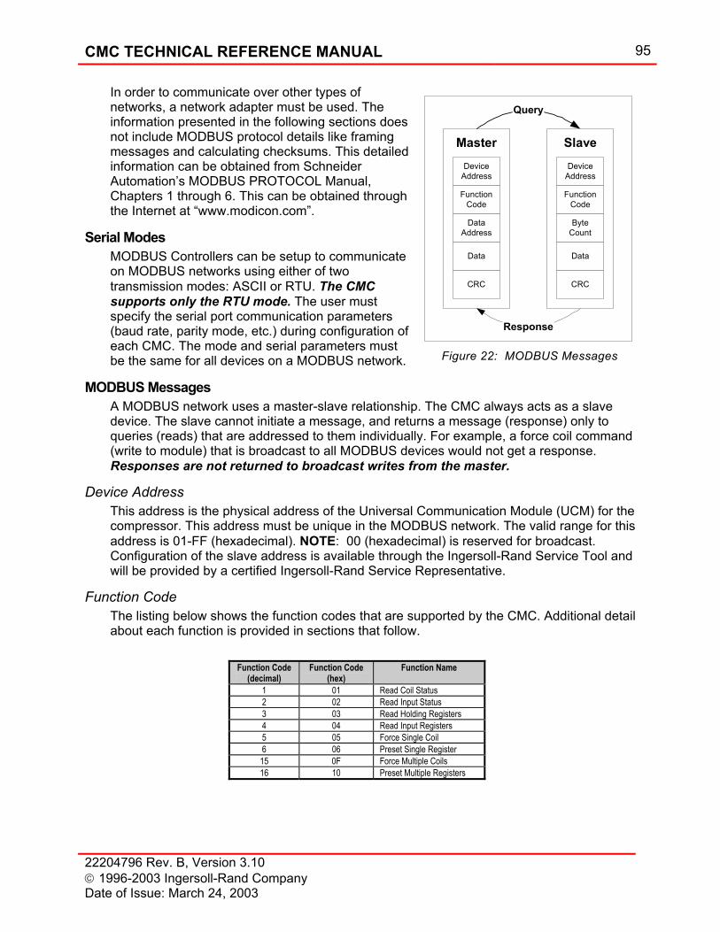
CMC TECHNICAL REFERENCE MANUAL 95
22204796 Rev. B, Version 3.10 1996-2003 Ingersoll-Rand Company Date of Issue: March 24, 2003
In order to communicate over other types of networks, a network adapter must be used. The information presented in the following sections does not include MODBUS protocol details like framing messages and calculating checksums. This detailed information can be obtained from Schneider Automation’s MODBUS PROTOCOL Manual, Chapters 1 through 6. This can be obtained through the Internet at “www.modicon.com”.
Serial Modes MODBUS Controllers can be setup to communicate on MODBUS networks using either of two transmission modes: ASCII or RTU. The CMC supports only the RTU mode. The user must specify the serial port communication parameters (baud rate, parity mode, etc.) during configuration of each CMC. The mode and serial parameters must be the same for all devices on a MODBUS network.
MODBUS Messages A MODBUS network uses a master-slave relationship. The CMC always acts as a slave device. The slave cannot initiate a message, and returns a message (response) only to queries (reads) that are addressed to them individually. For example, a force coil command (write to module) that is broadcast to all MODBUS devices would not get a response. Responses are not returned to broadcast writes from the master.
Device Address This address is the physical address of the Universal Communication Module (UCM) for the compressor. This address must be unique in the MODBUS network. The valid range for this address is 01-FF (hexadecimal). NOTE: 00 (hexadecimal) is reserved for broadcast. Configuration of the slave address is available through the Ingersoll-Rand Service Tool and will be provided by a certified Ingersoll-Rand Service Representative.
Function Code The listing below shows the function codes that are supported by the CMC. Additional detail about each function is provided in sections that follow.
DeviceAddress
FunctionCode
DataAddress
Data
CRC
Master
Response
Query
DeviceAddress
FunctionCode
ByteCount
Data
CRC
Slave
Figure 22: MODBUS Messages
Function Code (decimal)
Function Code (hex)
Function Name
1 01 Read Coil Status 2 02 Read Input Status 3 03 Read Holding Registers 4 04 Read Input Registers 5 05 Force Single Coil 6 06 Preset Single Register 15 0F Force Multiple Coils 16 10 Preset Multiple Registers
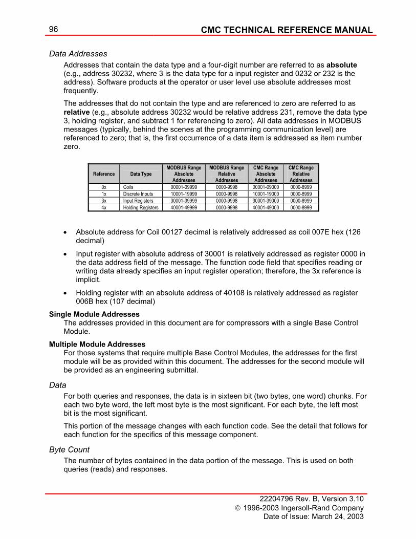
96 CMC TECHNICAL REFERENCE MANUAL
22204796 Rev. B, Version 3.10 1996-2003 Ingersoll-Rand Company
Date of Issue: March 24, 2003
Data Addresses Addresses that contain the data type and a four-digit number are referred to as absolute (e.g., address 30232, where 3 is the data type for a input register and 0232 or 232 is the address). Software products at the operator or user level use absolute addresses most frequently. The addresses that do not contain the type and are referenced to zero are referred to as relative (e.g., absolute address 30232 would be relative address 231, remove the data type 3, holding register, and subtract 1 for referencing to zero). All data addresses in MODBUS messages (typically, behind the scenes at the programming communication level) are referenced to zero; that is, the first occurrence of a data item is addressed as item number zero.
• Absolute address for Coil 00127 decimal is relatively addressed as coil 007E hex (126 decimal)
• Input register with absolute address of 30001 is relatively addressed as register 0000 in the data address field of the message. The function code field that specifies reading or writing data already specifies an input register operation; therefore, the 3x reference is implicit.
• Holding register with an absolute address of 40108 is relatively addressed as register 006B hex (107 decimal)
Single Module Addresses The addresses provided in this document are for compressors with a single Base Control Module.
Multiple Module Addresses For those systems that require multiple Base Control Modules, the addresses for the first module will be as provided within this document. The addresses for the second module will be provided as an engineering submittal.
Data For both queries and responses, the data is in sixteen bit (two bytes, one word) chunks. For each two byte word, the left most byte is the most significant. For each byte, the left most bit is the most significant. This portion of the message changes with each function code. See the detail that follows for each function for the specifics of this message component.
Byte Count The number of bytes contained in the data portion of the message. This is used on both queries (reads) and responses.
Reference
Data Type
MODBUS Range Absolute
Addresses
MODBUS Range Relative
Addresses
CMC Range Absolute
Addresses
CMC Range Relative
Addresses 0x Coils 00001-09999 0000-9998 00001-09000 0000-8999 1x Discrete Inputs 10001-19999 0000-9998 10001-19000 0000-8999 3x Input Registers 30001-39999 0000-9998 30001-39000 0000-8999 4x Holding Registers 40001-49999 0000-9998 40001-49000 0000-8999
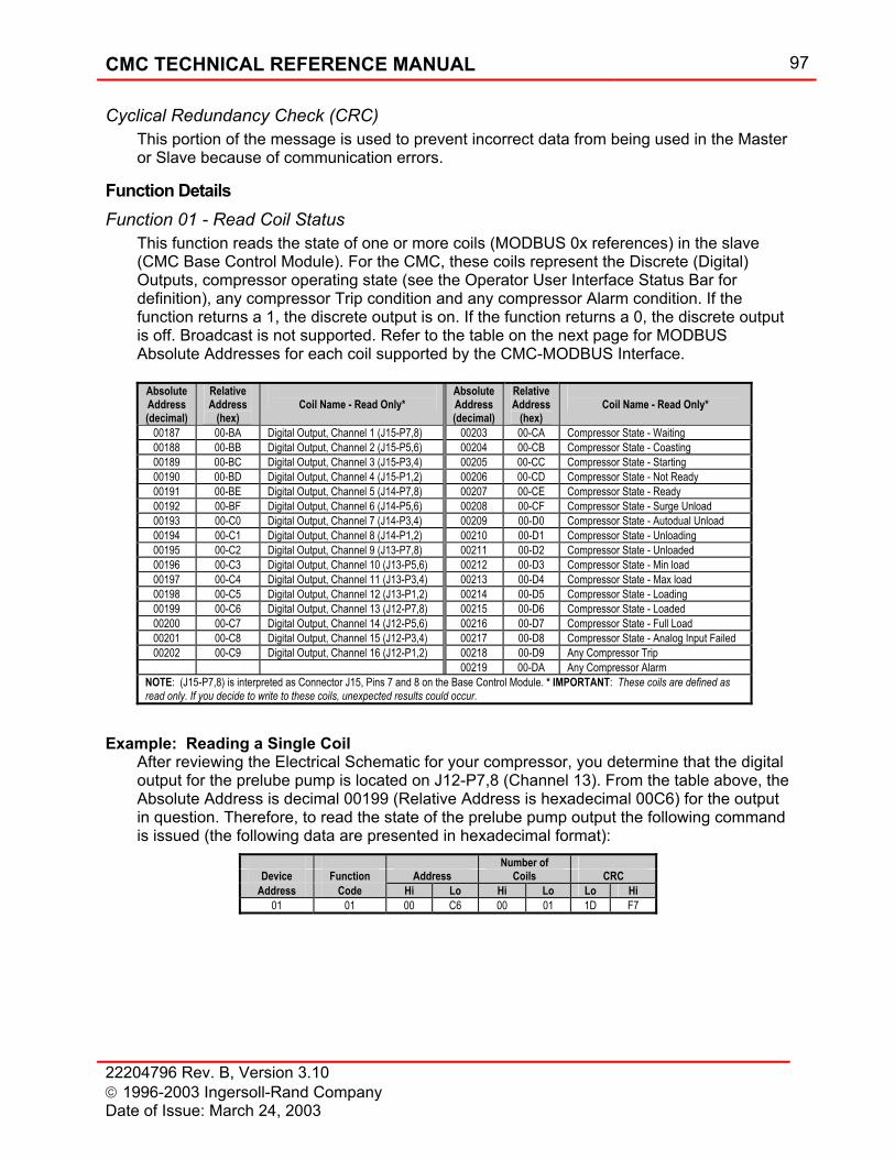
CMC TECHNICAL REFERENCE MANUAL 97
22204796 Rev. B, Version 3.10 1996-2003 Ingersoll-Rand Company Date of Issue: March 24, 2003
Cyclical Redundancy Check (CRC) This portion of the message is used to prevent incorrect data from being used in the Master or Slave because of communication errors.
Function Details Function 01 - Read Coil Status
This function reads the state of one or more coils (MODBUS 0x references) in the slave (CMC Base Control Module). For the CMC, these coils represent the Discrete (Digital) Outputs, compressor operating state (see the Operator User Interface Status Bar for definition), any compressor Trip condition and any compressor Alarm condition. If the function returns a 1, the discrete output is on. If the function returns a 0, the discrete output is off. Broadcast is not supported. Refer to the table on the next page for MODBUS Absolute Addresses for each coil supported by the CMC-MODBUS Interface.
Example: Reading a Single Coil After reviewing the Electrical Schematic for your compressor, you determine that the digital output for the prelube pump is located on J12-P7,8 (Channel 13). From the table above, the Absolute Address is decimal 00199 (Relative Address is hexadecimal 00C6) for the output in question. Therefore, to read the state of the prelube pump output the following command is issued (the following data are presented in hexadecimal format):
Absolute Address (decimal)
Relative Address
(hex)
Coil Name - Read Only*
Absolute Address (decimal)
Relative Address
(hex)
Coil Name - Read Only*
00187 00-BA Digital Output, Channel 1 (J15-P7,8) 00203 00-CA Compressor State - Waiting 00188 00-BB Digital Output, Channel 2 (J15-P5,6) 00204 00-CB Compressor State - Coasting 00189 00-BC Digital Output, Channel 3 (J15-P3,4) 00205 00-CC Compressor State - Starting 00190 00-BD Digital Output, Channel 4 (J15-P1,2) 00206 00-CD Compressor State - Not Ready 00191 00-BE Digital Output, Channel 5 (J14-P7,8) 00207 00-CE Compressor State - Ready 00192 00-BF Digital Output, Channel 6 (J14-P5,6) 00208 00-CF Compressor State - Surge Unload 00193 00-C0 Digital Output, Channel 7 (J14-P3,4) 00209 00-D0 Compressor State - Autodual Unload 00194 00-C1 Digital Output, Channel 8 (J14-P1,2) 00210 00-D1 Compressor State - Unloading 00195 00-C2 Digital Output, Channel 9 (J13-P7,8) 00211 00-D2 Compressor State - Unloaded 00196 00-C3 Digital Output, Channel 10 (J13-P5,6) 00212 00-D3 Compressor State - Min load 00197 00-C4 Digital Output, Channel 11 (J13-P3,4) 00213 00-D4 Compressor State - Max load 00198 00-C5 Digital Output, Channel 12 (J13-P1,2) 00214 00-D5 Compressor State - Loading 00199 00-C6 Digital Output, Channel 13 (J12-P7,8) 00215 00-D6 Compressor State - Loaded 00200 00-C7 Digital Output, Channel 14 (J12-P5,6) 00216 00-D7 Compressor State - Full Load 00201 00-C8 Digital Output, Channel 15 (J12-P3,4) 00217 00-D8 Compressor State - Analog Input Failed 00202 00-C9 Digital Output, Channel 16 (J12-P1,2) 00218 00-D9 Any Compressor Trip
00219 00-DA Any Compressor Alarm NOTE: (J15-P7,8) is interpreted as Connector J15, Pins 7 and 8 on the Base Control Module. * IMPORTANT: These coils are defined as read only. If you decide to write to these coils, unexpected results could occur.
Number of Device Function Address Coils CRC
Address Code Hi Lo Hi Lo Lo Hi 01 01 00 C6 00 01 1D F7
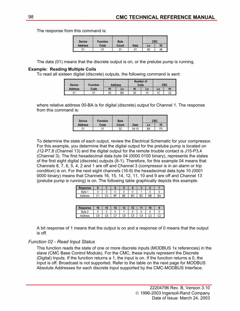
98 CMC TECHNICAL REFERENCE MANUAL
22204796 Rev. B, Version 3.10 1996-2003 Ingersoll-Rand Company
Date of Issue: March 24, 2003
The response from this command is:
The data (01) means that the discrete output is on, or the prelube pump is running.
Example: Reading Multiple Coils To read all sixteen digital (discrete) outputs, the following command is sent:
where relative address 00-BA is for digital (discrete) output for Channel 1. The response from this command is:
To determine the state of each output, review the Electrical Schematic for your compressor. For this example, you determine that the digital output for the prelube pump is located on J12-P7,8 (Channel 13) and the digital output for the remote trouble contact is J15-P3,4 (Channel 3). The first hexadecimal data byte 04 (0000 0100 binary), represents the states of the first eight digital (discrete) outputs (8-1). Therefore, for this example 04 means that Channels 8, 7, 6, 5, 4, 2 and 1 are off and Channel 3 (compressor is in an alarm or trip condition) is on. For the next eight channels (16-9) the hexadecimal data byte 10 (0001 0000 binary) means that Channels 16, 15, 14, 12, 11, 10 and 9 are off and Channel 13 (prelube pump is running) is on. The following table graphically depicts this example:
A bit response of 1 means that the output is on and a response of 0 means that the output is off.
Function 02 - Read Input Status This function reads the state of one or more discrete inputs (MODBUS 1x references) in the slave (CMC Base Control Module). For the CMC, these inputs represent the Discrete (Digital) Inputs. If the function returns a 1, the input is on. If the function returns a 0, the input is off. Broadcast is not supported. Refer to the table on the next page for MODBUS Absolute Addresses for each discrete input supported by the CMC-MODBUS Interface.
Device Function Byte CRC
Address Code Count Data Lo Hi 01 01 01 01 90 48
Number of Device Function Address Coils CRC
Address Code Hi Lo Hi Lo Lo Hi 01 01 00 BA 00 10 1C 23
Device Function Byte CRC
Address Code Count Data Lo Hi 01 01 02 04-10 BA F0
Response 8 7 6 5 4 3 2 1 Byte 1 0 0 0 0 0 1 0 0
Address C1 C0 BF BE BD BC BB BA Response 16 15 14 13 12 11 10 9
Byte 2 0 0 0 1 0 0 0 0 Address C9 C8 C7 C6 C5 C4 C3 C2
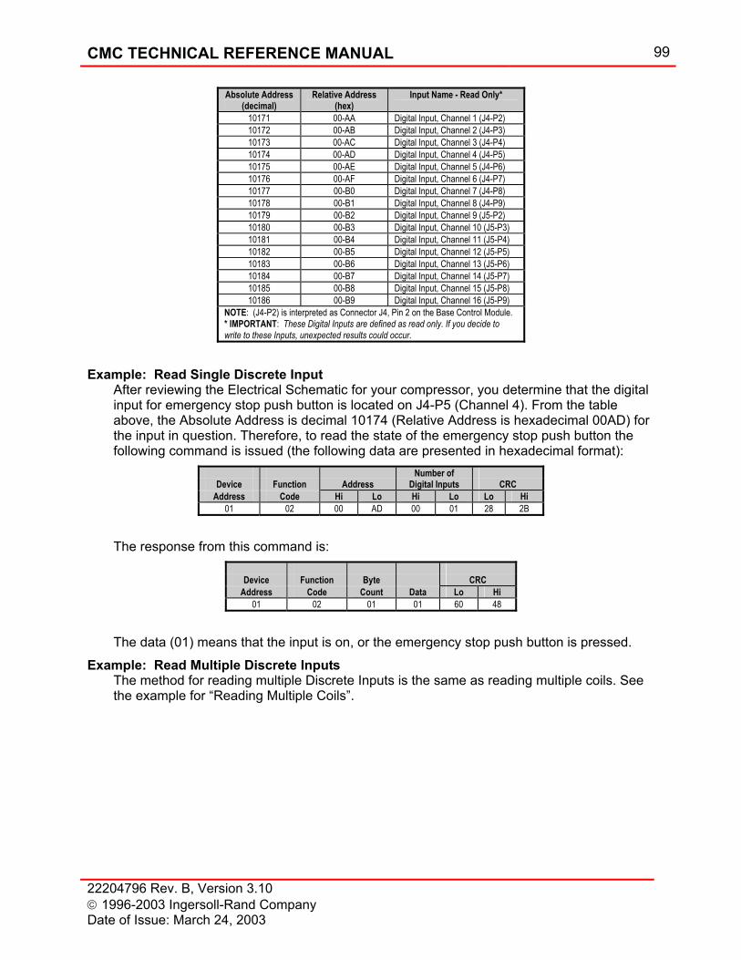
CMC TECHNICAL REFERENCE MANUAL 99
22204796 Rev. B, Version 3.10 1996-2003 Ingersoll-Rand Company Date of Issue: March 24, 2003
Example: Read Single Discrete Input After reviewing the Electrical Schematic for your compressor, you determine that the digital input for emergency stop push button is located on J4-P5 (Channel 4). From the table above, the Absolute Address is decimal 10174 (Relative Address is hexadecimal 00AD) for the input in question. Therefore, to read the state of the emergency stop push button the following command is issued (the following data are presented in hexadecimal format):
The response from this command is:
The data (01) means that the input is on, or the emergency stop push button is pressed.
Example: Read Multiple Discrete Inputs The method for reading multiple Discrete Inputs is the same as reading multiple coils. See the example for “Reading Multiple Coils”.
Absolute Address (decimal)
Relative Address (hex)
Input Name - Read Only*
10171 00-AA Digital Input, Channel 1 (J4-P2) 10172 00-AB Digital Input, Channel 2 (J4-P3) 10173 00-AC Digital Input, Channel 3 (J4-P4) 10174 00-AD Digital Input, Channel 4 (J4-P5) 10175 00-AE Digital Input, Channel 5 (J4-P6) 10176 00-AF Digital Input, Channel 6 (J4-P7) 10177 00-B0 Digital Input, Channel 7 (J4-P8) 10178 00-B1 Digital Input, Channel 8 (J4-P9) 10179 00-B2 Digital Input, Channel 9 (J5-P2) 10180 00-B3 Digital Input, Channel 10 (J5-P3) 10181 00-B4 Digital Input, Channel 11 (J5-P4) 10182 00-B5 Digital Input, Channel 12 (J5-P5) 10183 00-B6 Digital Input, Channel 13 (J5-P6) 10184 00-B7 Digital Input, Channel 14 (J5-P7) 10185 00-B8 Digital Input, Channel 15 (J5-P8) 10186 00-B9 Digital Input, Channel 16 (J5-P9)
NOTE: (J4-P2) is interpreted as Connector J4, Pin 2 on the Base Control Module. * IMPORTANT: These Digital Inputs are defined as read only. If you decide to write to these Inputs, unexpected results could occur.
Number of Device Function Address Digital Inputs CRC
Address Code Hi Lo Hi Lo Lo Hi 01 02 00 AD 00 01 28 2B
Device Function Byte CRC
Address Code Count Data Lo Hi 01 02 01 01 60 48

100 CMC TECHNICAL REFERENCE MANUAL
22204796 Rev. B, Version 3.10 1996-2003 Ingersoll-Rand Company
Date of Issue: March 24, 2003
Function 03 - Read Holding Registers Reads the binary content of holding registers (MODBUS 4x references) in the slave (CMC Base Control Module). For the CMC, these holding registers contain the Analog Output values and Analog Alarm and Trip Setpoint values for all CMC inputs and outputs. Broadcast is not supported. The CMC is primarily a 32-bit floating-point microprocessor controller. And, since MODBUS is designed to be a 16-bit system, the CMC supports two methods for determining the value for each holding register (This also applies to Input Registers.)
NOTE
Since MODBUS is a 16-bit system, the programmer must get two 16-bit numbers and combine them into one 32-bit floating-point number.
The first method uses two 16-bit integers to represent the integer and fraction part of the value. The second method uses one 32-bit IEEE floating point number. (NOTE: For those who would like to only get the 16-bit integer value, this will work well for most inputs; however, the CMC has some inputs, like vibration, that are typically less than one. Since the CMC has programmable analog and discrete inputs and outputs, the programmer must use the electrical schematic supplied with the contract to determine which function name and units of measure are associated with each input and output. Refer to the table below for MODBUS Absolute Addresses for each Holding Register supported by the CMC-MODBUS Interface.
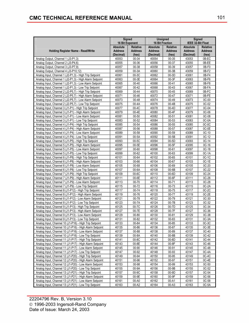
CMC TECHNICAL REFERENCE MANUAL 101
22204796 Rev. B, Version 3.10 1996-2003 Ingersoll-Rand Company Date of Issue: March 24, 2003
Signed 16 Bit Exponent
Unsigned 16 Bit Fraction
Signed IEEE 32-Bit Float
Holding Register Name - Read/Write
Absolute Address (Decimal)
Relative Address
(hex)
Absolute Address (Decimal)
Relative Address
(hex)
Absolute Address (Decimal)
Relative Address
(hex) Analog Output, Channel 1 (J3-P1,3) 40053 00-34 40054 00-35 43053 0B-EC Analog Output, Channel 2 (J3-P4,6) 40055 00-36 40056 00-37 43055 0B-EE Analog Output, Channel 3 (J3-P7,9) 40057 00-38 40058 00-39 43057 0B-F0 Analog Output, Channel 4 (J3-P10,12) 40059 00-3A 40060 00-3B 43059 0B-F2 Analog Input, Channel 1 (J2-P1,3) - High Trip Setpoint 40061 00-3C 40062 00-3D 43061 0B-F4 Analog Input, Channel 1 (J2-P1,3) - High Alarm Setpoint 40063 00-3E 40064 00-3F 43063 0B-F6 Analog Input, Channel 1 (J2-P1,3) - Low Alarm Setpoint 40065 00-40 40066 00-41 43065 0B-F8 Analog Input, Channel 1 (J2-P1,3) - Low Trip Setpoint 40067 00-42 40068 00-43 43067 0B-FA Analog Input, Channel 2 (J2-P5,7) - High Trip Setpoint 40069 00-44 40070 00-45 43069 0B-FC Analog Input, Channel 2 (J2-P5,7) - High Alarm Setpoint 40071 00-46 40072 00-47 43071 0B-FE Analog Input, Channel 2 (J2-P5,7) - Low Alarm Setpoint 40073 00-48 40074 00-49 43073 0C-00 Analog Input, Channel 2 (J2-P5,7) - Low Trip Setpoint 40075 00-4A 40076 00-4B 43075 0C-02 Analog Input, Channel 3 (J1-P1) - High Trip Setpoint 40077 00-4C 40078 00-4D 43077 0C-04 Analog Input, Channel 3 (J1-P1) - High Alarm Setpoint 40079 00-4E 40080 00-4F 43079 0C-06 Analog Input, Channel 3 (J1-P1) - Low Alarm Setpoint 40081 00-50 40082 00-51 43081 0C-08 Analog Input, Channel 3 (J1-P1) - Low Trip Setpoint 40083 00-52 40084 00-53 43083 0C-0A Analog Input, Channel 4 (J1-P4) - High Trip Setpoint 40085 00-54 40086 00-55 43085 0C-0C Analog Input, Channel 4 (J1-P4) - High Alarm Setpoint 40087 00-56 40088 00-57 43087 0C-0E Analog Input, Channel 4 (J1-P4) - Low Alarm Setpoint 40089 00-58 40090 00-59 43089 0C-10 Analog Input, Channel 4 (J1-P4) - Low Trip Setpoint 40091 00-5A 40092 00-5B 43091 0C-12 Analog Input, Channel 5 (J1-P5) - High Trip Setpoint 40093 00-5C 40094 00-5D 43093 0C-14 Analog Input, Channel 5 (J1-P5) - High Alarm Setpoint 40095 00-5E 40096 00-5F 43095 0C-16 Analog Input, Channel 5 (J1-P5) - Low Alarm Setpoint 40097 00-60 40098 00-61 43097 0C-18 Analog Input, Channel 5 (J1-P5) - Low Trip Setpoint 40099 00-62 40100 00-63 43099 0C-1A Analog Input, Channel 6 (J1-P8) - High Trip Setpoint 40101 00-64 40102 00-65 43101 0C-1C Analog Input, Channel 6 (J1-P8) - High Alarm Setpoint 40103 00-66 40104 00-67 43103 0C-1E Analog Input, Channel 6 (J1-P8) - Low Alarm Setpoint 40105 00-68 40106 00-69 43105 0C-20 Analog Input, Channel 6 (J1-P8) - Low Trip Setpoint 40107 00-6A 40108 00-6B 43107 0C-22 Analog Input, Channel 7 (J1-P9) - High Trip Setpoint 40109 00-6C 40110 00-6D 43109 0C-24 Analog Input, Channel 7 (J1-P9) - High Alarm Setpoint 40111 00-6E 40112 00-6F 43111 0C-26 Analog Input, Channel 7 (J1-P9) - Low Alarm Setpoint 40113 00-70 40114 00-71 43113 0C-28 Analog Input, Channel 7 (J1-P9) - Low Trip Setpoint 40115 00-72 40116 00-73 43115 0C-2A Analog Input, Channel 8 (J1-P12) - High Trip Setpoint 40117 00-74 40118 00-75 43117 0C-2C Analog Input, Channel 8 (J1-P12) - High Alarm Setpoint 40119 00-76 40120 00-77 43119 0C-2E Analog Input, Channel 8 (J1-P12) - Low Alarm Setpoint 40121 00-78 40122 00-79 43121 0C-30 Analog Input, Channel 8 (J1-P12) - Low Trip Setpoint 40123 00-7A 40124 00-7B 43123 0C-32 Analog Input, Channel 9 (J1-P13) - High Trip Setpoint 40125 00-7C 40126 00-7D 43125 0C-34 Analog Input, Channel 9 (J1-P13) - High Alarm Setpoint 40127 00-7E 40128 00-7F 43127 0C-36 Analog Input, Channel 9 (J1-P13) - Low Alarm Setpoint 40129 00-80 40130 00-81 43129 0C-38 Analog Input, Channel 9 (J1-P13) - Low Trip Setpoint 40131 00-82 40132 00-83 43131 0C-3A Analog Input, Channel 10 (J1-P16) - High Trip Setpoint 40133 00-84 40134 00-85 43133 0C-3C Analog Input, Channel 10 (J1-P16) - High Alarm Setpoint 40135 00-86 40136 00-87 43135 0C-3E Analog Input, Channel 10 (J1-P16) - Low Alarm Setpoint 40137 00-88 40138 00-89 43137 0C-40 Analog Input, Channel 10 (J1-P16) - Low Trip Setpoint 40139 00-8A 40140 00-8B 43139 0C-42 Analog Input, Channel 11 (J1-P17) - High Trip Setpoint 40141 00-8C 40142 00-8D 43141 0C-44 Analog Input, Channel 11 (J1-P17) - High Alarm Setpoint 40143 00-8E 40144 00-8F 43143 0C-46 Analog Input, Channel 11 (J1-P17) - Low Alarm Setpoint 40145 00-90 40146 00-91 43145 0C-48 Analog Input, Channel 11 (J1-P17) - Low Trip Setpoint 40147 00-92 40148 00-93 43147 0C-4A Analog Input, Channel 12 (J1-P20) - High Trip Setpoint 40149 00-94 40150 00-95 43149 0C-4C Analog Input, Channel 12 (J1-P20) - High Alarm Setpoint 40151 00-96 40152 00-97 43151 0C-4E Analog Input, Channel 12 (J1-P20) - Low Alarm Setpoint 40153 00-98 40154 00-99 43153 0C-50 Analog Input, Channel 12 (J1-P20) - Low Trip Setpoint 40155 00-9A 40156 00-9B 43155 0C-52 Analog Input, Channel 13 (J1-P21) - High Trip Setpoint 40157 00-9C 40158 00-9D 43157 0C-54 Analog Input, Channel 13 (J1-P21) - High Alarm Setpoint 40159 00-9E 40160 00-9F 43159 0C-56 Analog Input, Channel 13 (J1-P21) - Low Alarm Setpoint 40161 00-A0 40162 00-A1 43161 0C-58 Analog Input, Channel 13 (J1-P21) - Low Trip Setpoint 40163 00-A2 40164 00-A3 43163 0C-5A
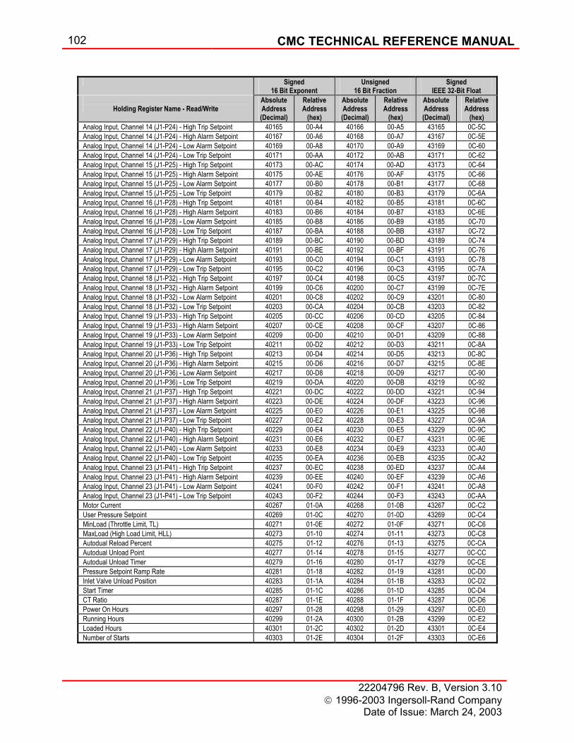
102 CMC TECHNICAL REFERENCE MANUAL
22204796 Rev. B, Version 3.10 1996-2003 Ingersoll-Rand Company
Date of Issue: March 24, 2003
Signed
16 Bit Exponent Unsigned
16 Bit Fraction Signed
IEEE 32-Bit Float
Holding Register Name - Read/Write Absolute Address (Decimal)
Relative Address
(hex)
Absolute Address (Decimal)
Relative Address
(hex)
Absolute Address (Decimal)
Relative Address
(hex) Analog Input, Channel 14 (J1-P24) - High Trip Setpoint 40165 00-A4 40166 00-A5 43165 0C-5C Analog Input, Channel 14 (J1-P24) - High Alarm Setpoint 40167 00-A6 40168 00-A7 43167 0C-5E Analog Input, Channel 14 (J1-P24) - Low Alarm Setpoint 40169 00-A8 40170 00-A9 43169 0C-60 Analog Input, Channel 14 (J1-P24) - Low Trip Setpoint 40171 00-AA 40172 00-AB 43171 0C-62 Analog Input, Channel 15 (J1-P25) - High Trip Setpoint 40173 00-AC 40174 00-AD 43173 0C-64 Analog Input, Channel 15 (J1-P25) - High Alarm Setpoint 40175 00-AE 40176 00-AF 43175 0C-66 Analog Input, Channel 15 (J1-P25) - Low Alarm Setpoint 40177 00-B0 40178 00-B1 43177 0C-68 Analog Input, Channel 15 (J1-P25) - Low Trip Setpoint 40179 00-B2 40180 00-B3 43179 0C-6A Analog Input, Channel 16 (J1-P28) - High Trip Setpoint 40181 00-B4 40182 00-B5 43181 0C-6C Analog Input, Channel 16 (J1-P28) - High Alarm Setpoint 40183 00-B6 40184 00-B7 43183 0C-6E Analog Input, Channel 16 (J1-P28) - Low Alarm Setpoint 40185 00-B8 40186 00-B9 43185 0C-70 Analog Input, Channel 16 (J1-P28) - Low Trip Setpoint 40187 00-BA 40188 00-BB 43187 0C-72 Analog Input, Channel 17 (J1-P29) - High Trip Setpoint 40189 00-BC 40190 00-BD 43189 0C-74 Analog Input, Channel 17 (J1-P29) - High Alarm Setpoint 40191 00-BE 40192 00-BF 43191 0C-76 Analog Input, Channel 17 (J1-P29) - Low Alarm Setpoint 40193 00-C0 40194 00-C1 43193 0C-78 Analog Input, Channel 17 (J1-P29) - Low Trip Setpoint 40195 00-C2 40196 00-C3 43195 0C-7A Analog Input, Channel 18 (J1-P32) - High Trip Setpoint 40197 00-C4 40198 00-C5 43197 0C-7C Analog Input, Channel 18 (J1-P32) - High Alarm Setpoint 40199 00-C6 40200 00-C7 43199 0C-7E Analog Input, Channel 18 (J1-P32) - Low Alarm Setpoint 40201 00-C8 40202 00-C9 43201 0C-80 Analog Input, Channel 18 (J1-P32) - Low Trip Setpoint 40203 00-CA 40204 00-CB 43203 0C-82 Analog Input, Channel 19 (J1-P33) - High Trip Setpoint 40205 00-CC 40206 00-CD 43205 0C-84 Analog Input, Channel 19 (J1-P33) - High Alarm Setpoint 40207 00-CE 40208 00-CF 43207 0C-86 Analog Input, Channel 19 (J1-P33) - Low Alarm Setpoint 40209 00-D0 40210 00-D1 43209 0C-88 Analog Input, Channel 19 (J1-P33) - Low Trip Setpoint 40211 00-D2 40212 00-D3 43211 0C-8A Analog Input, Channel 20 (J1-P36) - High Trip Setpoint 40213 00-D4 40214 00-D5 43213 0C-8C Analog Input, Channel 20 (J1-P36) - High Alarm Setpoint 40215 00-D6 40216 00-D7 43215 0C-8E Analog Input, Channel 20 (J1-P36) - Low Alarm Setpoint 40217 00-D8 40218 00-D9 43217 0C-90 Analog Input, Channel 20 (J1-P36) - Low Trip Setpoint 40219 00-DA 40220 00-DB 43219 0C-92 Analog Input, Channel 21 (J1-P37) - High Trip Setpoint 40221 00-DC 40222 00-DD 43221 0C-94 Analog Input, Channel 21 (J1-P37) - High Alarm Setpoint 40223 00-DE 40224 00-DF 43223 0C-96 Analog Input, Channel 21 (J1-P37) - Low Alarm Setpoint 40225 00-E0 40226 00-E1 43225 0C-98 Analog Input, Channel 21 (J1-P37) - Low Trip Setpoint 40227 00-E2 40228 00-E3 43227 0C-9A Analog Input, Channel 22 (J1-P40) - High Trip Setpoint 40229 00-E4 40230 00-E5 43229 0C-9C Analog Input, Channel 22 (J1-P40) - High Alarm Setpoint 40231 00-E6 40232 00-E7 43231 0C-9E Analog Input, Channel 22 (J1-P40) - Low Alarm Setpoint 40233 00-E8 40234 00-E9 43233 0C-A0 Analog Input, Channel 22 (J1-P40) - Low Trip Setpoint 40235 00-EA 40236 00-EB 43235 0C-A2 Analog Input, Channel 23 (J1-P41) - High Trip Setpoint 40237 00-EC 40238 00-ED 43237 0C-A4 Analog Input, Channel 23 (J1-P41) - High Alarm Setpoint 40239 00-EE 40240 00-EF 43239 0C-A6 Analog Input, Channel 23 (J1-P41) - Low Alarm Setpoint 40241 00-F0 40242 00-F1 43241 0C-A8 Analog Input, Channel 23 (J1-P41) - Low Trip Setpoint 40243 00-F2 40244 00-F3 43243 0C-AA Motor Current 40267 01-0A 40268 01-0B 43267 0C-C2 User Pressure Setpoint 40269 01-0C 40270 01-0D 43269 0C-C4 MinLoad (Throttle Limit, TL) 40271 01-0E 40272 01-0F 43271 0C-C6 MaxLoad (High Load Limit, HLL) 40273 01-10 40274 01-11 43273 0C-C8 Autodual Reload Percent 40275 01-12 40276 01-13 43275 0C-CA Autodual Unload Point 40277 01-14 40278 01-15 43277 0C-CC Autodual Unload Timer 40279 01-16 40280 01-17 43279 0C-CE Pressure Setpoint Ramp Rate 40281 01-18 40282 01-19 43281 0C-D0 Inlet Valve Unload Position 40283 01-1A 40284 01-1B 43283 0C-D2 Start Timer 40285 01-1C 40286 01-1D 43285 0C-D4 CT Ratio 40287 01-1E 40288 01-1F 43287 0C-D6 Power On Hours 40297 01-28 40298 01-29 43297 0C-E0 Running Hours 40299 01-2A 40300 01-2B 43299 0C-E2 Loaded Hours 40301 01-2C 40302 01-2D 43301 0C-E4 Number of Starts 40303 01-2E 40304 01-2F 43303 0C-E6
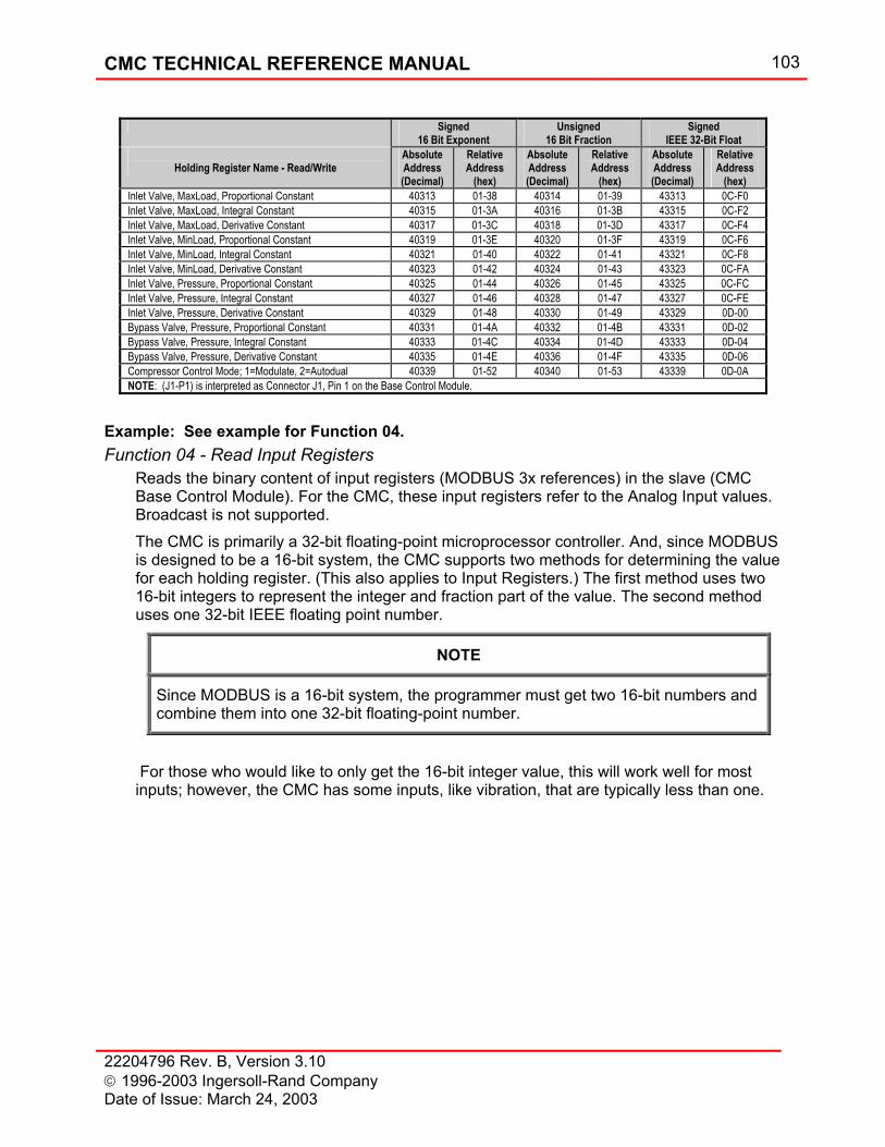
CMC TECHNICAL REFERENCE MANUAL 103
22204796 Rev. B, Version 3.10 1996-2003 Ingersoll-Rand Company Date of Issue: March 24, 2003
Signed
16 Bit Exponent Unsigned
16 Bit Fraction Signed
IEEE 32-Bit Float
Holding Register Name - Read/Write Absolute Address (Decimal)
Relative Address
(hex)
Absolute Address (Decimal)
Relative Address
(hex)
Absolute Address (Decimal)
Relative Address
(hex) Inlet Valve, MaxLoad, Proportional Constant 40313 01-38 40314 01-39 43313 0C-F0 Inlet Valve, MaxLoad, Integral Constant 40315 01-3A 40316 01-3B 43315 0C-F2 Inlet Valve, MaxLoad, Derivative Constant 40317 01-3C 40318 01-3D 43317 0C-F4 Inlet Valve, MinLoad, Proportional Constant 40319 01-3E 40320 01-3F 43319 0C-F6 Inlet Valve, MinLoad, Integral Constant 40321 01-40 40322 01-41 43321 0C-F8 Inlet Valve, MinLoad, Derivative Constant 40323 01-42 40324 01-43 43323 0C-FA Inlet Valve, Pressure, Proportional Constant 40325 01-44 40326 01-45 43325 0C-FC Inlet Valve, Pressure, Integral Constant 40327 01-46 40328 01-47 43327 0C-FE Inlet Valve, Pressure, Derivative Constant 40329 01-48 40330 01-49 43329 0D-00 Bypass Valve, Pressure, Proportional Constant 40331 01-4A 40332 01-4B 43331 0D-02 Bypass Valve, Pressure, Integral Constant 40333 01-4C 40334 01-4D 43333 0D-04 Bypass Valve, Pressure, Derivative Constant 40335 01-4E 40336 01-4F 43335 0D-06 Compressor Control Mode; 1=Modulate, 2=Autodual 40339 01-52 40340 01-53 43339 0D-0A NOTE: (J1-P1) is interpreted as Connector J1, Pin 1 on the Base Control Module.
Example: See example for Function 04. Function 04 - Read Input Registers
Reads the binary content of input registers (MODBUS 3x references) in the slave (CMC Base Control Module). For the CMC, these input registers refer to the Analog Input values. Broadcast is not supported. The CMC is primarily a 32-bit floating-point microprocessor controller. And, since MODBUS is designed to be a 16-bit system, the CMC supports two methods for determining the value for each holding register. (This also applies to Input Registers.) The first method uses two 16-bit integers to represent the integer and fraction part of the value. The second method uses one 32-bit IEEE floating point number.
NOTE
Since MODBUS is a 16-bit system, the programmer must get two 16-bit numbers and combine them into one 32-bit floating-point number.
For those who would like to only get the 16-bit integer value, this will work well for most inputs; however, the CMC has some inputs, like vibration, that are typically less than one.
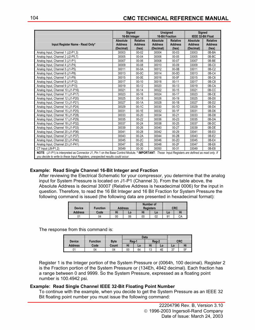
104 CMC TECHNICAL REFERENCE MANUAL
22204796 Rev. B, Version 3.10 1996-2003 Ingersoll-Rand Company
Date of Issue: March 24, 2003
Example: Read Single Channel 16-Bit Integer and Fraction After reviewing the Electrical Schematic for your compressor, you determine that the analog input for System Pressure is located on J1-P1 (Channel 3). From the table above, the Absolute Address is decimal 30007 (Relative Address is hexadecimal 0006) for the input in question. Therefore, to read the 16 Bit Integer and 16 Bit Fraction for System Pressure the following command is issued (the following data are presented in hexadecimal format):
The response from this command is:
Register 1 is the Integer portion of the System Pressure or (0064h, 100 decimal). Register 2 is the Fraction portion of the System Pressure or (134Eh, 4942 decimal). Each fraction has a range between 0 and 9999. So the System Pressure, expressed as a floating point number is 100.4942 psi.
Example: Read Single Channel IEEE 32-Bit Floating Point Number To continue with the example, when you decide to get the System Pressure as an IEEE 32 Bit floating point number you must issue the following command:
Signed 16-Bit Integer
Unsigned 16-Bit Fraction
Signed IEEE 32-Bit Float
Input Register Name - Read Only*
Absolute Address (Decimal)
Relative Address
(hex)
Absolute Address (Decimal)
Relative Address
(hex)
Absolute Address (Decimal)
Relative Address
(hex) Analog Input, Channel 1 (J2-P1,3) 30003 00-02 30004 00-03 33003 0B-BA Analog Input, Channel 2 (J2-P5,7) 30005 00-04 30006 00-05 33005 0B-BC Analog Input, Channel 3 (J1-P1) 30007 00-06 30008 00-07 33007 0B-BE Analog Input, Channel 4 (J1-P4) 30009 00-08 30010 00-09 33009 0B-C0 Analog Input, Channel 5 (J1-P5) 30011 00-0A 30012 00-0B 33011 0B-C2 Analog Input, Channel 6 (J1-P8) 30013 00-0C 30014 00-0D 33013 0B-C4 Analog Input, Channel 7 (J1-P9) 30015 00-0E 30016 00-0F 33015 0B-C6 Analog Input, Channel 8 (J1-P12) 30017 00-10 30018 00-11 33017 0B-C8 Analog Input, Channel 9 (J1-P13) 30019 00-12 30020 00-13 33019 0B-CA Analog Input, Channel 10 (J1-P16) 30021 00-14 30022 00-15 33021 0B-CC Analog Input, Channel 11 (J1-P17) 30023 00-16 30024 00-17 33023 0B-CE Analog Input, Channel 12 (J1-P20) 30025 00-18 30026 00-19 33025 0B-D0 Analog Input, Channel 13 (J1-P21) 30027 00-1A 30028 00-1B 33027 0B-D2 Analog Input, Channel 14 (J1-P24) 30029 00-1C 30030 00-1D 33029 0B-D4 Analog Input, Channel 15 (J1-P25) 30031 00-1E 30032 00-1F 33031 0B-D6 Analog Input, Channel 16 (J1-P28) 30033 00-20 30034 00-21 33033 0B-D8 Analog Input, Channel 17 (J1-P29) 30035 00-22 30036 00-23 33035 0B-DA Analog Input, Channel 18 (J1-P32) 30037 00-24 30038 00-25 33037 0B-DC Analog Input, Channel 19 (J1-P33) 30039 00-26 30040 00-27 33039 0B-DE Analog Input, Channel 20 (J1-P36) 30041 00-28 30042 00-29 33041 0B-E0 Analog Input, Channel 21 (J1-P37) 30043 00-2A 30044 00-2B 33043 0B-E2 Analog Input, Channel 22 (J1-P40) 30045 00-2C 30046 00-2D 33045 0B-E4 Analog Input, Channel 23 (J1-P41) 30047 00-2E 30048 00-2F 33047 0B-E6 CT Input (J9-P1,2) 30049 00-30 30050 00-31 33049 0B-E8 NOTE: (J1-P1) is interpreted as Connector J1, Pin 1 on the Base Control Module. * IMPORTANT: These Input Registers are defined as read only. If you decide to write to these Input Registers, unexpected results could occur.
Number of Device Function Address Registers CRC
Address Code Hi Lo Hi Lo Lo Hi 01 04 00 06 00 02 91 CA
Data Device Function Byte Reg-1 Reg-2 CRC
Address Code Count Hi Lo Hi Lo Lo Hi 01 04 04 00 64 13 4E 37 5F
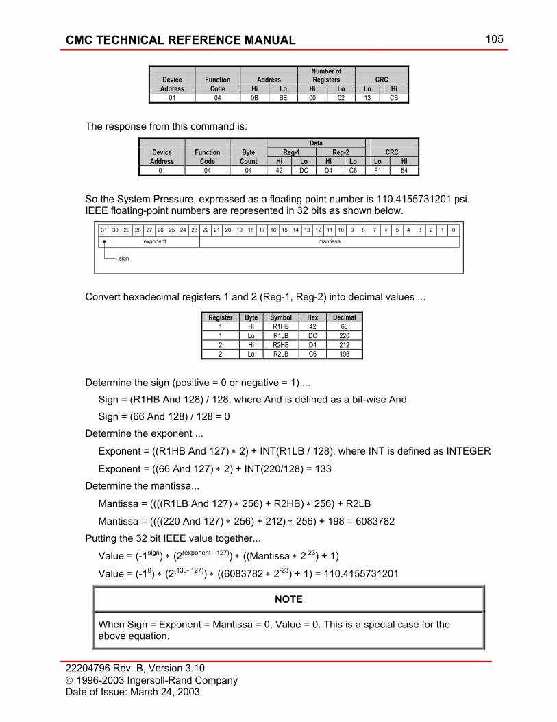
CMC TECHNICAL REFERENCE MANUAL 105
22204796 Rev. B, Version 3.10 1996-2003 Ingersoll-Rand Company Date of Issue: March 24, 2003
The response from this command is:
So the System Pressure, expressed as a floating point number is 110.4155731201 psi. IEEE floating-point numbers are represented in 32 bits as shown below.
Convert hexadecimal registers 1 and 2 (Reg-1, Reg-2) into decimal values ...
Determine the sign (positive = 0 or negative = 1) ...
Sign = (R1HB And 128) / 128, where And is defined as a bit-wise And Sign = (66 And 128) / 128 = 0
Determine the exponent ...
Exponent = ((R1HB And 127) ∗ 2) + INT(R1LB / 128), where INT is defined as INTEGER
Exponent = ((66 And 127) ∗ 2) + INT(220/128) = 133 Determine the mantissa...
Mantissa = ((((R1LB And 127) ∗ 256) + R2HB) ∗ 256) + R2LB
Mantissa = ((((220 And 127) ∗ 256) + 212) ∗ 256) + 198 = 6083782 Putting the 32 bit IEEE value together...
Value = (-1sign) ∗ (2(exponent - 127)) ∗ ((Mantissa ∗ 2-23) + 1)
Value = (-10) ∗ (2(133- 127)) ∗ ((6083782 ∗ 2-23) + 1) = 110.4155731201
NOTE
When Sign = Exponent = Mantissa = 0, Value = 0. This is a special case for the above equation.
Number of Device Function Address Registers CRC
Address Code Hi Lo Hi Lo Lo Hi 01 04 0B BE 00 02 13 CB
Data Device Function Byte Reg-1 Reg-2 CRC
Address Code Count Hi Lo Hi Lo Lo Hi 01 04 04 42 DC D4 C6 F1 54
31 30 29 28 27 26 25 24 23 22 21 20 19 18 17 16 15 14 13 12 11 10 9 8 7 6 5 4 3 2 1 0
exponent mantissa
sign
Register Byte Symbol Hex Decimal 1 Hi R1HB 42 66 1 Lo R1LB DC 220 2 Hi R2HB D4 212 2 Lo R2LB C6 198
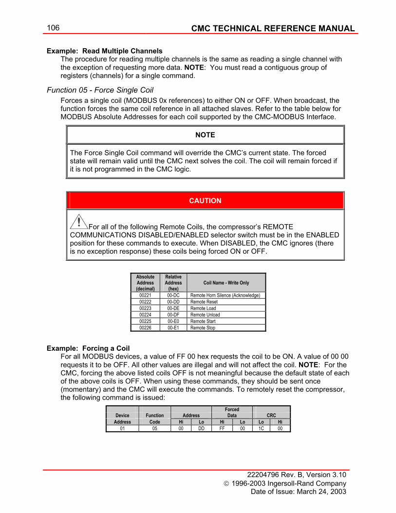
106 CMC TECHNICAL REFERENCE MANUAL
22204796 Rev. B, Version 3.10 1996-2003 Ingersoll-Rand Company
Date of Issue: March 24, 2003
Example: Read Multiple Channels The procedure for reading multiple channels is the same as reading a single channel with the exception of requesting more data. NOTE: You must read a contiguous group of registers (channels) for a single command.
Function 05 - Force Single Coil Forces a single coil (MODBUS 0x references) to either ON or OFF. When broadcast, the function forces the same coil reference in all attached slaves. Refer to the table below for MODBUS Absolute Addresses for each coil supported by the CMC-MODBUS Interface.
NOTE
The Force Single Coil command will override the CMC’s current state. The forced state will remain valid until the CMC next solves the coil. The coil will remain forced if it is not programmed in the CMC logic.
CAUTION
For all of the following Remote Coils, the compressor’s REMOTE COMMUNICATIONS DISABLED/ENABLED selector switch must be in the ENABLED position for these commands to execute. When DISABLED, the CMC ignores (there is no exception response) these coils being forced ON or OFF.
Example: Forcing a Coil For all MODBUS devices, a value of FF 00 hex requests the coil to be ON. A value of 00 00 requests it to be OFF. All other values are illegal and will not affect the coil. NOTE: For the CMC, forcing the above listed coils OFF is not meaningful because the default state of each of the above coils is OFF. When using these commands, they should be sent once (momentary) and the CMC will execute the commands. To remotely reset the compressor, the following command is issued:
Absolute Address (decimal)
Relative Address
(hex)
Coil Name - Write Only
00221 00-DC Remote Horn Silence (Acknowledge) 00222 00-DD Remote Reset 00223 00-DE Remote Load 00224 00-DF Remote Unload 00225 00-E0 Remote Start 00226 00-E1 Remote Stop
Forced Device Function Address Data CRC
Address Code Hi Lo Hi Lo Lo Hi 01 05 00 DD FF 00 1C 00
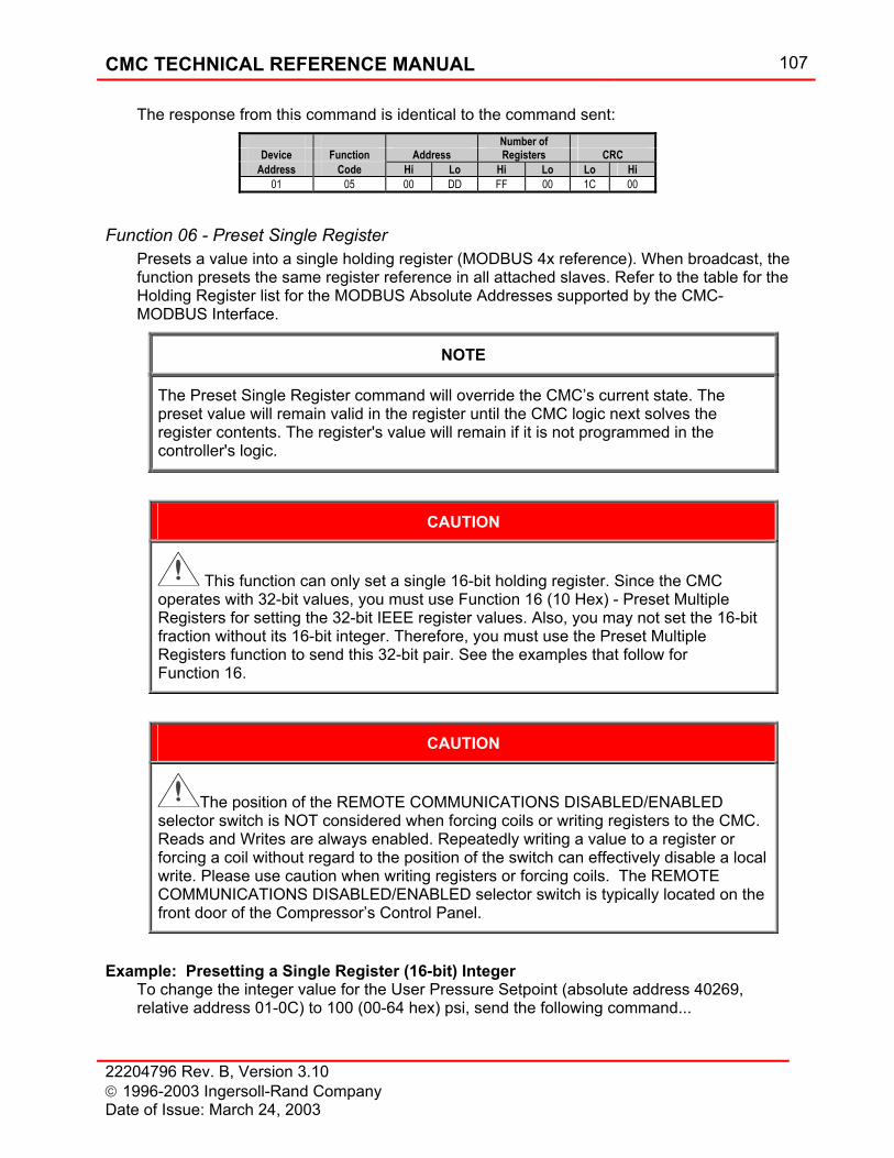
CMC TECHNICAL REFERENCE MANUAL 107
22204796 Rev. B, Version 3.10 1996-2003 Ingersoll-Rand Company Date of Issue: March 24, 2003
The response from this command is identical to the command sent:
Function 06 - Preset Single Register Presets a value into a single holding register (MODBUS 4x reference). When broadcast, the function presets the same register reference in all attached slaves. Refer to the table for the Holding Register list for the MODBUS Absolute Addresses supported by the CMC-MODBUS Interface.
NOTE
The Preset Single Register command will override the CMC’s current state. The preset value will remain valid in the register until the CMC logic next solves the register contents. The register's value will remain if it is not programmed in the controller's logic.
CAUTION
This function can only set a single 16-bit holding register. Since the CMC operates with 32-bit values, you must use Function 16 (10 Hex) - Preset Multiple Registers for setting the 32-bit IEEE register values. Also, you may not set the 16-bit fraction without its 16-bit integer. Therefore, you must use the Preset Multiple Registers function to send this 32-bit pair. See the examples that follow for Function 16.
CAUTION
The position of the REMOTE COMMUNICATIONS DISABLED/ENABLED selector switch is NOT considered when forcing coils or writing registers to the CMC. Reads and Writes are always enabled. Repeatedly writing a value to a register or forcing a coil without regard to the position of the switch can effectively disable a local write. Please use caution when writing registers or forcing coils. The REMOTE COMMUNICATIONS DISABLED/ENABLED selector switch is typically located on the front door of the Compressor’s Control Panel.
Example: Presetting a Single Register (16-bit) Integer To change the integer value for the User Pressure Setpoint (absolute address 40269, relative address 01-0C) to 100 (00-64 hex) psi, send the following command...
Number of Device Function Address Registers CRC
Address Code Hi Lo Hi Lo Lo Hi 01 05 00 DD FF 00 1C 00
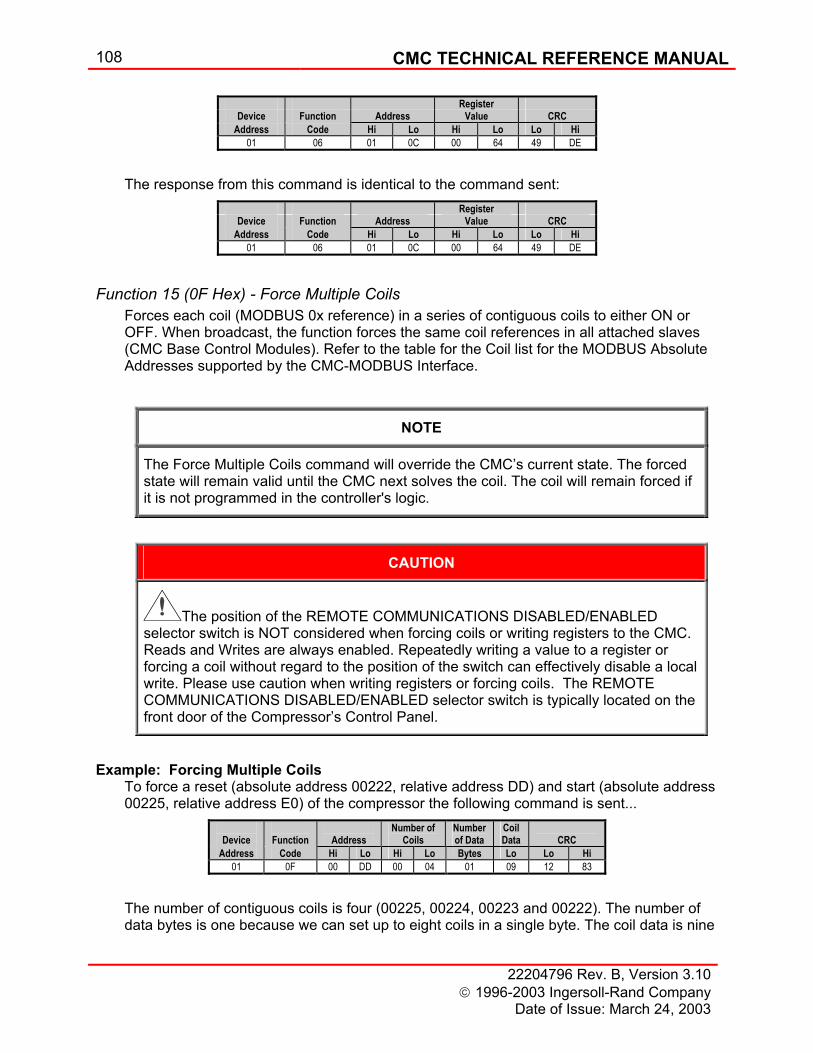
108 CMC TECHNICAL REFERENCE MANUAL
22204796 Rev. B, Version 3.10 1996-2003 Ingersoll-Rand Company
Date of Issue: March 24, 2003
The response from this command is identical to the command sent:
Function 15 (0F Hex) - Force Multiple Coils Forces each coil (MODBUS 0x reference) in a series of contiguous coils to either ON or OFF. When broadcast, the function forces the same coil references in all attached slaves (CMC Base Control Modules). Refer to the table for the Coil list for the MODBUS Absolute Addresses supported by the CMC-MODBUS Interface.
NOTE
The Force Multiple Coils command will override the CMC’s current state. The forced state will remain valid until the CMC next solves the coil. The coil will remain forced if it is not programmed in the controller's logic.
CAUTION
The position of the REMOTE COMMUNICATIONS DISABLED/ENABLED selector switch is NOT considered when forcing coils or writing registers to the CMC. Reads and Writes are always enabled. Repeatedly writing a value to a register or forcing a coil without regard to the position of the switch can effectively disable a local write. Please use caution when writing registers or forcing coils. The REMOTE COMMUNICATIONS DISABLED/ENABLED selector switch is typically located on the front door of the Compressor’s Control Panel.
Example: Forcing Multiple Coils To force a reset (absolute address 00222, relative address DD) and start (absolute address 00225, relative address E0) of the compressor the following command is sent...
The number of contiguous coils is four (00225, 00224, 00223 and 00222). The number of data bytes is one because we can set up to eight coils in a single byte. The coil data is nine
Register Device Function Address Value CRC
Address Code Hi Lo Hi Lo Lo Hi 01 06 01 0C 00 64 49 DE
Register Device Function Address Value CRC
Address Code Hi Lo Hi Lo Lo Hi 01 06 01 0C 00 64 49 DE
Device
Function
Address
Number of Coils
Number of Data
Coil Data
CRC
Address Code Hi Lo Hi Lo Bytes Lo Lo Hi 01 0F 00 DD 00 04 01 09 12 83
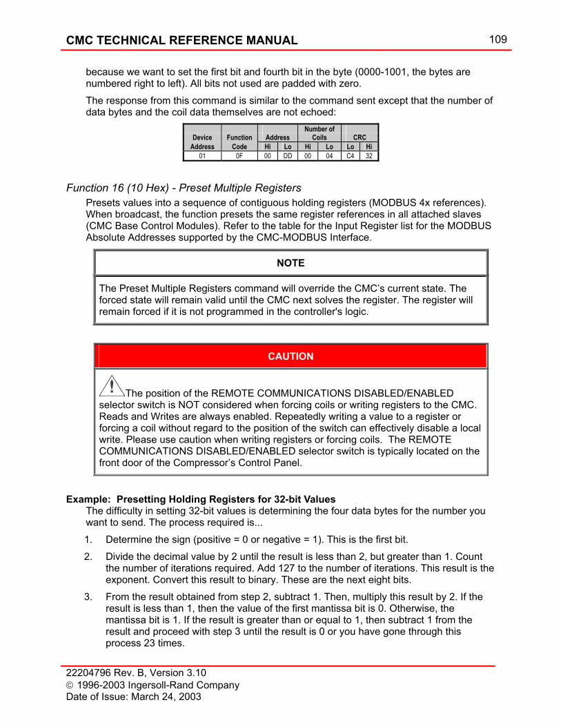
CMC TECHNICAL REFERENCE MANUAL 109
22204796 Rev. B, Version 3.10 1996-2003 Ingersoll-Rand Company Date of Issue: March 24, 2003
because we want to set the first bit and fourth bit in the byte (0000-1001, the bytes are numbered right to left). All bits not used are padded with zero. The response from this command is similar to the command sent except that the number of data bytes and the coil data themselves are not echoed:
Function 16 (10 Hex) - Preset Multiple Registers Presets values into a sequence of contiguous holding registers (MODBUS 4x references). When broadcast, the function presets the same register references in all attached slaves (CMC Base Control Modules). Refer to the table for the Input Register list for the MODBUS Absolute Addresses supported by the CMC-MODBUS Interface.
NOTE
The Preset Multiple Registers command will override the CMC’s current state. The forced state will remain valid until the CMC next solves the register. The register will remain forced if it is not programmed in the controller's logic.
CAUTION
The position of the REMOTE COMMUNICATIONS DISABLED/ENABLED selector switch is NOT considered when forcing coils or writing registers to the CMC. Reads and Writes are always enabled. Repeatedly writing a value to a register or forcing a coil without regard to the position of the switch can effectively disable a local write. Please use caution when writing registers or forcing coils. The REMOTE COMMUNICATIONS DISABLED/ENABLED selector switch is typically located on the front door of the Compressor’s Control Panel.
Example: Presetting Holding Registers for 32-bit Values The difficulty in setting 32-bit values is determining the four data bytes for the number you want to send. The process required is... 1. Determine the sign (positive = 0 or negative = 1). This is the first bit. 2. Divide the decimal value by 2 until the result is less than 2, but greater than 1. Count
the number of iterations required. Add 127 to the number of iterations. This result is the exponent. Convert this result to binary. These are the next eight bits.
3. From the result obtained from step 2, subtract 1. Then, multiply this result by 2. If the result is less than 1, then the value of the first mantissa bit is 0. Otherwise, the mantissa bit is 1. If the result is greater than or equal to 1, then subtract 1 from the result and proceed with step 3 until the result is 0 or you have gone through this process 23 times.
Number of Device Function Address Coils CRC
Address Code Hi Lo Hi Lo Lo Hi 01 0F 00 DD 00 04 C4 32
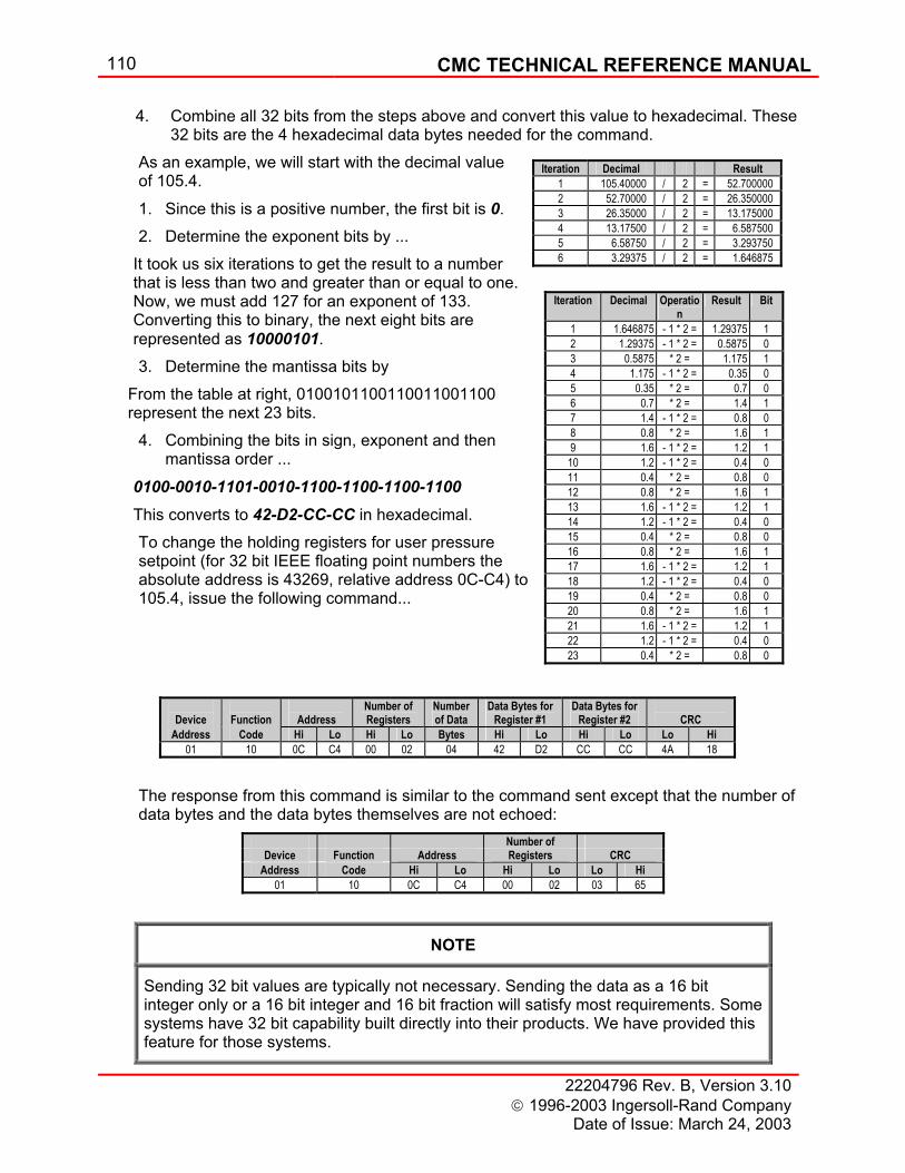
110 CMC TECHNICAL REFERENCE MANUAL
22204796 Rev. B, Version 3.10 1996-2003 Ingersoll-Rand Company
Date of Issue: March 24, 2003
4. Combine all 32 bits from the steps above and convert this value to hexadecimal. These 32 bits are the 4 hexadecimal data bytes needed for the command.
As an example, we will start with the decimal value of 105.4.
1. Since this is a positive number, the first bit is 0. 2. Determine the exponent bits by ...
It took us six iterations to get the result to a number that is less than two and greater than or equal to one. Now, we must add 127 for an exponent of 133. Converting this to binary, the next eight bits are represented as 10000101. 3. Determine the mantissa bits by
From the table at right, 0100101100110011001100 represent the next 23 bits.
4. Combining the bits in sign, exponent and then mantissa order ...
0100-0010-1101-0010-1100-1100-1100-1100
This converts to 42-D2-CC-CC in hexadecimal. To change the holding registers for user pressure setpoint (for 32 bit IEEE floating point numbers the absolute address is 43269, relative address 0C-C4) to 105.4, issue the following command...
The response from this command is similar to the command sent except that the number of data bytes and the data bytes themselves are not echoed:
NOTE
Sending 32 bit values are typically not necessary. Sending the data as a 16 bit integer only or a 16 bit integer and 16 bit fraction will satisfy most requirements. Some systems have 32 bit capability built directly into their products. We have provided this feature for those systems.
Iteration Decimal Result 1 105.40000 / 2 = 52.700000 2 52.70000 / 2 = 26.350000 3 26.35000 / 2 = 13.175000 4 13.17500 / 2 = 6.587500 5 6.58750 / 2 = 3.293750 6 3.29375 / 2 = 1.646875
Iteration Decimal Operation
Result Bit
1 1.646875 - 1 * 2 = 1.29375 1 2 1.29375 - 1 * 2 = 0.5875 0 3 0.5875 * 2 = 1.175 1 4 1.175 - 1 * 2 = 0.35 0 5 0.35 * 2 = 0.7 0 6 0.7 * 2 = 1.4 1 7 1.4 - 1 * 2 = 0.8 0 8 0.8 * 2 = 1.6 1 9 1.6 - 1 * 2 = 1.2 1
10 1.2 - 1 * 2 = 0.4 0 11 0.4 * 2 = 0.8 0 12 0.8 * 2 = 1.6 1 13 1.6 - 1 * 2 = 1.2 1 14 1.2 - 1 * 2 = 0.4 0 15 0.4 * 2 = 0.8 0 16 0.8 * 2 = 1.6 1 17 1.6 - 1 * 2 = 1.2 1 18 1.2 - 1 * 2 = 0.4 0 19 0.4 * 2 = 0.8 0 20 0.8 * 2 = 1.6 1 21 1.6 - 1 * 2 = 1.2 1 22 1.2 - 1 * 2 = 0.4 0 23 0.4 * 2 = 0.8 0
Device
Function
Address
Number of Registers
Number of Data
Data Bytes for Register #1
Data Bytes for Register #2
CRC
Address Code Hi Lo Hi Lo Bytes Hi Lo Hi Lo Lo Hi 01 10 0C C4 00 02 04 42 D2 CC CC 4A 18
Number of Device Function Address Registers CRC
Address Code Hi Lo Hi Lo Lo Hi 01 10 0C C4 00 02 03 65
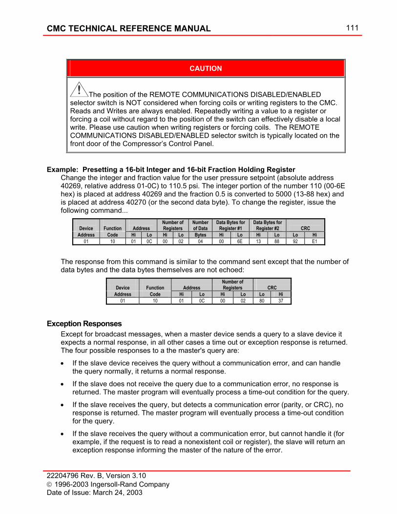
CMC TECHNICAL REFERENCE MANUAL 111
22204796 Rev. B, Version 3.10 1996-2003 Ingersoll-Rand Company Date of Issue: March 24, 2003
CAUTION
The position of the REMOTE COMMUNICATIONS DISABLED/ENABLED selector switch is NOT considered when forcing coils or writing registers to the CMC. Reads and Writes are always enabled. Repeatedly writing a value to a register or forcing a coil without regard to the position of the switch can effectively disable a local write. Please use caution when writing registers or forcing coils. The REMOTE COMMUNICATIONS DISABLED/ENABLED selector switch is typically located on the front door of the Compressor’s Control Panel.
Example: Presetting a 16-bit Integer and 16-bit Fraction Holding Register Change the integer and fraction value for the user pressure setpoint (absolute address 40269, relative address 01-0C) to 110.5 psi. The integer portion of the number 110 (00-6E hex) is placed at address 40269 and the fraction 0.5 is converted to 5000 (13-88 hex) and is placed at address 40270 (or the second data byte). To change the register, issue the following command...
The response from this command is similar to the command sent except that the number of data bytes and the data bytes themselves are not echoed:
Exception Responses Except for broadcast messages, when a master device sends a query to a slave device it expects a normal response, in all other cases a time out or exception response is returned. The four possible responses to a the master's query are:
• If the slave device receives the query without a communication error, and can handle the query normally, it returns a normal response.
• If the slave does not receive the query due to a communication error, no response is returned. The master program will eventually process a time-out condition for the query.
• If the slave receives the query, but detects a communication error (parity, or CRC), no response is returned. The master program will eventually process a time-out condition for the query.
• If the slave receives the query without a communication error, but cannot handle it (for example, if the request is to read a nonexistent coil or register), the slave will return an exception response informing the master of the nature of the error.
Device
Function
Address
Number of Registers
Number of Data
Data Bytes for Register #1
Data Bytes for Register #2
CRC
Address Code Hi Lo Hi Lo Bytes Hi Lo Hi Lo Lo Hi 01 10 01 0C 00 02 04 00 6E 13 88 92 E1
Number of Device Function Address Registers CRC
Address Code Hi Lo Hi Lo Lo Hi 01 10 01 0C 00 02 80 37
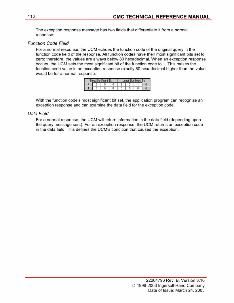
112 CMC TECHNICAL REFERENCE MANUAL
22204796 Rev. B, Version 3.10 1996-2003 Ingersoll-Rand Company
Date of Issue: March 24, 2003
The exception response message has two fields that differentiate it from a normal response:
Function Code Field For a normal response, the UCM echoes the function code of the original query in the function code field of the response. All function codes have their most significant bits set to zero; therefore, the values are always below 80 hexadecimal. When an exception response occurs, the UCM sets the most significant bit of the function code to 1. This makes the function code value in an exception response exactly 80 hexadecimal higher than the value would be for a normal response.
With the function code's most significant bit set, the application program can recognize an exception response and can examine the data field for the exception code.
Data Field For a normal response, the UCM will return information in the data field (depending upon the query message sent). For an exception response, the UCM returns an exception code in the data field. This defines the UCM’s condition that caused the exception.
Most Significant Bit Least Significant Bit 7 6 5 4 3 2 1 0 1 0 0 0 0 0 0 0
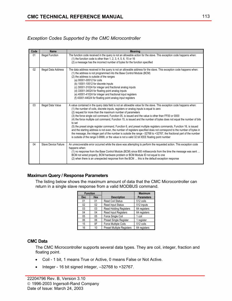
CMC TECHNICAL REFERENCE MANUAL 113
22204796 Rev. B, Version 3.10 1996-2003 Ingersoll-Rand Company Date of Issue: March 24, 2003
Exception Codes Supported by the CMC Microcontroller
Maximum Query / Response Parameters The listing below shows the maximum amount of data that the CMC Microcontroller can return in a single slave response from a valid MODBUS command.
CMC Data The CMC Microcontroller supports several data types. They are coil, integer, fraction and floating point.
• Coil - 1 bit, 1 means True or Active, 0 means False or Not Active.
• Integer - 16 bit signed integer, –32768 to +32767.
Code Name Meaning 01 Illegal Function The function code received in the query is not an allowable action for the slave. This exception code happens when:
(1) the function code is other than 1, 2, 3, 4, 5, 6, 15 or 16 (2) a message has the incorrect number of bytes for the function specified
02 Illegal Data Address The data address received in the query is not an allowable address for the slave. This exception code happens when: (1) the address is not programmed into the Base Control Module (BCM) (2) the address is outside of the ranges (a) 00001-00512 for coils (b) 10001-10512 for discrete inputs (c) 30001-31024 for integer and fractional analog inputs (d) 33001-34024 for floating point analog inputs (e) 40001-41024 for integer and fractional input registers (f) 43001-44024 for floating point analog input registers
03 Illegal Data Value A value contained in the query data field is not an allowable value for the slave. This exception code happens when: (1) the number of coils, discrete inputs, registers or analog inputs is equal to zero (2) request for more than the maximum number of parameters (3) the force single coil command, Function 05, is issued and the value is other than FF00 or 0000 (4) the force multiple coil command, Function 15, is issued and the number of bytes does not equal the number of bits to set (5) the preset single register command, Function 6, and preset multiple registers commands, Function 16, is issued and the starting address is not even, the number of registers specified does not correspond to the number of bytes in the message, the integer part of the number is outside the range –32768 to +32767, the fractional part of the number is outside of the range 0-9999, or the value is not a valid 32 bit IEEE floating point number
04 Slave Device Failure An unrecoverable error occurred while the slave was attempting to perform the requested action. This exception code
happens when: (1) no response from the Base Control Module (BCM) since 800 milliseconds from the time the message was sent … BCM not wired properly, BCM hardware problem or BCM Module ID not equal to one (2) when there is an unexpected response from the BCM … this is the default exception response
Function Maximum Dec Hex Description Parameters 01 01 Read Coil Status 512 coils 02 02 Read Input Status 512 inputs 03 03 Read Holding Registers 64 registers 04 04 Read Input Registers 64 registers 05 05 Force Single Coil 1 coil 06 06 Preset Single Register 1 register 15 0F Force Multiple Coils 512 coils 16 10 Preset Multiple Registers 64 registers
114 CMC TECHNICAL REFERENCE MANUAL
22204796 Rev. B, Version 3.10 1996-2003 Ingersoll-Rand Company
Date of Issue: March 24, 2003
• Fraction - 16 bit unsigned integer, 0 – 9999, represents the decimal (fractional) part of the number (1 represents 0.0001, 10 represents 0.0010, 100 represents 0.0100 and 1000 represents 0.1000).
• Floating Point - 32 bit IEEE number (requires reading two registers to get full number). For example if the System Pressure input is located on Channel 3 (address 30007) and the value of the pressure is 100.5 then: Address 30007 contains 100 Address 30008 contains 5000 Address 33007 contains the high 16 bits of the IEEE value for 100.5 Address 33008 contains the low 16 bits of IEEE value for 100.5 Additionally, the type of data in a location determines the commands that can be used to access the data. For the previous example of System Pressure addresses 00007, 03007, 10007, 13007, 40007 and 43023 return errors because coil, input status and holding register commands cannot read input register data.
Scaling and Units of Measure The MODBUS data are scaled in English engineering units. All pressures are in psi, temperatures in degrees F, vibrations in mils, and current in amps. For example, when the CMC Operator User Interface displays the system pressure as 7.73 kg/cm2, the value for system pressure obtained through MODBUS communications is 110 psi.
Communication Parameters Configuration of the communication speed (baud rate), parity, number of data bits and number of stop bits is available through the Ingersoll-Rand Service Tool and will be provided by a certified Ingersoll-Rand Service Representative.
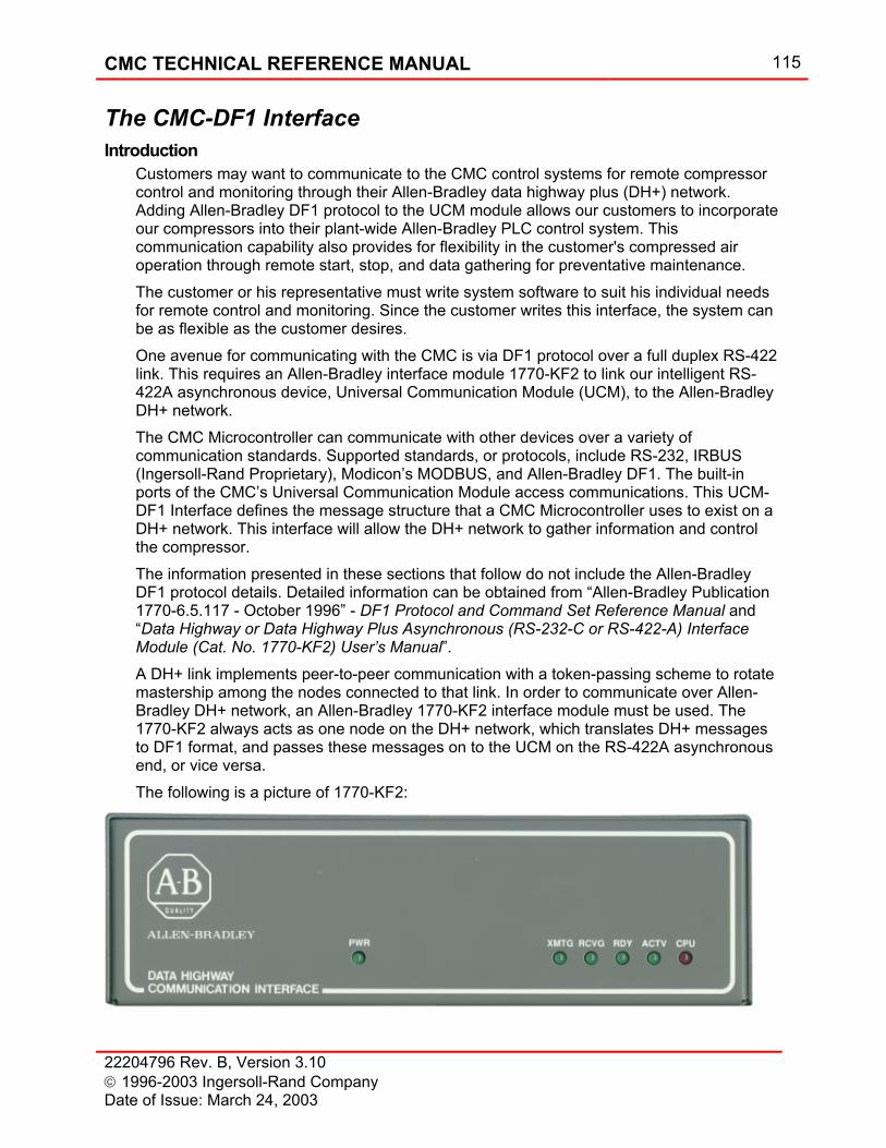
CMC TECHNICAL REFERENCE MANUAL 115
22204796 Rev. B, Version 3.10 1996-2003 Ingersoll-Rand Company Date of Issue: March 24, 2003
The CMC-DF1 Interface Introduction
Customers may want to communicate to the CMC control systems for remote compressor control and monitoring through their Allen-Bradley data highway plus (DH+) network. Adding Allen-Bradley DF1 protocol to the UCM module allows our customers to incorporate our compressors into their plant-wide Allen-Bradley PLC control system. This communication capability also provides for flexibility in the customer's compressed air operation through remote start, stop, and data gathering for preventative maintenance. The customer or his representative must write system software to suit his individual needs for remote control and monitoring. Since the customer writes this interface, the system can be as flexible as the customer desires. One avenue for communicating with the CMC is via DF1 protocol over a full duplex RS-422 link. This requires an Allen-Bradley interface module 1770-KF2 to link our intelligent RS-422A asynchronous device, Universal Communication Module (UCM), to the Allen-Bradley DH+ network. The CMC Microcontroller can communicate with other devices over a variety of communication standards. Supported standards, or protocols, include RS-232, IRBUS (Ingersoll-Rand Proprietary), Modicon’s MODBUS, and Allen-Bradley DF1. The built-in ports of the CMC’s Universal Communication Module access communications. This UCM-DF1 Interface defines the message structure that a CMC Microcontroller uses to exist on a DH+ network. This interface will allow the DH+ network to gather information and control the compressor. The information presented in these sections that follow do not include the Allen-Bradley DF1 protocol details. Detailed information can be obtained from “Allen-Bradley Publication 1770-6.5.117 - October 1996” - DF1 Protocol and Command Set Reference Manual and “Data Highway or Data Highway Plus Asynchronous (RS-232-C or RS-422-A) Interface Module (Cat. No. 1770-KF2) User’s Manual”. A DH+ link implements peer-to-peer communication with a token-passing scheme to rotate mastership among the nodes connected to that link. In order to communicate over Allen-Bradley DH+ network, an Allen-Bradley 1770-KF2 interface module must be used. The 1770-KF2 always acts as one node on the DH+ network, which translates DH+ messages to DF1 format, and passes these messages on to the UCM on the RS-422A asynchronous end, or vice versa. The following is a picture of 1770-KF2:
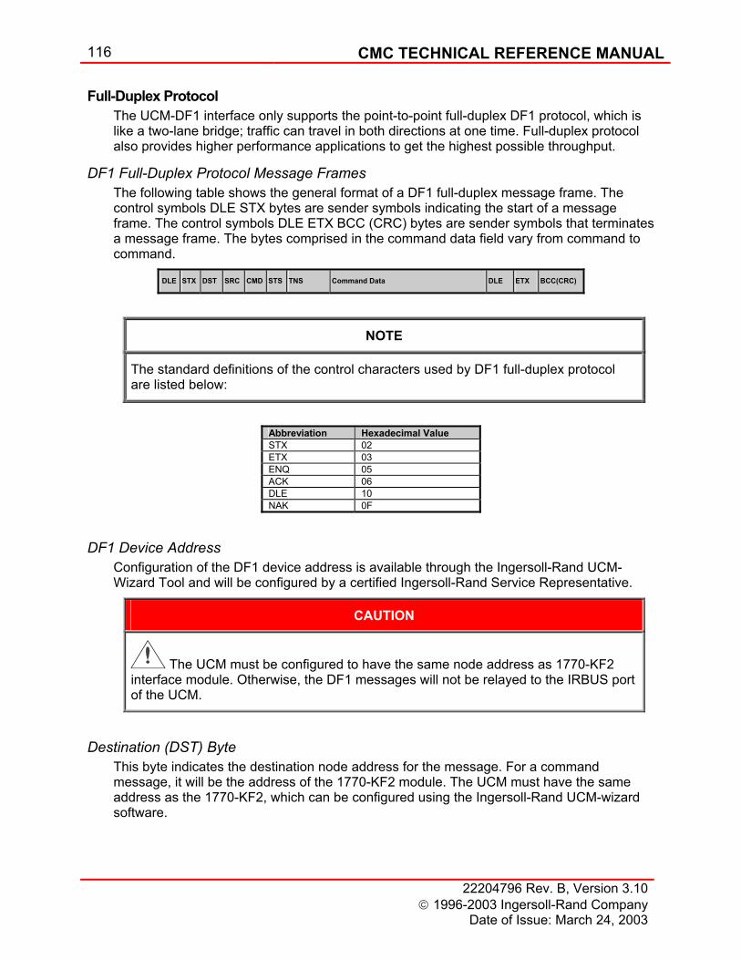
116 CMC TECHNICAL REFERENCE MANUAL
22204796 Rev. B, Version 3.10 1996-2003 Ingersoll-Rand Company
Date of Issue: March 24, 2003
Full-Duplex Protocol The UCM-DF1 interface only supports the point-to-point full-duplex DF1 protocol, which is like a two-lane bridge; traffic can travel in both directions at one time. Full-duplex protocol also provides higher performance applications to get the highest possible throughput.
DF1 Full-Duplex Protocol Message Frames The following table shows the general format of a DF1 full-duplex message frame. The control symbols DLE STX bytes are sender symbols indicating the start of a message frame. The control symbols DLE ETX BCC (CRC) bytes are sender symbols that terminates a message frame. The bytes comprised in the command data field vary from command to command.
NOTE
The standard definitions of the control characters used by DF1 full-duplex protocol are listed below:
Abbreviation Hexadecimal Value STX 02 ETX 03 ENQ 05 ACK 06 DLE 10 NAK 0F
DF1 Device Address Configuration of the DF1 device address is available through the Ingersoll-Rand UCM-Wizard Tool and will be configured by a certified Ingersoll-Rand Service Representative.
CAUTION
The UCM must be configured to have the same node address as 1770-KF2 interface module. Otherwise, the DF1 messages will not be relayed to the IRBUS port of the UCM.
Destination (DST) Byte This byte indicates the destination node address for the message. For a command message, it will be the address of the 1770-KF2 module. The UCM must have the same address as the 1770-KF2, which can be configured using the Ingersoll-Rand UCM-wizard software.
DLE STX DST SRC CMD STS TNS Command Data DLE ETX BCC(CRC)
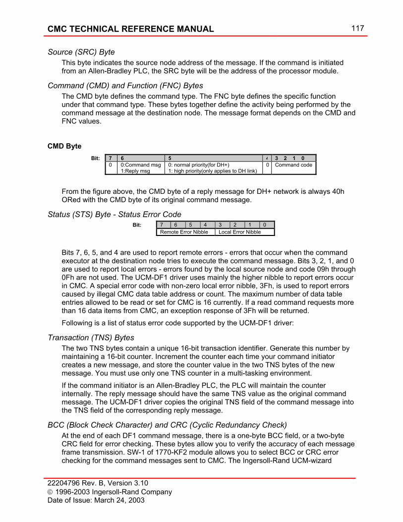
CMC TECHNICAL REFERENCE MANUAL 117
22204796 Rev. B, Version 3.10 1996-2003 Ingersoll-Rand Company Date of Issue: March 24, 2003
Source (SRC) Byte This byte indicates the source node address of the message. If the command is initiated from an Allen-Bradley PLC, the SRC byte will be the address of the processor module.
Command (CMD) and Function (FNC) Bytes The CMD byte defines the command type. The FNC byte defines the specific function under that command type. These bytes together define the activity being performed by the command message at the destination node. The message format depends on the CMD and FNC values.
CMD Byte
Bit: 7 6 5 4 3 2 1 0 0 0:Command msg
1:Reply msg 0: normal priority(for DH+) 1: high priority(only applies to DH link)
0 Command code
From the figure above, the CMD byte of a reply message for DH+ network is always 40h ORed with the CMD byte of its original command message.
Status (STS) Byte - Status Error Code Bit: 7 6 5 4 3 2 1 0 Remote Error Nibble Local Error Nibble
Bits 7, 6, 5, and 4 are used to report remote errors - errors that occur when the command executor at the destination node tries to execute the command message. Bits 3, 2, 1, and 0 are used to report local errors - errors found by the local source node and code 09h through 0Fh are not used. The UCM-DF1 driver uses mainly the higher nibble to report errors occur in CMC. A special error code with non-zero local error nibble, 3Fh, is used to report errors caused by illegal CMC data table address or count. The maximum number of data table entries allowed to be read or set for CMC is 16 currently. If a read command requests more than 16 data items from CMC, an exception response of 3Fh will be returned. Following is a list of status error code supported by the UCM-DF1 driver:
Transaction (TNS) Bytes The two TNS bytes contain a unique 16-bit transaction identifier. Generate this number by maintaining a 16-bit counter. Increment the counter each time your command initiator creates a new message, and store the counter value in the two TNS bytes of the new message. You must use only one TNS counter in a multi-tasking environment. If the command initiator is an Allen-Bradley PLC, the PLC will maintain the counter internally. The reply message should have the same TNS value as the original command message. The UCM-DF1 driver copies the original TNS field of the command message into the TNS field of the corresponding reply message.
BCC (Block Check Character) and CRC (Cyclic Redundancy Check) At the end of each DF1 command message, there is a one-byte BCC field, or a two-byte CRC field for error checking. These bytes allow you to verify the accuracy of each message frame transmission. SW-1 of 1770-KF2 module allows you to select BCC or CRC error checking for the command messages sent to CMC. The Ingersoll-Rand UCM-wizard
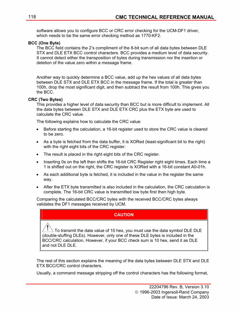
118 CMC TECHNICAL REFERENCE MANUAL
22204796 Rev. B, Version 3.10 1996-2003 Ingersoll-Rand Company
Date of Issue: March 24, 2003
software allows you to configure BCC or CRC error checking for the UCM-DF1 driver, which needs to be the same error checking method as 1770-KF2.
BCC (One Byte) The BCC field contains the 2’s compliment of the 8-bit sum of all data bytes between DLE STX and DLE ETX BCC control characters. BCC provides a medium level of data security. It cannot detect either the transposition of bytes during transmission nor the insertion or deletion of the value zero within a message frame.
Another way to quickly determine a BCC value, add up the hex values of all data bytes between DLE STX and DLE ETX BCC in the message frame. If the total is greater than 100h, drop the most significant digit, and then subtract the result from 100h. This gives you the BCC.
CRC (Two Bytes) This provides a higher level of data security than BCC but is more difficult to implement. All the data bytes between DLE STX and DLE ETX CRC plus the ETX byte are used to calculate the CRC value. The following explains how to calculate the CRC value:
• Before starting the calculation, a 16-bit register used to store the CRC value is cleared to be zero.
• As a byte is fetched from the data buffer, it is XORed (least-significant bit to the right) with the right eight bits of the CRC register.
• The result is placed in the right eight bits of the CRC register.
• Inserting 0s on the left then shifts the 16-bit CRC Register right eight times. Each time a 1 is shifted out on the right, the CRC register is XORed with a 16-bit constant A0-01h.
• As each additional byte is fetched, it is included in the value in the register the same way.
• After the ETX byte transmitted is also included in the calculation, the CRC calculation is complete. The 16-bit CRC value is transmitted low byte first then high byte.
Comparing the calculated BCC/CRC bytes with the received BCC/CRC bytes always validates the DF1 messages received by UCM.
CAUTION
To transmit the data value of 10 hex, you must use the data symbol DLE DLE (double-stuffing DLEs). However, only one of these DLE bytes is included in the BCC/CRC calculation. However, if your BCC check sum is 10 hex, send it as DLE and not DLE DLE.
The rest of this section explains the meaning of the data bytes between DLE STX and DLE ETX BCC/CRC control characters. Usually, a command message stripping off the control characters has the following format,

CMC TECHNICAL REFERENCE MANUAL 119
22204796 Rev. B, Version 3.10 1996-2003 Ingersoll-Rand Company Date of Issue: March 24, 2003
DST SRC CMD STS TNS command specific data packet
a reply message to a read command has the format below,
SRC DST CMD STS TNS command specific data packet
a reply message to a write command has the following format,
SRC DST CMD STS TNS
The DST and SRC bytes of a reply message are formed by interchanging the DST and SRC bytes of the corresponding command message. The combination of SRC, CMD, and TNS bytes uniquely identifies every message packet. If all fields are the same, the message is considered to be a duplicate. The UCM-DF1 driver does not detect duplicate messages.
Scaling and Units of Measure The MODBUS data are scaled in English engineering units. All pressures are in psi, temperatures in degrees F, vibrations in mils, and current in amps. For example, when the CMC Operator User Interface displays the system pressure as 7.73 kg/cm2, the value for system pressure obtained through MODBUS communications is 110 psi.
Data Addressing The CMC is primarily a 32-bit floating-point microprocessor controller. We support two methods for determining the analog data value. These methods are two 16-bit integers representing the integer and fraction part of the number and one 32-bit IEEE floating point number. (NOTE: If you use the 16-bit system, you must get two 16-bit numbers and combine them into one 32-bit floating point number.) The UCM-DF1 interface can prepare data as either two 16-bit integers or one 32-bit floating point number with respect to the received DF1 command. The Allen-Bradley PLC floating point format is a subset of IEEE STD 754-1985. Accessing data from the CMC via DF1 interface emulates accessing data from a PLC5 or SLC5/04. In SLC 5/04, each data file can hold up to 256 data elements (element number: 0-255) and the file number has to be in the same range (0-255). The UCM-DF1 addressing scheme uses this file/element structure and complies with the SLC5/04’s limits on file number and element number. Please see next section for details. A DF1 command initiator is a device on the DH+ network that initiates the query or set commands to the CMC. It can be an Allen-Bradley PLC or other device that can send/receive a PLC5 Typed Read (Write) or SLC Typed Logical Read (Write) command/response.
CMC as PLC5 As to treating CMC as a PLC5, the command initiator can issue a PLC5 Typed Read (Write) command to the CMC. Please see the section on Supported Functions for detailed message format. For a PLC5 Typed Write command, the data can be sent as either two 16-bit integers or one 32-bit floating point. If a PLC5 or SLC5/04 issues the command, the setpoint data type is determined by the local data file type used to store it.
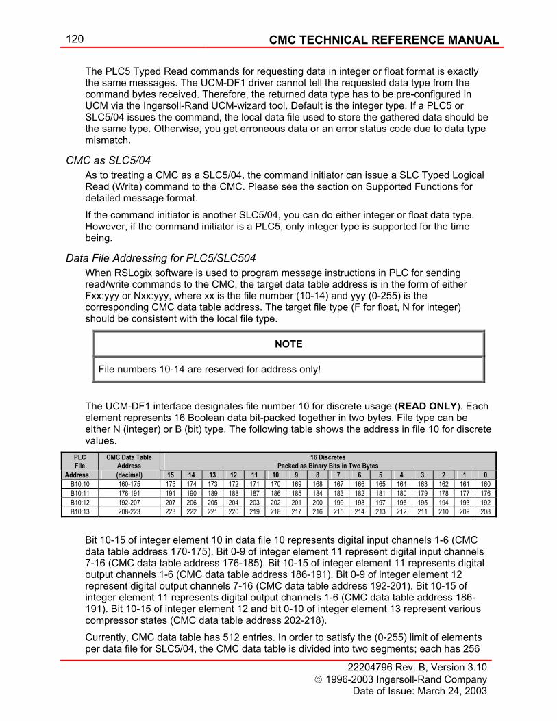
120 CMC TECHNICAL REFERENCE MANUAL
22204796 Rev. B, Version 3.10 1996-2003 Ingersoll-Rand Company
Date of Issue: March 24, 2003
The PLC5 Typed Read commands for requesting data in integer or float format is exactly the same messages. The UCM-DF1 driver cannot tell the requested data type from the command bytes received. Therefore, the returned data type has to be pre-configured in UCM via the Ingersoll-Rand UCM-wizard tool. Default is the integer type. If a PLC5 or SLC5/04 issues the command, the local data file used to store the gathered data should be the same type. Otherwise, you get erroneous data or an error status code due to data type mismatch.
CMC as SLC5/04 As to treating a CMC as a SLC5/04, the command initiator can issue a SLC Typed Logical Read (Write) command to the CMC. Please see the section on Supported Functions for detailed message format. If the command initiator is another SLC5/04, you can do either integer or float data type. However, if the command initiator is a PLC5, only integer type is supported for the time being.
Data File Addressing for PLC5/SLC504 When RSLogix software is used to program message instructions in PLC for sending read/write commands to the CMC, the target data table address is in the form of either Fxx:yyy or Nxx:yyy, where xx is the file number (10-14) and yyy (0-255) is the corresponding CMC data table address. The target file type (F for float, N for integer) should be consistent with the local file type.
NOTE
File numbers 10-14 are reserved for address only!
The UCM-DF1 interface designates file number 10 for discrete usage (READ ONLY). Each element represents 16 Boolean data bit-packed together in two bytes. File type can be either N (integer) or B (bit) type. The following table shows the address in file 10 for discrete values.
PLC File
CMC Data Table Address
16 Discretes Packed as Binary Bits in Two Bytes
Address (decimal) 15 14 13 12 11 10 9 8 7 6 5 4 3 2 1 0 B10:10 160-175 175 174 173 172 171 170 169 168 167 166 165 164 163 162 161 160 B10:11 176-191 191 190 189 188 187 186 185 184 183 182 181 180 179 178 177 176 B10:12 192-207 207 206 205 204 203 202 201 200 199 198 197 196 195 194 193 192 B10:13 208-223 223 222 221 220 219 218 217 216 215 214 213 212 211 210 209 208
Bit 10-15 of integer element 10 in data file 10 represents digital input channels 1-6 (CMC data table address 170-175). Bit 0-9 of integer element 11 represent digital input channels 7-16 (CMC data table address 176-185). Bit 10-15 of integer element 11 represents digital output channels 1-6 (CMC data table address 186-191). Bit 0-9 of integer element 12 represent digital output channels 7-16 (CMC data table address 192-201). Bit 10-15 of integer element 11 represents digital output channels 1-6 (CMC data table address 186-191). Bit 10-15 of integer element 12 and bit 0-10 of integer element 13 represent various compressor states (CMC data table address 202-218). Currently, CMC data table has 512 entries. In order to satisfy the (0-255) limit of elements per data file for SLC5/04, the CMC data table is divided into two segments; each has 256

CMC TECHNICAL REFERENCE MANUAL 121
22204796 Rev. B, Version 3.10 1996-2003 Ingersoll-Rand Company Date of Issue: March 24, 2003
entries. File number 11 is designated to the first 256 entries. File number 12 is for the second 256 entries. If the CMC data table gets expanded later, the subsequent file number will be used. According to the above, N11:170 refers to the 170-th item in the CMC data table, which is the digital input channel 1. Similarly, N12:170 will be the 426-th = (170+256) item in the CMC data table. If an invalid file or element number is used, you will get a 3Fh-status error code. See the status error code section for details. The number of bytes per element is 2 for integer type and 4 for float type. The assigned message length in elements for local data file should be a multiple of 2 for integer type. If it is an odd number, only the 2-byte integer (whole) part will be transmitted for the last data item. Since the CMC has programmable analog and discrete inputs and outputs, the programmer must use the electrical schematic supplied with the machine to determine which function name and units of measure are associated with each input and output.
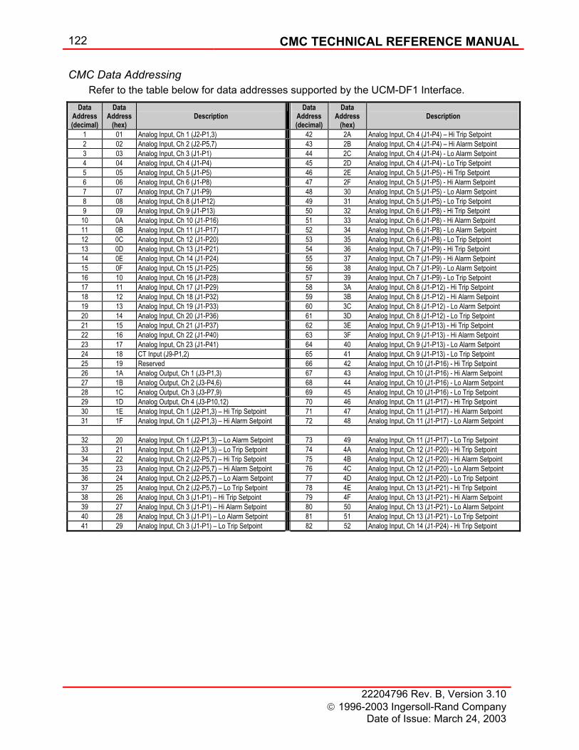
122 CMC TECHNICAL REFERENCE MANUAL
22204796 Rev. B, Version 3.10 1996-2003 Ingersoll-Rand Company
Date of Issue: March 24, 2003
CMC Data Addressing Refer to the table below for data addresses supported by the UCM-DF1 Interface.
Data Address (decimal)
Data Address
(hex)
Description
Data Address (decimal)
Data Address
(hex)
Description
1 01 Analog Input, Ch 1 (J2-P1,3) 42 2A Analog Input, Ch 4 (J1-P4) – Hi Trip Setpoint 2 02 Analog Input, Ch 2 (J2-P5,7) 43 2B Analog Input, Ch 4 (J1-P4) – Hi Alarm Setpoint 3 03 Analog Input, Ch 3 (J1-P1) 44 2C Analog Input, Ch 4 (J1-P4) - Lo Alarm Setpoint 4 04 Analog Input, Ch 4 (J1-P4) 45 2D Analog Input, Ch 4 (J1-P4) - Lo Trip Setpoint 5 05 Analog Input, Ch 5 (J1-P5) 46 2E Analog Input, Ch 5 (J1-P5) - Hi Trip Setpoint 6 06 Analog Input, Ch 6 (J1-P8) 47 2F Analog Input, Ch 5 (J1-P5) - Hi Alarm Setpoint 7 07 Analog Input, Ch 7 (J1-P9) 48 30 Analog Input, Ch 5 (J1-P5) - Lo Alarm Setpoint 8 08 Analog Input, Ch 8 (J1-P12) 49 31 Analog Input, Ch 5 (J1-P5) - Lo Trip Setpoint 9 09 Analog Input, Ch 9 (J1-P13) 50 32 Analog Input, Ch 6 (J1-P8) - Hi Trip Setpoint 10 0A Analog Input, Ch 10 (J1-P16) 51 33 Analog Input, Ch 6 (J1-P8) - Hi Alarm Setpoint 11 0B Analog Input, Ch 11 (J1-P17) 52 34 Analog Input, Ch 6 (J1-P8) - Lo Alarm Setpoint 12 0C Analog Input, Ch 12 (J1-P20) 53 35 Analog Input, Ch 6 (J1-P8) - Lo Trip Setpoint 13 0D Analog Input, Ch 13 (J1-P21) 54 36 Analog Input, Ch 7 (J1-P9) - Hi Trip Setpoint 14 0E Analog Input, Ch 14 (J1-P24) 55 37 Analog Input, Ch 7 (J1-P9) - Hi Alarm Setpoint 15 0F Analog Input, Ch 15 (J1-P25) 56 38 Analog Input, Ch 7 (J1-P9) - Lo Alarm Setpoint 16 10 Analog Input, Ch 16 (J1-P28) 57 39 Analog Input, Ch 7 (J1-P9) - Lo Trip Setpoint 17 11 Analog Input, Ch 17 (J1-P29) 58 3A Analog Input, Ch 8 (J1-P12) - Hi Trip Setpoint 18 12 Analog Input, Ch 18 (J1-P32) 59 3B Analog Input, Ch 8 (J1-P12) - Hi Alarm Setpoint 19 13 Analog Input, Ch 19 (J1-P33) 60 3C Analog Input, Ch 8 (J1-P12) - Lo Alarm Setpoint 20 14 Analog Input, Ch 20 (J1-P36) 61 3D Analog Input, Ch 8 (J1-P12) - Lo Trip Setpoint 21 15 Analog Input, Ch 21 (J1-P37) 62 3E Analog Input, Ch 9 (J1-P13) - Hi Trip Setpoint 22 16 Analog Input, Ch 22 (J1-P40) 63 3F Analog Input, Ch 9 (J1-P13) - Hi Alarm Setpoint 23 17 Analog Input, Ch 23 (J1-P41) 64 40 Analog Input, Ch 9 (J1-P13) - Lo Alarm Setpoint 24 18 CT Input (J9-P1,2) 65 41 Analog Input, Ch 9 (J1-P13) - Lo Trip Setpoint 25 19 Reserved 66 42 Analog Input, Ch 10 (J1-P16) - Hi Trip Setpoint 26 1A Analog Output, Ch 1 (J3-P1,3) 67 43 Analog Input, Ch 10 (J1-P16) - Hi Alarm Setpoint 27 1B Analog Output, Ch 2 (J3-P4,6) 68 44 Analog Input, Ch 10 (J1-P16) - Lo Alarm Setpoint 28 1C Analog Output, Ch 3 (J3-P7,9) 69 45 Analog Input, Ch 10 (J1-P16) - Lo Trip Setpoint 29 1D Analog Output, Ch 4 (J3-P10,12) 70 46 Analog Input, Ch 11 (J1-P17) - Hi Trip Setpoint 30 1E Analog Input, Ch 1 (J2-P1,3) – Hi Trip Setpoint 71 47 Analog Input, Ch 11 (J1-P17) - Hi Alarm Setpoint 31 1F Analog Input, Ch 1 (J2-P1,3) – Hi Alarm Setpoint 72 48 Analog Input, Ch 11 (J1-P17) - Lo Alarm Setpoint
32 20 Analog Input, Ch 1 (J2-P1,3) – Lo Alarm Setpoint 73 49 Analog Input, Ch 11 (J1-P17) - Lo Trip Setpoint 33 21 Analog Input, Ch 1 (J2-P1,3) – Lo Trip Setpoint 74 4A Analog Input, Ch 12 (J1-P20) - Hi Trip Setpoint 34 22 Analog Input, Ch 2 (J2-P5,7) – Hi Trip Setpoint 75 4B Analog Input, Ch 12 (J1-P20) - Hi Alarm Setpoint 35 23 Analog Input, Ch 2 (J2-P5,7) – Hi Alarm Setpoint 76 4C Analog Input, Ch 12 (J1-P20) - Lo Alarm Setpoint 36 24 Analog Input, Ch 2 (J2-P5,7) – Lo Alarm Setpoint 77 4D Analog Input, Ch 12 (J1-P20) - Lo Trip Setpoint 37 25 Analog Input, Ch 2 (J2-P5,7) – Lo Trip Setpoint 78 4E Analog Input, Ch 13 (J1-P21) - Hi Trip Setpoint 38 26 Analog Input, Ch 3 (J1-P1) – Hi Trip Setpoint 79 4F Analog Input, Ch 13 (J1-P21) - Hi Alarm Setpoint 39 27 Analog Input, Ch 3 (J1-P1) – Hi Alarm Setpoint 80 50 Analog Input, Ch 13 (J1-P21) - Lo Alarm Setpoint 40 28 Analog Input, Ch 3 (J1-P1) – Lo Alarm Setpoint 81 51 Analog Input, Ch 13 (J1-P21) - Lo Trip Setpoint 41 29 Analog Input, Ch 3 (J1-P1) – Lo Trip Setpoint 82 52 Analog Input, Ch 14 (J1-P24) - Hi Trip Setpoint
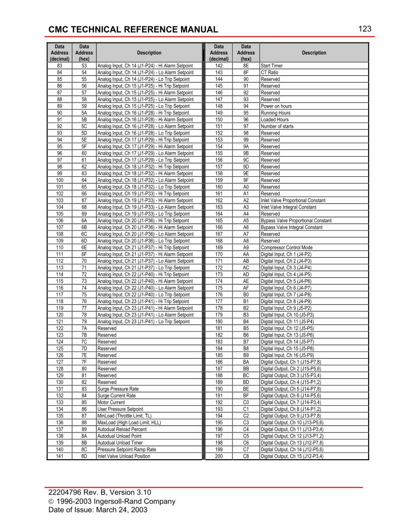
CMC TECHNICAL REFERENCE MANUAL 123
22204796 Rev. B, Version 3.10 1996-2003 Ingersoll-Rand Company Date of Issue: March 24, 2003
Data Address (decimal)
Data Address
(hex)
Description
Data Address (decimal)
Data Address
(hex)
Description
83 53 Analog Input, Ch 14 (J1-P24) - Hi Alarm Setpoint 142 8E Start Timer 84 54 Analog Input, Ch 14 (J1-P24) - Lo Alarm Setpoint 143 8F CT Ratio 85 55 Analog Input, Ch 14 (J1-P24) - Lo Trip Setpoint 144 90 Reserved 86 56 Analog Input, Ch 15 (J1-P25) - Hi Trip Setpoint 145 91 Reserved 87 57 Analog Input, Ch 15 (J1-P25) - Hi Alarm Setpoint 146 92 Reserved 88 58 Analog Input, Ch 15 (J1-P25) - Lo Alarm Setpoint 147 93 Reserved 89 59 Analog Input, Ch 15 (J1-P25) - Lo Trip Setpoint 148 94 Power on hours 90 5A Analog Input, Ch 16 (J1-P28) - Hi Trip Setpoint 149 95 Running Hours 91 5B Analog Input, Ch 16 (J1-P28) - Hi Alarm Setpoint 150 96 Loaded Hours 92 5C Analog Input, Ch 16 (J1-P28) - Lo Alarm Setpoint 151 97 Number of starts 93 5D Analog Input, Ch 16 (J1-P28) - Lo Trip Setpoint 152 98 Reserved 94 5E Analog Input, Ch 17 (J1-P29) - Hi Trip Setpoint 153 99 Reserved 95 5F Analog Input, Ch 17 (J1-P29) - Hi Alarm Setpoint 154 9A Reserved 96 60 Analog Input, Ch 17 (J1-P29) - Lo Alarm Setpoint 155 9B Reserved 97 61 Analog Input, Ch 17 (J1-P29) - Lo Trip Setpoint 156 9C Reserved 98 62 Analog Input, Ch 18 (J1-P32) - Hi Trip Setpoint 157 9D Reserved 99 63 Analog Input, Ch 18 (J1-P32) - Hi Alarm Setpoint 158 9E Reserved
100 64 Analog Input, Ch 18 (J1-P32) - Lo Alarm Setpoint 159 9F Reserved 101 65 Analog Input, Ch 18 (J1-P32) - Lo Trip Setpoint 160 A0 Reserved 102 66 Analog Input, Ch 19 (J1-P33) - Hi Trip Setpoint 161 A1 Reserved 103 67 Analog Input, Ch 19 (J1-P33) - Hi Alarm Setpoint 162 A2 Inlet Valve Proportional Constant 104 68 Analog Input, Ch 19 (J1-P33) - Lo Alarm Setpoint 163 A3 Inlet Valve Integral Constant 105 69 Analog Input, Ch 19 (J1-P33) - Lo Trip Setpoint 164 A4 Reserved 106 6A Analog Input, Ch 20 (J1-P36) - Hi Trip Setpoint 165 A5 Bypass Valve Proportional Constant 107 6B Analog Input, Ch 20 (J1-P36) - Hi Alarm Setpoint 166 A6 Bypass Valve Integral Constant 108 6C Analog Input, Ch 20 (J1-P36) - Lo Alarm Setpoint 167 A7 Reserved 109 6D Analog Input, Ch 20 (J1-P36) - Lo Trip Setpoint 168 A8 Reserved 110 6E Analog Input, Ch 21 (J1-P37) - Hi Trip Setpoint 169 A9 Compressor Control Mode 111 6F Analog Input, Ch 21 (J1-P37) - Hi Alarm Setpoint 170 AA Digital Input, Ch 1 (J4-P2) 112 70 Analog Input, Ch 21 (J1-P37) - Lo Alarm Setpoint 171 AB Digital Input, Ch 2 (J4-P3) 113 71 Analog Input, Ch 21 (J1-P37) - Lo Trip Setpoint 172 AC Digital Input, Ch 3 (J4-P4) 114 72 Analog Input, Ch 22 (J1-P40) - Hi Trip Setpoint 173 AD Digital Input, Ch 4 (J4-P5) 115 73 Analog Input, Ch 22 (J1-P40) - Hi Alarm Setpoint 174 AE Digital Input, Ch 5 (J4-P6) 116 74 Analog Input, Ch 22 (J1-P40) - Lo Alarm Setpoint 175 AF Digital Input, Ch 6 (J4-P7) 117 75 Analog Input, Ch 22 (J1-P40) - Lo Trip Setpoint 176 B0 Digital Input, Ch 7 (J4-P8) 118 76 Analog Input, Ch 23 (J1-P41) - Hi Trip Setpoint 177 B1 Digital Input, Ch 8 (J4-P9) 119 77 Analog Input, Ch 23 (J1-P41) - Hi Alarm Setpoint 178 B2 Digital Input, Ch 9 (J5-P2) 120 78 Analog Input, Ch 23 (J1-P41) - Lo Alarm Setpoint 179 B3 Digital Input, Ch 10 (J5-P3) 121 79 Analog Input, Ch 23 (J1-P41) - Lo Trip Setpoint 180 B4 Digital Input, Ch 11 (J5-P4) 122 7A Reserved 181 B5 Digital Input, Ch 12 (J5-P5) 123 7B Reserved 182 B6 Digital Input, Ch 13 (J5-P6) 124 7C Reserved 183 B7 Digital Input, Ch 14 (J5-P7) 125 7D Reserved 184 B8 Digital Input, Ch 15 (J5-P8) 126 7E Reserved 185 B9 Digital Input, Ch 16 (J5-P9) 127 7F Reserved 186 BA Digital Output, Ch 1 (J15-P7,8) 128 80 Reserved 187 BB Digital Output, Ch 2 (J15-P5,6) 129 81 Reserved 188 BC Digital Output, Ch 3 (J15-P3,4) 130 82 Reserved 189 BD Digital Output, Ch 4 (J15-P1,2) 131 83 Surge Pressure Rate 190 BE Digital Output, Ch 5 (J14-P7,8) 132 84 Surge Current Rate 191 BF Digital Output, Ch 6 (J14-P5,6) 133 85 Motor Current 192 C0 Digital Output, Ch 7 (J14-P3,4) 134 86 User Pressure Setpoint 193 C1 Digital Output, Ch 8 (J14-P1,2) 135 87 MinLoad (Throttle Limit, TL) 194 C2 Digital Output, Ch 9 (J13-P7,8) 136 88 MaxLoad (High Load Limit, HLL) 195 C3 Digital Output, Ch 10 (J13-P5,6) 137 89 Autodual Reload Percent 196 C4 Digital Output, Ch 11 (J13-P3,4) 138 8A Autodual Unload Point 197 C5 Digital Output, Ch 12 (J13-P1,2) 139 8B Autodual Unload Timer 198 C6 Digital Output, Ch 13 (J12-P7,8) 140 8C Pressure Setpoint Ramp Rate 199 C7 Digital Output, Ch 14 (J12-P5,6) 141 8D Inlet Valve Unload Position 200 C8 Digital Output, Ch 15 (J12-P3,4)
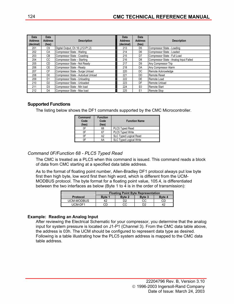
124 CMC TECHNICAL REFERENCE MANUAL
22204796 Rev. B, Version 3.10 1996-2003 Ingersoll-Rand Company
Date of Issue: March 24, 2003
Data
Address (decimal)
Data Address
(hex)
Description
Data Address (decimal)
Data Address
(hex)
Description
201 C9 Digital Output, Ch 16 (J12-P1,2) 213 D5 Compressor State - Loading 202 CA Compressor State - Waiting 214 D6 Compressor State - Loaded 203 CB Compressor State - Coasting 215 D7 Compressor State - Full Load 204 CC Compressor State – Starting 216 D8 Compressor State - Analog Input Failed 205 CD Compressor State - Not Ready 217 D9 Any Compressor Trip 206 CE Compressor State - Ready 218 DA Any Compressor Alarm 207 CF Compressor State - Surge Unload 220 DC Remote Acknowledge 208 D0 Compressor State - Autodual Unload 221 DD Remote Reset 209 D1 Compressor State - Unloading 222 DE Remote Load 210 D2 Compressor State - Unloaded 223 DF Remote Unload 211 D3 Compressor State - Min load 224 E0 Remote Start 212 D4 Compressor State - Max load 225 E1 Remote Stop
Supported Functions The listing below shows the DF1 commands supported by the CMC Microcontroller.
Command 0F/Function 68 - PLC5 Typed Read The CMC is treated as a PLC5 when this command is issued. This command reads a block of data from CMC starting at a specified data table address. As to the format of floating point number, Allen-Bradley DF1 protocol always put low byte first then high byte, low word first then high word, which is different from the UCM-MODBUS protocol. The byte format for a floating point value, 105.4, is differentiated between the two interfaces as below (Byte 1 to 4 is in the order of transmission):
Example: Reading an Analog Input After reviewing the Electrical Schematic for your compressor, you determine that the analog input for system pressure is located on J1-P1 (Channel 3). From the CMC data table above, the address is 03h. The UCM should be configured to represent data type as desired. Following is a table illustrating how the PLC5 system address is mapped to the CMC data table address.
Command Code (hex)
Function Code (hex)
Function Name
0F 68 PLC5 Typed Read 0F 67 PLC5 Typed Write 0F A2 SLC Typed Logical Read 0F AA SLC Typed Logical Write
Floating Point Byte Representation Protocol Byte 1 Byte 2 Byte 3 Byte 4
UCM-MODBUS 42 D2 CC CD UCM-DF1 CD CC D2 42
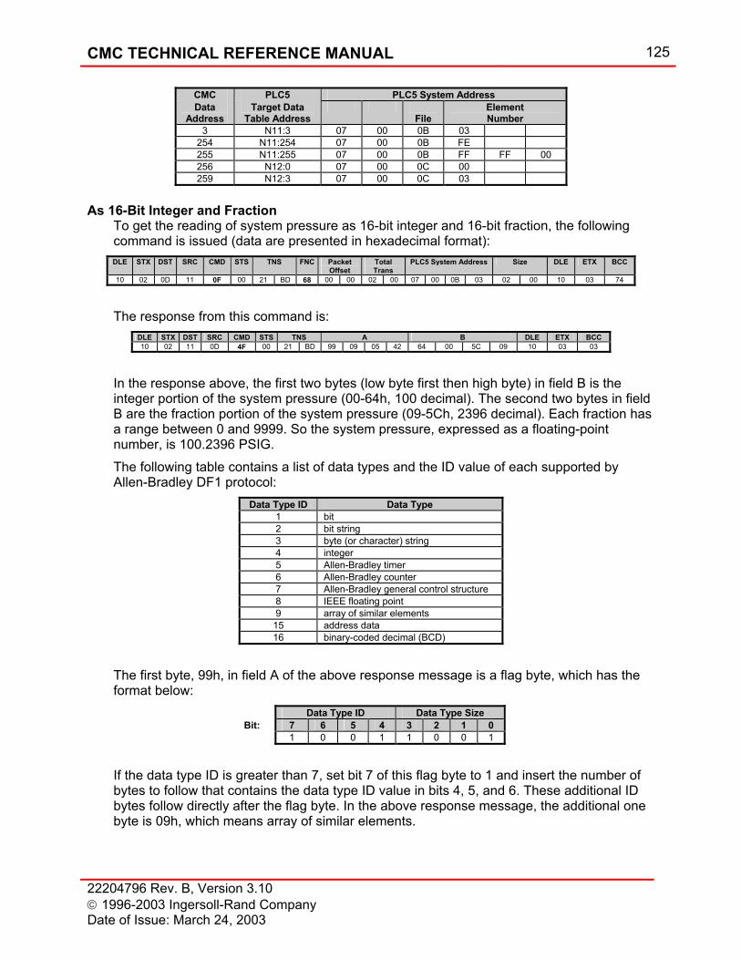
CMC TECHNICAL REFERENCE MANUAL 125
22204796 Rev. B, Version 3.10 1996-2003 Ingersoll-Rand Company Date of Issue: March 24, 2003
As 16-Bit Integer and Fraction
To get the reading of system pressure as 16-bit integer and 16-bit fraction, the following command is issued (data are presented in hexadecimal format): DLE STX DST SRC CMD STS TNS FNC Packet
Offset Total Trans
PLC5 System Address Size DLE ETX BCC
10 02 0D 11 0F 00 21 BD 68 00 00 02 00 07 00 0B 03 02 00 10 03 74
The response from this command is:
DLE STX DST SRC CMD STS TNS A B DLE ETX BCC 10 02 11 0D 4F 00 21 BD 99 09 05 42 64 00 5C 09 10 03 03
In the response above, the first two bytes (low byte first then high byte) in field B is the integer portion of the system pressure (00-64h, 100 decimal). The second two bytes in field B are the fraction portion of the system pressure (09-5Ch, 2396 decimal). Each fraction has a range between 0 and 9999. So the system pressure, expressed as a floating-point number, is 100.2396 PSIG. The following table contains a list of data types and the ID value of each supported by Allen-Bradley DF1 protocol:
Data Type ID Data Type 1 bit 2 bit string 3 byte (or character) string 4 integer 5 Allen-Bradley timer 6 Allen-Bradley counter 7 Allen-Bradley general control structure 8 IEEE floating point 9 array of similar elements 15 address data 16 binary-coded decimal (BCD)
The first byte, 99h, in field A of the above response message is a flag byte, which has the format below:
Data Type ID Data Type Size Bit: 7 6 5 4 3 2 1 0 1 0 0 1 1 0 0 1
If the data type ID is greater than 7, set bit 7 of this flag byte to 1 and insert the number of bytes to follow that contains the data type ID value in bits 4, 5, and 6. These additional ID bytes follow directly after the flag byte. In the above response message, the additional one byte is 09h, which means array of similar elements.
CMC PLC5 PLC5 System Address Data
Address Target Data
Table Address
File Element Number
3 N11:3 07 00 0B 03 254 N11:254 07 00 0B FE 255 N11:255 07 00 0B FF FF 00 256 N12:0 07 00 0C 00 259 N12:3 07 00 0C 03
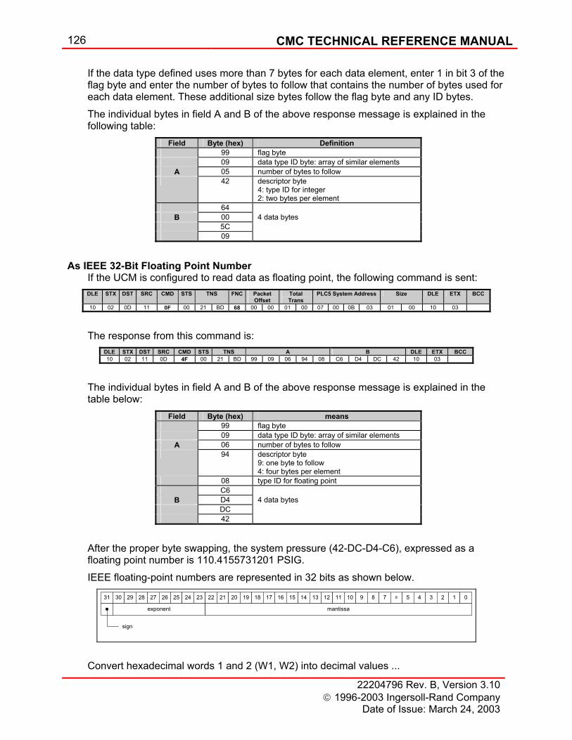
126 CMC TECHNICAL REFERENCE MANUAL
22204796 Rev. B, Version 3.10 1996-2003 Ingersoll-Rand Company
Date of Issue: March 24, 2003
If the data type defined uses more than 7 bytes for each data element, enter 1 in bit 3 of the flag byte and enter the number of bytes to follow that contains the number of bytes used for each data element. These additional size bytes follow the flag byte and any ID bytes. The individual bytes in field A and B of the above response message is explained in the following table:
Field Byte (hex) Definition 99 flag byte 09 data type ID byte: array of similar elements
A 05 number of bytes to follow 42 descriptor byte
4: type ID for integer 2: two bytes per element
64 B 00 4 data bytes 5C 09
As IEEE 32-Bit Floating Point Number If the UCM is configured to read data as floating point, the following command is sent: DLE STX DST SRC CMD STS TNS FNC Packet
Offset Total Trans
PLC5 System Address Size DLE ETX BCC
10 02 0D 11 0F 00 21 BD 68 00 00 01 00 07 00 0B 03 01 00 10 03
The response from this command is:
DLE STX DST SRC CMD STS TNS A B DLE ETX BCC 10 02 11 0D 4F 00 21 BD 99 09 06 94 08 C6 D4 DC 42 10 03
The individual bytes in field A and B of the above response message is explained in the table below:
Field Byte (hex) means 99 flag byte 09 data type ID byte: array of similar elements
A 06 number of bytes to follow 94 descriptor byte
9: one byte to follow 4: four bytes per element
08 type ID for floating point C6
B D4 4 data bytes DC 42
After the proper byte swapping, the system pressure (42-DC-D4-C6), expressed as a floating point number is 110.4155731201 PSIG. IEEE floating-point numbers are represented in 32 bits as shown below.
Convert hexadecimal words 1 and 2 (W1, W2) into decimal values ...
31 30 29 28 27 26 25 24 23 22 21 20 19 18 17 16 15 14 13 12 11 10 9 8 7 6 5 4 3 2 1 0
exponent mantissa
sign
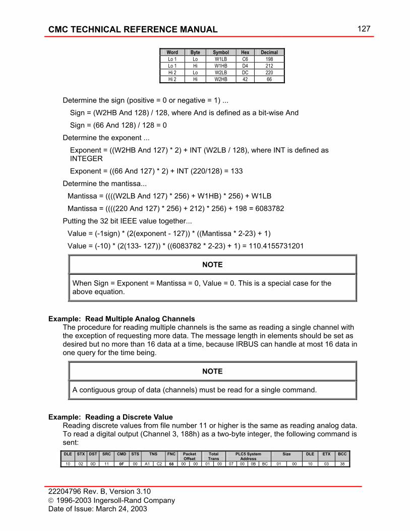
CMC TECHNICAL REFERENCE MANUAL 127
22204796 Rev. B, Version 3.10 1996-2003 Ingersoll-Rand Company Date of Issue: March 24, 2003
Determine the sign (positive = 0 or negative = 1) ...
Sign = (W2HB And 128) / 128, where And is defined as a bit-wise And Sign = (66 And 128) / 128 = 0
Determine the exponent ... Exponent = ((W2HB And 127) * 2) + INT (W2LB / 128), where INT is defined as INTEGER Exponent = ((66 And 127) * 2) + INT (220/128) = 133
Determine the mantissa... Mantissa = ((((W2LB And 127) * 256) + W1HB) * 256) + W1LB Mantissa = ((((220 And 127) * 256) + 212) * 256) + 198 = 6083782
Putting the 32 bit IEEE value together... Value = (-1sign) * (2(exponent - 127)) * ((Mantissa * 2-23) + 1) Value = (-10) * (2(133- 127)) * ((6083782 * 2-23) + 1) = 110.4155731201
NOTE
When Sign = Exponent = Mantissa = 0, Value = 0. This is a special case for the above equation.
Example: Read Multiple Analog Channels The procedure for reading multiple channels is the same as reading a single channel with the exception of requesting more data. The message length in elements should be set as desired but no more than 16 data at a time, because IRBUS can handle at most 16 data in one query for the time being.
NOTE
A contiguous group of data (channels) must be read for a single command.
Example: Reading a Discrete Value Reading discrete values from file number 11 or higher is the same as reading analog data. To read a digital output (Channel 3, 188h) as a two-byte integer, the following command is sent: DLE STX DST SRC CMD STS TNS FNC Packet
Offset Total Trans
PLC5 System Address
Size DLE ETX BCC
10 02 0D 11 0F 00 A1 C2 68 00 00 01 00 07 00 0B BC 01 00 10 03 38
Word Byte Symbol Hex Decimal Lo 1 Lo W1LB C6 198 Lo 1 Hi W1HB D4 212 Hi 2 Lo W2LB DC 220 Hi 2 Hi W2HB 42 66
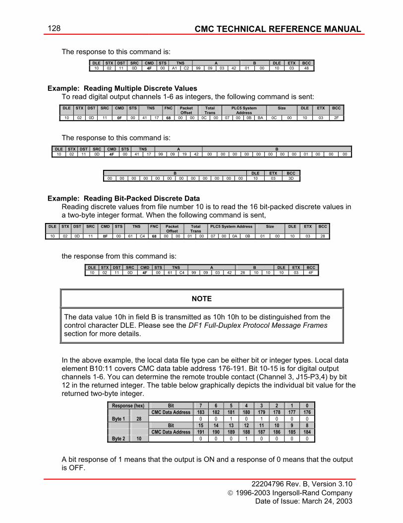
128 CMC TECHNICAL REFERENCE MANUAL
22204796 Rev. B, Version 3.10 1996-2003 Ingersoll-Rand Company
Date of Issue: March 24, 2003
The response to this command is: DLE STX DST SRC CMD STS TNS A B DLE ETX BCC 10 02 11 0D 4F 00 A1 C2 99 09 03 42 01 00 10 03 48
Example: Reading Multiple Discrete Values To read digital output channels 1-6 as integers, the following command is sent: DLE STX DST SRC CMD STS TNS FNC Packet
Offset Total Trans
PLC5 System Address
Size DLE ETX BCC
10 02 0D 11 0F 00 41 17 68 00 00 0C 00 07 00 0B BA 0C 00 10 03 2F
The response to this command is:
DLE STX DST SRC CMD STS TNS A B 10 02 11 0D 4F 00 41 17 99 09 19 42 00 00 00 00 00 00 00 00 01 00 00 00
B DLE ETX BCC
00 00 00 00 00 00 00 00 00 00 00 00 10 03 3D
Example: Reading Bit-Packed Discrete Data Reading discrete values from file number 10 is to read the 16 bit-packed discrete values in a two-byte integer format. When the following command is sent,
DLE STX DST SRC CMD STS TNS FNC Packet Offset
Total Trans
PLC5 System Address Size DLE ETX BCC
10 02 0D 11 0F 00 61 C4 68 00 00 01 00 07 00 0A 0B 01 00 10 03 28
the response from this command is:
DLE STX DST SRC CMD STS TNS A B DLE ETX BCC 10 02 11 0D 4F 00 61 C4 99 09 03 42 28 10 10 10 03 4F
NOTE
The data value 10h in field B is transmitted as 10h 10h to be distinguished from the control character DLE. Please see the DF1 Full-Duplex Protocol Message Frames section for more details.
In the above example, the local data file type can be either bit or integer types. Local data element B10:11 covers CMC data table address 176-191. Bit 10-15 is for digital output channels 1-6. You can determine the remote trouble contact (Channel 3, J15-P3,4) by bit 12 in the returned integer. The table below graphically depicts the individual bit value for the returned two-byte integer.
A bit response of 1 means that the output is ON and a response of 0 means that the output is OFF.
Response (hex) Bit 7 6 5 4 3 2 1 0 CMC Data Address 183 182 181 180 179 178 177 176
Byte 1 28 0 0 1 0 1 0 0 0 Bit 15 14 13 12 11 10 9 8 CMC Data Address 191 190 189 188 187 186 185 184
Byte 2 10 0 0 0 1 0 0 0 0
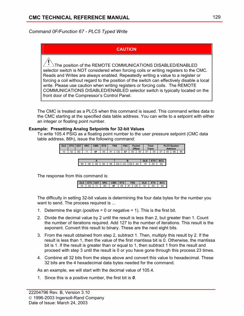
CMC TECHNICAL REFERENCE MANUAL 129
22204796 Rev. B, Version 3.10 1996-2003 Ingersoll-Rand Company Date of Issue: March 24, 2003
Command 0F/Function 67 - PLC5 Typed Write
CAUTION
The position of the REMOTE COMMUNICATIONS DISABLED/ENABLED selector switch is NOT considered when forcing coils or writing registers to the CMC. Reads and Writes are always enabled. Repeatedly writing a value to a register or forcing a coil without regard to the position of the switch can effectively disable a local write. Please use caution when writing registers or forcing coils. The REMOTE COMMUNICATIONS DISABLED/ENABLED selector switch is typically located on the front door of the Compressor’s Control Panel.
The CMC is treated as a PLC5 when this command is issued. This command writes data to the CMC starting at the specified data table address. You can write to a setpoint with either an integer or floating point number.
Example: Presetting Analog Setpoints for 32-bit Values To write 105.4 PSIG as a floating point number to the user pressure setpoint (CMC data table address, 86h), issue the following command:
DLE STX DST SRC CMD STS TNS FNC Packet Offset
Total Trans
PLC5 System Address
10 02 0D 11 0F 00 81 CE 67 00 00 01 00 07 00 0B 86
A B DLE ETX BCC
99 09 06 94 08 CD CC D2 42 10 03 93
The response from this command is:
DLE STX DST SRC CMD STS TNS DLE ETX BCC 10 02 11 0D 4F 00 81 CE 10 03 44
The difficulty in setting 32-bit values is determining the four data bytes for the number you want to send. The process required is ... 1. Determine the sign (positive = 0 or negative = 1). This is the first bit. 2. Divide the decimal value by 2 until the result is less than 2, but greater than 1. Count
the number of iterations required. Add 127 to the number of iterations. This result is the exponent. Convert this result to binary. These are the next eight bits.
3. From the result obtained from step 2, subtract 1. Then, multiply this result by 2. If the result is less than 1, then the value of the first mantissa bit is 0. Otherwise, the mantissa bit is 1. If the result is greater than or equal to 1, then subtract 1 from the result and proceed with step 3 until the result is 0 or you have gone through this process 23 times.
4. Combine all 32 bits from the steps above and convert this value to hexadecimal. These 32 bits are the 4 hexadecimal data bytes needed for the command.
As an example, we will start with the decimal value of 105.4.
1. Since this is a positive number, the first bit is 0.
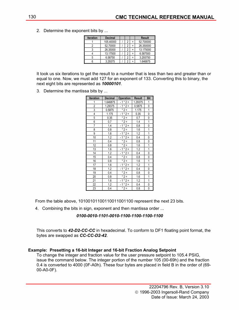
130 CMC TECHNICAL REFERENCE MANUAL
22204796 Rev. B, Version 3.10 1996-2003 Ingersoll-Rand Company
Date of Issue: March 24, 2003
2. Determine the exponent bits by ...
It took us six iterations to get the result to a number that is less than two and greater than or equal to one. Now, we must add 127 for an exponent of 133. Converting this to binary, the next eight bits are represented as 10000101. 3. Determine the mantissa bits by ...
From the table above, 10100101100110011001100 represent the next 23 bits. 4. Combining the bits in sign, exponent and then mantissa order ...
0100-0010-1101-0010-1100-1100-1100-1100
This converts to 42-D2-CC-CC in hexadecimal. To conform to DF1 floating point format, the bytes are swapped as CC-CC-D2-42.
Example: Presetting a 16-bit Integer and 16-bit Fraction Analog Setpoint To change the integer and fraction value for the user pressure setpoint to 105.4 PSIG, issue the command below. The integer portion of the number 105 (00-69h) and the fraction 0.4 is converted to 4000 (0F-A0h). These four bytes are placed in field B in the order of (69-00-A0-0F).
Iteration Decimal Result 1 105.40000 / 2 = 52.700000 2 52.70000 / 2 = 26.350000 3 26.35000 / 2 = 13.175000 4 13.17500 / 2 = 6.587500 5 6.58750 / 2 = 3.293750 6 3.29375 / 2 = 1.646875
Iteration Decimal Operation Result Bit 1 1.646875 - 1 * 2 = 1.29375 1 2 1.29375 - 1 * 2 = 0.5875 0 3 0.5875 * 2 = 1.175 1 4 1.175 - 1 * 2 = 0.35 0 5 0.35 * 2 = 0.7 0 6 0.7 * 2 = 1.4 1 7 1.4 - 1 * 2 = 0.8 0 8 0.8 * 2 = 1.6 1 9 1.6 - 1 * 2 = 1.2 1 10 1.2 - 1 * 2 = 0.4 0 11 0.4 * 2 = 0.8 0 12 0.8 * 2 = 1.6 1 13 1.6 - 1 * 2 = 1.2 1 14 1.2 - 1 * 2 = 0.4 0 15 0.4 * 2 = 0.8 0 16 0.8 * 2 = 1.6 1 17 1.6 - 1 * 2 = 1.2 1 18 1.2 - 1 * 2 = 0.4 0 19 0.4 * 2 = 0.8 0 20 0.8 * 2 = 1.6 1 21 1.6 - 1 * 2 = 1.2 1 22 1.2 - 1 * 2 = 0.4 0 23 0.4 * 2 = 0.8 0
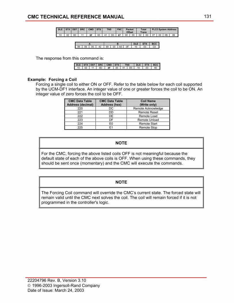
CMC TECHNICAL REFERENCE MANUAL 131
22204796 Rev. B, Version 3.10 1996-2003 Ingersoll-Rand Company Date of Issue: March 24, 2003
DLE STX DST SRC CMD STS TNS FNC Packet Offset
Total Trans
PLC5 System Address
10 02 0D 11 0F 00 41 D0 67 00 00 02 00 07 00 0B 86
A B DLE ETX BCC
99 09 05 42 69 00 A0 0F 10 03 C0
The response from this command is:
DLE STX DST SRC CMD STS TNS DLE ETX BCC 10 02 11 0D 4F 00 41 D0 10 03 82
Example: Forcing a Coil Forcing a single coil to either ON or OFF. Refer to the table below for each coil supported by the UCM-DF1 interface. An integer value of one or greater forces the coil to be ON. An integer value of zero forces the coil to be OFF.
CMC Data Table Address (decimal)
CMC Data Table Address (hex)
Coil Name (Write only)
220 DC Remote Acknowledge 221 DD Remote Reset 222 DE Remote Load 223 DF Remote Unload 224 E0 Remote Start 225 E1 Remote Stop
NOTE
For the CMC, forcing the above listed coils OFF is not meaningful because the default state of each of the above coils is OFF. When using these commands, they should be sent once (momentary) and the CMC will execute the commands.
NOTE
The Forcing Coil command will override the CMC’s current state. The forced state will remain valid until the CMC next solves the coil. The coil will remain forced if it is not programmed in the controller's logic.
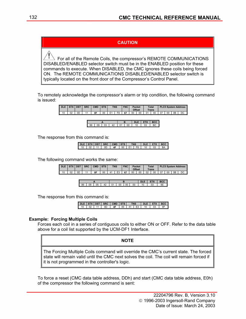
132 CMC TECHNICAL REFERENCE MANUAL
22204796 Rev. B, Version 3.10 1996-2003 Ingersoll-Rand Company
Date of Issue: March 24, 2003
CAUTION
For all of the Remote Coils, the compressor’s REMOTE COMMUNICATIONS DISABLED/ENABLED selector switch must be in the ENABLED position for these commands to execute. When DISABLED, the CMC ignores these coils being forced ON. The REMOTE COMMUNICATIONS DISABLED/ENABLED selector switch is typically located on the front door of the Compressor’s Control Panel.
To remotely acknowledge the compressor’s alarm or trip condition, the following command is issued:
DLE STX DST SRC CMD STS TNS FNC Packet Offset
Total Trans
PLC5 System Address
10 02 0D 11 0F 00 E1 F8 67 00 00 01 00 07 00 0B DC
A B DLE ETX BCC
99 09 03 42 01 00 10 03 BC
The response from this command is:
DLE STX DST SRC CMD STS TNS DLE ETX BCC 10 02 11 0D 4F 00 E1 F8 10 03 BA
The following command works the same:
DLE STX DST SRC CMD STS TNS FNC Packet Offset
Total Trans
PLC5 System Address
10 02 0D 11 0F 00 41 E3 67 00 00 02 00 07 00 0B DC
A B DLE ETX BCC
99 09 05 42 01 00 00 00 10 03 6E
The response from this command is:
DLE STX DST SRC CMD STS TNS DLE ETX BCC 10 02 11 0D 4F 00 41 E3 10 03 6F
Example: Forcing Multiple Coils Forces each coil in a series of contiguous coils to either ON or OFF. Refer to the data table above for a coil list supported by the UCM-DF1 Interface.
NOTE
The Forcing Multiple Coils command will override the CMC’s current state. The forced state will remain valid until the CMC next solves the coil. The coil will remain forced if it is not programmed in the controller's logic.
To force a reset (CMC data table address, DDh) and start (CMC data table address, E0h) of the compressor the following command is sent:
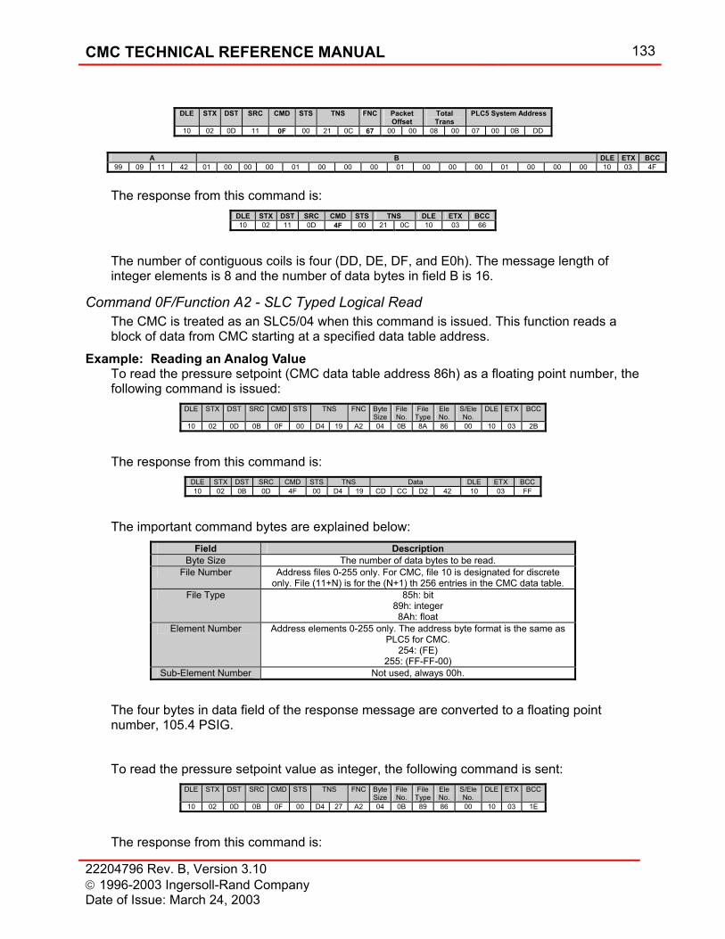
CMC TECHNICAL REFERENCE MANUAL 133
22204796 Rev. B, Version 3.10 1996-2003 Ingersoll-Rand Company Date of Issue: March 24, 2003
DLE STX DST SRC CMD STS TNS FNC Packet
Offset Total Trans
PLC5 System Address
10 02 0D 11 0F 00 21 0C 67 00 00 08 00 07 00 0B DD
A B DLE ETX BCC
99 09 11 42 01 00 00 00 01 00 00 00 01 00 00 00 01 00 00 00 10 03 4F
The response from this command is:
DLE STX DST SRC CMD STS TNS DLE ETX BCC 10 02 11 0D 4F 00 21 0C 10 03 66
The number of contiguous coils is four (DD, DE, DF, and E0h). The message length of integer elements is 8 and the number of data bytes in field B is 16.
Command 0F/Function A2 - SLC Typed Logical Read The CMC is treated as an SLC5/04 when this command is issued. This function reads a block of data from CMC starting at a specified data table address.
Example: Reading an Analog Value To read the pressure setpoint (CMC data table address 86h) as a floating point number, the following command is issued:
DLE STX DST SRC CMD STS TNS FNC ByteSize
File No.
File Type
Ele No.
S/Ele No.
DLE ETX BCC
10 02 0D 0B 0F 00 D4 19 A2 04 0B 8A 86 00 10 03 2B
The response from this command is:
DLE STX DST SRC CMD STS TNS Data DLE ETX BCC 10 02 0B 0D 4F 00 D4 19 CD CC D2 42 10 03 FF
The important command bytes are explained below:
Field Description Byte Size The number of data bytes to be read.
File Number Address files 0-255 only. For CMC, file 10 is designated for discrete only. File (11+N) is for the (N+1) th 256 entries in the CMC data table.
File Type 85h: bit 89h: integer 8Ah: float
Element Number Address elements 0-255 only. The address byte format is the same as PLC5 for CMC.
254: (FE) 255: (FF-FF-00)
Sub-Element Number Not used, always 00h.
The four bytes in data field of the response message are converted to a floating point number, 105.4 PSIG. To read the pressure setpoint value as integer, the following command is sent:
DLE STX DST SRC CMD STS TNS FNC ByteSize
File No.
File Type
Ele No.
S/Ele No.
DLE ETX BCC
10 02 0D 0B 0F 00 D4 27 A2 04 0B 89 86 00 10 03 1E
The response from this command is:
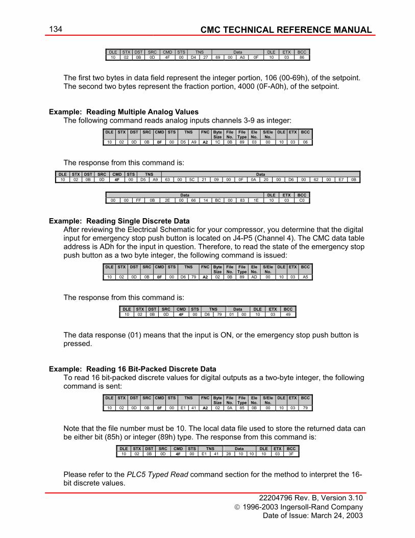
134 CMC TECHNICAL REFERENCE MANUAL
22204796 Rev. B, Version 3.10 1996-2003 Ingersoll-Rand Company
Date of Issue: March 24, 2003
DLE STX DST SRC CMD STS TNS Data DLE ETX BCC 10 02 0B 0D 4F 00 D4 27 69 00 A0 0F 10 03 86
The first two bytes in data field represent the integer portion, 106 (00-69h), of the setpoint. The second two bytes represent the fraction portion, 4000 (0F-A0h), of the setpoint.
Example: Reading Multiple Analog Values The following command reads analog inputs channels 3-9 as integer:
DLE STX DST SRC CMD STS TNS FNC ByteSize
File No.
File Type
Ele No.
S/Ele No.
DLE ETX BCC
10 02 0D 0B 0F 00 D5 A9 A2 1C 0B 89 03 00 10 03 06
The response from this command is:
DLE STX DST SRC CMD STS TNS Data 10 02 0B 0D 4F 00 D5 A9 63 00 5C 21 09 00 0F 0A 20 00 D6 00 62 00 E7 0B
Data DLE ETX BCC
00 00 FF 0B 2E 00 66 14 BC 00 83 1E 10 03 C0
Example: Reading Single Discrete Data After reviewing the Electrical Schematic for your compressor, you determine that the digital input for emergency stop push button is located on J4-P5 (Channel 4). The CMC data table address is ADh for the input in question. Therefore, to read the state of the emergency stop push button as a two byte integer, the following command is issued:
DLE STX DST SRC CMD STS TNS FNC ByteSize
File No.
File Type
Ele No.
S/Ele No.
DLE ETX BCC
10 02 0D 0B 0F 00 D6 79 A2 02 0B 89 AD 00 10 03 A5
The response from this command is:
DLE STX DST SRC CMD STS TNS Data DLE ETX BCC 10 02 0B 0D 4F 00 D6 79 01 00 10 03 49
The data response (01) means that the input is ON, or the emergency stop push button is pressed.
Example: Reading 16 Bit-Packed Discrete Data To read 16 bit-packed discrete values for digital outputs as a two-byte integer, the following command is sent:
DLE STX DST SRC CMD STS TNS FNC ByteSize
File No.
File Type
Ele No.
S/Ele No.
DLE ETX BCC
10 02 0D 0B 0F 00 E1 41 A2 02 0A 85 0B 00 10 03 79
Note that the file number must be 10. The local data file used to store the returned data can be either bit (85h) or integer (89h) type. The response from this command is:
DLE STX DST SRC CMD STS TNS Data DLE ETX BCC 10 02 0B 0D 4F 00 E1 41 28 10 10 10 03 3F
Please refer to the PLC5 Typed Read command section for the method to interpret the 16-bit discrete values.
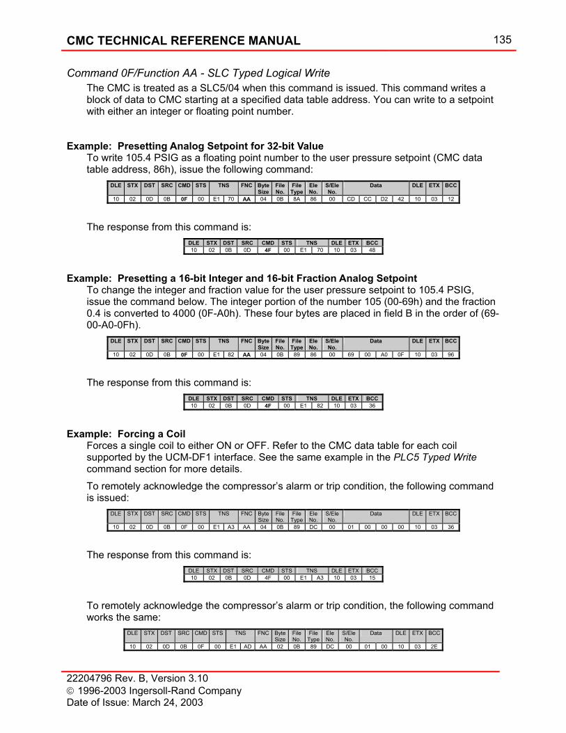
CMC TECHNICAL REFERENCE MANUAL 135
22204796 Rev. B, Version 3.10 1996-2003 Ingersoll-Rand Company Date of Issue: March 24, 2003
Command 0F/Function AA - SLC Typed Logical Write The CMC is treated as a SLC5/04 when this command is issued. This command writes a block of data to CMC starting at a specified data table address. You can write to a setpoint with either an integer or floating point number.
Example: Presetting Analog Setpoint for 32-bit Value To write 105.4 PSIG as a floating point number to the user pressure setpoint (CMC data table address, 86h), issue the following command:
DLE STX DST SRC CMD STS TNS FNC ByteSize
File No.
File Type
Ele No.
S/Ele No.
Data DLE ETX BCC
10 02 0D 0B 0F 00 E1 70 AA 04 0B 8A 86 00 CD CC D2 42 10 03 12
The response from this command is:
DLE STX DST SRC CMD STS TNS DLE ETX BCC 10 02 0B 0D 4F 00 E1 70 10 03 48
Example: Presetting a 16-bit Integer and 16-bit Fraction Analog Setpoint To change the integer and fraction value for the user pressure setpoint to 105.4 PSIG, issue the command below. The integer portion of the number 105 (00-69h) and the fraction 0.4 is converted to 4000 (0F-A0h). These four bytes are placed in field B in the order of (69-00-A0-0Fh).
DLE STX DST SRC CMD STS TNS FNC ByteSize
File No.
File Type
Ele No.
S/Ele No.
Data DLE ETX BCC
10 02 0D 0B 0F 00 E1 82 AA 04 0B 89 86 00 69 00 A0 0F 10 03 96
The response from this command is:
DLE STX DST SRC CMD STS TNS DLE ETX BCC 10 02 0B 0D 4F 00 E1 82 10 03 36
Example: Forcing a Coil Forces a single coil to either ON or OFF. Refer to the CMC data table for each coil supported by the UCM-DF1 interface. See the same example in the PLC5 Typed Write command section for more details. To remotely acknowledge the compressor’s alarm or trip condition, the following command is issued:
DLE STX DST SRC CMD STS TNS FNC ByteSize
File No.
File Type
Ele No.
S/Ele No.
Data DLE ETX BCC
10 02 0D 0B 0F 00 E1 A3 AA 04 0B 89 DC 00 01 00 00 00 10 03 36
The response from this command is:
DLE STX DST SRC CMD STS TNS DLE ETX BCC 10 02 0B 0D 4F 00 E1 A3 10 03 15
To remotely acknowledge the compressor’s alarm or trip condition, the following command works the same:
DLE STX DST SRC CMD STS TNS FNC ByteSize
File No.
File Type
Ele No.
S/Ele No.
Data DLE ETX BCC
10 02 0D 0B 0F 00 E1 AD AA 02 0B 89 DC 00 01 00 10 03 2E
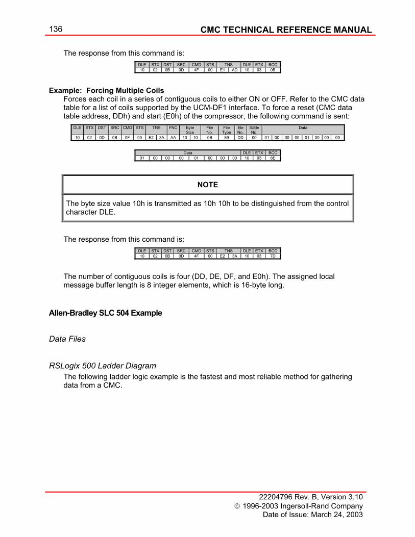
136 CMC TECHNICAL REFERENCE MANUAL
22204796 Rev. B, Version 3.10 1996-2003 Ingersoll-Rand Company
Date of Issue: March 24, 2003
The response from this command is: DLE STX DST SRC CMD STS TNS DLE ETX BCC 10 02 0B 0D 4F 00 E1 AD 10 03 0B
Example: Forcing Multiple Coils Forces each coil in a series of contiguous coils to either ON or OFF. Refer to the CMC data table for a list of coils supported by the UCM-DF1 interface. To force a reset (CMC data table address, DDh) and start (E0h) of the compressor, the following command is sent:
DLE STX DST SRC CMD STS TNS FNC Byte Size
File No.
File Type
Ele No.
S/Ele No.
Data
10 02 0D 0B 0F 00 E2 3A AA 10 10 0B 89 DD 00 01 00 00 00 01 00 00 00
Data DLE ETX BCC
01 00 00 00 01 00 00 00 10 03 8E
NOTE
The byte size value 10h is transmitted as 10h 10h to be distinguished from the control character DLE.
The response from this command is:
DLE STX DST SRC CMD STS TNS DLE ETX BCC 10 02 0B 0D 4F 00 E2 3A 10 03 7D
The number of contiguous coils is four (DD, DE, DF, and E0h). The assigned local message buffer length is 8 integer elements, which is 16-byte long.
Allen-Bradley SLC 504 Example
Data Files
RSLogix 500 Ladder Diagram The following ladder logic example is the fastest and most reliable method for gathering data from a CMC.
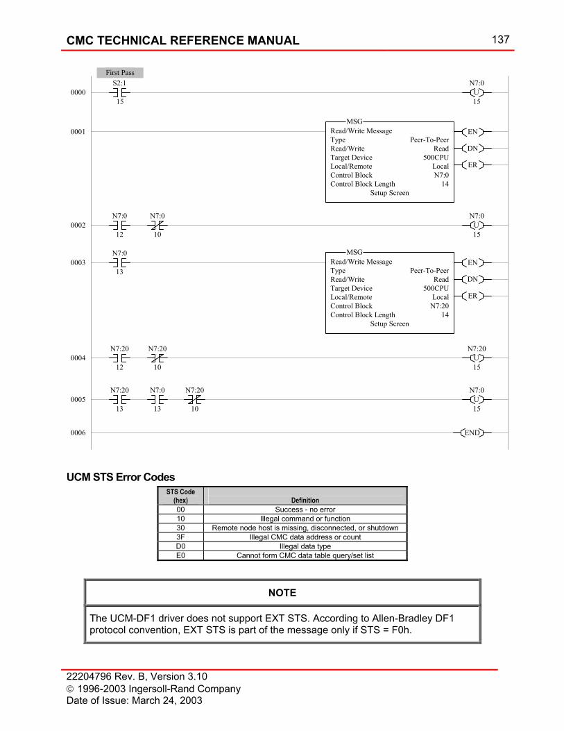
CMC TECHNICAL REFERENCE MANUAL 137
22204796 Rev. B, Version 3.10 1996-2003 Ingersoll-Rand Company Date of Issue: March 24, 2003
UCM STS Error Codes STS Code
(hex)
Definition 00 Success - no error 10 Illegal command or function 30 Remote node host is missing, disconnected, or shutdown 3F Illegal CMC data address or count D0 Illegal data type E0 Cannot form CMC data table query/set list
NOTE
The UCM-DF1 driver does not support EXT STS. According to Allen-Bradley DF1 protocol convention, EXT STS is part of the message only if STS = F0h.
N7:0U15
U15
N7:0First Pass
S2:1
150000
EN
DN
ER
MSGRead/Write MessageTypeRead/WriteTarget DeviceLocal/RemoteControl BlockControl Block Length
Setup Screen
Peer-To-PeerRead
500CPULocalN7:0
14
0001
N7:0
120002
N7:0
10
EN
DN
ER
MSGRead/Write MessageTypeRead/WriteTarget DeviceLocal/RemoteControl BlockControl Block Length
Setup Screen
Peer-To-PeerRead
500CPULocal
N7:2014
0003N7:0
13
N7:20U15
N7:20
120004
N7:20
10
N7:0U15
N7:20
130005
N7:20
10
N7:0
13
END0006
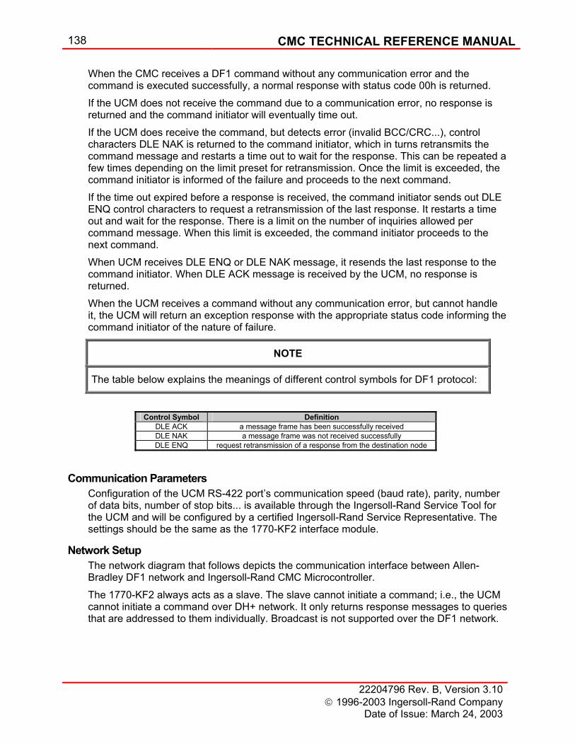
138 CMC TECHNICAL REFERENCE MANUAL
22204796 Rev. B, Version 3.10 1996-2003 Ingersoll-Rand Company
Date of Issue: March 24, 2003
When the CMC receives a DF1 command without any communication error and the command is executed successfully, a normal response with status code 00h is returned. If the UCM does not receive the command due to a communication error, no response is returned and the command initiator will eventually time out. If the UCM does receive the command, but detects error (invalid BCC/CRC...), control characters DLE NAK is returned to the command initiator, which in turns retransmits the command message and restarts a time out to wait for the response. This can be repeated a few times depending on the limit preset for retransmission. Once the limit is exceeded, the command initiator is informed of the failure and proceeds to the next command. If the time out expired before a response is received, the command initiator sends out DLE ENQ control characters to request a retransmission of the last response. It restarts a time out and wait for the response. There is a limit on the number of inquiries allowed per command message. When this limit is exceeded, the command initiator proceeds to the next command. When UCM receives DLE ENQ or DLE NAK message, it resends the last response to the command initiator. When DLE ACK message is received by the UCM, no response is returned. When the UCM receives a command without any communication error, but cannot handle it, the UCM will return an exception response with the appropriate status code informing the command initiator of the nature of failure.
NOTE
The table below explains the meanings of different control symbols for DF1 protocol:
Control Symbol Definition
DLE ACK a message frame has been successfully received DLE NAK a message frame was not received successfully DLE ENQ request retransmission of a response from the destination node
Communication Parameters Configuration of the UCM RS-422 port’s communication speed (baud rate), parity, number of data bits, number of stop bits... is available through the Ingersoll-Rand Service Tool for the UCM and will be configured by a certified Ingersoll-Rand Service Representative. The settings should be the same as the 1770-KF2 interface module.
Network Setup The network diagram that follows depicts the communication interface between Allen-Bradley DF1 network and Ingersoll-Rand CMC Microcontroller. The 1770-KF2 always acts as a slave. The slave cannot initiate a command; i.e., the UCM cannot initiate a command over DH+ network. It only returns response messages to queries that are addressed to them individually. Broadcast is not supported over the DF1 network.
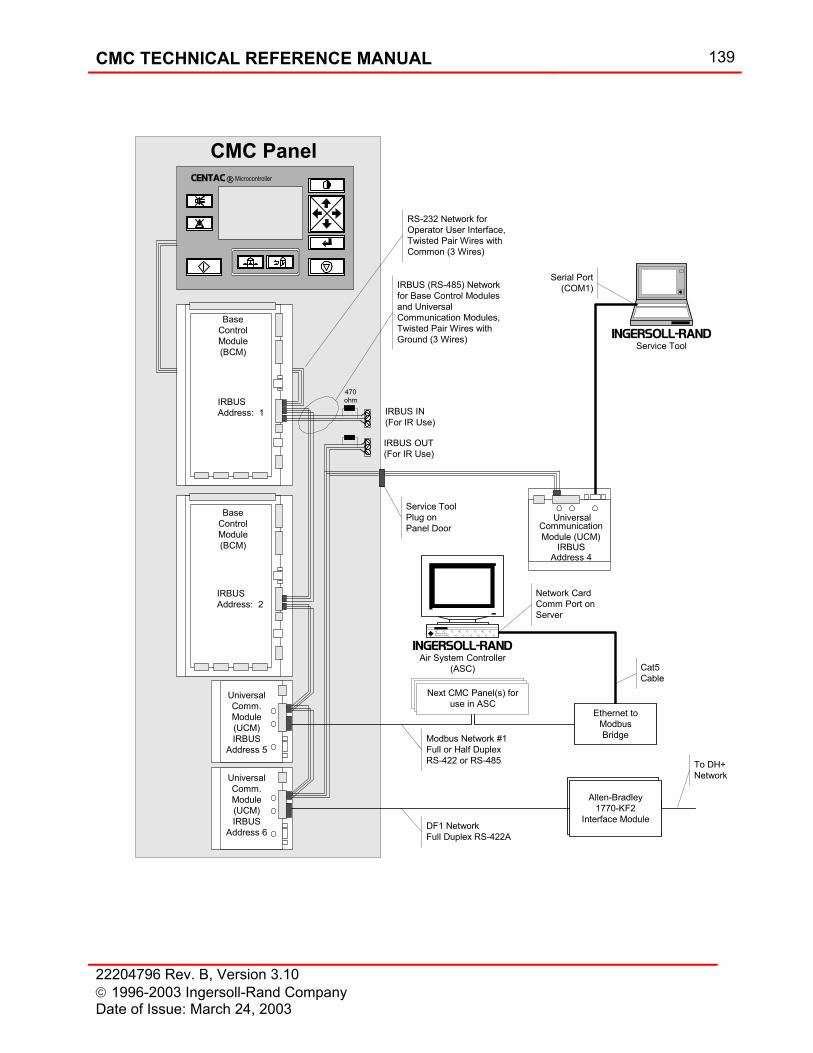
CMC TECHNICAL REFERENCE MANUAL 139
22204796 Rev. B, Version 3.10 1996-2003 Ingersoll-Rand Company Date of Issue: March 24, 2003
UniversalCommunicationModule (UCM)
IRBUS (RS-485) Networkfor Base Control Modulesand UniversalCommunication Modules,Twisted Pair Wires withGround (3 Wires)
Allen-Bradley1770-KF2
Interface Module
INGERSOLL-RANDService Tool
Ethernet toModbusBridge
UniversalComm.Module(UCM)IRBUS
Address 5
IRBUSAddress: 2
BaseControlModule(BCM)
IRBUSAddress: 1
CENTAC Microcontroller
CMC Panel
Serial Port(COM1)
Service ToolPlug onPanel Door
Cat5Cable
Network CardComm Port onServer
Modbus Network #1Full or Half DuplexRS-422 or RS-485
INGERSOLL-RANDAir System Controller
(ASC)
DF1 NetworkFull Duplex RS-422A
BaseControlModule(BCM)
Next CMC Panel(s) foruse in ASC
IRBUSAddress 4
UniversalComm.Module(UCM)IRBUS
Address 6
470ohm
IRBUS IN(For IR Use)
IRBUS OUT(For IR Use)
RS-232 Network forOperator User Interface,Twisted Pair Wires withCommon (3 Wires)
To DH+Network
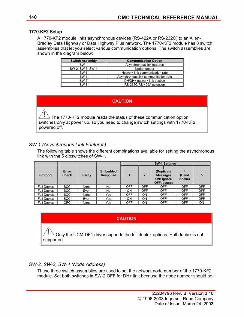
140 CMC TECHNICAL REFERENCE MANUAL
22204796 Rev. B, Version 3.10 1996-2003 Ingersoll-Rand Company
Date of Issue: March 24, 2003
1770-KF2 Setup A 1770-KF2 module links asynchronous devices (RS-422A or RS-232C) to an Allen-Bradley Data Highway or Data Highway Plus network. The 1770-KF2 module has 8 switch assemblies that let you select various communication options. The switch assemblies are shown in the diagram below:
Switch Assembly Communication Option SW-1 Asynchronous link features
SW-2, SW-3, SW-4 Node number SW-5 Network link communication rate SW-6 Asynchronous link communication rate SW-7 DH/DH+ network link section SW-8 RS-232C/RS-422A selection
CAUTION
The 1770-KF2 module reads the status of these communication option switches only at power up, so you need to change switch settings with 1770-KF2 powered off.
SW-1 (Asynchronous Link Features) The following table shows the different combinations available for setting the asynchronous link with the 5 dipswitches of SW-1.
SW-1 Settings
Protocol
Error Check
Parity
Embedded Response
1
2
3 (Duplicate Message)
ON: ignore OFF: accept
4
(Hand Shake)
5
Full Duplex BCC None No OFF OFF OFF OFF OFF Full Duplex BCC Even No ON OFF OFF OFF OFF Full Duplex BCC None Yes OFF ON OFF OFF OFF Full Duplex BCC Even Yes ON ON OFF OFF OFF Full Duplex CRC None Yes OFF ON OFF OFF ON
CAUTION
Only the UCM-DF1 driver supports the full duplex options. Half duplex is not supported.
SW-2, SW-3, SW-4 (Node Address) These three switch assemblies are used to set the network node number of the 1770-KF2 module. Set both switches in SW-2 OFF for DH+ link because the node number should be
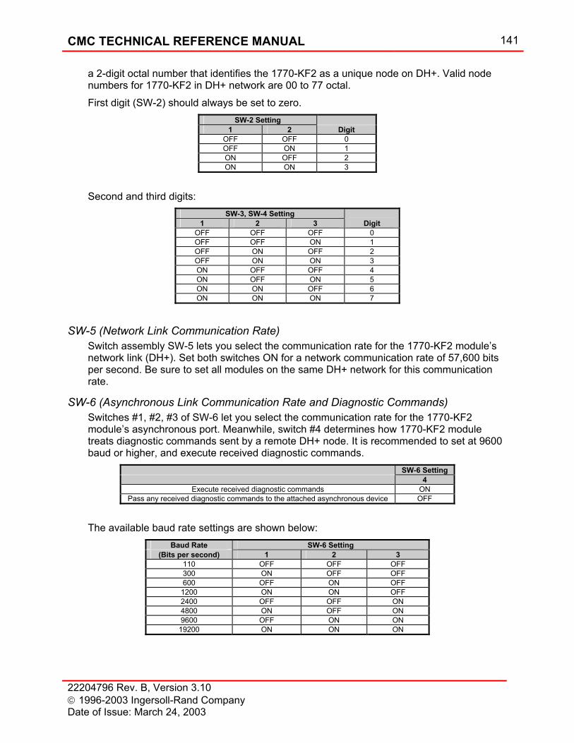
CMC TECHNICAL REFERENCE MANUAL 141
22204796 Rev. B, Version 3.10 1996-2003 Ingersoll-Rand Company Date of Issue: March 24, 2003
a 2-digit octal number that identifies the 1770-KF2 as a unique node on DH+. Valid node numbers for 1770-KF2 in DH+ network are 00 to 77 octal. First digit (SW-2) should always be set to zero.
SW-2 Setting 1 2 Digit
OFF OFF 0 OFF ON 1 ON OFF 2 ON ON 3
Second and third digits:
SW-3, SW-4 Setting 1 2 3 Digit
OFF OFF OFF 0 OFF OFF ON 1 OFF ON OFF 2 OFF ON ON 3 ON OFF OFF 4 ON OFF ON 5 ON ON OFF 6 ON ON ON 7
SW-5 (Network Link Communication Rate) Switch assembly SW-5 lets you select the communication rate for the 1770-KF2 module’s network link (DH+). Set both switches ON for a network communication rate of 57,600 bits per second. Be sure to set all modules on the same DH+ network for this communication rate.
SW-6 (Asynchronous Link Communication Rate and Diagnostic Commands) Switches #1, #2, #3 of SW-6 let you select the communication rate for the 1770-KF2 module’s asynchronous port. Meanwhile, switch #4 determines how 1770-KF2 module treats diagnostic commands sent by a remote DH+ node. It is recommended to set at 9600 baud or higher, and execute received diagnostic commands.
SW-6 Setting 4
Execute received diagnostic commands ON Pass any received diagnostic commands to the attached asynchronous device OFF
The available baud rate settings are shown below:
Baud Rate SW-6 Setting (Bits per second) 1 2 3
110 OFF OFF OFF 300 ON OFF OFF 600 OFF ON OFF 1200 ON ON OFF 2400 OFF OFF ON 4800 ON OFF ON 9600 OFF ON ON 19200 ON ON ON
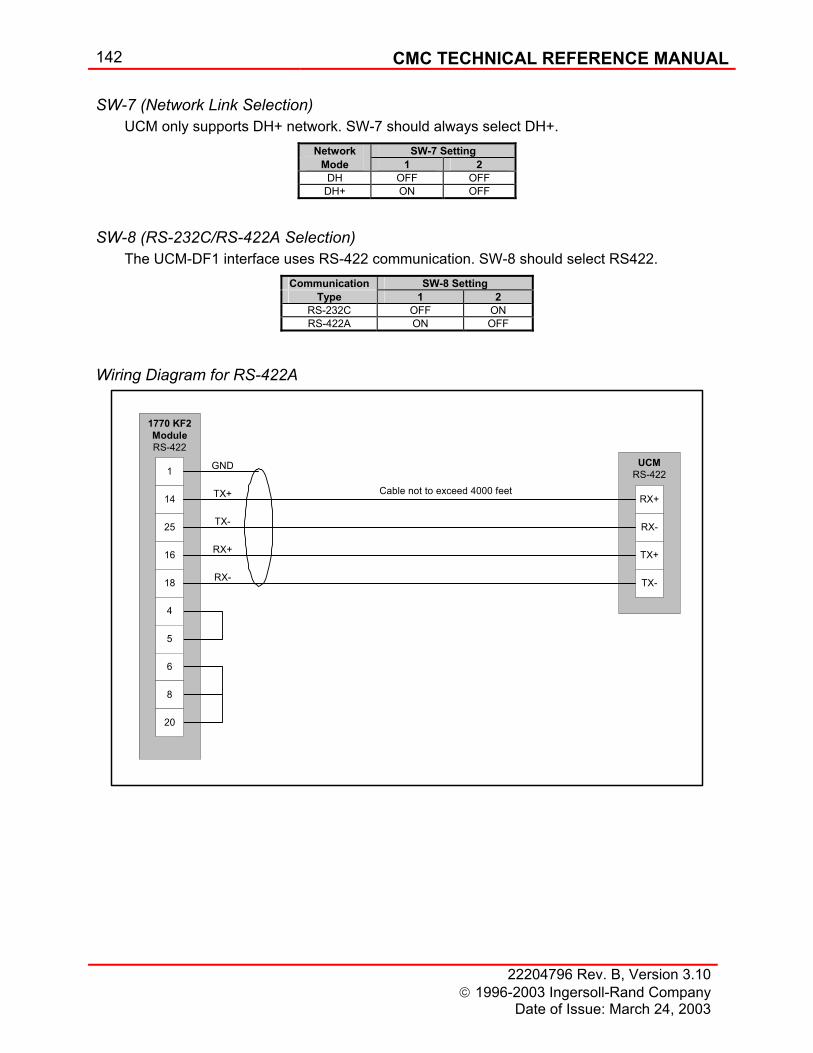
142 CMC TECHNICAL REFERENCE MANUAL
22204796 Rev. B, Version 3.10 1996-2003 Ingersoll-Rand Company
Date of Issue: March 24, 2003
SW-7 (Network Link Selection) UCM only supports DH+ network. SW-7 should always select DH+.
Network SW-7 Setting Mode 1 2
DH OFF OFF DH+ ON OFF
SW-8 (RS-232C/RS-422A Selection) The UCM-DF1 interface uses RS-422 communication. SW-8 should select RS422.
Communication SW-8 Setting Type 1 2
RS-232C OFF ON RS-422A ON OFF
Wiring Diagram for RS-422A
UCMRS-422
1770 KF2ModuleRS-422
1
RX+
RX-
TX+
TX-
14
25
16
18
4
5
6
8
20
TX+
TX-
RX-
RX+
GND
Cable not to exceed 4000 feet
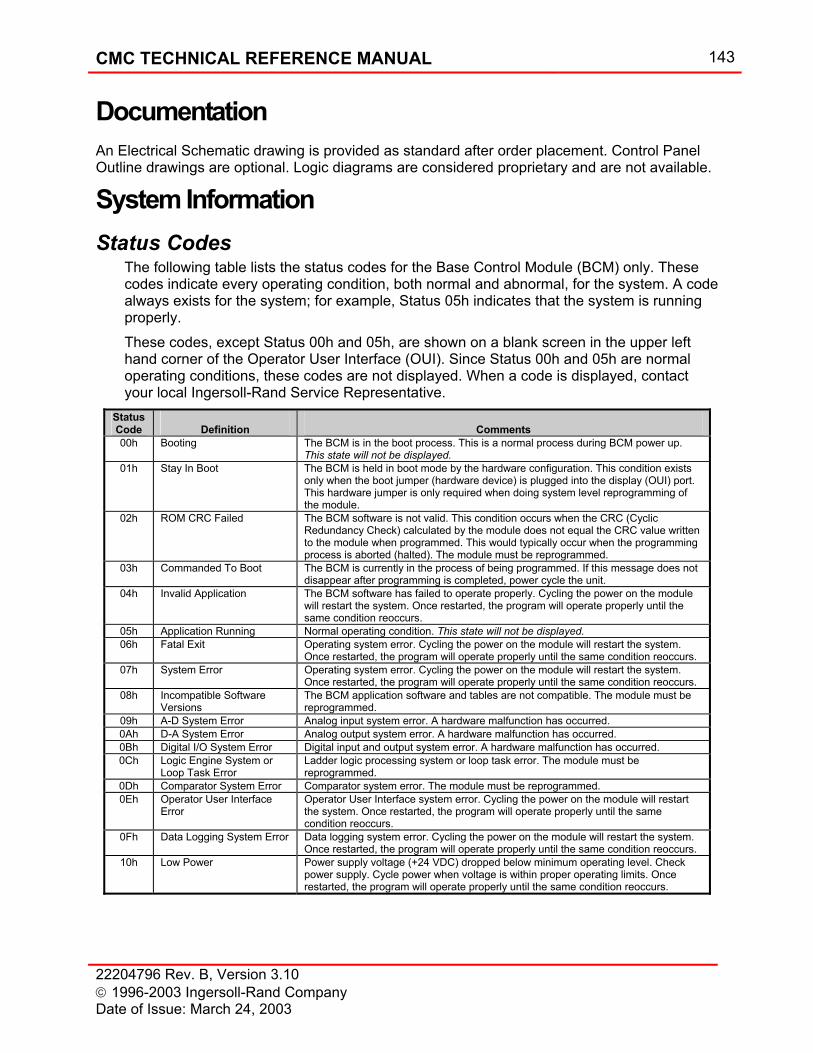
CMC TECHNICAL REFERENCE MANUAL 143
22204796 Rev. B, Version 3.10 1996-2003 Ingersoll-Rand Company Date of Issue: March 24, 2003
Documentation An Electrical Schematic drawing is provided as standard after order placement. Control Panel Outline drawings are optional. Logic diagrams are considered proprietary and are not available.
System Information Status Codes
The following table lists the status codes for the Base Control Module (BCM) only. These codes indicate every operating condition, both normal and abnormal, for the system. A code always exists for the system; for example, Status 05h indicates that the system is running properly. These codes, except Status 00h and 05h, are shown on a blank screen in the upper left hand corner of the Operator User Interface (OUI). Since Status 00h and 05h are normal operating conditions, these codes are not displayed. When a code is displayed, contact your local Ingersoll-Rand Service Representative.
Status Code
Definition
Comments
00h Booting The BCM is in the boot process. This is a normal process during BCM power up. This state will not be displayed.
01h Stay In Boot The BCM is held in boot mode by the hardware configuration. This condition exists only when the boot jumper (hardware device) is plugged into the display (OUI) port. This hardware jumper is only required when doing system level reprogramming of the module.
02h ROM CRC Failed The BCM software is not valid. This condition occurs when the CRC (Cyclic Redundancy Check) calculated by the module does not equal the CRC value written to the module when programmed. This would typically occur when the programming process is aborted (halted). The module must be reprogrammed.
03h Commanded To Boot The BCM is currently in the process of being programmed. If this message does not disappear after programming is completed, power cycle the unit.
04h Invalid Application The BCM software has failed to operate properly. Cycling the power on the module will restart the system. Once restarted, the program will operate properly until the same condition reoccurs.
05h Application Running Normal operating condition. This state will not be displayed. 06h Fatal Exit Operating system error. Cycling the power on the module will restart the system.
Once restarted, the program will operate properly until the same condition reoccurs. 07h System Error Operating system error. Cycling the power on the module will restart the system.
Once restarted, the program will operate properly until the same condition reoccurs. 08h Incompatible Software
Versions The BCM application software and tables are not compatible. The module must be reprogrammed.
09h A-D System Error Analog input system error. A hardware malfunction has occurred. 0Ah D-A System Error Analog output system error. A hardware malfunction has occurred. 0Bh Digital I/O System Error Digital input and output system error. A hardware malfunction has occurred. 0Ch Logic Engine System or
Loop Task Error Ladder logic processing system or loop task error. The module must be reprogrammed.
0Dh Comparator System Error Comparator system error. The module must be reprogrammed. 0Eh Operator User Interface
Error Operator User Interface system error. Cycling the power on the module will restart the system. Once restarted, the program will operate properly until the same condition reoccurs.
0Fh Data Logging System Error Data logging system error. Cycling the power on the module will restart the system. Once restarted, the program will operate properly until the same condition reoccurs.
10h Low Power Power supply voltage (+24 VDC) dropped below minimum operating level. Check power supply. Cycle power when voltage is within proper operating limits. Once restarted, the program will operate properly until the same condition reoccurs.
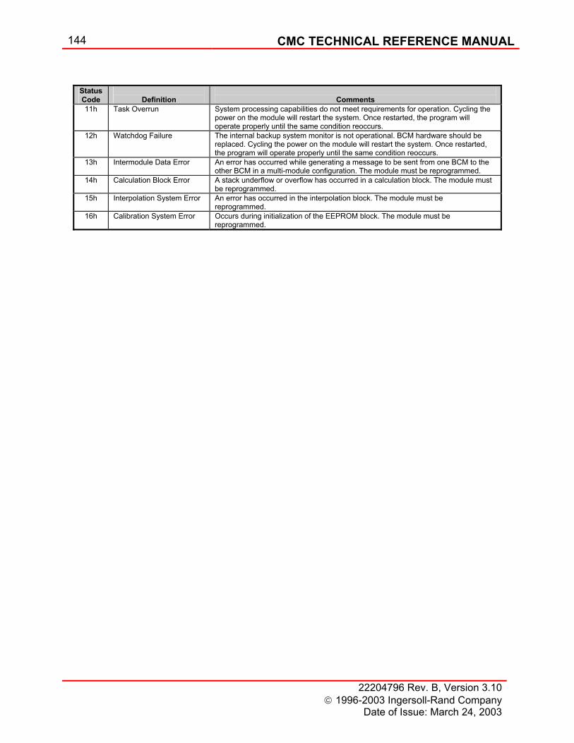
144 CMC TECHNICAL REFERENCE MANUAL
22204796 Rev. B, Version 3.10 1996-2003 Ingersoll-Rand Company
Date of Issue: March 24, 2003
Status Code
Definition
Comments
11h Task Overrun System processing capabilities do not meet requirements for operation. Cycling the power on the module will restart the system. Once restarted, the program will operate properly until the same condition reoccurs.
12h Watchdog Failure The internal backup system monitor is not operational. BCM hardware should be replaced. Cycling the power on the module will restart the system. Once restarted, the program will operate properly until the same condition reoccurs.
13h Intermodule Data Error An error has occurred while generating a message to be sent from one BCM to the other BCM in a multi-module configuration. The module must be reprogrammed.
14h Calculation Block Error A stack underflow or overflow has occurred in a calculation block. The module must be reprogrammed.
15h Interpolation System Error An error has occurred in the interpolation block. The module must be reprogrammed.
16h Calibration System Error Occurs during initialization of the EEPROM block. The module must be reprogrammed.
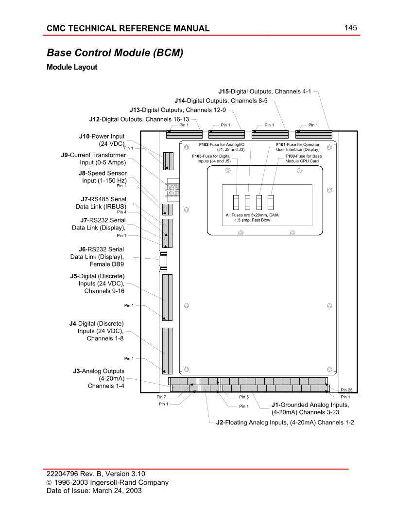
CMC TECHNICAL REFERENCE MANUAL 145
22204796 Rev. B, Version 3.10 1996-2003 Ingersoll-Rand Company Date of Issue: March 24, 2003
Base Control Module (BCM) Module Layout
J3-Analog Outputs(4-20mA)
Channels 1-4Pin 7
Pin 1
J2-Floating Analog Inputs, (4-20mA) Channels 1-2
Pin 1
Pin 5
J1-Grounded Analog Inputs,(4-20mA) Channels 3-23
Pin 1Pin 25
Pin 1
Pin 1
Pin 1
Pin 4
J4-Digital (Discrete)Inputs (24 VDC),
Channels 1-8
J5-Digital (Discrete)Inputs (24 VDC),
Channels 9-16
J6-RS232 SerialData Link (Display),
Female DB9
J7-RS485 SerialData Link (IRBUS)
Pin 1
J8-Speed SensorInput (1-150 Hz)
J9-Current TransformerInput (0-5 Amps)
J12-Digital Outputs, Channels 16-13
J10-Power Input(24 VDC)
J13-Digital Outputs, Channels 12-9J14-Digital Outputs, Channels 8-5
J15-Digital Outputs, Channels 4-1
F102-Fuse for AnalogI/O(J1, J2 and J3)
F101-Fuse for OperatorUser Interface (Display)
F100-Fuse for BaseModule CPU Card
All Fuses are 5x20mm, GMA1.5 amp, Fast Blow
F103-Fuse for DigitalInputs (J4 and J5)
Pin 1 Pin 1 Pin 1 Pin 1
J7-RS232 SerialData Link (Display),
Pin 1
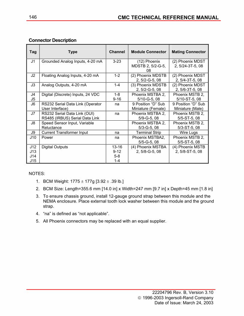
146 CMC TECHNICAL REFERENCE MANUAL
22204796 Rev. B, Version 3.10 1996-2003 Ingersoll-Rand Company
Date of Issue: March 24, 2003
Connector Description
Tag
Type
Channel
Module Connector
Mating Connector
J1 Grounded Analog Inputs, 4-20 mA 3-23 (12) Phoenix MDSTB 2, 5/2-G-5,
08
(2) Phoenix MDST 2, 5/24-3T-5, 08
J2 Floating Analog Inputs, 4-20 mA 1-2 (2) Phoenix MDSTB 2, 5/2-G-5, 08
(2) Phoenix MDST 2, 5/4-3T-5, 08
J3 Analog Outputs, 4-20 mA 1-4 (3) Phoenix MDSTB 2, 5/2-G-5, 08
(2) Phoenix MDST 2, 5/6-3T-5, 08
J4 J5
Digital (Discrete) Inputs, 24 VDC 1-8 9-16
Phoenix MSTBA 2, 5/10-G-5, 08
Phoenix MSTB 2, 5/10-ST-5, 08
J6 RS232 Serial Data Link (Operator User Interface)
na 9 Position “D” Sub Miniature (Female)
9 Position “D” Sub Miniature (Male)
J7 RS232 Serial Data Link (OUI) RS485 (IRBUS) Serial Data Link
na Phoenix MSTBA 2, 5/9-G-5, 08
Phoenix MSTB 2, 5/5-ST-5, 08
J8 Speed Sensor Input, Variable Reluctance
Phoenix MSTBA 2, 5/3-G-5, 08
Phoenix MSTB 2, 5/3-ST-5, 08
J9 Current Transformer Input na Terminal Strip Wire Lugs J10 Power na Phoenix MSTBA2,
5/5-G-5, 08 Phoenix MSTB 2,
5/5-ST-5, 08 J12 J13 J14 J15
Digital Outputs 13-16 9-12 5-8 1-4
(4) Phoenix MSTBA 2, 5/8-G-5, 08
(4) Phoenix MSTB 2, 5/8-ST-5, 08
NOTES:
1. BCM Weight: 1775 ± 177g [3.92 ± .39 lb.] 2. BCM Size: Length=355.6 mm [14.0 in] x Width=247 mm [9.7 in] x Depth=45 mm [1.8 in] 3. To ensure chassis ground, install 12-gauge ground strap between this module and the
NEMA enclosure. Place external tooth lock washer between this module and the ground strap.
4. “na” is defined as “not applicable”. 5. All Phoenix connectors may be replaced with an equal supplier.
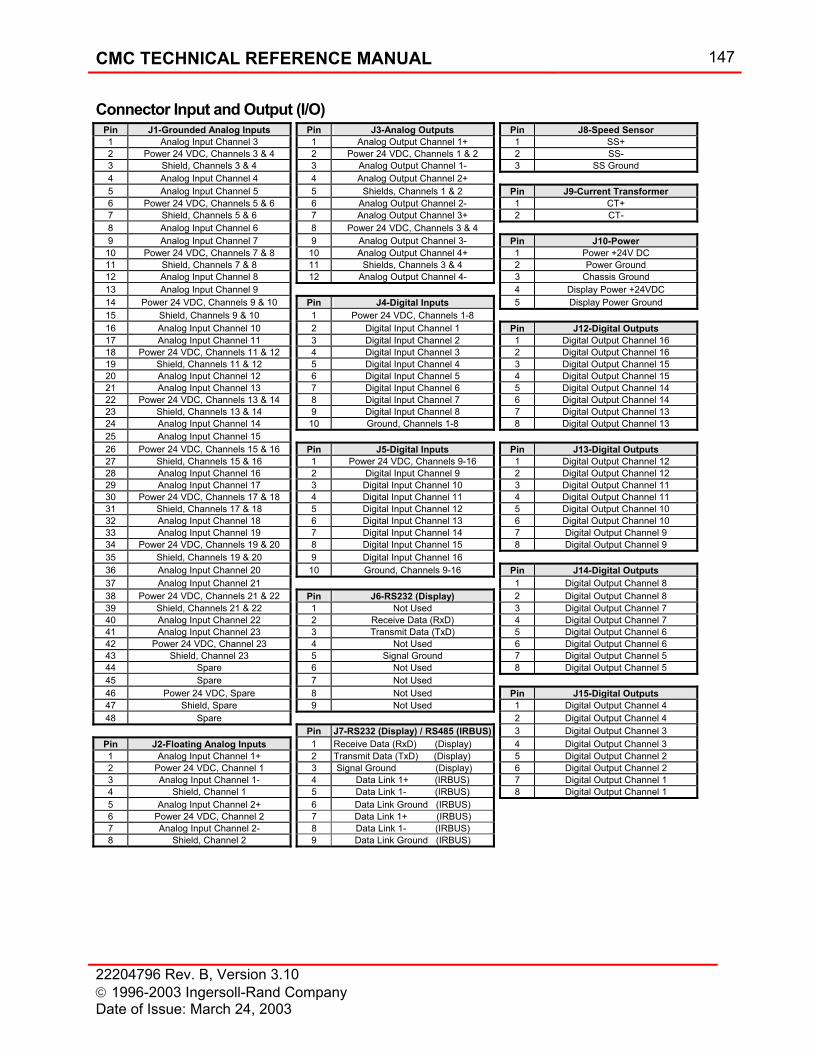
CMC TECHNICAL REFERENCE MANUAL 147
22204796 Rev. B, Version 3.10 1996-2003 Ingersoll-Rand Company Date of Issue: March 24, 2003
Connector Input and Output (I/O) Pin J1-Grounded Analog Inputs Pin J3-Analog Outputs Pin J8-Speed Sensor 1 Analog Input Channel 3 1 Analog Output Channel 1+ 1 SS+ 2 Power 24 VDC, Channels 3 & 4 2 Power 24 VDC, Channels 1 & 2 2 SS- 3 Shield, Channels 3 & 4 3 Analog Output Channel 1- 3 SS Ground 4 Analog Input Channel 4 4 Analog Output Channel 2+ 5 Analog Input Channel 5 5 Shields, Channels 1 & 2 Pin J9-Current Transformer 6 Power 24 VDC, Channels 5 & 6 6 Analog Output Channel 2- 1 CT+ 7 Shield, Channels 5 & 6 7 Analog Output Channel 3+ 2 CT- 8 Analog Input Channel 6 8 Power 24 VDC, Channels 3 & 4 9 Analog Input Channel 7 9 Analog Output Channel 3- Pin J10-Power 10 Power 24 VDC, Channels 7 & 8 10 Analog Output Channel 4+ 1 Power +24V DC 11 Shield, Channels 7 & 8 11 Shields, Channels 3 & 4 2 Power Ground 12 Analog Input Channel 8 12 Analog Output Channel 4- 3 Chassis Ground 13 Analog Input Channel 9 4 Display Power +24VDC 14 Power 24 VDC, Channels 9 & 10 Pin J4-Digital Inputs 5 Display Power Ground 15 Shield, Channels 9 & 10 1 Power 24 VDC, Channels 1-8 16 Analog Input Channel 10 2 Digital Input Channel 1 Pin J12-Digital Outputs 17 Analog Input Channel 11 3 Digital Input Channel 2 1 Digital Output Channel 16 18 Power 24 VDC, Channels 11 & 12 4 Digital Input Channel 3 2 Digital Output Channel 16 19 Shield, Channels 11 & 12 5 Digital Input Channel 4 3 Digital Output Channel 15 20 Analog Input Channel 12 6 Digital Input Channel 5 4 Digital Output Channel 15 21 Analog Input Channel 13 7 Digital Input Channel 6 5 Digital Output Channel 14 22 Power 24 VDC, Channels 13 & 14 8 Digital Input Channel 7 6 Digital Output Channel 14 23 Shield, Channels 13 & 14 9 Digital Input Channel 8 7 Digital Output Channel 13 24 Analog Input Channel 14 10 Ground, Channels 1-8 8 Digital Output Channel 13 25 Analog Input Channel 15 26 Power 24 VDC, Channels 15 & 16 Pin J5-Digital Inputs Pin J13-Digital Outputs 27 Shield, Channels 15 & 16 1 Power 24 VDC, Channels 9-16 1 Digital Output Channel 12 28 Analog Input Channel 16 2 Digital Input Channel 9 2 Digital Output Channel 12 29 Analog Input Channel 17 3 Digital Input Channel 10 3 Digital Output Channel 11 30 Power 24 VDC, Channels 17 & 18 4 Digital Input Channel 11 4 Digital Output Channel 11 31 Shield, Channels 17 & 18 5 Digital Input Channel 12 5 Digital Output Channel 10 32 Analog Input Channel 18 6 Digital Input Channel 13 6 Digital Output Channel 10 33 Analog Input Channel 19 7 Digital Input Channel 14 7 Digital Output Channel 9 34 Power 24 VDC, Channels 19 & 20 8 Digital Input Channel 15 8 Digital Output Channel 9 35 Shield, Channels 19 & 20 9 Digital Input Channel 16 36 Analog Input Channel 20 10 Ground, Channels 9-16 Pin J14-Digital Outputs 37 Analog Input Channel 21 1 Digital Output Channel 8 38 Power 24 VDC, Channels 21 & 22 Pin J6-RS232 (Display) 2 Digital Output Channel 8 39 Shield, Channels 21 & 22 1 Not Used 3 Digital Output Channel 7 40 Analog Input Channel 22 2 Receive Data (RxD) 4 Digital Output Channel 7 41 Analog Input Channel 23 3 Transmit Data (TxD) 5 Digital Output Channel 6 42 Power 24 VDC, Channel 23 4 Not Used 6 Digital Output Channel 6 43 Shield, Channel 23 5 Signal Ground 7 Digital Output Channel 5 44 Spare 6 Not Used 8 Digital Output Channel 5 45 Spare 7 Not Used 46 Power 24 VDC, Spare 8 Not Used Pin J15-Digital Outputs 47 Shield, Spare 9 Not Used 1 Digital Output Channel 4 48 Spare 2 Digital Output Channel 4 Pin J7-RS232 (Display) / RS485 (IRBUS) 3 Digital Output Channel 3
Pin J2-Floating Analog Inputs 1 Receive Data (RxD) (Display) 4 Digital Output Channel 3 1 Analog Input Channel 1+ 2 Transmit Data (TxD) (Display) 5 Digital Output Channel 2 2 Power 24 VDC, Channel 1 3 Signal Ground (Display) 6 Digital Output Channel 2 3 Analog Input Channel 1- 4 Data Link 1+ (IRBUS) 7 Digital Output Channel 1 4 Shield, Channel 1 5 Data Link 1- (IRBUS) 8 Digital Output Channel 1 5 Analog Input Channel 2+ 6 Data Link Ground (IRBUS) 6 Power 24 VDC, Channel 2 7 Data Link 1+ (IRBUS) 7 Analog Input Channel 2- 8 Data Link 1- (IRBUS) 8 Shield, Channel 2 9 Data Link Ground (IRBUS)
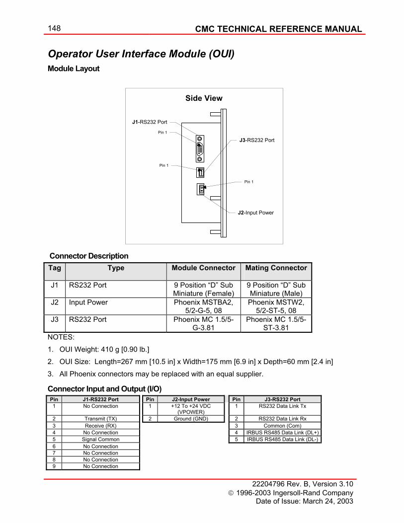
148 CMC TECHNICAL REFERENCE MANUAL
22204796 Rev. B, Version 3.10 1996-2003 Ingersoll-Rand Company
Date of Issue: March 24, 2003
Operator User Interface Module (OUI) Module Layout
J1-RS232 Port
Pin 1
J2-Input Power
Pin 1
Side View
J3-RS232 Port
Pin 1
Connector Description Tag Type Module Connector Mating Connector
J1 RS232 Port 9 Position “D” Sub
Miniature (Female) 9 Position “D” Sub Miniature (Male)
J2 Input Power Phoenix MSTBA2, 5/2-G-5, 08
Phoenix MSTW2, 5/2-ST-5, 08
J3 RS232 Port Phoenix MC 1.5/5-G-3.81
Phoenix MC 1.5/5-ST-3.81
NOTES: 1. OUI Weight: 410 g [0.90 lb.] 2. OUI Size: Length=267 mm [10.5 in] x Width=175 mm [6.9 in] x Depth=60 mm [2.4 in] 3. All Phoenix connectors may be replaced with an equal supplier.
Connector Input and Output (I/O) Pin J1-RS232 Port Pin J2-Input Power Pin J3-RS232 Port 1 No Connection 1 +12 To +24 VDC
(VPOWER) 1 RS232 Data Link Tx
2 Transmit (TX) 2 Ground (GND) 2 RS232 Data Link Rx 3 Receive (RX) 3 Common (Com) 4 No Connection 4 IRBUS RS485 Data Link (DL+) 5 Signal Common 5 IRBUS RS485 Data Link (DL-) 6 No Connection 7 No Connection 8 No Connection 9 No Connection
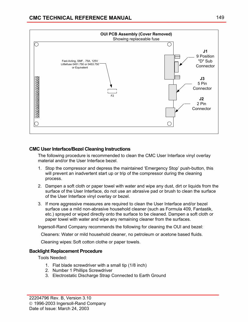
CMC TECHNICAL REFERENCE MANUAL 149
22204796 Rev. B, Version 3.10 1996-2003 Ingersoll-Rand Company Date of Issue: March 24, 2003
J19 Position"D" Sub
Connector
OUI PCB Assembly (Cover Removed)Showing replaceable fuse
J35 Pin
Connector
J22 Pin
Connector
F2
Fast-Acting, SMF, .75A, 125VLittlefuse 0451.750 or 0453.750
or Equivalent
CMC User Interface/Bezel Cleaning Instructions
The following procedure is recommended to clean the CMC User Interface vinyl overlay material and/or the User Interface bezel. 1. Stop the compressor and depress the maintained ‘Emergency Stop’ push-button, this
will prevent an inadvertent start up or trip of the compressor during the cleaning process.
2. Dampen a soft cloth or paper towel with water and wipe any dust, dirt or liquids from the surface of the User Interface, do not use an abrasive pad or brush to clean the surface of the User Interface vinyl overlay or bezel.
3. If more aggressive measures are required to clean the User Interface and/or bezel surface use a mild non-abrasive household cleaner (such as Formula 409, Fantastik, etc.) sprayed or wiped directly onto the surface to be cleaned. Dampen a soft cloth or paper towel with water and wipe any remaining cleaner from the surfaces.
Ingersoll-Rand Company recommends the following for cleaning the OUI and bezel: Cleaners: Water or mild household cleaner, no petroleum or acetone based fluids. Cleaning wipes: Soft cotton clothe or paper towels.
Backlight Replacement Procedure Tools Needed:
1. Flat blade screwdriver with a small tip (1/8 inch) 2. Number 1 Phillips Screwdriver 3. Electrostatic Discharge Strap Connected to Earth Ground
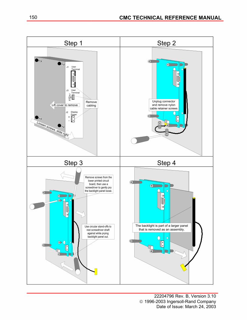
150 CMC TECHNICAL REFERENCE MANUAL
22204796 Rev. B, Version 3.10 1996-2003 Ingersoll-Rand Company
Date of Issue: March 24, 2003
Step 1 Step 2
J2 DisplayPower
J1 UserTerminal
+-Loosen screws, slide right
Lift cover to remove
J3 UserTerminal
Removecabling
TxRx
COMDL+DL-
Unplug connectorand remove nylon
cable retainer screws
Step 3 Step 4
Remove screws from thelower printed circuitboard, then use a
screwdriver to gently prythe backlight panel loose.
Use circular stand-offs torest screwdriver shaftagainst while pryingbacklight panel out.
The backlight is part of a larger panelthat is removed as an assembly.
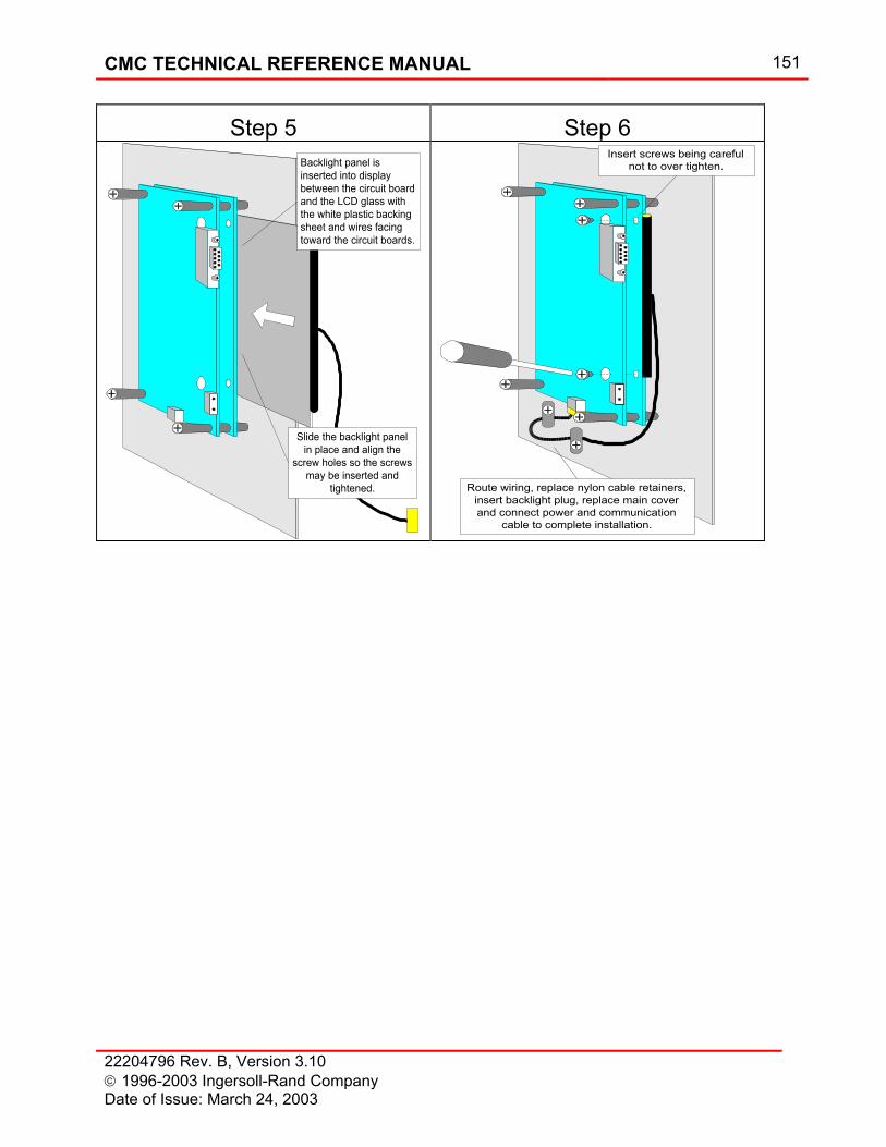
CMC TECHNICAL REFERENCE MANUAL 151
22204796 Rev. B, Version 3.10 1996-2003 Ingersoll-Rand Company Date of Issue: March 24, 2003
Step 5 Step 6
Slide the backlight panelin place and align the
screw holes so the screwsmay be inserted and
tightened.
Backlight panel isinserted into displaybetween the circuit boardand the LCD glass withthe white plastic backingsheet and wires facingtoward the circuit boards.
Insert screws being carefulnot to over tighten.
Route wiring, replace nylon cable retainers,insert backlight plug, replace main coverand connect power and communication
cable to complete installation.
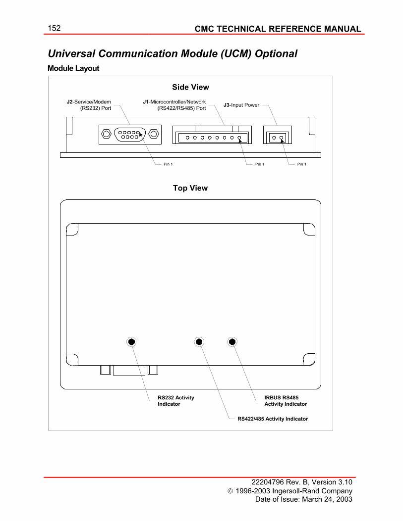
152 CMC TECHNICAL REFERENCE MANUAL
22204796 Rev. B, Version 3.10 1996-2003 Ingersoll-Rand Company
Date of Issue: March 24, 2003
Universal Communication Module (UCM) Optional Module Layout
Side View
Top View
RS232 ActivityIndicator
RS422/485 Activity Indicator
IRBUS RS485Activity Indicator
J1-Microcontroller/Network(RS422/RS485) Port
J2-Service/Modem(RS232) Port J3-Input Power
Pin 1 Pin 1 Pin 1
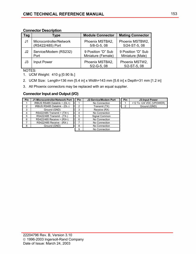
CMC TECHNICAL REFERENCE MANUAL 153
22204796 Rev. B, Version 3.10 1996-2003 Ingersoll-Rand Company Date of Issue: March 24, 2003
Connector Description Tag Type Module Connector Mating Connector J1 Microcontroller/Network
(RS422/485) Port Phoenix MSTBA2,
5/8-G-5, 08 Phoenix MSTBW2,
5/24-ST-5, 08
J2 Service/Modem (RS232) Port
9 Position “D” Sub Miniature (Female)
9 Position “D” Sub Miniature (Male)
J3 Input Power Phoenix MSTBA2, 5/2-G-5, 08
Phoenix MSTW2, 5/2-ST-5, 08
NOTES: 1. UCM Weight: 410 g [0.90 lb.] 2. UCM Size: Length=136 mm [5.4 in] x Width=143 mm [5.6 in] x Depth=31 mm [1.2 in] 3. All Phoenix connectors may be replaced with an equal supplier.
Connector Input and Output (I/O) Pin J1-Microcontroller/Network Port Pin J2-Service/Modem Port Pin J3-Input Power 1 IRBUS RS485 Datalink + (DL+) 1 No Connection 1 +12 To +24 VDC (VPOWER) 2 IRBUS RS485 Datalink - (DL-) 2 Transmit (TX) 2 Ground (GND) 3 Ground (GND) 3 Receive (RX) 4 RS422/485 Transmit + (TX+) 4 No Connection 5 RS422/485 Transmit - (TX-) 5 Signal Common 6 RS422/485 Receive + (RX+) 6 No Connection 7 RS422/485 Receive - (RX-) 7 No Connection 8 Ground (GND) 8 No Connection 9 No Connection
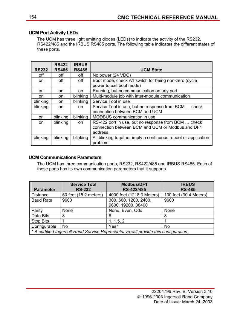
154 CMC TECHNICAL REFERENCE MANUAL
22204796 Rev. B, Version 3.10 1996-2003 Ingersoll-Rand Company
Date of Issue: March 24, 2003
UCM Port Activity LEDs The UCM has three light emitting diodes (LEDs) to indicate the activity of the RS232, RS422/485 and the IRBUS RS485 ports. The following table indicates the different states of these ports.
UCM Communications Parameters The UCM has three communication ports, RS232, RS422/485 and IRBUS RS485. Each of these ports has its own communication parameters that it supports.
RS232
RS422 RS485
IRBUS RS485
UCM State
off off off No power (24 VDC) on off off Boot mode, check A1 switch for being non-zero (cycle
power to exit boot mode) on on on Running, but no communication on any port on on blinking Multi-module job with inter-module communication
blinking on blinking Service Tool in use blinking on on Service Tool in use, but no response from BCM … check
connection between BCM and UCM on blinking blinking MODBUS communication in use on blinking on RS-422 port in use, but no response from BCM … check
connection between BCM and UCM or Modbus and DF1 address
blinking blinking blinking All blinking together imply a continuous reboot or application problem
Parameter
Service Tool RS-232
Modbus/DF1 RS-422/485
IRBUS RS-485
Distance 50 feet (15.2 meters) 4000 feet (1218.3 Meters) 100 feet (30.4 Meters) Baud Rate 9600 300, 600, 1200, 2400,
9600, 19200, 38400 9600
Parity None None, Even, Odd None Data Bits 8 8 8 Stop Bits 1 1, 1.5, 2 1 Configurable No Yes* No * A certified Ingersoll-Rand Service Representative will provide this configuration.
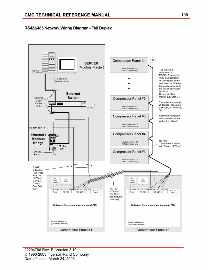
CMC TECHNICAL REFERENCE MANUAL 155
22204796 Rev. B, Version 3.10 1996-2003 Ingersoll-Rand Company Date of Issue: March 24, 2003
RS422/485 Network Wiring Diagram - Full Duplex
Tx+ Tx- Rx+ Rx- GndRS-232
DB-9
DL+ DL- GndRS-422/485RS-485
24+Power
Gnd
ToBCM
ToPowerSupply
Compressor Panel #1
Tx+ Tx- Rx+ Rx- GndRS-232
DB-9
DL+ DL- GndRS-422/485RS-485
24+Power
Universal Communication Module (UCM)
Gnd
ToBCM
ToPowerSupply
Compressor Panel #2
SERVER(Modbus Master)
Compressor Panel #3
Compressor Panel #4
Compressor Panel #5
Compressor Panel #6
Compressor Panel #n
The maximumdistance of aMODBUS Network is4000 electrical feet;i.e., the length of thewire from the EthernetBridge (Location A) tothe last compressor'sUniversalCommunicationModule (Location B).
The maximum numberof devices (nodes) ona MODBUS Network is30.
A terminating resistoris not required at theend of the network.
B
Modbus Address - 01(Set through software)
Modbus Address - 03IRBUS Address - any
Modbus Address - 04IRBUS Address - any
Modbus Address - 05IRBUS Address - any
Modbus Address - 06IRBUS Address - any
Modbus Address - nnIRBUS Address - any
RS-4222 Twisted Pair Wireswith Ground (5 Wires)
RS-4222 TwistedPair Wireswith Ground(5 Wires)
RS-4222 TwistedPair WiresPlus Gnd.(5 Wires)ConnectGroundOne EndOnly
Modbus Address - 02(Set through software)
120 VAC
Com3
+-
Rx- Rx+ Tx+ Tx-
24VDCFused
EthernetSwitch
Ethernet /ModbusBridge
EthernetCable
Cat5 orBetter
To Server'sNetwork Card
120 VAC
174 CEV300
Universal Communication Module (UCM)
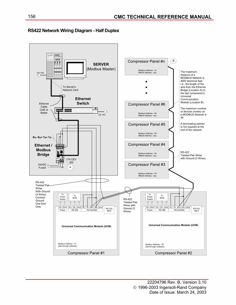
156 CMC TECHNICAL REFERENCE MANUAL
22204796 Rev. B, Version 3.10 1996-2003 Ingersoll-Rand Company
Date of Issue: March 24, 2003
RS422 Network Wiring Diagram - Half Duplex
Tx+ Tx- Rx+ Rx- GndRS-232
DB-9
DL+ DL- GndRS-422/485RS-485
24+Power
Gnd
ToBCM
ToPowerSupply
Compressor Panel #1
Tx+ Tx- Rx+ Rx- GndRS-232
DB-9
DL+ DL- GndRS-422/485RS-485
24+Power
Universal Communication Module (UCM)
Gnd
ToBCM
ToPowerSupply
Compressor Panel #2
SERVER(Modbus Master)
Compressor Panel #3
Compressor Panel #4
Compressor Panel #5
Compressor Panel #6
Compressor Panel #n
The maximumdistance of aMODBUS Network is4000 electrical feet;i.e., the length of thewire from the EthernetBridge (Location A) tothe last compressor'sUniversalCommunicationModule (Location B).
The maximum numberof devices (nodes) ona MODBUS Network is30.
A terminating resistoris not required at theend of the network.
B
Modbus Address - 01(Set through software)
Modbus Address - 03IRBUS Address - any
Modbus Address - 04IRBUS Address - any
Modbus Address - 05IRBUS Address - any
Modbus Address - 06IRBUS Address - any
Modbus Address - nnIRBUS Address - any
RS-422Twisted Pair Wireswith Ground (3 Wires)
RS-422Twisted PairWires withGround (3Wires)
RS-422Twisted PairWiresWith Ground(3 Wires)ConnectGroundOne EndOnly
Modbus Address - 02(Set through software)
120 VAC
Com3
+-
Rx- Rx+ Tx+ Tx-
24VDCFused
EthernetSwitch
Ethernet /ModbusBridge
EthernetCable
Cat5 orBetter
To Server'sNetwork Card
120 VAC
174 CEV300
Universal Communication Module (UCM)
A
CMC TECHNICAL REFERENCE MANUAL 157
22204796 Rev. B, Version 3.10 1996-2003 Ingersoll-Rand Company Date of Issue: March 24, 2003
Terminating Resistor – Modbus Network The RS422/485 circuitry built into each UCM supports Alternate-Fail-safe AC Termination. This termination circuitry enhances the UCM's ability to operation in harsher (electrically noisier) environments. Since this circuitry is built into the product, no external terminating resistor is required. For a thorough discussion of the various termination techniques, please refer to "A Comparison of Differential Termination Techniques", National Semiconductor Application Note 903 (AN-903), August 1993. This application note can be obtained from the Internet at "www.national.com".
Terminating Resistor – IRBUS Network Due to the data rate the RS485 IRBUS is provided with termination resistors mounted inside the panel. The value of each resistor is 470 ohms. The purpose of the termination is to prevent reflections. Reflections occur when a signal encounters different impedance and is reflected back towards the source. This can corrupt the intended data transmission. Where IRBUS is networked with other panels two termination resistors are required, one at each end of the network.
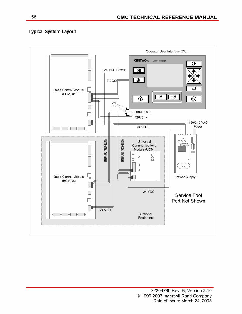
158 CMC TECHNICAL REFERENCE MANUAL
22204796 Rev. B, Version 3.10 1996-2003 Ingersoll-Rand Company
Date of Issue: March 24, 2003
Typical System Layout
CENTAC Microcontroller
24 VDC
24 VDC Power
IRBU
S (R
S485
)
120/240 VACPower
Base Control Module(BCM) #2
Base Control Module(BCM) #1
UniversalCommunicationsModule (UCM)
Power Supply
Operator User Interface (OUI)
24 VDC
24 VDC
IRBU
S (R
S485
)
OptionalEquipment
IRBUS INIRBUS OUT
470ohm
RS232
Service ToolPort Not Shown
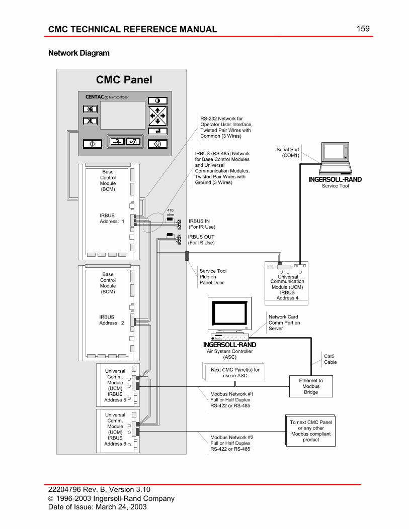
CMC TECHNICAL REFERENCE MANUAL 159
22204796 Rev. B, Version 3.10 1996-2003 Ingersoll-Rand Company Date of Issue: March 24, 2003
Network Diagram
UniversalCommunicationModule (UCM)
IRBUS (RS-485) Networkfor Base Control Modulesand UniversalCommunication Modules,Twisted Pair Wires withGround (3 Wires)
To next CMC Panelor any other
Modbus compliantproduct
INGERSOLL-RANDService Tool
Ethernet toModbusBridge
UniversalComm.Module(UCM)IRBUS
Address 5
IRBUSAddress: 2
BaseControlModule(BCM)
IRBUSAddress: 1
CENTAC Microcontroller
CMC Panel
Serial Port(COM1)
Service ToolPlug onPanel Door
Cat5Cable
Network CardComm Port onServer
Modbus Network #1Full or Half DuplexRS-422 or RS-485
INGERSOLL-RANDAir System Controller
(ASC)
Modbus Network #2Full or Half DuplexRS-422 or RS-485
BaseControlModule(BCM)
Next CMC Panel(s) foruse in ASC
IRBUSAddress 4
UniversalComm.Module(UCM)IRBUS
Address 6
470ohm
IRBUS IN(For IR Use)
IRBUS OUT(For IR Use)
RS-232 Network forOperator User Interface,Twisted Pair Wires withCommon (3 Wires)
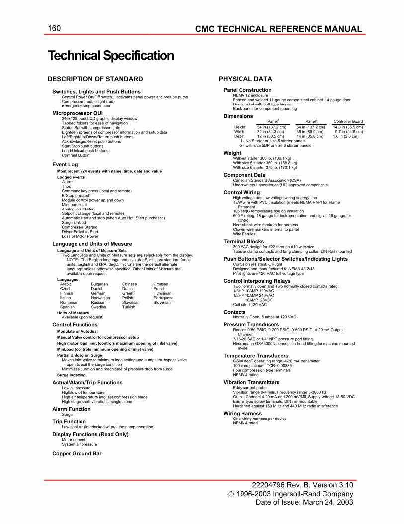
160 CMC TECHNICAL REFERENCE MANUAL
22204796 Rev. B, Version 3.10 1996-2003 Ingersoll-Rand Company
Date of Issue: March 24, 2003
Technical SpecificationDESCRIPTION OF STANDARD
Switches, Lights and Push Buttons Control Power On/Off switch... activates panel power and prelube pump Compressor trouble light (red) Emergency stop pushbutton
Microprocessor OUI 240x128 pixel LCD graphic display window Tabbed folders for ease of navigation Status Bar with compressor state Eighteen screens of compressor information and setup data Left/Right/Up/Down/Return push buttons Acknowledge/Reset push buttons Start/Stop push buttons Load/Unload push buttons Contrast Button
Event Log Most recent 224 events with name, time, date and value Logged events
Alarms Trips Command key press (local and remote) E-Stop pressed Module control power up and down MinLoad reset Analog input failed Setpoint change (local and remote) Automatic start and stop (when Auto Hot Start purchased) Surge Unload Compressor Started Driver Failed to Start Loss of Motor Power
Language and Units of Measure Language and Units of Measure Sets
Two Language and Units of Measure sets are select-able from the display. NOTE: The English language and psia, degF, mils are standard for all units. English and kPA, degC, microns are the default alternate language unless otherwise specified. Other Units of Measure are available upon request.
Languages Arabic Bulgarian Chinese Croatian Czech Danish Dutch French Finnish German Greek Hungarian Italian Norwegian Polish Portuguese Romanian Russian Slovakian Slovenian Spanish Swedish Turkish
Units of Measure Available upon request.
Control Functions Modulate or Autodual Manual Valve control for compressor setup High motor load limit (controls maximum opening of inlet valve) MinLoad (controls minimum opening of inlet valve) Partial Unload on Surge
Moves inlet valve to minimum load setting and bumps the bypass valve open to exit the surge condition
Minimizes duration and magnitude of pressure drop from surge Surge Indexing
Actual/Alarm/Trip Functions Low oil pressure High/low oil temperature High air temperature into last compression stage High stage shaft vibrations, single plane
Alarm Function Surge
Trip Function Low seal air (interlocked w/ prelube pump operation)
Display Functions (Read Only) Motor current System air pressure
Copper Ground Bar
PHYSICAL DATA Panel Construction
NEMA 12 enclosure Formed and welded 11-gauge carbon steel cabinet, 14 gauge door Door gasket with butt type hinges Back panel for component mounting
Dimensions Panel1 Panel2 Controller Board Height 54 in (137.2 cm) 54 in (137.2 cm) 14.0 in (35.5 cm) Width 32 in (81.3 cm) 35 in (88.9 cm) 9.7 in (24.6 cm) Depth 12 in (30.5 cm) 14 in (35.6 cm) 1.0 in (2.5 cm) 1 - No Starter or size 5 starter panels 2 - with size 5DP or size 6 starter panels
Weight Without starter 300 lb. (136.1 kg) With size 5 starter 350 lb. (158.8 kg) With size 6 starter 375 lb. (170.1 kg)
Component Data Canadian Standard Association (CSA) Underwriters Laboratories (UL) approved components
Control Wiring High voltage and low voltage wiring segregation TEW wire with PVC insulation (meets NEMA VM-1 for Flame
Retardant 105 degC temperature rise on insulation 600 V rating, 18 gauge for instrumentation and signal, 16 gauge for
control Heat shrink wire markers for harness Clip-on wire markers internal to panel Wire Ferules
Terminal Blocks 300 VAC design for #22 through #10 wire size Tubular clamp contacts and tang clamping collar, DIN Rail mounted
Push Buttons/Selector Switches/Indicating Lights Corrosion resistant, Oil-tight Designed and manufactured to NEMA 4/12/13 Pilot lights are 120 VAC full voltage type
Control Interposing Relays Two normally open and Two normally closed contacts rated: 1/3HP 10AMP 120VAC 1/2HP 10AMP 240VAC 10AMP 28VDC Coil rated 120 VAC
Contacts Normally Open, 5 amps at 120 VAC
Pressure Transducers Ranges 0-50 PSIG, 0-200 PSIG, 0-500 PSIG, 4-20 mA Output
Channel 7/16-20 SAE or 1/4" NPT pressure port fitting Hirschmann GSA3000N connection head fitting for machine mounted
model
Temperature Transducers 0-500 degF operating range, 4-20 mA transmitter 100 ohm platinum, TCR=0.00385 Four compression type terminals NEMA 4 rating
Vibration Transmitters Eddy current probe Vibration range 0-4 mils, Frequency range 5-3000 Hz Output Channel 4-20 mA and 200 mV/Mil, Supply voltage 18-50 VDC Barrier type screw terminals, DIN rail mountable Hardened against 150 MHz and 440 MHz radio interference
Wiring Harness One wiring harness per device NEMA 4 rated

CMC TECHNICAL REFERENCE MANUAL 161
22204796 Rev. B, Version 3.10 1996-2003 Ingersoll-Rand Company Date of Issue: March 24, 2003
OPTIONS Analog Inputs (Monitor, Alarm and Trip)
Any Temperature Any Pressure Any Vibration Any 4-20 mA signal
Digital (Discrete) Inputs (Monitor and Alarm or Trip) Low water flow Dirty inlet filter (switch supplied loose) Dirty oil filter Low oil level High condensate level (common for all traps) High motor temperature Any Discrete Input
Panel Enclosures Cooing Fan with Filter
110/115 VAC, 50/60 Hz, 0.24 Amps, 20 Watts Air flow with filter 36 CFM (61 M3/Hr)
NEMA 4 Enclosure Space Heater, Vortex Tube Cooler
NEMA 4X Enclosure Space Heater, Vortex Tube Cooler Stainless steel or epoxy coated carbon steel
Space Heater 120 VAC, 120 Watts, finned strip heater Bimetallic baseboard type thermostat set at 45 degF (7 degC)
Vortex Tube Cooler 25 SCFM (42 NM3/Hr) at 100 PSIG (7 BarG) of compressed air 1500 BTU/Hr (378 kCal/Hr), Thermostat set at 90 degF (32 degC) Solenoid operated valve, Air Filter
Type Z Purge Select-able quick and normal flow rates with meters Differential pressure switch set at 0.2 inches (5 mm) of water Loss of purge indication, Relief valve, Warning label
Fused Control Power Disconnect Rotary handle through door, 30 amp fuse
Ground Fault Protector for UL Panels 120 Vac circuits protected against ground fault currents.
Control Electrical Package (Standard on CV) Prelube Pump Motor Starter
Two horsepower and less Available voltages 380, 460, 575 VAC Maximum voltage rating 600 VAC, 10 Amp rating, 120 VAC coils IEC Style
Heater Contactor IEC Style, Adjustable ambient compensated overloads Available voltages 380, 460, 575 VAC Maximum voltage rating 600 VAC, 10 Amp rating, 120 VAC coils
Control Power Transformer Machine tool type, 230, 460, 575 VAC to 120/95 VAC 500 VA or optional 1000 and 1500 VA, 50 or 60 Hz
Transient Voltage Surge Suppressor UL 1449 Listed Tested to ANSI / IEEE C62.41 category A and B environments.
Stage Data Package (Standard on CV) Interstage Air Pressure and Temperature each stage
Alarm Horn 80-95 dBA, 2900 Hz
Running Unloaded Shutdown Timer Timing range and mode select-able through CMC
Water Solenoid Post Run Timer Timing range and mode select-able through CMC
Inlet Valve Tight Closure Keeps inlet valve closed until motor reaches full speed 0-30 second timer range settable by IR Service Tech
Diesel Engine Driven Compressor Control Steam and Gas Turbine Driven Compressor Control Main Motor Starter (Wye-Delta)
NEMA Size 5 or 6 Open transition type, Ambient compensated overloads Available voltages 380, 460, 575 VAC, 120 VAC coils
Power Regulating Transformer 120 VAC, 60 Hz, 250 VA -65% Input Channel line variation, Output Channel +5-10% NEMA
Specification ±15% Input Channel line variation, Output Channel ±3%
Automatic Starting Automatic Hot Start
REMOTE FUNCTIONS DISABLED/ENABLED Selector Switch Solenoid Valves for Intercoolers CMC settable start up pressure setpoint Post Run Water Flow Timer
Automatic Cold Start CONTROL POWER LOCAL/OFF/ COLD Selector Switch Strobe Light Solenoid Valves for Intercoolers and Instrument Air Line CMC settable start up pressure setpoint Post Run Water Flow Timer Start Timer Lube Oil Alarm Bypass Timer
COMMUNICATIONS OPTIONS Communications Card(s)
Up to three cards per module RS-422/485 Local/Network Selector Switch
Direct CMC Communication with RS422/RS-485 Requires programming application by customer Utilizes standard MODBUS protocol or Allen-Bradley DF1 protocol for
PLC2, PLC5 and SLC500 devices
Hard Wired Communication REMOTE FUNCTIONS DISABLED/ENABLED Selector Switch Contacts for Remote Start/Stop, Load/Unload, Acknowledge/Reset Trouble Indication Contacts (Alarm and Trip, Alarm Only or Trip Only) Remote 4-20 for Pressure Setpoint Running Unloaded Contact
Air System Controller (ASC) Features
Sequencing, load sharing and energy management for eight (8) compressors (more depending on network design and hardware)
A CMC Communication Adapter mounted in each CMC panel Max distance from last compressor to Communication Adapter is 4000
feet (1218 meters) Modbus to Ethernet Bridge Ethernet Switch
ASC Personal Computer (running Server Software) Pentium IV processor (Minimum 1.4GHz microprocessor) 256 MB RAM (512 Recommended) 144 MB 3.5 inch diskette drive Network Interface card Recordabel/Rewriteable CD ROM Drive 144 MB 3.5 inch diskette drive Minimum 40.0 GB hard drive
CUSTOMER RESPONSIBILITIES Three phase power Clean, dry control air 80-150 PSIG (5.62-10.55 kg/cm2)
Control air tubing from control air header, 1/4 in (0.635 cm) FNPT connection
Mount and wire external switches and field wired devices Tuning control parameters for system Current transformer – instrument grade
0-5 amp Better than 1% accuracy
CONTROLLER OPERATING ENVIRONMENT Electrical Operation
115 VAC ±5% 24 VDC Instruments except three wire RTDs 32 VA of AC power requirement 50/60 Hz AC supply frequency
Temperatures Operating temperature 32 to 140 degF (0 to 60 degC) Storage temperature -4 to 158 degF (-20 to 70 degC)
Relative Humidity 95% (maximum) non-condensing
DOCUMENTATION Instruction book Electrical schematic Panel Outline drawing (Optional)

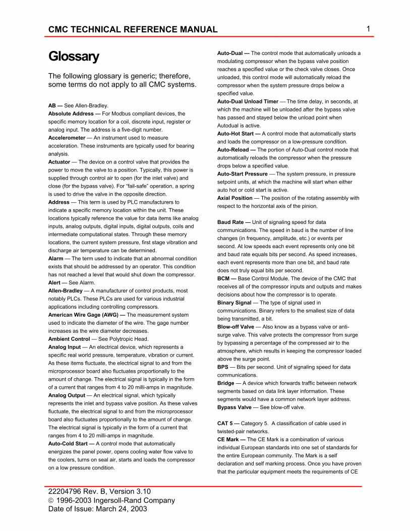
CMC TECHNICAL REFERENCE MANUAL 1
22204796 Rev. B, Version 3.10 1996-2003 Ingersoll-Rand Company Date of Issue: March 24, 2003
Glossary The following glossary is generic; therefore, some terms do not apply to all CMC systems. AB — See Allen-Bradley. Absolute Address — For Modbus compliant devices, the specific memory location for a coil, discrete input, register or analog input. The address is a five-digit number. Accelerometer — An instrument used to measure acceleration. These instruments are typically used for bearing analysis. Actuator — The device on a control valve that provides the power to move the valve to a position. Typically, this power is supplied through control air to open (for the inlet valve) and close (for the bypass valve). For “fail-safe” operation, a spring is used to drive the valve in the opposite direction. Address — This term is used by PLC manufacturers to indicate a specific memory location within the unit. These locations typically reference the value for data items like analog inputs, analog outputs, digital inputs, digital outputs, coils and intermediate computational states. Through these memory locations, the current system pressure, first stage vibration and discharge air temperature can be determined. Alarm — The term used to indicate that an abnormal condition exists that should be addressed by an operator. This condition has not reached a level that would shut down the compressor. Alert — See Alarm. Allen-Bradley — A manufacturer of control products, most notably PLCs. These PLCs are used for various industrial applications including controlling compressors. American Wire Gage (AWG) — The measurement system used to indicate the diameter of the wire. The gage number increases as the wire diameter decreases. Ambient Control — See Polytropic Head. Analog Input — An electrical device, which represents a specific real world pressure, temperature, vibration or current. As these items fluctuate, the electrical signal to and from the microprocessor board also fluctuates proportionally to the amount of change. The electrical signal is typically in the form of a current that ranges from 4 to 20 milli-amps in magnitude. Analog Output — An electrical signal, which typically represents the inlet and bypass valve position. As these valves fluctuate, the electrical signal to and from the microprocessor board also fluctuates proportionally to the amount of change. The electrical signal is typically in the form of a current that ranges from 4 to 20 milli-amps in magnitude. Auto-Cold Start — A control mode that automatically energizes the panel power, opens cooling water flow valve to the coolers, turns on seal air, starts and loads the compressor on a low pressure condition.
Auto-Dual — The control mode that automatically unloads a modulating compressor when the bypass valve position reaches a specified value or the check valve closes. Once unloaded, this control mode will automatically reload the compressor when the system pressure drops below a specified value. Auto-Dual Unload Timer The time delay, in seconds, at which the machine will be unloaded after the bypass valve has passed and stayed below the unload point when Autodual is active. Auto-Hot Start — A control mode that automatically starts and loads the compressor on a low-pressure condition. Auto-Reload — The portion of Auto-Dual control mode that automatically reloads the compressor when the pressure drops below a specified value. Auto-Start Pressure The system pressure, in pressure setpoint units, at which the machine will start when either auto hot or cold start is active. Axial Position — The position of the rotating assembly with respect to the horizontal axis of the pinion. Baud Rate — Unit of signaling speed for data communications. The speed in baud is the number of line changes (in frequency, amplitude, etc.) or events per second. At low speeds each event represents only one bit and baud rate equals bits per second. As speed increases, each event represents more than one bit, and baud rate does not truly equal bits per second. BCM — Base Control Module. The device of the CMC that receives all of the compressor inputs and outputs and makes decisions about how the compressor is to operate. Binary Signal — The type of signal used in communications. Binary refers to the smallest size of data being transmitted, a bit. Blow-off Valve — Also know as a bypass valve or anti-surge valve. This valve protects the compressor from surge by bypassing a percentage of the compressed air to the atmosphere, which results in keeping the compressor loaded above the surge point. BPS — Bits per second. Unit of signaling speed for data communications. Bridge — A device which forwards traffic between network segments based on data link layer information. These segments would have a common network layer address. Bypass Valve — See blow-off valve. CAT 5 — Category 5. A classification of cable used in twisted-pair networks. CE Mark — The CE Mark is a combination of various individual European standards into one set of standards for the entire European community. The Mark is a self declaration and self marking process. Once you have proven that the particular equipment meets the requirements of CE
2 CMC TECHNICAL REFERENCE MANUAL
22204796 Rev. B, Version 3.10 1996-2003 Ingersoll-Rand Company
Date of Issue: March 24, 2003
Mark and have the data to back it up, you may mark the product with the CE Mark. Citect — One of many SCADA software packages that can be used for air system integration. Choke — Also know as stonewall. This is the maximum flow that can be compressed by a given machine’s hardware configuration. Circuit Breaker — An automatic switch that stops the flow of electric current in a suddenly overloaded or abnormally stressed electric circuit. CMC — Centac MicroController. CMC System — Any combination of CMC control components which when combined create a control system. The typical CMC system consists of a Base Control Module (BCM), Operator User Interface (OUI), and Power Supply (PS). A common variation on the typical system is the addition of a Universal Communications Module (UCM). Coast Timer — The time interval, in seconds, between a compressor stop or trip and the motor coming to a complete stop. The timer is used to inhibit restarting. Compressor Load, Load — The power consumption of the compressor. It is typically indicated in amps, kilowatts, SCFM, etc. COM Port — See Serial Port. Control Transformer — The transformer that is used to reduce the incoming voltage (for the prelube pump motor and oil heater) to approximately 120 volts for controlling the CMC electrical devices (relays, power supply, etc.). Control Valve — The inlet or bypass valve used to control pressure or current. Control Variable, Process Variable — The variable being regulated. When at MinLoad the control variable is load for the inlet valve and System Pressure for the bypass valve. When at MaxLoad the control variable is load and when loaded the control variable is System Pressure. CSA Approval — Canadian Standards Association approval is required for all electrical devices shipped into Canada. This association is similar to UL for the United States and CE for Europe. CT — Current Transformer. CT Input Channel — The current transformer input channel. CT Ratio — Current Transformer Ratio. The current transformer ratio used in displaying the motor current; e.g. 600:5 = 120. Current Transformer — The electrical device used to measure the amps of the main drive motor. For our standard application, we only measure the current from one of the three phases. Daisy Chain — A method of wiring a communication network. This method starts with the “master” and it is wired directly to compressor #1. Compressor #2 is wired to compressor #1, then compressor #3 is wired to compressor #2.
Data Link — A direct serial data communications path between two devices without intermediate switching nodes. Data Highway Plus — A communication protocol used by Allen-Bradley PLC 5 and SLC500 PLCs. DCS — See Distributed Control System. degC — Degrees Celsius, Centigrade. degF — Degrees Fahrenheit. DH+ — See Data Highway Plus. Derivative Mode — Provides a change in the control variable (through the inlet or bypass valve) based on the rate of change of the error (setpoint pressure minus system pressure). Derivative Constant — Also know as the rate time, in units of seconds. Design Point — The pressure and capacity required at maximum ambient conditions. Digital Device — A device, which is either on or off; e.g., the N.C. contact on the seal air switch. Discrete Device — See Digital Device. Discharge Pressure — The gas pressure between the last stage of compression and the check valve. Distributed Control System — A system that attempts to control an entire plant or process with multiple independent local controllers by networking these local controllers to a central computer through digital communications. These central computers can be a PC, PLCs or other larger systems. Some manufacturers of these DCS products are Bailey, Honeywell, Allen-Bradley, Siemens, and others. Drain Wire — An insulated wire in contact with a shield throughout its length, and used for terminating the shield. Dry Contacts — A set of contacts that require a power source supplied by others (customer). This is the normal type of contacts that we provide. Electro-pneumatic — A term used to indicate a combination of electronics and pneumatics. In the past, we provided electro-pneumatic panels as standard equipment. With the advent of digital computers, most all control panels are electronic. ERAM — Erasable Random Access Memory. Event — The control transfer or “rule(s)” as used in State Logic to transfer from one state to another. FactoryLink — One of many SCADA software packages that can be used for air system integration. FLA — Motor Full Load Amps. The motor amperage at full load, this value is found on the motor nameplate. Flexible Conduit — Small diameter hose, made of plastic coated aluminum, which is used to enclose wire from the control panel to machine mounted instruments. Fused Disconnect — As a safety precaution, this option removes power from the panel before the door is opened. By turning the rotary door handle, the panel power is terminated. The disconnect would have to be mounted
CMC TECHNICAL REFERENCE MANUAL 3
22204796 Rev. B, Version 3.10 1996-2003 Ingersoll-Rand Company Date of Issue: March 24, 2003
external to the panel enclosure. The short circuit capacity, maximum ground fault, motor full load amps, motor locked rotor amps and motor voltage must be known to size the disconnect properly. Ground — A connection to earth or to some extended conducting body that serves instead of the earth. Ground Loop — An unwanted, continuous ground current flowing back and forth between two devices that are at different ground potentials. Grounded System — An electrical system in which at least one point (usually a wire) is intentionally grounded. Head — See Polytropic Head. High Load Limit — See HLL HLL — High Load Limit. The load that the controller maintains when at MaxLoad. I/O — See Input/Output. IBV — Inlet Butterfly Valve. See Inlet Valve. IEC — International ElectroTechnical Commission is the governing body of Europe for electrical equipment and codes. IGV — Inlet Guide Vanes. See Inlet Valve. Inlet Unload Position — The position of the inlet valve when in the unloaded state. Inlet Valve — The device used on the inlet pipe to the compressor that restricts the amount of airflow to the compressor. This valve can be a butterfly valve or a valve with inlet guide vanes. Input/Output —The hardware interface between the compressor and the control system. This term generically applies to the entire interface circuit including sensor, wiring, and junction points. Instrument Air — The air supply to the panel that is directed to the power air system for the inlet and bypass valves and the compressor seals. Integral Mode — Provides a change in the control variable (through the inlet or bypass valve) based on the time history of the error (setpoint pressure minus system pressure). Integral Time Constant—This value is expressed in repeats per second and represents the number of times per second the integral mode acts. Intellution — One of many SCADA software packages that can be used for air system integration. Interface — The hardware or software device used to communicate between products. Interlock — An electrical function that prevents the compressor from starting in the event that the function has not been satisfied. For example, the seal air interlock prevents the compressor from starting until the seal air pressure is adequate. IRBUS — The proprietary communication protocol used to communicate to and from one or many Base Control Modules
(BCM), Universal Communication Modules (UCM) and Operator User Interfaces (OUI). Loopback — A diagnostic test in which a transmitted communication signal is returned to the sending device after passing through all or part of the communication network. This test compares the transmitted signal to the received signal. The test passes if the signals are identical. MA, mA — Milliampere Maintained Contact — A contact closure that remains closed. MaxLoad — The message displayed on the OUI Status Bar when the machine is running at MaxLoad. MinLoad — The message displayed on the OUI Status Bar when the machine is running at MinLoad. MMI — Man Machine Interface. The term used to indicate the device or method used for a human to interface with a machine. Typically these interfaces are LCD displays or computer screens. For the CMC, the MMI is the Operator User Interface (OUI). Modbus — A sixteen-bit communication protocol originally developed for Modicon PLCs. This protocol has become a defacto standard for industrial equipment. Modicon — A PLC brand name manufactured by Schneider Automation. Modulate — The control mode that opens and closes (modulates) the inlet or bypass valve to maintain a constant discharge pressure. This is the primary control mode for centrifugal compressors. Momentary Contact — A contact closure that closes and then opens. N.C. — Normally Closed. Used to indicate the state of a contact when no power is applied. N.O. — Normally Open. Used to indicate the state of a contact when no power is applied. Natural Curve — The set of pressure and capacity points that define the operating characteristic of the centrifugal compressor. Natural Surge — The point on the natural curve that is represented by the maximum pressure and minimum capacity. NEMA — National Electrical Manufacturers Association. Network — A series of points, nodes or devices connected by some type of communication medium. On-Line/Off-Line — Control mode that allows the system discharge pressure to fluctuate between two pressure setpoints. The compressor will load when the actual pressure is below the lower setpoint pressure and will unload when it reaches the higher setpoint pressure. This type of control mode is normally used on reciprocating and rotary compressors.
4 CMC TECHNICAL REFERENCE MANUAL
22204796 Rev. B, Version 3.10 1996-2003 Ingersoll-Rand Company
Date of Issue: March 24, 2003
OUI — Operator User Interface. The device on the CMC that gathers user inputs and provides compressor operating status. Parity — The addition of non-information bits to make up a data transmission block that ensures the total number of 1s is either even (even parity) or odd (odd parity). This is used to detect errors in communication transmission. Partial Unload — See Surge Absorber. Password — The four digit parameter used to determine when the user can modify setpoints. The range of this password is 0000 to 9999. PID — Proportional, Integral, Derivative. The parameters used to adjust the behavior of PID control loops. PLC — Programmable Logic Controller. This hardware device is configurable such that many types of analog and digital inputs and outputs can be utilized to control various industrial products. PLC 5 — Type of Allen-Bradley PLC used for large applications. Pneumatic — Run by or using compressed air. Polytropic Head — The energy in foot-pounds to transfer one pound of given gas from one pressure level to another. (ft-lb/lb) Positioner — The device on a control valve that instructs the actuator how much (to what position) to move the valve. PROM — Programmable Read Only Memory. Proportional Mode — Provides a change in the control variable (through the inlet or bypass valve) proportional to the error (setpoint pressure minus system pressure). Proportional Band Constant — The percent change in system air pressure that causes a percent change in the valve position. This value is dimensionless. Protocol — A formal set of conventions governing the formatting and relative timing of message exchange between two communication systems. RAM — Random Access Memory. Relative Address — For Modbus compliant devices, the four-digit address within the range of 0-9999. The relative address can be determined from the absolute address by deleting the type (the ten-thousandth place) and subtracting one. Reload Percent — The reload pressure, in percent of user pressure set point, at which the machine will load when Autodual is active. Rigid Conduit — Small diameter pipe, made of carbon steel with welded connections, which is used to enclose wire from the control panel to machine mounted instruments. This conduit is typically used in hazardous area classifications. Rise To Surge — The amount of pressure from the operating pressure to the natural surge pressure. This amount is usually expressed in percent. RS-232 — Electronic Industries Association interface standard between data terminal equipment and data communication equipment, using serial binary data interchange. This is the most common standard used by industry.
RS-232 to RS-422/485 Converter — A hardware device that electrically converts an RS-232 signal into an RS-422 or RS-485 signal. RS-422 — Electronic Industries Association interface standard that specifies electrical characteristics for balanced circuits and extends transmission speed and distances beyond RS-232. This standard is a balanced voltage system with a high level of noise immunity. RS-485 — Electronic Industries Association balanced interface standard similar to RS-422, but uses a tri-state driver for multi-drop applications. RTD — Resistance Temperature Detector. An instrument that measures temperature by detecting the voltage across the RTD material (mostly platinum). The temperature is determined because as the temperature increases the resistance increases. RTU — Remote Terminal Unit. A device typically used for data acquisition to gather data. By using this definition, the Base Control Module is an RTU. SCADA — Supervisor Control and Data Acquisition. The generic classification for software that gathers data for control of industrial products. Sequencer — A hardware or software device that controls the order in which compressors starts, stops, loads and unloads. Some sequencers also control loading and unloading through incremental pressure setpoints among the compressors. For example, in a three-compressor application the setpoints may be 101 psi for compressor #1, 100 psi for compressor #2 and 99 psi for compressor #3. Assuming the pressure transducers were calibrated within one psi of each other and the machines were running unloaded, this configuration would drive compressor #1 to load first when the pressure dropped to 101 psi. Serial Device — A Personal Computer (PC), Programmable Logic Controller (PLC), Distributed Control System (DCS) or any other device that can transmit, receive and interpret an RS422/485 formatted signal. Serial Port — The RS-232 connection on the back of a PC to communicate with other equipment. This connection is typically referred to as COM1. A single PC can have more than one serial port. Service Tool — The software used on the PC to configure, tune, record and log data from the CMC. Service Tool Plug — A port on Panel door to provide access to IRBUS Network. Requires Laptop and external UCM. Setpoint Ramp Rate — The gradual increase of the system pressure set point during a loading operation of the compressor. The ramping of the system pressure set point helps to smooth the transition and prevents a pressure overshoot in the air system upon initial compressor loading. Shielded Wire — Wire that has a sheet, screen or braid of metal, usually copper, aluminum, or other conducting
CMC TECHNICAL REFERENCE MANUAL 5
22204796 Rev. B, Version 3.10 1996-2003 Ingersoll-Rand Company Date of Issue: March 24, 2003
material placed around or between electric circuits or cables or their components, to contain any unwanted radiation, or to keep out any unwanted interference. SLC500 — Type of Allen-Bradley PLC used for relatively small applications and is lower in cost than an equivalent PLC 5. Start Timer — The time interval, in seconds, between pressing the Start button and the compressor is running at full speed. The timer is used to transition wye delta starters, inhibit loading, de-energize the prelube pump, and disable the alternate alarm and trip setpoints. State — A task that is currently being executed in State Logic. Only one state is active at one time. State Logic — State Logic is an alternative to traditional control languages used for machines, systems, and processes. State Transition — The movement from one state to another based on one or more events. Status Bar — The Status Bar provides four distinct types of information (Compressor Operating State, Compressor Status, Compressor Control Location and Page Number). This region is always visible from any folder and page combination. Stonewall — See Choke. Surge Absorber — The reaction of the control system to a surge that pops the bypass valve open by a small percentage to get the compressor out of the surge condition. This feature is initiated by surge detection. Surge Anticipation — The ability of a control system to prevent surge by predicting that a surge is about to happen. Surge Detection — The ability of a control system to indicate that a surge has happened. This feature is important because a persistent surge condition can damage the compressor. Once detected, the control system can respond to the event by taking a corrective action; i.e., by opening the bypass valve. Surge Indexing — A method of automatically increasing the setting of TL upon a surge. Surge Indexing TL — The setpoint at which the inlet valve controls to MinLoad. Surge Line — A series of points that represent natural surge for various inlet pressure conditions. Surge PTX — Surge Pressure Transducer. Surge PTX is mounted between the last compression stage and the check valve. Surge Sensitivity — A setpoint that is used to indicate the magnitude of pressure and current changes that occur during a surge condition. This setpoint determines when the control system detects a surge. Surge Unload — The reaction of the control system to a surge that unloads the compressor to exit the surge condition. This feature is initiated by surge detection. Switch, Ethernet — A device connected to several other devices. Transfers messages across the network. System Pressure — The pressure at the location of the system pressure transducer.
Terminal Block — A device that is used to connect to wires. Typically, these blocks are provided for customer field wiring to the panel and when one wire is to be connected to multiple devices. Terminating Resistor — A resistor placed at the end of a communication network for absorbing or sufficiently attenuating signals incident on it so that they are not reflected back into the transmission line at amplitudes where they would cause distortion of the data signal. Typically, a resistor is placed at each end of the network to help eliminate noise. Thermocouple — A device used to measure temperatures accurately and consists of two dissimilar metals joined so that a voltage is generated between to the contacts of the two metals as the temperature changes. Throttle Limit — See TL. Throttled Surge — The condition created by closing the inlet valve past the surge point to maintain constant pressure. Tight Closure — A term used to describe the inlet valve position when the compressor is not running and starting. The inlet valve ideally is closed tightly when stopped to prevent reverse rotation of the compressor if the check valve fails. Also, to reduce the load on the compressor during starting, the inlet valve can be held closed for a short period of time (less than thirty seconds) after the start button is pushed. This is most typically done on compressors at high altitude, most notably snow making applications. Bearing analysis must be done prior to using this option. TL — Throttle Limit. Establishes the minimum flow through the machine when loaded, it is the maximum point of inlet valve throttling. If system demand is below this throttle point, the compressor must bypass air to maintain pressure setpoint or unload. TL increment value — When Surge Indexing is enabled, the TL increment value is the amount added to the Surge Indexing TL upon a surge. The Surge Indexing TL will stop being incremented when and if the value reaches MaxLoad. Transducer — An electrical device that provides a usable output (4-20 mA, 0-5 vDC, etc.) in response to a measured property (pressure, temperature, etc.). Transformer — An electrical device that transfers energy from one circuit to another by electromagnetic induction. Transient Voltage Surge Suppressor — An electrical device that prevents temporary over-voltages of short duration (typically associated with lightning strikes and ground faults on an ungrounded system) from damaging other electrical equipment. Transmitter — An electrical device that sends the digital representation of a real measured value (e.g., pressure, temperature), to the BCM in the control panel for analysis and display. Turndown — The amount of capacity that can be decreased from full load (maximum load) at a constant pressure before

6 CMC TECHNICAL REFERENCE MANUAL
22204796 Rev. B, Version 3.10 1996-2003 Ingersoll-Rand Company
Date of Issue: March 24, 2003
the bypass valve begins to open to avoid surge. This amount is usually expressed as a percent of full load capacity. TVSS — See Transient Voltage Surge Suppressor. Twisted Pair Wire — Paired cables allow balanced signal transmission, which results in signals with low noise. Due to the improved noise immunity of twisted pairs, data speeds are usually higher than those of multi-conductor cables. UCM — Universal Communications Module. The device that allows outside systems to communicate with the CMC. UL — Underwriter’s Laboratory. Ungrounded System — An electrical system, without an intentional connection to ground. Unload — The operating mode that passes a small amount of air through the compressor and bypasses it to the atmosphere. In this mode, the inlet valve is cracked open a small amount and the bypass valve is fully open. This mode is used when starting the compressor before loading, stopping the compressor and during periods of no demand. Unload Point — The bypass valve position, in percent open, at which the Autodual unload timer will start timing to unload the compressor when Autodual is active. User Pressure Set Point — The local control pressure set point. Valve Stroking — The process of calibrating the valves to align the fully open position to 100 percent and the fully closed position to 0 percent of output signal. VDC — Volts Direct Current Voltage Regulator — An electrical device that maintains voltage to a predefined level. Wait Timer — The delay interval, in seconds, between power up and the ready state. Wire Gage — See American Wire Gage. Wonderware — One of many SCADA software packages that can be used for air system integration. Z-Purge — Required when the customer environment is Division 2. A Type Z Purge reduces the classification within an enclosure from Division 2 too non-hazardous. When provided, a NEMA 4 or NEMA 4X enclosure is required. Hand valve selectable quick and slow purges, with flow meters are provided to regulate the amount of gas entering the panel. A differential pressure switch is wired to a light on the front of the panel to indicate if there is a loss of purge gas. A relief valve is installed to prevent over-pressurization and a warning label, text below, is affixed to the front of the panel.