CM Distance Sensors - · PDF fileCM Distance Sensors. Connections and hardware of the sensors...
52
CM Distance Sensors Configuration and API Guide
-
Upload
vuongkhuong -
Category
Documents
-
view
236 -
download
0
Transcript of CM Distance Sensors - · PDF fileCM Distance Sensors. Connections and hardware of the sensors...

CM Distance Sensors
Configuration and API Guide

____________________________________________________________________________________
____________________________________________________________________________________ CM Configuration and API Guide Page 2/52
____________________________________________________________________________________
____________________________________________________________________________________ CM Configuration and API Guide Page 3/52
Contact information
Noptel Oy Address: Teknologiantie 2
FI-90590 Oulu Finland
Tel.: +358 40 181 4351 Fax: +358 8 556 4101 E-mail: [email protected] Technical support: Web site: www.noptel.fi
Downloads:
Documents :
http://www.noptel.fi/eng/nms/index.php?doc=7_downloads/5_manuals&group=MSC
Software:
http://www.noptel.fi/eng/nms/index.php?doc=7_downloads/7_software&group=MSC
Firmware:
http://www.noptel.fi/eng/nms/index.php?doc=7_downloads/ Ask from [email protected]
Document Information :
Document Title: CM Distance Sensors Configuration and API Guide Document Version: 1.5 Released: 07.05.2013 Current printing 7.5.2013 Document ID : N42119BE Document Status: Draft Firmware version CM3: 0.32.x2 (CM3 and CMP3) Firmware version CM5: 0.20.xx (CM5, CMP51 and CMP52)
Copyright Notice:
Specifications, and implementation subject to change without notice due to continuous research and development.
Copyright © 2013 Noptel Oy, Oulu, Finland
____________________________________________________________________________________
____________________________________________________________________________________ CM Configuration and API Guide Page 4/52
1 INTRODUCTION TO THE CM DISTANCE SENSORS ............................................5
1.1 INTRODUCTION .............................................................................................................5
1.2 COMMUNICATION PROTOCOL.........................................................................................5
1.3 COMMANDS IN CONFIGURATION MODE ...........................................................................6
2 OPERATION MODES...............................................................................................9
2.1 LIST OF OPERATION MODES...........................................................................................9
2.2 OUTPUT AT STARTING OF THE OPERATION MODE .......................................................... 11
3 DISTANCE MEASUREMENTS...............................................................................12
3.1 ASCII MODE .............................................................................................................. 12
3.1.1 ASCII format of the distance measurement .......................................................... 12
3.2 BINARY FORMAT OF THE DISTANCE MEASUREMENT ....................................................... 13
3.2.1 Centimeter output format (2–3 bytes) ................................................................... 13
3.2.2 Extended centimeter output format (3–4 bytes).................................................... 14
3.2.3 Millimeter output format (3–4 bytes) ..................................................................... 15
3.3 CONTINUOUS BINARY MODE ........................................................................................ 16
3.4 BINARY MODE, HW CONTROLLED ................................................................................ 17
3.5 BINARY MODE, SERIAL CONTROLLED ............................................................................ 18
3.6 CAPTURE MODE, HW CONTROLLED ............................................................................. 20
3.7 CAPTURE MODE, SERIAL CONTROLLED ......................................................................... 20
3.8 SYNCHRONIZED BINARY MODE FOR CM(P)5X .............................................................. 20
4 SPEED MEASUREMENTS.....................................................................................23
4.1 SPEED MEASUREMENT MODE WITH TWO SENSORS........................................................ 23
4.1.1 Vehicle length and height ..................................................................................... 25
4.1.2 Output format ....................................................................................................... 25
4.2 SPEED MEASUREMENT MODE WITH ONE SENSOR .......................................................... 26
4.2.1 User’s control over the speed calculation ............................................................. 29
4.2.2 Adaptive measurement window for departing vehicles ......................................... 30
4.2.3 Automatic distance setting of measurement window ............................................ 31
4.3 CONTINUOUS SPEED MODE ......................................................................................... 32
4.4 SIZE MODE ................................................................................................................. 33
4.5 MULTILANE SPEED MEASUREMENT MODE ..................................................................... 33
5 DETECTION MODES .............................................................................................36
5.1 TRIGGER WINDOW MODE............................................................................................. 36
5.1.1 In window and Out of window triggering ............................................................... 37
5.1.2 Trigger count and timing information .................................................................... 38
5.1.3 Profile measurement ............................................................................................ 38
5.2 MOVEMENT TRIGGER MODE......................................................................................... 39
6 PARAMETERS .......................................................................................................41
6.1 USER PARAMETER COMMANDS .................................................................................... 41
6.2 PERMANENT MEMORY PARAMETERS ............................................................................ 43
6.3 PARAMETER LIST ........................................................................................................ 43
6.4 CONTROL BYTE 1 ....................................................................................................... 49
6.5 CONTROL BYTE 2 ....................................................................................................... 49
6.6 CONTROL BYTE 3 ....................................................................................................... 50
6.7 CONTROL BYTE 4 ....................................................................................................... 50
6.8 CONTROL BYTE 5 ....................................................................................................... 51
____________________________________________________________________________________
____________________________________________________________________________________ CM Configuration and API Guide Page 5/52
1 INTRODUCTION TO THE CM DISTANCE SENSORS
1.1 Introduction
This document presents Configuration and Application programming interface (API) for CM Distance Sensors. Connections and hardware of the sensors are presented in ”CM3-30 and CMP3-30 Technical Manual” and “CM5, CMP51, CMP52 and Speeder X1 Technical manual”.
The sensors are suitable for Distance Measurements, Speed Measurements and Target Detections. Versatile utilozation of sensors lead to diverse Configuration and Parameterization. The document is intended to facilitate the work.
1.2 Communication protocol
Baud rates:
All sensors operate connected to the RS-232 port with baud rates from 1200 up to 115200 bd or RS-422 port with baud rates from 1200 up to 460800 bd. The communication rate of the CM(P)5 family is up to 921600 bd with RS-422.
The bit stream of serial port consists of:
Data bits 8
Parity None
Stop bit 1
Flow Control None
The main commands of the sensor are described in this chapter. The default baud rate is 9600. If the baud rate is not known, the user can reset the baud rate to 9600 by sending multiple <esc>’s to the serial port, while connecting power on to the sensor.
The ASCII command protocol is in the form:
<esc>[Device Number]<Command><Value1>,<Value2><cr>
Where <esc> ASCII code 27 [Device Number] is an option, 1–9 if two or more sensors are connected to a serial port, Command is a command according to the Chapter 1.3, <Value1> and <Value2> are parameter No. and values in ASCII format (if needed), and <cr> is Carriage Return (ASCII code 13).
The controller must be in Configuration Mode (par. #1 = 0) when giving commands. The character <esc> is used for returning the sensor to the base state.
____________________________________________________________________________________
____________________________________________________________________________________ CM Configuration and API Guide Page 6/52
<esc> has three basic functions:
1. Precedes every command.
2. Deletes wrong command.
3. Returns the Sensor into Configuration Mode.
Echo mode:
The system has two communication modes: echo and no echo. In echo mode the commands and numbers will be echoed back to allow easier operation with terminal software. Characters prior <esc> are not echoed. In no-echo mode no characters or numbers are echoed. The echo mode can be defined by Commands <i>, echo OFF and <I>, echo ON. These commands will assign bit 1 of Control Byte 2 respectively.
Start-up:
The sensor starts to operate always in the mode according to parameters in the permanent parameter memory. Parameters are changeable, but before saving parameters into the permanent memory, user should always test the proper function of the sensor.
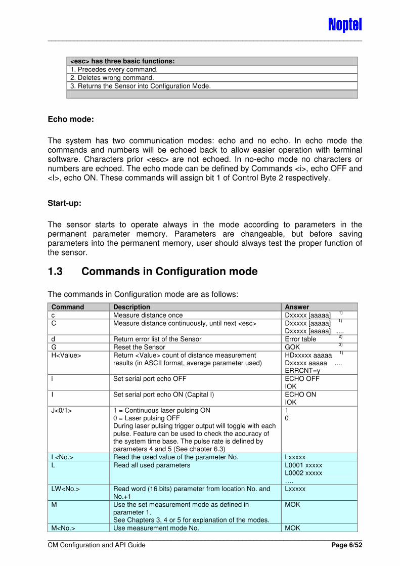
1.3 Commands in Configuration mode
The commands in Configuration mode are as follows:
Command Description Answer
c Measure distance once Dxxxxx [aaaaa] 1)
C Measure distance continuously, until next <esc> Dxxxxx [aaaaa] 1)
Dxxxxx [aaaaa] ....
d Return error list of the Sensor Error table 2)
G Reset the Sensor GOK 3)
H<Value> Return <Value> count of distance measurement results (in ASCII format, average parameter used)
HDxxxxx aaaaa 1)
Dxxxxx aaaaa .... ERRCNT=y
i Set serial port echo OFF ECHO OFF IOK
I Set serial port echo ON (Capital I) ECHO ON IOK
J<0/1> 1 = Continuous laser pulsing ON 0 = Laser pulsing OFF During laser pulsing trigger output will toggle with each pulse. Feature can be used to check the accuracy of the system time base. The pulse rate is defined by parameters 4 and 5 (See chapter 6.3)
1 0
L<No.> Read the used value of the parameter No. Lxxxxx
L Read all used parameters L0001 xxxxx L0002 xxxxx ….
LW<No.> Read word (16 bits) parameter from location No. and No.+1
Lxxxxx
M Use the set measurement mode as defined in parameter 1. See Chapters 3, 4 or 5 for explanation of the modes.
MOK
M<No.> Use measurement mode No. MOK

____________________________________________________________________________________
____________________________________________________________________________________ CM Configuration and API Guide Page 7/52
See Chapters 3, 4 or 5 for explanation of the modes.
O<0/1> 0 = pointer OFF, 1 = pointer ON OOK
P<No.> Read the value in EPROM of the parameter No. Pxxxxx
S Save user parameters into the permanent memory (X must be used before)
SOK
T<No.>,<Value> Write <Value> to the parameter <No.> (ram) TOK
TW<No.>,<Value Write integer <Value> (0-65535) to parameter <No.> and <No.>+1
TOK
v (lower case) Sensor information in the Noptel internal format
V (upper case) Sensor information in ASCII format (version) Sensor information 4)
V1 Read voltage, current and temperature measurements Table 5)
V2 Perform self-test and show its result OK or Explanation of the error and ERR:xxxxx
X Enable writing into the permanent memory WR ENABLE
Commonly used commands in configuring the sensor for applications are light blue. The end of the line of answer is always <cr><lf>.
1) Distance measurement commands
Commands c and C, return results according to Chapter 3.1.
With command H it’s the same except Amplitude Output Enable does not have an effect but amplitude is given in any case.
2) Error table (example) (table is for diagnostic purposes only and it is updated during every power-up of the sensor)
Code Error Error count
0001 EEPROM R/W : 0
0002 TDC datardy : 0
0004 RX Error : 0
0008 TDC main counter : 0
0010 TDC interpolator : 0
0020 Low battery : 0
0040 Supply voltage! : 0
0080 Invalid value : 0
0100 Unknown command : 0
0200 TDC interp zero : 0
0400 EEPROM/FLASH:CRC? : 0
0800 Voltage error! : 0
1000 APD voltage! : 0
2000 Temperature! : 0
4000 Power consumption! : 0
8000 HV error! : 0
OK
Some errors may occur in certain conditions, like too low supply voltage or too high/low operating temperature. If the operation of the sensor returns to normal and errors do not keep increasing, it is safe to continue using the sensor. Otherwise contact Noptel Oy for further information.
____________________________________________________________________________________
____________________________________________________________________________________ CM Configuration and API Guide Page 8/52
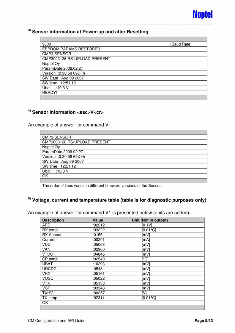
3) Sensor information at Power-up and after Resetting
9600 (Baud Rate)
EEPROM PARAMS RESTORED
CMP3-SENSOR
CMP3003126 RS-UPLOAD PRESENT
Noptel Oy
ParamDate:2006.02.27
Version :0.30.58 69DFh
SW Date :Aug 09 2007
SW time :12:51:12
Ubat :10.3 V
READY!
4) Sensor information <esc>V<cr>
An example of answer for command V:
CMP3-SENSOR
CMP3003126 RS-UPLOAD PRESENT
Noptel Oy
ParamDate:2006.02.27
Version :0.30.58 69DFh
SW Date :Aug 09 2007
SW time :12:51:12
Ubat :10.3 V
OK
The order of lines varies in different firmware versions of the Sensor.
5) Voltage, current and temperature table (table is for diagnostic purposes only)
An example of answer for command V1 is presented below (units are added):
Description Value Unit (Not in output)
APD :02212 [0.1V]
RX temp :03222 [0.01°C]
RX Anaout :0156 [mV]
Current :00201 [mA]
VDD :05068 [mV]
VAN :02960 [mV]
VTDC :04845 [mV]
CP temp :02540 [°C]
UBAT :10293 [mV]
UDCDC :0548 [mV]
VRX :05161 [mV]
VOSC :05022 [mV]
VTX :05138 [mV]
VCP :03348 [mV]
TXHV :00257 [V]
TX temp :02311 [0.01°C]
OK
____________________________________________________________________________________
____________________________________________________________________________________ CM Configuration and API Guide Page 9/52
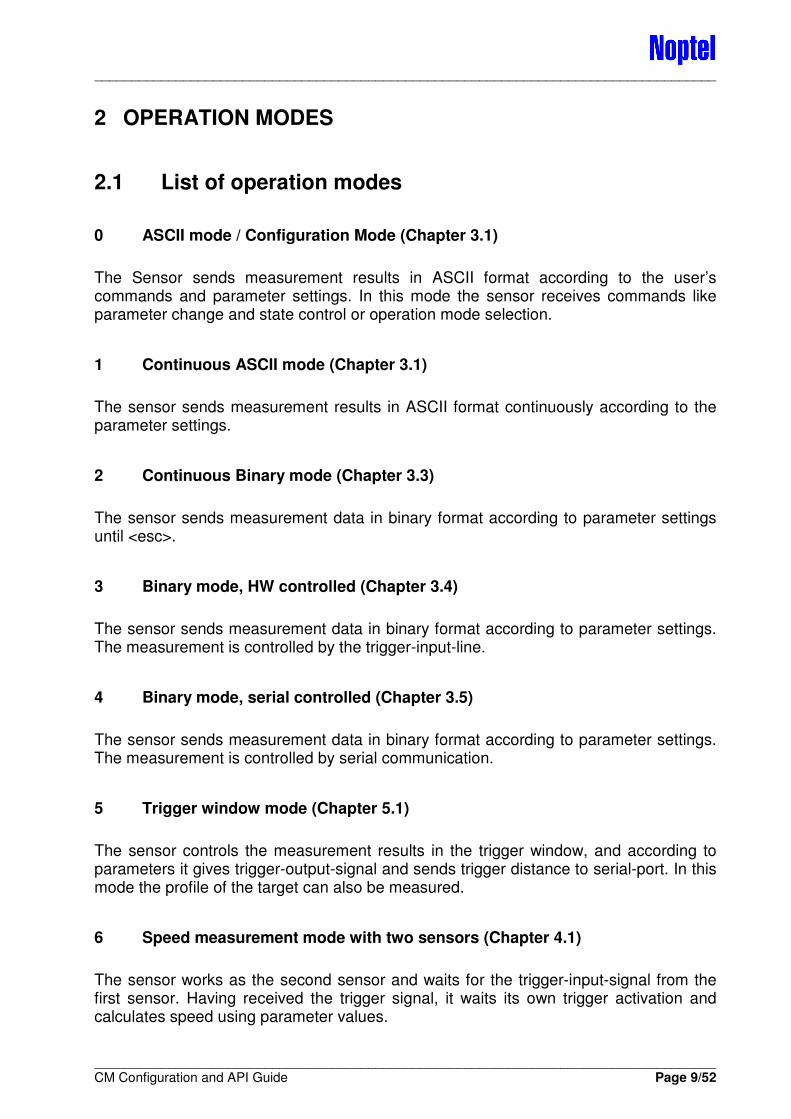
2 OPERATION MODES
2.1 List of operation modes
0 ASCII mode / Configuration Mode (Chapter 3.1)
The Sensor sends measurement results in ASCII format according to the user’s commands and parameter settings. In this mode the sensor receives commands like parameter change and state control or operation mode selection.
1 Continuous ASCII mode (Chapter 3.1)
The sensor sends measurement results in ASCII format continuously according to the parameter settings.
2 Continuous Binary mode (Chapter 3.3)
The sensor sends measurement data in binary format according to parameter settings until <esc>.
3 Binary mode, HW controlled (Chapter 3.4)
The sensor sends measurement data in binary format according to parameter settings. The measurement is controlled by the trigger-input-line.
4 Binary mode, serial controlled (Chapter 3.5)
The sensor sends measurement data in binary format according to parameter settings. The measurement is controlled by serial communication.
5 Trigger window mode (Chapter 5.1)
The sensor controls the measurement results in the trigger window, and according to parameters it gives trigger-output-signal and sends trigger distance to serial-port. In this mode the profile of the target can also be measured.
6 Speed measurement mode with two sensors (Chapter 4.1)
The sensor works as the second sensor and waits for the trigger-input-signal from the first sensor. Having received the trigger signal, it waits its own trigger activation and calculates speed using parameter values.
____________________________________________________________________________________
____________________________________________________________________________________ CM Configuration and API Guide Page 10/52
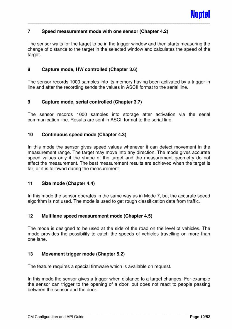
7 Speed measurement mode with one sensor (Chapter 4.2)
The sensor waits for the target to be in the trigger window and then starts measuring the change of distance to the target in the selected window and calculates the speed of the target.
8 Capture mode, HW controlled (Chapter 3.6)
The sensor records 1000 samples into its memory having been activated by a trigger in line and after the recording sends the values in ASCII format to the serial line.
9 Capture mode, serial controlled (Chapter 3.7)
The sensor records 1000 samples into storage after activation via the serial communication line. Results are sent in ASCII format to the serial line.
10 Continuous speed mode (Chapter 4.3)
In this mode the sensor gives speed values whenever it can detect movement in the measurement range. The target may move into any direction. The mode gives accurate speed values only if the shape of the target and the measurement geometry do not affect the measurement. The best measurement results are achieved when the target is far, or it is followed during the measurement.
11 Size mode (Chapter 4.4)
In this mode the sensor operates in the same way as in Mode 7, but the accurate speed algorithm is not used. The mode is used to get rough classification data from traffic.
12 Multilane speed measurement mode (Chapter 4.5)
The mode is designed to be used at the side of the road on the level of vehicles. The mode provides the possibility to catch the speeds of vehicles travelling on more than one lane.
13 Movement trigger mode (Chapter 5.2)
The feature requires a special firmware which is available on request.
In this mode the sensor gives a trigger when distance to a target changes. For example the sensor can trigger to the opening of a door, but does not react to people passing between the sensor and the door.

____________________________________________________________________________________
____________________________________________________________________________________ CM Configuration and API Guide Page 11/52
2.2 Output at starting of the operation mode
Output of the Sensor after mode command (<esc>M<No.><cr>) are following:
Mode <No.> Output
0 MOK, no effect
1 MOK Dxxxxx [aaaaa] Dxxxxx [aaaaa] ....
2 MOK (Binary format distances)
3 MOK HW BINARY MODE ESC to EXIT
4 MOK RS BINARY MODE ESC to EXIT
5 (example) MOK TRIGGER MODE TRIG IN 500–550 cm ESC to EXIT
6 (example) MOK TWO DEVICE SPEED MODE TRIG IN 500–550 cm ESC to EXIT
7 (example) MOK SINGLE DEVICE SPEED MODE Approaching vehicles mode Speed window size : 100 cm TRIG IN 2000–2500cm ESC to EXIT
8 MOK ESC to EXIT HW CAPTURE MODE (1000 SAMPLES)
9 RS CAPTURE MODE (1000 SAMPLES) ESC to EXIT
10 CONTINUOUS SPEED MODE. ESC TO EXIT
11 (example) SINGLE DEVICE SIZE MODE Departing vehicles mode Speed window size : 300 cm Vehicle classification activated. TRIG IN 2460–2960 cm ESC to EXIT
12 (example) MULTILANE SINGLE DEVICE SPEED MODE Lane Configuration: Approaching : 5 - 20 m. Departing : 20 - 45 m. Speed window size : 100 cm TRIG IN 500- 4500 cm ESC to EXIT
13 (example) MOVEMENT TRIGGER MODE Reference distance : 995 cm TRIG IN 945- 1045 cm ESC to EXIT
____________________________________________________________________________________
____________________________________________________________________________________ CM Configuration and API Guide Page 12/52
3 DISTANCE MEASUREMENTS
3.1 ASCII Mode
The value of the Parameter 1 is 0 (= single) or 1 (= continuous).
In this mode the sensor measures the distance to the target either after the detection of <space> character or by the activation of Digital-input-signal or by the user command (c or C). Serial port communication is in ASCII format. The maximum measurement speed in ASCII mode depends on the communication speed and parameter settings. Continuous mode can be activated by command <esc>M1<cr> or <esc>M<cr> if value of par. #1 is 1.
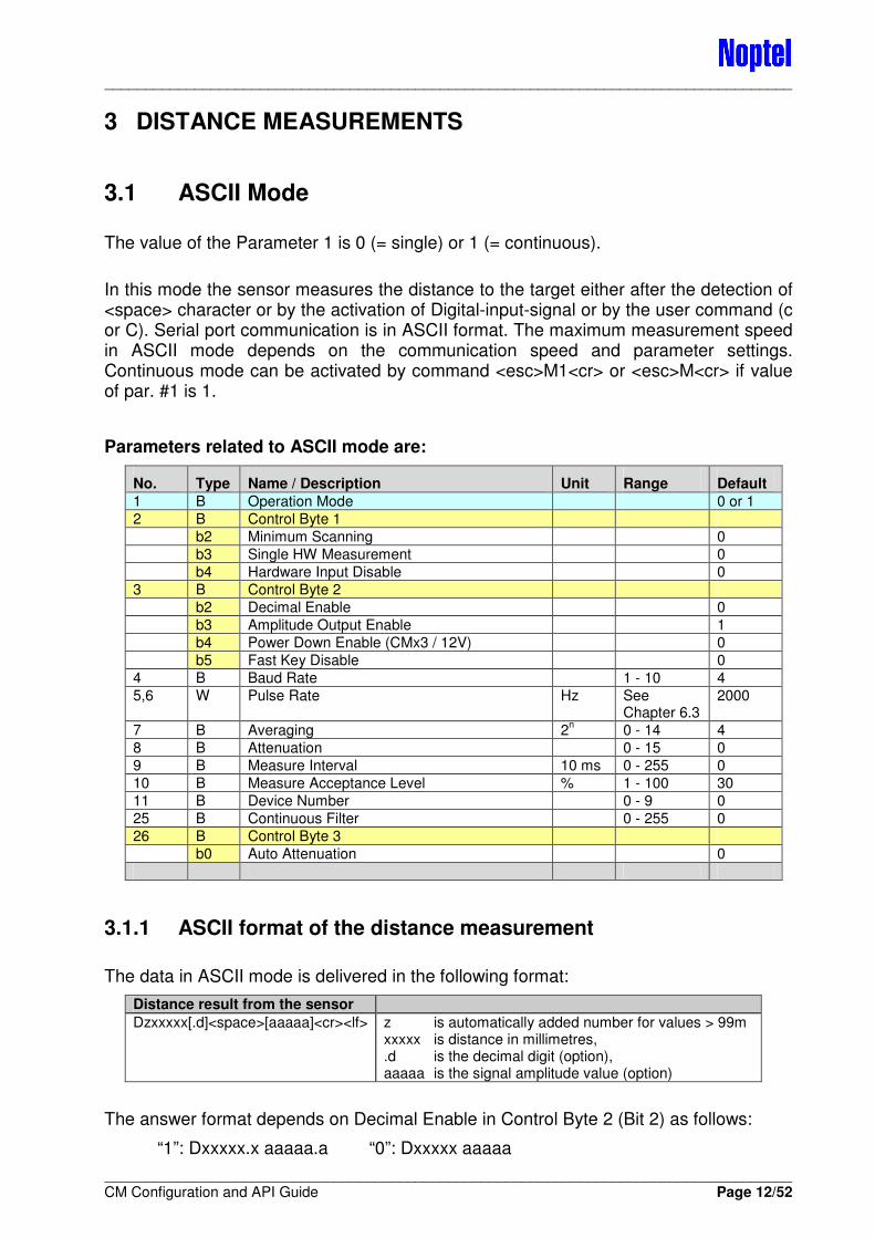
Parameters related to ASCII mode are:
No. Type Name / Description Unit Range Default
1 B Operation Mode 0 or 1
2 B Control Byte 1
b2 Minimum Scanning 0
b3 Single HW Measurement 0
b4 Hardware Input Disable 0
3 B Control Byte 2
b2 Decimal Enable 0
b3 Amplitude Output Enable 1
b4 Power Down Enable (CMx3 / 12V) 0
b5 Fast Key Disable 0
4 B Baud Rate 1 - 10 4
5,6 W Pulse Rate Hz See Chapter 6.3
2000
7 B Averaging 2n 0 - 14 4
8 B Attenuation 0 - 15 0
9 B Measure Interval 10 ms 0 - 255 0
10 B Measure Acceptance Level % 1 - 100 30
11 B Device Number 0 - 9 0
25 B Continuous Filter 0 - 255 0
26 B Control Byte 3
b0 Auto Attenuation 0
3.1.1 ASCII format of the distance measurement
The data in ASCII mode is delivered in the following format:
Distance result from the sensor
Dzxxxxx[.d]<space>[aaaaa]<cr><lf> z is automatically added number for values > 99m xxxxx is distance in millimetres, .d is the decimal digit (option), aaaaa is the signal amplitude value (option)
The answer format depends on Decimal Enable in Control Byte 2 (Bit 2) as follows:
“1”: Dxxxxx.x aaaaa.a “0”: Dxxxxx aaaaa
____________________________________________________________________________________
____________________________________________________________________________________ CM Configuration and API Guide Page 13/52
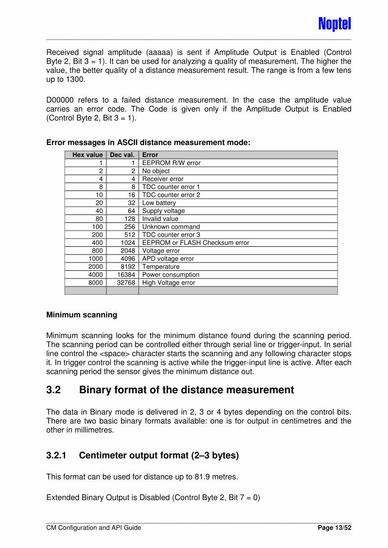
Received signal amplitude (aaaaa) is sent if Amplitude Output is Enabled (Control Byte 2, Bit 3 = 1). It can be used for analyzing a quality of measurement. The higher the value, the better quality of a distance measurement result. The range is from a few tens up to 1300.
D00000 refers to a failed distance measurement. In the case the amplitude value carries an error code. The Code is given only if the Amplitude Output is Enabled (Control Byte 2, Bit 3 = 1).
Error messages in ASCII distance measurement mode:
Hex value Dec val. Error
1 1 EEPROM R/W error
2 2 No object
4 4 Receiver error
8 8 TDC counter error 1
10 16 TDC counter error 2
20 32 Low battery
40 64 Supply voltage
80 128 Invalid value
100 256 Unknown command
200 512 TDC counter error 3
400 1024 EEPROM or FLASH Checksum error
800 2048 Voltage error
1000 4096 APD voltage error
2000 8192 Temperature
4000 16384 Power consumption
8000 32768 High Voltage error
Minimum scanning
Minimum scanning looks for the minimum distance found during the scanning period. The scanning period can be controlled either through serial line or trigger-input. In serial line control the <space> character starts the scanning and any following character stops it. In trigger control the scanning is active while the trigger-input line is active. After each scanning period the sensor gives the minimum distance out.
3.2 Binary format of the distance measurement
The data in Binary mode is delivered in 2, 3 or 4 bytes depending on the control bits. There are two basic binary formats available: one is for output in centimetres and the other in millimetres.
3.2.1 Centimeter output format (2–3 bytes)
This format can be used for distance up to 81.9 metres.
Extended Binary Output is Disabled (Control Byte 2, Bit 7 = 0)
____________________________________________________________________________________
____________________________________________________________________________________ CM Configuration and API Guide Page 14/52
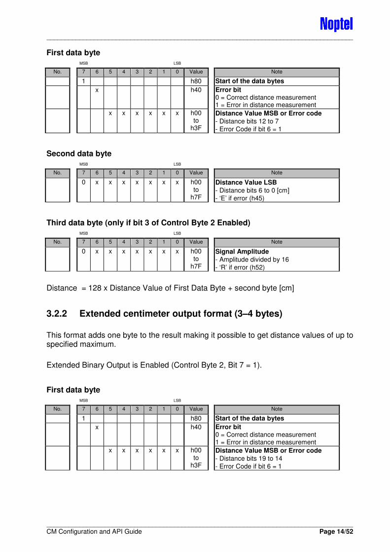
First data byte MSB LSB
No. 7 6 5 4 3 2 1 0 Value Note
1 h80 Start of the data bytes
x h40 Error bit 0 = Correct distance measurement 1 = Error in distance measurement
x x x x x x h00 to
h3F
Distance Value MSB or Error code
- Distance bits 12 to 7
- Error Code if bit 6 = 1
Second data byte MSB LSB
No. 7 6 5 4 3 2 1 0 Value Note
0 x x x x x x x h00 to
h7F
Distance Value LSB
- Distance bits 6 to 0 [cm]
- ‘E’ if error (h45)
Third data byte (only if bit 3 of Control Byte 2 Enabled) MSB LSB
No. 7 6 5 4 3 2 1 0 Value Note
0 x x x x x x x h00 to
h7F
Signal Amplitude
- Amplitude divided by 16
- ‘R’ if error (h52)
Distance = 128 x Distance Value of First Data Byte + second byte [cm]
3.2.2 Extended centimeter output format (3–4 bytes)
This format adds one byte to the result making it possible to get distance values of up to specified maximum.
Extended Binary Output is Enabled (Control Byte 2, Bit 7 = 1).
First data byte MSB LSB
No. 7 6 5 4 3 2 1 0 Value Note
1 h80 Start of the data bytes
x h40 Error bit 0 = Correct distance measurement 1 = Error in distance measurement
x x x x x x h00 to
h3F
Distance Value MSB or Error code
- Distance bits 19 to 14
- Error Code if bit 6 = 1

____________________________________________________________________________________
____________________________________________________________________________________ CM Configuration and API Guide Page 15/52
Second data byte MSB LSB
No. 7 6 5 4 3 2 1 0 Value Note
0 x x x x x x x h00 to
h7F
Distance Value
- Distance bits 13 to 7
- ‘E’ if error (h45)
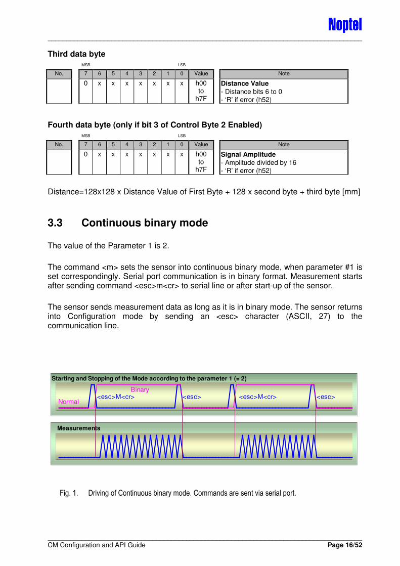
Third data byte MSB LSB
No. 7 6 5 4 3 2 1 0 Value Note
0 x x x x x x x h00 to
h7F
Distance Value
- Distance bits 6 to 0 [cm]
- ‘R’ if error (h52)
Fourth data byte (only if bit 3 of Control Byte 2 Enabled) MSB LSB
No. 7 6 5 4 3 2 1 0 Value Note
0 x x x x x x x h00 to
h7F
Signal Amplitude
- Amplitude divided by 16
- ‘R’ if error (h52)
Distance = 128x128 x Dist. Value of First Byte + 128 x second byte + third byte [cm]
3.2.3 Millimeter output format (3–4 bytes)
The format can be enabled by setting Millimetre Binary Output (Control Byte 2, Bit 6=1).
Extended Binary Output (Control Byte 2, Bit 7 = x) does not have effect.
First data byte MSB LSB
No. 7 6 5 4 3 2 1 0 Value Note
1 h80 Start of the data bytes
x h40 Error bit 0 = Correct distance measurement 1 = Error in distance measurement
x x x x x x h00 to
h3F
Distance Value MSB or Error code
- Distance bits 19 to 14
- Error Code if bit 6 = 1
Second data byte MSB LSB
No. 7 6 5 4 3 2 1 0 Value Note
0 x x x x x x x h00 to
h7F
Distance Value
- Distance bits 13 to 7
- ‘E’ if error (h45)
____________________________________________________________________________________
____________________________________________________________________________________ CM Configuration and API Guide Page 16/52
Third data byte MSB LSB
No. 7 6 5 4 3 2 1 0 Value Note
0 x x x x x x x h00 to
h7F
Distance Value
- Distance bits 6 to 0
- ‘R’ if error (h52)
Fourth data byte (only if bit 3 of Control Byte 2 Enabled) MSB LSB
No. 7 6 5 4 3 2 1 0 Value Note
0 x x x x x x x h00 to
h7F
Signal Amplitude
- Amplitude divided by 16
- ‘R’ if error (h52)
Distance=128x128 x Distance Value of First Byte + 128 x second byte + third byte [mm]
3.3 Continuous binary mode
The value of the Parameter 1 is 2.
The command <m> sets the sensor into continuous binary mode, when parameter #1 is set correspondingly. Serial port communication is in binary format. Measurement starts after sending command <esc>m<cr> to serial line or after start-up of the sensor.
The sensor sends measurement data as long as it is in binary mode. The sensor returns into Configuration mode by sending an <esc> character (ASCII, 27) to the communication line.
Fig. 1. Driving of Continuous binary mode. Commands are sent via serial port.
Starting and Stopping of the Mode according to the parameter 1 (= 2)
<esc>M<cr> <esc>Binary
Normal<esc> <esc>M<cr>
Measurements

____________________________________________________________________________________
____________________________________________________________________________________ CM Configuration and API Guide Page 17/52
Parameters related to Continuous Binary mode are:
No. Type Name / Description Unit Range Default
1 B Operation Mode 2
3 B Control Byte 2
b3 Amplitude Output Enable 0
b6 Millimetre Binary Output (Note 1) ** 0
b7 Extended Binary Output (Note 1) 0
4 B Baud Rate (Note 2) 1 - 10 4 5,6 W Pulse Rate Hz See
Chapter 6.3 2000
8 B Attenuation 0 - 15 0
11 B Device Number 0 - 9 0
22 B Binary Average ** (In millimetre mode only) 2n 0 - 14 0
The suggested max rate for continuous measurement depends on the model, and the minimum rate is 50 Hz. Special, high pulse rate versions of the sensor are available on request.
Note 1: Millimetre or Extended Binary output is not available in high pulse rate versions!
Note 2: If the communication speed is too low it constrains the maximum measurement speed.
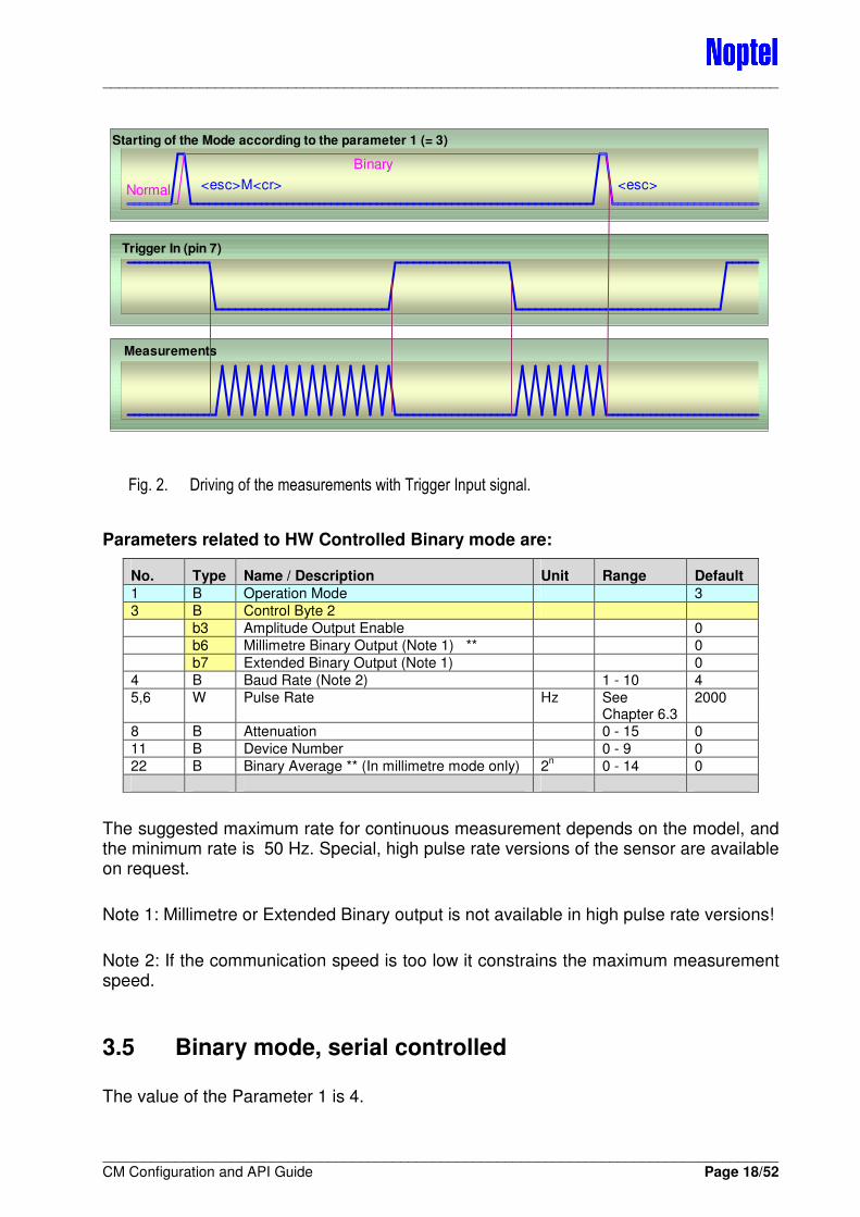
3.4 Binary mode, HW controlled
The value of the Parameter 1 is 3.
The command <m> sets the sensor into hardware controlled binary mode, when the parameter 1 is set correspondingly. Serial port communication is in binary format.
Measurement starts by pulling the trigger-input down. This is done by connecting pin 7 in the I/O-connector to ground (pin 2). See connection table in Technical Manual.
Measurement starts after 20 µs +/- 1 µs delay from the activation. The sensor sends measurement data as long as the line is activated (low). Measuring stops after the line has been deactivated (set high) and starts again at new activation. When the sensor is in HW-controlled mode, measurement is always on when the trigger line is active (low).
The sensor will return into Configuration mode by sending an <esc> character to the communication line. Stopping the Binary mode is possible during measurements or in pause.
____________________________________________________________________________________
____________________________________________________________________________________ CM Configuration and API Guide Page 18/52
Fig. 2. Driving of the measurements with Trigger Input signal.
Parameters related to HW Controlled Binary mode are:
No. Type Name / Description Unit Range Default
1 B Operation Mode 3
3 B Control Byte 2
b3 Amplitude Output Enable 0
b6 Millimetre Binary Output (Note 1) ** 0
b7 Extended Binary Output (Note 1) 0
4 B Baud Rate (Note 2) 1 - 10 4
5,6 W Pulse Rate Hz See Chapter 6.3
2000
8 B Attenuation 0 - 15 0
11 B Device Number 0 - 9 0
22 B Binary Average ** (In millimetre mode only) 2n 0 - 14 0
The suggested maximum rate for continuous measurement depends on the model, and the minimum rate is 50 Hz. Special, high pulse rate versions of the sensor are available on request.
Note 1: Millimetre or Extended Binary output is not available in high pulse rate versions!
Note 2: If the communication speed is too low it constrains the maximum measurement speed.
3.5 Binary mode, serial controlled
The value of the Parameter 1 is 4.
Trigger In (pin 7)
Starting of the Mode according to the parameter 1 (= 3)
<esc>M<cr> <esc>
Binary
Normal
Measurements
____________________________________________________________________________________
____________________________________________________________________________________ CM Configuration and API Guide Page 19/52
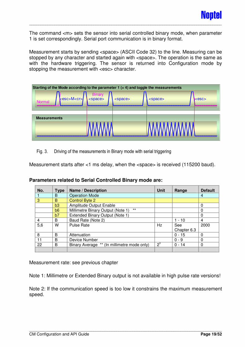
The command <m> sets the sensor into serial controlled binary mode, when parameter 1 is set correspondingly. Serial port communication is in binary format.
Measurement starts by sending <space> (ASCII Code 32) to the line. Measuring can be stopped by any character and started again with <space>. The operation is the same as with the hardware triggering. The sensor is returned into Configuration mode by stopping the measurement with <esc> character.
Fig. 3. Driving of the measurements in Binary mode with serial triggering
Measurement starts after <1 ms delay, when the <space> is received (115200 baud).
Parameters related to Serial Controlled Binary mode are:
No. Type Name / Description Unit Range Default
1 B Operation Mode 4
3 B Control Byte 2
b3 Amplitude Output Enable 0
b6 Millimetre Binary Output (Note 1) ** 0
b7 Extended Binary Output (Note 1) 0
4 B Baud Rate (Note 2) 1 - 10 4
5,6 W Pulse Rate Hz See Chapter 6.3
2000
8 B Attenuation 0 - 15 0
11 B Device Number 0 - 9 0
22 B Binary Average ** (In millimetre mode only) 2n 0 - 14 0
Measurement rate: see previous chapter
Note 1: Millimetre or Extended Binary output is not available in high pulse rate versions!
Note 2: If the communication speed is too low it constrains the maximum measurement speed.
Starting of the Mode according to the parameter 1 (= 4) and toggle the measurements
<esc>M<cr> <esc>Binary
Normal<space> <space><space>
Measurements
____________________________________________________________________________________
____________________________________________________________________________________ CM Configuration and API Guide Page 20/52
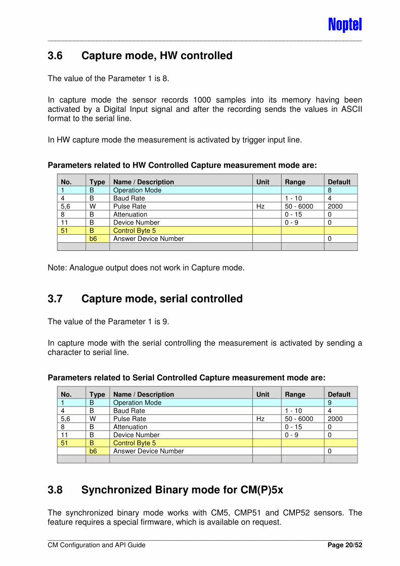
3.6 Capture mode, HW controlled
The value of the Parameter 1 is 8.
In capture mode the sensor records 1000 samples into its memory having been activated by a Digital Input signal and after the recording sends the values in ASCII format to the serial line.
In HW capture mode the measurement is activated by trigger input line.
Parameters related to HW Controlled Capture measurement mode are:
No. Type Name / Description Unit Range Default
1 B Operation Mode 8
4 B Baud Rate 1 - 10 4
5,6 W Pulse Rate Hz 50 - 6000 2000
8 B Attenuation 0 - 15 0
11 B Device Number 0 - 9 0
51 B Control Byte 5
b6 Answer Device Number 0
Note: Analogue output does not work in Capture mode.
3.7 Capture mode, serial controlled
The value of the Parameter 1 is 9.
In capture mode with the serial controlling the measurement is activated by sending a character to serial line.
Parameters related to Serial Controlled Capture measurement mode are:
No. Type Name / Description Unit Range Default
1 B Operation Mode 9
4 B Baud Rate 1 - 10 4
5,6 W Pulse Rate Hz 50 - 6000 2000
8 B Attenuation 0 - 15 0
11 B Device Number 0 - 9 0
51 B Control Byte 5
b6 Answer Device Number 0
3.8 Synchronized Binary mode for CM(P)5x
The synchronized binary mode works with CM5, CMP51 and CMP52 sensors. The feature requires a special firmware, which is available on request.
____________________________________________________________________________________
____________________________________________________________________________________ CM Configuration and API Guide Page 21/52
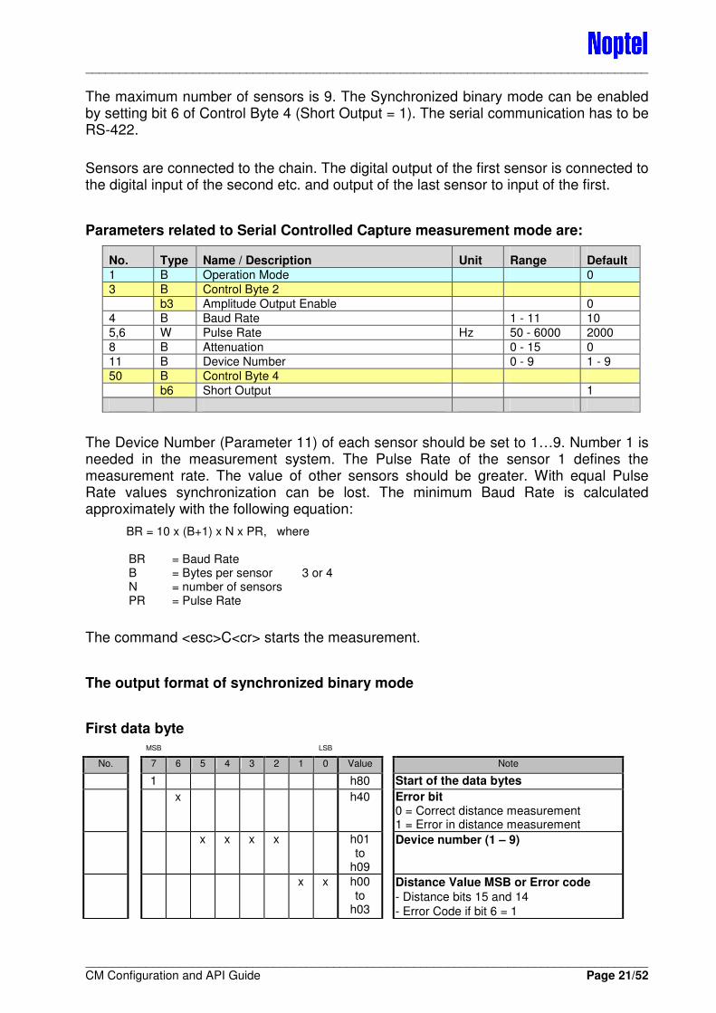
The maximum number of sensors is 9. The Synchronized binary mode can be enabled by setting bit 6 of Control Byte 4 (Short Output = 1). The serial communication has to be RS-422.
Sensors are connected to the chain. The digital output of the first sensor is connected to the digital input of the second etc. and output of the last sensor to input of the first.
Parameters related to Serial Controlled Capture measurement mode are:
No. Type Name / Description Unit Range Default
1 B Operation Mode 0
3 B Control Byte 2
b3 Amplitude Output Enable 0
4 B Baud Rate 1 - 11 10
5,6 W Pulse Rate Hz 50 - 6000 2000
8 B Attenuation 0 - 15 0
11 B Device Number 0 - 9 1 - 9
50 B Control Byte 4
b6 Short Output 1
The Device Number (Parameter 11) of each sensor should be set to 1…9. Number 1 is needed in the measurement system. The Pulse Rate of the sensor 1 defines the measurement rate. The value of other sensors should be greater. With equal Pulse Rate values synchronization can be lost. The minimum Baud Rate is calculated approximately with the following equation:
BR = 10 x (B+1) x N x PR, where BR = Baud Rate B = Bytes per sensor 3 or 4 N = number of sensors PR = Pulse Rate
The command <esc>C<cr> starts the measurement.
The output format of synchronized binary mode
First data byte MSB LSB
No. 7 6 5 4 3 2 1 0 Value Note
1 h80 Start of the data bytes
x h40 Error bit 0 = Correct distance measurement 1 = Error in distance measurement
x x x x h01 to
h09
Device number (1 – 9)
x x h00 to
h03
Distance Value MSB or Error code
- Distance bits 15 and 14
- Error Code if bit 6 = 1
____________________________________________________________________________________
____________________________________________________________________________________ CM Configuration and API Guide Page 22/52
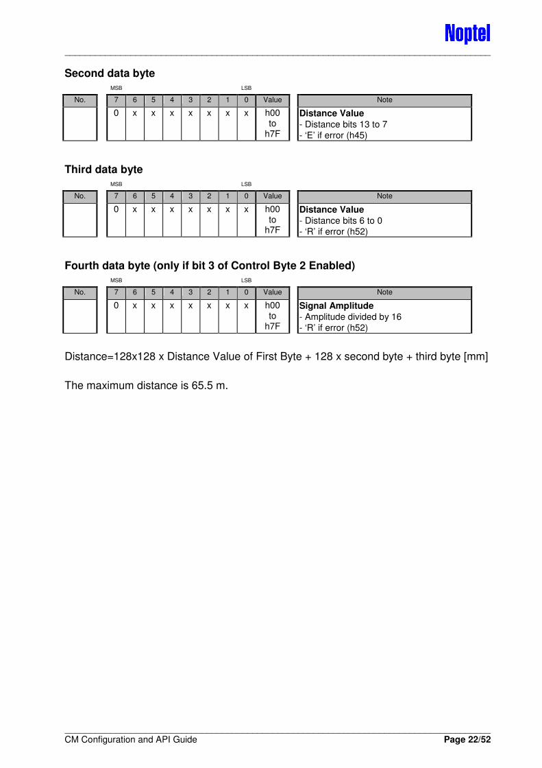
Second data byte MSB LSB
No. 7 6 5 4 3 2 1 0 Value Note
0 x x x x x x x h00 to
h7F
Distance Value
- Distance bits 13 to 7
- ‘E’ if error (h45)
Third data byte MSB LSB
No. 7 6 5 4 3 2 1 0 Value Note
0 x x x x x x x h00 to
h7F
Distance Value
- Distance bits 6 to 0
- ‘R’ if error (h52)
Fourth data byte (only if bit 3 of Control Byte 2 Enabled) MSB LSB
No. 7 6 5 4 3 2 1 0 Value Note
0 x x x x x x x h00 to
h7F
Signal Amplitude
- Amplitude divided by 16
- ‘R’ if error (h52)
Distance=128x128 x Distance Value of First Byte + 128 x second byte + third byte [mm]
The maximum distance is 65.5 m.
____________________________________________________________________________________
____________________________________________________________________________________ CM Configuration and API Guide Page 23/52
4 SPEED MEASUREMENTS
4.1 Speed measurement mode with two sensors
The value of the Parameter 1 for Sensor 1 is 5 and for Sensor 2 is 6.
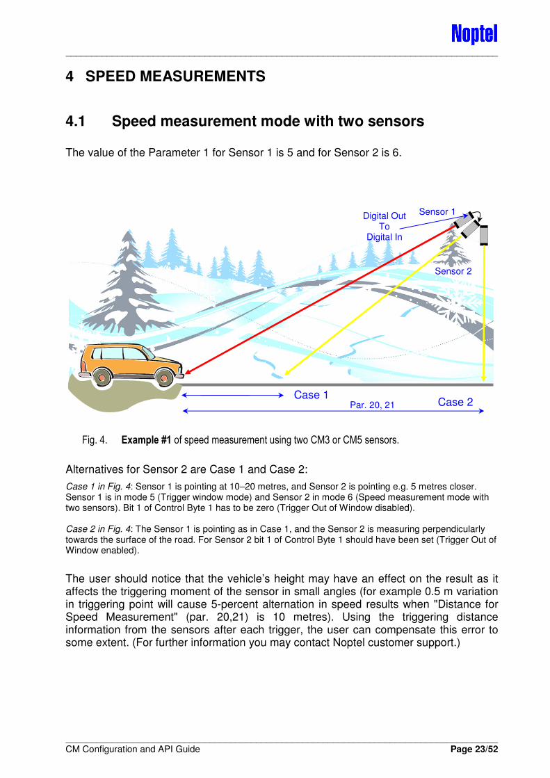
Fig. 4. Example #1 of speed measurement using two CM3 or CM5 sensors.
Alternatives for Sensor 2 are Case 1 and Case 2:
Case 1 in Fig. 4: Sensor 1 is pointing at 10–20 metres, and Sensor 2 is pointing e.g. 5 metres closer. Sensor 1 is in mode 5 (Trigger window mode) and Sensor 2 in mode 6 (Speed measurement mode with two sensors). Bit 1 of Control Byte 1 has to be zero (Trigger Out of Window disabled). Case 2 in Fig. 4: The Sensor 1 is pointing as in Case 1, and the Sensor 2 is measuring perpendicularly towards the surface of the road. For Sensor 2 bit 1 of Control Byte 1 should have been set (Trigger Out of Window enabled).
The user should notice that the vehicle’s height may have an effect on the result as it affects the triggering moment of the sensor in small angles (for example 0.5 m variation in triggering point will cause 5-percent alternation in speed results when "Distance for Speed Measurement" (par. 20,21) is 10 metres). Using the triggering distance information from the sensors after each trigger, the user can compensate this error to some extent. (For further information you may contact Noptel customer support.)
Case 1 Case 2 Par. 20, 21
Sensor 1
Sensor 2
Digital Out To
Digital In
____________________________________________________________________________________
____________________________________________________________________________________ CM Configuration and API Guide Page 24/52
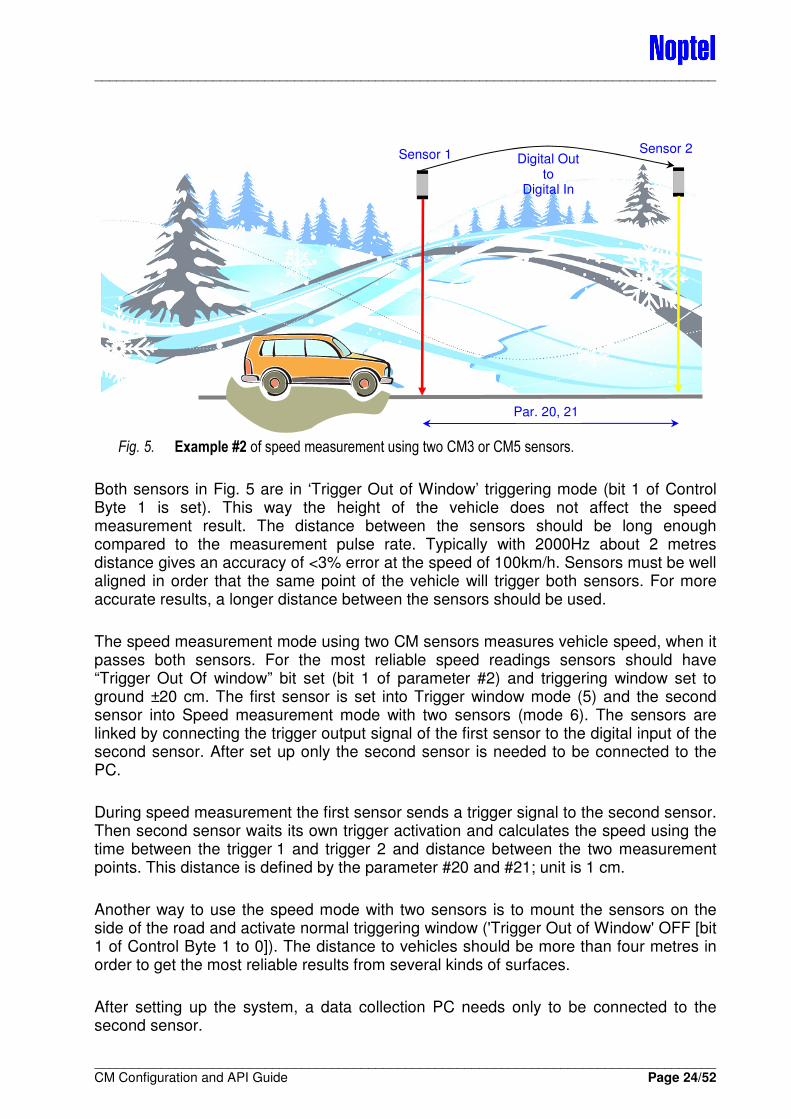
Fig. 5. Example #2 of speed measurement using two CM3 or CM5 sensors.
Both sensors in Fig. 5 are in ‘Trigger Out of Window’ triggering mode (bit 1 of Control Byte 1 is set). This way the height of the vehicle does not affect the speed measurement result. The distance between the sensors should be long enough compared to the measurement pulse rate. Typically with 2000Hz about 2 metres distance gives an accuracy of <3% error at the speed of 100km/h. Sensors must be well aligned in order that the same point of the vehicle will trigger both sensors. For more accurate results, a longer distance between the sensors should be used.
The speed measurement mode using two CM sensors measures vehicle speed, when it passes both sensors. For the most reliable speed readings sensors should have “Trigger Out Of window” bit set (bit 1 of parameter #2) and triggering window set to ground ±20 cm. The first sensor is set into Trigger window mode (5) and the second sensor into Speed measurement mode with two sensors (mode 6). The sensors are linked by connecting the trigger output signal of the first sensor to the digital input of the second sensor. After set up only the second sensor is needed to be connected to the PC.
During speed measurement the first sensor sends a trigger signal to the second sensor. Then second sensor waits its own trigger activation and calculates the speed using the time between the trigger 1 and trigger 2 and distance between the two measurement points. This distance is defined by the parameter #20 and #21; unit is 1 cm.
Another way to use the speed mode with two sensors is to mount the sensors on the side of the road and activate normal triggering window ('Trigger Out of Window' OFF [bit 1 of Control Byte 1 to 0]). The distance to vehicles should be more than four metres in order to get the most reliable results from several kinds of surfaces.
After setting up the system, a data collection PC needs only to be connected to the second sensor.
Sensor 1
Par. 20, 21
Sensor 2 Digital Out
to Digital In
____________________________________________________________________________________
____________________________________________________________________________________ CM Configuration and API Guide Page 25/52
Note: In this mode the sensor sends an “OK” message every minute, if it is functional.
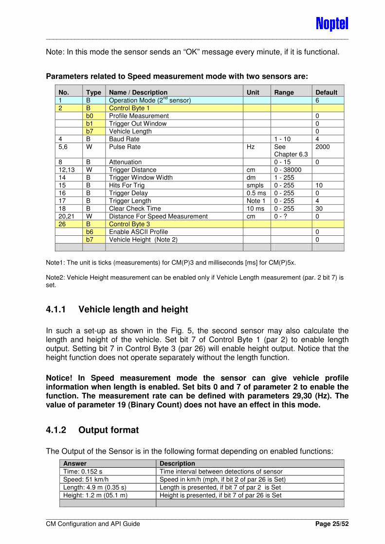
Parameters related to Speed measurement mode with two sensors are:
No. Type Name / Description Unit Range Default
1 B Operation Mode (2nd
sensor) 6
2 B Control Byte 1
b0 Profile Measurement 0
b1 Trigger Out Window 0 b7 Vehicle Length 0
4 B Baud Rate 1 - 10 4
5,6 W Pulse Rate Hz See Chapter 6.3
2000
8 B Attenuation 0 - 15 0
12,13 W Trigger Distance cm 0 - 38000
14 B Trigger Window Width dm 1 - 255
15 B Hits For Trig smpls 0 - 255 10
16 B Trigger Delay 0.5 ms 0 - 255 0
17 B Trigger Length Note 1 0 - 255 4
18 B Clear Check Time 10 ms 0 - 255 30
20,21 W Distance For Speed Measurement cm 0 - ? 0
26 B Control Byte 3
b6 Enable ASCII Profile 0
b7 Vehicle Height (Note 2) 0
Note1: The unit is ticks (measurements) for CM(P)3 and milliseconds [ms] for CM(P)5x. Note2: Vehicle Height measurement can be enabled only if Vehicle Length measurement (par. 2 bit 7) is set.
4.1.1 Vehicle length and height
In such a set-up as shown in the Fig. 5, the second sensor may also calculate the length and height of the vehicle. Set bit 7 of Control Byte 1 (par 2) to enable length output. Setting bit 7 in Control Byte 3 (par 26) will enable height output. Notice that the height function does not operate separately without the length function.
Notice! In Speed measurement mode the sensor can give vehicle profile information when length is enabled. Set bits 0 and 7 of parameter 2 to enable the function. The measurement rate can be defined with parameters 29,30 (Hz). The value of parameter 19 (Binary Count) does not have an effect in this mode.
4.1.2 Output format
The Output of the Sensor is in the following format depending on enabled functions:
Answer Description
Time: 0.152 s Time interval between detections of sensor
Speed: 51 km/h Speed in km/h (mph, if bit 2 of par 26 is Set)
Length: 4.9 m (0.35 s) Length is presented, if bit 7 of par 2 is Set
Height: 1.2 m (05.1 m) Height is presented, if bit 7 of par 26 is Set
____________________________________________________________________________________
____________________________________________________________________________________ CM Configuration and API Guide Page 26/52
The value 0.35 s is the time the vehicle/target was in the sensor’s measurement area.
Height is calculated from the shortest measured distance during length measurement (in this case 5.1 m) by subtracting the triggering window distance (par 12,13). In this example the trigger window has been at 6.3 metres (par 12,13 = 630).
4.2 Speed measurement mode with one sensor
The value of the Parameter 1 is 7.
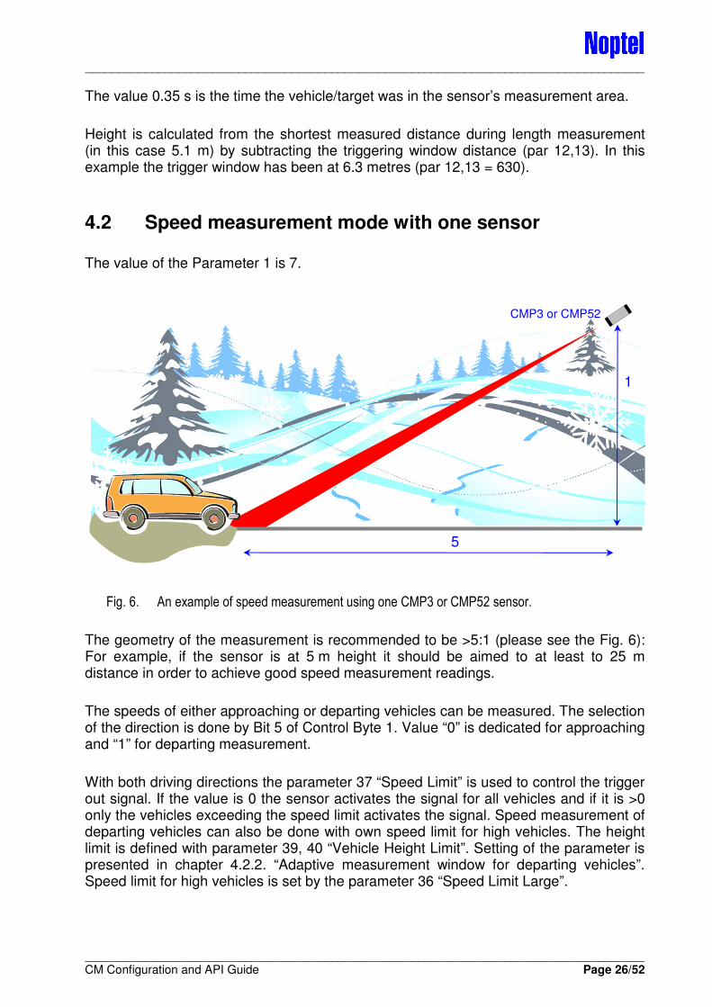
Fig. 6. An example of speed measurement using one CMP3 or CMP52 sensor.
The geometry of the measurement is recommended to be >5:1 (please see the Fig. 6): For example, if the sensor is at 5 m height it should be aimed to at least to 25 m distance in order to achieve good speed measurement readings.
The speeds of either approaching or departing vehicles can be measured. The selection of the direction is done by Bit 5 of Control Byte 1. Value “0” is dedicated for approaching and “1” for departing measurement.
With both driving directions the parameter 37 “Speed Limit” is used to control the trigger out signal. If the value is 0 the sensor activates the signal for all vehicles and if it is >0 only the vehicles exceeding the speed limit activates the signal. Speed measurement of departing vehicles can also be done with own speed limit for high vehicles. The height limit is defined with parameter 39, 40 “Vehicle Height Limit”. Setting of the parameter is presented in chapter 4.2.2. “Adaptive measurement window for departing vehicles”. Speed limit for high vehicles is set by the parameter 36 “Speed Limit Large”.
1
5
CMP3 or CMP52

____________________________________________________________________________________
____________________________________________________________________________________ CM Configuration and API Guide Page 27/52
Control Byte 5 (par 51), Bit 1, “Show Violation Only”, controls the output of the sensor in speed measurement so that the results are sent only for cases exceeding the Speed Limit (par 37) or Speed Limit Large (par 36).
In order to use the mode user must set following parameters:
No. Type Name / Description Unit Range Default
1 B Operation Mode 7
2 B Control Byte 1 b5 Speed Behind 0
b7 Vehicle Length (Note 1) 0
4 B Baud Rate 1 - 10 4
5,6 W Pulse Rate Hz See Chapter 6.3
2000
8 B Attenuation 0 - 15 0
12,13 W Trigger Distance cm 0 - 38000
14 B Trigger Window Width dm 1 - 255
15 B Hits For Trig smpls 0 - 255 10
16 B Trigger Delay 0.5 ms 0 - 255 0
17 B Trigger Length Note 2 0 - 255 4
18 B Clear Check Time 10 ms 0 - 255 30
26 B Control Byte 3
b1 Disable Ok Text 0
b2 Speed Output 0: km/h 1: MPH 0
b3 Show Speed Histogram 0
b7 Vehicle Height 0
Note 1: The vehicle length (= Size) is an estimation based on the speed and the time the sensor is able to get measurements from a vehicle. This principle generates longer value for higher vehicle than its real length is. Note2: The unit is ticks (measurements) for CM(P)3 and milliseconds [ms] for CM(P)5x.
Speed parameters for the speed measurement with one sensor:
No. Type Name / Description Unit Range Default
28 B Speed Calculation Window dm 20 - 40 20
29,30 W Speed Pulse Rate Hz See Chapter 6.3
3000
31 B Speed Calculation Start dm 2 - 10 10
32 B Speed Geometry (Note 1) dm
33 B Speed Result Ctrl (see next paragraphs) 0 - 4
34 B Separation limit 0.1 s 0 - 255 0
35 B Speed Filter Length (35 + value x 5) 0 - 10 5
36 B Speed Limit Large km/h
37 B Speed Limit km/h
38 B Speed Accept Limit (behind 2, front 5) 0 - 10
39,40 W Vehicle Height Limit cm 200 - 1000
Note 1: Height of the sensor from the triggering point (= Speed Geometry) can be used to compensate the error caused by the geometry of the measurement set-up. The user can basically adjust the speed result slightly by using this parameter. The higher the value, the bigger the speed result the sensor indicates. Speed Geometry parameter may also be used when the sensor is installed on the side of the road at the level of vehicles to compensate the angle error of the measurement.
____________________________________________________________________________________
____________________________________________________________________________________ CM Configuration and API Guide Page 28/52
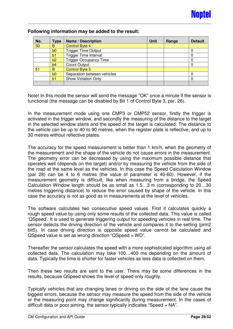
Following information may be added to the result:
No. Type Name / Description Unit Range Default
50 B Control Byte 4
b0 Trigger Time Output 0
b1 Trigger Time Interval 0
b2 Trigger Occupancy Time 0
b4 Count Output 0
51 B Control Byte 5 b0 Separation between vehicles 0
b1 Show Violation Only 0
Note! In this mode the sensor will send the message ”OK” once a minute if the sensor is functional (the message can be disabled by Bit 1 of Control Byte 3, par. 26).
In the measurement mode using one CMP3 or CMP52 sensor, firstly the trigger is activated in the trigger window, and secondly the measuring of the distance to the target in the selected window starts and the speed of the target is calculated. The distance to the vehicle can be up to 40 to 90 metres, when the register plate is reflective, and up to 30 metres without reflective plates.
The accuracy for the speed measurement is better than 1 km/h, when the geometry of the measurement and the shape of the vehicle do not cause errors in the measurement. The geometry error can be decreased by using the maximum possible distance that operates well (depends on the target) and/or by measuring the vehicle from the side of the road at the same level as the vehicles. In this case the Speed Calculation Window (par 28) can be 4 to 6 metres (the value of parameter is 40-60). However, if the measurement geometry is difficult, like when measuring from a bridge, the Speed Calculation Window length should be as small as 1.5…3 m (corresponding to 20…30 metres triggering distance) to reduce the error caused by shape of the vehicle. In this case the accuracy is not as good as in measurements at the level of vehicles.
The software calculates two consecutive speed values. First it calculates quickly a rough speed value by using only some results of the collected data. This value is called ‘QSpeed’. It is used to generate triggering output for speeding vehicles in real time. The sensor detects the driving direction of the vehicle and compares it to the setting (prm2 bit5). In case driving direction is opposite speed value cannot be calculated and QSpeed value is set as wrong direction “QSpeed = WD”.
Thereafter the sensor calculates the speed with a more sophisticated algorithm using all collected data. The calculation may take 100…400 ms depending on the amount of data. Typically the time is shorter for faster vehicles as less data is collected on them.
Then these two results are sent to the user. There may be some differences in the results, because QSpeed shows the level of speed only roughly.
Typically vehicles that are changing lanes or driving on the side of the lane cause the biggest errors, because the sensor may measure the speed from the side of the vehicle or the measuring point may change significantly during measurement. In the cases of difficult data or poor aiming, the sensor typically indicates “Speed = NA”.
____________________________________________________________________________________
____________________________________________________________________________________ CM Configuration and API Guide Page 29/52
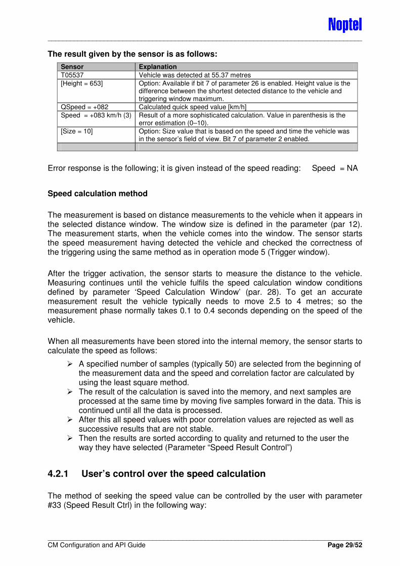
The result given by the sensor is as follows:
Sensor Explanation
T05537 Vehicle was detected at 55.37 metres
[Height = 653] Option: Available if bit 7 of parameter 26 is enabled. Height value is the difference between the shortest detected distance to the vehicle and triggering window maximum.
QSpeed = +082 Calculated quick speed value [km/h]
Speed = +083 km/h (3) Result of a more sophisticated calculation. Value in parenthesis is the error estimation (0–10).
[Size = 10] Option: Size value that is based on the speed and time the vehicle was in the sensor’s field of view. Bit 7 of parameter 2 enabled.
Error response is the following; it is given instead of the speed reading: Speed = NA
Speed calculation method
The measurement is based on distance measurements to the vehicle when it appears in the selected distance window. The window size is defined in the parameter (par 12). The measurement starts, when the vehicle comes into the window. The sensor starts the speed measurement having detected the vehicle and checked the correctness of the triggering using the same method as in operation mode 5 (Trigger window).
After the trigger activation, the sensor starts to measure the distance to the vehicle. Measuring continues until the vehicle fulfils the speed calculation window conditions defined by parameter ‘Speed Calculation Window’ (par. 28). To get an accurate measurement result the vehicle typically needs to move 2.5 to 4 metres; so the measurement phase normally takes 0.1 to 0.4 seconds depending on the speed of the vehicle.
When all measurements have been stored into the internal memory, the sensor starts to calculate the speed as follows:
� A specified number of samples (typically 50) are selected from the beginning of the measurement data and the speed and correlation factor are calculated by using the least square method.
� The result of the calculation is saved into the memory, and next samples are processed at the same time by moving five samples forward in the data. This is continued until all the data is processed.
� After this all speed values with poor correlation values are rejected as well as successive results that are not stable.
� Then the results are sorted according to quality and returned to the user the way they have selected (Parameter “Speed Result Control”)
4.2.1 User’s control over the speed calculation
The method of seeking the speed value can be controlled by the user with parameter #33 (Speed Result Ctrl) in the following way:

____________________________________________________________________________________
____________________________________________________________________________________ CM Configuration and API Guide Page 30/52
Setting Method
0 The sensor prefers slower speed components of the data and does not give faulty speed readings that are too high. This setting also prevents speed measurement if the measured data is not stable.
1 This prefers speed values that exist in the majority of the measurement data. In the case of several speed components, it uses the average and will also give data in more difficult cases. Typically this setting works well when measuring departing vehicles.
2 The sensor will indicate “NA” (Not Available) if there is too much variation in the data about speed components.
3 The sensor indicates an average of all stable enough speed components. This setting is suitable for statistical data collecting as it typically does not give many NA’s.
4 This setting is designed to be used for approaching vehicles and especially when the sensor is mounted above the road and distance to the vehicle is less than 30 metres (works also with >30 m). It prefers higher speed components.
4.2.2 Adaptive measurement window for departing vehicles
The sensor includes a possibility to move the measurement window up when a large/tall vehicle is detected. This function helps to get valid measurement data also from higher vehicles. Fig. 7 illustrates the movement of the window and how the parameters affect.
Notice that even though the measurement window is moved, the triggering is still given at the same distance. The moved window only has an effect on the distance of data collecting for the speed calculation.
Fig. 7. Adaptive measurement window for departing vehicles
Parameters for Adaptive measurement window function are following:
No. Type Name / Description Unit Range Default
1 B Operation Mode 7
2 B Control Byte 1
b5 Speed Behind 1
39,40 W Vehicle Height Limit cm 200 - 1000
41,42 W Window Move For Big Vehicles cm
Sensor (CMP3/52)
Triggering distance
Par 14
Par 39
Moved window
Par 41
Driving direction
Actual Vehicle height limit
h
Normal window
Par 12
Normal data collecting area
Data collecting area for high vehicles
Par 32 H
C
Height movement of new data collection point
h1

____________________________________________________________________________________
____________________________________________________________________________________ CM Configuration and API Guide Page 31/52
Calculation of the adaptive window parameters 39 and 41:
The corresponding sides of similar triangles have lengths that are in the same proportion. This leads to following equations (see Fig. 7):
H
ChPar
Par
h
C
H
⋅
=⇒
=
39
39
H
ChPar
Par
h
C
H
⋅
=⇒
=
1
1
41
41
By using dimensions in [cm] the values of parameters will have right unit.
Setting of the parameter 39 enables a possibility to have a different measurement window for larger (higher) vehicles. This function is active in the speed measurement of departing vehicles (mode 7).
In this case the height value is the difference between the shortest measured value from the vehicle and the far end of the triggering window. For example, in a set-up where the sensor locates 6 metres above the road and the maximum distance to vehicles is 30 metres, a 2-metre height limit means a value of 1000 cm. But as the measurement window does not reach the surface of the road, typically a value of approximately 750 is used.
The user may check the actual height values of different vehicles by enabling ‘Height’ measurement by bit 7 of parameter 26 and making some test speed measurements. The size of measurement window movement is defined by the next parameter.
The parameter 41 defines how much the triggering window is moved for large vehicles. In the setup described with previous parameter values, 200 cm changes the height of the measurement window by 40 cm. The value of 200 to 250 cm has typically been accurate.
4.2.3 Automatic distance setting of measurement window
The sensor includes a function that helps the user to set up the triggering window at a correct distance. The function is designed to be used with Speed measurement mode (7), but can also be used to set up Trigger window mode (5).
Calibration can be done both for approaching and departing vehicles. For approaching vehicles bit 5 of Control Byte 1 (par. 2) must be cleared. Calibration is started with command “U”. If calibration is used to set up speed measurement with one sensor, it is recommended to use a 5-m window size or even bigger if target can be tracked during a longer distance (this depends on the measurement geometry). Otherwise the user may define the size of the window best suited for their application.
To calibrate the window for departing vehicles bit 5 of Control Byte 2 (Speed Behind) must be set. This method is designed to be used to set up a ‘single sensor speed
____________________________________________________________________________________
____________________________________________________________________________________ CM Configuration and API Guide Page 32/52
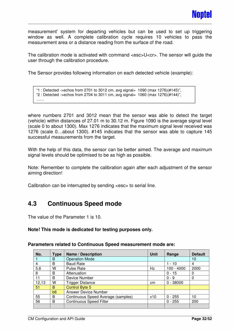
measurement’ system for departing vehicles but can be used to set up triggering window as well. A complete calibration cycle requires 10 vehicles to pass the measurement area or a distance reading from the surface of the road.
The calibration mode is activated with command <esc>U<cr>. The sensor will guide the user through the calibration procedure.
The Sensor provides following information on each detected vehicle (example):
where numbers 2701 and 3012 mean that the sensor was able to detect the target (vehicle) within distances of 27.01 m to 30.12 m. Figure 1090 is the average signal level (scale 0 to about 1300). Max 1276 indicates that the maximum signal level received was 1276 (scale 0…about 1300). #145 indicates that the sensor was able to capture 145 successful measurements from the target.
With the help of this data, the sensor can be better aimed. The average and maximum signal levels should be optimised to be as high as possible.
Note: Remember to complete the calibration again after each adjustment of the sensor aiming direction!
Calibration can be interrupted by sending <esc> to serial line.
4.3 Continuous Speed mode
The value of the Parameter 1 is 10.
Note! This mode is dedicated for testing purposes only.
Parameters related to Continuous Speed measurement mode are:
No. Type Name / Description Unit Range Default
1 B Operation Mode 10
4 B Baud Rate 1 - 10 4
5,6 W Pulse Rate Hz 100 - 4000 2000
8 B Attenuation 0 - 15 0
11 B Device Number 0 - 9 0
12,13 W Trigger Distance cm 0 - 38000
51 B Control Byte 5
b6 Answer Device Number
55 B Continuous Speed Average (samples) x10 0 - 255 10
56 B Continuous Speed Filter 0 - 255 200
“1 : Detected ->echos from 2701 to 3012 cm, avg signal= 1090 (max 1276)(#145)”, “2 : Detected ->echos from 2704 to 3011 cm, avg signal= 1060 (max 1276)(#144)”, ……
____________________________________________________________________________________
____________________________________________________________________________________ CM Configuration and API Guide Page 33/52
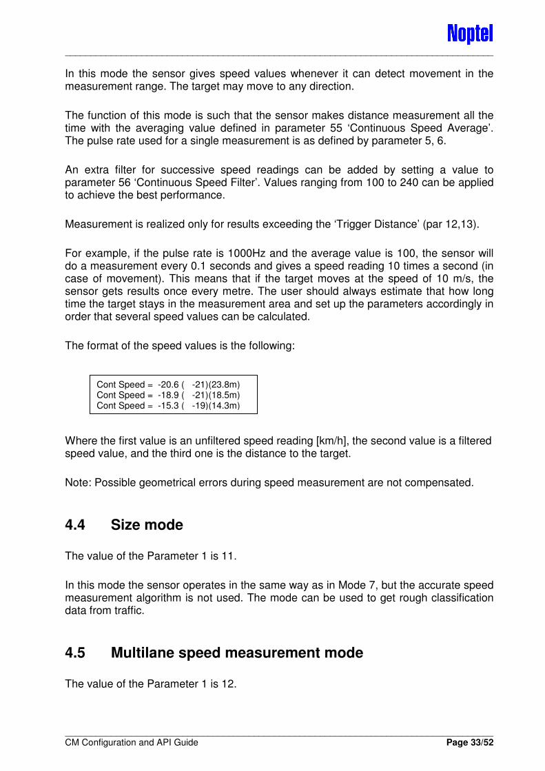
In this mode the sensor gives speed values whenever it can detect movement in the measurement range. The target may move to any direction.
The function of this mode is such that the sensor makes distance measurement all the time with the averaging value defined in parameter 55 ‘Continuous Speed Average’. The pulse rate used for a single measurement is as defined by parameter 5, 6.
An extra filter for successive speed readings can be added by setting a value to parameter 56 ‘Continuous Speed Filter’. Values ranging from 100 to 240 can be applied to achieve the best performance.
Measurement is realized only for results exceeding the ‘Trigger Distance’ (par 12,13).
For example, if the pulse rate is 1000Hz and the average value is 100, the sensor will do a measurement every 0.1 seconds and gives a speed reading 10 times a second (in case of movement). This means that if the target moves at the speed of 10 m/s, the sensor gets results once every metre. The user should always estimate that how long time the target stays in the measurement area and set up the parameters accordingly in order that several speed values can be calculated.
The format of the speed values is the following:
Where the first value is an unfiltered speed reading [km/h], the second value is a filtered speed value, and the third one is the distance to the target.
Note: Possible geometrical errors during speed measurement are not compensated.
4.4 Size mode
The value of the Parameter 1 is 11.
In this mode the sensor operates in the same way as in Mode 7, but the accurate speed measurement algorithm is not used. The mode can be used to get rough classification data from traffic.
4.5 Multilane speed measurement mode
The value of the Parameter 1 is 12.
Cont Speed = -20.6 ( -21)(23.8m) Cont Speed = -18.9 ( -21)(18.5m) Cont Speed = -15.3 ( -19)(14.3m)
____________________________________________________________________________________
____________________________________________________________________________________ CM Configuration and API Guide Page 34/52
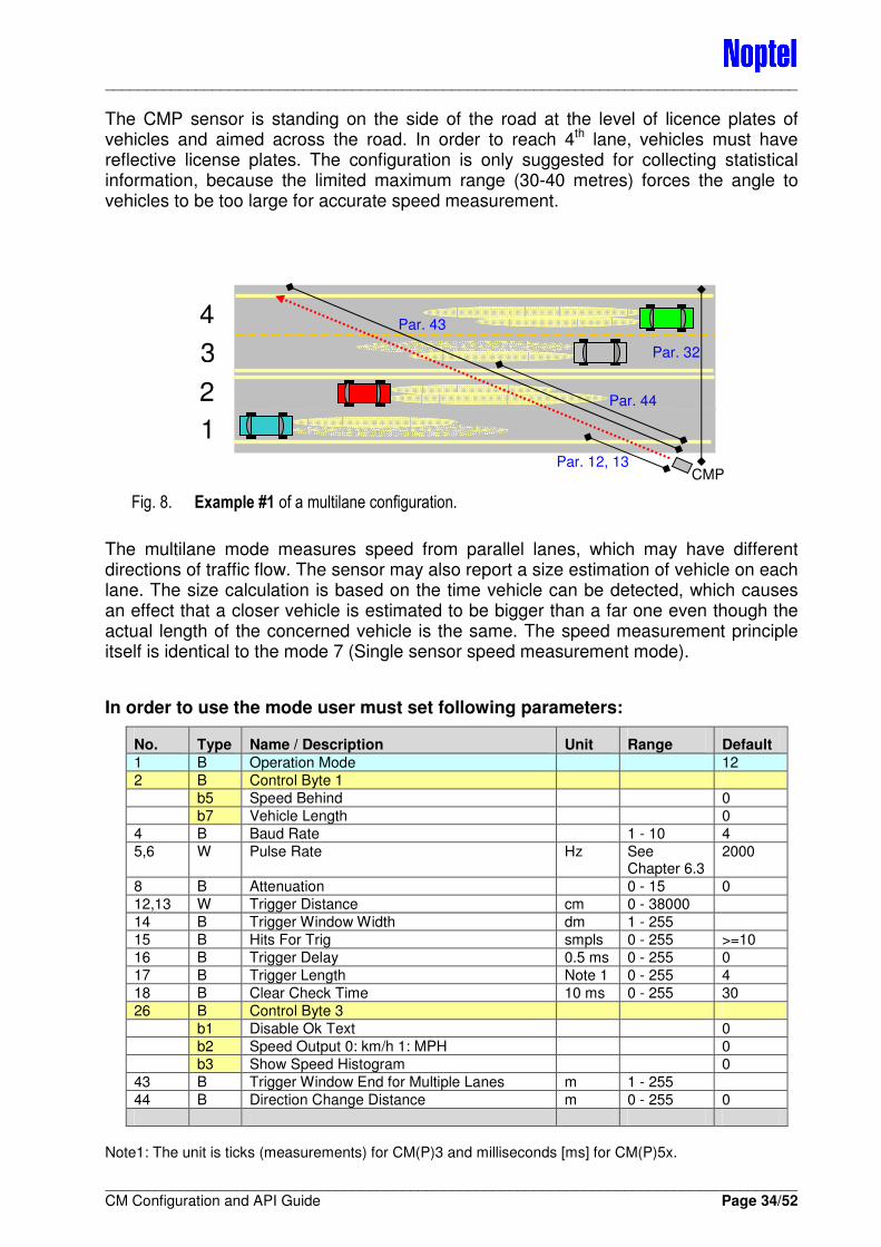
The CMP sensor is standing on the side of the road at the level of licence plates of vehicles and aimed across the road. In order to reach 4th lane, vehicles must have reflective license plates. The configuration is only suggested for collecting statistical information, because the limited maximum range (30-40 metres) forces the angle to vehicles to be too large for accurate speed measurement.
Fig. 8. Example #1 of a multilane configuration.
The multilane mode measures speed from parallel lanes, which may have different directions of traffic flow. The sensor may also report a size estimation of vehicle on each lane. The size calculation is based on the time vehicle can be detected, which causes an effect that a closer vehicle is estimated to be bigger than a far one even though the actual length of the concerned vehicle is the same. The speed measurement principle itself is identical to the mode 7 (Single sensor speed measurement mode).
In order to use the mode user must set following parameters:
No. Type Name / Description Unit Range Default
1 B Operation Mode 12
2 B Control Byte 1
b5 Speed Behind 0
b7 Vehicle Length 0
4 B Baud Rate 1 - 10 4
5,6 W Pulse Rate Hz See Chapter 6.3
2000
8 B Attenuation 0 - 15 0
12,13 W Trigger Distance cm 0 - 38000
14 B Trigger Window Width dm 1 - 255
15 B Hits For Trig smpls 0 - 255 >=10
16 B Trigger Delay 0.5 ms 0 - 255 0
17 B Trigger Length Note 1 0 - 255 4
18 B Clear Check Time 10 ms 0 - 255 30
26 B Control Byte 3
b1 Disable Ok Text 0
b2 Speed Output 0: km/h 1: MPH 0
b3 Show Speed Histogram 0
43 B Trigger Window End for Multiple Lanes m 1 - 255
44 B Direction Change Distance m 0 - 255 0
Note1: The unit is ticks (measurements) for CM(P)3 and milliseconds [ms] for CM(P)5x.
CMP
Par. 32
Par. 44
Par. 12, 13
1
2
3
4 Par. 43
____________________________________________________________________________________
____________________________________________________________________________________ CM Configuration and API Guide Page 35/52
Speed parameters for the road side operation:
No. Type Name / Description Unit Range Default
28 B Speed Calculation Window dm 40 - 50 40
29,30 W Speed Pulse Rate Hz See Chapter 6.3
2000
31 B Speed Calculation Start dm 2 - 10 10
32 B Speed Geometry dm
33 B Speed Result Ctrl (see next paragraphs) 0 - 4
34 B Separation limit 0.1 s 0 - 255 0
35 B Speed Filter Length (35 + value x 5) 0 - 10 5
37 B Speed Limit km/h
38 B Speed Accept Limit (behind 2, front 5) 0 - 10
Following information may be added to the result:
No. Type Name / Description Unit Range Default
50 B Control Byte 4
b0 Trigger Time Output 0
b1 Trigger Time Interval 0
b2 Trigger Occupancy Time 0
b4 Count Output 0
51 B Control Byte 5
b0 Separation between vehicles 0
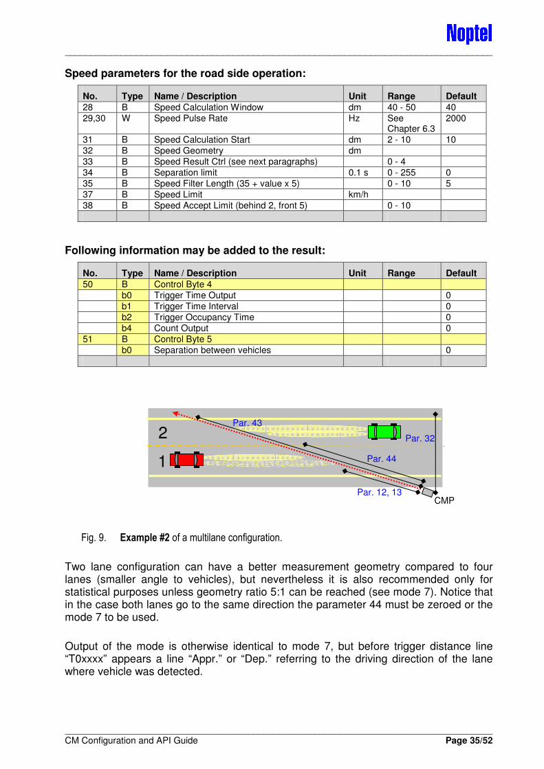
Fig. 9. Example #2 of a multilane configuration.
Two lane configuration can have a better measurement geometry compared to four lanes (smaller angle to vehicles), but nevertheless it is also recommended only for statistical purposes unless geometry ratio 5:1 can be reached (see mode 7). Notice that in the case both lanes go to the same direction the parameter 44 must be zeroed or the mode 7 to be used.
Output of the mode is otherwise identical to mode 7, but before trigger distance line “T0xxxx” appears a line “Appr.” or “Dep.” referring to the driving direction of the lane where vehicle was detected.
1
2
CMP
Par. 44
Par. 43
Par. 12, 13
Par. 32
____________________________________________________________________________________
____________________________________________________________________________________ CM Configuration and API Guide Page 36/52
5 DETECTION MODES
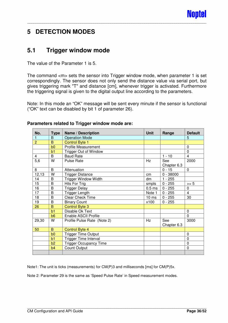
5.1 Trigger window mode
The value of the Parameter 1 is 5.
The command <m> sets the sensor into Trigger window mode, when parameter 1 is set correspondingly. The sensor does not only send the distance value via serial port, but gives triggering mark "T" and distance [cm], whenever trigger is activated. Furthermore the triggering signal is given to the digital output line according to the parameters.
Note: In this mode an “OK” message will be sent every minute if the sensor is functional (“OK” text can be disabled by bit 1 of parameter 26).
Parameters related to Trigger window mode are:
No. Type Name / Description Unit Range Default
1 B Operation Mode 5
2 B Control Byte 1
b0 Profile Measurement 0
b1 Trigger Out of Window 0
4 B Baud Rate 1 - 10 4
5,6 W Pulse Rate Hz See Chapter 6.3
2000
8 B Attenuation 0 - 15 0
12,13 W Trigger Distance cm 0 - 38000
14 B Trigger Window Width dm 1 - 255
15 B Hits For Trig smpls 0 - 255 >= 5
16 B Trigger Delay 0.5 ms 0 - 255 0
17 B Trigger Length Note 1 0 - 255 4
18 B Clear Check Time 10 ms 0 - 255 30
19 B Binary Count x100 0 - 255
26 B Control Byte 3
b1 Disable Ok Text 0
b6 Enable ASCII Profile 0
29,30 W Profile Pulse Rate (Note 2) Hz See Chapter 6.3
3000
50 B Control Byte 4
b0 Trigger Time Output 0
b1 Trigger Time Interval 0
b2 Trigger Occupancy Time 0
b4 Count Output 0
Note1: The unit is ticks (measurements) for CM(P)3 and milliseconds [ms] for CM(P)5x. Note 2: Parameter 29 is the same as ‘Speed Pulse Rate’ in Speed measurement modes.
____________________________________________________________________________________
____________________________________________________________________________________ CM Configuration and API Guide Page 37/52
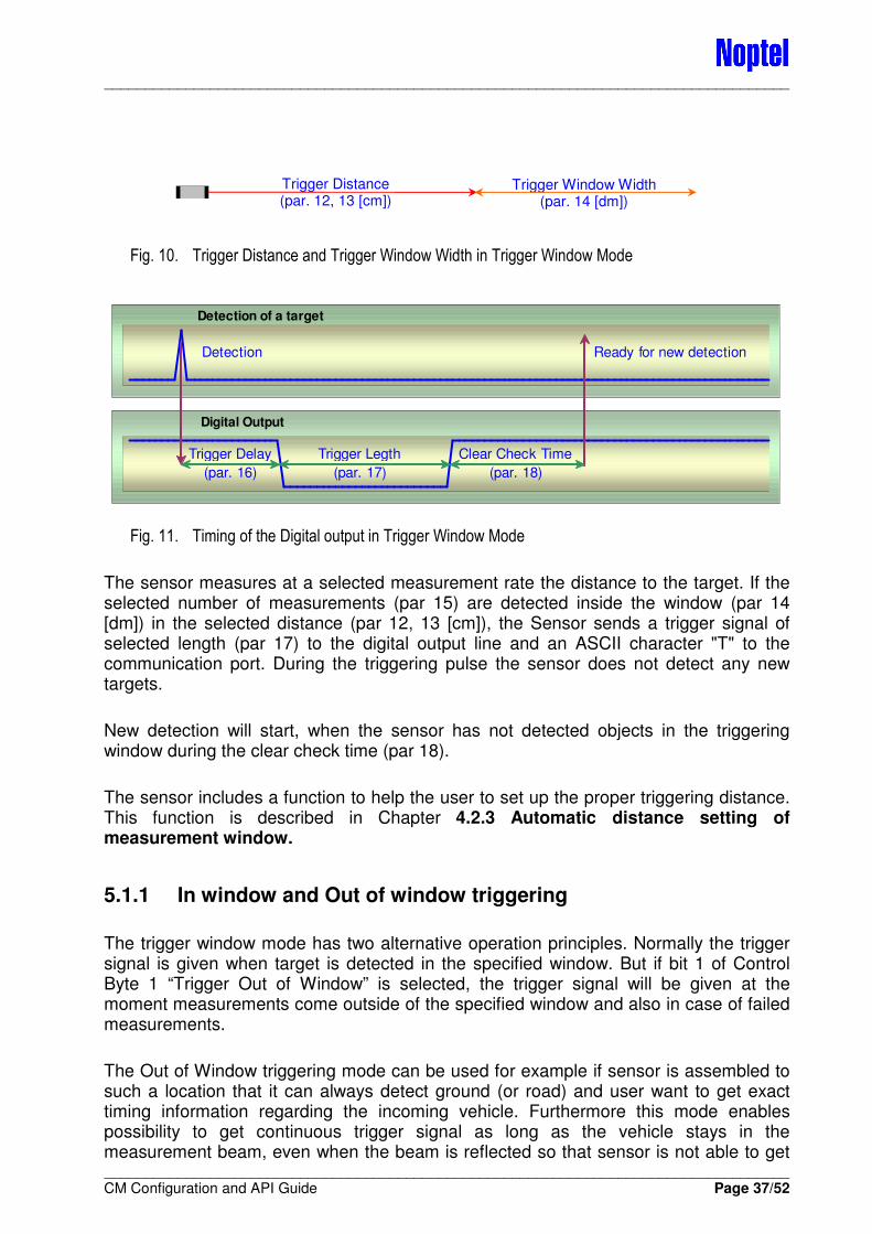
Fig. 10. Trigger Distance and Trigger Window Width in Trigger Window Mode
Fig. 11. Timing of the Digital output in Trigger Window Mode
The sensor measures at a selected measurement rate the distance to the target. If the selected number of measurements (par 15) are detected inside the window (par 14 [dm]) in the selected distance (par 12, 13 [cm]), the Sensor sends a trigger signal of selected length (par 17) to the digital output line and an ASCII character "T" to the communication port. During the triggering pulse the sensor does not detect any new targets.
New detection will start, when the sensor has not detected objects in the triggering window during the clear check time (par 18).
The sensor includes a function to help the user to set up the proper triggering distance. This function is described in Chapter 4.2.3 Automatic distance setting of measurement window.
5.1.1 In window and Out of window triggering
The trigger window mode has two alternative operation principles. Normally the trigger signal is given when target is detected in the specified window. But if bit 1 of Control Byte 1 “Trigger Out of Window” is selected, the trigger signal will be given at the moment measurements come outside of the specified window and also in case of failed measurements.
The Out of Window triggering mode can be used for example if sensor is assembled to such a location that it can always detect ground (or road) and user want to get exact timing information regarding the incoming vehicle. Furthermore this mode enables possibility to get continuous trigger signal as long as the vehicle stays in the measurement beam, even when the beam is reflected so that sensor is not able to get
Trigger Distance (par. 12, 13 [cm])
Trigger Window Width (par. 14 [dm])
Digital Output
Trigger Delay
(par. 16)
Trigger Legth
(par. 17)
Clear Check Time
(par. 18)
Detection of a target
Detection Ready for new detection
____________________________________________________________________________________
____________________________________________________________________________________ CM Configuration and API Guide Page 38/52
distance measurements from the vehicle (In this case set identical value to parameters #15 “Hits For Trig” and #17 “Trigger Length”. Also set zero to parameter #18 “Clear Check Time”.)
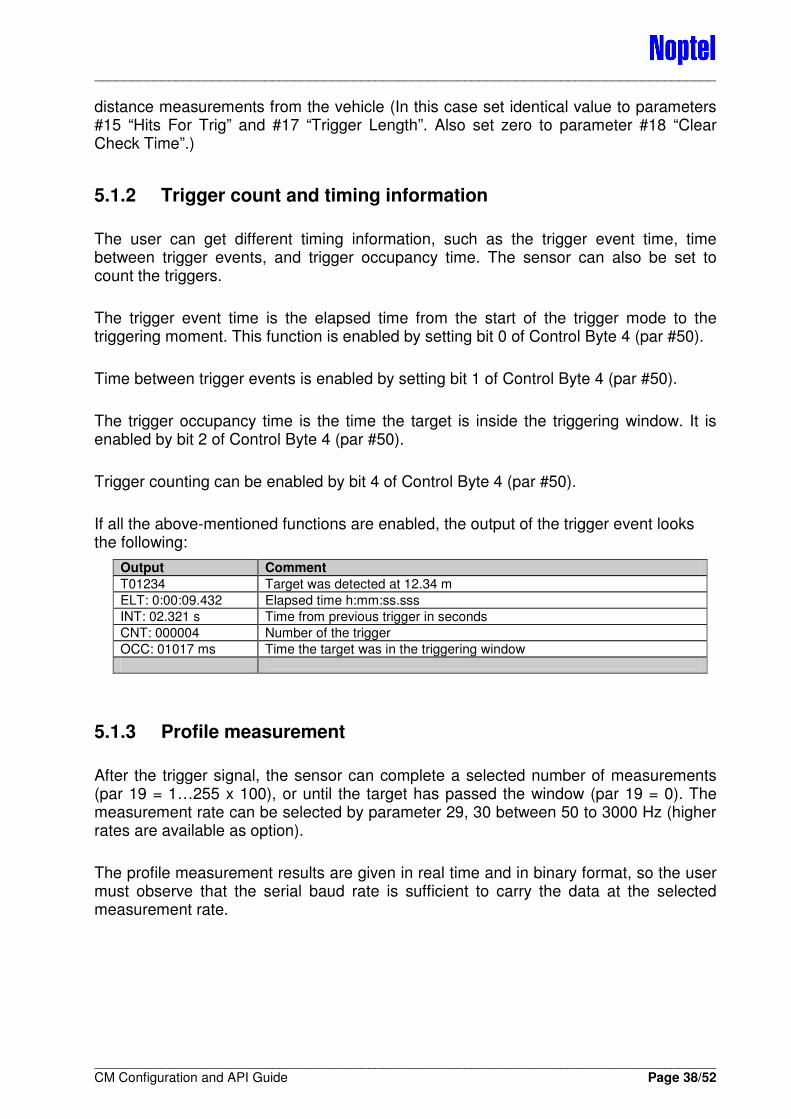
5.1.2 Trigger count and timing information
The user can get different timing information, such as the trigger event time, time between trigger events, and trigger occupancy time. The sensor can also be set to count the triggers.
The trigger event time is the elapsed time from the start of the trigger mode to the triggering moment. This function is enabled by setting bit 0 of Control Byte 4 (par #50).
Time between trigger events is enabled by setting bit 1 of Control Byte 4 (par #50).
The trigger occupancy time is the time the target is inside the triggering window. It is enabled by bit 2 of Control Byte 4 (par #50).
Trigger counting can be enabled by bit 4 of Control Byte 4 (par #50).
If all the above-mentioned functions are enabled, the output of the trigger event looks the following:
Output Comment
T01234 Target was detected at 12.34 m
ELT: 0:00:09.432 Elapsed time h:mm:ss.sss
INT: 02.321 s Time from previous trigger in seconds
CNT: 000004 Number of the trigger
OCC: 01017 ms Time the target was in the triggering window
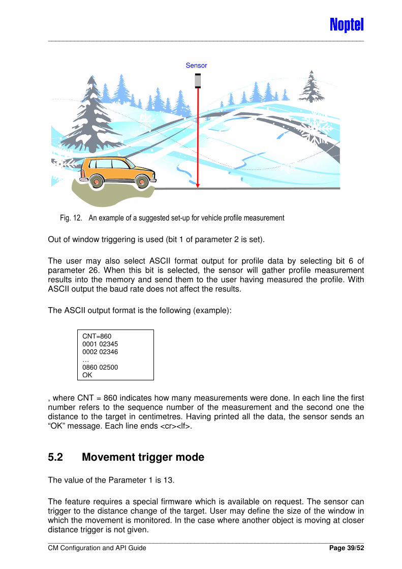
5.1.3 Profile measurement
After the trigger signal, the sensor can complete a selected number of measurements (par 19 = 1…255 x 100), or until the target has passed the window (par 19 = 0). The measurement rate can be selected by parameter 29, 30 between 50 to 3000 Hz (higher rates are available as option).
The profile measurement results are given in real time and in binary format, so the user must observe that the serial baud rate is sufficient to carry the data at the selected measurement rate.
____________________________________________________________________________________
____________________________________________________________________________________ CM Configuration and API Guide Page 39/52
Fig. 12. An example of a suggested set-up for vehicle profile measurement
Out of window triggering is used (bit 1 of parameter 2 is set).
The user may also select ASCII format output for profile data by selecting bit 6 of parameter 26. When this bit is selected, the sensor will gather profile measurement results into the memory and send them to the user having measured the profile. With ASCII output the baud rate does not affect the results.
The ASCII output format is the following (example):
, where CNT = 860 indicates how many measurements were done. In each line the first number refers to the sequence number of the measurement and the second one the distance to the target in centimetres. Having printed all the data, the sensor sends an “OK” message. Each line ends <cr><lf>.
5.2 Movement trigger mode
The value of the Parameter 1 is 13.
The feature requires a special firmware which is available on request. The sensor can trigger to the distance change of the target. User may define the size of the window in which the movement is monitored. In the case where another object is moving at closer distance trigger is not given.
Sensor
CNT=860 0001 02345 0002 02346 … 0860 02500 OK
____________________________________________________________________________________
____________________________________________________________________________________ CM Configuration and API Guide Page 40/52
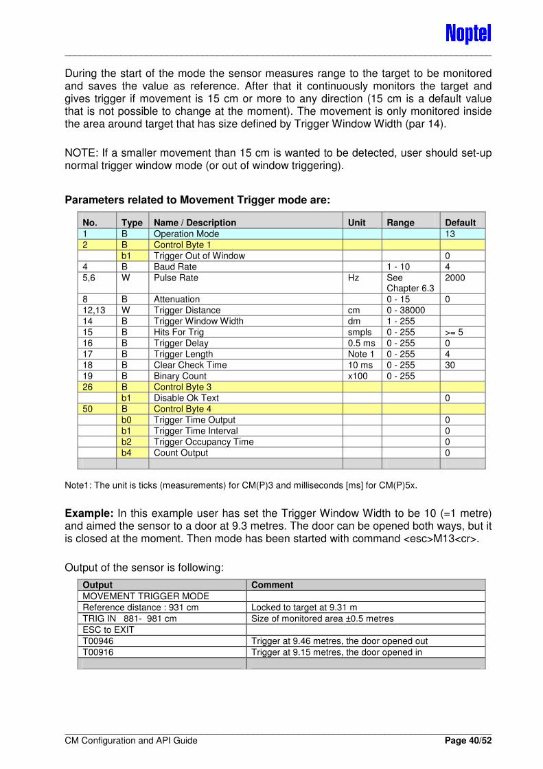
During the start of the mode the sensor measures range to the target to be monitored and saves the value as reference. After that it continuously monitors the target and gives trigger if movement is 15 cm or more to any direction (15 cm is a default value that is not possible to change at the moment). The movement is only monitored inside the area around target that has size defined by Trigger Window Width (par 14).
NOTE: If a smaller movement than 15 cm is wanted to be detected, user should set-up normal trigger window mode (or out of window triggering).
Parameters related to Movement Trigger mode are:
No. Type Name / Description Unit Range Default
1 B Operation Mode 13
2 B Control Byte 1
b1 Trigger Out of Window 0
4 B Baud Rate 1 - 10 4
5,6 W Pulse Rate Hz See Chapter 6.3
2000
8 B Attenuation 0 - 15 0
12,13 W Trigger Distance cm 0 - 38000
14 B Trigger Window Width dm 1 - 255
15 B Hits For Trig smpls 0 - 255 >= 5
16 B Trigger Delay 0.5 ms 0 - 255 0
17 B Trigger Length Note 1 0 - 255 4
18 B Clear Check Time 10 ms 0 - 255 30
19 B Binary Count x100 0 - 255
26 B Control Byte 3
b1 Disable Ok Text 0
50 B Control Byte 4
b0 Trigger Time Output 0
b1 Trigger Time Interval 0
b2 Trigger Occupancy Time 0
b4 Count Output 0
Note1: The unit is ticks (measurements) for CM(P)3 and milliseconds [ms] for CM(P)5x.
Example: In this example user has set the Trigger Window Width to be 10 (=1 metre) and aimed the sensor to a door at 9.3 metres. The door can be opened both ways, but it is closed at the moment. Then mode has been started with command <esc>M13<cr>.
Output of the sensor is following:
Output Comment
MOVEMENT TRIGGER MODE
Reference distance : 931 cm Locked to target at 9.31 m
TRIG IN 881- 981 cm Size of monitored area ±0.5 metres
ESC to EXIT
T00946 Trigger at 9.46 metres, the door opened out
T00916 Trigger at 9.15 metres, the door opened in
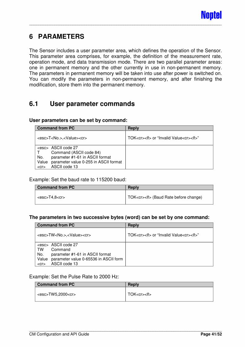
____________________________________________________________________________________
____________________________________________________________________________________ CM Configuration and API Guide Page 41/52
6 PARAMETERS
The Sensor includes a user parameter area, which defines the operation of the Sensor. This parameter area comprises, for example, the definition of the measurement rate, operation mode, and data transmission mode. There are two parallel parameter areas: one in permanent memory and the other currently in use in non-permanent memory. The parameters in permanent memory will be taken into use after power is switched on. You can modify the parameters in non-permanent memory, and after finishing the modification, store them into the permanent memory.
6.1 User parameter commands
User parameters can be set by command:
Command from PC Reply
<esc>T<No.>,<Value><cr>
TOK<cr><lf> or “Invalid Value<cr><lf>”
<esc> ASCII code 27 T Command (ASCII code 84) No. parameter #1-61 in ASCII format Value parameter value 0-255 in ASCII format <cr> ASCII code 13
Example: Set the baud rate to 115200 baud:
Command from PC Reply
<esc>T4,8<cr>
TOK<cr><lf> (Baud Rate before change)
The parameters in two successive bytes (word) can be set by one command:
Command from PC Reply
<esc>TW<No.>,<Value><cr>
TOK<cr><lf> or “Invalid Value<cr><lf>”
<esc> ASCII code 27 TW Command No. parameter #1-61 in ASCII format Value parameter value 0-65536 in ASCII form <cr> ASCII code 13
Example: Set the Pulse Rate to 2000 Hz:
Command from PC Reply
<esc>TW5,2000<cr>
TOK<cr><lf>

____________________________________________________________________________________
____________________________________________________________________________________ CM Configuration and API Guide Page 42/52
User parameters can be read by command:
Command from PC Reply
<esc>L<No.><cr>
L00xxx<cr><lf>
<esc> ASCII code 27 L Command (ASCII code 76) No. parameter #1-61 in ASCII format <cr> ASCII code 13
xxx Value of parameter
Example: Read the parameter 19:
Command from PC Reply
<esc>L19<cr>
L00060<cr><lf>
The parameters in two successive bytes (word) can be read by one command:
Command from PC Reply
<esc>LW<No.><cr>
L00xxx<cr><lf>
<esc> ASCII code 27 LW Command No. parameter #1-61 in ASCII format <cr> ASCII code 13
xxx Value of parameter
Example: Read the Word parameter 5:
Command from PC Reply
<esc>LW5<cr>
L02000<cr><lf>
All available user parameters can be read by command:
Command from PC Reply
<esc>L<cr>
L0001 00xxx<cr><lf> L0002 00xxx<cr><lf> L0003 00xxx<cr><lf> …
<esc> ASCII code 27 L Command (ASCII code 76) <cr> ASCII code 13
xxx Values of parameters

____________________________________________________________________________________
____________________________________________________________________________________ CM Configuration and API Guide Page 43/52
6.2 Permanent memory parameters
Writing parameters into the permanent memory requires special attention.
Permanent memory parameters are protected by a special lock that has to be opened before changing the parameters. The parameter area is also protected by checksum calculation. If the checksum is wrong, the sensor does not perform measurements. Having transferred the user parameters into permanent memory, the sensor automatically calculates the checksum.
To enable the permanent memory for writing:
Command from PC Reply
<esc>X<cr> (X, ASCII-code 88, h58)
WR ENABLE<cr><lf>
Parameters are set into the permanent memory by command:
Command from PC Reply
<esc>S<cr> (S, ASCII-code 83, h53)
SOK<cr><lf>
Parameters can be read from permanent memory by command:
Command from PC Reply
<esc>P<No.><cr>
P00xxx<cr><lf>
<esc> ASCII code 27 P Command (ASCII code 80) No. parameter #1-61 in ASCII format <cr> ASCII code 13
xxx Value of parameter
6.3 Parameter list
The sensor provides three types of parameters. In binary format each bit in the parameter carries meaning. In byte (8 bit) and word (16 bit) formats the parameter is able to receive values from 0 to 255 and from 0 to 65536 respectively.
In the following descriptions these parameters are marked as:
� B = Byte (8 bits) � W = Word (2 bytes)
Note: All parameters are not valid for all software versions.
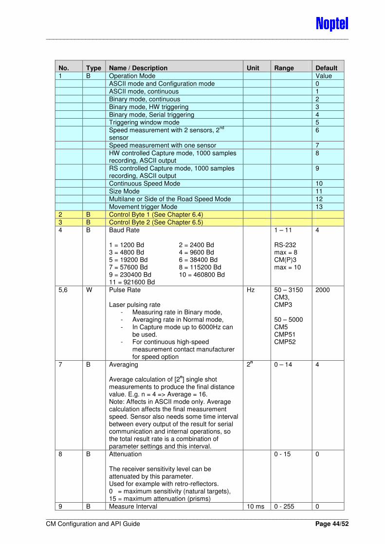
____________________________________________________________________________________
____________________________________________________________________________________ CM Configuration and API Guide Page 44/52
No. Type Name / Description Unit Range Default
1 B Operation Mode Value
ASCII mode and Configuration mode 0
ASCII mode, continuous 1
Binary mode, continuous 2
Binary mode, HW triggering 3
Binary mode, Serial triggering 4 Triggering window mode 5
Speed measurement with 2 sensors, 2nd
sensor
6
Speed measurement with one sensor 7
HW controlled Capture mode, 1000 samples recording, ASCII output
8
RS controlled Capture mode, 1000 samples recording, ASCII output
9
Continuous Speed Mode 10
Size Mode 11
Multilane or Side of the Road Speed Mode 12
Movement trigger Mode 13
2 B Control Byte 1 (See Chapter 6.4)
3 B Control Byte 2 (See Chapter 6.5)
4 B Baud Rate 1 = 1200 Bd 2 = 2400 Bd 3 = 4800 Bd 4 = 9600 Bd 5 = 19200 Bd 6 = 38400 Bd 7 = 57600 Bd 8 = 115200 Bd 9 = 230400 Bd 10 = 460800 Bd 11 = 921600 Bd
1 – 11 RS-232 max = 8 CM(P)3 max = 10
4
5,6 W Pulse Rate Laser pulsing rate
- Measuring rate in Binary mode, - Averaging rate in Normal mode, - In Capture mode up to 6000Hz can
be used. - For continuous high-speed
measurement contact manufacturer for speed option
Hz 50 – 3150 CM3, CMP3 50 – 5000 CM5 CMP51 CMP52
2000
7 B Averaging Average calculation of [2
n] single shot
measurements to produce the final distance value. E.g. n = 4 => Average = 16. Note: Affects in ASCII mode only. Average calculation affects the final measurement speed. Sensor also needs some time interval between every output of the result for serial communication and internal operations, so the total result rate is a combination of parameter settings and this interval.
2n 0 – 14 4
8 B Attenuation The receiver sensitivity level can be attenuated by this parameter. Used for example with retro-reflectors. 0 = maximum sensitivity (natural targets), 15 = maximum attenuation (prisms)
0 - 15 0
9 B Measure Interval 10 ms 0 - 255 0
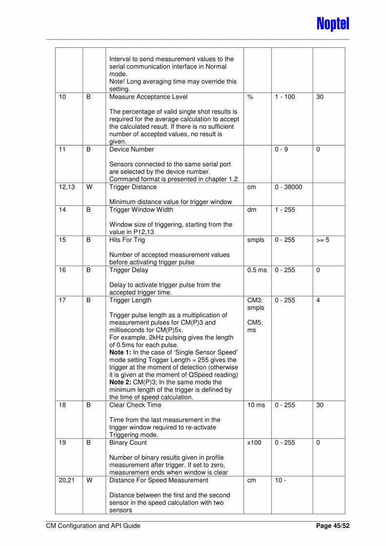
____________________________________________________________________________________
____________________________________________________________________________________ CM Configuration and API Guide Page 45/52
Interval to send measurement values to the serial communication interface in Normal mode. Note! Long averaging time may override this setting.
10 B Measure Acceptance Level The percentage of valid single shot results is required for the average calculation to accept the calculated result. If there is no sufficient number of accepted values, no result is given.
% 1 - 100 30
11 B Device Number Sensors connected to the same serial port are selected by the device number. Command format is presented in chapter 1.2.
0 - 9 0
12,13 W Trigger Distance Minimum distance value for trigger window
cm 0 - 38000
14 B Trigger Window Width Window size of triggering, starting from the value in P12,13
dm 1 - 255
15 B Hits For Trig Number of accepted measurement values before activating trigger pulse
smpls 0 - 255 >= 5
16 B Trigger Delay Delay to activate trigger pulse from the accepted trigger time.
0.5 ms 0 - 255 0
17 B Trigger Length Trigger pulse length as a multiplication of measurement pulses for CM(P)3 and milliseconds for CM(P)5x. For example, 2kHz pulsing gives the length of 0.5ms for each pulse. Note 1: In the case of ‘Single Sensor Speed’ mode setting Trigger Length = 255 gives the trigger at the moment of detection (otherwise it is given at the moment of QSpeed reading) Note 2: CM(P)3; In the same mode the minimum length of the trigger is defined by the time of speed calculation.
CM3: smpls CM5: ms
0 - 255 4
18 B Clear Check Time Time from the last measurement in the trigger window required to re-activate Triggering mode.
10 ms 0 - 255 30
19 B Binary Count Number of binary results given in profile measurement after trigger. If set to zero, measurement ends when window is clear
x100 0 - 255 0
20,21 W Distance For Speed Measurement Distance between the first and the second sensor in the speed calculation with two sensors
cm 10 -

____________________________________________________________________________________
____________________________________________________________________________________ CM Configuration and API Guide Page 46/52
22 B Binary Average Parameter is used only if ‘Millimetre output’ of Control Byte 2 is enabled.
2n 0 - 14 0
23 B Analogue Output Offset Starting point for analogue signal.
m 0 - 255 0
24 B Analogue Output Scale Scale of the analogue signal (12 bit, 4096), giving the signal accuracy and (measurement range) 1 = 1mm (Range = 4m), 10 = 1cm (Range = 40m), 100 = 10cm (Range = 400m)
mm 0 - 255 0
25 B Continuous Filter This parameter is used with continuous measurement function in ASCII mode initiated by command ‘C’ or in mode 1. Filter operates so that the new distance value is always calculated partly from the previous one. The fraction of the ‘old’ result used to calculate the new result is defined by this parameter divided by 256.
0 - 255 0
26 B Control Byte 3 (See Chapter 6.6)
27 B Zeroing Control of Analogue Output 0 = failed measurement sets analogue output to zero. 1 = Analogue output is never set to zero. 2 - 17 = Analogue output is set to zero after 1, 2, 4, 8, 16, ..., 32768 measurements
0 - 17 0
28 B Speed Calculation Window Window width used in speed calculation. Typically value 20–25 dm (2–2.5m) Note: Trigger window (par 14) must be larger than this. Typically a 5-metre triggering window is used in Speed measurement mode with one sensor.
dm 20 - 40 20
29,30 W Speed Pulse Rate This measurement frequency is used during speed acquisition. Note! The same parameter will define the profile measurement rate.
Hz 50 – 3150 CM3, CMP3 50 – 5000 CM5 CMP51 CMP52
3000
31 B Speed Calculation Start The starting point of speed calculation: This parameter defines how long a distance from the triggering point is rejected in speed calculation.
dm 2 - 10
32 B Speed Geometry Dimensional offset of the sensor from the line of movement of the measured object E.g. height of the Sensor above the road surface, 55 dm
dm 0 - 255
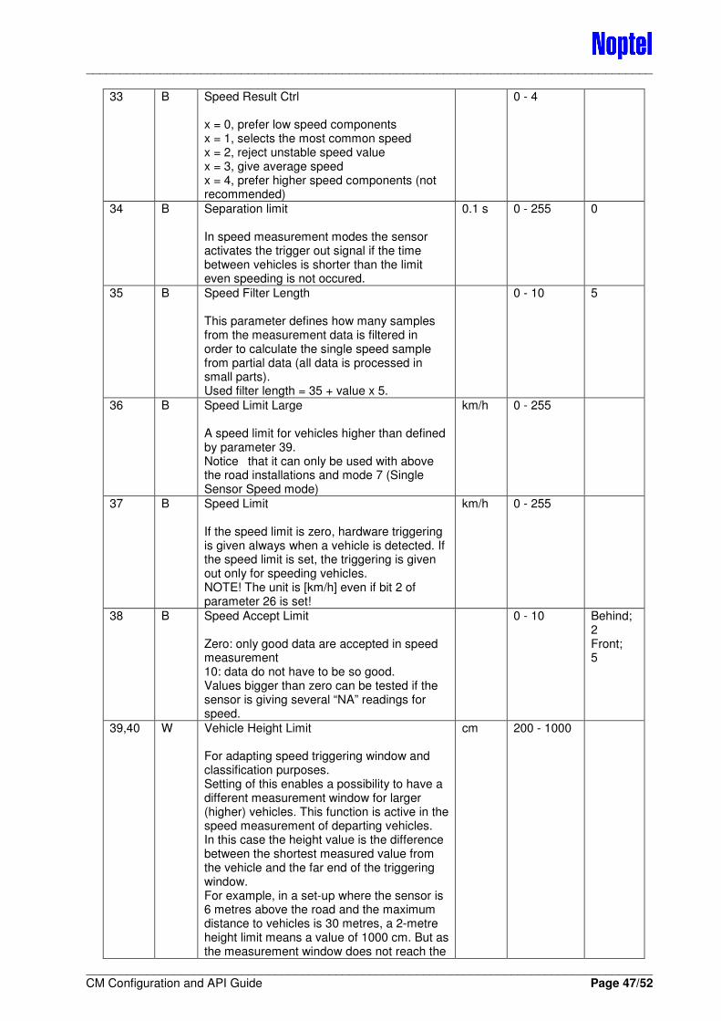
____________________________________________________________________________________
____________________________________________________________________________________ CM Configuration and API Guide Page 47/52
33 B Speed Result Ctrl x = 0, prefer low speed components x = 1, selects the most common speed x = 2, reject unstable speed value x = 3, give average speed x = 4, prefer higher speed components (not recommended)
0 - 4
34 B Separation limit In speed measurement modes the sensor activates the trigger out signal if the time between vehicles is shorter than the limit even speeding is not occured.
0.1 s 0 - 255 0
35 B Speed Filter Length This parameter defines how many samples from the measurement data is filtered in order to calculate the single speed sample from partial data (all data is processed in small parts). Used filter length = 35 + value x 5.
0 - 10 5
36 B Speed Limit Large A speed limit for vehicles higher than defined by parameter 39. Notice that it can only be used with above the road installations and mode 7 (Single Sensor Speed mode)
km/h 0 - 255
37 B Speed Limit If the speed limit is zero, hardware triggering is given always when a vehicle is detected. If the speed limit is set, the triggering is given out only for speeding vehicles. NOTE! The unit is [km/h] even if bit 2 of parameter 26 is set!
km/h 0 - 255
38 B Speed Accept Limit Zero: only good data are accepted in speed measurement 10: data do not have to be so good. Values bigger than zero can be tested if the sensor is giving several “NA” readings for speed.
0 - 10 Behind; 2 Front; 5
39,40 W Vehicle Height Limit For adapting speed triggering window and classification purposes. Setting of this enables a possibility to have a different measurement window for larger (higher) vehicles. This function is active in the speed measurement of departing vehicles. In this case the height value is the difference between the shortest measured value from the vehicle and the far end of the triggering window. For example, in a set-up where the sensor is 6 metres above the road and the maximum distance to vehicles is 30 metres, a 2-metre height limit means a value of 1000 cm. But as the measurement window does not reach the
cm 200 - 1000
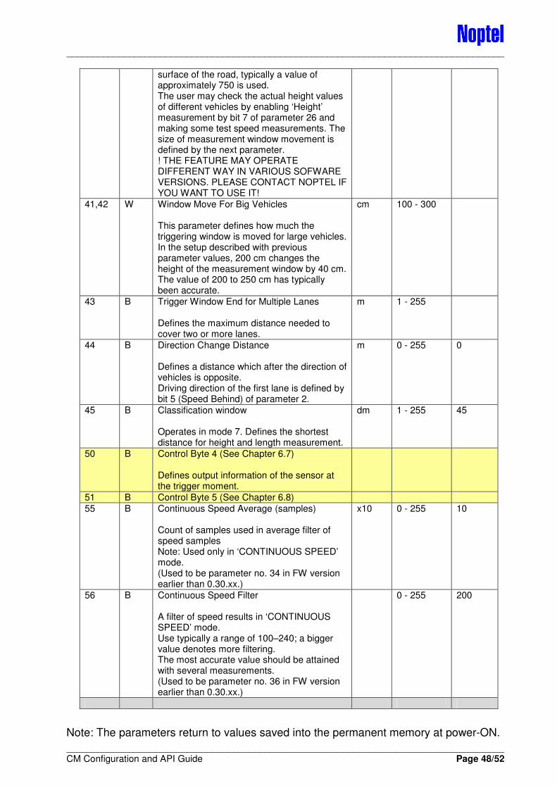
____________________________________________________________________________________
____________________________________________________________________________________ CM Configuration and API Guide Page 48/52
surface of the road, typically a value of approximately 750 is used. The user may check the actual height values of different vehicles by enabling ‘Height’ measurement by bit 7 of parameter 26 and making some test speed measurements. The size of measurement window movement is defined by the next parameter. ! THE FEATURE MAY OPERATE DIFFERENT WAY IN VARIOUS SOFWARE VERSIONS. PLEASE CONTACT NOPTEL IF YOU WANT TO USE IT!
41,42 W Window Move For Big Vehicles This parameter defines how much the triggering window is moved for large vehicles. In the setup described with previous parameter values, 200 cm changes the height of the measurement window by 40 cm. The value of 200 to 250 cm has typically been accurate.
cm 100 - 300
43 B Trigger Window End for Multiple Lanes Defines the maximum distance needed to cover two or more lanes.
m 1 - 255
44 B Direction Change Distance Defines a distance which after the direction of vehicles is opposite. Driving direction of the first lane is defined by bit 5 (Speed Behind) of parameter 2.
m 0 - 255 0
45 B Classification window Operates in mode 7. Defines the shortest distance for height and length measurement.
dm 1 - 255 45
50 B Control Byte 4 (See Chapter 6.7) Defines output information of the sensor at the trigger moment.
51 B Control Byte 5 (See Chapter 6.8)
55 B Continuous Speed Average (samples) Count of samples used in average filter of speed samples Note: Used only in ‘CONTINUOUS SPEED’ mode. (Used to be parameter no. 34 in FW version earlier than 0.30.xx.)
x10 0 - 255 10
56 B Continuous Speed Filter A filter of speed results in ‘CONTINUOUS SPEED’ mode. Use typically a range of 100–240; a bigger value denotes more filtering. The most accurate value should be attained with several measurements. (Used to be parameter no. 36 in FW version earlier than 0.30.xx.)
0 - 255 200
Note: The parameters return to values saved into the permanent memory at power-ON.
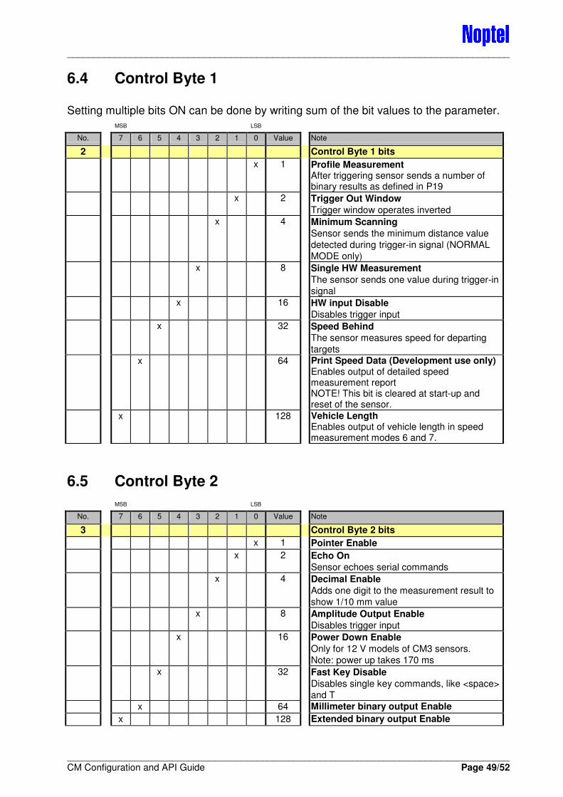
____________________________________________________________________________________
____________________________________________________________________________________ CM Configuration and API Guide Page 49/52
6.4 Control Byte 1
Setting multiple bits ON can be done by writing sum of the bit values to the parameter. MSB LSB
No. 7 6 5 4 3 2 1 0 Value Note
2 Control Byte 1 bits
x 1 Profile Measurement After triggering sensor sends a number of binary results as defined in P19
x 2 Trigger Out Window
Trigger window operates inverted
x 4 Minimum Scanning
Sensor sends the minimum distance value
detected during trigger-in signal (NORMAL
MODE only)
x 8 Single HW Measurement
The sensor sends one value during trigger-in
signal
x 16 HW input Disable
Disables trigger input
x 32 Speed Behind
The sensor measures speed for departing
targets
x 64 Print Speed Data (Development use only) Enables output of detailed speed measurement report NOTE! This bit is cleared at start-up and reset of the sensor.
x 128 Vehicle Length Enables output of vehicle length in speed measurement modes 6 and 7.
6.5 Control Byte 2
MSB LSB
No. 7 6 5 4 3 2 1 0 Value Note
3 Control Byte 2 bits
x 1 Pointer Enable
x 2 Echo On
Sensor echoes serial commands
x 4 Decimal Enable
Adds one digit to the measurement result to
show 1/10 mm value
x 8 Amplitude Output Enable
Disables trigger input
x 16 Power Down Enable
Only for 12 V models of CM3 sensors.
Note: power up takes 170 ms
x 32 Fast Key Disable
Disables single key commands, like <space>
and T
x 64 Millimeter binary output Enable
x 128 Extended binary output Enable
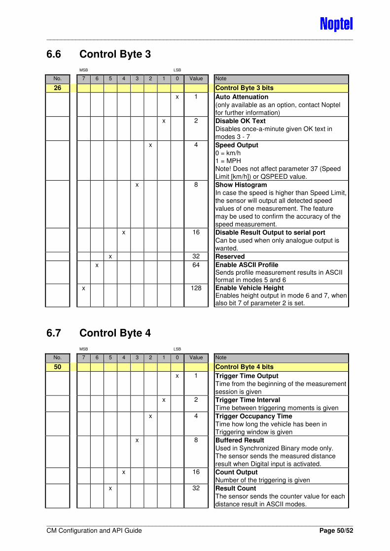
____________________________________________________________________________________
____________________________________________________________________________________ CM Configuration and API Guide Page 50/52
6.6 Control Byte 3
MSB LSB
No. 7 6 5 4 3 2 1 0 Value Note
26 Control Byte 3 bits
x 1 Auto Attenuation
(only available as an option, contact Noptel
for further information)
x 2 Disable OK Text
Disables once-a-minute given OK text in
modes 3 - 7
x 4 Speed Output
0 = km/h
1 = MPH
Note! Does not affect parameter 37 (Speed
Limit [km/h]) or QSPEED value.
x 8 Show Histogram
In case the speed is higher than Speed Limit,
the sensor will output all detected speed
values of one measurement. The feature
may be used to confirm the accuracy of the
speed measurement.
x 16 Disable Result Output to serial port
Can be used when only analogue output is
wanted.
x 32 Reserved
x 64 Enable ASCII Profile Sends profile measurement results in ASCII format in modes 5 and 6
x 128 Enable Vehicle Height Enables height output in mode 6 and 7, when also bit 7 of parameter 2 is set.
6.7 Control Byte 4
MSB LSB
No. 7 6 5 4 3 2 1 0 Value Note
50 Control Byte 4 bits
x 1 Trigger Time Output
Time from the beginning of the measurement
session is given
x 2 Trigger Time Interval
Time between triggering moments is given
x 4 Trigger Occupancy Time
Time how long the vehicle has been in
Triggering window is given
x 8 Buffered Result
Used in Synchronized Binary mode only.
The sensor sends the measured distance
result when Digital input is activated.
x 16 Count Output
Number of the triggering is given
x 32 Result Count
The sensor sends the counter value for each
distance result in ASCII modes.
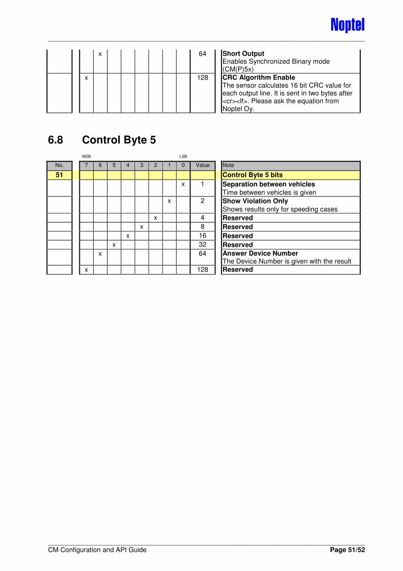
____________________________________________________________________________________
____________________________________________________________________________________ CM Configuration and API Guide Page 51/52
x 64 Short Output Enables Synchronized Binary mode (CM(P)5x)
x 128 CRC Algorithm Enable The sensor calculates 16 bit CRC value for each output line. It is sent in two bytes after <cr><lf>. Please ask the equation from Noptel Oy.
6.8 Control Byte 5
MSB LSB
No. 7 6 5 4 3 2 1 0 Value Note
51 Control Byte 5 bits
x 1 Separation between vehicles
Time between vehicles is given
x 2 Show Violation Only
Shows results only for speeding cases
x 4 Reserved
x 8 Reserved
x 16 Reserved
x 32 Reserved
x 64 Answer Device Number The Device Number is given with the result
x 128 Reserved
Contact information
Noptel Oy Address: Teknologiantie 2
FI-90590 Oulu Finland
Tel.: +358 40 181 4351 Fax: +358 8 556 4101 E-mail: [email protected] Technical support: Web site: www.noptel.fi
CM Distance Sensors
Configuration and API Guide