Closed Cycle Magnetohydrodynamic Nuclear Space Power ... · CloSed CyCle MAGNetoHydRodyNAMIC...
40
NASA/TP—2005–214187 Closed Cycle Magnetohydrodynamic Nuclear Space Power Generation Using Helium/Xenon Working Plasma R.J. Litchford Marshall Space Flight Center, Marshall Space Flight Center, Alabama N. Harada Nagaoka University of Technology, Nagaoka, Japan September 2005 https://ntrs.nasa.gov/search.jsp?R=20060009455 2020-02-02T15:41:59+00:00Z
Transcript of Closed Cycle Magnetohydrodynamic Nuclear Space Power ... · CloSed CyCle MAGNetoHydRodyNAMIC...

NASA/TP—2005–214187
Closed Cycle Magnetohydrodynamic Nuclear Space Power Generation Using Helium/Xenon Working PlasmaR.J. LitchfordMarshall Space Flight Center, Marshall Space Flight Center, Alabama
N. HaradaNagaoka University of Technology, Nagaoka, Japan
September 2005
National Aeronautics andSpace AdministrationIS04George C. Marshall Space Flight CenterMarshall Space Flight Center, Alabama35812
https://ntrs.nasa.gov/search.jsp?R=20060009455 2020-02-02T15:41:59+00:00Z

The NASA STI Program Office…in Profile
Since its founding, NASA has been dedicated tothe advancement of aeronautics and spacescience. The NASA Scientific and Technical Information (STI) Program Office plays a keypart in helping NASA maintain this importantrole.
The NASA STI Program Office is operated by Langley Research Center, the lead center for NASA’s scientific and technical information. The NASA STI Program Office provides access to the NASA STI Database, the largest collection of aeronautical and space science STI in the world. The Program Office is also NASA’s institutional mechanism for disseminating the results of its research and development activities. These results are published by NASA in the NASA STI Report Series, which includes the following report types:
• TECHNICAL PUBLICATION. Reports of completed research or a major significant phase of research that present the results of NASA programs and include extensive data or theoretical analysis. Includes compilations of significant scientific and technical data and information deemed to be of continuing reference value. NASA’s counterpart of peer-reviewed formal professional papers but has less stringent limitations on manuscript length and extent of graphic presentations.
• TECHNICAL MEMORANDUM. Scientific and technical findings that are preliminary or of specialized interest, e.g., quick release reports, working papers, and bibliographies that contain minimal annotation. Does not contain extensive analysis.
• CONTRACTOR REPORT. Scientific and technical findings by NASA-sponsored contractors and grantees.
• CONFERENCE PUBLICATION. Collected papers from scientific and technical conferences, symposia, seminars, or other meetings sponsored or cosponsored by NASA.
• SPECIAL PUBLICATION. Scientific, technical, or historical information from NASA programs, projects, and mission, often concerned with subjects having substantial public interest.
• TECHNICAL TRANSLATION. English-language translations of foreign
scientific and technical material pertinent to NASA’s mission.
Specialized services that complement the STI Program Office’s diverse offerings include creating custom thesauri, building customized databases, organizing and publishing research results…even providing videos.
For more information about the NASA STI Program Office, see the following:
• Access the NASA STI Program Home Page at http://www.sti.nasa.gov
• E-mail your question via the Internet to [email protected]
• Fax your question to the NASA Access Help Desk at 301–621–0134
• Telephone the NASA Access Help Desk at 301–621–0390
• Write to: NASA Access Help Desk NASA Center for AeroSpace Information 7121 Standard Drive Hanover, MD 21076–1320 301–621–0390

�
NASA/TP—2005–214187
Closed Cycle Magnetohydrodynamic Nuclear Space Power Generation Using Helium/Xenon Working PlasmaR.J. LitchfordMarshall Space Flight Center, Marshall Space Flight Center, Alabama
N. HaradaNagaoka University of Technology, Nagaoka, Japan
September 2005
Nat�onal Aeronaut�cs andSpace Adm�n�strat�on
Marshall Space Fl�ght Center • MSFC, Alabama 35812

��
Ava�lable from:
NASA Center for AeroSpace Informat�on Nat�onal Techn�cal Informat�on Serv�ce7121 Standard Dr�ve 5285 Port Royal RoadHanover, MD 21076–1320 Springfield, VA 22161301–621–0390 703–487–4650
Acknowledgments
Th�s work was carr�ed out at NASA’s Marshall Space Fl�ght Center under the ausp�ces of a v�s�t�ng sc�ent�st cooperat�ve agreement between the Japanese M�n�stry of Educat�on, Culture, Sports, Sc�ence and Technology
and NASA Headquarters, Wash�ngton DC.

���
tAble of CoNteNtS
1. INTRODUCTION ......................................................................................................................... 1
2. NUCLEAR FISSION REACTOR/CLOSED CYCLE MAGNETOHYDRODYNAMIC SPACE POWER PLANT ............................................................................................................... 3
3. ANALYSIS .................................................................................................................................... 5
3.1 Number of Compressor Stages ............................................................................................... 5 3.2 Regenerator Efficiency ............................................................................................................ 5 3.3 Rad�ator Cooler Temperature .................................................................................................. 5
4. SPECIFIC MASS ANALYSIS ...................................................................................................... 7
5. RESEARCH AND TECHNOLOGY PLAN .................................................................................. 8
5.1 Phase I—Proof of Pr�nc�ple .................................................................................................... 8 5.2 Phase II—Power Generat�on Demonstrat�on .......................................................................... 9 5.3 Phase III—Prototyp�cal Closed Loop Test .............................................................................. 9
6. CONCLUSIONS ............................................................................................................................ 11
REFERENCES ................................................................................................................................... 12

�v

v
lISt of fIGUReS
1. Schemat�c of NFR/CCMHD space power generat�on system .......................................... 14
2. Influence of compressor stage number on compressor power and plant efficiency ........................................................................................................................... 15
3. T-s d�agram for NFR/CCMHD system assum�ng regenerator efficiencies 1, 0.6, and 0.2 ................................................................................................. 16
4. Influence of regenerator efficiency on regenerated power, MHD thermal power, and plant efficiency ............................................................................................... 17
5. T-s d�agram of the present NFR/CCMHD system for rad�at�on cooler temperatures 300, 500, and 700 K .................................................................................... 18
6. Influence of radiation cooler temperature on radiated heat power and plant efficiency ........................................................................................................... 19
7. Calculated system specific mass as functions of net output power and rad�ator temperature ................................................................................................... 20
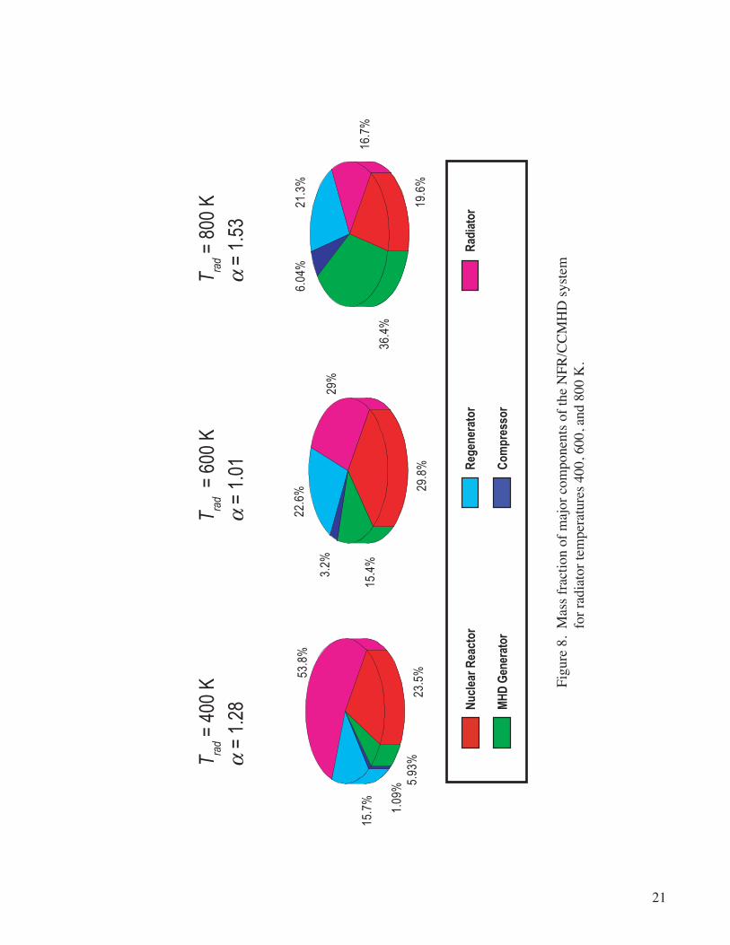
8. Mass fract�on of major components of the NFR/CCMHD system for rad�ator temperatures 400, 600, and 800 K ................................................................. 21
9. Conceptual des�gn of phase I, proof-of-pr�nc�ple exper�ment .......................................... 22
10. Conceptual des�gn of phase II, MHD power generat�on demonstrat�on exper�ment ......................................................................................................................... 23
11. Des�gn loft�ng of phase II d�sk generator channel ............................................................ 24
12. Computed plasma parameter var�at�ons �n phase II d�sk generator channel ..................... 25

v�
lISt of tAbleS
1. Basel�ne cond�t�ons and systems analys�s summary ............................................................ 4
2. Phase I exper�ment operat�ng/test cond�t�ons ....................................................................... 8
3. Basel�ne cond�t�ons and MHD d�sk generator des�gn summary ........................................... 10

v��
ACRoNyMS ANd SyMbolS
AR advanced rad�o�sotopes
CCMHD closed cycle magnetohydrodynam�c
He hel�um
IFC internal confinement fission
MHD magnetohydrodynam�c
MIG m�xed �nert gas
MSFC Marshall Space Fl�ght Center
NFR nuclear fission reactor
RF rad�o frequency
SCM superconduct�ng magnet
T.I.T. Tokyo Inst�tute of Technology
Xe xenon

v���
�x
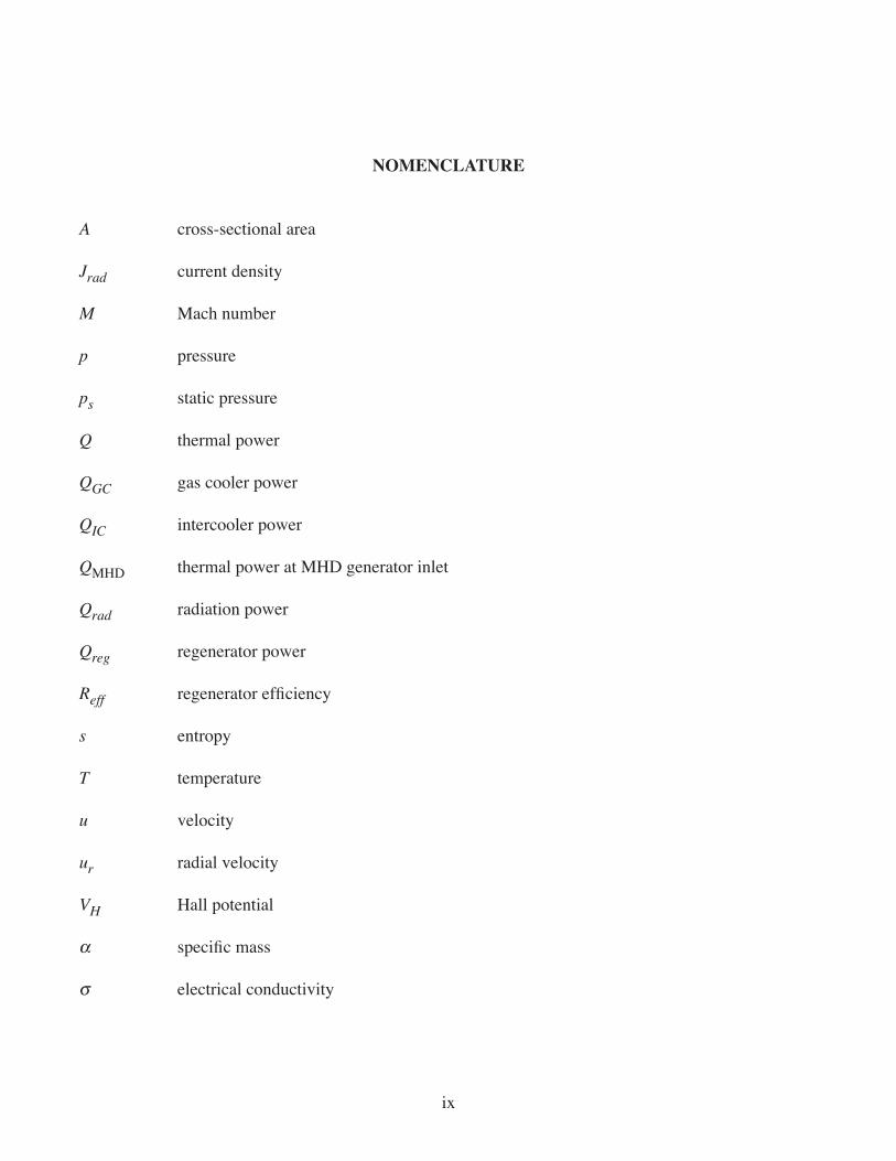
NoMeNClAtURe
A cross-sect�onal area
Jrad current dens�ty
M Mach number
p pressure
ps stat�c pressure
Q thermal power
QGC gas cooler power
QIC �ntercooler power
QMHD thermal power at MHD generator �nlet
Qrad rad�at�on power
Qreg regenerator power
Reff regenerator efficiency
s entropy
T temperature
u veloc�ty
ur rad�al veloc�ty
VH Hall potent�al
a specific mass
σ electr�cal conduct�v�ty

x

1
TECHNICAL PUBLICATION
CloSed CyCle MAGNetoHydRodyNAMIC NUCleAR SPACe PoWeR GeNeRAtIoN USING HelIUM/XeNoN WoRKING PlASMA
1. INtRodUCtIoN
Power generat�on systems �n deep space, relat�vely far from the Sun, cannot rely on solar energy because the ava�lable energy �s �nversely proport�onal to the square of the d�stance from the Sun. M�ss�ons to Jupiter, Jupiter’s icy moons, and beyond will require an alternative heat source and an efficient electric power generat�on system. Even for relat�vely large powered m�ss�on (>0.1 MWe) to Mars, �t has been reported that ut�l�zat�on of solar panels costs much more than ut�l�zat�on of nuclear electr�c power.1
In the first step of the Jupiter Icy Moons Orbiter (JIMO) project, electric propulsion systems w�th output capab�l�t�es of 100–110 kWe are be�ng cons�dered and developed. Also, �n the Prometheus project, nuclear electric power generation systems using advanced radioisotopes (ARs) or nuclear fis-s�on reactors (NFRs) are under �nvest�gat�on. For m�ss�ons requ�r�ng greater electr�c power, NFR and efficient electric power generator systems must be used. Here, a closed cycle magnetohydro- dynam�c (CCMHD) power convers�on system w�thout bottom�ng cycle �s proposed ow�ng to �ts h�gh efficiency and compactness.
Thus far, thermoelectr�c converters, st�rl�ng eng�nes, and turbo-Brayton cycles have been con- s�dered and stud�ed as power convers�on systems �n comb�nat�on w�th AR power for relat�vely smaller m�ss�ons and w�th NFR for larger m�ss�ons.2–6 In part�cular, for large m�ss�ons requ�r�ng over 1 MWe, an electr�c power gas-cooled NFR w�th a CCMHD system has also been cons�dered and stud�ed.7,8 In general, a hel�um (He) and xenon (Xe) m�xture �s used as a coolant �n the gas-cooled reactor due to that m�xture’s excellent heat transfer performance when flowing and good thermal insulation performance when stag-nant.9 The ut�l�zat�on of m�xed �nert gas (MIG), He and Xe �n th�s case, has also been proposed as a work-�ng med�um for the CCMHD generator to avo�d us�ng a condensable alkal�-metal seed.10,11 Therefore, the proposed CCMHD system can be d�rectly dr�ven by a gas-cooled NFR and has the potent�al to ach�eve a lower specific mass. A comparison of plant efficiency has been performed, and the CCMHD single cycle was shown to have the highest plant efficiency—up to 60 percent—when combined with an inertial con-finement fusion (ICF) reactor.12 Such high efficiency is mainly due to the elimination of waste heat from a condenser and the reduct�on of gas cooler waste. However, a stand alone magnetohydrodynam�c (MHD) power convers�on system �s more su�table for spacecraft appl�cat�ons. From the v�ew po�nt of system analys�s, the type of heat source �s not �mportant and the same results are expected �f output temperature and pressure are s�m�lar.
2
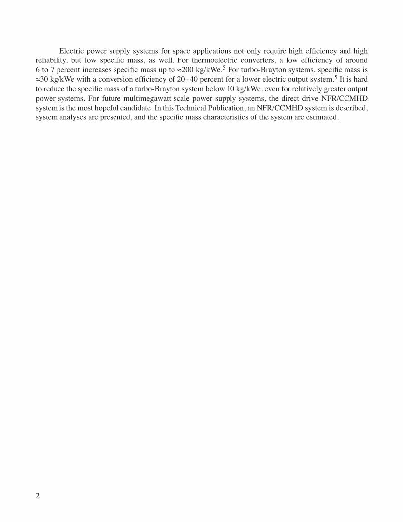
Electric power supply systems for space applications not only require high efficiency and high reliability, but low specific mass, as well. For thermoelectric converters, a low efficiency of around 6 to 7 percent increases specific mass up to ≈200 kg/kWe.5 For turbo-Brayton systems, specific mass is ≈30 kg/kWe with a conversion efficiency of 20–40 percent for a lower electric output system.5 It �s hard to reduce the specific mass of a turbo-Brayton system below 10 kg/kWe, even for relatively greater output power systems. For future mult�megawatt scale power supply systems, the d�rect dr�ve NFR/CCMHD system �s the most hopeful cand�date. In th�s Techn�cal Publ�cat�on, an NFR/CCMHD system �s descr�bed, system analyses are presented, and the specific mass characteristics of the system are estimated.

3
2. NUCleAR fISSIoN ReACtoR/CloSed CyCle MAGNetoHydRo- dyNAMIC SPACe PoWeR PlANt
Prev�ous systems analys�s for CCMHD power convers�on us�ng an IFC reactor showed the h�ghest efficiency among steam turbine, gas turbine, CCMHD, and their possible combined cycles.12 Therefore, an NFR dr�ven CCMHD space power plant has been adopted for deta�led cons�derat�on. F�gure 1 shows a schemat�c of the complete NFR/CCMHD power generat�on system.
A work�ng med�um of He m�xed w�th Xe �s used to connect the CCMHD system d�rectly to the NFR. Alkal�-metal seed �s excluded from the system to avo�d condensed phase handl�ng �ssues, and a MIG system �s adapted a s a means of el�m�nat�ng the system complex�ty assoc�ated w�th seed �nject�on, m�x-�ng, and recovery.10,11 However, the �on�zat�on potent�al of a MIG work�ng med�um �s much h�gher than that of alkal�-metal; therefore, the �on�zat�on level, namely electr�cal conduct�v�ty, �s too low at the reac-tor exit temperature (≈1,800 K) and nonthermal pre-ionization is required. Thus far, microwave, electron beam, hel�con, and RF systems have been cons�dered, and the most su�table one—�n terms of effect�ve-ness, reliability, economy and specific mass attributes—is yet to be determined.
A d�sk-shaped Hall-type MHD generator �s used because of �ts s�mple geometry, m�n�mal electrode connect�ons, and s�mple structure of the superconduct�ng magnet. A heat exchanger, wh�ch �s �nstalled just downstream of the MHD generator, can regenerate generator exhaust heat �n order to m�n�m�ze waste heat rejection and to improve plant efficiency. Other major components include a staged gas compressor with �ntercoolers and a rad�at�on cooler.
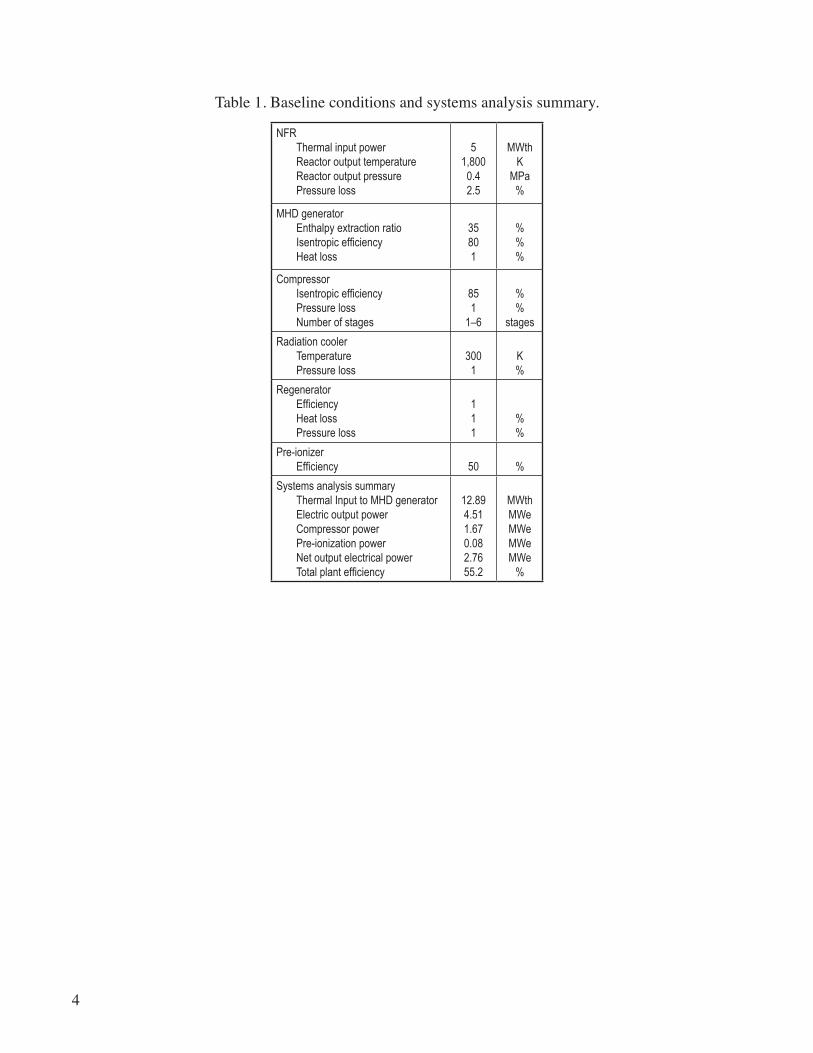
Table 1 shows typ�cal systems analys�s results for an NFR/CCMHD power generat�on system. It can be seen that the regeneration power is ≈8 MW for an NFR thermal output of 5 MWth, giving a thermal �nput to the MHD generator of 12.9 MWth. The net electr�c output of the power plant �s 2.76 MWe because the compressor power (1.67 MWe) and pre-�on�zat�on power (0.08 MWe) are consumed from the total output power of the MHD generator (4.51 MWe). Input power to the system �s 5 MWth, and electric output is 2.76 MWe, which yields a plant efficiency of 55.2 percent. This value is sl�ghtly smaller than the prev�ous results us�ng an ICF reactor and can be ascr�bed to sl�ghtly lower gas temperature at the ex�t of the reactor.
4
Table 1. Basel�ne cond�t�ons and systems analys�s summary.
NFR Thermalinputpower Reactoroutputtemperature Reactoroutputpressure Pressureloss
51,800
0.42.5
MWthK
MPa%
MHDgenerator Enthalpyextractionratio Isentropicefficiency Heatloss
35801
%%%
Compressor Isentropicefficiency Pressureloss Numberofstages
851
1–6
%%
stages
Radiationcooler Temperature Pressureloss
3001
K%
Regenerator Efficiency Heatloss Pressureloss
111
%%
Pre-ionizer Efficiency 50 %
Systemsanalysissummary ThermalInputtoMHDgenerator Electricoutputpower Compressorpower Pre-ionizationpower Netoutputelectricalpower Totalplantefficiency
12.894.511.670.082.7655.2
MWthMWeMWeMWeMWe
%

5
3. ANAlySIS
For the proposed NFR/CCMHD system, only three �ssues need to be exam�ned: (1) Number of compressor stages, (2) regenerator efficiency, and (3) radiation cooler temperature. The power balance analys�s follows the approach prev�ously outl�ned by L�tchford et al.7
3.1 Number of Compressor Stages
Figure 2 shows the compressor power and total plant efficiency compared to the number of compressor stages. Ow�ng to an �ncreased number of �ntercoolers that can reduce the power needed to compress the working gas, plant efficiency increases with the number of compressor stages. Note, how-ever, that this effect is not significant when it exceeds four compressor stages, and three compression stages are opt�mum.
3.2 Regenerator Efficiency
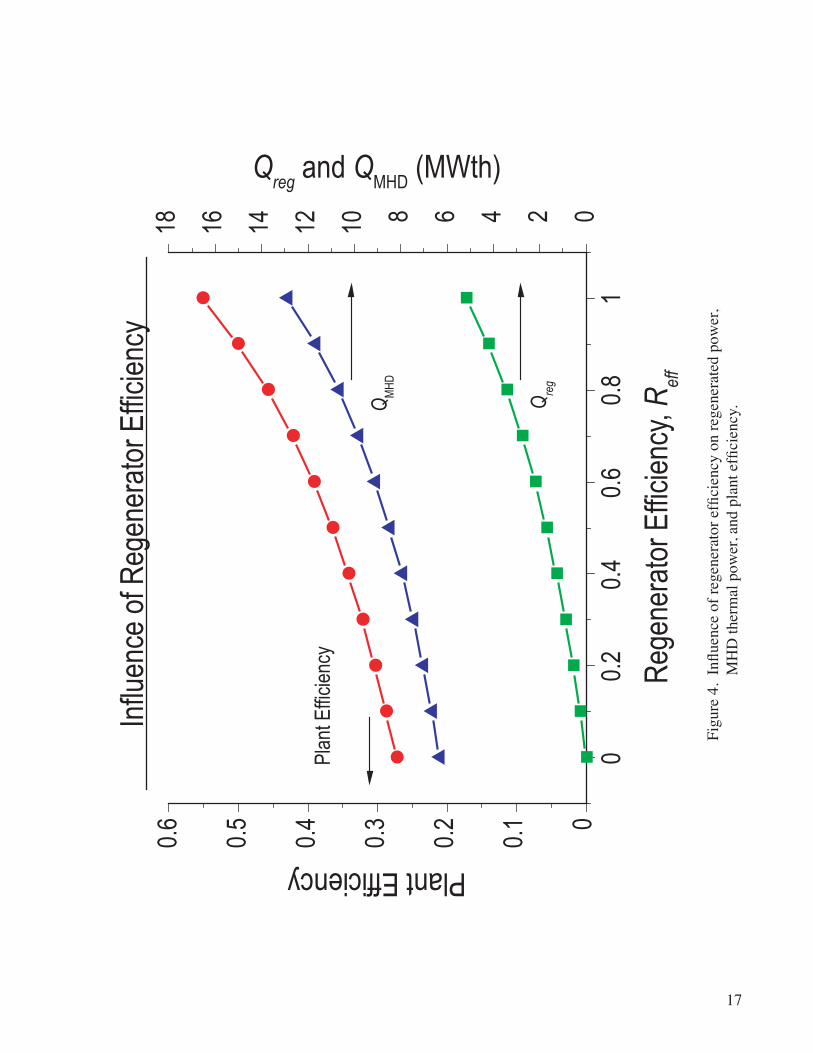
F�gure 3 shows the temperature-entropy, T-s, diagram of the present system for regenerator effi-c�enc�es of 1, 0.6, and 0.2. Here, the NFR ex�t cond�t�ons are set as the entropy reference po�nt where both temperature and pressure are fixed. For a regenerator efficiency of 1, the working gas gains thermal energy during processes 1 through 3 (fig. 3) (i.e., heat from the regenerator from process 1 to 2 and heat from the NFR from 2 to 3). Po�nts 3 and 4 correspond to the NFR and MHD generator ex�ts, respect�vely. F�gure 4 shows regenerated power, Qreg, (at 1 to 2 in fig. 3); thermal input to the MHD generator, QMHD; and total plant efficiency as a function of regenerator efficiency. Here, the temperature difference between high- and low-temperature fluids is assumed as to be 50 K. When regenerator efficiency is decreased (�.e., regenerated heat �s reduced), thermal �nput to the MHD generator �s also decreased because the thermal output from the NFR �s kept at the same level, 5 MWth. Thus, decreased output power from the MHD generator leads to a decrease in total plant efficiency. If the regenerator is removed from the system, plant efficiency decreases ≈28 percent. If this lower level of plant efficiency is acceptable, the regenerator can be removed from the system in order to reduce specific mass. However, to obtain the same level of electr�c output as produced by a system w�th fully regenerated heat, the scale of NFR, MHD genera-tor, and rad�at�on cooler �s expected to be doubled. A more deta�led compar�son should be exam�ned to achieve the lowest specific mass.
3.3 Radiator Cooler temperature
F�gure 5 shows the temperature-entropy, T-s, d�agram of the present system for rad�at�on cooler temperatures of 300 , 500, and 700 K. The NFR thermal output and MHD enthalpy extract�on are the same for all rad�at�on cooler temperatures. However, generated electr�c power, wh�ch corresponds to the area surrounded by the diagram, increases significantly with a decrease in radiation cooler temperature. This means that the plant efficiency is strongly dependent on cooler temperature. Figure 6 shows radiated waste heat, Qrad, wh�ch cons�sts of waste heat from the gas cooler, QGC, and the �ntercoolers, QIC, and total plant

6
efficiency against radiator temperature. In space, this waste heat must be rejected by the radiation cooler. Therefore, the radiation cooler will be larger in general and cause an increase in specific mass. This radia-tor temperature is the lowest temperature of the cycle and also has a strong influence on plant efficiency. It can be seen in figure 6 that plant efficiency decreases significantly with increasing cooler temperature, and net output power approaches zero when the cooler temperature reaches 800 K. Because the rad�ated power depends strongly on rad�at�on cooler temperature, lower temperature requ�res much larger rad�at�on cooler area. Adequate radiation cooler temperature must be clarified.

7
4. SPeCIfIC MASS ANAlySIS
Specific mass, which is mass per unit electrical output power (kg/kWe), must be calculated for each component of the NFR/CCMHD system. Th�s analys�s has been carr�ed out on the bas�s of pr�or work by L�tchford et al.7
The resulting system specific mass predictions are shown in figure 7 as functions of net output power and radiator temperature. A radiator temperature of ≈600 K provides the minimum specific mass for all net output power levels. In order to clarify why the minimum specific mass is achieved at the rad-iation temperature of ≈600 K, mass fractions of major components are shown in figure 8 for radiation cooler temperatures of 400, 600, and 800 K. When rad�ator temperature �ncreases, rad�at�on area becomes smaller to release waste heat, and as a result the specific mass of the radiator is also reduced, as shown in figure 8. At the same time, however, a larger MHD generator and a larger superconducting magnet are required to provide the same net electrical output power because total plant efficiency declines with increasing cooler temperature. As shown in figure 8, the mass fraction of the MHD generator and magnet at a rad�at�on temperature of 800 K �s 36.4 percent, wh�ch �s tw�ce as large as the mass fract�on when at a rad�at�on temperature of 600 K. On the other hand, the mass of the rad�ator �tself �s large and accounts for >50 percent of the total system mass at a rad�ator temperature of 300 K. Th�s results �n an �ncrease of specific mass compared with the 600 K case.
If an appropriate radiator temperature (≈600 K) is chosen, the specific mass decreases with increas-ing net electric output power, as can be seen in figure 7. The expected result is a system specific mass of ≈3 kg/kWe at 1 MWe, 2–3 kg/kWe at 2 MWe, and <2 kg/kWe for >3 MWe. These values are in general agreement w�th the results reported �n reference 8. The present NFR/CCMHD power generat�on system could provide both a higher plant efficiency and a much lower specific mass for multimegawatt electrical power levels �n compar�son w�th other energy convers�on systems.

8
5. ReSeARCH ANd teCHNoloGy PlAN
It has been confirmed that the proposed NFR/CCMHD power generation system has the potential to achieve a specific mass of less than 3 Kg/kWe for multimegawatt space power plants. Therefore, we propose a three-phase research and development plan of CCMHD generator, as follows: (1) Phase I— proof of pr�nc�ple, (2) Phase II—demonstrat�on of power generat�on, and (3) Phase III—prototyp�cal closed loop test.
5.1 Phase I—Proof of Principle
The performance of a CCMHD generator us�ng an He/Xe m�xture as work�ng med�um depends on �on�zat�on and recomb�nat�on processes.11 Furthermore, stable operat�on �n the reg�me of a fully �on�zed seed and avo�dance of �on�zat�on �nstab�l�ty can not be expected because the �on�zat�on potent�al of Xe �s close to that of He. Prev�ous stud�es have shown that He/Xe plasma can be kept stable, and performance comparable to alkal�-metal seeded systems can be expected when the character�st�c t�me of recomb�nat�on �s long compared to the plasma res�dence t�me. In th�s phase, therefore, the ma�n object�ve �s to determ�ne whether or not the �on�zat�on level (�.e., electron number dens�ty and electr�cal conduct�v�ty) can be kept h�gh throughout the d�sk MHD channel. In pract�ce, the �on�zat�on level �s electr�cally elevated well above the thermal equ�l�br�um level us�ng a pre-�on�zer at the d�sk �nlet. If the character�st�c t�me for recomb�-nat�on �s much longer than the res�dence t�me of the work�ng gas �n the channel, the process can be con-s�dered “frozen,” and the �on�zat�on level can be kept h�gh. In th�s case, the plasma becomes stable and h�gh generator performance can be ach�eved w�thout the presence of alkal�-metal seed. To understand th�s process, �t �s necessary to measure electron number dens�ty and electr�cal conduct�v�ty �n the decay reg�on downstream of the pre-�on�zat�on source.
Figure 9 shows a schematic of the proof-of-principle experiment. The mass flow rate of the mixture �n the apparatus �s 0.16 kg/s, wh�ch �s the same as for the power demonstrat�on �n Phase II. The gas m�xture w�ll be �on�zed �n the plenum us�ng a rad�o frequency d�scharge, m�crowave, hel�con, or electron beam pre-�on�zat�on system. In order to ach�eve an �on�zat�on degree of 10–4–10–6, pre-�on�zat�on power �s est�mated to be ≈3 kWe, assuming an ionization efficiency of 50 percent. An acceleration nozzle is located between the pre-�on�zat�on chamber and the test sect�on to s�mulate the MHD channel entrance reg�on. Changes �n electron number density and electrical conductivity along the flow direction will be measured in the test sect�on us�ng m�crowave cut-off, attenuat�on, and phase sh�ft. The t�me durat�on of the exper�ments w�ll be seconds to m�nutes, depend�ng on measurement requ�rements. Operat�ng cond�t�ons are summar�zed �n table 2.
Table 2. Phase I exper�ment operat�ng/test cond�t�ons.
Location M T (K) p (MPa) u (m/s) A (cm2)
Pre-ionizerTestsection
0.31
291225
0.1860.097
301883
17.38.7
PlenumStagnationConditions:T0=300K,P0=0.2MPa.

9
5.2 Phase II—Power Generation demonstration
Phase II efforts w�ll be devoted to power generat�on demonstrat�on exper�ments. A schemat�c of the Phase II experiment is shown in figure 10, where scale and operating parameter ranges are governed by both cost and research and development requirements. A He/Xe working gas mixture is first heated to 1,800 K, the expected ex�t temperature of an NFR, us�ng an electr�c heater and a 1.5 MWe Aerotherm arc heater. The gas ex�t temperature of the vapor core reactor �s cons�dered to be �n that range wh�le the ex�t temperature of d�rect-dr�ve gas-cooled reactor would be around 900 to 1,150 K.8,9 Next, pre-�on�zed working gas is introduced to the disk MHD generator, and a magnetic field is applied by a 3-T supercon-duct�ng magnet. Because a h�gher Hall parameter must be ma�nta�ned �n the d�sk generator channel, the stagnation pressure should be ≈0.2 MPa at this magnetic field strength with a Mach number of around 2 to 2.5 at the disk channel inlet. For the pin-type gas-cooled reactor, the operating pressure is ≈2.4 MPa. Thus, the opt�mum des�gn of an MHD generator and operat�ng cond�t�ons for lower temperature and h�gher gas pressure should also be studied. In the Phase II configuration, the exit of the generator must be connected to the ejector to keep the back pressure su�tably low.
To obtain the specified thermal input, the He/Xe mixture would be preheated to 1,050 K using an electr�c heater then add�t�onally heated to 1,800 K us�ng an arc heater hav�ng a net �nput power to the work�ng gas of 750 kW; therefore, the total thermal �nput to the work�ng gas �s 1.5 MWth. Th�s thermal �nput �s comparable to the He shock tube exper�ments at T.I.T., wh�ch has demonstrated enthalpy extrac-t�on rat�os >30 percent. Stagnat�on gas temperature must be close to the ex�t temperature of an NFR, wh�ch was set at 1,800 K. The requ�red net electr�c power for pre-�on�zat�on of Xe, up to an �on�zat�on degree of 10–4 to 10–6, is ≈4.7 kWe, and pre-ionizer power must be ≈10 kWe if ionization efficiency is assumed to be ≈50 percent. The proposed operating conditions and results of the preliminary MHD generator design are summarized in table 3. The MHD channel-shape design is shown in figure 11. Inlet and exit radii are 0.05 and 0.2 m, respectively. Channel height is <0.02 m and total channel height, including thermal insulator and support structure, is expected to be <0.1 m. This channel fits within Marshall Space Flight Center’s (MSFC’s) existing 3-T superconducting magnet, and operation with a higher magnetic field, if ava�lable, could reduce the warm gap from 12 to 5 �n. F�gure 12 shows plasma parameter d�str�but�ons �n the d�sk MHD channel.
In the Phase II power generat�on exper�ment, �t should be poss�ble to demonstrate >20 percent enthalpy extraction. In the system analysis, an enthalpy extraction of 35 percent and isentropic efficiency of 80 percent are assumed. This level of performance can be confirmed through numerical simulations if the magnetic field strength is increased to 8 T.
5.3 Phase III—Prototypical Closed loop test
Phase III efforts w�ll be devoted to construct�ng a complete closed loop w�th a s�mulated nuclear heat source and conducting continuous power generation tests to confirm generator performance. The main objectives will be to confirm closed-loop system stability, start-up and shut-down operations, output controllab�l�ty, system rel�ab�l�ty, and durab�l�ty. Ult�mately, the CCMHD system should be connected to an NFR as a ground test demonstrat�on.

10
Table 3. Basel�ne cond�t�ons and MHD d�sk generator des�gn summary
Baselineoperatingconditions Workingfluid Thermalinputpower Stagnationtemperature Stagnationpressure Massflowrate Seedfraction Pre-ionizationpower
He/Xe(seed)1.5
1,8000.2
0.1610–5–10–4
4.7
MWthK
MPakg/s
kWe(net)
MHDdiskgeneratordesignsummary Inletradius Exitradius Inletheight Exitheight InletMachnumber ExitMachnumber Inletradialvelocity Exitradialvelocity Outputcurrent Outputvoltage Outputelectricalpower Enthalpyextractionratio
5201.51.12
0.642,3101,340122.42,9050.35623.7
cmcmcmcm
m/sm/sAV
MWe%

11
6. CoNClUSIoNS
A mult�megawatt class NFR powered CCMHD space power plant cycle us�ng a He/Xe work�ng gas has been stud�ed. Th�s �ncluded a deta�led system analys�s and the format�on of a comprehens�ve research and technology plan.
The major conclus�ons of the system analys�s are as follows:
• A CCMHD nuclear space power generat�on system, wh�ch does not rely on the use of condensable alkali-metal seed, was proposed. The total plant efficiency was expected to be 55.2 percent, including pre-�on�zat�on power.
• Three compressor stages were sufficient from a plant efficiency perspective.
• Regenerator efficiency affected the total plant efficiency; if removed, plant efficiency declined from 55 to 28 percent for the full regenerat�ng case.
• Total plant efficiency depended significantly on radiation cooler temperature. The radiator temperature also had a strong influence on power plant specific mass.
• Minimum system specific mass occurred at a radiation cooler temperature of ≈600 K.
• System specific mass was estimated to be ≈3 kg/kWe for a net electrical output power of 1 MWe, 2–3 kg/kWe at 2 MWe, and ≈2 kg/kWe at >3 MWe.
A three-phase research and technology development plan was proposed to �nclude the follow�ng act�v�t�es:
• Phase I—Proof of Principle. Confirm ionization and recombination processes in an He/Xe plasma using a simple cold gas flow experimental facility.
• Phase II—Power Generation Demonstration. Preheat the working mixture with ≈1.5-MWth input to generate a 1,800 K work�ng temperature at the �nlet of a subscale MHD generator. An ex�st�ng 3-T spl�t-co�l superconduct�ng magnet would be used to m�n�m�ze research costs. Based on these assumpt�ons, numer�cal s�mulat�on showed that �t would be poss�ble to ach�eve an enthalpy extract�on �n excess of 20 percent.
• Phase III—Prototyp�cal Closed Loop Test. Conduct system tests w�th a s�mulated heat source rather than an actual NFR. Confirm closed loop system stability, start-up and shut-down operations, output controllab�l�ty, system rel�ab�l�ty, and durab�l�ty.

12
RefeReNCeS
1. Koppel, C.R.; Valentian, D.; Latham, P.; et al.: “Preliminary Comparison Between Nuclear- Electr�c and Solar-Electr�c Propuls�on Systems for Future Mars M�ss�ons,” SpaceTechnologyandApplicationsInternationalForum(STAIF)2004, AIP Proceed�ngs 699, pp. 369–378, 2004.
2. El-Genk, M.S.; and Saber, H.H.: “Cascade Thermoelectr�c Converters-Advanced Rad�o�sotope Power Systems (CTC-ARPSs),” SpaceTechnologyandApplicationsInternationalForum(STAIF)2004, AIP Proceed�ngs 699, pp. 230–241, 2004.
3. El-Genk, M.S.; and Tourn�er, J.-M.: “Conceptual Des�gn of HP-STMCs Space Reactor Power System for 110 kWe,” SpaceTechnologyandApplicationsInternationalForum(STAIF)2004, AIP Proceed�ngs 699, pp. 658–672, 2004.
4. Th�eme, L.G.; and Schre�ber, J.G.: “Advanced Technology Development for St�rl�ng Converters,” SpaceTechnologyandApplicationsInternationalForum(STAIF)2004, AIP Proceed�ngs 699, pp. 432–439, 2004.
5. Zagarola, M.V.; Crowley, C.J.; and Swift, W.L.: “Progress on Low-Power Turbo-Brayton Converters,” SpaceTechnologyandApplicationsInternationalForum(STAIF)2004, AIP Proceed�ngs 699, pp. 453–462, 2004.
6. Godfroy, T.J.; Kapern�ck, R.J.; and Bragg S�tton, S.M.: “Thermally S�mulated 32 kW D�rect Dr�ve Gas Cooled Reactor: Des�gn, Assembly, and Test,” SpaceTechnologyandApplicationsInternationalForum(STAIF)2004, AIP Proceed�ngs 699, pp. 757–763, 2004.
7. L�tchford, R.J.; B�tteker, L.J.; and Jones, J.E.: “Prospects For Nuclear Electr�c Propuls�on Us�ng Closed-Cycle Magnetohydrodynam�c Energy Convers�on,” NASA/TP—2001–211274, 2001.
8. Knight, T.; and Anghaie, S.: “Estimation of Specific Mass for Multimegawatt NEP Systems Based on Vapor Core Reactors with MHD Power,” SpaceTechnologyandApplicationsInternationalForum(STAIF)2004, AIP Proceed�ngs 699, pp. 379–387, 2004.
9. Wr�ght, S.A.; L�p�nsk�, R.J.; Godfroy, T.J.; et al.: “D�rect-Dr�ve Gas-Cooled Reactor Power System: Concept and Prel�m�nary Test�ng,” SpaceTechnologyandApplicationsInternationalForum(STAIF)2003, AIP Proceed�ngs 654, pp. 445–450, 2004.
10. Harada, N.; K�en, L.C.; and Tash�ro, T.: “Closed Cycle MHD Generator us�ng He/Xe Work�ng Plasma,” AIAA Paper, 2002–2144, Proceedingsofthe14thInternationalConferenceonMHDPowerGenerationandHighTemperatureTechnologies, pp. 163–171, 2002.

13
11. Harada, N.; and Tashiro, T.: “Influence of Recombination Coefficient on Discharge Structure and Plasma Stab�l�ty �n Closed Cycle MHD Generator W�th He/Xe Work�ng Gas,” AIAA Paper, 2003–3762, 2003.
12. Kien, L.C.; and Harada, N.: “High Efficiency Closed Cycle MHD Power Generation System for D–T ICF Reactor,” AIAA Paper, 2002–2259, Proceedingsofthe14thInternationalConferenceonMHDPowerGenerationandHighTemperatureTechnologies, pp. 497–505, 2002.

14
F�gu
re 1
. Sc
hem
at�c
of N
FR/C
CM
HD
spac
e po
wer
gen
erat
�on
syst
em.
Pow
erC
ondi
tioni
ng
MH
D D
isk
Gen
erat
or
NFR
Reg
ener
ator
Com
pres
sor B
ank
Rad
iato
r(C
oole
r)
Inte
rcoo
lers
Mot
or
Hig
h-Po
wer
Elec
tric
Thru
ster
4.51
3 M
We
1.67
MW
e
2.76
MW
e
0.08
MW
e
Q =
7.8
94 M
WT
= 1,
102
Kp
= 0.
41 M
Pa
Q =
2.7
06 M
WT
= 37
8 K
p =
0.41
4 M
Pa
Q =
2.1
49 M
WT
= 30
0 K
p =
0.09
3 M
Pa
Q =
8.2
52 M
WT
= 1,
152
Kp
= 0.
095
MPa
Q =
12.
89 M
WT
= 1,
800
Kp
= 0.
4 M
Pa
Q =
3.0
12 M
WT
= 42
0 K
p =
0.09
4 M
Pa
1.114 MWe
0.863 MWe
12
3
4
5
6
Pre-
Ioni
zer

15
Figu
re 2
. In
fluen
ce o
f com
pres
sor s
tage
num
ber o
n co
mpr
esso
r pow
er a
nd p
lant
effi
cien
cy.
12
34
56
0.0
0.2
0.4
0.6
0.81
00.5
11.5
22.5
Num
ber o
f Com
pres
sor S
tage
s
Plant EfficiencyCompressor Power (MWe)
Com
pres
sor
Pow
er
Plan
t Effi
cien
cy

16
F�gu
re 3
. T-
s dia
gram
for N
FR/C
CM
HD
syst
em a
ssum
ing
rege
nera
tor e
ffici
enci
es 1
, 0.6
, and
0.2
.
0
200
400
600
800
1,00
0
1,20
0
1,40
0
1,60
0
1,80
0
2,00
0
Ref
f =
1
Ref
f =
0.6
Ref
f =
0.2
Temperature, T (K)
Entro
py, s
Influ
ence
of R
egen
erat
or E
ffici
ency
Rea
ctor
Exi
t
1
2
3
4
5
6
17
Figu
re 4
. In
fluen
ce o
f reg
ener
ator
effi
cien
cy o
n re
gene
rate
d po
wer
,
MH
D th
erm
al p
ower
, and
pla
nt e
ffici
ency
.
0 0.
2 0.
4 0.
6 0.
8 1
0.6
0.5
0.4
0.3
0.2
0.1 0
18 16 14 12 10 8 6 4 2 0
Plant EfficiencyQ
reg and Q
MHD (MWth)
Reg
ener
ator
Effi
cien
cy, R
eff
Plan
t Effi
cien
cy
Qre
g
QM
HD
Influ
ence
of R
egen
erat
or E
ffici
ency

18
F�gu
re 5
. T-
s d�a
gram
of t
he p
rese
nt N
FR/C
CM
HD
syst
em fo
r rad
�at�o
n co
oler
tem
pera
ture
s 300
, 500
, and
700
K.
2,00
0
1,80
0
1,60
0
1,40
0
1,20
0
1,00
0
800
600
400
200 0
300
(K)
500
(K)70
0 (K
)
Temperature, T (K)
Entro
py, s
Rea
ctor
Exi
t
1
2
3
4
5
6
Influ
ence
of R
adia
tor T
empe
ratu
re

19
Figu
re 6
. In
fluen
ce o
f rad
iatio
n co
oler
tem
pera
ture
on
radi
ated
hea
t pow
er a
nd p
lant
effi
cien
cy.
300
400
500
600
700
800
0
0.1
0.2
0.3
0.4
0.5
0.6
0246810Plant Efficiency
Qrad
, QGC
, and QIC
(MWth)
Rad
iato
r Tem
pera
ture
, Tra
d (K)
Plan
t Effi
cien
cy
QIC Q
GC
Qra
d
Influ
ence
of R
adia
tor T
empe
ratu
re

20
Figu
re 7
. C
alcu
late
d sy
stem
spec
ific
mas
s as f
unct
ions
of n
et o
utpu
t pow
er a
nd ra
diat
or te
mpe
ratu
re.
02
46
810
012345
400
500
600
700
800
Specific Mass (kg/kWe)
Radi
ator
Tem
pera
ture
(K)
Net O
utpu
t Pow
er (M
We)
>
3
3 >
>
2
2 >
>
1
α
α α
21
F�gu
re 8
. M
ass f
ract
�on
of m
ajor
com
pone
nts o
f the
NFR
/CC
MH
D sy
stem
for r
ad�a
tor t
empe
ratu
res 4
00, 6
00, a
nd 8
00 K
.
Nuc
lear
Rea
ctor
MH
D G
ener
ator
Reg
ener
ator
Com
pres
sor
Rad
iato
r
53.8
%
15.7
%
1.09
% 5.93
%23
.5%
T rad =
400
K
= 1.
28T ra
d = 8
00 K
=
1.53
T rad =
600
K
= 1.
01
29%
22.6
%
3.2%
15.4
%
29.8
%
16.7
%
21.3
%6.
04%
36.4
%
19.6
%
αα
α

22
F�gu
re 9
. C
once
ptua
l des
�gn
of p
hase
I, p
roof
-of-
pr�n
c�pl
e ex
per�m
ent.
He
Xe
Plen
umN
ozzl
eTe
st S
ectio
n
Dia
gnos
tics
Mic
row
ave,
Las
erC
ut O
ff, A
ttenu
atio
nPh
ase
Shift
Pre-
Ioni
zatio
nR
F, M
icro
wav
e,H
elic
on, E
-Bea
m

23
F�gu
re 1
0. C
once
ptua
l des
�gn
of p
hase
II, M
HD
pow
er g
ener
at�o
n de
mon
stra
t�on
expe
r�men
t.
Elec
tric
Hea
ter
Dis
k M
HD
G
ener
ator
Pre-
Ioni
zer
MSF
CA
rc H
eate
r M
SFC
3-T
SCM
Load
He
Xe
V
0.75
MW
Pre-
Ioni
zatio
nR
F, M
icro
wav
e,
Hel
icon
, E-B
eam

24
F�gu
re 1
1. D
es�g
n lo
ft�ng
of p
hase
II d
�sk
gene
rato
r cha
nnel
.
–0.2
–0
.1
0
0.1
0.2
–0.0
2
–0.0
1
0.01
0.02
Rad
ius
(m)
Height (m)

25
F�gu
re 1
2. C
ompu
ted
plas
ma
para
met
er v
ar�a
t�ons
�n p
hase
II d
�sk
gene
rato
r cha
nnel
.
0.06
0.08
0.10
0.12
0.14
0.16
0.18
0.2
0
500
1,00
0
1,50
0
2,00
0
2,50
0
3,00
0
3,50
0
02468101214161820
u r
Hall Potential (V), Radial Velocity (m/s)
Rad
ius
(m)
V H
Static Pressure (kPa), Conductivity (S/m)
σ
p s

26
REPORT DOCUMENTATION PAGE Form Approved
OMB No. 0704-0188
Publicreportingburdenforthiscollectionofinformationisestimatedtoaverage1hourperresponse,includingthetimeforreviewinginstructions,searchingexistingdatasources,gatheringandmaintain-ingthedataneeded,andcompletingandreviewingthecollectionofinformation.Sendcommentsregardingthisburdenestimateoranyotheraspectofthiscollectionofinformation,includingsuggestionsforreducingthisburden,toWashingtonHeadquartersServices,DirectorateforInformationOperationandReports,1215JeffersonDavisHighway,Suite1204,Arlington,VA22202-4302,andtotheOfficeofManagementandBudget,PaperworkReductionProject(0704-0188),Washington,DC20503
1. AGENCY USE ONLY (Leave Blank) 2. REPORT DATE 3. REPORT TYPE AND DATES COVERED
4. TITLE AND SUBTITLE 5. FUNDING NUMBERS
6. AUTHORS
7. PERFORMING ORGANIZATION NAME(S) AND ADDRESS(ES) 8. PERFORMING ORGANIZATION REPORT NUMBER
9. SPONSORING/MONITORING AGENCY NAME(S) AND ADDRESS(ES) 10. SPONSORING/MONITORING AGENCY REPO NUMBER
11. SUPPLEMENTARY NOTES
12a. DISTRIBUTION/AVAILABILITY STATEMENT 12b. DISTRIBUTION CODE
13. ABSTRACT (Maximum 200 words)
14. SUBJECT TERMS 15. NUMBER OF PAGES
16. PRICE CODE
17. SECURITY CLASSIFICATION OF REPORT
18. SECURITY CLASSIFICATION OF THIS PAGE
19. SECURITY CLASSIFICATION OF ABSTRACT
20. LIMITATION OF ABSTRACT
NSN7540-01-280-5500 StandardForm298(Rev.2-89)PrescribedbyANSIStd.239-18298-102
Unclassified Unclassified Unclassified Unl�m�ted
Closed Cycle Magnetohydrodynam�c Nuclear Space Power Generat�on Us�ng Hel�um/Xenon Work�ng Plasma
R.J. L�tchford and N. Harada*
George C. Marshall Space Fl�ght CenterMarshall Space Fl�ght Center, AL 35812
Nat�onal Aeronaut�cs and Space Adm�n�strat�onWash�ngton, DC 20546–0001
Prepared by the Propuls�on Research Center, Sc�ence and Technology D�rectorate*Nagaoka Un�vers�ty of Technology, Nagaoka, Japan
Unclassified-UnlimitedSubject Category 20Ava�lab�l�ty: NASA CASI 301–621–0390
A multimegawatt-class nuclear fission powered closed cycle magnetohydrodynamic space power plant us�ng a hel�um/xenon work�ng gas has been stud�ed, to �nclude a comprehens�ve system analysis. Total plant efficiency was expected to be 55.2 percent including pre-ionization power. The effects of compressor stage number, regenerator efficiency, and radiation cooler temperature on plant efficiency were investigated. The specific mass of the power generation plant was also examined. System specific mass was estimated to be 3 kg/kWe for a net electrical output power of 1 MWe, 2–3 kg/kWe at 2 MWe, and ≈2 kg/KWe at >3 MWe. Three phases of research and de-velopment plan were proposed: (1) Phase I—proof of pr�nc�ple, (2) Phase II—demonstrat�on of power generat�on, and (3) Phase III—prototyp�cal closed loop test.
36
M–1149
Techn�cal Publ�cat�onSeptember 2005
NASA/TP—2005–214187
nuclear space power, nuclear electr�c propuls�on, magnetohydrody-nam�cs, energy convers�on

The NASA STI Program Office…in Profile
Since its founding, NASA has been dedicated tothe advancement of aeronautics and spacescience. The NASA Scientific and Technical Information (STI) Program Office plays a keypart in helping NASA maintain this importantrole.
The NASA STI Program Office is operated by Langley Research Center, the lead center for NASA’s scientific and technical information. The NASA STI Program Office provides access to the NASA STI Database, the largest collection of aeronautical and space science STI in the world. The Program Office is also NASA’s institutional mechanism for disseminating the results of its research and development activities. These results are published by NASA in the NASA STI Report Series, which includes the following report types:
• TECHNICAL PUBLICATION. Reports of completed research or a major significant phase of research that present the results of NASA programs and include extensive data or theoretical analysis. Includes compilations of significant scientific and technical data and information deemed to be of continuing reference value. NASA’s counterpart of peer-reviewed formal professional papers but has less stringent limitations on manuscript length and extent of graphic presentations.
• TECHNICAL MEMORANDUM. Scientific and technical findings that are preliminary or of specialized interest, e.g., quick release reports, working papers, and bibliographies that contain minimal annotation. Does not contain extensive analysis.
• CONTRACTOR REPORT. Scientific and technical findings by NASA-sponsored contractors and grantees.
• CONFERENCE PUBLICATION. Collected papers from scientific and technical conferences, symposia, seminars, or other meetings sponsored or cosponsored by NASA.
• SPECIAL PUBLICATION. Scientific, technical, or historical information from NASA programs, projects, and mission, often concerned with subjects having substantial public interest.
• TECHNICAL TRANSLATION. English-language translations of foreign
scientific and technical material pertinent to NASA’s mission.
Specialized services that complement the STI Program Office’s diverse offerings include creating custom thesauri, building customized databases, organizing and publishing research results…even providing videos.
For more information about the NASA STI Program Office, see the following:
• Access the NASA STI Program Home Page at http://www.sti.nasa.gov
• E-mail your question via the Internet to [email protected]
• Fax your question to the NASA Access Help Desk at 301–621–0134
• Telephone the NASA Access Help Desk at 301–621–0390
• Write to: NASA Access Help Desk NASA Center for AeroSpace Information 7121 Standard Drive Hanover, MD 21076–1320 301–621–0390

NASA/TP—2005–214187
Closed Cycle Magnetohydrodynamic Nuclear Space Power Generation Using Helium/Xenon Working PlasmaR.J. LitchfordMarshall Space Flight Center, Marshall Space Flight Center, Alabama
N. HaradaNagaoka University of Technology, Nagaoka, Japan
September 2005
National Aeronautics andSpace AdministrationIS04George C. Marshall Space Flight CenterMarshall Space Flight Center, Alabama35812