Closed Cooling Water (CCW) Coolers
24
The Israel Electric Corp. Ltd. Orot Rabin Power Station Rutenberg Power Station C C l l o o s s e e d d C C o o o o l l i i n n g g W W a a t t e e r r ( ( C C C C W W ) ) C C o o o o l l e e r r s s Project Specification BM-620-P1 Annexure "B"
Transcript of Closed Cooling Water (CCW) Coolers

The Israel Electric Corp. Ltd.
Orot Rabin Power Station
Rutenberg Power Station
CClloosseedd CCoooolliinngg WWaatteerr
((CCCCWW)) CCoooolleerrss
Project Specification BM-620-P1
Annexure "B"
THE ISRAEL ELECTRIC CORP. Ltd. Specification: BM-620-P1
Engineering Projects Group Annexure "B"
Engineering Division Issue: For Proposal
Rev.: December 2011
Page 2 of 24
TTaabbllee ooff ccoonntteennttss ffoorr AAnnnneexxuurree ""BB""
3 Purchaser……………………………………………………………………… 1.
3 Name of Project………………………………………………………………. 2.
3 Location of Project…………………………………………………………... 3.
3 Scope of Work………………………………………………………………… 4.
3 Scope of Engineering and Supply…………………………………………. 4.1
5 Special equipment, tools and instruments………………………………... 4.2
5 Contractor Services…………………………………………………………. 4.3
6 Work by Others……………………….……………………………………… 4.4
7 Documentation……………………….………………………………………. 4.5
7 Terminal connections……………………………..…………………………. 4.6
7 Commissioning and tuning…………………….……………………………. 4.7
7 Guaranteed Performances and Testing…………………………………... 4.8
7 Supplements………………………………………………………………….. 5.
8 Standards and Codes……………………………………………………….. 6.
9 Quality Assurance and Quality Control………………………………….. 7.
11 Shipment and Handling of Goods and Documentation……………….. 8.
12 Safety, Environment and Loading Requirements…………….. 9.
12 Safety……………………………..……………………………………………. 9.1
12 Wind Load……………………….……………………………………………. 9.2
12 Earthquake Loads……..……………………………………………………… 9.3
13 Load Combination……………………………………………………………. 9.4
13 Technical Documentation………………………………………………….. 10.
13 Spare and Renewal Parts…………………………………………………… 11.
13 Power Station Description………………………………………………… 12.
13 Project Description……………..…………………………………………… 13.
14 Mechanical Technical Requirements……………………………………… 14.
23 Painting Requirements…………..………………………………………….. 15.
THE ISRAEL ELECTRIC CORP. Ltd. Specification: BM-620-P1
Engineering Projects Group Annexure "B"
Engineering Division Issue: For Proposal
Rev.: December 2011
Page 3 of 24
SSPPEECCIIFFIICCAATTIIOONN FFOORR
CClloosseedd CCoooolliinngg WWaatteerr ((CCCCWW)) CCoooolleerrss
1. PURCHASER: The Israel Electric Corporation Limited.
2. NAME OF PROJECT: Orot Rabin Power Station, Units 5, 6
Rutenberg Power Station (Optional)
3. LOCATION OF PROJECT: Orot Rabin, Near Hadera
Rutenberg, Near Ashkelon
All P.S. on the Mediterranean Sea Shore
4. SCOPE OF WORK:
4.1 Scope of Engineering and Supply:
4.1.1 Design, manufacture, test, preserve, pack and transport four (4) Gasketed
Plate Heat Exchangers (PHE) for cooling the closed cooling water in Orot
Rabin Power Station– units 5&6 and four (4) Gasketed Plate Heat
Exchangers (PHE) for cooling the closed cooling water in Rutenberg
Power Station – units 1&2 (optional).
4.1.2 The Contractor shall be responsible for the complete design, manufacturing and
testing with specified performances of the complete CCW Coolers.
The system shall be supplied complete including but not limited to the following:
CCW Coolers including equipment, appurtenances and accessories, as
specified herein to form complete systems which will achieve and assure safe
and reliable operation with best overall performance at all loads and modes of
operation.
4.1.3 Scope of supply:
4.1.3.1 The CCW Coolers shall consist but not limited to Four (4) Gasketed Plate and
Frame heat exchangers with titanium heat transfer plates including anchor bolts,
washers and nuts.
THE ISRAEL ELECTRIC CORP. Ltd. Specification: BM-620-P1
Engineering Projects Group Annexure "B"
Engineering Division Issue: For Proposal
Rev.: December 2011
Page 4 of 24
4.1.3.2 The CCW coolers shall be supplied with frame mounted to concrete
foundations.
4.1.4 The Equipment for each Unit shall be supplied complete with appurtenances and
accessories as specified herein, to form a complete system which will achieve
and assure safe and reliable operation with best overall performance at all loads
and modes of operation. All components, appurtenances and accessories shall
be of proven design, verified by Power Plant Operation.
4.1.5 Components that are herein specified in regard to manufacturer brand and
model or type shall be considered the standard of supply. It is not intended that
the Contract be limited solely to such characteristics. The Contractor may make
an appropriate substitution, but all substituted Components offered shall be
noted as EXCEPTIONS to this Specification and are subject to review,
comment, and approval by the Purchaser.
Additionally, while everything else being equal and without derogating from
Contractor's responsibilities under the Contract, the Contractor shall endeavor to
include in the scope of design and supply, components and accessories
manufactured in Israel.
4.1.6 Contractor shall provide, in the required format and form and in a timely manner,
all documentation required by this Specification and/or required by applicable
Standards and Codes and/or as specifically detailed in the Documentation
Submission Schedule (DSS), Annexure "J". A consistent nomenclature shall be
used project-wide in naming all component parts within the Scope of Work. This
shall apply to all drawings, Instruction Books, Bill of Materials, special
instructions, etc. Engineering design shall commence immediately after Contract
award. The cost of correcting inconsistent nomenclature shall be borne by the
Contractor.
4.1.7 Changes in design already approved by the Purchaser are normally unaccepted.
However, should such changes become necessary on an exceptional basis, the

THE ISRAEL ELECTRIC CORP. Ltd. Specification: BM-620-P1
Engineering Projects Group Annexure "B"
Engineering Division Issue: For Proposal
Rev.: December 2011
Page 5 of 24
Contractor shall obtain the Purchaser's approval prior to introducing any such
change.
4.2 Special Equipment, Tools and Instruments
4.2.1 Contractor shall provide all special equipment, tools and instruments required for
safe and secure transport of all components from ex works to final destination,
and for test and maintenance of Equipment provided under this Contract. Said
equipment, tools, and instruments should be listed in Contractor's Proposal
where it is clearly stated which are provided on a loan basis and which are
included in the Contract Price.
4.2.2 The Contractor shall furnish all necessary special tools, instruments and/or test
equipment which are required to fulfill the approved test procedure for equipment
tested by Purchaser.
4.2.3 Maintenance equipment and tools provided under this specification shall be new
and of best quality. They shall be shipped to the job site in a suitable separate
box, clearly marked with the name of the equipment they are intended for.
4.3 Contractor Services
The Contractor shall provide the services listed in the following sub-articles as
part of the basic Scope of Work or as Purchaser’s option, at the per diem or
lump sum rates, all as stated in the Summary of Prices and Delivery Schedule,
Annexure “C1”. Field personnel provided by the Contractor shall be capable and
qualified to perform the required duties to the satisfaction of the Purchaser. They
shall be vested with authority to make decisions that could affect the status of
the Equipment and which are binding on the Contractor.
4.3.1 Erection Services:
4.3.1.1 The Contractor shall provide detailed instructions, drawings and erection
diagrams to permit the Purchaser to organize the erection of all supplied
Equipment.
THE ISRAEL ELECTRIC CORP. Ltd. Specification: BM-620-P1
Engineering Projects Group Annexure "B"
Engineering Division Issue: For Proposal
Rev.: December 2011
Page 6 of 24
4.3.1.2 The Contractor shall furnish detailed instructions to maintain and keep safe
every part of the Equipment during erection until unit start-up.
4.3.2 Commissioning and Start-Up Services:
The contractor shall be responsible for the first successful commissioning of the
CCW coolers. The Contractor shall provide the services of competent start-up
engineer(s) to be responsible for starting and placing into successful service the
equipment provided under this Contract.
4.3.3 Training:
Contractor's personnel shall conduct a thorough training course pertaining to the
equipment furnished under this Specification, for Purchaser's personnel,
covering, without limitation, correct start-up, safe operation at all modes of
operation, safe shutdown and maintenance. The Contractor shall verify that the
trainees are completely familiar with all phases of such procedures and are
capable of operating and maintaining the equipment successfully.
4.3.4 Field Performance Test
Contractor shall delegate at its own cost, qualified test engineer(s), to witness
Equipment field performance tests necessary to establish compliance with this
Specification, and to satisfy that the Equipment fulfills the performance
guarantees, and other Contract requirements.
Field performance tests shall be carried out by the Purchaser, using procedures
provided by the Contractor and approved by the Purchaser according to ASME
PTC and EPA codes, all as further detailed in Annexure "D" – Equipment
Performance Guarantees.
4.4 Work by Others (Facilities and Services to be provided by the Purchaser)
In performing its duties the Contractor shall not be required to provide facilities,
services and equipment as detailed below [further details with respect to
Purchaser's undertaking regarding qualifications, quality, quantities and
scheduling should be stated in Contractor’s proposal]:

THE ISRAEL ELECTRIC CORP. Ltd. Specification: BM-620-P1
Engineering Projects Group Annexure "B"
Engineering Division Issue: For Proposal
Rev.: December 2011
Page 7 of 24
4.5 Documentation
4.5.1 Engineering design shall commence immediately after Contract award,
regardless of the shipping date.
4.5.2 The Contractor shall provide all documentation required by this Specification
and by applicable Standards and Codes, in the required format and form, and
on a schedule as required herein. For further details on required documentation
and its submitted schedule refer to paragraph 10 below
4.6 Terminal Connections
Contractor shall terminate the supply of the equipment provided under this
Specification at the location indicated below. Contractor shall include in the
Proposal a definition for terminal connections not specified in this paragraph:
Point Pipe Size (Inch) Flange Class
Sea water inlet line 14" 150
Sea water outlet line 14" 150
CCW Inlet 12" 150
CCW Outlet 12" 150
4.7 Guaranteed Performances and Testing
The performances of the Equipment shall be verified by a site test in accordance
with the provisions set forth in Annexure “D” to the Contract – Equipment
Performance Guarantees.
5. SUPPLEMENTS
The following supplements are attached hereto and their requirements form an
integral part of this specification - to the extent they are consistent and conform
with the requirements specifically set forth herein. In the event of a variance
between the requirements of the Supplements and the particular requirements

THE ISRAEL ELECTRIC CORP. Ltd. Specification: BM-620-P1
Engineering Projects Group Annexure "B"
Engineering Division Issue: For Proposal
Rev.: December 2011
Page 8 of 24
set forth in the Specification, the requirements specifically set forth in the
Specification shall take precedence.
No. Document ID Document Description
5.1 BM5/11-M62-DS0003-CW Plate heat exchanger data sheet
5.2 Seawater composition Table
5.3 CL-716/1600/99 Specification for Painting on Galvanized
Surfaces by Wet or Electrostatic Powder
Painting.
5.4 Standard 01-1E Standard Specification for Contractor's
Drawing and Data Transmittal
5.5 Q-APP-02-PR Quality Requirements
6. STANDARDS AND CODES
6.1 Standards and Codes referenced in this Specification and in the Supplements to
this specification, form an integral part of this Specification - to the extent their
requirements are consistent and conform with the requirements specifically set
forth herein. All such Standards and Codes are to the issue, including all
amendments, supplements, etc., current as of the date of the Contract, unless
indicated otherwise. In the event of a variance between the requirements of the
Standards and Codes and the particular requirements set forth in the
Specification, the requirements specifically set forth in the Specification shall
take precedence.
6.2 The Equipment to be provided under this Specification, including all
appurtenances and accessories, shall be designed, fabricated, inspected,
tested, stamped and preserved to the extent indicated in said referenced
Standards and Codes. Where this Specification does not include such
reference, The Equipment, or any of its components, shall be designed,
fabricated, inspected, tested and preserved, as applicable, to comply with
currently recognized International and/or Contractor's Standards, whichever are
tighter and more restrictive.

THE ISRAEL ELECTRIC CORP. Ltd. Specification: BM-620-P1
Engineering Projects Group Annexure "B"
Engineering Division Issue: For Proposal
Rev.: December 2011
Page 9 of 24
6.3 The Contractor may propose Standards and Codes as alternates for, or
additions to those specified herein. A copy of each proposed Standard and
code, if any, shall be submitted (in English) for Purchaser's approval. In case
Purchaser's approval is granted, the Contractor shall remain responsible for the
compatibility of the design and the physical interfaces between the supplied
Equipment and the equipment supplied by others.
6.4 The Purchaser shall assist Contractor in identification of Israeli codes and
standards applicable to the Work. In all cases Contractor shall adhere to and
comply with the requirements of Israeli official standards found to be more
restrictive than those specified herein.
6.5 Subject to the provisions stated above, the equipment shall be designed,
manufactured, erected, tested operated and maintained in accordance with the
standards, regulations, directives and publications of the following agencies and
organizations:
ANSI: American National Standards Institute, Inc.
ASME: American Society of Mechanical Engineers.
ASTM: American Society for Testing and Materials.
AWS: American Welding Society.
HEI: Heat Exchanger Institute.
API: American Petroleum Institute.
6.6 The use of other equivalent Standards requires the purchaser agreement.
7. QUALITY ASSURANCE AND QUALITY CONTROL
7.1 Without derogating from the provisions of the General Conditions, Contractor's
quality system shall meet the requirements of Purchaser's Standard Q-APP-02-
PR, "Quality Requirements".

THE ISRAEL ELECTRIC CORP. Ltd. Specification: BM-620-P1
Engineering Projects Group Annexure "B"
Engineering Division Issue: For Proposal
Rev.: December 2011
Page 10 of 24
7.2 The Contractor and the subcontractors shall be certified to ISO-9001-2000 by a
certification body qualified to EN-45004 levels A or C or otherwise as may be
acceptable to the Purchaser.
7.3 The Contractor shall submit upon request a copy of its Quality Assurance
Manual including Quality Procedures.
7.4 The choice of subcontractors shall be subject to Purchaser's approval and the
Contractor shall be responsible for assuring that their quality assurance/quality
control programs, including their organizations, procedures, personnel
qualifications, etc., meet Purchaser’s quality requirements. Contractor [also
Suppliers at the first stage of proposal evaluation] may propose additional
possible sub-suppliers by submitting to the Purchaser a formal request for
approval with sufficient details for evaluation including country of origin for
design and manufacturing, proven experience with respect to equipment of the
same size and functionality, quality assurance, catalogues, functional
parameters and technical data.
7.5 Obligation to meet Israeli Standard SI 4295 (if applicable)
Before shipment and as a condition precedent for delivery, the Contractor shall
supply Purchaser with the certification of the Israeli Standards Institute that its
Equipment conforms to Israeli Standard 4295. [Tender participants should
include in their proposals a written undertaking to comply with SI 4295].
7.6 Materials Validation Testing
a. All materials certificates to be used for the equipment shall be submitted
prior to manufacturing to Purchaser Materials Laboratory for approval.
b. The Purchaser shall have the right, at its discretion, to perform validation
testing of materials, assemblies and fabrications, either at the Contractor's
premises, sub-contractor's premises or in other locations.
c. Validation testing will be used to confirm that materials supplied to the
Contractor's shops are of the appropriate quality, to verify welds, thermal
THE ISRAEL ELECTRIC CORP. Ltd. Specification: BM-620-P1
Engineering Projects Group Annexure "B"
Engineering Division Issue: For Proposal
Rev.: December 2011
Page 11 of 24
treatments and any other measurable property deemed necessary to be
validated by the Purchaser.
d. The validation testing shall be performed either by the Purchaser's own
personnel or by designated persons, acting on behalf of the purchaser.
e. The Contractor shall allow access to the materials and work to be
inspected and shall facilitate the testing.
8. SHIPMENT AND HANDLING OF GOODS AND DOCUMENTATION
The Contractor shall comply with the requirements for Shipment and Handling of
Equipment set forth in Annexure "R" to the Contract and additionally with the
following supplementary requirements:
8.1 All components or accessories shipped detached for field mounting or field
assembly shall be suitably tagged to allow easy identification. Tags shall be
stamped with cross reference data such as Manufacturer's Name, Contract No.,
Power Station, Unit No., reference drawing and Equipment Designation, and
shall be exceptionally durable and securely tied to items by wire or other
methods approved by Purchaser.
8.2 Unless specially designated, all Equipment and other items shall be packaged
for outdoor storage until erection. Where required by the nature of the
Equipment, the Contractor shall furnish and install necessary covers to protect
the Equipment from sand, rain, hail, wind, dust and salt spray. Equipment shall
be adequately sealed and protected during shipment to prevent corrosion and
entrance of foreign matter. All exposed machined surfaces shall be protected
where required with a suitable antirust compound or covers before shipment, for
shipment and storage until erection.
8.3 All temporary supports, lifting lugs and other temporary parts shall be painted in
yellow.

THE ISRAEL ELECTRIC CORP. Ltd. Specification: BM-620-P1
Engineering Projects Group Annexure "B"
Engineering Division Issue: For Proposal
Rev.: December 2011
Page 12 of 24
8.4 The equipment components shall be supplied as large as possible to reduce
field welds and erection time.
9. SAFETY, ENVIRONMENT AND LOADING REQUIREMENTS
9.1 Safety
The Equipment supplied under this Specification shall meet the U.S.
"OCCUPATION, SAFETY, AND HAZARD ADMINISTRATION" (OSHA)
requirements or equivalent.
9.2 Wind Load
The calculation of wind loads in Israel is governed by the provisions of the Israeli
Standard 414 (latest edition at contract signing) “Characteristic Loads in building:
Wind Load”. The calculation shall be accomplished using the basic design wind
velocity.
9.3 Earthquake Loads
9.3.1 General
The seismic design of buildings and structures in Israel is governed by the
provisions of the Israeli Standard 413 “Design Provisions for the Earthquake
Resistance of Structures” (amendment 3 / 2009).
According to this Standard, the seismicity of the site is expressed by the
expected horizontal ground acceleration coefficient Z.
The expected horizontal ground acceleration coefficient Z expressed as:
Z = ah,max/g.
The maximum expected ground acceleration ah,max has the meaning of peak
horizontal ground acceleration, expressed in m/sec2, with a 90% probability not
to be exceeded over a 50 years period. The gravity acceleration g = 9.81 m/sec2.
THE ISRAEL ELECTRIC CORP. Ltd. Specification: BM-620-P1
Engineering Projects Group Annexure "B"
Engineering Division Issue: For Proposal
Rev.: December 2011
Page 13 of 24
The expected horizontal ground acceleration coefficient (Z), per provisions of the
Amendment 3 (2009) to the Israeli Standard 413 is 0.11 for Orot Rabin Power
Station and 0.09 for Rutenberg Power Station.
9.4 Load Combination
Design wind and design earthquake shall not be considered to act at the same
time and their respective effects on the buildings and structures shall not be
combined.
10. TECHNICAL DOCUMENTATION
The Contractor shall submit technical documentation in accordance with the
provisions of Annexure "J" – Documentation Submission Schedule.
11. SPARE AND RENEWAL PARTS
The Contractor shall provide upon purchaser's request as purchaser's option
spare parts at their itemized prices, subject to the applicable terms and
conditions, all as further detailed in Annexure "C1"- Summary of Prices and
Delivery Schedule.
12. POWER STATION DESCRIPTION
The Orot Rabin Power Station comprises two 575MW and four 360MW coal
fired Units. Rutenberg Power Station comprises of two 575MW (Units 1,2) and
two 550MW (Units 3,4) coal fired Units. All power station units are located
alongside the Mediterranean Sea.
13. PROJECT DESCRIPTION
The CCW system is designed to provide cooling water to power station
consumers. The Plate heat exchangers shall be designed to cool the Closed
Cooling Water circuit (CCW) by using Seawater as the primary cooler.
THE ISRAEL ELECTRIC CORP. Ltd. Specification: BM-620-P1
Engineering Projects Group Annexure "B"
Engineering Division Issue: For Proposal
Rev.: December 2011
Page 14 of 24
14. MECHANICAL TECHNICAL REQUIREMENTS
The Plate Heat Exchangers (PHE) shall be designed according to the attached
PHE data sheet (suppl. #5.1) with the following clarifications and additions:
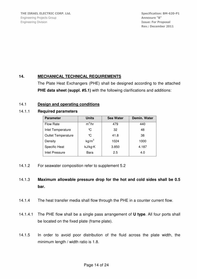
14.1 Design and operating conditions
14.1.1 Required parameters
Parameter Units Sea Water Demin. Water
Flow Rate m3/hr 479 440
Inlet Temperature °C 32 48
Outlet Temperature °C 41.8 38
Density kg/m3 1024 1000
Specific Heat kJ/kg·K 3.850 4.187
Inlet Pressure Bara 2.5 4.0
14.1.2 For seawater composition refer to supplement 5.2
14.1.3 Maximum allowable pressure drop for the hot and cold sides shall be 0.5
bar.
14.1.4 The heat transfer media shall flow through the PHE in a counter current flow.
14.1.4.1 The PHE flow shall be a single pass arrangement of U type. All four ports shall
be located on the fixed plate (frame plate).
14.1.5 In order to avoid poor distribution of the fluid across the plate width, the
minimum length / width ratio is 1.8.
THE ISRAEL ELECTRIC CORP. Ltd. Specification: BM-620-P1
Engineering Projects Group Annexure "B"
Engineering Division Issue: For Proposal
Rev.: December 2011
Page 15 of 24
14.1.6 The PHE shall be designed to allow equally distributed fluid over the full width of
the plates.
14.1.7 The PHE shall be deigned with self cleaning capability.
14.2 Construction Requirements
The construction of the PHE shall meet the following design requirements (refer
to supplement 5.1 – Plate heat exchanger data sheet):
14.2.1 General
14.2.1.1 The PHE shall be designed, constructed, and tested in accordance with ASME
Section VIII, and / or according to the API standard 662 for plate heat
exchangers for general refinery services.
14.2.1.2 The PHE shall comply with the relevant international and local standards and
regulations.
14.2.1.3 The PHE shall be suitable for power plant service and shall be capable of
withstanding vibrations and pulsation due to polluted and marine atmosphere
environment (90% moisture).
14.2.1.4 The contractor is responsible for the complete mechanical design of the plate
heat exchangers in accordance with the requirements of the code and this
specification.
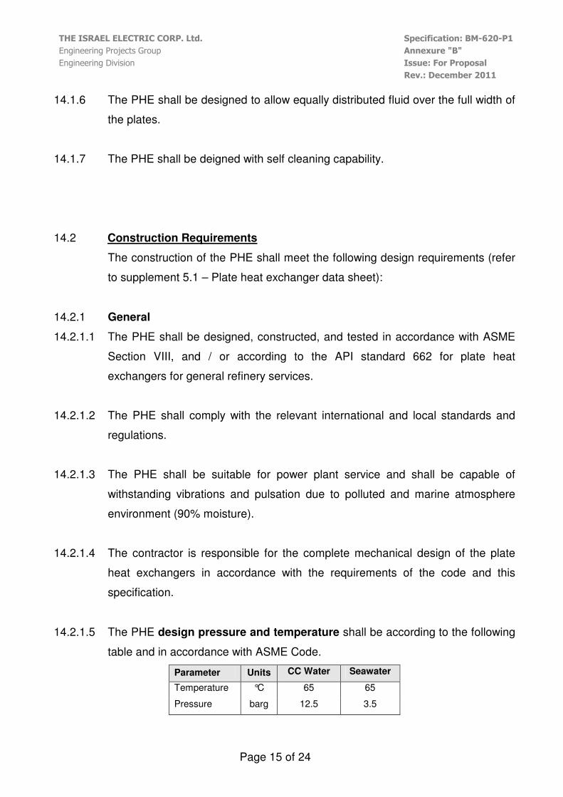
14.2.1.5 The PHE design pressure and temperature shall be according to the following
table and in accordance with ASME Code.
Parameter Units CC Water Seawater
Temperature °C 65 65
Pressure barg 12.5 3.5

THE ISRAEL ELECTRIC CORP. Ltd. Specification: BM-620-P1
Engineering Projects Group Annexure "B"
Engineering Division Issue: For Proposal
Rev.: December 2011
Page 16 of 24
14.2.1.6 For the plate heat exchangers, the Maximum Allowable Working Pressure
(MAWP) shall be design pressure at design temperature and shall be stamped
on the name plate.
14.2.1.7 The fouling factor for the heat exchangers shall be 0.09 (m2·K/ kW).
14.2.1.8 In case of stop or trip of the PHE - the heat exchangers shall be fully drained.
14.2.1.9 The PHE shall be designed to perform the capacities, the pressures, and the
temperatures as shown on this specification.
14.2.1.10 The PHE design shall be based on heat transfer-limited and not be based on
differential pressure.
14.2.1.11 Nominal plate gap shall be 50% larger then the particles size (Debris filter will be
provided by IEC with mesh size of 2mm x 2mm.)
14.2.1.12 All pressure containing parts of carbon steel plate shall be manufactured of fully
killed fine-grained steel (e.g. ASTM A516) unless otherwise approved by the
purchaser.
14.2.1.13 Non-pressure-containing parts (such as lifting lugs – if used, clips and supports)
that are welded directly to pressure parts shall be of RST37-2 or EN235JRG2
carbon steel.
14.2.2 Frame
14.2.2.1 The frame parts Material of Construction shall be according to the following
table:
Part Material
Pressure Plate (Movable Plate)
Frame Plate (Fixed Plate)
Support Column
Carbon Steel
ASTM A516-70
Upper Carrying Bar Stainless Steel
THE ISRAEL ELECTRIC CORP. Ltd. Specification: BM-620-P1
Engineering Projects Group Annexure "B"
Engineering Division Issue: For Proposal
Rev.: December 2011
Page 17 of 24
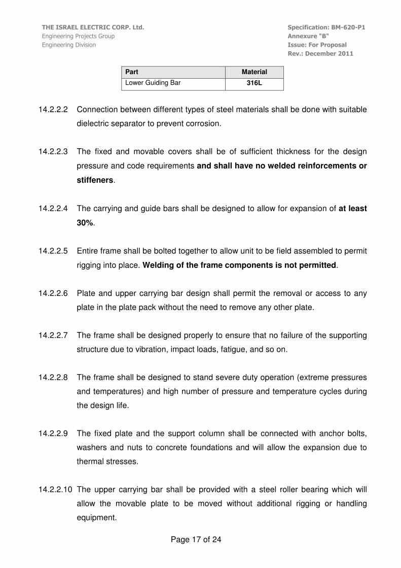
Part Material
Lower Guiding Bar 316L
14.2.2.2 Connection between different types of steel materials shall be done with suitable
dielectric separator to prevent corrosion.
14.2.2.3 The fixed and movable covers shall be of sufficient thickness for the design
pressure and code requirements and shall have no welded reinforcements or
stiffeners.
14.2.2.4 The carrying and guide bars shall be designed to allow for expansion of at least
30%.
14.2.2.5 Entire frame shall be bolted together to allow unit to be field assembled to permit
rigging into place. Welding of the frame components is not permitted.
14.2.2.6 Plate and upper carrying bar design shall permit the removal or access to any
plate in the plate pack without the need to remove any other plate.
14.2.2.7 The frame shall be designed properly to ensure that no failure of the supporting
structure due to vibration, impact loads, fatigue, and so on.
14.2.2.8 The frame shall be designed to stand severe duty operation (extreme pressures
and temperatures) and high number of pressure and temperature cycles during
the design life.
14.2.2.9 The fixed plate and the support column shall be connected with anchor bolts,
washers and nuts to concrete foundations and will allow the expansion due to
thermal stresses.
14.2.2.10 The upper carrying bar shall be provided with a steel roller bearing which will
allow the movable plate to be moved without additional rigging or handling
equipment.
THE ISRAEL ELECTRIC CORP. Ltd. Specification: BM-620-P1
Engineering Projects Group Annexure "B"
Engineering Division Issue: For Proposal
Rev.: December 2011
Page 18 of 24
14.2.2.11 The bearing / roller surface shall permit easy sliding of the plates and movable
cover along the entire length of the upper carrying bar.
14.2.2.12 The carrying bar shall be designed to support at least 1.5 times the total mass of
the movable cover and plate pack with the maximum number of plates filled with
water (or the process fluid if its density is greater than that of water).
14.2.2.13 The PHE shall have a support column located at the movable cover end. A
minimum of two mounting feet shall be provided at the fixed cover. The
contractor shall design the supports for the external loads specified in the
equipment data sheet or requisition documents
14.2.2.14 Fixed and movable plates shall include Lifting holes to allow lifting of the entire
unit's flooded weight.
14.2.2.15 Using of welded lifting lugs is prohibited unless written approval has been issued
by purchaser.
14.2.2.16 Lifting holes diameter shall be sufficient to allow shackles to clear insulation.
14.2.2.17 The plate pack shall be covered with aluminum shroud or other recommended
material under the purchaser approval in accordance with OSHA and to protect
against spray leaks.
14.2.2.18 Corrosion allowance shall apply to connections only and shall be not less then
1.6mm.
14.2.2.19 Connections shall be of the flanged design as per ANSI B16.5 standard. Incase
of choosing other flange standards, the contractor shall provide end welded
neck counter flanges as per ANSI B16.25.

THE ISRAEL ELECTRIC CORP. Ltd. Specification: BM-620-P1
Engineering Projects Group Annexure "B"
Engineering Division Issue: For Proposal
Rev.: December 2011
Page 19 of 24
14.2.2.20 The PHE shall be self-draining and self-venting through the connections for all
pass arrangements.
14.2.2.21 The projection of flanged connections shall be of sufficient length to allow
installation and removal of the flange bolts from either side of the flange.
14.2.2.22 All bolt holes for flanged connections shall straddle centerlines.
14.2.2.23 Connections shall be designed to withstand suitable loads and moments
induced by the piping according to API 610 including Appendix F.
14.2.3 Compression Bolts
14.2.3.1 Compression bolt material shall be carbon steel.
14.2.3.2 The bolting system shall be designed so the compression bolts can be removed
from the side in addition to front / back removal.
14.2.3.3 Compression bolts shall not require special tools and shall be equipped with lock
washers at the movable cover (pressure plate) to facilitate opening and closing
of the unit from the fixed cover (frame plate).
14.2.3.4 Compression bolts shall be equipped with captive nuts at the fixed cover and
threaded nuts at the movable cover. Welding of the nut to the closure bolt is
prohibited.
14.2.3.5 Each tie bolt shall be supplied greased and with a plastic sleeve to protect it
from the environment or will be hot dip and galvanized.
14.2.3.6 Tie bolts shall not be less than 16 mm (5/8 inch) nominal diameter, in
accordance with the pressure design code.
14.2.4 Plates
14.2.4.1 The plates Material shall be made out of Titanium ASTM-B-265-03-Grade 2.
THE ISRAEL ELECTRIC CORP. Ltd. Specification: BM-620-P1
Engineering Projects Group Annexure "B"
Engineering Division Issue: For Proposal
Rev.: December 2011
Page 20 of 24
14.2.4.2 The minimum plate thickness before being pressed shall be 0.6mm.
14.2.4.3 The minimum spacing between the heat transfer plates shall be 2.5mm.
14.2.4.4 Additional 5% of plate's quantity shall be provided above the designed No. of
plates.
14.2.4.5 Each heat transfer plate shall be designed to allow maximum heat transfer with
a minimum pressure loses.
14.2.4.6 Each heat transfer plate shall have built-in self aligning to accurately locate the
plates in the frame assembly and prevent lateral plate movement and maintain
maximum gasket contact under pressure.
14.2.4.7 All heat transfer plates shall have permanently identification stamped for proper
assembly.
14.2.4.8 End heat transfer plates shall be furnished at the fixed and movable covers.
14.2.5 Gaskets
14.2.5.1 Gaskets shall be positioned in a groove around the heat transfer surface and
around the port holes of the plate. Gaskets shall be secured to the plate by glue
or by mechanical means.
14.2.5.2 All Heat Transfer Plates of 0.2m² heat transfer area and bigger will be equipped
with glued gaskets.
14.2.5.3 Each sealing gasket shall be one integral piece.
14.2.5.4 Through-flow port areas of the plates shall be double-gasketed and vented to
the atmosphere in such a manner that cross-contamination of fluids cannot
occur without readily detectable external evidence.
THE ISRAEL ELECTRIC CORP. Ltd. Specification: BM-620-P1
Engineering Projects Group Annexure "B"
Engineering Division Issue: For Proposal
Rev.: December 2011
Page 21 of 24
14.2.5.5 Gaskets shall have relieving grooves to prevent intermixing of fluids and cause
leak to flow to outside of unit.
14.2.5.6 The gaskets shall be made out of NBR (P), EPDM(P) – Peroxide cured or other
recommended material under the purchaser approval.
14.2.5.7 The gasket shall be tested according to the following ISO Test Standards
(Compression set / 815): ISO/188, 37, 48, 1817.
14.2.5.8 The gaskets shall fit around both the heat transfer area and the port holes to
prevent leakage to the surrounding atmosphere and from the channels.
14.2.5.9 The gaskets cross section shall be square or other recommended section under
the purchaser approval.
14.2.5.10 The gaskets shall have long life expectancy and high durability including opening
and closing of the heat transfer plates.
14.2.5.11 If glue is provided, it shall be per the manufacturer recommendation and it shall
be suitable for the conditions stated in this specification.

THE ISRAEL ELECTRIC CORP. Ltd. Specification: BM-620-P1
Engineering Projects Group Annexure "B"
Engineering Division Issue: For Proposal
Rev.: December 2011
Page 22 of 24
Double Gasketed proposed configuration
14.3 Hydrostatic Testing
14.3.1.1 Hydrostatic test shall be in accordance with ASME, Section VIII, Div.1,
paragraph UG-99.
14.3.1.2 For each hydrostatic test, two indicating gauges (or one indicating gauge and
one recording gauge) shall be attached to the PHE.
14.3.1.3 The equipment shall be inspected by Israel standard institute. An inspection
certificate shall be furnished to the purchaser.
14.4 Nameplates and Stamping
14.4.1 A nameplate shall be permanently attached to the PHE and shall include the
following:
� Manufacturer’s name and plate heat exchanger serial number.
� Capacity (kW).
� User’s Tag number.
� Manufacturing Date.
THE ISRAEL ELECTRIC CORP. Ltd. Specification: BM-620-P1
Engineering Projects Group Annexure "B"
Engineering Division Issue: For Proposal
Rev.: December 2011
Page 23 of 24
� Pressure design code and if required, code stamping.
� Design temperature and minimum design metal temperature if applicable.
� Maximum allowable working pressure and Temperature.
� Hydrostatic test pressure.
14.4.2 Any limitations on lifting shall be clearly marked on the PHE.
14.4.3 Nameplates shall be provided in each of the connection ports, indicating the fluid
type, size, class, material, design flow, temperature and pressure and all other
information as required by TEMA and IEC Tag. No.
14.4.4 Nameplates shall be of austenitic stainless steel.
14.5 Shipment preparation
14.5.1 The PHE shall be cleaned and all openings sealed before shipment. Any specific
requirements for drying will be specified by the purchaser.
14.5.2 Tie bolt threads shall be coated with an anti-seizing lubricant.
14.5.3 Exposed machined carbon steel surfaces, including threads extending beyond
the nuts, shall be protected with an easily removable rust-preventive coating.
14.5.4 Exposed flanged connections shall be protected
14.6 Maintenance
14.6.1.1 The PHE shall be designed to be easily opened for inspection, mechanical
cleaning, gasket replacement, extension or reduction the number of plates, or
other modifications of the duties.
14.6.1.2 The contractor shall specify the required clearance around the PHE for
maintenance.
THE ISRAEL ELECTRIC CORP. Ltd. Specification: BM-620-P1
Engineering Projects Group Annexure "B"
Engineering Division Issue: For Proposal
Rev.: December 2011
Page 24 of 24
15. PAINTING REQUIREMENTS
Without derogating from the above, all Carbon Steel equipment shall be supplied
hot dipped or electrolytically galvanized and painted according to Supplement
#5.3 "Specification for Painting On Galvanized Surfaces by Wet or
Electrostatic Powder Painting".
–– FF II NN AA LL ––